Embed Size (px)
Citation preview
Publication # 68-00155 (Rev: B 26-JULY-95) Page 1
®
Model 801GC-ISA & 801GF-ISAISA Video Generator
Programmer’s Manual
How you can control your ISA Generator Are you running under Microsoft Windows®? We provide a full graphics user interface that runs under Microsoft Windows®. You can use a mouse to easily point and click your way through the set-up and operation of the generator.
We also supply a Dynamic Link Library (DLL) file for use by other software packages that run under Windows, such as Visual Basic.
Are you running under Microsoft MS-DOS®? We give you several methods to operate and program the generator from MS-DOS. First, our terminal emulation program lets you talk to the generator on an interactive basis. The generator responds to every instruction as you type.
Another MS-DOS compatible program allows you to quickly send a file containing multiple instructions.
You can also create your own control program using a standard MS-DOS level “C” language and include our supplied C source code.
Which method is best for you? Do you want to operate the generator by itself? If you are you using Windows… You can use our Windows user interface. This is the preferred operating method because you don’t have to do any programming.
If you are you using MS-DOS… We give you two ways to program and operate the generator. You just need to learn a little about the generator’s command language?
You may first want to try out the “Terminal” utility software. This interactive mode of operation lets you get up to speed with the generator’s command language. A later section of this manual explains how to load and run the software. A listing and description of all the commands can be found at the end of this manual.
Next, you can move on to using our “Send” utility software. This utility lets you send an entire file full of commands with one simple command. You first use a text editor to put the command lines into the file. A later section of this manual explains how to load and run the software.
You can also create own your control program using a standard MS-DOS level “C” language? You can include our supplied C source code into your program.
Do you want to operate the generator as part of an ATE system? If you’re using Windows… You can use the Dynamic Link Library (DLL) file on the disk. The DLL file lets you choose any ATE programming language that supports DLLs. A later section of this manual explains how to implement the DLL in your software. If you’re using Visual Basic, appendix C describes a sample file that you can use as a starting point in writing or modifying your own program.
If you’re using MS-DOS… You can write your control program using a standard C language. Just include our C source code in your program. Our supplied code allows you to establish a communications port to the ISA generator and then send commands and inquires to the ISA generator. A later section of this manual explains the high level functions you need to know in the source code.
If none of the above methods meet your needs… Please contact your local sales representative or an applications engineer at Quantum Data. We can work with you to help fit the generator into your particular testing application.
Page 2 Model 801GC-ISA & 801GF-ISA Programming Manual
Using the Windows Compatible User Interface The Windows version of our user interface is the preferred method of operating and programming the ISA generator. It allows you to quickly set-up signal formats, custom test images and sequences without having to learn programming commands. When editing, you first use a mouse to point and click on what you want to change. You then use the mouse to select a new setting from a list or use the keyboard to enter a new numeric entry.
Even if your end application does not use Windows, you may wish to use our Windows interface software to set-up all of your custom formats, images and sequences. All of your work will be stored on the ISA generator in battery backed memory. You can swap boards between computers without loosing any data. The software also gives you the option of saving your data to the computer’s disk drive. This allows to archive the data and quickly download the data into additional boards.
For more information… A separate Quick Start Guide booklet has all the information you need to get the ISA generator up and running under Windows. The guide is included with your generator.
Using the MS-DOS Compatible Terminal Program If your computer has Windows software installed, you should first use our Windows user interface software to become familiar with the use of the generator. This will make it easier for you to understand the types of things you can and can not do with the terminal software.
Before using the program, you should copy it to your computer’s hard disk or onto another floppy. The original should be kept as a back-up copy and not be used for day to day operation. The name of the program is TERM.EXE and it does not need any other support files to run.
When starting the program, you need to tell it the ISA Bus address assigned to the ISA generator. The address is set by jumpers on the generator. The Quick Start Guide has information on setting the jumpers to a particular address. The valid range of address settings is zero (Ø) through seven (7). If your ISA generator has its jumpers set to address 2, the following command, at the MS-DOS prompt, would start terminal communications:
TERM ISA2 <return>
The software starts by looking for an ISA generator at the given ISA address. If it finds one, the name of the program and a copyright notice are shown on the computer’s screen. This followed by an R>prompt from the generator. If a generator is not found, the software displays a “hardware not found” error message and exits to DOS. If you get this error message, you should make sure that the card is fully seated in the expansion connector and that the address jumpers are set properly.
You are now ready to send commands and queries. If you are using the generator and software for the first time, you can try a simple command for starters. Try typing in the following command from the R>prompt:
*IDN? <return>
You have just asked the generator to identify itself. It should respond with “Quantum Data,801GC-ISA,0,firmware version #”, where the actual current firmware version number is shown.
If you are just getting familiar with the terminal program, you may wish to experiment with the generator and software. You can try loading different signal formats by name using the FMTL command. The outputs will not match the loaded format until you use the FMTU or ALLU command. You can try loading different test images by name using the IMGL command. The displayed pattern will not change until you use the IMGU or ALLU command.
To quit the terminal program, hold down the “Alt” key and press the “x” key. This will return you to the DOS prompt.
For more information… All of the commands that you can use are listed and described in appendix B. Appendix A lists a sample command file. These files show a typical series of commands you would need to enter to perform a particular task.
Publication # 68-00155 (Rev: B 26-JULY-95) Page 3
Using the MS-DOS Compatible “Send” Program The “Send” utility program lets you send a command file to your ISA generator. A command file can contain any number of commands.
Before using the program, you should copy it to your computer’s hard disk or onto another floppy. The original should be kept as a back-up copy and not be used for day to day operation. The name of the program is SEND.EXE and it does not need any other support files to run.
When executing the program, you need to tell it the ISA Bus address assigned to the generator and the name of the file you wish to send. The address is set by jumpers on the generator. The Quick Start Guide has information on setting the jumpers to a particular address. The valid range of address settings is zero (Ø) through seven (7). The factory default setting is zero (Ø) If your ISA generator had its jumpers set to address 3, the following command, at the MS-DOS prompt, would send a file you had previously created, called MYFORMAT.CMD:
SEND ISA3 MYFORMAT.CMD <return>
The software starts by looking for both an ISA generator at the given ISA address and for the file. If it finds both, it starts to download the file to the generator. If a generator or the file is not found, the software displays an error message and exits to DOS.
During the download, a progress report is shown on the computer’s screen. The filename and ISA generator address are shown. The software also shows the current command line in the file being sent. If the generator finds an error in a command line, it will be reported on the computer’s screen. The program quits and returns to the DOS prompt when it is done.
All of the commands you can use are listed in appendix B. They are listed two ways. The first method groups them by function. For example, all of the commands to change any format parameter are listed under one heading. There is also a straight alphabetical listing of all of the commands supported by the firmware. This listing also contains descriptions and expected parameters
For more information… All of the commands you can use are listed and described in appendix B. Appendix A lists a typical file you would need to create to perform a particular task.
Using Our Source Code in Your Own C Language Programs The applications disks supplied with the ISA generator includes three commented C language source code files. Two of the files are the complete source code for the Terminal and Send utility programs. The third file shows how you can have different keys on the computer trigger user defined functions on the ISA generator. You can incorporate any portions of our source code that you want into your own MS-DOS level C programs. The three files are named TERM.C, SEND.C and KEYS.C.
Page 4 Model 801GC-ISA & 801GF-ISA Programming Manual
Using Our Dynamic Link Library (DLL) in Your Own Programs Accessing The Dynamic Link Libraries - DLLs A Dynamic Link Library (DLL) is a collection of functions your program can link with dynamically. Quantum Data has created several functions in a DLL called HIA.DLL to assist you with your custom programs.
• Open Port - This external function is called to open an ISA port to allow communication between the PC and the ISA generator.
• Port Command - This routine is designed to download a command or a query to the ISA generator. When a query is sent, this routine will also retrieve a response from the generator.
• Board Init - This function will initialize the ISA generator. Note: This command will erase any custom formats, images or sequences that are currently downloaded in the generator!
To link to a DLL function in Visual Basic is quite different from the way it is done using C. The key to calling a function in a DLL from a Visual Basic application is the Declare statement. Like a C prototype, the Visual Basic Declare statement defines the name of the function, its parameters, the data types of the parameters, and the values returned by the function. But the Declare statement goes one step further and also defines the name of the DLL in which the function resides.
Here are three C functions declarations from HIA.DLL and their corresponding Declare statements:
First the C function declarations: int FAR PASCAL _export port_open (char *portspec, COMM_DATA_TYPE *comm_data); int FAR PASCAL _export port_command (COMM_DATA_TYPE *comm_data, char *cmd, char *response); int FAR PASCAL _export port_init (COMM_DATA_TYPE *comm_data, char *cmd, char *response);
Now the Visual Basic Declare statements: Declare Function port_open Lib ñhia.dllî (ByVal PortSpec as String, Comm_Data as COMM_DATA_TYPE) as Integer
Declare Function port_command Lib ñhia.dllî (Comm_Data as COMM_DATA_TYPE, ByVal cmd as String, ByVal response as String) as Integer
Declare Function board_init Lib ñhia.dllî (Comm_Data as COMM_DATA_TYPE, ByVal cmd as String, ByVal response as String) as Integer
Helpful Hints • These Declare statements should be placed in a global module to allow the functions to be used anywhere in the
application.
• Visual Basic does not have the ability to split a statement across multiple source lines. The above Declare statements were split into multiple lines for readability.
• The best location for the DLL file is in the Windows directory, the Windows system directory, the Visual Basic installation directory or some directory in your path.
Passing Parameters Passing strings in Visual Basic to a C DLL can sometimes be tricky. Visual Basic does not store strings internally as a standard null-terminated string. Instead, VB internally manipulates strings using a 4-byte string descriptor. It is important for the ByVal keyword to be placed on a string parameter in the Declare statement. This allows Visual Basic to pass a pointer to a null-terminated string instead of a pointer to the string descriptor. Although Visual Basic allows variable length strings, passing a variable length string in Visual Basic to a DLL passes a pointer to an area only as long as the current string length. The DLL has no control over the allocation of the string, so there is no way to extend the string when it is passed using ByVal. This means the size of the response string must be declared before the external function is called. (i.e. Global response as string * 100)
Passing the name of a structure from VB to an external function will pass a pointer to the structure, just as it is done in C. To access the Quantum Data DLLs, a COMM_DATA_TYPE structure must be declared. This can be placed in a module along with the Declare statements.
Type COMM_DATA_TYPE
Publication # 68-00155 (Rev: B 26-JULY-95) Page 5
PortType as Integer ‘0-None, 1-ISA, 2-Com Port
PortNum as Integer ‘0-7 ISA, 1-4 Com
Baud as Integer ‘Baud Rate for Com port 300, 600, 1200, 2400, 4800, 9600, 12800, 38400
Parity as Integer ‘Parity 0 = None(N), 1=Even(E), 2=Odd(O)
Data_Bits as Integer ‘The number of data bits for the com port 7 or 8
Stop_Bits as Integer ‘The number of stop bits for the com port 1 or 2
Handshake as Integer ‘Handshaking for the com port 0=None(N), 1=Software(S) (RTS/CTS), 2=Hardware(H) (Xon/Xoff)
Protocol as Integer ‘0=None(N), 1=YModem(Y)
End Type
Open Port Declare Function port_open Lib “hia.dll” (ByVal PortSpec as String, Comm_Data as COMM_DATA_TYPE) as Integer
This routine is designed to open communication between the personal computer and the ISA generator. The string parameter ‘portspec’ is used to describe the type of communication link. The format of the portspec string should follow this protocol:
MODE COM1-4 <baud> [<parity> [<data> [<stop> [<handshake> [<protocol>]]]]]
ISA0-7 300 N = None 7 1 N = None N = None 600 E = Even 8 2 S = Soft Y = YModem 1200 O = Odd H = Hard 2400 4800 9600 19200 38400
Here are a couple of examples:
portspec = “MODE ISA0”
portspec = “MODE COM1 2400 N 8 1 N N”
Included with the software disk is a sample program example.mak showing how the DLL can be accessed using a Visual Basic program. In the file Example.frm the subroutine ‘Sub cmdOpenPort_Click’ demonstrates how the open_port external function is used. The function will return a value of 0 if the command was downloaded successfully otherwise an integer value describing an error message will be returned.
Sub cmdOpenPort_Click ()
Dim Answer as Integer ‘Value returned from DLL
‘Initialize the data in comm_data_type needed for ISA port communication
comm_data.portType = ISA_Connection ‘ISA_Connection = 1 defined globally
comm_data.PortNum = 0
‘Create string to send to the DLL describing the port
PortSpec = “ISA” & comm_data.PortNum
Page 6 Model 801GC-ISA & 801GF-ISA Programming Manual
‘Access the DLL routine to open the port
Answer = port_open(PortSpec, comm_data)
PortConnect_Error (Answer)
If Answer = PORT_OK then
Connected = True
Else
Connected = False
End If
End Sub
Port Command Declare Function port_command Lib “hia.dll” (Comm_Data as COMM_DATA_TYPE, ByVal cmd as String, ByVal response as String) as Integer
Port command is designed to download any of the commands or queries used to communicate with the ISA generator. This function will only work when the ISA port has been opened otherwise the function will return an error message. To download a command, place the command into the cmd string and then call the port_command external function.
cmd = “FMTL VGM_M3”
Answer = port_command (comm_data, cmd, response)
‘Analyze the error if one occurred
If Answer <> 0 then
PortConnect_Error (Answer)
End If
Port Query Downloading a query is very similar to downloading a command, however a response from the ISA generator will be returned in the response string. It is important to remember the size of the response string must be declared before the external function port_command is called. (i.e. Global response as string * 100)
cmd = “*IDN?” ‘This query will return the model and firmware revision
Answer = port_command (comm_data, cmd, response)
‘Analyze the error if one occurred
If Answer <> 0 then
PortConnect_Error (Answer)
Else
‘The response string contains the data returned from the generator
pnlStatus.Caption = response
End If
Publication # 68-00155 (Rev: B 26-JULY-95) Page 7
Board Init Declare Function board_init Lib “hia.dll” (Comm_Data as COMM_DATA_TYPE, ByVal cmd as String, ByVal response as String) as Integer
Board Init returns the ISA generator to all factory default settings. ALL user-created data stored in non-volatile memory is erased and a self calibration cycle is performed. This command may take a little longer to complete than the other commands, please be patient. To call this external function use the following syntax:
Answer = port_init (comm_data, response)
‘Analyze the error if one occurred
If Answer <> 0 then
PortConnect_Error (Answer)
Else
pnlStatus.Caption = “The generator is being initialized. Please Wait.”
End If
Error Messages If an error occurred while communicating with the ISA generator, the external function in the DLL will respond with an error value.
0. - Communication was successful. 1. - Incorrect ISA port. Valid ISA ports are 0-7. 2. - ISA port hardware is missing. 3. - Incorrect com port. Valid com ports are 1-4 4. - Com port hardware is missing 5. - Problem making connection. 6. - Abort - slow echo. 7. - Abort - wrong character echoed. 8. - Abort - bad command echoed. 9. - Abort - user quit. 10. - Invalid command sent to the video generator. 11. - Execution error. Could not execute the command downloaded. 12. - Abort - unknown port error. 13. - Board hung. Could not establish communication.
For More Information For more information on Visual Basic and DLLs please access the Microsoft Development Library under Technical Articles:Visual Basic.
Page 8 Model 801GC-ISA & 801GF-ISA Programming Manual
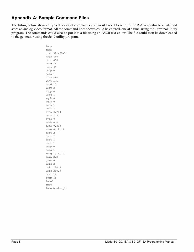
Appendix A: Sample Command Files The listing below shows a typical series of commands you would need to send to the ISA generator to create and store an analog video format. All the command lines shown could be entered, one at a time, using the Terminal utility program. The commands could also be put into a file using an ASCII text editor. The file could then be downloaded to the generator using the Send utility program.
fmtn fmtb hrat 31.469e3 hres 640 htot 800 hspd 16 hspw 96 hspp 0 hspg 1 vres 480 vtot 525 vspd 10 vspw 2 vspp 0 vspg 1 equb 0 equa 0 scan 1 avst 2 avss 0.700 avps 7.5 avpg 0 avsb 0.0 asss 0.300 assg 0, 1, 0 asct 2 dsct 2 dsst 1 ssst 1 cspp 0 cspg 1 xvsg 1, 1, 1 gama 2.2 gamc 0 usiz 2 hsiz 280.0 vsiz 210.0 dcex 14 dcbm 15 fmtg? fmte fmta Analog_3
Publication # 68-00155 (Rev: B 26-JULY-95) Page 9
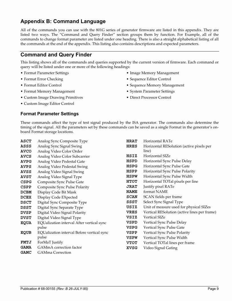
Appendix B: Command Language All of the commands you can use with the 801G series of generator firmware are listed in this appendix. They are listed two ways. The “Command and Query Finder” section groups them by function. For Example, all of the commands to change format parameter are listed under one heading. There is also a straight alphabetical listing of all the commands at the end of the appendix. This listing also contains descriptions and expected parameters.
Command and Query Finder This listing shows all of the commands and queries supported by the current version of firmware. Each command or query will be listed under one or more of the following headings:
• Format Parameter Settings
• Format Error Checking
• Format Editor Control
• Format Memory Management
• Custom Image Drawing Primitives
• Custom Image Editor Control
• Image Memory Management
• Sequence Editor Control
• Sequence Memory Management
• System Parameter Settings
• Direct Processor Control
Format Parameter Settings
These commands affect the type of test signal produced by the ISA generator. The commands also determine the timing of the signal. All the parameters set by these commands can be saved as a single Format in the generator’s on-board Format storage locations. ASCT Analog Sync Composite Type ASSS Analog Sync Signal Swing AVCO Analog Video Color Order AVCS Analog Video Color Subcarrier AVPG Analog Video Pedestal Gate AVPS Analog Video Pedestal Swing AVSS Analog Video Signal Swing AVST Analog Video Signal Type CSPG Composite Sync Pulse Gate CSPP Composite Sync Pulse Polarity DCBM Display Code Bit Mask DCEX Display Code EXpected DSCT Digital Sync Composite Type DSST Digital Sync Separate Type DVSP Digital Video Signal Polarity DVST Digital Video Signal Type EQUA EQUalization interval After vertical sync
pulse EQUB EQUalization interval Before vertical sync
pulse FMTJ ForMaT Justify GAMA GAMmA correction factor GAMC GAMma Correction
HRAT Horizontal RATe HRES Horizontal RESolution (active pixels per
line) HSIZ Horizontal SIZe HSPD Horizontal Sync Pulse Delay HSPG Horizontal Sync Pulse Gate HSPP Horizontal Sync Pulse Polarity HSPW Horizontal Sync Pulse Width HTOT Horizontal TOTal pixels per line JRAT Justify pixel RATe NAME format NAME SCAN SCAN fields per frame SSST Select Sync Signal Type USIZ Unit of measure used for physical SIZes VRES Vertical RESolution (active lines per frame) VSIZ Vertical SIZe VSPD Vertical Sync Pulse Delay VSPG Vertical Sync Pulse Gate VSPP Vertical Sync Pulse Polarity VSPW Vertical Sync Pulse Width VTOT Vertical TOTal lines per frame XVSG Video Signal Gating
Page 10 Model 801GC-ISA & 801GF-ISA Programming Manual
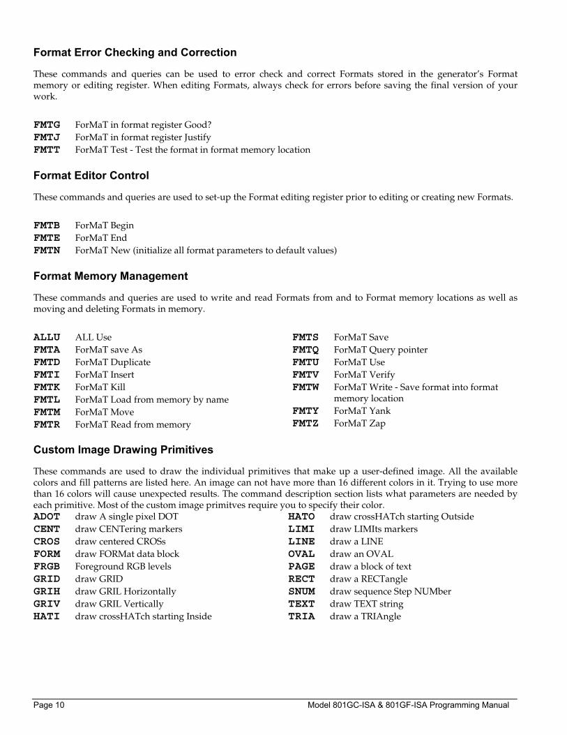
Format Error Checking and Correction
These commands and queries can be used to error check and correct Formats stored in the generator’s Format memory or editing register. When editing Formats, always check for errors before saving the final version of your work.
FMTG ForMaT in format register Good? FMTJ ForMaT in format register Justify FMTT ForMaT Test - Test the format in format memory location
Format Editor Control
These commands and queries are used to set-up the Format editing register prior to editing or creating new Formats.
FMTB ForMaT Begin FMTE ForMaT End FMTN ForMaT New (initialize all format parameters to default values)
Format Memory Management
These commands and queries are used to write and read Formats from and to Format memory locations as well as moving and deleting Formats in memory.
ALLU ALL Use FMTA ForMaT save As FMTD ForMaT Duplicate FMTI ForMaT Insert FMTK ForMaT Kill FMTL ForMaT Load from memory by name FMTM ForMaT Move FMTR ForMaT Read from memory
FMTS ForMaT Save FMTQ ForMaT Query pointer FMTU ForMaT Use FMTV ForMaT Verify FMTW ForMaT Write - Save format into format
memory location FMTY ForMaT Yank FMTZ ForMaT Zap
Custom Image Drawing Primitives
These commands are used to draw the individual primitives that make up a user-defined image. All the available colors and fill patterns are listed here. An image can not have more than 16 different colors in it. Trying to use more than 16 colors will cause unexpected results. The command description section lists what parameters are needed by each primitive. Most of the custom image primitves require you to specify their color. ADOT draw A single pixel DOT CENT draw CENTering markers CROS draw centered CROSs FORM draw FORMat data block FRGB Foreground RGB levels GRID draw GRID GRIH draw GRIL Horizontally GRIV draw GRIL Vertically HATI draw crossHATch starting Inside
HATO draw crossHATch starting Outside LIMI draw LIMIts markers LINE draw a LINE OVAL draw an OVAL PAGE draw a block of text RECT draw a RECTangle SNUM draw sequence Step NUMber TEXT draw TEXT string TRIA draw a TRIAngle
Publication # 68-00155 (Rev: B 26-JULY-95) Page 11
Colors, Fill Patterns and Fonts Avaialble for Custom Image Primitives
Available Colors:
Note: An image can not have more than 16 different colors in it. Trying to use more than 16 colors will cause unexpected results. Numbers at the end of the color name indicate the intensity level, as a percentage, of the color.
clear black red red50 red75 green green50 green75 yellow
yellow50 yellow75 blue blue50 blue75 magenta magenta50 magenta75 cyan
cyan50 cyan75 white brown gray3 gray5 gray7 gray10 gray13
gray17 gray20 gray23 gray25 gray27 gray30 gray33 gray37 gray40
gray43 gray47 gray48 gray50 gray51 gray53 gray57 gray60 gray63
gray67 gray70 gray73 gray75 gray77 gray80 gray83 gray87 gray90
gray93 gray95 gray97
These are special colors for use with TV outputs:
hueI hueQ huenegI huenegQ
These color names are used for elements in images that invert:
background foreground
Available Fill Patterns:
These patterns use a 16x16 block of dithered pixels with the number indicating the percentage of active pixels:
graypat0 graypat7 graypat13 graypat19
graypat25 graypat31 graypat38 graypat44
graypat50 graypat56 graypat63 graypat69
graypat75 graypat81 graypat88 graypat94
graypat100
These patterns create a checkerboard effect with the number indicating the size of each box in pixels:
checker1 checker2 checker4 checker8
These patterns create vertical and horizontal alternating bars with the number indicating the thicknes of the bars and the gap between them:
bars_V1 bars_V2
bars_V4 bars_V8
bars_H1 bars_H2
bars_H4 bars_H8
Special fill patterns: meme FCC_EMI
Custom Image Editor Control
These commands and queries are used to set-up the custom image editing register prior to editing or creating new test images.
IMGB custom IMaGe Begin IMGE custom IMaGe End
IMGN custom IMaGe New
Image Memory Management
These commands and queries are used to select test images that are drawn on the unit under test. The current version of the firmware does not allow adding user-defined images to the built-in images. ALLU ALL Use IMGA IMaGe save As IMGK IMaGe Kill IMGL IMaGe Load
IMGQ IMaGe Query pointer IMGR IMaGe Read image from image memory
location IMGU IMaGe Use (draw image)
Page 12 Model 801GC-ISA & 801GF-ISA Programming Manual
Sequence Parameter Settings
These commands and queries are used for creating a new sequence.
DNUM Display sequence step NUMber SMOD Sequence MODe SDLY sequence Step DeLaY
SEQB SEQuence description Begin SEQE SEQuence description End SEQN SEQuence description New
Sequence Memory Management
These commands and queries are used to select test images that are drawn on the unit under test. The current version of the firmware does not allow adding user-defined images to the built-in images.
SEQA SEQuence save As SEQK SEQuence Kill SEQL SEQuence Load
SEQQ SEQuence Query pointer SEQU SEQuence Use STEP go to sequence STEP #
System Parameter Settings
These commands and queries are used to set system level parameters that affect all Formats and Images:
ASSC Analog Sync Swing Calibration factor ASSC Analog Sync Swing Calibration factor AVCM Analog Video Calibration Method AVSC Analog Video Swing Calibration factor CALF analog video CALibration Factors DCRD Display Code ReaD INIT INITialize generator IVER Image VERsion
KEYY KEY toggle LCDS LCD Status LEDS LED Status MSIZ LightMeter SIZe OUTG OUTputs Gate RATC clock RATe Calibration factor UIDN User IDeNtification USIZ Unit of measure used for physical SIZes
Miscellaneous System Parameters
The queries in this category are used to help identify the exact configuration of the generator.
*IDN IDeNtification (listed under “I”) VERF VERsion of Firmware
VERH VERsion of Hardware
Direct Processor Control (Reserved)
These commands and queries are used to communicate directly with the generator’s microprocessor and its internal functions. They are reserved for system de-bugging and diagnostics by Quantum Data personnel as well as for special software applications developed by Quantum Data.
❖ Indiscriminate use of these commands can cause the generator to malfunction. An irreversible loss of user-programmed data may also occur.
ADDR ADDRess BASE BASE (radix) BOOT warm BOOT CACH instruction CACHe enable CALL CALL internal function
GETA GET data from Absolute memory location GETR GET data from Relative memory location PUTA PUT Absolute PUTR PUT Relative SIZE SIZE of bit field
Publication # 68-00155 (Rev: B 26-JULY-95) Page 13
Command Summary in Alphabetical Order ADDR <address>
Limits: <address> 0 to 4,294,967,295 (BASE = 10) -2,147,483,648 to 2,147,483,647 (BASE = -10) 0 to FFFFFFFF (BASE = 16) -80000000 to 7FFFFFFF (BASE = -16)
Description: The ADDR command sets the pointer register that is used in connection with the PUTR command and GETR? query. The ADDR? query returns the current contents of the pointer register. The ADDR and ADDR? instructions expect and return parameters formatted according to the current radix, respectively (see the BASE command for details).
ADOT <color1> <x> <y>
Description: Draws a single pixel dot of the given color at the given x,y position.
ALLU
Description: The ALLU command first reconfigures the signal generating hardware in accordance with the current settings of the parameters in the format register. Next, the current test image is re-rendered using the latest system and format parameter data.
ASCT <type>
Limits: <type> 0=none 1=American HDTV ORed 2=American ORed 3=American w/serr 4=American w/serr & eq 5=European HDTV ORed 6=European ORed 7=European w/serr 8=European w/serr & eq 9=American HDTV w/serr 10=American HDTV w/serr & eq 11=European HDTV w/serr 12=European HDTV w/serr & eq 13=Japanese HDTV ORed 14=Japanese HDTV w/serr 15=Japanese HDTV w/serr & eq
Description: The ASCT command establishes the kind of composite sync that is added to the analog video outputs when analog sync is enabled (see SSST command) and an analog video signal is being generated (see AVST command). The ASCT? query returns the current setting of ASCT. A setting of zero (0) indicates that the “ACS” sync enable button can not be activated by the operator.
Page 14 Model 801GC-ISA & 801GF-ISA Programming Manual
ASSC <red factor>, <green factor>, <blue factor>
ASSC <common factor>
Limits: <factor> (floating point accepted) min = 0.000 max = 1.000
Description: The ASSC command sets the analog video calibration (or scaling) factor that is used to adjust the level set by ASSS. Issuing the command with a single factor sets all three analog video channels to the same value. Issuing the command with three factors sets each of the analog video channels to each of the given values. The actual peak-to-peak swing of the analog composite sync signals at the output connectors is equal to the product of: ASSS multiplied by ASSC. The ASSC? query returns the current settings of ASSC. The default factory setting is 1.000 for this parameter.
❖ The ASSC parameter is a system level parameter that will affect the analog video swing of all Formats that are recalled. The ASSC value will be retained when the generator is powered down and back up again. Query the current setting of ASSC if you are experiencing problems with low or missing analog composite sync levels.
ASSG <red mode>, <green mode>, <blue mode>
ASSG <common mode>
Limits: <red mode> <green mode> <blue mode> <common mode> 0 = OFF 1 = ON
Description: The ASSG command enables and disables adding composite sync to all three analog video outputs when analog sync is selected (see SSST command) and an analog video signal is being generated (see AVST command). This command can take the place of sending all three of the individual ASRG, ASGG and ASBG commands. The ASSG? query returns the current settings of ASSG.
ASSS <level>
Limits: <level> > (floating point accepted) min = 0.000 volts max = 0.400 volts
Description: The ASSS command sets the maximum peak-to-peak swing for any composite sync that is added to any of the three analog video channels. The actual peak-to-peak swing of the analog sync signals at the output connectors is equal to the product of: ASSS multiplied by ASSC. The ASSS? query returns the current setting of ASSS.
AVCM <type>
Limits: <type> 0 = Interpolate 1 = Measure_Interpolate 2 = Measure_SetAbsolute 3 = Test_Levels
Description: Analog Video Calibration Method
Publication # 68-00155 (Rev: B 26-JULY-95) Page 15
AVCO <type>
Limits: <type> 0 = RGB (Normal) 1 = RBG R>R B>G G>B 2 = GRB G>R R>G B>B 3 = GBR G>R B>G R>B 4 = BRG B>R R>G G>B 5 = BGR B>R G>G R>B (Apple 15" on 13W3)
Description: Changes which analog video channel is used for a particular color
AVCS <type>
Limits: <type> 0 = No subcarrier 1 = NTSC_M 2 = NTSC_443 3 = PAL_BD 4 = PAL_N
Description: Analog video color sub-carrier selection (Not used on 801GC or 801GC-ISA)
AVPG <mode>
Limits: <mode> 0 = OFF 1 = ON
Description: The AVPG command enables and disables the analog video setup pedestal when an analog video signal is being generated (see AVST command). The AVPG? query returns the current setting of AVPG.
AVPS <level>
Limits: <level> min = max =
Description: Analog video pedestal swing
AVSC <red factor>, <green factor>, <blue factor>
AVSC <common factor>
Limits: <factor> (floating point accepted) min = 0.000 max = 1.000
Description: The AVSC command sets the analog video calibration (or scaling) factor that is used to adjust the level set by AVSS. Issuing the command with a single factor sets all three analog video channels to the same value. Issuing the command with three factors sets each of the analog video channels to each of the given values. The actual peak-to-peak swing of the analog video signals at the output connectors is equal to the product of: AVSS multiplied by AVSC. The AVSC? query returns the current setting of AVSC for each channel. The default factory setting is 1.000 for this parameter.
❖ The AVSC parameter is a system level parameter that will affect the analog video swing of all Formats that are recalled. The AVSC value will be retained when the generator is powered down and back up again. Query the current setting of AVSC if you are experiencing low or missing analog video levels.
Page 16 Model 801GC-ISA & 801GF-ISA Programming Manual
AVSS <level>
Limits: <level> > (floating point accepted) min = 0.000 volts max = 0.715 volts
Description: The AVSS command sets the maximum peak-to-peak swing for all three analog video channels. The actual peak-to-peak swing of the analog video signals at the output connectors is equal to the product of: AVSS multiplied by AVSC. The AVSS? query returns the current setting of AVSS.
AVST <type>
Limits: <type> 0=none 1=Analog Y (grayscale) 2=Analog RGB (color) 3=Analog TV Y (grayscale) 4=Analog TV EYC (color subcarrier) 5=Analog YPrPb (color difference) Must be zero (0) when any digtal video type is selected (DVST ? 0).
Description: The AVST command establishes the type of signal that appears on the analog video outputs of the generator. The AVST? query returns the current setting of AVST.
BASE <radix>
Limits: <radix> = 0 to 36
Description: The BASE command establishes the radix of address and data parameters passed-to or returned-from the ADDR, GETA, GETR, PUTA, PUTR, and CALL instructions. If a negative radix is specified, then parameters passed (or returned) from these functions are assumed to be signed. For example, if BASE= -16, then the value -1 is used to communicate the value FFFFFFFF hex. The BASE? query returns the current setting of BASE. The radix <radix> is always passed and returned in base 10, regardless of the setting of BASE. BASE is preset to -10 each time the generator is powered on. Base -10 is the preferred radix. The BASE? query returns the current setting of BASE.
BOOT
Description: Warm Boot
CACH <mode>
Limits: <mode> 0 = OFF 1 = ON
Description: Instruction Cache Enable
CALF <Video 1000> <Video 700> <Sync 400> <Sync 40> <NTSC714> <PAL700>
Limits:
Description: Analog video calibration factors
Publication # 68-00155 (Rev: B 26-JULY-95) Page 17
CALL <address> <passed> [ <p(1)> [ <p(2)> [ <p(3)> ...[ <p(18)> ]...]]]
Limits: <address> 0 to 4,294,967,295 (BASE = 10) -2,147,483,648 to 2,147,483,647 (BASE = -10) 0 to FFFFFFFF (BASE = 16) -80000000 to 7FFFFFFF (BASE = -16)
<passed> 0 to 18 (BASE = -10 or 10) 0 to 12 (BASE = -16 or 16)
<returned> (query only) 4,294,967,295 and 0 to 20 (BASE = 10) -1 to 20 (BASE = -10) FFFFFFFF and 0 to 14 (BASE = 16) -1 to 14 (BASE = -16 query only)
<p(n)> 0 to 4,294,967,295 (BASE = 10) -2,147,483,648 to 2,147,483,647 (BASE = -10) 0 to FFFFFFFF (BASE = 16) -80000000 to 7FFFFFFF (BASE = -16)
Description: The CALL command can be used to call internal C functions. Address <address> is the entry point of the C function to be called. Parameter <passed> indicates the number of parameters to be passed. If <passed> is non-zero, then parameters being passed <p(1)> thru <p(n)> immediately follow the <passed> parameter on the command line. The CALL? query is similar to the CALL command except that returned parameters are expected. Here, a third parameter <returned> is added to indicate the number of parameters that will be returned by the function. If BASE= -10 or -16 and a <returned> value of -1 is given (4,294,967,295 if BASE=10 or FFFFFFFF if BASE=16), then a single value will be read from register A8 of the TMS34010 (rather than being popped off the C stack). Most C functions that return a single parameter will return their single parameter in this way. Returned parameters are space-delimited and formatted according to the current radix (see BASE command). All parameters passed to the CALL and CALL? must be formatted according to the current radix. This includes the parameters <passed> and <returned>.
CENT <color1>
Description: Draws markers that define the center of active video using the given color1.
CROS <color1>
Description: Draws a centered cross using the given color1.
CSPG <mode>
Limits: <mode> 0 = OFF 1 = ON
Description: The CSPG command enables and disables all of the digital composite sync outputs when digital composite sync is selected via the SSST command (SSST = 3). The CSPG? query returns the current setting of CSPG.
CSPP <polarity>
Limits: <polarity> 0 = active-low (negative going pulse) 1 = active-high (positive going pulse)
Description: The CSPP command establishes the logic sense of the digital composite sync outputs when they are enabled via the SSST, CSPG, HSPG, and (or) VSPG commands. The CSPP? query returns the current setting of CSPP.
Page 18 Model 801GC-ISA & 801GF-ISA Programming Manual
DCBM <mask>
Limits: <mask> 0 = 0 0 0 0 8 = 1 0 0 0 1 = 0 0 0 1 9 = 1 0 0 1 2 = 0 0 1 0 10 = 1 0 10 3 = 0 0 1 1 11 = 1 0 1 1 4 = 0 1 0 0 12 = 1 1 0 0 5 = 0 1 0 1 13 = 1 1 0 1 6 = 0 1 1 0 14 = 1 1 1 0 7 = 0 1 1 1 15 = 1 1 1 1
Description: The DCBM command sets the 4-bit binary bit mask used by the DCEX? query. The DCBM? query returns the current setting of DCBM.
DCEX <code#>
Limits: <code#> 0 = 0 0 0 0 8 = 1 0 0 0 1 = 0 0 0 1 9 = 1 0 0 1 2 = 0 0 1 0 10 = 1 0 1 0 3 = 0 0 1 1 11 = 1 0 1 1 4 = 0 1 0 0 12 = 1 1 0 0 5 = 0 1 0 1 13 = 1 1 0 1 6 = 0 1 1 0 14 = 1 1 1 0 7 = 0 1 1 1 15 = 1 1 1 1
Description: The DCEX command sets up the display code that is expected from a display connected to the generator. The code is determined by one or more “sense” lines being connected to ground by the display. Many video controller cards for the Apple Macintosh II and VGA type cards for the IBM-PC sample the status of the display code sense lines. The information is then used to set-up one of several different operating modes to match a particualr display. An improper display code may make the controller card or display appear to be malfunctioning. The “Making Connection” chapter has information on display codes that are used by some systems.
The DCEX? query first performs a logical AND operation with the display code bit mask and the actual display code that is sensed. The decimal equivalent of the result is then returned. The mask is set with the DCEX command.
The expected setting and the actual result are both shown in the “Format” test image. They have no effect how a given format generates a set of test signals.
DCRD?
Query Response: <code#>
Description: Returns mask display code read from monitor sense leads.
DNUM <mode>
Limits: <mode> 0 = Disable 1 = Enable
Description: Command enables/disables sequence step number display. Query returns the current step number display mode.
Publication # 68-00155 (Rev: B 26-JULY-95) Page 19
DSCT <type>
Limits: <type> 0=none 1=American HDTV ORed 2=American ORed 3=American w/serr 4=American w/serr & eq 5=European HDTV ORed 6=European ORed 7=European w/serr 8=European w/serr & eq 9=American HDTV w/serr 10=American HDTV w/serr & eq 11=European HDTV w/serr 12=European HDTV w/serr & eq 13=Japanese HDTV ORed 14=Japanese HDTV w/serr 15=Japanese HDTV w/serr & eq
Description: The DSCT command establishes the type of composite sync that appears at the digital composite sync outputs when digital composite sync is selected via the SSST command. The DSCT? query returns the current setting of DSCT. A setting of zero (0) indicates that the “DCS” sync enable button can not be activated by the operator.
DSST <type>
Limits: <type> 0=none 1=American separate 2=American HDTV separate 3=European HDTV separate 4=Japanese HDTV separate 5=European separate
Description: The DSST command establishes the type of digital separate sync that appears at the digital HS & VS outputs of the generator when digital composite sync is selected via the SSST command and the outputs are gated on via the HSPG and VSPG commands. The only difference between EIA and CCIR digital separate syncs is that, in the case of CCIR, the width of the vertical sync pulse is 0.5 line shorter than the width specified via the VSPW command. In the EIA case, the width of the vertical sync pulse is as programmed. The DSST? query returns the current setting of DSST. A setting of zero (0) indicates that the “DHS & DVS” sync enable button can not be activated by the operator.
DVSP <polarity>
Limits: <polarity> 1 = active-high (positive going pulse)
Description: The DVSP command establishes the logic sense of the digital video outputs. Polarity must be set to active-high on the generator, otherwise an error will be reported. The DVSP? query returns the current setting of DVSP.
Page 20 Model 801GC-ISA & 801GF-ISA Programming Manual
DVST <type>
Limits: <type> 0 = not used 1 = one-bit B/W 2 = two-bit B/W (MDA) 5 = RGB 6 = RGBI (CGA) 7 = RrGgBb (EGA) Must be zero (0) when any analog video type is selected (AVST ? 0).
Description: The DVST command establishes the kind of video signal that exits the digital video signal outputs of the generator. The DVST? query returns the current setting of DVST. DOES NOT APPLY TO THE ISA VERSIONS OF THE GENERATOR
EQUA <lines>
Limits: <lines> min = 0 max = number of lines after vertical sync before video
Description: The EQUA command establishes the width of the equalization interval after the vertical sync pulse in each field whenever a serrated & equalized sync type is selected via either ASCT or DSCT commands and selected via the SSST command. If the type specified for the selected sync signal is one of the CCIR types, then the actual equalization interval output by the generator will be 0.5 lines shorter than the whole number specified. The EQUA? query returns the current setting of EQUA.
EQUB <lines>
Limits: <lines> min = 0 max = number of lines after video and before vertical sync
Description: The EQUB command establishes the width of the equalization interval before the vertical sync pulse in each field whenever a serrated & equalized sync type is selected via either ASCT or DSCT commands and selected via the SSST command. If the type specified for the selected sync signal is one of the CCIR types, then the actual equalization interval output by the generator will be 0.5 lines shorter than the whole number specified. The EQUB? query returns the current setting of EQUB.
FMTA <name>
Limits: <name> = a valid MS-DOS filename (8 characters minus any extension)
Description: Format save as < Name >
FMTB
Description: The FMTB command is used to mark the beginning of a format editing session. It switches context to that of editing a format, thereby making the format editing commands available (this command does nothing in the current firmware version, but should be used for compatibility with future versions of firmware).
Publication # 68-00155 (Rev: B 26-JULY-95) Page 21
FMTD <first> <last> <destination>
Limits: <first>, <last> -1 thru -24 (EPROM) or 1 thru 300 (RAM)
<destination> 1 thru 300 (RAM)
Description: The FMTD command copies a contiguous range of formats beginning with memory location <first> and continuing thru location <last> to an area of format memory beginning at location <destination>. Source and destination areas may overlap, but may not be identical. Locations not overwritten with new data are left unchanged by this command. If duplicate copies are not desired, then the FMTM command should be used instead of this one.
FMTE
Description: The FMTE command is used to mark the end of a format editing session. It switches context away from that of editing a format by hiding the format editing commands (this command does nothing in the current firmware version, but should be used for compatibility with future versions of firmware).
FMTG?
Query Response: <test result>
Description: The FMTG? query tests the format in the format register for errors. If no errors are found, FMTG? returns zero. Otherwise, if one or more errors exist, FMTG? returns the number of the first error encountered (see “Error Messages” appendix for the cause and cure associated with each error number). To test formats residing in format memory, use the FMTT? query.
FMTI <location>
Limits: <location> 1 thru 300 (RAM)
Description: The FMTI command first moves formats up one position starting at location <location>. Then FMTI inserts (copies) the format in the format register into the format memory location <location>. The format residing in the top-most format memory location before the FMTI command is given is discarded in the process.
FMTJ
Description: Justify format in buffer. The justification routine will reduce the Horizontal Total as is necessary to put the pixel rate at the JRAT and adjust the other horizontal timing parameters by the same factor.
FMTK <name>
Limits: <name> = a valid MS-DOS filename (8 characters minus any extension)
Description: Format Kill by name command. Query returns location if named format can be deleted. If format is read-only, then query returns zero.
Page 22 Model 801GC-ISA & 801GF-ISA Programming Manual
FMTL <name>
Limits: <name> = a valid MS-DOS filename (8 characters minus any extension)
Description: The FMTL command reads the format having a name equal to name <name> from format memory (or EPROM) into the format register. FMTL does not re-configure the signal generating hardware. This feature allows you to work on the contents of any format memory location, while continuing to output a signal based on a previously used format (see FMTU command). The FMTL? query returns the location <location> in which a format having a name equal to <name> is found. If multiple formats exist having name <name>, then the lowest numbered location containing a format with a matching name <name> is returned. The format memory (RAM) is always searched first. If a format with name <name> cannot be found anywhere in the format memory, then the industry-standard formats located in EPROM (negative locations) are searched next.
FMTM <first> <last> <destination>
Limits: <first>, <last>, <destination> 1 thru 300 (RAM)
Description: The FMTM command moves formats in format memory beginning with location <first > and continuing thru location <last> to another area of memory beginning at location <destination>. Source and destination areas may overlap, but may not be the same. Non-overlapping source locations are zapped (erased) after formats have been moved. To leave the source locations intact, use the FMTD command instead of this one.
FMTN
Description: The FMTN command initializes the format editing register. Sending this one command is equivalent to sending all of the following commands: ASBG ø XVSG 1, 1, 1 GAMA 2.2 SCAN 1 ASCT 1 CSPG 1 GAMC ø SSST 1 ASGG 1 CSPP ø HRAT ø USIZ 2 ASSG ø, 1, 0 DCBM ø HRES ø VRES ø ASSS ø.286 DSEX ø HSIZ 280 VSIZ 210 AVPG ø DSST 1 HSPD ø VSPD ø AVPS ø.ø DVSP ø HSPG 1 VSPG 1 AVSB ø.ø DVST ø HSPP ø VSPP ø AVSS ø.714 EQUA ø HSPW ø VSPW ø AVST ø EQUB ø HTOT ø VTOT ø
This should be the first command sent to the generator when downloading a new format. The command only resets the register to a known state. The command does not create a usable format. After the FMTN command has been sent, the commands FMTB, HRAT, HRES, HTOT, VRES, VTOT, VSPW, AVST (or DVST), and FMTE must be executed before the new format is used, otherwise a format error will result.
FMTQ? <index> <number>
Description: The format pointer query reads in a knob list of formats starting at <index> and will read in <number> of format names. Used to read knob lists.
FMTR <location>
Limits: <location> = 1 thru 300 (RAM) or -1 thru -24 (EPROM)
Description: Read format from the format memory location into the format register. The FMTR command does not re-configure the signal generating hardware. This feature allows the contents of the format register to be worked on, while a signal, based on a previously used format, continues to be output (see FMTU command). The FMTR? query returns the <name> of the format stored in location <location>. FMTR? returns the string “EMPTY” if the format memory location <location> is empty.
Publication # 68-00155 (Rev: B 26-JULY-95) Page 23
FMTS
Description: Saves format back to its original location
FMTT? <location>
Limits: <location> = 1 thru 300 (RAM) or -1 thru -24 (EPROM)
Query Response: <test result> 0 if OK number of first error encountered if bad
Description: The FMTT? query tests the information in the format memory location <location> for errors. If no errors are found, then FMTT? returns zero. Otherwise, FMTT? returns the number of the first error encountered (see the “Error Messages” appendix for the cause and cure associated with each error number). To test the information content of the format register, refer to the FMTG? query. Note that the FMTT? query does not test for corrupted data (i.e lost bits). See the FMTK? query for more information on checking the integrity of format memory locations.
FMTU
Description: The FMTU command re-configures the signal generating hardware in accordance with the current contents of the format register. The FMTU? query returns name of format currently driving output hardware
FMTV? <location>
Limits: <location> = 1 thru 300 (RAM) or -1 thru -24 (EPROM)
Query Response: <test result> 0 = OK 1 = Data Corrupted
Description: Verifies integrity of data stored in a format. Does not check for errors.
FMTW <location>
Limits: <location> = 1-300
Description: The FMTW command writes the contents of the format register into the specified format memory location <location>.
FMTY <location>
Limits: <location> = 1-300
Description: The FMTY command first yanks (erases) the format currently stored at format memory location <location>. It then moves all formats above that location down one to fill in the gap. The top-most format memory location is zapped (erased) after its contents have been moved.
FMTZ <first> <last>
Limits: <first>, <last> = 1-300
Description: The FMTZ command zaps (erases) formats in format memory beginning with location <first> and continuing thru location <last>. To zap a single location, make <first> and <last> equal. The FMTZ? query can be used to determine if a location has been zapped (erased).
FORM <color1> <x> <y>
Description: Draws a block of text, of the given color and at the given x,y position, with information about the current format.
Page 24 Model 801GC-ISA & 801GF-ISA Programming Manual
FRGB <red factor>, <green factor>, <blue factor>
FRGB <common grey factor>
Limits: <factor> min = 0 max = 255
Description: Temporarily sets foreground to given color levels. Not global and not saved.
GAMA <factor>
Limits: <factor> = non-zero value (floating point accepted)
Description: The GAMA command establishes the current analog video gamma correction factor. In order to apply any gamma correction to the format, the GAMC parameter must be turned on. The GAMA? query returns the current setting of the gamma correction factor.
GAMC <mode>
Limits: <mode> 0 = don’t correct (correction off) 1 = correct (correction on)
Description: The GAMC command enables or disables application of the analog video gamma correction factor. The GAMC? query can be used to determine if the gamma correction factor is currently being applied.
GETA? <address>
Limits: <address> 0 to 4,294,967,295 (BASE = 10) -2,147,483,648 to 2,147,483,647 (BASE = -10) 0 to FFFFFFFF (BASE = 16) -80000000 to 7FFFFFFF (BASE = -16)
Query Response: <value>
Description: The GETA? query returns the value of the data stored at the memory <address> specified. Up to 32 bits can be read with this query (see SIZE command). The returned value <value> is formatted according to the current setting of BASE (see the BASE command).
GETR?
Query Response: <value>
Description: The GETR? query returns the value of the data stored at the memory location currently pointed to by the address register (see ADDR command). Up to 32 bits can be read with this query (see SIZE command). The returned value <value> is formatted according to the current setting of BASE (see the BASE command). The address register is automatically incremented by SIZE bits after the current location has been read.
GRID <color1> <x-boxes> <y-boxes>
Description: Draws a grid of the given color. The grid forms the given number of boxes in each direction.
GRIH <color1> <width on> <width off>
Description: Draws a horizontal series of full height bars of the given color. The bars are drawn with the given width and spacing between the bars.
GRIV <color1> <width on> <width off>
Description: Draws a vertical series of full width bars of the given color. The bars are drawn with the given height and spacing between the bars.
Publication # 68-00155 (Rev: B 26-JULY-95) Page 25
HATI <color1> <x-boxes> <y-boxes>
Description: Draws a crosshatch of the given color. The crosshatch forms the given number of boxes in each direction.
HATO <color1> <x-boxes> <y-boxes>
Description: Draws a crosshatch of the given color. The crosshatch forms the given number of boxes in each direction.
HRAT <frequency in Hz>
Limits: <frequency in Hz> 8000-100000 (floating point accepted)
Description: The HRAT command sets the line frequency. Pixel rate is equal to the product: HTOT times HRAT. Frame rate is equal to the quotient: HRAT divided by VTOT. Field rate is equal to the product: SCAN times the frame rate. The HRAT? query returns the current horizontal frequency setting.
HRES <pixels>
Limits: <pixels> = number of active pixels
Description: The HRES command establishes the number of active pixels per line. The HRES? query returns the current setting of HRES.
HSIZ <physical size>
Limits: <physical size> = positive value (floating point accepted)
Description: (context sensitive - see FMTB and FMTE) The HSIZ command establishes the horizontal physical size of the image on the display. Units expected (or returned) vary according to the last mode set with USIZ command. The HSIZ command is context sensitive and must appear between begin and end commands: FMTB and FMTE. The HSIZ? query returns the current setting of HSIZ.
❖ Make sure that the USIZ parameter is properly set before using the HSIZ command. Changing the USIZ setting after entering HSIZ will convert the size to match the new unit of measure.
HSPD <pixels>
Limits: <pixels> =
Description: The HSPD command establishes the delay between the leading edge of blanking and the leading edge of the horizontal sync pulse. The HSPD? query returns the current setting of HSPD.
HSPG <mode>
Limits: <mode> 0 = OFF 1 = ON
Description: The HSPG command enables and disables all of the digital horizontal sync outputs. If digital composite sync is selected (see SSST command) and HSPG=1, then composite sync will be output on both the HS-BNC and the HS pin of the VGA D-sub connector in addition to the CS pins of the MAC & PGA D-sub connectors. The HSPG? query returns the current HSPG mode <mode>.
Page 26 Model 801GC-ISA & 801GF-ISA Programming Manual
HSPP <polarity>
Limits: <polarity> 0 = active-low (negative going pulse) 1 = active-high (positive going pulse)
Description: The HSPP command establishes the logic sense of the digital horizontal sync outputs. Setting polarity to 1 causes the leading edge of horizontal sync to be a low-to-high transition. Setting polarity to 0 causes the leading edge of horizontal sync to be a high-to-low transition. The HSPP? query returns the current polarity of HSPP.
HSPW <pixels>
Limits: <pixels> = width of pulse in pixels
Description: The HSPW command establishes the width of the horizontal sync pulse. The HSPW? query returns the current setting of HSPW.
HTOT <pixels>
Limits: <pixels> = number of pixels per line
Description: The HTOT command establishes the total number of pixels per horizontal line. The HTOT? query returns the current setting of HTOT.
The pixel rate is equal to the product of: HRAT multiplied by HTOT.
❖ The current version of the firmware does not allow you to directly enter a specific pixel rate when setting up a format. If your test specifications call for a specific pixel or dot clock rate, enter suitable values for HRAT and HTOT to give you the desired pixel rate.
*IDN?
Query Response: QuantumData,<model#>,0,<firmware version #>
Description: The *IDN? query returns an equipment identification string formatted per IEEE-488.2 standards.
IMGA <name>
Limits: <name> = a valid MS-DOS filename (8 characters minus any extension)
Description: Image save as < Name >
IMGB
Description: The IMGB command is used to mark the beginning of a image editing session. It switches context to that of editing a image, thereby making the image editing commands available.
IMGE
Description: The IMGE command is used to mark the end of a image editing session. It switches context away from that of editing a image by hiding the image editing commands.
IMGK <name>
Limits: <name> = a valid MS-DOS filename (8 characters minus any extension)
Description: Image Kill by name command. Query returns location if named image can be deleted. If image is read-only, then query returns zero.
IMGN
Description: The IMGN command initializes the image editing register.
Publication # 68-00155 (Rev: B 26-JULY-95) Page 27
IMGL <name>
Limits: <name> = a valid MS-DOS filename (8 characters minus any extension)
Description: The IMGL command reads the image having a name equal to name <name> from memory into the image register.
IMGQ? <index> <number>
Description: The image pointer query reads in a knob list of images starting at <index> and will read in <number> of image names. Used to read knob lists.
IMGR <location>
Limits: <location> -1 thru -26 (EPROM)
Description: The IMGR command copies the image residing in the image memory with location <location> into the image register. The IMGR command does not cause the selected image to be drawn. See the IMGU command for actually drawing the image.
IMGU
Description: The IMGU command draws an image based on the current contents of the image register. The IMGU? query returns the image memory location <location> from which the current contents of the image register were read. See the IMGR command for setting the contents of the image register.
INIT
Description: Initializes all memory in the generator to factory default conditions and runs the self calibration cycle.
❖ The INIT command erases all user created formats, images and sequences stored in the generator. There is no way to undo the use of this command.
IVER <mode>
Limits: <mode> 0 = Normal 1 = Invert or display alternate version
Description: The IVER command selects which version of the current image will be drawn when either an ALLU or IMGU command is executed. The IVER? query returns returns the current setting of IVER.
JRAT <frequency in MHz>
Limits: <frequency in MHz> ??? -??? (floating point accepted)
Description: Justifies the pixel rate
Page 28 Model 801GC-ISA & 801GF-ISA Programming Manual
KEYY <button #>
Limits: <button #> 1 = Image/Step 2 = Red 3 = Green 4 = Blue 5 = ACS 6 = DCS 7 = DSS 8 = Outputs
Description: Toggles the status of the Image version, R / G / B video gating, ACS / DCS / DSS Sync gating and Outputs gating.
LCDS?
Query Response: Two lines of text strings
Description: The text strings represent what would be displayed on the LCD of the stand alone box version of the generator.
LEDS?
Query Response: 0-255
Description: The binary (base 2) equivalent of the returned decimal number represents the current status of the Image version, R / G / B video gating, ACS / DCS / DSS Sync gating and Outputs gating.
MODE
Description: Normally used on the stand alone box version of the generator to set its communications parameters.
LIMI <color1>
Description: Draws markers that define the edges of active video using the given color1.
LINE <color1> <x1> <y1> <x2> <y2>
Description: Draws a one pixel thick line of the given color between the two given endpoints.
MSIZ <width>, <height>
MSIZ <common size> (for a square box)
Limits: <size> = positive floating point number.
Description: The MSIZ command establishes the physical size of the lightmeter box(es) displayed in the BriteBox test image. The unit of measure used is based on the current setting of the system level USIZ parameter. It also affects the size of the cursor boxes in the Persist image. The MSIZ? query returns the current settings of MSIZ based on the current setting of the system level USIZ parameter.
NAME <name string>
Limits: <name string> = a valid MSDOS filename (8 characters without any extension)
Description: (context sensitive - see FMTB and FMTE) The NAME command establishes the name associated with the format being edited. The NAME command is context sensitive and must appear between the begin and end commands (e.g FMTB and FMTE).
Publication # 68-00155 (Rev: B 26-JULY-95) Page 29
OUTG <mode>
Limits: <mode> 0 = OFF 1 = ON
Description: The OUTG command gates all video and sync outputs of the generator ON and OFF. Gating the outputs OFF forces all outputs to be turned off. Gating the outputs ON turns on all outputs whose individual gating settings are turned ON. The OUTG? query returns the current status of the outputs of the generator.
OVAL <color1> <width> <height> <x> <y> [ <fill> ]
Description: Draws an oval of the given color1, width and height. The oval’s x,y position is specified as the top left corner of its framing rectangle. It is drawn as an outline unless a fill pattern is specified.
PAGE <color1> <width> <height> <x> <y> <fontname> <character> [ <fill>]
Description: Draws a block of a single repeating character of the given color1, font and character code. The block is of the given width and height. The block’s x,y position is specified for its top left corner.
PCSG < mode>
Limits: < mode> 0 = OFF 1 = ON
Description: The PCSG command enables and disables the pixel clock output.
PUTA <address> <value>
Limits: <address> 0 to 4,294,967,295 unsigned decimal (BASE = 10) -2,147,483,648 to 2,147,483,647 (BASE = -10) 0 to FFFFFFFF (BASE = 16) -80000000 to 7FFFFFFF (BASE = -16)
<value> 0 to 2^(SIZE)-1
Description: The PUTA command writes the specified value <value> into memory at the specified address <address>. The two parameters <address> and <value> are interpreted according to the current setting of BASE (see the BASE command). The number and format of the bits written depend on the current setting of SIZE (see the SIZE command).
PUTR <value>
Limits: <value> = 0 to 2^(SIZE)-1
Description: The PUTR command writes the specified value <value> into the location pointed to by the address register (see the ADDR command). The parameter <value> is interpreted according to the current setting of BASE (see the BASE command). The number and format of the bits written depend on the current setting of SIZE (see the SIZE command). The address register is automatically incremented by SIZE bits after the current location has been written to.
RATC <factor)
Limits: <factor> = positive floating point number. Typical range 0.99990 through 1.00010
Description: Rate calibration factor.
Page 30 Model 801GC-ISA & 801GF-ISA Programming Manual
RECT <color1> <width> <height> <x> <y> [ <fill> ]
Description: Draws a rectangle of the given color1, width and height. The rectangle’s x,y position is specified at its top left corner. It is drawn as an outline unless a fill pattern is specified.
SCAL
Description: Causes generator to go through its self calibration cycle.
SCAN <fields>
Limits: <fields> 1 = progressive (non-interlace) 2 = interlace
Description: The SCAN command establishes the number of fields scanned per frame. Set to 1 for progressive (non-interlaced) scan and 2 for interlaced scan. The SCAN? query returns the current setting of SCAN.
SDLY <delay>
Limits: <delay> (floating point accepted)
Description: Sequenc e step delay time.
SEQA <name>
Limits: <name> = a valid MS-DOS filename (8 characters minus any extension)
Description: Sequence save as < Name >
SEQB
Description: The SEQB command is used to mark the beginning of a sequence editing session. It switches context to that of editing a sequence, thereby making the sequence editing commands available.
SEQE
Description: The SEQE command is used to mark the end of a sequence editing session. It switches context away from that of editing a sequence by hiding the sequence editing commands.
SEQK <name>
Limits: <name> = a valid MS-DOS filename (8 characters minus any extension)
Description: Sequence Kill by name command. Query returns location if named sequence can be deleted. If sequence is read-only, then query returns zero.
SEQL <name>
Limits: <name> = a valid MS-DOS filename (8 characters minus any extension)
Description: Command loads sequence into buffer by name. Command will set name to NULL if name is not given. Query returns name of sequence in buffer.
SEQN
Description: The SEQN command initializes the sequence editing register.
SEQQ?
Description: The sequence pointer query reads in a sequence list of sequence sstarting at <index> and will read in <number> of sequence names. Used to read knob lists.
Publication # 68-00155 (Rev: B 26-JULY-95) Page 31
SEQU
Description: Command causes sequence in buffer to be used and sequence user interface to appear. If name in buffer is NULL, then the normal user interface is returned. Query returns name of sequence currently being used.
SIZE <size>
Limits: <size> -32 to -1 or 1 to 32 bits
Description: The SIZE command sets the field size (in base 10) used in connection with the GETA, GETR, PUTA, and PUTR commands. If a negative size is specified, then values given (or returned) are sign extended to 32 bits. For example, if SIZE = -16 and a 16 bit field containing FFFF hex is fetched, then the value FFFFFFFF hex is returned. The SIZE? query returns the current setting of SIZE in base 10. SIZE is preset to 16 each time the generator is powered on.
SMOD <mode>
Limits: <mode> 0 = Disable 1 = Enable step mode 2 = Enable wrap mode 3 = Run
Description: Command changes the sequence mode. Query returns the current sequence mode.
SNUM <color1> <x> <y>
Description: Displays the current sequence step number if the image is used in a sequence. The number is drawn using the given color at the given x,y position.
SSST <type>
Limits: <type> 0 = no sync 1 = digital separate horizontal & vertical sync ( DSS ) 2 = digital separate composite sync ( DCS ) 3 = Both DSS and DCS 4 = analog composite sync ( ACS ) 5 = Both ACS and DSS 6 = Both ACS and DCS 7 = All ACS, DCS and DSS
Description: The SSST command selects the type of sync signal that is used to synchronize the display. In general, any one of three different types of sync can be selected to synchronize the display. The availability of different sync types is specified using the ASCT, DSCT, and DSST commands. Some displays may not accept one (or more) types of sync. For example, a digital video monitor cannot accept analog composite sync because analog signal transmission is not used. Also, a PGA display cannot accept digital separate HS & VS because only one sync wire is provided in the cabling. In these cases, one (or more) of the sync types (ASCT, DSCT, or DSST) will be set to zero indicating that they are not supported. If a non-supported sync type is selected using the SSST command, then the corresponding sync outputs of the generator will remain disabled. The SSST? query returns the type of sync (if any) that is currently selected.
STEP <step #>
Limits: <step> Any valid step number in current sequence
Description: Command causes the specified step of the current sequence to be loaded. Query returns the current step number.
Page 32 Model 801GC-ISA & 801GF-ISA Programming Manual
TEXT <color1> <x> <y> <fontname> <string> [ <fill> ]
Description: Draws the given text string of the given color1 and font at the given x,y position.
TRIA <color1> <x1> <y1> <x2> <y2> <x3> <y3> [ <fill> ]
Description: Draws a triangle of the given color1. The triangle’s shape and position is defined by the x,y coordinates of its three verticies. It is drawn as an outline unless a fill pattern is specified.
UIDN <text string>
Limits: <text string> = 80 characters in length
Description: The UIDN command sets up the text string that is placed in the upper portions of the “SMPTE133” and “Cubes” images. The command can be used to add your company’s name or other identification to the images. The factory default string is “Quantum Data.” The UIDN? query returns the current text string.
USIZ <units>
Limits: <units> 0 = sizes not given (use default) 1 = inches 2 = mm
Description: (context sensitive - see FMTB and FMTE) The USIZ command sets the units of measure assumed by HSIZ and VSIZ commands to establish the physical size of the image that appears on the CRT. The USIZ? query returns the current setting of USIZ.
❖ Changing the USIZ parameter between inches and milli-meters will convert the current HSIZ and VSIZ values to match the new unit of measure. For example, if USIZ is in inches and the current HSIZ is 10 (inches), changing USIZ from inches to mm will change HSIZ to 25.4 (mm). The USIZ command should be sent before specifying physical sizes in format command files.
VERF?
Query Response: <version>
Description: The VERF? query returns the firmware revision code (e.g. 1.5 for the current firmware).
VERH?
Query Response: <version>
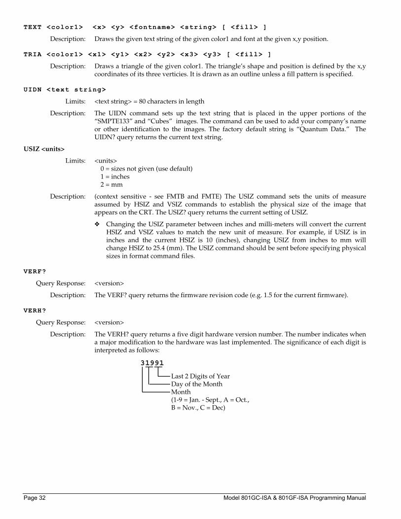
Description: The VERH? query returns a five digit hardware version number. The number indicates when a major modification to the hardware was last implemented. The significance of each digit is interpreted as follows:
Last 2 Digits of YearDay of the MonthMonth(1-9 = Jan. - Sept., A = Oct.,B = Nov., C = Dec)
31991
Publication # 68-00155 (Rev: B 26-JULY-95) Page 33
VRES <lines>
Limits: <lines> min = 1 (when SCAN = 1) or 2 (when SCAN = 2) max = the lesser of 1024 or VTOT-1 (when SCAN = 1) or VTOT-3 (when SCAN = 2) Must be an even number when SCAN = 2.
Description: The VRES command establishes the number of active lines per frame. The VRES? query returns the current setting of VRES.
VSIZ <physical size>
Limits: <physical size> = positive value (floating point accepted)
Description: (context sensitive - see FMTB and FMTE) The VSIZ command establishes the vertical physical size of the image on the display. Units expected (or returned) vary according to the last mode set with USIZ command. The VSIZ command is context sensitive and must appear between begin and end commands: FMTB and FMTE. The VSIZ? query returns the current setting of VSIZ.
❖ Make sure that the USIZ parameter is properly set before using the VSIZ command. Changing the USIZ setting after entering VSIZ will convert the size to match the new unit of measure.
VSPD <lines>
Limits: <lines> min = 0 (when SCAN = 1) or 1 (when SCAN = 2) max = VTOT-VRES-VSPW (when SCAN = 1) or [(VTOT-VRES-1) /2]-VSPW (when SCAN = 2)
Description: The VSPD command establishes the delay between leading edge of blanking in the first (or even) field and the leading edge of the vertical sync pulse. When interlacing, delay between end of video and leading edge of vertical sync before second (or odd) field is 0.5 line shorter than the whole-line delay specified. The VSPD? query returns the current setting of the vertical sync pulse delay.
VSPG <mode>
Limits: <mode> 0 = OFF 1 = ON
Description: The VSPG command enables and disables all of the digital vertical sync outputs. If digital composite sync is selected (see SSST command) and VSPG=1, then composite sync is output on both the VS-BNC and the VS pin of the VGA D-sub connector in addition to the CS pins of the MAC & PGA D-sub connectors. The VSPG? query returns the current mode of VSPG.
VSPP <polarity>
Limits: <polarity> 0 = active-low (negative going pulse) 1 = active-high (positive going pulse)
Description: The VSPP command establishes the logic sense of the digital vertical sync outputs. Setting polarity to 1 causes the leading edge of vertical sync to be a low-to-high transition. Setting polarity to 0 causes the leading edge of vertical sync to be a high-to-low transition. The VSPP? query returns the current polarity of VSPP.
Page 34 Model 801GC-ISA & 801GF-ISA Programming Manual
VSPW <lines>
Limits: <lines> =
Description: The VSPW command establish the width of the vertical sync pulse in lines. If the type specified for the selected sync signal (see SSST, ASCT, DSCT, or DSST commands) is one of the CCIR types, then the actual sync pulse width output by the generator will be 1/2 line shorter than the whole number specified. The VSPW? query returns the current setting of VSPW.
VTOT <lines>
Limits: <lines> min = 2 max = 65535 Must be an odd number when SCAN = 2
Description: The VTOT command establishes the total number of lines per frame. When interlacing (SCAN=2), VTOT must be odd. The VTOT? query returns the current setting of VTOT.
The frame or picture refresh rate is equal to the quotient of: HRAT divided by VTOT.
The field or vertical rate is equal to the frame rate when SCAN = 1 (non-interlaced operation).
The field or vertical rate is equal to twice the frame rate when SCAN = 2 (non-interlaced operation).
❖ The current version of the firmware does not allow you to directly enter a specific field or frame rate when setting up a format. If your test specifications call for a specific field, frame or vertical refresh rate, enter suitable values for HRAT, SCAN and VTOT to give you the desired rate.
XVSG <red mode>, <green mode>, <blue mode>
Limits: <all modes> 0 = OFF 1 = ON
Description: The XVSG command determines which video outputs will be active when the format is selected. The same command controls both the analog and digital video outputs.
Publication # 68-00155 (Rev: B 26-JULY-95) Page 35
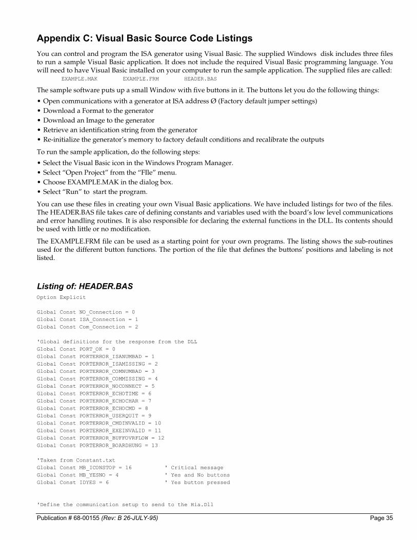
Appendix C: Visual Basic Source Code Listings You can control and program the ISA generator using Visual Basic. The supplied Windows disk includes three files to run a sample Visual Basic application. It does not include the required Visual Basic programming language. You will need to have Visual Basic installed on your computer to run the sample application. The supplied files are called: EXAMPLE.MAK EXAMPLE.FRM HEADER.BAS
The sample software puts up a small Window with five buttons in it. The buttons let you do the following things:
• Open communications with a generator at ISA address Ø (Factory default jumper settings) • Download a Format to the generator • Download an Image to the generator • Retrieve an identification string from the generator • Re-initialize the generator’s memory to factory default conditions and recalibrate the outputs
To run the sample application, do the following steps:
• Select the Visual Basic icon in the Windows Program Manager. • Select “Open Project” from the “FIle” menu. • Choose EXAMPLE.MAK in the dialog box. • Select “Run” to start the program.
You can use these files in creating your own Visual Basic applications. We have included listings for two of the files. The HEADER.BAS file takes care of defining constants and variables used with the board’s low level communications and error handling routines. It is also responsible for declaring the external functions in the DLL. Its contents should be used with little or no modification.
The EXAMPLE.FRM file can be used as a starting point for your own programs. The listing shows the sub-routines used for the different button functions. The portion of the file that defines the buttons’ positions and labeling is not listed.
Listing of: HEADER.BAS Option Explicit Global Const NO_Connection = 0 Global Const ISA_Connection = 1 Global Const Com_Connection = 2 'Global definitions for the response from the DLL Global Const PORT_OK = 0 Global Const PORTERROR_ISANUMBAD = 1 Global Const PORTERROR_ISAMISSING = 2 Global Const PORTERROR_COMNUMBAD = 3 Global Const PORTERROR_COMMISSING = 4 Global Const PORTERROR_NOCONNECT = 5 Global Const PORTERROR_ECHOTIME = 6 Global Const PORTERROR_ECHOCHAR = 7 Global Const PORTERROR_ECHOCMD = 8 Global Const PORTERROR_USERQUIT = 9 Global Const PORTERROR_CMDINVALID = 10 Global Const PORTERROR_EXEINVALID = 11 Global Const PORTERROR_BUFFOVRFLOW = 12 Global Const PORTERROR_BOARDHUNG = 13 'Taken from Constant.txt Global Const MB_ICONSTOP = 16 ' Critical message Global Const MB_YESNO = 4 ' Yes and No buttons Global Const IDYES = 6 ' Yes button pressed 'Define the communication setup to send to the Hia.Dll
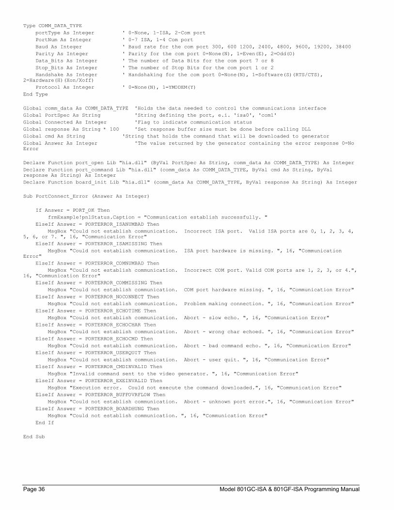
Page 36 Model 801GC-ISA & 801GF-ISA Programming Manual
Type COMM_DATA_TYPE portType As Integer ' 0-None, 1-ISA, 2-Com port PortNum As Integer ' 0-7 ISA, 1-4 Com port Baud As Integer ' Baud rate for the com port 300, 600 1200, 2400, 4800, 9600, 19200, 38400 Parity As Integer ' Parity for the com port 0=None(N), 1=Even(E), 2=Odd(O) Data_Bits As Integer ' The number of Data Bits for the com port 7 or 8 Stop_Bits As Integer ' The number of Stop Bits for the com port 1 or 2 Handshake As Integer ' Handshaking for the com port 0=None(N), 1=Software(S)(RTS/CTS), 2=Hardware(H)(Xon/Xoff) Protocol As Integer ' 0=None(N), 1=YMODEM(Y) End Type Global comm_data As COMM_DATA_TYPE 'Holds the data needed to control the communications interface Global PortSpec As String 'String defining the port, e.i. 'isa0', 'com1' Global Connected As Integer 'Flag to indicate communication status Global response As String * 100 'Set response buffer size must be done before calling DLL Global cmd As String 'String that holds the command that will be downloaded to generator Global Answer As Integer 'The value returned by the generator containing the error response 0=No Error Declare Function port_open Lib "hia.dll" (ByVal PortSpec As String, comm_data As COMM_DATA_TYPE) As Integer Declare Function port_command Lib "hia.dll" (comm_data As COMM_DATA_TYPE, ByVal cmd As String, ByVal response As String) As Integer Declare Function board_init Lib "hia.dll" (comm_data As COMM_DATA_TYPE, ByVal response As String) As Integer Sub PortConnect_Error (Answer As Integer) If Answer = PORT_OK Then frmExample!pnlStatus.Caption = "Communication establish successfully. " ElseIf Answer = PORTERROR_ISANUMBAD Then MsgBox "Could not establish communication. Incorrect ISA port. Valid ISA ports are 0, 1, 2, 3, 4, 5, 6, or 7. ", 16, "Communication Error" ElseIf Answer = PORTERROR_ISAMISSING Then MsgBox "Could not establish communication. ISA port hardware is missing. ", 16, "Communication Error" ElseIf Answer = PORTERROR_COMNUMBAD Then MsgBox "Could not establish communication. Incorrect COM port. Valid COM ports are 1, 2, 3, or 4.", 16, "Communication Error" ElseIf Answer = PORTERROR_COMMISSING Then MsgBox "Could not establish communication. COM port hardware missing. ", 16, "Communication Error" ElseIf Answer = PORTERROR_NOCONNECT Then MsgBox "Could not establish communication. Problem making connection. ", 16, "Communication Error" ElseIf Answer = PORTERROR_ECHOTIME Then MsgBox "Could not establish communication. Abort - slow echo. ", 16, "Communication Error" ElseIf Answer = PORTERROR_ECHOCHAR Then MsgBox "Could not establish communication. Abort - wrong char echoed. ", 16, "Communication Error" ElseIf Answer = PORTERROR_ECHOCMD Then MsgBox "Could not establish communication. Abort - bad command echo. ", 16, "Communication Error" ElseIf Answer = PORTERROR_USERQUIT Then MsgBox "Could not establish communication. Abort - user quit. ", 16, "Communication Error" ElseIf Answer = PORTERROR_CMDINVALID Then MsgBox "Invalid command sent to the video generator. ", 16, "Communication Error" ElseIf Answer = PORTERROR_EXEINVALID Then MsgBox "Execution error. Could not execute the command downloaded.", 16, "Communication Error" ElseIf Answer = PORTERROR_BUFFOVRFLOW Then MsgBox "Could not establish communication. Abort - unknown port error.", 16, "Communication Error" ElseIf Answer = PORTERROR_BOARDHUNG Then MsgBox "Could not establish communication. ", 16, "Communication Error" End If End Sub
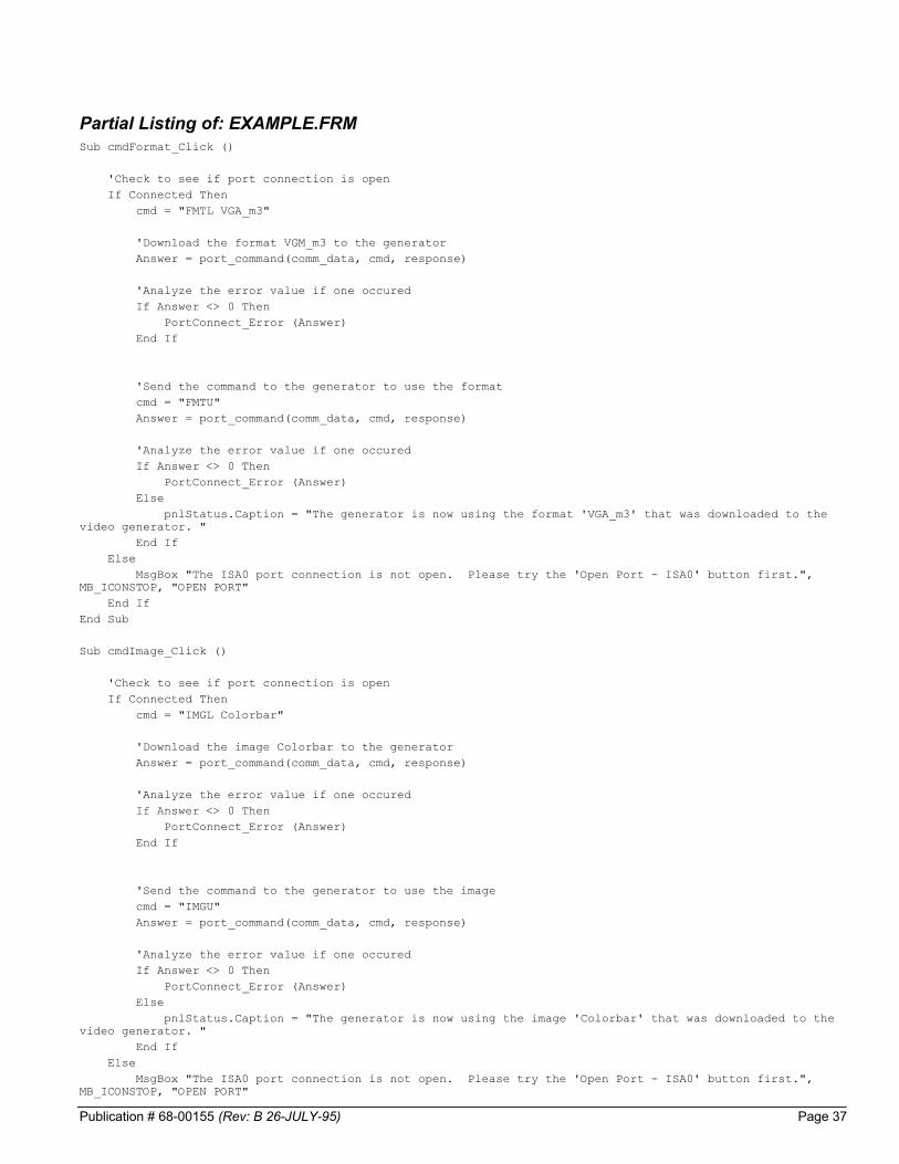
Publication # 68-00155 (Rev: B 26-JULY-95) Page 37
Partial Listing of: EXAMPLE.FRM Sub cmdFormat_Click () 'Check to see if port connection is open If Connected Then cmd = "FMTL VGA_m3" 'Download the format VGM_m3 to the generator Answer = port_command(comm_data, cmd, response) 'Analyze the error value if one occured If Answer <> 0 Then PortConnect_Error (Answer) End If 'Send the command to the generator to use the format cmd = "FMTU" Answer = port_command(comm_data, cmd, response) 'Analyze the error value if one occured If Answer <> 0 Then PortConnect_Error (Answer) Else pnlStatus.Caption = "The generator is now using the format 'VGA_m3' that was downloaded to the video generator. " End If Else MsgBox "The ISA0 port connection is not open. Please try the 'Open Port - ISA0' button first.", MB_ICONSTOP, "OPEN PORT" End If End Sub Sub cmdImage_Click () 'Check to see if port connection is open If Connected Then cmd = "IMGL Colorbar" 'Download the image Colorbar to the generator Answer = port_command(comm_data, cmd, response) 'Analyze the error value if one occured If Answer <> 0 Then PortConnect_Error (Answer) End If 'Send the command to the generator to use the image cmd = "IMGU" Answer = port_command(comm_data, cmd, response) 'Analyze the error value if one occured If Answer <> 0 Then PortConnect_Error (Answer) Else pnlStatus.Caption = "The generator is now using the image 'Colorbar' that was downloaded to the video generator. " End If Else MsgBox "The ISA0 port connection is not open. Please try the 'Open Port - ISA0' button first.", MB_ICONSTOP, "OPEN PORT"
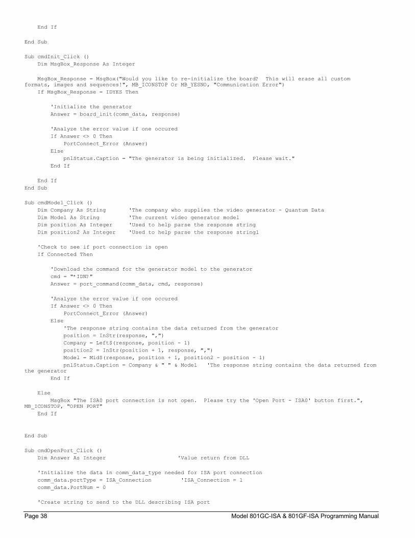
Page 38 Model 801GC-ISA & 801GF-ISA Programming Manual
End If End Sub Sub cmdInit_Click () Dim MsgBox_Response As Integer MsgBox_Response = MsgBox("Would you like to re-initialize the board? This will erase all custom formats, images and sequences!", MB_ICONSTOP Or MB_YESNO, "Communication Error") If MsgBox_Response = IDYES Then 'Initialize the generator Answer = board_init(comm_data, response) 'Analyze the error value if one occured If Answer <> 0 Then PortConnect_Error (Answer) Else pnlStatus.Caption = "The generator is being initialized. Please wait." End If End If End Sub Sub cmdModel_Click () Dim Company As String 'The company who supplies the video generator - Quantum Data Dim Model As String 'The current video generator model Dim position As Integer 'Used to help parse the response string Dim position2 As Integer 'Used to help parse the response stringl 'Check to see if port connection is open If Connected Then 'Download the command for the generator model to the generator cmd = "*IDN?" Answer = port_command(comm_data, cmd, response) 'Analyze the error value if one occured If Answer <> 0 Then PortConnect_Error (Answer) Else 'The response string contains the data returned from the generator position = InStr(response, ",") Company = Left$(response, position - 1) position2 = InStr(position + 1, response, ",") Model = Mid$(response, position + 1, position2 - position - 1) pnlStatus.Caption = Company & " " & Model 'The response string contains the data returned from the generator End If Else MsgBox "The ISA0 port connection is not open. Please try the 'Open Port - ISA0' button first.", MB_ICONSTOP, "OPEN PORT" End If End Sub Sub cmdOpenPort_Click () Dim Answer As Integer 'Value return from DLL 'Initialize the data in comm_data_type needed for ISA port connection comm_data.portType = ISA_Connection 'ISA_Connection = 1 comm_data.PortNum = 0 'Create string to send to the DLL describing ISA port

Publication # 68-00155 (Rev: B 26-JULY-95) Page 39
PortSpec = "ISA" & comm_data.PortNum 'Access the DLL routine to open the port Answer = port_open(PortSpec, comm_data) PortConnect_Error (Answer) If Answer = PORT_OK Then Connected = True Else Connected = False End If End Sub

Page 40 Model 801GC-ISA & 801GF-ISA Programming Manual
®
Quantum Data Corporation 2111 Big Timber Road Elgin, IL 60123 USA Phone: (847) 888-0450 www.quantumdata.com/