Embed Size (px)
Citation preview
Pub. 42004-453C
GAI-TRONICS 3030 KUTZTOWN RD. READING, PA 19605 USA 610-777-1374 800-492-1212 Fax: 610-796-5954
VISIT WWW.GAI-TRONICS.COM FOR PRODUCT LITERATURE AND MANUALS
G A I - T R O N I C S ® A H U B B E L L C O M P A N Y
Model DHS/DHF 200 Series Digital Intercom Stations
T A B L E O F C O N T E N T S
Confidentiality Notice .....................................................................................................................1
General Information .......................................................................................................................1
Product Overview ................................................................................................................................... 1
System Requirements and Limitations ................................................................................................. 1
Features and Functions .......................................................................................................................... 2
Model Chart ............................................................................................................................................ 2
Available Models ..................................................................................................................................... 3 Wall-Mount Handset Intercoms (Indoor/Outdoor) ............................................................................................... 3 Wall-Mount Hands-free Intercoms (Indoor/Outdoor) ........................................................................................... 3 Flush-Mount Hands-free Intercoms ...................................................................................................................... 3
Description of Major Components ........................................................................................................ 4
Installation ......................................................................................................................................5
General Information ............................................................................................................................... 5
General Installation Guidelines ............................................................................................................. 5
Security Hardware .................................................................................................................................. 5
Conduit Installation Details ................................................................................................................... 6
Mounting .................................................................................................................................................. 7 Models DHS-201, DHF-201, and DHF-202 ......................................................................................................... 7 Models DHF-203 and DHF-204 ........................................................................................................................... 8
Field Wire Installation .......................................................................................................................... 10 Power .................................................................................................................................................................. 10 System ................................................................................................................................................................. 12 Audio .................................................................................................................................................................. 12 Audio Level Adjustments ................................................................................................................................... 13 Switch Configuration .......................................................................................................................................... 16 Inputs .................................................................................................................................................................. 17 Outputs ................................................................................................................................................................ 17
Operation .......................................................................................................................................19
Hands-free Operation ........................................................................................................................... 19
Handset Operation ................................................................................................................................ 19
Headset Operation ................................................................................................................................ 20
Paging ..................................................................................................................................................... 20
Table of Contents Pub. 42004-453C MODEL DHS/DHF 200 SERIES DIGITAL INTERCOM STATIONS
GAI-TRONICS 3030 KUTZTOWN RD. READING, PA 19605 USA 610-777-1374 800-492-1212 Fax: 610-796-5954
VISIT WWW.GAI-TRONICS.COM FOR Pii RODUCT LITERATURE AND MANUALS
Alarms and Music ................................................................................................................................. 20
Status Indication ................................................................................................................................... 21 Call Status ........................................................................................................................................................... 21
Controls .................................................................................................................................................. 21 Keypad ................................................................................................................................................................ 21 Single Button Dialing ......................................................................................................................................... 21 Talk/Listen Control ............................................................................................................................................. 21 Call Cancel .......................................................................................................................................................... 21 Master Volume ................................................................................................................................................... 21
Maintenance ..................................................................................................................................22
General Information ............................................................................................................................. 22
Troubleshooting .................................................................................................................................... 22 Service ................................................................................................................................................................ 23
Replacement Parts ................................................................................................................................ 23
Specifications ................................................................................................................................24
Pub. 42004-453C
GAI-TRONICS 3030 KUTZTOWN RD. READING, PA 19605 USA 610-777-1374 800-492-1212 Fax: 610-796-5954
VISIT WWW.GAI-TRONICS.COM FOR PRODUCT LITERATURE AND MANUALS
G A I - T R O N I C S ® A H U B B E L L C O M P A N Y
Model DHS/DHF 200 Series Digital Intercom Stations
Confidentiality Notice This manual is provided solely as an operational, installation, and maintenance guide and contains sensitive business and technical information that is confidential and proprietary to GAI-Tronics. GAI-Tronics retains all intellectual property and other rights in or to the information contained herein, and such information may only be used in connection with the operation of your GAI-Tronics product or system. This manual may not be disclosed in any form, in whole or in part, directly or indirectly, to any third party.
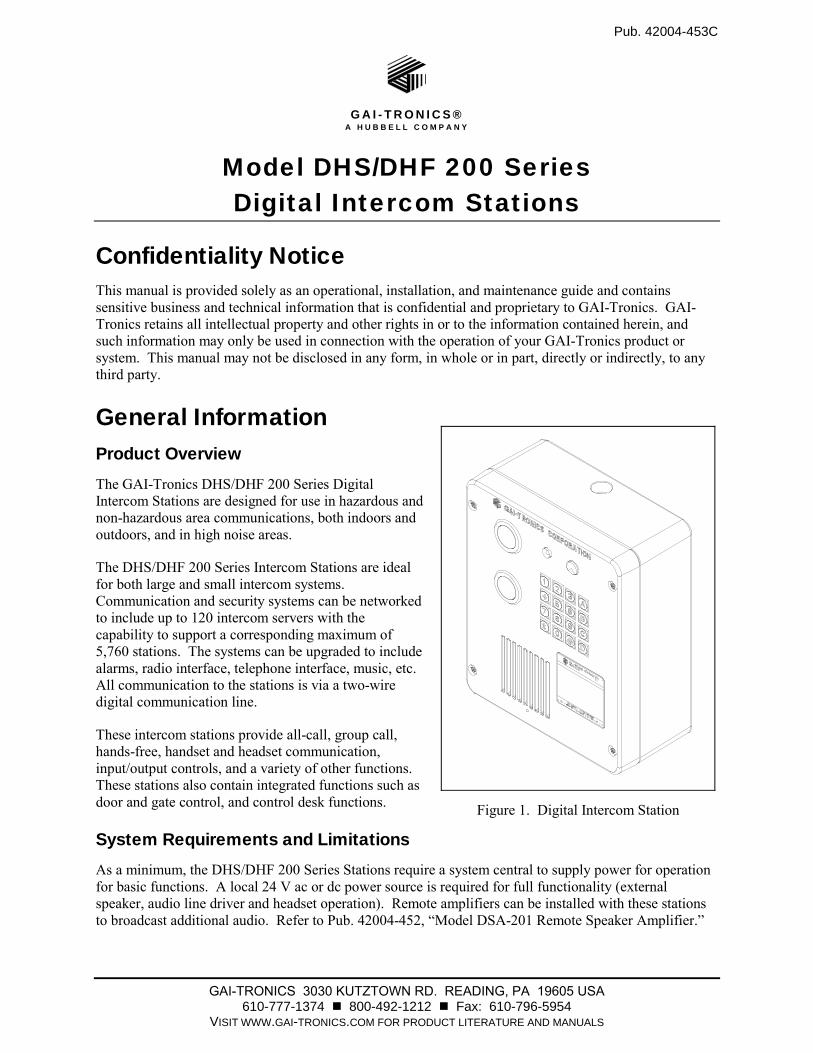
General Information Product Overview The GAI-Tronics DHS/DHF 200 Series Digital Intercom Stations are designed for use in hazardous and non-hazardous area communications, both indoors and outdoors, and in high noise areas.
The DHS/DHF 200 Series Intercom Stations are ideal for both large and small intercom systems. Communication and security systems can be networked to include up to 120 intercom servers with the capability to support a corresponding maximum of 5,760 stations. The systems can be upgraded to include alarms, radio interface, telephone interface, music, etc. All communication to the stations is via a two-wire digital communication line.
These intercom stations provide all-call, group call, hands-free, handset and headset communication, input/output controls, and a variety of other functions. These stations also contain integrated functions such as door and gate control, and control desk functions.
System Requirements and Limitations As a minimum, the DHS/DHF 200 Series Stations require a system central to supply power for operation for basic functions. A local 24 V ac or dc power source is required for full functionality (external speaker, audio line driver and headset operation). Remote amplifiers can be installed with these stations to broadcast additional audio. Refer to Pub. 42004-452, “Model DSA-201 Remote Speaker Amplifier.”
Figure 1. Digital Intercom Station
Pub. 42004-453C MODEL DHS/DHF 200 SERIES DIGITAL INTERCOM STATIONS Page 2 of 25
f:\standard ioms - current release\42004 instr. manuals\42004-453c.doc 10/12
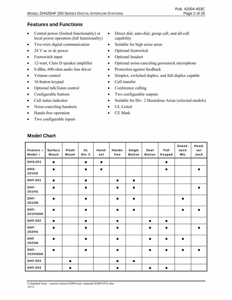
Features and Functions
Central power (limited functionality) orlocal power operation (full functionality)
Direct dial, auto-dial, group call, and all-callcapability
Two-wire digital communication Suitable for high noise areas
24 V ac or dc power Optional footswitch
Footswitch input Optional headset
12-watt, Class D speaker amplifier Optional noise-canceling gooseneck microphone
0 dBm, 600-ohm audio line driver Protection against feedback
Volume control Simplex, switched duplex, and full-duplex capable
16-button keypad Call transfer
Optional talk/listen control Conference calling
Configurable buttons Two configurable outputs
Call status indicator Suitable for Div. 2 Hazardous Areas (selected models)
Noise-canceling handsets UL Listed
Hands-free operation CE Mark
Two configurable inputs
Model Chart
Feature Model
Surface Mount
Flush Mount
UL Div. 2
Hand- set
Hands- free
Single Button
Dual Button
Full Keypad
Goose- neck Mic
Head- set
Jack
DHS-201
DHS-201HS
DHF-201
DHF- 201HS
DHF-201GN
DHF-201HSGN
DHF-202
DHF-202HS
DHF 202GN
DHF-202HSGN
DHF-203
DHF-204
Pub. 42004-453C MODEL DHS/DHF 200 SERIES DIGITAL INTERCOM STATIONS Page 3 of 25
f:\standard ioms - current release\42004 instr. manuals\42004-453c.doc 10/12
Available Models
Wall-Mount Handset Intercoms (Indoor/Outdoor)
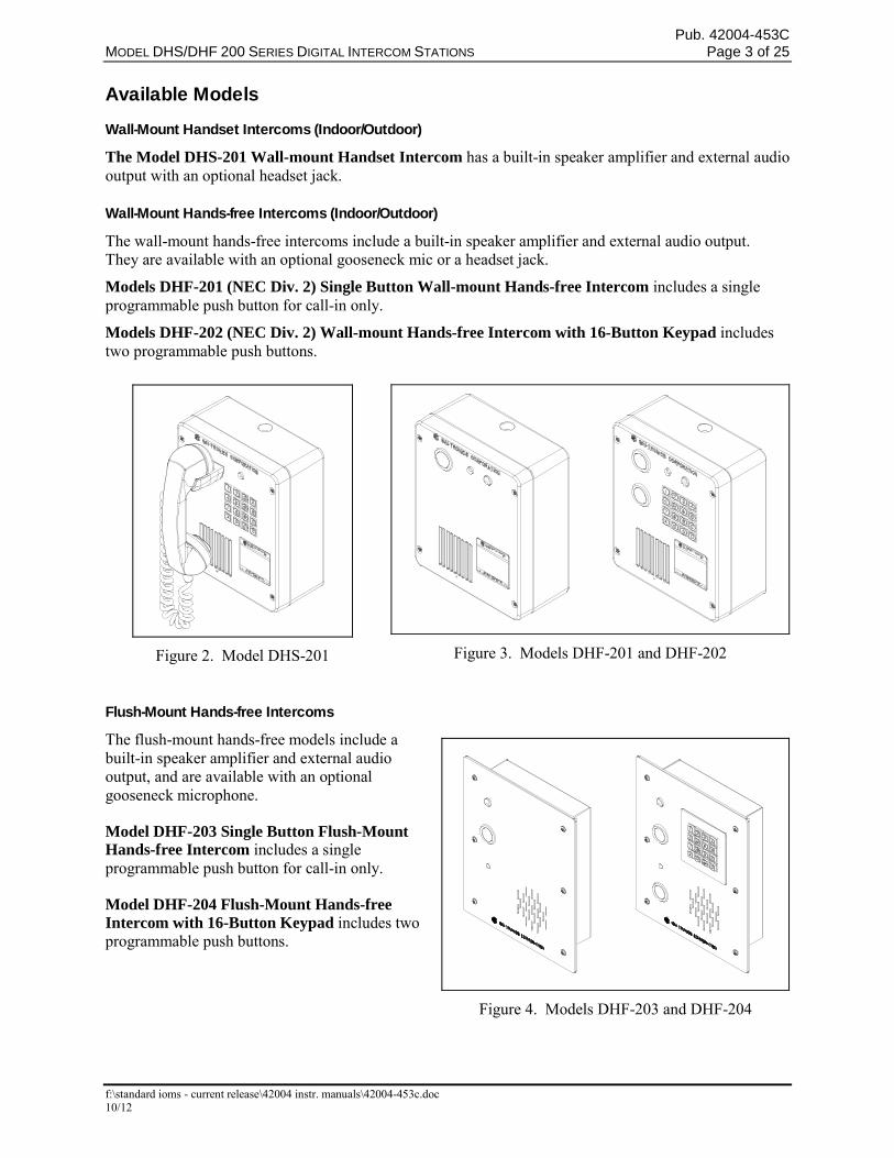
The Model DHS-201 Wall-mount Handset Intercom has a built-in speaker amplifier and external audio output with an optional headset jack.
Wall-Mount Hands-free Intercoms (Indoor/Outdoor)
The wall-mount hands-free intercoms include a built-in speaker amplifier and external audio output. They are available with an optional gooseneck mic or a headset jack.
Models DHF-201 (NEC Div. 2) Single Button Wall-mount Hands-free Intercom includes a single programmable push button for call-in only.
Models DHF-202 (NEC Div. 2) Wall-mount Hands-free Intercom with 16-Button Keypad includes two programmable push buttons.
Flush-Mount Hands-free Intercoms
The flush-mount hands-free models include a built-in speaker amplifier and external audio output, and are available with an optional gooseneck microphone.
Model DHF-203 Single Button Flush-Mount Hands-free Intercom includes a single programmable push button for call-in only.
Model DHF-204 Flush-Mount Hands-free Intercom with 16-Button Keypad includes two programmable push buttons.
Figure 2. Model DHS-201 Figure 3. Models DHF-201 and DHF-202
Figure 4. Models DHF-203 and DHF-204
Pub. 42004-453C MODEL DHS/DHF 200 SERIES DIGITAL INTERCOM STATIONS Page 4 of 25
f:\standard ioms - current release\42004 instr. manuals\42004-453c.doc 10/12
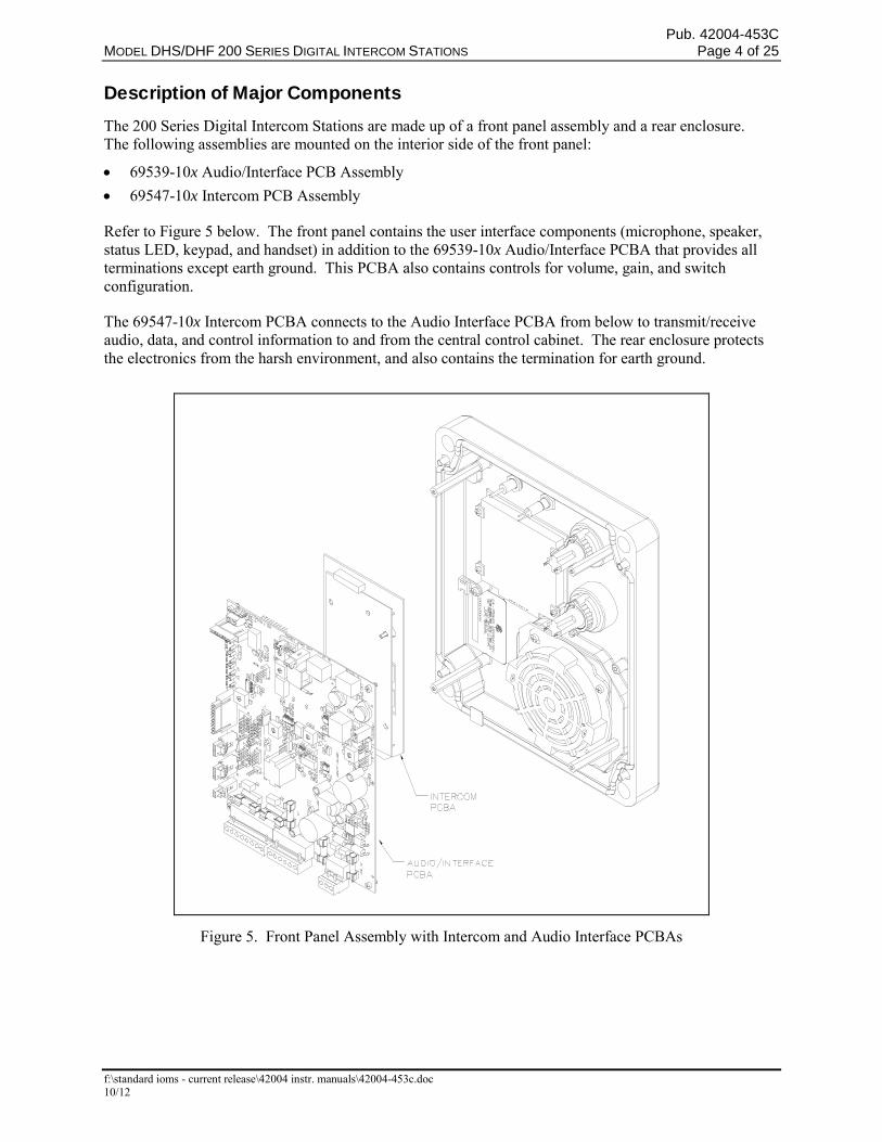
Description of Major Components The 200 Series Digital Intercom Stations are made up of a front panel assembly and a rear enclosure. The following assemblies are mounted on the interior side of the front panel:
69539-10x Audio/Interface PCB Assembly
69547-10x Intercom PCB Assembly
Refer to Figure 5 below. The front panel contains the user interface components (microphone, speaker, status LED, keypad, and handset) in addition to the 69539-10x Audio/Interface PCBA that provides all terminations except earth ground. This PCBA also contains controls for volume, gain, and switch configuration.
The 69547-10x Intercom PCBA connects to the Audio Interface PCBA from below to transmit/receive audio, data, and control information to and from the central control cabinet. The rear enclosure protects the electronics from the harsh environment, and also contains the termination for earth ground.
Figure 5. Front Panel Assembly with Intercom and Audio Interface PCBAs
Pub. 42004-453C MODEL DHS/DHF 200 SERIES DIGITAL INTERCOM STATIONS Page 5 of 25
f:\standard ioms - current release\42004 instr. manuals\42004-453c.doc 10/12
Installation General Information
WARNING This equipment is suitable for use in Class I, Division 2, Groups A, B, C and D, Class II Division 2, Groups F, and G, Class III OR non-hazardous locations only. Combinations of equipment in your system are subject to investigation by the local Authority Having Jurisdiction at the time of installation.
WARNING EXPLOSION HAZARD – Do not disconnect equipment unless power has been removed or the area is known to be non-hazardous.
WARNING EXPLOSION HAZARD - Substitution of components may impair suitability for Class I, Division 2.
Averttissement – Risque d’explosion - la substitition de composants peut rendre ce matériel inacceptable pour les em-placements de Classe 1, Division 2.
Averttissement – Risque d’explosion – avant de déconnector l’equipment, couper le courant ou s’assurer que l’emplacement est désigné non dandereux.
Install equipment without modification and according to all applicable local and national electrical codes.
USA and Canada Consult the National Electrical Code (NFPA 70), Canadian Standards Association (CSA 22.1), and local codes for specific requirements regarding your installation. Class 2 circuit wiring must be performed in accordance with NEC 725.55.
General Installation Guidelines This station contains a high gain amplifier, which enables operation in high noise environments. To prevent feedback problems in the system, the ambient noise levels, volume settings, and station placement must be taken into consideration. Unpleasant feedback problems can be reduced by taking the following measures:
Pointing the speaker away from nearby Intercom Stations
Placing the speakers in separate rooms from Intercom Stations
Reducing volume levels
Security Hardware The stations in the manual are vandal resistant. The front panel is attached to its enclosure with security screws. A GAI-Tronics Model 233-001 Security Screwdriver or Torx T-25 security head tip (sold separately) is required for installing or removing the front panel.
Pub. 42004-453C MODEL DHS/DHF 200 SERIES DIGITAL INTERCOM STATIONS Page 6 of 25
f:\standard ioms - current release\42004 instr. manuals\42004-453c.doc 10/12
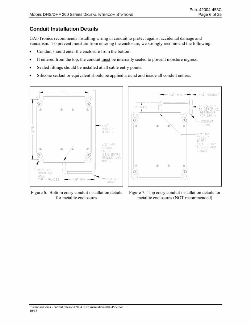
Conduit Installation Details GAI-Tronics recommends installing wiring in conduit to protect against accidental damage and vandalism. To prevent moisture from entering the enclosure, we strongly recommend the following:
Conduit should enter the enclosure from the bottom.
If entered from the top, the conduit must be internally sealed to prevent moisture ingress.
Sealed fittings should be installed at all cable entry points.
Silicone sealant or equivalent should be applied around and inside all conduit entries.
Figure 6. Bottom entry conduit installation details for metallic enclosures
Figure 7. Top entry conduit installation details for metallic enclosures (NOT recommended)
Pub. 42004-453C MODEL DHS/DHF 200 SERIES DIGITAL INTERCOM STATIONS Page 7 of 25
f:\standard ioms - current release\42004 instr. manuals\42004-453c.doc 10/12
Mounting
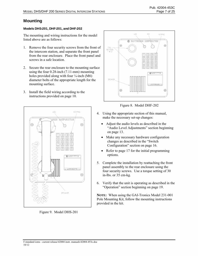
Models DHS-201, DHF-201, and DHF-202
The mounting and wiring instructions for the model listed above are as follows:
1. Remove the four security screws from the front of the intercom station, and separate the front panel from the rear enclosure. Place the front panel and screws in a safe location.
2. Secure the rear enclosure to the mounting surface using the four 0.28-inch (7.11-mm) mounting holes provided along with four ¼-inch (M6) diameter bolts of the appropriate length for the mounting surface.
3. Install the field wiring according to the instructions provided on page 10.
4. Using the appropriate section of this manual, make the necessary set-up changes:
Adjust the audio levels as described in the “Audio Level Adjustments” section beginning on page 13.
Make any necessary hardware configuration changes as described in the “Switch Configuration” section on page 16.
Refer to page 17 for the initial programming options.
5. Complete the installation by reattaching the front panel assembly to the rear enclosure using the four security screws. Use a torque setting of 30 in-lbs. or 35 cm-kg.
6. Verify that the unit is operating as described in the “Operation” section beginning on page 19.
NOTE: When using the GAI-Tronics Model 231-001 Pole Mounting Kit, follow the mounting instructions provided in the kit.
Figure 8. Model DHF-202
Figure 9. Model DHS-201
Pub. 42004-453C MODEL DHS/DHF 200 SERIES DIGITAL INTERCOM STATIONS Page 8 of 25
f:\standard ioms - current release\42004 instr. manuals\42004-453c.doc 10/12
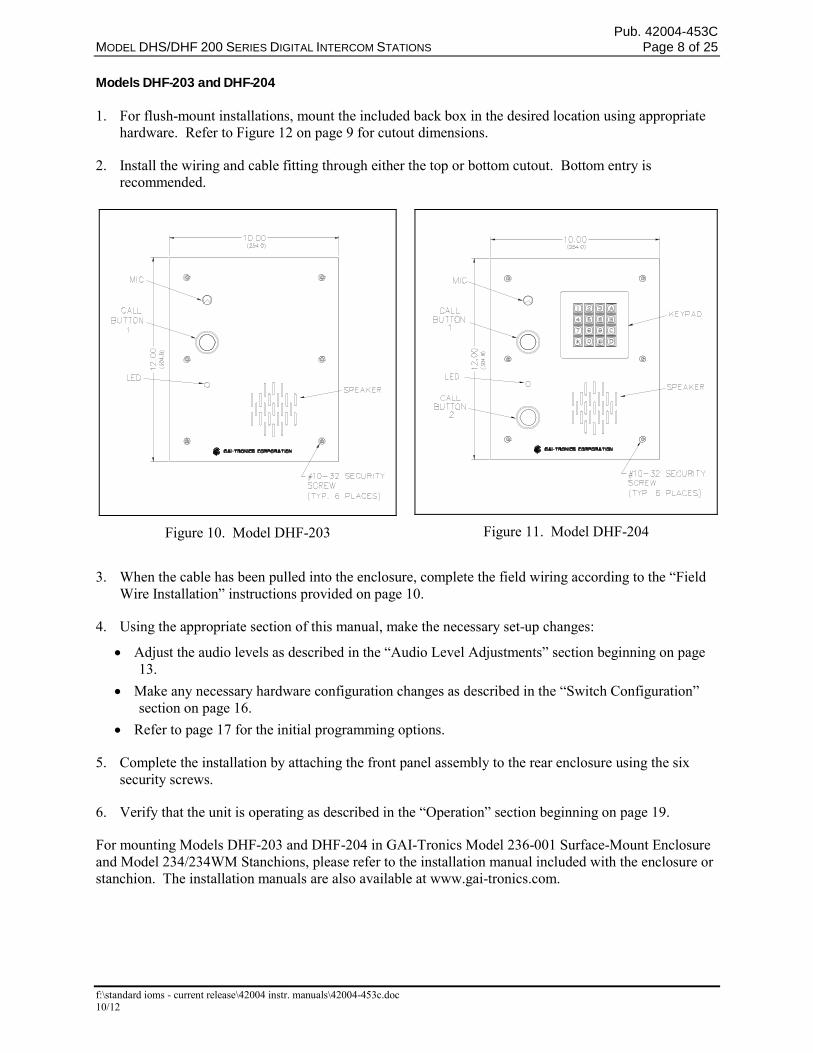
Models DHF-203 and DHF-204
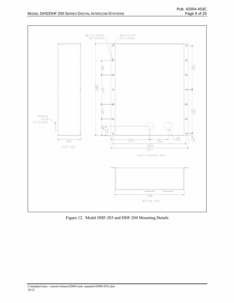
1. For flush-mount installations, mount the included back box in the desired location using appropriate hardware. Refer to Figure 12 on page 9 for cutout dimensions.
2. Install the wiring and cable fitting through either the top or bottom cutout. Bottom entry is recommended.
Figure 10. Model DHF-203
Figure 11. Model DHF-204
3. When the cable has been pulled into the enclosure, complete the field wiring according to the “Field
Wire Installation” instructions provided on page 10.
4. Using the appropriate section of this manual, make the necessary set-up changes:
Adjust the audio levels as described in the “Audio Level Adjustments” section beginning on page 13.
Make any necessary hardware configuration changes as described in the “Switch Configuration” section on page 16.
Refer to page 17 for the initial programming options.
5. Complete the installation by attaching the front panel assembly to the rear enclosure using the six security screws.
6. Verify that the unit is operating as described in the “Operation” section beginning on page 19.
For mounting Models DHF-203 and DHF-204 in GAI-Tronics Model 236-001 Surface-Mount Enclosure and Model 234/234WM Stanchions, please refer to the installation manual included with the enclosure or stanchion. The installation manuals are also available at www.gai-tronics.com.
Pub. 42004-453C MODEL DHS/DHF 200 SERIES DIGITAL INTERCOM STATIONS Page 9 of 25
f:\standard ioms - current release\42004 instr. manuals\42004-453c.doc 10/12
Figure 12. Model DHF-203 and DHF-204 Mounting Details
Pub. 42004-453C MODEL DHS/DHF 200 SERIES DIGITAL INTERCOM STATIONS Page 10 of 25
f:\standard ioms - current release\42004 instr. manuals\42004-453c.doc 10/12
Field Wire Installation
1. Unfasten the front panel assembly.
2. Pull the field wiring through the conduit entrance in the rear of the enclosure . The use of ferrules is recommended on the ends of stranded wire to create a secure, reliable connection.
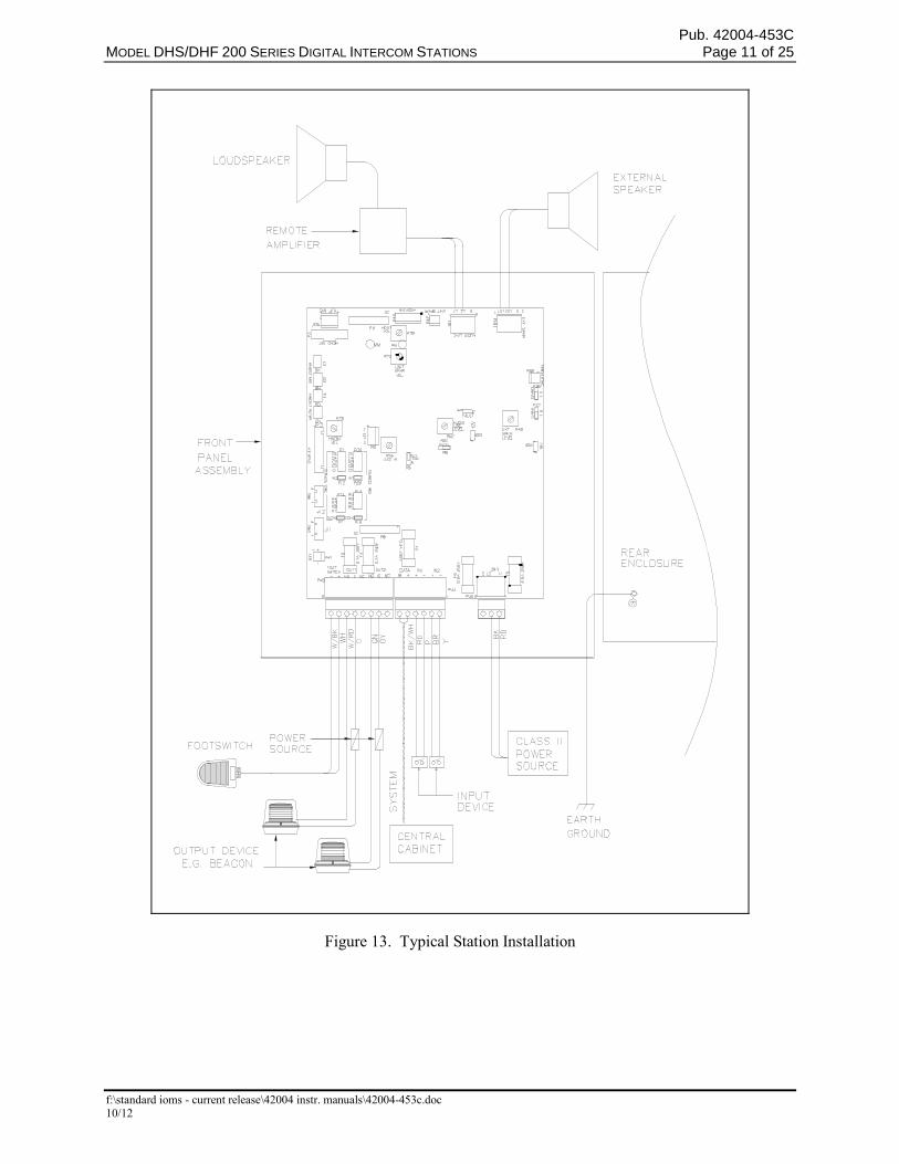
3. Install all connections as indicated below. Refer to Figure 13 for wiring details. Refer to Table 1 and Table 2 on page 12 for the recommended conductor sizes and lengths.
NOTE: USA and Canada - Consult the National Electrical Code (NFPA 70), Canadian Standards Association (CSA 22.1), and local codes for the specific requirements regarding your installation. Install all equipment without modification and according to the local and national codes. Class 2 circuit wiring must be performed in accordance with NEC 725.55.
Power
Central Power
This assembly is capable of operating without a 24 V ac or dc power source. When a 24 V dc power source is not connected to P46, this station is powered by the central cabinet via the system cable. This will limit the functionality of this station and limit the distance from the central cabinet. The following functions will not be operational when central power is used:
External speaker amplifier
Audio line driver
Headset operation
Configurable outputs
The enclosure must be connected to earth ground. Install a ring lug on the ground conductor prior to connection to the enclosure. Secure the ring lug to the #6 ground screw on the rear enclosure.
Local Power
This assembly requires a 24 V ac or dc power source for the station to be fully functional. The following functions are enabled when central power is used:
External speaker amplifier
Audio line driver
Headset operation
Configurable outputs
A separate power feed is recommended for each intercom station. A pluggable terminal block P46 is provided for connection of power to the station. Power leads can be connected to either L1 or L2 in ac or dc systems. Also, the enclosure must be connected to earth ground. Install a ring lug on the ground conductor prior to connection to the enclosure. Secure the ring lug to the #6 ground screw on the rear enclosure.
Installation of this equipment shall be carried out by suitably-trained personnel in accordance with the applicable code of practice concerning equipment and protective systems intended for use in potentially Explosive Atmospheres.
Pub. 42004-453C MODEL DHS/DHF 200 SERIES DIGITAL INTERCOM STATIONS Page 11 of 25
f:\standard ioms - current release\42004 instr. manuals\42004-453c.doc 10/12
Figure 13. Typical Station Installation
Pub. 42004-453C MODEL DHS/DHF 200 SERIES DIGITAL INTERCOM STATIONS Page 12 of 25
f:\standard ioms - current release\42004 instr. manuals\42004-453c.doc 10/12
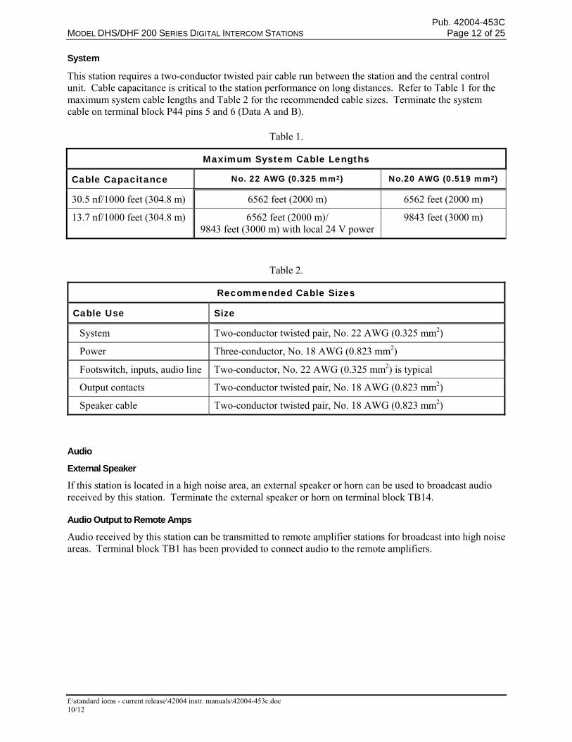
System
This station requires a two-conductor twisted pair cable run between the station and the central control unit. Cable capacitance is critical to the station performance on long distances. Refer to Table 1 for the maximum system cable lengths and Table 2 for the recommended cable sizes. Terminate the system cable on terminal block P44 pins 5 and 6 (Data A and B).
Table 1.
Maximum System Cable Lengths
Cable Capacitance No. 22 AWG (0.325 mm2) No.20 AWG (0.519 mm2)
30.5 nf/1000 feet (304.8 m) 6562 feet (2000 m) 6562 feet (2000 m)
13.7 nf/1000 feet (304.8 m) 6562 feet (2000 m)/ 9843 feet (3000 m) with local 24 V power
9843 feet (3000 m)
Table 2.
Recommended Cable Sizes
Cable Use Size
System Two-conductor twisted pair, No. 22 AWG (0.325 mm2)
Power Three-conductor, No. 18 AWG (0.823 mm2)
Footswitch, inputs, audio line Two-conductor, No. 22 AWG (0.325 mm2) is typical
Output contacts Two-conductor twisted pair, No. 18 AWG (0.823 mm2)
Speaker cable Two-conductor twisted pair, No. 18 AWG (0.823 mm2)
Audio
External Speaker
If this station is located in a high noise area, an external speaker or horn can be used to broadcast audio received by this station. Terminate the external speaker or horn on terminal block TB14.
Audio Output to Remote Amps
Audio received by this station can be transmitted to remote amplifier stations for broadcast into high noise areas. Terminal block TB1 has been provided to connect audio to the remote amplifiers.
Pub. 42004-453C MODEL DHS/DHF 200 SERIES DIGITAL INTERCOM STATIONS Page 13 of 25
f:\standard ioms - current release\42004 instr. manuals\42004-453c.doc 10/12
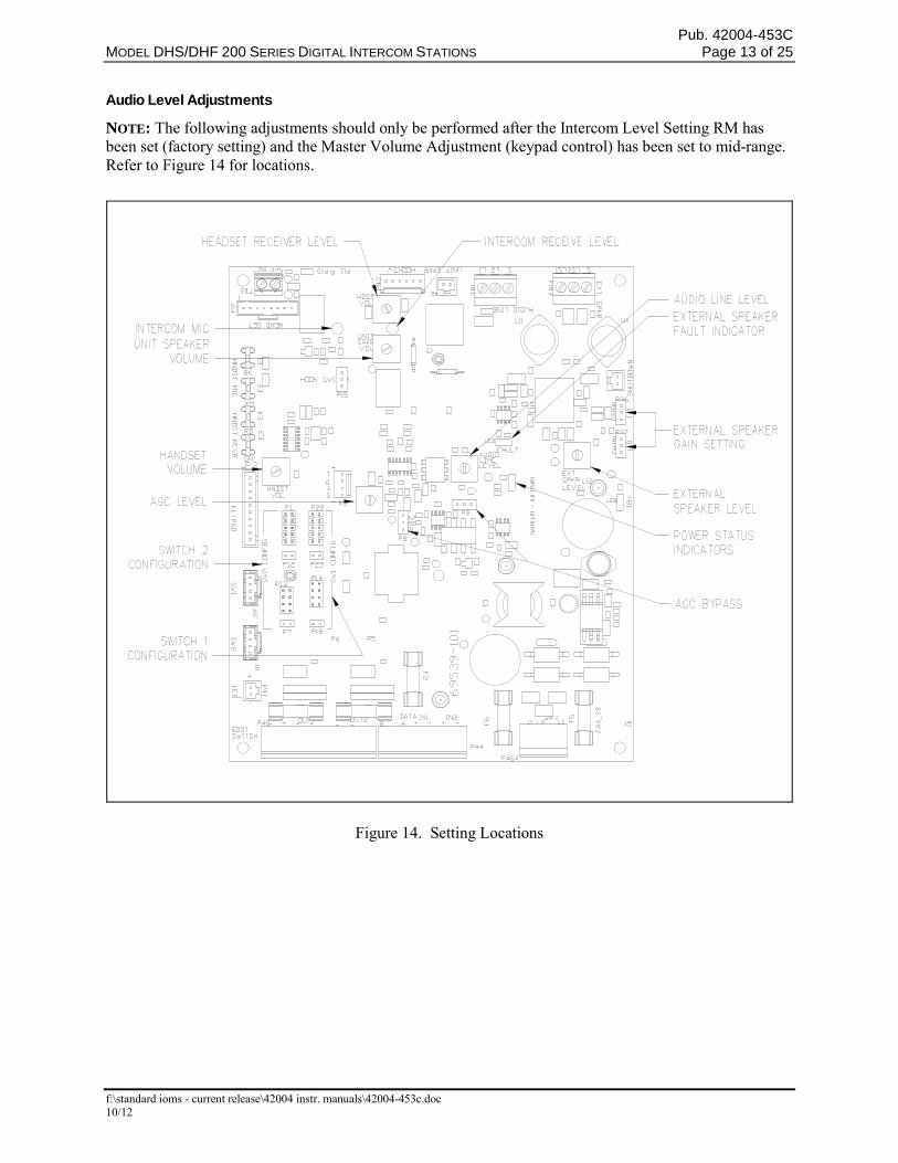
Audio Level Adjustments
NOTE: The following adjustments should only be performed after the Intercom Level Setting RM has been set (factory setting) and the Master Volume Adjustment (keypad control) has been set to mid-range. Refer to Figure 14 for locations.
Figure 14. Setting Locations
Pub. 42004-453C MODEL DHS/DHF 200 SERIES DIGITAL INTERCOM STATIONS Page 14 of 25
f:\standard ioms - current release\42004 instr. manuals\42004-453c.doc 10/12
Handset Receiver Volume
Potentiometer R73 has been provided for individual adjustment of the handset receiver volume. To increase the handset volume, rotate R73 (HNDST VOL) clockwise. To decrease the volume, rotate R73 counterclockwise.
Unit Speaker Level
Potentiometer R75 has been provided for individual adjustment of the unit speaker volume. To increase the speaker volume, rotate R75 (UNIT SPKR VOL) clockwise. To decrease the volume, rotate R75 counterclockwise.
Headset Receiver Level
Potentiometer R79 has been provided for individual adjustment of the headset receiver volume. To increase the headset volume, rotate R79 (HDST VOL) clockwise. To decrease the volume, rotate R79 counterclockwise.
AGC (Automatic Gain Control)
This station is equipped with an automatic gain control circuit in order to minimize level changes on the audio line and the external speaker. The master volume control (keypad) affects the audio level received by this station. The master volume control enables the handset, headset, and unit speaker levels to be controlled via the keypad, but it also affects the audio level supplied to the audio line and external speaker; therefore, an automatic gain control circuit has been added. This adjustment has been factory set and should only be performed by certified Field Service Personnel.
AGC Bypass
If necessary, the AGC circuitry can be bypassed. To bypass the AGC, move the jumpers on P8 and P9 from IN to the OUT position.
NOTE: The following adjustments should only be performed after the Intercom Level Setting RM has been set (factory setting), the Master Volume Adjustment (keypad control) has been set to mid-range, and the AGC has been set.
Pub. 42004-453C MODEL DHS/DHF 200 SERIES DIGITAL INTERCOM STATIONS Page 15 of 25
f:\standard ioms - current release\42004 instr. manuals\42004-453c.doc 10/12
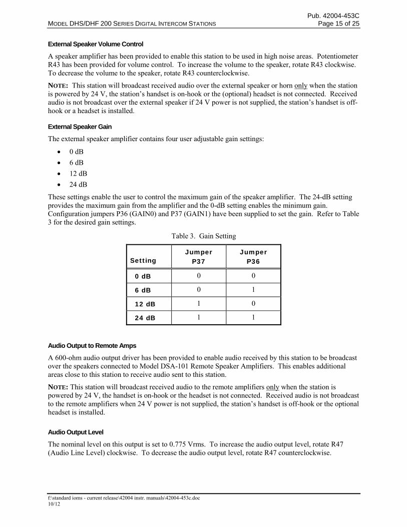
External Speaker Volume Control
A speaker amplifier has been provided to enable this station to be used in high noise areas. Potentiometer R43 has been provided for volume control. To increase the volume to the speaker, rotate R43 clockwise. To decrease the volume to the speaker, rotate R43 counterclockwise.
NOTE: This station will broadcast received audio over the external speaker or horn only when the station is powered by 24 V, the station’s handset is on-hook or the (optional) headset is not connected. Received audio is not broadcast over the external speaker if 24 V power is not supplied, the station’s handset is off-hook or a headset is installed.
External Speaker Gain
The external speaker amplifier contains four user adjustable gain settings:
0 dB
6 dB
12 dB
24 dB
These settings enable the user to control the maximum gain of the speaker amplifier. The 24-dB setting provides the maximum gain from the amplifier and the 0-dB setting enables the minimum gain. Configuration jumpers P36 (GAIN0) and P37 (GAIN1) have been supplied to set the gain. Refer to Table 3 for the desired gain settings.
Table 3. Gain Setting
Setting
Jumper P37
Jumper P36
0 dB 0 0
6 dB 0 1
12 dB 1 0
24 dB 1 1
Audio Output to Remote Amps
A 600-ohm audio output driver has been provided to enable audio received by this station to be broadcast over the speakers connected to Model DSA-101 Remote Speaker Amplifiers. This enables additional areas close to this station to receive audio sent to this station.
NOTE: This station will broadcast received audio to the remote amplifiers only when the station is powered by 24 V, the handset is on-hook or the headset is not connected. Received audio is not broadcast to the remote amplifiers when 24 V power is not supplied, the station’s handset is off-hook or the optional headset is installed.
Audio Output Level
The nominal level on this output is set to 0.775 Vrms. To increase the audio output level, rotate R47 (Audio Line Level) clockwise. To decrease the audio output level, rotate R47 counterclockwise.
Pub. 42004-453C MODEL DHS/DHF 200 SERIES DIGITAL INTERCOM STATIONS Page 16 of 25
f:\standard ioms - current release\42004 instr. manuals\42004-453c.doc 10/12
Switch Configuration
A set of configuration jumpers has been provided for panel switches SW1 and SW2. These configuration jumpers enable switches SW1 or SW2 to be set as a button on the keypad matrix or one of the programmable inputs IN1 or IN2.
SW1
Configuration jumpers labeled R1-R4 and C1-C5 (on P14 and P29) enable switch SW1 to be set as a single button of the keypad matrix. For example: to configure switch SW1 as keypad button 5, install the jumpers on row R2 and column C2. Two configuration jumpers labeled C_GND and IN1 (on P18 and P23) enable switch SW1 to be set as programmable input IN1. To set switch SW1 as input IN1, install the jumpers on C_GND and IN1.
NOTE: The function of input IN1 must be programmed in the central cabinet. Refer to the “Inputs” section of the central cabinet instruction manual for instructions on how to program this input. Also, the footswitch input shares the programmable input IN1 with SW1. Either the footswitch can use programmable input IN1 or SW1, but not both.
SW2
Configuration jumpers labeled R1-R4 and C1-C5 (on P13 and P1) enable switch SW2 to be set as a single button of the keypad matrix. For example: to configure switch SW2 as keypad button 9, install the jumpers on row R3 and column C3. Two configuration jumpers labeled C_GND and IN2 (on P7 and P12) enable switch SW2 to be set as programmable input IN2. To set switch SW2 as input IN2, install the jumpers on C_GND and IN2.
NOTE: The function of input IN2 must be programmed in the central cabinet. Refer to the “Inputs” section of the central cabinet instructional manual for instructions on how to program this input.
Pub. 42004-453C MODEL DHS/DHF 200 SERIES DIGITAL INTERCOM STATIONS Page 17 of 25
f:\standard ioms - current release\42004 instr. manuals\42004-453c.doc 10/12
Inputs
Two programmable inputs (IN1 and IN2) have been provided on this assembly. Inputs IN1 and IN2 can be programmed to perform a variety of functions such as: initiating dialing, changing button functions, initiating alarms, etc. Termination of the input contacts have been provided on terminal block P44 pins 1–4 (IN1 +/−, IN2 +/−).
NOTE: Input IN1 is shared with the footswitch and SW1 inputs; therefore, this input can only be used when the footswitch and SW1 are not in use. Input IN2 is shared with the SW2 input, therefore, this input can only be used when SW2 is not in use. Please refer to the “Inputs” section of the central cabinet instruction manual for instructions on how to program these inputs.
Footswitch A programmable footswitch input has been provided on this assembly. Termination for the input contact has been provided on terminal block P45 pins 7-8 (footswitch +/−). The footswitch can be programmed to perform a variety of functions such as: talk/listen control (T button function), direct dialing, etc. The footswitch input shares the programmable input IN1 with SW1. Either the footswitch can use programmable input IN1 or SW1, but not both.
NOTE: The function of input IN1 must be programmed in the central cabinet. Refer to the “Inputs” section of the central cabinet instruction manual for instructions on how to program this input.
Outputs
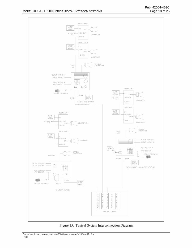
Two programmable opto-coupler outputs (OUT1 and OUT2) have been provided on this assembly. Termination for the output have been provided on terminal block P45 pins 2-3 [OUT2 (−), (+)] and pins 4–5 and [OUT1 (−), (+)]. Outputs OUT1 and OUT2 can be programmed to perform a variety of functions such as: conversation active, loudspeaker active, PA announcement, pre-defined conference active, all call or group call received, door opener, etc. Please refer to the “Outputs” section of the central cabinet instruction manual for instructions on how to program these outputs.
Refer to Figure 15 for a typical system interconnection.
NOTE: The outputs can only be used when the station is powered by 24 V.
Pub. 42004-453C MODEL DHS/DHF 200 SERIES DIGITAL INTERCOM STATIONS Page 18 of 25
f:\standard ioms - current release\42004 instr. manuals\42004-453c.doc 10/12
Figure 15. Typical System Interconnection Diagram
Pub. 42004-453C MODEL DHS/DHF 200 SERIES DIGITAL INTERCOM STATIONS Page 19 of 25
f:\standard ioms - current release\42004 instr. manuals\42004-453c.doc 10/12
Operation Hands-free Operation 2.1. Press a call button located on the front panel. Optional: Use the 16-button keypad to dial the
extension of the desired station. The front panel LED illuminates to indicate a call is in progress.
3.2. Speak into the panel microphone to transmit audio. If necessary, talk/listen control can be controlled using the * button on the keypad or by using the station’s footswitch input.
4.3. Audio is broadcast over the station’s speaker. NOTE: Audio will not be broadcast over the external speaker or remote amplifiers if 24 V power is not supplied.
5.4. Terminate the call by depressing the # button.
Handset Operation 2.1. Using the 16-button keypad, dial the extension of the desired station or press a call button located on
the front panel. The front panel LED illuminates to indicate a call is in progress.
3.2. Speak into the handset microphone. If necessary, talk/listen can be controlled using the * button on the keypad or by using the station’s footswitch input.
3. Audio will be received over the handset receiver. NOTE: Audio will not be broadcast over the handset, external speaker, or Remote Amplifiers whenever the optional headset is installed or if 24 V power is not supplied.
4. Terminate the call by depressing the # button or placing the handset on hook.
5. If an incoming call (or page, alarm, or music) is received while the handset is on hook, the audio is broadcast over the station’s speaker. The external speaker and the remote amplifiers will also broadcast the audio if 24 V power is supplied to the unit. If the handset is off hook, then audio is broadcast over the handset receiver.
Pub. 42004-453C MODEL DHS/DHF 200 SERIES DIGITAL INTERCOM STATIONS Page 20 of 25
f:\standard ioms - current release\42004 instr. manuals\42004-453c.doc 10/12
Headset Operation NOTE: 24 V power is required.
1. Connect the headset to the eight-pin headset jack on the front panel.
2. Using the 16-button keypad, dial the extension of the desired station. Optional - Press a call button located on the front panel. The front panel LED illuminates to indicate a call in progress.
3. Speak into the headset microphone to transmit audio. If necessary, talk/listen control can be controlled using the * button on the keypad or by using the station’s footswitch input.
4. Audio is received over the headset receiver. NOTE: Audio will not broadcast over the handset, external speaker, or Remote Amplifiers whenever the headset is installed.
5. Terminate the call by depressing the # button.
6. If an incoming call, page, alarm, or music arrives while the headset is connected, the audio will be broadcast over the headset receiver but will not broadcast over the station’s speaker, the external speaker, or the Remote Amplifiers.
Paging This station is capable of sending and receiving all-calls and group calls. Refer to the “All-Call” and “Group Call” sections of the central cabinet instruction manual for configuration details. Hands-free stations will broadcast pages over the external speaker and remote amplifiers.
NOTE Pages are not broadcast over the external speaker and Remote Amplifiers whenever the handset is off hook or the optional headset is installed or 24 V power is not supplied.
Alarms and Music This station is capable of receiving alarms and music. Refer to the “Alarms” and “Music” sections of the central cabinet instruction manual for configuration details. Hands-free stations will broadcast alarms and music over the external speaker and remote amplifiers.
NOTE Alarms and music will not broadcast over the external speaker and remote amplifiers whenever the handset is off-hook, the optional headset is installed, or 24 V power is not supplied.
Pub. 42004-453C MODEL DHS/DHF 200 SERIES DIGITAL INTERCOM STATIONS Page 21 of 25
f:\standard ioms - current release\42004 instr. manuals\42004-453c.doc 10/12
Status Indication
Call Status
A status LED is provided on the front panel to indicate the call status. This LED is normally active when a conversation is enabled. For additional status information, refer to the central cabinet instruction manual.
Controls Keypad
The keypad performs a variety of functions such as: dialing, talk/listen control, call cancel, volume control, etc. For handset stations, you must go off hook prior to dialing.
Single Button Dialing
A single button or button sequence can be dialed to call another station. Press the pre-programmed keypad sequence to initiate dialing. For handset stations, you must go off-hook prior to dialing. Refer to the “Direct Dialing” section of the central cabinet instruction manual for instructions on how to program these buttons.
Talk/Listen Control
The * button can be used to control talk/listen switching. This button can be programmed to press and hold or touch and go. When using press and hold control, press and hold the * button when speaking and release to listen. When using touch and go control, press and release the * button each time you want to speak. Handset stations must be off hook in order to use this function. Refer to the “* Button” section of the central cabinet manual for instructions on how to program this button.
Call Cancel
The # button can be used to cancel the call. For handset stations, the call is cancelled when you place the handset on hook.
Master Volume
The volume level to the station’s speaker, unit handset, or unit headset can be adjusted using the keypad. The volume level will increase each time the B is pressed until the maximum volume limit is reached. The volume level will decrease each time the A is pressed until the minimum volume limit is reached. To save the volume setting, press the C button.
NOTE: This is a master volume control that affects the volume of the station’s speaker, unit handset or unit headset. This control may affect the audio line level and the external speaker volume for units that have the AGC disabled.
Pub. 42004-453C MODEL DHS/DHF 200 SERIES DIGITAL INTERCOM STATIONS Page 22 of 25
f:\standard ioms - current release\42004 instr. manuals\42004-453c.doc 10/12
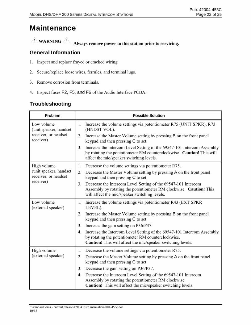
Maintenance WARNING Always remove power to this station prior to servicing.
General Information 1. Inspect and replace frayed or cracked wiring.
2. Secure/replace loose wires, ferrules, and terminal lugs.
3. Remove corrosion from terminals.
4. Inspect fuses F2, F5, and F6 of the Audio Interface PCBA.
Troubleshooting
Problem Possible Solution
Low volume (unit speaker, handset receiver, or headset receiver)
1. Increase the volume settings via potentiometer R75 (UNIT SPKR), R73 (HNDST VOL).
2. Increase the Master Volume setting by pressing B on the front panel keypad and then pressing C to set.
3. Increase the Intercom Level Setting of the 69547-101 Intercom Assembly by rotating the potentiometer RM counterclockwise. Caution! This will affect the mic/speaker switching levels.
High volume (unit speaker, handset receiver, or headset receiver)
1. Decrease the volume settings via potentiometer R75.
2. Decrease the Master Volume setting by pressing A on the front panel keypad and then pressing C to set.
3. Decrease the Intercom Level Setting of the 69547-101 Intercom Assembly by rotating the potentiometer RM clockwise. Caution! This will affect the mic/speaker switching levels.
Low volume (external speaker)
1. Increase the volume settings via potentiometer R43 (EXT SPKR LEVEL).
2. Increase the Master Volume setting by pressing B on the front panel keypad and then pressing C to set.
3. Increase the gain setting on P36/P37.
4. Increase the Intercom Level Setting of the 69547-101 Intercom Assembly by rotating the potentiometer RM counterclockwise. Caution! This will affect the mic/speaker switching levels.
High volume (external speaker)
1. Decrease the volume settings via potentiometer R75.
2. Decrease the Master Volume setting by pressing A on the front panel keypad and then pressing C to set.
3. Decrease the gain setting on P36/P37.
4. Decrease the Intercom Level Setting of the 69547-101 Intercom Assembly by rotating the potentiometer RM clockwise. Caution! This will affect the mic/speaker switching levels.
Pub. 42004-453C MODEL DHS/DHF 200 SERIES DIGITAL INTERCOM STATIONS Page 23 of 25
f:\standard ioms - current release\42004 instr. manuals\42004-453c.doc 10/12
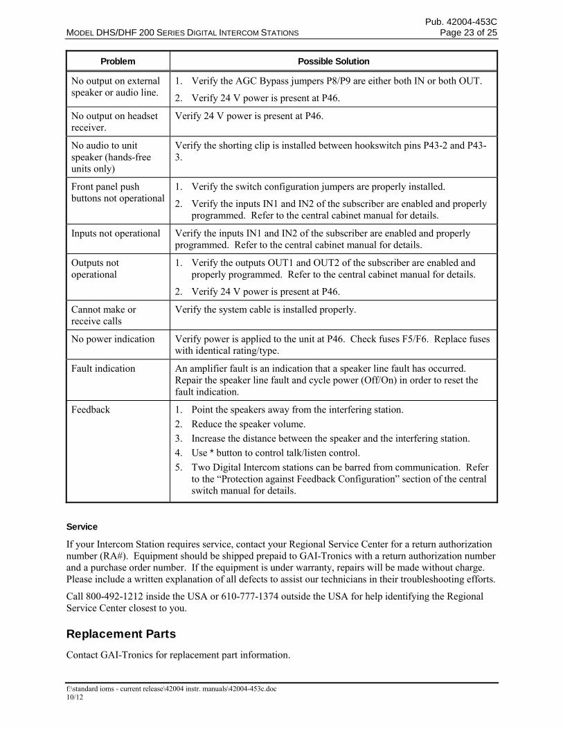
Problem Possible Solution
No output on external speaker or audio line.
1. Verify the AGC Bypass jumpers P8/P9 are either both IN or both OUT.
2. Verify 24 V power is present at P46.
No output on headset receiver.
Verify 24 V power is present at P46.
No audio to unit speaker (hands-free units only)
Verify the shorting clip is installed between hookswitch pins P43-2 and P43-3.
Front panel push buttons not operational
1. Verify the switch configuration jumpers are properly installed.
2. Verify the inputs IN1 and IN2 of the subscriber are enabled and properly programmed. Refer to the central cabinet manual for details.
Inputs not operational Verify the inputs IN1 and IN2 of the subscriber are enabled and properly programmed. Refer to the central cabinet manual for details.
Outputs not operational
1. Verify the outputs OUT1 and OUT2 of the subscriber are enabled and properly programmed. Refer to the central cabinet manual for details.
2. Verify 24 V power is present at P46.
Cannot make or receive calls
Verify the system cable is installed properly.
No power indication Verify power is applied to the unit at P46. Check fuses F5/F6. Replace fuses with identical rating/type.
Fault indication An amplifier fault is an indication that a speaker line fault has occurred. Repair the speaker line fault and cycle power (Off/On) in order to reset the fault indication.
Feedback 1. Point the speakers away from the interfering station.
2. Reduce the speaker volume.
3. Increase the distance between the speaker and the interfering station.
4. Use * button to control talk/listen control.
5. Two Digital Intercom stations can be barred from communication. Refer to the “Protection against Feedback Configuration” section of the central switch manual for details.
Service
If your Intercom Station requires service, contact your Regional Service Center for a return authorization number (RA#). Equipment should be shipped prepaid to GAI-Tronics with a return authorization number and a purchase order number. If the equipment is under warranty, repairs will be made without charge. Please include a written explanation of all defects to assist our technicians in their troubleshooting efforts.
Call 800-492-1212 inside the USA or 610-777-1374 outside the USA for help identifying the Regional Service Center closest to you.
Replacement Parts Contact GAI-Tronics for replacement part information.
Pub. 42004-453C MODEL DHS/DHF 200 SERIES DIGITAL INTERCOM STATIONS Page 24 of 25
f:\standard ioms - current release\42004 instr. manuals\42004-453c.doc 10/12
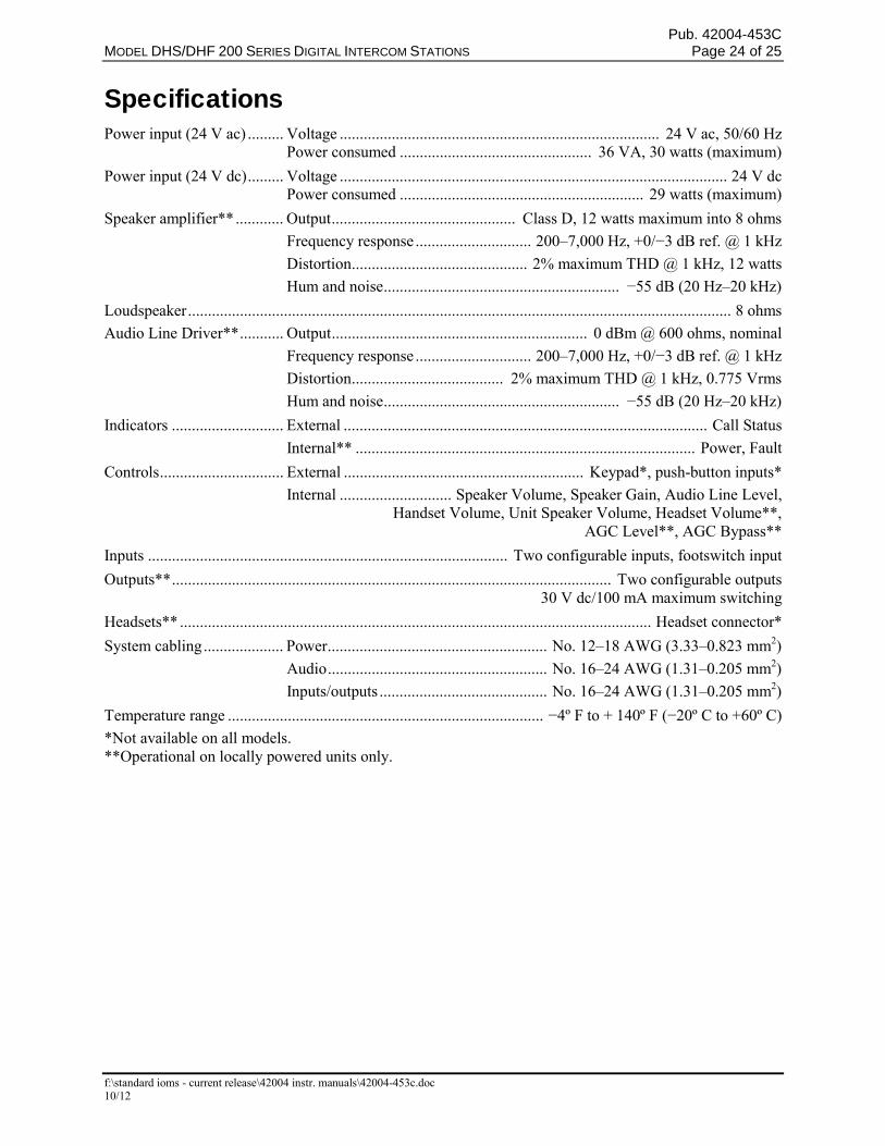
Specifications Power input (24 V ac) ......... Voltage ................................................................................ 24 V ac, 50/60 Hz Power consumed ................................................ 36 VA, 30 watts (maximum)
Power input (24 V dc) ......... Voltage ................................................................................................. 24 V dc Power consumed ............................................................. 29 watts (maximum)
Speaker amplifier** ............ Output .............................................. Class D, 12 watts maximum into 8 ohms
Frequency response ............................. 200–7,000 Hz, +0/−3 dB ref. @ 1 kHz
Distortion ............................................ 2% maximum THD @ 1 kHz, 12 watts
Hum and noise ........................................................... −55 dB (20 Hz–20 kHz)
Loudspeaker ........................................................................................................................................ 8 ohms
Audio Line Driver** ........... Output ................................................................ 0 dBm @ 600 ohms, nominal
Frequency response ............................. 200–7,000 Hz, +0/−3 dB ref. @ 1 kHz
Distortion ...................................... 2% maximum THD @ 1 kHz, 0.775 Vrms
Hum and noise ........................................................... −55 dB (20 Hz–20 kHz)
Indicators ............................ External ........................................................................................... Call Status
Internal** ..................................................................................... Power, Fault
Controls ............................... External ............................................................ Keypad*, push-button inputs*
Internal ............................ Speaker Volume, Speaker Gain, Audio Line Level, Handset Volume, Unit Speaker Volume, Headset Volume**, AGC Level**, AGC Bypass**
Inputs .......................................................................................... Two configurable inputs, footswitch input
Outputs** .............................................................................................................. Two configurable outputs 30 V dc/100 mA maximum switching
Headsets** ...................................................................................................................... Headset connector*
System cabling .................... Power ....................................................... No. 12–18 AWG (3.33–0.823 mm2)
Audio ....................................................... No. 16–24 AWG (1.31–0.205 mm2)
Inputs/outputs .......................................... No. 16–24 AWG (1.31–0.205 mm2)
Temperature range ............................................................................... −4º F to + 140º F (−20º C to +60º C)
*Not available on all models. **Operational on locally powered units only.
Pub. 42004-453C MODEL DHS/DHF 200 SERIES DIGITAL INTERCOM STATIONS Page 25 of 25
f:\standard ioms - current release\42004 instr. manuals\42004-453c.doc 10/12
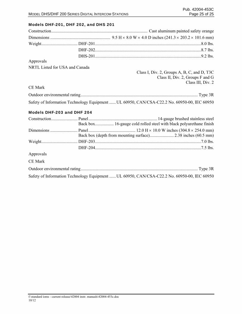
Models DHF-201, DHF 202, and DHS 201 Construction ........................................................................................ Cast aluminum painted safety orange
Dimensions ....................................................... 9.5 H 8.0 W 4.0 D inches (241.3 203.2 101.6 mm)
Weight ................................. DHF-201................................................................................................. 8.0 lbs.
DHF-202................................................................................................. 8.7 lbs.
DHS-201................................................................................................. 9.2 lbs. Approvals
NRTL Listed for USA and Canada Class I, Div. 2, Groups A, B, C, and D, T3C Class II, Div. 2, Groups F and G Class III, Div. 2 CE Mark
Outdoor environmental rating ........................................................................................................... Type 3R
Safety of Information Technology Equipment ...... UL 60950, CAN/CSA-C22.2 No. 60950-00, IEC 60950
Models DHF-203 and DHF 204 Construction ........................ Panel ............................................................... 14-gauge brushed stainless steel Back box ................. 16-gauge cold rolled steel with black polyurethane finish
Dimensions ......................... Panel ........................................... 12.0 H 10.0 W inches (304.8 254.0 mm) Back box (depth from mounting surface) ...................... 2.38 inches (60.5 mm)
Weight ................................. DHF-203................................................................................................. 7.0 lbs.
DHF-204................................................................................................. 7.5 lbs.
Approvals
CE Mark
Outdoor environmental rating ........................................................................................................... Type 3R
Safety of Information Technology Equipment ...... UL 60950, CAN/CSA-C22.2 No. 60950-00, IEC 60950
(Rev. 10/06)
WarrantyEquipment. GAI-Tronics warrants for a period of one (1) year from the date of shipment, that anyGAI-Tronics equipment supplied hereunder shall be free of defects in material and workmanship, shallcomply with the then-current product specifications and product literature, and if applicable, shall be fitfor the purpose specified in the agreed-upon quotation or proposal document. If (a) Seller’s goods proveto be defective in workmanship and/or material under normal and proper usage, or unfit for the purposespecified and agreed upon, and (b) Buyer’s claim is made within the warranty period set forth above,Buyer may return such goods to GAI-Tronics’ nearest depot repair facility, freight prepaid, at which timethey will be repaired or replaced, at Seller’s option, without charge to Buyer. Repair or replacement shallbe Buyer’s sole and exclusive remedy. The warranty period on any repaired or replacement equipmentshall be the greater of the ninety (90) day repair warranty or one (1) year from the date the originalequipment was shipped. In no event shall GAI-Tronics warranty obligations with respect to equipmentexceed 100% of the total cost of the equipment supplied hereunder. Buyer may also be entitled to themanufacturer’s warranty on any third-party goods supplied by GAI-Tronics hereunder. The applicabilityof any such third-party warranty will be determined by GAI-Tronics.
Services. Any services GAI-Tronics provides hereunder, whether directly or through subcontractors,shall be performed in accordance with the standard of care with which such services are normallyprovided in the industry. If the services fail to meet the applicable industry standard, GAI-Tronics willre-perform such services at no cost to buyer to correct said deficiency to Company's satisfaction providedany and all issues are identified prior to the demobilization of the Contractor’s personnel from the worksite. Re-performance of services shall be Buyer’s sole and exclusive remedy, and in no event shall GAI-Tronics warranty obligations with respect to services exceed 100% of the total cost of the servicesprovided hereunder.
Warranty Periods. Every claim by Buyer alleging a defect in the goods and/or services providedhereunder shall be deemed waived unless such claim is made in writing within the applicable warrantyperiods as set forth above. Provided, however, that if the defect complained of is latent and notdiscoverable within the above warranty periods, every claim arising on account of such latent defect shallbe deemed waived unless it is made in writing within a reasonable time after such latent defect is orshould have been discovered by Buyer.
Limitations / Exclusions. The warranties herein shall not apply to, and GAI-Tronics shall not beresponsible for, any damage to the goods or failure of the services supplied hereunder, to the extentcaused by Buyer’s neglect, failure to follow operational and maintenance procedures provided with theequipment, or the use of technicians not specifically authorized by GAI-Tronics to maintain or service theequipment. THE WARRANTIES AND REMEDIES CONTAINED HEREIN ARE IN LIEU OF ANDEXCLUDE ALL OTHER WARRANTIES AND REMEDIES, WHETHER EXPRESS OR IMPLIED BYOPERATION OF LAW OR OTHERWISE, INCLUDING ANY WARRANTIES OFMERCHANTABILITY OR FITNESS FOR A PARTICULAR PURPOSE.
Return PolicyIf the equipment requires service, contact your Regional Service Center for a return authorization number(RA#). Equipment should be shipped prepaid to GAI-Tronics with a return authorization number and apurchase order number. If the equipment is under warranty, repairs or a replacement will be made inaccordance with the warranty policy set forth above. Please include a written explanation of all defects toassist our technicians in their troubleshooting efforts.
Call 800-492-1212 (inside the USA) or 610-777-1374 (outside the USA) for help identifying theRegional Service Center closest to you.