Embed Size (px)
Citation preview
IT: Computer Maintenance: PC Disassembly and Reassembly Plan Copyright © Texas Education Agency, 2011. All rights reserved.
1
Lesson Plan Course Title: Computer Maintenance
Session Title: PC Disassembly and Reassembly
Lesson Duration: Lesson length is subjective and will vary from instructor to instructor
Performance Objective: Upon completion of this assignment, students will be able to physically disassemble and reassemble a PC. Specific Objectives:
• Boot up the PC to be disassembled and reassembled [verify that it works properly]. • Disassemble a PC. • Reassemble a PC. • Boot up the reassembled PC [verify that it works properly]. • Identify safety guidelines related to the lesson. • List the steps in opening a PC. • Identify the internal components of a PC. • Diagram the internal components of a PC. • Disassemble a PC. • Reassemble a PC.
Preparation
TEKS Correlations: §130.273. Computer Maintenance (C)(4)(D) (The student acquires an understanding of computer technologies. The student is expected to: explain proper troubleshooting techniques as related to computer hardware; 130.273(c) (5) (A) (5) The student knows the proper function and application of the tools, equipment, and materials used in computer technologies. The student is expected to:
(A) demonstrate safe use of equipment in computer technologies such as hand and power tools
130.273 (6)(C)(D)(E) (6) The student applies the concepts and skills of the trade in simulated work situations. The student is expected to: (C) identify the operational features and proper terminology related to computer systems; (D) identify the various components of a computer system such as the central processor, basic input and output system, read-only memory, 130.273 (7)(A)(D)(E) (7) The student uses hardware design, operation, and maintenance knowledge and skills to provide computer support. The student is expected to: (A) identify the purpose and function of computer components in the operation of the computer system such as central processing unit, mother board, sockets, chipsets, basic
IT: Computer Maintenance: PC Disassembly and Reassembly Plan Copyright © Texas Education Agency, 2011. All rights reserved.
2
input and output system and their drivers, memory, hard drive technologies, video cards, input and output devices and ports, and modem and network interface cards (NIC);
(D) assemble and install a basic computer system; and (E) install and configure computer components and peripherals. Instructor/Trainer References:
1. Cisco Systems Sponsored Curriculum: IT Essentials I: PC Hardware and Software, Chapter 3: Assembling a Computer.
2. http://www.youtube.com/watch?v=rdsUuWlhOvo&feature=related 3. http://www.youtube.com/watch?v=ZQH9L9fsdRg&feature=related 4. http://www.worldstart.com/tips/tips.php/3046 5. http://www.bedford.k12.va.us/fms/lessons/ 6. http://www.lessonplanspage.com/index.html 7. http://www.homepcbuilder.com/video-lessons/internal-components/lesson-01-hard-drive-
building-your-own-computer.html Instructional Aids:
1. PC Disassembly and Reassembly: PowerPoint presentation 2. PC Disassembly and Reassembly: PowerPoint presentation Handouts 3. The online tutorials for assembling and reassembling 4. Disassembling/Assembling a PC Performance Aid 5. Lab Sheets for Disassembly and Reassembly of a PC (LABS 1 & 2) 6. PC Disassembly and Reassembly Exam 7. PC Internal Architecture Evaluation Rubric
Materials Needed:
1. Containers 2. Clean work area 3. Pencil (one per student) 4. Graph paper 5. Standard computer technician tool kit (with wrist-strap) [for each pair of students] 6. Copies of Lab Sheet for Disassembly and Reassembly of a PC [for each student]
Equipment Needed:
1. A projection system to display the PowerPoint presentation [PC/Monitor, PC/Projector, etc.] and online tutorial
2. One PC for each two students, for labs. 3. PC tool kit 4. Antistatic wrist strap 5. Chip extractor
Learner
1. Students should read the appropriate curriculum material for how to disassemble/assemble a PC [depending on the text/curriculum being used for this course]. This lesson can be taught with only the PowerPoint presentation, and the equipment outlined above.
IT: Computer Maintenance: PC Disassembly and Reassembly Plan Copyright © Texas Education Agency, 2011. All rights reserved.
3
Introduction
MI Introduction (LSI Quadrant I):
Understanding how a PC is assembled and disassembled is a key component in the training for a computer technician. Knowledge of how the computer parts “fit” will help the technician solve repair and upgrade problems.
IDE storage devices, such as the hard drive and CD-ROM drive, are the most common type of storage devices installed in today’s PC. How can the computer technician ensure the cabling for these devices is properly oriented? Make sure that the colored stripe [usually red, sometimes blue] is oriented on the number 1 pin of the IDE port [both on the motherboard and the drive]. On the drive’s IDE port, the number one pin is usually closest to the power connector.
Outline
MI Outline (LSI Quadrant II): Instructor Notes:
I. Introduce students to the computer assembly process to include A. Computer chassis (case) B. Power supply C. Motherboard configuration D. Configuration of connectors E. CPU interfaces F. RAM installation G. Hard drives and/or CD-ROMs installation H. Floppy drives connection I. First boot after assembly
II. Safety guidelines
A. Make sure workspace is clean and properly lit.
B. Make sure the PC is turned off. C. Verify that the PC has been unplugged
from the power source. D. Put on antistatic wrist strap. E. Create a backup of the PC configuration
(most PCs will restore and reboot themselves).
III. Steps in opening a CPU
A. Note the type of PC being worked on (manufacturer, model, hard drive capacity/space, external location of hard drive).
B. Remove the power cord from the monitor, then unplug, unscrew the monitor cable from the back of the PC, and set the
IT: Computer Maintenance: PC Disassembly and Reassembly Plan Copyright © Texas Education Agency, 2011. All rights reserved.
4
monitor aside. C. Locate the screws on the back side of the
case. D. Remove the screws and place them in a
tube container for safe keeping. E. Carefully remove the case, watching out for
internal wires and cables. IV. Internal PC components
A. Near the front of the case one or more of the following:
1. Shelf bracket 2. Floppy drive 3. Hard drive 4. Zip drive 5. CD-R 6. DVD/CD-R 7. DVD/CD-RW
B. Directly below or to the right of the shelf bracket
1. Motherboard a. CPU (Athlon or Pentium chip) b. Memory Modules (SIMM, DIMMS,
or RIMM chips) c. Buses (small wires that allow
information to flow through the PC) d. Transistors e. Resistors
C. Attached to the motherboard 1. Expansion cards
a. Internet (via modem or Ethernet) b. Enhanced graphics cards (AGP 4
or 5) c. PCTV card (allows images to be
projected to a TV – in some PCs) d. USB ports e. FireWire ports f. Audio ports g. Parallel ports h. Serial ports i. Keyboard port j. Mouse port
D. Toward the back of the case 1. Power supply
V. Diagramming internal PC components
A. Symbols B. Cables/connections C. Plug locations/configurations/types D. DIP switch locations/status E. Motherboard: memory sockets, switches,
IT: Computer Maintenance: PC Disassembly and Reassembly Plan Copyright © Texas Education Agency, 2011. All rights reserved.
5
power supply connection F. Labels G. Legend H. Scale
VI. Steps in disassembling a PC
A. Note and record each part, drive, cable, and connection.
B. Avoid forcing the removal of parts (if they don’t come out easily; STOP and assess why).
C. Remove the drives with their connecting cables (makes the job easier by allowing more room for work).
D. Place the removed parts in a separate space on the work area.
E. Remove the expansion cards, noting the bays in which they were originally located.
F. DO NOT TOUCH the pin connectors on the cards with your bare hands.
G. Unplug and carefully remove the power supply from the machine. EXTRA CARE should be taken with the power supply as it still has a power charge in it.
H. Gently remove the CPU from the Motherboard by unlocking the ZIF or LIZ (Zero Insertion Force) socket. If the CPU is in a push-in socket, then use the CPU removal tool that comes in the kit. Note the position prior to removal to prevent damage when reassembling.
I. Carefully remove the Motherboard if needed. Check to see if this is necessary (ask your instructor if you are in doubt).
J. Evaluate the removed components as needed, and note all information for future reference.
VII. Reassembling a PC
A. If all parts are found to be in good condition, the student can begin reassembling the PC using the diagram created during disassembly.
VIII. Steps in closing a PC
A. Replace the case, watching out for internal wires and cables.
B. Replace the screws removed earlier. C. Plug in the power source. D. Turn on and reboot the machine to make
sure the PC works properly.
IT: Computer Maintenance: PC Disassembly and Reassembly Plan Copyright © Texas Education Agency, 2011. All rights reserved.
6
IX. Students complete lab demonstrations
including: A. Lab 1: Disassembly of PC B. Lab 2: Reassembly of PC
Application
MI Guided Practice (LSI Quadrant III):
1. The teacher shows and demonstrates each lab principle. 2. The teacher maintains direct supervision in the lab, providing guidance when
warranted.
The teacher will demonstrate how to open a PC; identify the internal components; diagram the internal components; disassemble a PC; reassemble a PC; and close a PC following the procedure listed in the outline. The students will work individually or in pairs to identify, diagram, and disassemble the internal components located in the assigned PC, following the example illustrated by the teacher in the Guided Practice portion of the lesson. Students may refer to the Disassembling/Reassembling a PC Performance Aid to prompt the teacher as to which step should be taken at what time.
MI Independent Practice (LSI Quadrant III):
1. Students work in pairs on lab assignments, demonstrating their skills in identifying and discussing the various lab requirements and results.
Summary
MI Review (LSI Quadrants I and IV):
1. Ask students summary questions. a. What are the main types of computer cases? [Desktop, mini-tower, mid-
tower, and full tower] b. What are the two types of power supplies? [AT and ATX] c. What is the voltage for the red and yellow wires of a power connector?
[Red is 5 volts and yellow is 12 volts] 2. Revisit the steps the students went through to reassemble the PC.
Evaluation
MI Informal Assessment (LSI Quadrant III):
1. The teacher will monitor student progress during independent practice and provide independent re-teach/redirection as needed.
2. The teacher will provide individual help/redirection as needed.
MI Formal Assessment (LSI Quadrant III, IV):
1. The students will individually demonstrate the ability to open/close a PC while
adhering to all safety guidelines. Use the Disassembling/Reassembling A PC
IT: Computer Maintenance: PC Disassembly and Reassembly Plan Copyright © Texas Education Agency, 2011. All rights reserved.
7
Evaluation Rubric to evaluate students. The students will also submit schematic drawings of the assigned PCs for evaluation.
2. Administer the PC Exam.
Extension
MI Extension/Enrichment (LSI Quadrant IV):
1. Students who have mastered the lab assignments can peer-tutor students [one-on-one] that are having difficulty with the disassembly or assembly of the PC.
2. Have students convert hand-drawn schematic drawings to AutoCAD drawings to create an electronic database for reference purposes.
3. Students who have mastered the skills associated with this lesson may be called upon to help maintain other computers throughout the building by making related repairs as required.
IT: Computer Maintenance: PC Disassembly and Reassembly Plan Copyright © Texas Education Agency, 2011. All rights reserved.
8
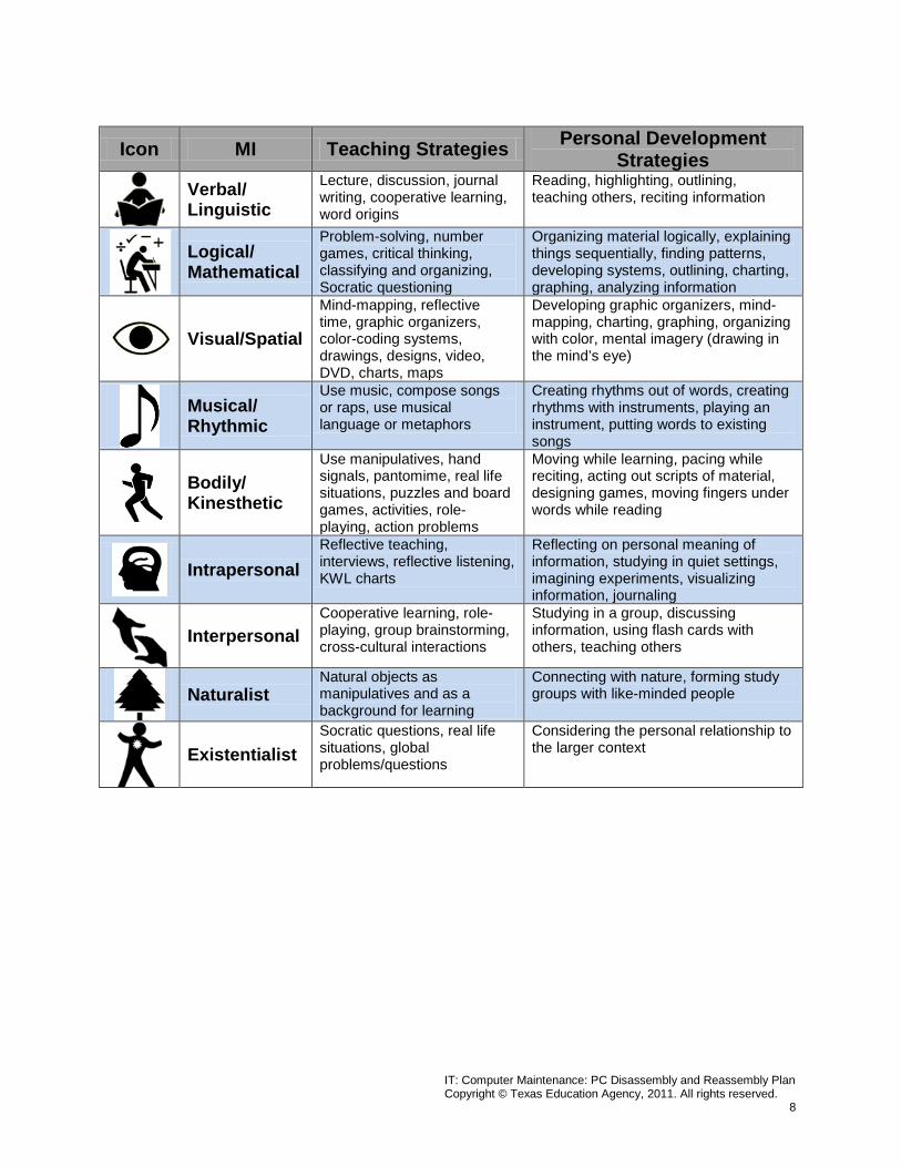
Icon MI Teaching Strategies Personal Development Strategies
Verbal/ Linguistic
Lecture, discussion, journal writing, cooperative learning, word origins
Reading, highlighting, outlining, teaching others, reciting information
Logical/ Mathematical
Problem-solving, number games, critical thinking, classifying and organizing, Socratic questioning
Organizing material logically, explaining things sequentially, finding patterns, developing systems, outlining, charting, graphing, analyzing information
Visual/Spatial
Mind-mapping, reflective time, graphic organizers, color-coding systems, drawings, designs, video, DVD, charts, maps
Developing graphic organizers, mind-mapping, charting, graphing, organizing with color, mental imagery (drawing in the mind’s eye)
Musical/ Rhythmic
Use music, compose songs or raps, use musical language or metaphors
Creating rhythms out of words, creating rhythms with instruments, playing an instrument, putting words to existing songs
Bodily/ Kinesthetic
Use manipulatives, hand signals, pantomime, real life situations, puzzles and board games, activities, role-playing, action problems
Moving while learning, pacing while reciting, acting out scripts of material, designing games, moving fingers under words while reading
Intrapersonal
Reflective teaching, interviews, reflective listening, KWL charts
Reflecting on personal meaning of information, studying in quiet settings, imagining experiments, visualizing information, journaling
Interpersonal
Cooperative learning, role-playing, group brainstorming, cross-cultural interactions
Studying in a group, discussing information, using flash cards with others, teaching others
Naturalist
Natural objects as manipulatives and as a background for learning
Connecting with nature, forming study groups with like-minded people
Existentialist
Socratic questions, real life situations, global problems/questions
Considering the personal relationship to the larger context
IT: Computer Maintenance: PC Disassembly and Reassembly Plan Copyright © Texas Education Agency, 2011. All rights reserved.
9
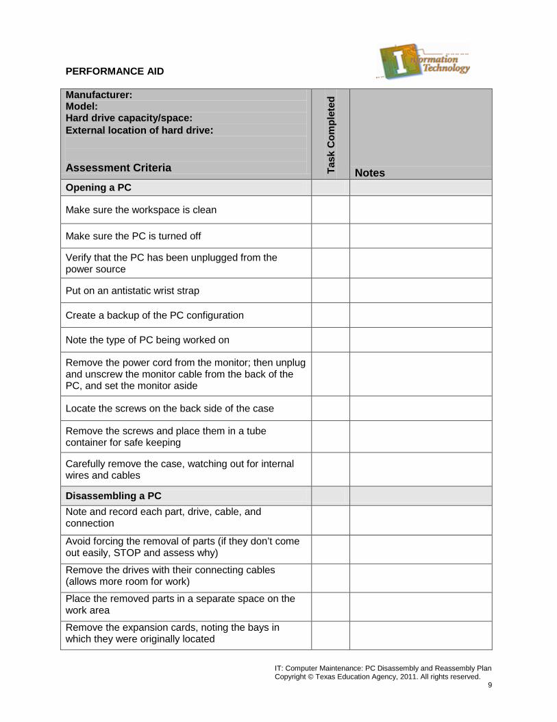
PERFORMANCE AID Manufacturer: Model: Hard drive capacity/space: External location of hard drive: Assessment Criteria Ta
sk C
ompl
eted
Notes Opening a PC
Make sure the workspace is clean
Make sure the PC is turned off
Verify that the PC has been unplugged from the power source
Put on an antistatic wrist strap
Create a backup of the PC configuration
Note the type of PC being worked on
Remove the power cord from the monitor; then unplug and unscrew the monitor cable from the back of the PC, and set the monitor aside
Locate the screws on the back side of the case
Remove the screws and place them in a tube container for safe keeping
Carefully remove the case, watching out for internal wires and cables
Disassembling a PC Note and record each part, drive, cable, and connection
Avoid forcing the removal of parts (if they don’t come out easily, STOP and assess why)
Remove the drives with their connecting cables (allows more room for work)
Place the removed parts in a separate space on the work area
Remove the expansion cards, noting the bays in which they were originally located
IT: Computer Maintenance: PC Disassembly and Reassembly Plan Copyright © Texas Education Agency, 2011. All rights reserved.
10
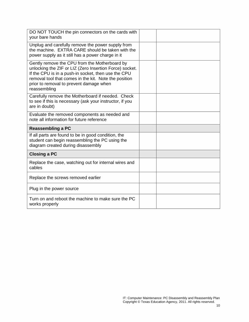
DO NOT TOUCH the pin connectors on the cards with your bare hands
Unplug and carefully remove the power supply from the machine. EXTRA CARE should be taken with the power supply as it still has a power charge in it
Gently remove the CPU from the Motherboard by unlocking the ZIF or LIZ (Zero Insertion Force) socket. If the CPU is in a push-in socket, then use the CPU removal tool that comes in the kit. Note the position prior to removal to prevent damage when reassembling
Carefully remove the Motherboard if needed. Check to see if this is necessary (ask your instructor, if you are in doubt)
Evaluate the removed components as needed and note all information for future reference
Reassembling a PC If all parts are found to be in good condition, the student can begin reassembling the PC using the diagram created during disassembly
Closing a PC
Replace the case, watching out for internal wires and cables
Replace the screws removed earlier
Plug in the power source
Turn on and reboot the machine to make sure the PC works properly
IT: Computer Maintenance: PC Disassembly and Reassembly Plan Copyright © Texas Education Agency, 2011. All rights reserved.
11
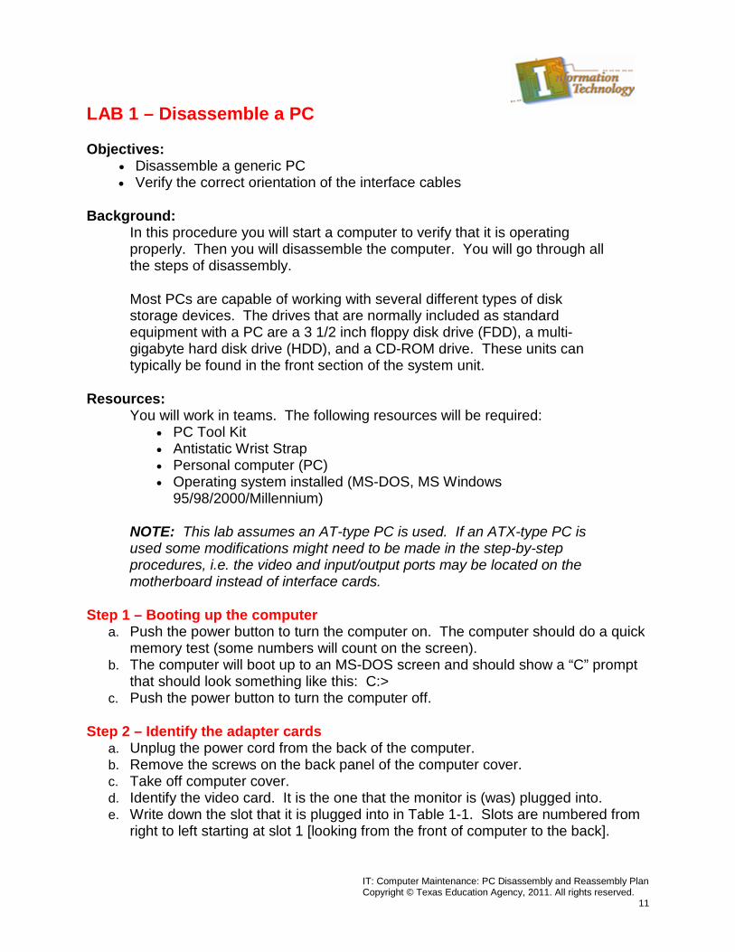
LAB 1 – Disassemble a PC
Objectives: • Disassemble a generic PC • Verify the correct orientation of the interface cables
Background: In this procedure you will start a computer to verify that it is operating properly. Then you will disassemble the computer. You will go through all the steps of disassembly.
Most PCs are capable of working with several different types of disk storage devices. The drives that are normally included as standard equipment with a PC are a 3 1/2 inch floppy disk drive (FDD), a multi-gigabyte hard disk drive (HDD), and a CD-ROM drive. These units can typically be found in the front section of the system unit.
Resources: You will work in teams. The following resources will be required:
• PC Tool Kit • Antistatic Wrist Strap • Personal computer (PC) • Operating system installed (MS-DOS, MS Windows
95/98/2000/Millennium)
NOTE: This lab assumes an AT-type PC is used. If an ATX-type PC is used some modifications might need to be made in the step-by-step procedures, i.e. the video and input/output ports may be located on the motherboard instead of interface cards.
Step 1 – Booting up the computer a. Push the power button to turn the computer on. The computer should do a quick
memory test (some numbers will count on the screen). b. The computer will boot up to an MS-DOS screen and should show a “C” prompt
that should look something like this: C:> c. Push the power button to turn the computer off.
Step 2 – Identify the adapter cards a. Unplug the power cord from the back of the computer. b. Remove the screws on the back panel of the computer cover. c. Take off computer cover. d. Identify the video card. It is the one that the monitor is (was) plugged into. e. Write down the slot that it is plugged into in Table 1-1. Slots are numbered from
right to left starting at slot 1 [looking from the front of computer to the back].
IT: Computer Maintenance: PC Disassembly and Reassembly Plan Copyright © Texas Education Agency, 2011. All rights reserved.
12
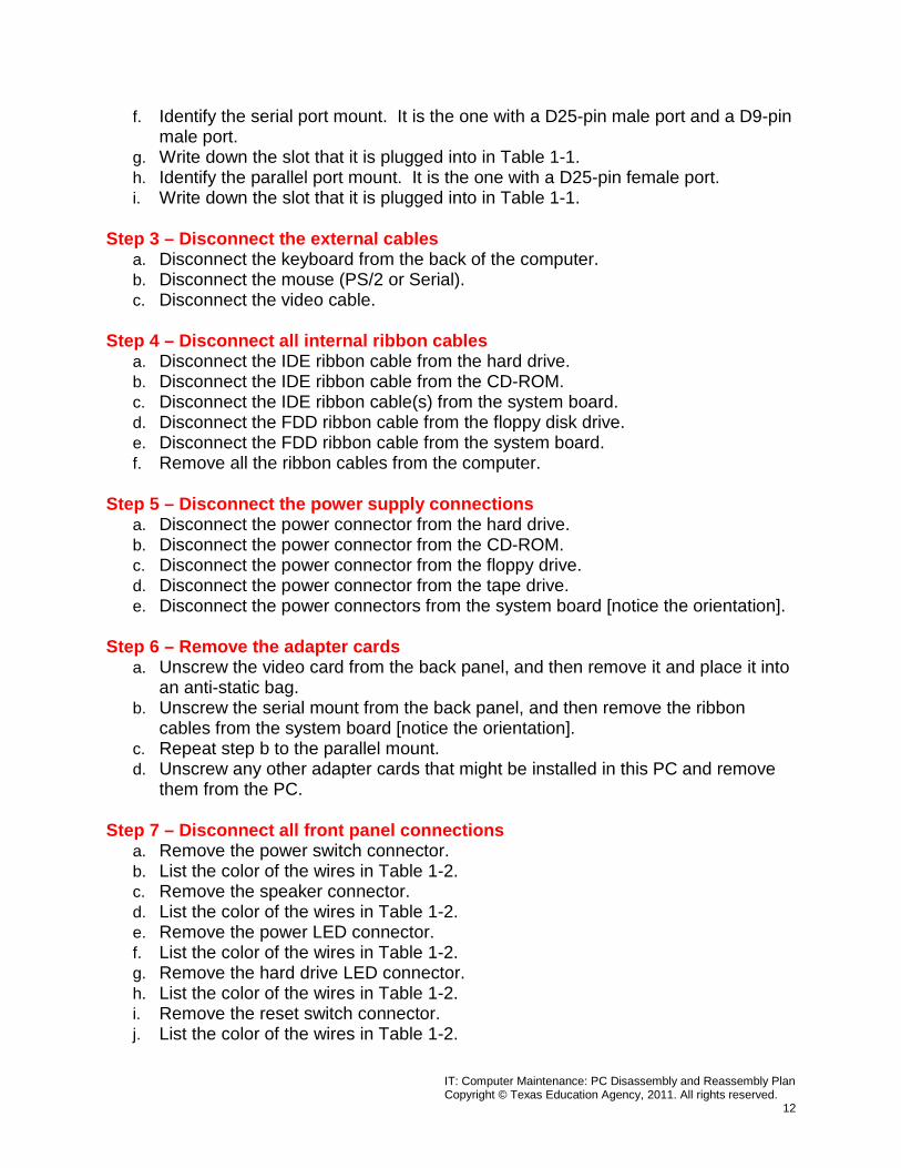
f. Identify the serial port mount. It is the one with a D25-pin male port and a D9-pin male port.
g. Write down the slot that it is plugged into in Table 1-1. h. Identify the parallel port mount. It is the one with a D25-pin female port. i. Write down the slot that it is plugged into in Table 1-1.
Step 3 – Disconnect the external cables a. Disconnect the keyboard from the back of the computer. b. Disconnect the mouse (PS/2 or Serial). c. Disconnect the video cable.
Step 4 – Disconnect all internal ribbon cables a. Disconnect the IDE ribbon cable from the hard drive. b. Disconnect the IDE ribbon cable from the CD-ROM. c. Disconnect the IDE ribbon cable(s) from the system board. d. Disconnect the FDD ribbon cable from the floppy disk drive. e. Disconnect the FDD ribbon cable from the system board. f. Remove all the ribbon cables from the computer.
Step 5 – Disconnect the power supply connections a. Disconnect the power connector from the hard drive. b. Disconnect the power connector from the CD-ROM. c. Disconnect the power connector from the floppy drive. d. Disconnect the power connector from the tape drive. e. Disconnect the power connectors from the system board [notice the orientation].
Step 6 – Remove the adapter cards a. Unscrew the video card from the back panel, and then remove it and place it into
an anti-static bag. b. Unscrew the serial mount from the back panel, and then remove the ribbon
cables from the system board [notice the orientation]. c. Repeat step b to the parallel mount. d. Unscrew any other adapter cards that might be installed in this PC and remove
them from the PC.
Step 7 – Disconnect all front panel connections a. Remove the power switch connector. b. List the color of the wires in Table 1-2. c. Remove the speaker connector. d. List the color of the wires in Table 1-2. e. Remove the power LED connector. f. List the color of the wires in Table 1-2. g. Remove the hard drive LED connector. h. List the color of the wires in Table 1-2. i. Remove the reset switch connector. j. List the color of the wires in Table 1-2.
IT: Computer Maintenance: PC Disassembly and Reassembly Plan Copyright © Texas Education Agency, 2011. All rights reserved.
13
Step 8 – Remove the drives from the chassis a. Remove the hard drive [notice type of screws used]. b. Remove the CD-ROM drive [notice type of screws used]. c. Remove the floppy drive [notice type of screws used].
Step 9 – Remove the system board mount and the system board a. Remove the screws from the system board mount. b. Pull the system board mount and the system board from the chassis. c. Remove the system board mounting screws from the system board. d. Remove the system board.
Step 10 – Remove the power supply a. Remove the switch mounting screw from the switch mount at the front of the
chassis. b. Remove the four screws from the back of the chassis that hold the power supply
onto the chassis. c. Remove the power supply.
IT: Computer Maintenance: PC Disassembly and Reassembly Plan Copyright © Texas Education Agency, 2011. All rights reserved.
14
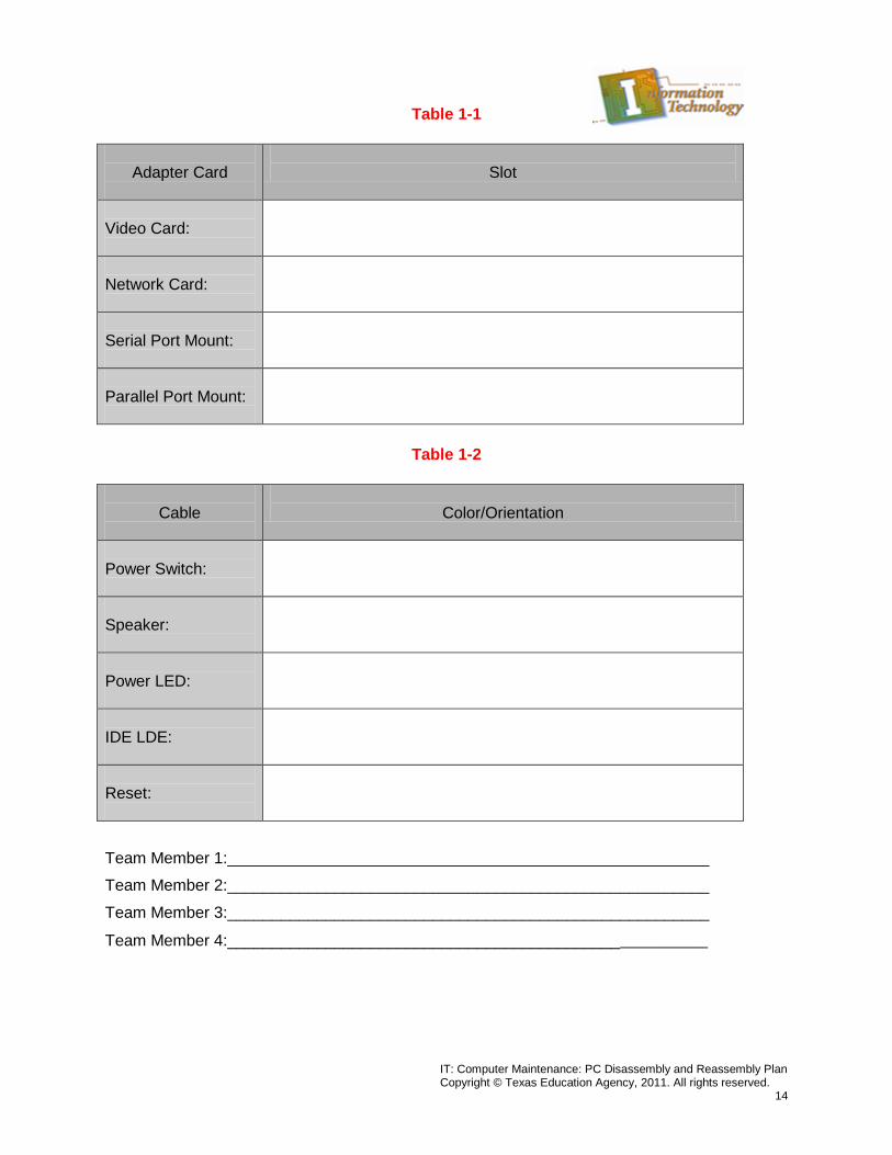
Table 1-1
Adapter Card
Slot
Video Card:
Network Card:
Serial Port Mount:
Parallel Port Mount:
Table 1-2
Cable
Color/Orientation
Power Switch:
Speaker:
Power LED:
IDE LDE:
Reset:
Team Member 1:______________________________________________________
Team Member 2:______________________________________________________
Team Member 3:______________________________________________________
Team Member 4:______________________________________________________
IT: Computer Maintenance: PC Disassembly and Reassembly Plan Copyright © Texas Education Agency, 2011. All rights reserved.
15
LAB 2 – Reassemble a PC
Objectives: • Reassemble a generic PC [disassembled in Lab 1]. • Verify the correct orientation of the interface cables.
Background: In this procedure, you will reassemble the PC that was disassembled in Lab 1. You will go through all the steps of reassembly. After reassembling the PC, you will start the computer to verify that it is operating properly.
Resources: You will work in teams. The following resources will be required:
• PC Tool Kit • Antistatic Wrist Strap • Disassembled personal computer (PC) • Operating system installed on hard drive (MS-DOS, MS Windows
95/98/2000/Millennium)
NOTE: As in Lab 1, this lab assumes an AT-type PC is used. If an ATX-type PC is used some modifications might need to be made in the step-by-step procedures, i.e. the video and input/output ports along with the IDE ports may be located on the motherboard instead of interface cards.
Step 1 – Install the power supply a. Place the power supply back into the chassis. b. Insert the four screws through the back of the chassis; these hold the power supply onto
the chassis. c. Attach the switch mounting screw through the switch mount at front of the chassis.
Step 2 – Attach the system board mount and the system board a. Place the system board on the system board mounts. b. Install the system board mounting screws through the system board. c. Install the system board mount and the system board into the chassis. d. Install the screws through the system board mount.
Step 3 – Attach all the front panel connections [See Table 1-2, Lab 1 if needed] a. Find the speaker connection and connect it to the motherboard where it is labeled
“Speaker.” b. Find the power LED connector and connect it to the motherboard where it is labeled
“Power LED.” c. Find the hard-disk drive LED connector and connect it to the motherboard [or interface
card] where it is labeled “HDD LED.” d. Find the reset switch connector and connect it to the motherboard where it is labeled
“Reset.”
IT: Computer Maintenance: PC Disassembly and Reassembly Plan Copyright © Texas Education Agency, 2011. All rights reserved.
16
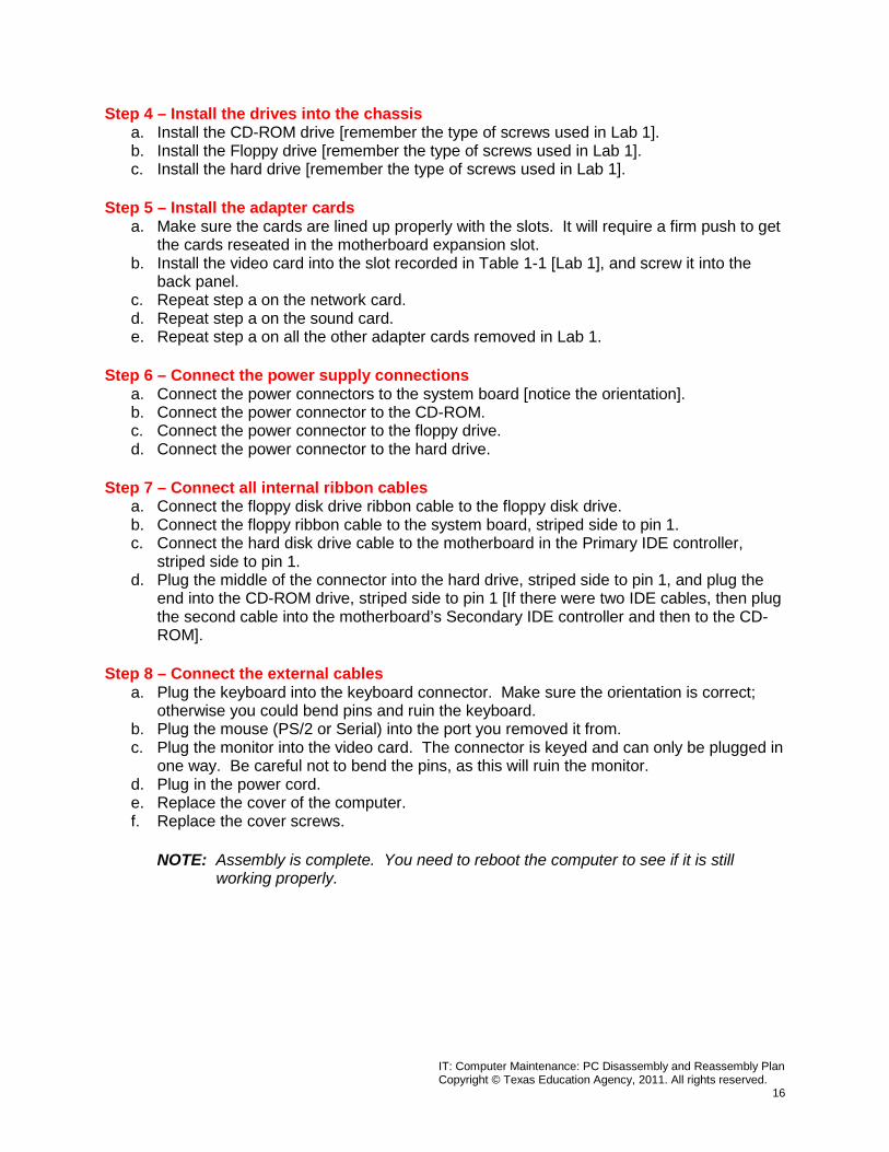
Step 4 – Install the drives into the chassis a. Install the CD-ROM drive [remember the type of screws used in Lab 1]. b. Install the Floppy drive [remember the type of screws used in Lab 1]. c. Install the hard drive [remember the type of screws used in Lab 1].
Step 5 – Install the adapter cards a. Make sure the cards are lined up properly with the slots. It will require a firm push to get
the cards reseated in the motherboard expansion slot. b. Install the video card into the slot recorded in Table 1-1 [Lab 1], and screw it into the
back panel. c. Repeat step a on the network card. d. Repeat step a on the sound card. e. Repeat step a on all the other adapter cards removed in Lab 1.
Step 6 – Connect the power supply connections a. Connect the power connectors to the system board [notice the orientation]. b. Connect the power connector to the CD-ROM. c. Connect the power connector to the floppy drive. d. Connect the power connector to the hard drive.
Step 7 – Connect all internal ribbon cables a. Connect the floppy disk drive ribbon cable to the floppy disk drive. b. Connect the floppy ribbon cable to the system board, striped side to pin 1. c. Connect the hard disk drive cable to the motherboard in the Primary IDE controller,
striped side to pin 1. d. Plug the middle of the connector into the hard drive, striped side to pin 1, and plug the
end into the CD-ROM drive, striped side to pin 1 [If there were two IDE cables, then plug the second cable into the motherboard’s Secondary IDE controller and then to the CD-ROM].
Step 8 – Connect the external cables a. Plug the keyboard into the keyboard connector. Make sure the orientation is correct;
otherwise you could bend pins and ruin the keyboard. b. Plug the mouse (PS/2 or Serial) into the port you removed it from. c. Plug the monitor into the video card. The connector is keyed and can only be plugged in
one way. Be careful not to bend the pins, as this will ruin the monitor. d. Plug in the power cord. e. Replace the cover of the computer. f. Replace the cover screws.
NOTE: Assembly is complete. You need to reboot the computer to see if it is still working properly.

IT: Computer Maintenance: PC Disassembly and Reassembly Plan Copyright © Texas Education Agency, 2011. All rights reserved.
17
Step 9 – Booting up the computer a. Push the power button to turn the computer on. The computer should do a quick
memory test (some numbers will count on the screen). b. The computer will boot up to an MS-DOS screen and should show a “C” prompt that
should look something like this: C:> c. Push the power button to turn the computer off.
Team Member 1:______________________________________________________
Team Member 2:______________________________________________________
Team Member 3:______________________________________________________
Team Member 4:______________________________________________________
IT: Computer Maintenance: PC Disassembly and Reassembly Plan Copyright © Texas Education Agency, 2011. All rights reserved.
18
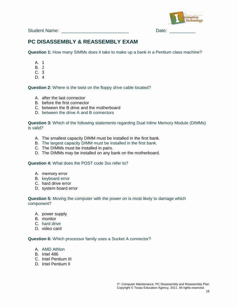
Student Name: __________________________ Date: __________ PC DISASSEMBLY & REASSEMBLY EXAM Question 1: How many SIMMs does it take to make up a bank in a Pentium class machine?
A. 1 B. 2 C. 3 D. 4
Question 2: Where is the twist on the floppy drive cable located?
A. after the last connector B. before the first connector C. between the B drive and the motherboard D. between the drive A and B connectors
Question 3: Which of the following statements regarding Dual Inline Memory Module (DIMMs) is valid?
A. The smallest capacity DIMM must be installed in the first bank. B. The largest capacity DIMM must be installed in the first bank. C. The DIMMs must be installed in pairs. D. The DIMMs may be installed on any bank on the motherboard.
Question 4: What does the POST code 3xx refer to?
A. memory error B. keyboard error C. hard drive error D. system board error
Question 5: Moving the computer with the power on is most likely to damage which component?
A. power supply B. monitor C. hard drive D. video card
Question 6: Which processor family uses a Socket A connector?
A. AMD Athlon B. Intel 486 C. Intel Pentium III D. Intel Pentium II
IT: Computer Maintenance: PC Disassembly and Reassembly Plan Copyright © Texas Education Agency, 2011. All rights reserved.
19
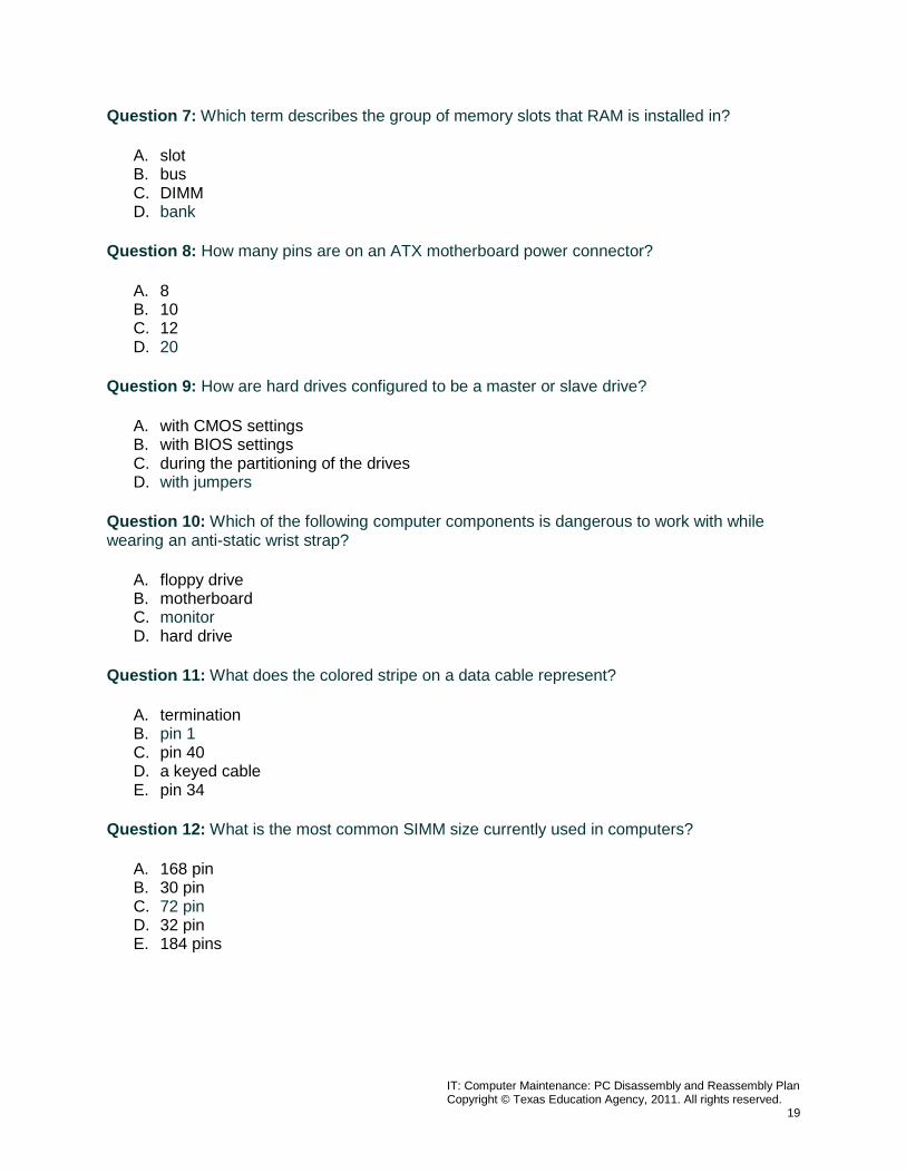
Question 7: Which term describes the group of memory slots that RAM is installed in?
A. slot B. bus C. DIMM D. bank
Question 8: How many pins are on an ATX motherboard power connector?
A. 8 B. 10 C. 12 D. 20
Question 9: How are hard drives configured to be a master or slave drive?
A. with CMOS settings B. with BIOS settings C. during the partitioning of the drives D. with jumpers
Question 10: Which of the following computer components is dangerous to work with while wearing an anti-static wrist strap?
A. floppy drive B. motherboard C. monitor D. hard drive
Question 11: What does the colored stripe on a data cable represent?
A. termination B. pin 1 C. pin 40 D. a keyed cable E. pin 34
Question 12: What is the most common SIMM size currently used in computers?
A. 168 pin B. 30 pin C. 72 pin D. 32 pin E. 184 pins
IT: Computer Maintenance: PC Disassembly and Reassembly Plan Copyright © Texas Education Agency, 2011. All rights reserved.
20
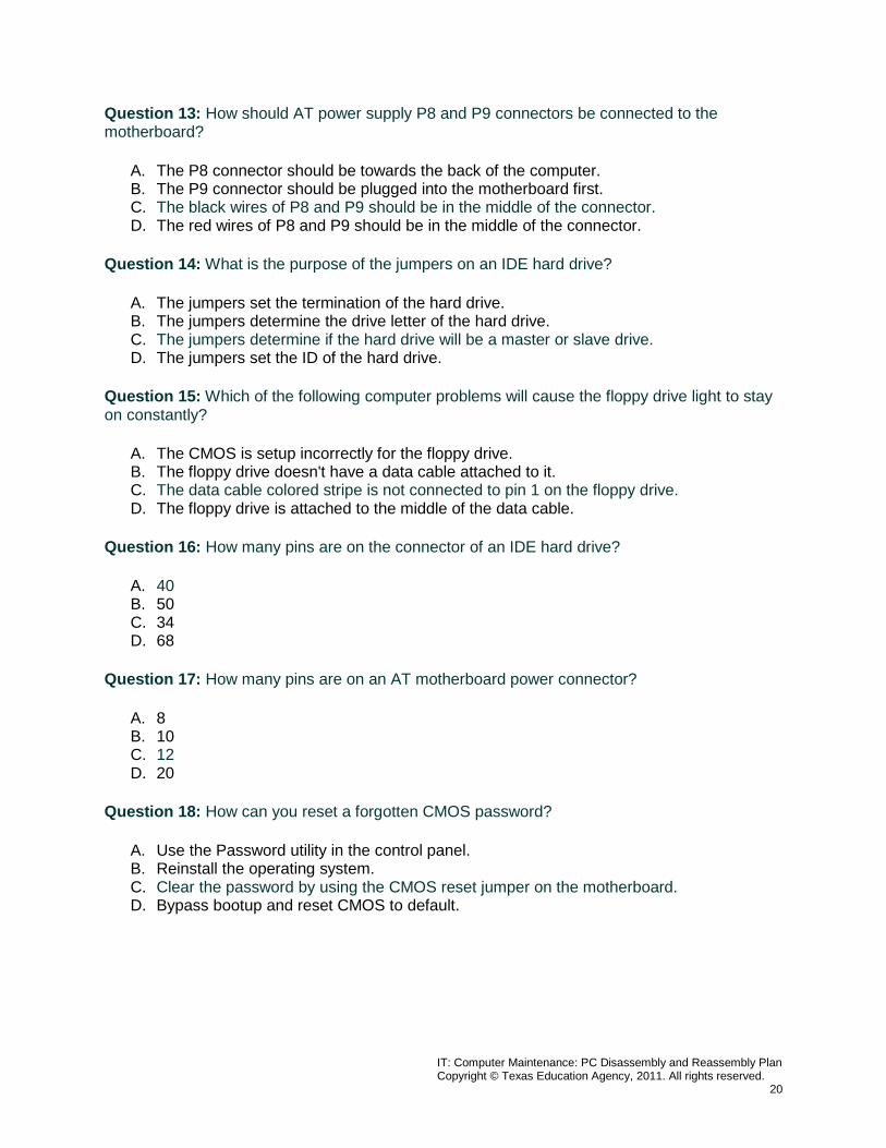
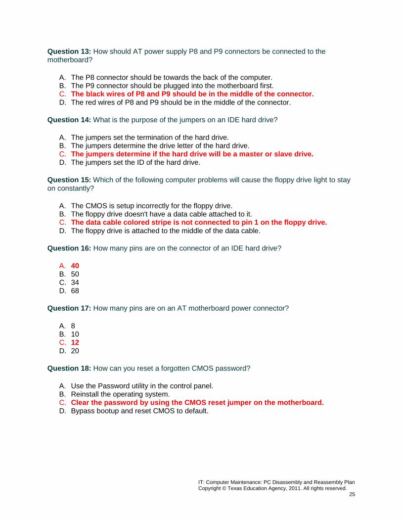
Question 13: How should AT power supply P8 and P9 connectors be connected to the motherboard?
A. The P8 connector should be towards the back of the computer. B. The P9 connector should be plugged into the motherboard first. C. The black wires of P8 and P9 should be in the middle of the connector. D. The red wires of P8 and P9 should be in the middle of the connector.
Question 14: What is the purpose of the jumpers on an IDE hard drive?
A. The jumpers set the termination of the hard drive. B. The jumpers determine the drive letter of the hard drive. C. The jumpers determine if the hard drive will be a master or slave drive. D. The jumpers set the ID of the hard drive.
Question 15: Which of the following computer problems will cause the floppy drive light to stay on constantly?
A. The CMOS is setup incorrectly for the floppy drive. B. The floppy drive doesn't have a data cable attached to it. C. The data cable colored stripe is not connected to pin 1 on the floppy drive. D. The floppy drive is attached to the middle of the data cable.
Question 16: How many pins are on the connector of an IDE hard drive?
A. 40 B. 50 C. 34 D. 68
Question 17: How many pins are on an AT motherboard power connector?
A. 8 B. 10 C. 12 D. 20
Question 18: How can you reset a forgotten CMOS password?
A. Use the Password utility in the control panel. B. Reinstall the operating system. C. Clear the password by using the CMOS reset jumper on the motherboard. D. Bypass bootup and reset CMOS to default.
IT: Computer Maintenance: PC Disassembly and Reassembly Plan Copyright © Texas Education Agency, 2011. All rights reserved.
21
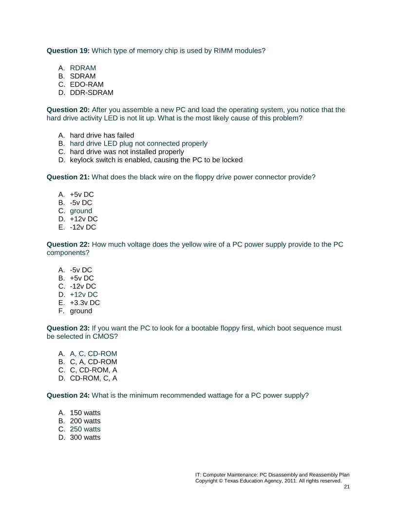
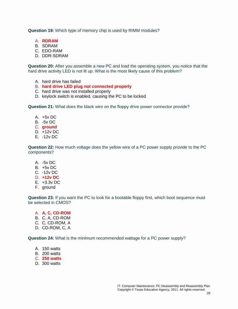
Question 19: Which type of memory chip is used by RIMM modules?
A. RDRAM B. SDRAM C. EDO-RAM D. DDR-SDRAM
Question 20: After you assemble a new PC and load the operating system, you notice that the hard drive activity LED is not lit up. What is the most likely cause of this problem?
A. hard drive has failed B. hard drive LED plug not connected properly C. hard drive was not installed properly D. keylock switch is enabled, causing the PC to be locked
Question 21: What does the black wire on the floppy drive power connector provide?
A. +5v DC B. -5v DC C. ground D. +12v DC E. -12v DC
Question 22: How much voltage does the yellow wire of a PC power supply provide to the PC components?
A. -5v DC B. +5v DC C. -12v DC D. +12v DC E. +3.3v DC F. ground
Question 23: If you want the PC to look for a bootable floppy first, which boot sequence must be selected in CMOS?
A. A, C, CD-ROM B. C, A, CD-ROM C. C, CD-ROM, A D. CD-ROM, C, A
Question 24: What is the minimum recommended wattage for a PC power supply?
A. 150 watts B. 200 watts C. 250 watts D. 300 watts
IT: Computer Maintenance: PC Disassembly and Reassembly Plan Copyright © Texas Education Agency, 2011. All rights reserved.
22
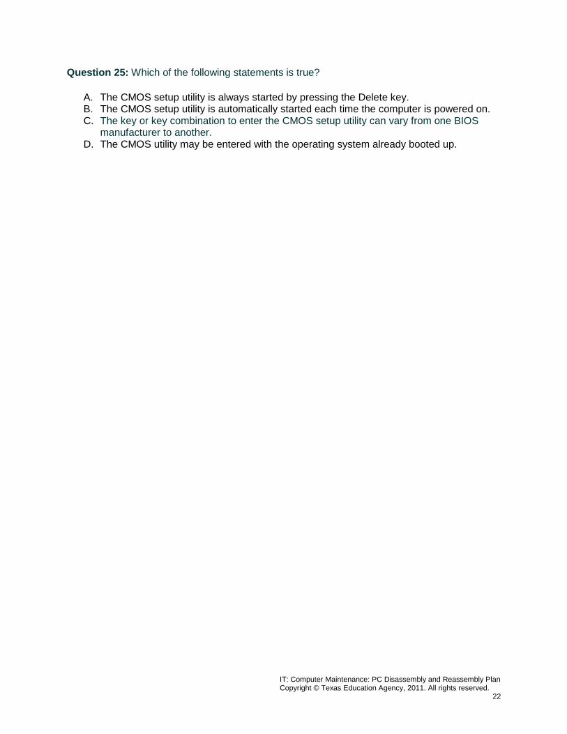
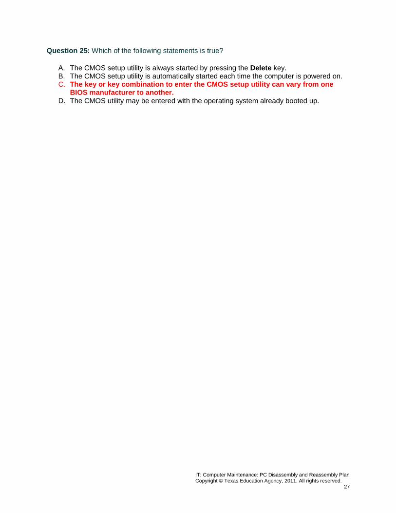
Question 25: Which of the following statements is true?
A. The CMOS setup utility is always started by pressing the Delete key. B. The CMOS setup utility is automatically started each time the computer is powered on. C. The key or key combination to enter the CMOS setup utility can vary from one BIOS
manufacturer to another. D. The CMOS utility may be entered with the operating system already booted up.
IT: Computer Maintenance: PC Disassembly and Reassembly Plan Copyright © Texas Education Agency, 2011. All rights reserved.
23
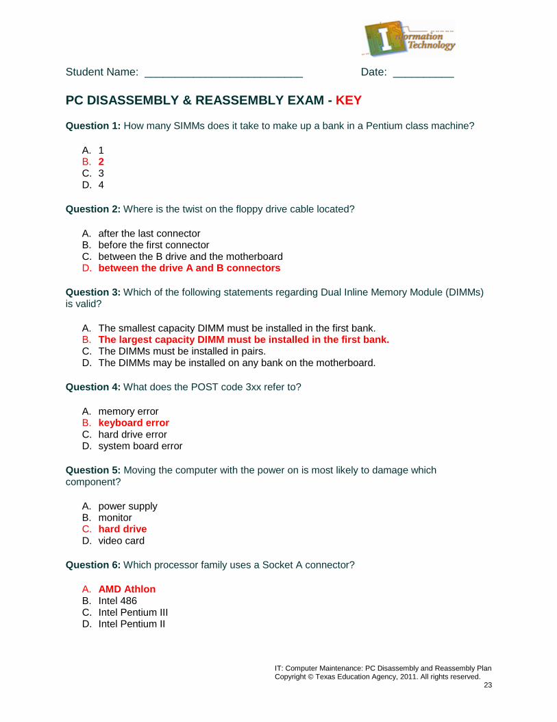
Student Name: __________________________ Date: __________ PC DISASSEMBLY & REASSEMBLY EXAM - KEY Question 1: How many SIMMs does it take to make up a bank in a Pentium class machine?
A. 1 B. 2 C. 3 D. 4
Question 2: Where is the twist on the floppy drive cable located?
A. after the last connector B. before the first connector C. between the B drive and the motherboard D. between the drive A and B connectors
Question 3: Which of the following statements regarding Dual Inline Memory Module (DIMMs) is valid?
A. The smallest capacity DIMM must be installed in the first bank. B. The largest capacity DIMM must be installed in the first bank. C. The DIMMs must be installed in pairs. D. The DIMMs may be installed on any bank on the motherboard.
Question 4: What does the POST code 3xx refer to?
A. memory error B. keyboard error C. hard drive error D. system board error
Question 5: Moving the computer with the power on is most likely to damage which component?
A. power supply B. monitor C. hard drive D. video card
Question 6: Which processor family uses a Socket A connector?
A. AMD Athlon B. Intel 486 C. Intel Pentium III D. Intel Pentium II
IT: Computer Maintenance: PC Disassembly and Reassembly Plan Copyright © Texas Education Agency, 2011. All rights reserved.
24
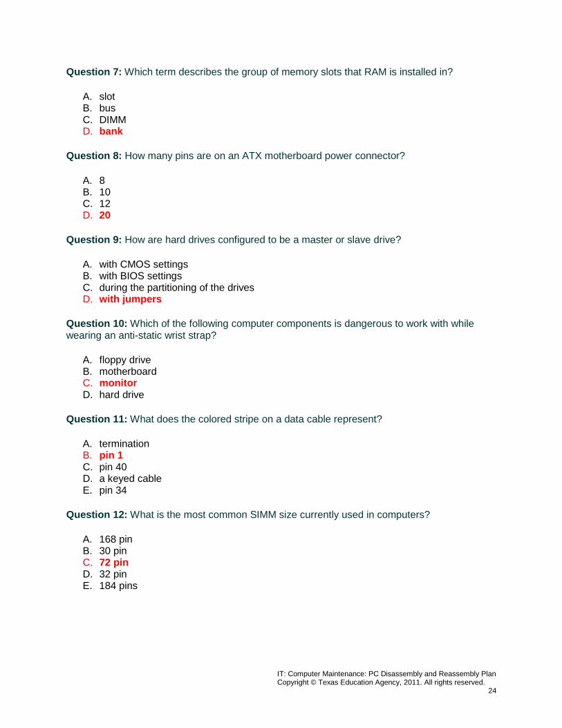
Question 7: Which term describes the group of memory slots that RAM is installed in?
A. slot B. bus C. DIMM D. bank
Question 8: How many pins are on an ATX motherboard power connector?
A. 8 B. 10 C. 12 D. 20
Question 9: How are hard drives configured to be a master or slave drive?
A. with CMOS settings B. with BIOS settings C. during the partitioning of the drives D. with jumpers
Question 10: Which of the following computer components is dangerous to work with while wearing an anti-static wrist strap?
A. floppy drive B. motherboard C. monitor D. hard drive
Question 11: What does the colored stripe on a data cable represent?
A. termination B. pin 1 C. pin 40 D. a keyed cable E. pin 34
Question 12: What is the most common SIMM size currently used in computers?
A. 168 pin B. 30 pin C. 72 pin D. 32 pin E. 184 pins
IT: Computer Maintenance: PC Disassembly and Reassembly Plan Copyright © Texas Education Agency, 2011. All rights reserved.
25
Question 13: How should AT power supply P8 and P9 connectors be connected to the motherboard?
A. The P8 connector should be towards the back of the computer. B. The P9 connector should be plugged into the motherboard first. C. The black wires of P8 and P9 should be in the middle of the connector. D. The red wires of P8 and P9 should be in the middle of the connector.
Question 14: What is the purpose of the jumpers on an IDE hard drive?
A. The jumpers set the termination of the hard drive. B. The jumpers determine the drive letter of the hard drive. C. The jumpers determine if the hard drive will be a master or slave drive. D. The jumpers set the ID of the hard drive.
Question 15: Which of the following computer problems will cause the floppy drive light to stay on constantly?
A. The CMOS is setup incorrectly for the floppy drive. B. The floppy drive doesn't have a data cable attached to it. C. The data cable colored stripe is not connected to pin 1 on the floppy drive. D. The floppy drive is attached to the middle of the data cable.
Question 16: How many pins are on the connector of an IDE hard drive?
A. 40 B. 50 C. 34 D. 68
Question 17: How many pins are on an AT motherboard power connector?
A. 8 B. 10 C. 12 D. 20
Question 18: How can you reset a forgotten CMOS password?
A. Use the Password utility in the control panel. B. Reinstall the operating system. C. Clear the password by using the CMOS reset jumper on the motherboard. D. Bypass bootup and reset CMOS to default.
IT: Computer Maintenance: PC Disassembly and Reassembly Plan Copyright © Texas Education Agency, 2011. All rights reserved.
26
Question 19: Which type of memory chip is used by RIMM modules?
A. RDRAM B. SDRAM C. EDO-RAM D. DDR-SDRAM
Question 20: After you assemble a new PC and load the operating system, you notice that the hard drive activity LED is not lit up. What is the most likely cause of this problem?
A. hard drive has failed B. hard drive LED plug not connected properly C. hard drive was not installed properly D. keylock switch is enabled, causing the PC to be locked
Question 21: What does the black wire on the floppy drive power connector provide?
A. +5v DC B. -5v DC C. ground D. +12v DC E. -12v DC
Question 22: How much voltage does the yellow wire of a PC power supply provide to the PC components?
A. -5v DC B. +5v DC C. -12v DC D. +12v DC E. +3.3v DC F. ground
Question 23: If you want the PC to look for a bootable floppy first, which boot sequence must be selected in CMOS?
A. A, C, CD-ROM B. C, A, CD-ROM C. C, CD-ROM, A D. CD-ROM, C, A
Question 24: What is the minimum recommended wattage for a PC power supply?
A. 150 watts B. 200 watts C. 250 watts D. 300 watts
IT: Computer Maintenance: PC Disassembly and Reassembly Plan Copyright © Texas Education Agency, 2011. All rights reserved.
27
Question 25: Which of the following statements is true?
A. The CMOS setup utility is always started by pressing the Delete key. B. The CMOS setup utility is automatically started each time the computer is powered on. C. The key or key combination to enter the CMOS setup utility can vary from one
BIOS manufacturer to another. D. The CMOS utility may be entered with the operating system already booted up.
IT: Computer Maintenance: PC Disassembly and Reassembly Plan Copyright © Texas Education Agency, 2011. All rights reserved.
28
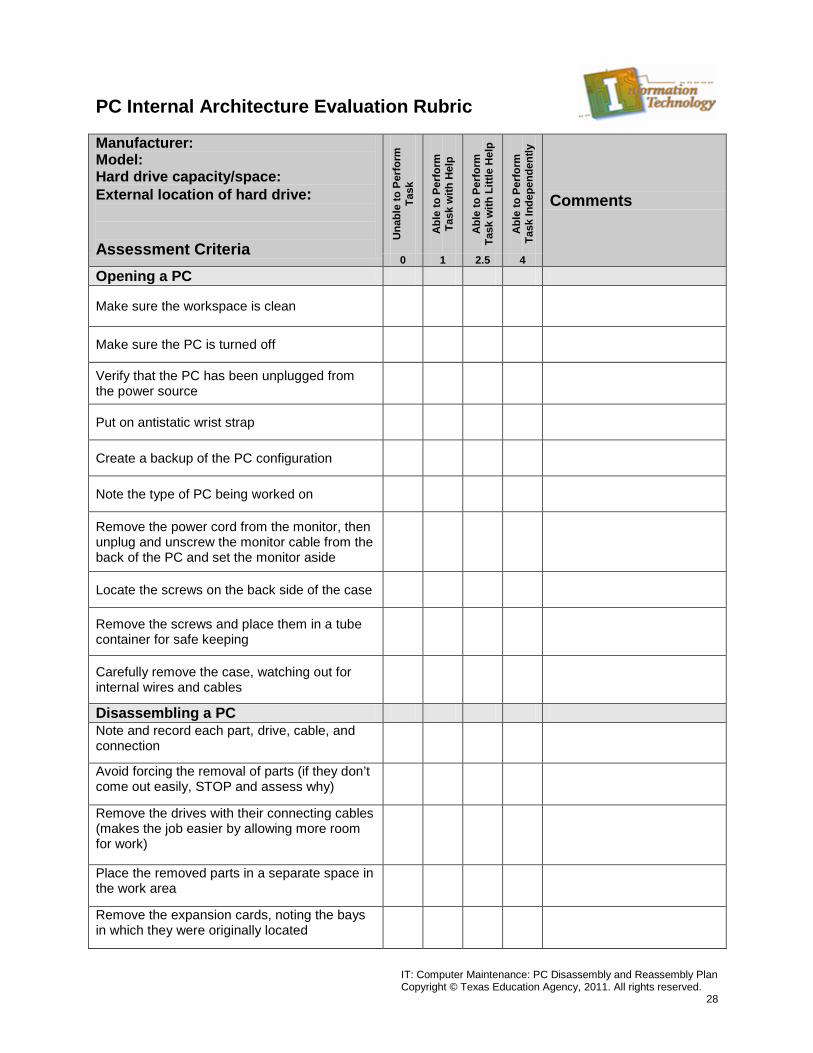
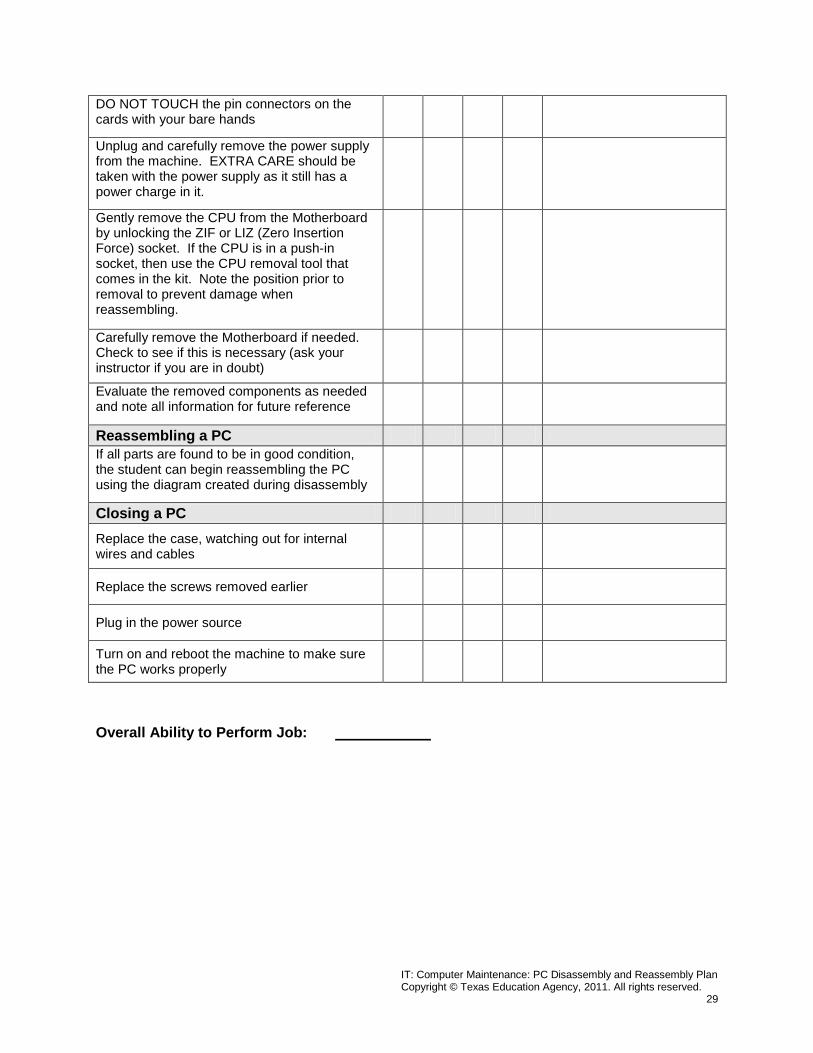
PC Internal Architecture Evaluation Rubric Manufacturer: Model: Hard drive capacity/space: External location of hard drive: Assessment Criteria
Una
ble
to P
erfo
rm
Task
Abl
e to
Per
form
Ta
sk w
ith H
elp
Abl
e to
Per
form
Ta
sk w
ith L
ittle
Hel
p
Abl
e to
Per
form
Ta
sk In
depe
nden
tly
Comments
0 1 2.5 4 Opening a PC
Make sure the workspace is clean
Make sure the PC is turned off
Verify that the PC has been unplugged from the power source
Put on antistatic wrist strap
Create a backup of the PC configuration
Note the type of PC being worked on
Remove the power cord from the monitor, then unplug and unscrew the monitor cable from the back of the PC and set the monitor aside
Locate the screws on the back side of the case
Remove the screws and place them in a tube container for safe keeping
Carefully remove the case, watching out for internal wires and cables
Disassembling a PC Note and record each part, drive, cable, and connection
Avoid forcing the removal of parts (if they don’t come out easily, STOP and assess why)
Remove the drives with their connecting cables (makes the job easier by allowing more room for work)
Place the removed parts in a separate space in the work area
Remove the expansion cards, noting the bays in which they were originally located
IT: Computer Maintenance: PC Disassembly and Reassembly Plan Copyright © Texas Education Agency, 2011. All rights reserved.
29
DO NOT TOUCH the pin connectors on the cards with your bare hands
Unplug and carefully remove the power supply from the machine. EXTRA CARE should be taken with the power supply as it still has a power charge in it.
Gently remove the CPU from the Motherboard by unlocking the ZIF or LIZ (Zero Insertion Force) socket. If the CPU is in a push-in socket, then use the CPU removal tool that comes in the kit. Note the position prior to removal to prevent damage when reassembling.
Carefully remove the Motherboard if needed. Check to see if this is necessary (ask your instructor if you are in doubt)
Evaluate the removed components as needed and note all information for future reference
Reassembling a PC If all parts are found to be in good condition, the student can begin reassembling the PC using the diagram created during disassembly
Closing a PC Replace the case, watching out for internal wires and cables
Replace the screws removed earlier
Plug in the power source
Turn on and reboot the machine to make sure the PC works properly
Overall Ability to Perform Job: