Embed Size (px)
Citation preview
Modeling and Control of Bidirectional
DC DC Converter Fed PMDC Motor
(for HEV Applications)
Thesis submitted in partial fulfillment of the requirements for the degree of
Master of Technology
in
Electrical Engineering(Specialization: Control & Automation)
by
Mahendra Chandra Joshi
Department of Electrical EngineeringNational Institute of Technology Rourkela
Rourkela, Odisha, 769008, IndiaMay 2013
Modeling and Control of Bidirectional
DC DC Converter Fed PMDC Motor
(for HEV Applications)
Dissertation submitted in
in May 2013
to the department of
Electrical Engineering
of
National Institute of Technology Rourkela
in partial fulfillment of the requirements for the degree of
Master of Technology
by
Mahendra Chandra Joshi(Roll 211EE3336 )
under the supervision of
Prof. Susovon Samanta
Department of Electrical EngineeringNational Institute of Technology Rourkela
Rourkela, Odisha, 769008, India
Department of Electrical EngineeringNational Institute of Technology RourkelaRourkela-769008, Odisha, India.
Certificate
This is to certify that the work in the thesis entitled Modeling and Control
of Bidirectional DC DC Converter Fed PMDC Motor (for HEV Ap-
plications) by Mahendra Chandra Joshi is a record of an original research
work carried out by him under my supervision and guidance in partial fulfillment
of the requirements for the award of the degree of Master of Technology with
the specialization of Control & Automation in the department of Electri-
cal Engineering, National Institute of Technology Rourkela. Neither this thesis
nor any part of it has been submitted for any degree or academic award elsewhere.
Place: NIT Rourkela Prof. Susovon SamantaDate: May 2013 Professor, EE Department
NIT Rourkela, Odisha

Acknowledgment
First and Foremost, I would like to express my sincere gratitude towards my su-
pervisior Prof. Susovon Samanta for his advice during my project work. He has
constantly encouraged me to remain focused on achieving my goal. His observa-
tions and comments helped me to establish the overall direction of the research
and to move forward with investigation in depth. He has helped me greatly and
been a source of knowledge.
I extend my thanks to our HOD, Prof. A.K Panda and to all the professors of
the department for their support and encouragement.
I am really thankful to my batchmates especially Raghu, Usha, Vimal, and
Ankush who helped me during my course work and also in writing the thesis .
Also I would like to thanks my all friends particularly Amit, Narendra, Piyush
and Tanmay for their personal and moral support. My sincere thanks to everyone
who has provided me with kind words, a welcome ear, new ideas, useful criticism,
or their invaluable time, I am truly indebted.
I must acknowledge the academic resources that I have got from NIT Rourkela.
I would like to thank administrative and technical staff members of the Depart-
ment who have been kind enough to advise and help in their respective roles.
Last, but not the least, I would like to acknowledge the love, support and
motivation I recieved from my parents and therefore I dedicate this thesis to my
family.
Mahendra Chandra Joshi
211EE3336
Abstract
The present work aims at designing and modelling of a bidirectional DC DC
converter for driving a Permanent Magnet DC (PMDC) motor for Hybrid Electric
Vehicle (HEV) and Electric Bikes (EV) application. Permanent Magnet Brushed
DC (PMBDC) motors and Permanent Magnet Brushless DC (PMBLDC) motors
are the most popular options that are used for the integration of an electric bicycle
and bikes. But despite of the simple controllers and low cost of the PMDC motor
its lower efficiency sets it back in choice in the present scenario as compared to the
BLDC motors. The present design aims at improving the efficiency of the PMDC
motor traction drive system by the incorporation of the bidirectional DC DC con-
verter between the electrical source and the traction motor which in addition to
its primary function of providing the traction energy, also facilitates the energy
regeneration during braking (in the case of HEV and EV) and during the motion
along down the slope(in case of a pedalled electric bicycle).The incorporation of
the regenerative braking can improve the efficiency of the traction drive as much
as 25% and therefore improve the driving range. During motoring operation the
converter operates in the step up mode (boost mode) to provide the energy from
the battery to the traction motor while during regeneration the motor acts as
a generator and the DC DC converter operates in step down mode(buck mode)
to recharge the battery. Half Bridge non-isolated bidirectional DC DC converter
topology has been selected for the present work of study because of the absence of
the transformer which reduces the weight of the system and therefore the size and
the cost of the system considerably reduces. Non isolated half bridge topology is
the appropriate option for the systems requiring high power applications as well
as systems having constraints on their size and weight or both such as spacecraft
applications, HEVs and the electric bicycle. Furthermore the switching losses in
conventional converters can be reduced by using soft switching techniques. Zero
Voltage Resonant Soft Switching (ZVRT) technique has been used for the power
conversion in the present work to reduce the power devices switching losses. ZVRT
switching has been achieved by the use of complimentary gate switching method.
Also the use of the ZVRT techniques requires the discontinuous Conduction Mode
(DCM) of the inductor, which further reduces the inductor size. Although the use
of the DCM increases the ripples, the same can be reduced by the interleaving
technique. Also the parasitic ringing of the voltage across the mosfets whenever
the current reaches zero due to the parasitic capacitances of the devices have
been eliminated with the ZVRT soft switching. The power stage modelling of
the converter fed pmdc motor model has been proposed and the state space aver-
aged equations have been designed for the same. Conventionally the bidirectional
DC DC converters are designed with the voltage source on both the sides, but
the present work proposes the converter power stage directly feeding the PMDC
motor. Hence the additional motor parameters affect the design, selection and
optimization of the various converter parameters values. Thus the power stage
consisting of the voltage source(battery) on one side and the PMDC motor on the
other side turns out to be a fifth order system with five energy elements viz an
inductor and two capacitors of the converter as well as the armature inductor and
the moment of inertia of the motor. With the PMDC motor directly fed by the
converters power stage, the whole systems modelling turns out to be an electrome-
chanical system with multiple variables, and since there is not a wider possibility
of selecting the component values of the various parameters of a PMDC motor
with a specified rating available in the market, all that turns out to fulfil the de-
sign requirements is to judiciously compromise with the converters parameters to
meet the various specifications of the system. The state space averaged model has
been used to determine the various input-output transfer functions of the system.
In the present work, the speed and the regenerative braking of the PMDC motor
has been controlled by the duty cycle of the switches .A unified controller has been
designed and simulated for the control of the both the modes i.e. motoring as well
as regeneration.
Contents
Certificate ii
Acknowledgement iii
Abstract iv
List of Figures vii
Symbols and Abbreviations viii
1 Introduction 2
1.1 Background . . . . . . . . . . . . . . . . . . . . . . . . . . . . . . . 2
1.2 Motivation . . . . . . . . . . . . . . . . . . . . . . . . . . . . . . . . 3
1.3 Contribution of the Thesis . . . . . . . . . . . . . . . . . . . . . . . 3
1.4 Literature Review . . . . . . . . . . . . . . . . . . . . . . . . . . . . 4
1.5 Organization of the Thesis . . . . . . . . . . . . . . . . . . . . . . . 5
2 Bidirectional DC DC Converter Topology and Motor Selection 7
2.1 Bidirectional DC DC Converters . . . . . . . . . . . . . . . . . . . . 7
2.1.1 Non-Isolated Bidirectional DC DC converters . . . . . . . . 10
2.2 Isolated Bidirectional DC DC Converter . . . . . . . . . . . . . . . 15
2.3 Motor selection for HEV propulsion system . . . . . . . . . . . . . . 17
3 Bidirectional DC DC Converter fed PMDC motor 25
3.1 Bidirectional DC DC Converter fed PMDC motor Power Stage . . . 25
3.1.1 Circuit Description . . . . . . . . . . . . . . . . . . . . . . . 25
3.1.2 Circuit specifications . . . . . . . . . . . . . . . . . . . . . . 26
3.1.3 Converter Operation . . . . . . . . . . . . . . . . . . . . . . 26
3.2 Converter’s Parameters Designing . . . . . . . . . . . . . . . . . . . 28
vi
3.2.1 Converter operating in the motoring mode in continuous
conduction mode . . . . . . . . . . . . . . . . . . . . . . . . 28
3.2.2 Boundary between Continuous and Discontinuous Conduc-
tion during Motoring mode . . . . . . . . . . . . . . . . . . 29
3.2.3 Discontinuous Conduction Mode . . . . . . . . . . . . . . . . 30
3.2.4 DCM operation of the Converter . . . . . . . . . . . . . . . 31
3.3 Soft Switching Methods . . . . . . . . . . . . . . . . . . . . . . . . 32
3.3.1 Zero current switching . . . . . . . . . . . . . . . . . . . . . 33
3.3.2 Zero Voltage switching . . . . . . . . . . . . . . . . . . . . . 34
3.4 Parasitic Ringing Due To Parasitic Capacitance . . . . . . . . . . . 35
3.5 Inductance Selection . . . . . . . . . . . . . . . . . . . . . . . . . . 37
4 State Space Modeling and Controller design 42
4.1 Introduction . . . . . . . . . . . . . . . . . . . . . . . . . . . . . . 42
4.2 Model Assumptions . . . . . . . . . . . . . . . . . . . . . . . . . . . 43
4.3 State-space Averaged Model . . . . . . . . . . . . . . . . . . . . . . 44
4.3.1 State-Space Averaging . . . . . . . . . . . . . . . . . . . . . 48
4.3.2 Extracting the Transfer functions . . . . . . . . . . . . . . . 51
4.4 Controller design for speed control of PMDC motor fed by Bidirec-
tional DC DC converter: . . . . . . . . . . . . . . . . . . . . . . . . 52
4.4.1 Conventional Controllers for bidirectional DC DC converters
Using General Purpose Switch . . . . . . . . . . . . . . . . . 53
4.4.2 PID Controller Design for DC Motor Speed Tracking . . . . 58
4.4.3 PID controller . . . . . . . . . . . . . . . . . . . . . . . . . 60
4.4.4 Ziegler-Nichols tuning . . . . . . . . . . . . . . . . . . . . . 61
5 Simulation and Results 65
5.1 Conclusion . . . . . . . . . . . . . . . . . . . . . . . . . . . . . . . . 71
5.2 Future Work . . . . . . . . . . . . . . . . . . . . . . . . . . . . . . . 71
Bibliography 72
List of Figures
2.1 Series hybrid Drive Train employing a bidirectional DC DC converter 8
2.2 (a)Buck Converter and (b)Boost Converter . . . . . . . . . . . . . . 10
2.3 Bidirectional Buck Boost Converters . . . . . . . . . . . . . . . . . 11
2.4 Bidirectional Cascade Buck-Boost Converter . . . . . . . . . . . . . 11
2.5 Bidirectional Cuk Converter . . . . . . . . . . . . . . . . . . . . . . 12
2.6 Non Isolated Half-Bridge Bidirectional DC DC Converter resulting
out of the antiparallel connection of the Buck and Boost converters 12
2.7 Basic Structure of an Isolated Bidirectional DC DC Converter . . . 16
2.8 Dual Bridge Isolated Voltage Fed Bidirectional DC DC Converter . 17
3.1 Bidirectional DC DC converter fed PMDC motor . . . . . . . . . . 25
3.2 Complimentary Gate Switching for ZVRT turn on and Soft Switch-
ing turn off and inductor current . . . . . . . . . . . . . . . . . . . 26
3.3 Inductor current, MOSFET Q1 current and the MOSFET Q2 cur-
rent during motoring operation . . . . . . . . . . . . . . . . . . . . 27
3.4 Inductor current waveform during motoring operation in continuous
conduction mode . . . . . . . . . . . . . . . . . . . . . . . . . . . . 28
3.5 The waveforms of inductor current during motoring mode at the
edge of continuous and discontinuous mode of conduction . . . . . . 29
3.6 Inductor current waveform during discontinuous conduction mode . 31
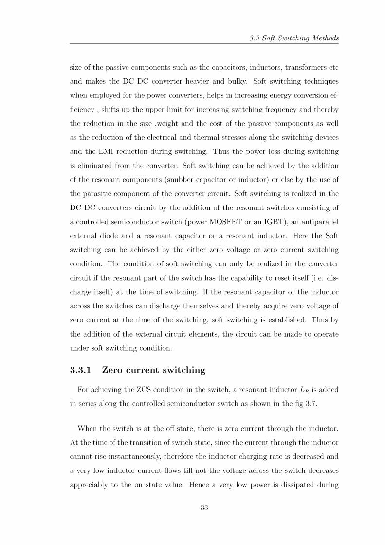
3.7 An elementary resonant switch for achieving ZCS . . . . . . . . . . 34
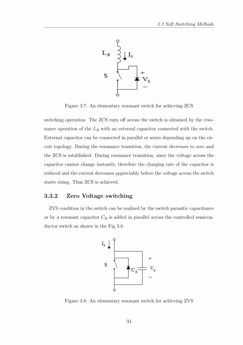
3.8 An elementary resonant switch for achieving ZVS . . . . . . . . . . 34
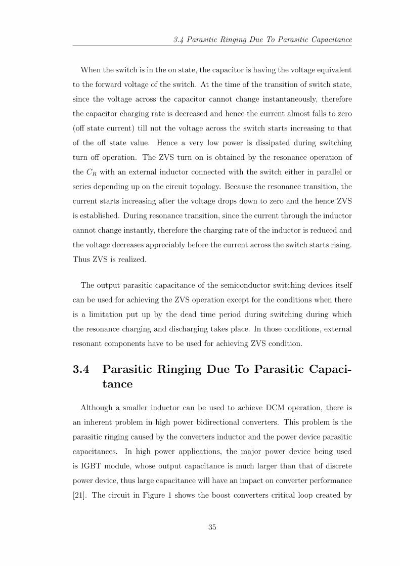
3.9 Parasitic inductance and capacitance in a boost converter . . . . . . 36
3.10 Non-Isolated Bidirectional DC DC Converter Parasitic Capacitances 37
3.11 Inductor Value Optimization for DCM operation . . . . . . . . . . . 40
viii
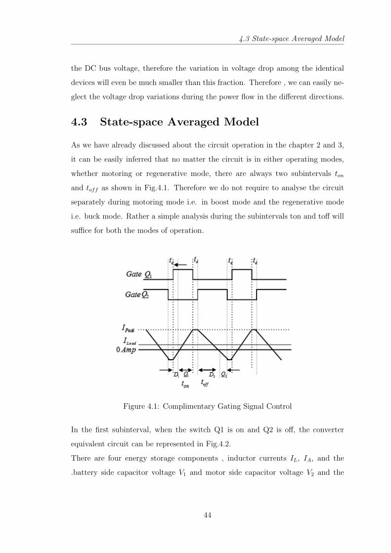
4.1 Complimentary Gating Signal Control . . . . . . . . . . . . . . . . 44
4.2 Equivalent circuit with Q1-on, Q2-off . . . . . . . . . . . . . . . . . 45
4.3 Equivalent circuit with Q1-off, Q2-on . . . . . . . . . . . . . . . . . 46
4.4 shows the bidirectional converter where switches QI and Q2 turn on
and off alternatively through the main switch or the freewheeling
diode according to its operating direction . . . . . . . . . . . . . . . 53
4.5 Power Stage Controlled by the Separate Controller . . . . . . . . . 55
4.6 Power Stage Controlled by a Unified Controller . . . . . . . . . . . 55
4.7 Voltage conversion ratio(15V/25V) Vs Duty cycle for buck switch . 57
4.8 Voltage conversion ratio(25V/15V) Vs Duty cycle for boost switch . 57
4.9 Step response curve for Zeigler Nichols parameters . . . . . . . . . . 61
5.1 MOSFET Voltage Ringing at the zero inductor current without Soft
Turn OFF switching . . . . . . . . . . . . . . . . . . . . . . . . . . 65
Listof Abbreviations
BLDC : Brushless Direct Current
CCM : Continuous Conduction Mode
D : duty ratio
DC : Direct Current
DCM : Discontinuous Conduction Mode
EMI : Electromagnetic Interference
HEV : Hybrid Electric Vehicle
Hz : Hertz
IC : Integrated Circuit
ICE : Internal Combustion Engine
IGBT : Insulated Gate Bipolar Transistor
MOSFET : Metal Oxide Semiconductor Field Effect Transistor
PMBLDC : Permanent Magnet Brushless Direct Current
PMDC : Permanent Magnet Direct Current
PV : Photovoltaic
SOC : State of Charge
ZCS : Zero Current Switching
ZVS : Zero Voltage Switching
ZVRT : Zero Voltage Resonance Transition

Introduction
Chapter 1
Introduction
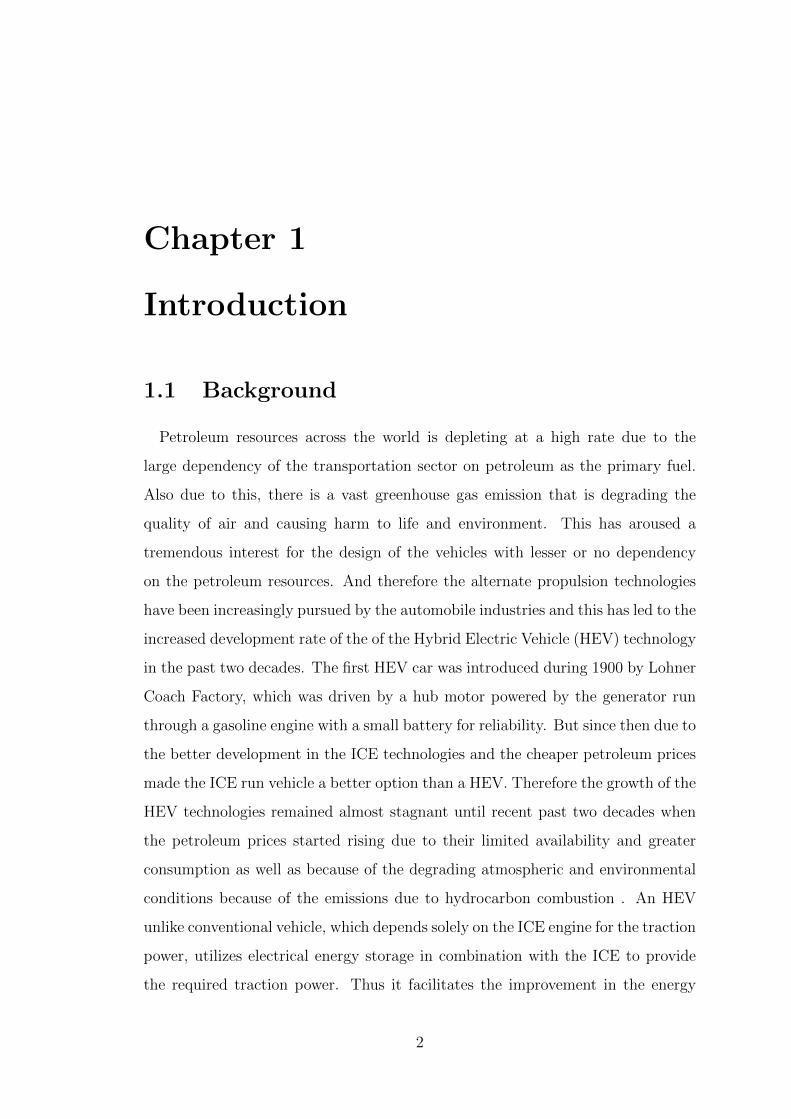
1.1 Background
Petroleum resources across the world is depleting at a high rate due to the
large dependency of the transportation sector on petroleum as the primary fuel.
Also due to this, there is a vast greenhouse gas emission that is degrading the
quality of air and causing harm to life and environment. This has aroused a
tremendous interest for the design of the vehicles with lesser or no dependency
on the petroleum resources. And therefore the alternate propulsion technologies
have been increasingly pursued by the automobile industries and this has led to the
increased development rate of the of the Hybrid Electric Vehicle (HEV) technology
in the past two decades. The first HEV car was introduced during 1900 by Lohner
Coach Factory, which was driven by a hub motor powered by the generator run
through a gasoline engine with a small battery for reliability. But since then due to
the better development in the ICE technologies and the cheaper petroleum prices
made the ICE run vehicle a better option than a HEV. Therefore the growth of the
HEV technologies remained almost stagnant until recent past two decades when
the petroleum prices started rising due to their limited availability and greater
consumption as well as because of the degrading atmospheric and environmental
conditions because of the emissions due to hydrocarbon combustion . An HEV
unlike conventional vehicle, which depends solely on the ICE engine for the traction
power, utilizes electrical energy storage in combination with the ICE to provide
the required traction power. Thus it facilitates the improvement in the energy
2
1.3 Contribution of the Thesis
conversion of the vehicle thereby increasing the efficiency and drivability and at
the same time reducing the emissions. Furthermore the integration of the electrical
storage system also makes the provision for the regeneration during braking which
can further boost up the efficiency of the overall system.
1.2 Motivation
One of the main considerations for the HEV drive train is to improve the ef-
ficiency of the motor drive. This can be done by increasing the voltage level of
the ESS and thereby reducing the high currents and thus the associated losses.
The increase in the voltage level of the ESS can be done by the addition of the
more number of the cells in the battery back of the ESS of the HEV. Although it
increases the voltage level but at the same time it also increases the weight, size
and cost of the system which is obviously not a desirable option for a vehicular
application which has constraints on its size and weight. The other option is to
use a bidirectional DC DC converter. Bidirectional DC DC converters boost up
the voltage level of the electrical storage system to the higher voltage level and
thereby reducing the current level and hence the losses. Also Bidirectional DC
DC converter facilitates the provision for the reverse power flow back into the ESS
during regenerative braking and hence further increasing the efficiency. This two
features of the Bidirectional DC DC converter makes it a better option for power
conversion in the HEV drivetrain thereby reducing overall cost ,size and weight of
the system along with increasing efficiency and achieving regenerative energy .
1.3 Contribution of the Thesis
The primary objective of this work is to design, model and simulate the Bidi-
rectional DC DC converter fed PMDC motor. In accordance with this objective,
the methodology for selecting an appropriate topology of the bidirectional DC DC
converter has been presented and then the power stage of the converter directly
feeding the PMDC motor has been designed to meet the required specifications.
Some of the salient points of this thesis are:
3
1.4 Literature Review
1. Development of converter fed PMDC motor Power Stage Model .
2. Unified Controller during both the modes for the speed control of the PMDC
motor.
3. Controlled regeneration during Braking and downhill motion to charge the
battery.
4. Incorporation of Soft Switching technique to reduce the switching losses in
the motor fed converter.
5. Reduced electromagnetic interference(EMI) due to the elimination of para-
sitic ringing in the converter
6. Converter circuit parameter design procedure.
1.4 Literature Review
With the purpose of improving the efficiency of the drivetrain and to minimize
the dependency on the petroleum fuels two or more sources of the propulsions (in-
cluding ICE) are being employed in the vehicles . This are known as the Hybrid
Electric Vehicles(HEVs). The topological overview of the various hybrid drive
trains and the comparision between them has been presented in [1,2,4]. The role
and the requirement of the power electronics and dc dc converter in the HEV tech-
nology was reviewed and explained in [3,5]. The comparision between the various
non isolated Bidirectional DC DC converters on the basis of their performance has
been done in [7,8,13]. Motor selection and the various drive train issues depending
up on the traction drive requirements and operational performance has been done
in [15, 16]. The power stage design methodology and the ZVRT switching was
introduced in [19]. It also the implemented the DCM operation for the power den-
sity maximization of the converter. The concepts of the soft switching techniques
for the efficiency improvement and the device stress reduction was presented in
the [24,25]. The unified controller for a current mode controlled bidirectional DC
DC converter was presented in [26,28].
4

1.5 Organization of the Thesis
1.5 Organization of the Thesis
The thesis work has been organized as follows:
• Chapter 2: provides an overview of the various bidirectional DC DC con-
verter topologies and the various motors used for the HEV and electric bikes
application.
• Chapter 3:deals with the circuit operation and the design issues. First the
circuit specification has been provided and consequently the design objec-
tives have been set to fulfill the satisfactory operation of the converter.
• Chapter 4: in this chapter, modeling and controller design has been de-
scribed for the converter circuit.
• Chapter 5: presents the simulation results and the analysis along with
future work and conclusion.
5
Bidirectional DC DC ConverterTopology and Motor Selection
Chapter 2
Bidirectional DC DC ConverterTopology and Motor Selection
2.1 Bidirectional DC DC Converters
Bidirectional DC DC converters serves the purpose of stepping up or stepping
down the voltage level between its input and output along with the capability of
power flow in both the directions. Bidirectional DC DC converters have attracted
a great deal of applications in the area of the energy storage systems for Hybrid
Vehicles , Renewable energy storage systems, Uninterruptable power supplies and
Fuel cell storage systems. Traditionally they were used for the motor drives for
the speed control and regenerative braking. Bidirectional DC DC converters are
employed when the DC bus voltage regulation has to be achieved along with
the power flow capability in both the direction. One such example is the power
generation by wind or solar power systems, where there is a large fluctuation in the
generated power because of the the large variation and uncertainty of the energy
supply to the conversion unit (wind turbines & PV panels) by the primary source.
These systems cannot serve as a standalone system for power supply because of
these large fluctuations and therefore these systems are always backed up and
supported by the auxiliary sources which are rechargeable such as battery units or
super capacitors. This sources supplement the main system at the time of energy
deficit to provide the power at regulated level and gets recharged through main
system at the time of surplus power generation or at their lower threshold level
of discharge. Therefore a bidirectional DC DC converter is needed to be able to
7
2.1 Bidirectional DC DC Converters
allow power flow in both the directions at the regulated level.
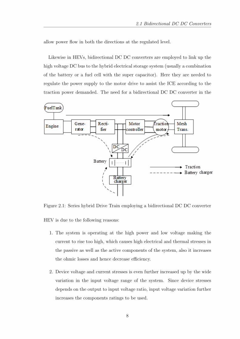
Likewise in HEVs, bidirectional DC DC converters are employed to link up the
high voltage DC bus to the hybrid electrical storage system (usually a combination
of the battery or a fuel cell with the super capacitor). Here they are needed to
regulate the power supply to the motor drive to assist the ICE according to the
traction power demanded. The need for a bidirectional DC DC converter in the
Figure 2.1: Series hybrid Drive Train employing a bidirectional DC DC converter
HEV is due to the following reasons:
1. The system is operating at the high power and low voltage making the
current to rise too high, which causes high electrical and thermal stresses in
the passive as well as the active components of the system, also it increases
the ohmic losses and hence decrease efficiency.
2. Device voltage and current stresses is even further increased up by the wide
variation in the input voltage range of the system. Since device stresses
depends on the output to input voltage ratio, input voltage variation further
increases the components ratings to be used.
8
2.1 Bidirectional DC DC Converters
3. Further along with the above two factors, the parasitic ringing due to the par-
asitic components causes EMI emission and therefore ,the proper shielding
has to be provided. All above three factors makes the converter packaging
bulky, heavy and expensive. Thus there is a need for an efficient DC DC
converter to deal with this issue.
4. To be able to recharge the electrical energy storage system during the re-
generative braking, and hence therefore there should be the provision of
bidirectional power flow.
Some of the requirements for the Bidirectional DC DC converters design for the
HEV applications are as follows :
• High efficiency
• Light weight & compact size
• Lower electromagnetic Interference
• Lower input and output current ripple
• Controlled power flow in spite of wide input voltage variation
Classification of Bidirectional DC DC converter
Basically, bidirectional DC DC converters can be classified into two categories
depending on the Galvanic isolation between the input and output side[6]:
1. Non-Isolated Bidirectional DC DC converters
2. Isolated Bidirectional DC DC converters
9
2.1 Bidirectional DC DC Converters
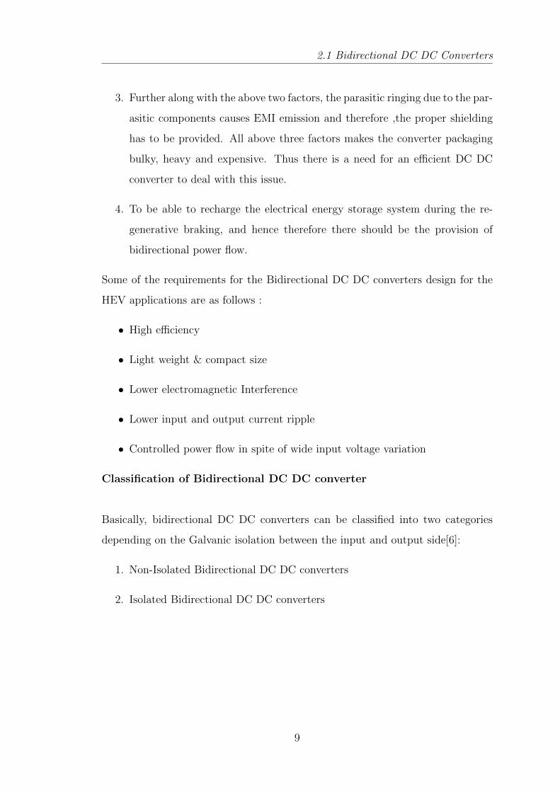
2.1.1 Non-Isolated Bidirectional DC DC converters
Basically a non-isolated bidirectional DC DC converter can be derived from
the unidirectional DC DC converters by enhancing the unidirectional conduction
capability of the conventional converters by the bidirectional conducting switches.
Due to the presence of the diode in the basic buck and boost converter circuits,
they do not have the inherent property of the bidirectional power flow. This
limitation in the conventional Boost and Buck converter circuits can be removed
by introducing a Power Mosfet or an IGBT having an antiparallel diode across
them to form a bidirectional switch and hence allowing current conduction in both
directions for bidirectional power flow in accordance with the controlled switching
operation.
(a) (b)
Figure 2.2: (a)Buck Converter and (b)Boost Converter
Buck Boost Converter
The first bidirectional topology [7] can be directly derived from the conventional
buck boost topology by the introduction of the bidirectional conducting switch as
discussed above. During step up operation Switch Q1 is conducted at the required
duty cycle whereas the switch Q2 is kept off all the time. Similarly during the step
down operation the switch Q2 is made to conduct at required duty cycle whereas
the switch Q1 is always off. Small Dead time is provided during mode transition
in order to avoid the cross conductance through two switches and the converter
output capacitance.
10
2.1 Bidirectional DC DC Converters
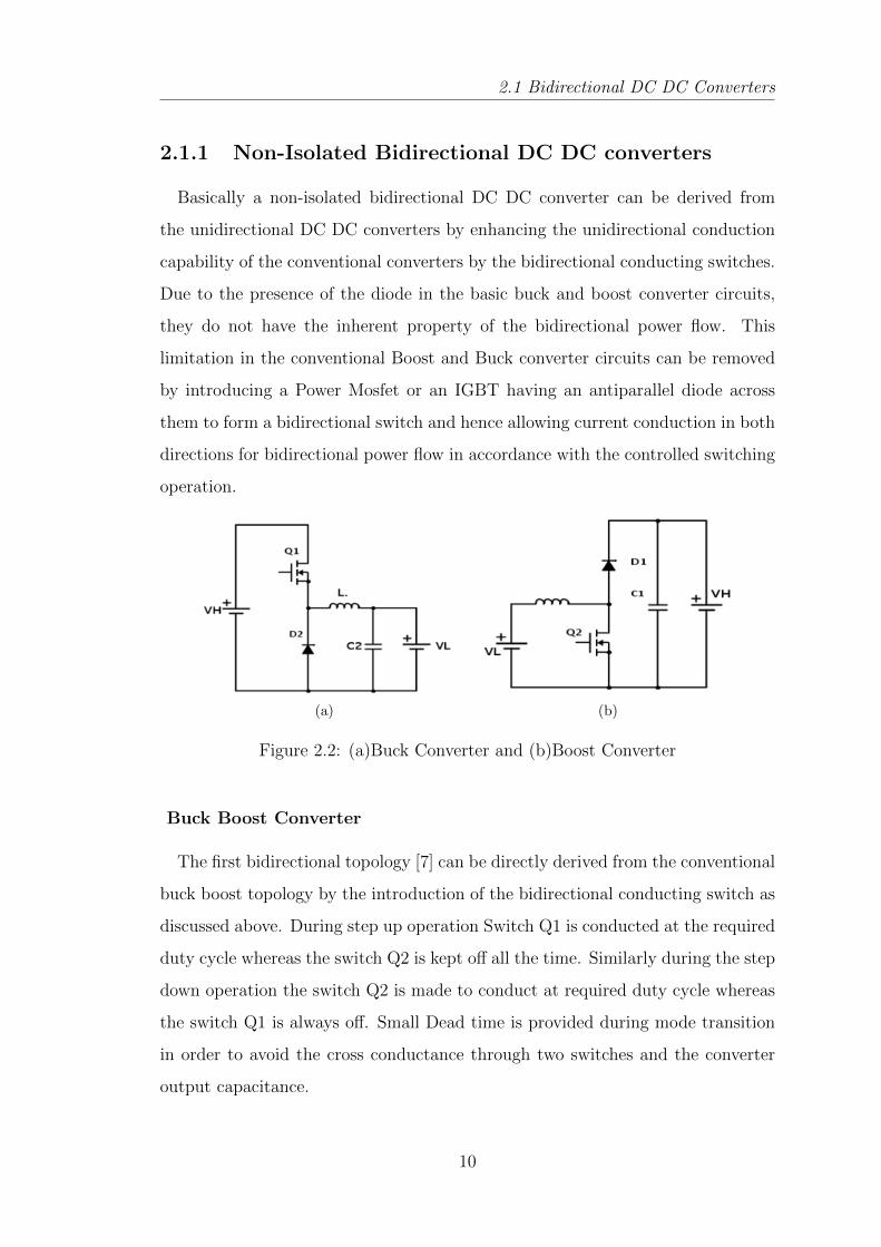
Figure 2.3: Bidirectional Buck Boost Converters
Buck Boost Cascade Converter
The second Bidirectional topology [7] as seen in the fig: 2.4 can be obtained
by cascading the bidirectional buck converter with bidirectional boost converter.
This topology allows the output voltage to be either higher or lower than the input
voltage depending up on the switch combinations used and the direction of the
current. For the step up operation in the forward direction, the switch S1 is always
on and S2 and S4 are always off, whereas the switch S2 is conducted depending
on the duty cycle. During forward step down operation the switch S1 is operated
with the required duty cycle and the switch S2, S3, S4 are always off. Diode D2
and D3 are always reverse biased whereas the D3 is always forward biased. Diode
D4 acts as a freewheeling diode. Similarly in the backward step up operation,
switch S3 is always on whereas the switch S4 is operated with the required duty
cycle with the diode D1 acting as a freewheeling diode.
Figure 2.4: Bidirectional Cascade Buck-Boost Converter
11
2.1 Bidirectional DC DC Converters
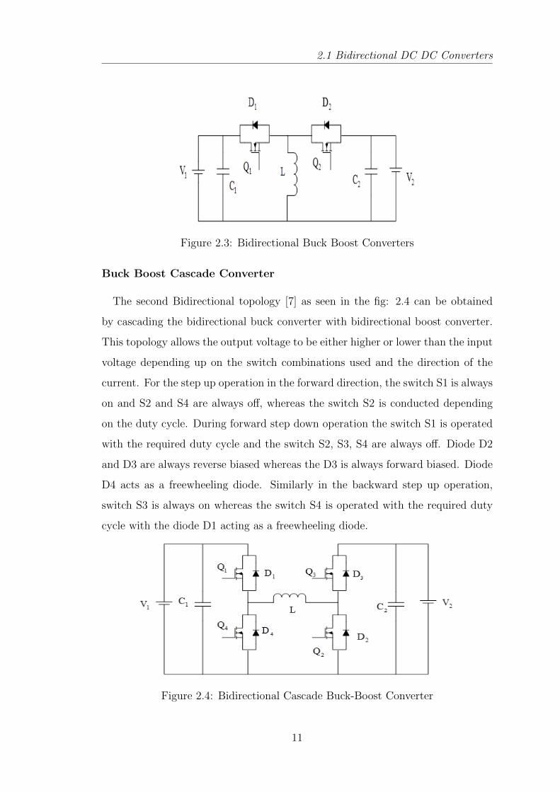
Cuk Converter
The third topology [13] is obtained by replacing the unidirectional switches of
the conventional Cuk converter by the bidirectional switches. The resulting circuit
is as shown in the fig 5. The capacitor C acts as the main storage element whereas
the capacitors C1 and C2 act as the coupling capacitors. It can step up or step
down the input voltage like a buck-boost converter but with inverted polarity.
Figure 2.5: Bidirectional Cuk Converter
Half-Bridge DC DC converter
When the Buck and the boost converters are connected in antiparallel across
each other with the resulting circuit is basically having the same structure as the
fundamental Boost and Buck structure but with the added feature of bidirectional
power flow [8,13]. The below figure shows the basic structure of the Non-Isolated
Half-Bridge Bidirectional DC DC converter.
Figure 2.6: Non Isolated Half-Bridge Bidirectional DC DC Converter resultingout of the antiparallel connection of the Buck and Boost converters
12
2.1 Bidirectional DC DC Converters
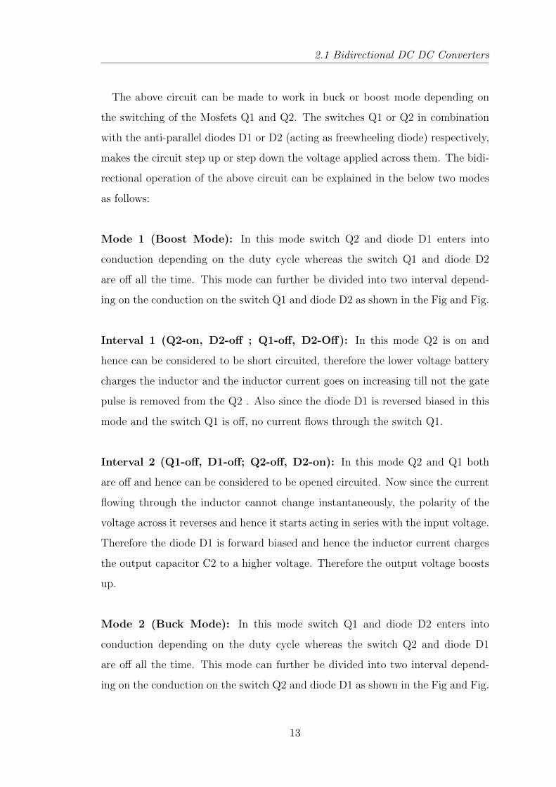
The above circuit can be made to work in buck or boost mode depending on
the switching of the Mosfets Q1 and Q2. The switches Q1 or Q2 in combination
with the anti-parallel diodes D1 or D2 (acting as freewheeling diode) respectively,
makes the circuit step up or step down the voltage applied across them. The bidi-
rectional operation of the above circuit can be explained in the below two modes
as follows:
Mode 1 (Boost Mode): In this mode switch Q2 and diode D1 enters into
conduction depending on the duty cycle whereas the switch Q1 and diode D2
are off all the time. This mode can further be divided into two interval depend-
ing on the conduction on the switch Q1 and diode D2 as shown in the Fig and Fig.
Interval 1 (Q2-on, D2-off ; Q1-off, D2-Off): In this mode Q2 is on and
hence can be considered to be short circuited, therefore the lower voltage battery
charges the inductor and the inductor current goes on increasing till not the gate
pulse is removed from the Q2 . Also since the diode D1 is reversed biased in this
mode and the switch Q1 is off, no current flows through the switch Q1.
Interval 2 (Q1-off, D1-off; Q2-off, D2-on): In this mode Q2 and Q1 both
are off and hence can be considered to be opened circuited. Now since the current
flowing through the inductor cannot change instantaneously, the polarity of the
voltage across it reverses and hence it starts acting in series with the input voltage.
Therefore the diode D1 is forward biased and hence the inductor current charges
the output capacitor C2 to a higher voltage. Therefore the output voltage boosts
up.
Mode 2 (Buck Mode): In this mode switch Q1 and diode D2 enters into
conduction depending on the duty cycle whereas the switch Q2 and diode D1
are off all the time. This mode can further be divided into two interval depend-
ing on the conduction on the switch Q2 and diode D1 as shown in the Fig and Fig.
13
2.1 Bidirectional DC DC Converters
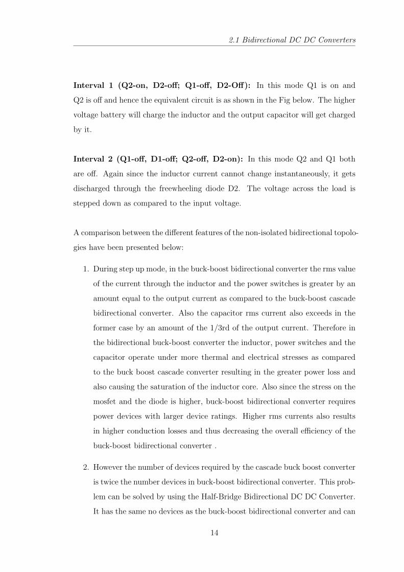
Interval 1 (Q2-on, D2-off; Q1-off, D2-Off): In this mode Q1 is on and
Q2 is off and hence the equivalent circuit is as shown in the Fig below. The higher
voltage battery will charge the inductor and the output capacitor will get charged
by it.
Interval 2 (Q1-off, D1-off; Q2-off, D2-on): In this mode Q2 and Q1 both
are off. Again since the inductor current cannot change instantaneously, it gets
discharged through the freewheeling diode D2. The voltage across the load is
stepped down as compared to the input voltage.
A comparison between the different features of the non-isolated bidirectional topolo-
gies have been presented below:
1. During step up mode, in the buck-boost bidirectional converter the rms value
of the current through the inductor and the power switches is greater by an
amount equal to the output current as compared to the buck-boost cascade
bidirectional converter. Also the capacitor rms current also exceeds in the
former case by an amount of the 1/3rd of the output current. Therefore in
the bidirectional buck-boost converter the inductor, power switches and the
capacitor operate under more thermal and electrical stresses as compared
to the buck boost cascade converter resulting in the greater power loss and
also causing the saturation of the inductor core. Also since the stress on the
mosfet and the diode is higher, buck-boost bidirectional converter requires
power devices with larger device ratings. Higher rms currents also results
in higher conduction losses and thus decreasing the overall efficiency of the
buck-boost bidirectional converter .
2. However the number of devices required by the cascade buck boost converter
is twice the number devices in buck-boost bidirectional converter. This prob-
lem can be solved by using the Half-Bridge Bidirectional DC DC Converter.
It has the same no devices as the buck-boost bidirectional converter and can
14
2.2 Isolated Bidirectional DC DC Converter
be employed instead of the buck-boost cascade bidirectional converter for
the applications that require the boost operation only in one direction and
the buck in the other.
3. The main advantages of the half bridge bidirectional converter as compared
to the bidirectional Cuk converter is that it only requires one inductor instead
of two and that too half the value of latter as well as the power switches
ratings required for the half bridge bidirectional converter is much lower
as compared to the Cuk converter. Also the efficiency of the half bridge
converter is higher than the Cuk converter because of the lower inductor
current and therefore lower conduction as well as lower switching losses.
2.2 Isolated Bidirectional DC DC Converter
These converters can regulate a wide range of power from few watts to hundreds
of kilowatts. Galvanic isolation is required in certain applications demanding Per-
sonnel safety, noise reduction as well as proper operation of protection systems.
Also certain systems require voltage matching between the different stages for the
proper design and the optimization of different stages. Generally Voltage match-
ing and Galvanic isolation is achieved by the transformer in a power electronic
circuitry. This necessitates the requirement of the ac link for the energy transfer.
Thus the system complexity grows up with the incorporation of all this features.
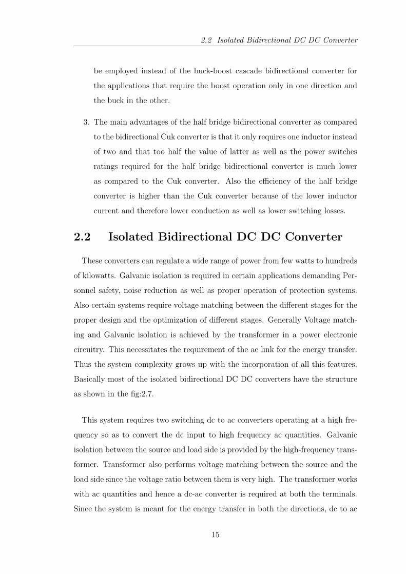
Basically most of the isolated bidirectional DC DC converters have the structure
as shown in the fig:2.7.
This system requires two switching dc to ac converters operating at a high fre-
quency so as to convert the dc input to high frequency ac quantities. Galvanic
isolation between the source and load side is provided by the high-frequency trans-
former. Transformer also performs voltage matching between the source and the
load side since the voltage ratio between them is very high. The transformer works
with ac quantities and hence a dc-ac converter is required at both the terminals.
Since the system is meant for the energy transfer in both the directions, dc to ac
15
2.2 Isolated Bidirectional DC DC Converter
Figure 2.7: Basic Structure of an Isolated Bidirectional DC DC Converter
converters employed must have the capability of bidirectional power flow. This
converters also like the non-isolated bidirectional DC DC converters works in two
modes of operation i.e. in buck or boost.
Isolated bidirectional DC DC converters can be broadly classified into two cat-
egories on the basis of their configuration:
• A current fed isolated bidirectional DC DC converter has an inductor at its
terminals which acts like a current source like a conventional boost converter
with an inductor at the input terminals.
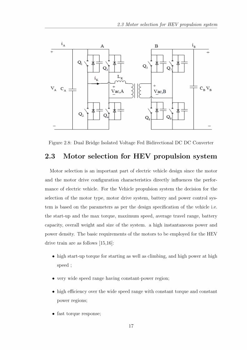
• A voltage fed isolated bidirectional DC DC converter as shown in the fig.2.8
has a capacitor at its terminals which acts like a voltage source like a con-
ventional buck converter with a capacitor at its input terminals.
Since the isolated bidirectional DC DC are having more complex structure, are
more bulky, costlier and heavier than the non-isolated bidirectional DC DC con-
verters due to the presence of the transformer, they are usually unfit for the HEV
application. Also the overall efficiency of the non-isolated bidirectional convert-
ers are more as compared to the isolated bidirectional converters. Therefore the
Non-Isolated Half Bridge Bidirectional DC-DC converter is selected for the present
design.
16
2.3 Motor selection for HEV propulsion system
Figure 2.8: Dual Bridge Isolated Voltage Fed Bidirectional DC DC Converter
2.3 Motor selection for HEV propulsion system
Motor selection is an important part of electric vehicle design since the motor
and the motor drive configuration characteristics directly influences the perfor-
mance of electric vehicle. For the Vehicle propulsion system the decision for the
selection of the motor type, motor drive system, battery and power control sys-
tem is based on the parameters as per the design specification of the vehicle i.e.
the start-up and the max torque, maximum speed, average travel range, battery
capacity, overall weight and size of the system. a high instantaneous power and
power density. The basic requirements of the motors to be employed for the HEV
drive train are as follows [15,16]:
• high start-up torque for starting as well as climbing, and high power at high
speed ;
• very wide speed range having constant-power region;
• high efficiency over the wide speed range with constant torque and constant
power regions;
• fast torque response;
17
2.3 Motor selection for HEV propulsion system
• high efficiency for regenerative braking;
• downsizing, weight reduction, and lower moment of inertia;
• high reliability and robustness for various vehicle operating conditions;
• reasonable cost;
• fault tolerance;
Fundamentally the motors used in hybrid electric vehicles are the same as those
used for other applications except some minor modifications where the motors has
to be directly used as the hub of the wheel, for e.g. generally BLDC motor are
used as the hub motors. Because of the electric motors in hybrid electric drive,
the torque generation is very fast and accurate. Below is the brief description of
the some of the motors used in the Hybrid Electric Vehicle drive:
Brushed DC Motor
DC motor generally has electrical windings in the rotor and the stator is com-
posed of the permanent magnet or electrical windings that act as electromagnets.
The speed torque characteristics of DC motor matches the traction requirements
of a vehicle, therefore they remain an attractive option. The torque is maximum
at the low speed and it gradually decreases as the speed increases. Therefore
it can provide good starting torque. Also the controllers for the DC motors are
simpler and inexpensive. But it has a bulky construction and due to the brushed
commutation, it requires periodic maintenance. At higher speeds, brush friction
gets increased, and therefore the useful torque decreases. Also the power rating
of the motor gets limited by the heat produced by the armature. This heat is
dissipated in the air gap and thus increases the temperature in the air gap and
therefore it limits the motor power and motors output frame. This is the main
disadvantage of the DC motor. Rotor inertia of the DC motor is also higher which
limits its dynamic characteristics.
18
2.3 Motor selection for HEV propulsion system
Brushless Direct Current Motor (BLDC)
BLDC motor is an AC motor. It is also known as permanent magnet syn-
chronous motor, electronically commutated motor etc. Since the armature has no
brushes for commutation, it is called Brushless DC Motor. Commutation in BLDC
motor is electronically achieved based on Hall position sensors. Few limitations of
brushed motors is overcome by brushless motors, i.e. they have higher efficiencies
and reduced mechanical wear and tear of the commutator assembly. Although
these motors also has the parallel disadvantages that they are more expensive,
less rugged, higher complexity, and expensive control electronics. Generally in a
brushless motor the rotor is made up of the permanent magnets instead of the
electrical windings like in a DC motor, and a fixed armature, and therefore the
problem of connecting the current supply to the moving armature gets eliminated.
Commutation is achieved by an electronic controller instead of a brush commu-
tator which continuously switches the phase of the supply to the winding so the
motor keeps rotating. Since no electrical windings is present on the rotor, there-
fore the centrifugal forces due to rotation does not acts on them and also since as
they as are encased in the motor housing, the heat generated can be dissipated
by the conduction through the main assembly and hence no air flow is required
to cool the motor. Therefore the motors internal part can be completely enclosed
and thus can be protected against foreign matters and dust.
Advantages of the BLDC motor over the DC motor are as follows:
• torque per weight and more torque per watt i.e. increase in efficiency,
• increased reliability,
• longer lifetime and no maintenance since no brush and therefore no commu-
tator erosion,
• elimination of ionizing sparks from the commutator, and therefore the re-
19
2.3 Motor selection for HEV propulsion system
duction of electromagnetic interference (EMI)
• reduced noise
Disadvantages:
• The maximum power rating of the BLDC motor is limited mainly by the
heat; since excessive heat weakens the permanent magnets and damages the
windings insulation.
• It has higher cost because of the complex electronic speed controllers.
• It can also be regulated by a comparatively simple controller, such as a
potentiometer using variable resistor. However, this reduces efficiency since
power is wasted in the resistance.
AC Induction Motor
Induction motors or an asynchronous motors are the most preferred and the po-
tential candidate for the HEVs. Induction motor is an AC motor in which current
is induced by the electromagnetic induction in the rotor winding by the magnetic
field of the stator winding. Therefore they do not require the slip rings or the
commutator brushes to slide on the rotor surface for the transfer of the current.
Rotor windings is made up of the short-circuited loops of conductors and can be
of two types :wound rotor and the squirrel cage type. It has the nonlinear speed
to torque characteristics i.e lower torque at lower speeds. Since both stator and
rotor have windings, the output power to size is quite lower than BLDC motors.
Also the motor runs at a lower speed by an amount equals to slip frequency than
the stator and the slip increases with the load. They are generally more suitable
for the industrial and traction drive purposes. Also,presently the induction mo-
tor drive technology is the most advanced technology among the commutatorless
motor drives.
20
2.3 Motor selection for HEV propulsion system
Advantages:
• reliability,
• low maintenance,
• low cost
• ruggedness, and
• ability to operate in adverse environments.
Disadvantages:
• its efficiency is lower than the PMDC motors due to the presence of the
windings in the both rotor and the stator which increases the copper losses.
• low power factor,
• low inverter usage
Switched Reluctance Motor (SRM)
It is a type of synchronous machine. IN SRM only the stator has electrical wind-
ings whereas the rotor contains no windings or permanent magnets. It consists
of only steel laminations stacked onto a shaft. Both the stator and the rotor are
made up of the irons and are magnetized by the current through the stator coil.
The rotor motion is produced because of the variable reluctance in the air gap
between the stator and the rotor. When a stator winding is energized, it produces
a magnetic field, and hence reluctance torque is produced because of the tendency
of the rotor is to move to its minimum reluctance position. The current in the
stator coil does not need to alternate.
Advantages:
• Low Cost because of simple construction
21
2.3 Motor selection for HEV propulsion system
• It can achieve very high speed as compared to other motors due of the
absence of the conductor windings or permanent magnets on the rotor.
• It is very reliable since each phase of the SRM is physically, magnetically,
and electrically independent from the other motor phases.
Disadvantages:
• It has be to always electronically commutated., it can not run directly from
a DC bus or an AC line.
• The saliency of the stator and rotor which is necessary to produce reluctance
torque, results into strong non-linear magnetic characteristics. This makes
the analysis and the control of the SRMs complicated.
Selection of Motor for the Electric bicycle design
Generally low-cost electric scooters and electric bicycles, PM dc motor and PM
brushless dc (PMBLDC) motors are the most used. Usually, the PMBLDC motor
is used in a direct drive motorization (Hub motors) scheme and is mounted in the
wheel. The simplest control method is based on an inverter with voltage control,
PWM modulation and current limitation. Its optimal operating point is at low
speed and high torque. The PM DC motor drive the wheel through a gear/chain
and therefore due to the gear changing mechanism it may operate satisfactorily at
higher speeds and lower torques. The speed control is achieved by the armature
voltage variation generally by using a chopper. These low-cost structures does not
incorporate any mechanism for regenerative braking control strategy. PM brushed
dc motor drives are used in the lower cost traction systems. It uses a simple PWM
chopper converter and a maximal current limitation without having any current
control. The duty cycle is manually adjusted directly by the throttle which in turn
varies the voltage between the brushes. This is a unidirectional current converter
and it is not possible to implement regenerative breaking. Main advantages of
this system are the cost, robustness, compactness due to possibility of reducing
the motor size by using a gearbox, which allows increasing the output torque.
22
2.3 Motor selection for HEV propulsion system
Typically, brush dc motors operate at high speed, up to 5000 rpm. Usually, it is
a ferrite permanent magnet motor and it has low magnetic performance. Current
loop control can be used for the power assisted system to amplify force applied on
the pedals. The polyphase brushless dc motor produces higher torque by using
high performance permanent magnets as NdFeB. Therefore, it is possible with
them to realize direct-drive system in-wheel and a gearbox can thus be avoided..
The disadvantage is the increase in the complexity of the power converter and the
control method. It is necessary to use a polyphase inverter. Simplified control
strategy supplies each phase with square current to minimize the cost of the sen-
sors, as current or position sensors. The controller generates only one modulation
signal.
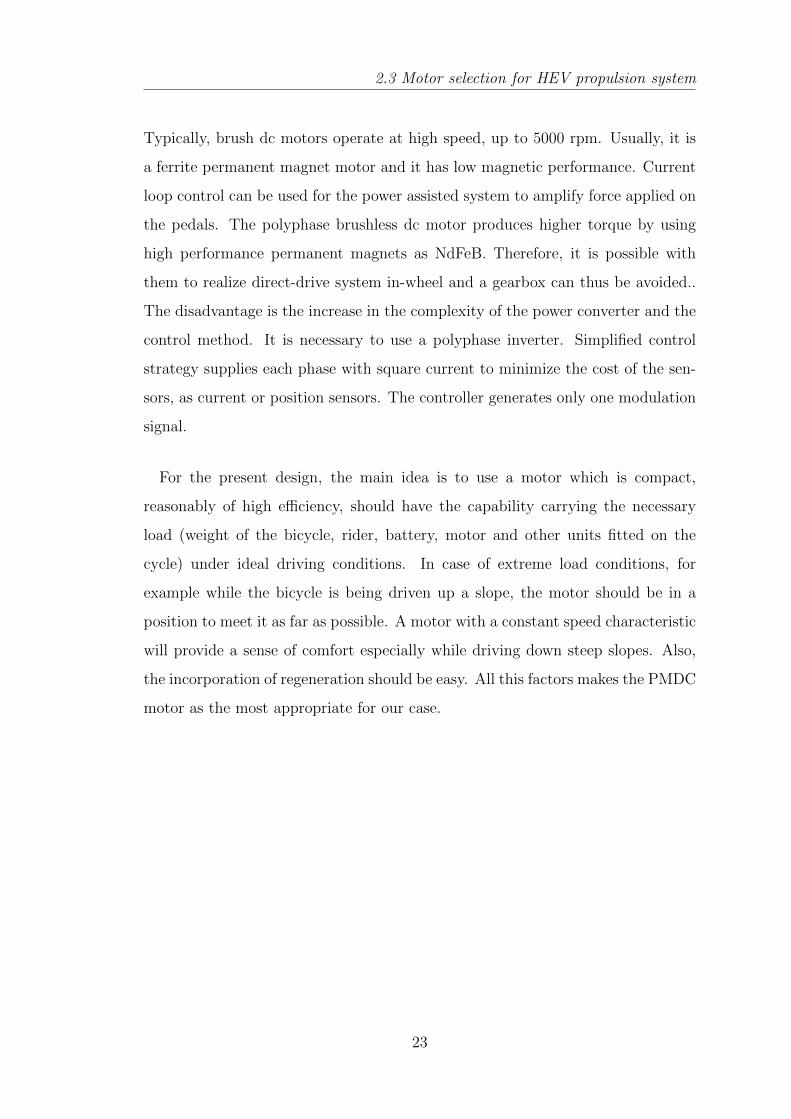
For the present design, the main idea is to use a motor which is compact,
reasonably of high efficiency, should have the capability carrying the necessary
load (weight of the bicycle, rider, battery, motor and other units fitted on the
cycle) under ideal driving conditions. In case of extreme load conditions, for
example while the bicycle is being driven up a slope, the motor should be in a
position to meet it as far as possible. A motor with a constant speed characteristic
will provide a sense of comfort especially while driving down steep slopes. Also,
the incorporation of regeneration should be easy. All this factors makes the PMDC
motor as the most appropriate for our case.
23
Bidirectional DC DCConverter fed PMDC motor
Chapter 3
Bidirectional DC DC Converterfed PMDC motor
3.1 Bidirectional DC DC Converter fed PMDC
motor Power Stage
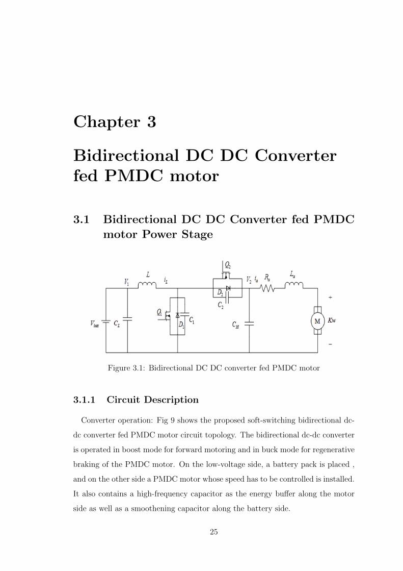
Figure 3.1: Bidirectional DC DC converter fed PMDC motor
3.1.1 Circuit Description
Converter operation: Fig 9 shows the proposed soft-switching bidirectional dc-
dc converter fed PMDC motor circuit topology. The bidirectional dc-dc converter
is operated in boost mode for forward motoring and in buck mode for regenerative
braking of the PMDC motor. On the low-voltage side, a battery pack is placed ,
and on the other side a PMDC motor whose speed has to be controlled is installed.
It also contains a high-frequency capacitor as the energy buffer along the motor
side as well as a smoothening capacitor along the battery side.
25
3.1 Bidirectional DC DC Converter fed PMDC motor Power Stage
3.1.2 Circuit specifications
The design specifications are as follows:
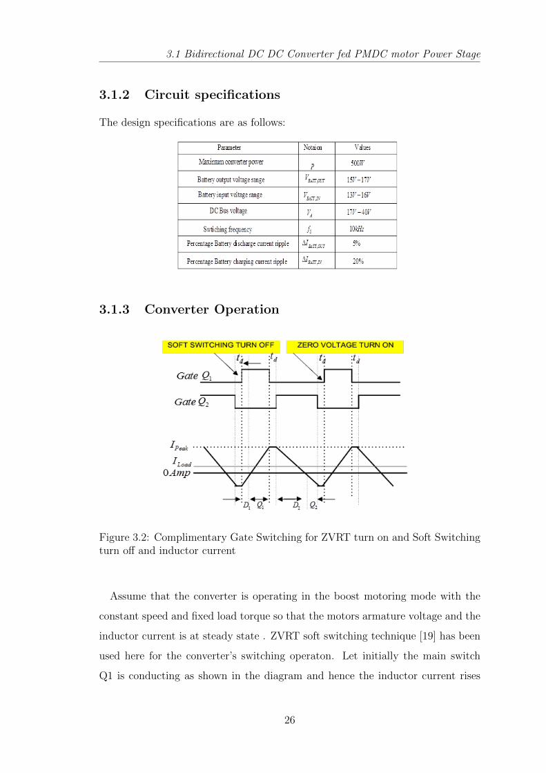
3.1.3 Converter Operation
Figure 3.2: Complimentary Gate Switching for ZVRT turn on and Soft Switchingturn off and inductor current
Assume that the converter is operating in the boost motoring mode with the
constant speed and fixed load torque so that the motors armature voltage and the
inductor current is at steady state . ZVRT soft switching technique [19] has been
used here for the converter’s switching operaton. Let initially the main switch
Q1 is conducting as shown in the diagram and hence the inductor current rises
26
3.1 Bidirectional DC DC Converter fed PMDC motor Power Stage
till not it reaches the dead time when all the devices gets turned off, and there-
fore the inductor current will charge the capacitor C1 and discharge C2. Due to
the presence of the snubber capacitors C1 and C2 , the charging and discharging
rates are reduced .Since the voltage across the capacitors cannot change abruptly,
therefore the switching on and switching off losses are reduced. Now the inductor
current flows through the diode D2 and decreases due to the opposition from volt-
age across capacitor CH till not it becomes zero and reverses its polarity through
Q2, thus the switch Q2 gets on at zero voltage because of the freewheeling current
through D2. Also the diode gets switched off at the zero voltage and therefore
the reverse recovery losses are reduced. Again the negative inductor current goes
though switch Q2 which helps in charging C2 and discharging C1 during the dead
time and after that again the negative current is bypassed through diode D1 till
not it becomes zero and the switch Q1 turns on. Thus the switch Q1 turns on at
Zero Voltage condition.
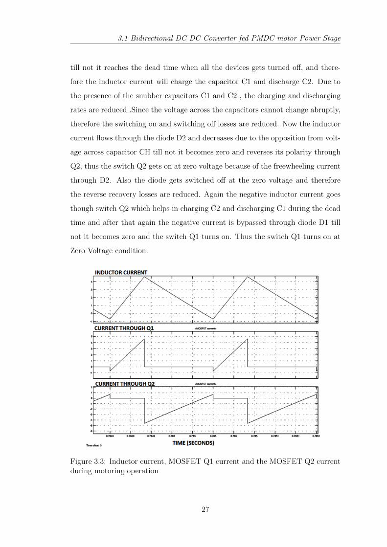
Figure 3.3: Inductor current, MOSFET Q1 current and the MOSFET Q2 currentduring motoring operation
27
3.2 Converter’s Parameters Designing
3.2 Converter’s Parameters Designing
The Bidirectional DC DC converter can operate in the continuous conduction
mode, discontinuous conduction mode as well at the edge of continuous conduction
mode and discontinuous conduction mode. The effect of converter’s operation in
these three conduction modes affects its efficiency and performance in different
ways. Therefore converter’s operation analysis in three modes is necessary before
the design of the circuit parameters.
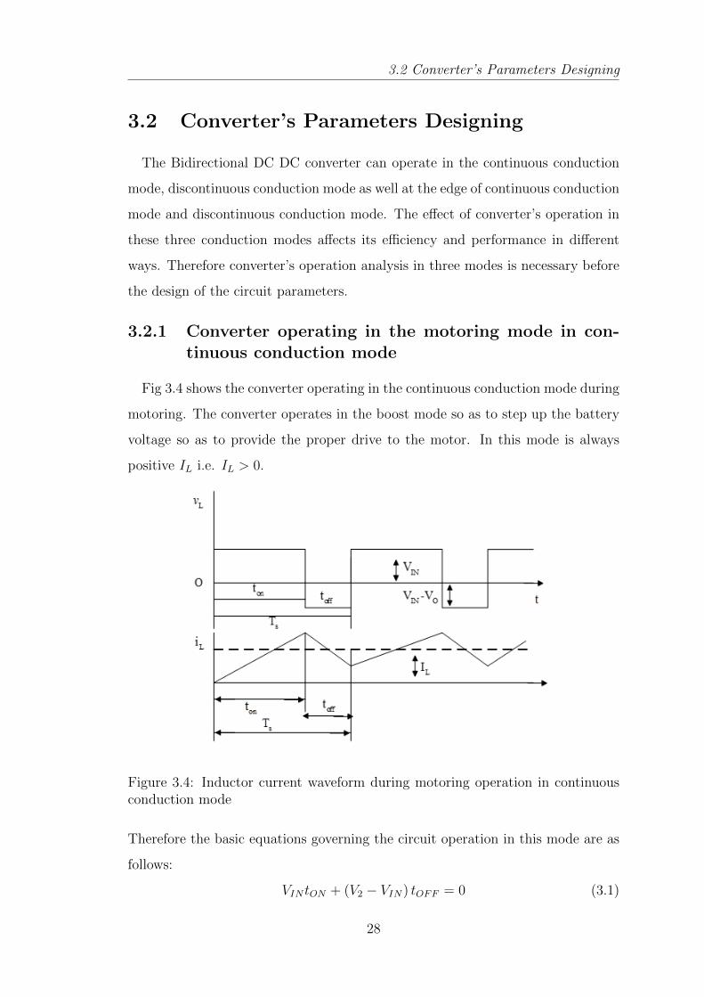
3.2.1 Converter operating in the motoring mode in con-tinuous conduction mode
Fig 3.4 shows the converter operating in the continuous conduction mode during
motoring. The converter operates in the boost mode so as to step up the battery
voltage so as to provide the proper drive to the motor. In this mode is always
positive IL i.e. IL > 0.
Figure 3.4: Inductor current waveform during motoring operation in continuousconduction mode
Therefore the basic equations governing the circuit operation in this mode are as
follows:
VIN tON + (V2 − VIN) tOFF = 0 (3.1)
28
3.2 Converter’s Parameters Designing
Dividing both the sides by the switching time period Ts and rearranging we get,
V2VIN
=1
1−D, (3.2)
Assuming lossless converter operation, the power input should be equal to the
power output, then
Po = PIN (3.3)
V2IA = VINIL (3.4)
Therefore, IA = IL1−D (3.5)
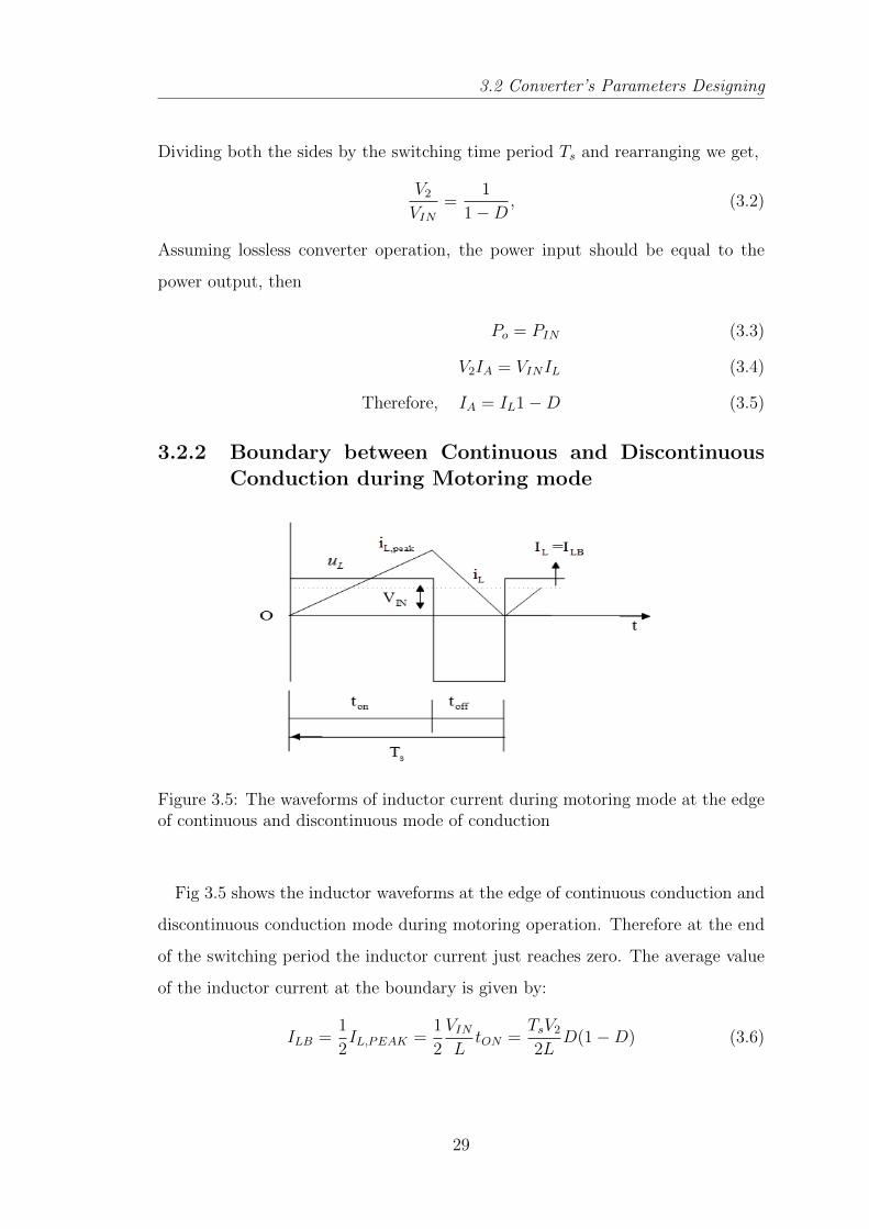
3.2.2 Boundary between Continuous and DiscontinuousConduction during Motoring mode
Figure 3.5: The waveforms of inductor current during motoring mode at the edgeof continuous and discontinuous mode of conduction
Fig 3.5 shows the inductor waveforms at the edge of continuous conduction and
discontinuous conduction mode during motoring operation. Therefore at the end
of the switching period the inductor current just reaches zero. The average value
of the inductor current at the boundary is given by:
ILB =1
2IL,PEAK =
1
2
VINLtON =
TsV22L
D(1−D) (3.6)
29
3.2 Converter’s Parameters Designing
where ILB is the average value of the inductor current at the edge of continuous
and discontinuous mode of conduction.
Considering that during motoring operation(i.e. boost mode), the inductor
current and the input current are the same (I1 = IL),we find that the average
output current during motoring mode at the verge of continuous conduction mode
is:
IA = IL(1−D) (3.7)
IA,AV G =TsV22L
D(1−D)2 (3.8)
From the above equation we find that the ILB reaches the maximum value at
D = 0.5,
ILB,MAX =TsV28L
(3.9)
Also IA has its maximum value at D = 0.33 ,
IAB,MAX =2
27
TsV2L
= 0.74TsV2L
(3.10)
where IAB is the average value of the armature current when the converter is op-
erating at the verge of conduction and disconduction mode.
In terms of their maximum values, ILB,MAX and IAB,MAX can be expressed as:
ILB = 4D(1−D)ILB,MAX (3.11)
IAB =27
4D(1−D)2IAB,MAX (3.12)
3.2.3 Discontinuous Conduction Mode
Since the voltage across the inductor over one time period should be zero, therefore
VINDTs + (VIN − V2)∆1Ts = 0 (3.13)
30
3.2 Converter’s Parameters Designing
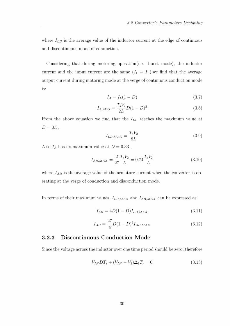
Figure 3.6: Inductor current waveform during discontinuous conduction mode
Thus,V2VIN
=∆1 +D
∆1
andIAIIN
=∆1
∆1 +D(3.14)
From the above Fig 3.6, average battery current(input current) , which is also
equal to the average inductor current therefore,
I1 =VIN2L
DTs(D + ∆1) (3.15)
IA =TsVIN
2LD∆1 (3.16)
If V2 is regulated so as to run the motor at the constant speed and the load is
varying, then the motor current is going to vary so as to so provide the required
torque. We can get the expression of motor current in terms of the duty cycle
with the armature voltage constant as:
D =
[4
27
V2VIN
(V2VIN− 1
)IA
IA,MAX
] 12
(3.17)
3.2.4 DCM operation of the Converter
Bidirectional DC DC converter are generally operated in the continuous conduc-
tion mode (CCM), and hence its design requires a larger valued filter inductor. A
larger inductance can result in an increase in physical size of the inductor, which is
not desirable. This large filter inductor can also slow down the transient response
31
3.3 Soft Switching Methods
of the converter as well as slow down any type of mode transitioning.With the
circuit operating in the discontinuous conduction mode(DCM), the inductor value
considerably reduces . Since the DCM operation facilitates the minimization of
the inductor value and thus making the response faster, therefore the converter
can designed to have a high power density by operating in DCM mode. Another
significant advantage is the zero-turn on loss and therefore low reverse recovery
loss in diode during DCM operation. But, since in the DCM operation the main
switch is switched off at double the value of the load current, therefore the losses
during turn off increases. Also because of this , the inductor current exhibits par-
asitic ringing during turning off of the switch since the output capacitance of the
switch in association with the inductor tries to oscillate and hence causes power
dissipation and electrical stresses on the devices. This is the major disadvantage
associated with the DCM operation. The efficiency reduces because of all this
negative effects of the DCM operation. Therefore the soft switching techniques as
well as the remedial measures for the parasitic ringing have to be ensured in the
converter design.
3.3 Soft Switching Methods
If the converter circuit does not have any auxiliary components , then the
switches operates under hard switching operation and this leads to the consid-
erable amount of the power loss and high electrical stress within the switches
during turn on and turn off condition because of very large values of the current
and voltage simultaneously across it. Generally in all the converters operating
under hard switching conditions and particularly in the high power converters,
switching losses puts the major limitation on the increase of the switching fre-
quency which is desired for the reduction in components values and hence the
size cost and the compactness of the converter. Therefore a compromise is made
with the value of the switching frequency in the practically acceptable range so
as to achieve the high efficiency in the converter and at the same time to and
limit its cost. The reduction in the value of the switching frequency increases the
32
3.3 Soft Switching Methods
size of the passive components such as the capacitors, inductors, transformers etc
and makes the DC DC converter heavier and bulky. Soft switching techniques
when employed for the power converters, helps in increasing energy conversion ef-
ficiency , shifts up the upper limit for increasing switching frequency and thereby
the reduction in the size ,weight and the cost of the passive components as well
as the reduction of the electrical and thermal stresses along the switching devices
and the EMI reduction during switching. Thus the power loss during switching
is eliminated from the converter. Soft switching can be achieved by the addition
of the resonant components (snubber capacitor or inductor) or else by the use of
the parasitic component of the converter circuit. Soft switching is realized in the
DC DC converters circuit by the addition of the resonant switches consisting of
a controlled semiconductor switch (power MOSFET or an IGBT), an antiparallel
external diode and a resonant capacitor or a resonant inductor. Here the Soft
switching can be achieved by the either zero voltage or zero current switching
condition. The condition of soft switching can only be realized in the converter
circuit if the resonant part of the switch has the capability to reset itself (i.e. dis-
charge itself) at the time of switching. If the resonant capacitor or the inductor
across the switches can discharge themselves and thereby acquire zero voltage of
zero current at the time of the switching, soft switching is established. Thus by
the addition of the external circuit elements, the circuit can be made to operate
under soft switching condition.
3.3.1 Zero current switching
For achieving the ZCS condition in the switch, a resonant inductor LR is added
in series along the controlled semiconductor switch as shown in the fig 3.7.
When the switch is at the off state, there is zero current through the inductor.
At the time of the transition of switch state, since the current through the inductor
cannot rise instantaneously, therefore the inductor charging rate is decreased and
a very low inductor current flows till not the voltage across the switch decreases
appreciably to the on state value. Hence a very low power is dissipated during
33
3.3 Soft Switching Methods
Figure 3.7: An elementary resonant switch for achieving ZCS
switching operation. The ZCS turn off across the switch is obtained by the reso-
nance operation of the LR with an external capacitor connected with the switch.
External capacitor can be connected in parallel or series depending up on the cir-
cuit topology. During the resonance transition, the current decreases to zero and
the ZCS is established. During resonance transition, since the voltage across the
capacitor cannot change instantly, therefore the charging rate of the capacitor is
reduced and the current decreases appreciably before the voltage across the switch
starts rising. Thus ZCS is achieved.
3.3.2 Zero Voltage switching
ZVS condition in the switch can be realized by the switch parasitic capacitance
or by a resonant capacitor CR is added in parallel across the controlled semicon-
ductor switch as shown in the Fig 3.8.
Figure 3.8: An elementary resonant switch for achieving ZVS
34
3.4 Parasitic Ringing Due To Parasitic Capacitance
When the switch is in the on state, the capacitor is having the voltage equivalent
to the forward voltage of the switch. At the time of the transition of switch state,
since the voltage across the capacitor cannot change instantaneously, therefore
the capacitor charging rate is decreased and hence the current almost falls to zero
(off state current) till not the voltage across the switch starts increasing to that
of the off state value. Hence a very low power is dissipated during switching
turn off operation. The ZVS turn on is obtained by the resonance operation of
the CR with an external inductor connected with the switch either in parallel or
series depending up on the circuit topology. Because the resonance transition, the
current starts increasing after the voltage drops down to zero and the hence ZVS
is established. During resonance transition, since the current through the inductor
cannot change instantly, therefore the charging rate of the inductor is reduced and
the voltage decreases appreciably before the current across the switch starts rising.
Thus ZVS is realized.
The output parasitic capacitance of the semiconductor switching devices itself
can be used for achieving the ZVS operation except for the conditions when there
is a limitation put up by the dead time period during switching during which
the resonance charging and discharging takes place. In those conditions, external
resonant components have to be used for achieving ZVS condition.
3.4 Parasitic Ringing Due To Parasitic Capaci-
tance
Although a smaller inductor can be used to achieve DCM operation, there is
an inherent problem in high power bidirectional converters. This problem is the
parasitic ringing caused by the converters inductor and the power device parasitic
capacitances. In high power applications, the major power device being used
is IGBT module, whose output capacitance is much larger than that of discrete
power device, thus large capacitance will have an impact on converter performance
[21]. The circuit in Figure 1 shows the boost converters critical loop created by
35
3.4 Parasitic Ringing Due To Parasitic Capacitance
the parasitic inductances and capacitances, labelled as LPAR and CPAR reference
designators.
Figure 3.9: Parasitic inductance and capacitance in a boost converter
The node where the two switches and inductor of a switching converter meet
is called the switch node. It is not uncommon for the parasitic inductances and
capacitances to interact and cause voltage oscillations. If the amplitude of this
ringing is above the absolute maximum rated voltage of the low-side switch, it
can be destructive to the switch. In addition, the conducted emissions and/or
electromagnetic interference (EMI) generated by the ringing can cause problems
for any nearby ICs. The device parasitic capacitance tends to ring with the boost
inductor when high frequency voltage is applied to it. The frequency of ringing
and the magnitude of the oscillating current, both are functions of the inductance
and the parasitic capacitance of the device, which are as shown in the equations
below :
fRINGING =1
2π√LC
=1
2π√
2LCPAR
(3.18)
In order to reduce the effect of ringing the power switches and diodes with
minimal parasitic capacitances should be selected. As the converters inductor
36
3.5 Inductance Selection
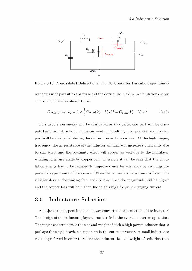
Figure 3.10: Non-Isolated Bidirectional DC DC Converter Parasitic Capacitances
resonates with parasitic capacitance of the device, the maximum circulation energy
can be calculated as shown below:
ECIRCULATION = 2× 1
2CPAR(V2 − VIN)2 = CPAR(V2 − VIN)2 (3.19)
This circulation energy will be dissipated as two parts, one part will be dissi-
pated as proximity effect on inductor winding, resulting in copper loss, and another
part will be dissipated during device turn-on as turn-on loss. At the high ringing
frequency, the ac resistance of the inductor winding will increase significantly due
to skin effect and the proximity effect will appear as well due to the multilayer
winding structure made by copper coil. Therefore it can be seen that the circu-
lation energy has to be reduced to improve converter efficiency by reducing the
parasitic capacitance of the device. When the converters inductance is fixed with
a larger device, the ringing frequency is lower, but the magnitude will be higher
and the copper loss will be higher due to this high frequency ringing current.
3.5 Inductance Selection
A major design aspect in a high power converter is the selection of the inductor.
The design of the inductors plays a crucial role in the overall converter operation.
The major concern here is the size and weight of such a high power inductor that is
perhaps the single heaviest component in the entire converter. A small inductance
value is preferred in order to reduce the inductor size and weight. A criterion that
37
3.5 Inductance Selection
is simple but reasonable is to have the full (rated) load current operating under
DCM/CCM boundary condition. Other load conditions will have smaller inductor
current under DCM operation.
The equations defining the inductor current during motoring in the DCM mode
are as follows:
The minimum inductance value needed to insure the converter operates in CCM
is known as the critical inductance value. For the buck and boost converter the
critical inductance value is dependent on the steady state duty cycle, switching
period and the load resistance. The equation for the critical inductance for the
boost converter is given by:
LCR,BOOST =TsRLOAD
2(1−D)2D (3.20)
or the above equation can be also written as
LCR,BOOST =1
2
V2 − VINP
V 2IN
V2Ts (3.21)
Similarly the critical inductance for the buck mode CCM operation is given by
LCR,BUCK =(1−D)V2
2IATs (3.22)
Therefore the value of the converter inductor should be less than the value given
by
L = min
[(1
2
V2 − VINP
V 2IN
V2Ts
),
((1−D)V2
2IATs
)](3.23)
Also the output and input capacitor values found from the capacitors voltage
ripple are given as below:
C1 =∆I
8∆VINTs (3.24)
C2 =V2D
RA∆V2Ts (3.25)
38
3.5 Inductance Selection
Also the inductor ripple current is given by the equation
∆I =1
2
V2 − V1LC
V1V2Ts (3.26)
And the inductor current is given by
IRMS =
√I2Load +
∆I2
3(3.27)
If the motors rated power is given by,
PM,RATED = VM,RATED · IM,RATED (3.28)
where VM = VA = V2and IM = IA, then
IA =PM,RATED
V2(3.29)
Also we know that
IMin = ILoad −∆I (3.30)
and IPeak = ILoad + ∆I (3.31)
If P is the maximum power rating for which the converter is to be designed then,
the inductance value for which the inductor current will be just in the edge of the
DCM mode while at rated power is given by:
LCR =1
2
V2 − VINP
V 2IN
V2Ts (3.32)
Putting the value of we get
IMin = ILoad −1
2
V2 − V1LC
V1V2Ts (3.33)
IPeak = ILoad +1
2
V2 − V1LC
V1V2Ts (3.34)
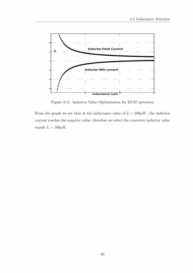
In our case V2 = 25V, V1 = 15V, Ts = 100µs, ILoad = 2.131A
With the above values, plotting the graph for L versus IMin and L versus IPeak ,
we get
39
3.5 Inductance Selection
Figure 3.11: Inductor Value Optimization for DCM operation
From the graph we see that at the inductance value of L = 100µH , the inductor
current reaches the negative value, therefore we select the converter inductor value
equals L = 100µH.
40
State Space Modeling and
Controller design
Chapter 4
State Space Modeling andController design
4.1 Introduction
The design and optimization of motor fed DC DC converter power stage circuit
parameters were shown in the previous chapter. In this chapter, the power stage
modelling is described and the circuit parameters are introduced. In section 4.2,
the necessary assumptions have been made for modeling, and consequently the
system model has been developed in section 4.3 on the basis of the state space
averaging method . The general-purposed power stage model can be used under
different operating modes. It is assumed that there exists two dc sources including
motors back EMF voltage Kw along high voltage side and low voltage side battery
source VIN , constituting the voltage sources on the both the sides of the bidirec-
tional dc-dc converter. With two voltage sources, the averaged inductor current IL
or averaged output current IA can flow in both directions, instead of flowing only
in one direction in one voltage source application . Motor’s armature resistance
RA represents either high-side source internal resistance during motoring mode
(charging) and regenerative mode (discharging) or as a load in motoring(boost)
mode. Resistor R1 is the internal resistance of the source battery for both for
modes or it acts as load during regeneration(buck) operation. Capacitor CL and
CH represents the capacitor bank of the battery and the output capacitor at motor
side respectively. Two active switches Q1 and Q2 are controlled by complementary
gating control signal Gate1 and Gate2 separately.
42
4.2 Model Assumptions
The switch Q1 is the control switch during motoring. Inductor parasitic resis-
tance RLP and MOSFET turn-on resistance RDSON are neglected in the model.
System consists of four energy storage components i.e. input capacitor C1 = 5µF ,
output capacitor C2 = 2.88mF , converter’s inductor L = 100µH and the mo-
tors armature inductance LA = 28mH, also motor acts as an electromechanical
transducer for changing the electrical energy into mechanical energy (load torque).
Further we have motor’s moment of inertia J = 0.05215kg.m2 , viscous friction
coefficient Bm = 0.002953N.m.s, motor’s armature resistance Ra = 1.4Ω, mo-
tor’s torque constant K = 0.5N.m.A−1, and load torque TL = 0.5N.m. Also we
have battery voltage Vbatt = 15V , battery’s internal resistance R1 = 0.025Ω and
converter’s nominal duty ratio D = 0.4.
4.2 Model Assumptions
Following assumptions are made before the state-space averaging method is em-
ployed for the modeling of the bidirectional dc-dc converter. The validity of the
assumptions can be verified from the simulation results, which were in agreement
with the assumptions made in our case.
Small Ripple Assumption: The inductor ripple current is assumed to be low
enough so that the state space averaging can be applied. This assumption can
be verified by comparing the simulating output with the output of the averaged
model.
Negligible Dead-Time Effect: The switching period is 100 microsecond i.e
10kHz whereas the dead time period of 1 microsecond is selected. Thus the dead
time is only approximately 1 percent of the total period, and it can be neglected.
Following the same analogy, we can also omit the soft switching period.
Identical Voltage Drop across devices during conduction in both the
modes: Since the device conduction voltage drops is very small as compared to
43
4.3 State-space Averaged Model
the DC bus voltage, therefore the variation in voltage drop among the identical
devices will even be much smaller than this fraction. Therefore , we can easily ne-
glect the voltage drop variations during the power flow in the different directions.
4.3 State-space Averaged Model
As we have already discussed about the circuit operation in the chapter 2 and 3,
it can be easily inferred that no matter the circuit is in either operating modes,
whether motoring or regenerative mode, there are always two subintervals ton
and toff as shown in Fig.4.1. Therefore we do not require to analyse the circuit
separately during motoring mode i.e. in boost mode and the regenerative mode
i.e. buck mode. Rather a simple analysis during the subintervals ton and toff will
suffice for both the modes of operation.
Figure 4.1: Complimentary Gating Signal Control
In the first subinterval, when the switch Q1 is on and Q2 is off, the converter
equivalent circuit can be represented in Fig.4.2.
There are four energy storage components , inductor currents IL, IA, and the
.battery side capacitor voltage V1 and motor side capacitor voltage V2 and the
44
4.3 State-space Averaged Model
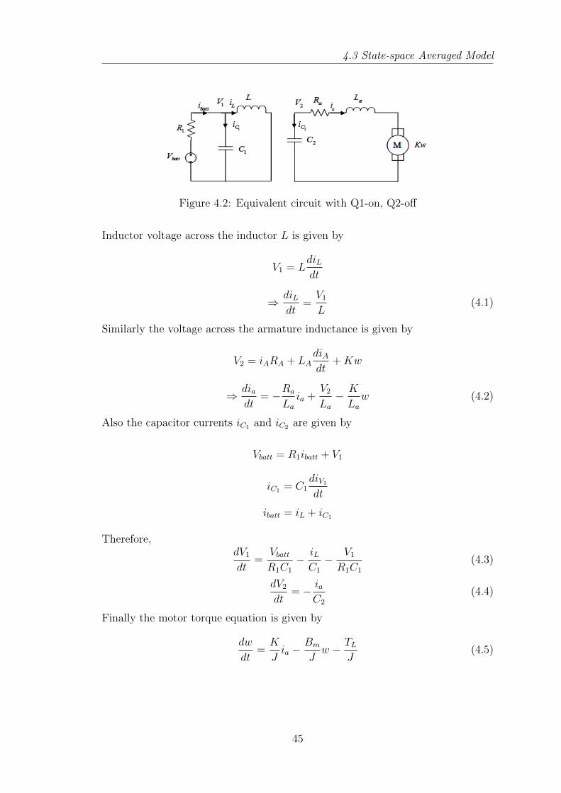
Figure 4.2: Equivalent circuit with Q1-on, Q2-off
Inductor voltage across the inductor L is given by
V1 = LdiLdt
⇒ diLdt
=V1L
(4.1)
Similarly the voltage across the armature inductance is given by
V2 = iARA + LAdiAdt
+Kw
⇒ diadt
= −Ra
La
ia +V2La
− K
La
w (4.2)
Also the capacitor currents iC1 and iC2 are given by
Vbatt = R1ibatt + V1
iC1 = C1diV1
dt
ibatt = iL + iC1
Therefore,dV1dt
=VbattR1C1
− iLC1
− V1R1C1
(4.3)
dV2dt
= − iaC2
(4.4)
Finally the motor torque equation is given by
dw
dt=K
Jia −
Bm
Jw − TL
J(4.5)
45
4.3 State-space Averaged Model
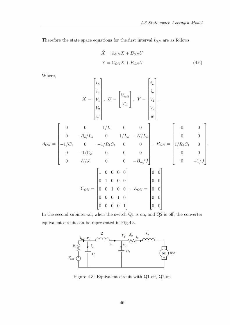
Therefore the state space equations for the first interval tON are as follows
X = AONX +BONU
Y = CONX + EONU (4.6)
Where,
X =
iL
ia
V1
V2
w
, U =
VbattTL
, Y =
iL
ia
V1
V2
w
,
AON =
0 0 1/L 0 0
0 −Ra/La 0 1/La −K/La
−1/C1 0 −1/R1C1 0 0
0 −1/C2 0 0 0
0 K/J 0 0 −Bm/J
, BON =
0 0
0 0
1/R1C1 0
0 0
0 −1/J
,
CON =
1 0 0 0 0
0 1 0 0 0
0 0 1 0 0
0 0 0 1 0
0 0 0 0 1
, EON =
0 0
0 0
0 0
0 0
0 0
In the second subinterval, when the switch Q1 is on, and Q2 is off, the converter
equivalent circuit can be represented in Fig.4.3.
Figure 4.3: Equivalent circuit with Q1-off, Q2-on
46
4.3 State-space Averaged Model
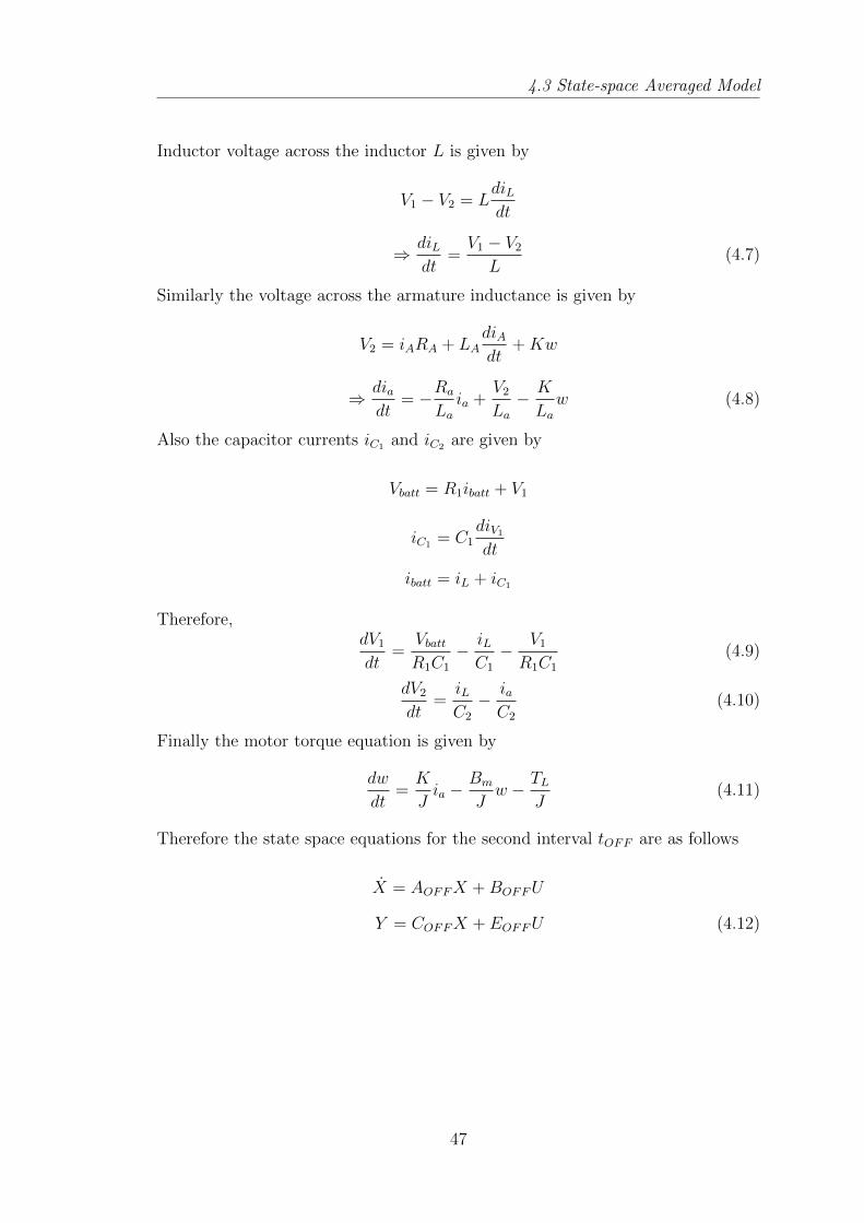
Inductor voltage across the inductor L is given by
V1 − V2 = LdiLdt
⇒ diLdt
=V1 − V2L
(4.7)
Similarly the voltage across the armature inductance is given by
V2 = iARA + LAdiAdt
+Kw
⇒ diadt
= −Ra
La
ia +V2La
− K
La
w (4.8)
Also the capacitor currents iC1 and iC2 are given by
Vbatt = R1ibatt + V1
iC1 = C1diV1
dt
ibatt = iL + iC1
Therefore,dV1dt
=VbattR1C1
− iLC1
− V1R1C1
(4.9)
dV2dt
=iLC2
− iaC2
(4.10)
Finally the motor torque equation is given by
dw
dt=K
Jia −
Bm
Jw − TL
J(4.11)
Therefore the state space equations for the second interval tOFF are as follows
X = AOFFX +BOFFU
Y = COFFX + EOFFU (4.12)
47
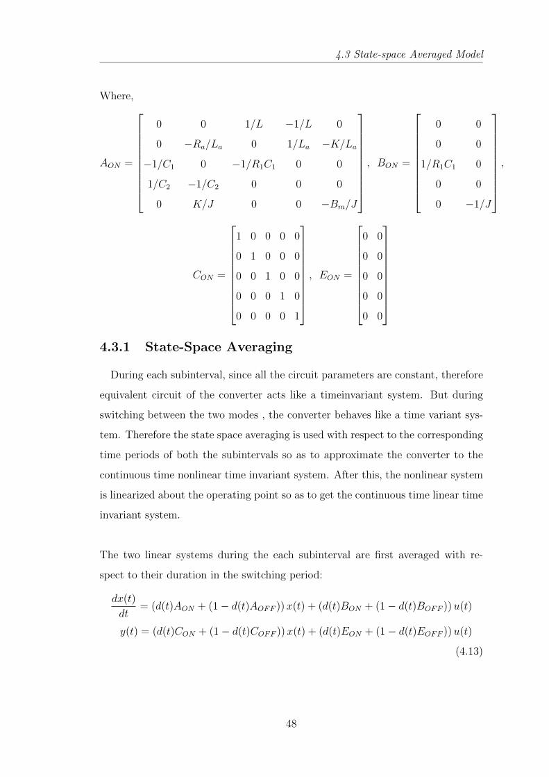
4.3 State-space Averaged Model
Where,
AON =
0 0 1/L −1/L 0
0 −Ra/La 0 1/La −K/La
−1/C1 0 −1/R1C1 0 0
1/C2 −1/C2 0 0 0
0 K/J 0 0 −Bm/J
, BON =
0 0
0 0
1/R1C1 0
0 0
0 −1/J
,
CON =
1 0 0 0 0
0 1 0 0 0
0 0 1 0 0
0 0 0 1 0
0 0 0 0 1
, EON =
0 0
0 0
0 0
0 0
0 0
4.3.1 State-Space Averaging
During each subinterval, since all the circuit parameters are constant, therefore
equivalent circuit of the converter acts like a timeinvariant system. But during
switching between the two modes , the converter behaves like a time variant sys-
tem. Therefore the state space averaging is used with respect to the corresponding
time periods of both the subintervals so as to approximate the converter to the
continuous time nonlinear time invariant system. After this, the nonlinear system
is linearized about the operating point so as to get the continuous time linear time
invariant system.
The two linear systems during the each subinterval are first averaged with re-
spect to their duration in the switching period:
dx(t)
dt= (d(t)AON + (1− d(t)AOFF ))x(t) + (d(t)BON + (1− d(t)BOFF ))u(t)
y(t) = (d(t)CON + (1− d(t)COFF ))x(t) + (d(t)EON + (1− d(t)EOFF ))u(t)
(4.13)
48
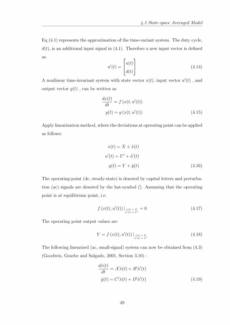
4.3 State-space Averaged Model
Eq (4.1) represents the approximation of the time-variant system. The duty cycle,
d(t), is an additional input signal in (4.1). Therefore a new input vector is defined
as.
u′(t) =
u(t)
d(t)
(4.14)
A nonlinear time-invariant system with state vector x(t), input vector u′(t) , and
output vector y(t) , can be written as
dx(t)
dt= f (x(t, u′(t))
y(t) = g (x(t, u′(t)) (4.15)
Apply linearization method, where the deviations at operating point can be applied
as follows:
x(t) = X + x(t)
u′(t) = U ′ + u′(t)
y(t) = Y + y(t) (4.16)
The operating-point (dc, steady-state) is denoted by capital letters and perturba-
tion (ac) signals are denoted by the hat-symbol (). Assuming that the operating
point is at equilibrium point, i.e.
f (x(t), u′(t)) | x(t) = Xu′(t) = U′
= 0 (4.17)
The operating point output values are
Y = f (x(t), u′(t)) | x(t) = Xu′(t) = U′
(4.18)
The following linearized (ac, small-signal) system can now be obtained from (4.3)
(Goodwin, Graebe and Salgado, 2001, Section 3.10) :
dx(t)
dt= A′x(t) +B′u′(t)
y(t) = C ′x(t) +D′u′(t) (4.19)
49
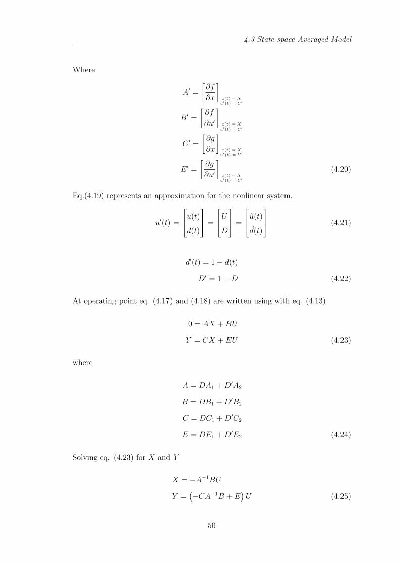
4.3 State-space Averaged Model
Where
A′ =
[∂f
∂x
]x(t) = Xu′(t) = U′
B′ =
[∂f
∂u′
]x(t) = Xu′(t) = U′
C ′ =
[∂g
∂x
]x(t) = Xu′(t) = U′
E ′ =
[∂g
∂u′
]x(t) = Xu′(t) = U′
(4.20)
Eq.(4.19) represents an approximation for the nonlinear system.
u′(t) =
u(t)
d(t)
=
UD
=
u(t)
d(t)
(4.21)
d′(t) = 1− d(t)
D′ = 1−D (4.22)
At operating point eq. (4.17) and (4.18) are written using with eq. (4.13)
0 = AX +BU
Y = CX + EU (4.23)
where
A = DA1 +D′A2
B = DB1 +D′B2
C = DC1 +D′C2
E = DE1 +D′E2 (4.24)
Solving eq. (4.23) for X and Y
X = −A−1BU
Y =(−CA−1B + E
)U (4.25)
50
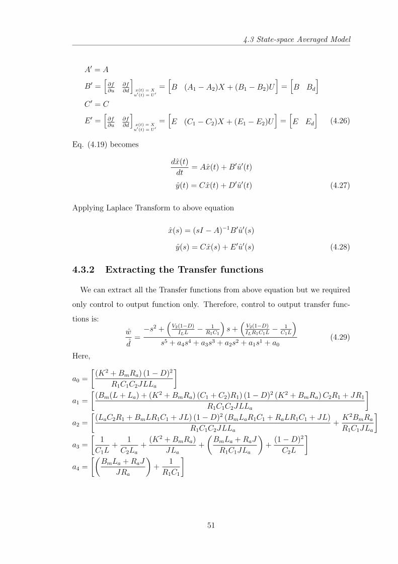
4.3 State-space Averaged Model
A′ = A
B′ =[∂f∂u
∂f∂d
]x(t) = Xu′(t) = U′
=[B (A1 − A2)X + (B1 −B2)U
]=[B Bd
]C ′ = C
E ′ =[∂f∂u
∂f∂d
]x(t) = Xu′(t) = U′
=[E (C1 − C2)X + (E1 − E2)U
]=[E Ed
](4.26)
Eq. (4.19) becomes
dx(t)
dt= Ax(t) +B′u′(t)
y(t) = Cx(t) +D′u′(t) (4.27)
Applying Laplace Transform to above equation
x(s) = (sI − A)−1B′u′(s)
y(s) = Cx(s) + E ′u′(s) (4.28)
4.3.2 Extracting the Transfer functions
We can extract all the Transfer functions from above equation but we required
only control to output function only. Therefore, control to output transfer func-
tions is:
w
d=−s2 +
(V2(1−D)
ILL− 1
R1C1
)s+
(V2(1−D)ILR1C1L
− 1C1L
)s5 + a4s4 + a3s3 + a2s2 + a1s1 + a0
(4.29)
Here,
a0 =
[(K2 +BmRa) (1−D)2
R1C1C2JLLa
]a1 =
[(Bm(L+ La) + (K2 +BmRa) (C1 + C2)R1) (1−D)2 (K2 +BmRa)C2R1 + JR1
R1C1C2JLLa
]a2 =
[(LaC2R1 +BmLR1C1 + JL) (1−D)2 (BmLaR1C1 +RaLR1C1 + JL)
R1C1C2JLLa
+K2BmRa
R1C1JLa
]a3 =
[1
C1L+
1
C2La
+(K2 +BmRa)
JLa
+
(BmLa +RaJ
R1C1JLa
)+
(1−D)2
C2L
]a4 =
[(BmLa +RaJ
JRa
)+
1
R1C1
]
51
4.4 Controller design for speed control of PMDC motor fed by Bidirectional DCDC converter:
4.4 Controller design for speed control of PMDC
motor fed by Bidirectional DC DC converter:
The averaged state space model of the power stage developed above allows us
to analyse the stability and the control issues related to the circuit. Generally the
transfer function of the unidirectional power flow in normal buck or boost mode
is easily known, but in the present case there is only one transfer function for the
power flow in both the modes i.e. motoring as well as regeneration. Therefore
the power flow depends upon the duty cycle and the instantaneous voltage across
both the sides. Since the voltage of the battery is generally fixed, the voltage
variation only exists at the input of the motor terminal i.e armature voltage and
this depends on the back emf of the motor and the duty cycle. The power can flow
in both the directions in the bidirectional dc dc converter in all the three modes
as discussed in section 3.2 depending on the armature voltage and the duty cycle.
Also the transition between the motoring and the regeneration mode can also be
estaiblished.
The smooth transition control during the power flow in the bidirectional dc-dc
converter also requires different considerations in different modes. In the present
case we have two operating modes ie motoring as well as regeneration and the and
the power flow in both the mode requires:
1. wide range output voltage regulation for wide range of the speed tracking.
2. wide range current regulation with almost constant voltage during regener-
ative braking for buck operation.
For electric vehicle, the power management needs boost power discharging mode.
At the time of startup or during acceleration, battery must provide more power
for the motor driving. Therefore we can actually control the power for the voltage
and current regulation in both the modes . Considering almost constant motor
current for the fixed load , the power flow control also means the voltage control.
Therefore voltage regulator is needed for motoring mode at constant speed. Since
52
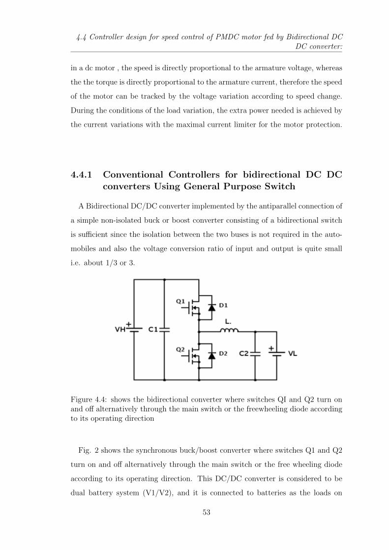
4.4 Controller design for speed control of PMDC motor fed by Bidirectional DCDC converter:
in a dc motor , the speed is directly proportional to the armature voltage, whereas
the the torque is directly proportional to the armature current, therefore the speed
of the motor can be tracked by the voltage variation according to speed change.
During the conditions of the load variation, the extra power needed is achieved by
the current variations with the maximal current limiter for the motor protection.
4.4.1 Conventional Controllers for bidirectional DC DCconverters Using General Purpose Switch
A Bidirectional DC/DC converter implemented by the antiparallel connection of
a simple non-isolated buck or boost converter consisting of a bidirectional switch
is sufficient since the isolation between the two buses is not required in the auto-
mobiles and also the voltage conversion ratio of input and output is quite small
i.e. about 1/3 or 3.
Figure 4.4: shows the bidirectional converter where switches QI and Q2 turn onand off alternatively through the main switch or the freewheeling diode accordingto its operating direction
Fig. 2 shows the synchronous buck/boost converter where switches Q1 and Q2
turn on and off alternatively through the main switch or the free wheeling diode
according to its operating direction. This DC/DC converter is considered to be
dual battery system (V1/V2), and it is connected to batteries as the loads on
53
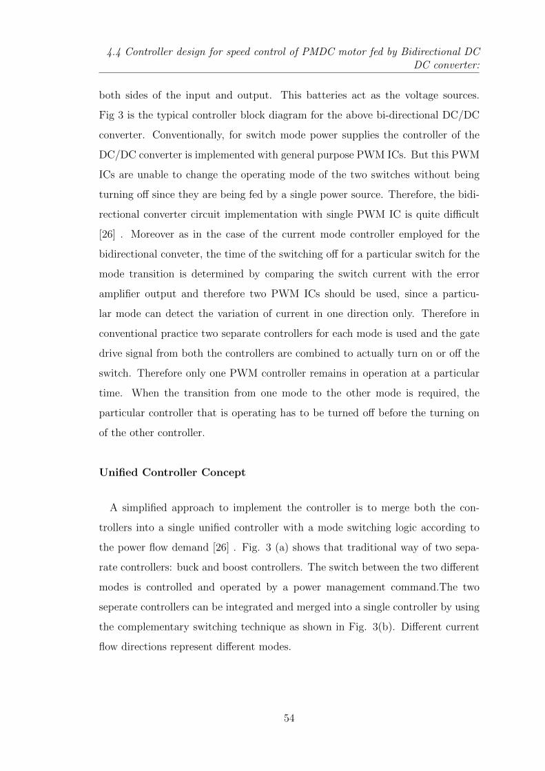
4.4 Controller design for speed control of PMDC motor fed by Bidirectional DCDC converter:
both sides of the input and output. This batteries act as the voltage sources.
Fig 3 is the typical controller block diagram for the above bi-directional DC/DC
converter. Conventionally, for switch mode power supplies the controller of the
DC/DC converter is implemented with general purpose PWM ICs. But this PWM
ICs are unable to change the operating mode of the two switches without being
turning off since they are being fed by a single power source. Therefore, the bidi-
rectional converter circuit implementation with single PWM IC is quite difficult
[26] . Moreover as in the case of the current mode controller employed for the
bidirectional conveter, the time of the switching off for a particular switch for the
mode transition is determined by comparing the switch current with the error
amplifier output and therefore two PWM ICs should be used, since a particu-
lar mode can detect the variation of current in one direction only. Therefore in
conventional practice two separate controllers for each mode is used and the gate
drive signal from both the controllers are combined to actually turn on or off the
switch. Therefore only one PWM controller remains in operation at a particular
time. When the transition from one mode to the other mode is required, the
particular controller that is operating has to be turned off before the turning on
of the other controller.
Unified Controller Concept
A simplified approach to implement the controller is to merge both the con-
trollers into a single unified controller with a mode switching logic according to
the power flow demand [26] . Fig. 3 (a) shows that traditional way of two sepa-
rate controllers: buck and boost controllers. The switch between the two different
modes is controlled and operated by a power management command.The two
seperate controllers can be integrated and merged into a single controller by using
the complementary switching technique as shown in Fig. 3(b). Different current
flow directions represent different modes.
54
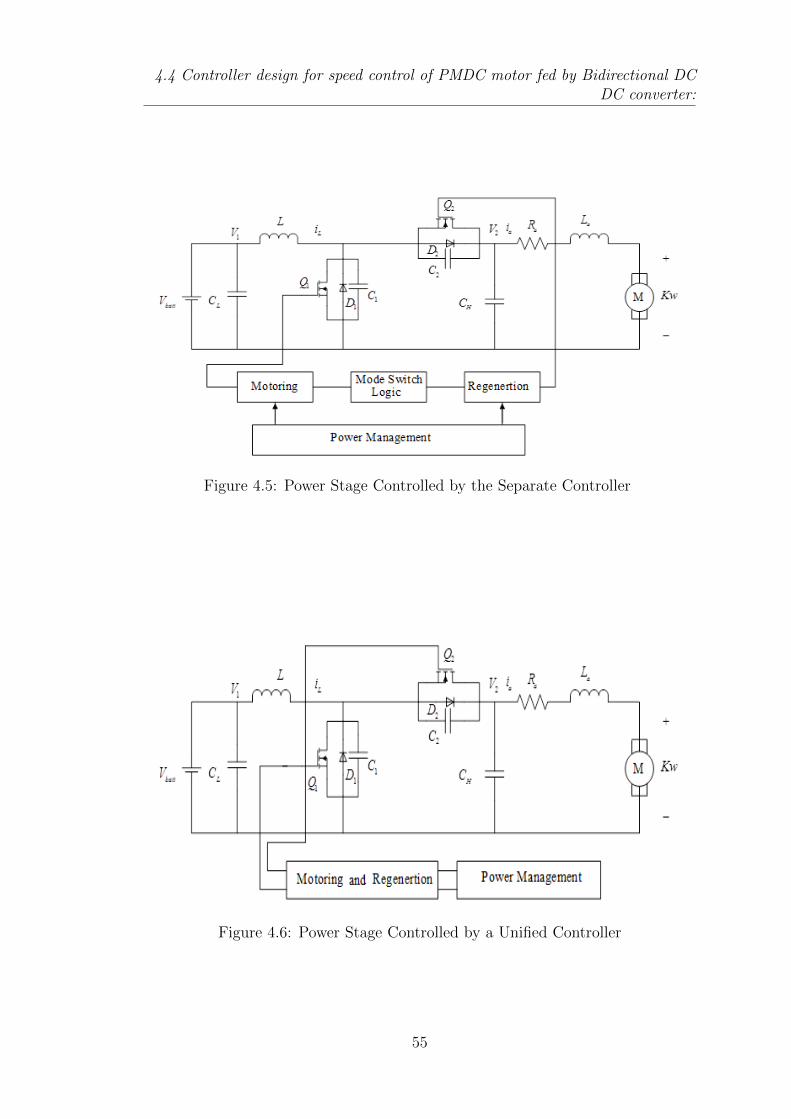
4.4 Controller design for speed control of PMDC motor fed by Bidirectional DCDC converter:
Figure 4.5: Power Stage Controlled by the Separate Controller
Figure 4.6: Power Stage Controlled by a Unified Controller
55
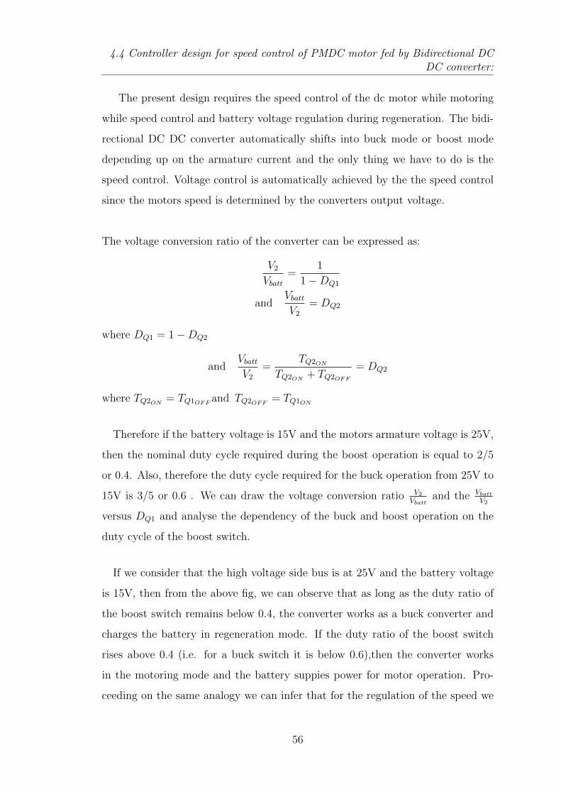
4.4 Controller design for speed control of PMDC motor fed by Bidirectional DCDC converter:
The present design requires the speed control of the dc motor while motoring
while speed control and battery voltage regulation during regeneration. The bidi-
rectional DC DC converter automatically shifts into buck mode or boost mode
depending up on the armature current and the only thing we have to do is the
speed control. Voltage control is automatically achieved by the the speed control
since the motors speed is determined by the converters output voltage.
The voltage conversion ratio of the converter can be expressed as:
V2Vbatt
=1
1−DQ1
andVbattV2
= DQ2
where DQ1 = 1−DQ2
andVbattV2
=TQ2ON
TQ2ON+ TQ2OFF
= DQ2
where TQ2ON= TQ1OFF
and TQ2OFF= TQ1ON
Therefore if the battery voltage is 15V and the motors armature voltage is 25V,
then the nominal duty cycle required during the boost operation is equal to 2/5
or 0.4. Also, therefore the duty cycle required for the buck operation from 25V to
15V is 3/5 or 0.6 . We can draw the voltage conversion ratio V2
Vbattand the Vbatt
V2
versus DQ1 and analyse the dependency of the buck and boost operation on the
duty cycle of the boost switch.
If we consider that the high voltage side bus is at 25V and the battery voltage
is 15V, then from the above fig, we can observe that as long as the duty ratio of
the boost switch remains below 0.4, the converter works as a buck converter and
charges the battery in regeneration mode. If the duty ratio of the boost switch
rises above 0.4 (i.e. for a buck switch it is below 0.6),then the converter works
in the motoring mode and the battery suppies power for motor operation. Pro-
ceeding on the same analogy we can infer that for the regulation of the speed we
56
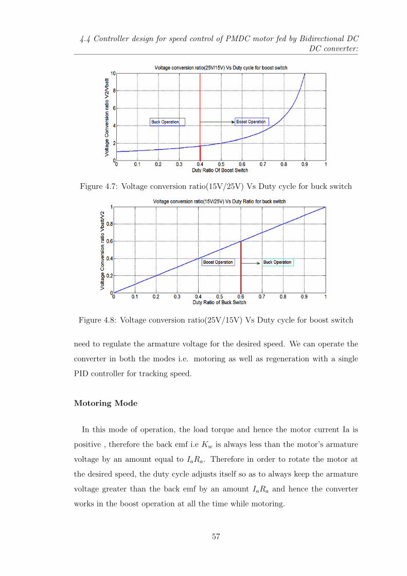
4.4 Controller design for speed control of PMDC motor fed by Bidirectional DCDC converter:
Figure 4.7: Voltage conversion ratio(15V/25V) Vs Duty cycle for buck switch
Figure 4.8: Voltage conversion ratio(25V/15V) Vs Duty cycle for boost switch
need to regulate the armature voltage for the desired speed. We can operate the
converter in both the modes i.e. motoring as well as regeneration with a single
PID controller for tracking speed.
Motoring Mode
In this mode of operation, the load torque and hence the motor current Ia is
positive , therefore the back emf i.e Kw is always less than the motor’s armature
voltage by an amount equal to IaRa. Therefore in order to rotate the motor at
the desired speed, the duty cycle adjusts itself so as to always keep the armature
voltage greater than the back emf by an amount IaRa and hence the converter
works in the boost operation at all the time while motoring.
57
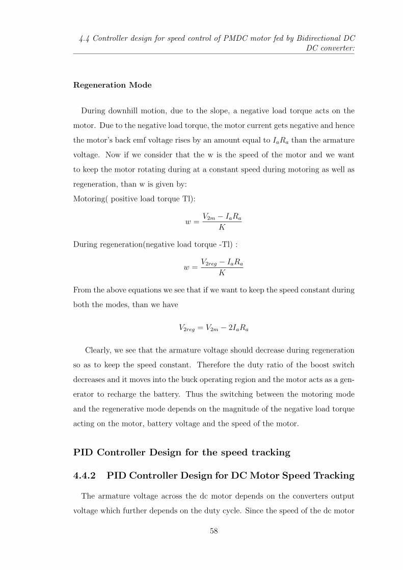
4.4 Controller design for speed control of PMDC motor fed by Bidirectional DCDC converter:
Regeneration Mode
During downhill motion, due to the slope, a negative load torque acts on the
motor. Due to the negative load torque, the motor current gets negative and hence
the motor’s back emf voltage rises by an amount equal to IaRa than the armature
voltage. Now if we consider that the w is the speed of the motor and we want
to keep the motor rotating during at a constant speed during motoring as well as
regeneration, than w is given by:
Motoring( positive load torque Tl):
w =V2m − IaRa
K
During regeneration(negative load torque -Tl) :
w =V2reg − IaRa
K
From the above equations we see that if we want to keep the speed constant during
both the modes, than we have
V2reg = V2m − 2IaRa
Clearly, we see that the armature voltage should decrease during regeneration
so as to keep the speed constant. Therefore the duty ratio of the boost switch
decreases and it moves into the buck operating region and the motor acts as a gen-
erator to recharge the battery. Thus the switching between the motoring mode
and the regenerative mode depends on the magnitude of the negative load torque
acting on the motor, battery voltage and the speed of the motor.
PID Controller Design for the speed tracking
4.4.2 PID Controller Design for DC Motor Speed Tracking
The armature voltage across the dc motor depends on the converters output
voltage which further depends on the duty cycle. Since the speed of the dc motor
58
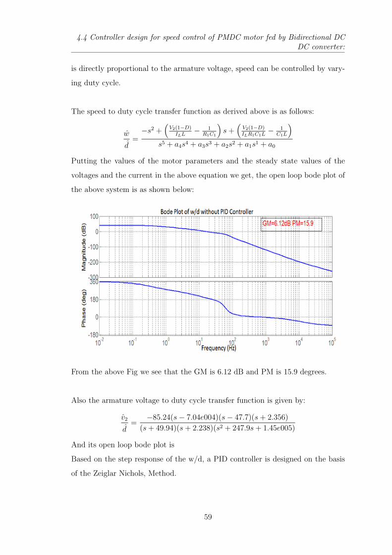
4.4 Controller design for speed control of PMDC motor fed by Bidirectional DCDC converter:
is directly proportional to the armature voltage, speed can be controlled by vary-
ing duty cycle.
The speed to duty cycle transfer function as derived above is as follows:
w
d=−s2 +
(V2(1−D)
ILL− 1
R1C1
)s+
(V2(1−D)ILR1C1L
− 1C1L
)s5 + a4s4 + a3s3 + a2s2 + a1s1 + a0
Putting the values of the motor parameters and the steady state values of the
voltages and the current in the above equation we get, the open loop bode plot of
the above system is as shown below:
From the above Fig we see that the GM is 6.12 dB and PM is 15.9 degrees.
Also the armature voltage to duty cycle transfer function is given by:
v2
d=
−85.24(s− 7.04e004)(s− 47.7)(s+ 2.356)
(s+ 49.94)(s+ 2.238)(s2 + 247.9s+ 1.45e005)
And its open loop bode plot is
Based on the step response of the w/d, a PID controller is designed on the basis
of the Zeiglar Nichols, Method.
59
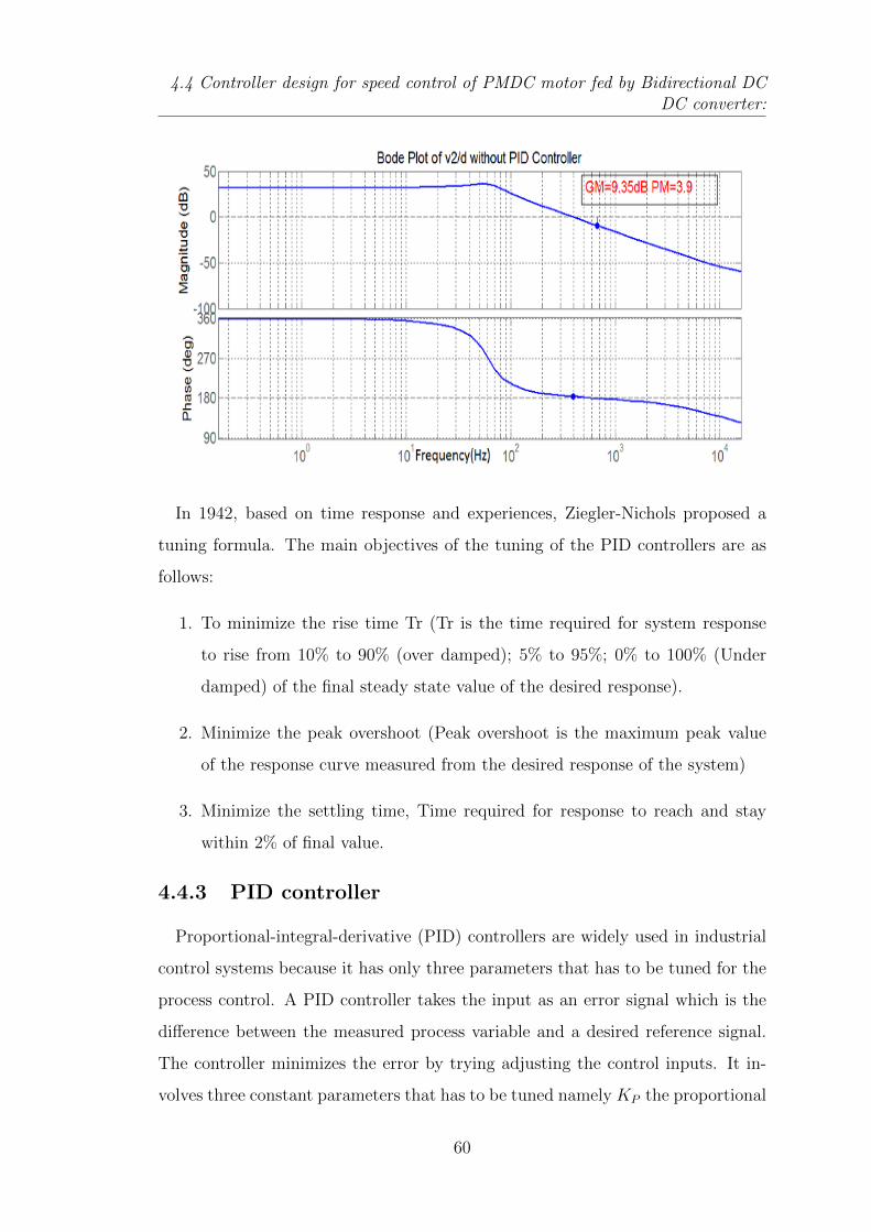
4.4 Controller design for speed control of PMDC motor fed by Bidirectional DCDC converter:
In 1942, based on time response and experiences, Ziegler-Nichols proposed a
tuning formula. The main objectives of the tuning of the PID controllers are as
follows:
1. To minimize the rise time Tr (Tr is the time required for system response
to rise from 10% to 90% (over damped); 5% to 95%; 0% to 100% (Under
damped) of the final steady state value of the desired response).
2. Minimize the peak overshoot (Peak overshoot is the maximum peak value
of the response curve measured from the desired response of the system)
3. Minimize the settling time, Time required for response to reach and stay
within 2% of final value.
4.4.3 PID controller
Proportional-integral-derivative (PID) controllers are widely used in industrial
control systems because it has only three parameters that has to be tuned for the
process control. A PID controller takes the input as an error signal which is the
difference between the measured process variable and a desired reference signal.
The controller minimizes the error by trying adjusting the control inputs. It in-
volves three constant parameters that has to be tuned namely KP the proportional
60
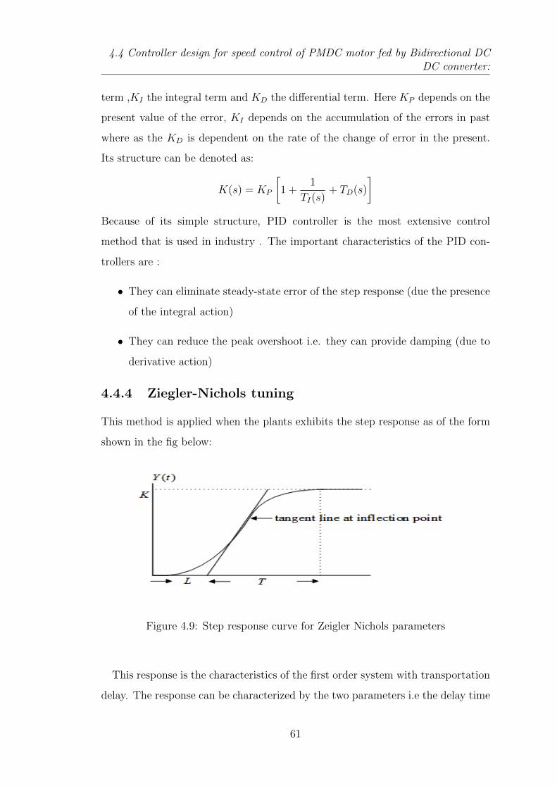
4.4 Controller design for speed control of PMDC motor fed by Bidirectional DCDC converter:
term ,KI the integral term and KD the differential term. Here KP depends on the
present value of the error, KI depends on the accumulation of the errors in past
where as the KD is dependent on the rate of the change of error in the present.
Its structure can be denoted as:
K(s) = KP
[1 +
1
TI(s)+ TD(s)
]Because of its simple structure, PID controller is the most extensive control
method that is used in industry . The important characteristics of the PID con-
trollers are :
• They can eliminate steady-state error of the step response (due the presence
of the integral action)
• They can reduce the peak overshoot i.e. they can provide damping (due to
derivative action)
4.4.4 Ziegler-Nichols tuning
This method is applied when the plants exhibits the step response as of the form
shown in the fig below:
Figure 4.9: Step response curve for Zeigler Nichols parameters
This response is the characteristics of the first order system with transportation
delay. The response can be characterized by the two parameters i.e the delay time
61
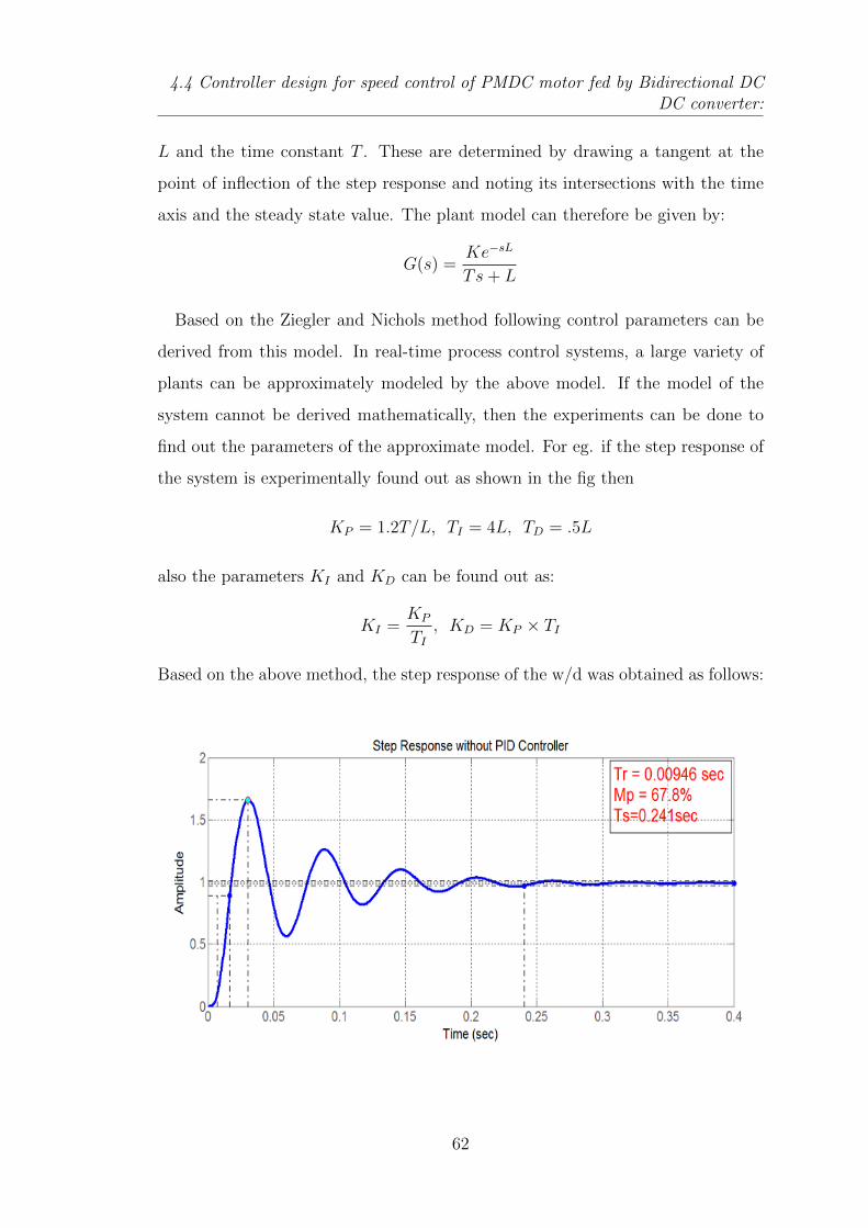
4.4 Controller design for speed control of PMDC motor fed by Bidirectional DCDC converter:
L and the time constant T . These are determined by drawing a tangent at the
point of inflection of the step response and noting its intersections with the time
axis and the steady state value. The plant model can therefore be given by:
G(s) =Ke−sL
Ts+ L
Based on the Ziegler and Nichols method following control parameters can be
derived from this model. In real-time process control systems, a large variety of
plants can be approximately modeled by the above model. If the model of the
system cannot be derived mathematically, then the experiments can be done to
find out the parameters of the approximate model. For eg. if the step response of
the system is experimentally found out as shown in the fig then
KP = 1.2T/L, TI = 4L, TD = .5L
also the parameters KI and KD can be found out as:
KI =KP
TI, KD = KP × TI
Based on the above method, the step response of the w/d was obtained as follows:
62
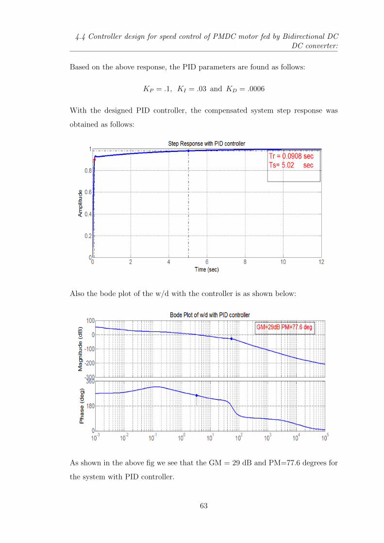
4.4 Controller design for speed control of PMDC motor fed by Bidirectional DCDC converter:
Based on the above response, the PID parameters are found as follows:
KP = .1, KI = .03 and KD = .0006
With the designed PID controller, the compensated system step response was
obtained as follows:
Also the bode plot of the w/d with the controller is as shown below:
As shown in the above fig we see that the GM = 29 dB and PM=77.6 degrees for
the system with PID controller.
63

Simulation and Results
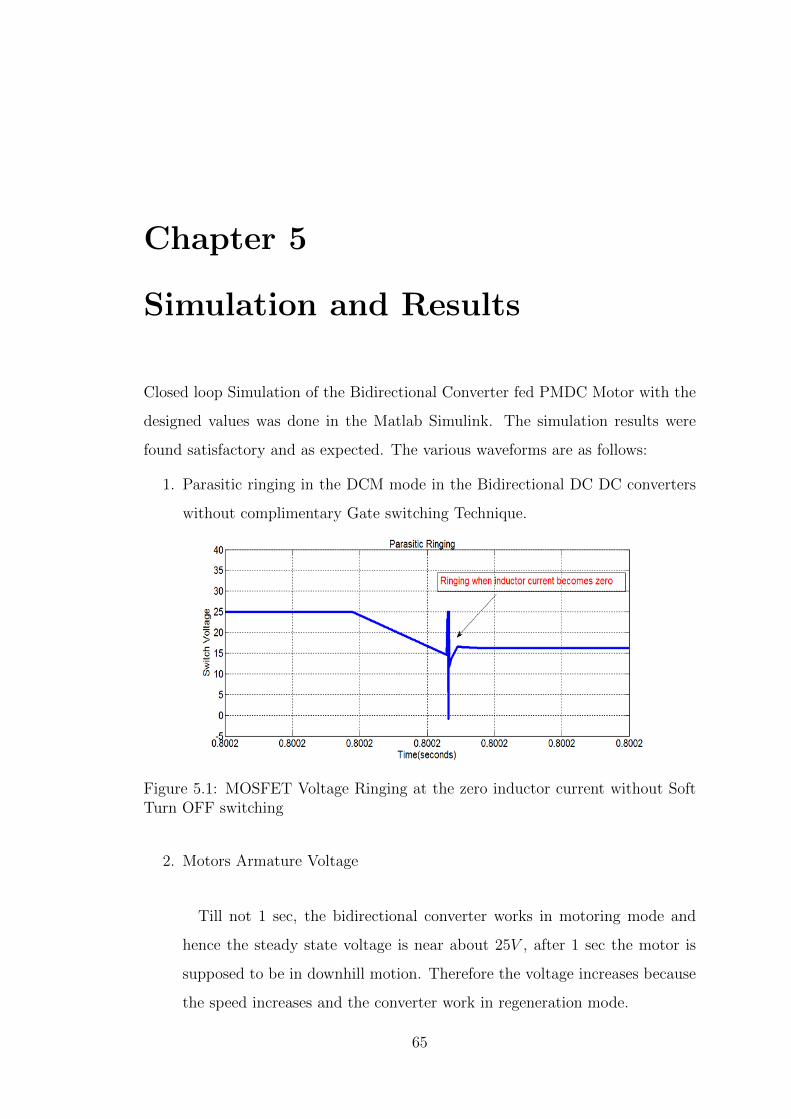
Chapter 5
Simulation and Results
Closed loop Simulation of the Bidirectional Converter fed PMDC Motor with the
designed values was done in the Matlab Simulink. The simulation results were
found satisfactory and as expected. The various waveforms are as follows:
1. Parasitic ringing in the DCM mode in the Bidirectional DC DC converters
without complimentary Gate switching Technique.
Figure 5.1: MOSFET Voltage Ringing at the zero inductor current without SoftTurn OFF switching
2. Motors Armature Voltage
Till not 1 sec, the bidirectional converter works in motoring mode and
hence the steady state voltage is near about 25V , after 1 sec the motor is
supposed to be in downhill motion. Therefore the voltage increases because
the speed increases and the converter work in regeneration mode.
65
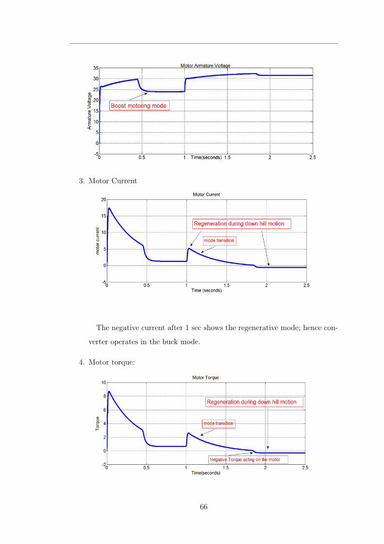
3. Motor Current
The negative current after 1 sec shows the regenerative mode; hence con-
verter operates in the buck mode.
4. Motor torque:
66
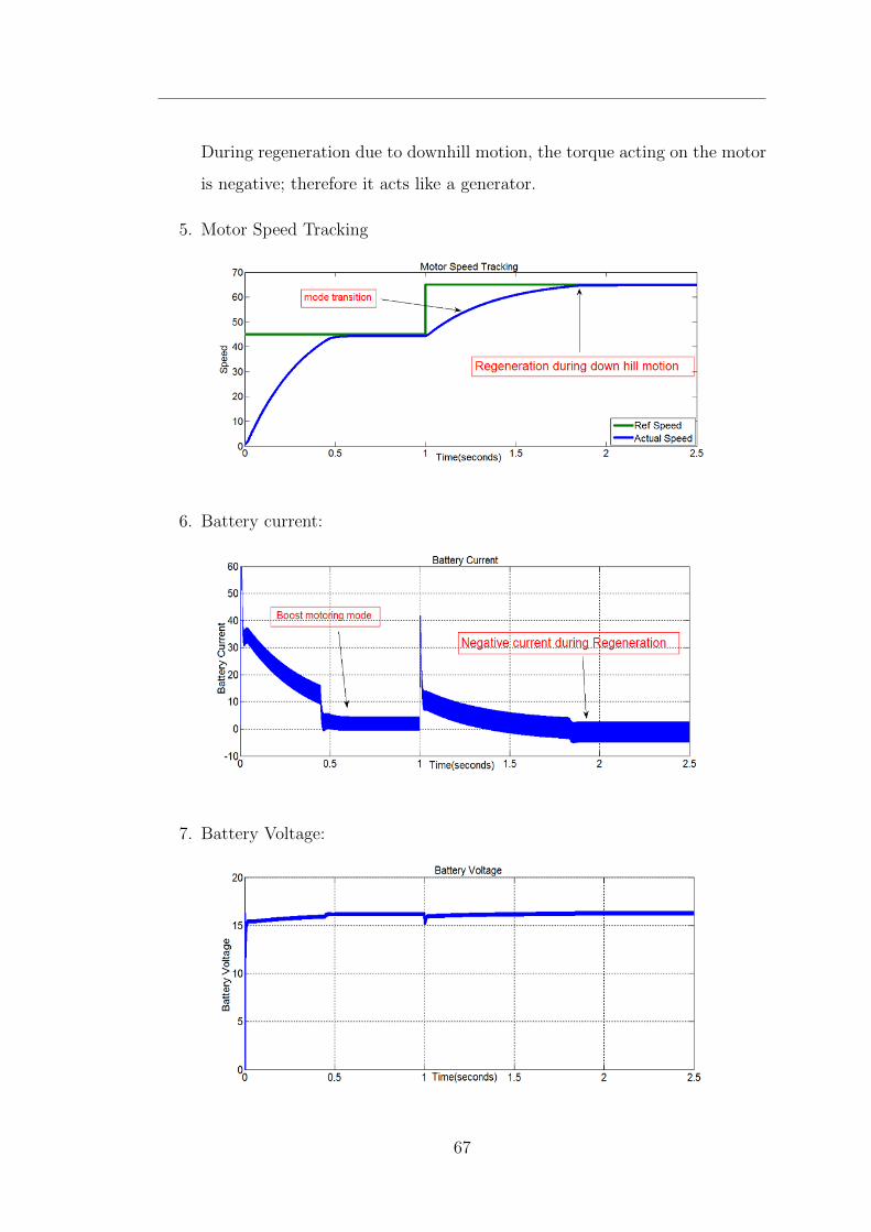
During regeneration due to downhill motion, the torque acting on the motor
is negative; therefore it acts like a generator.
5. Motor Speed Tracking
6. Battery current:
7. Battery Voltage:
67
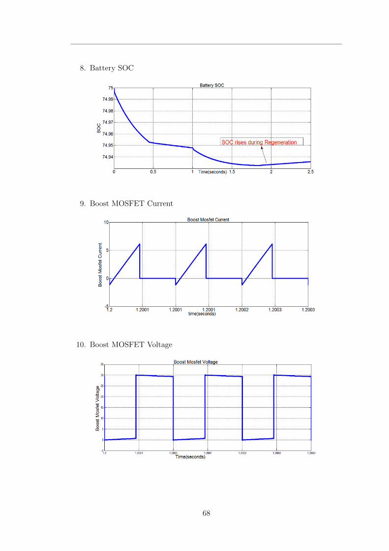
8. Battery SOC
9. Boost MOSFET Current
10. Boost MOSFET Voltage
68
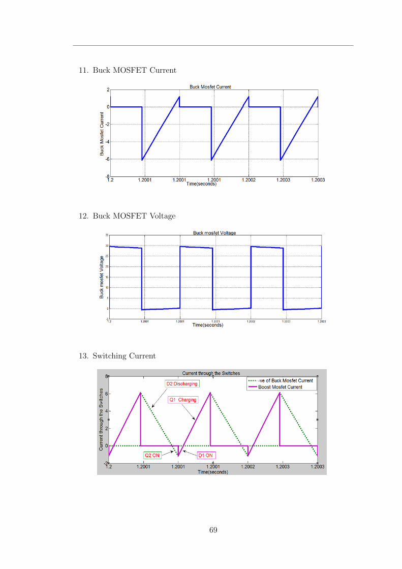
11. Buck MOSFET Current
12. Buck MOSFET Voltage
13. Switching Current
69
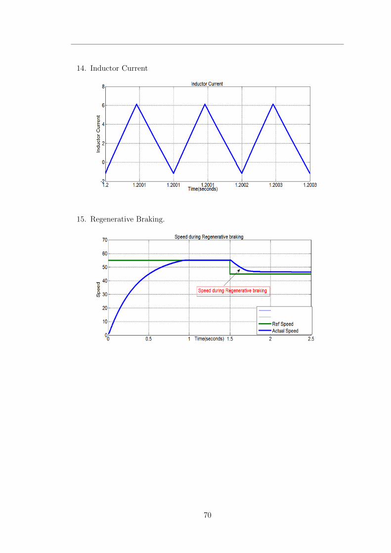
14. Inductor Current
15. Regenerative Braking.
70
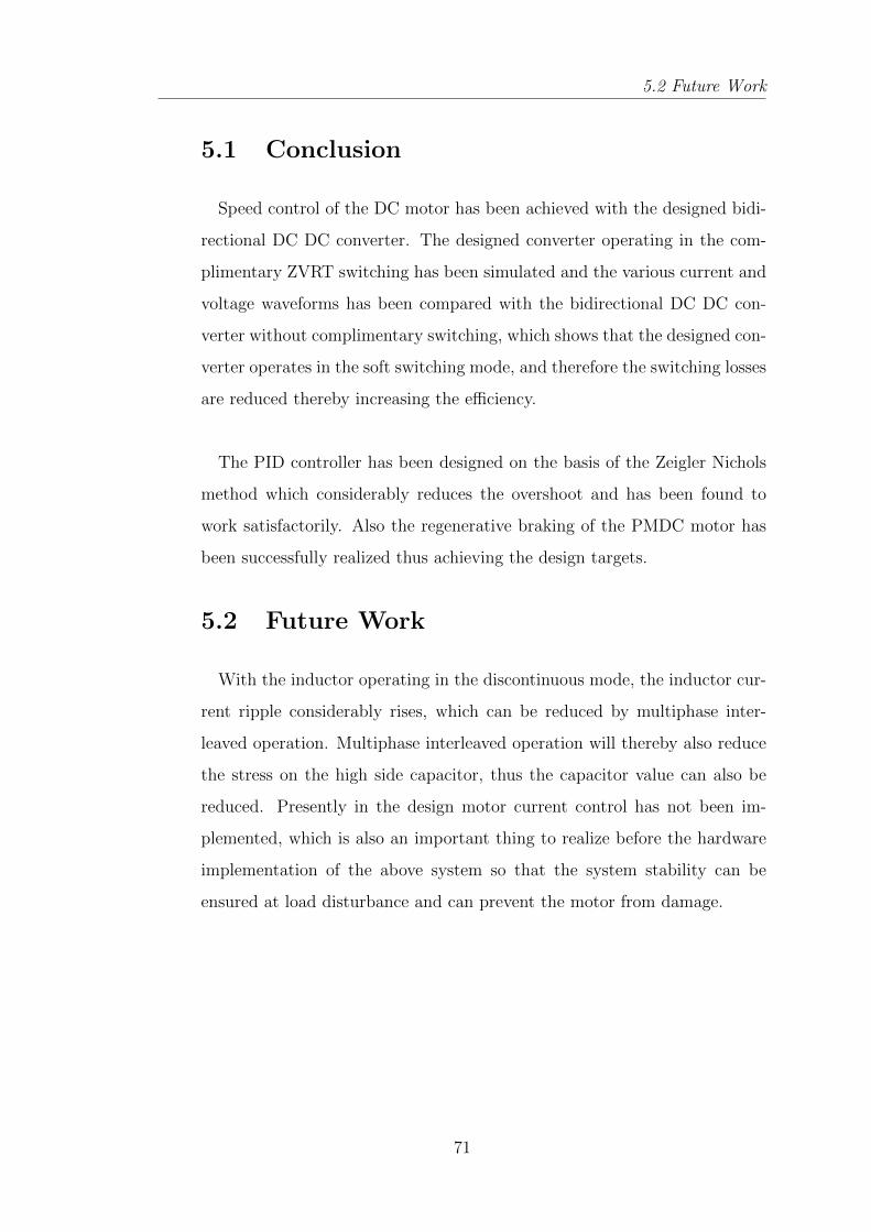
5.2 Future Work
5.1 Conclusion
Speed control of the DC motor has been achieved with the designed bidi-
rectional DC DC converter. The designed converter operating in the com-
plimentary ZVRT switching has been simulated and the various current and
voltage waveforms has been compared with the bidirectional DC DC con-
verter without complimentary switching, which shows that the designed con-
verter operates in the soft switching mode, and therefore the switching losses
are reduced thereby increasing the efficiency.
The PID controller has been designed on the basis of the Zeigler Nichols
method which considerably reduces the overshoot and has been found to
work satisfactorily. Also the regenerative braking of the PMDC motor has
been successfully realized thus achieving the design targets.
5.2 Future Work
With the inductor operating in the discontinuous mode, the inductor cur-
rent ripple considerably rises, which can be reduced by multiphase inter-
leaved operation. Multiphase interleaved operation will thereby also reduce
the stress on the high side capacitor, thus the capacitor value can also be
reduced. Presently in the design motor current control has not been im-
plemented, which is also an important thing to realize before the hardware
implementation of the above system so that the system stability can be
ensured at load disturbance and can prevent the motor from damage.
71
Bibliography
[1] Emadi, Ali, Kaushik Rajashekara, Sheldon S. Williamson, and Srdjan
M. Lukic,“Topological overview of hybrid electric and fuel cell vehicular
power system architectures and configurations,”IEEE Transactions on
Vehicular Technology, 54, no. 3 (2005): 763-770.
[2] Chan, C. C., Alain Bouscayrol, and Keyu Chen,“Electric, hybrid, and
fuel-cell vehicles: Architectures and modeling,”IEEE Transactions on
Vehicular Technology, 59, no. 2 (2010): 589-598.
[3] Emadi, Ali, Young Joo Lee, and Kaushik Rajashekara,“Power electron-
ics and motor drives in electric, hybrid electric, and plug-in hybrid
electric vehicles,”IEEE Transactions on Industrial Electronics, 55, no.
6 (2008): 2237-2245.
[4] Cagatay Bayindir, Kamil, Mehmet Ali Gzkk, and Ahmet Teke,“A
comprehensive overview of hybrid electric vehicle: Powertrain con-
figurations, powertrain control techniques and electronic control
units,”Energy Conversion and Management,52, no. 2 (2011): 1305-
1313.
[5] Amjadi, Zahra, and Sheldon S. Williamson,“Power-electronics-based so-
lutions for plug-in hybrid electric vehicle energy storage and manage-
ment systems,” IEEE Transactions on Industrial Electronics,57, no. 2
(2010): 608-616.
[6] Karshenas, Hamid R., Hamid Daneshpajooh, Alireza Safaee, Praveen
Jain, and Alireza Bakhshai,“Bidirectional DC-DC Converters for En-
72
Bibliography
ergy Storage Systems,”Energy Storage in the Emerging Era of Smart
Grids, Rosario Carbone (Ed.),ISBN: 978-953.
[7] Caricchi, F., F. Crescimbini, F. Giulii Capponi, and L. Solero,“Study of
bi-directional buck-boost converter topologies for application in electri-
cal vehicle motor drives,”In Applied Power Electronics Conference and
Exposition, 1998. APEC’98. Conference Proceedings 1998., Thirteenth
Annual,vol. 1, pp. 287-293. IEEE, 1998.
[8] Cao, Jian, and Ali Emadi,“A new battery/ultracapacitor hybrid energy
storage system for electric, hybrid, and plug-in hybrid electric vehi-
cles,”IEEE Transactions on Power Electronics,27.1 (2012): 122-132.
[9] Lee, Young-Joo, Alireza Khaligh, and Ali Emadi,“Advanced integrated
bidirectional AC/DC and DC/DC converter for plug-in hybrid electric
vehicles,”IEEE Transactions on Vehicular Technology,58, no. 8 (2009):
3970-3980.
[10] Liu, Wei-Shih, Jiann-Fuh Chen, Tsorng-Juu Liang, Ray-Lee Lin, and
Ching-Hsiung Liu,“Analysis, design, and control of bidirectional cas-
coded configuration for a fuel cell hybrid power system,”IEEE Trans-
actions on Power Electronics 25, no. 6 (2010): 1565-1575.
[11] Shen, Z. John, and Ichiro Omura,“Power semiconductor devices for hy-
brid, electric, and fuel cell vehicles,”Proceedings of the IEEE 2007 95,
no. 4 (2007): 778-789.
[12] Ke, Yu-Lung, Ying-Chun Chuang, and Hung-Shiang Chuang,“Energy
recovery electric bicycle with two-quadrant DC motor drivers,”In Indus-
try Applications Society Annual Meeting, 2009. IAS 2009. IEEE ,pp.
1-7. IEEE, 2009.
[13] Schupbach, Roberto M., and Juan C. Balda,“Comparing DC-DC con-
verters for power management in hybrid electric vehicles,”In Electric
Machines and Drives Conference, 2003. IEMDC’03. IEEE Interna-
tional , vol. 3, pp. 1369-1374. IEEE, 2003.
73
Bibliography
[14] Han, Sangtaek, and Deepak Divan,“Bi-directional DC/DC convert-
ers for plug-in hybrid electric vehicle (PHEV) applications,”In Ap-
plied Power Electronics Conference and Exposition, 2008. APEC 2008.
Twenty-Third Annual IEEE ,pp. 784-789. IEEE, 2008.
[15] Zeraoulia, Mounir, Mohamed El Hachemi Benbouzid, and Demba Di-
allo,“Electric motor drive selection issues for HEV propulsion systems:
A comparative study,” IEEE Transactions on Vehicular Technology, 55,
no. 6 (2006): 1756-1764.
[16] Xue, X. D., K. Cheng, and N. C. Cheung,“Selection of electric mo-
tor drives for electric vehicles,”In Power Engineering Conference, 2008.
AUPEC’08. Australasian Universities, pp. 1-6. IEEE, 2008.
[17] Williamson, S., M. Lukic, and Ali Emadi,“Comprehensive drive train ef-
ficiency analysis of hybrid electric and fuel cell vehicles based on motor-
controller efficiency modeling,”IEEE Transactions on Power Electronics
, 21, no. 3 (2006): 730-740.
[18] Sripakagorn, Angkee, and Nartnarong Limwuthigraijirat,“Experimental
assessment of fuel cell/supercapacitor hybrid system for scoot-
ers,”International journal of hydrogen energy 34, no. 15 (2009): 6036-
6044.
[19] Zhang, Junhong. Bidirectional DC-DC Power Converter Design Opti-
mization,“Modeling and Control. Diss. Virginia Polytechnic Institute
and State University,”2008.
[20] Xu, Haiping, Xuhui Wen, Ermin Qiao, Xin Guo, and Li Kong,“High
power interleaved boost converter in fuel cell hybrid electric vehi-
cle,”IEEE International Conference on Electric Machines and Drives,
2005 , pp. 1814-1819. IEEE, 2005.
[21] Huang, Xudong, Xiaoyan Wang, Troy Nergaard, Jih-Sheng Lai, Xingyi
Xu, and Lizhi Zhu,“Parasitic ringing and design issues of digitally con-
trolled high power interleaved boost converters,”IEEE Transactions on
Power Electronics, 19, no. 5 (2004): 1341-1352.
74
Bibliography
[22] Zhang, Junhong, Jih-Sheng Lai, Rae-Young Kim, and Wensong
Yu,“High-power density design of a soft-switching high-power bidirec-
tional dcdc converter,”IEEE Transactions on Power Electronics, 22, no.
4 (2007): 1145-1153.
[23] Hua, Guichao, and Fred C. Lee,“Soft-switching techniques in PWM con-
verters,”IEEE Transactions on Industrial Electronics, 42, no. 6 (1995):
595-603.
[24] Canales, Francisco, Peter Barbosa, and Fred C. Lee,“A zero-voltage
and zero-current switching three-level DC/DC converter,”IEEE Trans-
actions on Power Electronics, 17, no. 6 (2002): 898-904.
[25] Liu, K-H., and Fred CY Lee,“Zero-voltage switching technique in
DC/DC converters,”IEEE Transactions on Power Electronics, 5, no.
3 (1990): 293-304.
[26] Yoo, Chang-Gyu, Woo-Cheol Lee, KyuChan Lee, and Inyoung
Suh,“Current mode PWM controller for a 42V/14V bidirectional
DC/DC converter,”In Power Electronics Specialists Conference, 2006.
PESC’06. 37th IEEE, pp. 1-6. IEEE, 2006.
[27] Yoo, ChangGyu, Woo-Cheol Lee, Kyu-Chan Lee, and Bo H.
Cho,“Transient current suppression scheme for bi-directional DC-DC
converters in 42 V automotive power systems,”In Applied Power Elec-
tronics Conference and Exposition, 2005. APEC 2005. Twentieth An-
nual IEEE, vol. 3, pp. 1600-1604. IEEE, 2005.
[28] Huang, Xudong, Troy Nergaard, Jih-Sheng Lai, Xingyi Xu, and Lizhi
Zhu,“A DSP based controller for high-power interleaved boost convert-
ers,”In Applied Power Electronics Conference and Exposition, 2003.
APEC’03. Eighteenth Annual IEEE, vol. 1, pp. 327-333. 2003.
[29] Hwang, Sentai, and J. Chou,“Comparison on fuzzy logic and PID con-
trols for a DC motor position controller,”In Industry Applications So-
ciety Annual Meeting, 1994., Conference Record of the 1994 IEEE, pp.
1930-1935. IEEE, 1994.
75
![HIGH-CONVERSION-RATIO BIDIRECTIONAL DC–DC ......bidirectional dc –dc converter with a high convention ratio is a key component of battery applications [5] Isolated bidirectional](https://img.pdfslide.net/doc/110x75/5f0a32787e708231d42a7b2d/high-conversion-ratio-bidirectional-dcadc-bidirectional-dc-adc-converter.jpg)