Embed Size (px)
Citation preview
Modeling Force Transfer around Openings inWood-Frame Shear Walls
Minghao Li, A.M.ASCE1; Frank Lam, M.ASCE2; Borjen Yeh, M.ASCE3; Tom Skaggs4;Doug Rammer, M.ASCE5; and James Wacker, M.ASCE6
Abstract: This paper presented amodeling study on force transfer around openings (FTAO) in wood-frame shear walls detailed for FTAO. Tounderstand the load transfer in the walls, this study used a finite-element modelWALL2D, which is able to model individual wall components,including framing members, sheathing panels, oriented panel-frame nailed connections, framing connections, hold-down connections, andstrap connections for reinforcing the corners of openings. The various wall models were validated through laboratory testing of 12 full-scale 2.44 3 3.66 m (89 3 129) shear wall configurations, which included a variety of opening types and sizes. At the wall design loadlevel, the predicted strap forces around openings also agreed well with the test results, in contrast with four simplified analytical methodscommonly used in designing shear walls with openings detailed for FTAO. This wall model thus presents a useful tool to check the accuracy ofthe simplified methods and develop a better understanding of the behavior of wood-frame shear walls with openings.DOI: 10.1061/(ASCE)ST.1943-541X.0000592. © 2012 American Society of Civil Engineers.
CE Database subject headings: Frames; Shear walls; Wood; Finite element method.
Author keywords: Wood frame; Shear walls; openings; Force transfer; Finite-element model.
Introduction
Wood structural panel sheathed shear walls are important lateralforce resisting components in wood-frame construction to resistseismic or wind loads. Wall openings for windows and doors,however, can greatly reduce shear wall resistance because of thediscontinuity of load transfers, as well as highforce concentrationaround openings. Currently, the building code in theU.S. [AmericanNational Standards Institute (ANSI) / American Forest & PaperAssociation (AF&PA) 2005] provides three solutions to designwood-frame shear walls with openings. The first solution, also usedin the Canadian code [Canadian Standard Association (CSA) 2005],is so-called segmented shear wall design method, which considersonly full-height wall segments and ignores contributions from wallsegments above and below openings. The second solution takes intoaccount wall segments above and below openings by introducinga shear capacity adjustment factor Co, considering maximum
opening height and the percentage of full-height sheathing(Sugiyama 1981). These walls with openings are not designed forforce transfer around the openings (FTAO). The last solution, whichhas been used in engineering practice for a long time, is called theFTAOmethod, in which shear walls with openings are designed anddetailed for FTAO so that nails, metal straps, and blocking membersmay be required to transfer loads and reinforce corners of openings.In the FTAO method, a rational analysis is required to estimate theforce transfer and choose proper metal connectors. In recent years,the FTAO method has been a subject of interest by the engineeringcommunity, such as the Structural Engineers Association of Cal-ifornia (SEAOC). Among various calculation methods generallyaccepted as rational analyses in practice, drag strut, cantilever beam,and Diekmann’s method are most commonly used. However,variations in internal forces calculated by the different methodsresult in some walls being either overbuilt or less reliable than theintended performance objective. Martin (2005) presented a detailedreview of commonly used design methods of shear walls: thesegmented shear wall method, the drag strut method, and thecantilevered beam analog. Depending on wall geometries, the dragstrut method and the cantilevered beam method can yield verydifferent estimates. Diekmann (2005) discussedMartin’s article andpresented amethod he had introduced previously based onVierendeeltruss analog (Diekmann 1997). Kolba (2000) performed a detailedexperimental study on shear walls with openings detailed for FTAOfocusing on the applicability of Diekmann’s method. Although theresults were inconclusive, detailed explanations of the assumptionsused by Diekmann’s method were provided. Robertson (2004)discussed different methods available to engineers for analyzing anddesigning FTAO in plywood sheathed shearwalls. He also discussedbuilding code requirements and analyzed several examples of wallconfigurations using the drag strut method, the cantilevered beammethod, and the coupled beam analogy (a variant of Diekmann’smethod that seems to lack some equilibrium rigor). Large differencesin estimated FTAO values were also found. Lam (2010) also
1Postdoctoral Research Fellow, Dept. of Wood Science, Univ. of BritishColumbia, Vancouver, BC, Canada, BC V6T 1Z4 (corresponding author).E-mail: [email protected].
2Professor, Dept. of Wood Science, Univ. of British Columbia,Vancouver, BC, Canada, V6T 1Z4.
3Director, Technical Services, APAeThe EngineeredWood Association,7011 S. 19th Street, Tacoma, WA 98466-5333.
4Manager, ProductEvaluation,TechnicalServices,APAeTheEngineeredWood Association, 7011 S. 19th Street, Tacoma, WA 98466-5333.
5Research General Engineer, Forest Products Laboratory, USDA, 1 Gif-ford Pinchot Dr., Madison, WI 53726.
6Research General Engineer, Forest Products Laboratory, USDA, 1 Gif-ford Pinchot Dr., Madison, WI 53726.
Note. This manuscript was submitted on August 25, 2011; approved onFebruary 17, 2012; published online on February 22, 2012. Discussionperiod open until May 1, 2013; separate discussions must be submitted forindividual papers. This paper is part of the Journal of Structural Engi-neering, Vol. 138, No. 12, December 1, 2012. ©ASCE, ISSN 0733-9445/2012/12-1419e1426/$25.00.
JOURNAL OF STRUCTURAL ENGINEERING © ASCE / DECEMBER 2012 / 1419
J. Struct. Eng. 2012.138:1419-1426.
Dow
nloa
ded
from
asc
elib
rary
.org
by
GR
AIN
GE
R E
NG
INE
ER
ING
LIB
E o
n 05
/14/
13. C
opyr
ight
ASC
E. F
or p
erso
nal u
se o
nly;
all
righ
ts r
eser
ved.
reviewed these four methods and compared the estimates of max-imum FTAO in five wall configurations. It was also found that thesemethods may give significantly different results.
Previous studies on wood-frame shear walls with openingsmainly focused on experimental studies and modeling of perforatedwalls that are not designed for FTAO. The main objective was toinvestigate the influence of the openings on shear wall capacity andto derive empirical reduction factors that can be directly used fordesign purposes. Andreasson et al. (2002) studied perforated wood-frame walls using finite element modeling to check the validity ofassumptions on pinned or rigid framing connections in a shear wallmodel. The effect of partially and fully hold-down anchoring on full-height wall piers was also studied. Doudak et al. (2006) studied themonotonic behavior of five perforated wall configurations usingexperimental studies and computer modeling in SAP2000 software(SAP2000). The effect of hold-down anchoring was also studied. Nocomputer modeling work has been reported to study the behaviorof wood-frame shear walls with openings particularly detailedfor FTAO.
To develop a better understanding of the FTAO problem inwood-frame shear walls, in this study, a shear wall model calledWALL2D was used to investigate eight configurations of shearwalls detailed for FTAO with different opening sizes and differentlengths of full-height wall piers. To check the model validity, itspredictions were then compared with test results in terms of theglobal wall load-drift responses and the internal forces transferredaround the openings. The FTAO values estimated by the fourcommonly used design methods were also presented. Some sug-gestions on estimating the FTAO were also provided according tothe shear wall test program and the modeling work.
Shear Wall Test Program
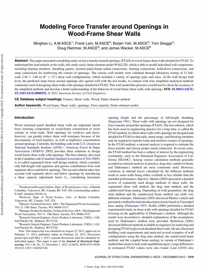
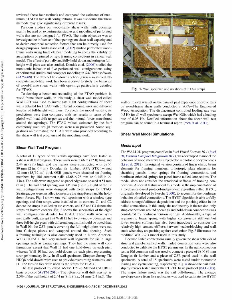
A total of 12 types of walls with openings have been tested ina shear wall test program. These walls were 3.66 m (12 ft) long and2.44 m (8 ft) high, and the frames were constructed with 38389 mm ð2 in:3 4 in:Þ Douglas fir lumber. APA STR-1erated12 mm (15=32 in:) thick OSB panels were sheathed on framingmembers by 10d common nails (3:683 76 mm or 0:145 in:33 in:). The nails were staggered on panel edges and spaced at 51 mm(2 in:). The nail field spacing was 305 mm (12 in:). Eight of the 12wall configurations were designed with metal straps for FTAO.Strain gaugeswere installed tomeasure the strap forces and the hold-down forces. Fig. 1 shows one wall specimen with a window-typeopening, and four straps were installed on its corners. C1 and C2denote the straps installed on top corners, and C3 and C4 denote thestraps on bottom corners. Fig. 2 shows the schematics of the eightwall configurations detailed for FTAO. These walls were sym-metrically built, except that Wall 12 had two window openings andthree full-height piers with different lengths. It should be noted that,in Wall 06, the OSB panels covering the full-height piers were cutinto C-shape pieces and wrapped around the opening. Sucha framing technique is also commonly used in North America.Walls 10 and 11 had very narrow wall segments for use in largeopenings such as garage openings. They had the same wall con-figurations except that Wall 11 had one hold-down on each pier,whereas Wall 10 had two hold-downs on each pier, representingstronger boundary fixity. In all wall specimens, Simpson Strong-TieHDQ8 hold-downs were used to provide overturning restraints, andHTT22 tension ties were used as the straps for FTAO.
The test protocol followed ASTM E2126 Method C-CUREEbasic protocol (ASTM 2010). The reference wall drift was set as2.5% of the wall height of 2.44 m (8 ft:) [i.e., 61 mm (2:4 in:)]. The
wall drift level was set on the basis of past experience of cyclic testson wood-frame shear walls conducted at APAeThe EngineeredWood Association. The displacement controlled loading rate was0.5 Hz for all wall specimens except Wall 08b, which had a loadingrate of 0.05 Hz. Detailed information about the shear wall testprogram can be found in a technical report (Yeh et al. 2011).
Shear Wall Model Simulations
Model Input
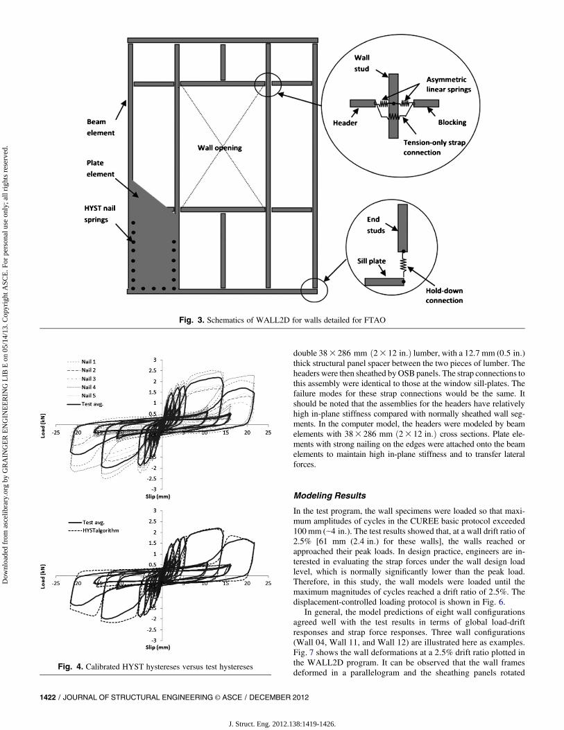
TheWALL2Dprogram, compiled in Intel Visual Fortran 10.1 (Intel(R) Fortran Compiler Integration 10.1), was developed tomodel thebehavior of wood shear walls subjected to monotonic or cyclic loads(Li et al. 2012). Its original version consists of linear elastic beamelements for framing members, orthotropic plate elements forsheathing panels, linear springs for framing connections, andnonlinear-oriented springs for panel-frame nailed connections. Themodel does not consider the rotational stiffness of framing con-nections. A special feature about this model is the implementation ofa mechanics-based protocol-independent algorithm called HYST,originally developed by Foschi (2000), to account for the nonlinearbehavior of nailed connections. The HYST algorithm is able to fullyaddress strength/stiffness degradation and the pinching effect in thenailed connections. In this study, the nonlinearity in the tension-onlystrap connections around openings and hold-down connections wasconsidered by nonlinear tension springs. Additionally, a type ofasymmetric linear spring with higher compression stiffness butlower tension stiffness has also been introduced to consider therelatively high contact stiffness between header/blocking and wallstuds when they are pushing against each other. Fig. 3 illustrates themodified WALL2D model used in this study.
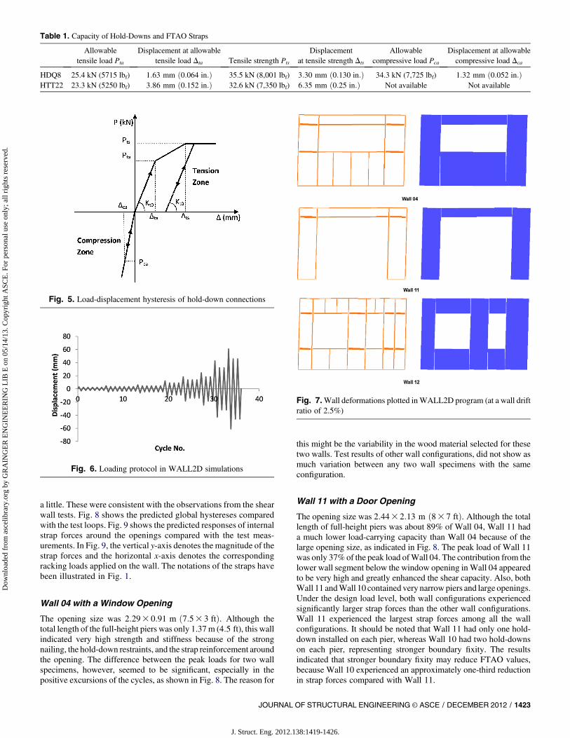
Because nailed connections usually govern the shear behavior ofstructural panel-sheathed walls, nailed connection tests were alsoconducted to calibrate the HYST parameters. In the nail connectiontest, a 10d common nail was used to connect a piece of 383 89 mmDouglas fir lumber and a piece of OSB panel used in the wallspecimens. A total of 15 specimens were tested under monotonicloading and cyclic loading, respectively. Fig. 4 shows the nail load-slip hystereses tested under the CUREE basic protocol (ISO 2003).The major failure mode was the nail pull-through. The averageenvelope curve from five replicates was used to calibrate the HYST
Fig. 1. Wall specimen and notations of FTAO straps
1420 / JOURNAL OF STRUCTURAL ENGINEERING © ASCE / DECEMBER 2012
J. Struct. Eng. 2012.138:1419-1426.
Dow
nloa
ded
from
asc
elib
rary
.org
by
GR
AIN
GE
R E
NG
INE
ER
ING
LIB
E o
n 05
/14/
13. C
opyr
ight
ASC
E. F
or p
erso
nal u
se o
nly;
all
righ
ts r
eser
ved.
parameters. Fig. 4 also shows that the calibrated HYST hystereticloops agreed very well with the test results. The calibrated HYSTwas then implemented in theWALL2Dmodel to represent the nailedconnections. The calibration procedure, as well as the calibratedHYST parameters, can be found in work by Li et al. (2012).
According to the Canadian standard (CSA 2005), modulus ofelasticity (MOE) of the Douglas-fir framing members was assumedto be 10 GPa (1,450 ksi); the Young’s moduli Ex and Ey for the OSBsheathing were assumed to be 3.5 (508 ksi) and 2.0 GPa (290 ksi)along themajor axis and the perpendicular axis, respectively; and theshear-through-thickness rigidity Gxy was assumed to be 0.5 GPa(73 ksi). Poisson ratios gxy and gyx of the OSB panels were assumedto be 0.13 and 0.23 (Thomas 2003).
In the wall specimens, HDQ8 hold-downs were connectedwith double 383 89 mm ð23 4 in:Þ end studs via 20-SDS screws
[6:353 76 mm ð1=43 3 in:Þ], and HTT22 tension ties were fas-tened on the top of the OSB panels connecting the underlyingheaders and blocking members via 32 16d sinker nails[3:763 82:6 mm ð0:1483 31=4 in:Þ. Table 1 shows the allowabletension/compression loads and strength of the HDQ8 hold-downsand HTT22 tension ties (Simpson Strong-Tie 2010). In the wallmodel, the envelope curve of tension force-displacement relation-ship for hold-down connections was defined as a trilinear curve,as shown in Fig. 5. Under reversed cyclic loading, the load-displacement hysteresis was assumed to follow elastoplasticrules, and the unloading stiffness is the initial stiffnessKt0, defined asthe ratio of the allowable tension load Pta to the correspondingdisplacement Dta. The same rule of hysteresis is also used for thetension-only HTT22 strap connections around the openings. In theshear wall test program, the headers above openings were built-up
Fig. 2. Configurations of shear walls detailed for FTAO
JOURNAL OF STRUCTURAL ENGINEERING © ASCE / DECEMBER 2012 / 1421
J. Struct. Eng. 2012.138:1419-1426.
Dow
nloa
ded
from
asc
elib
rary
.org
by
GR
AIN
GE
R E
NG
INE
ER
ING
LIB
E o
n 05
/14/
13. C
opyr
ight
ASC
E. F
or p
erso
nal u
se o
nly;
all
righ
ts r
eser
ved.
double 383 286 mm ð23 12 in:Þ lumber, with a 12.7 mm (0:5 in:)thick structural panel spacer between the two pieces of lumber. Theheaders were then sheathed byOSB panels. The strap connections tothis assembly were identical to those at the window sill-plates. Thefailure modes for these strap connections would be the same. Itshould be noted that the assemblies for the headers have relativelyhigh in-plane stiffness compared with normally sheathed wall seg-ments. In the computer model, the headers were modeled by beamelements with 383 286 mm ð23 12 in:Þ cross sections. Plate ele-ments with strong nailing on the edges were attached onto the beamelements to maintain high in-plane stiffness and to transfer lateralforces.
Modeling Results
In the test program, the wall specimens were loaded so that maxi-mum amplitudes of cycles in the CUREE basic protocol exceeded100mm (
e
4 in:). The test results showed that, at a wall drift ratio of2.5% [61 mm (2:4 in:) for these walls], the walls reached orapproached their peak loads. In design practice, engineers are in-terested in evaluating the strap forces under the wall design loadlevel, which is normally significantly lower than the peak load.Therefore, in this study, the wall models were loaded until themaximum magnitudes of cycles reached a drift ratio of 2.5%. Thedisplacement-controlled loading protocol is shown in Fig. 6.
In general, the model predictions of eight wall configurationsagreed well with the test results in terms of global load-driftresponses and strap force responses. Three wall configurations(Wall 04, Wall 11, and Wall 12) are illustrated here as examples.Fig. 7 shows the wall deformations at a 2.5% drift ratio plotted inthe WALL2D program. It can be observed that the wall framesdeformed in a parallelogram and the sheathing panels rotated
Fig. 3. Schematics of WALL2D for walls detailed for FTAO
Fig. 4. Calibrated HYST hystereses versus test hystereses
1422 / JOURNAL OF STRUCTURAL ENGINEERING © ASCE / DECEMBER 2012
J. Struct. Eng. 2012.138:1419-1426.
Dow
nloa
ded
from
asc
elib
rary
.org
by
GR
AIN
GE
R E
NG
INE
ER
ING
LIB
E o
n 05
/14/
13. C
opyr
ight
ASC
E. F
or p
erso
nal u
se o
nly;
all
righ
ts r
eser
ved.
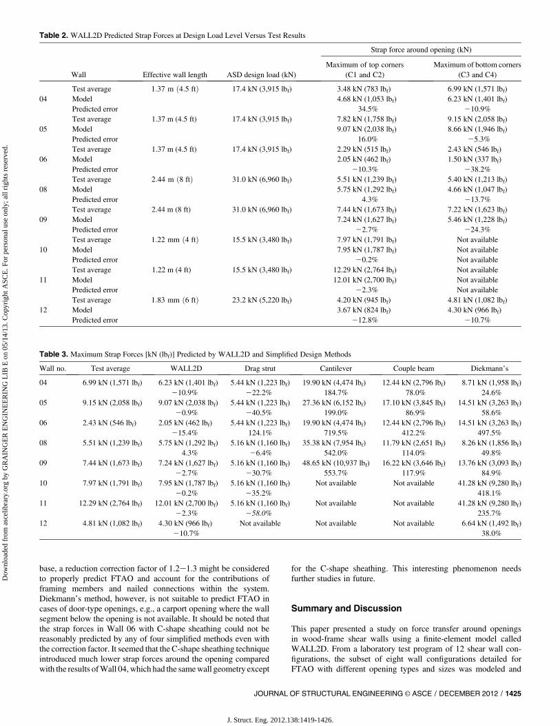
a little. These were consistent with the observations from the shearwall tests. Fig. 8 shows the predicted global hystereses comparedwith the test loops. Fig. 9 shows the predicted responses of internalstrap forces around the openings compared with the test meas-urements. In Fig. 9, the vertical y-axis denotes the magnitude of thestrap forces and the horizontal x-axis denotes the correspondingracking loads applied on the wall. The notations of the straps havebeen illustrated in Fig. 1.
Wall 04 with a Window Opening
The opening size was 2:293 0:91 m ð7:53 3 ftÞ. Although thetotal length of the full-height piers was only 1.37m (4:5 ft), this wallindicated very high strength and stiffness because of the strongnailing, the hold-down restraints, and the strap reinforcement aroundthe opening. The difference between the peak loads for two wallspecimens, however, seemed to be significant, especially in thepositive excursions of the cycles, as shown in Fig. 8. The reason for
this might be the variability in the wood material selected for thesetwo walls. Test results of other wall configurations, did not show asmuch variation between any two wall specimens with the sameconfiguration.
Wall 11 with a Door Opening
The opening size was 2:443 2:13 m ð83 7 ftÞ. Although the totallength of full-height piers was about 89% of Wall 04, Wall 11 hada much lower load-carrying capacity than Wall 04 because of thelarge opening size, as indicated in Fig. 8. The peak load of Wall 11was only 37%of the peak load ofWall 04. The contribution from thelower wall segment below the window opening inWall 04 appearedto be very high and greatly enhanced the shear capacity. Also, bothWall 11 andWall 10 contained very narrowpiers and large openings.Under the design load level, both wall configurations experiencedsignificantly larger strap forces than the other wall configurations.Wall 11 experienced the largest strap forces among all the wallconfigurations. It should be noted that Wall 11 had only one hold-down installed on each pier, whereas Wall 10 had two hold-downson each pier, representing stronger boundary fixity. The resultsindicated that stronger boundary fixity may reduce FTAO values,because Wall 10 experienced an approximately one-third reductionin strap forces compared with Wall 11.
Table 1. Capacity of Hold-Downs and FTAO Straps
Allowabletensile load Pta
Displacement at allowabletensile load Dta Tensile strength Pts
Displacementat tensile strength Dts
Allowablecompressive load Pca
Displacement at allowablecompressive load Dca
HDQ8 25.4 kN (5715 lbf) 1:63 mm ð0:064 in:Þ 35.5 kN (8,001 lbf) 3:30 mm ð0:130 in:Þ 34.3 kN (7,725 lbf) 1:32 mm ð0:052 in:ÞHTT22 23.3 kN (5250 lbf) 3:86 mm ð0:152 in:Þ 32.6 kN (7,350 lbf) 6:35 mm ð0:25 in:Þ Not available Not available
Fig. 5. Load-displacement hysteresis of hold-down connections
Fig. 6. Loading protocol in WALL2D simulations
Fig. 7.Wall deformations plotted inWALL2D program (at a wall driftratio of 2.5%)
JOURNAL OF STRUCTURAL ENGINEERING © ASCE / DECEMBER 2012 / 1423
J. Struct. Eng. 2012.138:1419-1426.
Dow
nloa
ded
from
asc
elib
rary
.org
by
GR
AIN
GE
R E
NG
INE
ER
ING
LIB
E o
n 05
/14/
13. C
opyr
ight
ASC
E. F
or p
erso
nal u
se o
nly;
all
righ
ts r
eser
ved.
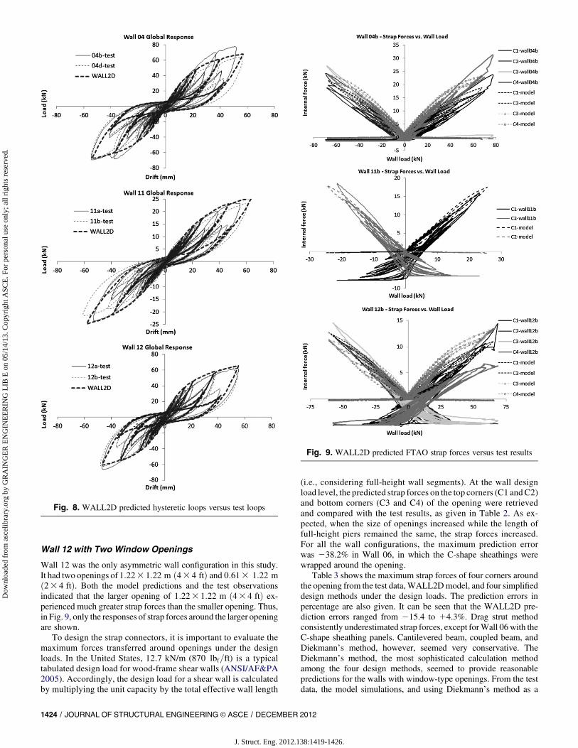
Wall 12 with Two Window Openings
Wall 12 was the only asymmetric wall configuration in this study.It had two openings of 1:223 1:22 m ð43 4 ftÞ and 0:613 1:22 mð23 4 ftÞ. Both the model predictions and the test observationsindicated that the larger opening of 1:223 1:22 m ð43 4 ftÞ ex-perienced much greater strap forces than the smaller opening. Thus,in Fig. 9, only the responses of strap forces around the larger openingare shown.
To design the strap connectors, it is important to evaluate themaximum forces transferred around openings under the designloads. In the United States, 12.7 kN/m (870 lbf=ft) is a typicaltabulated design load for wood-frame shear walls (ANSI/AF&PA2005). Accordingly, the design load for a shear wall is calculatedby multiplying the unit capacity by the total effective wall length
(i.e., considering full-height wall segments). At the wall designload level, the predicted strap forces on the top corners (C1 andC2)and bottom corners (C3 and C4) of the opening were retrievedand compared with the test results, as given in Table 2. As ex-pected, when the size of openings increased while the length offull-height piers remained the same, the strap forces increased.For all the wall configurations, the maximum prediction errorwas 238.2% in Wall 06, in which the C-shape sheathings werewrapped around the opening.
Table 3 shows the maximum strap forces of four corners aroundthe opening from the test data,WALL2Dmodel, and four simplifieddesign methods under the design loads. The prediction errors inpercentage are also given. It can be seen that the WALL2D pre-diction errors ranged from 215.4 to 14.3%. Drag strut methodconsistently underestimated strap forces, except forWall 06with theC-shape sheathing panels. Cantilevered beam, coupled beam, andDiekmann’s method, however, seemed very conservative. TheDiekmann’s method, the most sophisticated calculation methodamong the four design methods, seemed to provide reasonablepredictions for the walls with window-type openings. From the testdata, the model simulations, and using Diekmann’s method as a
Fig. 8. WALL2D predicted hysteretic loops versus test loops
Fig. 9. WALL2D predicted FTAO strap forces versus test results
1424 / JOURNAL OF STRUCTURAL ENGINEERING © ASCE / DECEMBER 2012
J. Struct. Eng. 2012.138:1419-1426.
Dow
nloa
ded
from
asc
elib
rary
.org
by
GR
AIN
GE
R E
NG
INE
ER
ING
LIB
E o
n 05
/14/
13. C
opyr
ight
ASC
E. F
or p
erso
nal u
se o
nly;
all
righ
ts r
eser
ved.
base, a reduction correction factor of 1.2e1.3 might be consideredto properly predict FTAO and account for the contributions offraming members and nailed connections within the system.Diekmann’s method, however, is not suitable to predict FTAO incases of door-type openings, e.g., a carport opening where the wallsegment below the opening is not available. It should be noted thatthe strap forces in Wall 06 with C-shape sheathing could not bereasonably predicted by any of four simplified methods even withthe correction factor. It seemed that the C-shape sheathing techniqueintroduced much lower strap forces around the opening comparedwith the results ofWall 04,which had the samewall geometry except
for the C-shape sheathing. This interesting phenomenon needsfurther studies in future.
Summary and Discussion
This paper presented a study on force transfer around openingsin wood-frame shear walls using a finite-element model calledWALL2D. From a laboratory test program of 12 shear wall con-figurations, the subset of eight wall configurations detailed forFTAO with different opening types and sizes was modeled and
Table 2. WALL2D Predicted Strap Forces at Design Load Level Versus Test Results
Wall Effective wall length ASD design load (kN)
Strap force around opening (kN)
Maximum of top corners(C1 and C2)
Maximum of bottom corners(C3 and C4)
Test average 1:37 m ð4:5 ftÞ 17.4 kN (3,915 lbf) 3.48 kN (783 lbf) 6.99 kN (1,571 lbf)04 Model 4.68 kN (1,053 lbf) 6.23 kN (1,401 lbf)
Predicted error 34.5% 210.9%Test average 1.37 m (4.5 ft) 17.4 kN (3,915 lbf) 7.82 kN (1,758 lbf) 9.15 kN (2,058 lbf)
05 Model 9.07 kN (2,038 lbf) 8.66 kN (1,946 lbf)Predicted error 16.0% 25.3%Test average 1.37 m (4.5 ft) 17.4 kN (3,915 lbf) 2.29 kN (515 lbf) 2.43 kN (546 lbf)
06 Model 2.05 kN (462 lbf) 1.50 kN (337 lbf)Predicted error 210.3% 238.2%Test average 2:44 m ð8 ftÞ 31.0 kN (6,960 lbf) 5.51 kN (1,239 lbf) 5.40 kN (1,213 lbf)
08 Model 5.75 kN (1,292 lbf) 4.66 kN (1,047 lbf)Predicted error 4.3% 213.7%Test average 2.44 m (8 ft) 31.0 kN (6,960 lbf) 7.44 kN (1,673 lbf) 7.22 kN (1,623 lbf)
09 Model 7.24 kN (1,627 lbf) 5.46 kN (1,228 lbf)Predicted error 22.7% 224.3%Test average 1:22 mm ð4 ftÞ 15.5 kN (3,480 lbf) 7.97 kN (1,791 lbf) Not available
10 Model 7.95 kN (1,787 lbf) Not availablePredicted error 20.2% Not availableTest average 1.22 m (4 ft) 15.5 kN (3,480 lbf) 12.29 kN (2,764 lbf) Not available
11 Model 12.01 kN (2,700 lbf) Not availablePredicted error 22.3% Not availableTest average 1:83 mm ð6 ftÞ 23.2 kN (5,220 lbf) 4.20 kN (945 lbf) 4.81 kN (1,082 lbf)
12 Model 3.67 kN (824 lbf) 4.30 kN (966 lbf)Predicted error 212.8% 210.7%
Table 3. Maximum Strap Forces [kN (lbf)] Predicted by WALL2D and Simplified Design Methods
Wall no. Test average WALL2D Drag strut Cantilever Couple beam Diekmann’s
04 6.99 kN (1,571 lbf) 6.23 kN (1,401 lbf) 5.44 kN (1,223 lbf) 19.90 kN (4,474 lbf) 12.44 kN (2,796 lbf) 8.71 kN (1,958 lbf)210.9% 222.2% 184.7% 78.0% 24.6%
05 9.15 kN (2,058 lbf) 9.07 kN (2,038 lbf) 5.44 kN (1,223 lbf) 27.36 kN (6,152 lbf) 17.10 kN (3,845 lbf) 14.51 kN (3,263 lbf)20.9% 240.5% 199.0% 86.9% 58.6%
06 2.43 kN (546 lbf) 2.05 kN (462 lbf) 5.44 kN (1,223 lbf) 19.90 kN (4,474 lbf) 12.44 kN (2,796 lbf) 14.51 kN (3,263 lbf)215.4% 124.1% 719.5% 412.2% 497.5%
08 5.51 kN (1,239 lbf) 5.75 kN (1,292 lbf) 5.16 kN (1,160 lbf) 35.38 kN (7,954 lbf) 11.79 kN (2,651 lbf) 8.26 kN (1,856 lbf)4.3% 26.4% 542.0% 114.0% 49.8%
09 7.44 kN (1,673 lbf) 7.24 kN (1,627 lbf) 5.16 kN (1,160 lbf) 48.65 kN (10,937 lbf) 16.22 kN (3,646 lbf) 13.76 kN (3,093 lbf)22.7% 230.7% 553.7% 117.9% 84.9%
10 7.97 kN (1,791 lbf) 7.95 kN (1,787 lbf) 5.16 kN (1,160 lbf) Not available Not available 41.28 kN (9,280 lbf)20.2% 235.2% 418.1%
11 12.29 kN (2,764 lbf) 12.01 kN (2,700 lbf) 5.16 kN (1,160 lbf) Not available Not available 41.28 kN (9,280 lbf)22.3% 258.0% 235.7%
12 4.81 kN (1,082 lbf) 4.30 kN (966 lbf) Not available Not available Not available 6.64 kN (1,492 lbf)210.7% 38.0%
JOURNAL OF STRUCTURAL ENGINEERING © ASCE / DECEMBER 2012 / 1425
J. Struct. Eng. 2012.138:1419-1426.
Dow
nloa
ded
from
asc
elib
rary
.org
by
GR
AIN
GE
R E
NG
INE
ER
ING
LIB
E o
n 05
/14/
13. C
opyr
ight
ASC
E. F
or p
erso
nal u
se o
nly;
all
righ
ts r
eser
ved.
analyzed. Themodel predictions of wall load-drift hystereses agreedwell with the test results when the walls were loaded cyclically up toa drift ratio of 2.5%. At the wall design load level, the model pre-dicted maximum strap forces around openings were also comparedwith test results to check the model validity. It was also found thatthe model predictions agreed much better with the test resultscompared with the four rational design methods commonly used bydesign engineers.
The current WALL2D model considers only the nonlinearitiesof panel-frame nail connections, hold-down connections, andstrap connections around openings. It does not consider the non-linearity or failure mechanism in sheathing panels and framingmembers. Therefore, it might overpredict the wall response ifthose wall elements, in some situations, would also contributesignificantly to wall nonlinearities. In fact, tearing failure of OSBsheathing panels was observed in somewall specimens when thesewalls had large deformations in the postpeak softening range.Furthermore, because framing members also play an importantrole in transferring loads among wall components in shear wallswith openings, the model simulations would be more accurate ifthe properties of framing members, such as modulus of elasticity,could be evaluated a priori by nondestructive testing. Neverthe-less, this model provides a useful tool to the study the FTAOproblem in wood-frame walls with openings. In future research,parametric studies can be further conducted to study the walls withdifferent geometries, different opening sizes, and different metalhardware for reinforcing corners of openings, providing moreinformation for rational designs of wood-frame walls detailed forFTAO.
Acknowledgments
Thiswork is part of a joint researchproject ofAPAeThe EngineeredWood Association, USDA Forest Products Laboratory and theUniversity of British Columbia. The research fund provided underthe joint venture Agreement 09-11111138-117 between APAeTheEngineered Wood Association and Forest Products Laboratory isgreatly acknowledged.
References
Andreasson S., Yasumura,M., andDaudeville, L. (2002). “Sensitivity studyof the finite element model for wood-framed shear walls.” J. Wood Sci.48(3), 171e178.
American National Standards Institute (ANSI) / American Forest & PaperAssociation (AF&PA). (2005). “Special design provisions for wind andseismic with commentary.” SDPWS-2005, Washington, DC.
ASTM. (2010). “Standard test method for cyclic (reversed) load test forshear resistance of vertical elements of the lateral force resisting systemsfor building.” E2126-10, West Conshohocken, PA.
Canadian Standard Association (CSA). (2005). “Engineering design inwood.” CSA-O86, Canadian Standard Association, Toronto.
Diekmann, E. F. (1997). “Diaphragms and shearwalls.” Wood engineeringand construction handbook, 3rdEd., K. F. Faherty andT.G.Williamson,eds., McGraw Hill, New York, 8.47e8.79.
Diekmann, E. F. (2005). “Discussion and closure of design of woodstructural panel shear walls with openings: A comparison of methods.”Wood Design Focus, 15(2), 14e15.
Doudak, G., Smith, I., Mohammad, M., and Lepper, P. (2006). “Tests andfinite element models of wood light-frame shear walls with openings.”Prog. Struct. Eng. Mater., 8(4), 165e174.
Foschi, R. O. (2000). “Modeling the hysteretic response of mechanicalconnections for wood structures.” Proc., 6th World Conference onTimber Engineering, Whistler, British Columbia, Canada.
Intel(R) Fortran Compiler Integration 10.1 [Computer software]. SantaClara, CA, Intel Corporation.
ISO. (2003). “Timber structureseJoints made with mechanical fastenerseQuasi-static reversed-cyclic testmethod.” ISO16670,Geneva, Switzerland.
Kolba, A. (2000). “The behavior of wood shear walls designed usingDiekmann’s method and subjected to static in-plane loading.” Ph.D.thesis, Marquette Univ., Milwaukee, WI.
Lam,F. (2010).“Reviewofcommonmethods toestimate force transfer aroundopenings for wood frame shear walls.” Rep. APAeThe Engineered WoodAssociation, Univ. of British Columbia, Vancouver, Canada.
Li, M., Foschi, R. O., and Lam, F. (2012). “Modeling hysteretic behavior ofwood shear walls with a protocol-independent nail connection algo-rithm.” J. Struct. Eng., 138(1), 99e108.
Martin, Z. (2005). “Design of wood structural panel shear walls with openings:A comparison of methods.” Wood Design Focus, 15(1), 18e20.
Robertson, A. A. (2004). “Comparison of methodologies for designing offorce transfer around openings in plywood shear walls.”Forest ProductsSociety Meeting onWoodframe Housing Durability and Disaster Issues.Session III: Disaster Mitigation, Forest Products Society, Las Vegas.
SAP2000 8 [Computer software]. Berkeley, CA, Computers and Structures.Simpson Strong-Tie. (2010). “Helping to build stronger, safer structures.”
Æhttp://www.strongtie.com/products/alpha_list.htmlæ (Nov. 10, 2010).Sugiyama,H. (1981). “The evaluation of shear strength of plywood sheathed
walls with openings.” Mokuzai Kogyo (Wood Industry), 36(7), 3e8.Thomas,W. H. (2003). “Poisson’s ratios of an oriented strand board.”Wood
Sci. Technol., 37(3), 259e268.Yeh, B. J., Skaggs, T., Lam, F., Li, M., Rammer, D., andWacker, J. (2011).
“Evaluations of force transfer around openings—Experimental andanalytical studies.” Rep. No. M410, APAeThe Engineered Wood As-sociation, Tacoma, WA.
1426 / JOURNAL OF STRUCTURAL ENGINEERING © ASCE / DECEMBER 2012
J. Struct. Eng. 2012.138:1419-1426.
Dow
nloa
ded
from
asc
elib
rary
.org
by
GR
AIN
GE
R E
NG
INE
ER
ING
LIB
E o
n 05
/14/
13. C
opyr
ight
ASC
E. F
or p
erso
nal u
se o
nly;
all
righ
ts r
eser
ved.