Embed Size (px)
Citation preview
Modeling
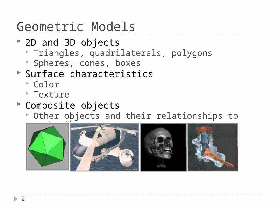
Geometric Models 2D and 3D objects
Triangles, quadrilaterals, polygons Spheres, cones, boxes
Surface characteristics Color Texture
Composite objects Other objects and their relationships to each other
2
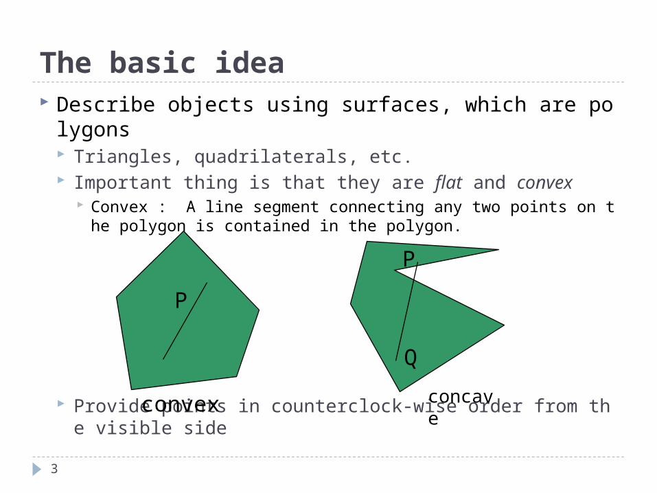
The basic idea Describe objects using surfaces, which are polygons
Triangles, quadrilaterals, etc. Important thing is that they are flat and convex
Convex : A line segment connecting any two points on the polygon is contained in the polygon.
Provide points in counterclock-wise order from the visible side
3
P
Q
P
convex concave
Outline
4
OpenGL Elementary Rendering (codes) Representation Appendix: Vector Operations *
OpenGL Elementary Rendering Geometric Primitives Building Models Managing OpenGL State
5
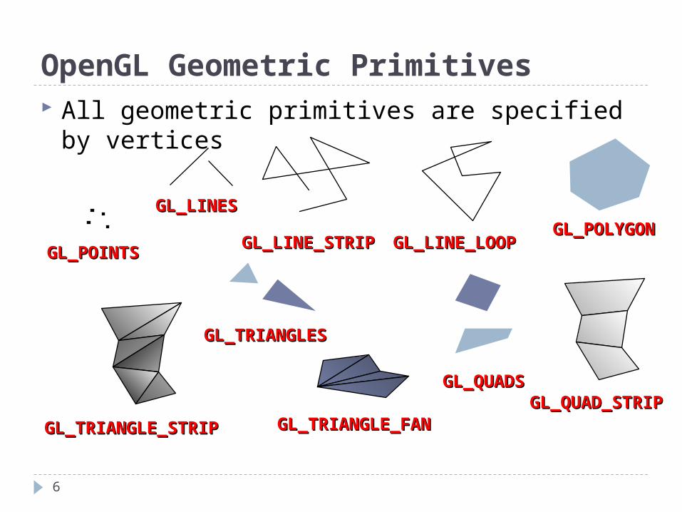
OpenGL Geometric Primitives All geometric primitives are specified by
vertices
GL_QUAD_STRIPGL_QUAD_STRIP
GL_POLYGONGL_POLYGON
GL_TRIANGLE_STRIPGL_TRIANGLE_STRIP GL_TRIANGLE_FANGL_TRIANGLE_FAN
GL_POINTSGL_POINTS
GL_LINESGL_LINES
GL_LINE_LOOPGL_LINE_LOOPGL_LINE_STRIPGL_LINE_STRIP
GL_TRIANGLESGL_TRIANGLES
GL_QUADSGL_QUADS
6
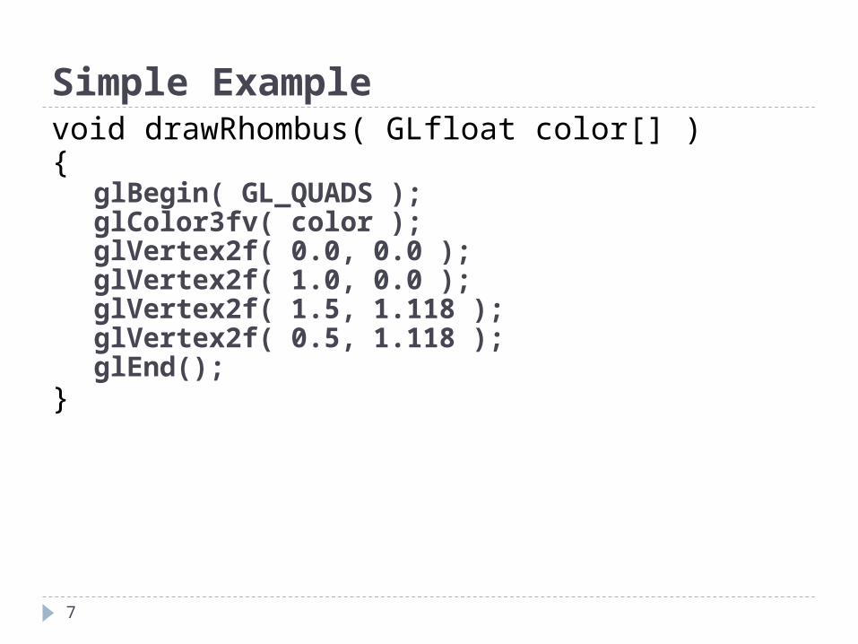
Simple Examplevoid drawRhombus( GLfloat color[] ){ glBegin( GL_QUADS ); glColor3fv( color ); glVertex2f( 0.0, 0.0 ); glVertex2f( 1.0, 0.0 ); glVertex2f( 1.5, 1.118 ); glVertex2f( 0.5, 1.118 ); glEnd();
}
7
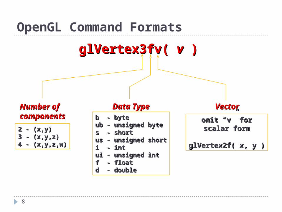
OpenGL Command Formats
glVertex3fv( glVertex3fv( vv ) )
Number ofNumber ofcomponentscomponents
2 - (x,y) 2 - (x,y) 3 - (x,y,z)3 - (x,y,z)4 - (x,y,z,w)4 - (x,y,z,w)
Data TypeData Typeb - byteb - byteub - unsigned byteub - unsigned bytes - shorts - shortus - unsigned shortus - unsigned shorti - inti - intui - unsigned intui - unsigned intf - floatf - floatd - doubled - double
VectorVector
omit omit ““vv”” for forscalar formscalar form
glVertex2f( x, y )glVertex2f( x, y )
8
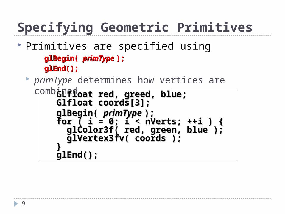
Specifying Geometric Primitives Primitives are specified using
glBegin( glBegin( primType primType ););
glEnd();glEnd();
primType determines how vertices are combined
GLfloat red, greed, blue;GLfloat red, greed, blue;Glfloat coords[3];Glfloat coords[3];glBegin( glBegin( primType primType ););for ( i = 0; i < nVerts; ++i ) { for ( i = 0; i < nVerts; ++i ) { glColor3f( red, green, blue );glColor3f( red, green, blue ); glVertex3fv( coords );glVertex3fv( coords );}}glEnd();glEnd();
9
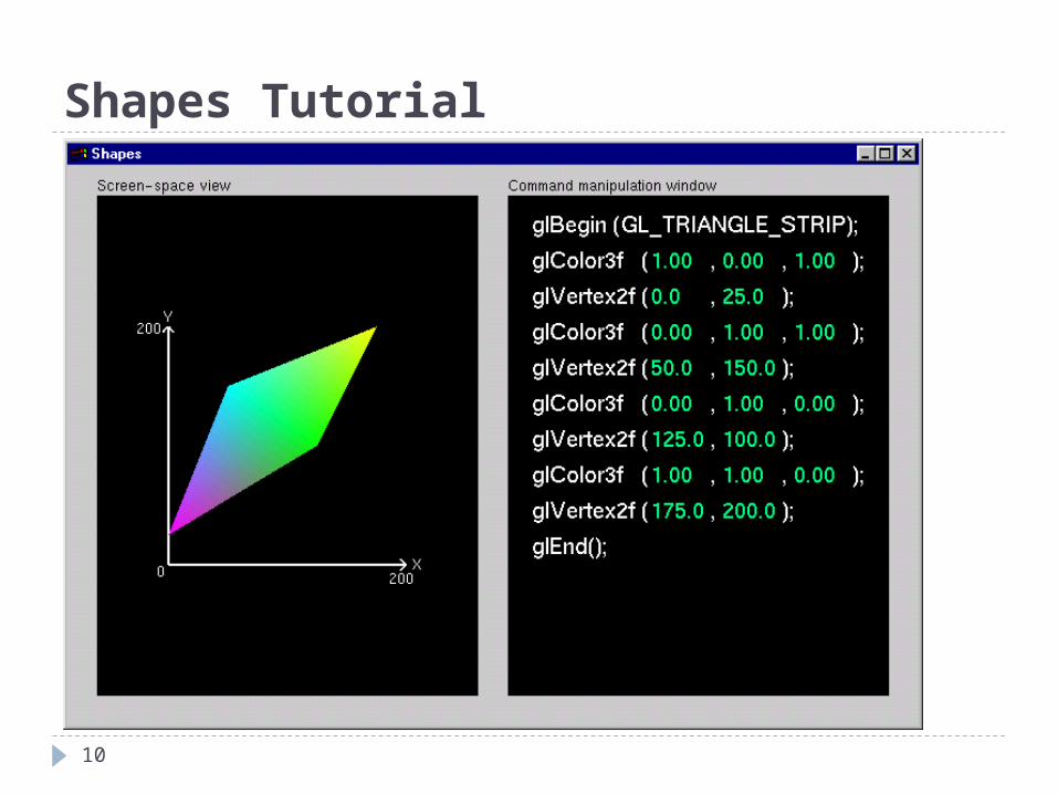
Shapes Tutorial
10
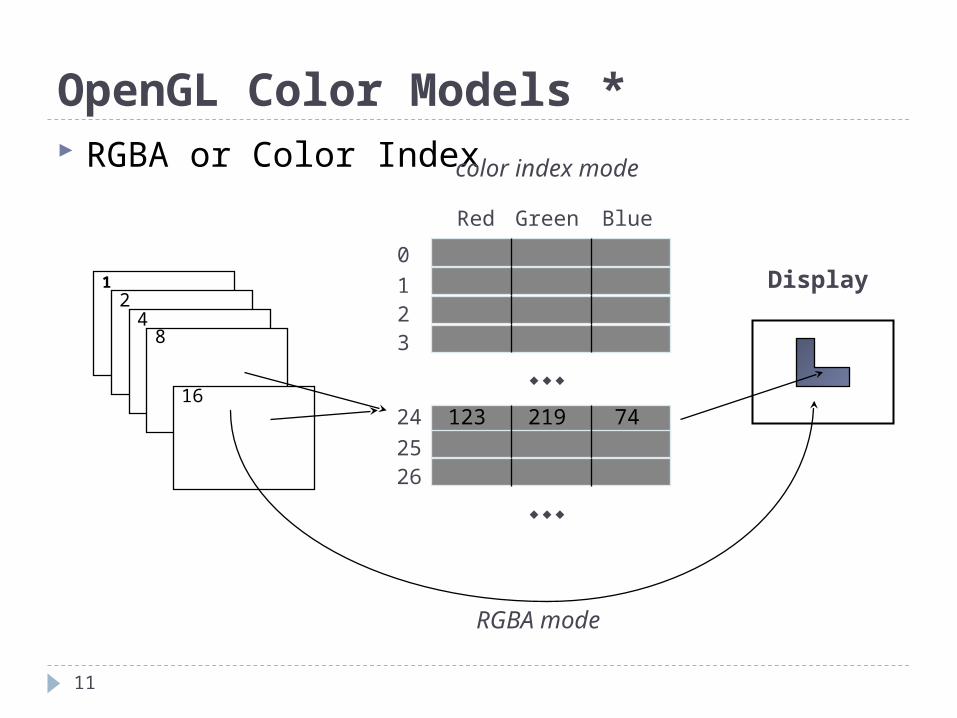
OpenGL Color Models * RGBA or Color Index color index mode
Display12
48
16
Red Green Blue
0123
24
2526
123 219 74
RGBA mode
11
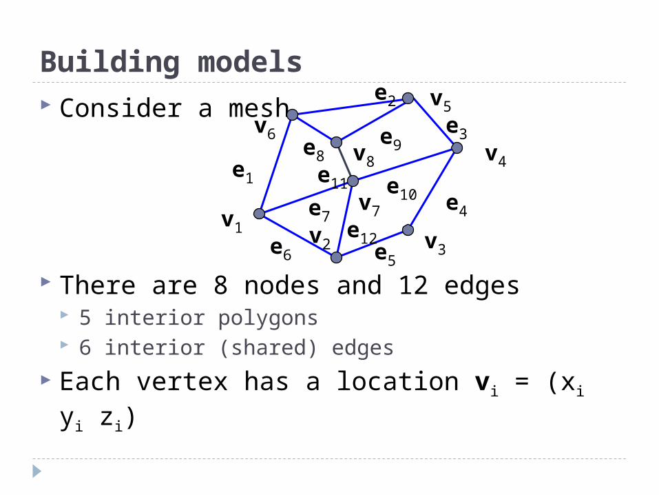
Building models Consider a mesh
There are 8 nodes and 12 edges 5 interior polygons 6 interior (shared) edges
Each vertex has a location vi = (xi yi zi)
v1 v2
v7
v6
v8
v5
v4
v3
e1
e8
e3
e2
e11
e6
e7
e10
e5
e4
e9
e12
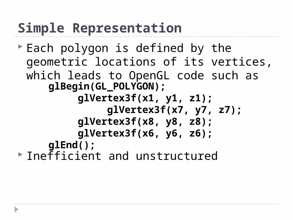
Simple Representation Each polygon is defined by the geometric
locations of its vertices, which leads to OpenGL code such as
Inefficient and unstructured
glBegin(GL_POLYGON); glVertex3f(x1, y1, z1); glVertex3f(x7, y7, z7);
glVertex3f(x8, y8, z8); glVertex3f(x6, y6, z6); glEnd();
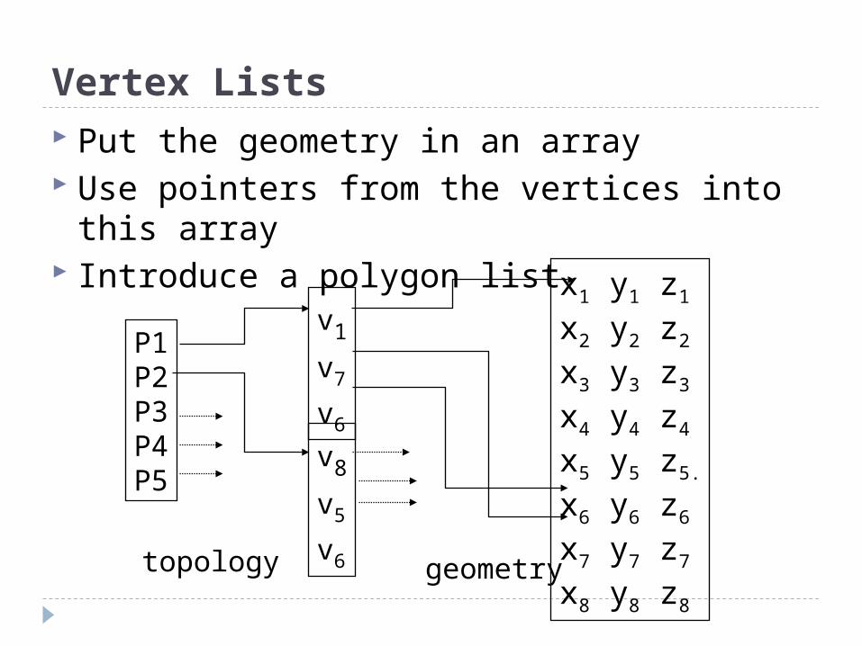
Vertex Lists Put the geometry in an array Use pointers from the vertices into this
array Introduce a polygon list x1 y1 z1
x2 y2 z2
x3 y3 z3
x4 y4 z4
x5 y5 z5.
x6 y6 z6
x7 y7 z7
x8 y8 z8
P1P2P3P4P5
v1
v7
v6
v8
v5
v6topology geometry
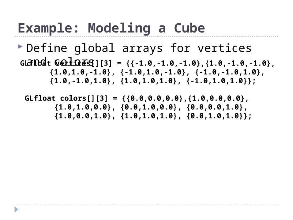
Example: Modeling a Cube Define global arrays for vertices and colorsGLfloat vertices[][3] = {{-1.0,-1.0,-1.0},{1.0,-1.0,-1.0},
{1.0,1.0,-1.0}, {-1.0,1.0,-1.0}, {-1.0,-1.0,1.0}, {1.0,-1.0,1.0}, {1.0,1.0,1.0}, {-1.0,1.0,1.0}};
GLfloat colors[][3] = {{0.0,0.0,0.0},{1.0,0.0,0.0},{1.0,1.0,0.0}, {0.0,1.0,0.0}, {0.0,0.0,1.0},
{1.0,0.0,1.0}, {1.0,1.0,1.0}, {0.0,1.0,1.0}};
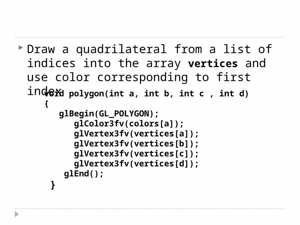
Draw a quadrilateral from a list of indices into the array vertices and use color corresponding to first index
void polygon(int a, int b, int c , int d){ glBegin(GL_POLYGON); glColor3fv(colors[a]); glVertex3fv(vertices[a]); glVertex3fv(vertices[b]); glVertex3fv(vertices[c]); glVertex3fv(vertices[d]); glEnd(); }
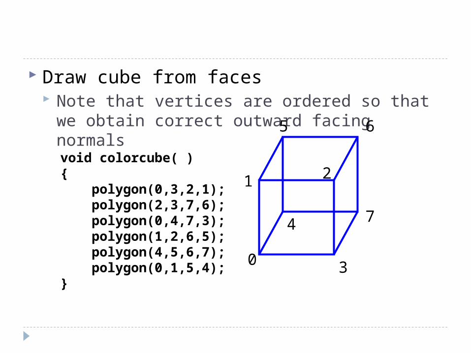
Draw cube from faces Note that vertices are ordered so that we
obtain correct outward facing normals
void colorcube( ){ polygon(0,3,2,1); polygon(2,3,7,6); polygon(0,4,7,3); polygon(1,2,6,5); polygon(4,5,6,7); polygon(0,1,5,4);}
0
5 6
2
4 7
1
3
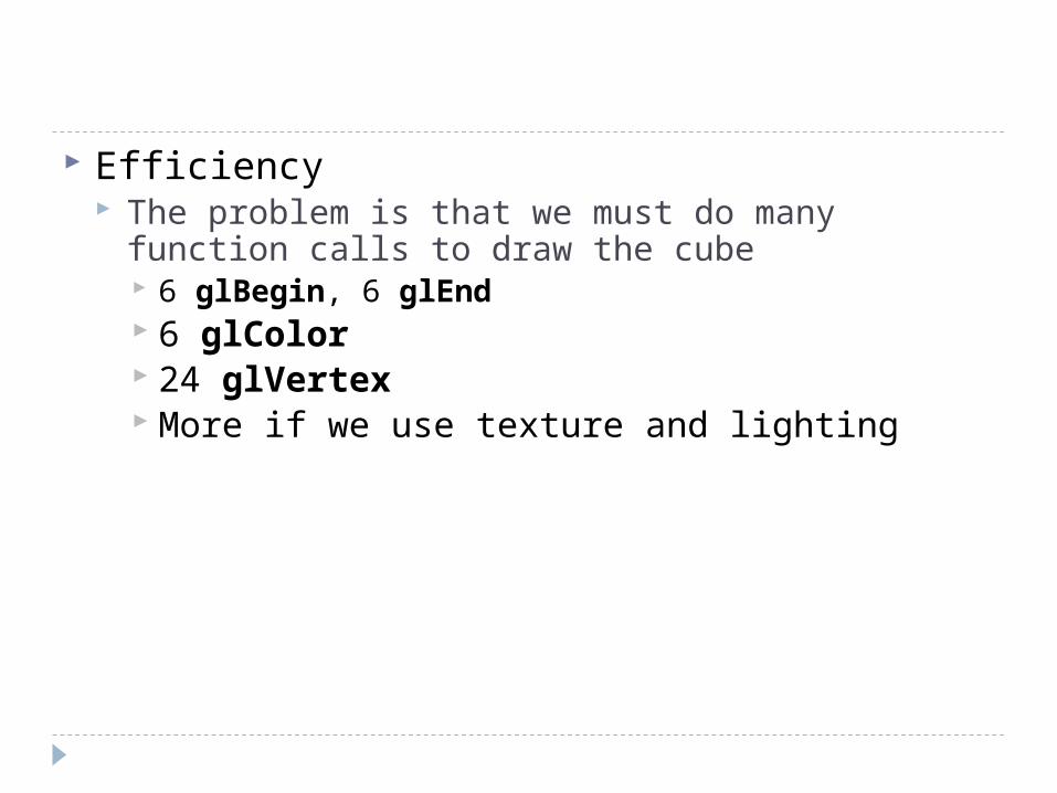
Efficiency The problem is that we must do many function
calls to draw the cube 6 glBegin, 6 glEnd 6 glColor 24 glVertex More if we use texture and lighting
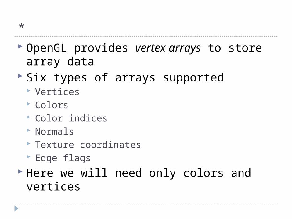
* OpenGL provides vertex arrays to store
array data Six types of arrays supported
Vertices Colors Color indices Normals Texture coordinates Edge flags
Here we will need only colors and vertices
*
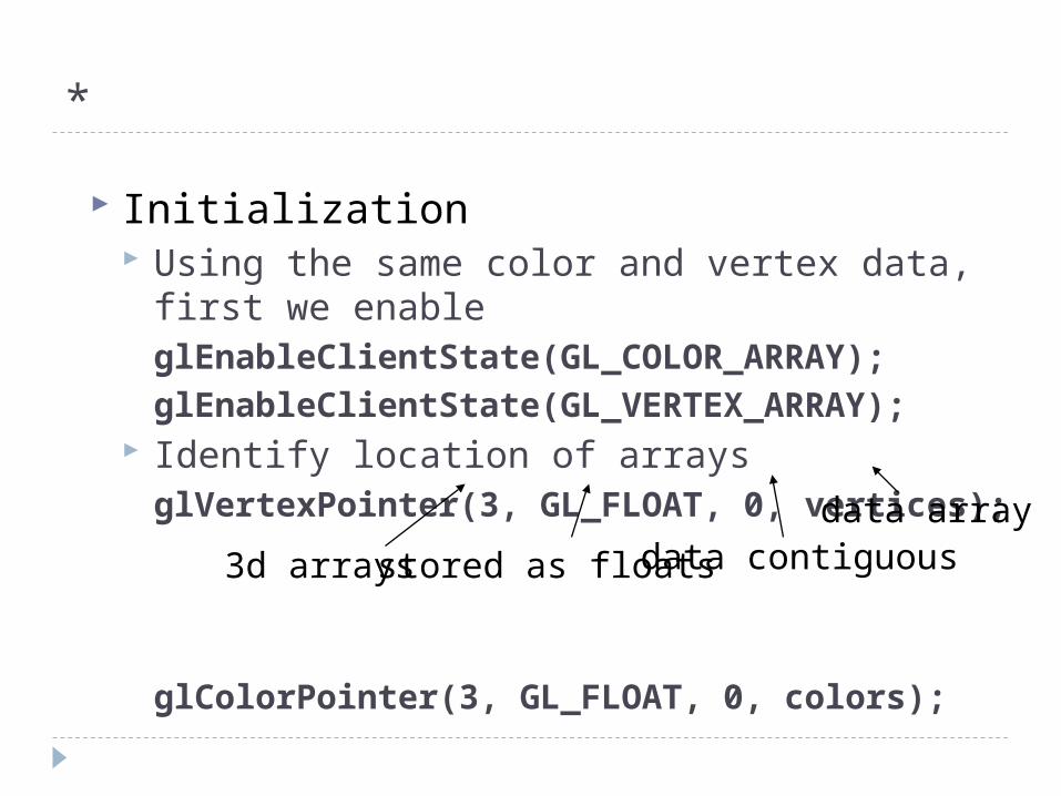
Initialization Using the same color and vertex data, first we
enableglEnableClientState(GL_COLOR_ARRAY);
glEnableClientState(GL_VERTEX_ARRAY); Identify location of arraysglVertexPointer(3, GL_FLOAT, 0, vertices);
glColorPointer(3, GL_FLOAT, 0, colors);
3d arrays stored as floats data contiguousdata array
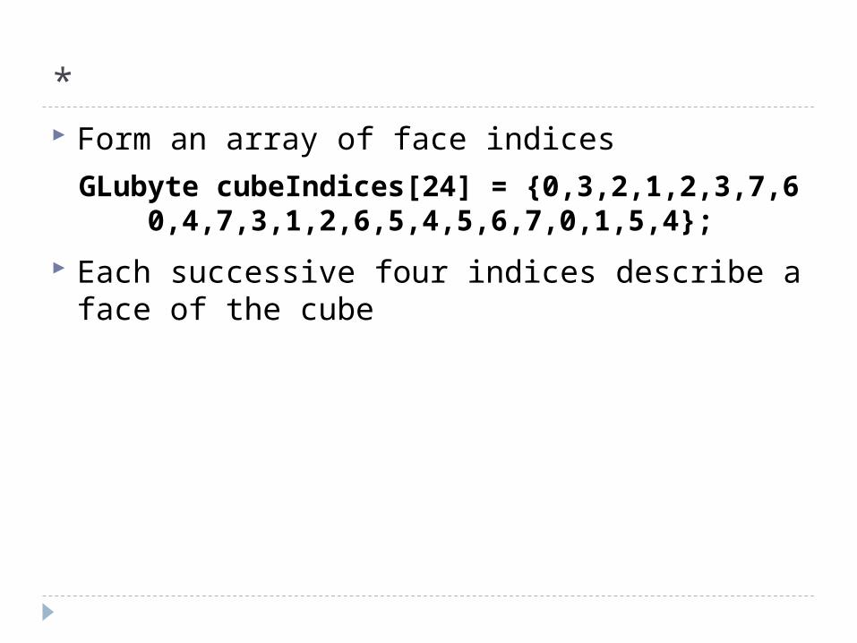
* Form an array of face indices
Each successive four indices describe a face of the cube
GLubyte cubeIndices[24] = {0,3,2,1,2,3,7,6 0,4,7,3,1,2,6,5,4,5,6,7,0,1,5,4};
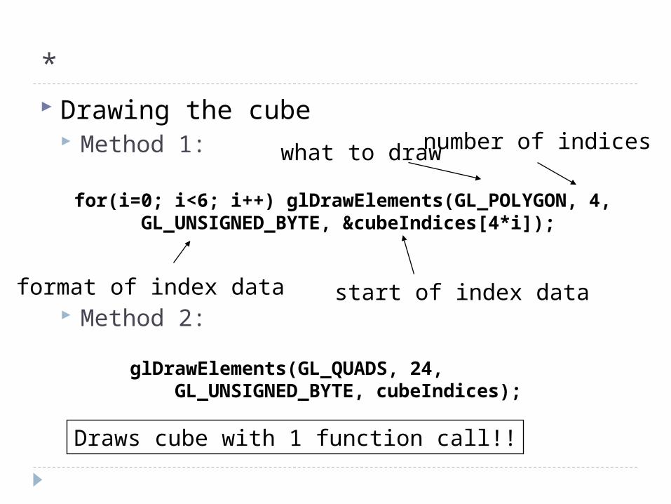
* Drawing the cube
Method 1:
Method 2:
for(i=0; i<6; i++) glDrawElements(GL_POLYGON, 4, GL_UNSIGNED_BYTE, &cubeIndices[4*i]);
format of index data start of index data
what to drawnumber of indices
glDrawElements(GL_QUADS, 24, GL_UNSIGNED_BYTE, cubeIndices);
Draws cube with 1 function call!!
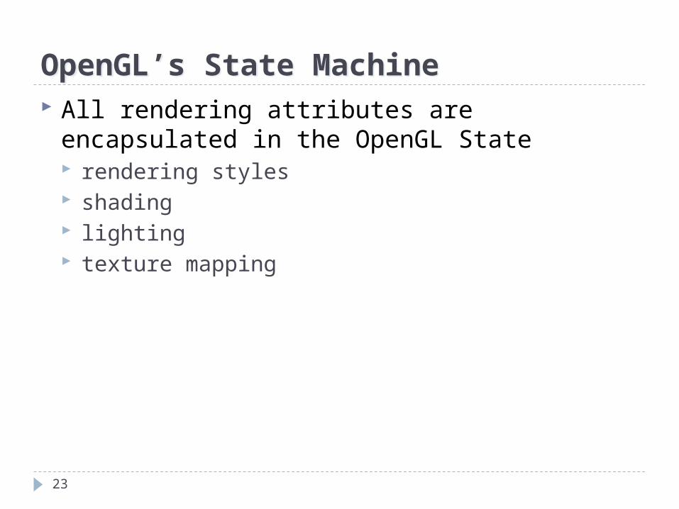
OpenGL’s State MachineOpenGL’s State Machine All rendering attributes are encapsulated in
the OpenGL State rendering styles shading lighting texture mapping
23
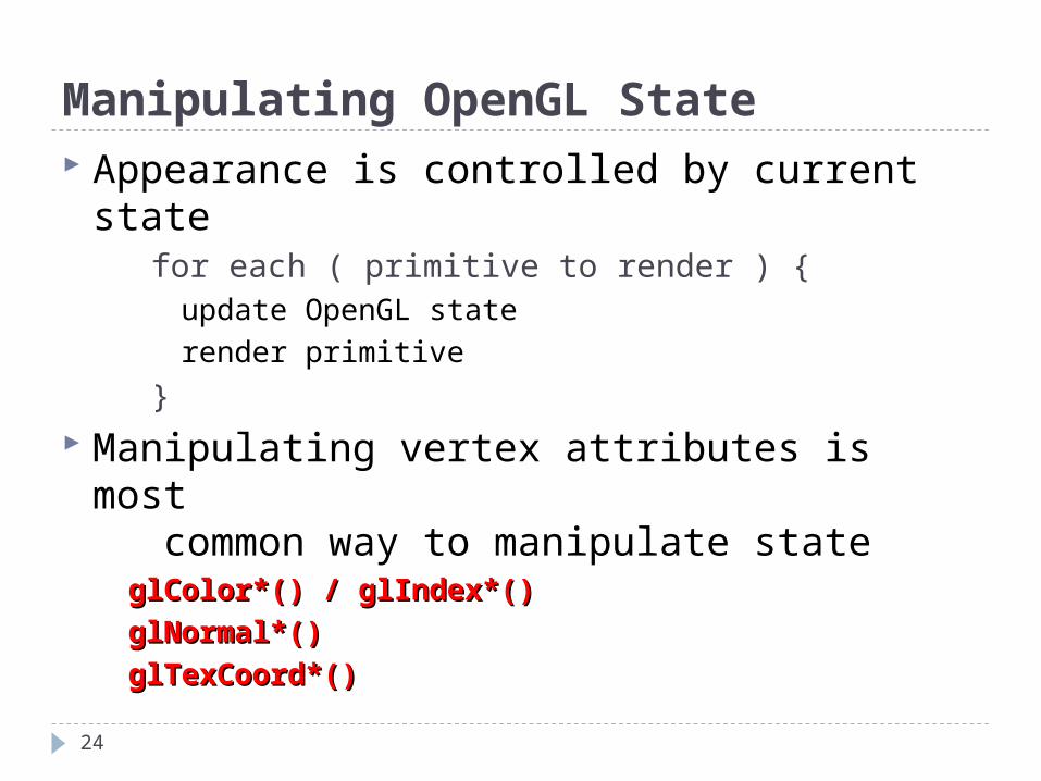
Manipulating OpenGL State Appearance is controlled by current state
for each ( primitive to render ) { update OpenGL state render primitive
} Manipulating vertex attributes is most
common way to manipulate stateglColor*() / glIndex*()glColor*() / glIndex*()
glNormal*()glNormal*()
glTexCoord*()glTexCoord*()
24
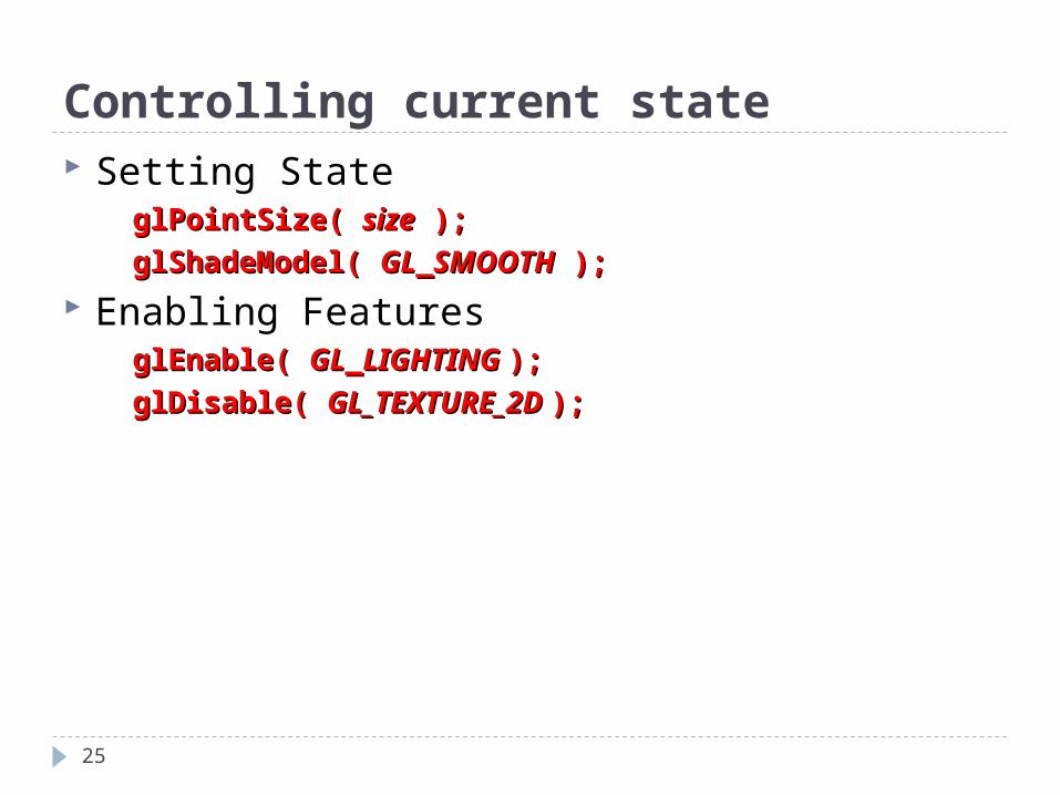
Controlling current state Setting State
glPointSize( glPointSize( sizesize ); );
glShadeModel( glShadeModel( GLGL__SMOOTHSMOOTH ); );
Enabling FeaturesglEnable( glEnable( GLGL__LIGHTING LIGHTING ););
glDisable( glDisable( GL_TEXTURE_2D GL_TEXTURE_2D ););
25
Outline
26
OpenGL Elementary Rendering (codes) Representation Appendix: Vector Operations
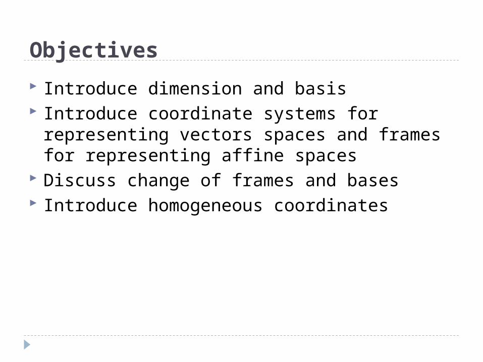
Objectives
Introduce dimension and basis Introduce coordinate systems for
representing vectors spaces and frames for representing affine spaces
Discuss change of frames and bases Introduce homogeneous coordinates
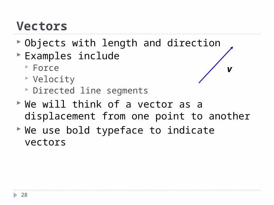
Vectors Objects with length and direction Examples include
Force Velocity Directed line segments
We will think of a vector as a displacement from one point to another
We use bold typeface to indicate vectors
v
28
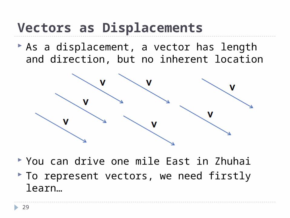
Vectors as Displacements
29
As a displacement, a vector has length and direction, but no inherent location
You can drive one mile East in Zhuhai To represent vectors, we need firstly learn…
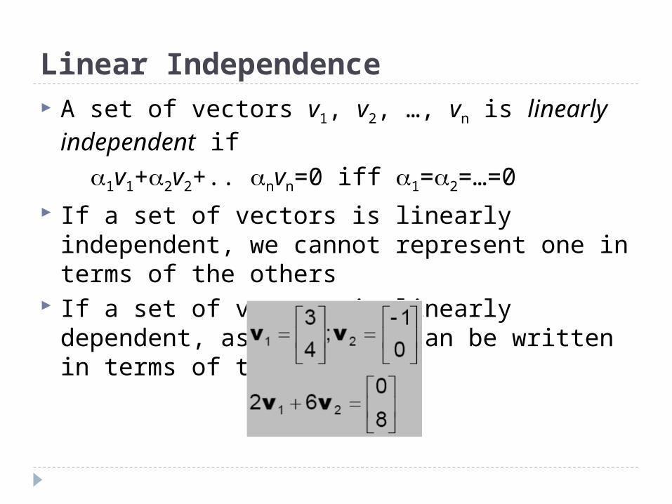
Linear Independence A set of vectors v1, v2, …, vn is linearly
independent if 1v1+2v2+.. nvn=0 iff 1=2=…=0 If a set of vectors is linearly independent, we
cannot represent one in terms of the others If a set of vectors is linearly dependent, as
least one can be written in terms of the others
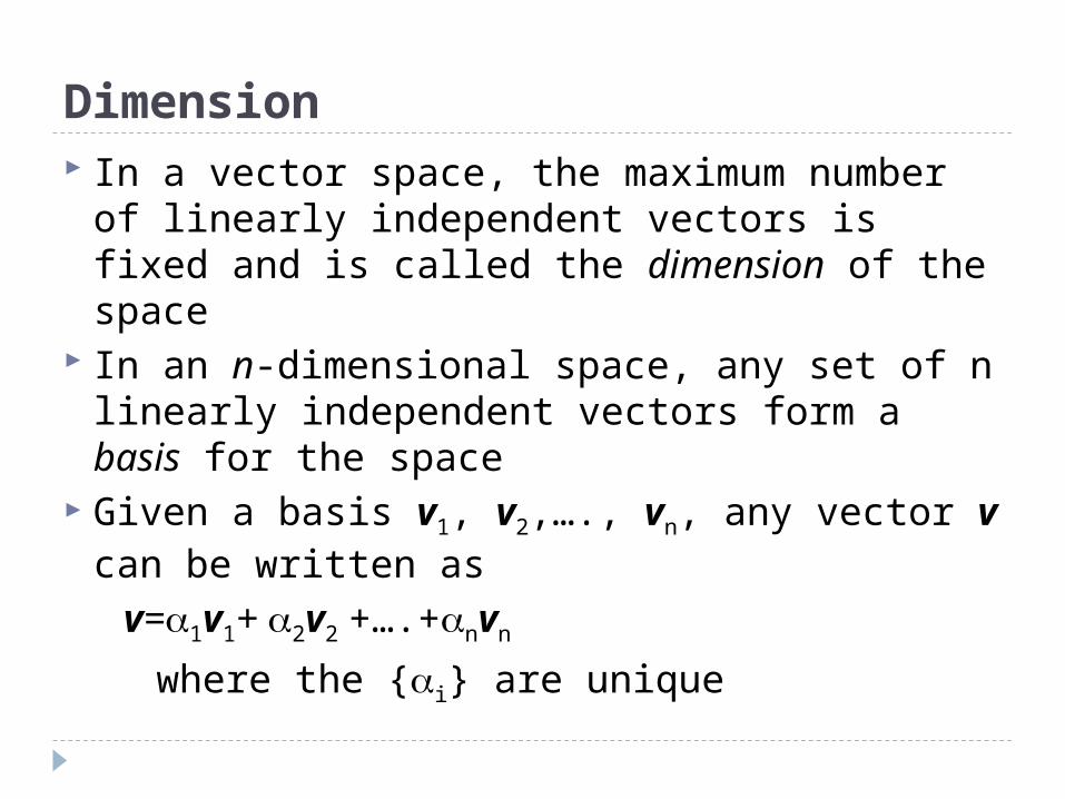
Dimension In a vector space, the maximum number of
linearly independent vectors is fixed and is called the dimension of the space
In an n-dimensional space, any set of n linearly independent vectors form a basis for the space
Given a basis v1, v2,…., vn, any vector v can be written as
v=1v1+ 2v2 +….+nvn
where the {i} are unique
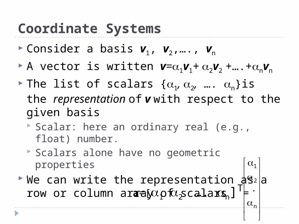
Coordinate Systems Consider a basis v1, v2,…., vn
A vector is written v=1v1+ 2v2 +….+nvn
The list of scalars {1, 2, …. n}is the representation of v with respect to the given basis Scalar: here an ordinary real (e.g., float)
number. Scalars alone have no geometric properties
We can write the representation as a row or column array of scalarsa=[1 2 …. n]
T=
n
2
1
.
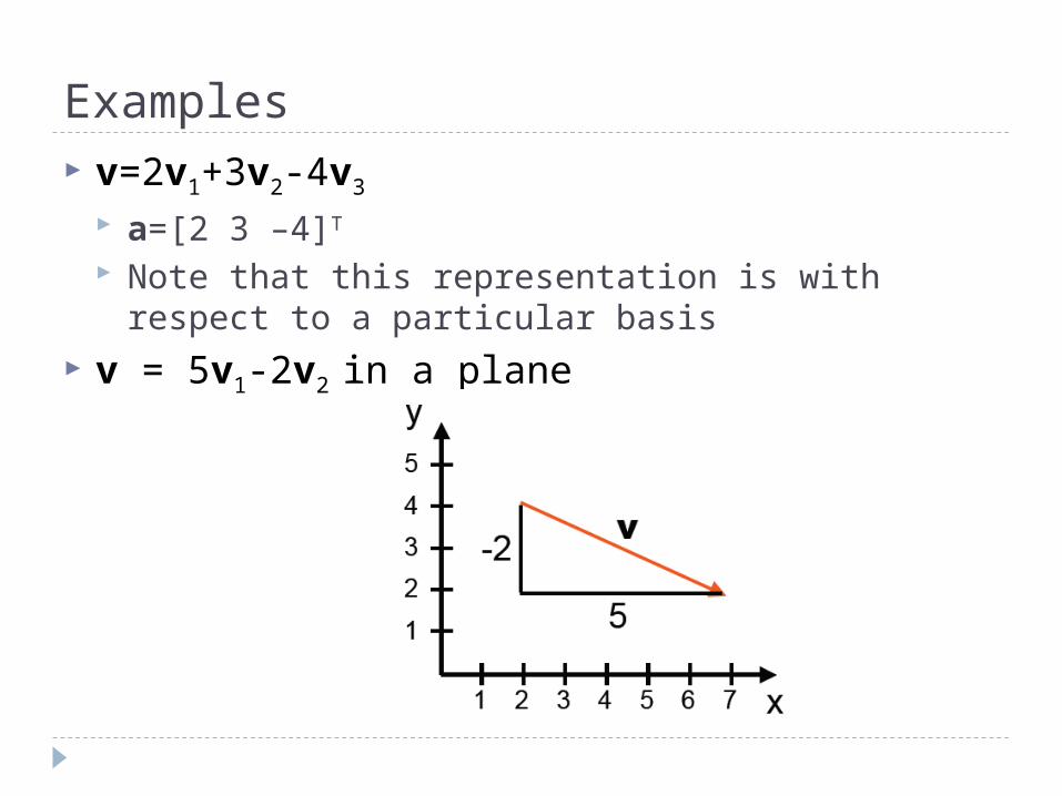
Examples v=2v1+3v2-4v3
a=[2 3 –4]T
Note that this representation is with respect to a particular basis
v = 5v1-2v2 in a plane
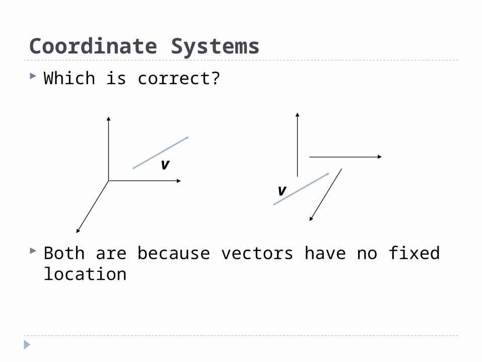
Coordinate Systems Which is correct?
Both are because vectors have no fixed location
v
v
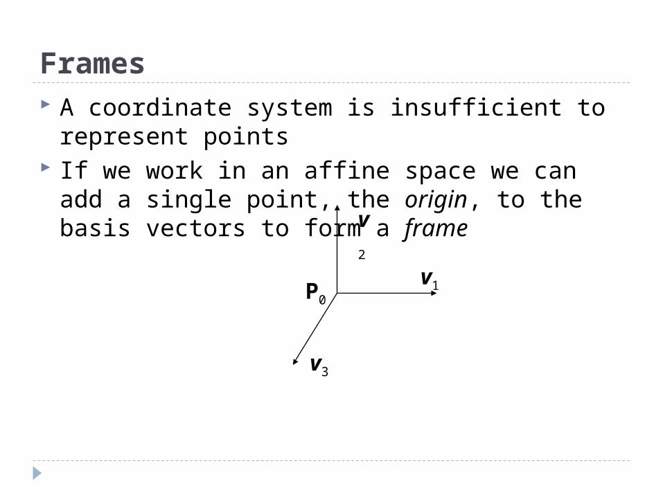
Frames A coordinate system is insufficient to
represent points If we work in an affine space we can add a
single point, the origin, to the basis vectors to form a frame
P0
v1
v2
v3
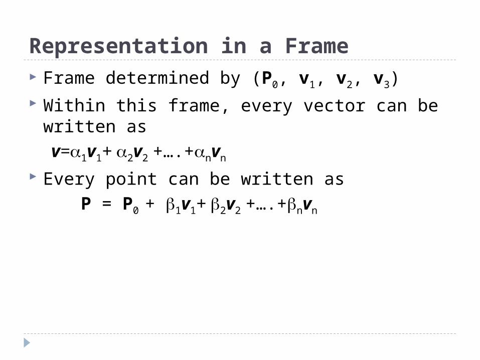
Representation in a Frame Frame determined by (P0, v1, v2, v3) Within this frame, every vector can be written
as v=1v1+ 2v2 +….+nvn
Every point can be written as P = P0 + 1v1+ 2v2 +….+nvn
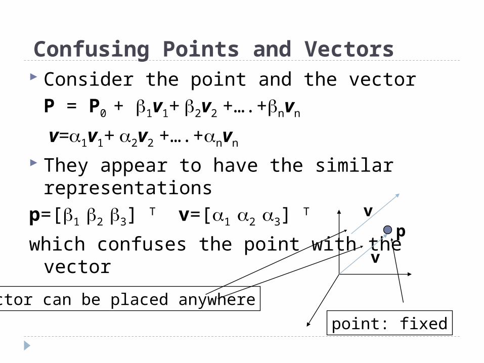
Confusing Points and Vectors Consider the point and the vector
P = P0 + 1v1+ 2v2 +….+nvn
v=1v1+ 2v2 +….+nvn
They appear to have the similar representations
p=[1 2 3] T v=[1 2 3] T
which confuses the point with the vectorv
pv
Vector can be placed anywhere
point: fixed
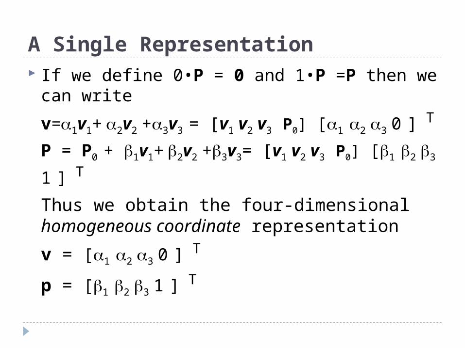
A Single Representation If we define 0•P = 0 and 1•P =P then we can
write
v=1v1+ 2v2 +3v3 = [v1 v2 v3 P0] [1 2 3 0 ] T
P = P0 + 1v1+ 2v2 +3v3= [v1 v2 v3 P0] [1 2 3 1 ] T
Thus we obtain the four-dimensional homogeneous coordinate representation
v = [1 2 3 0 ] T
p = [1 2 3 1 ] T
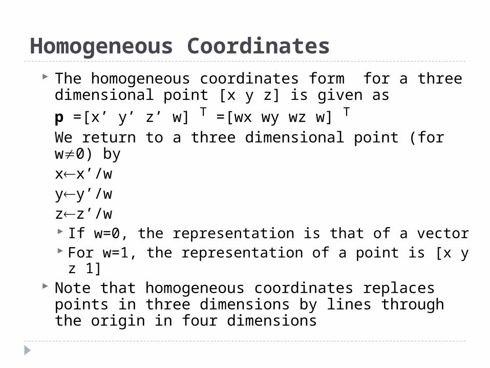
Homogeneous Coordinates The homogeneous coordinates form for a three
dimensional point [x y z] is given asp =[x’ y’ z’ w] T =[wx wy wz w] T
We return to a three dimensional point (for w0) by
xx’/wyy’/wzz’/w
If w=0, the representation is that of a vector For w=1, the representation of a point is [x y z 1]
Note that homogeneous coordinates replaces points in three dimensions by lines through the origin in four dimensions
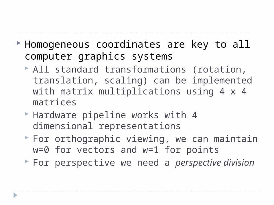
Homogeneous coordinates are key to all computer graphics systems All standard transformations (rotation,
translation, scaling) can be implemented with matrix multiplications using 4 x 4 matrices
Hardware pipeline works with 4 dimensional representations
For orthographic viewing, we can maintain w=0 for vectors and w=1 for points
For perspective we need a perspective division
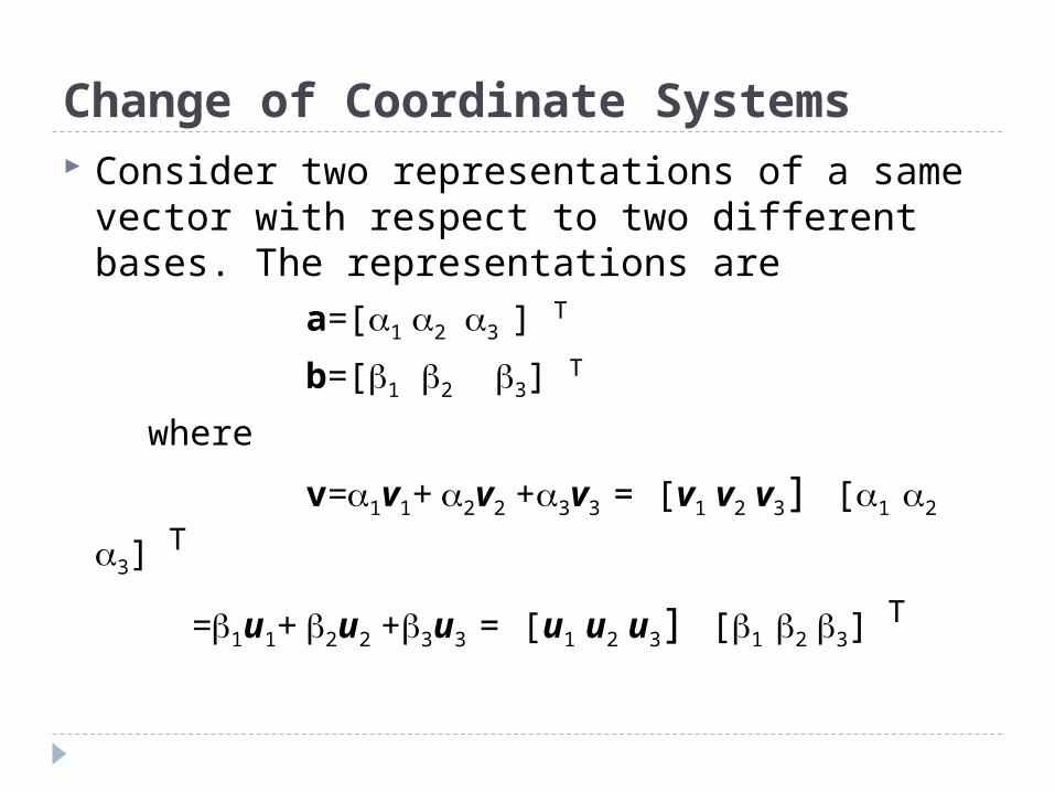
Change of Coordinate Systems Consider two representations of a same
vector with respect to two different bases. The representations are
a=[1 2 3 ] T
b=[1 2 3] T
where
v=1v1+ 2v2 +3v3 = [v1 v2 v3] [1 2 3] T
=1u1+ 2u2 +3u3 = [u1 u2 u3] [1 2 3] T
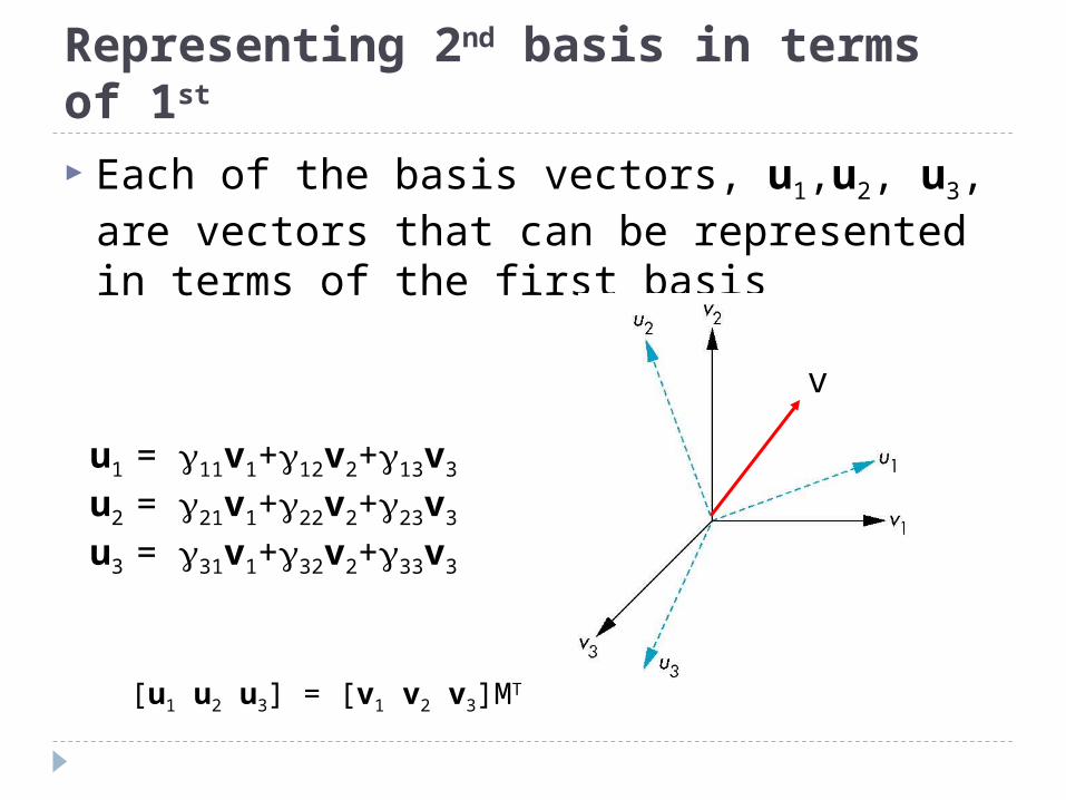
Representing 2nd basis in terms of 1st Each of the basis vectors, u1,u2, u3, are
vectors that can be represented in terms of the first basis
u1 = 11v1+12v2+13v3
u2 = 21v1+22v2+23v3
u3 = 31v1+32v2+33v3
v
[u1 u2 u3] = [v1 v2 v3]MT
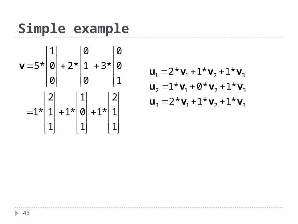
Simple example
43
1
1
2
*1
1
0
1
*1
1
1
2
*1
1
0
0
*3
0
1
0
*2
0
0
1
*5v
3213
3212
3211
*1*1*2
*1*0*1
*1*1*2
vvvu
vvvu
vvvu
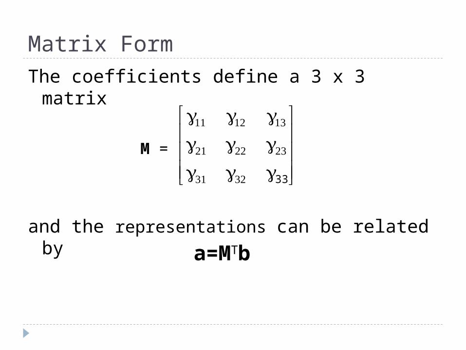
Matrix Form The coefficients define a 3 x 3 matrix
and the representations can be related by
a=MTb
33
M =

Change of Frames We can apply a similar process in
homogeneous coordinates to the representations of both points and vectors
Any point or vector can be represented in either frame
We can represent Q0, u1, u2, u3 in terms of P0, v1, v2, v3
Consider two frames:(P0, v1, v2, v3)(Q0, u1, u2, u3) P0 v1
v2
v3
Q0
u1u2
u3
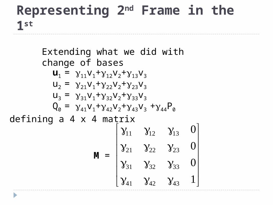
Representing 2nd Frame in the 1st
u1 = 11v1+12v2+13v3
u2 = 21v1+22v2+23v3
u3 = 31v1+32v2+33v3
Q0 = 41v1+42v2+43v3 +44P0
Extending what we did with change of bases
defining a 4 x 4 matrix
M =
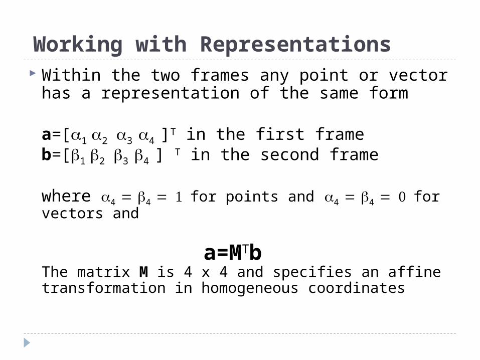
Working with Representations Within the two frames any point or vector
has a representation of the same form
a=[1 2 3 4 ]T in the first frameb=[1 2 3 4 ] T in the second frame
where 4 4 for points and 4 4 for vectors and
The matrix M is 4 x 4 and specifies an affine transformation in homogeneous coordinates
a=MTb
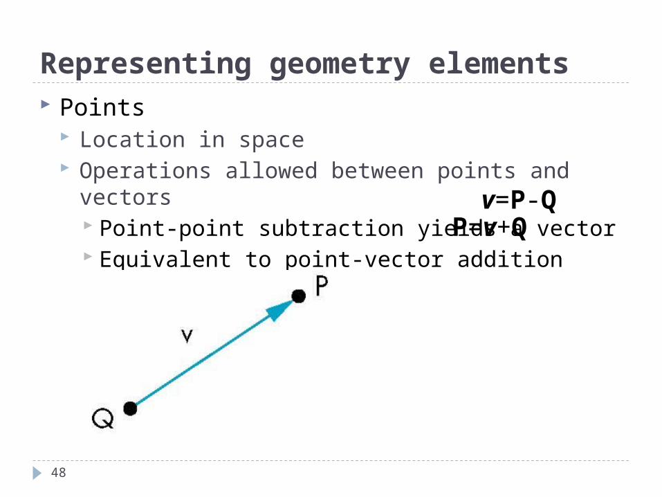
Representing geometry elements Points
Location in space Operations allowed between points and vectors
Point-point subtraction yields a vector Equivalent to point-vector addition P=v+Q
v=P-Q
48
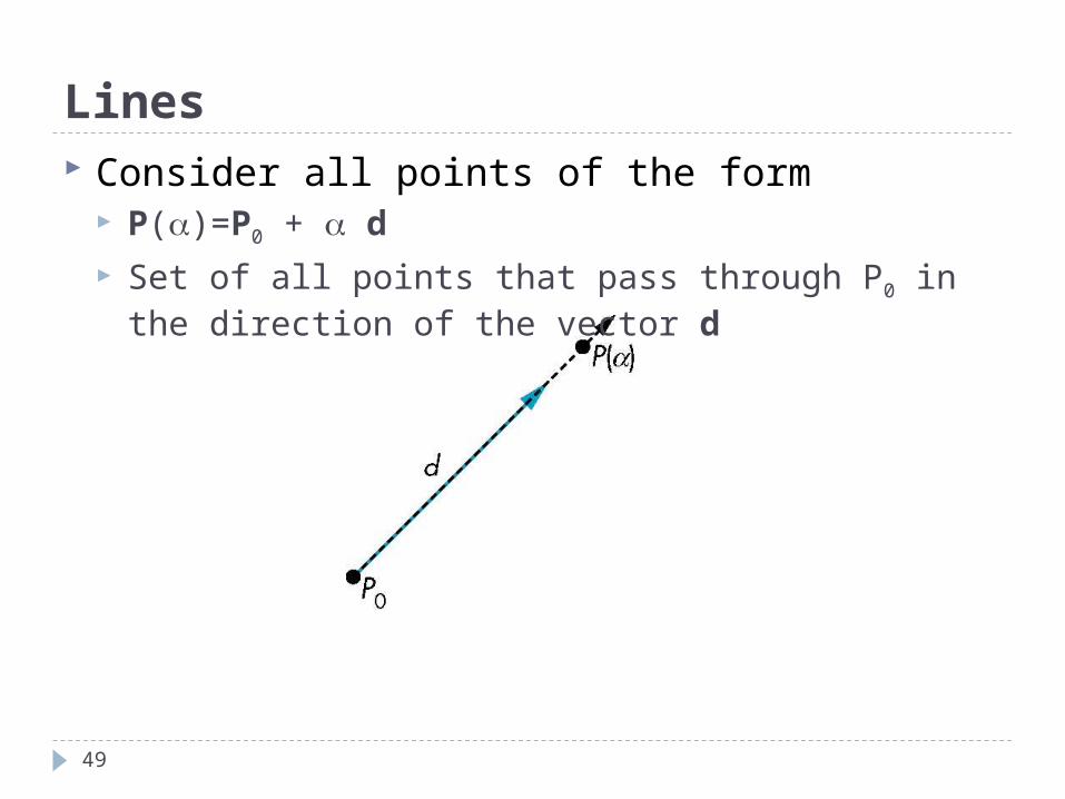
Lines Consider all points of the form
P()=P0 + d
Set of all points that pass through P0 in the direction of the vector d
49
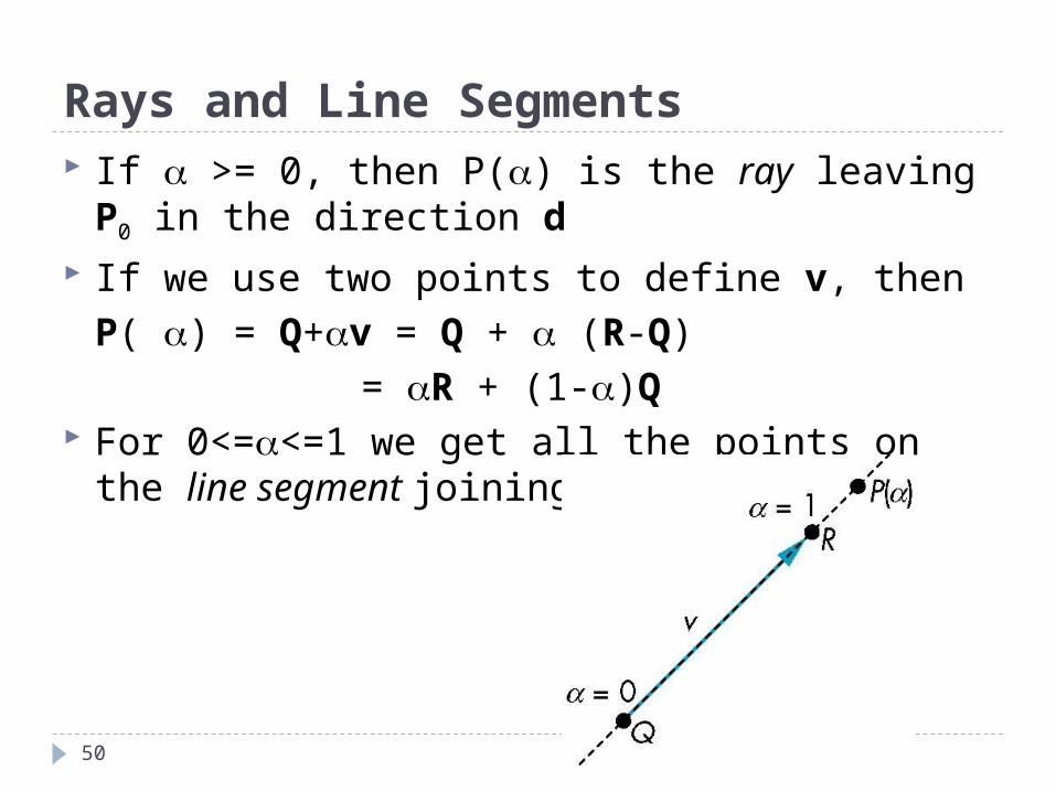
Rays and Line Segments If >= 0, then P() is the ray leaving P0 in the
direction d If we use two points to define v, then
P( ) = Q+v = Q + (R-Q)
= R + (1-)Q For 0<=<=1 we get all the points on the line
segment joining R and Q
50
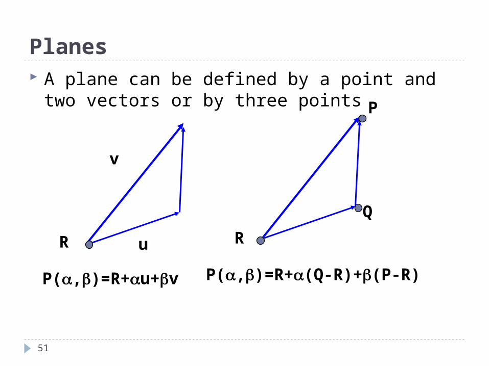
Planes A plane can be defined by a point and two
vectors or by three points
P(,)=R+u+v P(,)=R+(Q-R)+(P-R)
u
v
R
P
R
Q
51
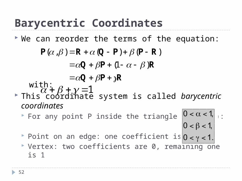
Barycentric Coordinates
52
We can reorder the terms of the equation:
with: This coordinate system is called barycentric
coordinates For any point P inside the triangle (a, b, c):
Point on an edge: one coefficient is 0 Vertex: two coefficients are 0, remaining one is 1
RPQ
RPQ
RPΡQRP
)1(
)()(),(
1
Outline
53
OpenGL Elementary Rendering Representation Appendix: Vector Operations *
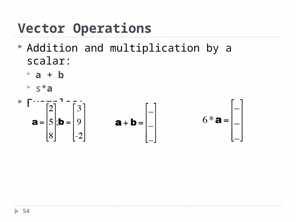
Vector Operations
54
Addition and multiplication by a scalar: a + b s*a
Examples:
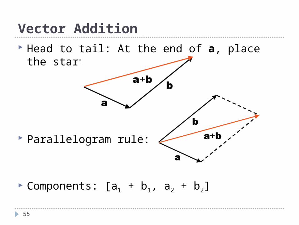
Vector Addition
55
Head to tail: At the end of a, place the start of b.
Parallelogram rule:
Components: [a1 + b1, a2 + b2]
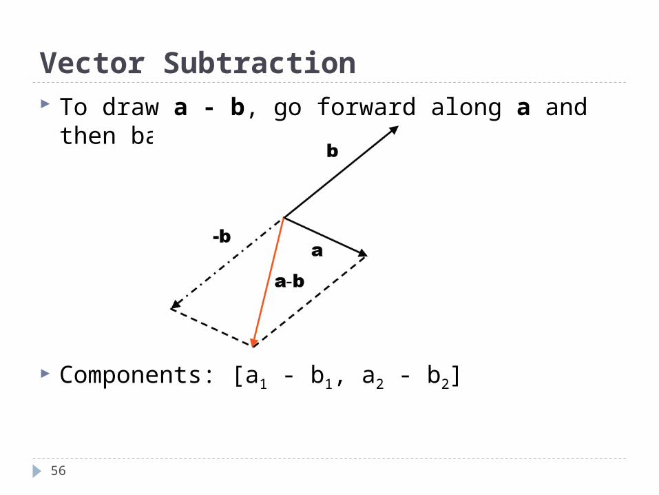
Vector Subtraction
56
To draw a - b, go forward along a and then backward along b.
Components: [a1 - b1, a2 - b2]
The Dot Product
57
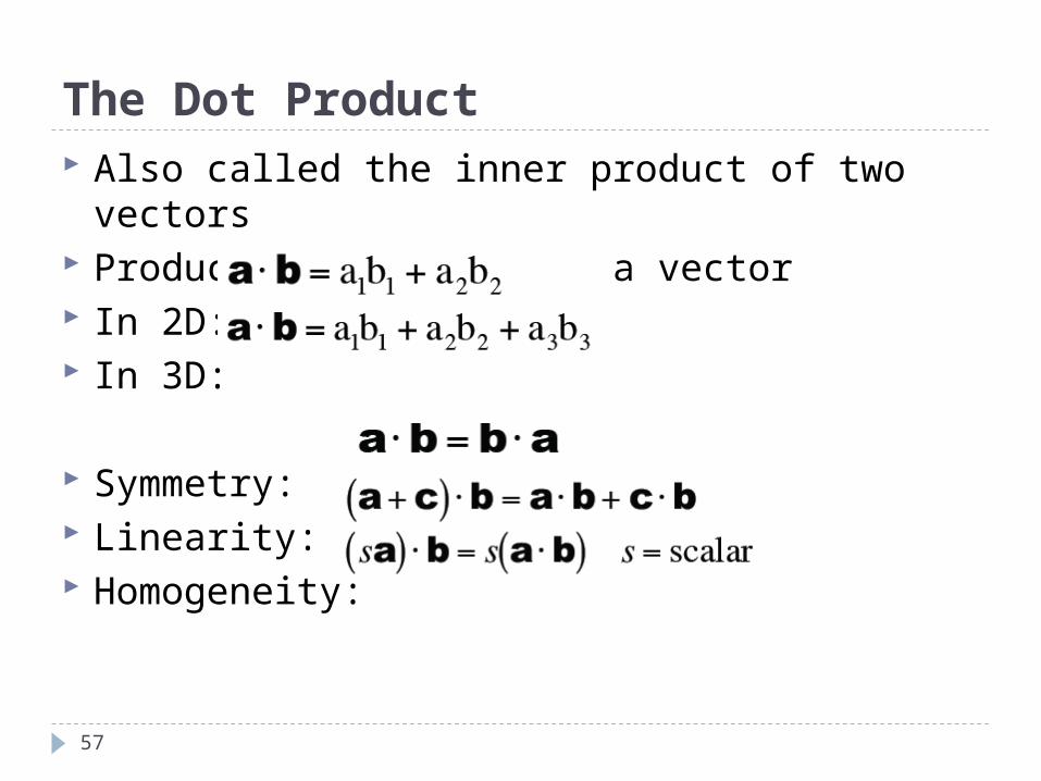
Also called the inner product of two vectors Produces a number, not a vector In 2D: In 3D:
Symmetry: Linearity: Homogeneity:
Length of a Vector
58
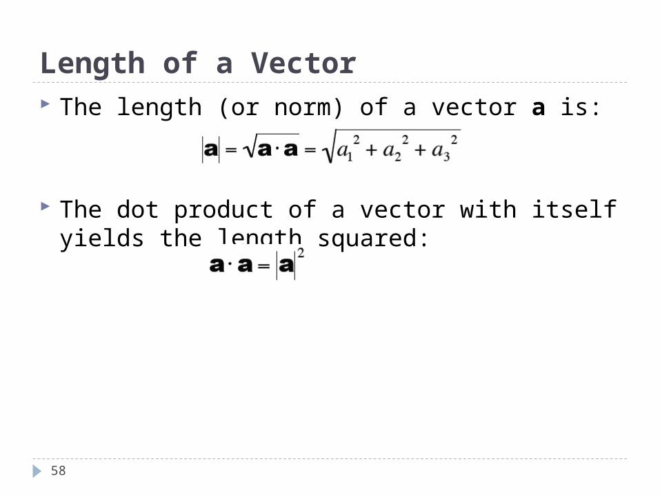
The length (or norm) of a vector a is:
The dot product of a vector with itself yields the length squared:
Unit Vectors and Normalization
59
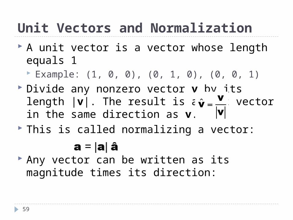
A unit vector is a vector whose length equals 1 Example: (1, 0, 0), (0, 1, 0), (0, 0, 1)
Divide any nonzero vector v by its length |v|. The result is a unit vector in the same direction as v.
This is called normalizing a vector:
Any vector can be written as its magnitude times its direction:
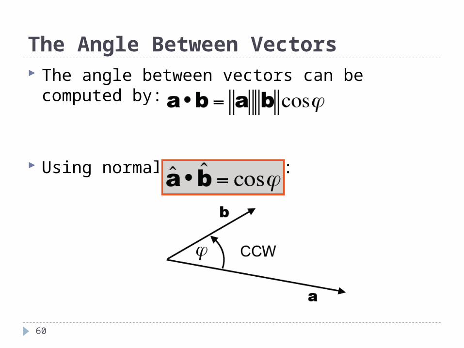
The Angle Between Vectors
60
The angle between vectors can be computed by:
Using normalized vectors:
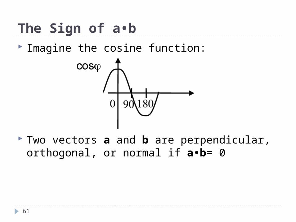
The Sign of a•b
61
Imagine the cosine function:
Two vectors a and b are perpendicular, orthogonal, or normal if a•b= 0
The end
62
Questions and answers