Embed Size (px)
Citation preview
1 © 2015 ANSYS, Inc. November 12, 2015 ANSYS Confidential
Modeling Internal Flow Induced Motion with ANSYS Multiphysics
Chris Wolfe, Michael Tooley
July 2015
2 © 2015 ANSYS, Inc. November 12, 2015 ANSYS Confidential
• Flow Induced Motion
• Overview of Fluid-Structure Interaction Methods
• Examples
• Summary of ANSYS Multiphysics
Agenda
3 © 2015 ANSYS, Inc. November 12, 2015 ANSYS Confidential
• Flow Induced Motion
• Overview of Fluid-Structure Interaction Methods
• Examples
• Summary of ANSYS Multiphysics
Agenda
4 © 2015 ANSYS, Inc. November 12, 2015 ANSYS Confidential
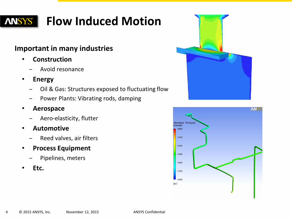
Important in many industries
• Construction
– Avoid resonance
• Energy
– Oil & Gas: Structures exposed to fluctuating flow
– Power Plants: Vibrating rods, damping
• Aerospace
– Aero-elasticity, flutter
• Automotive
– Reed valves, air filters
• Process Equipment
– Pipelines, meters
• Etc.
Flow Induced Motion
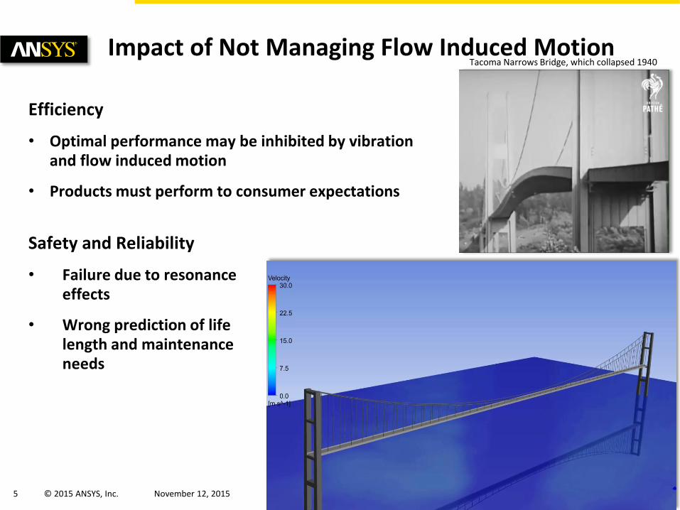
2-way FSI simulation of Tacoma Narrows Bridge
5 © 2015 ANSYS, Inc. November 12, 2015 ANSYS Confidential
Safety and Reliability
• Failure due to resonance effects
• Wrong prediction of life length and maintenance needs
Impact of Not Managing Flow Induced Motion
Efficiency
• Optimal performance may be inhibited by vibration and flow induced motion
• Products must perform to consumer expectations
Tacoma Narrows Bridge, which collapsed 1940
6 © 2015 ANSYS, Inc. November 12, 2015 ANSYS Confidential
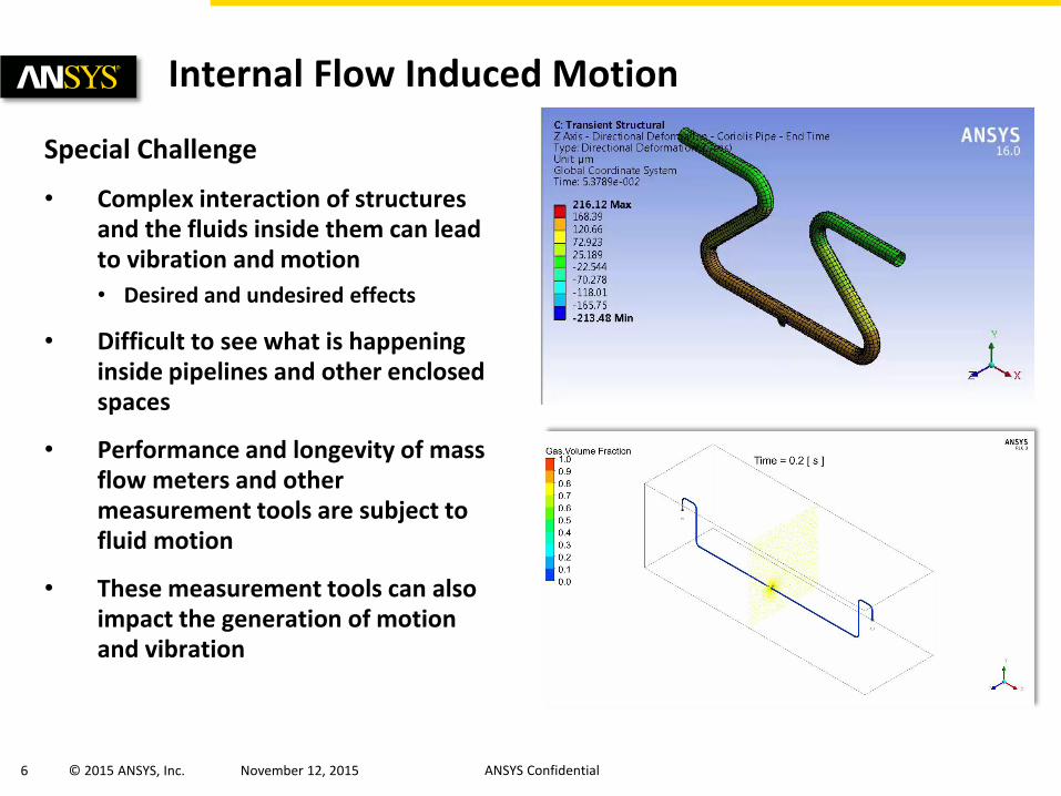
Special Challenge
• Complex interaction of structures and the fluids inside them can lead to vibration and motion
• Desired and undesired effects
• Difficult to see what is happening inside pipelines and other enclosed spaces
• Performance and longevity of mass flow meters and other measurement tools are subject to fluid motion
• These measurement tools can also impact the generation of motion and vibration
Internal Flow Induced Motion

7 © 2015 ANSYS, Inc. November 12, 2015 ANSYS Confidential
• Flow Induced Motion
• Overview of Fluid-Structure Interaction Methods
• Examples
• Validations
• Summary of ANSYS FSI Offering
Agenda
8 © 2015 ANSYS, Inc. November 12, 2015 ANSYS Confidential
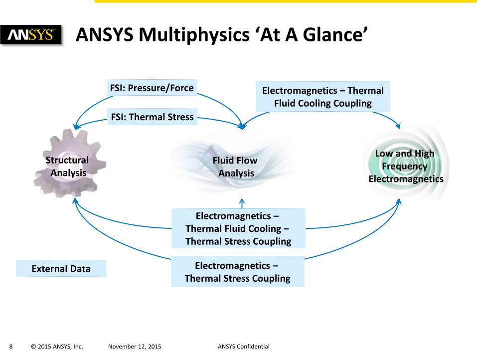
ANSYS Multiphysics ‘At A Glance’
FSI: Thermal Stress
FSI: Pressure/Force Electromagnetics – Thermal Fluid Cooling Coupling
Electromagnetics – Thermal Fluid Cooling – Thermal Stress Coupling
Electromagnetics – Thermal Stress Coupling
External Data
Structural Analysis
Fluid Flow Analysis
Low and High Frequency
Electromagnetics
9 © 2015 ANSYS, Inc. November 12, 2015 ANSYS Confidential
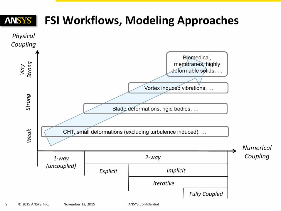
FSI Workflows, Modeling Approaches Physical Coupling
Numerical Coupling
Stro
ng
W
eak
Ver
y St
ron
g
1-way (uncoupled)
2-way
Explicit Implicit
Iterative
Fully Coupled
CHT, small deformations (excluding turbulence induced), …
Vortex induced vibrations, …
Biomedical,
membranes, highly
deformable solids, …
Blade deformations, rigid bodies, …
10 © 2015 ANSYS, Inc. November 12, 2015 ANSYS Confidential
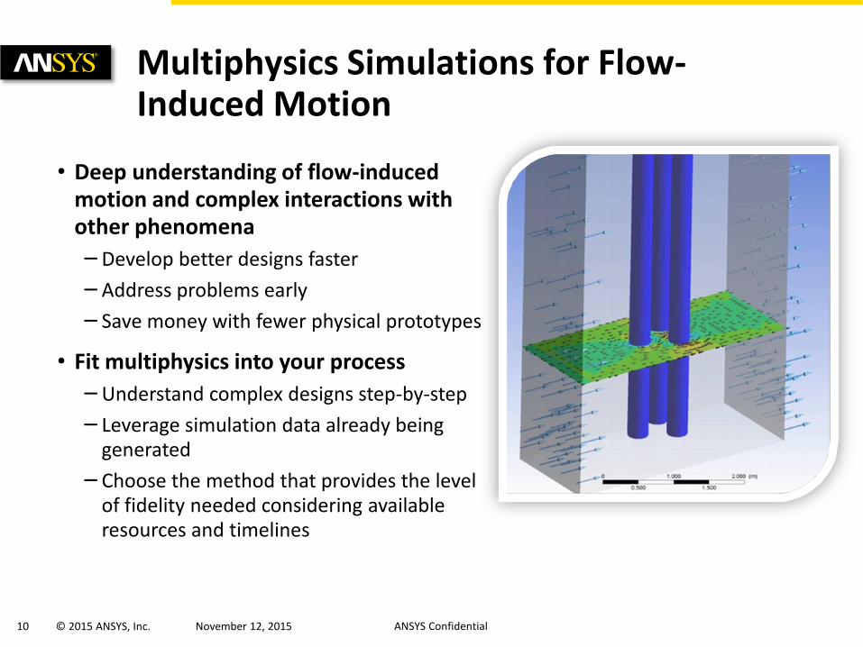
• Deep understanding of flow-induced motion and complex interactions with other phenomena
– Develop better designs faster
– Address problems early
– Save money with fewer physical prototypes
• Fit multiphysics into your process
– Understand complex designs step-by-step
– Leverage simulation data already being generated
– Choose the method that provides the level of fidelity needed considering available resources and timelines
Multiphysics Simulations for Flow-Induced Motion
11 © 2015 ANSYS, Inc. November 12, 2015 ANSYS Confidential
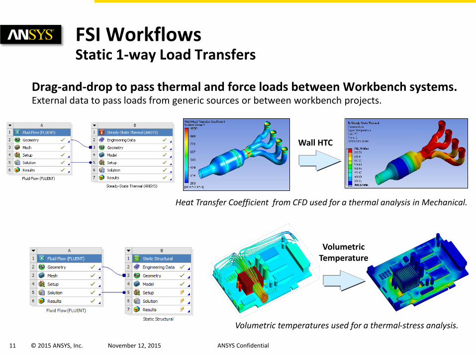
Drag-and-drop to pass thermal and force loads between Workbench systems. External data to pass loads from generic sources or between workbench projects.
FSI Workflows Static 1-way Load Transfers
Volumetric Temperature
Volumetric temperatures used for a thermal-stress analysis.
Wall HTC
Heat Transfer Coefficient from CFD used for a thermal analysis in Mechanical.
12 © 2015 ANSYS, Inc. November 12, 2015 ANSYS Confidential
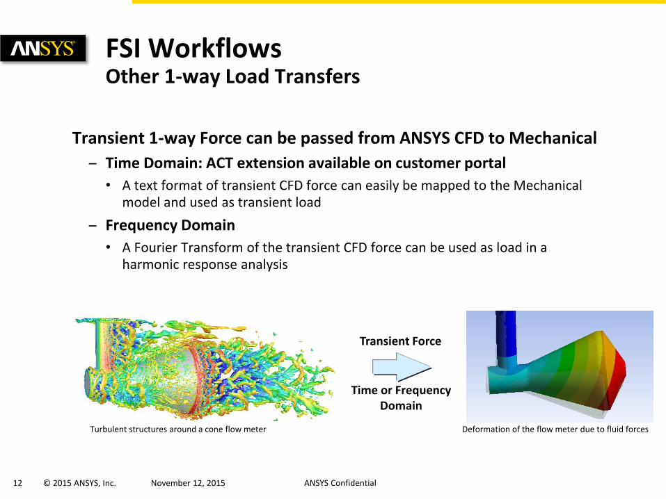
Transient 1-way Force can be passed from ANSYS CFD to Mechanical
– Time Domain: ACT extension available on customer portal
• A text format of transient CFD force can easily be mapped to the Mechanical model and used as transient load
– Frequency Domain
• A Fourier Transform of the transient CFD force can be used as load in a harmonic response analysis
Time or Frequency Domain
FSI Workflows Other 1-way Load Transfers
Transient Force
Turbulent structures around a cone flow meter Deformation of the flow meter due to fluid forces
13 © 2015 ANSYS, Inc. November 12, 2015 ANSYS Confidential
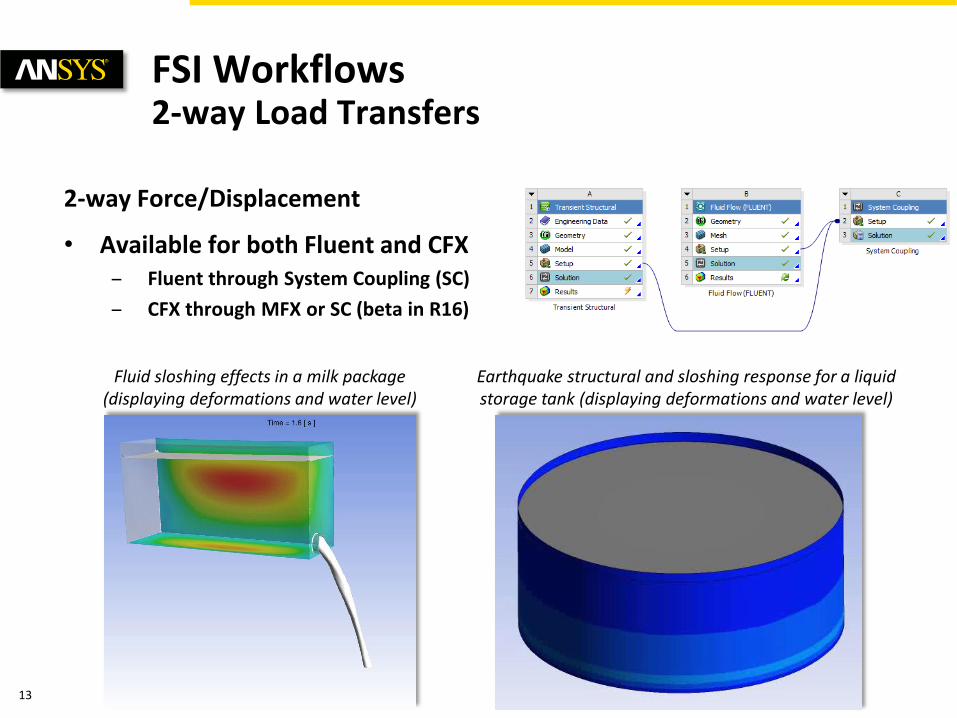
2-way Force/Displacement
• Available for both Fluent and CFX – Fluent through System Coupling (SC)
– CFX through MFX or SC (beta in R16)
FSI Workflows 2-way Load Transfers
Earthquake structural and sloshing response for a liquid storage tank (displaying deformations and water level)
Fluid sloshing effects in a milk package (displaying deformations and water level)
14 © 2015 ANSYS, Inc. November 12, 2015 ANSYS Confidential
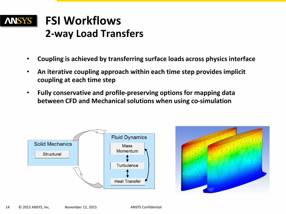
FSI Workflows 2-way Load Transfers
• Coupling is achieved by transferring surface loads across physics interface
• An iterative coupling approach within each time step provides implicit coupling at each time step
• Fully conservative and profile-preserving options for mapping data between CFD and Mechanical solutions when using co-simulation
15 © 2015 ANSYS, Inc. November 12, 2015 ANSYS Confidential
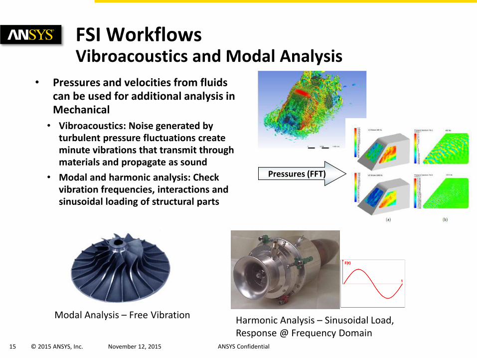
FSI Workflows Vibroacoustics and Modal Analysis
• Pressures and velocities from fluids can be used for additional analysis in Mechanical
• Vibroacoustics: Noise generated by turbulent pressure fluctuations create minute vibrations that transmit through materials and propagate as sound
• Modal and harmonic analysis: Check vibration frequencies, interactions and sinusoidal loading of structural parts
Pressures (FFT)
Modal Analysis – Free Vibration Harmonic Analysis – Sinusoidal Load, Response @ Frequency Domain
16 © 2015 ANSYS, Inc. November 12, 2015 ANSYS Confidential
• Flow Induced Motion
• Overview of Fluid-Structure Interaction Methods
• Examples
• Summary of ANSYS Multiphysics
Agenda

17 © 2015 ANSYS, Inc. November 12, 2015 ANSYS Confidential
• Voith Hydro Water Turbine
• Engine Hydro-mount
• In Depth: Jumper Pipe
• Demo: Coriolis Mass Flow Rate Meter
Examples
18 © 2015 ANSYS, Inc. November 12, 2015 ANSYS Confidential
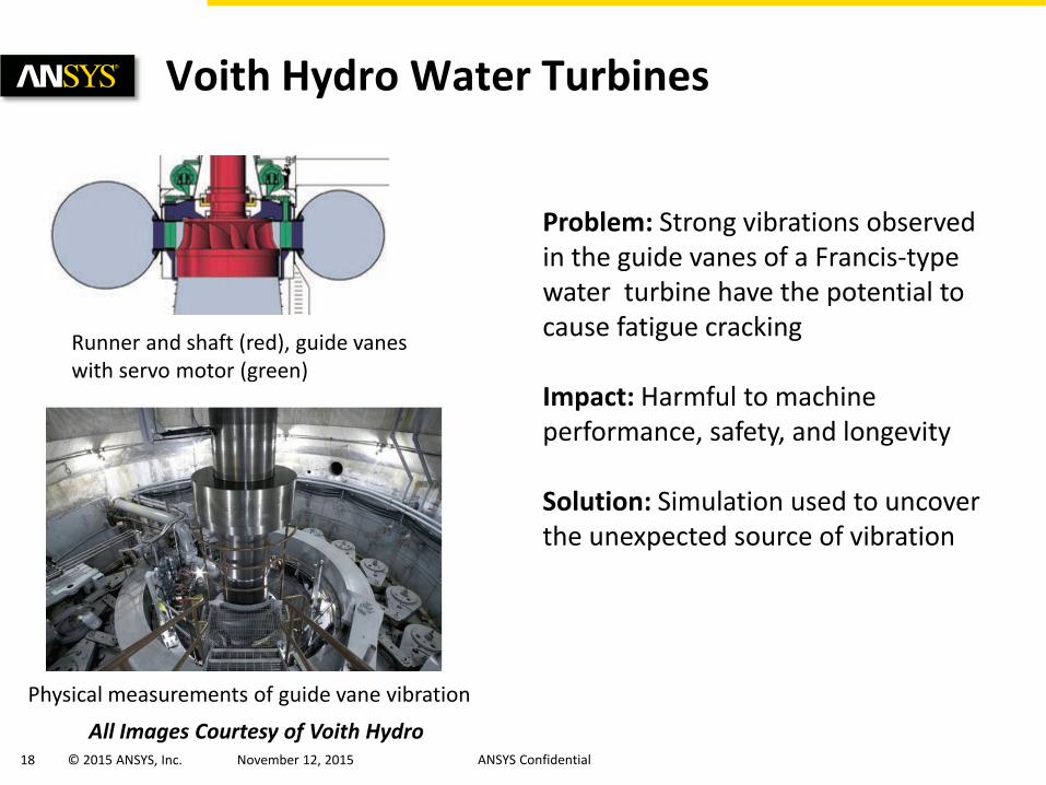
Voith Hydro Water Turbines
Runner and shaft (red), guide vanes with servo motor (green)
Problem: Strong vibrations observed in the guide vanes of a Francis-type water turbine have the potential to cause fatigue cracking Impact: Harmful to machine performance, safety, and longevity Solution: Simulation used to uncover the unexpected source of vibration
Physical measurements of guide vane vibration All Images Courtesy of Voith Hydro
19 © 2015 ANSYS, Inc. November 12, 2015 ANSYS Confidential
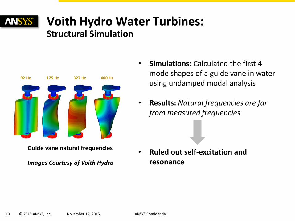
Voith Hydro Water Turbines: Structural Simulation
Guide vane natural frequencies
92 Hz 175 Hz 327 Hz 400 Hz
Images Courtesy of Voith Hydro
• Simulations: Calculated the first 4 mode shapes of a guide vane in water using undamped modal analysis
• Results: Natural frequencies are far
from measured frequencies • Ruled out self-excitation and
resonance
20 © 2015 ANSYS, Inc. November 12, 2015 ANSYS Confidential
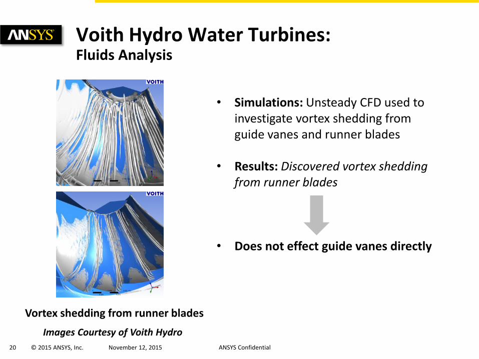
• Simulations: Unsteady CFD used to investigate vortex shedding from guide vanes and runner blades
• Results: Discovered vortex shedding from runner blades
• Does not effect guide vanes directly
Voith Hydro Water Turbines: Fluids Analysis
Images Courtesy of Voith Hydro
Vortex shedding from runner blades
21 © 2015 ANSYS, Inc. November 12, 2015 ANSYS Confidential
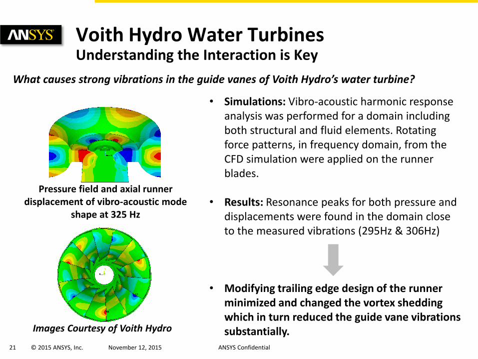
Voith Hydro Water Turbines Understanding the Interaction is Key
What causes strong vibrations in the guide vanes of Voith Hydro’s water turbine?
Images Courtesy of Voith Hydro
• Simulations: Vibro-acoustic harmonic response analysis was performed for a domain including both structural and fluid elements. Rotating force patterns, in frequency domain, from the CFD simulation were applied on the runner blades.
• Results: Resonance peaks for both pressure and displacements were found in the domain close to the measured vibrations (295Hz & 306Hz)
• Modifying trailing edge design of the runner minimized and changed the vortex shedding which in turn reduced the guide vane vibrations substantially.
Pressure field and axial runner displacement of vibro-acoustic mode
shape at 325 Hz
22 © 2015 ANSYS, Inc. November 12, 2015 ANSYS Confidential
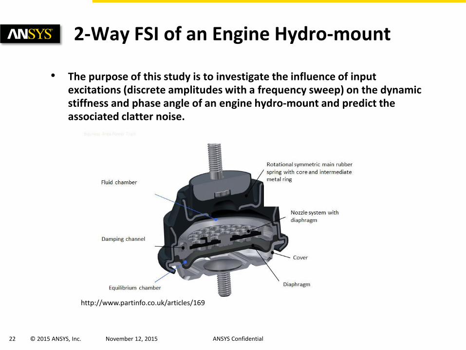
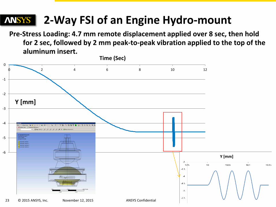
• The purpose of this study is to investigate the influence of input excitations (discrete amplitudes with a frequency sweep) on the dynamic stiffness and phase angle of an engine hydro-mount and predict the associated clatter noise.
2-Way FSI of an Engine Hydro-mount
http://www.partinfo.co.uk/articles/169
23 © 2015 ANSYS, Inc. November 12, 2015 ANSYS Confidential
-6
-5
-4
-3
-2
-1
0
0 2 4 6 8 10 12
Y [mm]
Time (Sec)
Pre-Stress Loading: 4.7 mm remote displacement applied over 8 sec, then hold for 2 sec, followed by 2 mm peak-to-peak vibration applied to the top of the aluminum insert.
2-Way FSI of an Engine Hydro-mount
24 © 2015 ANSYS, Inc. November 12, 2015 ANSYS Confidential
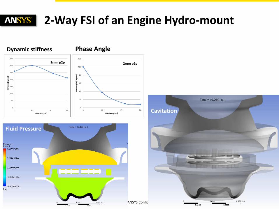
2-Way FSI of an Engine Hydro-mount
Fluid Pressure
Cavitation
Dynamic stiffness Phase Angle

25 © 2015 ANSYS, Inc. November 12, 2015 ANSYS Confidential
• Voith Hydro Water Turbine
• Engine Hydro-mount
• In Depth: Jumper Pipe
• Demo: Coriolis Mass Flow Rate Meter
Examples
26 © 2015 ANSYS, Inc. November 12, 2015 ANSYS Confidential
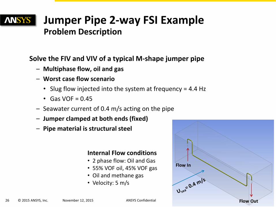
Jumper Pipe 2-way FSI Example Problem Description
Solve the FIV and VIV of a typical M-shape jumper pipe
– Multiphase flow, oil and gas
– Worst case flow scenario
• Slug flow injected into the system at frequency = 4.4 Hz
• Gas VOF = 0.45
– Seawater current of 0.4 m/s acting on the pipe
– Jumper clamped at both ends (fixed)
– Pipe material is structural steel
Internal Flow conditions • 2 phase flow: Oil and Gas • 55% VOF oil, 45% VOF gas • Oil and methane gas
• Velocity: 5 m/s
27 © 2015 ANSYS, Inc. November 12, 2015 ANSYS Confidential
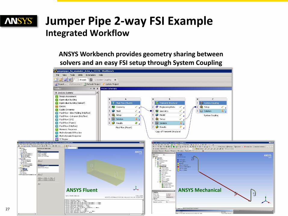
ANSYS Fluent ANSYS Mechanical
Jumper Pipe 2-way FSI Example Integrated Workflow
ANSYS Workbench provides geometry sharing between solvers and an easy FSI setup through System Coupling
28 © 2015 ANSYS, Inc. November 12, 2015 ANSYS Confidential
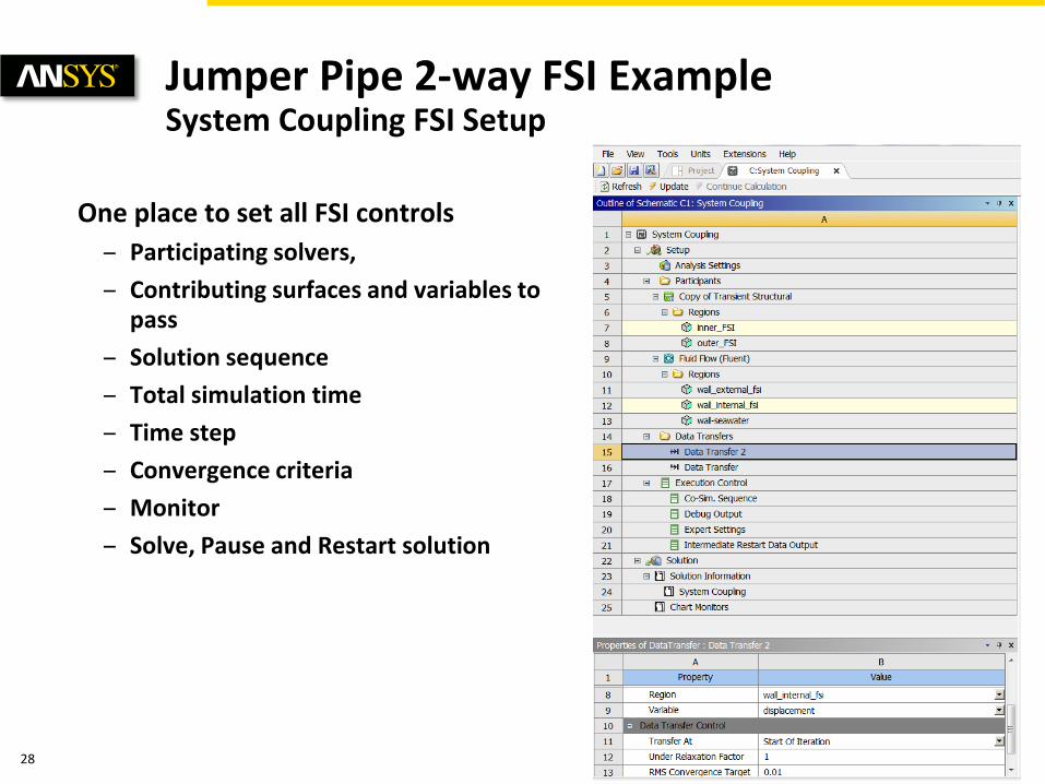
One place to set all FSI controls
– Participating solvers,
– Contributing surfaces and variables to pass
– Solution sequence
– Total simulation time
– Time step
– Convergence criteria
– Monitor
– Solve, Pause and Restart solution
Jumper Pipe 2-way FSI Example System Coupling FSI Setup
29 © 2015 ANSYS, Inc. November 12, 2015 ANSYS Confidential
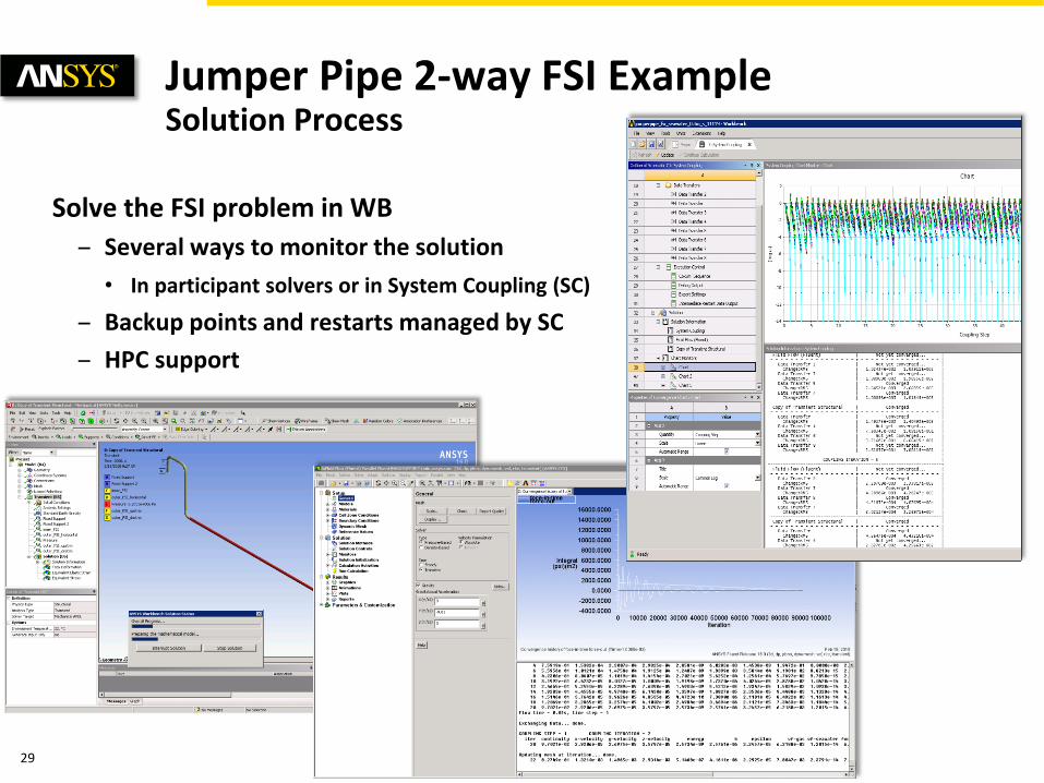
Solve the FSI problem in WB
– Several ways to monitor the solution
• In participant solvers or in System Coupling (SC)
– Backup points and restarts managed by SC
– HPC support
Jumper Pipe 2-way FSI Example Solution Process
30 © 2015 ANSYS, Inc. November 12, 2015 ANSYS Confidential
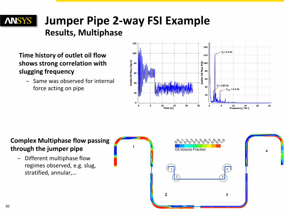
Time history of outlet oil flow shows strong correlation with slugging frequency
– Same was observed for internal force acting on pipe
1
2 3
4
Complex Multiphase flow passing through the jumper pipe
– Different multiphase flow regimes observed, e.g. slug, stratified, annular,…
Jumper Pipe 2-way FSI Example Results, Multiphase
31 © 2015 ANSYS, Inc. November 12, 2015 ANSYS Confidential
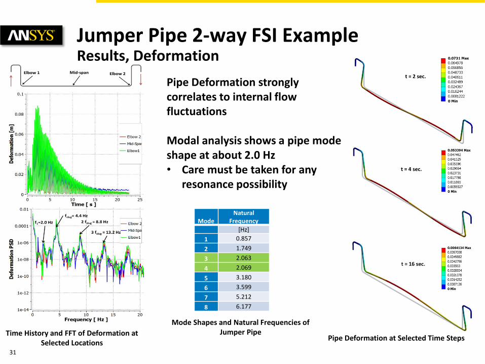
Pipe Deformation at Selected Time Steps Time History and FFT of Deformation at
Selected Locations
Mode
Natural Frequency
[Hz]
1 0.857
2 1.749
3 2.063
4 2.069
5 3.180
6 3.599
7 5.212
8 6.177
Mode Shapes and Natural Frequencies of Jumper Pipe
Pipe Deformation strongly correlates to internal flow fluctuations Modal analysis shows a pipe mode shape at about 2.0 Hz • Care must be taken for any
resonance possibility
Jumper Pipe 2-way FSI Example Results, Deformation
32 © 2015 ANSYS, Inc. November 12, 2015 ANSYS Confidential
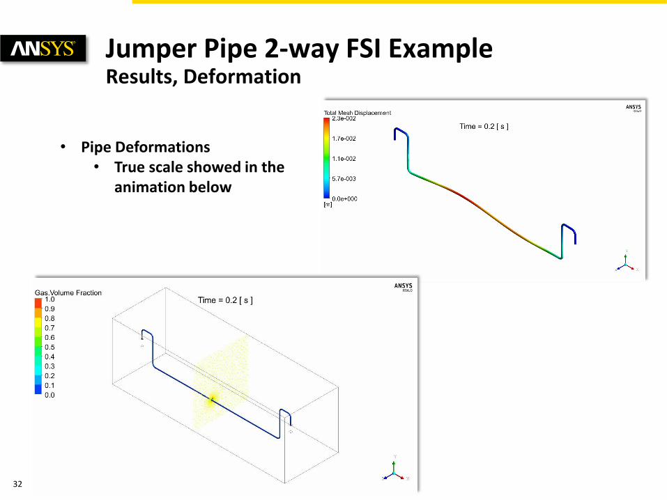
Jumper Pipe 2-way FSI Example Results, Deformation
• Pipe Deformations • True scale showed in the
animation below
33 © 2015 ANSYS, Inc. November 12, 2015 ANSYS Confidential
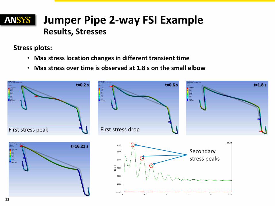
Stress plots:
• Max stress location changes in different transient time
• Max stress over time is observed at 1.8 s on the small elbow
t=0.2 s t=0.6 s t=1.8 s
t=16.21 s
First stress peak First stress drop
Secondary stress peaks
Jumper Pipe 2-way FSI Example Results, Stresses
34 © 2015 ANSYS, Inc. November 12, 2015 ANSYS Confidential
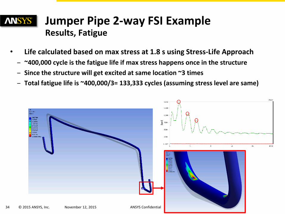
• Life calculated based on max stress at 1.8 s using Stress-Life Approach
– ~400,000 cycle is the fatigue life if max stress happens once in the structure
– Since the structure will get excited at same location ~3 times
– Total fatigue life is ~400,000/3= 133,333 cycles (assuming stress level are same)
Jumper Pipe 2-way FSI Example Results, Fatigue
35 © 2015 ANSYS, Inc. November 12, 2015 ANSYS Confidential
2-way FSI analysis performed for a typical subsea M-shape jumper pipe carrying multiphase flow
Worst case scenario of internal slugging flow considered
Results showed
– Maximum deformation of 0.08 m
– Pipe deformation correlates strongly with the flow slugging frequency
– Modal analysis is important to investigate any resonance possibility
– Fatigue risk after 133,000 load cycles
Jumper Pipe 2-way FSI Example Summary
36 © 2015 ANSYS, Inc. November 12, 2015 ANSYS Confidential
• Voith Hydro Water Turbine
• Engine Hydro-mount
• In Depth: Jumper Pipe
• Demo: Coriolis Mass Flow Rate Meter
Examples

37 © 2015 ANSYS, Inc. November 12, 2015 ANSYS Confidential
Multiphysics Bundles
Multiphysics Bundle Included Solvers
ANSYS Mechanical CFD ANSYS CFD, Mechanical
ANSYS Mechanical Emag Maxwell ANSYS Mechanical Emag , Maxwell 3D
ANSYS Mechanical CFD Maxwell ANSYS Mechanical Emag, CFD, Maxwell 3D
• ANSYS CFD includes ANSYS Fluent and ANSYS CFX
• Share ANSYS HPC keys between ANSYS CFD and ANSYS Mechanical
• As of R16, the multiphysics bundles also include: SpaceClaim, Design Explorer, and AIM
38 © 2015 ANSYS, Inc. November 12, 2015 ANSYS Confidential
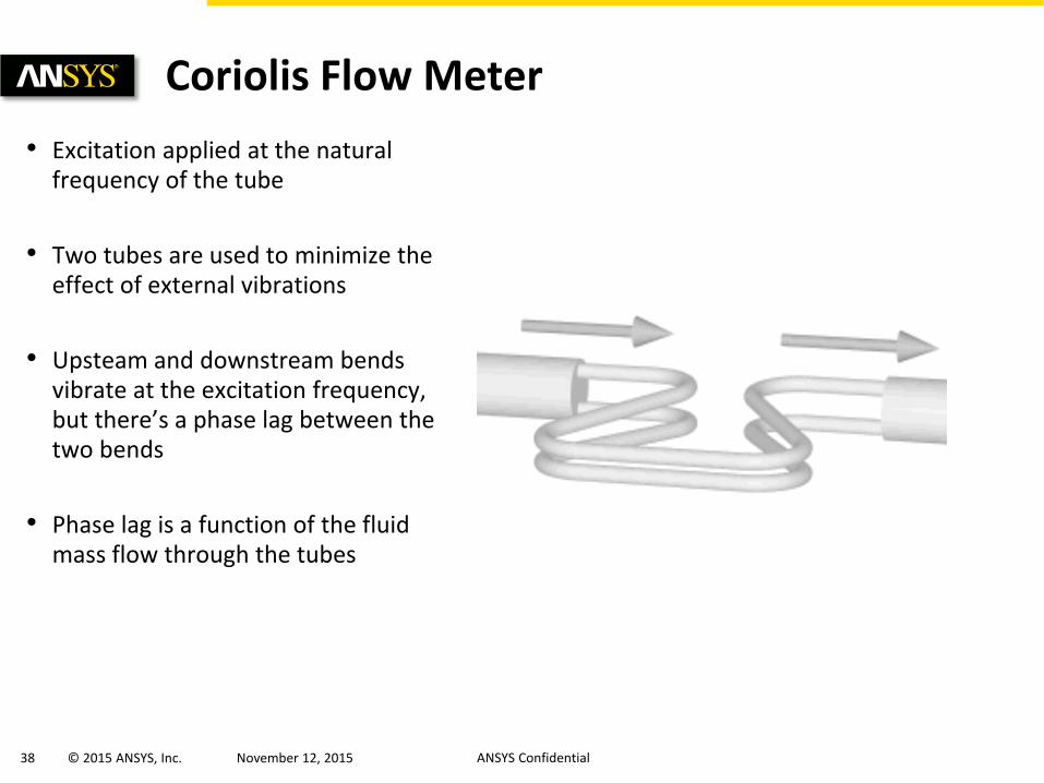
Coriolis Flow Meter
• Excitation applied at the natural frequency of the tube
• Two tubes are used to minimize the effect of external vibrations
• Upsteam and downstream bends vibrate at the excitation frequency, but there’s a phase lag between the two bends
• Phase lag is a function of the fluid mass flow through the tubes
39 © 2015 ANSYS, Inc. November 12, 2015 ANSYS Confidential
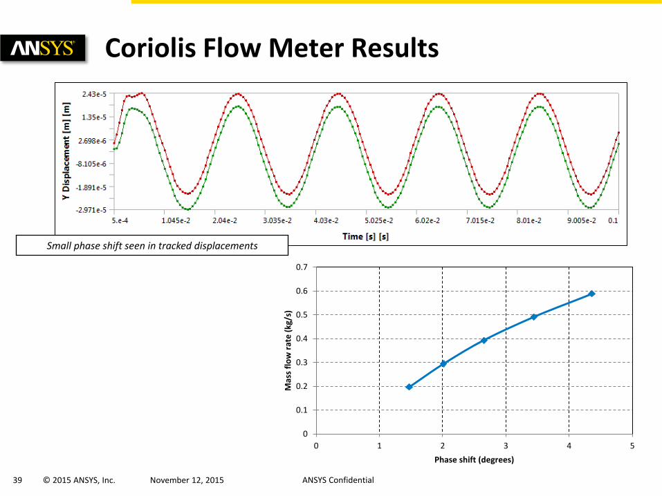
Coriolis Flow Meter Results
Small phase shift seen in tracked displacements
0
0.1
0.2
0.3
0.4
0.5
0.6
0.7
0 1 2 3 4 5
Mas
s fl
ow
rat
e (
kg/s
)
Phase shift (degrees)
40 © 2015 ANSYS, Inc. November 12, 2015 ANSYS Confidential
• Flow Induced Motion
• Overview of Fluid-Structure Interaction Methods
• Examples
• Summary of ANSYS Multiphysics
Agenda
41 © 2015 ANSYS, Inc. November 12, 2015 ANSYS Confidential
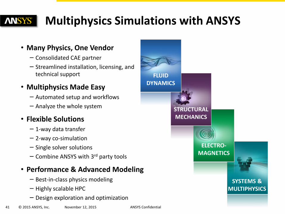
SYSTEMS & MULTIPHYSICS
ELECTRO- MAGNETICS
STRUCTURAL MECHANICS
FLUID DYNAMICS
• Many Physics, One Vendor – Consolidated CAE partner
– Streamlined installation, licensing, and technical support
• Multiphysics Made Easy – Automated setup and workflows
– Analyze the whole system
• Flexible Solutions – 1-way data transfer
– 2-way co-simulation
– Single solver solutions
– Combine ANSYS with 3rd party tools
• Performance & Advanced Modeling – Best-in-class physics modeling
– Highly scalable HPC
– Design exploration and optimization
Multiphysics Simulations with ANSYS
42 © 2015 ANSYS, Inc. November 12, 2015 ANSYS Confidential
Thank you!