Embed Size (px)
Citation preview

0435
0576
6.81
ModiconLadder Logic Block Library User GuideVolume 1840 USE 101 00
4/2006
This document provided by Barr-Thorp Electric Co., Inc. 800-473-9123 www.barr-thorp.com

ii
This document provided by Barr-Thorp Electric Co., Inc. 800-473-9123 www.barr-thorp.com
iii
Table of Contents
Safety Information . . . . . . . . . . . . . . . . . . . . . . . . . . . . . . . . .xxvii
About the Book . . . . . . . . . . . . . . . . . . . . . . . . . . . . . . . . . . . . xxix
Part I General Information . . . . . . . . . . . . . . . . . . . . . . . . . . . . . . 1
Chapter 1 Ladder Logic Overview . . . . . . . . . . . . . . . . . . . . . . . . . . . . . . . .3Segments and Networks in Ladder Logic . . . . . . . . . . . . . . . . . . . . . . . . . . . . . . . 4How a PLC Solves Ladder Logic. . . . . . . . . . . . . . . . . . . . . . . . . . . . . . . . . . . . . . 7Ladder Logic Elements and Instructions . . . . . . . . . . . . . . . . . . . . . . . . . . . . . . . . 8
Chapter 2 Memory Allocation in a PLC . . . . . . . . . . . . . . . . . . . . . . . . . . .15User Memory. . . . . . . . . . . . . . . . . . . . . . . . . . . . . . . . . . . . . . . . . . . . . . . . . . . . 16State RAM Values. . . . . . . . . . . . . . . . . . . . . . . . . . . . . . . . . . . . . . . . . . . . . . . . 18State RAM Structure . . . . . . . . . . . . . . . . . . . . . . . . . . . . . . . . . . . . . . . . . . . . . . 20The Configuration Table . . . . . . . . . . . . . . . . . . . . . . . . . . . . . . . . . . . . . . . . . . . 22The I/O Map Table . . . . . . . . . . . . . . . . . . . . . . . . . . . . . . . . . . . . . . . . . . . . . . . 26
Chapter 3 Ladder Logic Opcodes. . . . . . . . . . . . . . . . . . . . . . . . . . . . . . . .27Translating Ladder Logic Elements in the System Memory Database . . . . . . . . 28Translating DX Instructions in the System Memory Database . . . . . . . . . . . . . . 30Opcode Defaults for Loadables. . . . . . . . . . . . . . . . . . . . . . . . . . . . . . . . . . . . . . 33
Chapter 4 Instructions . . . . . . . . . . . . . . . . . . . . . . . . . . . . . . . . . . . . . . . . .35Parameter Assignment of Instuctions . . . . . . . . . . . . . . . . . . . . . . . . . . . . . . . . . 35
This document provided by Barr-Thorp Electric Co., Inc. 800-473-9123 www.barr-thorp.com
iv
Chapter 5 Instruction Groups. . . . . . . . . . . . . . . . . . . . . . . . . . . . . . . . . . . 37Instruction Groups . . . . . . . . . . . . . . . . . . . . . . . . . . . . . . . . . . . . . . . . . . . . . . . . 38ASCII Functions . . . . . . . . . . . . . . . . . . . . . . . . . . . . . . . . . . . . . . . . . . . . . . . . . . 39Counters and Timers Instructions . . . . . . . . . . . . . . . . . . . . . . . . . . . . . . . . . . . . 40Fast I/O Instructions. . . . . . . . . . . . . . . . . . . . . . . . . . . . . . . . . . . . . . . . . . . . . . . 41Loadable DX . . . . . . . . . . . . . . . . . . . . . . . . . . . . . . . . . . . . . . . . . . . . . . . . . . . . 42Math Instructions . . . . . . . . . . . . . . . . . . . . . . . . . . . . . . . . . . . . . . . . . . . . . . . . . 43Matrix Instructions . . . . . . . . . . . . . . . . . . . . . . . . . . . . . . . . . . . . . . . . . . . . . . . . 45Miscellaneous . . . . . . . . . . . . . . . . . . . . . . . . . . . . . . . . . . . . . . . . . . . . . . . . . . . 46Move Instructions. . . . . . . . . . . . . . . . . . . . . . . . . . . . . . . . . . . . . . . . . . . . . . . . . 47Skips/Specials . . . . . . . . . . . . . . . . . . . . . . . . . . . . . . . . . . . . . . . . . . . . . . . . . . . 48Special Instructions . . . . . . . . . . . . . . . . . . . . . . . . . . . . . . . . . . . . . . . . . . . . . . . 49Coils, Contacts and Interconnects . . . . . . . . . . . . . . . . . . . . . . . . . . . . . . . . . . . . 50
Chapter 6 Equation Networks . . . . . . . . . . . . . . . . . . . . . . . . . . . . . . . . . . 51Equation Network Structure . . . . . . . . . . . . . . . . . . . . . . . . . . . . . . . . . . . . . . . . . 52Mathematical Equations in Equation Networks . . . . . . . . . . . . . . . . . . . . . . . . . . 55Mathematical Operations in Equation Networks . . . . . . . . . . . . . . . . . . . . . . . . . 59Mathematical Functions in Equation Networks . . . . . . . . . . . . . . . . . . . . . . . . . . 64Data Conversions in an Equation Network . . . . . . . . . . . . . . . . . . . . . . . . . . . . . 66Roundoff Differences in PLCs without a Math Coprocessor . . . . . . . . . . . . . . . . 68Benchmark Performance . . . . . . . . . . . . . . . . . . . . . . . . . . . . . . . . . . . . . . . . . . . 69
Chapter 7 Closed Loop Control / Analog Values . . . . . . . . . . . . . . . . . . . 71Closed Loop Control / Analog Values . . . . . . . . . . . . . . . . . . . . . . . . . . . . . . . . . 72PCFL Subfunctions . . . . . . . . . . . . . . . . . . . . . . . . . . . . . . . . . . . . . . . . . . . . . . . 73A PID Example. . . . . . . . . . . . . . . . . . . . . . . . . . . . . . . . . . . . . . . . . . . . . . . . . . . 77PID2 Level Control Example . . . . . . . . . . . . . . . . . . . . . . . . . . . . . . . . . . . . . . . . 80
Chapter 8 Formatting Messages for ASCII READ/WRIT Operations . . . 83Formatting Messages for ASCII READ/WRIT Operations . . . . . . . . . . . . . . . . . . 84Format Specifiers. . . . . . . . . . . . . . . . . . . . . . . . . . . . . . . . . . . . . . . . . . . . . . . . . 85Special Set-up Considerations for Control/Monitor Signals Format. . . . . . . . . . . . . . . . . . . . . . . . . . . . . . . . . . . . . . . . . . . . . . . . . . . 88
Chapter 9 Coils, Contacts and Interconnects. . . . . . . . . . . . . . . . . . . . . . 91Coils . . . . . . . . . . . . . . . . . . . . . . . . . . . . . . . . . . . . . . . . . . . . . . . . . . . . . . . . . . . 92Contacts. . . . . . . . . . . . . . . . . . . . . . . . . . . . . . . . . . . . . . . . . . . . . . . . . . . . . . . . 94Interconnects (Shorts) . . . . . . . . . . . . . . . . . . . . . . . . . . . . . . . . . . . . . . . . . . . . . 96
Chapter 10 Interrupt Handling . . . . . . . . . . . . . . . . . . . . . . . . . . . . . . . . . . . 97
Chapter 11 Subroutine Handling . . . . . . . . . . . . . . . . . . . . . . . . . . . . . . . . . 99
This document provided by Barr-Thorp Electric Co., Inc. 800-473-9123 www.barr-thorp.com
v
Chapter 12 Installation of DX Loadables . . . . . . . . . . . . . . . . . . . . . . . . . .101
Part II Instruction Descriptions (A to D) . . . . . . . . . . . . . . . . . 103
Chapter 13 1X3X - Input Simulation . . . . . . . . . . . . . . . . . . . . . . . . . . . . . .105Short Description: 1X3X - Input Simulation . . . . . . . . . . . . . . . . . . . . . . . . . . . . 106Representation: 1X3X - Input Simulation . . . . . . . . . . . . . . . . . . . . . . . . . . . . . 107
Chapter 14 AD16: Ad 16 Bit. . . . . . . . . . . . . . . . . . . . . . . . . . . . . . . . . . . . .109Short Description. . . . . . . . . . . . . . . . . . . . . . . . . . . . . . . . . . . . . . . . . . . . . . . . 110Representation: AD16 - 16-bit Addition. . . . . . . . . . . . . . . . . . . . . . . . . . . . . . . 111
Chapter 15 ADD: Addition . . . . . . . . . . . . . . . . . . . . . . . . . . . . . . . . . . . . . .113Short Description. . . . . . . . . . . . . . . . . . . . . . . . . . . . . . . . . . . . . . . . . . . . . . . . 114Representation: ADD - Single Precision Add . . . . . . . . . . . . . . . . . . . . . . . . . . 115
Chapter 16 AND: Logical And . . . . . . . . . . . . . . . . . . . . . . . . . . . . . . . . . . .117Short Description. . . . . . . . . . . . . . . . . . . . . . . . . . . . . . . . . . . . . . . . . . . . . . . . 118Representation: AND - Logical And . . . . . . . . . . . . . . . . . . . . . . . . . . . . . . . . . 119Parameter Description. . . . . . . . . . . . . . . . . . . . . . . . . . . . . . . . . . . . . . . . . . . . 121
Chapter 17 BCD: Binary to Binary Code . . . . . . . . . . . . . . . . . . . . . . . . . .123Short Description. . . . . . . . . . . . . . . . . . . . . . . . . . . . . . . . . . . . . . . . . . . . . . . . 124Representation: BCD - Binary Coded Decimal Conversion . . . . . . . . . . . . . . . 125
Chapter 18 BLKM: Block Move . . . . . . . . . . . . . . . . . . . . . . . . . . . . . . . . . .127Short Description. . . . . . . . . . . . . . . . . . . . . . . . . . . . . . . . . . . . . . . . . . . . . . . . 128Representation: BLKM - Block Move . . . . . . . . . . . . . . . . . . . . . . . . . . . . . . . . 129
Chapter 19 BLKT: Block to Table . . . . . . . . . . . . . . . . . . . . . . . . . . . . . . . .131Short Description. . . . . . . . . . . . . . . . . . . . . . . . . . . . . . . . . . . . . . . . . . . . . . . . 132Representation: BLKT - Block-to-Table Move. . . . . . . . . . . . . . . . . . . . . . . . . . 133Parameter Description. . . . . . . . . . . . . . . . . . . . . . . . . . . . . . . . . . . . . . . . . . . . 134
Chapter 20 BMDI: Block Move with Interrupts Disabled . . . . . . . . . . . . .135Short Description: BMDI - Block Move Interrupts Disabled. . . . . . . . . . . . . . . . 136Representation: BMDI - Block Move Interrupts Disabled . . . . . . . . . . . . . . . . . 137
Chapter 21 BROT: Bit Rotate . . . . . . . . . . . . . . . . . . . . . . . . . . . . . . . . . . .139Short Description. . . . . . . . . . . . . . . . . . . . . . . . . . . . . . . . . . . . . . . . . . . . . . . . 140Representation: BROT - Bit Rotate . . . . . . . . . . . . . . . . . . . . . . . . . . . . . . . . . . 141Parameter Description. . . . . . . . . . . . . . . . . . . . . . . . . . . . . . . . . . . . . . . . . . . . 142
This document provided by Barr-Thorp Electric Co., Inc. 800-473-9123 www.barr-thorp.com
vi
Chapter 22 CALL: Activate Immediate or Deferred DX Function . . . . . . 143Short Description: CALL - Activate Immediate or Deferred DX Function. . . . . . 144Representation: CALL - Activate Immediate DX Function . . . . . . . . . . . . . . . . . 145Representation: CALL - Activate Deferred DX Function . . . . . . . . . . . . . . . . . . 148
Chapter 23 CANT - Interpret Coils, Contacts, Timers, Counters, and the SUB Block. . . . . . . . . . . . . . . . . . . . . . . . . . . . . . . . . . 151Short Description: CANT - Interpret Coils, Contacts, Timers, Counters, and the SUB Block . . . . . . . . . . . . . . . . . . . . . . . . . . . . . . . . . . . . . . 152Representation: CANT - Interpret Coils, Contacts, Timers, Counters, and the SUB Block . . . . . . . . . . . . . . . . . . . . . . . . . . . . . . . . . . . . . . 153Parameter Description: CANT - Interpret Coils, Contacts, Timers, Counters, and the SUB Block . . . . . . . . . . . . . . . . . . . . . . . . . . . . . . . . . . . . . . 154
Chapter 24 CHS: Configure Hot Standby . . . . . . . . . . . . . . . . . . . . . . . . . 157Short Description . . . . . . . . . . . . . . . . . . . . . . . . . . . . . . . . . . . . . . . . . . . . . . . . 158Representation: CHS - Configure Hot Standby . . . . . . . . . . . . . . . . . . . . . . . . . 159Detailed Description. . . . . . . . . . . . . . . . . . . . . . . . . . . . . . . . . . . . . . . . . . . . . . 160
Chapter 25 CKSM: Check Sum. . . . . . . . . . . . . . . . . . . . . . . . . . . . . . . . . . 163Short Description . . . . . . . . . . . . . . . . . . . . . . . . . . . . . . . . . . . . . . . . . . . . . . . . 164Representation: CKSM - Checksum . . . . . . . . . . . . . . . . . . . . . . . . . . . . . . . . . 165Parameter Description . . . . . . . . . . . . . . . . . . . . . . . . . . . . . . . . . . . . . . . . . . . . 166
Chapter 26 CMPR: Compare Register . . . . . . . . . . . . . . . . . . . . . . . . . . . . 167Short Description . . . . . . . . . . . . . . . . . . . . . . . . . . . . . . . . . . . . . . . . . . . . . . . . 168Representation: CMPR - Logical Compare . . . . . . . . . . . . . . . . . . . . . . . . . . . . 169Parameter Description . . . . . . . . . . . . . . . . . . . . . . . . . . . . . . . . . . . . . . . . . . . . 170
Chapter 27 Coils . . . . . . . . . . . . . . . . . . . . . . . . . . . . . . . . . . . . . . . . . . . . . 171Short Description: Coils . . . . . . . . . . . . . . . . . . . . . . . . . . . . . . . . . . . . . . . . . . . 172General Usage Guidelines: Coils. . . . . . . . . . . . . . . . . . . . . . . . . . . . . . . . . . . . 173
Chapter 28 COMM - ASCII Communications Function . . . . . . . . . . . . . . 175Short Description: COMM - ASCII Communications Block . . . . . . . . . . . . . . . . 176Representation: COMM - ASCII Communications Function . . . . . . . . . . . . . . . 177
Chapter 29 COMP: Complement a Matrix . . . . . . . . . . . . . . . . . . . . . . . . . 179Short Description . . . . . . . . . . . . . . . . . . . . . . . . . . . . . . . . . . . . . . . . . . . . . . . . 180Representation: COMP - Logical Compliment . . . . . . . . . . . . . . . . . . . . . . . . . . 181Parameter Description . . . . . . . . . . . . . . . . . . . . . . . . . . . . . . . . . . . . . . . . . . . . 183
Chapter 30 Contacts . . . . . . . . . . . . . . . . . . . . . . . . . . . . . . . . . . . . . . . . . . 185Short Description: Contacts . . . . . . . . . . . . . . . . . . . . . . . . . . . . . . . . . . . . . . . . 186Representation: Contacts . . . . . . . . . . . . . . . . . . . . . . . . . . . . . . . . . . . . . . . . . 187
This document provided by Barr-Thorp Electric Co., Inc. 800-473-9123 www.barr-thorp.com
vii
Chapter 31 CONV - Convert Data . . . . . . . . . . . . . . . . . . . . . . . . . . . . . . . .189Short Description: CONV - Convert Data . . . . . . . . . . . . . . . . . . . . . . . . . . . . . 190Representation: CONV - Convert Data . . . . . . . . . . . . . . . . . . . . . . . . . . . . . . . 191
Chapter 32 CTIF - Counter, Timer, and Interrupt Function. . . . . . . . . . . .193Short Description: CTIF - Counter, Timer, and Interrupt Function . . . . . . . . . . 194Representation: CTIF - Counter, Timer, Interrupt Function. . . . . . . . . . . . . . . . 195Parameter Description: CTIF - Register Usage Table (Top Node) . . . . . . . . . . 196
Chapter 33 DCTR: Down Counter . . . . . . . . . . . . . . . . . . . . . . . . . . . . . . . .203Short Description. . . . . . . . . . . . . . . . . . . . . . . . . . . . . . . . . . . . . . . . . . . . . . . . 204Representation: DCTR - Down Counter . . . . . . . . . . . . . . . . . . . . . . . . . . . . . . 205
Chapter 34 DIOH: Distributed I/O Health . . . . . . . . . . . . . . . . . . . . . . . . . .207Short Description. . . . . . . . . . . . . . . . . . . . . . . . . . . . . . . . . . . . . . . . . . . . . . . . 208Representation: DIOH - Distributed I/O Health . . . . . . . . . . . . . . . . . . . . . . . . . 209Parameter Description. . . . . . . . . . . . . . . . . . . . . . . . . . . . . . . . . . . . . . . . . . . . 211
Chapter 35 DISA - Disabled Discrete Monitor. . . . . . . . . . . . . . . . . . . . . .213Short Description: DISA - Disabled Discrete Monitor . . . . . . . . . . . . . . . . . . . . 214Representation: DISA - Disabled Discrete Monitor . . . . . . . . . . . . . . . . . . . . . . 215
Chapter 36 DIV: Divide. . . . . . . . . . . . . . . . . . . . . . . . . . . . . . . . . . . . . . . . .217Short Description. . . . . . . . . . . . . . . . . . . . . . . . . . . . . . . . . . . . . . . . . . . . . . . . 218Representation: DIV - Single Precision Division . . . . . . . . . . . . . . . . . . . . . . . . 219Example . . . . . . . . . . . . . . . . . . . . . . . . . . . . . . . . . . . . . . . . . . . . . . . . . . . . . . 221
Chapter 37 DLOG: Data Logging for PCMCIA Read/Write Support. . . . .223Short Description. . . . . . . . . . . . . . . . . . . . . . . . . . . . . . . . . . . . . . . . . . . . . . . . 224Representation: DLOG . . . . . . . . . . . . . . . . . . . . . . . . . . . . . . . . . . . . . . . . . . . 225Parameter Description. . . . . . . . . . . . . . . . . . . . . . . . . . . . . . . . . . . . . . . . . . . . 226Run Time Error Handling. . . . . . . . . . . . . . . . . . . . . . . . . . . . . . . . . . . . . . . . . . 228
Chapter 38 DMTH - Double Precision Math . . . . . . . . . . . . . . . . . . . . . . . .229Short Description: DMTH - Double Precision Math - Addition, Subtraction, Multiplication, and Division. . . . . . . . . . . . . . . . . . . . . . . 230Representation: DMTH - Double Precision Math - Addition, Subtraction, Multiplication, and Division. . . . . . . . . . . . . . . . . . . . . . . 231
Chapter 39 DRUM: DRUM Sequencer. . . . . . . . . . . . . . . . . . . . . . . . . . . . .237Short Description. . . . . . . . . . . . . . . . . . . . . . . . . . . . . . . . . . . . . . . . . . . . . . . . 238Representation: DRUM . . . . . . . . . . . . . . . . . . . . . . . . . . . . . . . . . . . . . . . . . . . 239Parameter Description. . . . . . . . . . . . . . . . . . . . . . . . . . . . . . . . . . . . . . . . . . . . 241
This document provided by Barr-Thorp Electric Co., Inc. 800-473-9123 www.barr-thorp.com
viii
Chapter 40 DV16: Divide 16 Bit . . . . . . . . . . . . . . . . . . . . . . . . . . . . . . . . . 243Short Description . . . . . . . . . . . . . . . . . . . . . . . . . . . . . . . . . . . . . . . . . . . . . . . . 244Representation: DV16 - 16-bit Division . . . . . . . . . . . . . . . . . . . . . . . . . . . . . . . 245Example . . . . . . . . . . . . . . . . . . . . . . . . . . . . . . . . . . . . . . . . . . . . . . . . . . . . . . . 247
Part III Instruction Descriptions (E) . . . . . . . . . . . . . . . . . . . . . .249
Chapter 41 EARS - Event/Alarm Recording System . . . . . . . . . . . . . . . . 251Short Description: EARS - Event/Alarm Recording System . . . . . . . . . . . . . . . 252Representation: EARS - Event/Alarm Recording System . . . . . . . . . . . . . . . . . 253Parameter Description: EARS - Event/Alarm Recording System . . . . . . . . . . . 255
Chapter 42 EMTH: Extended Math . . . . . . . . . . . . . . . . . . . . . . . . . . . . . . . 259Short Description . . . . . . . . . . . . . . . . . . . . . . . . . . . . . . . . . . . . . . . . . . . . . . . . 260Representation: EMTH - Extended Math Functions . . . . . . . . . . . . . . . . . . . . . 261Parameter Description . . . . . . . . . . . . . . . . . . . . . . . . . . . . . . . . . . . . . . . . . . . . 262Floating Point EMTH Functions . . . . . . . . . . . . . . . . . . . . . . . . . . . . . . . . . . . . . 264
Chapter 43 EMTH-ADDDP: Double Precision Addition . . . . . . . . . . . . . . 265Short Description . . . . . . . . . . . . . . . . . . . . . . . . . . . . . . . . . . . . . . . . . . . . . . . . 266Representation: EMTH - ADDDP - Double Precision Math - Addition . . . . . . . . 267Parameter Description . . . . . . . . . . . . . . . . . . . . . . . . . . . . . . . . . . . . . . . . . . . . 269
Chapter 44 EMTH-ADDFP: Floating Point Addition . . . . . . . . . . . . . . . . . 271Short Description . . . . . . . . . . . . . . . . . . . . . . . . . . . . . . . . . . . . . . . . . . . . . . . . 272Representation: EMTH - ADDFP - Floating Point Math - Addition. . . . . . . . . . . 273Parameter Description . . . . . . . . . . . . . . . . . . . . . . . . . . . . . . . . . . . . . . . . . . . . 274
Chapter 45 EMTH-ADDIF: Integer + Floating Point Addition. . . . . . . . . . 275Short Description . . . . . . . . . . . . . . . . . . . . . . . . . . . . . . . . . . . . . . . . . . . . . . . . 276Representation: EMTH - ADDIF - Integer + Floating Point Addition . . . . . . . . . 277Parameter Description . . . . . . . . . . . . . . . . . . . . . . . . . . . . . . . . . . . . . . . . . . . . 278
Chapter 46 EMTH-ANLOG: Base 10 Antilogarithm . . . . . . . . . . . . . . . . . 279Short Description . . . . . . . . . . . . . . . . . . . . . . . . . . . . . . . . . . . . . . . . . . . . . . . . 280Representation: EMTH - ANLOG - integer Base 10 Antilogarithm . . . . . . . . . . 281Parameter Description . . . . . . . . . . . . . . . . . . . . . . . . . . . . . . . . . . . . . . . . . . . . 283
Chapter 47 EMTH-ARCOS: Floating Point Arc Cosine of an Angle (in Radians) . . . . . . . . . . . . . . . . . . . . . . . . . . . . . 285Short Description . . . . . . . . . . . . . . . . . . . . . . . . . . . . . . . . . . . . . . . . . . . . . . . . 286Representation: EMTH - ARCOS - Floating Point Math - Arc Cosine of an Angle (in Radians) . . . . . . . . . . . . . . . . . . . . . . . . . . . . . . . . . 287Parameter Description . . . . . . . . . . . . . . . . . . . . . . . . . . . . . . . . . . . . . . . . . . . . 289
This document provided by Barr-Thorp Electric Co., Inc. 800-473-9123 www.barr-thorp.com

ix
Chapter 48 EMTH-ARSIN: Floating Point Arcsine of an Angle (in Radians) . . . . . . . . . . . . . . . . . . . . . .291Short Description. . . . . . . . . . . . . . . . . . . . . . . . . . . . . . . . . . . . . . . . . . . . . . . . 292Representation: EMTH - ARSIN - Arcsine of an Angle (in Radians). . . . . . . . . . . . . . . . . . . . . . . . . . . . . . . . . . . . 293Parameter Description. . . . . . . . . . . . . . . . . . . . . . . . . . . . . . . . . . . . . . . . . . . . 294
Chapter 49 EMTH-ARTAN: Floating Point Arc Tangent of an Angle (in Radians) . . . . . . . . . . . . . . . . . . . . . .295Short Description. . . . . . . . . . . . . . . . . . . . . . . . . . . . . . . . . . . . . . . . . . . . . . . . 296Representation: Floating Point Math - Arc Tangent of an Angle (in Radians) . . . . . . . . . . . . . . . . . . . . . . . . . . . . . . . . . . . . . . . . . . 297Parameter Description. . . . . . . . . . . . . . . . . . . . . . . . . . . . . . . . . . . . . . . . . . . . 299
Chapter 50 EMTH-CHSIN: Changing the Sign of a Floating Point Number . . . . . . . . . . . . . . . . . . . . . . . . . . . . . . .301Short Description. . . . . . . . . . . . . . . . . . . . . . . . . . . . . . . . . . . . . . . . . . . . . . . . 302Representation: EMTH - CHSIN - Change the Sign of aFloating Point Number. . . . . . . . . . . . . . . . . . . . . . . . . . . . . . . . . . . . . . . . . . . . 303Parameter Description. . . . . . . . . . . . . . . . . . . . . . . . . . . . . . . . . . . . . . . . . . . . 305
Chapter 51 EMTH-CMPFP: Floating Point Comparison . . . . . . . . . . . . . .307Short Description. . . . . . . . . . . . . . . . . . . . . . . . . . . . . . . . . . . . . . . . . . . . . . . . 308Representation: EMTH - CMFPF - Floating Point Math Comparison . . . . . . . . 309Parameter Description. . . . . . . . . . . . . . . . . . . . . . . . . . . . . . . . . . . . . . . . . . . . 311
Chapter 52 EMTH-CMPIF: Integer-Floating Point Comparison . . . . . . . .313Short Description. . . . . . . . . . . . . . . . . . . . . . . . . . . . . . . . . . . . . . . . . . . . . . . . 314Representation: EMTH - CMPIF - Floating Point Math - Integer/Floating Point Comparison . . . . . . . . . . . . . . . . . . . . . . . . . . . . . . . . . . 315Parameter Description. . . . . . . . . . . . . . . . . . . . . . . . . . . . . . . . . . . . . . . . . . . . 317
Chapter 53 EMTH-CNVDR: Floating Point Conversion of Degrees to Radians . . . . . . . . . . . . . . . . . . . . . . . . . . . . . . .319Short Description. . . . . . . . . . . . . . . . . . . . . . . . . . . . . . . . . . . . . . . . . . . . . . . . 320Representation: EMTH - CNVDR - Conversion of Degrees to Radians. . . . . . . . . . . . . . . . . . . . . . . . . . . . . . . . . . . . . . . . . . . . . . 321Parameter Description. . . . . . . . . . . . . . . . . . . . . . . . . . . . . . . . . . . . . . . . . . . . 323
Chapter 54 EMTH-CNVFI: Floating Point to Integer Conversion . . . . . . .325Short Description. . . . . . . . . . . . . . . . . . . . . . . . . . . . . . . . . . . . . . . . . . . . . . . . 326Representation: EMTH - CNVFI - Floating Point to Integer Conversion . . . . . . . . . . . . . . . . . . . . . . . . . . . . . . . . . . . . . . . . . . . . . . 327Parameter Description. . . . . . . . . . . . . . . . . . . . . . . . . . . . . . . . . . . . . . . . . . . . 329Runtime Error Handling. . . . . . . . . . . . . . . . . . . . . . . . . . . . . . . . . . . . . . . . . . . 330
This document provided by Barr-Thorp Electric Co., Inc. 800-473-9123 www.barr-thorp.com
x
Chapter 55 EMTH-CNVIF: Integer-to-Floating Point Conversion . . . . . . 331Short Description . . . . . . . . . . . . . . . . . . . . . . . . . . . . . . . . . . . . . . . . . . . . . . . . 332Representation: EMTH - CNVIF - Integer to Floating Point Conversion . . . . . . 333Parameter Description . . . . . . . . . . . . . . . . . . . . . . . . . . . . . . . . . . . . . . . . . . . . 335Runtime Error Handling . . . . . . . . . . . . . . . . . . . . . . . . . . . . . . . . . . . . . . . . . . . 336
Chapter 56 EMTH-CNVRD: Floating Point Conversion of Radians to Degrees . . . . . . . . . . . . . . . . . . . . . . . . . . . . . . . 337Short Description . . . . . . . . . . . . . . . . . . . . . . . . . . . . . . . . . . . . . . . . . . . . . . . . 338Representation: EMTH - CNVRD - Conversion of Radians to Degrees . . . . . . 339Parameter Description . . . . . . . . . . . . . . . . . . . . . . . . . . . . . . . . . . . . . . . . . . . . 341
Chapter 57 EMTH-COS: Floating Point Cosine of an Angle (in Radians) . . . . . . . . . . . . . . . . . . . . . . . . . . . . . . . 343Short Description . . . . . . . . . . . . . . . . . . . . . . . . . . . . . . . . . . . . . . . . . . . . . . . . 344Representation: EMTH - COS - Cosine of an Angle (in Radians) . . . . . . . . . . . 345Parameter Description . . . . . . . . . . . . . . . . . . . . . . . . . . . . . . . . . . . . . . . . . . . . 346
Chapter 58 EMTH-DIVDP: Double Precision Division . . . . . . . . . . . . . . . 347Short Description . . . . . . . . . . . . . . . . . . . . . . . . . . . . . . . . . . . . . . . . . . . . . . . . 348Representation: EMTH - DIVDP - Double Precision Math - Division . . . . . . . . . 349Parameter Description . . . . . . . . . . . . . . . . . . . . . . . . . . . . . . . . . . . . . . . . . . . . 351Runtime Error Handling . . . . . . . . . . . . . . . . . . . . . . . . . . . . . . . . . . . . . . . . . . . 352
Chapter 59 EMTH-DIVFI: Floating Point Divided by Integer . . . . . . . . . . 353Short Description . . . . . . . . . . . . . . . . . . . . . . . . . . . . . . . . . . . . . . . . . . . . . . . . 354Representation: EMTH - DIVFI - Floating Point Divided by Integer. . . . . . . . . . 355Parameter Description . . . . . . . . . . . . . . . . . . . . . . . . . . . . . . . . . . . . . . . . . . . . 356
Chapter 60 EMTH-DIVFP: Floating Point Division . . . . . . . . . . . . . . . . . . 357Short Description . . . . . . . . . . . . . . . . . . . . . . . . . . . . . . . . . . . . . . . . . . . . . . . . 358Representation: EMTH - DIVFP - Floating Point Division . . . . . . . . . . . . . . . . . 359Parameter Description . . . . . . . . . . . . . . . . . . . . . . . . . . . . . . . . . . . . . . . . . . . . 360
Chapter 61 EMTH-DIVIF: Integer Divided by Floating Point . . . . . . . . . . 361Short Description . . . . . . . . . . . . . . . . . . . . . . . . . . . . . . . . . . . . . . . . . . . . . . . . 362Representation: EMTH - DIVIF - Integer Divided by Floating Point. . . . . . . . . . 363Parameter Description . . . . . . . . . . . . . . . . . . . . . . . . . . . . . . . . . . . . . . . . . . . . 364
Chapter 62 EMTH-ERLOG: Floating Point Error Report Log. . . . . . . . . . 365Short Description . . . . . . . . . . . . . . . . . . . . . . . . . . . . . . . . . . . . . . . . . . . . . . . . 366Representation: EMTH - ERLOG - Floating Point Math - Error Report Log . . . . . . . . . . . . . . . . . . . . . . . . . . . . . . . . . . . . . . . . . . . . . . . . 367Parameter Description . . . . . . . . . . . . . . . . . . . . . . . . . . . . . . . . . . . . . . . . . . . . 369
This document provided by Barr-Thorp Electric Co., Inc. 800-473-9123 www.barr-thorp.com
xi
Chapter 63 EMTH-EXP: Floating Point Exponential Function . . . . . . . . .371Short Description. . . . . . . . . . . . . . . . . . . . . . . . . . . . . . . . . . . . . . . . . . . . . . . . 372Representation: EMTH - EXP - Floating Point Math - Exponential Function. . . . . . . . . . . . . . . . . . . . . . . . . . . . . . . . . . . . . . . . . . . . . 373Parameter Description. . . . . . . . . . . . . . . . . . . . . . . . . . . . . . . . . . . . . . . . . . . . 375
Chapter 64 EMTH-LNFP: Floating Point Natural Logarithm. . . . . . . . . . .377Short Description. . . . . . . . . . . . . . . . . . . . . . . . . . . . . . . . . . . . . . . . . . . . . . . . 378Representation: EMTH - LNFP - Natural Logarithm . . . . . . . . . . . . . . . . . . . . . 379Parameter Description. . . . . . . . . . . . . . . . . . . . . . . . . . . . . . . . . . . . . . . . . . . . 381
Chapter 65 EMTH-LOG: Base 10 Logarithm . . . . . . . . . . . . . . . . . . . . . . .383Short Description. . . . . . . . . . . . . . . . . . . . . . . . . . . . . . . . . . . . . . . . . . . . . . . . 384Representation: EMTH - LOG - Integer Math - Base 10 Logarithm . . . . . . . . . 385Parameter Description. . . . . . . . . . . . . . . . . . . . . . . . . . . . . . . . . . . . . . . . . . . . 387
Chapter 66 EMTH-LOGFP: Floating Point Common Logarithm. . . . . . . .389Short Description. . . . . . . . . . . . . . . . . . . . . . . . . . . . . . . . . . . . . . . . . . . . . . . . 390Representation: EMTH - LOGFP - Common Logarithm . . . . . . . . . . . . . . . . . . 391Parameter Description. . . . . . . . . . . . . . . . . . . . . . . . . . . . . . . . . . . . . . . . . . . . 393
Chapter 67 EMTH-MULDP: Double Precision Multiplication . . . . . . . . . .395Short Description. . . . . . . . . . . . . . . . . . . . . . . . . . . . . . . . . . . . . . . . . . . . . . . . 396Representation: EMTH - MULDP - Double Precision Math - Multiplication . . . . . . . . . . . . . . . . . . . . . . . . . . . . . . . 397Parameter Description. . . . . . . . . . . . . . . . . . . . . . . . . . . . . . . . . . . . . . . . . . . . 399
Chapter 68 EMTH-MULFP: Floating Point Multiplication . . . . . . . . . . . . .401Short Description. . . . . . . . . . . . . . . . . . . . . . . . . . . . . . . . . . . . . . . . . . . . . . . . 402Representation: EMTH - MULFP - Floating Point - Multiplication . . . . . . . . . . . 403Parameter Description. . . . . . . . . . . . . . . . . . . . . . . . . . . . . . . . . . . . . . . . . . . . 404
Chapter 69 EMTH-MULIF: Integer x Floating Point Multiplication . . . . . .405Short Description. . . . . . . . . . . . . . . . . . . . . . . . . . . . . . . . . . . . . . . . . . . . . . . . 406Representation: EMTH - MULIF - Integer Multiplied by Floating Point . . . . . . . 407Parameter Description. . . . . . . . . . . . . . . . . . . . . . . . . . . . . . . . . . . . . . . . . . . . 409
Chapter 70 EMTH-PI: Load the Floating Point Value of "Pi" . . . . . . . . . .411Short Description. . . . . . . . . . . . . . . . . . . . . . . . . . . . . . . . . . . . . . . . . . . . . . . . 412Representation: EMTH - PI - Floating Point Math - Load the Floating Point Value of PI. . . . . . . . . . . . . . . . . . . . . . . . . . . . . . . . . . 413Parameter Description. . . . . . . . . . . . . . . . . . . . . . . . . . . . . . . . . . . . . . . . . . . . 415
This document provided by Barr-Thorp Electric Co., Inc. 800-473-9123 www.barr-thorp.com
xii
Chapter 71 EMTH-POW: Raising a Floating Point Number to an Integer Power . . . . . . . . . . . . . . . . . . . . . . . . . . 417Short Description . . . . . . . . . . . . . . . . . . . . . . . . . . . . . . . . . . . . . . . . . . . . . . . . 418Representation: EMTH - POW - Raising a Floating Point Number to an Integer Power. . . . . . . . . . . . . . . . . . . . . . . . . . . . . . . . . . . 419Parameter Description . . . . . . . . . . . . . . . . . . . . . . . . . . . . . . . . . . . . . . . . . . . . 421
Chapter 72 EMTH-SINE: Floating Point Sine of an Angle (in Radians) . . . . . . . . . . . . . . . . . . . . . . . . . . . . . 423Short Description . . . . . . . . . . . . . . . . . . . . . . . . . . . . . . . . . . . . . . . . . . . . . . . . 424Representation: EMTH - SINE - Floating Point Math - Sine of an Angle (in Radians) . . . . . . . . . . . . . . . . . . . . . . . . . . . . . . . . . . . . . . 425Parameter Description . . . . . . . . . . . . . . . . . . . . . . . . . . . . . . . . . . . . . . . . . . . . 427
Chapter 73 EMTH-SQRFP: Floating Point Square Root. . . . . . . . . . . . . . 429Short Description . . . . . . . . . . . . . . . . . . . . . . . . . . . . . . . . . . . . . . . . . . . . . . . . 430Representation: EMTH - SQRFP - Square Root . . . . . . . . . . . . . . . . . . . . . . . . 431Parameter Description . . . . . . . . . . . . . . . . . . . . . . . . . . . . . . . . . . . . . . . . . . . . 433
Chapter 74 EMTH-SQRT: Floating Point Square Root . . . . . . . . . . . . . . . 435Short Description . . . . . . . . . . . . . . . . . . . . . . . . . . . . . . . . . . . . . . . . . . . . . . . . 436Representation: EMTH - SQRT - Square Root . . . . . . . . . . . . . . . . . . . . . . . . . 437Parameter Description . . . . . . . . . . . . . . . . . . . . . . . . . . . . . . . . . . . . . . . . . . . . 439
Chapter 75 EMTH-SQRTP: Process Square Root. . . . . . . . . . . . . . . . . . . 441Short Description . . . . . . . . . . . . . . . . . . . . . . . . . . . . . . . . . . . . . . . . . . . . . . . . 442Representation: EMTH - SQRTP - Double Precision Math - Process Square Root. . . . . . . . . . . . . . . . . . . . . . . . . . . . . . . . . . . . . . . . . . . . . 443Parameter Description . . . . . . . . . . . . . . . . . . . . . . . . . . . . . . . . . . . . . . . . . . . . 445Example . . . . . . . . . . . . . . . . . . . . . . . . . . . . . . . . . . . . . . . . . . . . . . . . . . . . . . . 446
Chapter 76 EMTH-SUBDP: Double Precision Subtraction . . . . . . . . . . . 447Short Description . . . . . . . . . . . . . . . . . . . . . . . . . . . . . . . . . . . . . . . . . . . . . . . . 448Representation: EMTH - SUBDP - Double Precision Math - Subtraction . . . . . 449Parameter Description . . . . . . . . . . . . . . . . . . . . . . . . . . . . . . . . . . . . . . . . . . . . 451
Chapter 77 EMTH-SUBFI: Floating Point - Integer Subtraction . . . . . . . 453Short Description . . . . . . . . . . . . . . . . . . . . . . . . . . . . . . . . . . . . . . . . . . . . . . . . 454Representation: EMTH - SUBFI - Floating Point minus Integer. . . . . . . . . . . . . 455Parameter Description . . . . . . . . . . . . . . . . . . . . . . . . . . . . . . . . . . . . . . . . . . . . 456
Chapter 78 EMTH-SUBFP: Floating Point Subtraction . . . . . . . . . . . . . . 457Short Description . . . . . . . . . . . . . . . . . . . . . . . . . . . . . . . . . . . . . . . . . . . . . . . . 458Representation: EMTH - SUBFP - Floating Point - Subtraction. . . . . . . . . . . . . 459Parameter Description . . . . . . . . . . . . . . . . . . . . . . . . . . . . . . . . . . . . . . . . . . . . 460
This document provided by Barr-Thorp Electric Co., Inc. 800-473-9123 www.barr-thorp.com
xiii
Chapter 79 EMTH-SUBIF: Integer - Floating Point Subtraction . . . . . . . .461Short Description. . . . . . . . . . . . . . . . . . . . . . . . . . . . . . . . . . . . . . . . . . . . . . . . 462Representation: EMTH - SUBIF - Integer minus Floating Point . . . . . . . . . . . . 463Parameter Description. . . . . . . . . . . . . . . . . . . . . . . . . . . . . . . . . . . . . . . . . . . . 464
Chapter 80 EMTH-TAN: Floating Point Tangent of an Angle (in Radians) . . . . . . . . . . . . . . . . . . . . . .465Short Description. . . . . . . . . . . . . . . . . . . . . . . . . . . . . . . . . . . . . . . . . . . . . . . . 466Representation: EMTH - TAN - Tangent of an Angle (in Radians) . . . . . . . . . . 467Parameter Description. . . . . . . . . . . . . . . . . . . . . . . . . . . . . . . . . . . . . . . . . . . . 468
Chapter 81 ESI: Support of the ESI Module. . . . . . . . . . . . . . . . . . . . . . . .469Short Description. . . . . . . . . . . . . . . . . . . . . . . . . . . . . . . . . . . . . . . . . . . . . . . . 470Representation . . . . . . . . . . . . . . . . . . . . . . . . . . . . . . . . . . . . . . . . . . . . . . . . . 471Parameter Description. . . . . . . . . . . . . . . . . . . . . . . . . . . . . . . . . . . . . . . . . . . . 472READ ASCII Message (Subfunction 1) . . . . . . . . . . . . . . . . . . . . . . . . . . . . . . . 475WRITE ASCII Message (Subfunction 2) . . . . . . . . . . . . . . . . . . . . . . . . . . . . . . 479GET DATA (Subfunction 3) . . . . . . . . . . . . . . . . . . . . . . . . . . . . . . . . . . . . . . . . 480PUT DATA (Subfunction 4) . . . . . . . . . . . . . . . . . . . . . . . . . . . . . . . . . . . . . . . . 482ABORT (Middle Input ON). . . . . . . . . . . . . . . . . . . . . . . . . . . . . . . . . . . . . . . . . 486Run Time Errors . . . . . . . . . . . . . . . . . . . . . . . . . . . . . . . . . . . . . . . . . . . . . . . . 487
Chapter 82 EUCA: Engineering Unit Conversion and Alarms . . . . . . . . .489Short Description. . . . . . . . . . . . . . . . . . . . . . . . . . . . . . . . . . . . . . . . . . . . . . . . 490Representation: EUCA - Engineering Unit and Alarm. . . . . . . . . . . . . . . . . . . . 491Parameter Description. . . . . . . . . . . . . . . . . . . . . . . . . . . . . . . . . . . . . . . . . . . . 492Examples. . . . . . . . . . . . . . . . . . . . . . . . . . . . . . . . . . . . . . . . . . . . . . . . . . . . . . 494
Part IV Instruction Descriptions (F to N) . . . . . . . . . . . . . . . . . 501
Chapter 83 FIN: First In . . . . . . . . . . . . . . . . . . . . . . . . . . . . . . . . . . . . . . . .503Short Description. . . . . . . . . . . . . . . . . . . . . . . . . . . . . . . . . . . . . . . . . . . . . . . . 504Representation: FIN - First in . . . . . . . . . . . . . . . . . . . . . . . . . . . . . . . . . . . . . . 505Parameter Description. . . . . . . . . . . . . . . . . . . . . . . . . . . . . . . . . . . . . . . . . . . . 506
Chapter 84 FOUT: First Out. . . . . . . . . . . . . . . . . . . . . . . . . . . . . . . . . . . . .507Short Description. . . . . . . . . . . . . . . . . . . . . . . . . . . . . . . . . . . . . . . . . . . . . . . . 508Representation: FOUT - First Out . . . . . . . . . . . . . . . . . . . . . . . . . . . . . . . . . . . 509Parameter Description. . . . . . . . . . . . . . . . . . . . . . . . . . . . . . . . . . . . . . . . . . . . 511
Chapter 85 FTOI: Floating Point to Integer . . . . . . . . . . . . . . . . . . . . . . . .513Short Description. . . . . . . . . . . . . . . . . . . . . . . . . . . . . . . . . . . . . . . . . . . . . . . . 514Representation: FTOI - Floating Point to Integer Conversion . . . . . . . . . . . . . . 515
This document provided by Barr-Thorp Electric Co., Inc. 800-473-9123 www.barr-thorp.com

xiv
Chapter 86 GD92 - Gas Flow Function Block . . . . . . . . . . . . . . . . . . . . . . 517Short Description: GD92 - Gas Flow Function Block . . . . . . . . . . . . . . . . . . . . 518Representation: GD92 - Gas Flow Function Block . . . . . . . . . . . . . . . . . . . . . . 519Parameter Description - Inputs: GD92 - Gas Flow Function Block . . . . . . . . . . 521Parameter Description - Outputs: GD92 - Gas Flow Function Block . . . . . . . . . 528Parameter Description - Optional Outputs: GD92 - Gas Flow Function Block . . . . . . . . . . . . . . . . . . . . . . . . . . . . . . . . . . . . . . . . . . 529
Chapter 87 GFNX AGA#3 ‘85 and NX19 ‘68 Gas Flow Function Block. . 531Short Description: GFNX - Gas Flow Function Block . . . . . . . . . . . . . . . . . . . . 532Representation: GFNX - Gas Flow Function Block . . . . . . . . . . . . . . . . . . . . . . 533Parameter Description - Inputs: GFNX - Gas Flow Function Block . . . . . . . . . . 535Parameter Description - Outputs: GFNX - Gas Flow Function Block . . . . . . . . 542Parameter Description - Optional Outputs: GFNX - Gas Flow Function Block . . . . . . . . . . . . . . . . . . . . . . . . . . . . . . . . . . . . . . . . . . 543
Chapter 88 GG92 AGA #3 1992 Gross Method Gas Flow Function Block . . . . . . . . . . . . . . . . . . . . . . . . . . . . 545Short Description: GG92 - Gas Flow Function Block. . . . . . . . . . . . . . . . . . . . . 546Representation: GG92 - Gas Flow Function Block . . . . . . . . . . . . . . . . . . . . . . 547Parameter Description - Inputs: GG92 - Gas Flow Function Block . . . . . . . . . . 549Parameter Description - Outputs: GG92 - Gas Flow Function Block. . . . . . . . . 555Parameter Description - Optional Outputs: GG92 - Gas Flow Function Block . 556
Chapter 89 GM92 AGA #3 and #8 1992 Detail Method Gas Flow Function Block . . . . . . . . . . . . . . . . . . . . . . . . . . . . 557Short Description: GM92 - Gas Flow Function Block . . . . . . . . . . . . . . . . . . . . 558Representation: GM92 - Gas Flow Function Block . . . . . . . . . . . . . . . . . . . . . . 559Parameter Description - Inputs: GM92 - Gas Flow Function Block . . . . . . . . . . 561Parameter Description - Outputs: GM92 - Gas Flow Function Block. . . . . . . . . 568Parameter Description - Optional Outputs: GM92 - Gas Flow Function Block . 569
Chapter 90 G392 AGA #3 1992 Gas Flow Function Block . . . . . . . . . . . . 571Short Description: G392 - Gas Flow Function Block . . . . . . . . . . . . . . . . . . . . . 572Representation: G392 - Gas Flow Function Block. . . . . . . . . . . . . . . . . . . . . . . 573Parameter Description - Inputs: G392 - Gas Flow Function Block . . . . . . . . . . 575Parameter Description - Outputs: G392 - Gas Flow Function Block . . . . . . . . . 580Parameter Description - Optional Outputs: G392 - Gas Flow Function Block . . 581
Chapter 91 HLTH: History and Status Matrices . . . . . . . . . . . . . . . . . . . . 583Short Description . . . . . . . . . . . . . . . . . . . . . . . . . . . . . . . . . . . . . . . . . . . . . . . . 584Representation: HLTH - System Health. . . . . . . . . . . . . . . . . . . . . . . . . . . . . . . 585Parameter Description . . . . . . . . . . . . . . . . . . . . . . . . . . . . . . . . . . . . . . . . . . . . 586Parameter Description Top Node (History Matrix) . . . . . . . . . . . . . . . . . . . . . . . 587Parameter Description Middle Node (Status Matrix) . . . . . . . . . . . . . . . . . . . . . 592Parameter Description Bottom Node (Length). . . . . . . . . . . . . . . . . . . . . . . . . . 596
This document provided by Barr-Thorp Electric Co., Inc. 800-473-9123 www.barr-thorp.com
xv
Chapter 92 HSBY - Hot Standby . . . . . . . . . . . . . . . . . . . . . . . . . . . . . . . . .597Short Description: HSBY - Hot Standby . . . . . . . . . . . . . . . . . . . . . . . . . . . . . . 598Representation: HSBY - Hot Standby . . . . . . . . . . . . . . . . . . . . . . . . . . . . . . . . 599Parameter Description Top Node: HSBY - Hot Standby. . . . . . . . . . . . . . . . . . 601Parameter Description Middle Node: HSBY - Hot Standby. . . . . . . . . . . . . . . . 602
Chapter 93 IBKR: Indirect Block Read . . . . . . . . . . . . . . . . . . . . . . . . . . . .603Short Description. . . . . . . . . . . . . . . . . . . . . . . . . . . . . . . . . . . . . . . . . . . . . . . . 604Representation: IBKR - Indirect Block Read . . . . . . . . . . . . . . . . . . . . . . . . . . . 605
Chapter 94 IBKW: Indirect Block Write . . . . . . . . . . . . . . . . . . . . . . . . . . .607Short Description. . . . . . . . . . . . . . . . . . . . . . . . . . . . . . . . . . . . . . . . . . . . . . . . 608Representation: IBKW - Indirect Block Write. . . . . . . . . . . . . . . . . . . . . . . . . . . 609
Chapter 95 ICMP: Input Compare . . . . . . . . . . . . . . . . . . . . . . . . . . . . . . . .611Short Description. . . . . . . . . . . . . . . . . . . . . . . . . . . . . . . . . . . . . . . . . . . . . . . . 612Representation: ICMP - Input Compare . . . . . . . . . . . . . . . . . . . . . . . . . . . . . . 613Parameter Description. . . . . . . . . . . . . . . . . . . . . . . . . . . . . . . . . . . . . . . . . . . . 614Cascaded DRUM/ICMP Blocks. . . . . . . . . . . . . . . . . . . . . . . . . . . . . . . . . . . . . 616
Chapter 96 ID: Interrupt Disable . . . . . . . . . . . . . . . . . . . . . . . . . . . . . . . . .617Short Description: ID - Interrupt Disable . . . . . . . . . . . . . . . . . . . . . . . . . . . . . . 618Representation: ID - Interrupt Disable. . . . . . . . . . . . . . . . . . . . . . . . . . . . . . . . 619Parameter Description: ID - Interrupt Disable . . . . . . . . . . . . . . . . . . . . . . . . . . 620
Chapter 97 IE: Interrupt Enable. . . . . . . . . . . . . . . . . . . . . . . . . . . . . . . . . .621Short Description: IE - Interrupt Enable. . . . . . . . . . . . . . . . . . . . . . . . . . . . . . . 622Representation: IE - Interrupt Enable . . . . . . . . . . . . . . . . . . . . . . . . . . . . . . . . 623Parameter Description: IE - Interrupt Enable . . . . . . . . . . . . . . . . . . . . . . . . . . 624
Chapter 98 IMIO: Immediate I/O . . . . . . . . . . . . . . . . . . . . . . . . . . . . . . . . .625Short Description: IMIO - Immediate I/O . . . . . . . . . . . . . . . . . . . . . . . . . . . . . . 626Representation: IMIO - Immediate I/O . . . . . . . . . . . . . . . . . . . . . . . . . . . . . . . 627Parameter Description: IMIO - Immediate I/O. . . . . . . . . . . . . . . . . . . . . . . . . . 628Run Time Error Handling: IMIO - Immediate I/O. . . . . . . . . . . . . . . . . . . . . . . . 630
Chapter 99 IMOD: Interrupt Module Instruction . . . . . . . . . . . . . . . . . . . .631Short Description: IMOD - Interrupt Module . . . . . . . . . . . . . . . . . . . . . . . . . . . 632Representation: IMOD - Interrupt Module . . . . . . . . . . . . . . . . . . . . . . . . . . . . . 633Parameter Description: IMOD - Interrupt Module . . . . . . . . . . . . . . . . . . . . . . . 635
Chapter 100 ITMR: Interrupt Timer . . . . . . . . . . . . . . . . . . . . . . . . . . . . . . . .639Short Description: ITMR - Interval Timer Interrupt . . . . . . . . . . . . . . . . . . . . . . 640Representation: ITMR - Interval Timer Interrupt . . . . . . . . . . . . . . . . . . . . . . . . 641Parameter Description: ITMR - Interval Timer Interrupt . . . . . . . . . . . . . . . . . . 643
This document provided by Barr-Thorp Electric Co., Inc. 800-473-9123 www.barr-thorp.com
xvi
Chapter 101 ITOF: Integer to Floating Point . . . . . . . . . . . . . . . . . . . . . . . . 645Short Description . . . . . . . . . . . . . . . . . . . . . . . . . . . . . . . . . . . . . . . . . . . . . . . . 646Representation: ITOF - integer to Floating Point Conversion . . . . . . . . . . . . . . 647
Chapter 102 JSR: Jump to Subroutine . . . . . . . . . . . . . . . . . . . . . . . . . . . . 649Short Description . . . . . . . . . . . . . . . . . . . . . . . . . . . . . . . . . . . . . . . . . . . . . . . . 650Representation: JSR - Jump to Subroutine . . . . . . . . . . . . . . . . . . . . . . . . . . . . 651
Chapter 103 LAB: Label for a Subroutine . . . . . . . . . . . . . . . . . . . . . . . . . . 653Short Description . . . . . . . . . . . . . . . . . . . . . . . . . . . . . . . . . . . . . . . . . . . . . . . . 654Representation: LAB - Label . . . . . . . . . . . . . . . . . . . . . . . . . . . . . . . . . . . . . . . 655Parameter Description . . . . . . . . . . . . . . . . . . . . . . . . . . . . . . . . . . . . . . . . . . . . 656
Chapter 104 LOAD: Load Flash . . . . . . . . . . . . . . . . . . . . . . . . . . . . . . . . . . 657Short Description . . . . . . . . . . . . . . . . . . . . . . . . . . . . . . . . . . . . . . . . . . . . . . . . 658Representation: LOAD - Load . . . . . . . . . . . . . . . . . . . . . . . . . . . . . . . . . . . . . . 659Parameter Description . . . . . . . . . . . . . . . . . . . . . . . . . . . . . . . . . . . . . . . . . . . . 660
Chapter 105 MAP 3: MAP Transaction . . . . . . . . . . . . . . . . . . . . . . . . . . . . 661Short Description . . . . . . . . . . . . . . . . . . . . . . . . . . . . . . . . . . . . . . . . . . . . . . . . 662Representation: MAP 3 - Map Transaction . . . . . . . . . . . . . . . . . . . . . . . . . . . . 663Parameter Description . . . . . . . . . . . . . . . . . . . . . . . . . . . . . . . . . . . . . . . . . . . . 664
Chapter 106 MATH - Integer Operations . . . . . . . . . . . . . . . . . . . . . . . . . . . 669Short Description: MATH - Integer Operations - Decimal Square Root, Process Square Root, Logarithm (base 10), and Antilogarithm (base 10) . . . . . . . . . . . . . . . . . . . . . . 670Representation: MATH - Integer Operations - Decimal Square Root, Process Square Root, Logarithm (base 10), and Antilogarithm (base 10) . . . . . . . . . . . . . . . . . . . . . . 671
Chapter 107 MBIT: Modify Bit. . . . . . . . . . . . . . . . . . . . . . . . . . . . . . . . . . . . 677Short Description . . . . . . . . . . . . . . . . . . . . . . . . . . . . . . . . . . . . . . . . . . . . . . . . 678Representation: MBIT - Logical Bit Modify. . . . . . . . . . . . . . . . . . . . . . . . . . . . . 679Parameter Description . . . . . . . . . . . . . . . . . . . . . . . . . . . . . . . . . . . . . . . . . . . . 680
Chapter 108 MBUS: MBUS Transaction . . . . . . . . . . . . . . . . . . . . . . . . . . . 681Short Description . . . . . . . . . . . . . . . . . . . . . . . . . . . . . . . . . . . . . . . . . . . . . . . . 682Representation: MBUS - Modbus II Transfer. . . . . . . . . . . . . . . . . . . . . . . . . . . 683Parameter Description . . . . . . . . . . . . . . . . . . . . . . . . . . . . . . . . . . . . . . . . . . . . 684The MBUS Get Statistics Function . . . . . . . . . . . . . . . . . . . . . . . . . . . . . . . . . . 686
Chapter 109 MRTM: Multi-Register Transfer Module . . . . . . . . . . . . . . . . . 691Short Description . . . . . . . . . . . . . . . . . . . . . . . . . . . . . . . . . . . . . . . . . . . . . . . . 692Representation: MRTM - Multi-Register Transfer Module . . . . . . . . . . . . . . . . . 693Parameter Description . . . . . . . . . . . . . . . . . . . . . . . . . . . . . . . . . . . . . . . . . . . . 694
This document provided by Barr-Thorp Electric Co., Inc. 800-473-9123 www.barr-thorp.com
xvii
Chapter 110 MSPX (Seriplex) . . . . . . . . . . . . . . . . . . . . . . . . . . . . . . . . . . . .697Short Description: MSPX (Seriplex) . . . . . . . . . . . . . . . . . . . . . . . . . . . . . . . . . 698Representation: MSPX (Seriplex) . . . . . . . . . . . . . . . . . . . . . . . . . . . . . . . . . . . 699
Chapter 111 MSTR: Master . . . . . . . . . . . . . . . . . . . . . . . . . . . . . . . . . . . . . .701Short Description. . . . . . . . . . . . . . . . . . . . . . . . . . . . . . . . . . . . . . . . . . . . . . . . 703984LL MSTR Function Block. . . . . . . . . . . . . . . . . . . . . . . . . . . . . . . . . . . . . . . 704Parameter Description. . . . . . . . . . . . . . . . . . . . . . . . . . . . . . . . . . . . . . . . . . . . 707Write MSTR Operation . . . . . . . . . . . . . . . . . . . . . . . . . . . . . . . . . . . . . . . . . . . 711READ MSTR Operation . . . . . . . . . . . . . . . . . . . . . . . . . . . . . . . . . . . . . . . . . . 713Get Local Statistics MSTR Operation . . . . . . . . . . . . . . . . . . . . . . . . . . . . . . . . 715Clear Local Statistics MSTR Operation. . . . . . . . . . . . . . . . . . . . . . . . . . . . . . . 717Write Global Data MSTR Operation . . . . . . . . . . . . . . . . . . . . . . . . . . . . . . . . . 719Read Global Data MSTR Operation . . . . . . . . . . . . . . . . . . . . . . . . . . . . . . . . . 720Get Remote Statistics MSTR Operation . . . . . . . . . . . . . . . . . . . . . . . . . . . . . . 721Clear Remote Statistics MSTR Operation. . . . . . . . . . . . . . . . . . . . . . . . . . . . . 723Peer Cop Health MSTR Operation . . . . . . . . . . . . . . . . . . . . . . . . . . . . . . . . . . 725Reset Option Module MSTR Operation. . . . . . . . . . . . . . . . . . . . . . . . . . . . . . . 728Read CTE (Config Extension Table) MSTR Operation . . . . . . . . . . . . . . . . . . . 729Write CTE (Config Extension Table) MSTR Operation . . . . . . . . . . . . . . . . . . . 731Modbus Plus Network Statistics . . . . . . . . . . . . . . . . . . . . . . . . . . . . . . . . . . . . 733TCP/IP Ethernet Statistics. . . . . . . . . . . . . . . . . . . . . . . . . . . . . . . . . . . . . . . . . 738Run Time Errors . . . . . . . . . . . . . . . . . . . . . . . . . . . . . . . . . . . . . . . . . . . . . . . . 739Modbus Plus and SY/MAX Ethernet Error Codes. . . . . . . . . . . . . . . . . . . . . . . 740SY/MAX-specific Error Codes . . . . . . . . . . . . . . . . . . . . . . . . . . . . . . . . . . . . . . 742TCP/IP Ethernet Error Codes . . . . . . . . . . . . . . . . . . . . . . . . . . . . . . . . . . . . . . 744CTE Error Codes for SY/MAX and TCP/IP Ethernet. . . . . . . . . . . . . . . . . . . . . 747
Chapter 112 MU16: Multiply 16 Bit . . . . . . . . . . . . . . . . . . . . . . . . . . . . . . . .747Short Description. . . . . . . . . . . . . . . . . . . . . . . . . . . . . . . . . . . . . . . . . . . . . . . . 748Representation: MU16 - 16-Bit Multiplication . . . . . . . . . . . . . . . . . . . . . . . . . . 749
Chapter 113 MUL: Multiply . . . . . . . . . . . . . . . . . . . . . . . . . . . . . . . . . . . . . .751Short Description. . . . . . . . . . . . . . . . . . . . . . . . . . . . . . . . . . . . . . . . . . . . . . . . 752Representation: MUL - Single Precision Multiplication . . . . . . . . . . . . . . . . . . . 753Example . . . . . . . . . . . . . . . . . . . . . . . . . . . . . . . . . . . . . . . . . . . . . . . . . . . . . . 754
Chapter 114 NBIT: Bit Control. . . . . . . . . . . . . . . . . . . . . . . . . . . . . . . . . . . .755Short Description. . . . . . . . . . . . . . . . . . . . . . . . . . . . . . . . . . . . . . . . . . . . . . . . 756Representation: NBIT - Normal Bit . . . . . . . . . . . . . . . . . . . . . . . . . . . . . . . . . . 757
Chapter 115 NCBT: Normally Closed Bit . . . . . . . . . . . . . . . . . . . . . . . . . . .759Short Description. . . . . . . . . . . . . . . . . . . . . . . . . . . . . . . . . . . . . . . . . . . . . . . . 760Representation: NCBT - Bit Normally Closed . . . . . . . . . . . . . . . . . . . . . . . . . . 761
This document provided by Barr-Thorp Electric Co., Inc. 800-473-9123 www.barr-thorp.com
xviii
Chapter 116 NOBT: Normally Open Bit . . . . . . . . . . . . . . . . . . . . . . . . . . . . 763Short Description . . . . . . . . . . . . . . . . . . . . . . . . . . . . . . . . . . . . . . . . . . . . . . . . 764Representation: NOBT - Bit Normally Open . . . . . . . . . . . . . . . . . . . . . . . . . . . 765
Chapter 117 NOL: Network Option Module for Lonworks . . . . . . . . . . . . . 767Short Description . . . . . . . . . . . . . . . . . . . . . . . . . . . . . . . . . . . . . . . . . . . . . . . . 768Representation: NOL - Network Option Module for Lonworks. . . . . . . . . . . . . . 769Detailed Description. . . . . . . . . . . . . . . . . . . . . . . . . . . . . . . . . . . . . . . . . . . . . . 770
Part V Instruction Descriptions (O to Q) . . . . . . . . . . . . . . . . . .773
Chapter 118 OR: Logical OR . . . . . . . . . . . . . . . . . . . . . . . . . . . . . . . . . . . . 775Short Description . . . . . . . . . . . . . . . . . . . . . . . . . . . . . . . . . . . . . . . . . . . . . . . . 776Representation: OR - Logical Or . . . . . . . . . . . . . . . . . . . . . . . . . . . . . . . . . . . . 777Parameter Description . . . . . . . . . . . . . . . . . . . . . . . . . . . . . . . . . . . . . . . . . . . . 779
Chapter 119 PCFL: Process Control Function Library . . . . . . . . . . . . . . . 781Short Description . . . . . . . . . . . . . . . . . . . . . . . . . . . . . . . . . . . . . . . . . . . . . . . . 782Representation: PCFL - Process Control Function Library . . . . . . . . . . . . . . . . 783Parameter Description . . . . . . . . . . . . . . . . . . . . . . . . . . . . . . . . . . . . . . . . . . . . 784
Chapter 120 PCFL-AIN: Analog Input . . . . . . . . . . . . . . . . . . . . . . . . . . . . . 787Short Description . . . . . . . . . . . . . . . . . . . . . . . . . . . . . . . . . . . . . . . . . . . . . . . . 788Representation: PCFL - AIN - Convert Inputs to Scaled Engineering Units. . . . . . . . . . . . . . . . . . . . . . . . . . . . . . . . . . . . . . . . . . 789Parameter Description . . . . . . . . . . . . . . . . . . . . . . . . . . . . . . . . . . . . . . . . . . . . 790
Chapter 121 PCFL-ALARM: Central Alarm Handler . . . . . . . . . . . . . . . . . . 793Short Description . . . . . . . . . . . . . . . . . . . . . . . . . . . . . . . . . . . . . . . . . . . . . . . . 794Representation: PCFL - ALRM - Central Alarm Handler for a P(v) Input. . . . . . 795Parameter Description . . . . . . . . . . . . . . . . . . . . . . . . . . . . . . . . . . . . . . . . . . . . 796
Chapter 122 PCFL-AOUT: Analog Output . . . . . . . . . . . . . . . . . . . . . . . . . . 799Short Description . . . . . . . . . . . . . . . . . . . . . . . . . . . . . . . . . . . . . . . . . . . . . . . . 800Representation: PCFL - AOUT - Convert Outputs to Values in the 0 through 4095 Range . . . . . . . . . . . . . . . . . . . . . . . . . . . . . . . . . 801Parameter Description . . . . . . . . . . . . . . . . . . . . . . . . . . . . . . . . . . . . . . . . . . . . 802
Chapter 123 PCFL-AVER: Average Weighted Inputs Calculate . . . . . . . . 803Short Description . . . . . . . . . . . . . . . . . . . . . . . . . . . . . . . . . . . . . . . . . . . . . . . . 804Representation: PCFL - AVER - Average Weighted Inputs. . . . . . . . . . . . . . . . 805Parameter Description . . . . . . . . . . . . . . . . . . . . . . . . . . . . . . . . . . . . . . . . . . . . 806
Chapter 124 PCFL-CALC: Calculated preset formula . . . . . . . . . . . . . . . . 809Short Description . . . . . . . . . . . . . . . . . . . . . . . . . . . . . . . . . . . . . . . . . . . . . . . . 810Representation: PCFL - CALC - Calculate Present Formula. . . . . . . . . . . . . . . 811Parameter Description . . . . . . . . . . . . . . . . . . . . . . . . . . . . . . . . . . . . . . . . . . . . 812
This document provided by Barr-Thorp Electric Co., Inc. 800-473-9123 www.barr-thorp.com
xix
Chapter 125 PCFL-DELAY: Time Delay Queue . . . . . . . . . . . . . . . . . . . . . .815Short Description. . . . . . . . . . . . . . . . . . . . . . . . . . . . . . . . . . . . . . . . . . . . . . . . 816Representation: PCFL - DELY - Time Delay Queue. . . . . . . . . . . . . . . . . . . . . 817Parameter Description. . . . . . . . . . . . . . . . . . . . . . . . . . . . . . . . . . . . . . . . . . . . 818
Chapter 126 PCFL-EQN: Formatted Equation Calculator. . . . . . . . . . . . . .821Short Description. . . . . . . . . . . . . . . . . . . . . . . . . . . . . . . . . . . . . . . . . . . . . . . . 822Representation: PCFL - EQN - Formatted Equation Calculator . . . . . . . . . . . . 823Parameter Description. . . . . . . . . . . . . . . . . . . . . . . . . . . . . . . . . . . . . . . . . . . . 824
Chapter 127 PCFL-INTEG: Integrate Input at Specified Interval . . . . . . . .827Short Description. . . . . . . . . . . . . . . . . . . . . . . . . . . . . . . . . . . . . . . . . . . . . . . . 828Representation: PCFL - INTG - Integrate Input at Specified Interval . . . . . . . . 829Parameter Description. . . . . . . . . . . . . . . . . . . . . . . . . . . . . . . . . . . . . . . . . . . . 830
Chapter 128 PCFL-KPID: Comprehensive ISA Non Interacting PID . . . . .831Short Description. . . . . . . . . . . . . . . . . . . . . . . . . . . . . . . . . . . . . . . . . . . . . . . . 832Representation: PCFL - KPID - Comprehensive ISA Non-Interacting Proportional-Integral-Derivative. . . . . . . . . . . . . . . . . . . . . . . . . . . . 833Parameter Description. . . . . . . . . . . . . . . . . . . . . . . . . . . . . . . . . . . . . . . . . . . . 834
Chapter 129 PCFL-LIMIT: Limiter for the Pv . . . . . . . . . . . . . . . . . . . . . . . .837Short Description. . . . . . . . . . . . . . . . . . . . . . . . . . . . . . . . . . . . . . . . . . . . . . . . 838Representation: PCFL - LIMIT - Limiter for the P(v) . . . . . . . . . . . . . . . . . . . . . 839Parameter Description. . . . . . . . . . . . . . . . . . . . . . . . . . . . . . . . . . . . . . . . . . . . 840
Chapter 130 PCFL-LIMV: Velocity Limiter for Changes in the Pv . . . . . . .841Short Description. . . . . . . . . . . . . . . . . . . . . . . . . . . . . . . . . . . . . . . . . . . . . . . . 842Representation: PCFL - LIMV - Velocity Limiter for Changes in the P(v) . . . . . 843Parameter Description. . . . . . . . . . . . . . . . . . . . . . . . . . . . . . . . . . . . . . . . . . . . 844
Chapter 131 PCFL-LKUP: Look-up Table. . . . . . . . . . . . . . . . . . . . . . . . . . .845Short Description. . . . . . . . . . . . . . . . . . . . . . . . . . . . . . . . . . . . . . . . . . . . . . . . 846Representation: PCFL - LKUP - Look-up Table . . . . . . . . . . . . . . . . . . . . . . . . 847Parameter Description. . . . . . . . . . . . . . . . . . . . . . . . . . . . . . . . . . . . . . . . . . . . 848
Chapter 132 PCFL-LLAG: First-order Lead/Lag Filter . . . . . . . . . . . . . . . .851Short Description. . . . . . . . . . . . . . . . . . . . . . . . . . . . . . . . . . . . . . . . . . . . . . . . 852Representation: PCFL - LLAG - First-Order Lead/Lag Filter. . . . . . . . . . . . . . . 853Parameter Description. . . . . . . . . . . . . . . . . . . . . . . . . . . . . . . . . . . . . . . . . . . . 854
Chapter 133 PCFL-MODE: Put Input in Auto or Manual Mode. . . . . . . . . .855Short Description. . . . . . . . . . . . . . . . . . . . . . . . . . . . . . . . . . . . . . . . . . . . . . . . 856Representation: PCFL - MODE - Put Input in Auto or Manual Mode . . . . . . . . 857Parameter Description. . . . . . . . . . . . . . . . . . . . . . . . . . . . . . . . . . . . . . . . . . . . 858
This document provided by Barr-Thorp Electric Co., Inc. 800-473-9123 www.barr-thorp.com

xx
Chapter 134 PCFL-ONOFF: ON/OFF Values for Deadband . . . . . . . . . . . . 859Short Description . . . . . . . . . . . . . . . . . . . . . . . . . . . . . . . . . . . . . . . . . . . . . . . . 860Representation: PCFL - ONOFF - Specifies ON/OFF Values for Deadband. . . . . . . . . . . . . . . . . . . . . . . . . . . . . . . . . . . . . . 861Parameter Description . . . . . . . . . . . . . . . . . . . . . . . . . . . . . . . . . . . . . . . . . . . . 862
Chapter 135 PCFL-PI: ISA Non Interacting PI . . . . . . . . . . . . . . . . . . . . . . . 865Short Description . . . . . . . . . . . . . . . . . . . . . . . . . . . . . . . . . . . . . . . . . . . . . . . . 866Representation: PCFL - PI . . . . . . . . . . . . . . . . . . . . . . . . . . . . . . . . . . . . . . . . 867Parameter Description . . . . . . . . . . . . . . . . . . . . . . . . . . . . . . . . . . . . . . . . . . . . 868
Chapter 136 PCFL-PID: PID Algorithms . . . . . . . . . . . . . . . . . . . . . . . . . . . 871Short Description . . . . . . . . . . . . . . . . . . . . . . . . . . . . . . . . . . . . . . . . . . . . . . . . 872Representation: PCFL - PID - Algorithms . . . . . . . . . . . . . . . . . . . . . . . . . . . . . 873Parameter Description . . . . . . . . . . . . . . . . . . . . . . . . . . . . . . . . . . . . . . . . . . . . 874
Chapter 137 PCFL-RAMP: Ramp to Set Point at a Constant Rate . . . . . . 877Short Description . . . . . . . . . . . . . . . . . . . . . . . . . . . . . . . . . . . . . . . . . . . . . . . . 878Representation: PCFL - RAMP - Ramp to Set Point at Constant Rate . . . . . . . 879Parameter Description . . . . . . . . . . . . . . . . . . . . . . . . . . . . . . . . . . . . . . . . . . . . 880
Chapter 138 PCFL-RATE: Derivative Rate Calculation over a Specified Timeme. . . . . . . . . . . . . . . . . . . . . . . . . . . . . 883Short Description . . . . . . . . . . . . . . . . . . . . . . . . . . . . . . . . . . . . . . . . . . . . . . . . 884Representation: PCFL - RATE - Derivative Rate Calculation Over a Specified Time. . . . . . . . . . . . . . . . . . . . . . . . . . . . . . . . . . . 885Parameter Description . . . . . . . . . . . . . . . . . . . . . . . . . . . . . . . . . . . . . . . . . . . . 886
Chapter 139 PCFL-RATIO: Four Station Ratio Controller . . . . . . . . . . . . . 887Short Description . . . . . . . . . . . . . . . . . . . . . . . . . . . . . . . . . . . . . . . . . . . . . . . . 888Representation: PCFL - RATIO - Four-Station Ratio Controller . . . . . . . . . . . . 889Parameter Description . . . . . . . . . . . . . . . . . . . . . . . . . . . . . . . . . . . . . . . . . . . . 890
Chapter 140 PCFL-RMPLN: Logarithmic Ramp to Set Point . . . . . . . . . . . 893Short Description . . . . . . . . . . . . . . . . . . . . . . . . . . . . . . . . . . . . . . . . . . . . . . . . 894Representation: PCFL - RMPLN - Logarithmic Ramp to Set Point . . . . . . . . . . 895Parameter Description . . . . . . . . . . . . . . . . . . . . . . . . . . . . . . . . . . . . . . . . . . . . 896
Chapter 141 PCFL-SEL: Input Selection . . . . . . . . . . . . . . . . . . . . . . . . . . . 897Short Description . . . . . . . . . . . . . . . . . . . . . . . . . . . . . . . . . . . . . . . . . . . . . . . . 898Representation: PCFL - SEL - High/Low/Average Input Selection . . . . . . . . . . 899Parameter Description . . . . . . . . . . . . . . . . . . . . . . . . . . . . . . . . . . . . . . . . . . . . 900
Chapter 142 PCFL-TOTAL: Totalizer for Metering Flow . . . . . . . . . . . . . . 903Short Description . . . . . . . . . . . . . . . . . . . . . . . . . . . . . . . . . . . . . . . . . . . . . . . . 904Representation: PCFL - TOTAL - Totalizer for Metering Flow. . . . . . . . . . . . . . 905Parameter Description . . . . . . . . . . . . . . . . . . . . . . . . . . . . . . . . . . . . . . . . . . . . 906
This document provided by Barr-Thorp Electric Co., Inc. 800-473-9123 www.barr-thorp.com
xxi
Chapter 143 PEER: PEER Transaction. . . . . . . . . . . . . . . . . . . . . . . . . . . . .909Short Description. . . . . . . . . . . . . . . . . . . . . . . . . . . . . . . . . . . . . . . . . . . . . . . . 910Representation: PEER - Modbus II Identical Transfer . . . . . . . . . . . . . . . . . . . 911Parameter Description. . . . . . . . . . . . . . . . . . . . . . . . . . . . . . . . . . . . . . . . . . . . 912
Chapter 144 PID2: Proportional Integral Derivative . . . . . . . . . . . . . . . . . .913Short Description. . . . . . . . . . . . . . . . . . . . . . . . . . . . . . . . . . . . . . . . . . . . . . . . 914Representation: PID2 - Proportional/Integral/Derivative . . . . . . . . . . . . . . . . . . 915Detailed Description . . . . . . . . . . . . . . . . . . . . . . . . . . . . . . . . . . . . . . . . . . . . . 916Parameter Description. . . . . . . . . . . . . . . . . . . . . . . . . . . . . . . . . . . . . . . . . . . . 919Run Time Errors . . . . . . . . . . . . . . . . . . . . . . . . . . . . . . . . . . . . . . . . . . . . . . . . 924
Part VI Instruction Descriptions (R to Z) . . . . . . . . . . . . . . . . . 927
Chapter 145 R --> T: Register to Table . . . . . . . . . . . . . . . . . . . . . . . . . . . . .929Short Description. . . . . . . . . . . . . . . . . . . . . . . . . . . . . . . . . . . . . . . . . . . . . . . . 930Representation: R T - Register to Table Move . . . . . . . . . . . . . . . . . . . . . . . 931Parameter Description. . . . . . . . . . . . . . . . . . . . . . . . . . . . . . . . . . . . . . . . . . . . 932
Chapter 146 RBIT: Reset Bit . . . . . . . . . . . . . . . . . . . . . . . . . . . . . . . . . . . . .933Short Description. . . . . . . . . . . . . . . . . . . . . . . . . . . . . . . . . . . . . . . . . . . . . . . . 934Representation: RBIT - Reset Bit . . . . . . . . . . . . . . . . . . . . . . . . . . . . . . . . . . . 935
Chapter 147 READ: Read. . . . . . . . . . . . . . . . . . . . . . . . . . . . . . . . . . . . . . . .937Short Description. . . . . . . . . . . . . . . . . . . . . . . . . . . . . . . . . . . . . . . . . . . . . . . . 938Representation: READ - Read ASCII Port . . . . . . . . . . . . . . . . . . . . . . . . . . . . 939Parameter Description. . . . . . . . . . . . . . . . . . . . . . . . . . . . . . . . . . . . . . . . . . . . 940
Chapter 148 RET: Return from a Subroutine. . . . . . . . . . . . . . . . . . . . . . . .943Short Description. . . . . . . . . . . . . . . . . . . . . . . . . . . . . . . . . . . . . . . . . . . . . . . . 944Representation: RET - Return to Scheduled Logic . . . . . . . . . . . . . . . . . . . . . . 945
Chapter 149 RTTI - Register to Input Table . . . . . . . . . . . . . . . . . . . . . . . . .947Short Description: RTTI - Register to Input Table . . . . . . . . . . . . . . . . . . . . . . . 948Representation: RTTI - Register to Input Table . . . . . . . . . . . . . . . . . . . . . . . . 949
Chapter 150 RTTO - Register to Output Table. . . . . . . . . . . . . . . . . . . . . . .951Short Description: RTTO - Register to Output Table. . . . . . . . . . . . . . . . . . . . . 952Representation: RTTO - Register to Output Table . . . . . . . . . . . . . . . . . . . . . . 953
Chapter 151 RTU - Remote Terminal Unit . . . . . . . . . . . . . . . . . . . . . . . . . .955Short Description: RTU - Remote Terminal Unit . . . . . . . . . . . . . . . . . . . . . . . . 956Representation: RTU - Remote Terminal Unit . . . . . . . . . . . . . . . . . . . . . . . . . 957
This document provided by Barr-Thorp Electric Co., Inc. 800-473-9123 www.barr-thorp.com
xxii
Chapter 152 SAVE: Save Flash . . . . . . . . . . . . . . . . . . . . . . . . . . . . . . . . . . 961Short Description . . . . . . . . . . . . . . . . . . . . . . . . . . . . . . . . . . . . . . . . . . . . . . . . 962Representation: SAVE - Save . . . . . . . . . . . . . . . . . . . . . . . . . . . . . . . . . . . . . . 963Parameter Description . . . . . . . . . . . . . . . . . . . . . . . . . . . . . . . . . . . . . . . . . . . . 964
Chapter 153 SBIT: Set Bit . . . . . . . . . . . . . . . . . . . . . . . . . . . . . . . . . . . . . . . 965Short Description . . . . . . . . . . . . . . . . . . . . . . . . . . . . . . . . . . . . . . . . . . . . . . . . 966Representation: SBIT - Set Bit. . . . . . . . . . . . . . . . . . . . . . . . . . . . . . . . . . . . . . 967
Chapter 154 SCIF: Sequential Control Interfaces. . . . . . . . . . . . . . . . . . . . 969Short Description . . . . . . . . . . . . . . . . . . . . . . . . . . . . . . . . . . . . . . . . . . . . . . . . 970Representation: SCIF - Sequential Control Interface. . . . . . . . . . . . . . . . . . . . . 971Parameter Description . . . . . . . . . . . . . . . . . . . . . . . . . . . . . . . . . . . . . . . . . . . . 973
Chapter 155 SENS: Sense . . . . . . . . . . . . . . . . . . . . . . . . . . . . . . . . . . . . . . 975Short Description . . . . . . . . . . . . . . . . . . . . . . . . . . . . . . . . . . . . . . . . . . . . . . . . 976Representation: SENS - Logical Bit-Sense . . . . . . . . . . . . . . . . . . . . . . . . . . . . 977Parameter Description . . . . . . . . . . . . . . . . . . . . . . . . . . . . . . . . . . . . . . . . . . . . 978
Chapter 156 Shorts . . . . . . . . . . . . . . . . . . . . . . . . . . . . . . . . . . . . . . . . . . . . 979Short Description: Shorts . . . . . . . . . . . . . . . . . . . . . . . . . . . . . . . . . . . . . . . . . . 980Representation: Shorts . . . . . . . . . . . . . . . . . . . . . . . . . . . . . . . . . . . . . . . . . . . 981
Chapter 157 SKP - Skipping Networks . . . . . . . . . . . . . . . . . . . . . . . . . . . . 983Short Description: SKP - Skipping Networks . . . . . . . . . . . . . . . . . . . . . . . . . . . 984Representation: SKP - Skipping Networks . . . . . . . . . . . . . . . . . . . . . . . . . . . . 985
Chapter 158 SRCH: Search. . . . . . . . . . . . . . . . . . . . . . . . . . . . . . . . . . . . . . 987Short Description . . . . . . . . . . . . . . . . . . . . . . . . . . . . . . . . . . . . . . . . . . . . . . . . 988Representation: SRCH - Search . . . . . . . . . . . . . . . . . . . . . . . . . . . . . . . . . . . . 989Parameter Description . . . . . . . . . . . . . . . . . . . . . . . . . . . . . . . . . . . . . . . . . . . . 991
Chapter 159 STAT: Status . . . . . . . . . . . . . . . . . . . . . . . . . . . . . . . . . . . . . . 993Short Description . . . . . . . . . . . . . . . . . . . . . . . . . . . . . . . . . . . . . . . . . . . . . . . . 994Representation: STAT - Status . . . . . . . . . . . . . . . . . . . . . . . . . . . . . . . . . . . . . 995Parameter Description . . . . . . . . . . . . . . . . . . . . . . . . . . . . . . . . . . . . . . . . . . . . 996Description of the Status Table . . . . . . . . . . . . . . . . . . . . . . . . . . . . . . . . . . . . . 997Controller Status Words 1 - 11 for Quantum and Momentum . . . . . . . . . . . . . 1001I/O Module Health Status Words 12 - 20 for Momentum. . . . . . . . . . . . . . . . . 1006I/O Module Health Status Words 12 - 171 for Quantum . . . . . . . . . . . . . . . . . 1008Communication Status Words 172 - 277 for Quantum . . . . . . . . . . . . . . . . . . 1010Controller Status Words 1 - 11 for TSX Compact and Atrium . . . . . . . . . . . . . 1016I/O Module Health Status Words 12 - 15 for TSX Compact. . . . . . . . . . . . . . . 1019Global Health and Communications Retry Status Words 182 ... 184 for TSX Compact. . . . . . . . . . . . . . . . . . . . . . . . . . . 1020
This document provided by Barr-Thorp Electric Co., Inc. 800-473-9123 www.barr-thorp.com
xxiii
Chapter 160 SU16: Subtract 16 Bit . . . . . . . . . . . . . . . . . . . . . . . . . . . . . . .1021Short Description. . . . . . . . . . . . . . . . . . . . . . . . . . . . . . . . . . . . . . . . . . . . . . . 1022Representation: SU16 - 16-bit Subtraction . . . . . . . . . . . . . . . . . . . . . . . . . . . 1023
Chapter 161 SUB: Subtraction . . . . . . . . . . . . . . . . . . . . . . . . . . . . . . . . . .1025Short Description. . . . . . . . . . . . . . . . . . . . . . . . . . . . . . . . . . . . . . . . . . . . . . . 1026Representation: SUB - Subtraction . . . . . . . . . . . . . . . . . . . . . . . . . . . . . . . . . 1027
Chapter 162 SWAP - VME Bit Swap . . . . . . . . . . . . . . . . . . . . . . . . . . . . . .1029Short Description: SWAP - VME Bit Swap . . . . . . . . . . . . . . . . . . . . . . . . . . . 1030Representation: SWAP - VME Bit Swap . . . . . . . . . . . . . . . . . . . . . . . . . . . . . 1031
Chapter 163 TTR - Table to Register . . . . . . . . . . . . . . . . . . . . . . . . . . . . .1033Short Description: TTR - Table to Register . . . . . . . . . . . . . . . . . . . . . . . . . . . 1034Representation: TTR - Table to Register . . . . . . . . . . . . . . . . . . . . . . . . . . . . 1035
Chapter 164 T --> R Table to Register . . . . . . . . . . . . . . . . . . . . . . . . . . . .1037Short Description. . . . . . . . . . . . . . . . . . . . . . . . . . . . . . . . . . . . . . . . . . . . . . . 1038Representation: T R - Table to Register Move . . . . . . . . . . . . . . . . . . . . . . 1039Parameter Description. . . . . . . . . . . . . . . . . . . . . . . . . . . . . . . . . . . . . . . . . . . 1041
Chapter 165 T --> T: Table to Table. . . . . . . . . . . . . . . . . . . . . . . . . . . . . . .1043Short Description. . . . . . . . . . . . . . . . . . . . . . . . . . . . . . . . . . . . . . . . . . . . . . . 1044Representation: T T - Table to Table Move . . . . . . . . . . . . . . . . . . . . . . . . 1045Parameter Description. . . . . . . . . . . . . . . . . . . . . . . . . . . . . . . . . . . . . . . . . . . 1047
Chapter 166 T.01 Timer: One Hundredth Second Timer. . . . . . . . . . . . . .1049Short Description. . . . . . . . . . . . . . . . . . . . . . . . . . . . . . . . . . . . . . . . . . . . . . . 1050Representation: T.01 - One Hundredth of a Second Timer. . . . . . . . . . . . . . . 1051
Chapter 167 T0.1 Timer: One Tenth Second Timer . . . . . . . . . . . . . . . . . .1053Short Description. . . . . . . . . . . . . . . . . . . . . . . . . . . . . . . . . . . . . . . . . . . . . . . 1054Representation: T0.1 - One Tenth of a Second Timer . . . . . . . . . . . . . . . . . . 1055
Chapter 168 T1.0 Timer: One Second Timer . . . . . . . . . . . . . . . . . . . . . . .1057Short Description. . . . . . . . . . . . . . . . . . . . . . . . . . . . . . . . . . . . . . . . . . . . . . . 1058Representation: T1.0 - One Second Timer . . . . . . . . . . . . . . . . . . . . . . . . . . . 1059
Chapter 169 T1MS Timer: One Millisecond Timer. . . . . . . . . . . . . . . . . . .1061Short Description. . . . . . . . . . . . . . . . . . . . . . . . . . . . . . . . . . . . . . . . . . . . . . . 1062Representation: T1MS - One Millisecond Timer . . . . . . . . . . . . . . . . . . . . . . . 1063Example . . . . . . . . . . . . . . . . . . . . . . . . . . . . . . . . . . . . . . . . . . . . . . . . . . . . . 1064
Chapter 170 TBLK: Table to Block . . . . . . . . . . . . . . . . . . . . . . . . . . . . . . .1067Short Description. . . . . . . . . . . . . . . . . . . . . . . . . . . . . . . . . . . . . . . . . . . . . . . 1068Representation: TBLK - Table-to-Block Move. . . . . . . . . . . . . . . . . . . . . . . . . 1069Parameter Description. . . . . . . . . . . . . . . . . . . . . . . . . . . . . . . . . . . . . . . . . . . 1071
This document provided by Barr-Thorp Electric Co., Inc. 800-473-9123 www.barr-thorp.com
xxiv
Chapter 171 TEST: Test of 2 Values . . . . . . . . . . . . . . . . . . . . . . . . . . . . . 1073Short Description . . . . . . . . . . . . . . . . . . . . . . . . . . . . . . . . . . . . . . . . . . . . . . . 1074Representation: TEST - Test of 2 Values . . . . . . . . . . . . . . . . . . . . . . . . . . . . 1075
Chapter 172 UCTR: Up Counter . . . . . . . . . . . . . . . . . . . . . . . . . . . . . . . . . 1077Short Description . . . . . . . . . . . . . . . . . . . . . . . . . . . . . . . . . . . . . . . . . . . . . . . 1078Representation: UCTR - Up Counter . . . . . . . . . . . . . . . . . . . . . . . . . . . . . . . 1079
Chapter 173 VMER - VME Read . . . . . . . . . . . . . . . . . . . . . . . . . . . . . . . . . 1081Short Description: VMER - VME Read . . . . . . . . . . . . . . . . . . . . . . . . . . . . . . 1082Representation: VMER - VME Read . . . . . . . . . . . . . . . . . . . . . . . . . . . . . . . . 1083Parameter Description: VMER - VME Read . . . . . . . . . . . . . . . . . . . . . . . . . . 1084
Chapter 174 VMEW - VME Write. . . . . . . . . . . . . . . . . . . . . . . . . . . . . . . . . 1085Short Description: VMEW - VME Write . . . . . . . . . . . . . . . . . . . . . . . . . . . . . . 1086Representation: VMEW - VME Write . . . . . . . . . . . . . . . . . . . . . . . . . . . . . . . . 1087Parameter Description: VMEW - VME Write . . . . . . . . . . . . . . . . . . . . . . . . . . 1089
Chapter 175 WRIT: Write. . . . . . . . . . . . . . . . . . . . . . . . . . . . . . . . . . . . . . . 1091Short Description . . . . . . . . . . . . . . . . . . . . . . . . . . . . . . . . . . . . . . . . . . . . . . . 1092Representation: WRIT - Write ASCII Port . . . . . . . . . . . . . . . . . . . . . . . . . . . . 1093Parameter Description . . . . . . . . . . . . . . . . . . . . . . . . . . . . . . . . . . . . . . . . . . . 1094
Chapter 176 XMIT - Transmit . . . . . . . . . . . . . . . . . . . . . . . . . . . . . . . . . . . 1097General Description: XMIT - Transmit . . . . . . . . . . . . . . . . . . . . . . . . . . . . . . . 1098XMIT Modbus Functions . . . . . . . . . . . . . . . . . . . . . . . . . . . . . . . . . . . . . . . . . 1099
Chapter 177 XMIT Communication Block . . . . . . . . . . . . . . . . . . . . . . . . . 1105Short Description: XMIT Communication Block . . . . . . . . . . . . . . . . . . . . . . . . 1106Representation: XMIT Communication Block . . . . . . . . . . . . . . . . . . . . . . . . . 1107Parameter Description: Middle Node - Communication Control Table . . . . . . 1109Parameter Description: XMIT Communication Block. . . . . . . . . . . . . . . . . . . . 1114Parameter Description: XMIT Communications Block . . . . . . . . . . . . . . . . . . . 1116
Chapter 178 XMIT Port Status Block . . . . . . . . . . . . . . . . . . . . . . . . . . . . . 1117Short Description: XMIT Port Status Block . . . . . . . . . . . . . . . . . . . . . . . . . . . 1118Representation: XMIT Port Status Block . . . . . . . . . . . . . . . . . . . . . . . . . . . . . 1119Parameter Description: Middle Node - XMIT Conversion Block . . . . . . . . . . . 1121
Chapter 179 XMIT Conversion Block. . . . . . . . . . . . . . . . . . . . . . . . . . . . . 1125Short Description: XMIT Conversion Block . . . . . . . . . . . . . . . . . . . . . . . . . . . 1126Representation: XMIT Conversion Block . . . . . . . . . . . . . . . . . . . . . . . . . . . . . 1127Parameter Description: XMIT Conversion Block . . . . . . . . . . . . . . . . . . . . . . . 1129
Chapter 180 XMRD: Extended Memory Read . . . . . . . . . . . . . . . . . . . . . . 1133Short Description . . . . . . . . . . . . . . . . . . . . . . . . . . . . . . . . . . . . . . . . . . . . . . . 1134Representation: XMRD - Extended Memory Read . . . . . . . . . . . . . . . . . . . . . 1135Parameter Description . . . . . . . . . . . . . . . . . . . . . . . . . . . . . . . . . . . . . . . . . . . 1136
This document provided by Barr-Thorp Electric Co., Inc. 800-473-9123 www.barr-thorp.com
xxv
Chapter 181 XMWT: Extended Memory Write . . . . . . . . . . . . . . . . . . . . . .1139Short Description. . . . . . . . . . . . . . . . . . . . . . . . . . . . . . . . . . . . . . . . . . . . . . . 1140Representation: XMWT - Extended Memory Write . . . . . . . . . . . . . . . . . . . . . 1141Parameter Description. . . . . . . . . . . . . . . . . . . . . . . . . . . . . . . . . . . . . . . . . . . 1142
Chapter 182 XOR: Exclusive OR. . . . . . . . . . . . . . . . . . . . . . . . . . . . . . . . .1145Short Description. . . . . . . . . . . . . . . . . . . . . . . . . . . . . . . . . . . . . . . . . . . . . . . 1146Representation: XOR - Boolean Exclusive Or. . . . . . . . . . . . . . . . . . . . . . . . . 1147Parameter Description. . . . . . . . . . . . . . . . . . . . . . . . . . . . . . . . . . . . . . . . . . . 1149
Appendices . . . . . . . . . . . . . . . . . . . . . . . . . . . . . . . . . . . . . . . . . . . . 1151Optimizing RIO Performance with the Segment Scheduler . . . . . . . . . . . . . . 1151
Appendix A Appendix A . . . . . . . . . . . . . . . . . . . . . . . . . . . . . . . . . . . . . . .1153Optimizing RIO Peformance with the Segment Scheduler . . . . . . . . . . . . . . . 1153Scan Time . . . . . . . . . . . . . . . . . . . . . . . . . . . . . . . . . . . . . . . . . . . . . . . . . . . . 1154How to Measure Scan Time . . . . . . . . . . . . . . . . . . . . . . . . . . . . . . . . . . . . . . 1158Maximizing Throughput . . . . . . . . . . . . . . . . . . . . . . . . . . . . . . . . . . . . . . . . . . 1159Order of Solve . . . . . . . . . . . . . . . . . . . . . . . . . . . . . . . . . . . . . . . . . . . . . . . . . 1161Using Segment Scheduler to Improve Critical I/O Throughput . . . . . . . . . . . . 1162Using Segment Scheduler to Improve System Performance . . . . . . . . . . . . . 1164Using Segment Scheduler to Improve Communication Port Servicing . . . . . . 1165Sweep Functions. . . . . . . . . . . . . . . . . . . . . . . . . . . . . . . . . . . . . . . . . . . . . . . 1166
Glossary . . . . . . . . . . . . . . . . . . . . . . . . . . . . . . . . . . . . . . . . . . . . . xxxi
Index . . . . . . . . . . . . . . . . . . . . . . . . . . . . . . . . . . . . . . . . . . . . . . . lv
This document provided by Barr-Thorp Electric Co., Inc. 800-473-9123 www.barr-thorp.com

xxvi
This document provided by Barr-Thorp Electric Co., Inc. 800-473-9123 www.barr-thorp.com

043505766 4/2006 xxvii
§Safety Information
NOTICE Read these instructions carefully, and look at the equipment to become familiar with the device before trying to install, operate, or maintain it. The following special messages may appear throughout this documentation or on the equipment to warn of potential hazards or to call attention to information that clarifies or simplifies a procedure.
PLEASE NOTE Electrical equipment should be installed, operated, serviced, and maintained only by qualified personnel. No responsibility is assumed by Schneider Electric for any consequences arising out of the use of this material.
© 2006 Schneider Electric. All Rights Reserved.
The addition of this symbol to a Danger or Warning safety label indicatesthat an electrical hazard exists, which will result in personal injury if theinstructions are not followed.
This is the safety alert symbol. It is used to alert you to potential personalinjury hazards. Obey all safety messages that follow this symbol to avoidpossible injury or death.
DANGER indicates an imminently hazardous situation, which, if not avoided, will result in death or serious injury.
DANGER
WARNING indicates a potentially hazardous situation, which, if not avoided, can result in death, serious injury, or equipment damage.
WARNING
CAUTION indicates a potentially hazardous situation, which, if not avoided, can result in injury or equipment damage.
CAUTION
This document provided by Barr-Thorp Electric Co., Inc. 800-473-9123 www.barr-thorp.com

Safety Information
xxviii 043505766 4/2006
This document provided by Barr-Thorp Electric Co., Inc. 800-473-9123 www.barr-thorp.com
043505766 4/2006 xxix
About the Book
At a Glance
Document Scope This documentation will help you configure LL 984 instructions to any controller using ProWorx NxT, ProWorx 32 or Modbus Plus. Examples in this book are used with ProWorx 32. For LL 984 using Concept software, see Concept Block Library LL984 (840USE49600).
Validity Note The data and illustrations found in this book are not binding. We reserve the right to modify our products in line with our policy of continuous product development. The information in this document is subject to change without notice and should not be construed as a commitment by Schneider Electric.
Related Documents
Title of Documentation Reference Number
Concept Block Library LL 984 840 USE 496
This document provided by Barr-Thorp Electric Co., Inc. 800-473-9123 www.barr-thorp.com

About the Book
xxx 043505766 4/2006
Product Related Warnings
Schneider Electric assumes no responsibility for any errors that may appear in this document. If you have any suggestions for improvements or amendments or have found errors in this publication, please notify us.
No part of this document may be reproduced in any form or by any means, electronic or mechanical, including photocopying, without express written permission of Schneider Electric.
All pertinent state, regional, and local safety regulations must be observed when installing and using this product. For reasons of safety and to ensure compliance with documented system data, only the manufacturer should perform repairs to components.
When controllers are used for applications with technical safety requirements, please follow the relevant instructions.
Failure to use Schneider Electric software or approved software with our hardware products may result in injury, harm, or improper operating results.
Failure to observe this product related warning can result in injury or equipment damage.
User Comments We welcome your comments about this document. You can reach us by e-mail at [email protected]
This document provided by Barr-Thorp Electric Co., Inc. 800-473-9123 www.barr-thorp.com
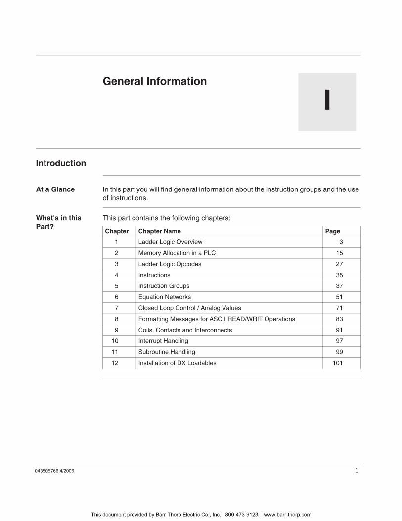
043505766 4/2006 1
IGeneral Information
Introduction
At a Glance In this part you will find general information about the instruction groups and the use of instructions.
What's in this Part?
This part contains the following chapters:
Chapter Chapter Name Page
1 Ladder Logic Overview 3
2 Memory Allocation in a PLC 15
3 Ladder Logic Opcodes 27
4 Instructions 35
5 Instruction Groups 37
6 Equation Networks 51
7 Closed Loop Control / Analog Values 71
8 Formatting Messages for ASCII READ/WRIT Operations 83
9 Coils, Contacts and Interconnects 91
10 Interrupt Handling 97
11 Subroutine Handling 99
12 Installation of DX Loadables 101
This document provided by Barr-Thorp Electric Co., Inc. 800-473-9123 www.barr-thorp.com

General Information
2 043505766 4/2006
This document provided by Barr-Thorp Electric Co., Inc. 800-473-9123 www.barr-thorp.com
043505766 4/2006 3
1Ladder Logic Overview
At a Glance
Overview This chapter provides an overview of the Ladder Logic programming language.
What's in this Chapter?
This chapter contains the following topics:
Topic Page
Segments and Networks in Ladder Logic 4
How a PLC Solves Ladder Logic 7
Ladder Logic Elements and Instructions 8
This document provided by Barr-Thorp Electric Co., Inc. 800-473-9123 www.barr-thorp.com
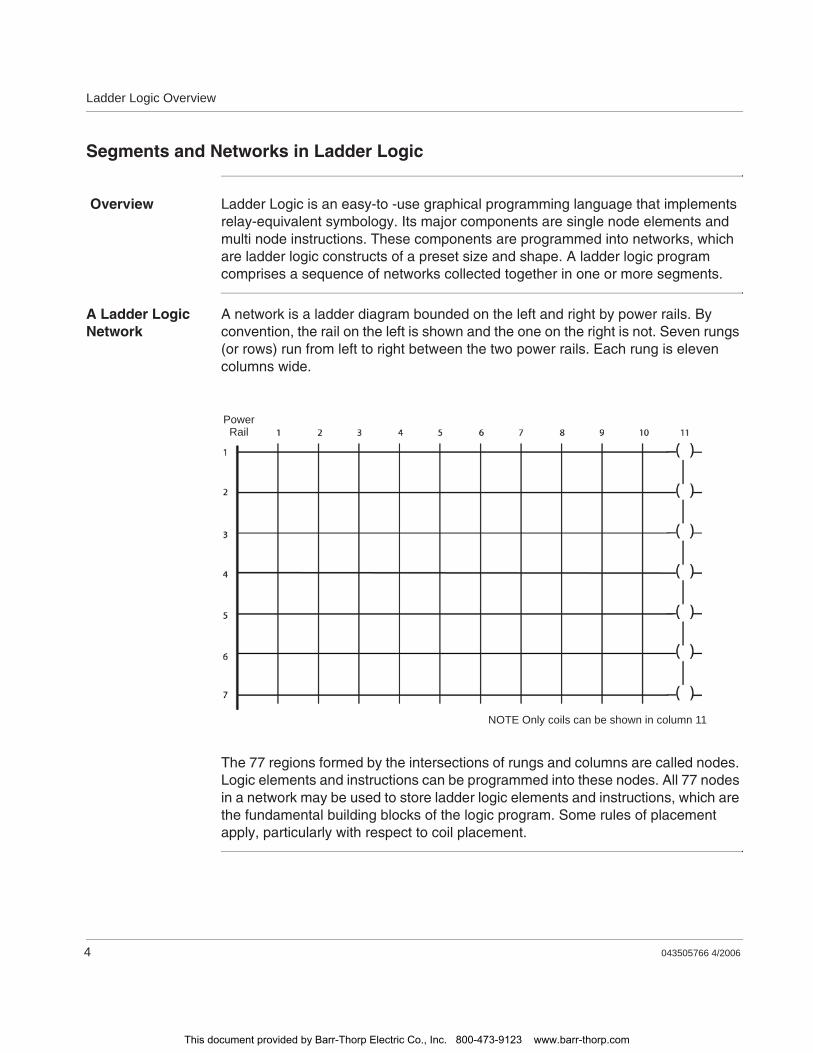
Ladder Logic Overview
4 043505766 4/2006
Segments and Networks in Ladder Logic
Overview Ladder Logic is an easy-to -use graphical programming language that implements relay-equivalent symbology. Its major components are single node elements and multi node instructions. These components are programmed into networks, which are ladder logic constructs of a preset size and shape. A ladder logic program comprises a sequence of networks collected together in one or more segments.
A Ladder Logic Network
A network is a ladder diagram bounded on the left and right by power rails. By convention, the rail on the left is shown and the one on the right is not. Seven rungs (or rows) run from left to right between the two power rails. Each rung is eleven columns wide.
The 77 regions formed by the intersections of rungs and columns are called nodes. Logic elements and instructions can be programmed into these nodes. All 77 nodes in a network may be used to store ladder logic elements and instructions, which are the fundamental building blocks of the logic program. Some rules of placement apply, particularly with respect to coil placement.
PowerRail
NOTE Only coils can be shown in column 11
This document provided by Barr-Thorp Electric Co., Inc. 800-473-9123 www.barr-thorp.com
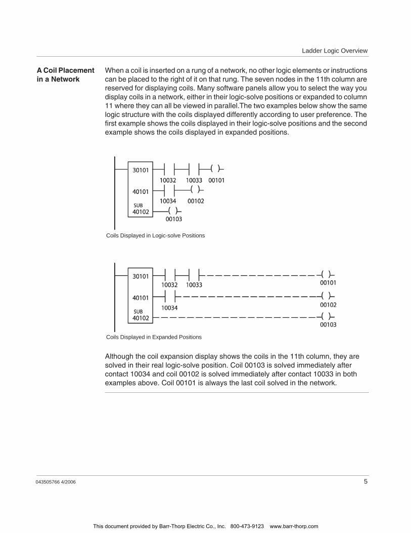
Ladder Logic Overview
043505766 4/2006 5
A Coil Placement in a Network
When a coil is inserted on a rung of a network, no other logic elements or instructions can be placed to the right of it on that rung. The seven nodes in the 11th column are reserved for displaying coils. Many software panels allow you to select the way you display coils in a network, either in their logic-solve positions or expanded to column 11 where they can all be viewed in parallel.The two examples below show the same logic structure with the coils displayed differently according to user preference. The first example shows the coils displayed in their logic-solve positions and the second example shows the coils displayed in expanded positions.
Although the coil expansion display shows the coils in the 11th column, they are solved in their real logic-solve position. Coil 00103 is solved immediately after contact 10034 and coil 00102 is solved immediately after contact 10033 in both examples above. Coil 00101 is always the last coil solved in the network.
Coils Displayed in Logic-solve Positions
Coils Displayed in Expanded Positions
This document provided by Barr-Thorp Electric Co., Inc. 800-473-9123 www.barr-thorp.com
Ladder Logic Overview
6 043505766 4/2006
Ladder Logic Segments
Because the structure of a network is fixed, the logic program generally overlaps into multiple networks. A group of contiguous networks performing a task or subtask in the application program is called a segment. There is no prescribed limit on the number of networks that can be placed in a segment—size is limited only by the amount of UserMemory available and by the maximum amount of PLC scan time(250 ms).For small ladder logic applications, a single segment may be sufficient to store the whole program. For larger applications, such as multi-drop remote I/O applications, several segments may be programmed. As arule in RIO configurations, the number of segments in the program equals the number of I/O drops; you may want to use more segments than drops, but never fewer segments than drops.Segments are numbered 1 ... n, up to a maximum of 32, in the order they are created by the programmer. You may modify the order in which segments are solved with the segment scheduler, an editor available with your panel software that allows you to adjust the order-of-solve table in system memory. Refer to Appendix A for a description of how to improve system performance via the segment scheduler.With some PLCs, you may also create an unscheduled segment that contains one or more ladder logic subroutines, which can be called from the scheduled segments via the JSR function.
This document provided by Barr-Thorp Electric Co., Inc. 800-473-9123 www.barr-thorp.com
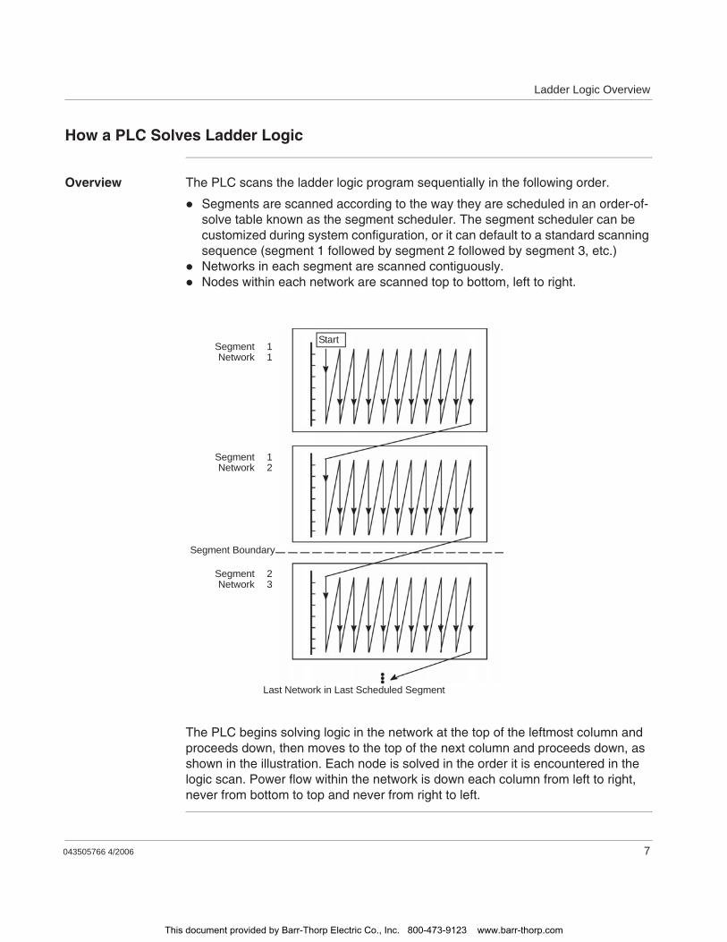
Ladder Logic Overview
043505766 4/2006 7
How a PLC Solves Ladder Logic
Overview The PLC scans the ladder logic program sequentially in the following order.
Segments are scanned according to the way they are scheduled in an order-of-solve table known as the segment scheduler. The segment scheduler can be customized during system configuration, or it can default to a standard scanning sequence (segment 1 followed by segment 2 followed by segment 3, etc.)Networks in each segment are scanned contiguously.Nodes within each network are scanned top to bottom, left to right.
The PLC begins solving logic in the network at the top of the leftmost column and proceeds down, then moves to the top of the next column and proceeds down, as shown in the illustration. Each node is solved in the order it is encountered in the logic scan. Power flow within the network is down each column from left to right, never from bottom to top and never from right to left.
SegmentNetwork
11
SegmentNetwork
12
SegmentNetwork
23
Segment Boundary
Start
Last Network in Last Scheduled Segment
This document provided by Barr-Thorp Electric Co., Inc. 800-473-9123 www.barr-thorp.com
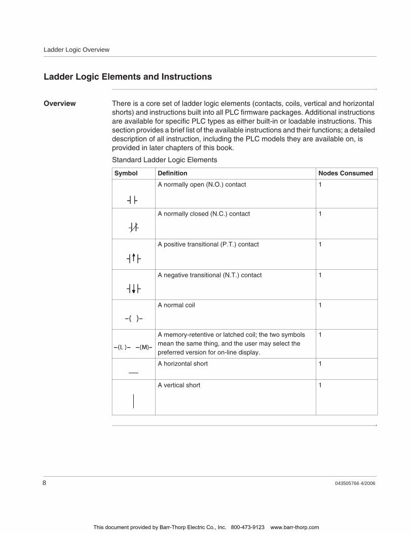
Ladder Logic Overview
8 043505766 4/2006
Ladder Logic Elements and Instructions
Overview There is a core set of ladder logic elements (contacts, coils, vertical and horizontal shorts) and instructions built into all PLC firmware packages. Additional instructions are available for specific PLC types as either built-in or loadable instructions. This section provides a brief list of the available instructions and their functions; a detailed description of all instruction, including the PLC models they are available on, is provided in later chapters of this book.
Standard Ladder Logic Elements
Symbol Definition Nodes Consumed
A normally open (N.O.) contact 1
A normally closed (N.C.) contact 1
A positive transitional (P.T.) contact 1
A negative transitional (N.T.) contact 1
A normal coil 1
A memory-retentive or latched coil; the two symbols mean the same thing, and the user may select the preferred version for on-line display.
1
A horizontal short 1
A vertical short 1
This document provided by Barr-Thorp Electric Co., Inc. 800-473-9123 www.barr-thorp.com
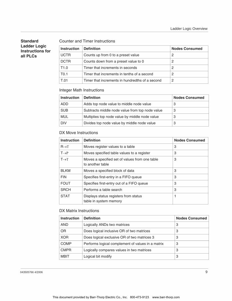
Ladder Logic Overview
043505766 4/2006 9
Standard Ladder Logic Instructions for all PLCs
Counter and Timer Instructions
Integer Math Instructions
DX Move Instructions
DX Matrix Instructions
Instruction Definition Nodes Consumed
UCTR Counts up from 0 to a preset value 2
DCTR Counts down from a preset value to 0 2
T1.0 Timer that increments in seconds 2
T0.1 Timer that increments in tenths of a second 2
T.01 Timer that increments in hundredths of a second 2
Instruction Definition Nodes Consumed
ADD Adds top node value to middle node value 3
SUB Subtracts middle node value from top node value 3
MUL Multiplies top node value by middle node value 3
DIV Divides top node value by middle node value 3
Instruction Definition Nodes Consumed
R Moves register values to a table 3
T Moves specified table values to a register 3
T Moves a specified set of values from one table to another table
3
BLKM Moves a specified block of data 3
FIN Specifies first-entry in a FIFO queue 3
FOUT Specifies first-entry out of a FIFO queue 3
SRCH Performs a table search 3
STAT Displays status registers from status table in system memory
1
Instruction Definition Nodes Consumed
AND Logically ANDs two matrices 3
OR Does logical inclusive OR of two matrices 3
XOR Does logical exclusive OR of two matrices 3 3
COMP Performs logical complement of values in a matrix 3
CMPR Logically compares values in two matrices 3
MBIT Logical bit modify 3
This document provided by Barr-Thorp Electric Co., Inc. 800-473-9123 www.barr-thorp.com
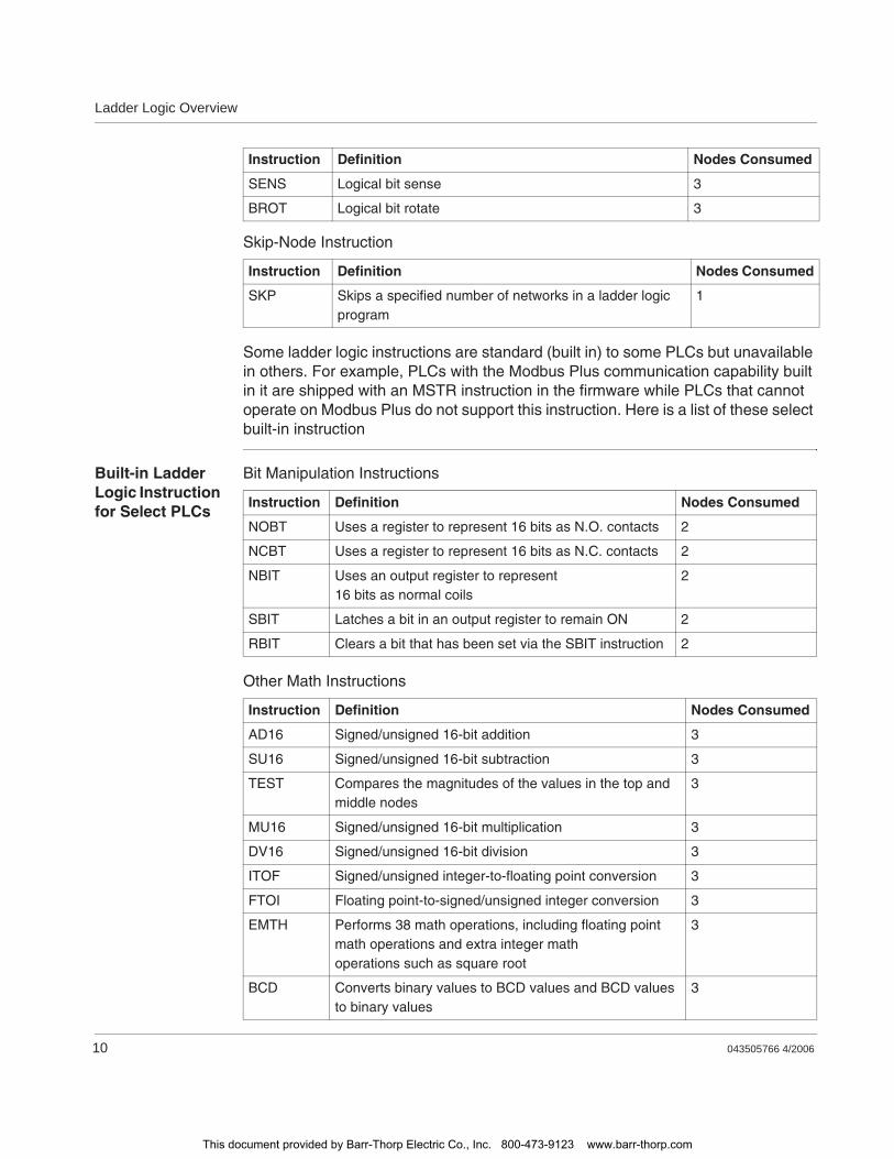
Ladder Logic Overview
10 043505766 4/2006
Skip-Node Instruction
Some ladder logic instructions are standard (built in) to some PLCs but unavailable in others. For example, PLCs with the Modbus Plus communication capability built in it are shipped with an MSTR instruction in the firmware while PLCs that cannot operate on Modbus Plus do not support this instruction. Here is a list of these select built-in instruction
Built-in Ladder Logic Instruction for Select PLCs
Bit Manipulation Instructions
Other Math Instructions
SENS Logical bit sense 3
BROT Logical bit rotate 3
Instruction Definition Nodes Consumed
SKP Skips a specified number of networks in a ladder logic program
1
Instruction Definition Nodes Consumed
Instruction Definition Nodes Consumed
NOBT Uses a register to represent 16 bits as N.O. contacts 2
NCBT Uses a register to represent 16 bits as N.C. contacts 2
NBIT Uses an output register to represent 16 bits as normal coils
2
SBIT Latches a bit in an output register to remain ON 2
RBIT Clears a bit that has been set via the SBIT instruction 2
Instruction Definition Nodes Consumed
AD16 Signed/unsigned 16-bit addition 3
SU16 Signed/unsigned 16-bit subtraction 3
TEST Compares the magnitudes of the values in the top and middle nodes
3
MU16 Signed/unsigned 16-bit multiplication 3
DV16 Signed/unsigned 16-bit division 3
ITOF Signed/unsigned integer-to-floating point conversion 3
FTOI Floating point-to-signed/unsigned integer conversion 3
EMTH Performs 38 math operations, including floating point math operations and extra integer math operations such as square root
3
BCD Converts binary values to BCD values and BCD values to binary values
3
This document provided by Barr-Thorp Electric Co., Inc. 800-473-9123 www.barr-thorp.com
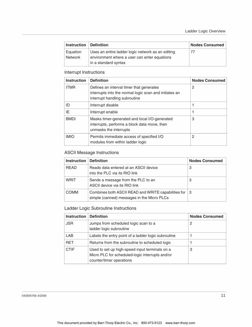
Ladder Logic Overview
043505766 4/2006 11
Interrupt Instructions
ASCII Message Instructions
Ladder Logic Subroutine Instructions
Equation Network
Uses an entire ladder logic network as an editing environment where a user can enter equations in a standard syntax
77
Instruction Definition Nodes Consumed
ITMR Defines an interval timer that generates interrupts into the normal logic scan and initiates an interrupt handling subroutine
2
ID Interrupt disable 1
IE Interrupt enable 1
BMDI Masks timer-generated and local I/O-generated interrupts, performs a block data move, then unmasks the interrupts
3
IMIO Permits immediate access of specified I/O modules from within ladder logic
2
Instruction Definition Nodes Consumed
READ Reads data entered at an ASCII device into the PLC via its RIO link
3
WRIT Sends a message from the PLC to an ASCII device via its RIO link
3
COMM Combines both ASCII READ and WRITE capabilities for simple (canned) messages in the Micro PLCs
3
Instruction Definition Nodes Consumed
JSR Jumps from scheduled logic scan to a ladder logic subroutine
2
LAB Labels the entry point of a ladder logic subroutine 1
RET Returns from the subroutine to scheduled logic 1
CTIF Used to set up high-speed input terminals on a Micro PLC for scheduled-logic interrupts and/or counter/timer operations
3
Instruction Definition Nodes Consumed
This document provided by Barr-Thorp Electric Co., Inc. 800-473-9123 www.barr-thorp.com
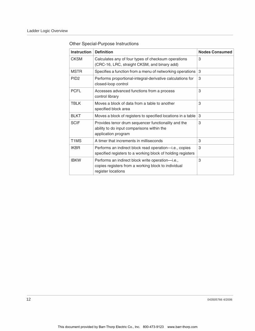
Ladder Logic Overview
12 043505766 4/2006
Other Special-Purpose Instructions
Instruction Definition Nodes Consumed
CKSM Calculates any of four types of checksum operations (CRC-16, LRC, straight CKSM, and binary add)
3
MSTR Specifies a function from a menu of networking operations 3
PID2 Performs proportional-integral-derivative calculations for closed-loop control
3
PCFL Accesses advanced functions from a process control library
3
TBLK Moves a block of data from a table to another specified block area
3
BLKT Moves a block of registers to specified locations in a table 3
SCIF Provides tenor drum sequencer functionality and the ability to do input comparisons within the application program
3
T1MS A timer that increments in milliseconds 3
IKBR Performs an indirect block read operation—i.e., copies specified registers to a working block of holding registers
3
IBKW Performs an indirect block write operation—i.e., copies registers from a working block to individual register locations
3
This document provided by Barr-Thorp Electric Co., Inc. 800-473-9123 www.barr-thorp.com
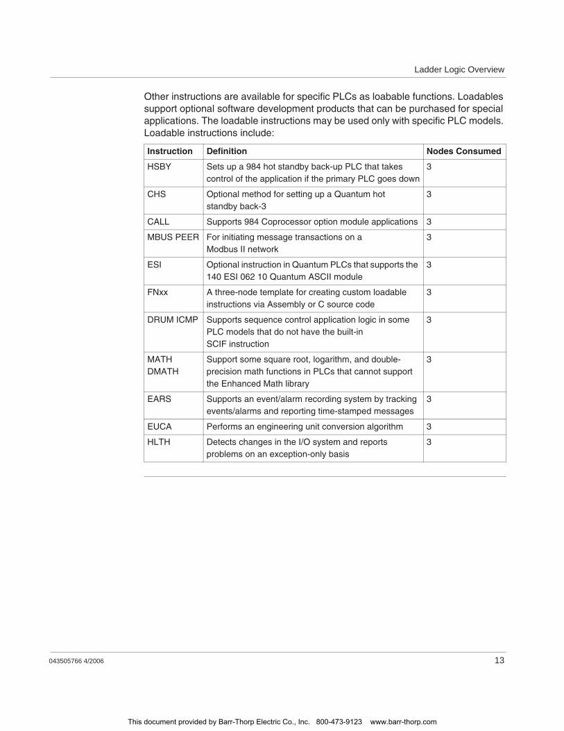
Ladder Logic Overview
043505766 4/2006 13
Other instructions are available for specific PLCs as loabable functions. Loadables support optional software development products that can be purchased for special applications. The loadable instructions may be used only with specific PLC models. Loadable instructions include:
Instruction Definition Nodes Consumed
HSBY Sets up a 984 hot standby back-up PLC that takes control of the application if the primary PLC goes down
3
CHS Optional method for setting up a Quantum hot standby back-3
3
CALL Supports 984 Coprocessor option module applications 3
MBUS PEER For initiating message transactions on a Modbus II network
3
ESI Optional instruction in Quantum PLCs that supports the 140 ESI 062 10 Quantum ASCII module
3
FNxx A three-node template for creating custom loadable instructions via Assembly or C source code
3
DRUM ICMP Supports sequence control application logic in some PLC models that do not have the built-in SCIF instruction
3
MATH DMATH
Support some square root, logarithm, and double-precision math functions in PLCs that cannot support the Enhanced Math library
3
EARS Supports an event/alarm recording system by tracking events/alarms and reporting time-stamped messages
3
EUCA Performs an engineering unit conversion algorithm 3
HLTH Detects changes in the I/O system and reports problems on an exception-only basis
3
This document provided by Barr-Thorp Electric Co., Inc. 800-473-9123 www.barr-thorp.com

Ladder Logic Overview
14 043505766 4/2006
This document provided by Barr-Thorp Electric Co., Inc. 800-473-9123 www.barr-thorp.com

043505766 4/2006 15
2Memory Allocation in a PLC
At a Glance
Overview This chapter discusses memory allocation in a PLC.
What's in this Chapter?
This chapter contains the following topics:
Topic Page
User Memory 16
State RAM Values 18
State RAM Structure 20
The Configuration Table 22
The I/O Map Table 26
This document provided by Barr-Thorp Electric Co., Inc. 800-473-9123 www.barr-thorp.com
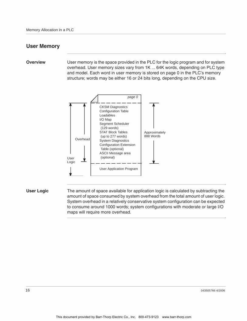
Memory Allocation in a PLC
16 043505766 4/2006
User Memory
Overview User memory is the space provided in the PLC for the logic program and for system overhead. User memory sizes vary from 1K ... 64K words, depending on PLC type and model. Each word in user memory is stored on page 0 in the PLC’s memory structure; words may be either 16 or 24 bits long, depending on the CPU size.
User Logic The amount of space available for application logic is calculated by subtracting the amount of space consumed by system overhead from the total amount of user logic. System overhead in a relatively conservative system configuration can be expected to consume around 1000 words; system configurations with moderate or large I/O maps will require more overhead.
CKSM DiagnosticsConfiguration TableLoadablesI/O MapSegment Scheduler(129 words)
STAT Block Tables(up to 277 words)
System DiagnosticsConfiguration ExtensionTable (optional)
ASCII Message area(optional)
User Application Program
Overhead
UserLogic
Approximately888 Words
page 0
This document provided by Barr-Thorp Electric Co., Inc. 800-473-9123 www.barr-thorp.com
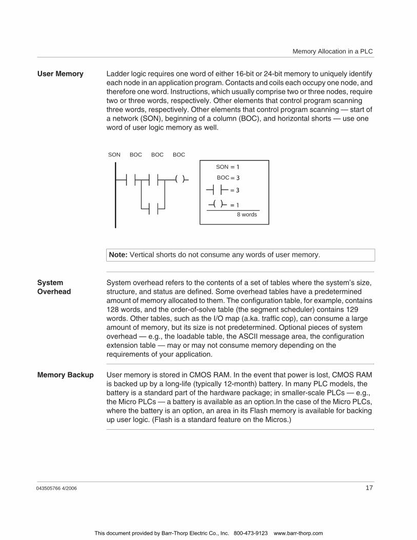
Memory Allocation in a PLC
043505766 4/2006 17
User Memory Ladder logic requires one word of either 16-bit or 24-bit memory to uniquely identify each node in an application program. Contacts and coils each occupy one node, and therefore one word. Instructions, which usually comprise two or three nodes, require two or three words, respectively. Other elements that control program scanning three words, respectively. Other elements that control program scanning — start of a network (SON), beginning of a column (BOC), and horizontal shorts — use one word of user logic memory as well.
System Overhead
System overhead refers to the contents of a set of tables where the system’s size, structure, and status are defined. Some overhead tables have a predetermined amount of memory allocated to them. The configuration table, for example, contains 128 words, and the order-of-solve table (the segment scheduler) contains 129 words. Other tables, such as the I/O map (a.ka. traffic cop), can consume a large amount of memory, but its size is not predetermined. Optional pieces of system overhead — e.g., the loadable table, the ASCII message area, the configuration extension table — may or may not consume memory depending on the requirements of your application.
Memory Backup User memory is stored in CMOS RAM. In the event that power is lost, CMOS RAM is backed up by a long-life (typically 12-month) battery. In many PLC models, the battery is a standard part of the hardware package; in smaller-scale PLCs — e.g., the Micro PLCs — a battery is available as an option.In the case of the Micro PLCs, where the battery is an option, an area in its Flash memory is available for backing up user logic. (Flash is a standard feature on the Micros.)
Note: Vertical shorts do not consume any words of user memory.
SON BOC BOC BOC
SON
BOC
8 words
This document provided by Barr-Thorp Electric Co., Inc. 800-473-9123 www.barr-thorp.com
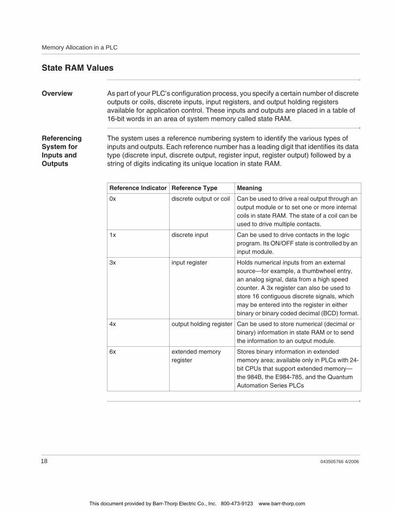
Memory Allocation in a PLC
18 043505766 4/2006
State RAM Values
Overview As part of your PLC’s configuration process, you specify a certain number of discrete outputs or coils, discrete inputs, input registers, and output holding registers available for application control. These inputs and outputs are placed in a table of 16-bit words in an area of system memory called state RAM.
Referencing System for Inputs and Outputs
The system uses a reference numbering system to identify the various types of inputs and outputs. Each reference number has a leading digit that identifies its data type (discrete input, discrete output, register input, register output) followed by a string of digits indicating its unique location in state RAM.
Reference Indicator Reference Type Meaning
0x discrete output or coil Can be used to drive a real output through an output module or to set one or more internal coils in state RAM. The state of a coil can be used to drive multiple contacts.
1x discrete input Can be used to drive contacts in the logic program. Its ON/OFF state is controlled by an input module.
3x input register Holds numerical inputs from an external source—for example, a thumbwheel entry, an analog signal, data from a high speed counter. A 3x register can also be used to store 16 contiguous discrete signals, which may be entered into the register in either binary or binary coded decimal (BCD) format.
4x output holding register Can be used to store numerical (decimal or binary) information in state RAM or to send the information to an output module.
6x extended memory register
Stores binary information in extended memory area; available only in PLCs with 24-bit CPUs that support extended memory—the 984B, the E984-785, and the Quantum Automation Series PLCs
This document provided by Barr-Thorp Electric Co., Inc. 800-473-9123 www.barr-thorp.com
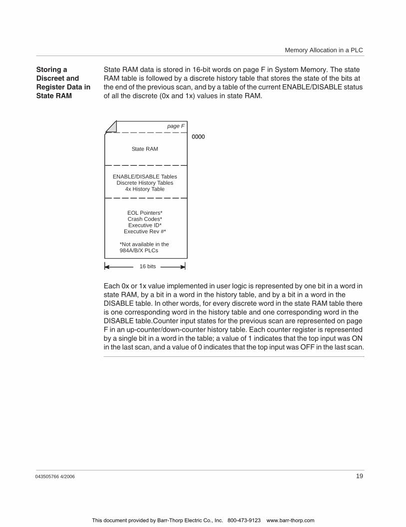
Memory Allocation in a PLC
043505766 4/2006 19
Storing a Discreet and Register Data in State RAM
State RAM data is stored in 16-bit words on page F in System Memory. The state RAM table is followed by a discrete history table that stores the state of the bits at the end of the previous scan, and by a table of the current ENABLE/DISABLE status of all the discrete (0x and 1x) values in state RAM.
Each 0x or 1x value implemented in user logic is represented by one bit in a word in state RAM, by a bit in a word in the history table, and by a bit in a word in the DISABLE table. In other words, for every discrete word in the state RAM table there is one corresponding word in the history table and one corresponding word in the DISABLE table.Counter input states for the previous scan are represented on page F in an up-counter/down-counter history table. Each counter register is represented by a single bit in a word in the table; a value of 1 indicates that the top input was ON in the last scan, and a value of 0 indicates that the top input was OFF in the last scan.
State RAM
ENABLE/DISABLE TablesDiscrete History Tables
4x History Table
EOL Pointers*Crash Codes*Executive ID*
Executive Rev #*
*Not available in the984A/B/X PLCs
16 bits
page F
This document provided by Barr-Thorp Electric Co., Inc. 800-473-9123 www.barr-thorp.com
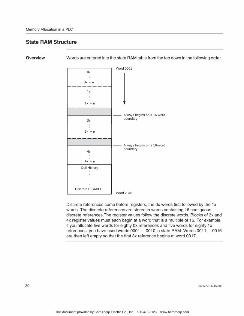
Memory Allocation in a PLC
20 043505766 4/2006
State RAM Structure
Overview Words are entered into the state RAM table from the top down in the following order.
Discrete references come before registers, the 0x words first followed by the 1x words. The discrete references are stored in words containing 16 contiguous discrete references.The register values follow the discrete words. Blocks of 3x and 4x register values must each begin at a word that is a multiple of 16. For example, if you allocate five words for eighty 0x references and five words for eighty 1x references, you have used words 0001 ... 0010 in state RAM. Words 0011 ... 0016 are then left empty so that the first 3x reference begins at word 0017.
Word 0001
Always begins on a 16-word boundary
Always begins on a 16-word boundary
Word 2048
Coil History
Discrete DISABLE
This document provided by Barr-Thorp Electric Co., Inc. 800-473-9123 www.barr-thorp.com

Memory Allocation in a PLC
043505766 4/2006 21
Minimum Required State RAM Values
A minimum configuration consists of the following allocations in state RAM.
History and Disable Bits for Discrete References
For each word allocated to discrete references, two additional words are allocated in the history/disable tables. These tables follow the state RAM table on page F in system memory. They are generated from the bottom up in the following manner.
Reference Type Minimum Words for Modsoft
Minimum Words for P190
Minimum Bits for Modsoft
Minimum Bits for discretes
Discrete out (0X) 3 1 48 16
Discrete in (1x) 1 1 16 16
Register in (3x) 1 1
Register out (4x) 1 1
Output History Bits
Input History Bits
Output DISABLE Bits
Input DISABLE Bits
Word 0001
Word 2048
This document provided by Barr-Thorp Electric Co., Inc. 800-473-9123 www.barr-thorp.com
Memory Allocation in a PLC
22 043505766 4/2006
The Configuration Table
Overview The configuration table is one of the key pieces of overhead contained in system memory. It comprises 128 consecutive words and provides a means of accessing information defining your control system capabilities and your user logic program.
With your programming panel software, you can access the configurator editor, which allows you to specify the configuration parameters — such as those shown on the following page — for your control system.When a PLC’s memory is empty — in a state called DIM AWARENESS — you are not able to write a I/O map or a user logic program. Therefore, the first programming task you must undertake with a new PLC is to write a valid configuration table using your configurator editor.
Assigning a Battery Coil
A 0x coil can be set aside in the configuration to reflect the current status of the PLC’s battery backup system. If this coil has been set and is queried, it displays a discrete value of either 0, indicating that the battery system is healthy, or 1 indicating the battery system is not healthy.
Assigning Timer Register
A 4x register can be set aside in the configuration as a synchronization timer. It stores a count of clock cycles in 10 ms increments. If this register is set and queried, it displays a free-running value that ranges from 0000 to FFFF hex with wrap-around to 0000.
Note: If you are doing explicit address routing in bridge mode on a Modbus Plus network, the location of the explicit address table in the configuration is dependent on the timer register address—i.e., a timer register must be assigned in order to create the explicit address table. The explicit address table can consist of from 0 ... 10 blocks, each block containing five consecutive 4x registers. The address of the first block in the explicit address table begins with the 4x register immediately following the address assigned to the timer register. Therefore, when you assign the timer register, you must choose a 4x register address that has the next 5 ... 50 registers free for this kind of application.
This document provided by Barr-Thorp Electric Co., Inc. 800-473-9123 www.barr-thorp.com

Memory Allocation in a PLC
043505766 4/2006 23
Time of Day Clock
When a 4x holding register assignment is made in the configurator for the time of day (TOD) clock, that register and the next seven consecutive registers (4x ... 4x + 7) are set aside in the configuration to store TOD information. The block of registers is implemented as follows.
The block of registers is implemented as follows. For example, if you configured register 40500 for your TOD clock, set the bits appropriately as shown above, then read the clock values at 9:25:30 on Tuesday, July 16, 1991, the register values displayed in decimal format would read:
Register Definition
4X
4X+1 Day of the week (Sunday = 1, Monday = 2, etc.)
4x+2 Month of the year (Jan. = 1, Feb. = 2, etc.)
4x+3 Day of the month (1... 31)
4x+4 Year (00... 99)
4x+5 Hour in military time (0... 23)
4x+6 Minute (0... 59)
4x+7 Second (0... 59) When a 4x holding register assignment is made in the configurator for the time of day (TOD) clock, that register and the next seven consecutive registers (4x... 4x + 7) are set aside in the configuration to store TOD information.
Register Definition
400500 0110000000000000
400501 3 (decimal)
400502 7 (decimal)
400503 16 (decimal)
400504 91 (decimal)
400505 9 (decimal)
400506 25 (decimal
400507 30 (decimal)
1 = error
1 = clock values are being read1 = clock values are being set
The control register:
1 = all clock values have been set
This document provided by Barr-Thorp Electric Co., Inc. 800-473-9123 www.barr-thorp.com
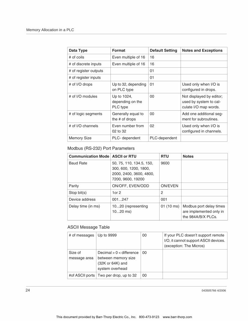
Memory Allocation in a PLC
24 043505766 4/2006
Modbus (RS-232) Port Parameters
ASCII Message Table
Data Type Format Default Setting Notes and Exceptions
# of coils Even multiple of 16 16
# of discrete inputs Even multiple of 16 16
# of register outputs 01
# of register inputs 01
# of I/O drops Up to 32, depending on PLC type
01 Used only when I/O is configured in drops.
# of I/O modules Up to 1024, depending on the PLC type
00 Not displayed by editor; used by system to cal-culate I/O map words.
# of logic segments Generally equal to the # of drops
00 Add one additional seg-ment for subroutines.
# of I/O channels Even number from 02 to 32
02 Used only when I/O is configured in channels.
Memory Size PLC- dependent PLC-dependent
Communication Mode ASCII or RTU RTU Notes
Baud Rate 50, 75, 110, 134.5, 150, 300, 600, 1200, 1800, 2000, 2400, 3600, 4800, 7200, 9600, 19200
9600
Parity ON/OFF, EVEN/ODD ON/EVEN
Stop bit(s) 1or 2 2
Device address 001...247 001
Delay time (in ms) 10...20 (representing 10...20 ms)
01 (10 ms) Modbus port delay times are implemented only in the 984A/B/X PLCs.
# of messages Up to 9999 00 If your PLC doesn’t support remote I/O, it cannot support ASCII devices. (exception: The Micros)
Size of message area
Decimal > 0 < difference between memory size (32K or 64K) and system overhead
00
#of ASCII ports Two per drop, up to 32 00
This document provided by Barr-Thorp Electric Co., Inc. 800-473-9123 www.barr-thorp.com
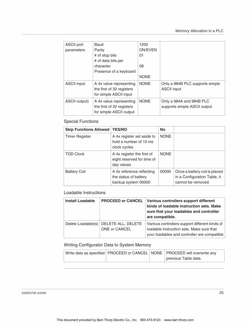
Memory Allocation in a PLC
043505766 4/2006 25
Special Functions
Loadable Instructions
Writing Configurator Data to System Memory
ASCII port parameters
BaudParity# of stop bits# of data bits per characterPresence of a keyboard
1200ON/EVEN01
08
NONE
ASCII input A 4x value representing the first of 32 registers for simple ASCII input
NONE Only a 984B PLC supports simple ASCII input
ASCII output) A 4x value representing the first of 32 registers for simple ASCII output
NONE Only a 984A and 984B PLC supports simple ASCII output
Skip Functions Allowed YES/NO No
Timer Register A 4x register set aside to hold a number of 10 ms clock cycles
NONE
TOD Clock A 4x register the first of eight reserved for time of day values
NONE
Battery Coil A 0x reference reflecting the status of battery backup system 00000
00000 Once a battery coil is placed in a Configuration Table, it cannot be removed.
Install Loadable PROCEED or CANCEL Various controllers support different kinds of loadable instruction sets. Make sure that your loadables and controller are compatible.
Delete Loadable(s) DELETE ALL, DELETE ONE or CANCEL
Various controllers support different kinds of loadable instruction sets. Make sure that your loadables and controller are compatible
Write data as specified PROCEED or CANCEL NONE PROCEED will overwrite any previous Table data.
This document provided by Barr-Thorp Electric Co., Inc. 800-473-9123 www.barr-thorp.com

Memory Allocation in a PLC
26 043505766 4/2006
The I/O Map Table
Overview Just as a PLC needs to be physically linked to I/O modules in order to become a working control system, the references in user logic need to be linked in the system architecture to the signals received from the input modules and sent to the output modules. The I/O map table provides that link.
Determining the Size of the I/O Map Table
The I/O map directs data flow between the input/output signals and the user logic program; it tells the PLC how to implement inputs in user logic and provides a pathway down which to send signals to the output modules. The I/O map table, which is stored on page 0 in system memory, consumes a large but not predetermined amount of system overhead.Its length is a function of the number of discrete and register I/O points your system has implemented and is defined by the type of I/O modules you specify in the configuration table.
The minimum allowable size of the I/O map table is nine words.
Writing Data to the I/O Map
With your programming panel software, you can access a I/O map editor that allows you to define:
the number of drops in the remote I/O system
the number of discretes/registers that may be used for input and output
the number, type and slot location of the I/O modules in the drop
the reference numbers that link the discrete/registers to the I/O modules
drop hold-up time for each I/O drop
ASCII messaging port addresses (if used) for any drop
This document provided by Barr-Thorp Electric Co., Inc. 800-473-9123 www.barr-thorp.com
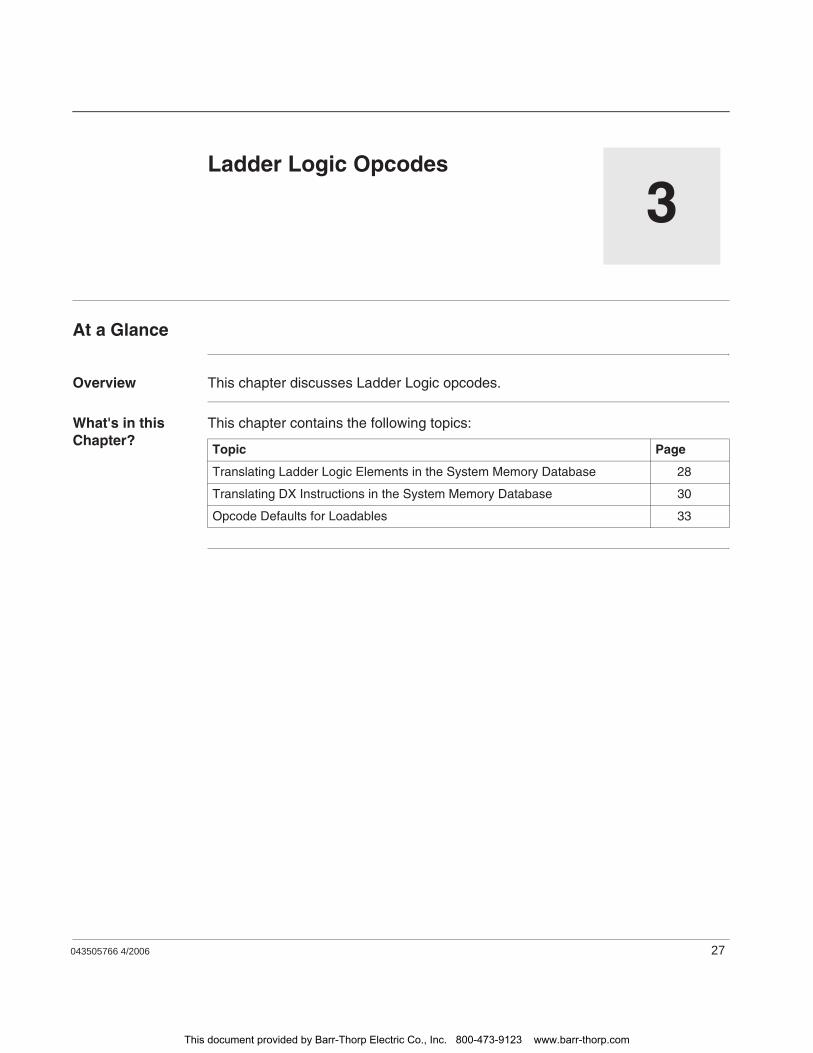
043505766 4/2006 27
3Ladder Logic Opcodes
At a Glance
Overview This chapter discusses Ladder Logic opcodes.
What's in this Chapter?
This chapter contains the following topics:
Topic Page
Translating Ladder Logic Elements in the System Memory Database 28
Translating DX Instructions in the System Memory Database 30
Opcode Defaults for Loadables 33
This document provided by Barr-Thorp Electric Co., Inc. 800-473-9123 www.barr-thorp.com
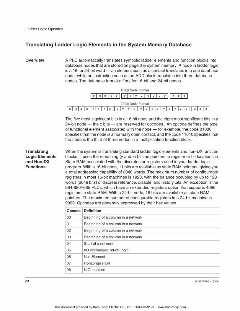
Ladder Logic Opcodes
28 043505766 4/2006
Translating Ladder Logic Elements in the System Memory Database
Overview A PLC automatically translates symbolic ladder elements and function blocks into database nodes that are stored on page 0 in system memory. A node in ladder logic is a 16- or 24-bit word — an element such as a contact translates into one database node, while an instruction such as an ADD block translates into three database nodes. The database format differs for 16-bit and 24-bit nodes.
The five most significant bits in a 16-bit node and the eight most significant bits in a 24-bit node — the x bits — are reserved for opcodes . An opcode defines the type of functional element associated with the node — for example, the code 01000 specifies that the node is a normally open contact, and the code 11010 specifies that the node is the third of three nodes in a multiplication function block.
Translating Logic Elements and Non-DX Functions
When the system is translating standard ladder logic elements and non-DX function blocks, it uses the remaining (y and z) bits as pointers to register or bit locations in State RAM associated with the discretes or registers used in your ladder logic program. With a 16-bit node, 11 bits are available as state RAM pointers, giving you a total addressing capability of 2048 words. The maximum number of configurable registers in most 16-bit machines is 1920, with the balance occupied by up to 128 words (2048 bits) of discrete reference, disable, and history bits. An exception is the 984-680/-685 PLCs, which have an extended registers option that supports 4096 registers in state RAM. With a 24-bit node, 16 bits are available as state RAM pointers. The maximum number of configurable registers in a 24-bit machine is 9999. Opcodes are generally expressed by their hex values.
16-bit Node Format
24-bit Node Format
Opcode Definition
00 Beginning of a column in a network
01 Beginning of a column in a network
02 Beginning of a column in a network
03 Beginning of a column in a network
04 Start of a network
05 I/O exchange/End-of-Logic
06 Null Element
07 Horizontal short
08 N.O. contact
This document provided by Barr-Thorp Electric Co., Inc. 800-473-9123 www.barr-thorp.com
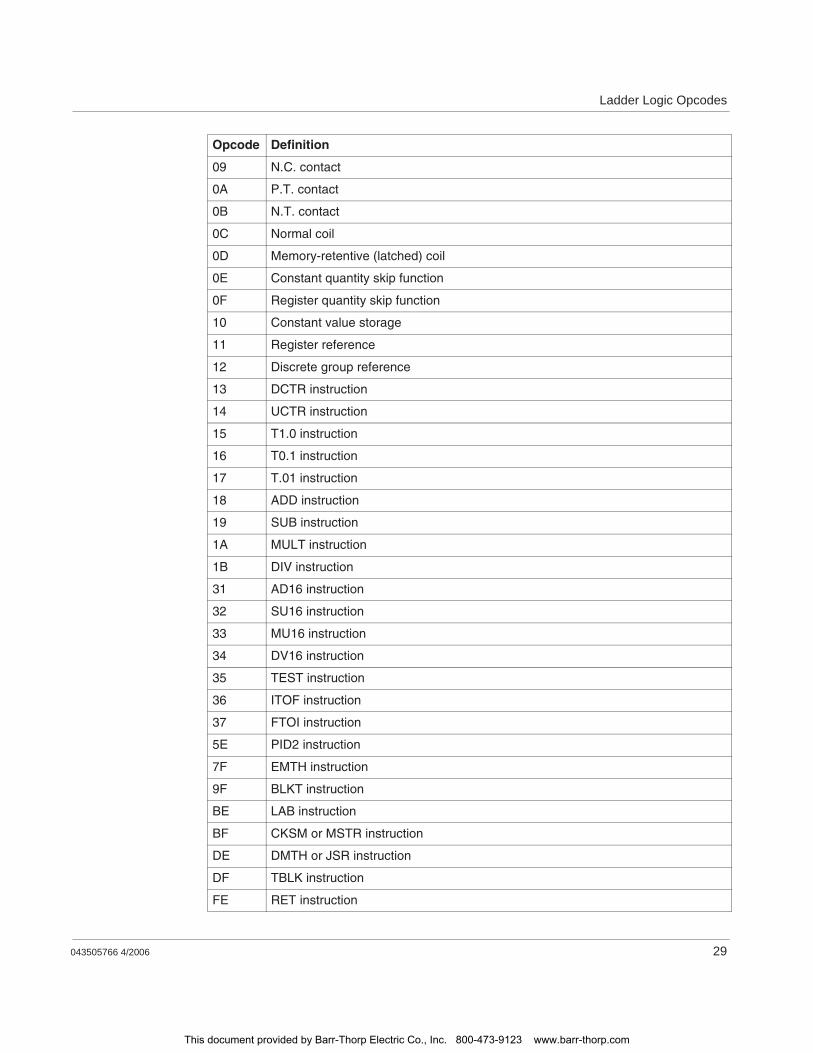
Ladder Logic Opcodes
043505766 4/2006 29
09 N.C. contact
0A P.T. contact
0B N.T. contact
0C Normal coil
0D Memory-retentive (latched) coil
0E Constant quantity skip function
0F Register quantity skip function
10 Constant value storage
11 Register reference
12 Discrete group reference
13 DCTR instruction
14 UCTR instruction
15 T1.0 instruction
16 T0.1 instruction
17 T.01 instruction
18 ADD instruction
19 SUB instruction
1A MULT instruction
1B DIV instruction
31 AD16 instruction
32 SU16 instruction
33 MU16 instruction
34 DV16 instruction
35 TEST instruction
36 ITOF instruction
37 FTOI instruction
5E PID2 instruction
7F EMTH instruction
9F BLKT instruction
BE LAB instruction
BF CKSM or MSTR instruction
DE DMTH or JSR instruction
DF TBLK instruction
FE RET instruction
Opcode Definition
This document provided by Barr-Thorp Electric Co., Inc. 800-473-9123 www.barr-thorp.com
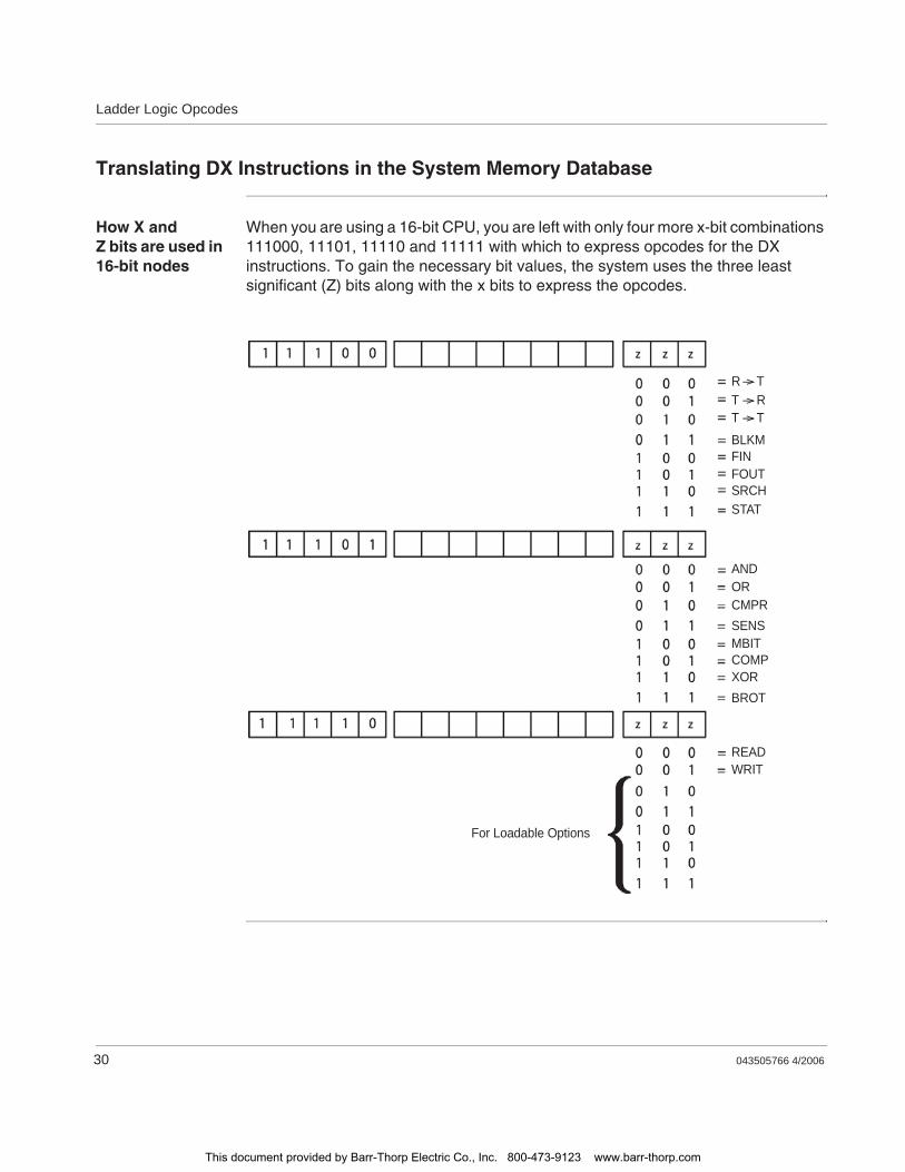
Ladder Logic Opcodes
30 043505766 4/2006
Translating DX Instructions in the System Memory Database
How X and Z bits are used in 16-bit nodes
When you are using a 16-bit CPU, you are left with only four more x-bit combinations 111000, 11101, 11110 and 11111 with which to express opcodes for the DX instructions. To gain the necessary bit values, the system uses the three least significant (Z) bits along with the x bits to express the opcodes.
R TT RT TBLKMFINFOUTSRCHSTAT
ANDORCMPRSENSMBITCOMPXORBROT
READWRIT
For Loadable Options
This document provided by Barr-Thorp Electric Co., Inc. 800-473-9123 www.barr-thorp.com
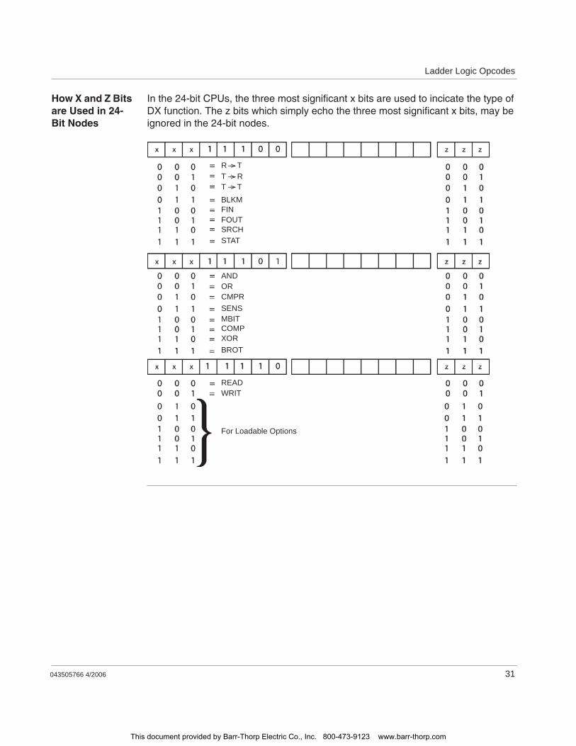
Ladder Logic Opcodes
043505766 4/2006 31
How X and Z Bits are Used in 24-Bit Nodes
In the 24-bit CPUs, the three most significant x bits are used to incicate the type of DX function. The z bits which simply echo the three most significant x bits, may be ignored in the 24-bit nodes.
R TT RT TBLKMFINFOUTSRCHSTAT
ANDORCMPRSENSMBITCOMPXORBROT
READWRIT
For Loadable Options
This document provided by Barr-Thorp Electric Co., Inc. 800-473-9123 www.barr-thorp.com
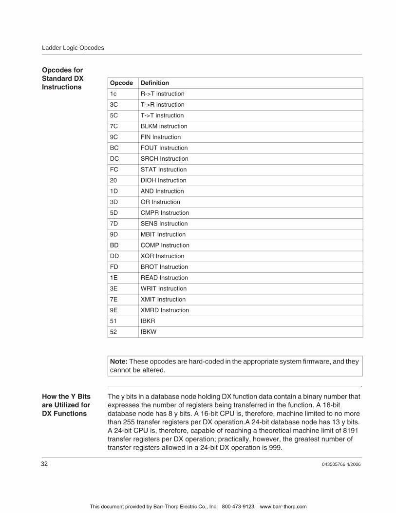
Ladder Logic Opcodes
32 043505766 4/2006
Opcodes for Standard DX Instructions
How the Y Bits are Utilized for DX Functions
The y bits in a database node holding DX function data contain a binary number that expresses the number of registers being transferred in the function. A 16-bit database node has 8 y bits. A 16-bit CPU is, therefore, machine limited to no more than 255 transfer registers per DX operation.A 24-bit database node has 13 y bits. A 24-bit CPU is, therefore, capable of reaching a theoretical machine limit of 8191 transfer registers per DX operation; practically, however, the greatest number of transfer registers allowed in a 24-bit DX operation is 999.
Opcode Definition
1c R->T instruction
3C T->R instruction
5C T->T instruction
7C BLKM instruction
9C FIN Instruction
BC FOUT Instruction
DC SRCH Instruction
FC STAT Instruction
20 DIOH Instruction
1D AND Instruction
3D OR Instruction
5D CMPR Instruction
7D SENS Instruction
9D MBIT Instruction
BD COMP Instruction
DD XOR Instruction
FD BROT Instruction
1E READ Instruction
3E WRIT Instruction
7E XMIT Instruction
9E XMRD Instruction
51 IBKR
52 IBKW
Note: These opcodes are hard-coded in the appropriate system firmware, and they cannot be altered.
This document provided by Barr-Thorp Electric Co., Inc. 800-473-9123 www.barr-thorp.com
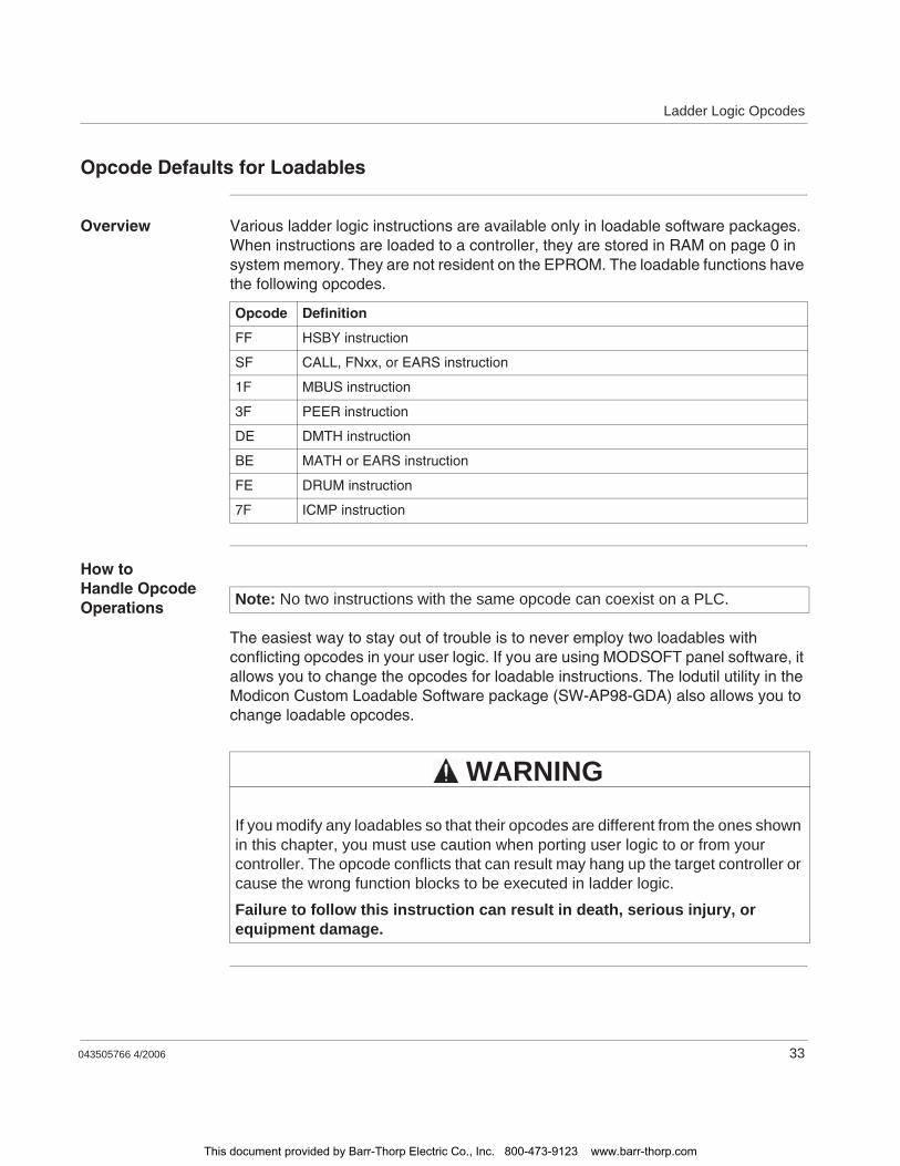
Ladder Logic Opcodes
043505766 4/2006 33
Opcode Defaults for Loadables
Overview Various ladder logic instructions are available only in loadable software packages. When instructions are loaded to a controller, they are stored in RAM on page 0 in system memory. They are not resident on the EPROM. The loadable functions have the following opcodes.
How to Handle Opcode Operations
The easiest way to stay out of trouble is to never employ two loadables with conflicting opcodes in your user logic. If you are using MODSOFT panel software, it allows you to change the opcodes for loadable instructions. The lodutil utility in the Modicon Custom Loadable Software package (SW-AP98-GDA) also allows you to change loadable opcodes.
Opcode Definition
FF HSBY instruction
SF CALL, FNxx, or EARS instruction
1F MBUS instruction
3F PEER instruction
DE DMTH instruction
BE MATH or EARS instruction
FE DRUM instruction
7F ICMP instruction
Note: No two instructions with the same opcode can coexist on a PLC.
If you modify any loadables so that their opcodes are different from the ones shown in this chapter, you must use caution when porting user logic to or from your controller. The opcode conflicts that can result may hang up the target controller or cause the wrong function blocks to be executed in ladder logic.
Failure to follow this instruction can result in death, serious injury, or equipment damage.
WARNING
This document provided by Barr-Thorp Electric Co., Inc. 800-473-9123 www.barr-thorp.com

Ladder Logic Opcodes
34 043505766 4/2006
This document provided by Barr-Thorp Electric Co., Inc. 800-473-9123 www.barr-thorp.com
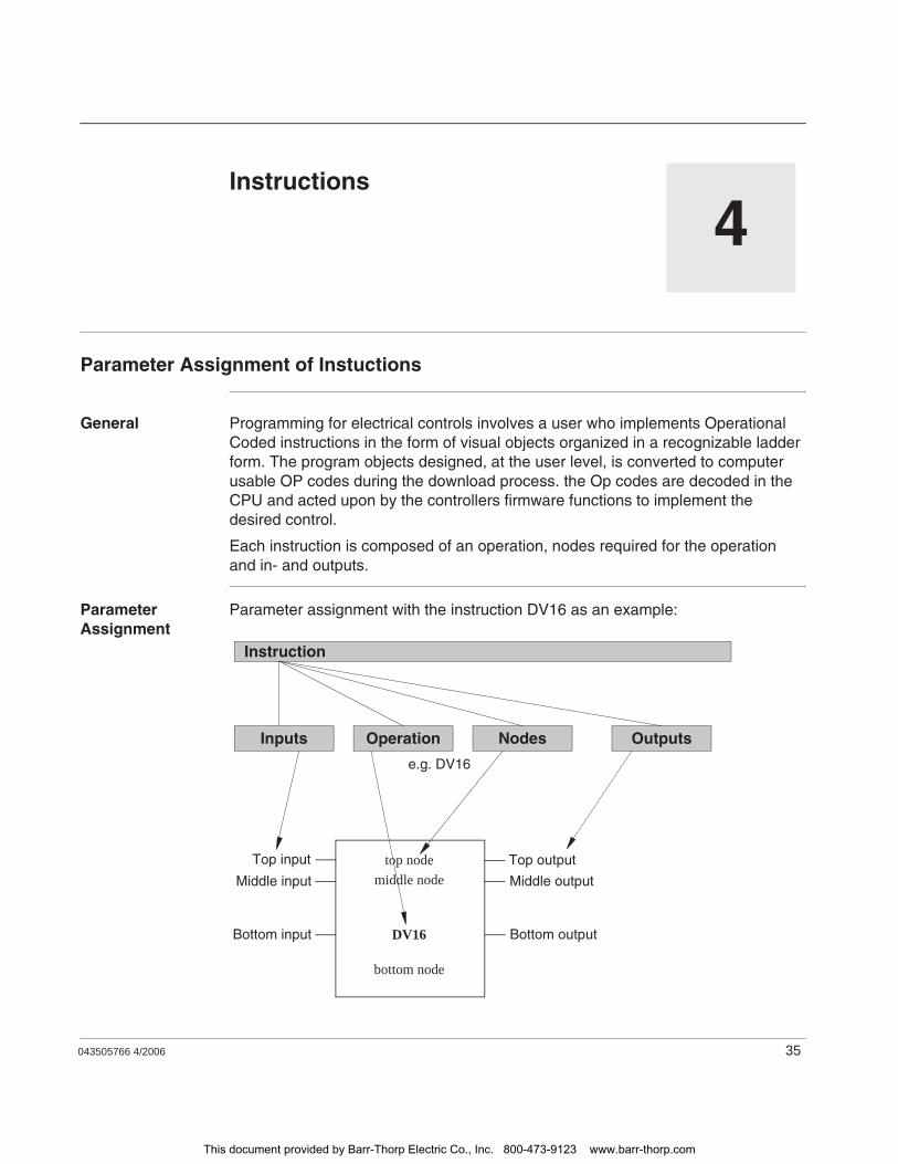
043505766 4/2006 35
4Instructions
Parameter Assignment of Instuctions
General Programming for electrical controls involves a user who implements Operational Coded instructions in the form of visual objects organized in a recognizable ladder form. The program objects designed, at the user level, is converted to computer usable OP codes during the download process. the Op codes are decoded in the CPU and acted upon by the controllers firmware functions to implement the desired control.
Each instruction is composed of an operation, nodes required for the operation and in- and outputs.
Parameter Assignment
Parameter assignment with the instruction DV16 as an example:
Instruction
Inputs Operation Nodes Outputs
Top output
Middle output
Bottom output
top nodeTop input
middle nodeMiddle input
DV16Bottom input
bottom node
e.g. DV16
This document provided by Barr-Thorp Electric Co., Inc. 800-473-9123 www.barr-thorp.com

Instructions
36 043505766 4/2006
Operation The operation determines which functionality is to be executed by the instruction, e.g. shift register, conversion operations.
Nodes, In- and Outputs
The nodes and in- and outputs determines what the operation will be executed with.
This document provided by Barr-Thorp Electric Co., Inc. 800-473-9123 www.barr-thorp.com
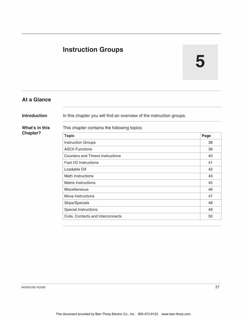
043505766 4/2006 37
5Instruction Groups
At a Glance
Introduction In this chapter you will find an overview of the instruction groups.
What's in this Chapter?
This chapter contains the following topics:
Topic Page
Instruction Groups 38
ASCII Functions 39
Counters and Timers Instructions 40
Fast I/O Instructions 41
Loadable DX 42
Math Instructions 43
Matrix Instructions 45
Miscellaneous 46
Move Instructions 47
Skips/Specials 48
Special Instructions 49
Coils, Contacts and Interconnects 50
This document provided by Barr-Thorp Electric Co., Inc. 800-473-9123 www.barr-thorp.com

Instruction Groups
38 043505766 4/2006
Instruction Groups
General All instructions are attached to one of the following groups.ASCII Functions (See p. 39)Counters/Timers (See p. 40)Fast I/O Instructions (See p. 41)Loadable DX (See p. 42)Math (See p. 43)Matrix (See p. 45)Miscellaneous (See p. 46)Move (See p. 47)Skips/Specials (See p. 48)Special (See p. 49)Coils, Contacts and Interconnects (See p. 50)
This document provided by Barr-Thorp Electric Co., Inc. 800-473-9123 www.barr-thorp.com
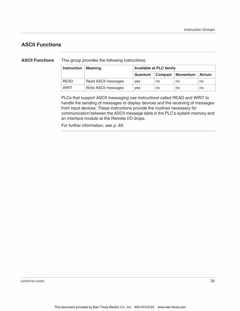
Instruction Groups
043505766 4/2006 39
ASCII Functions
ASCII Functions This group provides the following instructions.
PLCs that support ASCII messaging use instructions called READ and WRIT to handle the sending of messages to display devices and the receiving of messages from input devices. These instructions provide the routines necessary for communication between the ASCII message table in the PLC’s system memory and an interface module at the Remote I/O drops.
For further information, see p. 83.
Instruction Meaning Available at PLC family
Quantum Compact Momentum Atrium
READ Read ASCII messages yes no no no
WRIT Write ASCII messages yes no no no
This document provided by Barr-Thorp Electric Co., Inc. 800-473-9123 www.barr-thorp.com
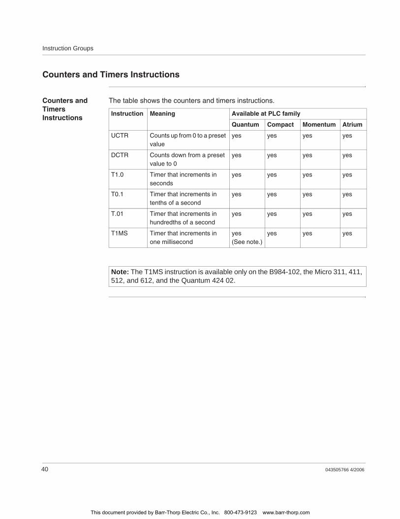
Instruction Groups
40 043505766 4/2006
Counters and Timers Instructions
Counters and Timers Instructions
The table shows the counters and timers instructions.
Instruction Meaning Available at PLC family
Quantum Compact Momentum Atrium
UCTR Counts up from 0 to a preset value
yes yes yes yes
DCTR Counts down from a preset value to 0
yes yes yes yes
T1.0 Timer that increments in seconds
yes yes yes yes
T0.1 Timer that increments in tenths of a second
yes yes yes yes
T.01 Timer that increments in hundredths of a second
yes yes yes yes
T1MS Timer that increments in one millisecond
yes(See note.)
yes yes yes
Note: The T1MS instruction is available only on the B984-102, the Micro 311, 411, 512, and 612, and the Quantum 424 02.
This document provided by Barr-Thorp Electric Co., Inc. 800-473-9123 www.barr-thorp.com
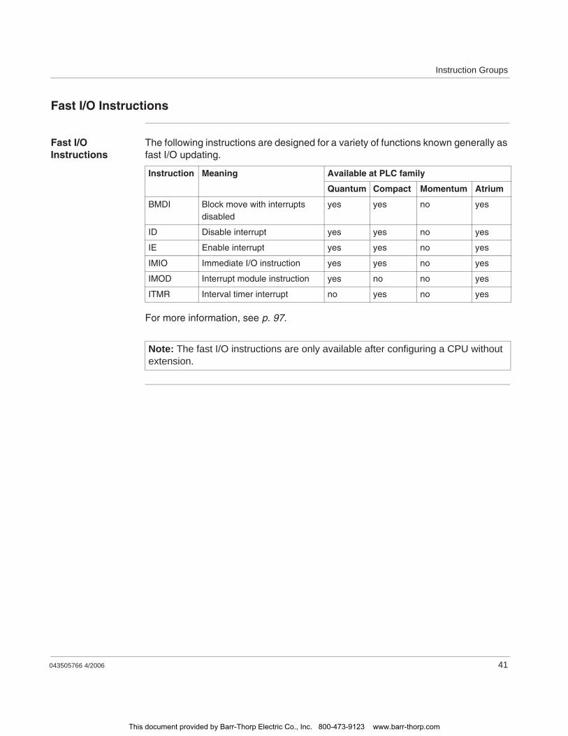
Instruction Groups
043505766 4/2006 41
Fast I/O Instructions
Fast I/O Instructions
The following instructions are designed for a variety of functions known generally as fast I/O updating.
For more information, see p. 97.
Instruction Meaning Available at PLC family
Quantum Compact Momentum Atrium
BMDI Block move with interrupts disabled
yes yes no yes
ID Disable interrupt yes yes no yes
IE Enable interrupt yes yes no yes
IMIO Immediate I/O instruction yes yes no yes
IMOD Interrupt module instruction yes no no yes
ITMR Interval timer interrupt no yes no yes
Note: The fast I/O instructions are only available after configuring a CPU without extension.
This document provided by Barr-Thorp Electric Co., Inc. 800-473-9123 www.barr-thorp.com
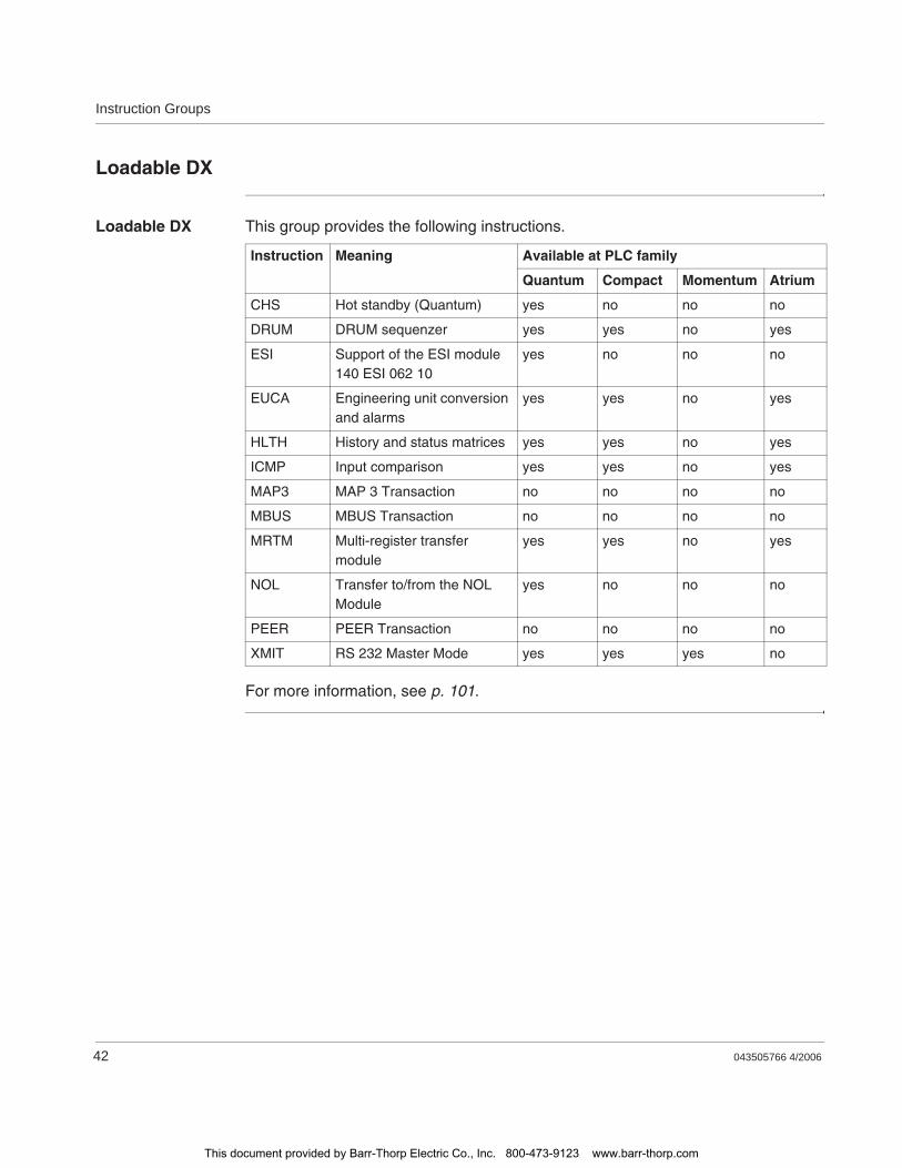
Instruction Groups
42 043505766 4/2006
Loadable DX
Loadable DX This group provides the following instructions.
For more information, see p. 101.
Instruction Meaning Available at PLC family
Quantum Compact Momentum Atrium
CHS Hot standby (Quantum) yes no no no
DRUM DRUM sequenzer yes yes no yes
ESI Support of the ESI module 140 ESI 062 10
yes no no no
EUCA Engineering unit conversion and alarms
yes yes no yes
HLTH History and status matrices yes yes no yes
ICMP Input comparison yes yes no yes
MAP3 MAP 3 Transaction no no no no
MBUS MBUS Transaction no no no no
MRTM Multi-register transfer module
yes yes no yes
NOL Transfer to/from the NOL Module
yes no no no
PEER PEER Transaction no no no no
XMIT RS 232 Master Mode yes yes yes no
This document provided by Barr-Thorp Electric Co., Inc. 800-473-9123 www.barr-thorp.com

Instruction Groups
043505766 4/2006 43
Math Instructions
Math Instructions
Two groups of instructions that support basic math operations are available. The first group comprises four integer-based instructions: ADD, SUB, MUL and DIV.
The second group contains five comparable instructions, AD16, SU16, TEST, MU16 and DV16, that support signed and unsigned 16-bit math calculations and comparisons.
Three additional instructions, ITOF, FTOI and BCD, are provided to convert the formats of numerical values (from integer to floating point, floating point to integer, binary to BCD and BCD to binary). Conversion operations are usful in expanded math.
Integer Based Instructions
This part of the group provides the following instructions.
Comparable Instructions
This part of the group provides the following instructions.
Instruction Meaning Available at PLC family
Quantum Compact Momentum Atrium
ADD Addition yes yes yes yes
DIV Division yes yes yes yes
MUL Multiplication yes yes yes yes
SUB Subtraction yes yes yes yes
Instruction Meaning Available at PLC family
Quantum Compact Momentum Atrium
AD16 Add 16 bit yes yes yes yes
DV16 Divide 16 bit yes yes yes yes
MU16 Multiply 16 bit yes yes yes yes
SU16 Subtract 16 bit yes yes yes yes
TEST Test of 2 values yes yes yes yes
This document provided by Barr-Thorp Electric Co., Inc. 800-473-9123 www.barr-thorp.com
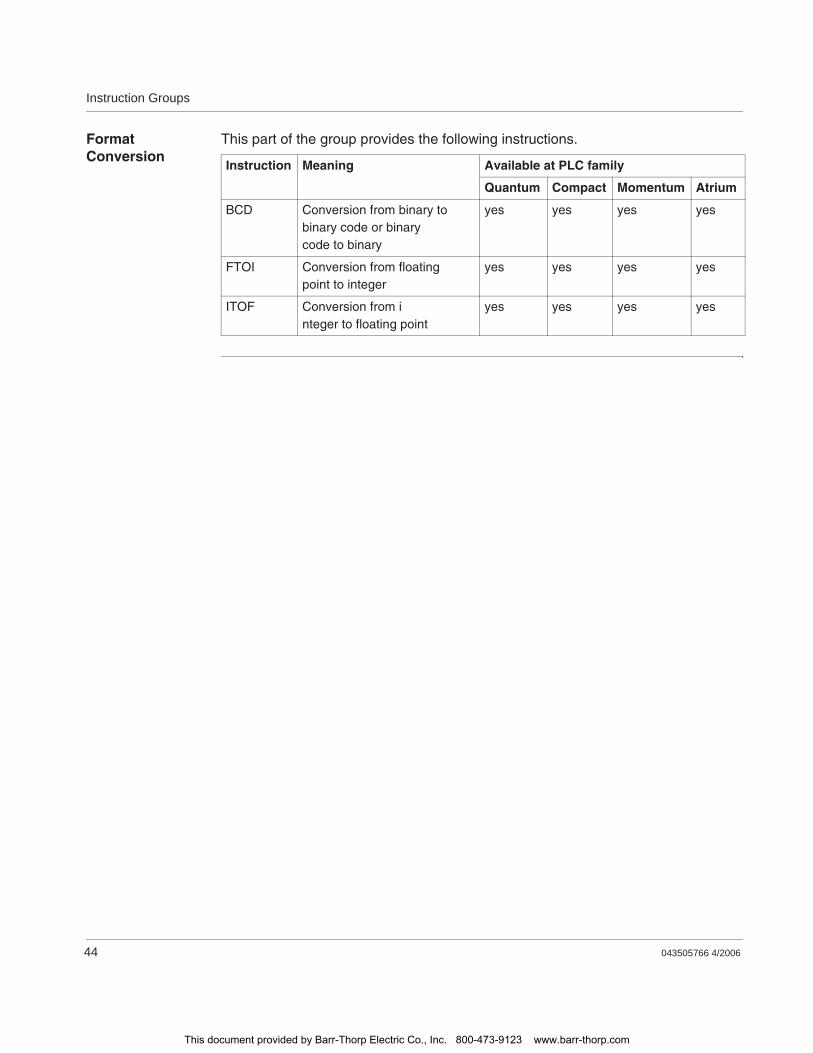
Instruction Groups
44 043505766 4/2006
Format Conversion
This part of the group provides the following instructions.
Instruction Meaning Available at PLC family
Quantum Compact Momentum Atrium
BCD Conversion from binary to binary code or binary code to binary
yes yes yes yes
FTOI Conversion from floating point to integer
yes yes yes yes
ITOF Conversion from integer to floating point
yes yes yes yes
This document provided by Barr-Thorp Electric Co., Inc. 800-473-9123 www.barr-thorp.com
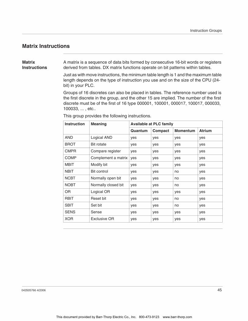
Instruction Groups
043505766 4/2006 45
Matrix Instructions
Matrix Instructions
A matrix is a sequence of data bits formed by consecutive 16-bit words or registers derived from tables. DX matrix functions operate on bit patterns within tables.
Just as with move instructions, the minimum table length is 1 and the maximum table length depends on the type of instruction you use and on the size of the CPU (24-bit) in your PLC.
Groups of 16 discretes can also be placed in tables. The reference number used is the first discrete in the group, and the other 15 are implied. The number of the first discrete must be of the first of 16 type 000001, 100001, 000017, 100017, 000033, 100033, ... , etc..
This group provides the following instructions.
Instruction Meaning Available at PLC family
Quantum Compact Momentum Atrium
AND Logical AND yes yes yes yes
BROT Bit rotate yes yes yes yes
CMPR Compare register yes yes yes yes
COMP Complement a matrix yes yes yes yes
MBIT Modify bit yes yes yes yes
NBIT Bit control yes yes no yes
NCBT Normally open bit yes yes no yes
NOBT Normally closed bit yes yes no yes
OR Logical OR yes yes yes yes
RBIT Reset bit yes yes no yes
SBIT Set bit yes yes no yes
SENS Sense yes yes yes yes
XOR Exclusive OR yes yes yes yes
This document provided by Barr-Thorp Electric Co., Inc. 800-473-9123 www.barr-thorp.com
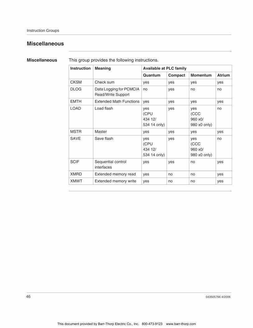
Instruction Groups
46 043505766 4/2006
Miscellaneous
Miscellaneous This group provides the following instructions.
Instruction Meaning Available at PLC family
Quantum Compact Momentum Atrium
CKSM Check sum yes yes yes yes
DLOG Data Logging for PCMCIA Read/Write Support
no yes no no
EMTH Extended Math Functions yes yes yes yes
LOAD Load flash yes(CPU 434 12/534 14 only)
yes yes(CCC 960 x0/980 x0 only)
no
MSTR Master yes yes yes yes
SAVE Save flash yes(CPU 434 12/534 14 only)
yes yes(CCC 960 x0/980 x0 only)
no
SCIF Sequential control interfaces
yes yes no yes
XMRD Extended memory read yes no no yes
XMWT Extended memory write yes no no yes
This document provided by Barr-Thorp Electric Co., Inc. 800-473-9123 www.barr-thorp.com
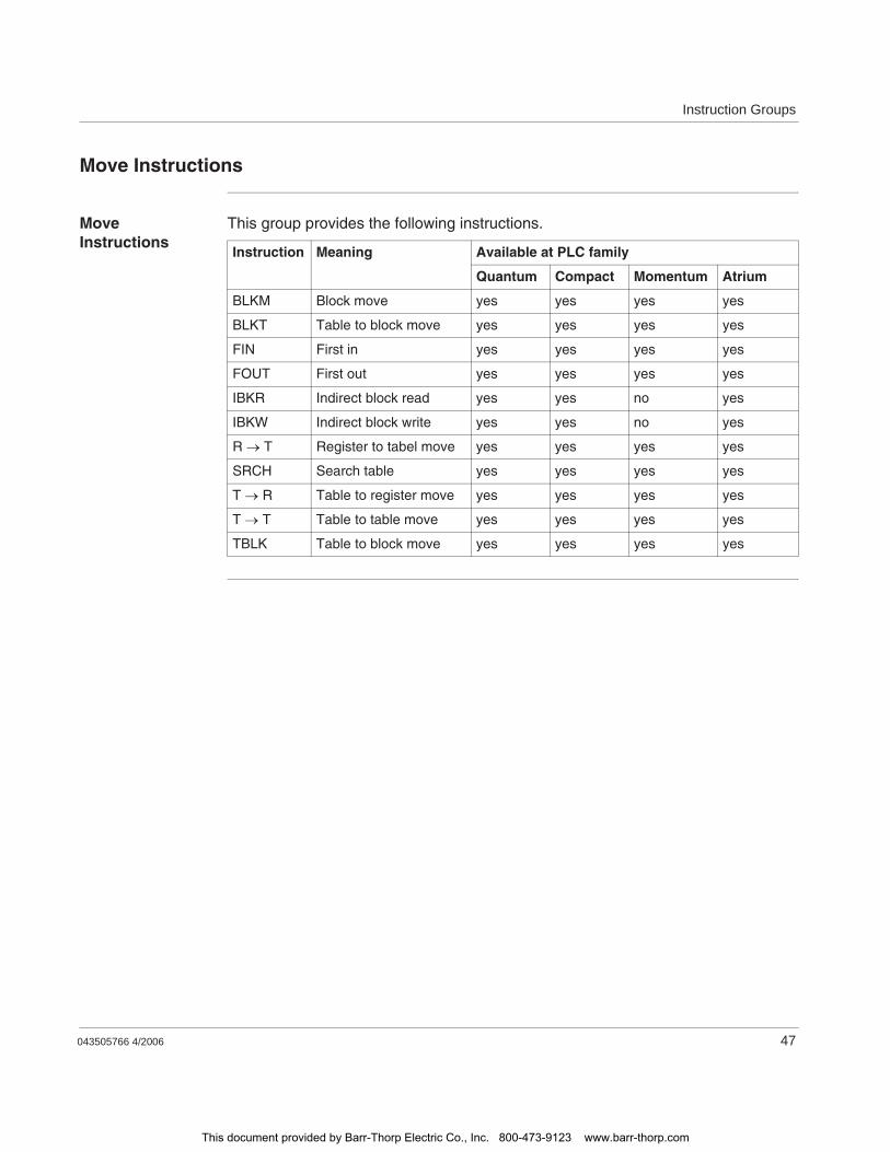
Instruction Groups
043505766 4/2006 47
Move Instructions
Move Instructions
This group provides the following instructions.
Instruction Meaning Available at PLC family
Quantum Compact Momentum Atrium
BLKM Block move yes yes yes yes
BLKT Table to block move yes yes yes yes
FIN First in yes yes yes yes
FOUT First out yes yes yes yes
IBKR Indirect block read yes yes no yes
IBKW Indirect block write yes yes no yes
R T Register to tabel move yes yes yes yes
SRCH Search table yes yes yes yes
T R Table to register move yes yes yes yes
T T Table to table move yes yes yes yes
TBLK Table to block move yes yes yes yes
This document provided by Barr-Thorp Electric Co., Inc. 800-473-9123 www.barr-thorp.com
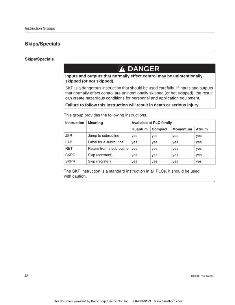
Instruction Groups
48 043505766 4/2006
Skips/Specials
Skips/Specials
This group provides the following instructions.
The SKP instruction is a standard instruction in all PLCs. It should be used with caution.
Inputs and outputs that normally effect control may be unintentionally skipped (or not skipped).SKP is a dangerous instruction that should be used carefully. If inputs and outputs that normally effect control are unintentionally skipped (or not skipped), the result can create hazardous conditions for personnel and application equipment.
Failure to follow this instruction will result in death or serious injury.
Instruction Meaning Available at PLC family
Quantum Compact Momentum Atrium
JSR Jump to subroutine yes yes yes yes
LAB Label for a subroutine yes yes yes yes
RET Return from a subroutine yes yes yes yes
SKPC Skip (constant) yes yes yes yes
SKPR Skip (register) yes yes yes yes
DANGER
This document provided by Barr-Thorp Electric Co., Inc. 800-473-9123 www.barr-thorp.com
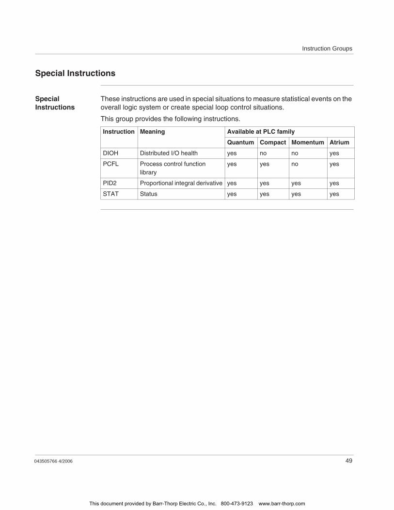
Instruction Groups
043505766 4/2006 49
Special Instructions
Special Instructions
These instructions are used in special situations to measure statistical events on the overall logic system or create special loop control situations.
This group provides the following instructions.
Instruction Meaning Available at PLC family
Quantum Compact Momentum Atrium
DIOH Distributed I/O health yes no no yes
PCFL Process control function library
yes yes no yes
PID2 Proportional integral derivative yes yes yes yes
STAT Status yes yes yes yes
This document provided by Barr-Thorp Electric Co., Inc. 800-473-9123 www.barr-thorp.com
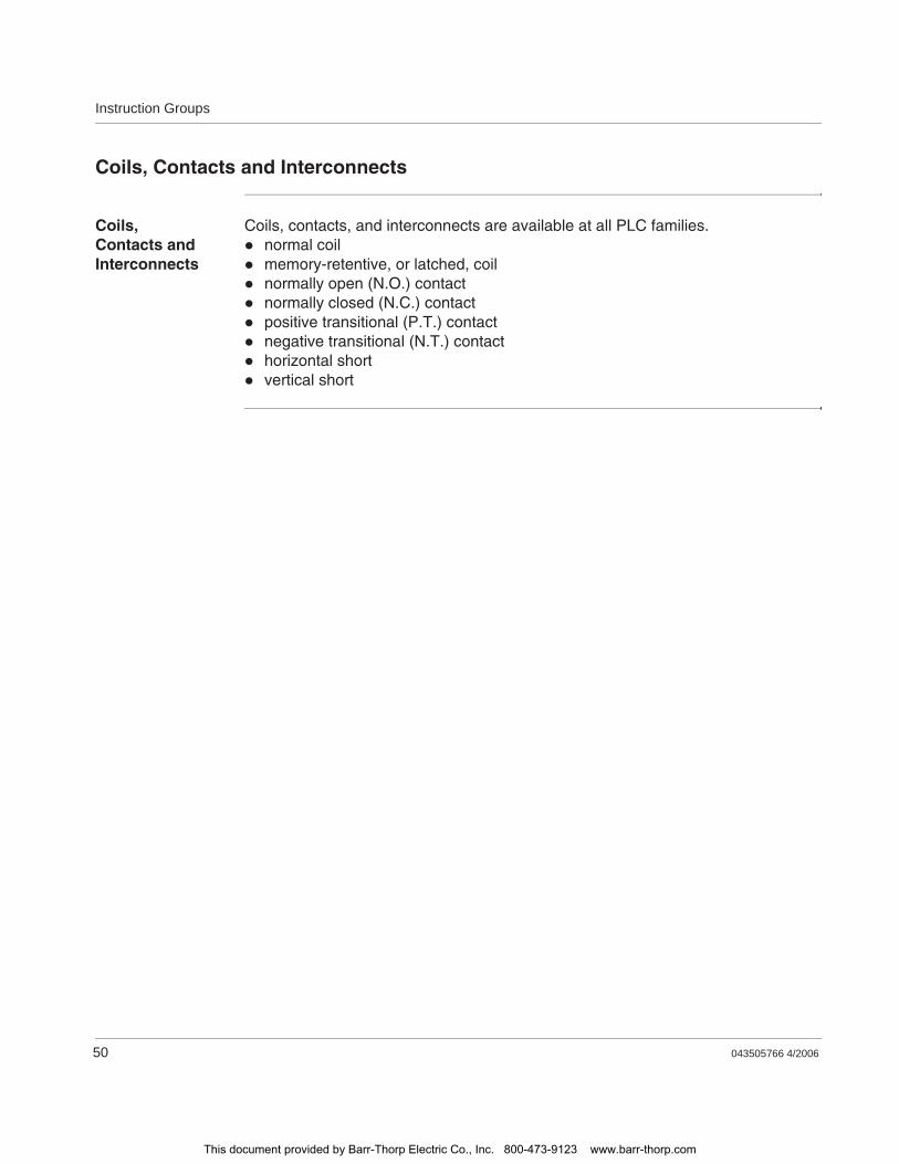
Instruction Groups
50 043505766 4/2006
Coils, Contacts and Interconnects
Coils, Contacts and Interconnects
Coils, contacts, and interconnects are available at all PLC families.normal coilmemory-retentive, or latched, coilnormally open (N.O.) contactnormally closed (N.C.) contactpositive transitional (P.T.) contactnegative transitional (N.T.) contacthorizontal shortvertical short
This document provided by Barr-Thorp Electric Co., Inc. 800-473-9123 www.barr-thorp.com

043505766 4/2006 51
6Equation Networks
At a Glance
Overview Equation network is a departure from standard ladder logic. Instead of using a two- or three-high function block configuration, this instruction takes a ladder logic network and uses it as an editor where you can compose a complex equation using algebraic notation. It allows you to use standard math operators such as +, -, *, /, as well as conditional and logical expressions. It also lets you specify variables and constants as necessary and group expressions in nested layers of parentheses.
The power of an equation network is its ability to deal with complexity in a clear and efficient way. An equation composed in a single equation network might require many networks of standard ladder logic to produce the same result. An equation network can also be read and understood by other users without the need for detailed annotation, as is often required when standard ladder logic is used for complex calculations.
What's in this Chapter?
This chapter contains the following topics:
Topic Page
Equation Network Structure 52
Mathematical Equations in Equation Networks 55
Mathematical Operations in Equation Networks 59
Mathematical Functions in Equation Networks 64
Data Conversions in an Equation Network 66
Roundoff Differences in PLCs without a Math Coprocessor 68
Benchmark Performance 69
This document provided by Barr-Thorp Electric Co., Inc. 800-473-9123 www.barr-thorp.com
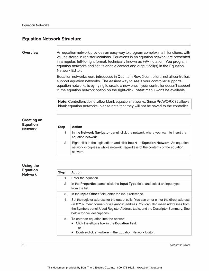
Equation Networks
52 043505766 4/2006
Equation Network Structure
Overview An equation network provides an easy way to program complex math functions, with values stored in register locations. Equations in an equation network are presented in a regular, left-to-right format, technically known as infix notation. You program equation networks and set its enable contact and output coil(s) in the Equation Network Editor.
Equation networks were introduced in Quantum Rev. 2 controllers; not all controllers support equation networks. The easiest way to see if your controller supports equation networks is by trying to create a new one; if your controller doesn’t support it, the equation network option on the right-click Insert menu won’t be available.
Creating an Equation Network
Using the Equation Network
Note: Controllers do not allow blank equation networks. Since ProWORX 32 allows blank equation networks, please note that they will not be saved to the controller.
Step Action
1 In the Network Navigator panel, click the network where you want to insert the equation network.
2 Right-click in the logic editor, and click Insert Equation Network. An equation network occupies a whole network, regardless of the contents of the equation network.
Step Action
1 Enter the equation.
2 In the Properties panel, click the Input Type field, and select an input type from the list.
3 In the Input Offset field, enter the input reference.
4 Set the register address for the output coils. You can enter either the direct address (in X:Y numeric format) or a symbolic address. You can also insert addresses from the Symbols panel, Used Register Address table, and the Descriptor Summary. See below for coil descriptions.
5 To enter an equation into the network:Click the ellipsis box in the Equation field.- or -Double-click anywhere in the Equation Network Editor.
This document provided by Barr-Thorp Electric Co., Inc. 800-473-9123 www.barr-thorp.com
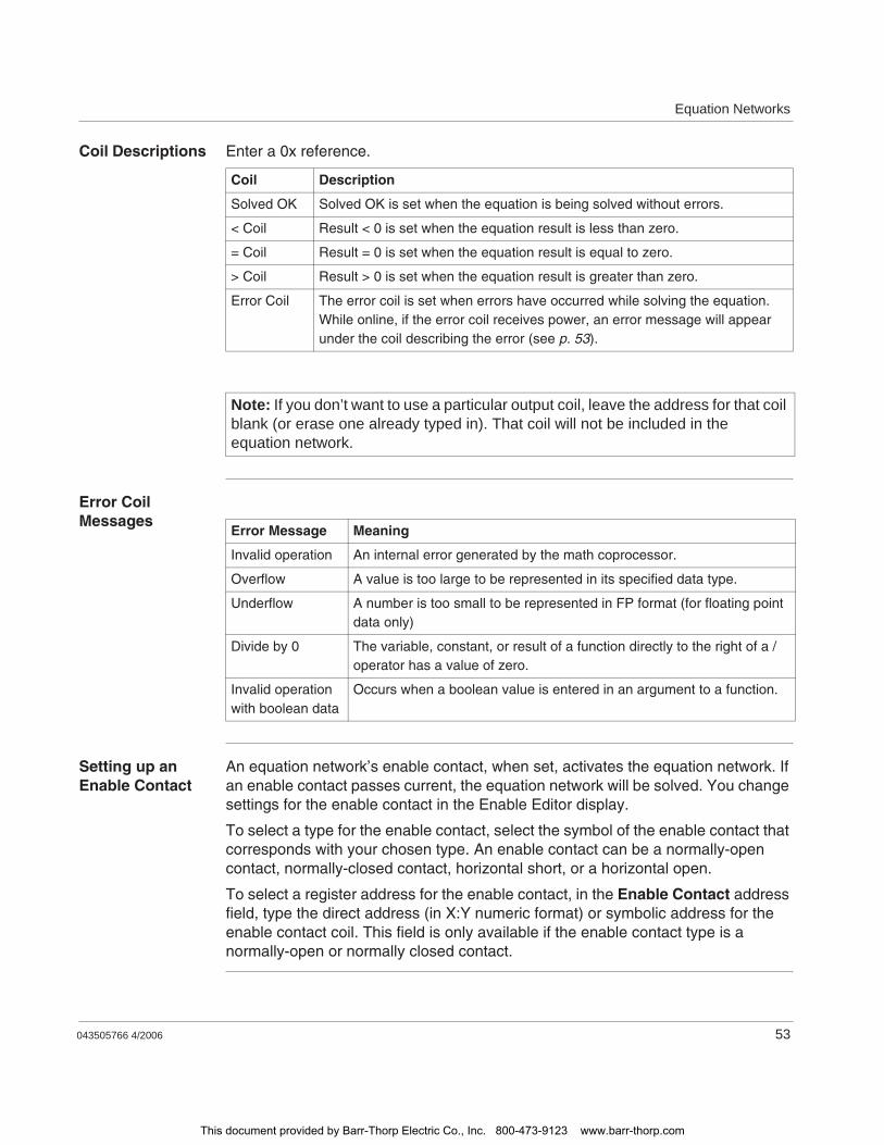
Equation Networks
043505766 4/2006 53
Coil Descriptions Enter a 0x reference.
Error Coil Messages
Setting up an Enable Contact
An equation network’s enable contact, when set, activates the equation network. If an enable contact passes current, the equation network will be solved. You change settings for the enable contact in the Enable Editor display.
To select a type for the enable contact, select the symbol of the enable contact that corresponds with your chosen type. An enable contact can be a normally-open contact, normally-closed contact, horizontal short, or a horizontal open.
To select a register address for the enable contact, in the Enable Contact address field, type the direct address (in X:Y numeric format) or symbolic address for the enable contact coil. This field is only available if the enable contact type is a normally-open or normally closed contact.
Coil Description
Solved OK Solved OK is set when the equation is being solved without errors.
< Coil Result < 0 is set when the equation result is less than zero.
= Coil Result = 0 is set when the equation result is equal to zero.
> Coil Result > 0 is set when the equation result is greater than zero.
Error Coil The error coil is set when errors have occurred while solving the equation. While online, if the error coil receives power, an error message will appear under the coil describing the error (see p. 53).
Note: If you don’t want to use a particular output coil, leave the address for that coil blank (or erase one already typed in). That coil will not be included in the equation network.
Error Message Meaning
Invalid operation An internal error generated by the math coprocessor.
Overflow A value is too large to be represented in its specified data type.
Underflow A number is too small to be represented in FP format (for floating point data only)
Divide by 0 The variable, constant, or result of a function directly to the right of a / operator has a value of zero.
Invalid operation with boolean data
Occurs when a boolean value is entered in an argument to a function.
This document provided by Barr-Thorp Electric Co., Inc. 800-473-9123 www.barr-thorp.com
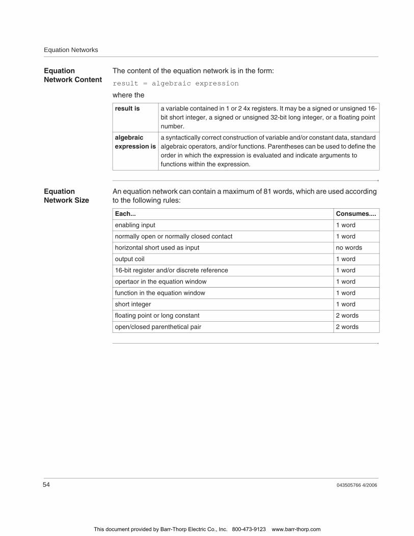
Equation Networks
54 043505766 4/2006
Equation Network Content
The content of the equation network is in the form:
result = algebraic expression
where the
Equation Network Size
An equation network can contain a maximum of 81 words, which are used according to the following rules:
result is a variable contained in 1 or 2 4x registers. It may be a signed or unsigned 16-bit short integer, a signed or unsigned 32-bit long integer, or a floating point number.
algebraic expression is
a syntactically correct construction of variable and/or constant data, standard algebraic operators, and/or functions. Parentheses can be used to define the order in which the expression is evaluated and indicate arguments to functions within the expression.
Each... Consumes....
enabling input 1 word
normally open or normally closed contact 1 word
horizontal short used as input no words
output coil 1 word
16-bit register and/or discrete reference 1 word
opertaor in the equation window 1 word
function in the equation window 1 word
short integer 1 word
floating point or long constant 2 words
open/closed parenthetical pair 2 words
This document provided by Barr-Thorp Electric Co., Inc. 800-473-9123 www.barr-thorp.com
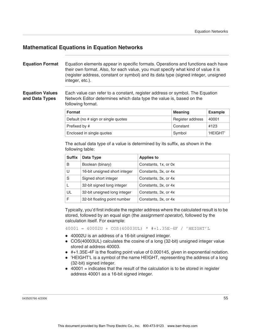
Equation Networks
043505766 4/2006 55
Mathematical Equations in Equation Networks
Equation Format Equation elements appear in specific formats. Operations and functions each have their own format. Also, for each value, you must specify what kind of value it is (register address, constant or symbol) and its data type (signed integer, unsigned integer, etc.).
Equation Values and Data Types
Each value can refer to a constant, register address or symbol. The Equation Network Editor determines which data type the value is, based on the following format.
The actual data type of a value is determined by its suffix, as shown in the following table:
Typically, you’d first indicate the register address where the calculated result is to be stored, followed by an equal sign (the assignment operator), followed by the calculation itself. For example:
40001 = 40002U + COS(40003UL) * #+1.35E-4F / ’HEIGHT’L
40002U is an address of a 16-bit unsigned integer.COS(40003UL) calculates the cosine of a long (32-bit) unsigned integer value stored at address 40003.#+1.35E-4F is the floating point value of 0.000145, given in exponential notation.’HEIGHT’L is a symbol of the name HEIGHT, representing the address of a long (32-bit) signed integer.40001 = indicates that the result of the calculation is to be stored in register address 40001 as a 16-bit signed integer.
Format Meaning Example
Default (no # sign or single quotes Register address 40001
Prefixed by # Constant #123
Enclosed in single quotes Symbol ‘HEIGHT’
Suffix Data Type Applies to
B Boolean (binary) Constants, 1x, or 0x
U 16-bit unsigned short integer Constants, 3x, or 4x
S Signed short integer Constants, 3x, or 4x
L 32-bit signed long integer Constants, 3x, or 4x
UL 32-bit unsigned long integer Constants, 3x, or 4x
F 32-bit floating point number Constants, 3x, or 4x
This document provided by Barr-Thorp Electric Co., Inc. 800-473-9123 www.barr-thorp.com
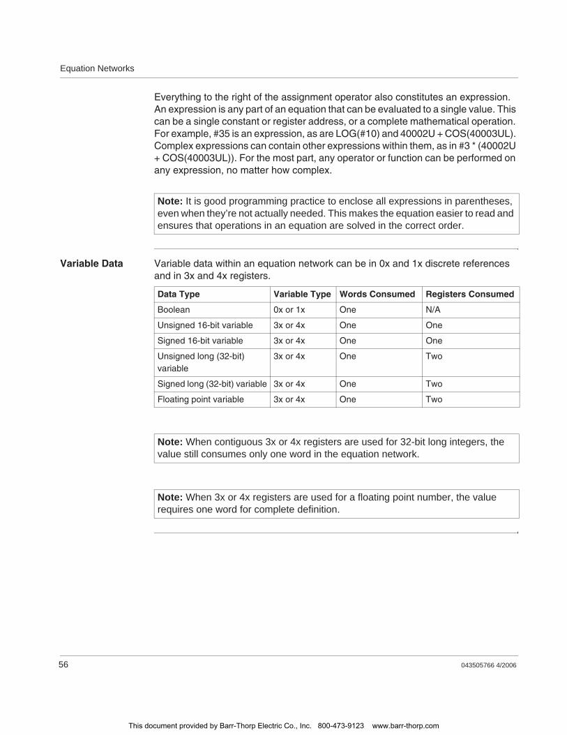
Equation Networks
56 043505766 4/2006
Everything to the right of the assignment operator also constitutes an expression. An expression is any part of an equation that can be evaluated to a single value. This can be a single constant or register address, or a complete mathematical operation. For example, #35 is an expression, as are LOG(#10) and 40002U + COS(40003UL). Complex expressions can contain other expressions within them, as in #3 * (40002U + COS(40003UL)). For the most part, any operator or function can be performed on any expression, no matter how complex.
Variable Data Variable data within an equation network can be in 0x and 1x discrete references and in 3x and 4x registers.
Note: It is good programming practice to enclose all expressions in parentheses, even when they’re not actually needed. This makes the equation easier to read and ensures that operations in an equation are solved in the correct order.
Data Type Variable Type Words Consumed Registers Consumed
Boolean 0x or 1x One N/A
Unsigned 16-bit variable 3x or 4x One One
Signed 16-bit variable 3x or 4x One One
Unsigned long (32-bit) variable
3x or 4x One Two
Signed long (32-bit) variable 3x or 4x One Two
Floating point variable 3x or 4x One Two
Note: When contiguous 3x or 4x registers are used for 32-bit long integers, the value still consumes only one word in the equation network.
Note: When 3x or 4x registers are used for a floating point number, the value requires one word for complete definition.
This document provided by Barr-Thorp Electric Co., Inc. 800-473-9123 www.barr-thorp.com
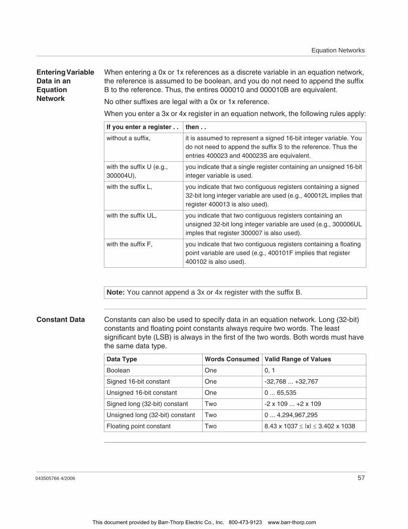
Equation Networks
043505766 4/2006 57
Entering Variable Data in an Equation Network
When entering a 0x or 1x references as a discrete variable in an equation network, the reference is assumed to be boolean, and you do not need to append the suffix B to the reference. Thus, the entires 000010 and 000010B are equivalent.
No other suffixes are legal with a 0x or 1x reference.
When you enter a 3x or 4x register in an equation network, the following rules apply:
Constant Data Constants can also be used to specify data in an equation network. Long (32-bit) constants and floating point constants always require two words. The least significant byte (LSB) is always in the first of the two words. Both words must have the same data type.
If you enter a register . . then . .
without a suffix, it is assumed to represent a signed 16-bit integer variable. You do not need to append the suffix S to the reference. Thus the entries 400023 and 400023S are equivalent.
with the suffix U (e.g., 300004U),
you indicate that a single register containing an unsigned 16-bit integer variable is used.
with the suffix L, you indicate that two contiguous registers containing a signed 32-bit long integer variable are used (e.g., 400012L implies that register 400013 is also used).
with the suffix UL, you indicate that two contiguous registers containing an unsigned 32-bit long integer variable are used (e.g., 300006UL imples that register 300007 is also used).
with the suffix F, you indicate that two contiguous registers containing a floating point variable are used (e.g., 400101F implies that register 400102 is also used).
Note: You cannot append a 3x or 4x register with the suffix B.
Data Type Words Consumed Valid Range of Values
Boolean One 0, 1
Signed 16-bit constant One -32,768 ... +32,767
Unsigned 16-bit constant One 0 ... 65,535
Signed long (32-bit) constant Two -2 x 10⁹ ... +2 x 10⁹
Unsigned long (32-bit) constant Two 0 ... 4,294,967,295
Floating point constant Two 8.43 x 1037 |x| 3.402 x 1038
This document provided by Barr-Thorp Electric Co., Inc. 800-473-9123 www.barr-thorp.com
Equation Networks
58 043505766 4/2006
Entering Constant Data in an Equation Network
A constant is prefaced with a # sign and appended with a data type suffix (See p. 55). All constant values are in decimal format. Hexadecimal values are not allowed in ProWORX.
If you enter a constant in an equation network without a suffix, it is assumed to a signed short integer. For example, the entries #-3574 and #-3574S are equivalent.
A boolean constant must have the suffix B. The only two valid boolean constants are #0B and #1B. No other values are legal boolean constants.
Exponential Notation
Floating point numbers are normally specified in exponential notation, as in:
+1.34E-4
This represents 1.35 times 10 to the -4th power, or 1.35 times 0.0001. Thus, we would shift the decimal place four places to the left to get 0.000135. The -4 part is called the exponent (note the preceding E) and can be a positive or negative number.
In the Equation Network Editor, you must also indicate:
That these numbers are constants; andTheir data types. For example, integers or floating point numbers.
The default data type is unsigned 16-bit integer. So, since the above value is a fraction (and therefore must be a floating point number), it would have to appear as #+1.35E-4F.
With no data type suffix, numbers in exponential notation are assumed to be integers. For example, #+1.35E+2 represents the unsigned 16-bit integer value 135. Exponential notation is particularly useful for very large integers.
This document provided by Barr-Thorp Electric Co., Inc. 800-473-9123 www.barr-thorp.com

Equation Networks
043505766 4/2006 59
Mathematical Operations in Equation Networks
Mathematical Operations
The following table lists the mathematical operations you can include in your equation:
Type Operator Result
Assignment operatorThe assignment operator = is used to assign a storage place for the results of the equation. All equations will use the assignment operator. The format is:ADDRESS = EXPRESSIONWhere ADDRESS is a valid register address and EXPRESSION is a valid value or expression assigned to the address.
= Assignment
Unary operatorUnary means single, so unary operators are used on only one value. The unary operator is placed just before the value or expression to which it is applied. For example, -(30002) returns -1 times the number stored at address 30002.
- Negation. The result is -1 times the value.
~ Ones complement. This works on the binary representation of a value: all 1s are changed to 0s and vice versa.
Exponentiation operatorTakes values to a specified power. 40001**3 returns the (integer) value stored at 40001, taken to the third power.
** Exponentiation
Arithmetic operatorThese require two values, one before and one after the operator. These values can be any valid expression. For example, #4 * 40003 results in four multiplied by the value stored at address 40003.
* Multiplication
/ Division
+ Addition
- Subtraction
This document provided by Barr-Thorp Electric Co., Inc. 800-473-9123 www.barr-thorp.com
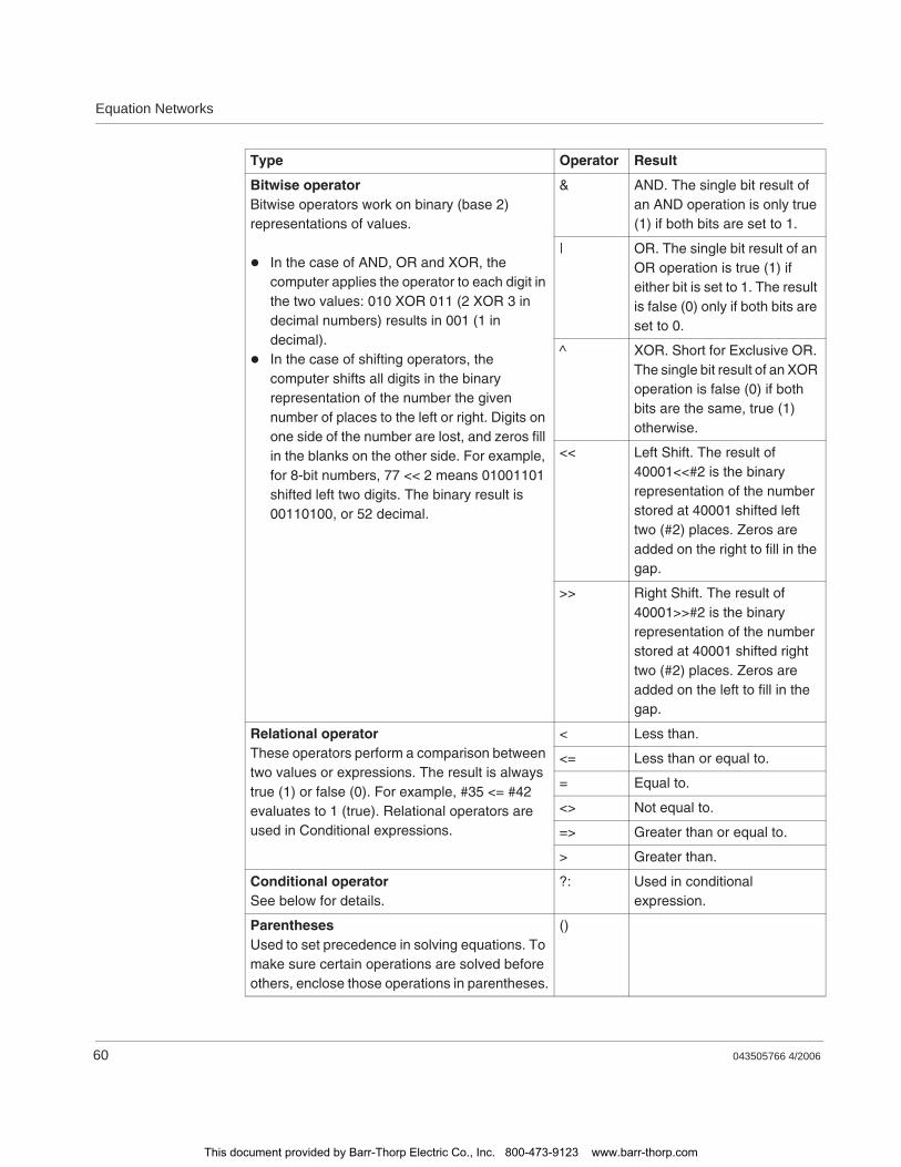
Equation Networks
60 043505766 4/2006
Bitwise operatorBitwise operators work on binary (base 2) representations of values.
In the case of AND, OR and XOR, the computer applies the operator to each digit in the two values: 010 XOR 011 (2 XOR 3 in decimal numbers) results in 001 (1 in decimal).In the case of shifting operators, the computer shifts all digits in the binary representation of the number the given number of places to the left or right. Digits on one side of the number are lost, and zeros fill in the blanks on the other side. For example, for 8-bit numbers, 77 << 2 means 01001101 shifted left two digits. The binary result is 00110100, or 52 decimal.
& AND. The single bit result of an AND operation is only true (1) if both bits are set to 1.
| OR. The single bit result of an OR operation is true (1) if either bit is set to 1. The result is false (0) only if both bits are set to 0.
^ XOR. Short for Exclusive OR. The single bit result of an XOR operation is false (0) if both bits are the same, true (1) otherwise.
<< Left Shift. The result of 40001<<#2 is the binary representation of the number stored at 40001 shifted left two (#2) places. Zeros are added on the right to fill in the gap.
>> Right Shift. The result of 40001>>#2 is the binary representation of the number stored at 40001 shifted right two (#2) places. Zeros are added on the left to fill in the gap.
Relational operatorThese operators perform a comparison between two values or expressions. The result is always true (1) or false (0). For example, #35 <= #42 evaluates to 1 (true). Relational operators are used in Conditional expressions.
< Less than.
<= Less than or equal to.
= Equal to.
<> Not equal to.
=> Greater than or equal to.
> Greater than.
Conditional operatorSee below for details.
?: Used in conditional expression.
ParenthesesUsed to set precedence in solving equations. To make sure certain operations are solved before others, enclose those operations in parentheses.
()
Type Operator Result
This document provided by Barr-Thorp Electric Co., Inc. 800-473-9123 www.barr-thorp.com
Equation Networks
043505766 4/2006 61
How an Equation Network Resolves an Equation
An equation network calculates its result in one of two ways, depending on the operator types used in the expression.
Single Expression
Evaluate a single expression and execute it by copying the derived value to the result register.
Conditional Expression
Evaluate the validity of the first of three arguments in a conditional expression and execute it by copying the value from either the second or third argument in the conditional expression to the result register.
If the expression being evaluated contains only some combination of unary, exponentiation, mathematical, and/or logical bitwise operators, it is treated as a single argument and is solved via single expression. For example, in the equation
400001 = (#16 ** #2 - #5) * #7
the square of 16 (256( minus 5 (251) is multiplied by 7, and the result (1,757) is copied to register 400001.
If you use one or more of the six relational operators shown in the previous table, you create the first of three arguments that comprise a conditional expression. The conditional operators must be used to create then/else arguments in the expression, and conditional expression is used to execute the result. For example, in the equation
400001 = 400002 >= #100 ? 300001 : 300002
the value in register 400002 is evaluated to see if it is greater than or equal to 100. This is the first argument in the conditional expression. If the value is greater than or equal to 100, the second argument is executed and the value in register 300001 is copied to register 400001. It is less than 100, the third argument is executed and the value in register 300002 is copied to register 400001
This document provided by Barr-Thorp Electric Co., Inc. 800-473-9123 www.barr-thorp.com
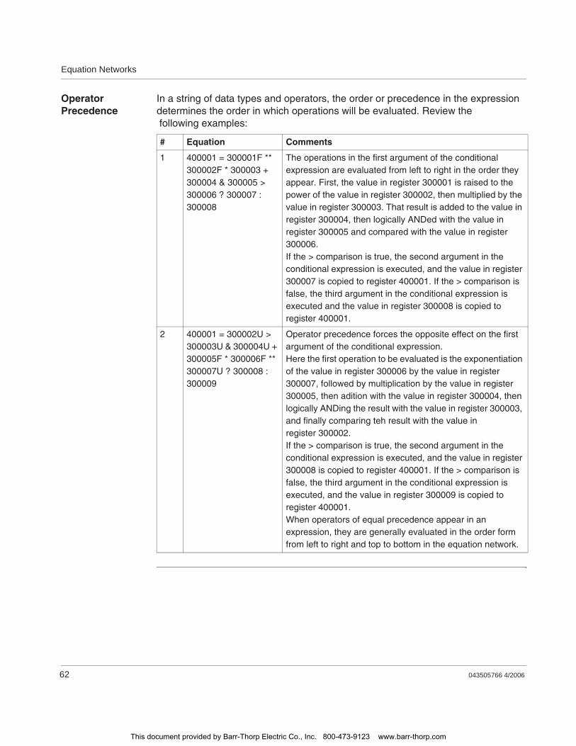
Equation Networks
62 043505766 4/2006
Operator Precedence
In a string of data types and operators, the order or precedence in the expression determines the order in which operations will be evaluated. Review the following examples:
# Equation Comments
1 400001 = 300001F ** 300002F * 300003 + 300004 & 300005 > 300006 ? 300007 : 300008
The operations in the first argument of the conditional expression are evaluated from left to right in the order they appear. First, the value in register 300001 is raised to the power of the value in register 300002, then multiplied by the value in register 300003. That result is added to the value in register 300004, then logically ANDed with the value in register 300005 and compared with the value in register 300006.If the > comparison is true, the second argument in the conditional expression is executed, and the value in register 300007 is copied to register 400001. If the > comparison is false, the third argument in the conditional expression is executed and the value in register 300008 is copied to register 400001.
2 400001 = 300002U > 300003U & 300004U + 300005F * 300006F ** 300007U ? 300008 : 300009
Operator precedence forces the opposite effect on the first argument of the conditional expression.Here the first operation to be evaluated is the exponentiation of the value in register 300006 by the value in register 300007, followed by multiplication by the value in register 300005, then adition with the value in register 300004, then logically ANDing the result with the value in register 300003, and finally comparing teh result with the value in register 300002.If the > comparison is true, the second argument in the conditional expression is executed, and the value in register 300008 is copied to register 400001. If the > comparison is false, the third argument in the conditional expression is executed, and the value in register 300009 is copied to register 400001.When operators of equal precedence appear in an expression, they are generally evaluated in the order form from left to right and top to bottom in the equation network.
This document provided by Barr-Thorp Electric Co., Inc. 800-473-9123 www.barr-thorp.com
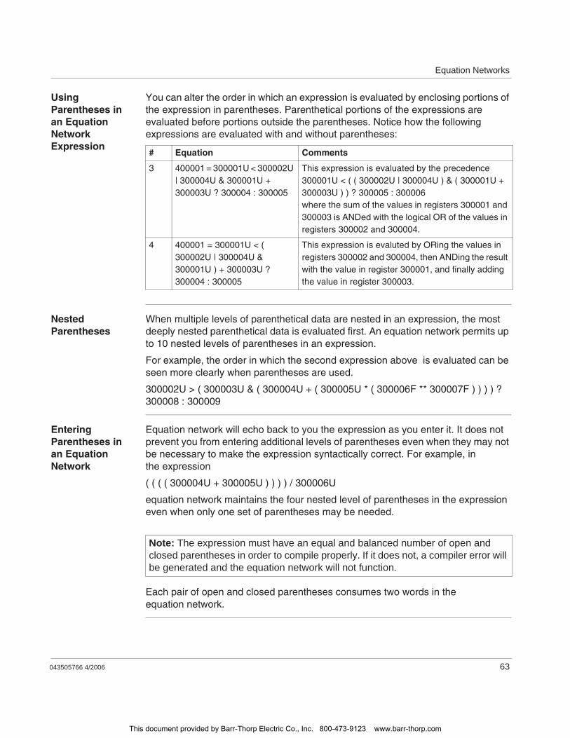
Equation Networks
043505766 4/2006 63
Using Parentheses in an Equation Network Expression
You can alter the order in which an expression is evaluated by enclosing portions of the expression in parentheses. Parenthetical portions of the expressions are evaluated before portions outside the parentheses. Notice how the following expressions are evaluated with and without parentheses:
Nested Parentheses
When multiple levels of parenthetical data are nested in an expression, the most deeply nested parenthetical data is evaluated first. An equation network permits up to 10 nested levels of parentheses in an expression.
For example, the order in which the second expression above is evaluated can be seen more clearly when parentheses are used.
300002U > ( 300003U & ( 300004U + ( 300005U * ( 300006F ** 300007F ) ) ) ) ? 300008 : 300009
Entering Parentheses in an Equation Network
Equation network will echo back to you the expression as you enter it. It does not prevent you from entering additional levels of parentheses even when they may not be necessary to make the expression syntactically correct. For example, in the expression
( ( ( ( 300004U + 300005U ) ) ) ) / 300006U
equation network maintains the four nested level of parentheses in the expression even when only one set of parentheses may be needed.
Each pair of open and closed parentheses consumes two words in the equation network.
# Equation Comments
3 400001 = 300001U < 300002U | 300004U & 300001U + 300003U ? 300004 : 300005
This expression is evaluated by the precedence300001U < ( ( 300002U | 300004U ) & ( 300001U + 300003U ) ) ? 300005 : 300006where the sum of the values in registers 300001 and 300003 is ANDed with the logical OR of the values in registers 300002 and 300004.
4 400001 = 300001U < ( 300002U | 300004U & 300001U ) + 300003U ? 300004 : 300005
This expression is evaluted by ORing the values in registers 300002 and 300004, then ANDing the result with the value in register 300001, and finally adding the value in register 300003.
Note: The expression must have an equal and balanced number of open and closed parentheses in order to compile properly. If it does not, a compiler error will be generated and the equation network will not function.
This document provided by Barr-Thorp Electric Co., Inc. 800-473-9123 www.barr-thorp.com
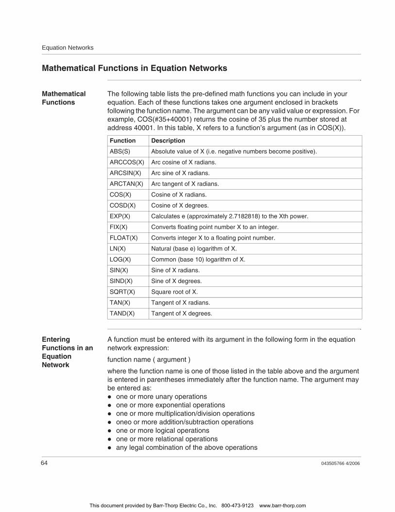
Equation Networks
64 043505766 4/2006
Mathematical Functions in Equation Networks
Mathematical Functions
The following table lists the pre-defined math functions you can include in your equation. Each of these functions takes one argument enclosed in brackets following the function name. The argument can be any valid value or expression. For example, COS(#35+40001) returns the cosine of 35 plus the number stored at address 40001. In this table, X refers to a function’s argument (as in COS(X)).
Entering Functions in an Equation Network
A function must be entered with its argument in the following form in the equation network expression:
function name ( argument )
where the function name is one of those listed in the table above and the argument is entered in parentheses immediately after the function name. The argument may be entered as:
one or more unary operationsone or more exponential operationsone or more multiplication/division operationsoneo or more addition/subtraction operationsone or more logical operationsone or more relational operationsany legal combination of the above operations
Function Description
ABS(S) Absolute value of X (i.e. negative numbers become positive).
ARCCOS(X) Arc cosine of X radians.
ARCSIN(X) Arc sine of X radians.
ARCTAN(X) Arc tangent of X radians.
COS(X) Cosine of X radians.
COSD(X) Cosine of X degrees.
EXP(X) Calculates e (approximately 2.7182818) to the Xth power.
FIX(X) Converts floating point number X to an integer.
FLOAT(X) Converts integer X to a floating point number.
LN(X) Natural (base e) logarithm of X.
LOG(X) Common (base 10) logarithm of X.
SIN(X) Sine of X radians.
SIND(X) Sine of X degrees.
SQRT(X) Square root of X.
TAN(X) Tangent of X radians.
TAND(X) Tangent of X degrees.
This document provided by Barr-Thorp Electric Co., Inc. 800-473-9123 www.barr-thorp.com
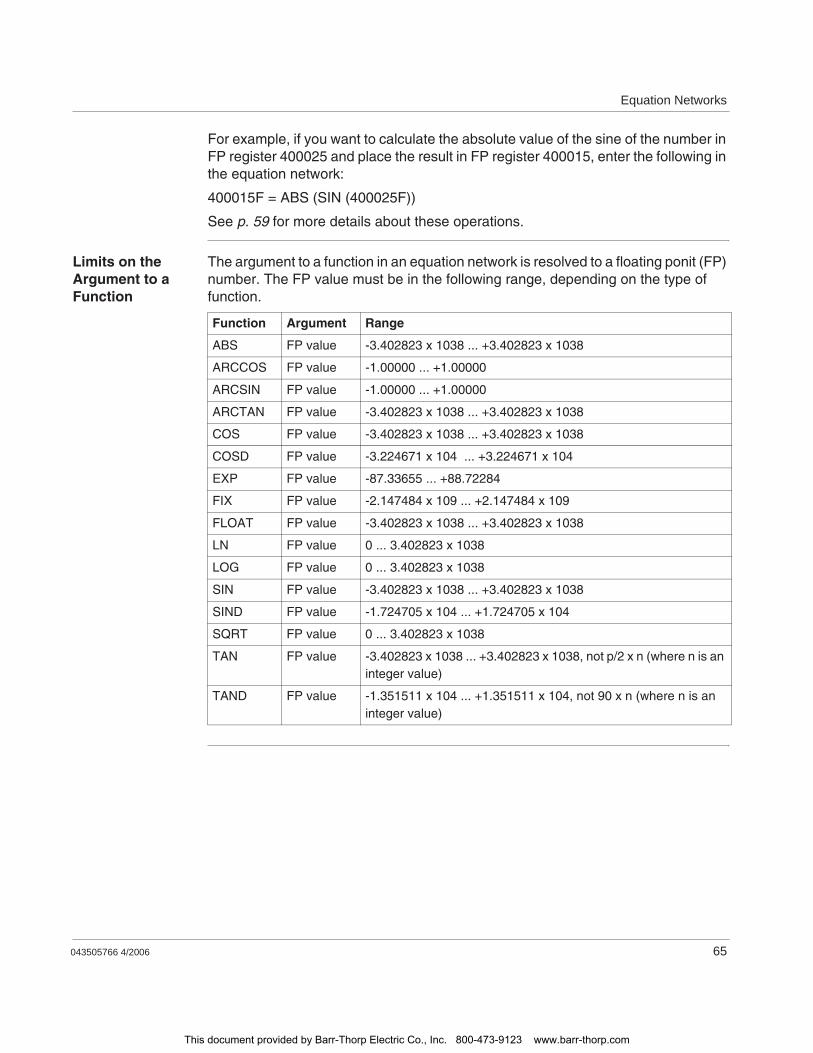
Equation Networks
043505766 4/2006 65
For example, if you want to calculate the absolute value of the sine of the number in FP register 400025 and place the result in FP register 400015, enter the following in the equation network:
400015F = ABS (SIN (400025F))
See p. 59 for more details about these operations.
Limits on the Argument to a Function
The argument to a function in an equation network is resolved to a floating ponit (FP) number. The FP value must be in the following range, depending on the type of function.
Function Argument Range
ABS FP value -3.402823 x 1038 ... +3.402823 x 1038
ARCCOS FP value -1.00000 ... +1.00000
ARCSIN FP value -1.00000 ... +1.00000
ARCTAN FP value -3.402823 x 1038 ... +3.402823 x 1038
COS FP value -3.402823 x 1038 ... +3.402823 x 1038
COSD FP value -3.224671 x 10⁴ ... +3.224671 x 10⁴
EXP FP value -87.33655 ... +88.72284
FIX FP value -2.147484 x 10⁹ ... +2.147484 x 10⁹
FLOAT FP value -3.402823 x 1038 ... +3.402823 x 1038
LN FP value 0 ... 3.402823 x 1038
LOG FP value 0 ... 3.402823 x 1038
SIN FP value -3.402823 x 1038 ... +3.402823 x 1038
SIND FP value -1.724705 x 10⁴ ... +1.724705 x 10⁴
SQRT FP value 0 ... 3.402823 x 1038
TAN FP value -3.402823 x 1038 ... +3.402823 x 1038, not p/2 x n (where n is an integer value)
TAND FP value -1.351511 x 10⁴ ... +1.351511 x 10⁴, not 90 x n (where n is an integer value)
This document provided by Barr-Thorp Electric Co., Inc. 800-473-9123 www.barr-thorp.com
Equation Networks
66 043505766 4/2006
Data Conversions in an Equation Network
Mixed Data Types in an Equation Network
In an equation network, some combinations of operators will convert the value of an operand from 1 data type to another. The following set of rules applies to mixed data types in an equation network:
All 16-bit signed and unsigned numbers are automatically promoted to 32 bits before an operation.In an operation between signed and unsigned numbers, the unsigned number is assumed to be signed without checking for overflow.An operation involving a boolean and any other data type uses the other data type and assigns a value of 1 or 0 to the boolean.An operation between floating point numbers and signed or unsigned numbers automatically promotes the long integer to floating point and assumes assigned number without checking for overflow.An operation involving a bitwise logical AND, OR, or XOR does not check data types and automatically assumes unsigned numbers.A bitwise logical AND, OR, or XOR operation with a boolean argument results in a 0 (false) or a 0xFFFFFFFF (true).The unary NOT ONE’s complement operation does not operate on floating point numbers and treats signed numbers as if they were unsigned.In a shift forward or shift back operation, the number by which the argument is being shifted is always treated as a positive integer between 0 ... 32. If the value of the by number > 32, it is automatically ANDed with 0x1f to make it < 32.Signed numbers are shifted arithmetically, and unsigned numbers are shifted logically.A floating point number that is shifted becomes useless, since its data type remains unchanged.Attempting to shift a boolean argument produces an error.The unary negation of an unsigned number produces that number’s 2’s complement.The unary negation of a signed or floating point number changes the sign of the number.The unary negation of a boolean operator results in a change of true/false state of the boolean.An absolute value operation does not change the data type of the result.Attempting to find the absolute value of a boolean argument produces an error.A floating point result is always produced by an EXP, LN, LOG, SQRT, SIN, COS, TAN, SIND, COSD, TAND, ARCSIN, ARCCOS, or ARCTAN function. If the original argument was not a floating point number, it will be promoted to one, assuming a signed number without checking for overflow. The exception is an original boolean argument, which will produce an error with any of these functions.A boolean + boolean operation is an OR operation.A boolean - boolean operation is an XOR operation.
This document provided by Barr-Thorp Electric Co., Inc. 800-473-9123 www.barr-thorp.com
Equation Networks
043505766 4/2006 67
Boolean * boolean, boolean / boolean, and boolean ** boolean operations are AND operations.A boolean assignment (=) to a signed or unsigned number produces a signed or unsigned 0 or 1.A boolean assignment (=) to a floating point number produces a floating point 0.0 or 1.0.A long/short signed/unsigned number assignment (=) to a short unsigned number produces a result in the range 0 ... 65,535. Overflow is set if the result is > 65,535.A long/short signed/unsigned number assignment (=) to a short signed number produces a result in the range -32,768 ... 32,767. Overflow is set if the result is > 32,767 or < -32,768.A floating point number assignment (=) to a long/short signed/unsigned number will be truncated.A floating point number assignment (=) to a short unsigned number produces a result in the range 0 ... 65,535. Overflow is set if the result is > 65,535.A floating point number assignment (=) to a short signed number produces a result in the range -32,768 ... 32,767. Overflow is set if the result is > 32,767 or < -32,768.A floating point number assignment (=) to a long unsigned number produces a result in the range 0 ... 4,294,967,295. Overflow is set if the result is > 4,294,967,295.A floating point number assignment (=) to a long signed number produces a result in the range -2,147,483,648 ... 2,147,483,647. Overflow is set if the result is >2,147,483,647 or < -2,147,483,648.
This document provided by Barr-Thorp Electric Co., Inc. 800-473-9123 www.barr-thorp.com
Equation Networks
68 043505766 4/2006
Roundoff Differences in PLCs without a Math Coprocessor
Overview Equation networks can be executed by Quantum PLCs like the 140 CPU 424 02 and 140 CPU 213 04, which have on-board math coprocessors, as well as by the 140 CPU 113 02 and 03 PLCs, which do not have math coprocessors. Quantum PLCs without math coprocessors use a 32-bit processing mechanism within the PLC itself to handle floating point calculations, and they can produce results that are less accurate than those produced by the 80-bit math coprocessor.
Differences in accuracy can be noticed starting in the sixth position to the right of the decimal point. For example, the 140 CPU 424 02 and 213 04 will calculate the equation
401010F = SIN(#45)
and produces the result 0.8509035, whereas the 140 CPU 113 02/03 will handle the same equation and produce the result 0.8509022.
For applications that require accuracy beyond the 5th decimal position, a Quantum PLC with a math coprocessor is recommended. Generally, if your application does not require this kind of accuracy, a PLC without a math coprocessor may be acceptable.
Another potential consideration is the effect of less accurate calculation on a truncated result. For example, a PLC with a math coprocessor will calculate the tangent of 225 degrees
401015F = TAND(#225)
as 1, whereas a PLC without a math coprocessor will produce the result 0.999991. If we were to assign the TAND operation to a non-floating point register, equation network will truncate the result so that
401040 = TAND(#225)
will produce a result of 1 when the math coprocessor is used but a result of 0 when the coprocessor is not used.
This document provided by Barr-Thorp Electric Co., Inc. 800-473-9123 www.barr-thorp.com
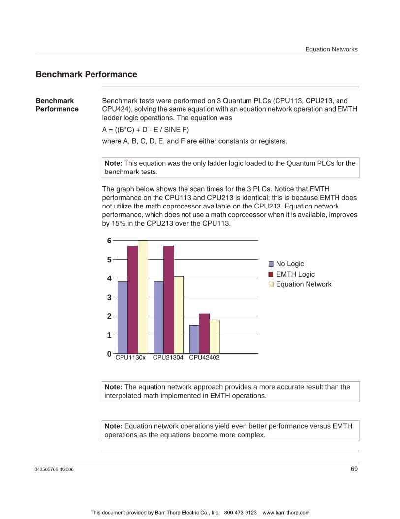
Equation Networks
043505766 4/2006 69
Benchmark Performance
Benchmark Performance
Benchmark tests were performed on 3 Quantum PLCs (CPU113, CPU213, and CPU424), solving the same equation with an equation network operation and EMTH ladder logic operations. The equation was
A = ((B*C) + D - E / SINE F)
where A, B, C, D, E, and F are either constants or registers.
The graph below shows the scan times for the 3 PLCs. Notice that EMTH performance on the CPU113 and CPU213 is identical; this is because EMTH does not utilize the math coprocessor available on the CPU213. Equation network performance, which does not use a math coprocessor when it is available, improves by 15% in the CPU213 over the CPU113.
Note: This equation was the only ladder logic loaded to the Quantum PLCs for the benchmark tests.
Note: The equation network approach provides a more accurate result than the interpolated math implemented in EMTH operations.
Note: Equation network operations yield even better performance versus EMTH operations as the equations become more complex.
0
1
2
3
4
5
6
No Logic
EMTH Logic
Equation Network
CPU1130x CPU21304 CPU42402
This document provided by Barr-Thorp Electric Co., Inc. 800-473-9123 www.barr-thorp.com

Equation Networks
70 043505766 4/2006
This document provided by Barr-Thorp Electric Co., Inc. 800-473-9123 www.barr-thorp.com
043505766 4/2006 71
7Closed Loop Control / Analog Values
At a Glance
Introduction In this chapter you will find general information about configuring closed loop control and using analog values.
What's in this Chapter?
This chapter contains the following topics:
Topic Page
Closed Loop Control / Analog Values 72
PCFL Subfunctions 73
A PID Example 77
PID2 Level Control Example 80
This document provided by Barr-Thorp Electric Co., Inc. 800-473-9123 www.barr-thorp.com
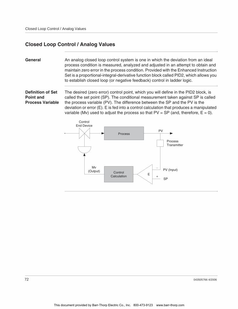
Closed Loop Control / Analog Values
72 043505766 4/2006
Closed Loop Control / Analog Values
General An analog closed loop control system is one in which the deviation from an ideal process condition is measured, analyzed and adjusted in an attempt to obtain and maintain zero error in the process condition. Provided with the Enhanced Instruction Set is a proportional-integral-derivative function block called PID2, which allows you to establish closed loop (or negative feedback) control in ladder logic.
Definition of Set Point and Process Variable
The desired (zero error) control point, which you will define in the PID2 block, is called the set point (SP). The conditional measurement taken against SP is called the process variable (PV). The difference between the SP and the PV is the deviation or error (E). E is fed into a control calculation that produces a manipulated variable (Mv) used to adjust the process so that PV = SP (and, therefore, E = 0).
ControlEnd Device
ControlCalculation
Process
Mv(Output)
ProcessTransmitter
PV
PV (Input)
SPE
+
_
This document provided by Barr-Thorp Electric Co., Inc. 800-473-9123 www.barr-thorp.com
Closed Loop Control / Analog Values
043505766 4/2006 73
PCFL Subfunctions
General The PCFL instruction gives you access to a library of process control functions utilizing analog values.
PCFL operations fall into three major categories.Advanced CalculationsSignal ProcessingRegulatory Control
Advanced Calculations
Advanced calculations are used for general mathematical purposes and are not limited to process control applications. With advanced calculations, you can create custom signal processing algorithms, derive states of the controlled process, derive statistical measures of the process, etc.
Simple math routines have already been offered in the EMTH instruction. The calculation capability included in PCFL is a textual equation calculator for writing custom equations instead of programming a series of math operations one by one.
Signal Processing
Signal processing functions are used to manipulate process and derived process signals. They can do this in a variety of ways; they linearize, filter, delay and otherwise modify a signal. This category would include functions such as an Analog Input/Output, Limiters, Lead/Lag and Ramp generators.
Regulatory Control
Regulatory functions perform closed loop control in a variety of applications. Typically, this is a PID (proportional integral derivative) negative feedback control loop. The PID functions in PCFL offer varying degrees of functionality. Function PID has the same general functionality as the PID2 instruction but uses floating point math and represents some options differently. PID is beneficial in cases where PID2 is not suitable because of numerical concerns such as round-off.
Explanation of Formula Elements
Meaning of formula elements in the following formulas:
Formula elements Meaning
Y Manipulated variable output
YP Proportional part of the calculation
YI Integral part of the calculation
YD Derivative part of the calculation
Bias Constant added to input
BT Bumpless transfer register
SP Set point
This document provided by Barr-Thorp Electric Co., Inc. 800-473-9123 www.barr-thorp.com
Closed Loop Control / Analog Values
74 043505766 4/2006
General Equations
The following general equations are valid.
Proportional Calculations
The following equations are valid.
Integral Calculation
The following equations are valid.
KP Proportional gain
Dt Time since last solve
TI Integral time constant
TD Derivative time constant
TD1 Derivative time lag
XD Error term, deviation
XD_1 Previous error term
X Process input
X_1 Previous process input
Formula elements Meaning
Equation Condition /Requirement
Integral bit ON
Integral bit OFF
High/low limits
with
Gain reduction
Gain reduction zone not used
Y YP YI YD BIAS+ + +=
Y YP YD BIAS BT+ + +=
Yhigh Y Ylow
YP YI YD f XD( )=
XD SP X GRZ 1 KGRZ––=
XD SP X–=
Equation Condition /Requirement
Proportional bit ONYP KP XD=
YP 0=
Equation Condition /Requirement
Integral bit ONYI YI KP
tTI------ XD_1 XD+
2------------------------------+=
YI 0=
This document provided by Barr-Thorp Electric Co., Inc. 800-473-9123 www.barr-thorp.com
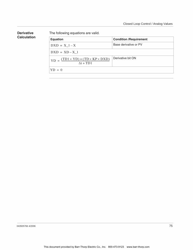
Closed Loop Control / Analog Values
043505766 4/2006 75
Derivative Calculation
The following equations are valid.
Equation Condition /Requirement
Base derivative or PV
Derivative bit ON
DXD X_1 X–=
DXD XD X_1–=
YD TD1 YD TD KP DXD+t TD1+
-------------------------------------------------------------------------------------=
YD 0=
This document provided by Barr-Thorp Electric Co., Inc. 800-473-9123 www.barr-thorp.com
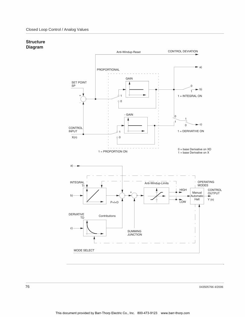
Closed Loop Control / Analog Values
76 043505766 4/2006
Structure Diagram
1
0
GAIN
b)
1
0
- GAIN
c)
a)
Y (n)b)
a)
c)
HIGH
LOW
ManualAutomatic
Halt
+
_
SET POINTSP
CONTROLINPUT
X(n)
1 = PROPORTION ON
PROPORTIONAL
Anti-Windup-Reset CONTROL DEVIATION
0
1
1 = INTEGRAL ON
0 = base Derivative on XD1 = base Derivative on X
1
0
0
1
1 = DERIVATIVE ON
INTEGRALTI
P+I+D
DERVATIVETD
Contributions
SUMMINGJUNCTION
+
Anti-Windup-Limits OPERATINGMODES
CONTROLOUTPUT
MODE SELECT
This document provided by Barr-Thorp Electric Co., Inc. 800-473-9123 www.barr-thorp.com
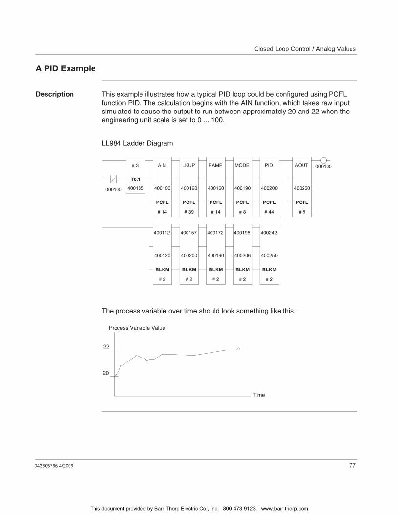
Closed Loop Control / Analog Values
043505766 4/2006 77
A PID Example
Description This example illustrates how a typical PID loop could be configured using PCFL function PID. The calculation begins with the AIN function, which takes raw input simulated to cause the output to run between approximately 20 and 22 when the engineering unit scale is set to 0 ... 100.
LL984 Ladder Diagram
The process variable over time should look something like this.
# 3
T0.1
400185
AIN
PCFL
400100
# 14
LKUP
PCFL
400120
# 39
RAMP
PCFL
400160
# 14
MODE
PCFL
400190
# 8
PID
PCFL
400200
# 44
AOUT
PCFL
400250
# 9
000100
400112
BLKM
400120
# 2
400157
BLKM
400200
# 2
400172
BLKM
400190
# 2
400196
BLKM
400206
# 2
400242
BLKM
400250
# 2
000100
Time
Process Variable Value
20
22
This document provided by Barr-Thorp Electric Co., Inc. 800-473-9123 www.barr-thorp.com
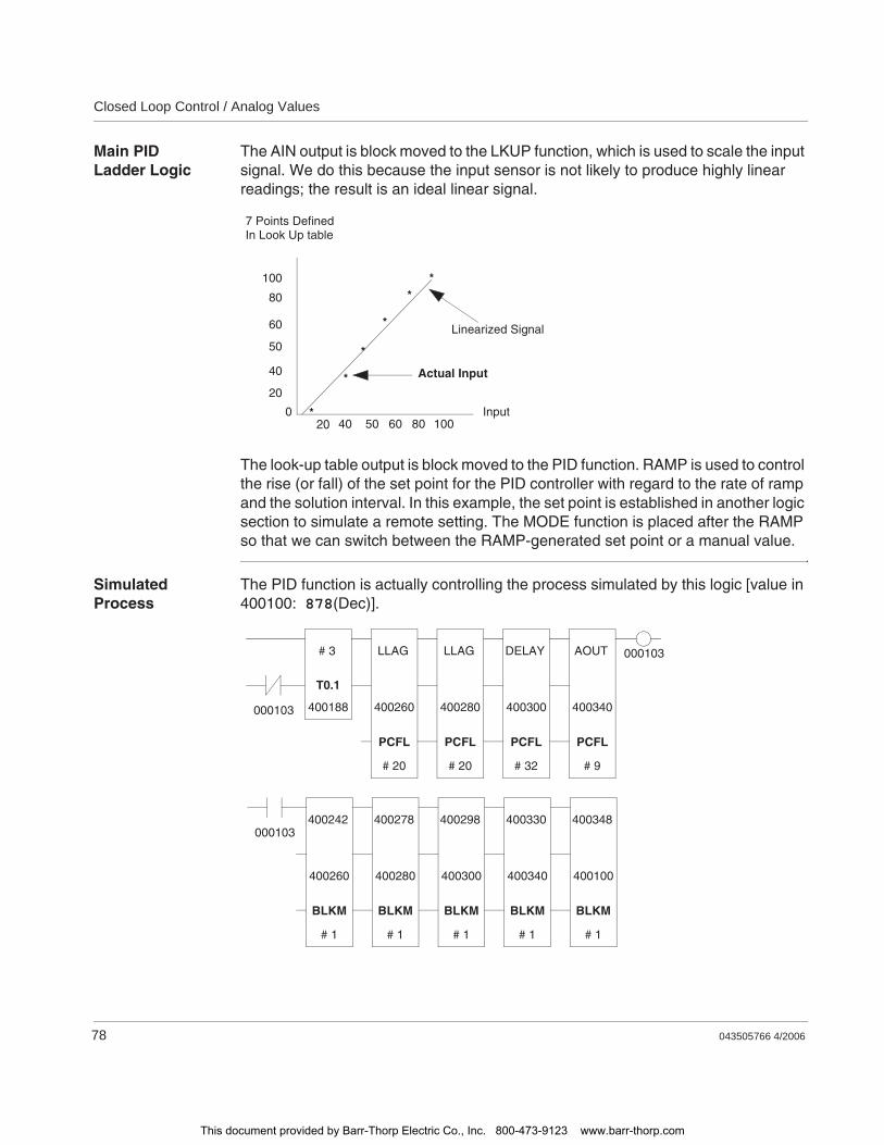
Closed Loop Control / Analog Values
78 043505766 4/2006
Main PID Ladder Logic
The AIN output is block moved to the LKUP function, which is used to scale the input signal. We do this because the input sensor is not likely to produce highly linear readings; the result is an ideal linear signal.
The look-up table output is block moved to the PID function. RAMP is used to control the rise (or fall) of the set point for the PID controller with regard to the rate of ramp and the solution interval. In this example, the set point is established in another logic section to simulate a remote setting. The MODE function is placed after the RAMP so that we can switch between the RAMP-generated set point or a manual value.
Simulated Process
The PID function is actually controlling the process simulated by this logic [value in 400100: 878(Dec)].
7 Points DefinedIn Look Up table
Input0
100
80
60
50
40
20
1008060504020
Linearized Signal
Actual Input
*
*
*
**
*
# 3
T0.1
400188
LLAG
PCFL
400260
# 20
LLAG
PCFL
400280
# 20
DELAY
PCFL
400300
# 32
AOUT
PCFL
400340
# 9
000103
000103
400278
BLKM
400280
# 1
400298
BLKM
400300
# 1
400330
BLKM
400340
# 1
400348
BLKM
400100
# 1
000103400242
BLKM
400260
# 1
This document provided by Barr-Thorp Electric Co., Inc. 800-473-9123 www.barr-thorp.com

Closed Loop Control / Analog Values
043505766 4/2006 79
The process simulator is comprised of two LLAG functions that act as a filter and input to a DELAY queue that is also a PCFL function block. This arrangement is the equivalent of a second-order process with dead time.
The solution intervals for the LLAG filters do not affect the process dynamics and were chosen to give fast updates. The solution interval for the DELAY queue is set at 1000 ms with a delay of 5 intervals,i.e. 5 s. The LLAG filters each have lead terms of 4 s and lag terms of 10 s. The gain for each is 1.0.
In process control terms the transfer function can be expressed as:
The AOUT function is used only to convert the simulated process output control value into a range of 0 ... 4 095, which simulates a field device. This integer signal is used as the process input in the first network.
PID Parameters The PID controller is tuned to control this process at 20.0, using the Ziegler-Nichols tuning method. The resulting controller gain is 2.16, equivalent to a proportional band of 46.3%.
The integral time is set at 12.5 s/repeat (4.8 repeats/ min). The derivative time is initially 3 s, then reduced to 0.3 s to de-emphasize the derivative effect.
An AOUT function is used after the PID. It conditions the PID control output by scaling the signal back to an integer for use as the control value.
The entire control loop is preceded by a 0.1 s timer. The target solution interval for the entire loop is 1 s, and the full solve is 1 s. However, the nontime-dependent functions that are used (AIN, LKUP, MODE, and AOUT) do not need to be solved every scan. To reduce the scan time impact, these functions are scheduled to solve less frequently. The example has a loop solve every 3 s, reducing the average scan time dramatically.
Gp S( ) 4S 1+ 4S 1+ e5S–
10S 1+ 10S 1+-----------------------------------------------------=
Note: It is still important to be aware of the maximum scan impact. When programming other loops, you will not want all of the loops to solve on the same scan.
This document provided by Barr-Thorp Electric Co., Inc. 800-473-9123 www.barr-thorp.com
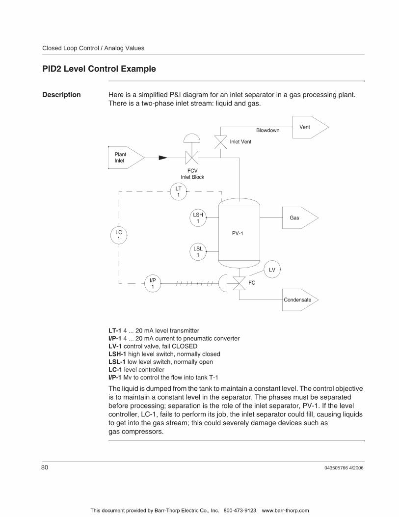
Closed Loop Control / Analog Values
80 043505766 4/2006
PID2 Level Control Example
Description Here is a simplified P&I diagram for an inlet separator in a gas processing plant. There is a two-phase inlet stream: liquid and gas.
LT-1 4 ... 20 mA level transmitterI/P-1 4 ... 20 mA current to pneumatic converterLV-1 control valve, fail CLOSEDLSH-1 high level switch, normally closedLSL-1 low level switch, normally openLC-1 level controllerI/P-1 Mv to control the flow into tank T-1
The liquid is dumped from the tank to maintain a constant level. The control objective is to maintain a constant level in the separator. The phases must be separated before processing; separation is the role of the inlet separator, PV-1. If the level controller, LC-1, fails to perform its job, the inlet separator could fill, causing liquids to get into the gas stream; this could severely damage devices such as gas compressors.
PlantInlet
FCVInlet Block
Inlet Vent
VentBlowdown
GasLSH1
LSL1
PV-1
FC
Condensate
LV
LT1
LC1
I/P1
This document provided by Barr-Thorp Electric Co., Inc. 800-473-9123 www.barr-thorp.com
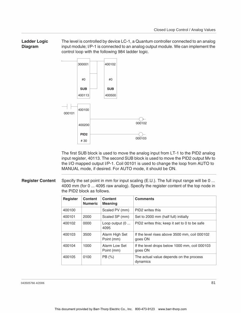
Closed Loop Control / Analog Values
043505766 4/2006 81
Ladder Logic Diagram
The level is controlled by device LC-1, a Quantum controller connected to an analog input module; I/P-1 is connected to an analog output module. We can implement the control loop with the following 984 ladder logic.
The first SUB block is used to move the analog input from LT-1 to the PID2 analog input register, 40113. The second SUB block is used to move the PID2 output Mv to the I/O mapped output I/P-1. Coil 00101 is used to change the loop from AUTO to MANUAL mode, if desired. For AUTO mode, it should be ON.
Register Content Specify the set point in mm for input scaling (E.U.). The full input range will be 0 ... 4000 mm (for 0 ... 4095 raw analog). Specify the register content of the top node in the PID2 block as follows.
000102
000101400100
PID2
400200
# 30
400102
SUB
#0
400500
300001
SUB
#0
400113
000103
Register ContentNumeric
ContentMeaning
Comments
400100 Scaled PV (mm) PID2 writes this
400101 2000 Scaled SP (mm) Set to 2000 mm (half full) initially
400102 0000 Loop output (0 ... 4095
PID2 writes this; keep it set to 0 to be safe
400103 3500 Alarm High Set Point (mm)
If the level rises above 3500 mm, coil 000102 goes ON
400104 1000 Alarm Low Set Point (mm)
If the level drops below 1000 mm, coil 000103 goes ON
400105 0100 PB (%) The actual value depends on the process dynamics
This document provided by Barr-Thorp Electric Co., Inc. 800-473-9123 www.barr-thorp.com
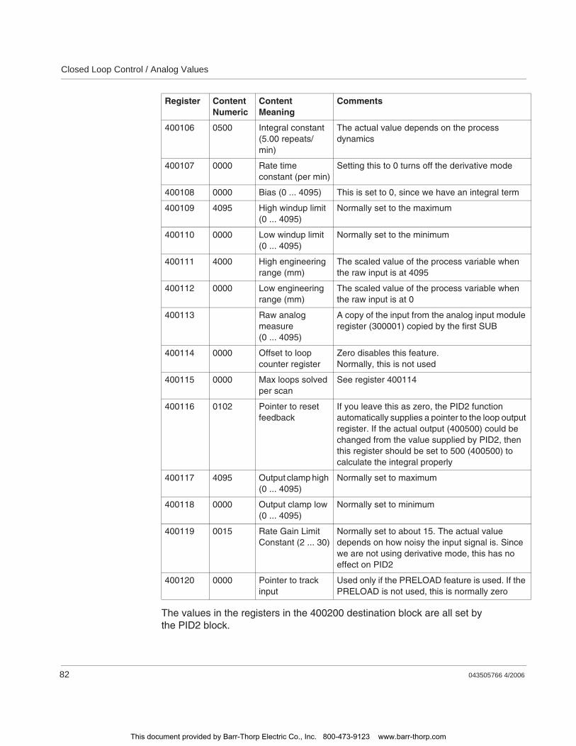
Closed Loop Control / Analog Values
82 043505766 4/2006
The values in the registers in the 400200 destination block are all set bythe PID2 block.
400106 0500 Integral constant (5.00 repeats/min)
The actual value depends on the process dynamics
400107 0000 Rate time constant (per min)
Setting this to 0 turns off the derivative mode
400108 0000 Bias (0 ... 4095) This is set to 0, since we have an integral term
400109 4095 High windup limit (0 ... 4095)
Normally set to the maximum
400110 0000 Low windup limit (0 ... 4095)
Normally set to the minimum
400111 4000 High engineering range (mm)
The scaled value of the process variable when the raw input is at 4095
400112 0000 Low engineering range (mm)
The scaled value of the process variable when the raw input is at 0
400113 Raw analog measure (0 ... 4095)
A copy of the input from the analog input module register (300001) copied by the first SUB
400114 0000 Offset to loop counter register
Zero disables this feature.Normally, this is not used
400115 0000 Max loops solved per scan
See register 400114
400116 0102 Pointer to reset feedback
If you leave this as zero, the PID2 function automatically supplies a pointer to the loop output register. If the actual output (400500) could be changed from the value supplied by PID2, then this register should be set to 500 (400500) to calculate the integral properly
400117 4095 Output clamp high (0 ... 4095)
Normally set to maximum
400118 0000 Output clamp low (0 ... 4095)
Normally set to minimum
400119 0015 Rate Gain Limit Constant (2 ... 30)
Normally set to about 15. The actual value depends on how noisy the input signal is. Since we are not using derivative mode, this has no effect on PID2
400120 0000 Pointer to track input
Used only if the PRELOAD feature is used. If the PRELOAD is not used, this is normally zero
Register ContentNumeric
ContentMeaning
Comments
This document provided by Barr-Thorp Electric Co., Inc. 800-473-9123 www.barr-thorp.com

043505766 4/2006 83
8Formatting Messages for ASCII READ/WRIT Operations
At a Glance
Introduction In this chapter you will find general information about formatting messages for ASCII READ/WRIT operations.
What's in this Chapter?
This chapter contains the following topics:
Topic Page
Formatting Messages for ASCII READ/WRIT Operations 84
Format Specifiers 85
Special Set-up Considerations for Control/Monitor Signals Format 88
This document provided by Barr-Thorp Electric Co., Inc. 800-473-9123 www.barr-thorp.com
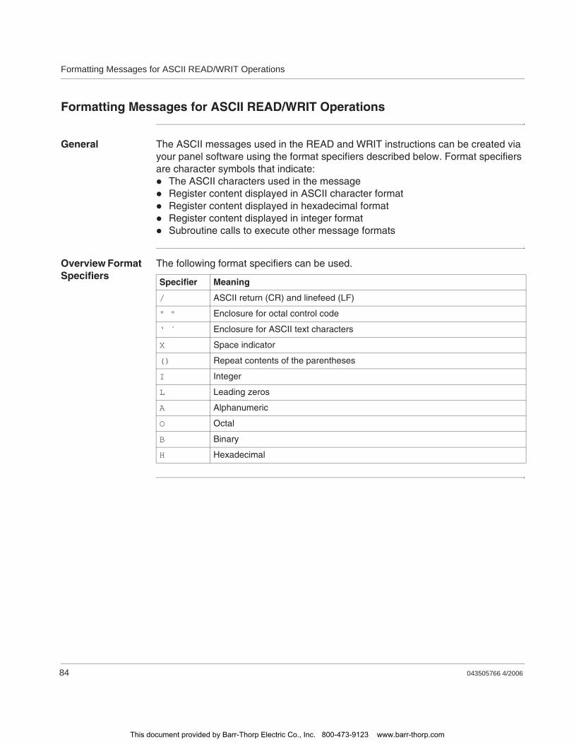
Formatting Messages for ASCII READ/WRIT Operations
84 043505766 4/2006
Formatting Messages for ASCII READ/WRIT Operations
General The ASCII messages used in the READ and WRIT instructions can be created via your panel software using the format specifiers described below. Format specifiers are character symbols that indicate:
The ASCII characters used in the messageRegister content displayed in ASCII character formatRegister content displayed in hexadecimal formatRegister content displayed in integer formatSubroutine calls to execute other message formats
Overview Format Specifiers
The following format specifiers can be used.
Specifier Meaning
/ ASCII return (CR) and linefeed (LF)
" " Enclosure for octal control code
‘ ´ Enclosure for ASCII text characters
X Space indicator
() Repeat contents of the parentheses
I Integer
L Leading zeros
A Alphanumeric
O Octal
B Binary
H Hexadecimal
This document provided by Barr-Thorp Electric Co., Inc. 800-473-9123 www.barr-thorp.com

Formatting Messages for ASCII READ/WRIT Operations
043505766 4/2006 85
Format Specifiers
Format Specifier /
ASCII return (CR) and linefeed (LF)
Format Specifier " "
Enclosure for octal control code
Format Specifier ‘ ´
Enclosure for ASCII text characters
Format Specifier X
Space indicator, e.g., 14X indicates 14 spaces left open from the point where the specifier occurs.
Field width None (defaults to 1)
Prefix None (defaults to 1)
Input format Outputs CR, LF; no ASCII characters accepted
Output format Outputs CR, LF
Field width Three digits enclosed in double quotes
Prefix None
Input format Accepts three octal control characters
Output format Outputs three octal control characters
Field width 1 ... 128 characters
Prefix None (defaults to 1)
Input format Inputs number of upper and/or lower case printable characters specified by the field width
Output format Outputs number of upper and/or lower case printable characters specified by the field width
Field width None (defaults to 1)
Prefix 1 ... 99 spaces
Input format Inputs specified number of spaces
Output format Outputs specified number of spaces
This document provided by Barr-Thorp Electric Co., Inc. 800-473-9123 www.barr-thorp.com
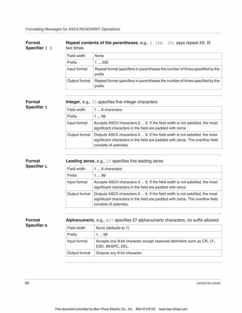
Formatting Messages for ASCII READ/WRIT Operations
86 043505766 4/2006
Format Specifier ( )
Repeat contents of the parentheses, e.g., 2 (4X, I5) says repeat 4X, I5 two times
Format Specifier I
Integer, e.g., I5 specifies five integer characters
Format Specifier L
Leading zeros, e.g., L5 specifies five leading zeros
Format Specifier A
Alphanumeric, e.g., A27 specifies 27 alphanumeric characters, no suffix allowed
Field width None
Prefix 1 ... 255
Input format Repeat format specifiers in parentheses the number of times specified by the prefix
Output format Repeat format specifiers in parentheses the number of times specified by the prefix
Field width 1 ... 8 characters
Prefix 1 ... 99
Input format Accepts ASCII characters 0 ... 9. If the field width is not satisfied, the most significant characters in the field are padded with zeros
Output format Outputs ASCII characters 0 ... 9. If the field width is not satisfied, the most significant characters in the field are padded with zeros. The overflow field consists of asterisks.
Field width None (defaults to 1)
Prefix 1 ... 99
Input format Accepts any 8-bit character except reserved delimiters such as CR, LF, ESC, BKSPC, DEL.
Output format Outputs any 8-bit character
This document provided by Barr-Thorp Electric Co., Inc. 800-473-9123 www.barr-thorp.com
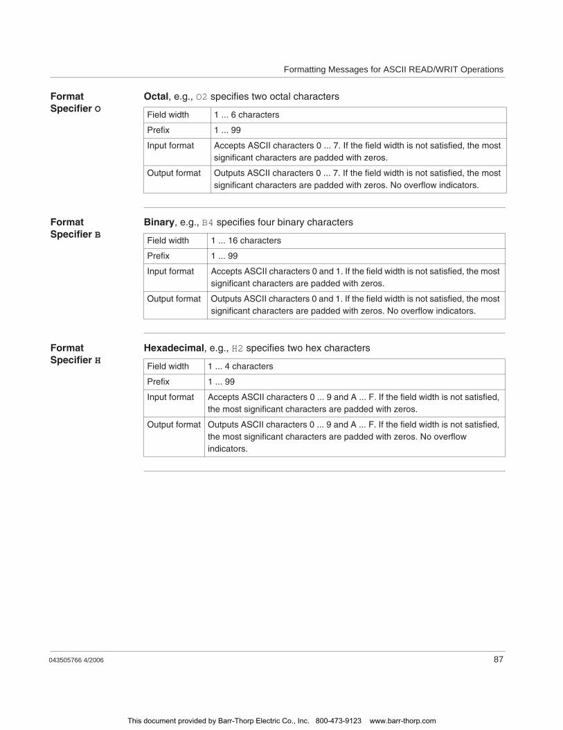
Formatting Messages for ASCII READ/WRIT Operations
043505766 4/2006 87
Format Specifier O
Octal, e.g., O2 specifies two octal characters
Format Specifier B
Binary, e.g., B4 specifies four binary characters
Format Specifier H
Hexadecimal, e.g., H2 specifies two hex characters
Field width 1 ... 6 characters
Prefix 1 ... 99
Input format Accepts ASCII characters 0 ... 7. If the field width is not satisfied, the most significant characters are padded with zeros.
Output format Outputs ASCII characters 0 ... 7. If the field width is not satisfied, the most significant characters are padded with zeros. No overflow indicators.
Field width 1 ... 16 characters
Prefix 1 ... 99
Input format Accepts ASCII characters 0 and 1. If the field width is not satisfied, the most significant characters are padded with zeros.
Output format Outputs ASCII characters 0 and 1. If the field width is not satisfied, the most significant characters are padded with zeros. No overflow indicators.
Field width 1 ... 4 characters
Prefix 1 ... 99
Input format Accepts ASCII characters 0 ... 9 and A ... F. If the field width is not satisfied, the most significant characters are padded with zeros.
Output format Outputs ASCII characters 0 ... 9 and A ... F. If the field width is not satisfied, the most significant characters are padded with zeros. No overflow indicators.
This document provided by Barr-Thorp Electric Co., Inc. 800-473-9123 www.barr-thorp.com
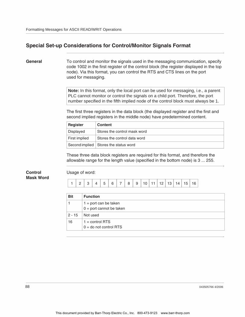
Formatting Messages for ASCII READ/WRIT Operations
88 043505766 4/2006
Special Set-up Considerations for Control/Monitor Signals Format
General To control and monitor the signals used in the messaging communication, specify code 1002 in the first register of the control block (the register displayed in the top node). Via this format, you can control the RTS and CTS lines on the port used for messaging.
The first three registers in the data block (the displayed register and the first and second implied registers in the middle node) have predetermined content.
These three data block registers are required for this format, and therefore the allowable range for the length value (specified in the bottom node) is 3 ... 255.
Control Mask Word
Usage of word:
Note: In this format, only the local port can be used for messaging, i.e., a parent PLC cannot monitor or control the signals on a child port. Therefore, the port number specified in the fifth implied node of the control block must always be 1.
Register Content
Displayed Stores the control mask word
First implied Stores the control data word
Second implied Stores the status word
Bit Function
1 1 = port can be taken0 = port cannot be taken
2 - 15 Not used
16 1 = control RTS0 = do not control RTS
1 2 3 4 5 6 7 8 9 10 11 12 13 14 15 16
This document provided by Barr-Thorp Electric Co., Inc. 800-473-9123 www.barr-thorp.com
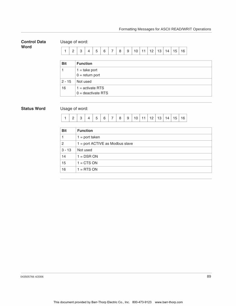
Formatting Messages for ASCII READ/WRIT Operations
043505766 4/2006 89
Control Data Word
Usage of word:
Status Word Usage of word:
Bit Function
1 1 = take port0 = return port
2 - 15 Not used
16 1 = activate RTS0 = deactivate RTS
1 2 3 4 5 6 7 8 9 10 11 12 13 14 15 16
Bit Function
1 1 = port taken
2 1 = port ACTIVE as Modbus slave
3 - 13 Not used
14 1 = DSR ON
15 1 = CTS ON
16 1 = RTS ON
1 2 3 4 5 6 7 8 9 10 11 12 13 14 15 16
This document provided by Barr-Thorp Electric Co., Inc. 800-473-9123 www.barr-thorp.com

Formatting Messages for ASCII READ/WRIT Operations
90 043505766 4/2006
This document provided by Barr-Thorp Electric Co., Inc. 800-473-9123 www.barr-thorp.com
043505766 4/2006 91
9Coils, Contacts and Interconnects
At a Glance
Introduction In this chapter you will find information about Coils, Contacts, and Interconnects, also called Shorts. Details of all the elements in the Ladder Logic Instruction Set appear in an alphabetical listing.
What's in this Chapter?
This chapter contains the following topics:
Topic Page
Coils 92
Contacts 94
Interconnects (Shorts) 96
This document provided by Barr-Thorp Electric Co., Inc. 800-473-9123 www.barr-thorp.com

Coils, Contacts and Interconnects
92 043505766 4/2006
Coils
Definition of Coils
A coil is a discrete output that is turned ON and OFF by power flow in the logic program. A single coil is tied to a 0x reference in the PLC’s state RAM. Because output values are updated in state RAM by the PLC, a coil may be used internally in the logic program or externally via the I/O map to a discrete output unit in the control system. When a coil is ON, it either passes power to a discrete output circuit or changes the state of an internal relay contact in state RAM.
There are two types of coils.A normal coilA memory-retentive, or latched, coil
This document provided by Barr-Thorp Electric Co., Inc. 800-473-9123 www.barr-thorp.com
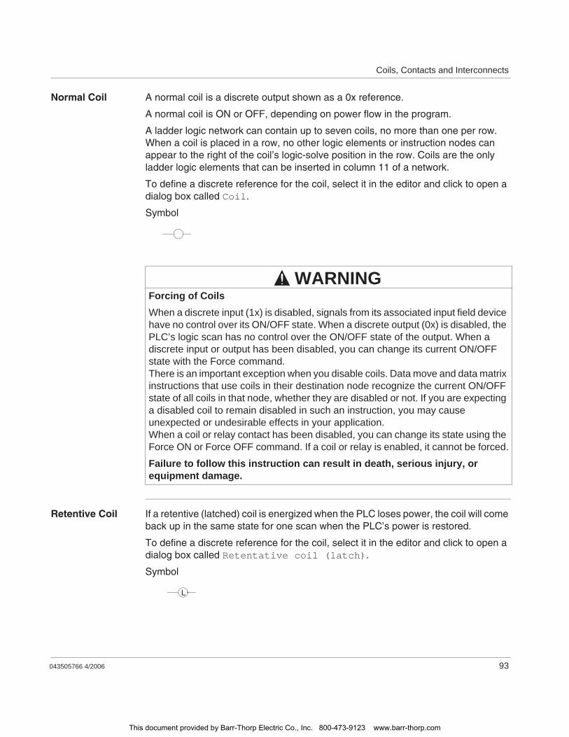
Coils, Contacts and Interconnects
043505766 4/2006 93
Normal Coil A normal coil is a discrete output shown as a 0x reference.
A normal coil is ON or OFF, depending on power flow in the program.
A ladder logic network can contain up to seven coils, no more than one per row. When a coil is placed in a row, no other logic elements or instruction nodes can appear to the right of the coil’s logic-solve position in the row. Coils are the only ladder logic elements that can be inserted in column 11 of a network.
To define a discrete reference for the coil, select it in the editor and click to open a dialog box called Coil.
Symbol
Retentive Coil If a retentive (latched) coil is energized when the PLC loses power, the coil will come back up in the same state for one scan when the PLC’s power is restored.
To define a discrete reference for the coil, select it in the editor and click to open a dialog box called Retentative coil (latch).
Symbol
Forcing of CoilsWhen a discrete input (1x) is disabled, signals from its associated input field device have no control over its ON/OFF state. When a discrete output (0x) is disabled, the PLC’s logic scan has no control over the ON/OFF state of the output. When a discrete input or output has been disabled, you can change its current ON/OFF state with the Force command.There is an important exception when you disable coils. Data move and data matrix instructions that use coils in their destination node recognize the current ON/OFF state of all coils in that node, whether they are disabled or not. If you are expecting a disabled coil to remain disabled in such an instruction, you may cause unexpected or undesirable effects in your application.When a coil or relay contact has been disabled, you can change its state using the Force ON or Force OFF command. If a coil or relay is enabled, it cannot be forced.
Failure to follow this instruction can result in death, serious injury, or equipment damage.
WARNING
L
This document provided by Barr-Thorp Electric Co., Inc. 800-473-9123 www.barr-thorp.com
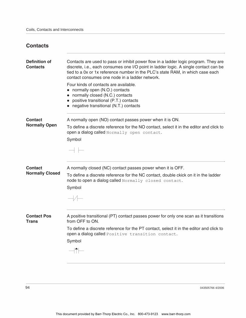
Coils, Contacts and Interconnects
94 043505766 4/2006
Contacts
Definition of Contacts
Contacts are used to pass or inhibit power flow in a ladder logic program. They are discrete, i.e., each consumes one I/O point in ladder logic. A single contact can be tied to a 0x or 1x reference number in the PLC’s state RAM, in which case each contact consumes one node in a ladder network.
Four kinds of contacts are available.normally open (N.O.) contactsnormally closed (N.C.) contactspositive transitional (P.T.) contactsnegative transitional (N.T.) contacts
Contact Normally Open
A normally open (NO) contact passes power when it is ON.
To define a discrete reference for the NO contact, select it in the editor and click to open a dialog called Normally open contact.
Symbol
Contact Normally Closed
A normally closed (NC) contact passes power when it is OFF.
To define a discrete reference for the NC contact, double ckick on it in the ladder node to open a dialog called Normally closed contact.
Symbol
Contact Pos Trans
A positive transitional (PT) contact passes power for only one scan as it transitions from OFF to ON.
To define a discrete reference for the PT contact, select it in the editor and click to open a dialog called Positive transition contact.
Symbol
This document provided by Barr-Thorp Electric Co., Inc. 800-473-9123 www.barr-thorp.com

Coils, Contacts and Interconnects
043505766 4/2006 95
Contact Neg Trans
A negative transitional (NT) contact passes power for only one scan as it transitions from ON to OFF.
To define a discrete reference for the NT contact, select it in the editor and click to open a dialog called Contact negative transition .
Symbol
This document provided by Barr-Thorp Electric Co., Inc. 800-473-9123 www.barr-thorp.com
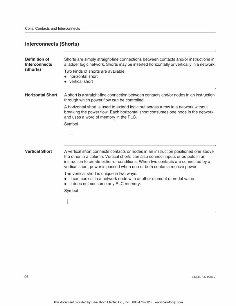
Coils, Contacts and Interconnects
96 043505766 4/2006
Interconnects (Shorts)
Definition of Interconnects (Shorts)
Shorts are simply straight-line connections between contacts and/or instructions in a ladder logic network. Shorts may be inserted horizontally or vertically in a network.
Two kinds of shorts are available.horizontal shortvertical short
Horizontal Short A short is a straight-line connection between contacts and/or nodes in an instruction through which power flow can be controlled.
A horizontal short is used to extend logic out across a row in a network without breaking the power flow. Each horizontal short consumes one node in the network, and uses a word of memory in the PLC.
Symbol
Vertical Short A vertical short connects contacts or nodes in an instruction positioned one above the other in a column. Vertical shorts can also connect inputs or outputs in an instruction to create either-or conditions. When two contacts are connected by a vertical short, power is passed when one or both contacts receive power.
The vertical short is unique in two ways.It can coexist in a network node with another element or nodal value.It does not consume any PLC memory.
Symbol
This document provided by Barr-Thorp Electric Co., Inc. 800-473-9123 www.barr-thorp.com

043505766 4/2006 97
10Interrupt Handling
Interrupt Handling
Interrupt-related Performance
The interrupt-related instructions operate with minimum processing overhead. The performance of interrupt-related instructions is especially critical. Using a interval timer interrupt (ITMR) instruction adds about 6% to the scan time of the scheduled ladder logic, this increase does not include the time required to execute the interrupt handler subroutine associated with the interrupt.
Interrupt Latency Time
The following table shows the minimum and maximum interrupt latency times you can expect.
These latency times assume only one interrupt at a time.
Interrupt Priorities
The PLC uses the following rules to choose which interrupt handler to execute in the event that multiple interrupts are received simultaneously.
An interrupt generated by an interrupt module has a higher priority than an interrupt generated by a timer.Interrupts from modules in lower slots of the local backplane have priority over interrupts from modules in the higher slots.
If the PLC is executing an interrupt handler subroutine when a higher priority interrupt is received, the current interrupt handler is completed before the new interrupt handler is begun.
ITMR overhead No work to do 60 ms/ms
Response time Minimum 98 ms
Maximum during logic solve and Modbus command reception 400 ms
Total overhead (not counting normal logic solve time) 155 ms
This document provided by Barr-Thorp Electric Co., Inc. 800-473-9123 www.barr-thorp.com

Interrupt Handling
98 043505766 4/2006
Instructions that Cannot Be Used in an Interrupt Handler
The following (nonreenterant) ladder logic instructions cannot be used inside an interrupt handler subroutine.
MSTRREAD / WRITPCFL / EMTHT1.0, T0.1, T.01, and T1MS timers (will not set error bit 2, timer results invalid)equation networksuser loadables (will not set error bit 2)
If any of these instructions are placed in an interrupt handler, the subroutine will be aborted, the error output on the ITMR or IMOD instruction that generated the interrupt will go ON, and bit 2 in the status register will be set.
Interrupt with BMDI/ID/IE
Three interrupt mask/unmask control instructions are available to help protect data in both the normal (scheduled) ladder logic and the (unscheduled) interrupt handling subroutine logic. These are the Interrupt Disable (ID) instruction, the Interrupt Enable (IE) instruction, and the Block Move with Interrupts Disabled (BMDI) instruction.
An interrupt that is executed in the timeframe after an ID instruction has been solved and before the next IE instruction has been solved is buffered. The execution of a buffered interrupt takes place at the time the IE instruction is solved. If two or more interrupts of the same type occur between the ID ... IE solve, the mask interrupt overrun error bit is set, and the subroutine initiated by the interrupts is executed only one time
The BMDI instruction can be used to mask both a timer-generated and local I/O-generated interrupts, perform a single block data move, then unmask the interrupts. It allows for the exchange of a block of data either within the subroutine or at one or more places in the scheduled logic program.
BMDI instructions can be used to reduce the time between the disable and enable of interrupts. For example, BMDI instructions can be used to protect the data used by the interrupt handler when the data is updated or read by Modbus, Modbus Plus, Peer Cop or Distributed I/O (DIO).
This document provided by Barr-Thorp Electric Co., Inc. 800-473-9123 www.barr-thorp.com
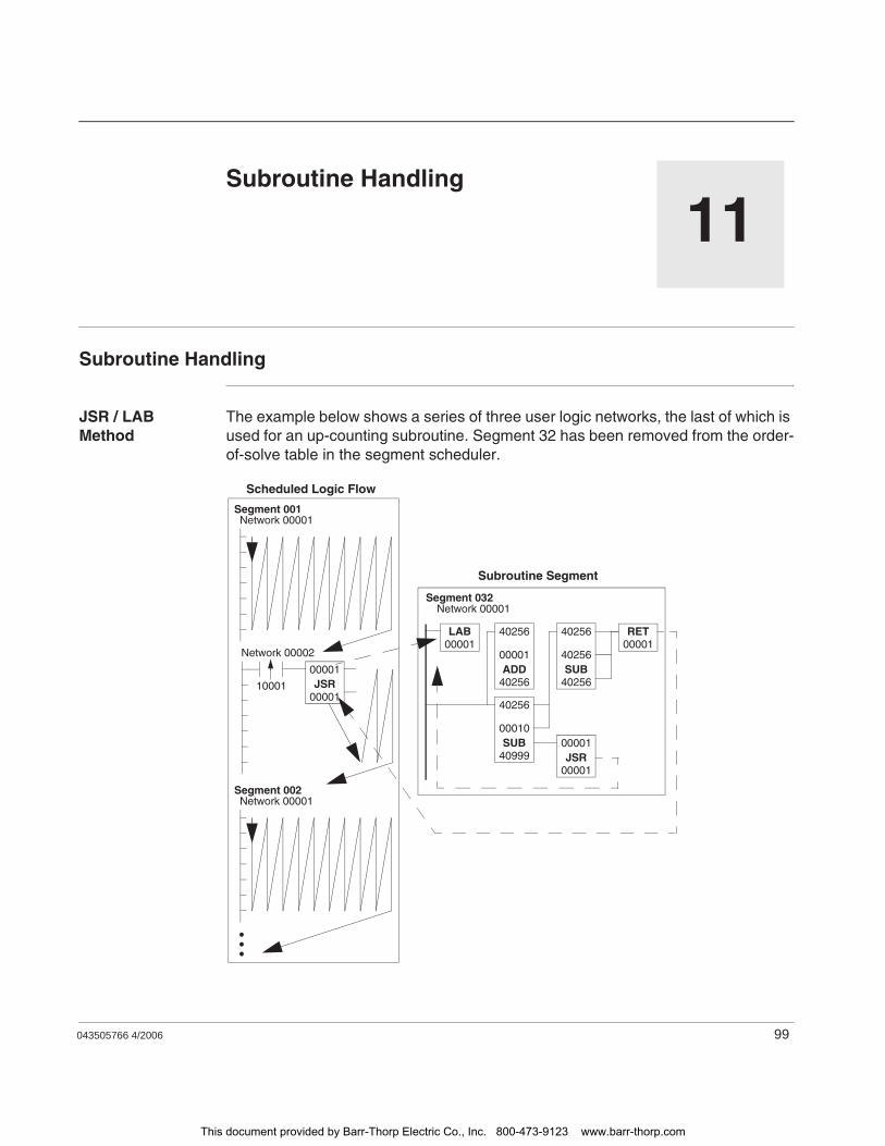
043505766 4/2006 99
11Subroutine Handling
Subroutine Handling
JSR / LAB Method
The example below shows a series of three user logic networks, the last of which is used for an up-counting subroutine. Segment 32 has been removed from the order-of-solve table in the segment scheduler.
Scheduled Logic Flow
Segment 001Network 00001
Network 00002
Segment 002Network 00001
00001
00001JSR10001
40256
40256
00001ADD
40256
40256
40256SUB
40256
40999
00010SUB
00001
00001JSR
00001RET
00001LAB
Segment 032Network 00001
Subroutine Segment
This document provided by Barr-Thorp Electric Co., Inc. 800-473-9123 www.barr-thorp.com

Subroutine Handling
100 043505766 4/2006
When input 100001 to the JSR block in network 2 of segment 1 transitions from OFF to ON, the logic scan jumps to subroutine #1 in network 1 of segment 32.
The subroutine will internally loop on itself ten times, counted by the ADD block. The first nine loops end with the JSR block in the subroutine (network 1 of segment 32) sending the scan back to the LAB block. Upon completion of the tenth loop, the RET block sends the logic scan back to the scheduled logic at the JSR node in network 2 of segment 1.
This document provided by Barr-Thorp Electric Co., Inc. 800-473-9123 www.barr-thorp.com
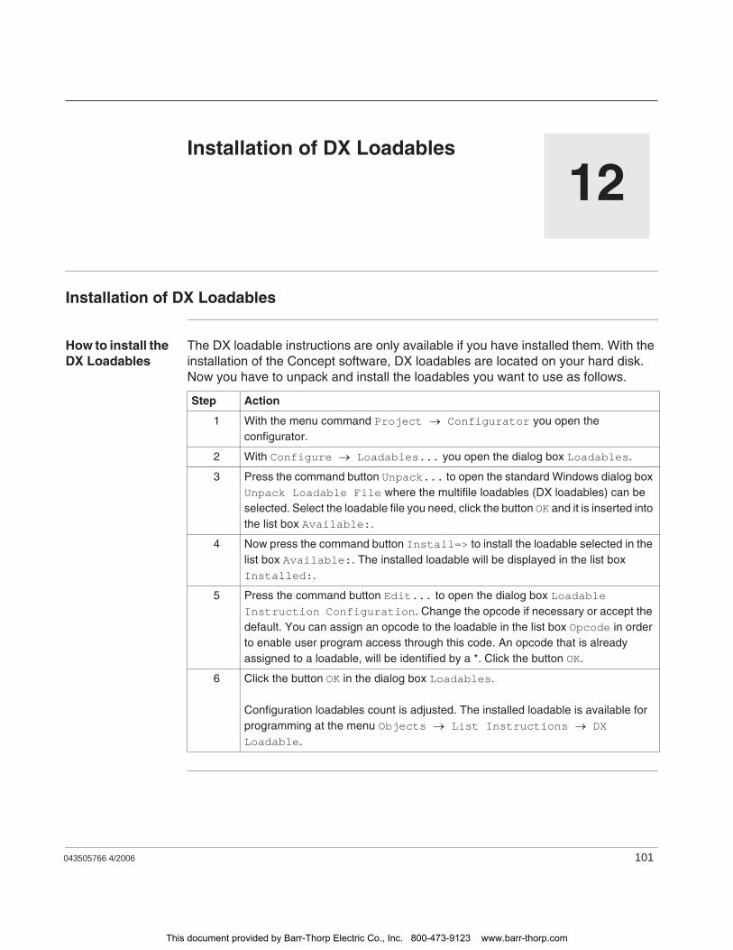
043505766 4/2006 101
12Installation of DX Loadables
Installation of DX Loadables
How to install the DX Loadables
The DX loadable instructions are only available if you have installed them. With the installation of the Concept software, DX loadables are located on your hard disk. Now you have to unpack and install the loadables you want to use as follows.
Step Action
1 With the menu command Project Configurator you open the configurator.
2 With Configure Loadables... you open the dialog box Loadables.
3 Press the command button Unpack... to open the standard Windows dialog box Unpack Loadable File where the multifile loadables (DX loadables) can be selected. Select the loadable file you need, click the button OK and it is inserted into the list box Available:.
4 Now press the command button Install=> to install the loadable selected in the list box Available:. The installed loadable will be displayed in the list box Installed:.
5 Press the command button Edit... to open the dialog box Loadable Instruction Configuration. Change the opcode if necessary or accept the default. You can assign an opcode to the loadable in the list box Opcode in order to enable user program access through this code. An opcode that is already assigned to a loadable, will be identified by a *. Click the button OK.
6 Click the button OK in the dialog box Loadables.
Configuration loadables count is adjusted. The installed loadable is available for programming at the menu Objects List Instructions DX Loadable.
This document provided by Barr-Thorp Electric Co., Inc. 800-473-9123 www.barr-thorp.com

Installation of DX Loadables
102 043505766 4/2006
This document provided by Barr-Thorp Electric Co., Inc. 800-473-9123 www.barr-thorp.com
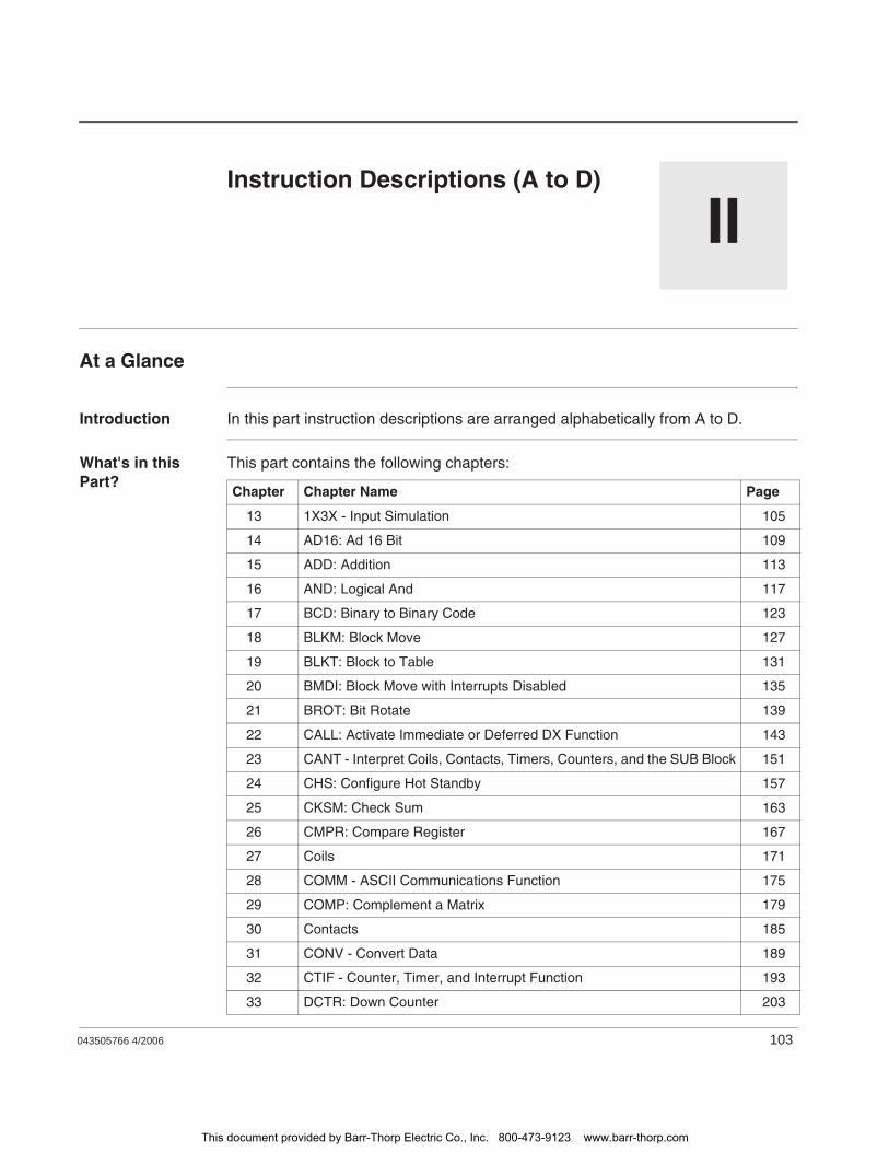
043505766 4/2006 103
IIInstruction Descriptions (A to D)
At a Glance
Introduction In this part instruction descriptions are arranged alphabetically from A to D.
What's in this Part?
This part contains the following chapters:
Chapter Chapter Name Page
13 1X3X - Input Simulation 105
14 AD16: Ad 16 Bit 109
15 ADD: Addition 113
16 AND: Logical And 117
17 BCD: Binary to Binary Code 123
18 BLKM: Block Move 127
19 BLKT: Block to Table 131
20 BMDI: Block Move with Interrupts Disabled 135
21 BROT: Bit Rotate 139
22 CALL: Activate Immediate or Deferred DX Function 143
23 CANT - Interpret Coils, Contacts, Timers, Counters, and the SUB Block 151
24 CHS: Configure Hot Standby 157
25 CKSM: Check Sum 163
26 CMPR: Compare Register 167
27 Coils 171
28 COMM - ASCII Communications Function 175
29 COMP: Complement a Matrix 179
30 Contacts 185
31 CONV - Convert Data 189
32 CTIF - Counter, Timer, and Interrupt Function 193
33 DCTR: Down Counter 203
This document provided by Barr-Thorp Electric Co., Inc. 800-473-9123 www.barr-thorp.com
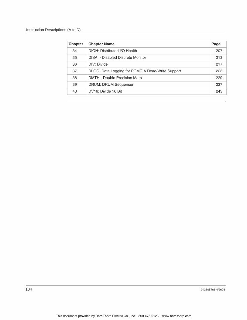
Instruction Descriptions (A to D)
104 043505766 4/2006
34 DIOH: Distributed I/O Health 207
35 DISA - Disabled Discrete Monitor 213
36 DIV: Divide 217
37 DLOG: Data Logging for PCMCIA Read/Write Support 223
38 DMTH - Double Precision Math 229
39 DRUM: DRUM Sequencer 237
40 DV16: Divide 16 Bit 243
Chapter Chapter Name Page
This document provided by Barr-Thorp Electric Co., Inc. 800-473-9123 www.barr-thorp.com
043505766 4/2006 105
131X3X - Input Simulation
At A Glance
Introduction This chapter describes the instruction 1X3X.
What's in this Chapter?
This chapter contains the following topics:
Topic Page
Short Description: 1X3X - Input Simulation 106
Representation: 1X3X - Input Simulation 107
This document provided by Barr-Thorp Electric Co., Inc. 800-473-9123 www.barr-thorp.com

1X3X - Input Simulation
106 043505766 4/2006
Short Description: 1X3X - Input Simulation
Function Description
The Input Simulation instruction provides a simple method to simulate 1xxxx and 3xxx input data values. This block is similar to a Block Move, the BLKM instruction. When the Control Input receives power, the source table is copied to the destination (input) table.
This document provided by Barr-Thorp Electric Co., Inc. 800-473-9123 www.barr-thorp.com
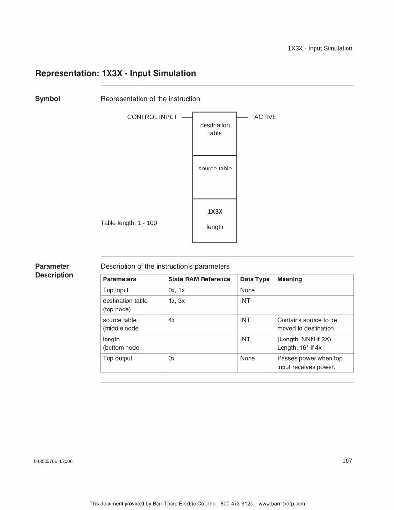
1X3X - Input Simulation
043505766 4/2006 107
Representation: 1X3X - Input Simulation
Symbol Representation of the instruction
Parameter Description
Description of the instruction’s parameters
CONTROL INPUT ACTIVEdestination
table
source table
1X3X
lengthTable length: 1 - 100
Parameters State RAM Reference Data Type Meaning
Top input 0x, 1x None
destination table(top node)
1x, 3x INT
source table(middle node
4x INT Contains source to be moved to destination
length(bottom node
INT (Length: NNN if 3X)Length: 16* if 4x
Top output 0x None Passes power when top input receives power.
This document provided by Barr-Thorp Electric Co., Inc. 800-473-9123 www.barr-thorp.com

1X3X - Input Simulation
108 043505766 4/2006
This document provided by Barr-Thorp Electric Co., Inc. 800-473-9123 www.barr-thorp.com

043505766 4/2006 109
14AD16: Ad 16 Bit
At a Glance
Introduction This chapter describes the instruction AD16.
What's in this Chapter?
This chapter contains the following topics:
Topic Page
Short Description 110
Representation: AD16 - 16-bit Addition 111
This document provided by Barr-Thorp Electric Co., Inc. 800-473-9123 www.barr-thorp.com

AD16: Ad 16 Bit
110 043505766 4/2006
Short Description
Function Description
The AD16 instruction performs signed or unsigned 16-bit addition on value 1 (its top node) and value 2 (its middle node), then posts the sum in a 4x holding register in the bottom node.
This document provided by Barr-Thorp Electric Co., Inc. 800-473-9123 www.barr-thorp.com
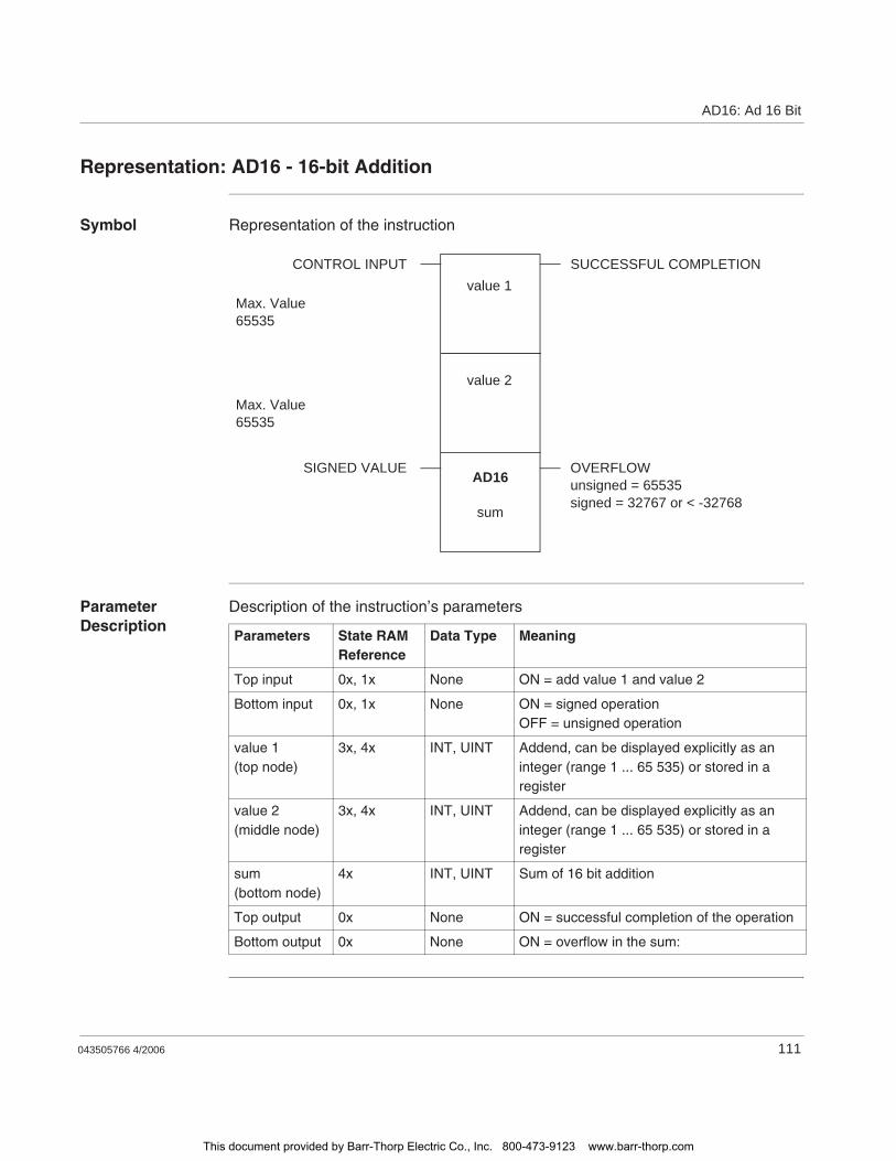
AD16: Ad 16 Bit
043505766 4/2006 111
Representation: AD16 - 16-bit Addition
Symbol Representation of the instruction
Parameter Description
Description of the instruction’s parameters
AD16
sum
value 2
value 1CONTROL INPUT SUCCESSFUL COMPLETION
OVERFLOWunsigned = 65535signed = 32767 or < -32768
SIGNED VALUE
Max. Value65535
Max. Value65535
Parameters State RAM Reference
Data Type Meaning
Top input 0x, 1x None ON = add value 1 and value 2
Bottom input 0x, 1x None ON = signed operationOFF = unsigned operation
value 1(top node)
3x, 4x INT, UINT Addend, can be displayed explicitly as an integer (range 1 ... 65 535) or stored in a register
value 2(middle node)
3x, 4x INT, UINT Addend, can be displayed explicitly as an integer (range 1 ... 65 535) or stored in a register
sum(bottom node)
4x INT, UINT Sum of 16 bit addition
Top output 0x None ON = successful completion of the operation
Bottom output 0x None ON = overflow in the sum:
This document provided by Barr-Thorp Electric Co., Inc. 800-473-9123 www.barr-thorp.com

AD16: Ad 16 Bit
112 043505766 4/2006
This document provided by Barr-Thorp Electric Co., Inc. 800-473-9123 www.barr-thorp.com

043505766 4/2006 113
15ADD: Addition
At a Glance
Introduction This chapter describes the instruction ADD.
What's in this Chapter?
This chapter contains the following topics:
Topic Page
Short Description 114
Representation: ADD - Single Precision Add 115
This document provided by Barr-Thorp Electric Co., Inc. 800-473-9123 www.barr-thorp.com

ADD: Addition
114 043505766 4/2006
Short Description
Function Description
The ADD instruction adds unsigned value 1 (its top node) to unsigned value 2 (its middle node) and stores the sum in a holding register in the bottom node.
This document provided by Barr-Thorp Electric Co., Inc. 800-473-9123 www.barr-thorp.com
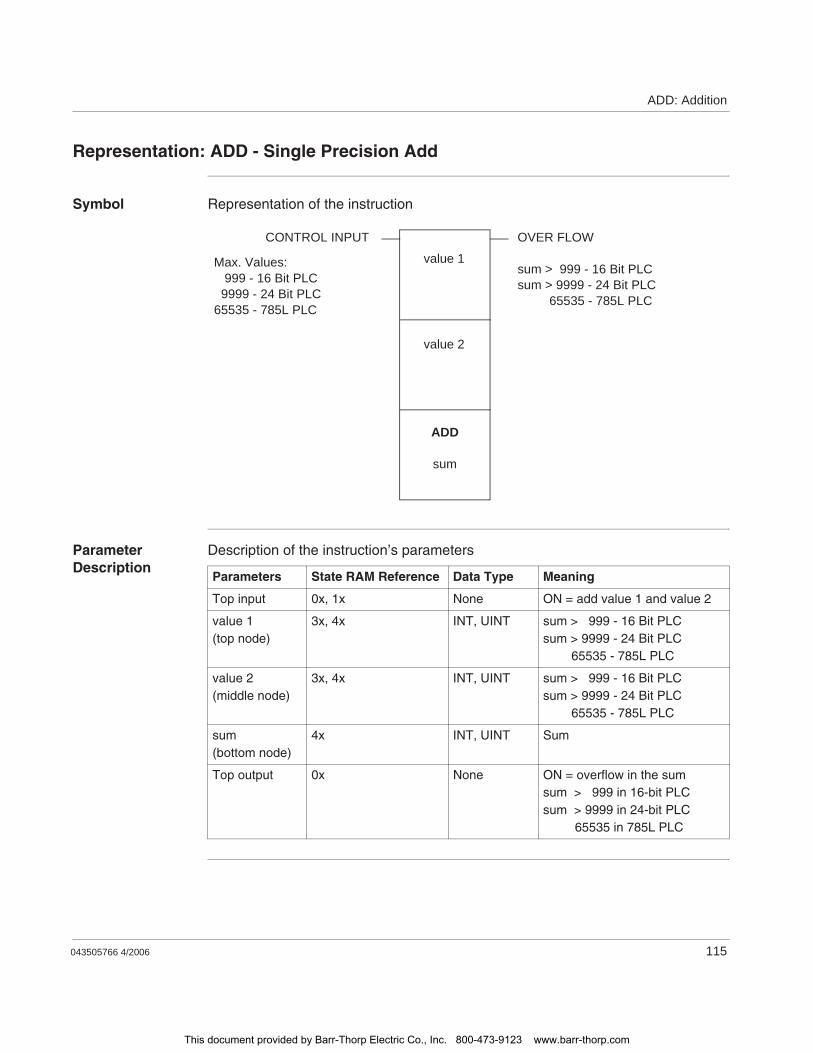
ADD: Addition
043505766 4/2006 115
Representation: ADD - Single Precision Add
Symbol Representation of the instruction
Parameter Description
Description of the instruction’s parameters
ADD
sum
value 2
value 1
CONTROL INPUT OVER FLOW
sum > 999 - 16 Bit PLCsum > 9999 - 24 Bit PLC 65535 - 785L PLC
Max. Values: 999 - 16 Bit PLC 9999 - 24 Bit PLC65535 - 785L PLC
Parameters State RAM Reference Data Type Meaning
Top input 0x, 1x None ON = add value 1 and value 2
value 1(top node)
3x, 4x INT, UINT sum > 999 - 16 Bit PLCsum > 9999 - 24 Bit PLC 65535 - 785L PLC
value 2(middle node)
3x, 4x INT, UINT sum > 999 - 16 Bit PLCsum > 9999 - 24 Bit PLC 65535 - 785L PLC
sum(bottom node)
4x INT, UINT Sum
Top output 0x None ON = overflow in the sumsum > 999 in 16-bit PLCsum > 9999 in 24-bit PLC 65535 in 785L PLC
This document provided by Barr-Thorp Electric Co., Inc. 800-473-9123 www.barr-thorp.com

ADD: Addition
116 043505766 4/2006
This document provided by Barr-Thorp Electric Co., Inc. 800-473-9123 www.barr-thorp.com

043505766 4/2006 117
16AND: Logical And
At a Glance
Introduction This chapter describes the instruction AND.
What's in this Chapter?
This chapter contains the following topics:
Topic Page
Short Description 118
Representation: AND - Logical And 119
Parameter Description 121
This document provided by Barr-Thorp Electric Co., Inc. 800-473-9123 www.barr-thorp.com
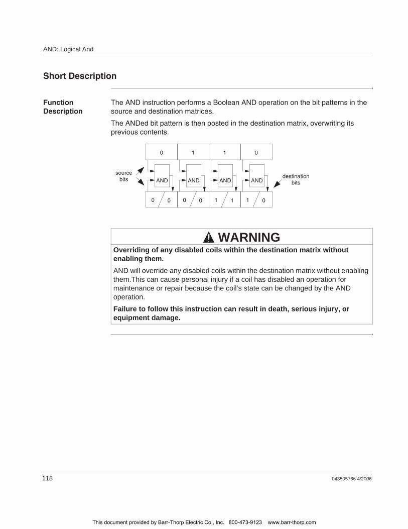
AND: Logical And
118 043505766 4/2006
Short Description
Function Description
The AND instruction performs a Boolean AND operation on the bit patterns in the source and destination matrices.
The ANDed bit pattern is then posted in the destination matrix, overwriting its previous contents.
Overriding of any disabled coils within the destination matrix without enabling them.AND will override any disabled coils within the destination matrix without enabling them.This can cause personal injury if a coil has disabled an operation for maintenance or repair because the coil’s state can be changed by the AND operation.
Failure to follow this instruction can result in death, serious injury, or equipment damage.
0 1 1 0
0 0
AND
0 0
AND
1 1
AND
1 0
ANDdestination
bits
sourcebits
WARNING
This document provided by Barr-Thorp Electric Co., Inc. 800-473-9123 www.barr-thorp.com
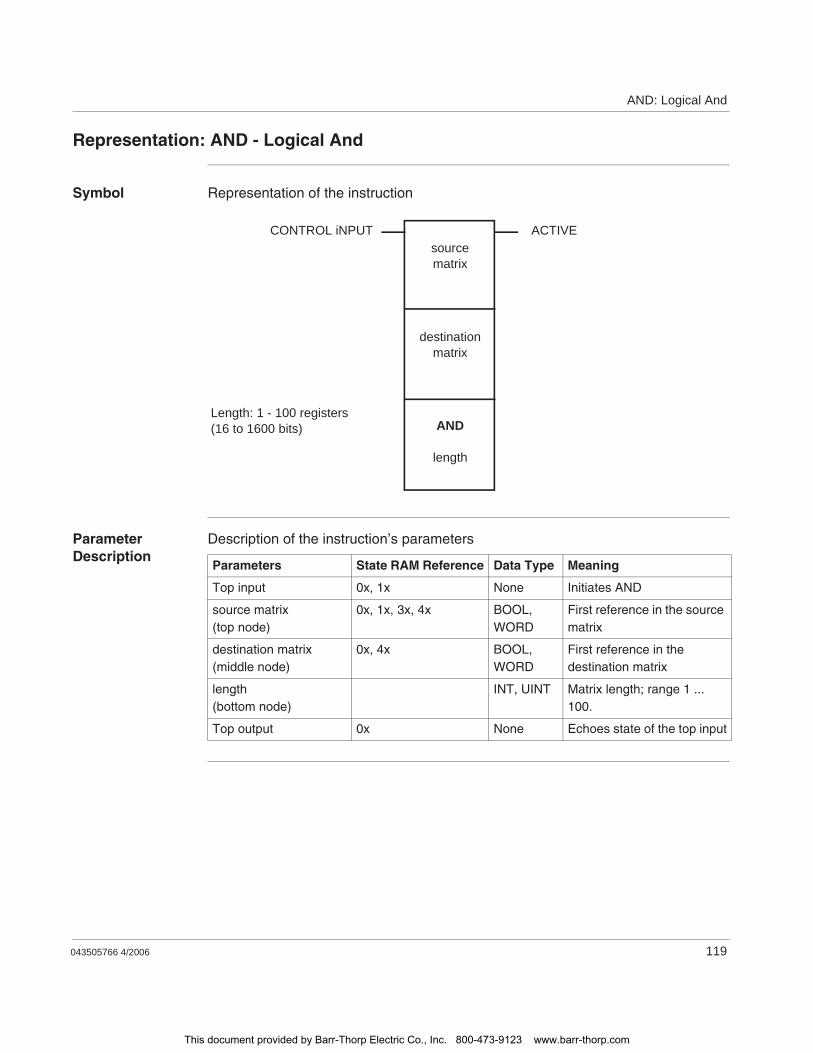
AND: Logical And
043505766 4/2006 119
Representation: AND - Logical And
Symbol Representation of the instruction
Parameter Description
Description of the instruction’s parameters
CONTROL iNPUT ACTIVE
Length: 1 - 100 registers(16 to 1600 bits)
sourcematrix
destinationmatrix
AND
length
Parameters State RAM Reference Data Type Meaning
Top input 0x, 1x None Initiates AND
source matrix(top node)
0x, 1x, 3x, 4x BOOL, WORD
First reference in the source matrix
destination matrix(middle node)
0x, 4x BOOL, WORD
First reference in the destination matrix
length(bottom node)
INT, UINT Matrix length; range 1 ... 100.
Top output 0x None Echoes state of the top input
This document provided by Barr-Thorp Electric Co., Inc. 800-473-9123 www.barr-thorp.com
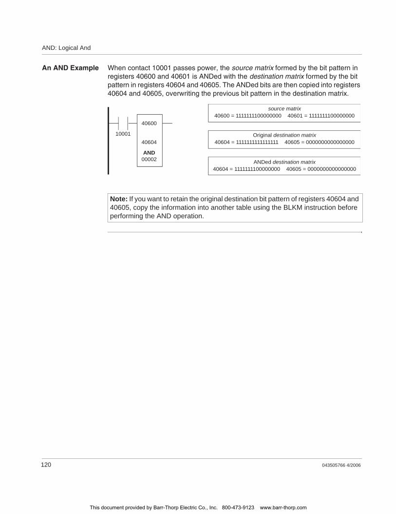
AND: Logical And
120 043505766 4/2006
An AND Example When contact 10001 passes power, the source matrix formed by the bit pattern in registers 40600 and 40601 is ANDed with the destination matrix formed by the bit pattern in registers 40604 and 40605. The ANDed bits are then copied into registers 40604 and 40605, overwriting the previous bit pattern in the destination matrix.
Note: If you want to retain the original destination bit pattern of registers 40604 and 40605, copy the information into another table using the BLKM instruction before performing the AND operation.
source matrix40600 = 1111111100000000 40601 = 1111111100000000
Original destination matrix40604 = 1111111111111111 40605 = 0000000000000000
ANDed destination matrix40604 = 1111111100000000 40605 = 0000000000000000
40600
40604
00002
10001
AND
This document provided by Barr-Thorp Electric Co., Inc. 800-473-9123 www.barr-thorp.com

AND: Logical And
043505766 4/2006 121
Parameter Description
Matrix Length (Bottom Node)
The integer entered in the bottom node specifies the matrix length, i.e. the number of registers or 16-bit words in the two matrices. The matrix length can be in the range 1 ... 100. A length of 2 indicates that 32 bits in each matrix will be ANDed.
This document provided by Barr-Thorp Electric Co., Inc. 800-473-9123 www.barr-thorp.com

AND: Logical And
122 043505766 4/2006
This document provided by Barr-Thorp Electric Co., Inc. 800-473-9123 www.barr-thorp.com

043505766 4/2006 123
17BCD: Binary to Binary Code
At a Glance
Introduction This chapter describes the instruction BCD.
What's in this Chapter?
This chapter contains the following topics:
Topic Page
Short Description 124
Representation: BCD - Binary Coded Decimal Conversion 125
This document provided by Barr-Thorp Electric Co., Inc. 800-473-9123 www.barr-thorp.com

BCD: Binary to Binary Code
124 043505766 4/2006
Short Description
Function Description
The BCD instruction can be used to convert a binary value to a binary coded decimal (BCD) value or a BCD value to a binary value. The type of conversion to be performed is controlled by the state of the bottom input.
This document provided by Barr-Thorp Electric Co., Inc. 800-473-9123 www.barr-thorp.com
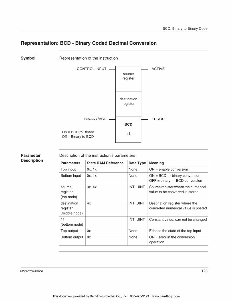
BCD: Binary to Binary Code
043505766 4/2006 125
Representation: BCD - Binary Coded Decimal Conversion
Symbol Representation of the instruction
Parameter Description
Description of the instruction’s parameters
CONTROL INPUT
BINARY/BCD
ACTIVE
On = BCD to BinaryOff = Binary to BCD
ERROR
sourceregister
destinationregister
BCD
#1
Parameters State RAM Reference Data Type Meaning
Top input 0x, 1x None ON = enable conversion
Bottom input 0x, 1x None ON = BCD binary conversionOFF = binary BCD conversion
source register(top node)
3x, 4x INT, UINT Source register where the numerical value to be converted is stored
destination register(middle node)
4x INT, UINT Destination register where the converted numerical value is posted
#1(bottom node)
INT, UINT Constant value, can not be changed
Top output 0x None Echoes the state of the top input
Bottom output 0x None ON = error in the conversion operation
This document provided by Barr-Thorp Electric Co., Inc. 800-473-9123 www.barr-thorp.com

BCD: Binary to Binary Code
126 043505766 4/2006
This document provided by Barr-Thorp Electric Co., Inc. 800-473-9123 www.barr-thorp.com

043505766 4/2006 127
18BLKM: Block Move
At a Glance
Introduction This chapter describes the instruction BLKM.
What's in this Chapter?
This chapter contains the following topics:
Topic Page
Short Description 128
Representation: BLKM - Block Move 129
This document provided by Barr-Thorp Electric Co., Inc. 800-473-9123 www.barr-thorp.com
BLKM: Block Move
128 043505766 4/2006
Short Description
Function Description
The BLKM (block move) instruction copies the entire contents of a source table to a destination table in one scan.
Overriding of any disabled coils within a destination table without enabling them.BLKM will override any disabled coils within a destination table without enabling them. This can cause injury if a coil has been disabled for repair or maintenance because the coil’s state can change as a result of the BLKM instruction.
Failure to follow this instruction can result in death, serious injury, or equipment damage.
WARNING
This document provided by Barr-Thorp Electric Co., Inc. 800-473-9123 www.barr-thorp.com
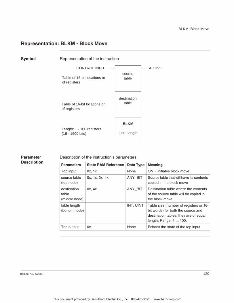
BLKM: Block Move
043505766 4/2006 129
Representation: BLKM - Block Move
Symbol Representation of the instruction
Parameter Description
Description of the instruction’s parameters
BLKM
table length
destinationtable
sourcetable
CONTROL INPUT ACTIVE
Length: 1 - 100 registers(16 - 1600 bits)
Table of 16-bit locations or of registers
Table of 16-bit locations or of registers
Parameters State RAM Reference Data Type Meaning
Top input 0x, 1x None ON = initiates block move
source table(top node)
0x, 1x, 3x, 4x ANY_BIT Source table that will have its contents copied in the block move
destination table(middle node)
0x, 4x ANY_BIT Destination table where the contents of the source table will be copied in the block move
table length(bottom node)
INT, UINT Table size (number of registers or 16-bit words) for both the source and destination tables; they are of equal length. Range: 1 ... 100.
Top output 0x None Echoes the state of the top input
This document provided by Barr-Thorp Electric Co., Inc. 800-473-9123 www.barr-thorp.com

BLKM: Block Move
130 043505766 4/2006
This document provided by Barr-Thorp Electric Co., Inc. 800-473-9123 www.barr-thorp.com

043505766 4/2006 131
19BLKT: Block to Table
At a Glance
Introduction This chapter describes the instruction BLKT.
What's in this Chapter?
This chapter contains the following topics:
Topic Page
Short Description 132
Representation: BLKT - Block-to-Table Move 133
Parameter Description 134
This document provided by Barr-Thorp Electric Co., Inc. 800-473-9123 www.barr-thorp.com
BLKT: Block to Table
132 043505766 4/2006
Short Description
Function Description
The BLKT (block-to-table) instruction combines the functions of R T and BLKM in a single instruction. In one scan, it can copy data from a source block to a destination block in a table. The source block is of a fixed length. The block within the table is of the same length, but the overall length of the table is limited only by the number of registers in your system configuration.
All the 4x registers in your PLC can be corrupted with data copied from the source block.BLKT is a powerful instruction that can corrupt all the 4x registers in your PLC with data copied from the source block. You should use external logic in conjunction with the middle or bottom input to confine the value in the pointer to a safe range.
Failure to follow this instruction can result in death, serious injury, or equipment damage.
WARNING
This document provided by Barr-Thorp Electric Co., Inc. 800-473-9123 www.barr-thorp.com
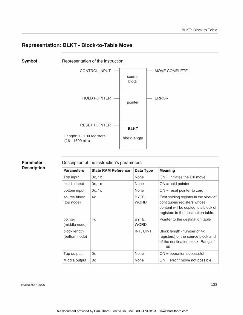
BLKT: Block to Table
043505766 4/2006 133
Representation: BLKT - Block-to-Table Move
Symbol Representation of the instruction
Parameter Description
Description of the instruction’s parameters
BLKT
block length
pointer
sourceblock
CONTROL INPUT MOVE COMPLETE
RESET POINTER
ERRORHOLD POINTER
Length: 1 - 100 registers(16 - 1600 bits)
Parameters State RAM Reference Data Type Meaning
Top input 0x, 1x None ON = initiates the DX move
middle input 0x, 1x None ON = hold pointer
bottom input 0x, 1x None ON = reset pointer to zero
source block(top node)
4x BYTE, WORD
First holding register in the block of contiguous registers whose content will be copied to a block of registers in the destination table.
pointer(middle node)
4x BYTE, WORD
Pointer to the destination table
block length(bottom node)
INT, UINT Block length (number of 4x registers) of the source block and of the destination block. Range: 1 ... 100.
Top output 0x None ON = operation successful
Middle output 0x None ON = error / move not possible
This document provided by Barr-Thorp Electric Co., Inc. 800-473-9123 www.barr-thorp.com
BLKT: Block to Table
134 043505766 4/2006
Parameter Description
Middle and Bottom Input
The middle and bottom input can be used to control the pointer so that source data is not copied into registers that are needed for other purposes in the logic program.
When the middle input is ON, the value in the pointer register is frozen while the BLKT operation continues. This causes new data being copied to the destination to overwrite the block data copied on the previous scan.
When the bottom input is ON, the value in the pointer register is reset to zero. This causes the BLKT operation to copy source data into the first block of registers in the destination table.
Pointer (Middle Node)
The 4x register entered in the middle node is the pointer to the destination table. The first register in the destination table is the next contiguous register after the pointer, e.g. if the pointer register is 400107, then the first register in the destination table is 400108.
The value stored in the pointer register indicates where in the destination table the source data will begin to be copied. This value specifies the block number within the destination table.
Note: The destination table is segmented into a series of register blocks, each of which is the same length as the source block. Therefore, the size of the destination table is a multiple of the length of the source block, but its overall size is not specifically defined in the instruction. If left uncontrolled, the destination table could consume all the 4x registers available in the PLC configuration.
This document provided by Barr-Thorp Electric Co., Inc. 800-473-9123 www.barr-thorp.com
043505766 4/2006 135
20BMDI: Block Move with Interrupts Disabled
At a Glance
Introduction This chapter describes the instruction BMDI.
What's in this Chapter?
This chapter contains the following topics:
Topic Page
Short Description: BMDI - Block Move Interrupts Disabled 136
Representation: BMDI - Block Move Interrupts Disabled 137
This document provided by Barr-Thorp Electric Co., Inc. 800-473-9123 www.barr-thorp.com

BMDI: Block Move with Interrupts Disabled
136 043505766 4/2006
Short Description: BMDI - Block Move Interrupts Disabled
Function Description
The BMDI instruction masks the interrupt, initiates a block move (BLKM) operation, then unmasks the interrupts.
This document provided by Barr-Thorp Electric Co., Inc. 800-473-9123 www.barr-thorp.com

BMDI: Block Move with Interrupts Disabled
043505766 4/2006 137
Representation: BMDI - Block Move Interrupts Disabled
Symbol Representation of the instruction
Parameter Description
Description of the instruction’s parameters
BMDI
table length
destinationtable
sourcetable
CONTROL INPUT ACTIVE
Length: 1 - 100 registers(16 - 1600 bits)
Table of 16-bit locations or of registers
Table of 16-bit locations or of registers
Parameters State RAM Reference Data Type Meaning
Top input 0x, 1x None ON = masks interrupt, initiates a block move, then unmasks the interrupts
source table (top node)
0x, 1x, 3x, 4x INT, UINT, WORD
Source table that will have its contents copied in the block move
destination table(middle node)
0x, 4x INT, UINT, WORD
Destination table where the contents of the source table will be copied in the block move
table length(bottom node)
INT, UINT Integer value, specifies the table size, i.e. the number of registers, in the source and destination tables (they are of equal length). Range: 1 ... 100.
Top output 0x None Echoes the state of the top input
This document provided by Barr-Thorp Electric Co., Inc. 800-473-9123 www.barr-thorp.com

BMDI: Block Move with Interrupts Disabled
138 043505766 4/2006
This document provided by Barr-Thorp Electric Co., Inc. 800-473-9123 www.barr-thorp.com
043505766 4/2006 139
21BROT: Bit Rotate
At a Glance
Introduction This chapter describes the instruction BROT.
What's in this Chapter?
This chapter contains the following topics:
Topic Page
Short Description 140
Representation: BROT - Bit Rotate 141
Parameter Description 142
This document provided by Barr-Thorp Electric Co., Inc. 800-473-9123 www.barr-thorp.com

BROT: Bit Rotate
140 043505766 4/2006
Short Description
Function Description
The BROT (bit rotate) instruction shifts the bit pattern in a source matrix, then posts the shifted bit pattern in a destination matrix. The bit pattern shifts left or right by one position per scan.
Overriding of any disabled coils within a destination matrix without enabling them.BROT will override any disabled coils within a destination matrix without enabling them. This can cause injury if a coil has been disabled for repair or maintenance if BROT unexpectedly changes the coil’s state.
Failure to follow this instruction can result in death, serious injury, or equipment damage.
WARNING
This document provided by Barr-Thorp Electric Co., Inc. 800-473-9123 www.barr-thorp.com
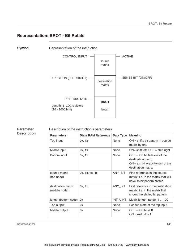
BROT: Bit Rotate
043505766 4/2006 141
Representation: BROT - Bit Rotate
Symbol Representation of the instruction
Parameter Description
Description of the instruction’s parameters
BROT
length
destinationmatrix
sourcematrix
CONTROL INPUT ACTIVE
SHIFT/ROTATE
SENSE BIT (ON/OFF)DIRECTION (LEFT/RIGHT)
Length: 1 -100 registers(16 - 1600 bits)
Parameters State RAM Reference Data Type Meaning
Top input 0x, 1x None ON = shifts bit pattern in source matrix by one
Middle input 0x, 1x None ON= shift left, OFF = shift right
Bottom input 0x, 1x None OFF = exit bit falls out of the destination matrixON = exit bit wraps to start of the destination matrix
source matrix(top node)
0x, 1x, 3x, 4x ANY_BIT First reference in the source matrix, i.e. in the matrix that will have its bit pattern shifted
destination matrix (middle node)
0x, 4x ANY_BIT First reference in the destination matrix, i.e. in the matrix that shows the shifted bit pattern
length (bottom node) 0x INT, UINT Matrix length; range: 1 ... 100
Top output 0x None Echoes state of the top input
Middle output 0x None OFF = exit bit is 0ON = exit bit is 1
This document provided by Barr-Thorp Electric Co., Inc. 800-473-9123 www.barr-thorp.com

BROT: Bit Rotate
142 043505766 4/2006
Parameter Description
Matrix Length (Bottom Node)
The integer value entered in the bottom node specifies the matrix length, i.e. the number of registers or 16-bit words in each of the two matrices. The source matrix and destination matrix have the same length. The matrix length can range from 1 ... 100, e.g. a matrix length of 100 indicates 1600 bit locations.
Result of the Shift (Middle Output)
The middle output indicates the sense of the bit that exits the source matrix (the leftmost or rightmost bit) as a result of the shift.
This document provided by Barr-Thorp Electric Co., Inc. 800-473-9123 www.barr-thorp.com
043505766 4/2006 143
22CALL: Activate Immediate or Deferred DX Function
AT A GLANCE
Introduction This chapter describes the instruction CALL.
What's in this Chapter?
This chapter contains the following topics:
Topic Page
Short Description: CALL - Activate Immediate or Deferred DX Function 144
Representation: CALL - Activate Immediate DX Function 145
Representation: CALL - Activate Deferred DX Function 148
This document provided by Barr-Thorp Electric Co., Inc. 800-473-9123 www.barr-thorp.com
CALL: Activate DX Function
144 043505766 4/2006
Short Description: CALL - Activate Immediate or Deferred DX Function
Function Description
A CALL instruction activates an immediate or deferred DX function from a library of functions defined by function codes. The Copro copies the data and function code into its local memory, processes the data, and copies the results back to Controller memory.
Function Codes:0-499: User Immediate/Deferred DXs500-9999: System Immediate/Deferred DXs
The two MSBs of the top register are the Copro# in a multiple Copro system.
This document provided by Barr-Thorp Electric Co., Inc. 800-473-9123 www.barr-thorp.com
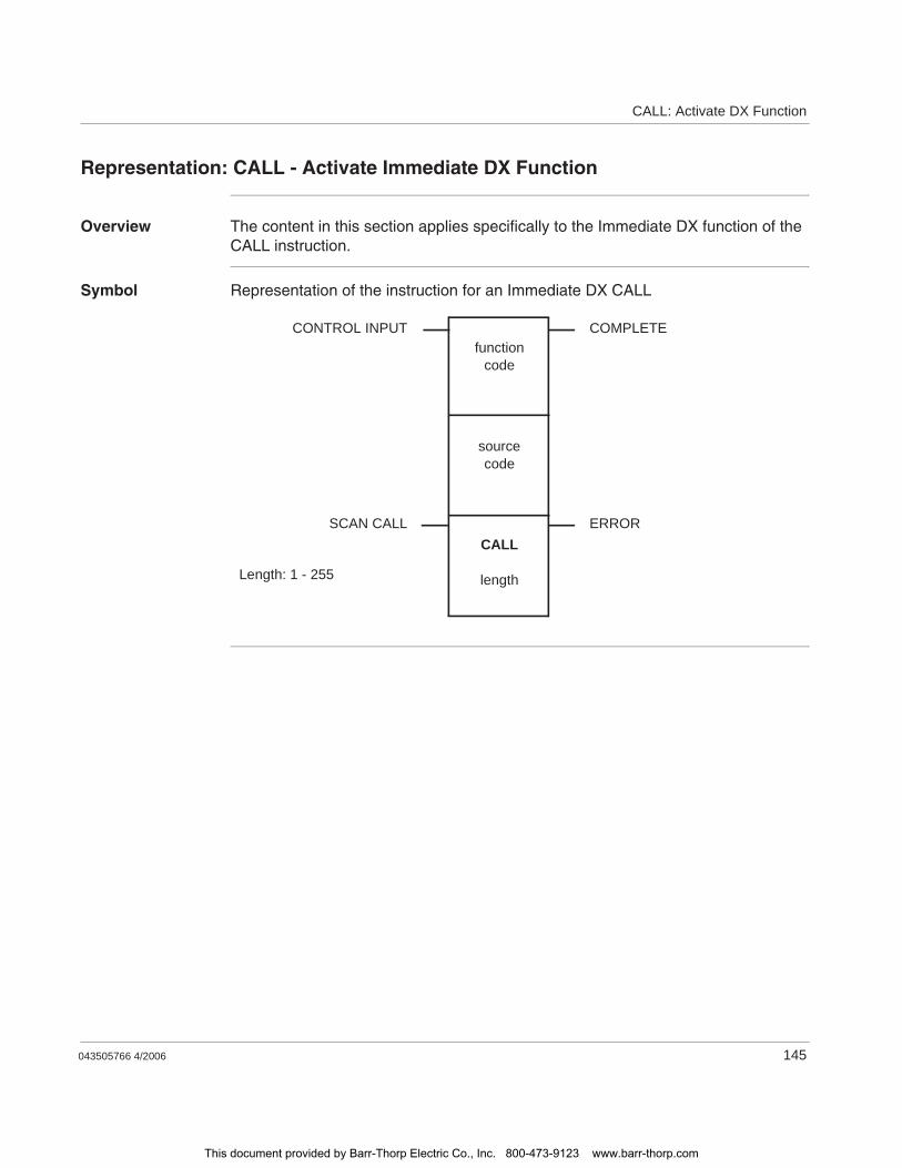
CALL: Activate DX Function
043505766 4/2006 145
Representation: CALL - Activate Immediate DX Function
Overview The content in this section applies specifically to the Immediate DX function of the CALL instruction.
Symbol Representation of the instruction for an Immediate DX CALL
CONTROL INPUT COMPLETE
ERROR
functioncode
sourcecode
CALL
lengthLength: 1 - 255
SCAN CALL
This document provided by Barr-Thorp Electric Co., Inc. 800-473-9123 www.barr-thorp.com
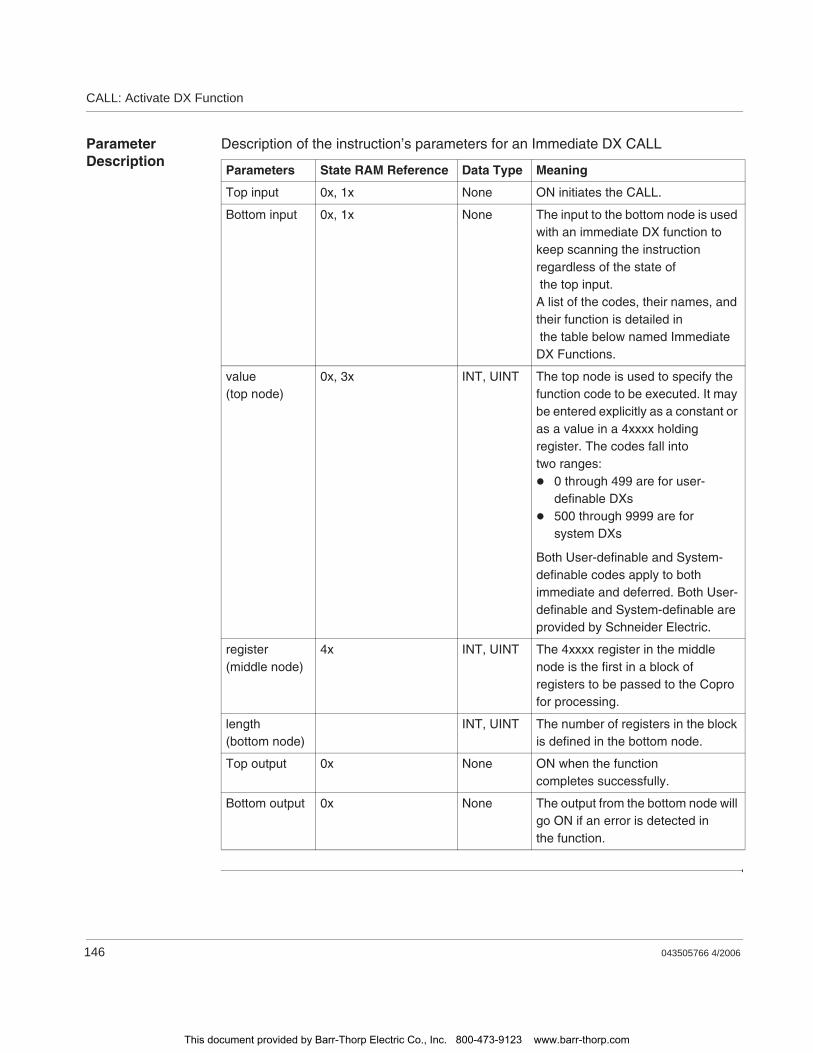
CALL: Activate DX Function
146 043505766 4/2006
Parameter Description
Description of the instruction’s parameters for an Immediate DX CALL
Parameters State RAM Reference Data Type Meaning
Top input 0x, 1x None ON initiates the CALL.
Bottom input 0x, 1x None The input to the bottom node is used with an immediate DX function to keep scanning the instruction regardless of the state of the top input.A list of the codes, their names, and their function is detailed in the table below named Immediate DX Functions.
value(top node)
0x, 3x INT, UINT The top node is used to specify the function code to be executed. It may be entered explicitly as a constant or as a value in a 4xxxx holding register. The codes fall into two ranges:
0 through 499 are for user-definable DXs500 through 9999 are forsystem DXs
Both User-definable and System-definable codes apply to both immediate and deferred. Both User-definable and System-definable are provided by Schneider Electric.
register(middle node)
4x INT, UINT The 4xxxx register in the middle node is the first in a block of registers to be passed to the Copro for processing.
length(bottom node)
INT, UINT The number of registers in the block is defined in the bottom node.
Top output 0x None ON when the function completes successfully.
Bottom output 0x None The output from the bottom node will go ON if an error is detected in the function.
This document provided by Barr-Thorp Electric Co., Inc. 800-473-9123 www.barr-thorp.com
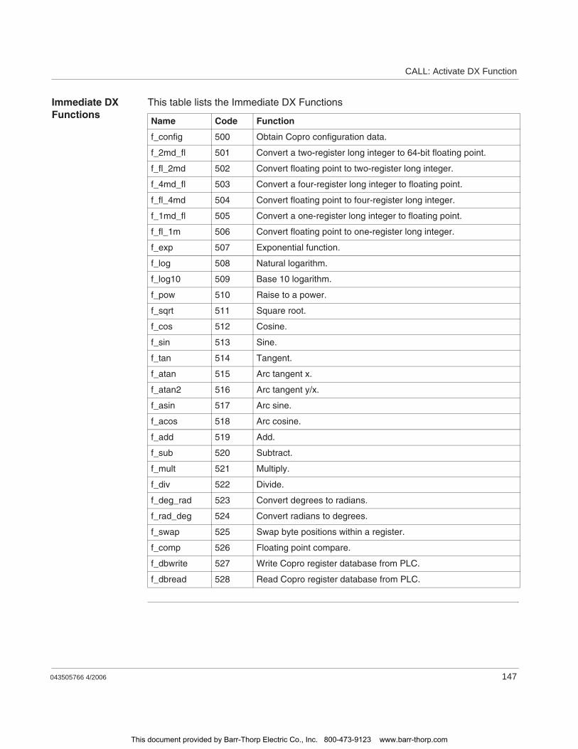
CALL: Activate DX Function
043505766 4/2006 147
Immediate DX Functions
This table lists the Immediate DX Functions
Name Code Function
f_config 500 Obtain Copro configuration data.
f_2md_fl 501 Convert a two-register long integer to 64-bit floating point.
f_fl_2md 502 Convert floating point to two-register long integer.
f_4md_fl 503 Convert a four-register long integer to floating point.
f_fl_4md 504 Convert floating point to four-register long integer.
f_1md_fl 505 Convert a one-register long integer to floating point.
f_fl_1m 506 Convert floating point to one-register long integer.
f_exp 507 Exponential function.
f_log 508 Natural logarithm.
f_log10 509 Base 10 logarithm.
f_pow 510 Raise to a power.
f_sqrt 511 Square root.
f_cos 512 Cosine.
f_sin 513 Sine.
f_tan 514 Tangent.
f_atan 515 Arc tangent x.
f_atan2 516 Arc tangent y/x.
f_asin 517 Arc sine.
f_acos 518 Arc cosine.
f_add 519 Add.
f_sub 520 Subtract.
f_mult 521 Multiply.
f_div 522 Divide.
f_deg_rad 523 Convert degrees to radians.
f_rad_deg 524 Convert radians to degrees.
f_swap 525 Swap byte positions within a register.
f_comp 526 Floating point compare.
f_dbwrite 527 Write Copro register database from PLC.
f_dbread 528 Read Copro register database from PLC.
This document provided by Barr-Thorp Electric Co., Inc. 800-473-9123 www.barr-thorp.com
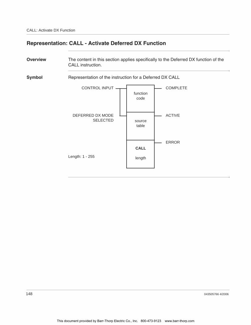
CALL: Activate DX Function
148 043505766 4/2006
Representation: CALL - Activate Deferred DX Function
Overview The content in this section applies specifically to the Deferred DX function of the CALL instruction.
Symbol Representation of the instruction for a Deferred DX CALL
CONTROL INPUT COMPLETE
ACTIVE
ERROR
functioncode
sourcetable
CALL
lengthLength: 1 - 255
DEFERRED DX MODESELECTED
This document provided by Barr-Thorp Electric Co., Inc. 800-473-9123 www.barr-thorp.com
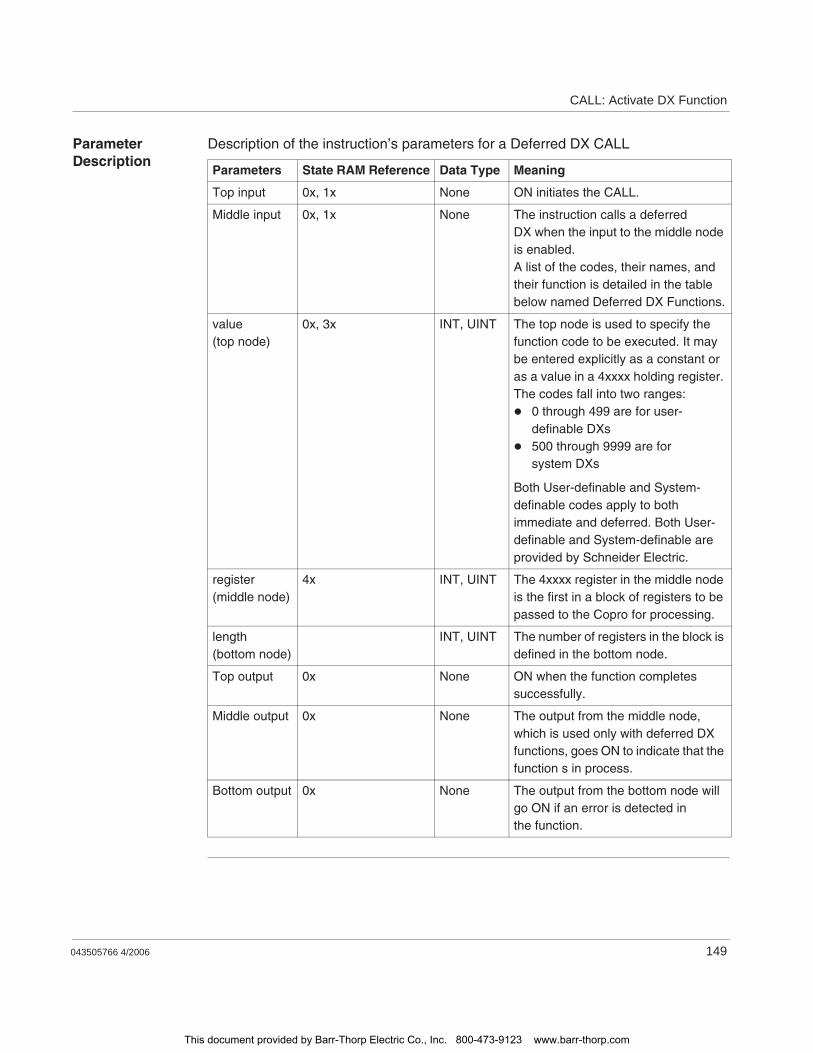
CALL: Activate DX Function
043505766 4/2006 149
Parameter Description
Description of the instruction’s parameters for a Deferred DX CALL
Parameters State RAM Reference Data Type Meaning
Top input 0x, 1x None ON initiates the CALL.
Middle input 0x, 1x None The instruction calls a deferred DX when the input to the middle node is enabled.A list of the codes, their names, and their function is detailed in the table below named Deferred DX Functions.
value(top node)
0x, 3x INT, UINT The top node is used to specify the function code to be executed. It may be entered explicitly as a constant or as a value in a 4xxxx holding register. The codes fall into two ranges:
0 through 499 are for user-definable DXs500 through 9999 are for system DXs
Both User-definable and System-definable codes apply to both immediate and deferred. Both User-definable and System-definable are provided by Schneider Electric.
register(middle node)
4x INT, UINT The 4xxxx register in the middle node is the first in a block of registers to be passed to the Copro for processing.
length(bottom node)
INT, UINT The number of registers in the block is defined in the bottom node.
Top output 0x None ON when the function completes successfully.
Middle output 0x None The output from the middle node, which is used only with deferred DX functions, goes ON to indicate that the function s in process.
Bottom output 0x None The output from the bottom node will go ON if an error is detected in the function.
This document provided by Barr-Thorp Electric Co., Inc. 800-473-9123 www.barr-thorp.com
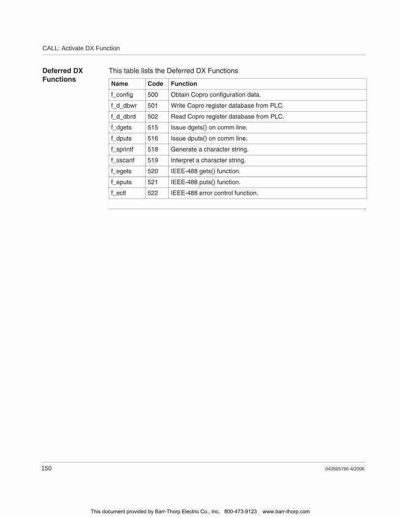
CALL: Activate DX Function
150 043505766 4/2006
Deferred DX Functions
This table lists the Deferred DX Functions
Name Code Function
f_config 500 Obtain Copro configuration data.
f_d_dbwr 501 Write Copro register database from PLC.
f_d_dbrd 502 Read Copro register database from PLC.
f_dgets 515 Issue dgets() on comm line.
f_dputs 516 Issue dputs() on comm line.
f_sprintf 518 Generate a character string.
f_sscanf 519 Interpret a character string.
f_egets 520 IEEE-488 gets() function.
f_eputs 521 IEEE-488 puts() function.
f_ectl 522 IEEE-488 error control function.
This document provided by Barr-Thorp Electric Co., Inc. 800-473-9123 www.barr-thorp.com
043505766 4/2006 151
23CANT - Interpret Coils, Contacts, Timers, Counters, and the SUB Block
At A Glance
Introduction This chapter describes the instruction CANT.
What's in this Chapter?
This chapter contains the following topics:
Topic Page
Short Description: CANT - Interpret Coils, Contacts, Timers, Counters, and the SUB Block
152
Representation: CANT - Interpret Coils, Contacts, Timers, Counters, and the SUB Block
153
Parameter Description: CANT - Interpret Coils, Contacts, Timers, Counters, and the SUB Block
154
This document provided by Barr-Thorp Electric Co., Inc. 800-473-9123 www.barr-thorp.com
CANT - Interpret Coils, Contacts, Timers, Counters, and the SUB Block
152 043505766 4/2006
Short Description: CANT - Interpret Coils, Contacts, Timers, Counters, and the SUB Block
Function Description
This DX Loadable Function Block, upon initializing a triggering contact, analyzes your ladder logic to extract the specific column and the corresponding contact id's where power flow has stopped. The CANT block contains 20 registers. A MSTR block is used to export data from the CANT's 20 registers to a PC running the "Action Monitor" program.
The CANT block is specifically used to interpret coils, contacts, timers, counters, and the SUB block. You may not use any other types of ladder logic instructions in a network. Otherwise, you receive incorrect results. If, however, you must use one of the other ladder logic instructions you may place them in a separate network linked to a coil that is referenced to the network containing the CANT block.
Note: Only 24-bit logic Quantum and 984 PLCs support the DX Loadable Function Block. 16-bit controllers will not work with this particular block.
This document provided by Barr-Thorp Electric Co., Inc. 800-473-9123 www.barr-thorp.com
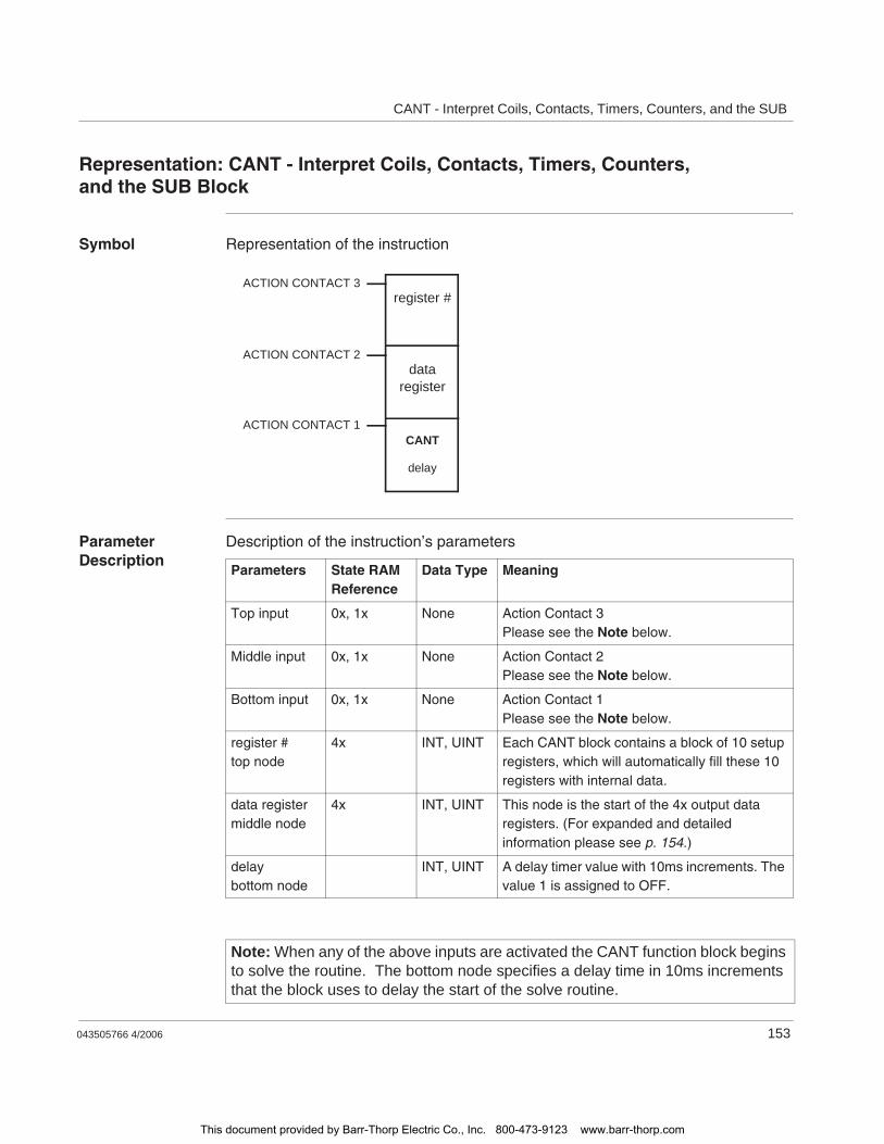
CANT - Interpret Coils, Contacts, Timers, Counters, and the SUB
043505766 4/2006 153
Representation: CANT - Interpret Coils, Contacts, Timers, Counters, and the SUB Block
Symbol Representation of the instruction
Parameter Description
Description of the instruction’s parameters
ACTION CONTACT 3
ACTION CONTACT 2
ACTION CONTACT 1
register #
dataregister
CANT
delay
Parameters State RAM Reference
Data Type Meaning
Top input 0x, 1x None Action Contact 3Please see the Note below.
Middle input 0x, 1x None Action Contact 2Please see the Note below.
Bottom input 0x, 1x None Action Contact 1Please see the Note below.
register #top node
4x INT, UINT Each CANT block contains a block of 10 setup registers, which will automatically fill these 10 registers with internal data.
data registermiddle node
4x INT, UINT This node is the start of the 4x output data registers. (For expanded and detailed information please see p. 154.)
delaybottom node
INT, UINT A delay timer value with 10ms increments. The value 1 is assigned to OFF.
Note: When any of the above inputs are activated the CANT function block begins to solve the routine. The bottom node specifies a delay time in 10ms increments that the block uses to delay the start of the solve routine.
This document provided by Barr-Thorp Electric Co., Inc. 800-473-9123 www.barr-thorp.com
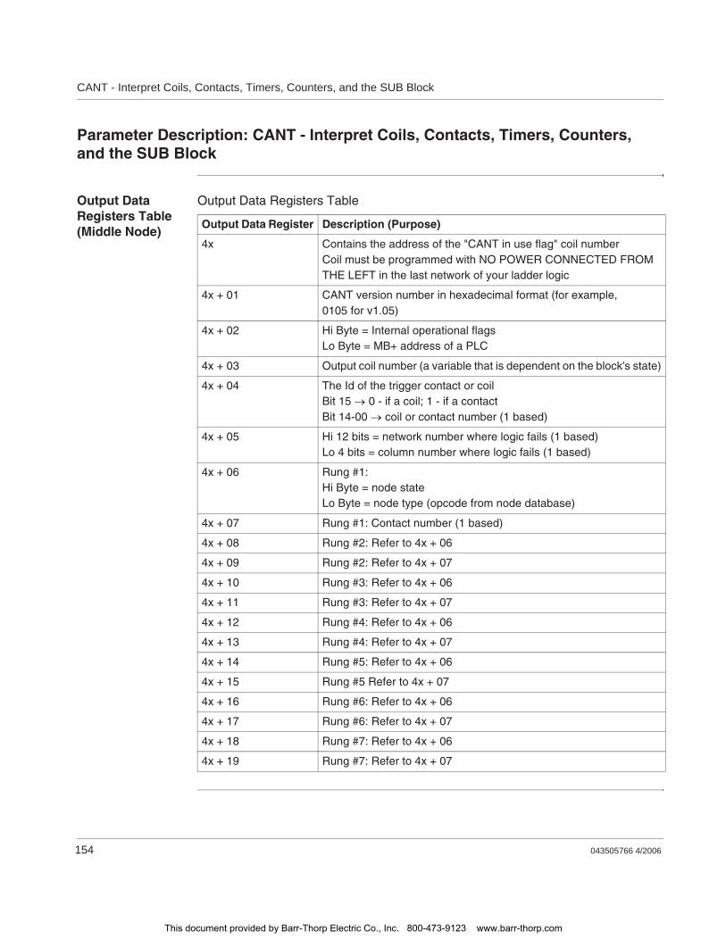
CANT - Interpret Coils, Contacts, Timers, Counters, and the SUB Block
154 043505766 4/2006
Parameter Description: CANT - Interpret Coils, Contacts, Timers, Counters, and the SUB Block
Output Data Registers Table (Middle Node)
Output Data Registers Table
Output Data Register Description (Purpose)
4x Contains the address of the "CANT in use flag" coil numberCoil must be programmed with NO POWER CONNECTED FROM THE LEFT in the last network of your ladder logic
4x + 01 CANT version number in hexadecimal format (for example, 0105 for v1.05)
4x + 02 Hi Byte = Internal operational flagsLo Byte = MB+ address of a PLC
4x + 03 Output coil number (a variable that is dependent on the block's state)
4x + 04 The Id of the trigger contact or coilBit 15 0 - if a coil; 1 - if a contactBit 14-00 coil or contact number (1 based)
4x + 05 Hi 12 bits = network number where logic fails (1 based)Lo 4 bits = column number where logic fails (1 based)
4x + 06 Rung #1:Hi Byte = node stateLo Byte = node type (opcode from node database)
4x + 07 Rung #1: Contact number (1 based)
4x + 08 Rung #2: Refer to 4x + 06
4x + 09 Rung #2: Refer to 4x + 07
4x + 10 Rung #3: Refer to 4x + 06
4x + 11 Rung #3: Refer to 4x + 07
4x + 12 Rung #4: Refer to 4x + 06
4x + 13 Rung #4: Refer to 4x + 07
4x + 14 Rung #5: Refer to 4x + 06
4x + 15 Rung #5 Refer to 4x + 07
4x + 16 Rung #6: Refer to 4x + 06
4x + 17 Rung #6: Refer to 4x + 07
4x + 18 Rung #7: Refer to 4x + 06
4x + 19 Rung #7: Refer to 4x + 07
This document provided by Barr-Thorp Electric Co., Inc. 800-473-9123 www.barr-thorp.com
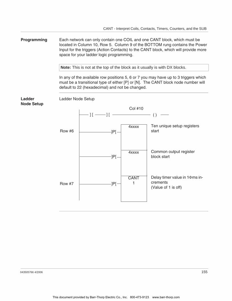
CANT - Interpret Coils, Contacts, Timers, Counters, and the SUB
043505766 4/2006 155
Programming Each network can only contain one COIL and one CANT block, which must be located in Column 10, Row 5. Column 9 of the BOTTOM rung contains the Power Input for the triggers (Action Contacts) to the CANT block, which will provide more space for your ladder logic programming.
In any of the available row positions 5, 6 or 7 you may have up to 3 triggers which must be a transitional type of either [P] or [N]. The CANT block node number will default to 22 (hexadecimal) and not be changed.
Ladder Node Setup
Ladder Node Setup
Note: This is not at the top of the block as it usually is with DX blocks.
CANT1
4xxxx
4xxxx]P[
Ten unique setup registers start
Delay timer value in 1 ms in-crements(Value of 1 is off)
]P[
Common output register block start]P[
] [ ] [ ( )
Col #10
Row #6
Row #7
This document provided by Barr-Thorp Electric Co., Inc. 800-473-9123 www.barr-thorp.com
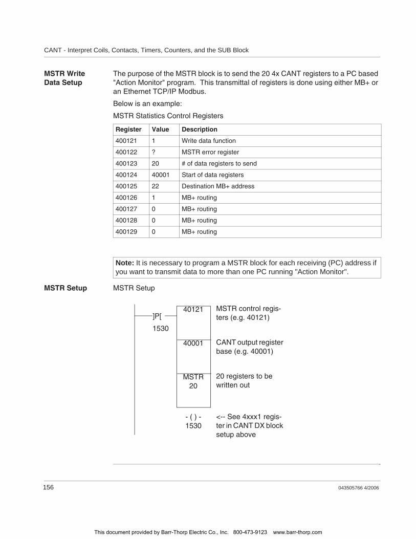
CANT - Interpret Coils, Contacts, Timers, Counters, and the SUB Block
156 043505766 4/2006
MSTR Write Data Setup
The purpose of the MSTR block is to send the 20 4x CANT registers to a PC based "Action Monitor" program. This transmittal of registers is done using either MB+ or an Ethernet TCP/IP Modbus.
Below is an example:
MSTR Statistics Control Registers
MSTR Setup MSTR Setup
Register Value Description
400121 1 Write data function
400122 ? MSTR error register
400123 20 # of data registers to send
400124 40001 Start of data registers
400125 22 Destination MB+ address
400126 1 MB+ routing
400127 0 MB+ routing
400128 0 MB+ routing
400129 0 MB+ routing
Note: It is necessary to program a MSTR block for each receiving (PC) address if you want to transmit data to more than one PC running "Action Monitor".
MSTR20
40001
40121]P[
MSTR control regis-ters (e.g. 40121)
20 registers to be written out
CANT output register base (e.g. 40001)
1530
- ( ) -1530
<-- See 4xxx1 regis-ter in CANT DX block setup above
This document provided by Barr-Thorp Electric Co., Inc. 800-473-9123 www.barr-thorp.com

043505766 4/2006 157
24CHS: Configure Hot Standby
At a Glance
Introduction This chapter describes the instruction CHS.
What's in this Chapter?
This chapter contains the following topics:
Topic Page
Short Description 158
Representation: CHS - Configure Hot Standby 159
Detailed Description 160
This document provided by Barr-Thorp Electric Co., Inc. 800-473-9123 www.barr-thorp.com

CHS: Configure Hot Standby
158 043505766 4/2006
Short Description
Function Description
The logic in the CHS loadable is the engine that drives the Hot Standby capability in a Quantum PLC system. Unlike the HSBY instruction, the use of the CHS instruction in the ladder logic program is optional. However, the loadable software itself must be installed in the Quantum PLC in order for a Hot Standby system to be implemented.
Note: This instruction is only available if you have unpacked and installed the DX Loadables. For further information, see p. 101."
This document provided by Barr-Thorp Electric Co., Inc. 800-473-9123 www.barr-thorp.com
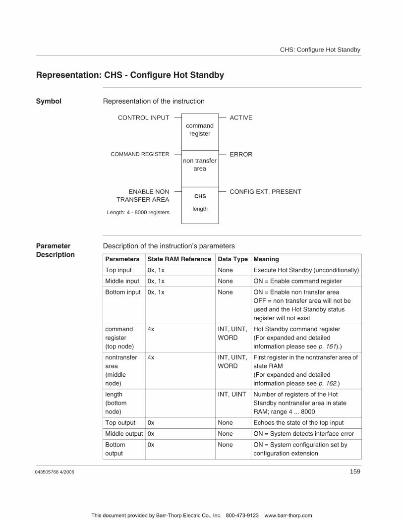
CHS: Configure Hot Standby
043505766 4/2006 159
Representation: CHS - Configure Hot Standby
Symbol Representation of the instruction
Parameter Description
Description of the instruction’s parameters
CHS
length
non transferarea
commandregister
CONTROL INPUT ACTIVE
CONFIG EXT. PRESENTENABLE NONTRANSFER AREA
ERRORCOMMAND REGISTER
Length: 4 - 8000 registers
Parameters State RAM Reference Data Type Meaning
Top input 0x, 1x None Execute Hot Standby (unconditionally)
Middle input 0x, 1x None ON = Enable command register
Bottom input 0x, 1x None ON = Enable non transfer areaOFF = non transfer area will not be used and the Hot Standby status register will not exist
command register(top node)
4x INT, UINT, WORD
Hot Standby command register(For expanded and detailed information please see p. 161).)
nontransfer area(middle node)
4x INT, UINT, WORD
First register in the nontransfer area of state RAM(For expanded and detailed information please see p. 162.)
length(bottom node)
INT, UINT Number of registers of the Hot Standby nontransfer area in state RAM; range 4 ... 8000
Top output 0x None Echoes the state of the top input
Middle output 0x None ON = System detects interface error
Bottom output
0x None ON = System configuration set by configuration extension
This document provided by Barr-Thorp Electric Co., Inc. 800-473-9123 www.barr-thorp.com
CHS: Configure Hot Standby
160 043505766 4/2006
Detailed Description
Hot Standby System Configuration via the CHS Instruction
Program the CHS instruction in network 1, segment 1 of your ladder logic program and unconditionally connect the top input to the power rail via a horizontal short (as the HSBY instruction is programmed in a 984 Hot Standby system).
This method is particularly useful if you are porting Hot Standby code from a 984 application to a Quantum application. The structure of the CHS instruction is almost exactly the same as the HSBY instruction. You simply remove the HSBY instruction from the 984 ladder logic and replace it with a CHS instruction in the Quantum logic.
If you are using the CHS instruction in ladder logic, the only difference between it and the HSBY instruction is the use of the bottom output. This output senses whether or not method 2 has been used. If the Hot Standby configuration extension screens have been used to define the Hot Standby configuration, the configuration parameters in the screens will override any different parameters defined by the CHS instruction at system startup.
For detailes discussion of the issues related to the configuration extension capabilities of a Quantum Hot Standby system, refer to the Modicon Quantum Hot Standby System Planning and Installation Guide.
Parameter Description Execute Hot Standby (Top Input)
When the CHS instruction is inserted in ladder logic to control the Hot Standby configuration parameters, its top input must be connected directly to the power rail by a horizontal short. No control logic, such as contacts, should be placed between the rail and the input to the top node.
Erratic behavior in the Hot Standby systemAlthough it is legal to enable and disable the nontransfer area while the Hot Standby system is running, we strongly discourage this practice. It can lead to erratic behavior in the Hot Standby system.
Failure to follow this instruction can result in death, serious injury, or equipment damage.
WARNING
This document provided by Barr-Thorp Electric Co., Inc. 800-473-9123 www.barr-thorp.com
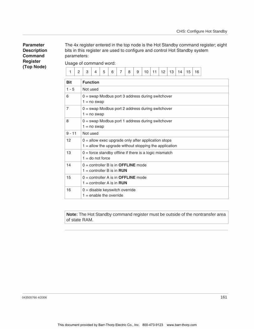
CHS: Configure Hot Standby
043505766 4/2006 161
Parameter Description Command Register (Top Node)
The 4x register entered in the top node is the Hot Standby command register; eight bits in this register are used to configure and control Hot Standby system parameters:
Usage of command word:
Bit Function
1 - 5 Not used
6 0 = swap Modbus port 3 address during switchover1 = no swap
7 0 = swap Modbus port 2 address during switchover1 = no swap
8 0 = swap Modbus port 1 address during switchover1 = no swap
9 - 11 Not used
12 0 = allow exec upgrade only after application stops1 = allow the upgrade without stopping the application
13 0 = force standby offline if there is a logic mismatch1 = do not force
14 0 = controller B is in OFFLINE mode1 = controller B is in RUN
15 0 = controller A is in OFFLINE mode1 = controller A is in RUN
16 0 = disable keyswitch override1 = enable the override
Note: The Hot Standby command register must be outside of the nontransfer area of state RAM.
1 2 3 4 5 6 7 8 9 10 11 12 13 14 15 16
This document provided by Barr-Thorp Electric Co., Inc. 800-473-9123 www.barr-thorp.com

CHS: Configure Hot Standby
162 043505766 4/2006
Parameter Description Nontransfer Area (Middle Node)
The 4x register entered in the middle node is the first register in the nontransfer area of state RAM. The nontransfer area must contain at least four registers, the first three of which have a predefined usage:
The content of the remaining registers is application-specific; the length is defined in the parameter "length" (bottom node).
The 4x registers in the nontransfer area are never transferred from the primary to the standby PLC during the logic scans. One reason for scheduling additional registers in the nontransfer area is to reduce the impact of state RAM transfer on the total system scan time.
CHS Status Register
Usage of status word:
Register Content
Displayed and first implied Reverse transfer registers for passing information from the standby to the primary PLC
Second implied CHS status register
Bit Function
1 1 = the top output is ON (indicating Hot Standby system is active)
2 1 = the middle output is ON (indicating an error condition)
3 - 10 Not used
11 0 = PLC switch is set to A1 = PLC switch is set to B
12 0 = PLC logic is matched1 = there is a logic mismatch
13 - 14 The 2 bit value is:0 1 if the other PLC is in OFFLINE mode1 0 if other PLC is running in primary mode1 1 if other PLC is running in standby mode
15 - 16 The 2 bit value is:0 1 if this PLC is in OFFLINE mode1 0 if this PLC is running in primary mode1 1 if this PLC is running in standby mode
1 2 3 4 5 6 7 8 9 10 11 12 13 14 15 16
This document provided by Barr-Thorp Electric Co., Inc. 800-473-9123 www.barr-thorp.com
043505766 4/2006 163
25CKSM: Check Sum
At a Glance
Introduction This chapter describes the instruction CKSM.
What's in this Chapter?
This chapter contains the following topics:
Topic Page
Short Description 164
Representation: CKSM - Checksum 165
Parameter Description 166
This document provided by Barr-Thorp Electric Co., Inc. 800-473-9123 www.barr-thorp.com

CKSM: Check Sum
164 043505766 4/2006
Short Description
Function Description
Several PLCs that do not support Modbus Plus come with a standard checksum (CKSM) instruction. CKSM has the same opcode as the MSTR instruction and is not provided in executive firmware for PLCs that support Modbus Plus.
This document provided by Barr-Thorp Electric Co., Inc. 800-473-9123 www.barr-thorp.com
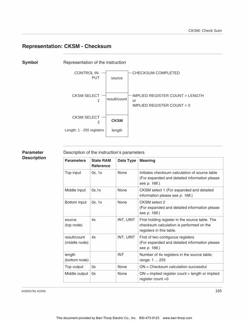
CKSM: Check Sum
043505766 4/2006 165
Representation: CKSM - Checksum
Symbol Representation of the instruction
Parameter Description
Description of the instruction’s parameters
CKSM
length
result/count
sourceCONTROL IN-
PUTCHECKSUM COMPLETED
CKSM SELECT2
Length: 1 - 255 registers
CKSM SELECT1
IMPLIED REGISTER COUNT > LENGTHorIMPLIED REGISTER COUNT = 0
Parameters State RAM Reference
Data Type Meaning
Top input 0x, 1x None Initiates checksum calculation of source table (For expanded and detailed information please see p. 166.)
Middle input 0x,1x None CKSM select 1 (For expanded and detailed information please see p. 166.)
Bottom input 0x, 1x None CKSM select 2(For expanded and detailed information please see p. 166.)
source(top node)
4x INT, UINT First holding register in the source table. The checksum calculation is performed on the registers in this table.
result/count(middle node)
4x INT, UINT First of two contiguous registers(For expanded and detailed information please see p. 166.)
length(bottom node)
INT Number of 4x registers in the source table; range: 1 ... 255
Top output 0x None ON = Checksum calculation successful
Middle output 0x None ON = implied register count > length or implied register count =0
This document provided by Barr-Thorp Electric Co., Inc. 800-473-9123 www.barr-thorp.com
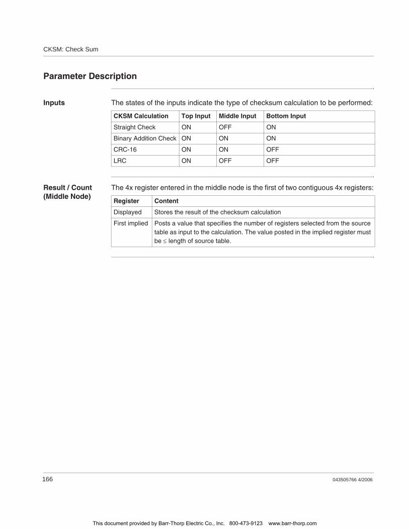
CKSM: Check Sum
166 043505766 4/2006
Parameter Description
Inputs The states of the inputs indicate the type of checksum calculation to be performed:
Result / Count (Middle Node)
The 4x register entered in the middle node is the first of two contiguous 4x registers:
CKSM Calculation Top Input Middle Input Bottom Input
Straight Check ON OFF ON
Binary Addition Check ON ON ON
CRC-16 ON ON OFF
LRC ON OFF OFF
Register Content
Displayed Stores the result of the checksum calculation
First implied Posts a value that specifies the number of registers selected from the source table as input to the calculation. The value posted in the implied register must be length of source table.
This document provided by Barr-Thorp Electric Co., Inc. 800-473-9123 www.barr-thorp.com
043505766 4/2006 167
26CMPR: Compare Register
At a Glance
Introduction This chapter describes the instruction CMPR.
What's in this Chapter?
This chapter contains the following topics:
Topic Page
Short Description 168
Representation: CMPR - Logical Compare 169
Parameter Description 170
This document provided by Barr-Thorp Electric Co., Inc. 800-473-9123 www.barr-thorp.com

CMPR: Compare Register
168 043505766 4/2006
Short Description
Function Description
The CMPR instruction compares the bit pattern in matrix a against the bit pattern in matrix b for miscompares. In a single scan, the two matrices are compared bit position by bit position until a miscompare is found or the end of the matrices is reached (without miscompares).
This document provided by Barr-Thorp Electric Co., Inc. 800-473-9123 www.barr-thorp.com

CMPR: Compare Register
043505766 4/2006 169
Representation: CMPR - Logical Compare
Symbol Representation of the instruction
Parameter Description
Description of the instruction’s parameters
CMPR
length
pointer register(matrix b)
matrix a
CONTROL INPUT ACTIVE
STATE OF MISCOMPARE
Length: 1 to 100 registers(16 to 1600 bits)
MISCOMPARERESET POINTER
First register ordiscrete addressof matrix
Parameters State RAM Reference Data Type Meaning
Top input 0x, 1x None ON = initiates compare operation
Middle input 0x, 1x None OFF = restart at last miscompareON = restart at the beginning
matrix a(top node)
0x, 1x, 3x, 4x ANY_BIT First reference in matrix a, one of the two matrices to be compared
pointer register(middle node)
4x WORD Pointer to matrix b: the first register in matrix b is the next contiguous 4x register following the pointer register
length(bottom node)
INT, UINT Matrix length; range: 1 ... 100
Top output 0x None Echoes state of the top input
Middle output 0x None ON = miscompare detected
Bottom output 0x None ON = miscompared bit in matrix a is 1OFF = miscompared bit in matrix a is 0
This document provided by Barr-Thorp Electric Co., Inc. 800-473-9123 www.barr-thorp.com
CMPR: Compare Register
170 043505766 4/2006
Parameter Description
Pointer Register (Middle Node)
The pointer register entered in the middle node must be a 4x holding register. It is the pointer to matrix b, the other matrix to be compared. The first register in matrix b is the next contiguous 4x register following the pointer register.
The value stored inside the pointer register increments with each bit position in the two matrices that is being compared. As bit position 1 in matrix a and matrix b is compared, the pointer register contains a value of 1; as bit position 2 in the matrices are compared, the pointer value increments to 2; etc.
When the outputs signal a miscompare, you can check the accumulated count in the pointer register to determine the bit position in the matrices of the miscompare.
Matrix Length (Bottom Node)
The integer value entered in the bottom node specifies a length of the two matrices, i.e. the number of registers or 16-bit words in each matrix. (Matrix a and matrix b have the same length.) The matrix length can range from 1 ... 100, i.e. a length of 2 indicates that matrix a and matrix b contain 32 bits.
This document provided by Barr-Thorp Electric Co., Inc. 800-473-9123 www.barr-thorp.com
043505766 4/2006 171
27Coils
At A Glance
Introduction This chapter describes the instruction element Coils.
What's in this Chapter?
This chapter contains the following topics:
Topic Page
Short Description: Coils 172
General Usage Guidelines: Coils 173
This document provided by Barr-Thorp Electric Co., Inc. 800-473-9123 www.barr-thorp.com
Coils
172 043505766 4/2006
Short Description: Coils
Function Description
A coil is a discrete output that is turned ON and OFF by power flow in the logic program. A single coil is tied to a 0xxxx reference in the PLC’s state RAM. Because output values are updated in state RAM by the PLC, a coil may be used internally in the logic program or externally via the I/O map to a discrete output unit in the control system. When a coil is ON, it either passes power to a discrete output circuit or changes the state of an internal relay contact in state RAM.
Coil Types There are two types of coils:Normal coil -( )-A normal or non-retentive or normal coil looses state when power to controller is lost.When power is removed from a PLC, a normal coil will be turned OFF. Once power is restored, the coil will always be in the OFF state on the first logic scan.Memory-retentive or latched coil -(M)- or -(L)-A memory-retentive or latched coil does NOT loose state when power to controller is lost. If a memory-retentive (or latched) coil is ON at the time a PLC loses power, the coil will come back up in an ON state when power is restored. The coil will maintain that ON state for the first logic scan, and then the logic program will take control.
Coils are referenced as 0xxxx. They may be disabled and forced ON or OFF. Disabling a coil stops the user programmed logic from changing the state of the coil.
Note: Disabled Coils used as destinations in DX function blocks may have their state overwritten by the function.
This document provided by Barr-Thorp Electric Co., Inc. 800-473-9123 www.barr-thorp.com
Coils
043505766 4/2006 173
General Usage Guidelines: Coils
Overview Once a 0x reference number has been assigned to a coil, it cannot be assigned to any other coils in the logic program.
An 0x reference number can be referenced to any number of relay contacts, which can then be controlled via the state of the coil with same reference number. Most panel software packages have a feature called tracing with which you can locate the positions in ladder logic of the contacts controlled by a coil. Refer to your software user manual for more details.
Enable/Disable Capabilities for Discrete Values
Via panel software, you may disable a logic coil or a discrete input in your logic program.
A disable condition will cause the following:Input field device to have no control over its assigned 1x logicLogic to have no control over the disable 9x value
Memory protection in the PLC must be OFF before you disable or enable a coil or a discrete input.
Forcing Discretes ON and OFF
Most panel software also provides FORCE ON and FORCE OFF capabilities. When a coil or discrete input is disabled, you can change its state from OFF to ON with FORCE ON, and from ON to OFF with FORCE OFF.
When a coil or discrete input is enabled, it cannot be forced ON or OFF.
Note: There is an important exception that you need to be aware of when disabling coils: Data transfer functions allow coils in their destination nodes to recognize the current ON/OFF state of ALL coils, whether those coils are disabled or not, and this recognition causes the logic to respond accordingly—maybe producing unexpected and undesirable effects.If you are expecting a disabled coil to remain disabled in the DX function, your application may experience unexpected and undesirable effects.
This document provided by Barr-Thorp Electric Co., Inc. 800-473-9123 www.barr-thorp.com

Coils
174 043505766 4/2006
This document provided by Barr-Thorp Electric Co., Inc. 800-473-9123 www.barr-thorp.com
043505766 4/2006 175
28COMM - ASCII Communications Function
At A Glance
Introduction This chapter describes the COMM instruction.
What's in this Chapter?
This chapter contains the following topics:
Topic Page
Short Description: COMM - ASCII Communications Block 176
Representation: COMM - ASCII Communications Function 177
This document provided by Barr-Thorp Electric Co., Inc. 800-473-9123 www.barr-thorp.com
COMM - ASCII Communications Function
176 043505766 4/2006
Short Description: COMM - ASCII Communications Block
Function Description
The ASCII Communications Function (COMM) block is used to transmit/receive ASCII data (in the form of a single ASCII character, 1 to 4 integers or 1 to 4 hexadecimal numbers) to or from the simple ASCII port. The COMM instruction gives you the ability to read and write canned messages to/from ASCII character input/output devices via one of the built-in communication ports on a Micro PLC or, if the PLC is a parent, via a comm port on one of the child PLCs on the expansion link.
Note: Available only on the Micro 311, 411, 512, and 612 controllers.
This document provided by Barr-Thorp Electric Co., Inc. 800-473-9123 www.barr-thorp.com
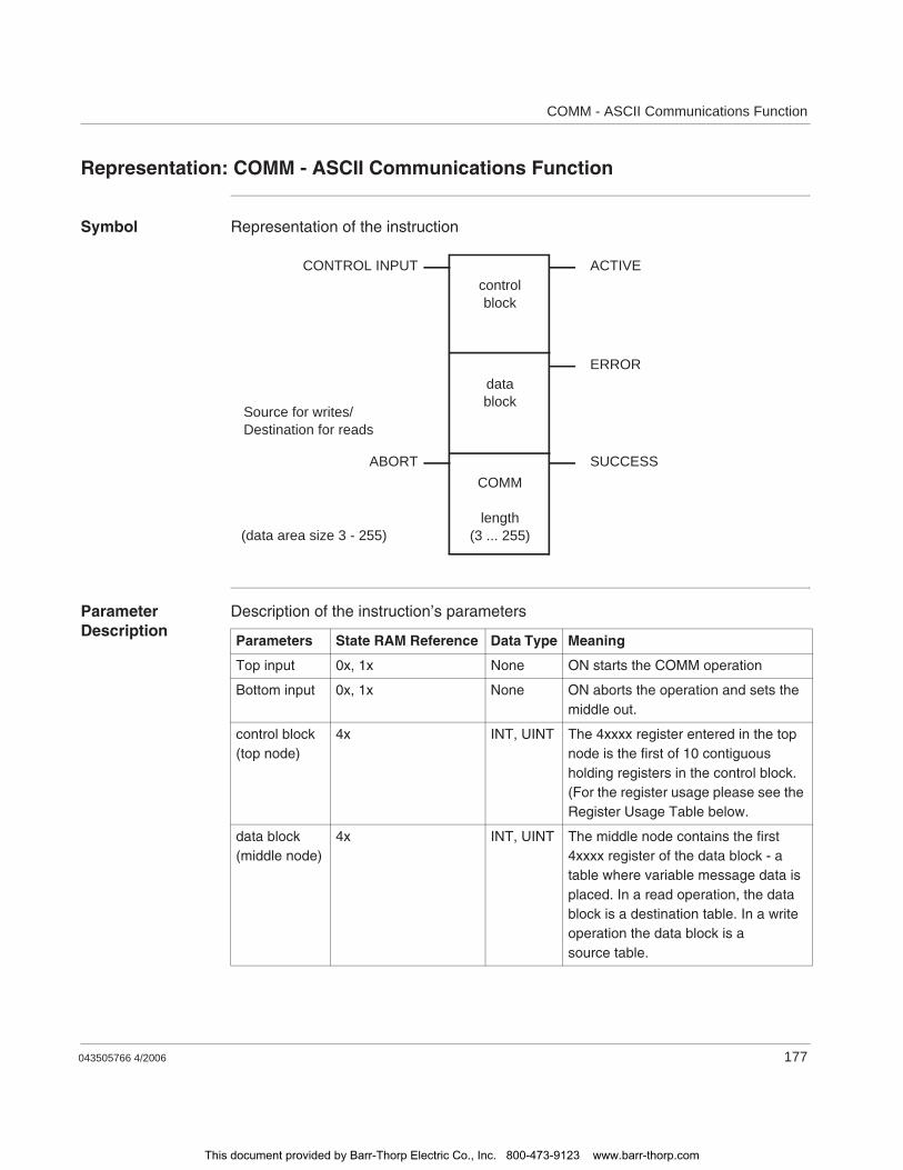
COMM - ASCII Communications Function
043505766 4/2006 177
Representation: COMM - ASCII Communications Function
Symbol Representation of the instruction
Parameter Description
Description of the instruction’s parameters
CONTROL INPUT
ABORT
ACTIVE
ERROR
SUCCESS
controlblock
datablock
COMM
length(3 ... 255)(data area size 3 - 255)
Source for writes/Destination for reads
Parameters State RAM Reference Data Type Meaning
Top input 0x, 1x None ON starts the COMM operation
Bottom input 0x, 1x None ON aborts the operation and sets the middle out.
control block(top node)
4x INT, UINT The 4xxxx register entered in the top node is the first of 10 contiguous holding registers in the control block.(For the register usage please see the Register Usage Table below.
data block(middle node)
4x INT, UINT The middle node contains the first 4xxxx register of the data block - a table where variable message data is placed. In a read operation, the data block is a destination table. In a write operation the data block is a source table.
This document provided by Barr-Thorp Electric Co., Inc. 800-473-9123 www.barr-thorp.com
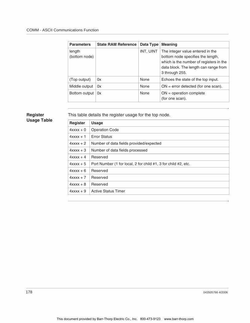
COMM - ASCII Communications Function
178 043505766 4/2006
Register Usage Table
This table details the register usage for the top node.
length(bottom node)
INT, UINT The integer value entered in the bottom node specifies the length, which is the number of registers in the data block. The length can range from 3 through 255.
(Top output) 0x None Echoes the state of the top input.
Middle output 0x None ON = error detected (for one scan).
Bottom output 0x None ON = operation complete (for one scan).
Parameters State RAM Reference Data Type Meaning
Register Usage
4xxxx + 0 Operation Code
4xxxx + 1 Error Status
4xxxx + 2 Number of data fields provided/expected
4xxxx + 3 Number of data fields processed
4xxxx + 4 Reserved
4xxxx + 5 Port Number (1 for local, 2 for child #1, 3 for child #2, etc.
4xxxx + 6 Reserved
4xxxx + 7 Reserved
4xxxx + 8 Reserved
4xxxx + 9 Active Status Timer
This document provided by Barr-Thorp Electric Co., Inc. 800-473-9123 www.barr-thorp.com

043505766 4/2006 179
29COMP: Complement a Matrix
At a Glance
Introduction This chapter describes the instruction COMP.
What's in this Chapter?
This chapter contains the following topics:
Topic Page
Short Description 180
Representation: COMP - Logical Compliment 181
Parameter Description 183
This document provided by Barr-Thorp Electric Co., Inc. 800-473-9123 www.barr-thorp.com

COMP: Complement a Matrix
180 043505766 4/2006
Short Description
Function Description
The COMP instruction complements the bit pattern, i.e. changes all 0’s to 1’s and all 1’s to 0’s, of a source matrix, then copies the complemented bit pattern into a destination matrix. The entire COMP operation is accomplished in one scan.
Overriding of any disabled coils in the destination matrix without enabling them.COMP will override any disabled coils in the destination matrix without enabling them. This can cause injury if a coil has been disabled for repair or maintenance because the coil’s state can be changed by the COMP operation.
Failure to follow this instruction can result in death, serious injury, or equipment damage.
WARNING
This document provided by Barr-Thorp Electric Co., Inc. 800-473-9123 www.barr-thorp.com
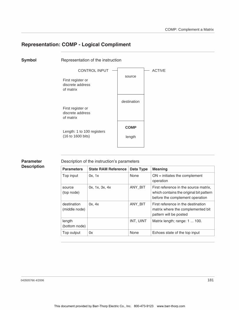
COMP: Complement a Matrix
043505766 4/2006 181
Representation: COMP - Logical Compliment
Symbol Representation of the instruction
Parameter Description
Description of the instruction’s parameters
COMP
length
destination
sourceCONTROL INPUT ACTIVE
Length: 1 to 100 registers(16 to 1600 bits)
First register ordiscrete addressof matrix
First register ordiscrete addressof matrix
Parameters State RAM Reference Data Type Meaning
Top input 0x, 1x None ON = initiates the complement operation
source(top node)
0x, 1x, 3x, 4x ANY_BIT First reference in the source matrix, which contains the original bit pattern before the complement operation
destination(middle node)
0x, 4x ANY_BIT First reference in the destination matrix where the complemented bit pattern will be posted
length(bottom node)
INT, UINT Matrix length; range: 1 ... 100.
Top output 0x None Echoes state of the top input
This document provided by Barr-Thorp Electric Co., Inc. 800-473-9123 www.barr-thorp.com
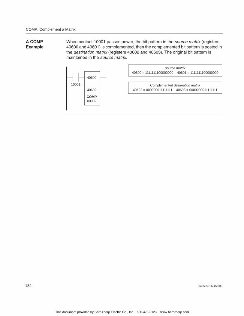
COMP: Complement a Matrix
182 043505766 4/2006
A COMP Example
When contact 10001 passes power, the bit pattern in the source matrix (registers 40600 and 40601) is complemented, then the complemented bit pattern is posted in the destination matrix (registers 40602 and 40603). The original bit pattern is maintained in the source matrix.
source matrix40600 = 1111111100000000 40601 = 1111111100000000
Complemented destination matrix40602 = 000000011111111 40603 = 0000000011111111
40600
40602
00002
10001
COMP
This document provided by Barr-Thorp Electric Co., Inc. 800-473-9123 www.barr-thorp.com

COMP: Complement a Matrix
043505766 4/2006 183
Parameter Description
Matrix Length (Bottom Node)
The integer value entered in the bottom node specifies a matrix length, i.e. the number of registers or 16-bit words in the matrices. Matrix length can range from 1 ... 100. A length of 2 indicates that 32 bits in each matrix will be complemented.
This document provided by Barr-Thorp Electric Co., Inc. 800-473-9123 www.barr-thorp.com

COMP: Complement a Matrix
184 043505766 4/2006
This document provided by Barr-Thorp Electric Co., Inc. 800-473-9123 www.barr-thorp.com
043505766 4/2006 185
30Contacts
At A Glance
Introduction This chapter describes the instruction element Contacts.
What's in this Chapter?
This chapter contains the following topics:
Topic Page
Short Description: Contacts 186
Representation: Contacts 187
This document provided by Barr-Thorp Electric Co., Inc. 800-473-9123 www.barr-thorp.com

Contacts
186 043505766 4/2006
Short Description: Contacts
Function Description
Contacts are used to pass or inhibit power flow in a ladder logic program.
This document provided by Barr-Thorp Electric Co., Inc. 800-473-9123 www.barr-thorp.com
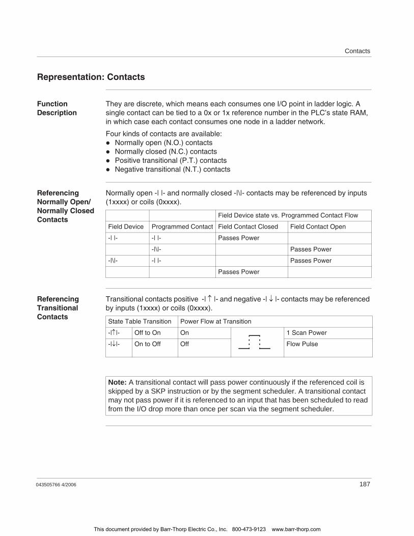
Contacts
043505766 4/2006 187
Representation: Contacts
Function Description
They are discrete, which means each consumes one I/O point in ladder logic. A single contact can be tied to a 0x or 1x reference number in the PLC’s state RAM, in which case each contact consumes one node in a ladder network.
Four kinds of contacts are available:Normally open (N.O.) contactsNormally closed (N.C.) contactsPositive transitional (P.T.) contactsNegative transitional (N.T.) contacts
Referencing Normally Open/Normally Closed Contacts
Normally open -| |- and normally closed -|\|- contacts may be referenced by inputs (1xxxx) or coils (0xxxx).
Referencing Transitional Contacts
Transitional contacts positive -| |- and negative -| |- contacts may be referenced by inputs (1xxxx) or coils (0xxxx).
Field Device state vs. Programmed Contact Flow
Field Device Programmed Contact Field Contact Closed Field Contact Open
-| |- -| |- Passes Power
-|\|- Passes Power
-|\|- -| |- Passes Power
Passes Power
State Table Transition Power Flow at Transition
-| |- Off to On On 1 Scan Power
-| |- On to Off Off Flow Pulse
Note: A transitional contact will pass power continuously if the referenced coil is skipped by a SKP instruction or by the segment scheduler. A transitional contact may not pass power if it is referenced to an input that has been scheduled to read from the I/O drop more than once per scan via the segment scheduler.
This document provided by Barr-Thorp Electric Co., Inc. 800-473-9123 www.barr-thorp.com

Contacts
188 043505766 4/2006
This document provided by Barr-Thorp Electric Co., Inc. 800-473-9123 www.barr-thorp.com

043505766 4/2006 189
31CONV - Convert Data
At A Glance
Introduction This chapter describes the instruction CONV.
What's in this Chapter?
This chapter contains the following topics:
Topic Page
Short Description: CONV - Convert Data 190
Representation: CONV - Convert Data 191
This document provided by Barr-Thorp Electric Co., Inc. 800-473-9123 www.barr-thorp.com
CONV - Convert Data
190 043505766 4/2006
Short Description: CONV - Convert Data
Function The Convert block is a 484-replacement instruction, and it is one of four replacement instructions. The CONV block is used to convert
Discrete data to a holding registerHolding-register data to discrete data
The conversion can be either
Binary to binaryBCD to binary (discrete to register)Binary to BCD (register to discrete)
This block uses 12 bits in 12 bits out, but if the conversion is straight binary to binary, bits 11 and 12 are forced off.
In converting discretes to a holding register, the source is specified as a constant which implies a 1xxxx and the destination is specified as a constant which implies a 4xxxx (for example, 00049 implies 40049).
In converting a register to output discretes, the source is specified as a holding register (4xxxx) and the destination is specified as a constant which implies a 0xxxx. For example 00032 implies 12 coils with 00032.
Important: Care should be taken when converting register data to discretes as coils may inadvertently be activated.
Note: Available only on the 984-351 and 984-455 PLCs.
This document provided by Barr-Thorp Electric Co., Inc. 800-473-9123 www.barr-thorp.com
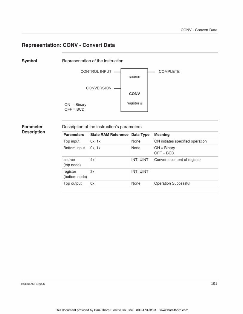
CONV - Convert Data
043505766 4/2006 191
Representation: CONV - Convert Data
Symbol Representation of the instruction
Parameter Description
Description of the instruction’s parameters
CONTROL INPUT
CONVERSION
COMPLETE
ON = BinaryOFF = BCD
source
CONV
register #
Parameters State RAM Reference Data Type Meaning
Top input 0x, 1x None ON initiates specified operation
Bottom input 0x, 1x None ON = BinaryOFF = BCD
source(top node)
4x INT, UINT Converts content of register
register(bottom node)
3x INT, UINT
Top output 0x None Operation Successful
This document provided by Barr-Thorp Electric Co., Inc. 800-473-9123 www.barr-thorp.com

CONV - Convert Data
192 043505766 4/2006
This document provided by Barr-Thorp Electric Co., Inc. 800-473-9123 www.barr-thorp.com
043505766 4/2006 193
32CTIF - Counter, Timer, and Interrupt Function
At A Glance
Introduction This chapter describes the CTIF instruction.
What's in this Chapter?
This chapter contains the following topics:
Topic Page
Short Description: CTIF - Counter, Timer, and Interrupt Function 194
Representation: CTIF - Counter, Timer, Interrupt Function 195
Parameter Description: CTIF - Register Usage Table (Top Node) 196
This document provided by Barr-Thorp Electric Co., Inc. 800-473-9123 www.barr-thorp.com
CTIF - Counter, Timer, and Interrupt Function
194 043505766 4/2006
Short Description: CTIF - Counter, Timer, and Interrupt Function
Function Description
The CTIF block is used by a parent PLC to access child functions over an I/O expansion bus. The Parent function block will complete in the same scan. If multiple blocks exist, the last one executed will be used.
The CTIF instruction is used with the Micro PLCs to set up the inputs for hard-wired interrupt and/or hard-wired counter/timer operations. This instruction always starts and finishes in the same scan. The CTIF instruction is a configuration/operation tool for Modicon Micro PLCs that contain hardware interrupts (all models except the 110CPU311 Models). The actual counter/timer and interrupts are in the PLC hardware, and the CTIF instruction is what is used to set up this hardware.
Note: The Counter, Timer, Interrupt function (CTIF) is only available on Micro 311, 411, 512, and 612 controllers.
This document provided by Barr-Thorp Electric Co., Inc. 800-473-9123 www.barr-thorp.com
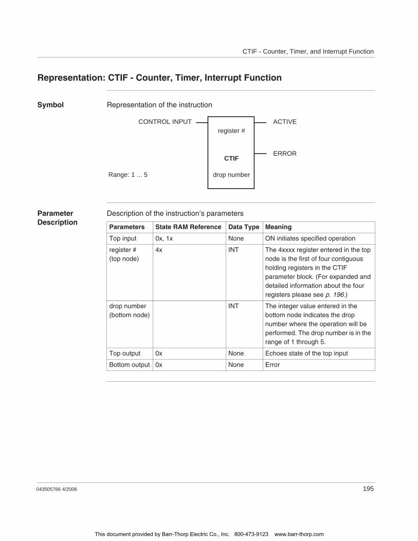
CTIF - Counter, Timer, and Interrupt Function
043505766 4/2006 195
Representation: CTIF - Counter, Timer, Interrupt Function
Symbol Representation of the instruction
Parameter Description
Description of the instruction’s parameters
CONTROL INPUT ACTIVE
Range: 1 ... 5
register #
CTIF
drop number
ERROR
Parameters State RAM Reference Data Type Meaning
Top input 0x, 1x None ON initiates specified operation
register #(top node)
4x INT The 4xxxx register entered in the top node is the first of four contiguous holding registers in the CTIF parameter block. (For expanded and detailed information about the four registers please see p. 196.)
drop number(bottom node)
INT The integer value entered in the bottom node indicates the drop number where the operation will be performed. The drop number is in the range of 1 through 5.
Top output 0x None Echoes state of the top input
Bottom output 0x None Error
This document provided by Barr-Thorp Electric Co., Inc. 800-473-9123 www.barr-thorp.com
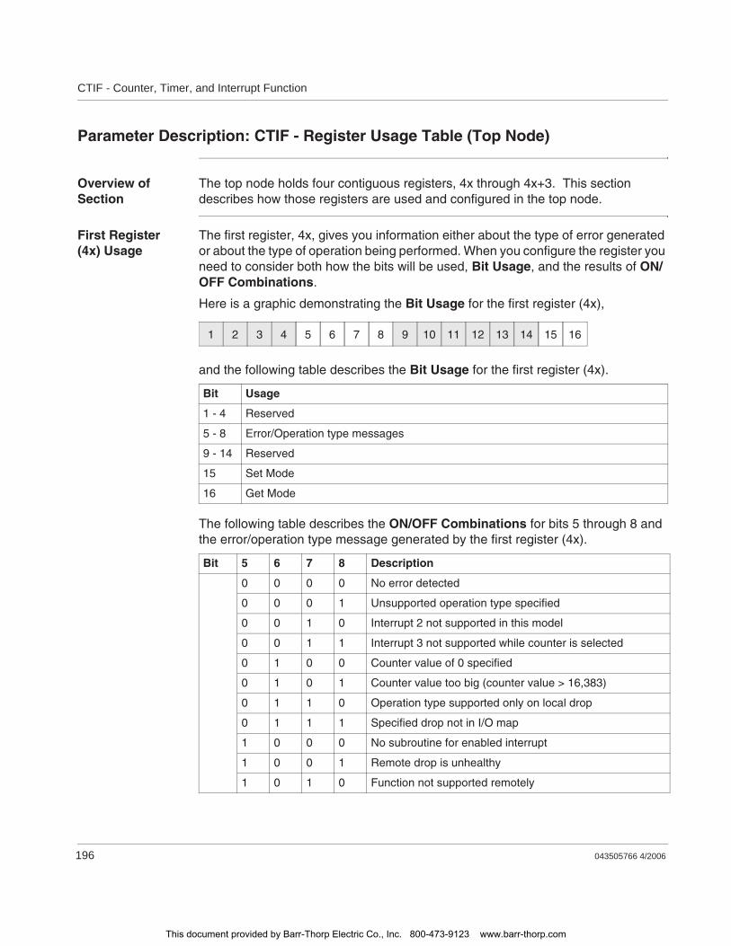
CTIF - Counter, Timer, and Interrupt Function
196 043505766 4/2006
Parameter Description: CTIF - Register Usage Table (Top Node)
Overview of Section
The top node holds four contiguous registers, 4x through 4x+3. This section describes how those registers are used and configured in the top node.
First Register (4x) Usage
The first register, 4x, gives you information either about the type of error generated or about the type of operation being performed. When you configure the register you need to consider both how the bits will be used, Bit Usage, and the results of ON/OFF Combinations.
Here is a graphic demonstrating the Bit Usage for the first register (4x),
and the following table describes the Bit Usage for the first register (4x).
The following table describes the ON/OFF Combinations for bits 5 through 8 and the error/operation type message generated by the first register (4x).
Bit Usage
1 - 4 Reserved
5 - 8 Error/Operation type messages
9 - 14 Reserved
15 Set Mode
16 Get Mode
Bit 5 6 7 8 Description
0 0 0 0 No error detected
0 0 0 1 Unsupported operation type specified
0 0 1 0 Interrupt 2 not supported in this model
0 0 1 1 Interrupt 3 not supported while counter is selected
0 1 0 0 Counter value of 0 specified
0 1 0 1 Counter value too big (counter value > 16,383)
0 1 1 0 Operation type supported only on local drop
0 1 1 1 Specified drop not in I/O map
1 0 0 0 No subroutine for enabled interrupt
1 0 0 1 Remote drop is unhealthy
1 0 1 0 Function not supported remotely
1 2 3 4 5 6 7 8 9 10 11 12 13 14 15 16
This document provided by Barr-Thorp Electric Co., Inc. 800-473-9123 www.barr-thorp.com
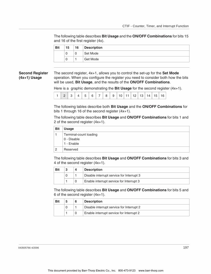
CTIF - Counter, Timer, and Interrupt Function
043505766 4/2006 197
The following table describes Bit Usage and the ON/OFF Combinations for bits 15 and 16 of the first register (4x).
Second Register (4x+1) Usage
The second register, 4x+1, allows you to control the set-up for the Set Mode operation. When you configure the register you need to consider both how the bits will be used, Bit Usage, and the results of the ON/OFF Combinations.
Here is a graphic demonstrating the Bit Usage for the second register (4x+1).
The following tables describe both Bit Usage and the ON/OFF Combinations for bits 1 through 16 of the second register (4x+1).
The following table describes Bit Usage and ON/OFF Combinations for bits 1 and 2 of the second register (4x+1).
The following table describes Bit Usage and ON/OFF Combinations for bits 3 and 4 of the second register (4x+1).
The following table describes Bit Usage and ON/OFF Combinations for bits 5 and 6 of the second register (4x+1).
Bit 15 16 Description
0 0 Set Mode
0 1 Get Mode
Bit Usage
1 Terminal-count loading0 - Disable1 - Enable
2 Reserved
Bit 3 4 Description
0 1 Disable interrupt service for Interrupt 3
1 0 Enable interrupt service for Interrupt 3
Bit 5 6 Description
0 1 Disable interrupt service for Interrupt 2
1 0 Enable interrupt service for Interrupt 2
1 2 3 4 5 6 7 8 9 10 11 12 13 14 15 16
This document provided by Barr-Thorp Electric Co., Inc. 800-473-9123 www.barr-thorp.com
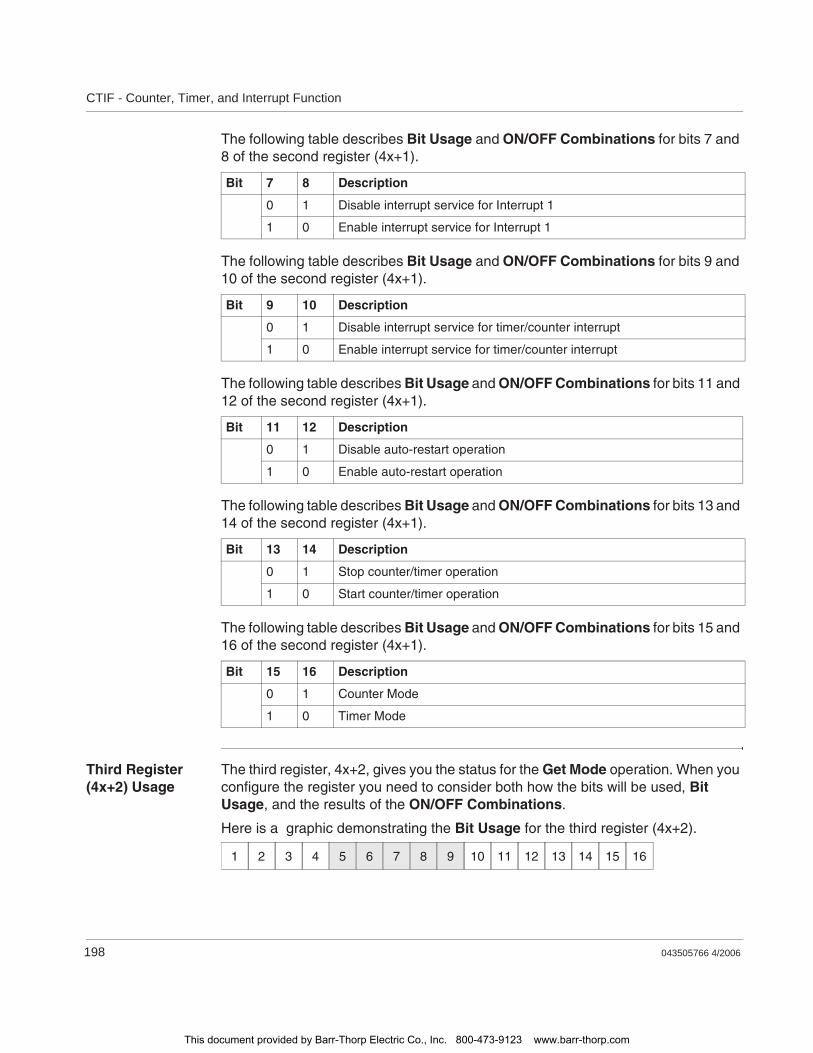
CTIF - Counter, Timer, and Interrupt Function
198 043505766 4/2006
The following table describes Bit Usage and ON/OFF Combinations for bits 7 and 8 of the second register (4x+1).
The following table describes Bit Usage and ON/OFF Combinations for bits 9 and 10 of the second register (4x+1).
The following table describes Bit Usage and ON/OFF Combinations for bits 11 and 12 of the second register (4x+1).
The following table describes Bit Usage and ON/OFF Combinations for bits 13 and 14 of the second register (4x+1).
The following table describes Bit Usage and ON/OFF Combinations for bits 15 and 16 of the second register (4x+1).
Third Register (4x+2) Usage
The third register, 4x+2, gives you the status for the Get Mode operation. When you configure the register you need to consider both how the bits will be used, Bit Usage, and the results of the ON/OFF Combinations.
Here is a graphic demonstrating the Bit Usage for the third register (4x+2).
Bit 7 8 Description
0 1 Disable interrupt service for Interrupt 1
1 0 Enable interrupt service for Interrupt 1
Bit 9 10 Description
0 1 Disable interrupt service for timer/counter interrupt
1 0 Enable interrupt service for timer/counter interrupt
Bit 11 12 Description
0 1 Disable auto-restart operation
1 0 Enable auto-restart operation
Bit 13 14 Description
0 1 Stop counter/timer operation
1 0 Start counter/timer operation
Bit 15 16 Description
0 1 Counter Mode
1 0 Timer Mode
1 2 3 4 5 6 7 8 9 10 11 12 13 14 15 16
This document provided by Barr-Thorp Electric Co., Inc. 800-473-9123 www.barr-thorp.com
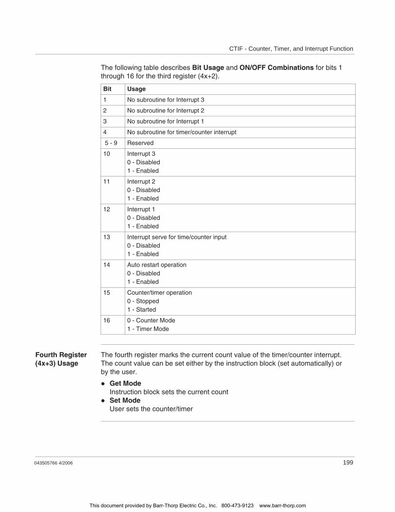
CTIF - Counter, Timer, and Interrupt Function
043505766 4/2006 199
The following table describes Bit Usage and ON/OFF Combinations for bits 1 through 16 for the third register (4x+2).
Fourth Register (4x+3) Usage
The fourth register marks the current count value of the timer/counter interrupt. The count value can be set either by the instruction block (set automatically) or by the user.
Get ModeInstruction block sets the current countSet ModeUser sets the counter/timer
Bit Usage
1 No subroutine for Interrupt 3
2 No subroutine for Interrupt 2
3 No subroutine for Interrupt 1
4 No subroutine for timer/counter interrupt
5 - 9 Reserved
10 Interrupt 30 - Disabled1 - Enabled
11 Interrupt 20 - Disabled1 - Enabled
12 Interrupt 10 - Disabled1 - Enabled
13 Interrupt serve for time/counter input0 - Disabled1 - Enabled
14 Auto restart operation0 - Disabled1 - Enabled
15 Counter/timer operation0 - Stopped1 - Started
16 0 - Counter Mode1 - Timer Mode
This document provided by Barr-Thorp Electric Co., Inc. 800-473-9123 www.barr-thorp.com

CTIF - Counter, Timer, and Interrupt Function
200 043505766 4/2006
This document provided by Barr-Thorp Electric Co., Inc. 800-473-9123 www.barr-thorp.com

043505766 4/2006 203
33DCTR: Down Counter
At a Glance
Introduction This chapter describes the instruction DCTR.
What's in this Chapter?
This chapter contains the following topics:
Topic Page
Short Description 204
Representation: DCTR - Down Counter 205
This document provided by Barr-Thorp Electric Co., Inc. 800-473-9123 www.barr-thorp.com

DCTR: Down Counter
204 043505766 4/2006
Short Description
Function Description
The DCTR instruction counts control input transitions from OFF to ON down from a counter preset value to zero.
This document provided by Barr-Thorp Electric Co., Inc. 800-473-9123 www.barr-thorp.com
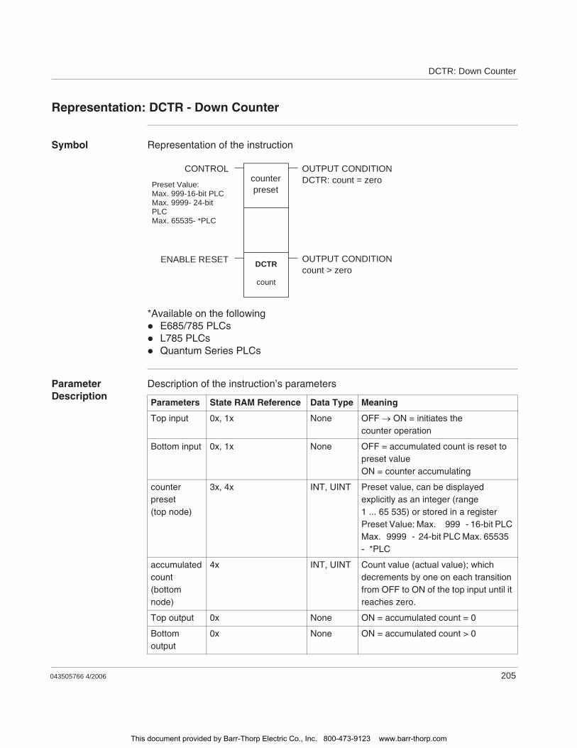
DCTR: Down Counter
043505766 4/2006 205
Representation: DCTR - Down Counter
Symbol Representation of the instruction
*Available on the followingE685/785 PLCsL785 PLCsQuantum Series PLCs
Parameter Description
Description of the instruction’s parameters
DCTR
count
counter preset
CONTROL OUTPUT CONDITIONDCTR: count = zero
ENABLE RESET OUTPUT CONDITIONcount > zero
Preset Value:Max. 999-16-bit PLCMax. 9999- 24-bit PLCMax. 65535- *PLC
Parameters State RAM Reference Data Type Meaning
Top input 0x, 1x None OFF ON = initiates the counter operation
Bottom input 0x, 1x None OFF = accumulated count is reset to preset valueON = counter accumulating
counter preset(top node)
3x, 4x INT, UINT Preset value, can be displayed explicitly as an integer (range 1 ... 65 535) or stored in a registerPreset Value: Max. 999 - 16-bit PLC Max. 9999 - 24-bit PLC Max. 65535 - *PLC
accumulated count(bottom node)
4x INT, UINT Count value (actual value); which decrements by one on each transition from OFF to ON of the top input until it reaches zero.
Top output 0x None ON = accumulated count = 0
Bottom output
0x None ON = accumulated count > 0
This document provided by Barr-Thorp Electric Co., Inc. 800-473-9123 www.barr-thorp.com

DCTR: Down Counter
206 043505766 4/2006
This document provided by Barr-Thorp Electric Co., Inc. 800-473-9123 www.barr-thorp.com
043505766 4/2006 207
34DIOH: Distributed I/O Health
At a Glance
Introduction This chapter describes the instruction DIOH.
What's in this Chapter?
This chapter contains the following topics:
Topic Page
Short Description 208
Representation: DIOH - Distributed I/O Health 209
Parameter Description 211
This document provided by Barr-Thorp Electric Co., Inc. 800-473-9123 www.barr-thorp.com

DIOH: Distributed I/O Health
208 043505766 4/2006
Short Description
Function Description
The DIOH instruction lets you retrieve health data from a specified group of drops on the distributed I/O network. It accesses the DIO health status table, where health data for modules in up to 189 distributed drops is stored.
This document provided by Barr-Thorp Electric Co., Inc. 800-473-9123 www.barr-thorp.com

DIOH: Distributed I/O Health
043505766 4/2006 209
Representation: DIOH - Distributed I/O Health
Symbol Representation of the instruction
DIOH
(1 ... 64)
destination
sourceCONTROL INPUT ACTIVE
ERRORNumber of Drops (1 - 64)
DIO Health Table
This document provided by Barr-Thorp Electric Co., Inc. 800-473-9123 www.barr-thorp.com
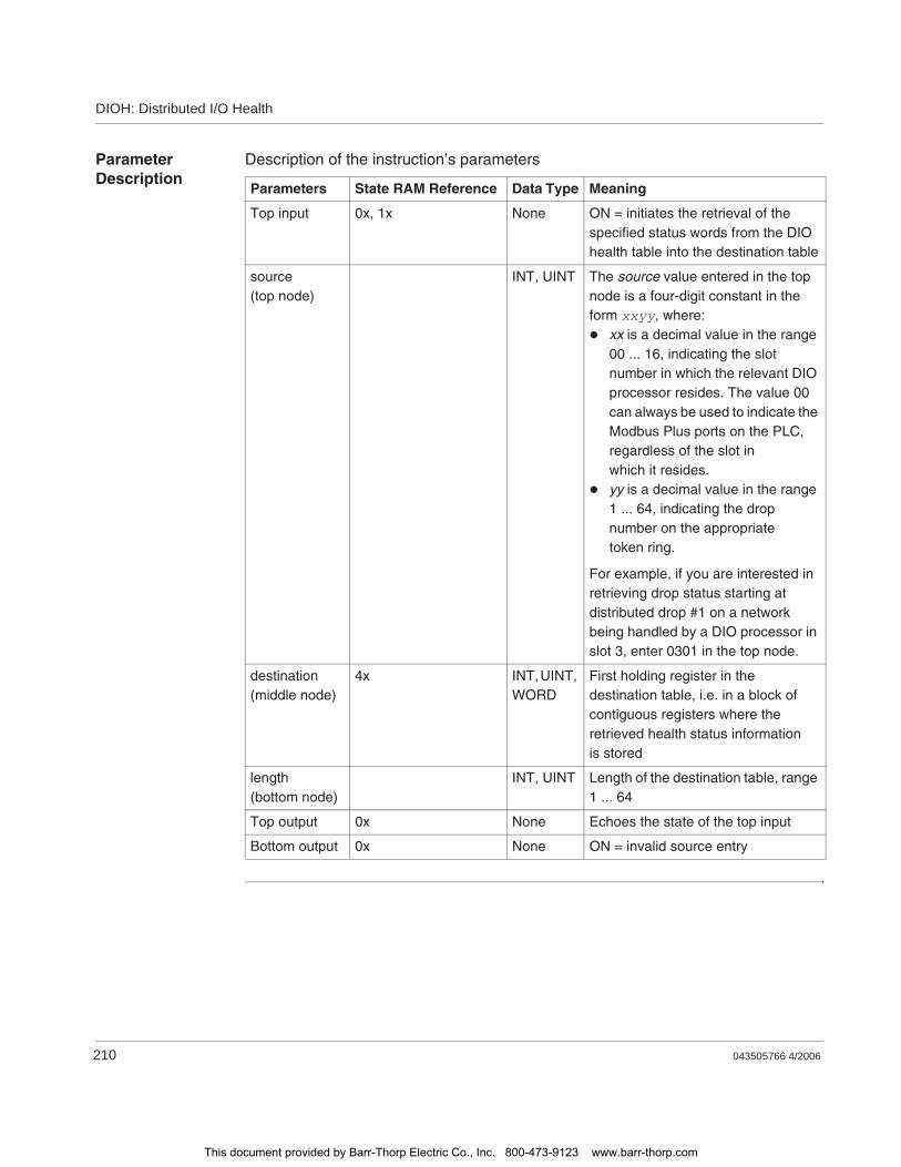
DIOH: Distributed I/O Health
210 043505766 4/2006
Parameter Description
Description of the instruction’s parameters
Parameters State RAM Reference Data Type Meaning
Top input 0x, 1x None ON = initiates the retrieval of the specified status words from the DIO health table into the destination table
source(top node)
INT, UINT The source value entered in the top node is a four-digit constant in the form xxyy, where:
xx is a decimal value in the range 00 ... 16, indicating the slot number in which the relevant DIO processor resides. The value 00 can always be used to indicate the Modbus Plus ports on the PLC, regardless of the slot in which it resides.yy is a decimal value in the range 1 ... 64, indicating the drop number on the appropriate token ring.
For example, if you are interested in retrieving drop status starting at distributed drop #1 on a network being handled by a DIO processor in slot 3, enter 0301 in the top node.
destination(middle node)
4x INT, UINT, WORD
First holding register in the destination table, i.e. in a block of contiguous registers where the retrieved health status information is stored
length(bottom node)
INT, UINT Length of the destination table, range 1 ... 64
Top output 0x None Echoes the state of the top input
Bottom output 0x None ON = invalid source entry
This document provided by Barr-Thorp Electric Co., Inc. 800-473-9123 www.barr-thorp.com

DIOH: Distributed I/O Health
043505766 4/2006 211
Parameter Description
Source Value (Top Node)
The source value entered in the top node is a four-digit constant in the form xxyy, where:
For example, if you are interested in retrieving drop status starting at distributed drop #1 on a network being handled by a DIO processor in slot 3, enter 0301 in thetop node.
Length of Destination Table (Bottom Node)
The integer value entered in the bottom node specifies the length, i.e. the number of 4x registers, in the destination table. The length is in the range 1 ... 64.
Digits Meaning
xx Decimal value in the range 00 ... 16, indicating the slot number in which the relevant DIO processor resides. The value 00 can always be used to indicate the Modbus Plus ports on the PLC, regardless of the slot in which it resides.
yy Decimal value in the range 1 ... 64, indicating the drop number on the appropriate token ring
Note: If you specify a length that excedes the number of drops available, the instruction will return status information only for the drops available. For example, if you specify the 63rd drop number (yy) in the top node register and then request a length of 5, the instruction will give you only two registers (the 63rd and 64th drop status words) in the destination table.
This document provided by Barr-Thorp Electric Co., Inc. 800-473-9123 www.barr-thorp.com

DIOH: Distributed I/O Health
212 043505766 4/2006
This document provided by Barr-Thorp Electric Co., Inc. 800-473-9123 www.barr-thorp.com
043505766 4/2006 213
35DISA - Disabled Discrete Monitor
At A Glance
Introduction This chapter describes the instruction DISA.
What's in this Chapter?
This chapter contains the following topics:
Topic Page
Short Description: DISA - Disabled Discrete Monitor 214
Representation: DISA - Disabled Discrete Monitor 215
This document provided by Barr-Thorp Electric Co., Inc. 800-473-9123 www.barr-thorp.com

DISA - Disabled Discrete Monitor
214 043505766 4/2006
Short Description: DISA - Disabled Discrete Monitor
Function The Disabled Discrete Monitor (DISA) is a loadable function, an instruction that monitors disabled coils and inputs. Therefore, DISA monitors the disabled states of all 0xxxx and 1xxxx addresses.
This document provided by Barr-Thorp Electric Co., Inc. 800-473-9123 www.barr-thorp.com
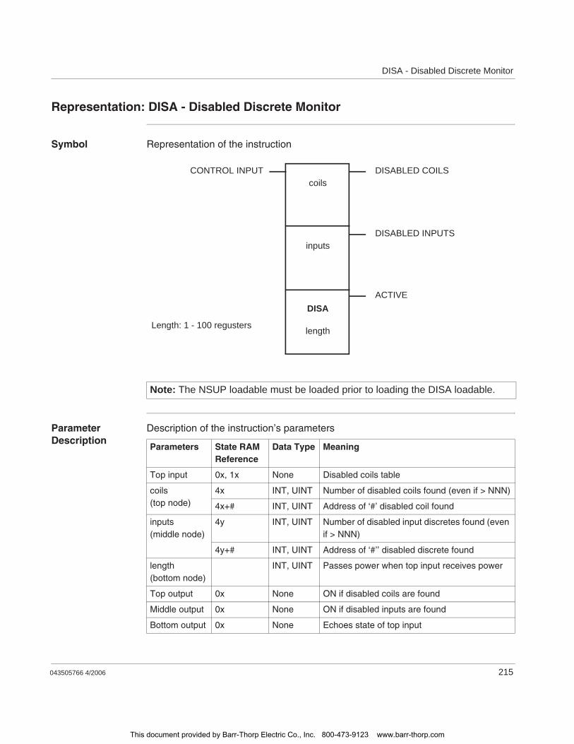
DISA - Disabled Discrete Monitor
043505766 4/2006 215
Representation: DISA - Disabled Discrete Monitor
Symbol Representation of the instruction
Parameter Description
Description of the instruction’s parameters
Note: The NSUP loadable must be loaded prior to loading the DISA loadable.
CONTROL INPUT DISABLED COILS
DISABLED INPUTS
ACTIVE
coils
inputs
DISA
lengthLength: 1 - 100 regusters
Parameters State RAM Reference
Data Type Meaning
Top input 0x, 1x None Disabled coils table
coils(top node)
4x INT, UINT Number of disabled coils found (even if > NNN)
4x+# INT, UINT Address of ‘#’ disabled coil found
inputs(middle node)
4y INT, UINT Number of disabled input discretes found (even if > NNN)
4y+# INT, UINT Address of ‘#’’ disabled discrete found
length(bottom node)
INT, UINT Passes power when top input receives power
Top output 0x None ON if disabled coils are found
Middle output 0x None ON if disabled inputs are found
Bottom output 0x None Echoes state of top input
This document provided by Barr-Thorp Electric Co., Inc. 800-473-9123 www.barr-thorp.com

DISA - Disabled Discrete Monitor
216 043505766 4/2006
This document provided by Barr-Thorp Electric Co., Inc. 800-473-9123 www.barr-thorp.com
043505766 4/2006 217
36DIV: Divide
At a Glance
Introduction This chapter describes the instruction DIV.
What's in this Chapter?
This chapter contains the following topics:
Topic Page
Short Description 218
Representation: DIV - Single Precision Division 219
Example 221
This document provided by Barr-Thorp Electric Co., Inc. 800-473-9123 www.barr-thorp.com

DIV: Divide
218 043505766 4/2006
Short Description
Function Description
The DIV instruction divides unsigned value 1 (its top node) by unsigned value 2 (its middle node) and posts the quotient and remainder in two contiguous holding registers in the bottom node.
This document provided by Barr-Thorp Electric Co., Inc. 800-473-9123 www.barr-thorp.com
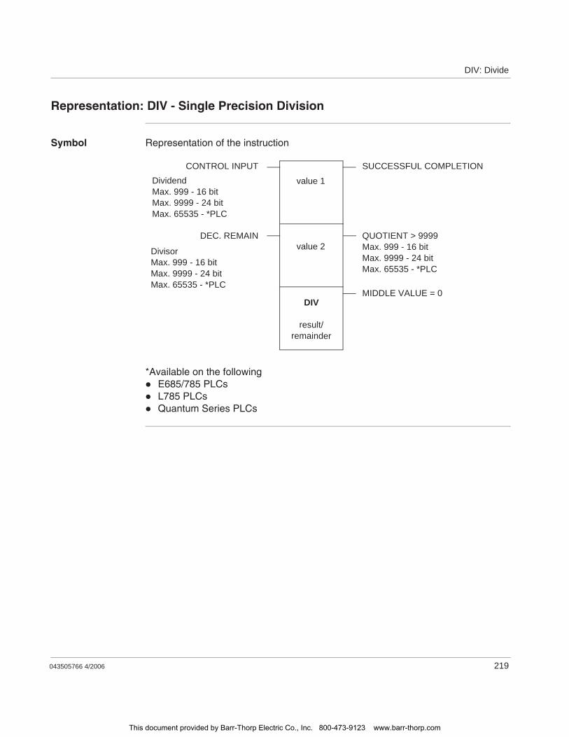
DIV: Divide
043505766 4/2006 219
Representation: DIV - Single Precision Division
Symbol Representation of the instruction
*Available on the followingE685/785 PLCsL785 PLCsQuantum Series PLCs
DIV
result/remainder
value 2
value 1
CONTROL INPUT SUCCESSFUL COMPLETION
MIDDLE VALUE = 0
QUOTIENT > 9999Max. 999 - 16 bitMax. 9999 - 24 bitMax. 65535 - *PLC
DEC. REMAIN
DivisorMax. 999 - 16 bitMax. 9999 - 24 bitMax. 65535 - *PLC
DividendMax. 999 - 16 bitMax. 9999 - 24 bitMax. 65535 - *PLC
This document provided by Barr-Thorp Electric Co., Inc. 800-473-9123 www.barr-thorp.com
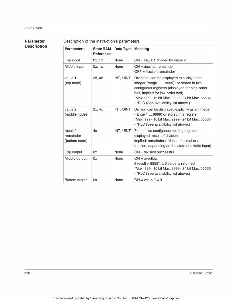
DIV: Divide
220 043505766 4/2006
Parameter Description
Description of the instruction’s parameters
Parameters State RAM Reference
Data Type Meaning
Top input 0x, 1x None ON = value 1 divided by value 2
Middle input 0x, 1x None ON = decimal remainderOFF = fraction remainder
value 1(top node)
3x, 4x INT, UINT Dividend, can be displayed explicitly as an integer (range 1 ... 9999)* or stored in two contiguous registers (displayed for high-order half, implied for low-order half)*Max. 999 - 16 bit Max. 9999 - 24 bit Max. 65535 - *PLC (See availability list above.)
value 2(middle node)
3x, 4x INT, UINT Divisor, can be displayed explicitly as an integer (range 1 ... 9999) or stored in a register*Max. 999 - 16 bit Max. 9999 - 24 bit Max. 65535 - *PLC (See availability list above.)
result /remainder(bottom node)
4x INT, UINT First of two contiguous holding registers: displayed: result of divisionimplied: remainder (either a decimal or a fraction, depending on the state of middle input)
Top output 0x None ON = division successful
Middle output 0x None ON = overflow:if result > 9999*, a 0 value is returned*Max. 999 - 16 bit Max. 9999 - 24 bit Max. 65535 - *PLC (See availability list above.)
Bottom output 0x None ON = value 2 = 0
This document provided by Barr-Thorp Electric Co., Inc. 800-473-9123 www.barr-thorp.com

DIV: Divide
043505766 4/2006 221
Example
Quotient of Instruction DIV
The state of the middle input indicates whether the remainder will be expressed as a decimal or as a fraction. For example, if value 1 = 8 and value 2 = 3, the decimal remainder (middle input ON) is 6666; the fractional remainder (middle input OFF) is 2.
This document provided by Barr-Thorp Electric Co., Inc. 800-473-9123 www.barr-thorp.com

DIV: Divide
222 043505766 4/2006
This document provided by Barr-Thorp Electric Co., Inc. 800-473-9123 www.barr-thorp.com
043505766 4/2006 223
37DLOG: Data Logging for PCMCIA Read/Write Support
At a Glance
Introduction This chapter describes the instruction DLOG.
What's in this Chapter?
This chapter contains the following topics:
Topic Page
Short Description 224
Representation: DLOG 225
Parameter Description 226
Run Time Error Handling 228
This document provided by Barr-Thorp Electric Co., Inc. 800-473-9123 www.barr-thorp.com

DLOG: Data Logging for PCMCIA Read/Write Support
224 043505766 4/2006
Short Description
Function Description
PCMCIA read and write support consists of a configuration extension to be implemented using a DLOG instruction. The DLOG instruction provides the facility for an application to copy data to a PCMCIA flash card, copy data from a PCMCIA flash card, erase individual memory blocks on a PCMCIA flash card, and to erase an entire PCMCIA flash card. The data format and the frequency of data storage are controlled by the application.
Note: This instruction is only available with the PLC family TSX Compact.
Note: The DLOG instruction will only operate with PCMCIA linear flash cards that use AMD flash devices.
This document provided by Barr-Thorp Electric Co., Inc. 800-473-9123 www.barr-thorp.com
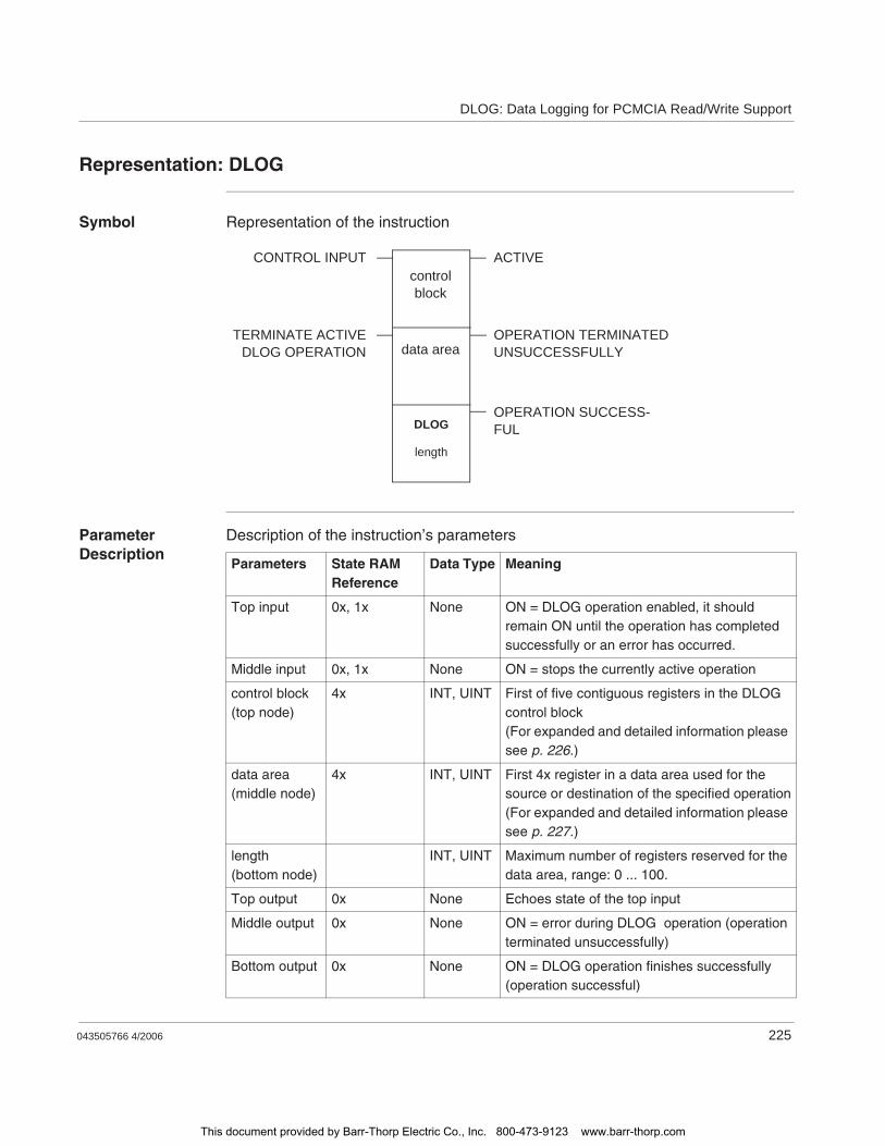
DLOG: Data Logging for PCMCIA Read/Write Support
043505766 4/2006 225
Representation: DLOG
Symbol Representation of the instruction
Parameter Description
Description of the instruction’s parameters
DLOG
length
data area
controlblock
CONTROL INPUT ACTIVE
OPERATION SUCCESS-FUL
OPERATION TERMINATEDUNSUCCESSFULLY
TERMINATE ACTIVEDLOG OPERATION
Parameters State RAM Reference
Data Type Meaning
Top input 0x, 1x None ON = DLOG operation enabled, it should remain ON until the operation has completed successfully or an error has occurred.
Middle input 0x, 1x None ON = stops the currently active operation
control block(top node)
4x INT, UINT First of five contiguous registers in the DLOG control block(For expanded and detailed information please see p. 226.)
data area(middle node)
4x INT, UINT First 4x register in a data area used for the source or destination of the specified operation(For expanded and detailed information please see p. 227.)
length(bottom node)
INT, UINT Maximum number of registers reserved for the data area, range: 0 ... 100.
Top output 0x None Echoes state of the top input
Middle output 0x None ON = error during DLOG operation (operation terminated unsuccessfully)
Bottom output 0x None ON = DLOG operation finishes successfully (operation successful)
This document provided by Barr-Thorp Electric Co., Inc. 800-473-9123 www.barr-thorp.com
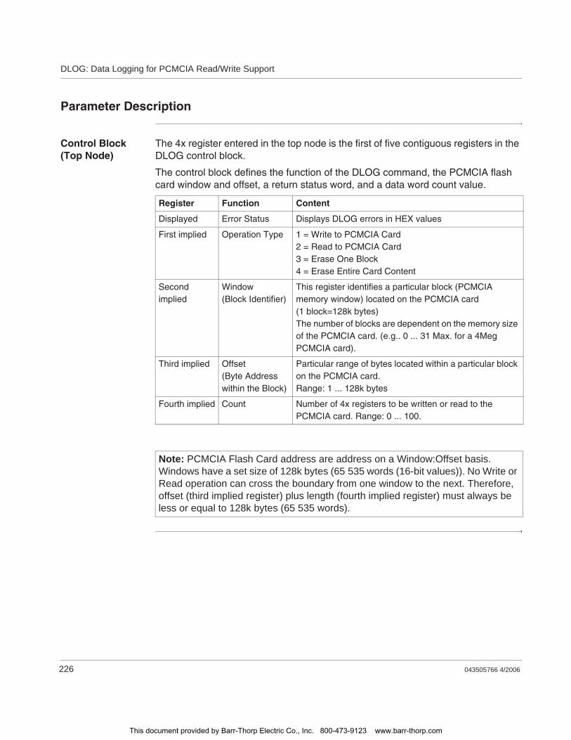
DLOG: Data Logging for PCMCIA Read/Write Support
226 043505766 4/2006
Parameter Description
Control Block (Top Node)
The 4x register entered in the top node is the first of five contiguous registers in the DLOG control block.
The control block defines the function of the DLOG command, the PCMCIA flash card window and offset, a return status word, and a data word count value.
Register Function Content
Displayed Error Status Displays DLOG errors in HEX values
First implied Operation Type 1 = Write to PCMCIA Card2 = Read to PCMCIA Card3 = Erase One Block4 = Erase Entire Card Content
Second implied
Window(Block Identifier)
This register identifies a particular block (PCMCIA memory window) located on the PCMCIA card (1 block=128k bytes)The number of blocks are dependent on the memory size of the PCMCIA card. (e.g.. 0 ... 31 Max. for a 4Meg PCMCIA card).
Third implied Offset(Byte Address within the Block)
Particular range of bytes located within a particular block on the PCMCIA card.Range: 1 ... 128k bytes
Fourth implied Count Number of 4x registers to be written or read to the PCMCIA card. Range: 0 ... 100.
Note: PCMCIA Flash Card address are address on a Window:Offset basis. Windows have a set size of 128k bytes (65 535 words (16-bit values)). No Write or Read operation can cross the boundary from one window to the next. Therefore, offset (third implied register) plus length (fourth implied register) must always be less or equal to 128k bytes (65 535 words).
This document provided by Barr-Thorp Electric Co., Inc. 800-473-9123 www.barr-thorp.com
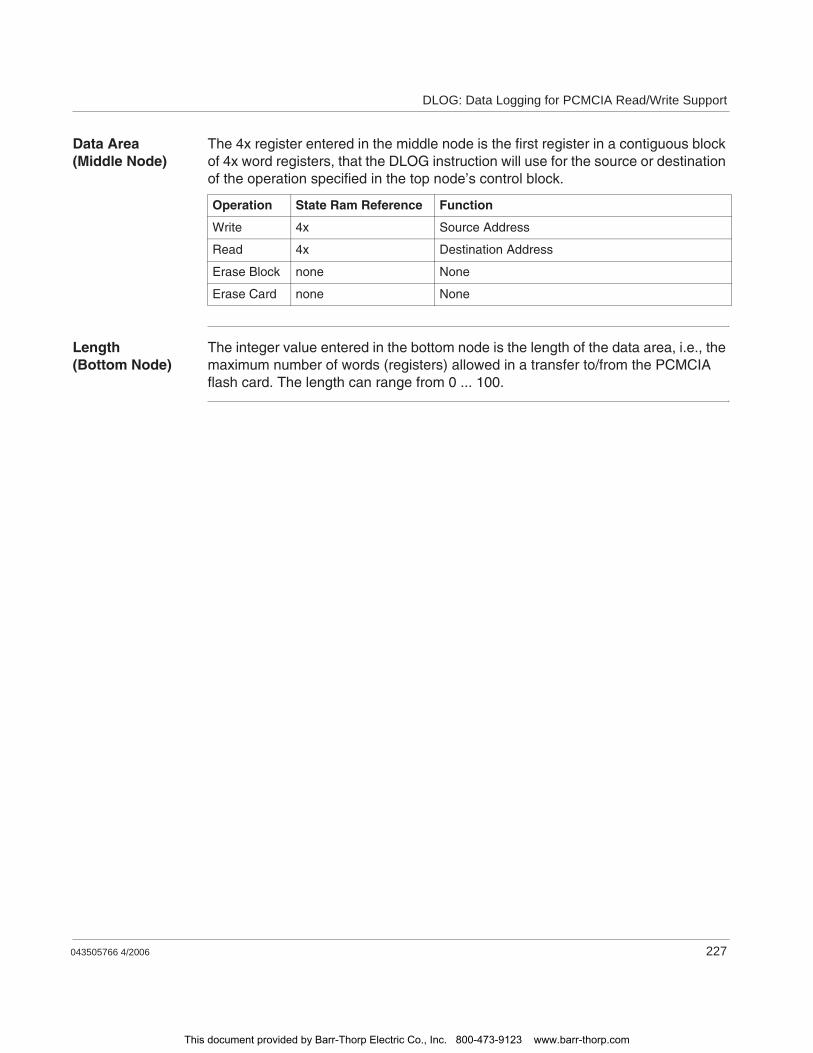
DLOG: Data Logging for PCMCIA Read/Write Support
043505766 4/2006 227
Data Area (Middle Node)
The 4x register entered in the middle node is the first register in a contiguous block of 4x word registers, that the DLOG instruction will use for the source or destination of the operation specified in the top node’s control block.
Length (Bottom Node)
The integer value entered in the bottom node is the length of the data area, i.e., the maximum number of words (registers) allowed in a transfer to/from the PCMCIA flash card. The length can range from 0 ... 100.
Operation State Ram Reference Function
Write 4x Source Address
Read 4x Destination Address
Erase Block none None
Erase Card none None
This document provided by Barr-Thorp Electric Co., Inc. 800-473-9123 www.barr-thorp.com
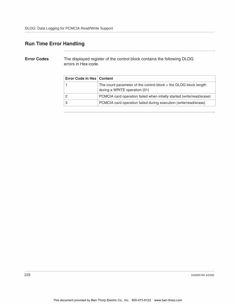
DLOG: Data Logging for PCMCIA Read/Write Support
228 043505766 4/2006
Run Time Error Handling
Error Codes The displayed register of the control block contains the following DLOG errors in Hex-code.
Error Code in Hex Content
1 The count parameter of the control block > the DLOG block length during a WRITE operation (01)
2 PCMCIA card operation failed when intially started (write/read/erase)
3 PCMCIA card operation failed during execution (write/read/erase)
This document provided by Barr-Thorp Electric Co., Inc. 800-473-9123 www.barr-thorp.com

043505766 4/2006 229
38DMTH - Double Precision Math
At a Glance
Introduction This chapter describes the four double precision math operations executed by the instruction DMTH. The four operations are Addition, Subtraction, Multiplication,and Division.
What's in this Chapter?
This chapter contains the following topics:
Topic Page
Short Description: DMTH - Double Precision Math - Addition, Subtraction, Multiplication, and Division
230
Representation: DMTH - Double Precision Math - Addition, Subtraction, Multiplication, and Division
231
This document provided by Barr-Thorp Electric Co., Inc. 800-473-9123 www.barr-thorp.com
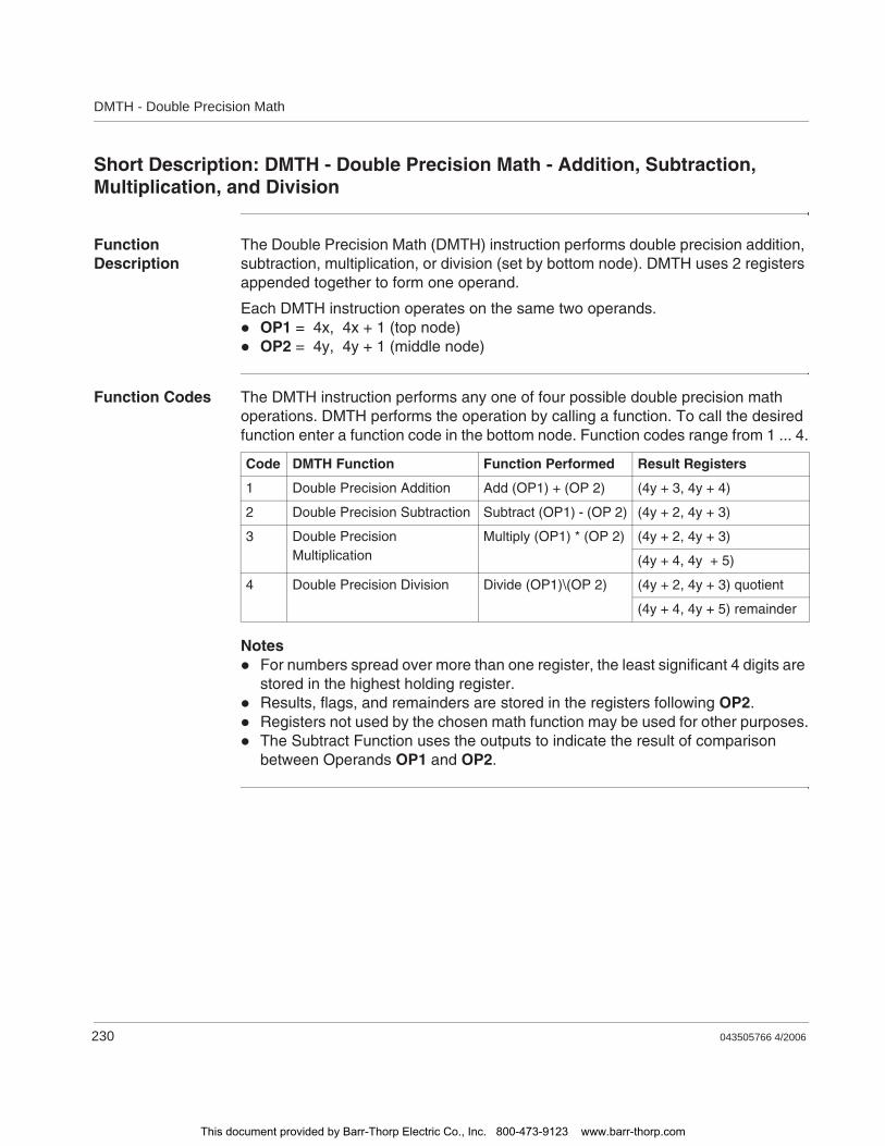
DMTH - Double Precision Math
230 043505766 4/2006
Short Description: DMTH - Double Precision Math - Addition, Subtraction, Multiplication, and Division
Function Description
The Double Precision Math (DMTH) instruction performs double precision addition, subtraction, multiplication, or division (set by bottom node). DMTH uses 2 registers appended together to form one operand.
Each DMTH instruction operates on the same two operands.OP1 = 4x, 4x + 1 (top node)OP2 = 4y, 4y + 1 (middle node)
Function Codes The DMTH instruction performs any one of four possible double precision math operations. DMTH performs the operation by calling a function. To call the desired function enter a function code in the bottom node. Function codes range from 1 ... 4.
NotesFor numbers spread over more than one register, the least significant 4 digits are stored in the highest holding register.Results, flags, and remainders are stored in the registers following OP2.Registers not used by the chosen math function may be used for other purposes.The Subtract Function uses the outputs to indicate the result of comparison between Operands OP1 and OP2.
Code DMTH Function Function Performed Result Registers
1 Double Precision Addition Add (OP1) + (OP 2) (4y + 3, 4y + 4)
2 Double Precision Subtraction Subtract (OP1) - (OP 2) (4y + 2, 4y + 3)
3 Double Precision Multiplication
Multiply (OP1) * (OP 2) (4y + 2, 4y + 3)
(4y + 4, 4y + 5)
4 Double Precision Division Divide (OP1)\(OP 2) (4y + 2, 4y + 3) quotient
(4y + 4, 4y + 5) remainder
This document provided by Barr-Thorp Electric Co., Inc. 800-473-9123 www.barr-thorp.com
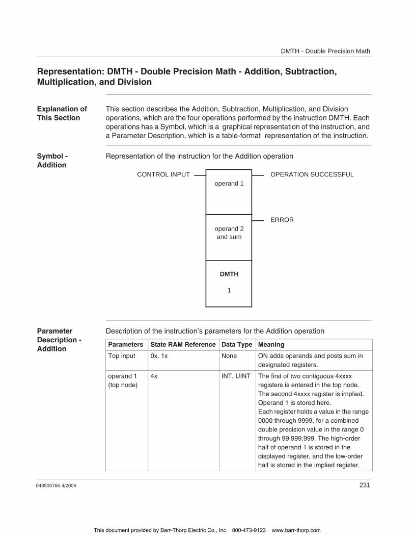
DMTH - Double Precision Math
043505766 4/2006 231
Representation: DMTH - Double Precision Math - Addition, Subtraction, Multiplication, and Division
Explanation of This Section
This section describes the Addition, Subtraction, Multiplication, and Division operations, which are the four operations performed by the instruction DMTH. Each operations has a Symbol, which is a graphical representation of the instruction, and a Parameter Description, which is a table-format representation of the instruction.
Symbol -Addition
Representation of the instruction for the Addition operation
Parameter Description - Addition
Description of the instruction’s parameters for the Addition operation
CONTROL INPUT OPERATION SUCCESSFUL
ERROR
operand 1
operand 2and sum
DMTH
1
Parameters State RAM Reference Data Type Meaning
Top input 0x, 1x None ON adds operands and posts sum in designated registers.
operand 1(top node)
4x INT, UINT The first of two contiguous 4xxxx registers is entered in the top node. The second 4xxxx register is implied. Operand 1 is stored here.Each register holds a value in the range 0000 through 9999, for a combined double precision value in the range 0 through 99,999,999. The high-order half of operand 1 is stored in the displayed register, and the low-order half is stored in the implied register.
This document provided by Barr-Thorp Electric Co., Inc. 800-473-9123 www.barr-thorp.com
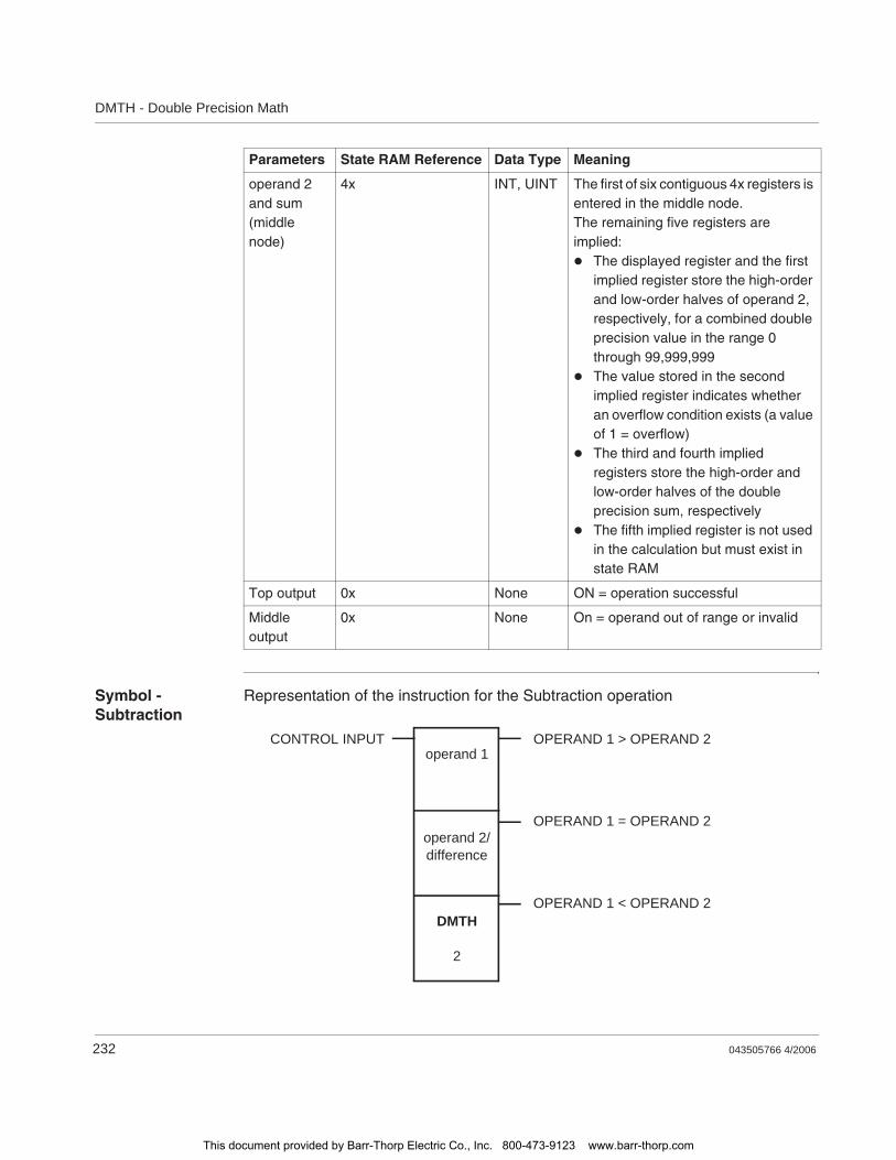
DMTH - Double Precision Math
232 043505766 4/2006
Symbol - Subtraction
Representation of the instruction for the Subtraction operation
operand 2 and sum(middle node)
4x INT, UINT The first of six contiguous 4x registers is entered in the middle node.The remaining five registers are implied:
The displayed register and the first implied register store the high-order and low-order halves of operand 2, respectively, for a combined double precision value in the range 0 through 99,999,999The value stored in the second implied register indicates whether an overflow condition exists (a value of 1 = overflow)The third and fourth implied registers store the high-order and low-order halves of the double precision sum, respectivelyThe fifth implied register is not used in the calculation but must exist in state RAM
Top output 0x None ON = operation successful
Middle output
0x None On = operand out of range or invalid
Parameters State RAM Reference Data Type Meaning
CONTROL INPUT OPERAND 1 > OPERAND 2
OPERAND 1 = OPERAND 2
OPERAND 1 < OPERAND 2
operand 1
operand 2/difference
DMTH
2
This document provided by Barr-Thorp Electric Co., Inc. 800-473-9123 www.barr-thorp.com
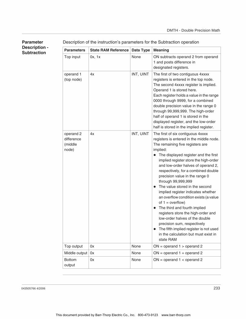
DMTH - Double Precision Math
043505766 4/2006 233
Parameter Description - Subtraction
Description of the instruction’s parameters for the Subtraction operation
Parameters State RAM Reference Data Type Meaning
Top input 0x, 1x None ON subtracts operand 2 from operand 1 and posts difference in designated registers.
operand 1(top node)
4x INT, UINT The first of two contiguous 4xxxx registers is entered in the top node. The second 4xxxx register is implied. Operand 1 is stored here.Each register holds a value in the range 0000 through 9999, for a combined double precision value in the range 0 through 99,999,999. The high-order half of operand 1 is stored in the displayed register, and the low-order half is stored in the implied register.
operand 2 difference(middle node)
4x INT, UINT The first of six contiguous 4xxxx registers is entered in the middle node.The remaining five registers are implied:
The displayed register and the first implied register store the high-order and low-order halves of operand 2, respectively, for a combined double precision value in the range 0 through 99,999,999The value stored in the second implied register indicates whether an overflow condition exists (a value of 1 = overflow)The third and fourth implied registers store the high-order and low-order halves of the double precision sum, respectivelyThe fifth implied register is not used in the calculation but must exist in state RAM
Top output 0x None ON = operand 1 > operand 2
Middle output 0x None ON = operand 1 = operand 2
Bottom output
0x None ON = operand 1 < operand 2
This document provided by Barr-Thorp Electric Co., Inc. 800-473-9123 www.barr-thorp.com
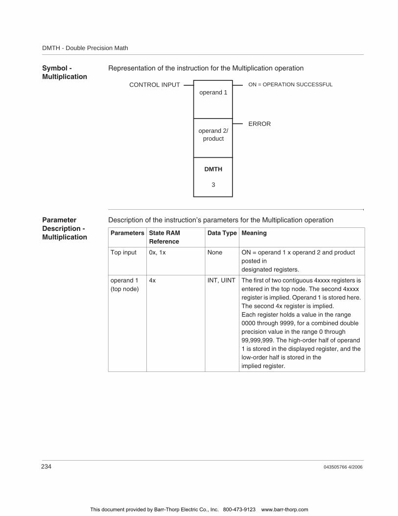
DMTH - Double Precision Math
234 043505766 4/2006
Symbol - Multiplication
Representation of the instruction for the Multiplication operation
Parameter Description - Multiplication
Description of the instruction’s parameters for the Multiplication operation
CONTROL INPUT ON = OPERATION SUCCESSFUL
ERROR
operand 1
operand 2/product
DMTH
3
Parameters State RAM Reference
Data Type Meaning
Top input 0x, 1x None ON = operand 1 x operand 2 and product posted in designated registers.
operand 1(top node)
4x INT, UINT The first of two contiguous 4xxxx registers is entered in the top node. The second 4xxxx register is implied. Operand 1 is stored here. The second 4x register is implied.Each register holds a value in the range 0000 through 9999, for a combined double precision value in the range 0 through 99,999,999. The high-order half of operand 1 is stored in the displayed register, and the low-order half is stored in theimplied register.
This document provided by Barr-Thorp Electric Co., Inc. 800-473-9123 www.barr-thorp.com

DMTH - Double Precision Math
043505766 4/2006 235
Symbol - Division
Representation of the instruction for the Division operation
operand 2/product(middle node)
4x INT, UINT The first of six contiguous 4xxxx registers is entered in the middle node.The remaining five registers are implied:
The displayed register and the first implied register store the high-order and low-order halves of operand 2, respectively, for a combined double precision value in the range 0 through 99,999,999The last four implied registers store the double precision product in the range 0 through 9,999,999,999,999,999
Top output 0x None ON = operation successful
Middle output
0x None ON = operand out of range
Parameters State RAM Reference
Data Type Meaning
CONTROL INPUT
REMAINDER
OPERATION SUCCESS-
ERROR
DIVIDE BY 0 ATTEMPT-ED
operand 1
operand 2quotient
DMTH
4
This document provided by Barr-Thorp Electric Co., Inc. 800-473-9123 www.barr-thorp.com
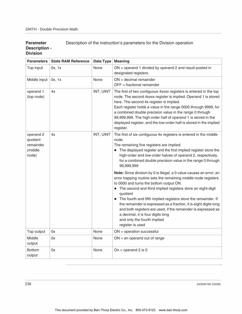
DMTH - Double Precision Math
236 043505766 4/2006
Parameter Description - Division
Description of the instruction’s parameters for the Division operation
Parameters State RAM Reference Data Type Meaning
Top input 0x, 1x None ON = operand 1 divided by operand 2 and result posted in designated registers.
Middle input 0x, 1x None ON = decimal remainderOFF = fractional remainder
operand 1(top node)
4x INT, UINT The first of two contiguous 4xxxx registers is entered in the top node. The second 4xxxx register is implied. Operand 1 is stored here. The second 4x register is implied.Each register holds a value in the range 0000 through 9999, for a combined double precision value in the range 0 through 99,999,999. The high-order half of operand 1 is stored in the displayed register, and the low-order half is stored in the implied register.
operand 2quotientremainder(middle node)
4x INT, UINT The first of six contiguous 4x registers is entered in the middle node. The remaining five registers are implied:
The displayed register and the first implied register store the high-order and low-order halves of operand 2, respectively, for a combined double precision value in the range 0 through 99,999,999
Note: Since division by 0 is illegal, a 0 value causes an error; an error trapping routine sets the remaining middle-node registers to 0000 and turns the bottom output ON.
The second and third implied registers store an eight-digit quotientThe fourth and fifth implied registers store the remainder. If the remainder is expressed as a fraction, it is eight digits long and both registers are used, if the remainder is expressed as a decimal, it is four digits long and only the fourth implied register is used
Top output 0x None ON = operation successful
Middle output
0x None ON = an operand out of range
Bottom output
0x None On = operand 2 is 0
This document provided by Barr-Thorp Electric Co., Inc. 800-473-9123 www.barr-thorp.com

043505766 4/2006 237
39DRUM: DRUM Sequencer
At a Glance
Introduction This chapter describes the instruction DRUM.
What's in this Chapter?
This chapter contains the following topics:
Topic Page
Short Description 238
Representation: DRUM 239
Parameter Description 241
This document provided by Barr-Thorp Electric Co., Inc. 800-473-9123 www.barr-thorp.com
DRUM: DRUM Sequencer
238 043505766 4/2006
Short Description
Function Description
The DRUM instruction operates on a table of 4x registers containing data representing each step in a sequence. The number of registers associated with this step data table depends on the number of steps required in the sequence. You can pre-allocate registers to store data for each step in the sequence, thereby allowing you to add future sequencer steps without having to modify application logic.
DRUM incorporates an output mask that allows you to selectively mask bits in the register data before writing it to coils. This is particularly useful when all physical sequencer outputs are not contiguous on the output module. Masked bits are not altered by the DRUM instruction, and may be used by logic unrelated to the sequencer.
Note: This instruction is only available if you have unpacked and installed the DX Loadables. For further information, see p. 101."
This document provided by Barr-Thorp Electric Co., Inc. 800-473-9123 www.barr-thorp.com
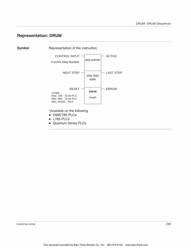
DRUM: DRUM Sequencer
043505766 4/2006 239
Representation: DRUM
Symbol Representation of the instruction
*Available on the followingE685/785 PLCsL785 PLCsQuantum Series PLCs
DRUM
length
step data table
step pointerCONTROL INPUT ACTIVE
ERRORRESET
LAST STEPNEXT STEP
Current Step Number
Length:Max. 255 - 16-bit PLCMax. 999 - 24-bit PLCMax. 65535 - *PLC
This document provided by Barr-Thorp Electric Co., Inc. 800-473-9123 www.barr-thorp.com
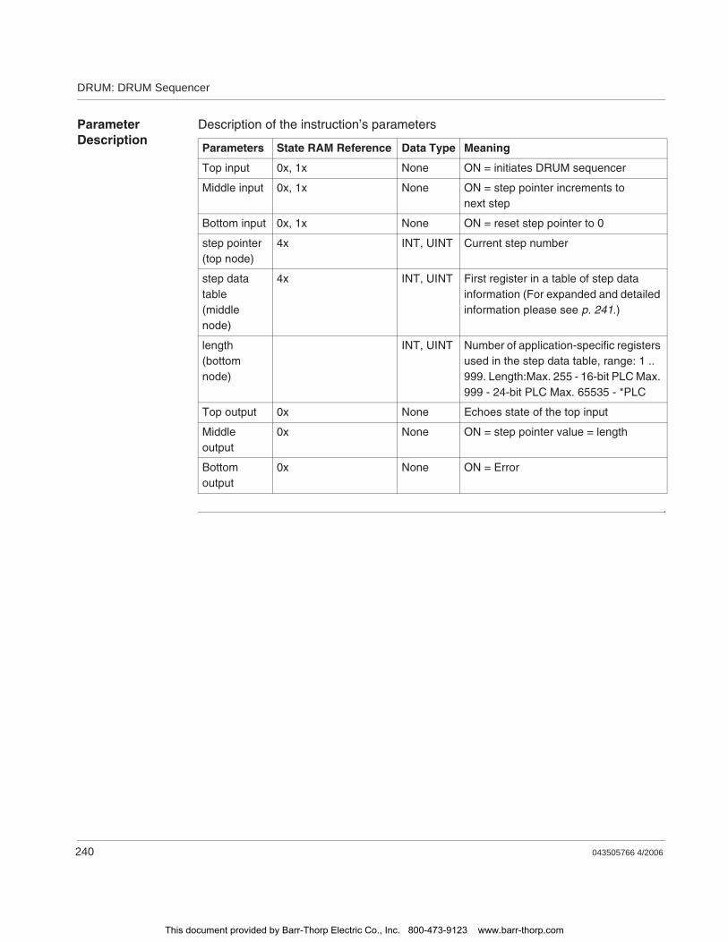
DRUM: DRUM Sequencer
240 043505766 4/2006
Parameter Description
Description of the instruction’s parameters
Parameters State RAM Reference Data Type Meaning
Top input 0x, 1x None ON = initiates DRUM sequencer
Middle input 0x, 1x None ON = step pointer increments to next step
Bottom input 0x, 1x None ON = reset step pointer to 0
step pointer(top node)
4x INT, UINT Current step number
step data table(middle node)
4x INT, UINT First register in a table of step data information (For expanded and detailed information please see p. 241.)
length(bottom node)
INT, UINT Number of application-specific registers used in the step data table, range: 1 .. 999. Length:Max. 255 - 16-bit PLC Max. 999 - 24-bit PLC Max. 65535 - *PLC
Top output 0x None Echoes state of the top input
Middle output
0x None ON = step pointer value = length
Bottom output
0x None ON = Error
This document provided by Barr-Thorp Electric Co., Inc. 800-473-9123 www.barr-thorp.com
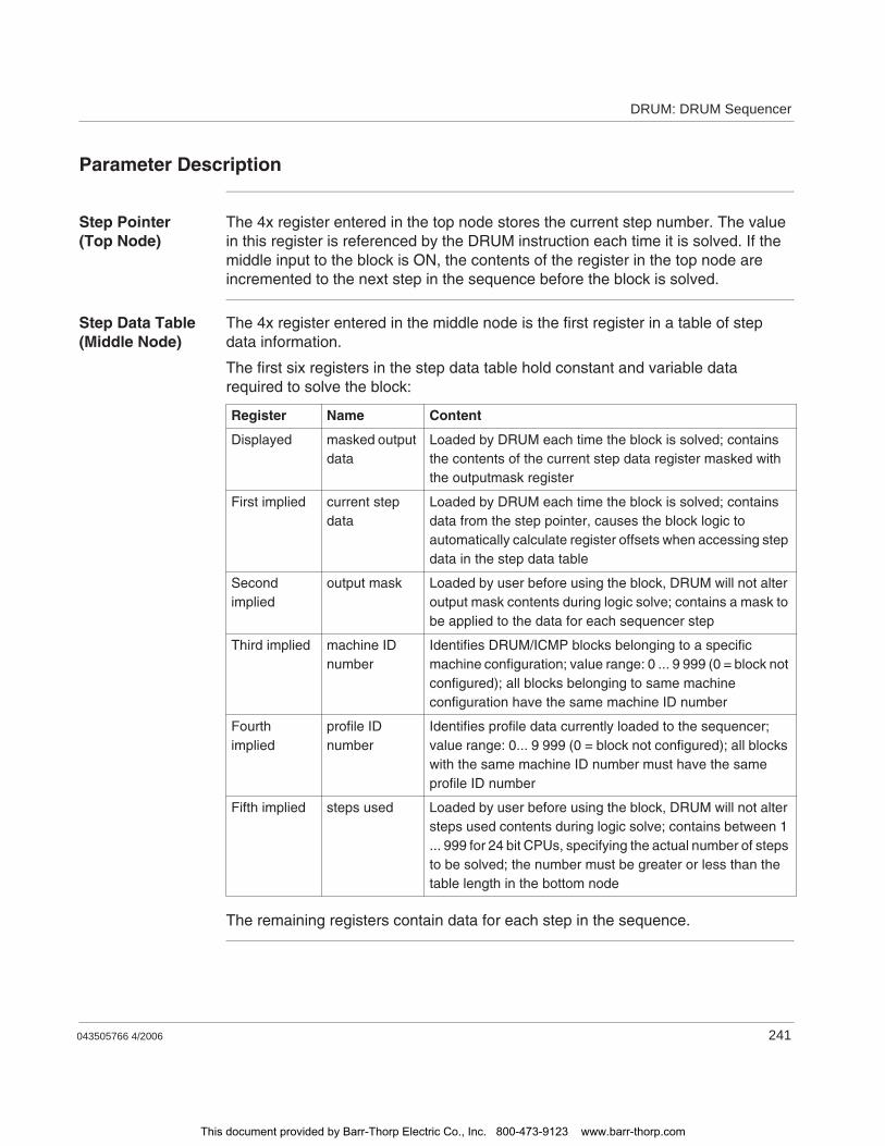
DRUM: DRUM Sequencer
043505766 4/2006 241
Parameter Description
Step Pointer (Top Node)
The 4x register entered in the top node stores the current step number. The value in this register is referenced by the DRUM instruction each time it is solved. If the middle input to the block is ON, the contents of the register in the top node are incremented to the next step in the sequence before the block is solved.
Step Data Table (Middle Node)
The 4x register entered in the middle node is the first register in a table of step data information.
The first six registers in the step data table hold constant and variable data required to solve the block:
The remaining registers contain data for each step in the sequence.
Register Name Content
Displayed masked output data
Loaded by DRUM each time the block is solved; contains the contents of the current step data register masked with the outputmask register
First implied current step data
Loaded by DRUM each time the block is solved; contains data from the step pointer, causes the block logic to automatically calculate register offsets when accessing step data in the step data table
Second implied
output mask Loaded by user before using the block, DRUM will not alter output mask contents during logic solve; contains a mask to be applied to the data for each sequencer step
Third implied machine ID number
Identifies DRUM/ICMP blocks belonging to a specific machine configuration; value range: 0 ... 9 999 (0 = block not configured); all blocks belonging to same machine configuration have the same machine ID number
Fourth implied
profile ID number
Identifies profile data currently loaded to the sequencer; value range: 0... 9 999 (0 = block not configured); all blocks with the same machine ID number must have the same profile ID number
Fifth implied steps used Loaded by user before using the block, DRUM will not alter steps used contents during logic solve; contains between 1 ... 999 for 24 bit CPUs, specifying the actual number of steps to be solved; the number must be greater or less than the table length in the bottom node
This document provided by Barr-Thorp Electric Co., Inc. 800-473-9123 www.barr-thorp.com

DRUM: DRUM Sequencer
242 043505766 4/2006
Length (Bottom Node)
The integer value entered in the bottom node is the length, i.e., the number of application-specific registers used in the step data table. The length can range from 1 ... 999 in a 24-bit CPU.
The total number of registers required in the step data table is the length + 6. The length must be greater or equal to the value placed in the steps used register in the middle node.
This document provided by Barr-Thorp Electric Co., Inc. 800-473-9123 www.barr-thorp.com

043505766 4/2006 243
40DV16: Divide 16 Bit
At a Glance
Introduction This chapter describes the instruction DV16.
What's in this Chapter?
This chapter contains the following topics:
Topic Page
Short Description 244
Representation: DV16 - 16-bit Division 245
Example 247
This document provided by Barr-Thorp Electric Co., Inc. 800-473-9123 www.barr-thorp.com

DV16: Divide 16 Bit
244 043505766 4/2006
Short Description
Function Description
The DV16 instruction performs a signed or unsigned division on the 16-bit values in the top and middle nodes (value 1 / value 2), then posts the quotient and remainder in two contiguous 4x holding registers in the bottom node.
This document provided by Barr-Thorp Electric Co., Inc. 800-473-9123 www.barr-thorp.com
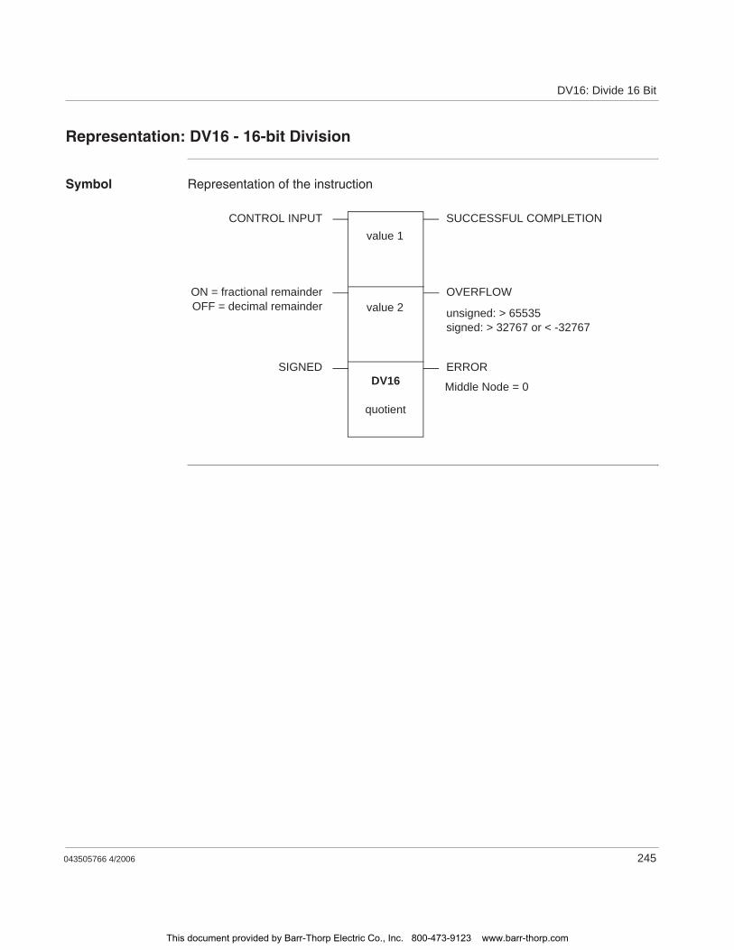
DV16: Divide 16 Bit
043505766 4/2006 245
Representation: DV16 - 16-bit Division
Symbol Representation of the instruction
DV16
quotient
value 2
value 1CONTROL INPUT SUCCESSFUL COMPLETION
ERRORSIGNED
OVERFLOWON = fractional remainderOFF = decimal remainder unsigned: > 65535
signed: > 32767 or < -32767
Middle Node = 0
This document provided by Barr-Thorp Electric Co., Inc. 800-473-9123 www.barr-thorp.com
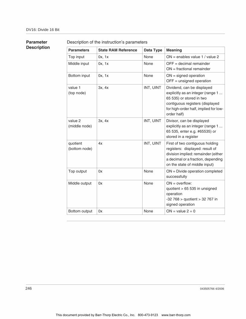
DV16: Divide 16 Bit
246 043505766 4/2006
Parameter Description
Description of the instruction’s parameters
Parameters State RAM Reference Data Type Meaning
Top input 0x, 1x None ON = enables value 1 / value 2
Middle input 0x, 1x None OFF = decimal remainderON = fractional remainder
Bottom input 0x, 1x None ON = signed operationOFF = unsigned operation
value 1(top node)
3x, 4x INT, UINT Dividend, can be displayed explicitly as an integer (range 1 ... 65 535) or stored in two contiguous registers (displayed for high-order half, implied for low-order half)
value 2(middle node)
3x, 4x INT, UINT Divisor, can be displayed explicitly as an integer (range 1 ... 65 535, enter e.g. #65535) or stored in a register
quotient(bottom node)
4x INT, UINT First of two contiguous holding registers: displayed: result of division implied: remainder (either a decimal or a fraction, depending on the state of middle input)
Top output 0x None ON = Divide operation completed successfully
Middle output 0x None ON = overflow:quotient > 65 535 in unsigned operation-32 768 > quotient > 32 767 in signed operation
Bottom output 0x None ON = value 2 = 0
This document provided by Barr-Thorp Electric Co., Inc. 800-473-9123 www.barr-thorp.com

DV16: Divide 16 Bit
043505766 4/2006 247
Example
Quotient of Instruction DV16
The state of the middle input indicates whether the remainder will be expressed as a decimal or as a fraction. For example, if value 1 = 8 and value 2 = 3, the decimal remainder (middle input OFF) is 6666; the fractional remainder (middle input ON) is 2.
This document provided by Barr-Thorp Electric Co., Inc. 800-473-9123 www.barr-thorp.com

DV16: Divide 16 Bit
248 043505766 4/2006
This document provided by Barr-Thorp Electric Co., Inc. 800-473-9123 www.barr-thorp.com

043505766 4/2006 xxxi
Glossary
active window The window, which is currently selected. Only one window can be active at any one given time. When a window is active, the heading changes color, in order to distinguish it from other windows. Unselected windows are inactive.
Actual parameter Currently connected Input/Output parameters.
Addresses (Direct) addresses are memory areas on the PLC. These are found in the State RAM and can be assigned input/output modules.The display/input of direct addresses is possible in the following formats:
Standard format (400001)Separator format (4:00001)Compact format (4:1)IEC format (QW1)
ANL_IN ANL_IN stands for the data type "Analog Input" and is used for processing analog values. The 3x References of the configured analog input module, which is specified in the I/O component list is automatically assigned the data type and should therefore only be occupied by Unlocated variables.
ANL_OUT ANL_OUT stands for the data type "Analog Output" and is used for processing analog values. The 4x-References of the configured analog output module, which is specified in the I/O component list is automatically assigned the data type and should therefore only be occupied by Unlocated variables.
ANY In the existing version "ANY" covers the elementary data types BOOL, BYTE, DINT, INT, REAL, UDINT, UINT, TIME and WORD and therefore derived data types.
A
This document provided by Barr-Thorp Electric Co., Inc. 800-473-9123 www.barr-thorp.com

Glossary
xxxii 043505766 4/2006
ANY_BIT In the existing version, "ANY_BIT" covers the data types BOOL, BYTE and WORD.
ANY_ELEM In the existing version "ANY_ELEM" covers the elementary data types BOOL, BYTE, DINT, INT, REAL, UDINT, UINT, TIME and WORD.
ANY_INT In the existing version, "ANY_INT" covers the data types DINT, INT, UDINT and UINT.
ANY_NUM In the existing version, "ANY_NUM" covers the data types DINT, INT, REAL, UDINT and UINT.
ANY_REAL In the existing version "ANY_REAL" covers the data type REAL.
Application window
The window, which contains the working area, the menu bar and the tool bar for the application. The name of the application appears in the heading. An application window can contain several document windows. In Concept the application window corresponds to a Project.
Argument Synonymous with Actual parameters.
ASCII mode American Standard Code for Information Interchange. The ASCII mode is used for communication with various host devices. ASCII works with 7 data bits.
Atrium The PC based controller is located on a standard AT board, and can be operated within a host computer in an ISA bus slot. The module occupies a motherboard (requires SA85 driver) with two slots for PC104 daughter boards. From this, a PC104 daughter board is used as a CPU and the others for INTERBUS control.
This document provided by Barr-Thorp Electric Co., Inc. 800-473-9123 www.barr-thorp.com

Glossary
043505766 4/2006 xxxiii
Back up data file (Concept EFB)
The back up file is a copy of the last Source files. The name of this back up file is "backup??.c" (it is accepted that there are no more than 100 copies of the source files. The first back up file is called "backup00.c". If changes have been made on the Definition file, which do not create any changes to the interface in the EFB, there is no need to create a back up file by editing the source files (Objects Source). If a back up file can be assigned, the name of the source file can be given.
Base 16 literals Base 16 literals function as the input of whole number values in the hexadecimal system. The base must be denoted by the prefix 16#. The values may not be preceded by signs (+/-). Single underline signs ( _ ) between figures are not significant.
Example 16#F_F or 16#FF (decimal 255)16#E_0 or 16#E0 (decimal 224)
Base 8 literal Base 8 literals function as the input of whole number values in the octal system. The base must be denoted by the prefix 3.63kg. The values may not be preceded by signs (+/-). Single underline signs ( _ ) between figures are not significant.
Example 8#3_1111 or 8#377 (decimal 255) 8#34_1111 or 8#340 (decimal 224)
Basis 2 literals Base 2 literals function as the input of whole number values in the dual system. The base must be denoted by the prefix 0.91kg. The values may not be preceded by signs (+/-). Single underline signs ( _ ) between figures are not significant.
Example 2#1111_1111 or 2#11111111 (decimal 255) 2#1110_1111 or 2#11100000 (decimal 224)
Binary connections
Connections between outputs and inputs of FFBs of data type BOOL.
Bit sequence A data element, which is made up from one or more bits.
BOOL BOOL stands for the data type "Boolean". The length of the data elements is 1 bit (in the memory contained in 1 byte). The range of values for variables of this type is 0 (FALSE) and 1 (TRUE).
B
This document provided by Barr-Thorp Electric Co., Inc. 800-473-9123 www.barr-thorp.com
Glossary
xxxiv 043505766 4/2006
Bridge A bridge serves to connect networks. It enables communication between nodes on the two networks. Each network has its own token rotation sequence – the token is not deployed via bridges.
BYTE BYTE stands for the data type "Bit sequence 8". The input appears as Base 2 literal, Base 8 literal or Base 1 16 literal. The length of the data element is 8 bit. A numerical range of values cannot be assigned to this data type.
Cache The cache is a temporary memory for cut or copied objects. These objects can be inserted into sections. The old content in the cache is overwritten for each new Cut or Copy.
Call up The operation, by which the execution of an operation is initiated.
Coil A coil is a LD element, which transfers (without alteration) the status of the horizontal link on the left side to the horizontal link on the right side. In this way, the status is saved in the associated Variable/ direct address.
Compact format (4:1)
The first figure (the Reference) is separated from the following address with a colon (:), where the leading zero are not entered in the address.
Connection A check or flow of data connection between graphic objects (e.g. steps in the SFC editor, Function blocks in the FBD editor) within a section, is graphically shown as a line.
Constants Constants are Unlocated variables, which are assigned a value that cannot be altered from the program logic (write protected).
Contact A contact is a LD element, which transfers a horizontal connection status onto the right side. This status is from the Boolean AND- operation of the horizontal connection status on the left side with the status of the associated Variables/direct Address. A contact does not alter the value of the associated variables/direct address.
C
This document provided by Barr-Thorp Electric Co., Inc. 800-473-9123 www.barr-thorp.com
Glossary
043505766 4/2006 xxxv
Data transfer settings
Settings, which determine how information from the programming device is transferred to the PLC.
Data types The overview shows the hierarchy of data types, as they are used with inputs and outputs of Functions and Function blocks. Generic data types are denoted by the prefix "ANY".
ANY_ELEMANY_NUMANY_REAL (REAL)ANY_INT (DINT, INT, UDINT, UINT)ANY_BIT (BOOL, BYTE, WORD)TIME
System data types (IEC extensions)Derived (from "ANY" data types)
DCP I/O station With a Distributed Control Processor (D908) a remote network can be set up with a parent PLC. When using a D908 with remote PLC, the parent PLC views the remote PLC as a remote I/O station. The D908 and the remote PLC communicate via the system bus, which results in high performance, with minimum effect on the cycle time. The data exchange between the D908 and the parent PLC takes place at 1.5 Megabits per second via the remote I/O bus. A parent PLC can support up to 31 (Address 2-32) D908 processors.
DDE (Dynamic Data Exchange)
The DDE interface enables a dynamic data exchange between two programs under Windows. The DDE interface can be used in the extended monitor to call up its own display applications. With this interface, the user (i.e. the DDE client) can not only read data from the extended monitor (DDE server), but also write data onto the PLC via the server. Data can therefore be altered directly in the PLC, while it monitors and analyzes the results. When using this interface, the user is able to make their own "Graphic-Tool", "Face Plate" or "Tuning Tool", and integrate this into the system. The tools can be written in any DDE supporting language, e.g. Visual Basic and Visual-C++. The tools are called up, when the one of the buttons in the dialog box extended monitor uses Concept Graphic Tool: Signals of a projection can be displayed as timing diagrams via the DDE connection between Concept and Concept Graphic Tool.
D
This document provided by Barr-Thorp Electric Co., Inc. 800-473-9123 www.barr-thorp.com
Glossary
xxxvi 043505766 4/2006
Decentral Network (DIO)
A remote programming in Modbus Plus network enables maximum data transfer performance and no specific requests on the links. The programming of a remote net is easy. To set up the net, no additional ladder diagram logic is needed. Via corresponding entries into the Peer Cop processor all data transfer requests are met.
Declaration Mechanism for determining the definition of a Language element. A declaration normally covers the connection of an Identifier with a language element and the assignment of attributes such as Data types and algorithms.
Definition data file (Concept EFB)
The definition file contains general descriptive information about the selected FFB and its formal parameters.
Derived data type Derived data types are types of data, which are derived from the Elementary data types and/or other derived data types. The definition of the derived data types appears in the data type editor in Concept.Distinctions are made between global data types and local data types.
Derived Function Block (DFB)
A derived function block represents the Call up of a derived function block type. Details of the graphic form of call up can be found in the definition " Function block (Item)". Contrary to calling up EFB types, calling up DFB types is denoted by double vertical lines on the left and right side of the rectangular block symbol.The body of a derived function block type is designed using FBD language, but only in the current version of the programming system. Other IEC languages cannot yet be used for defining DFB types, nor can derived functions be defined in the current version. Distinctions are made between local and global DFBs.
DINT DINT stands for the data type "double integer". The input appears as Integer literal, Base 2 literal, Base 8 literal or Base 16 literal. The length of the data element is 32 bit. The range of values for variables of this data type is from –2 exp (31) to 2 exp (31) –1.
Direct display A method of displaying variables in the PLC program, from which the assignment of configured memory can be directly and indirectly derived from the physical memory.
Document window
A window within an Application window. Several document windows can be opened at the same time in an application window. However, only one document window can be active. Document windows in Concept are, for example, sections, the message window, the reference data editor and the PLC configuration.
Dummy An empty data file, which consists of a text header with general file information, i.e. author, date of creation, EFB identifier etc. The user must complete this dummy file with additional entries.
This document provided by Barr-Thorp Electric Co., Inc. 800-473-9123 www.barr-thorp.com
Glossary
043505766 4/2006 xxxvii
DX Zoom This property enables connection to a programming object to observe and, if necessary, change its data value.
Elementary functions/function blocks (EFB)
Identifier for Functions or Function blocks, whose type definitions are not formulated in one of the IEC languages, i.e. whose bodies, for example, cannot be modified with the DFB Editor (Concept-DFB). EFB types are programmed in "C" and mounted via Libraries in precompiled form.
EN / ENO (Enable / Error display)
If the value of EN is "0" when the FFB is called up, the algorithms defined by the FFB are not executed and all outputs contain the previous value. The value of ENO is automatically set to "0" in this case. If the value of EN is "1" when the FFB is called up, the algorithms defined by the FFB are executed. After the error free execution of the algorithms, the ENO value is automatically set to "1". If an error occurs during the execution of the algorithm, ENO is automatically set to "0". The output behavior of the FFB depends whether the FFBs are called up without EN/ENO or with EN=1. If the EN/ENO display is enabled, the EN input must be active. Otherwise, the FFB is not executed. The projection of EN and ENO is enabled/disabled in the block properties dialog box. The dialog box is called up via the menu commands Objects
Properties... or via a double click on the FFB.
Error When processing a FFB or a Step an error is detected (e.g. unauthorized input value or a time error), an error message appears, which can be viewed with the menu command Online Event display... . With FFBs the ENO output is set to "0".
Evaluation The process, by which a value for a Function or for the outputs of a Function block during the Program execution is transmitted.
Expression Expressions consist of operators and operands.
E
This document provided by Barr-Thorp Electric Co., Inc. 800-473-9123 www.barr-thorp.com
Glossary
xxxviii 043505766 4/2006
FFB (functions/function blocks)
Collective term for EFB (elementary functions/function blocks) and DFB (derived function blocks)
Field variables Variables, one of which is assigned, with the assistance of the key word ARRAY (field), a defined Derived data type. A field is a collection of data elements of the same Data type.
FIR filter Finite Impulse Response Filter
Formal parameters
Input/Output parameters, which are used within the logic of a FFB and led out of the FFB as inputs/outputs.
Function (FUNC) A Program organization unit, which exactly supplies a data element when executing. A function has no internal status information. Multiple call ups of the same function with the same input parameter values always supply the same output values.Details of the graphic form of function call up can be found in the definition " Function block (Item)". In contrast to the call up of function blocks, the function call ups only have one unnamed output, whose name is the name of the function itself. In FBD each call up is denoted by a unique number over the graphic block; this number is automatically generated and cannot be altered.
Function block (item) (FB)
A function block is a Program organization unit, which correspondingly calculates the functionality values, defined in the function block type description, for the output and internal variables, when it is called up as a certain item. All output values and internal variables of a certain function block item remain as a call up of the function block until the next. Multiple call up of the same function block item with the same arguments (Input parameter values) supply generally supply the same output value(s).Each function block item is displayed graphically by a rectangular block symbol. The name of the function block type is located on the top center within the rectangle. The name of the function block item is located also at the top, but on the outside of the rectangle. An instance is automatically generated when creating, which can however be altered manually, if required. Inputs are displayed on the left side and outputs on the right of the block. The names of the formal input/output parameters are displayed within the rectangle in the corresponding places.The above description of the graphic presentation is principally applicable to Function call ups and to DFB call ups. Differences are described in the corresponding definitions.
F
This document provided by Barr-Thorp Electric Co., Inc. 800-473-9123 www.barr-thorp.com
Glossary
043505766 4/2006 xxxix
Function block dialog (FBD)
One or more sections, which contain graphically displayed networks from Functions, Function blocks and Connections.
Function block type
A language element, consisting of: 1. the definition of a data structure, subdivided into input, output and internal variables, 2. A set of operations, which is used with the elements of the data structure, when a function block type instance is called up. This set of operations can be formulated either in one of the IEC languages (DFB type) or in "C" (EFB type). A function block type can be instanced (called up) several times.
Function counter The function counter serves as a unique identifier for the function in a Program or DFB. The function counter cannot be edited and is automatically assigned. The function counter always has the structure: .n.mn = Section number (number running)m = Number of the FFB object in the section (number running)
Generic data type
A Data type, which stands in for several other data types.
Generic literal If the Data type of a literal is not relevant, simply enter the value for the literal. In this case Concept automatically assigns the literal to a suitable data type.
Global derived data types
Global Derived data types are available in every Concept project and are contained in the DFB directory directly under the Concept directory.
Global DFBs Global DFBs are available in every Concept project and are contained in the DFB directory directly under the Concept directory.
Global macros Global Macros are available in every Concept project and are contained in the DFB directory directly under the Concept directory.
Groups (EFBs) Some EFB libraries (e.g. the IEC library) are subdivided into groups. This facilitates the search for FFBs, especially in extensive libraries.
G
This document provided by Barr-Thorp Electric Co., Inc. 800-473-9123 www.barr-thorp.com
Glossary
xl 043505766 4/2006
I/O component list
The I/O and expert assemblies of the various CPUs are configured in the I/O component list.
IEC 61131-3 International norm: Programmable controllers – part 3: Programming languages.
IEC format (QW1) In the place of the address stands an IEC identifier, followed by a five figure address:%0x12345 = %Q12345%1x12345 = %I12345%3x12345 = %IW12345%4x12345 = %QW12345
IEC name conventions (identifier)
An identifier is a sequence of letters, figures, and underscores, which must start with a letter or underscores (e.g. name of a function block type, of an item or section). Letters from national sets of characters (e.g. ö,ü, é, õ) can be used, taken from project and DFB names.Underscores are significant in identifiers; e.g. "A_BCD" and "AB_CD" are interpreted as different identifiers. Several leading and multiple underscores are not authorized consecutively.Identifiers are not permitted to contain space characters. Upper and/or lower case is not significant; e.g. "ABCD" and "abcd" are interpreted as the same identifier.Identifiers are not permitted to be Key words.
IIR filter Infinite Impulse Response Filter
Initial step (starting step)
The first step in a chain. In each chain, an initial step must be defined. The chain is started with the initial step when first called up.
Initial value The allocated value of one of the variables when starting the program. The value assignment appears in the form of a Literal.
Input bits (1x references)
The 1/0 status of input bits is controlled via the process data, which reaches the CPU from an entry device.
Input parameters (Input)
When calling up a FFB the associated Argument is transferred.
I
Note: The x, which comes after the first figure of the reference type, represents a five figure storage location in the application data store, i.e. if the reference 100201 signifies an input bit in the address 201 of the State RAM.
This document provided by Barr-Thorp Electric Co., Inc. 800-473-9123 www.barr-thorp.com
Glossary
043505766 4/2006 xli
Input words (3x references)
An input word contains information, which come from an external source and are represented by a 16 bit figure. A 3x register can also contain 16 sequential input bits, which were read into the register in binary or BCD (binary coded decimal) format. Note: The x, which comes after the first figure of the reference type, represents a five figure storage location in the user data store, i.e. if the reference 300201 signifies a 16 bit input word in the address 201 of the State RAM.
Instantiation The generation of an Item.
Instruction (IL) Instructions are "commands" of the IL programming language. Each operation begins on a new line and is succeeded by an operator (with modifier if needed) and, if necessary for each relevant operation, by one or more operands. If several operands are used, they are separated by commas. A tag can stand before the instruction, which is followed by a colon. The commentary must, if available, be the last element in the line.
Instruction (LL984)
When programming electric controllers, the task of implementing operational coded instructions in the form of picture objects, which are divided into recognizable contact forms, must be executed. The designed program objects are, on the user level, converted to computer useable OP codes during the loading process. The OP codes are deciphered in the CPU and processed by the controller’s firmware functions so that the desired controller is implemented.
Instruction list (IL)
IL is a text language according to IEC 1131, in which operations, e.g. conditional/unconditional call up of Function blocks and Functions, conditional/unconditional jumps etc. are displayed through instructions.
INT INT stands for the data type "whole number". The input appears as Integer literal, Base 2 literal, Base 8 literal or Base 16 literal. The length of the data element is 16 bit. The range of values for variables of this data type is from –2 exp (15) to 2 exp (15) –1.
Integer literals Integer literals function as the input of whole number values in the decimal system. The values may be preceded by the signs (+/-). Single underline signs ( _ ) between figures are not significant.
Example -12, 0, 123_456, +986
INTERBUS (PCP) To use the INTERBUS PCP channel and the INTERBUS process data preprocessing (PDP), the new I/O station type INTERBUS (PCP) is led into the Concept configurator. This I/O station type is assigned fixed to the INTERBUS connection module 180-CRP-660-01.The 180-CRP-660-01 differs from the 180-CRP-660-00 only by a clearly larger I/O area in the state RAM of the controller.
This document provided by Barr-Thorp Electric Co., Inc. 800-473-9123 www.barr-thorp.com
Glossary
xlii 043505766 4/2006
Item name An Identifier, which belongs to a certain Function block item. The item name serves as a unique identifier for the function block in a program organization unit. The item name is automatically generated, but can be edited. The item name must be unique throughout the Program organization unit, and no distinction is made between upper/lower case. If the given name already exists, a warning is given and another name must be selected. The item name must conform to the IEC name conventions, otherwise an error message appears. The automatically generated instance name always has the structure: FBI_n_m
FBI = Function block itemn = Section number (number running)m = Number of the FFB object in the section (number running)
Jump Element of the SFC language. Jumps are used to jump over areas of the chain.
Key words Key words are unique combinations of figures, which are used as special syntactic elements, as is defined in appendix B of the IEC 1131-3. All key words, which are used in the IEC 1131-3 and in Concept, are listed in appendix C of the IEC 1131-3. These listed keywords cannot be used for any other purpose, i.e. not as variable names, section names, item names etc.
J
K
This document provided by Barr-Thorp Electric Co., Inc. 800-473-9123 www.barr-thorp.com
Glossary
043505766 4/2006 xliii
Ladder Diagram (LD)
Ladder Diagram is a graphic programming language according to IEC1131, which optically orientates itself to the "rung" of a relay ladder diagram.
Ladder Logic 984 (LL)
In the terms Ladder Logic and Ladder Diagram, the word Ladder refers to execution. In contrast to a diagram, a ladder logic is used by engineers to draw up a circuit (with assistance from electrical symbols),which should chart the cycle of events and not the existing wires, which connect the parts together. A usual user interface for controlling the action by automated devices permits ladder logic interfaces, so that when implementing a control system, engineers do not have to learn any new programming languages, with which they are not conversant.The structure of the actual ladder logic enables electrical elements to be linked in a way that generates a control output, which is dependant upon a configured flow of power through the electrical objects used, which displays the previously demanded condition of a physical electric appliance.In simple form, the user interface is one of the video displays used by the PLC programming application, which establishes a vertical and horizontal grid, in which the programming objects are arranged. The logic is powered from the left side of the grid, and by connecting activated objects the electricity flows from left to right.
Landscape format
Landscape format means that the page is wider than it is long when looking at the printed text.
Language element
Each basic element in one of the IEC programming languages, e.g. a Step in SFC, a Function block item in FBD or the Start value of a variable.
Library Collection of software objects, which are provided for reuse when programming new projects, or even when building new libraries. Examples are the Elementary function block types libraries.EFB libraries can be subdivided into Groups.
Literals Literals serve to directly supply values to inputs of FFBs, transition conditions etc. These values cannot be overwritten by the program logic (write protected). In this way, generic and standardized literals are differentiated.Furthermore literals serve to assign a Constant a value or a Variable an Initial value. The input appears as Base 2 literal, Base 8 literal, Base 16 literal, Integer literal, Real literal or Real literal with exponent.
Local derived data types
Local derived data types are only available in a single Concept project and its local DFBs and are contained in the DFB directory under the project directory.
L
This document provided by Barr-Thorp Electric Co., Inc. 800-473-9123 www.barr-thorp.com
Glossary
xliv 043505766 4/2006
Local DFBs Local DFBs are only available in a single Concept project and are contained in the DFB directory under the project directory.
Local link The local network link is the network, which links the local nodes with other nodes either directly or via a bus amplifier.
Local macros Local Macros are only available in a single Concept project and are contained in the DFB directory under the project directory.
Local network nodes
The local node is the one, which is projected evenly.
Located variable Located variables are assigned a state RAM address (reference addresses 0x,1x, 3x, 4x). The value of these variables is saved in the state RAM and can be altered online with the reference data editor. These variables can be addressed by symbolic names or the reference addresses.
Collective PLC inputs and outputs are connected to the state RAM. The program access to the peripheral signals, which are connected to the PLC, appears only via located variables. PLC access from external sides via Modbus or Modbus plus interfaces, i.e. from visualizing systems, are likewise possible via located variables.
This document provided by Barr-Thorp Electric Co., Inc. 800-473-9123 www.barr-thorp.com
Glossary
043505766 4/2006 xlv
Macro Macros are created with help from the software Concept DFB.Macros function to duplicate frequently used sections and networks (including the logic, variables, and variable declaration).Distinctions are made between local and global macros.
Macros have the following properties:Macros can only be created in the programming languages FBD and LD.Macros only contain one single section.Macros can contain any complex section.From a program technical point of view, there is no differentiation between an instanced macro, i.e. a macro inserted into a section, and a conventionally created macro.Calling up DFBs in a macroVariable declarationUse of macro-own data structuresAutomatic acceptance of the variables declared in the macroInitial value for variablesMultiple instancing of a macro in the whole program with different variablesThe section name, the variable name and the data structure name can contain up to 10 different exchange markings (@0 to @9).
MMI Man Machine Interface
Multi element variables
Variables, one of which is assigned a Derived data type defined with STRUCT or ARRAY.Distinctions are made between Field variables and structured variables.
M
This document provided by Barr-Thorp Electric Co., Inc. 800-473-9123 www.barr-thorp.com
Glossary
xlvi 043505766 4/2006
Network A network is the connection of devices to a common data path, which communicate with each other via a common protocol.
Network node A node is a device with an address (164) on the Modbus Plus network.
Node address The node address serves a unique identifier for the network in the routing path. The address is set directly on the node, e.g. with a rotary switch on the back of the module.
Operand An operand is a Literal, a Variable, a Function call up or an Expression.
Operator An operator is a symbol for an arithmetic or Boolean operation to be executed.
Output parameters (Output)
A parameter, with which the result(s) of the Evaluation of a FFB are returned.
Output/discretes (0x references)
An output/marker bit can be used to control real output data via an output unit of the control system, or to define one or more outputs in the state RAM. Note: The x, which comes after the first figure of the reference type, represents a five figure storage location in the application data store, i.e. if the reference 000201 signifies an output or marker bit in the address 201 of the State RAM.
Output/marker words (4x references)
An output/marker word can be used to save numerical data (binary or decimal) in the State RAM, or also to send data from the CPU to an output unit in the control system. Note: The x, which comes after the first figure of the reference type, represents a five figure storage location in the application data store, i.e. if the reference 400201 signifies a 16 bit output or marker word in the address 201 of the State RAM.
N
O
This document provided by Barr-Thorp Electric Co., Inc. 800-473-9123 www.barr-thorp.com
Glossary
043505766 4/2006 xlvii
Peer processor The peer processor processes the token run and the flow of data between the Modbus Plus network and the PLC application logic.
PLC Programmable controller
Program The uppermost Program organization unit. A program is closed and loaded onto a single PLC.
Program cycle A program cycle consists of reading in the inputs, processing the program logic and the output of the outputs.
Program organization unit
A Function, a Function block, or a Program. This term can refer to either a Type or an Item.
Programming device
Hardware and software, which supports programming, configuring, testing, implementing and error searching in PLC applications as well as in remote system applications, to enable source documentation and archiving. The programming device could also be used for process visualization.
Programming redundancy system (Hot Standby)
A redundancy system consists of two identically configured PLC devices, which communicate with each other via redundancy processors. In the case of the primary PLC failing, the secondary PLC takes over the control checks. Under normal conditions the secondary PLC does not take over any controlling functions, but instead checks the status information, to detect mistakes.
Project General identification of the uppermost level of a software tree structure, which specifies the parent project name of a PLC application. After specifying the project name, the system configuration and control program can be saved under this name. All data, which results during the creation of the configuration and the program, belongs to this parent project for this special automation.General identification for the complete set of programming and configuring information in the Project data bank, which displays the source code that describes the automation of a system.
Project data bank The data bank in the Programming device, which contains the projection information for a Project.
Prototype data file (Concept EFB)
The prototype data file contains all prototypes of the assigned functions. Further, if available, a type definition of the internal status structure is given.
P
This document provided by Barr-Thorp Electric Co., Inc. 800-473-9123 www.barr-thorp.com

Glossary
xlviii 043505766 4/2006
REAL REAL stands for the data type "real". The input appears as Real literal or as Real literal with exponent. The length of the data element is 32 bit. The value range for variables of this data type reaches from 8.43E-37 to 3.36E+38.
Real literal Real literals function as the input of real values in the decimal system. Real literals are denoted by the input of the decimal point. The values may be preceded by the signs (+/-). Single underline signs ( _ ) between figures are not significant.
Example -12.0, 0.0, +0.456, 3.14159_26
Real literal with exponent
Real literals with exponent function as the input of real values in the decimal system. Real literals with exponent are denoted by the input of the decimal point. The exponent sets the key potency, by which the preceding number is multiplied to get to the value to be displayed. The basis may be preceded by a negative sign (-). The exponent may be preceded by a positive or negative sign (+/-). Single underline signs ( _ ) between figures are not significant. (Only between numbers, not before or after the decimal poiont and not before or after "E", "E+" or "E-")
Example -1.34E-12 or -1.34e-12 1.0E+6 or 1.0e+61.234E6 or 1.234e6
Reference Each direct address is a reference, which starts with an ID, specifying whether it concerns an input or an output and whether it concerns a bit or a word. References, which start with the code 6, display the register in the extended memory of the state RAM. 0x area = Discrete outputs 1x area = Input bits 3x area = Input words 4x area = Output bits/Marker words 6x area = Register in the extended memory
R
Note: Depending on the mathematic processor type of the CPU, various areas within this valid value range cannot be represented. This is valid for values nearing ZERO and for values nearing INFINITY. In these cases, a number value is not shown in animation, instead NAN (Not A Number) oder INF (INFinite).
This document provided by Barr-Thorp Electric Co., Inc. 800-473-9123 www.barr-thorp.com
Glossary
043505766 4/2006 xlix
Register in the extended memory (6x reference)
6x references are marker words in the extended memory of the PLC. Only LL984 user programs and CPU 213 04 or CPU 424 02 can be used.
RIO (Remote I/O) Remote I/O provides a physical location of the I/O coordinate setting device in relation to the processor to be controlled. Remote inputs/outputs are connected to the consumer control via a wired communication cable.
RP (PROFIBUS) RP = Remote Peripheral
RTU mode Remote Terminal UnitThe RTU mode is used for communication between the PLC and an IBM compatible personal computer. RTU works with 8 data bits.
Rum-time error Error, which occurs during program processing on the PLC, with SFC objects (i.e. steps) or FFBs. These are, for example, over-runs of value ranges with figures, or time errors with steps.
SA85 module The SA85 module is a Modbus Plus adapter for an IBM-AT or compatible computer.
Section A section can be used, for example, to describe the functioning method of a technological unit, such as a motor.A Program or DFB consist of one or more sections. Sections can be programmed with the IEC programming languages FBD and SFC. Only one of the named programming languages can be used within a section.Each section has its own Document window in Concept. For reasons of clarity, it is recommended to subdivide a very large section into several small ones. The scroll bar serves to assist scrolling in a section.
Separator format (4:00001)
The first figure (the Reference) is separated from the ensuing five figure address by a colon (:).
Note: The x, which comes after the first figure of each reference type, represents a five figure storage location in the application data store, i.e. if the reference 400201 signifies a 16 bit output or marker word in the address 201 of the State RAM.
S
This document provided by Barr-Thorp Electric Co., Inc. 800-473-9123 www.barr-thorp.com
Glossary
l 043505766 4/2006
Sequence language (SFC)
The SFC Language elements enable the subdivision of a PLC program organiza-tional unit in a number of Steps and Transitions, which are connected horizontally by aligned Connections. A number of actions belong to each step, and a transition condition is linked to a transition.
Serial ports With serial ports (COM) the information is transferred bit by bit.
Source code data file (Concept EFB)
The source code data file is a usual C++ source file. After execution of the menu command Library Generate data files this file contains an EFB code framework, in which a specific code must be entered for the selected EFB. To do this, click on the menu command Objects Source.
Standard format (400001)
The five figure address is located directly after the first figure (the reference).
Standardized literals
If the data type for the literal is to be automatically determined, use the following construction: ’Data type name’#’Literal value’.
Example INT#15 (Data type: Integer, value: 15), BYTE#00001111 (data type: Byte, value: 00001111) REAL#23.0 (Data type: Real, value: 23.0)
For the assignment of REAL data types, there is also the possibility to enter the value in the following way: 23.0. Entering a comma will automatically assign the data type REAL.
State RAM The state RAM is the storage for all sizes, which are addressed in the user program via References (Direct display). For example, input bits, discretes, input words, and discrete words are located in the state RAM.
Statement (ST) Instructions are "commands" of the ST programming language. Instructions must be terminated with semicolons. Several instructions (separated by semi-colons) can occupy the same line.
Status bits There is a status bit for every node with a global input or specific input/output of Peer Cop data. If a defined group of data was successfully transferred within the set time out, the corresponding status bit is set to 1. Alternatively, this bit is set to 0 and all data belonging to this group (of 0) is deleted.
Step SFC Language element: Situations, in which the Program behavior follows in relation to the inputs and outputs of the same operations, which are defined by the associated actions of the step.
This document provided by Barr-Thorp Electric Co., Inc. 800-473-9123 www.barr-thorp.com
Glossary
043505766 4/2006 li
Step name The step name functions as the unique flag of a step in a Program organization unit. The step name is automatically generated, but can be edited. The step name must be unique throughout the whole program organization unit, otherwise an Error message appears. The automatically generated step name always has the structure: S_n_m
S = Step n = Section number (number running)m = Number of steps in the section (number running)
Structured text (ST)
ST is a text language according to IEC 1131, in which operations, e.g. call up of Function blocks and Functions, conditional execution of instructions, repetition of instructions etc. are displayed through instructions.
Structured variables
Variables, one of which is assigned a Derived data type defined with STRUCT (structure).A structure is a collection of data elements with generally differing data types ( Elementary data types and/or derived data types).
SY/MAX In Quantum control devices, Concept closes the mounting on the I/O population SY/MAX I/O modules for RIO control via the Quantum PLC with on. The SY/MAX remote subrack has a remote I/O adapter in slot 1, which communicates via a Modicon S908 R I/O system. The SY/MAX I/O modules are performed when highlighting and including in the I/O population of the Concept configuration.
Symbol (Icon) Graphic display of various objects in Windows, e.g. drives, user programs and Document windows.
Template data file (Concept EFB)
The template data file is an ASCII data file with a layout information for the Concept FBD editor, and the parameters for code generation.
TIME TIME stands for the data type "Time span". The input appears as Time span literal. The length of the data element is 32 bit. The value range for variables of this type stretches from 0 to 2exp(32)-1. The unit for the data type TIME is 1 ms.
Time span literals
Permitted units for time spans (TIME) are days (D), hours (H), minutes (M), seconds (S) and milliseconds (MS) or a combination thereof. The time span must be denoted by the prefix t#, T#, time# or TIME#. An "overrun" of the highest ranking unit is permitted, i.e. the input T#25H15M is permitted.
T
This document provided by Barr-Thorp Electric Co., Inc. 800-473-9123 www.barr-thorp.com
Glossary
lii 043505766 4/2006
Example t#14MS, T#14.7S, time#18M, TIME#19.9H, t#20.4D, T#25H15M, time#5D14H12M18S3.5MS
Token The network "Token" controls the temporary property of the transfer rights via a single node. The token runs through the node in a circulating (rising) address sequence. All nodes track the Token run through and can contain all possible data sent with it.
Traffic Cop The Traffic Cop is a component list, which is compiled from the user component list. The Traffic Cop is managed in the PLC and in addition contains the user component list e.g. Status information of the I/O stations and modules.
Transition The condition with which the control of one or more Previous steps transfers to one or more ensuing steps along a directional Link.
UDEFB User defined elementary functions/function blocksFunctions or Function blocks, which were created in the programming language C, and are available in Concept Libraries.
UDINT UDINT stands for the data type "unsigned double integer". The input appears as Integer literal, Base 2 literal, Base 8 literal or Base 16 literal. The length of the data element is 32 bit. The value range for variables of this type stretches from 0 to 2exp(32)-1.
UINT UINT stands for the data type "unsigned integer". The input appears as Integer literal, Base 2 literal, Base 8 literal or Base 16 literal. The length of the data element is 16 bit. The value range for variables of this type stretches from 0 to (2exp16)-1.
Unlocated variable
Unlocated variables are not assigned any state RAM addresses. They therefore do not occupy any state RAM addresses. The value of these variables is saved in the system and can be altered with the reference data editor. These variables are only addressed by symbolic names.
Signals requiring no peripheral access, e.g. intermediate results, system tags etc, should primarily be declared as unlocated variables.
U
This document provided by Barr-Thorp Electric Co., Inc. 800-473-9123 www.barr-thorp.com

Glossary
043505766 4/2006 liii
Variables Variables function as a data exchange within sections between several sections and between the Program and the PLC.Variables consist of at least a variable name and a Data type.Should a variable be assigned a direct Address (Reference), it is referred to as a Located variable. Should a variable not be assigned a direct address, it is referred to as an unlocated variable. If the variable is assigned a Derived data type, it is referred to as a Multi-element variable.Otherwise there are Constants and Literals.
Vertical format Vertical format means that the page is higher than it is wide when looking at the printed text.
Warning When processing a FFB or a Step a critical status is detected (e.g. critical input value or a time out), a warning appears, which can be viewed with the menu command Online Event display... . With FFBs the ENO output remains at "1".
WORD WORD stands for the data type "Bit sequence 16". The input appears as Base 2 literal, Base 8 literal or Base 1 16 literal. The length of the data element is 16 bit. A numerical range of values cannot be assigned to this data type.
V
W
This document provided by Barr-Thorp Electric Co., Inc. 800-473-9123 www.barr-thorp.com

Glossary
liv 043505766 4/2006
This document provided by Barr-Thorp Electric Co., Inc. 800-473-9123 www.barr-thorp.com
CBA
043505766 4/2006 lv
Numerics3x or 4x register
entering in mathematical equation, 57
AABS, 64AD16, 109ADD, 113Add 16 Bit, 109Addition, 113
AD16, 109ADD, 113
Advanced Calculations, 782algebraic expression
equation network, 54algebraic notation
equation network, 51Analog Input, 787Analog Output, 799Analog Values, 71AND, 117ARCCOS, 64ARCSIN, 64ARCTAN, 64argument
equation network, 64limits, 65
arithmetic operator, 59ASCII Functions
READ, 937WRIT, 1091
assignment operator, 59Average Weighted Inputs Calculate, 803
BBase 10 Antilogarithm, 279Base 10 Logarithm, 383BCD, 123benchmark performance
equation network, 69Binary to Binary Code, 123Bit Control, 755Bit pattern comparison
CMPR, 167Bit Rotate, 139bitwise operator, 59BLKM, 127BLKT, 131Block Move, 127Block Move with Interrupts Disabled, 135Block to Table, 131BMDI, 135boolean, 56BROT, 139
CCalculated preset formula, 809Central Alarm Handler, 793Changing the Sign of a Floating Point Number, 301Check Sum, 163
Index
This document provided by Barr-Thorp Electric Co., Inc. 800-473-9123 www.barr-thorp.com
Index
lvi 043505766 4/2006
CHS, 157CKSM, 163Closed Loop Control, 71CMPR, 167coil
equation network, 53error messages, 53
Coils, 91Communications
MSTR, 701COMP, 179Compare Register, 167Complement a Matrix, 179Comprehensive ISA Non Interacting PID, 831conditional expression
equation network, 51, 61conditional operator, 59Configure Hot Standby, 157constant
equation network, 51constant data
floating point, 57long (32-bit), 57LSB (least signifcant byte), 57mathematical equation, 57
Contacts, 91Convertion
BCD to binary, 123binary to BCD, 123
COS, 64COSD, 64Counters / Timers
T.01 Timer, 1049T0.1 Timer, 1053T1.0 Timer, 1057T1MS Timer, 1061UCTR, 1077
Counters/TimersDCTR, 203
creating equation network, 52
Ddata
mathematical equation, 56data conversions
equation network, 66Data Logging for PCMCIA Read/Write Support, 223DCTR, 203Derivative Rate Calculation over a Specified Time, 883DIOH, 207discrete reference
mathematical equation, 56Distributed I/O Health, 207DIV, 217Divide, 217Divide 16 Bit, 243DLOG, 223Double Precision Addition, 265Double Precision Division, 347Double Precision Multiplication, 395Double Precision Subtraction, 447Down Counter, 203DRUM, 237DRUM Sequencer, 237DV16, 243
This document provided by Barr-Thorp Electric Co., Inc. 800-473-9123 www.barr-thorp.com
Index
043505766 4/2006 lvii
EEMTH, 259EMTH Subfunction
EMTH-ADDDP, 265EMTH-ADDFP, 271, 275EMTH-ANLOG, 279EMTH-ARCOS, 285EMTH-ARSIN, 291EMTH-ARTAN, 295EMTH-CHSIN, 301EMTH-CMPFP, 307EMTH-CMPIF, 313EMTH-CNVDR, 319EMTH-CNVFI, 325EMTH-CNVIF, 331EMTH-CNVRD, 337EMTH-COS, 343EMTH-DIVDP, 347EMTH-DIVFI, 353EMTH-DIVFP, 357EMTH-DIVIF, 361EMTH-ERLOG, 365EMTH-EXP, 371EMTH-LNFP, 377EMTH-LOG, 383EMTH-LOGFP, 389EMTH-MULDP, 395EMTH-MULFP, 401EMTH-MULIF, 405EMTH-PI, 411EMTH-POW, 417EMTH-SINE, 423EMTH-SQRFP, 429EMTH-SQRT, 435EMTH-SQRTP, 441EMTH-SUBDP, 447EMTH-SUBFI, 453EMTH-SUBFP, 457EMTH-SUBIF, 461EMTH-TAN, 465
EMTH-ADDDP, 265EMTH-ADDFP, 271EMTH-ADDIF, 275EMTH-ANLOG, 279EMTH-ARCOS, 285
EMTH-ARSIN, 291EMTH-ARTAN, 295EMTH-CHSIN, 301EMTH-CMPFP, 307EMTH-CMPIF, 313EMTH-CNVDR, 319EMTH-CNVFI, 325EMTH-CNVIF, 331EMTH-CNVRD, 337EMTH-COS, 343EMTH-DIVDP, 347EMTH-DIVFI, 353EMTH-DIVFP, 357EMTH-DIVIF, 361EMTH-ERLOG, 365EMTH-EXP, 371EMTH-LNFP, 377EMTH-LOG, 383EMTH-LOGFP, 389EMTHMULDP, 395EMTH-MULFP, 401EMTH-MULIF, 405EMTH-PI, 411EMTH-POW, 417EMTH-SINE, 423EMTH-SQRFP, 429EMTH-SQRT, 435EMTH-SQRTP, 441EMTH-SUBDP, 447EMTH-SUBFI, 453EMTH-SUBFP, 457EMTH-SUBIF, 461EMTH-TAN, 465enable contact
horizontal open, 53horizontal short, 53normally closed, 53normally open, 53
Engineering Unit Conversion and Alarms, 489
This document provided by Barr-Thorp Electric Co., Inc. 800-473-9123 www.barr-thorp.com
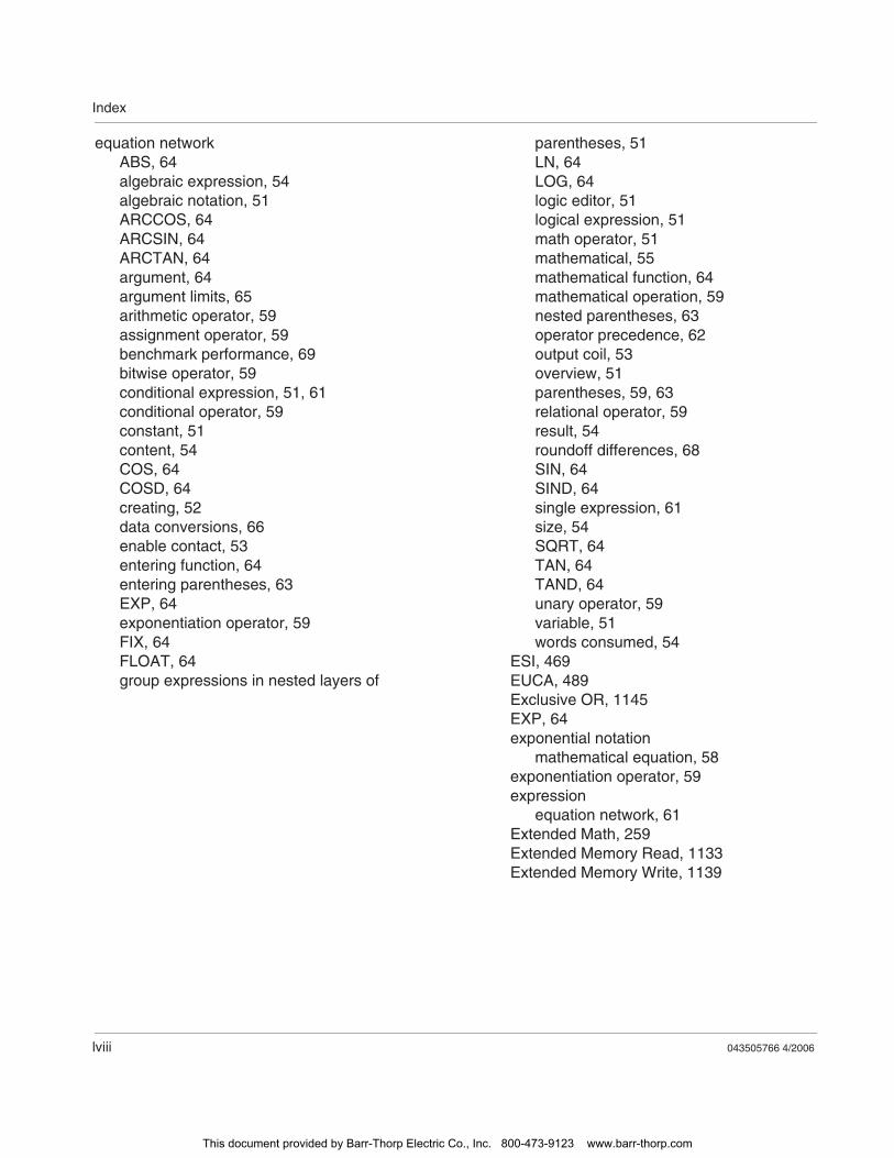
Index
lviii 043505766 4/2006
equation networkABS, 64algebraic expression, 54algebraic notation, 51ARCCOS, 64ARCSIN, 64ARCTAN, 64argument, 64argument limits, 65arithmetic operator, 59assignment operator, 59benchmark performance, 69bitwise operator, 59conditional expression, 51, 61conditional operator, 59constant, 51content, 54COS, 64COSD, 64creating, 52data conversions, 66enable contact, 53entering function, 64entering parentheses, 63EXP, 64exponentiation operator, 59FIX, 64FLOAT, 64group expressions in nested layers of
parentheses, 51LN, 64LOG, 64logic editor, 51logical expression, 51math operator, 51mathematical, 55mathematical function, 64mathematical operation, 59nested parentheses, 63operator precedence, 62output coil, 53overview, 51parentheses, 59, 63relational operator, 59result, 54roundoff differences, 68SIN, 64SIND, 64single expression, 61size, 54SQRT, 64TAN, 64TAND, 64unary operator, 59variable, 51words consumed, 54
ESI, 469EUCA, 489Exclusive OR, 1145EXP, 64exponential notation
mathematical equation, 58exponentiation operator, 59expression
equation network, 61Extended Math, 259Extended Memory Read, 1133Extended Memory Write, 1139
This document provided by Barr-Thorp Electric Co., Inc. 800-473-9123 www.barr-thorp.com
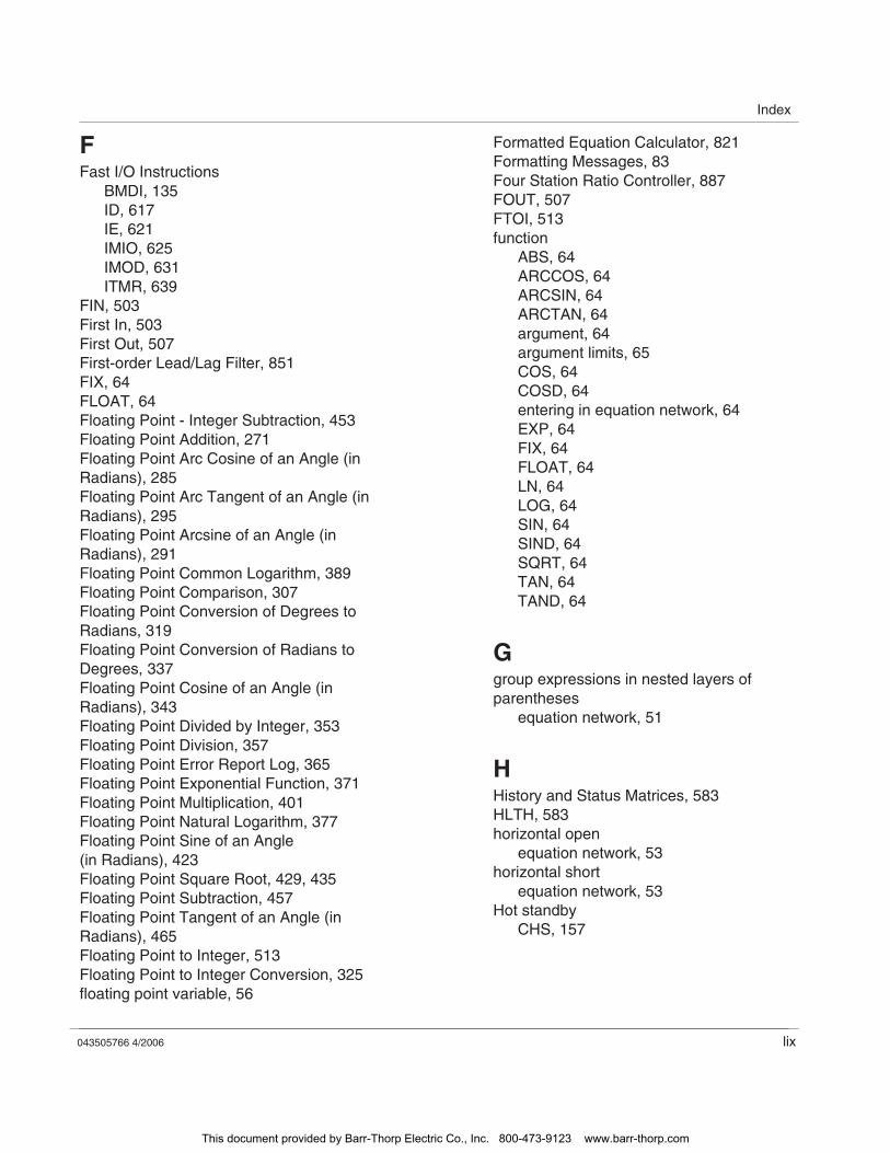
Index
043505766 4/2006 lix
FFast I/O Instructions
BMDI, 135ID, 617IE, 621IMIO, 625IMOD, 631ITMR, 639
FIN, 503First In, 503First Out, 507First-order Lead/Lag Filter, 851FIX, 64FLOAT, 64Floating Point - Integer Subtraction, 453Floating Point Addition, 271Floating Point Arc Cosine of an Angle (in Radians), 285Floating Point Arc Tangent of an Angle (in Radians), 295Floating Point Arcsine of an Angle (in Radians), 291Floating Point Common Logarithm, 389Floating Point Comparison, 307Floating Point Conversion of Degrees to Radians, 319Floating Point Conversion of Radians to Degrees, 337Floating Point Cosine of an Angle (in Radians), 343Floating Point Divided by Integer, 353Floating Point Division, 357Floating Point Error Report Log, 365Floating Point Exponential Function, 371Floating Point Multiplication, 401Floating Point Natural Logarithm, 377Floating Point Sine of an Angle (in Radians), 423Floating Point Square Root, 429, 435Floating Point Subtraction, 457Floating Point Tangent of an Angle (in Radians), 465Floating Point to Integer, 513Floating Point to Integer Conversion, 325floating point variable, 56
Formatted Equation Calculator, 821Formatting Messages, 83Four Station Ratio Controller, 887FOUT, 507FTOI, 513function
ABS, 64ARCCOS, 64ARCSIN, 64ARCTAN, 64argument, 64argument limits, 65COS, 64COSD, 64entering in equation network, 64EXP, 64FIX, 64FLOAT, 64LN, 64LOG, 64SIN, 64SIND, 64SQRT, 64TAN, 64TAND, 64
Ggroup expressions in nested layers of parentheses
equation network, 51
HHistory and Status Matrices, 583HLTH, 583horizontal open
equation network, 53horizontal short
equation network, 53Hot standby
CHS, 157
This document provided by Barr-Thorp Electric Co., Inc. 800-473-9123 www.barr-thorp.com
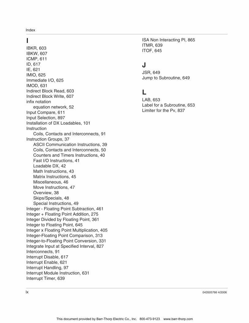
Index
lx 043505766 4/2006
IIBKR, 603IBKW, 607ICMP, 611ID, 617IE, 621IMIO, 625Immediate I/O, 625IMOD, 631Indirect Block Read, 603Indirect Block Write, 607infix notation
equation network, 52Input Compare, 611Input Selection, 897Installation of DX Loadables, 101Instruction
Coils, Contacts and Interconnects, 91Instruction Groups, 37
ASCII Communication Instructions, 39Coils, Contacts and Interconnects, 50Counters and Timers Instructions, 40Fast I/O Instructions, 41Loadable DX, 42Math Instructions, 43Matrix Instructions, 45Miscellaneous, 46Move Instructions, 47Overview, 38Skips/Specials, 48Special Instructions, 49
Integer - Floating Point Subtraction, 461Integer + Floating Point Addition, 275Integer Divided by Floating Point, 361Integer to Floating Point, 645Integer x Floating Point Multiplication, 405Integer-Floating Point Comparison, 313Integer-to-Floating Point Conversion, 331Integrate Input at Specified Interval, 827Interconnects, 91Interrupt Disable, 617Interrupt Enable, 621Interrupt Handling, 97Interrupt Module Instruction, 631Interrupt Timer, 639
ISA Non Interacting PI, 865ITMR, 639ITOF, 645
JJSR, 649Jump to Subroutine, 649
LLAB, 653Label for a Subroutine, 653Limiter for the Pv, 837
This document provided by Barr-Thorp Electric Co., Inc. 800-473-9123 www.barr-thorp.com
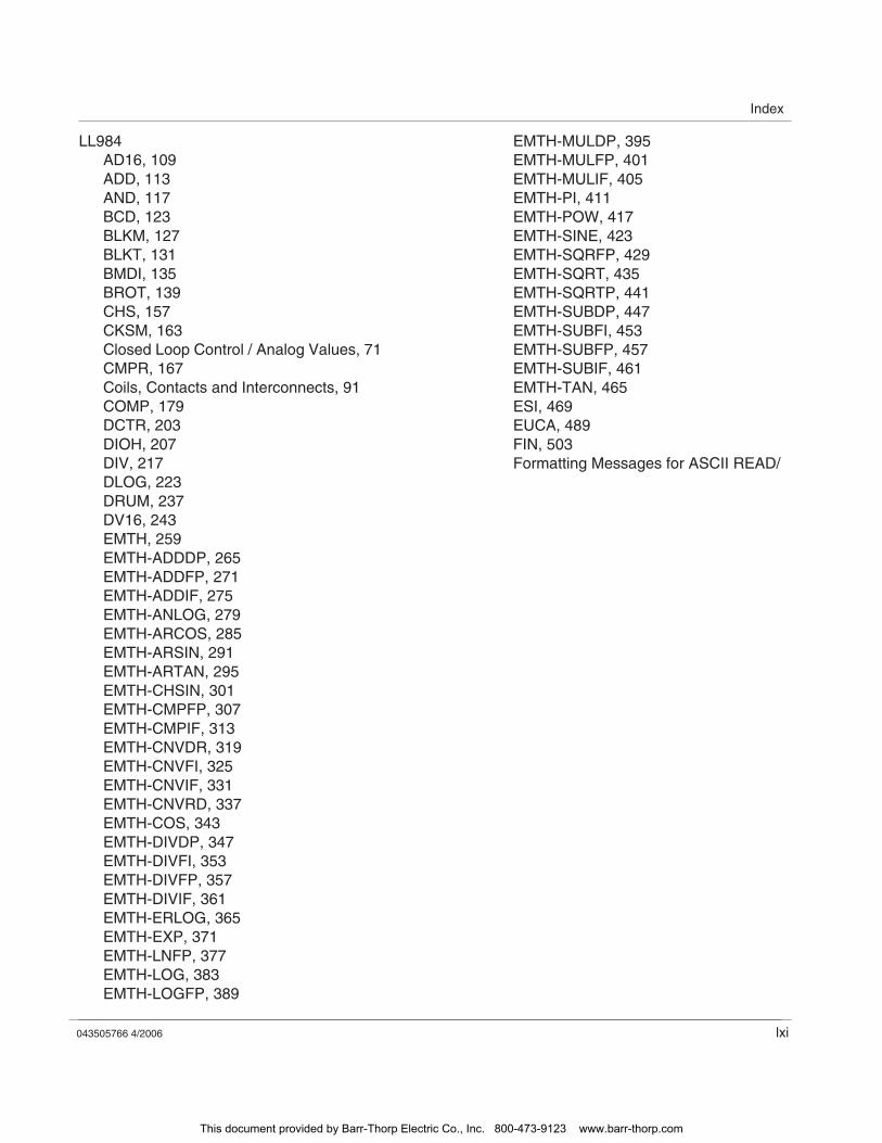
Index
043505766 4/2006 lxi
LL984AD16, 109ADD, 113AND, 117BCD, 123BLKM, 127BLKT, 131BMDI, 135BROT, 139CHS, 157CKSM, 163Closed Loop Control / Analog Values, 71CMPR, 167Coils, Contacts and Interconnects, 91COMP, 179DCTR, 203DIOH, 207DIV, 217DLOG, 223DRUM, 237DV16, 243EMTH, 259EMTH-ADDDP, 265EMTH-ADDFP, 271EMTH-ADDIF, 275EMTH-ANLOG, 279EMTH-ARCOS, 285EMTH-ARSIN, 291EMTH-ARTAN, 295EMTH-CHSIN, 301EMTH-CMPFP, 307EMTH-CMPIF, 313EMTH-CNVDR, 319EMTH-CNVFI, 325EMTH-CNVIF, 331EMTH-CNVRD, 337EMTH-COS, 343EMTH-DIVDP, 347EMTH-DIVFI, 353EMTH-DIVFP, 357EMTH-DIVIF, 361EMTH-ERLOG, 365EMTH-EXP, 371EMTH-LNFP, 377EMTH-LOG, 383EMTH-LOGFP, 389
EMTH-MULDP, 395EMTH-MULFP, 401EMTH-MULIF, 405EMTH-PI, 411EMTH-POW, 417EMTH-SINE, 423EMTH-SQRFP, 429EMTH-SQRT, 435EMTH-SQRTP, 441EMTH-SUBDP, 447EMTH-SUBFI, 453EMTH-SUBFP, 457EMTH-SUBIF, 461EMTH-TAN, 465ESI, 469EUCA, 489FIN, 503Formatting Messages for ASCII READ/
This document provided by Barr-Thorp Electric Co., Inc. 800-473-9123 www.barr-thorp.com
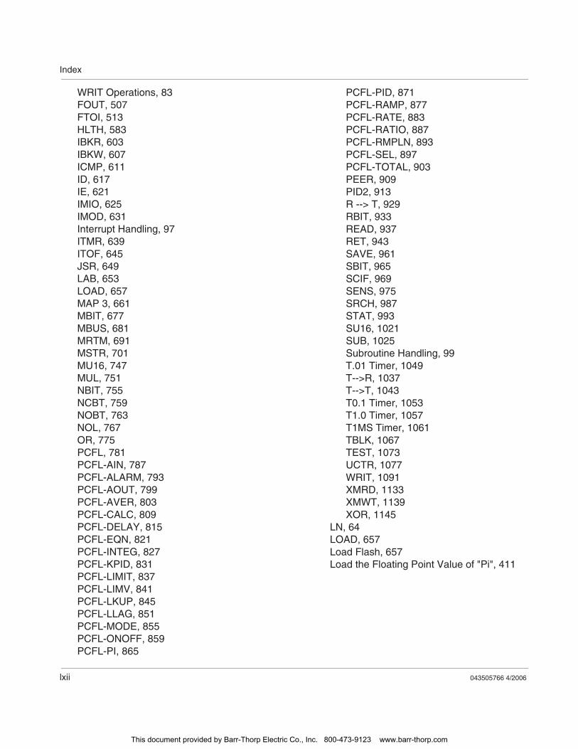
Index
lxii 043505766 4/2006
WRIT Operations, 83FOUT, 507FTOI, 513HLTH, 583IBKR, 603IBKW, 607ICMP, 611ID, 617IE, 621IMIO, 625IMOD, 631Interrupt Handling, 97ITMR, 639ITOF, 645JSR, 649LAB, 653LOAD, 657MAP 3, 661MBIT, 677MBUS, 681MRTM, 691MSTR, 701MU16, 747MUL, 751NBIT, 755NCBT, 759NOBT, 763NOL, 767OR, 775PCFL, 781PCFL-AIN, 787PCFL-ALARM, 793PCFL-AOUT, 799PCFL-AVER, 803PCFL-CALC, 809PCFL-DELAY, 815PCFL-EQN, 821PCFL-INTEG, 827PCFL-KPID, 831PCFL-LIMIT, 837PCFL-LIMV, 841PCFL-LKUP, 845PCFL-LLAG, 851PCFL-MODE, 855PCFL-ONOFF, 859PCFL-PI, 865
PCFL-PID, 871PCFL-RAMP, 877PCFL-RATE, 883PCFL-RATIO, 887PCFL-RMPLN, 893PCFL-SEL, 897PCFL-TOTAL, 903PEER, 909PID2, 913R --> T, 929RBIT, 933READ, 937RET, 943SAVE, 961SBIT, 965SCIF, 969SENS, 975SRCH, 987STAT, 993SU16, 1021SUB, 1025Subroutine Handling, 99T.01 Timer, 1049T-->R, 1037T-->T, 1043T0.1 Timer, 1053T1.0 Timer, 1057T1MS Timer, 1061TBLK, 1067TEST, 1073UCTR, 1077WRIT, 1091XMRD, 1133XMWT, 1139XOR, 1145
LN, 64LOAD, 657Load Flash, 657Load the Floating Point Value of "Pi", 411
This document provided by Barr-Thorp Electric Co., Inc. 800-473-9123 www.barr-thorp.com
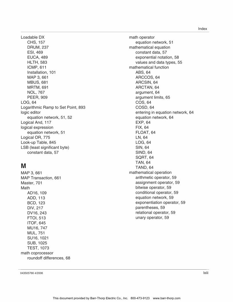
Index
043505766 4/2006 lxiii
Loadable DXCHS, 157DRUM, 237ESI, 469EUCA, 489HLTH, 583ICMP, 611Installation, 101MAP 3, 661MBUS, 681MRTM, 691NOL, 767PEER, 909
LOG, 64Logarithmic Ramp to Set Point, 893logic editor
equation network, 51, 52Logical And, 117logical expression
equation network, 51Logical OR, 775Look-up Table, 845LSB (least significant byte)
constant data, 57
MMAP 3, 661MAP Transaction, 661Master, 701Math
AD16, 109ADD, 113BCD, 123DIV, 217DV16, 243FTOI, 513ITOF, 645MU16, 747MUL, 751SU16, 1021SUB, 1025TEST, 1073
math coprocessorroundoff differences, 68
math operatorequation network, 51
mathematical equationconstant data, 57exponential notation, 58values and data types, 55
mathematical functionABS, 64ARCCOS, 64ARCSIN, 64ARCTAN, 64argument, 64argument limits, 65COS, 64COSD, 64entering in equation network, 64equation network, 64EXP, 64FIX, 64FLOAT, 64LN, 64LOG, 64SIN, 64SIND, 64SQRT, 64TAN, 64TAND, 64
mathematical operationarithmetic operator, 59assignment operator, 59bitwise operator, 59conditional operator, 59equation network, 59exponentiation operator, 59parentheses, 59relational operator, 59unary operator, 59
This document provided by Barr-Thorp Electric Co., Inc. 800-473-9123 www.barr-thorp.com
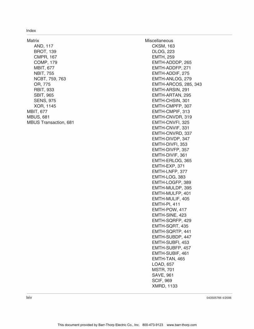
Index
lxiv 043505766 4/2006
MatrixAND, 117BROT, 139CMPR, 167COMP, 179MBIT, 677NBIT, 755NCBT, 759, 763OR, 775RBIT, 933SBIT, 965SENS, 975XOR, 1145
MBIT, 677MBUS, 681MBUS Transaction, 681
MiscellaneousCKSM, 163DLOG, 223EMTH, 259EMTH-ADDDP, 265EMTH-ADDFP, 271EMTH-ADDIF, 275EMTH-ANLOG, 279EMTH-ARCOS, 285, 343EMTH-ARSIN, 291EMTH-ARTAN, 295EMTH-CHSIN, 301EMTH-CMPFP, 307EMTH-CMPIF, 313EMTH-CNVDR, 319EMTH-CNVFI, 325EMTH-CNVIF, 331EMTH-CNVRD, 337EMTH-DIVDP, 347EMTH-DIVFI, 353EMTH-DIVFP, 357EMTH-DIVIF, 361EMTH-ERLOG, 365EMTH-EXP, 371EMTH-LNFP, 377EMTH-LOG, 383EMTH-LOGFP, 389EMTH-MULDP, 395EMTH-MULFP, 401EMTH-MULIF, 405EMTH-PI, 411EMTH-POW, 417EMTH-SINE, 423EMTH-SQRFP, 429EMTH-SQRT, 435EMTH-SQRTP, 441EMTH-SUBDP, 447EMTH-SUBFI, 453EMTH-SUBFP, 457EMTH-SUBIF, 461EMTH-TAN, 465LOAD, 657MSTR, 701SAVE, 961SCIF, 969XMRD, 1133
This document provided by Barr-Thorp Electric Co., Inc. 800-473-9123 www.barr-thorp.com
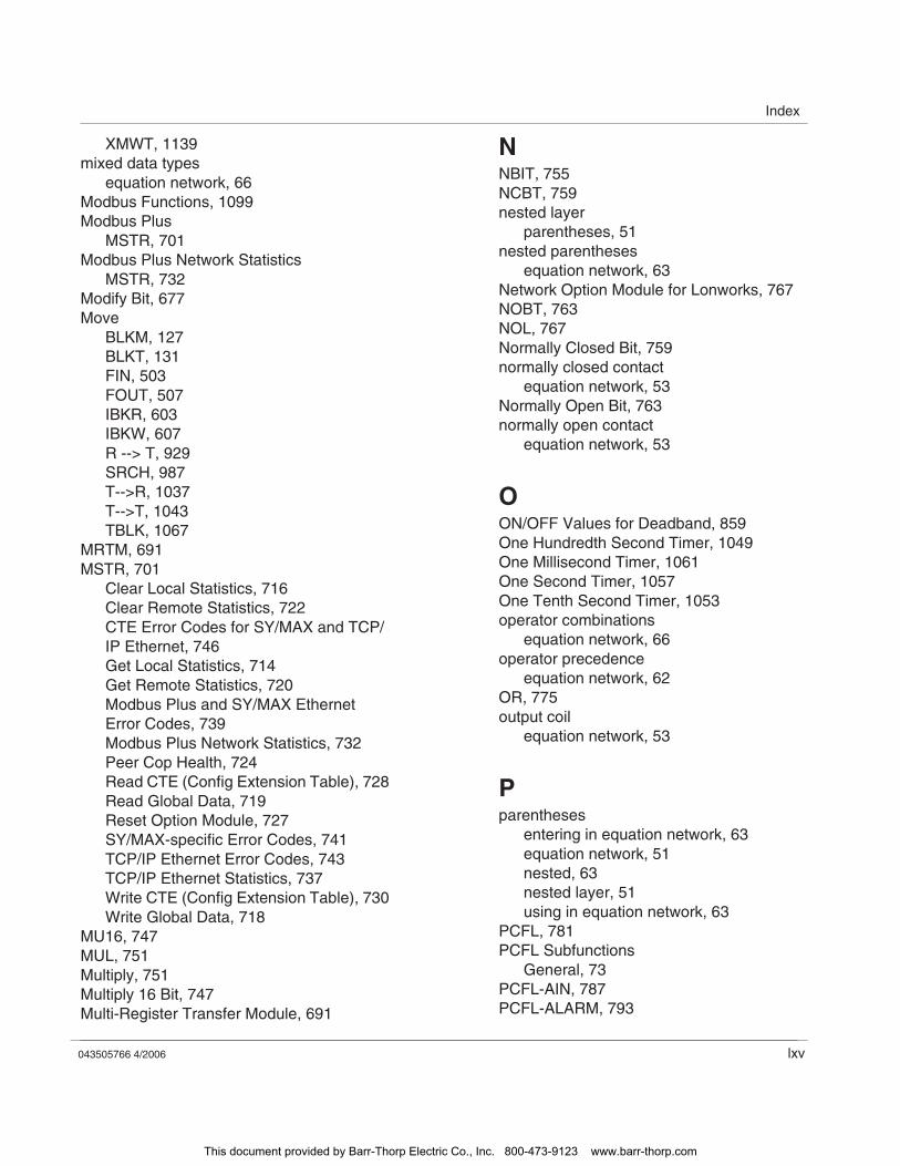
Index
043505766 4/2006 lxv
XMWT, 1139mixed data types
equation network, 66Modbus Functions, 1099Modbus Plus
MSTR, 701Modbus Plus Network Statistics
MSTR, 732Modify Bit, 677Move
BLKM, 127BLKT, 131FIN, 503FOUT, 507IBKR, 603IBKW, 607R --> T, 929SRCH, 987T-->R, 1037T-->T, 1043TBLK, 1067
MRTM, 691MSTR, 701
Clear Local Statistics, 716Clear Remote Statistics, 722CTE Error Codes for SY/MAX and TCP/IP Ethernet, 746Get Local Statistics, 714Get Remote Statistics, 720Modbus Plus and SY/MAX Ethernet Error Codes, 739Modbus Plus Network Statistics, 732Peer Cop Health, 724Read CTE (Config Extension Table), 728Read Global Data, 719Reset Option Module, 727SY/MAX-specific Error Codes, 741TCP/IP Ethernet Error Codes, 743TCP/IP Ethernet Statistics, 737Write CTE (Config Extension Table), 730Write Global Data, 718
MU16, 747MUL, 751Multiply, 751Multiply 16 Bit, 747Multi-Register Transfer Module, 691
NNBIT, 755NCBT, 759nested layer
parentheses, 51nested parentheses
equation network, 63Network Option Module for Lonworks, 767NOBT, 763NOL, 767Normally Closed Bit, 759normally closed contact
equation network, 53Normally Open Bit, 763normally open contact
equation network, 53
OON/OFF Values for Deadband, 859One Hundredth Second Timer, 1049One Millisecond Timer, 1061One Second Timer, 1057One Tenth Second Timer, 1053operator combinations
equation network, 66operator precedence
equation network, 62OR, 775output coil
equation network, 53
Pparentheses
entering in equation network, 63equation network, 51nested, 63nested layer, 51using in equation network, 63
PCFL, 781PCFL Subfunctions
General, 73PCFL-AIN, 787PCFL-ALARM, 793
This document provided by Barr-Thorp Electric Co., Inc. 800-473-9123 www.barr-thorp.com
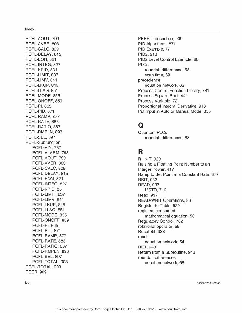
Index
lxvi 043505766 4/2006
PCFL-AOUT, 799PCFL-AVER, 803PCFL-CALC, 809PCFL-DELAY, 815PCFL-EQN, 821PCFL-INTEG, 827PCFL-KPID, 831PCFL-LIMIT, 837PCFL-LIMV, 841PCFL-LKUP, 845PCFL-LLAG, 851PCFL-MODE, 855PCFL-ONOFF, 859PCFL-PI, 865PCFL-PID, 871PCFL-RAMP, 877PCFL-RATE, 883PCFL-RATIO, 887PCFL-RMPLN, 893PCFL-SEL, 897PCFL-Subfunction
PCFL-AIN, 787PCFL-ALARM, 793PCFL-AOUT, 799PCFL-AVER, 803PCFL-CALC, 809PCFL-DELAY, 815PCFL-EQN, 821PCFL-INTEG, 827PCFL-KPID, 831PCFL-LIMIT, 837PCFL-LIMV, 841PCFL-LKUP, 845PCFL-LLAG, 851PCFL-MODE, 855PCFL-ONOFF, 859PCFL-PI, 865PCFL-PID, 871PCFL-RAMP, 877PCFL-RATE, 883PCFL-RATIO, 887PCFL-RMPLN, 893PCFL-SEL, 897PCFL-TOTAL, 903
PCFL-TOTAL, 903PEER, 909
PEER Transaction, 909PID Algorithms, 871PID Example, 77PID2, 913PID2 Level Control Example, 80PLCs
roundoff differences, 68scan time, 69
precedenceequation network, 62
Process Control Function Library, 781Process Square Root, 441Process Variable, 72Proportional Integral Derivative, 913Put Input in Auto or Manual Mode, 855
QQuantum PLCs
roundoff differences, 68
RR --> T, 929Raising a Floating Point Number to an Integer Power, 417Ramp to Set Point at a Constant Rate, 877RBIT, 933READ, 937
MSTR, 712Read, 937READ/WRIT Operations, 83Register to Table, 929registers consumed
mathematical equation, 56Regulatory Control, 782relational operator, 59Reset Bit, 933result
equation network, 54RET, 943Return from a Subroutine, 943roundoff differences
equation network, 68
This document provided by Barr-Thorp Electric Co., Inc. 800-473-9123 www.barr-thorp.com
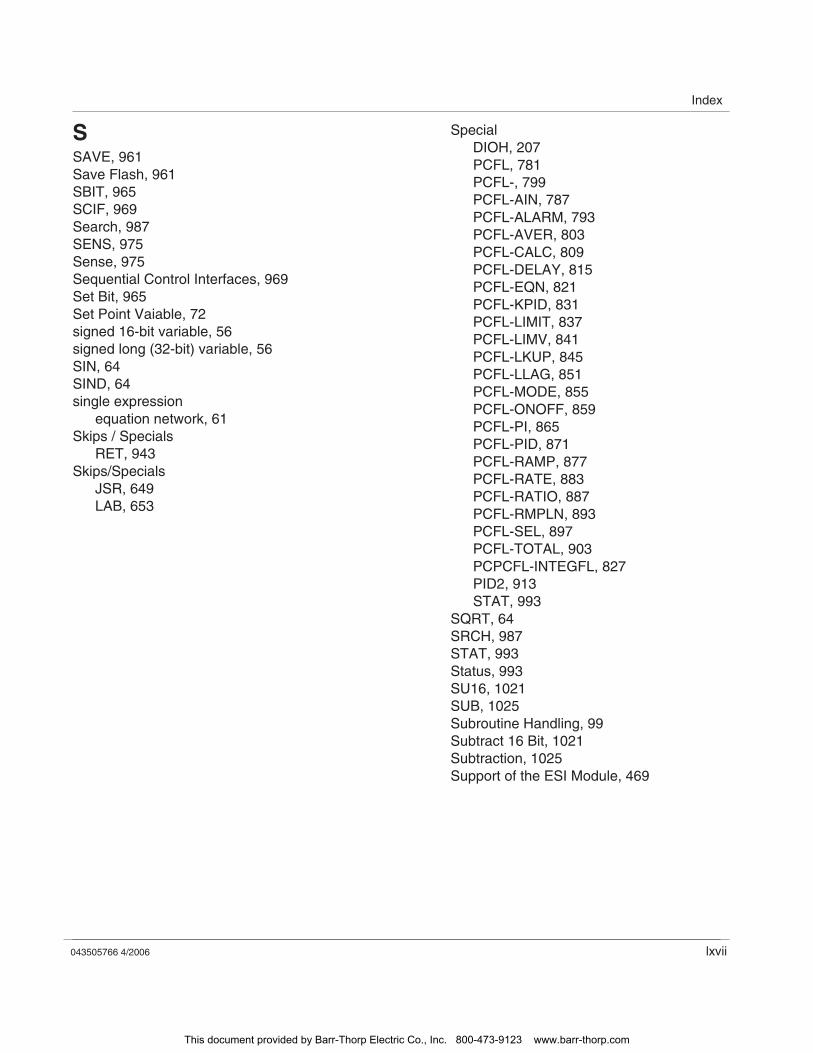
Index
043505766 4/2006 lxvii
SSAVE, 961Save Flash, 961SBIT, 965SCIF, 969Search, 987SENS, 975Sense, 975Sequential Control Interfaces, 969Set Bit, 965Set Point Vaiable, 72signed 16-bit variable, 56signed long (32-bit) variable, 56SIN, 64SIND, 64single expression
equation network, 61Skips / Specials
RET, 943Skips/Specials
JSR, 649LAB, 653
SpecialDIOH, 207PCFL, 781PCFL-, 799PCFL-AIN, 787PCFL-ALARM, 793PCFL-AVER, 803PCFL-CALC, 809PCFL-DELAY, 815PCFL-EQN, 821PCFL-KPID, 831PCFL-LIMIT, 837PCFL-LIMV, 841PCFL-LKUP, 845PCFL-LLAG, 851PCFL-MODE, 855PCFL-ONOFF, 859PCFL-PI, 865PCFL-PID, 871PCFL-RAMP, 877PCFL-RATE, 883PCFL-RATIO, 887PCFL-RMPLN, 893PCFL-SEL, 897PCFL-TOTAL, 903PCPCFL-INTEGFL, 827PID2, 913STAT, 993
SQRT, 64SRCH, 987STAT, 993Status, 993SU16, 1021SUB, 1025Subroutine Handling, 99Subtract 16 Bit, 1021Subtraction, 1025Support of the ESI Module, 469
This document provided by Barr-Thorp Electric Co., Inc. 800-473-9123 www.barr-thorp.com
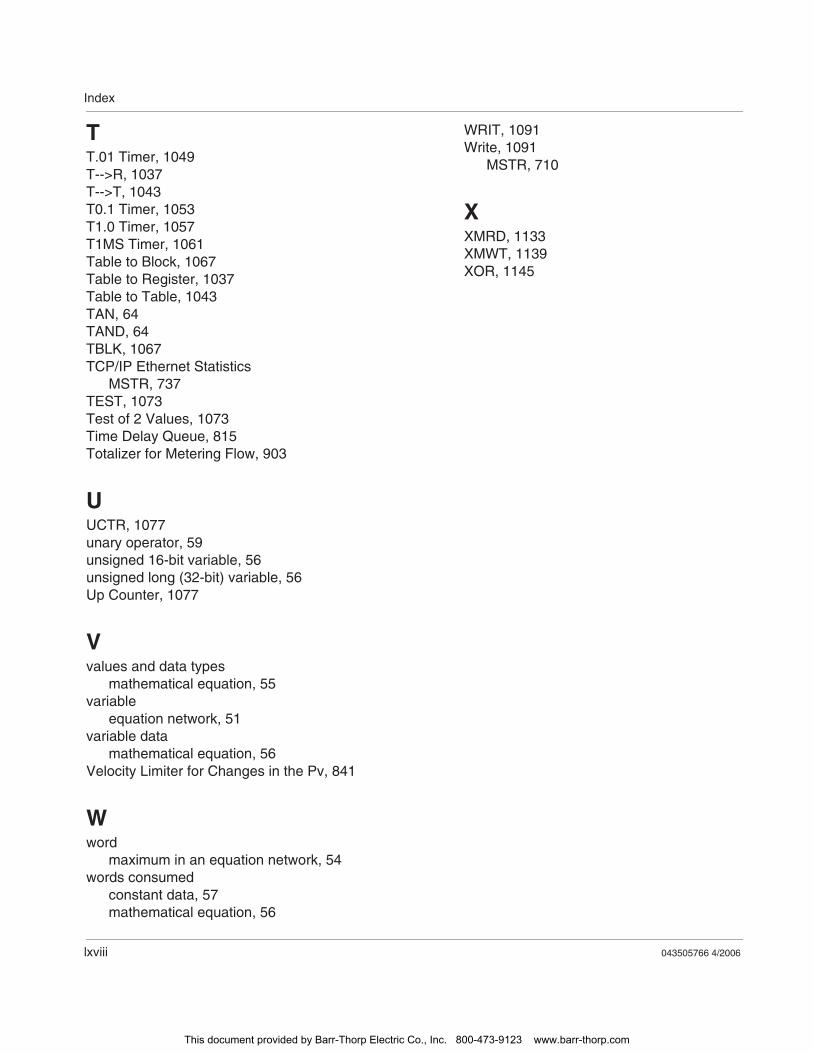
Index
lxviii 043505766 4/2006
TT.01 Timer, 1049T-->R, 1037T-->T, 1043T0.1 Timer, 1053T1.0 Timer, 1057T1MS Timer, 1061Table to Block, 1067Table to Register, 1037Table to Table, 1043TAN, 64TAND, 64TBLK, 1067TCP/IP Ethernet Statistics
MSTR, 737TEST, 1073Test of 2 Values, 1073Time Delay Queue, 815Totalizer for Metering Flow, 903
UUCTR, 1077unary operator, 59unsigned 16-bit variable, 56unsigned long (32-bit) variable, 56Up Counter, 1077
Vvalues and data types
mathematical equation, 55variable
equation network, 51variable data
mathematical equation, 56Velocity Limiter for Changes in the Pv, 841
Wword
maximum in an equation network, 54words consumed
constant data, 57mathematical equation, 56
WRIT, 1091Write, 1091
MSTR, 710
XXMRD, 1133XMWT, 1139XOR, 1145
This document provided by Barr-Thorp Electric Co., Inc. 800-473-9123 www.barr-thorp.com