Embed Size (px)
Citation preview
Modicon M262 Logic/Motion Controller
EIO0000003667 05/2019
EIO
0000
0036
67.0
0
www.schneider-electric.com
Modicon M262 Logic/Motion ControllerSystem Functions and VariablesSystem Library Guide05/2019
The information provided in this documentation contains general descriptions and/or technical characteristics of the performance of the products contained herein. This documentation is not intended as a substitute for and is not to be used for determining suitability or reliability of these products for specific user applications. It is the duty of any such user or integrator to perform the appropriate and complete risk analysis, evaluation and testing of the products with respect to the relevant specific application or use thereof. Neither Schneider Electric nor any of its affiliates or subsidiaries shall be responsible or liable for misuse of the information contained herein. If you have any suggestions for improvements or amendments or have found errors in this publication, please notify us. You agree not to reproduce, other than for your own personal, noncommercial use, all or part of this document on any medium whatsoever without permission of Schneider Electric, given in writing. You also agree not to establish any hypertext links to this document or its content. Schneider Electric does not grant any right or license for the personal and noncommercial use of the document or its content, except for a non-exclusive license to consult it on an "as is" basis, at your own risk. All other rights are reserved.All pertinent state, regional, and local safety regulations must be observed when installing and using this product. For reasons of safety and to help ensure compliance with documented system data, only the manufacturer should perform repairs to components.When devices are used for applications with technical safety requirements, the relevant instructions must be followed. Failure to use Schneider Electric software or approved software with our hardware products may result in injury, harm, or improper operating results.Failure to observe this information can result in injury or equipment damage.© 2019 Schneider Electric. All rights reserved.
2 EIO0000003667 05/2019
Table of Contents
Safety Information. . . . . . . . . . . . . . . . . . . . . . . . . . . . . . 7About the Book . . . . . . . . . . . . . . . . . . . . . . . . . . . . . . . . 9
Part I M262 PLCSystem. . . . . . . . . . . . . . . . . . . . . . . . . . . 15Chapter 1 M262 System Variables . . . . . . . . . . . . . . . . . . . . . . . . . 17
1.1 System Variables: Definition and Use . . . . . . . . . . . . . . . . . . . . . . . . . 18Understanding System Variables . . . . . . . . . . . . . . . . . . . . . . . . . . . . 19Using System Variables . . . . . . . . . . . . . . . . . . . . . . . . . . . . . . . . . . . 21
1.2 PLC_R and PLC_W Structures . . . . . . . . . . . . . . . . . . . . . . . . . . . . . . 23PLC_R: Controller Read-Only System Variables . . . . . . . . . . . . . . . . . 24PLC_W: Controller Read/Write System Variables . . . . . . . . . . . . . . . . 29
1.3 ETH_R and ETH_W Structures . . . . . . . . . . . . . . . . . . . . . . . . . . . . . . 30ETH_R: Ethernet Port Read-Only System Variables . . . . . . . . . . . . . 31ETH_W: Ethernet Port Read/Write System Variables. . . . . . . . . . . . . . 36
Chapter 2 M262 System Functions . . . . . . . . . . . . . . . . . . . . . . . . . 372.1 M262 Read Functions . . . . . . . . . . . . . . . . . . . . . . . . . . . . . . . . . . . . . 38
GetImmediateFastInput: Read Input of an Embedded Expert I/O 39GetRtc: Get Real Time Clock. . . . . . . . . . . . . . . . . . . . . . . . . . . . . . . 41IsFirstMastColdCycle: Indicate if this Cycle is the First MAST Cold Start Cycle. . . . . . . . . . . . . . . . . . . . . . . . . . . . . . . . . . . . . . . . . . 42IsFirstMastCycle: Indicate if this Cycle is the First MAST Cycle . 43IsFirstMastWarmCycle: Indicate if this Cycle is the First MAST Warm Start Cycle . . . . . . . . . . . . . . . . . . . . . . . . . . . . . . . . . . . . . . . . 45GetExternalEventValue: Get Current Value of an External Event 46
2.2 M262 Write Functions . . . . . . . . . . . . . . . . . . . . . . . . . . . . . . . . . . . . . 47PhysicalWriteFastOutputs: Write Fast Output of an Embedded Expert I/O . . . . . . . . . . . . . . . . . . . . . . . . . . . . . . . . . . . . . . . . . . . . . . 47
2.3 M262 User Functions . . . . . . . . . . . . . . . . . . . . . . . . . . . . . . . . . . . . . 49FB_CheckAllowedControllerMacAddress: Check If MAC Address Allowed by Controller . . . . . . . . . . . . . . . . . . . . . . . . . . . . . . 50FB_ControlClone: Clone the Controller . . . . . . . . . . . . . . . . . . . . . 51DataFileCopy: Copy File Commands . . . . . . . . . . . . . . . . . . . . . . . 52ExecuteScript: Run Script Commands . . . . . . . . . . . . . . . . . . . . . 55
EIO0000003667 05/2019 3
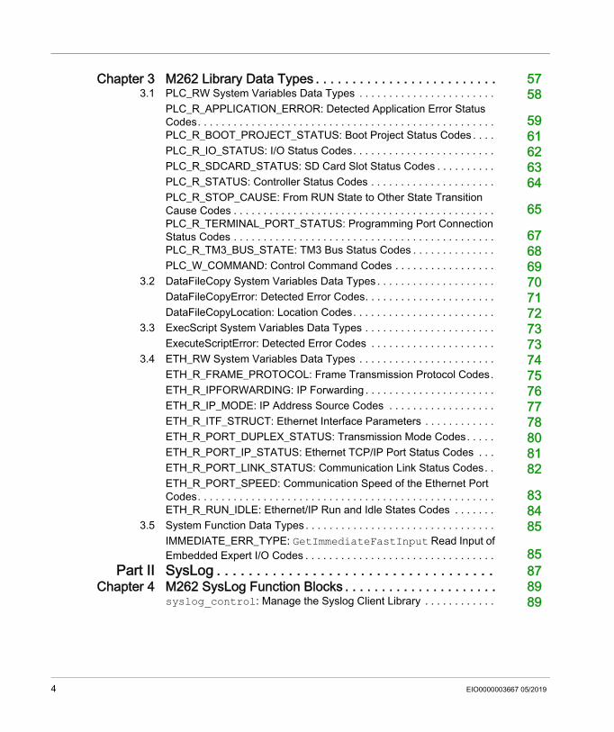
Chapter 3 M262 Library Data Types . . . . . . . . . . . . . . . . . . . . . . . . . 573.1 PLC_RW System Variables Data Types . . . . . . . . . . . . . . . . . . . . . . . 58
PLC_R_APPLICATION_ERROR: Detected Application Error Status Codes. . . . . . . . . . . . . . . . . . . . . . . . . . . . . . . . . . . . . . . . . . . . . . . . . . 59PLC_R_BOOT_PROJECT_STATUS: Boot Project Status Codes . . . . 61PLC_R_IO_STATUS: I/O Status Codes. . . . . . . . . . . . . . . . . . . . . . . . 62PLC_R_SDCARD_STATUS: SD Card Slot Status Codes . . . . . . . . . . 63PLC_R_STATUS: Controller Status Codes . . . . . . . . . . . . . . . . . . . . . 64PLC_R_STOP_CAUSE: From RUN State to Other State Transition Cause Codes . . . . . . . . . . . . . . . . . . . . . . . . . . . . . . . . . . . . . . . . . . . . 65PLC_R_TERMINAL_PORT_STATUS: Programming Port Connection Status Codes . . . . . . . . . . . . . . . . . . . . . . . . . . . . . . . . . . . . . . . . . . . . 67PLC_R_TM3_BUS_STATE: TM3 Bus Status Codes . . . . . . . . . . . . . . 68PLC_W_COMMAND: Control Command Codes . . . . . . . . . . . . . . . . . 69
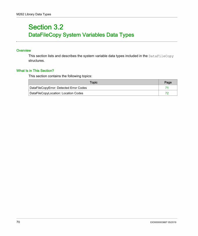
3.2 DataFileCopy System Variables Data Types . . . . . . . . . . . . . . . . . . . . 70DataFileCopyError: Detected Error Codes. . . . . . . . . . . . . . . . . . . . . . 71DataFileCopyLocation: Location Codes. . . . . . . . . . . . . . . . . . . . . . . . 72
3.3 ExecScript System Variables Data Types . . . . . . . . . . . . . . . . . . . . . . 73ExecuteScriptError: Detected Error Codes . . . . . . . . . . . . . . . . . . . . . 73
3.4 ETH_RW System Variables Data Types . . . . . . . . . . . . . . . . . . . . . . . 74ETH_R_FRAME_PROTOCOL: Frame Transmission Protocol Codes. 75ETH_R_IPFORWARDING: IP Forwarding . . . . . . . . . . . . . . . . . . . . . . 76ETH_R_IP_MODE: IP Address Source Codes . . . . . . . . . . . . . . . . . . 77ETH_R_ITF_STRUCT: Ethernet Interface Parameters . . . . . . . . . . . . 78ETH_R_PORT_DUPLEX_STATUS: Transmission Mode Codes. . . . . 80ETH_R_PORT_IP_STATUS: Ethernet TCP/IP Port Status Codes . . . 81ETH_R_PORT_LINK_STATUS: Communication Link Status Codes. . 82ETH_R_PORT_SPEED: Communication Speed of the Ethernet Port Codes. . . . . . . . . . . . . . . . . . . . . . . . . . . . . . . . . . . . . . . . . . . . . . . . . . 83ETH_R_RUN_IDLE: Ethernet/IP Run and Idle States Codes . . . . . . . 84
3.5 System Function Data Types . . . . . . . . . . . . . . . . . . . . . . . . . . . . . . . . 85IMMEDIATE_ERR_TYPE: GetImmediateFastInput Read Input of Embedded Expert I/O Codes . . . . . . . . . . . . . . . . . . . . . . . . . . . . . . . . 85
Part II SysLog . . . . . . . . . . . . . . . . . . . . . . . . . . . . . . . . . . . 87Chapter 4 M262 SysLog Function Blocks . . . . . . . . . . . . . . . . . . . . . 89
syslog_control: Manage the Syslog Client Library . . . . . . . . . . . . 89
4 EIO0000003667 05/2019
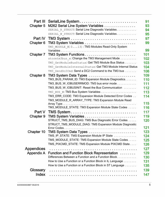
Part III SerialLine System. . . . . . . . . . . . . . . . . . . . . . . . . . . 91Chapter 5 M262 Serial Line System Variables . . . . . . . . . . . . . . . . 93
SERIAL_R_STRUCT: Serial Line Diagnostic Variables . . . . . . . . . . . . 94SERIAL_W_STRUCT: Serial Line Diagnostic Variables . . . . . . . . . . . . 95
Part IV TM3 System . . . . . . . . . . . . . . . . . . . . . . . . . . . . . . . 97Chapter 6 TM3 System Variables . . . . . . . . . . . . . . . . . . . . . . . . . . 99
TM3_MODULE_R[0...13]: TM3 Modules Read-Only System Variables . . . . . . . . . . . . . . . . . . . . . . . . . . . . . . . . . . . . . . . . . . . . . . . 99
Chapter 7 TM3 System Functions . . . . . . . . . . . . . . . . . . . . . . . . . . 101storetm3bus_w: Change the TM3 Management Mode . . . . . . . . . . 102TM3_GetModuleBusStatus: Get TM3 Module Bus Status . . . . . . . 103TM3_GetModuleInternalStatus: Get TM3 Module Internal Status 104TM3_SendDc2Cmd: Send a DC2 Command to the TM3 bus . . . . . . . 106
Chapter 8 TM3 System Data Types . . . . . . . . . . . . . . . . . . . . . . . . 109TM3_BUS_PARAM_ID: TM3 Expansion Module Diagnostics . . . . . . . 110TM3_BUS_W_IOBUSERRMOD: TM3 bus error mode . . . . . . . . . . . . 111TM3_BUS_W_IOBUSINIT: Reset the Bus Communication . . . . . . . . 112TM3_BUS_W: TM3 Bus System Variables . . . . . . . . . . . . . . . . . . . . . . 113TM3_ERR_CODE: TM3 Expansion Module Detected Error Codes . . 114TM3_MODULE_R_ARRAY_TYPE: TM3 Expansion Module Read Array Type . . . . . . . . . . . . . . . . . . . . . . . . . . . . . . . . . . . . . . . . . . . . . . 115TM3_MODULE_STATE: TM3 Expansion Module State Codes . . . . . 116
Part V TMS System . . . . . . . . . . . . . . . . . . . . . . . . . . . . . . . 117Chapter 9 TMS System Variables . . . . . . . . . . . . . . . . . . . . . . . . . . 119
STRUCT_TMS_BUS_DIAG: TMS Bus Diagnostic Error Codes . . . . . 120STRUCT_TMS_MODULE_DIAG: TMS Expansion Module Diagnostic Error Codes . . . . . . . . . . . . . . . . . . . . . . . . . . . . . . . . . . . . . . . . . . . . . 121
Chapter 10 TMS System Data Types . . . . . . . . . . . . . . . . . . . . . . . . 123TMS_IP_STATE: TMS Expansion Module IP State . . . . . . . . . . . . . . 124TMS_MODULE_STATE: TMS Expansion Module State Codes . . . . . 125TMS_PIXCMD_STATE: TMS Expansion Module PIXCMD State . . . . 126
Appendices . . . . . . . . . . . . . . . . . . . . . . . . . . . . . . . . . . . . . . . . . 127Appendix A Function and Function Block Representation . . . . . . . . 129
Differences Between a Function and a Function Block . . . . . . . . . . . . 130How to Use a Function or a Function Block in IL Language . . . . . . . . 131How to Use a Function or a Function Block in ST Language . . . . . . . 135
Glossary . . . . . . . . . . . . . . . . . . . . . . . . . . . . . . . . . . . . . . . . . 139Index . . . . . . . . . . . . . . . . . . . . . . . . . . . . . . . . . . . . . . . . . 147
EIO0000003667 05/2019 5

6 EIO0000003667 05/2019
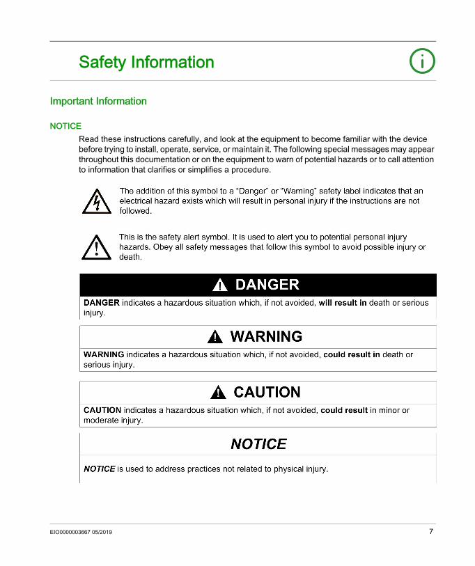
Safety Information
Important Information
NOTICERead these instructions carefully, and look at the equipment to become familiar with the device before trying to install, operate, service, or maintain it. The following special messages may appear throughout this documentation or on the equipment to warn of potential hazards or to call attention to information that clarifies or simplifies a procedure.
EIO0000003667 05/2019 7
PLEASE NOTEElectrical equipment should be installed, operated, serviced, and maintained only by qualified personnel. No responsibility is assumed by Schneider Electric for any consequences arising out of the use of this material.A qualified person is one who has skills and knowledge related to the construction and operation of electrical equipment and its installation, and has received safety training to recognize and avoid the hazards involved.
8 EIO0000003667 05/2019
About the Book
At a Glance
Document ScopeThis document will acquaint you with the system functions and variables offered within the Modicon M262 Logic/Motion Controller. The M262 System library contains functions and variables to get information from and send commands to the controller system.This document describes the data type functions and variables of the following M262 system libraries: M262 PLCSystem Syslog Serial Line System TM3 System TMS SystemThe following knowledge is required: Basic information on the functionality, structure, and configuration of the M262 Logic/Motion
Controller. Programming in the FBD, LD, ST, IL, or CFC language. System variables (global variables).
Validity Note
This document has been updated for the release of EcoStruxureTM Machine Expert V1.1.
EIO0000003667 05/2019 9
Related Documents
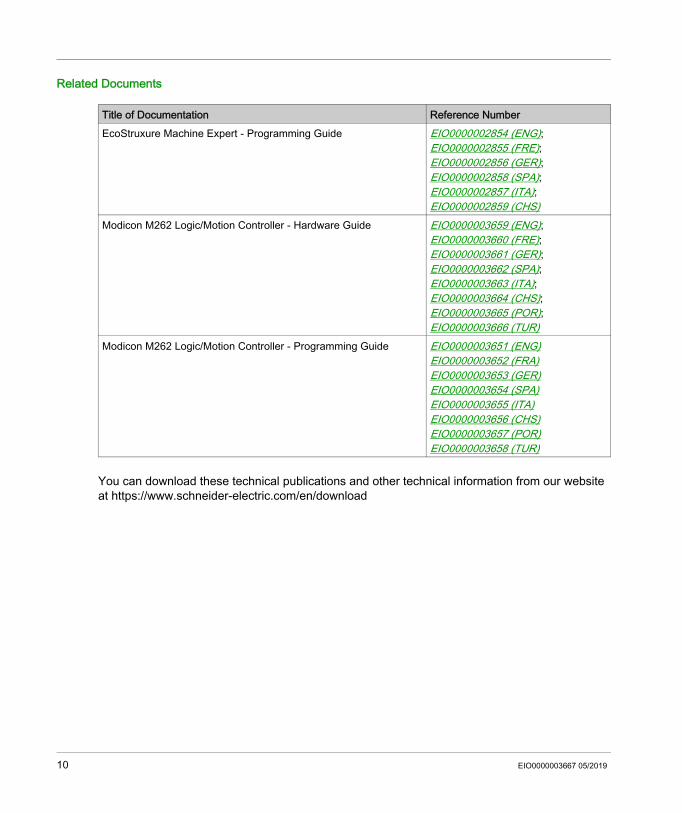
You can download these technical publications and other technical information from our website at https://www.schneider-electric.com/en/download
Title of Documentation Reference NumberEcoStruxure Machine Expert - Programming Guide EIO0000002854 (ENG);
EIO0000002855 (FRE); EIO0000002856 (GER); EIO0000002858 (SPA); EIO0000002857 (ITA); EIO0000002859 (CHS)
Modicon M262 Logic/Motion Controller - Hardware Guide EIO0000003659 (ENG); EIO0000003660 (FRE); EIO0000003661 (GER); EIO0000003662 (SPA); EIO0000003663 (ITA); EIO0000003664 (CHS); EIO0000003665 (POR); EIO0000003666 (TUR)
Modicon M262 Logic/Motion Controller - Programming Guide EIO0000003651 (ENG)EIO0000003652 (FRA)EIO0000003653 (GER)EIO0000003654 (SPA)EIO0000003655 (ITA)EIO0000003656 (CHS)EIO0000003657 (POR)EIO0000003658 (TUR)
10 EIO0000003667 05/2019
Product Related Information
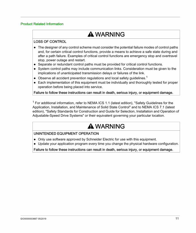
1 For additional information, refer to NEMA ICS 1.1 (latest edition), "Safety Guidelines for the Application, Installation, and Maintenance of Solid State Control" and to NEMA ICS 7.1 (latest edition), "Safety Standards for Construction and Guide for Selection, Installation and Operation of Adjustable-Speed Drive Systems" or their equivalent governing your particular location.
WARNINGLOSS OF CONTROL The designer of any control scheme must consider the potential failure modes of control paths
and, for certain critical control functions, provide a means to achieve a safe state during and after a path failure. Examples of critical control functions are emergency stop and overtravel stop, power outage and restart.
Separate or redundant control paths must be provided for critical control functions. System control paths may include communication links. Consideration must be given to the
implications of unanticipated transmission delays or failures of the link. Observe all accident prevention regulations and local safety guidelines.1 Each implementation of this equipment must be individually and thoroughly tested for proper
operation before being placed into service.Failure to follow these instructions can result in death, serious injury, or equipment damage.
WARNINGUNINTENDED EQUIPMENT OPERATION Only use software approved by Schneider Electric for use with this equipment. Update your application program every time you change the physical hardware configuration.Failure to follow these instructions can result in death, serious injury, or equipment damage.
EIO0000003667 05/2019 11
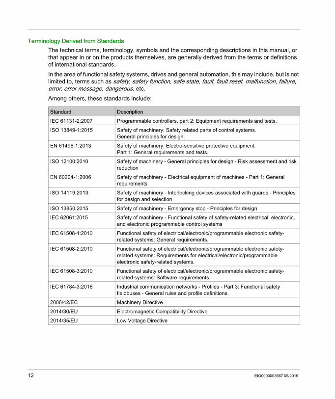
Terminology Derived from StandardsThe technical terms, terminology, symbols and the corresponding descriptions in this manual, or that appear in or on the products themselves, are generally derived from the terms or definitions of international standards.In the area of functional safety systems, drives and general automation, this may include, but is not limited to, terms such as safety, safety function, safe state, fault, fault reset, malfunction, failure, error, error message, dangerous, etc.Among others, these standards include:
Standard DescriptionIEC 61131-2:2007 Programmable controllers, part 2: Equipment requirements and tests.ISO 13849-1:2015 Safety of machinery: Safety related parts of control systems.
General principles for design.EN 61496-1:2013 Safety of machinery: Electro-sensitive protective equipment.
Part 1: General requirements and tests.ISO 12100:2010 Safety of machinery - General principles for design - Risk assessment and risk
reductionEN 60204-1:2006 Safety of machinery - Electrical equipment of machines - Part 1: General
requirementsISO 14119:2013 Safety of machinery - Interlocking devices associated with guards - Principles
for design and selectionISO 13850:2015 Safety of machinery - Emergency stop - Principles for designIEC 62061:2015 Safety of machinery - Functional safety of safety-related electrical, electronic,
and electronic programmable control systemsIEC 61508-1:2010 Functional safety of electrical/electronic/programmable electronic safety-
related systems: General requirements.IEC 61508-2:2010 Functional safety of electrical/electronic/programmable electronic safety-
related systems: Requirements for electrical/electronic/programmable electronic safety-related systems.
IEC 61508-3:2010 Functional safety of electrical/electronic/programmable electronic safety-related systems: Software requirements.
IEC 61784-3:2016 Industrial communication networks - Profiles - Part 3: Functional safety fieldbuses - General rules and profile definitions.
2006/42/EC Machinery Directive2014/30/EU Electromagnetic Compatibility Directive2014/35/EU Low Voltage Directive
12 EIO0000003667 05/2019
In addition, terms used in the present document may tangentially be used as they are derived from other standards such as:
Finally, the term zone of operation may be used in conjunction with the description of specific hazards, and is defined as it is for a hazard zone or danger zone in the Machinery Directive (2006/42/EC) and ISO 12100:2010.NOTE: The aforementioned standards may or may not apply to the specific products cited in the present documentation. For more information concerning the individual standards applicable to the products described herein, see the characteristics tables for those product references.
Standard DescriptionIEC 60034 series Rotating electrical machinesIEC 61800 series Adjustable speed electrical power drive systemsIEC 61158 series Digital data communications for measurement and control – Fieldbus for use in
industrial control systems
EIO0000003667 05/2019 13

14 EIO0000003667 05/2019
Modicon M262 Logic/Motion ControllerM262 PLCSystemEIO0000003667 05/2019
M262 PLCSystem
Part IM262 PLCSystem
IntroductionThis part describes the M262 PLCSystem Library.
What Is in This Part?This part contains the following chapters:
Chapter Chapter Name Page1 M262 System Variables 172 M262 System Functions 373 M262 Library Data Types 57
EIO0000003667 05/2019 15
M262 PLCSystem
16 EIO0000003667 05/2019
Modicon M262 Logic/Motion ControllerM262 System VariablesEIO0000003667 05/2019
M262 System Variables
Chapter 1M262 System Variables
OverviewThis chapter: gives an introduction to the system variables (see page 18) describes the system variables (see page 24) included with the M262 PLCSystem library
What Is in This Chapter?This chapter contains the following sections:
Section Topic Page1.1 System Variables: Definition and Use 181.2 PLC_R and PLC_W Structures 231.3 ETH_R and ETH_W Structures 30
EIO0000003667 05/2019 17
M262 System Variables
System Variables: Definition and Use
Section 1.1System Variables: Definition and Use
OverviewThis section defines system variables and how to implement them in the Modicon M262 Logic/Motion Controller.
What Is in This Section?This section contains the following topics:
Topic PageUnderstanding System Variables 19Using System Variables 21
18 EIO0000003667 05/2019
M262 System Variables
Understanding System Variables
IntroductionThis section describes how system variables are implemented. System variables: allow you to access general system information, perform system diagnostics, and command
simple actions. are structured variables conforming to IEC 61131-3 definitions and naming conventions. You
can access the system variables using the IEC symbolic name PLC_GVL. Some of the PLC_GVL variables are read-only (for example, PLC_R) and some are read/write (for example, PLC_W).
are automatically declared as global variables. They have system-wide scope and can be accessed by any Program Organization Unit (POU) in any task.
Naming ConventionThe system variables are identified by: a structure name that represents the category of system variable. For example, PLC_R
represents a structure name of read-only variables used for the controller diagnostic. a set of component names that identifies the purpose of the variable. For example,
i_wVendorID represents the controller vendor ID.
You can access the system variables by typing the structure name of the variables followed by the name of the component.Here is an example of system variable implementation:VAR myCtr_Serial : DWORD; myCtr_ID : DWORD; myCtr_FramesRx : UDINT;END_VAR
myCtr_Serial := PLC_GVL.PLC_R.i_dwSerialNumber;myCtr_ID := PLC_GVL.PLC.R.i_wVendorID;myCtr_FramesRx := SERIAL_R[0].i_udiFramesReceivedOK
NOTE: The fully-qualified name of the system variable in the example above is PLC_GVL.PLC.R. The PLC_GVL is implicit when declaring a variable using the Input Assistant, but it may also be entered in full. Good programming practice often dictates the use of the fully-qualified variable name in declarations.
EIO0000003667 05/2019 19
M262 System Variables
System Variables Location2 kinds of system variables are defined for use when programming the controller: located variables unlocated variablesThe located variables: are accessible through Modbus TCP, Modbus serial, and EtherNet/IP requests both in
RUNNING and STOPPED states. are used in EcoStruxure Machine Expert programs according to the
structure_name.component_name convention explained previously. %MW addresses from 0 to 59999 can be accessed directly. Addresses greater than this are considered out of range by EcoStruxure Machine Expert and can only be accessed through the structure_name.component_name convention.
The unlocated variables: are not physically located in the %MW area. are not accessible through any fieldbus or network requests unless you locate them in the
relocation table, and only then these variables can be accessed in RUNNING and STOPPED states. The relocation table uses the following dynamic %MW areas: %MW60200 to %MW61999 for read-only variables %MW62200 to %MW63999 for read/write variables
are used in EcoStruxure Machine Expert programs according to the structure_name.component_name convention explained previously.
20 EIO0000003667 05/2019
M262 System Variables
Using System Variables
IntroductionThis section describes the steps required to program and to use system variables in EcoStruxure Machine Expert.System variables are global in scope, and you can use them in all the Program Organization Units (POUs) of the application.System variables do not need to be declared in the Global Variable List (GVL). They are automatically declared from the controller system library.
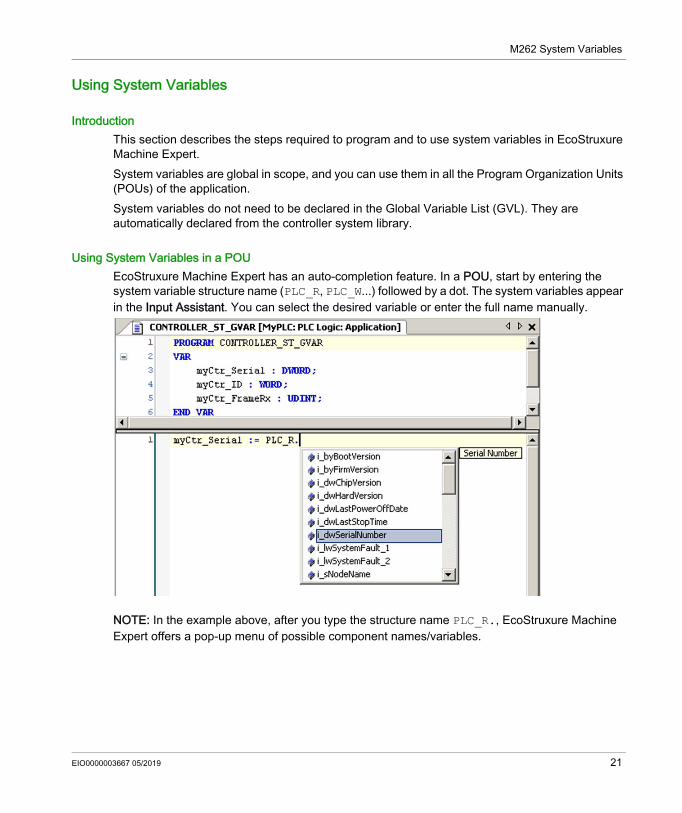
Using System Variables in a POUEcoStruxure Machine Expert has an auto-completion feature. In a POU, start by entering the system variable structure name (PLC_R, PLC_W...) followed by a dot. The system variables appear in the Input Assistant. You can select the desired variable or enter the full name manually.
NOTE: In the example above, after you type the structure name PLC_R., EcoStruxure Machine Expert offers a pop-up menu of possible component names/variables.
EIO0000003667 05/2019 21
M262 System Variables
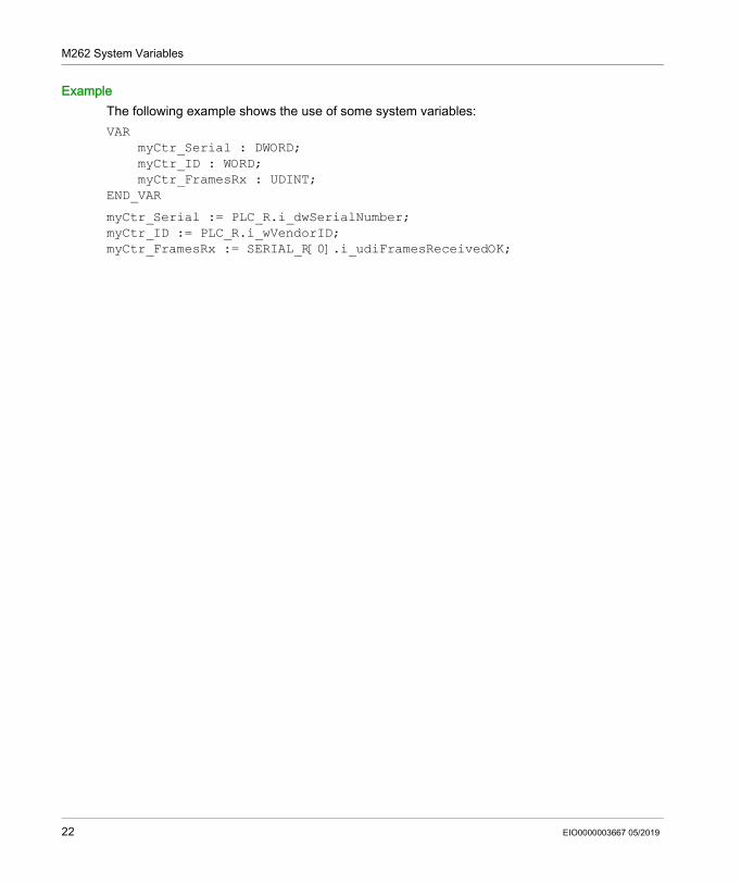
ExampleThe following example shows the use of some system variables:VAR myCtr_Serial : DWORD; myCtr_ID : WORD; myCtr_FramesRx : UDINT;END_VAR
myCtr_Serial := PLC_R.i_dwSerialNumber;myCtr_ID := PLC_R.i_wVendorID;myCtr_FramesRx := SERIAL_R[0].i_udiFramesReceivedOK;
22 EIO0000003667 05/2019
M262 System Variables
PLC_R and PLC_W Structures
Section 1.2PLC_R and PLC_W Structures
OverviewThis section lists and describes the different system variables included in the PLC_R and PLC_W structures.
What Is in This Section?This section contains the following topics:
Topic PagePLC_R: Controller Read-Only System Variables 24
PLC_W: Controller Read/Write System Variables 29
EIO0000003667 05/2019 23
M262 System Variables
PLC_R: Controller Read-Only System Variables
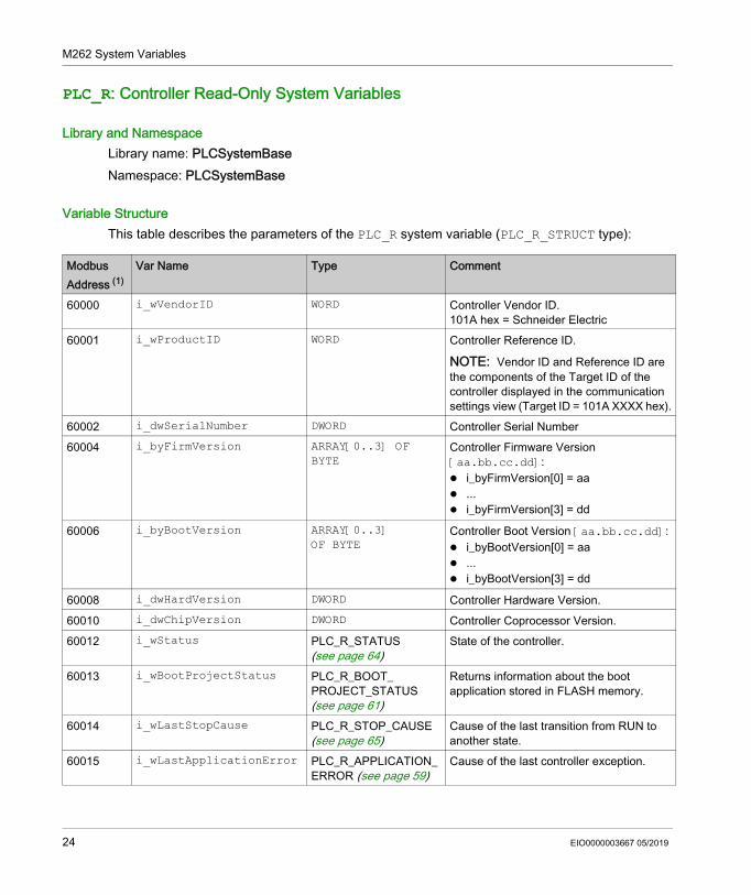
Library and NamespaceLibrary name: PLCSystemBaseNamespace: PLCSystemBase
Variable StructureThis table describes the parameters of the PLC_R system variable (PLC_R_STRUCT type):
Modbus Address (1)
Var Name Type Comment
60000 i_wVendorID WORD Controller Vendor ID.101A hex = Schneider Electric
60001 i_wProductID WORD Controller Reference ID.
NOTE: Vendor ID and Reference ID are the components of the Target ID of the controller displayed in the communication settings view (Target ID = 101A XXXX hex).
60002 i_dwSerialNumber DWORD Controller Serial Number60004 i_byFirmVersion ARRAY[0..3] OF
BYTEController Firmware Version [aa.bb.cc.dd]: i_byFirmVersion[0] = aa ... i_byFirmVersion[3] = dd
60006 i_byBootVersion ARRAY[0..3] OF BYTE
Controller Boot Version [aa.bb.cc.dd]: i_byBootVersion[0] = aa ... i_byBootVersion[3] = dd
60008 i_dwHardVersion DWORD Controller Hardware Version.60010 i_dwChipVersion DWORD Controller Coprocessor Version.60012 i_wStatus PLC_R_STATUS
(see page 64)State of the controller.
60013 i_wBootProjectStatus PLC_R_BOOT_ PROJECT_STATUS (see page 61)
Returns information about the boot application stored in FLASH memory.
60014 i_wLastStopCause PLC_R_STOP_CAUSE (see page 65)
Cause of the last transition from RUN to another state.
60015 i_wLastApplicationError PLC_R_APPLICATION_ERROR (see page 59)
Cause of the last controller exception.
24 EIO0000003667 05/2019
M262 System Variables
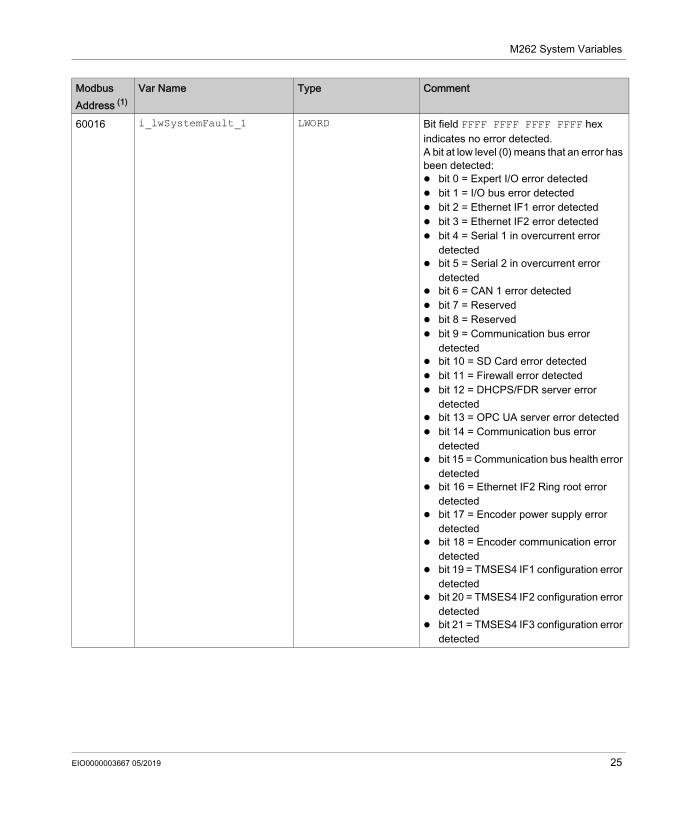
60016 i_lwSystemFault_1 LWORD Bit field FFFF FFFF FFFF FFFF hex indicates no error detected.A bit at low level (0) means that an error has been detected: bit 0 = Expert I/O error detected bit 1 = I/O bus error detected bit 2 = Ethernet IF1 error detected bit 3 = Ethernet IF2 error detected bit 4 = Serial 1 in overcurrent error
detected bit 5 = Serial 2 in overcurrent error
detected bit 6 = CAN 1 error detected bit 7 = Reserved bit 8 = Reserved bit 9 = Communication bus error
detected bit 10 = SD Card error detected bit 11 = Firewall error detected bit 12 = DHCPS/FDR server error
detected bit 13 = OPC UA server error detected bit 14 = Communication bus error
detected bit 15 = Communication bus health error
detected bit 16 = Ethernet IF2 Ring root error
detected bit 17 = Encoder power supply error
detected bit 18 = Encoder communication error
detected bit 19 = TMSES4 IF1 configuration error
detected bit 20 = TMSES4 IF2 configuration error
detected bit 21 = TMSES4 IF3 configuration error
detected
Modbus Address (1)
Var Name Type Comment
EIO0000003667 05/2019 25
M262 System Variables
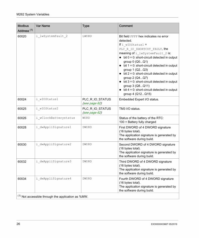
60020 i_lwSystemFault_2 LWORD Bit field FFFF hex indicates no error detected.If i_wIOStatus1 = PLC_R_IO_SHORTCUT_FAULT, the meaning of i_lwSystemFault_2 is: bit 0 = 0: short-circuit detected in output
group 0 (Q0...Q1) bit 1 = 0: short-circuit detected in output
group 1 (Q2...Q3) bit 2 = 0: short-circuit detected in output
group 2 (Q4...Q7) bit 3 = 0: short-circuit detected in output
group 3 (Q8...Q11) bit 4 = 0: short-circuit detected in output
group 4 (Q12...Q15)60024 i_wIOStatus1 PLC_R_IO_STATUS
(see page 62)Embedded Expert I/O status.
60025 i_wIOStatus2 PLC_R_IO_STATUS (see page 62)
TM3 I/O status.
60026 i_wClockBatterystatus WORD Status of the battery of the RTC: 100 = Battery fully charged
60028 i_dwAppliSignature1 DWORD First DWORD of 4 DWORD signature (16 bytes total).The application signature is generated by the software during build.
60030 i_dwAppliSignature2 DWORD Second DWORD of 4 DWORD signature (16 bytes total).The application signature is generated by the software during build.
60032 i_dwAppliSignature3 DWORD Third DWORD of 4 DWORD signature (16 bytes total).The application signature is generated by the software during build.
60034 i_dwAppliSignature4 DWORD Fourth DWORD of 4 DWORD signature (16 bytes total).The application signature is generated by the software during build.
(1) Not accessible through the application as %MW.
Modbus Address (1)
Var Name Type Comment
26 EIO0000003667 05/2019
M262 System Variables
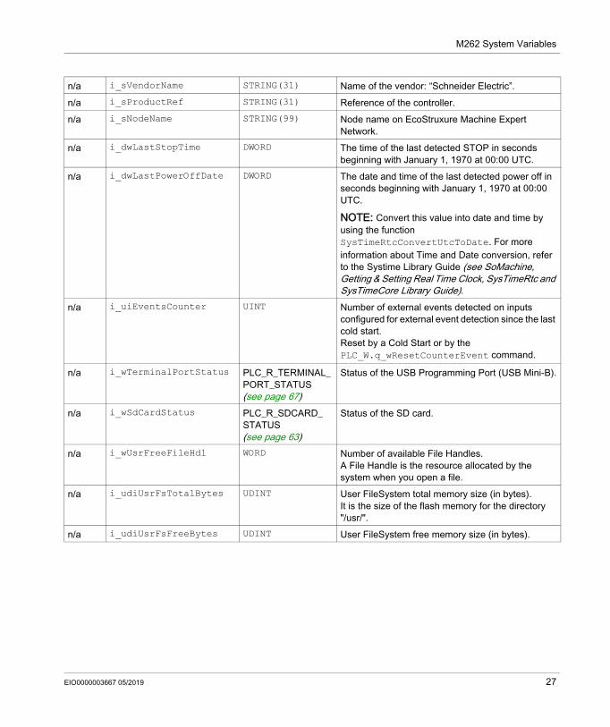
n/a i_sVendorName STRING(31) Name of the vendor: “Schneider Electric”.n/a i_sProductRef STRING(31) Reference of the controller.n/a i_sNodeName STRING(99) Node name on EcoStruxure Machine Expert
Network.n/a i_dwLastStopTime DWORD The time of the last detected STOP in seconds
beginning with January 1, 1970 at 00:00 UTC.n/a i_dwLastPowerOffDate DWORD The date and time of the last detected power off in
seconds beginning with January 1, 1970 at 00:00 UTC.
NOTE: Convert this value into date and time by using the function SysTimeRtcConvertUtcToDate. For more information about Time and Date conversion, refer to the Systime Library Guide (see SoMachine, Getting & Setting Real Time Clock, SysTimeRtc and SysTimeCore Library Guide).
n/a i_uiEventsCounter UINT Number of external events detected on inputs configured for external event detection since the last cold start.Reset by a Cold Start or by the PLC_W.q_wResetCounterEvent command.
n/a i_wTerminalPortStatus PLC_R_TERMINAL_PORT_STATUS (see page 67)
Status of the USB Programming Port (USB Mini-B).
n/a i_wSdCardStatus PLC_R_SDCARD_ STATUS (see page 63)
Status of the SD card.
n/a i_wUsrFreeFileHdl WORD Number of available File Handles.A File Handle is the resource allocated by the system when you open a file.
n/a i_udiUsrFsTotalBytes UDINT User FileSystem total memory size (in bytes).It is the size of the flash memory for the directory "/usr/".
n/a i_udiUsrFsFreeBytes UDINT User FileSystem free memory size (in bytes).
EIO0000003667 05/2019 27
M262 System Variables
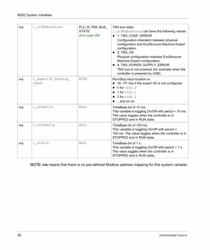
NOTE: n/a means that there is no pre-defined Modbus address mapping for this system variable.
n/a i_uiTM3BusState PLC_R_TM3_BUS_ STATE (see page 68)
TM3 bus state.i_uiTM3BusState can have the following values: 1: TM3_CONF_ERROR
Configuration mismatch between physical configuration and EcoStruxure Machine Expert configuration.
3: TM3_OKPhysical configuration matches EcoStruxure Machine Expert configuration.
4: TM3_POWER_SUPPLY_ERRORTM3 bus is not powered (for example when the controller is powered by USB).
n/a i_ExpertIO_RunStop_ Input
BYTE Run/Stop input location is: 16...FF hex if the expert I/O is not configured 0 for %IX0.0 1 for %IX0.1 2 for %IX0.2 ...and so on.
n/a i_x10msClk BOOL TimeBase bit of 10 ms.This variable is toggling On/Off with period = 10 ms. The value toggles when the controller is in STOPPED and in RUN state.
n/a i_x100msClk BOOL TimeBase bit of 100 ms.This variable is toggling On/Off with period = 100 ms. The value toggles when the controller is in STOPPED and in RUN state.
n/a i_x1sClk BOOL TimeBase bit of 1 s.This variable is toggling On/Off with period = 1 s. The value toggles when the controller is in STOPPED and in RUN state.
28 EIO0000003667 05/2019
M262 System Variables
PLC_W: Controller Read/Write System Variables
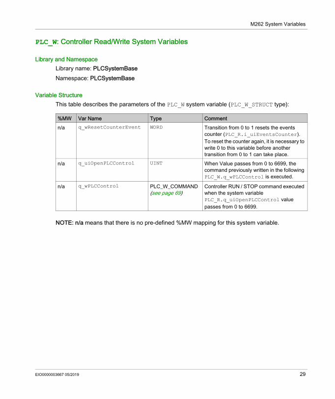
Library and NamespaceLibrary name: PLCSystemBaseNamespace: PLCSystemBase
Variable StructureThis table describes the parameters of the PLC_W system variable (PLC_W_STRUCT type):
NOTE: n/a means that there is no pre-defined %MW mapping for this system variable.
%MW Var Name Type Commentn/a q_wResetCounterEvent WORD Transition from 0 to 1 resets the events
counter (PLC_R.i_uiEventsCounter).To reset the counter again, it is necessary to write 0 to this variable before another transition from 0 to 1 can take place.
n/a q_uiOpenPLCControl UINT When Value passes from 0 to 6699, the command previously written in the following PLC_W.q_wPLCControl is executed.
n/a q_wPLCControl PLC_W_COMMAND (see page 69)
Controller RUN / STOP command executed when the system variable PLC_R.q_uiOpenPLCControl value passes from 0 to 6699.
EIO0000003667 05/2019 29
M262 System Variables
ETH_R and ETH_W Structures
Section 1.3ETH_R and ETH_W Structures
OverviewThis section lists and describes the different system variables included in the ETH_R and ETH_W structures.
What Is in This Section?This section contains the following topics:
Topic PageETH_R: Ethernet Port Read-Only System Variables 31
ETH_W: Ethernet Port Read/Write System Variables 36
30 EIO0000003667 05/2019
M262 System Variables
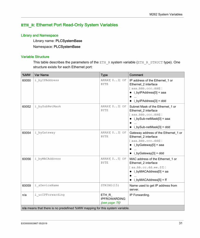
ETH_R: Ethernet Port Read-Only System Variables
Library and NamespaceLibrary name: PLCSystemBaseNamespace: PLCSystemBase
Variable StructureThis table describes the parameters of the ETH_R system variable (ETH_R_STRUCT type). One structure exists for each Ethernet port:
%MW Var Name Type Comment60050 i_byIPAddress ARRAY[0..3] OF
BYTEIP address of the Ethernet_1 or Ethernet_2 interface [aaa.bbb.ccc.ddd]: i_byIPAddress[0] = aaa ... i_byIPAddress[3] = ddd
60052 i_bySubNetMask ARRAY[0..3] OF BYTE
Subnet Mask of the Ethernet_1 or Ethernet_2 interface [aaa.bbb.ccc.ddd]: i_bySub-netMask[0] = aaa ... i_bySub-netMask[3] = ddd
60054 i_byGateway ARRAY[0..3] OF BYTE
Gateway address of the Ethernet_1 or Ethernet_2 interface [aaa.bbb.ccc.ddd]: i_byGateway[0] = aaa ... i_byGateway[3] = ddd
60056 i_byMACAddress ARRAY[0..5] OF BYTE
MAC address of the Ethernet_1 or Ethernet_2 interface [aa.bb.cc.dd.ee.ff]: i_byMACAddress[0] = aa ... i_byMACAddress[5] = ff
60059 i_sDeviceName STRING(15) Name used to get IP address from server.
n/a i_ucIPForwarding ETH_R_ IPFROWARDING (see page 76)
IP Forwarding.
n/a means that there is no predefined %MW mapping for this system variable.
EIO0000003667 05/2019 31
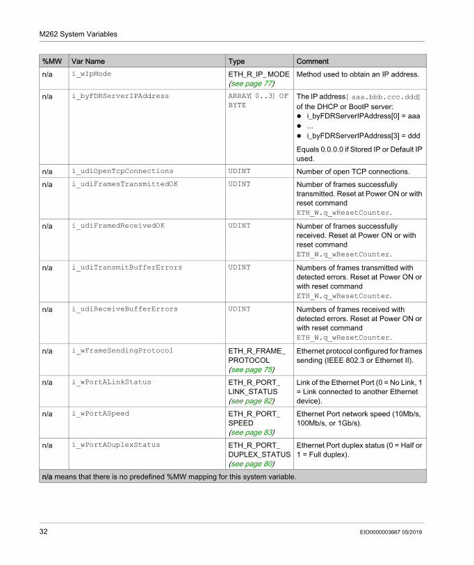
M262 System Variables
n/a i_wIpMode ETH_R_IP_ MODE (see page 77)
Method used to obtain an IP address.
n/a i_byFDRServerIPAddress ARRAY[0..3] OF BYTE
The IP address [aaa.bbb.ccc.ddd] of the DHCP or BootP server: i_byFDRServerIPAddress[0] = aaa ... i_byFDRServerIPAddress[3] = ddd
Equals 0.0.0.0 if Stored IP or Default IP used.
n/a i_udiOpenTcpConnections UDINT Number of open TCP connections.n/a i_udiFramesTransmittedOK UDINT Number of frames successfully
transmitted. Reset at Power ON or with reset command ETH_W.q_wResetCounter.
n/a i_udiFramedReceivedOK UDINT Number of frames successfully received. Reset at Power ON or with reset command ETH_W.q_wResetCounter.
n/a i_udiTransmitBufferErrors UDINT Numbers of frames transmitted with detected errors. Reset at Power ON or with reset command ETH_W.q_wResetCounter.
n/a i_udiReceiveBufferErrors UDINT Numbers of frames received with detected errors. Reset at Power ON or with reset command ETH_W.q_wResetCounter.
n/a i_wFrameSendingProtocol ETH_R_FRAME_ PROTOCOL (see page 75)
Ethernet protocol configured for frames sending (IEEE 802.3 or Ethernet II).
n/a i_wPortALinkStatus ETH_R_PORT_ LINK_STATUS (see page 82)
Link of the Ethernet Port (0 = No Link, 1 = Link connected to another Ethernet device).
n/a i_wPortASpeed ETH_R_PORT_ SPEED (see page 83)
Ethernet Port network speed (10Mb/s, 100Mb/s, or 1Gb/s).
n/a i_wPortADuplexStatus ETH_R_PORT_ DUPLEX_STATUS (see page 80)
Ethernet Port duplex status (0 = Half or 1 = Full duplex).
%MW Var Name Type Comment
n/a means that there is no predefined %MW mapping for this system variable.
32 EIO0000003667 05/2019
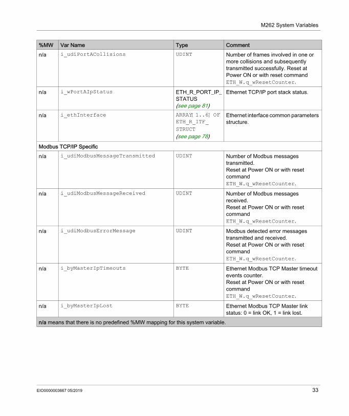
M262 System Variables
n/a i_udiPortACollisions UDINT Number of frames involved in one or more collisions and subsequently transmitted successfully. Reset at Power ON or with reset command ETH_W.q_wResetCounter.
n/a i_wPortAIpStatus ETH_R_PORT_IP_STATUS (see page 81)
Ethernet TCP/IP port stack status.
n/a i_ethInterface ARRAY[1..6] OF ETH_R_ITF_ STRUCT (see page 78)
Ethernet interface common parameters structure.
Modbus TCP/IP Specificn/a i_udiModbusMessageTransmitted UDINT Number of Modbus messages
transmitted.Reset at Power ON or with reset command ETH_W.q_wResetCounter.
n/a i_udiModbusMessageReceived UDINT Number of Modbus messages received.Reset at Power ON or with reset command ETH_W.q_wResetCounter.
n/a i_udiModbusErrorMessage UDINT Modbus detected error messages transmitted and received.Reset at Power ON or with reset command ETH_W.q_wResetCounter.
n/a i_byMasterIpTimeouts BYTE Ethernet Modbus TCP Master timeout events counter.Reset at Power ON or with reset command ETH_W.q_wResetCounter.
n/a i_byMasterIpLost BYTE Ethernet Modbus TCP Master link status: 0 = link OK, 1 = link lost.
%MW Var Name Type Comment
n/a means that there is no predefined %MW mapping for this system variable.
EIO0000003667 05/2019 33
M262 System Variables
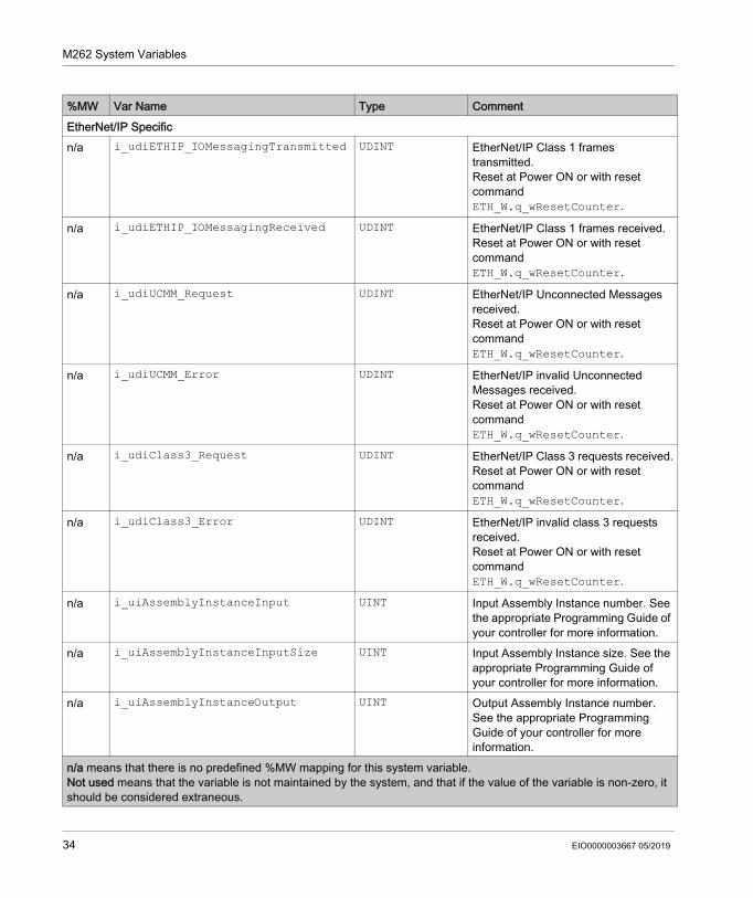
%MW Var Name Type CommentEtherNet/IP Specificn/a i_udiETHIP_IOMessagingTransmitted UDINT EtherNet/IP Class 1 frames
transmitted.Reset at Power ON or with reset command ETH_W.q_wResetCounter.
n/a i_udiETHIP_IOMessagingReceived UDINT EtherNet/IP Class 1 frames received.Reset at Power ON or with reset command ETH_W.q_wResetCounter.
n/a i_udiUCMM_Request UDINT EtherNet/IP Unconnected Messages received.Reset at Power ON or with reset command ETH_W.q_wResetCounter.
n/a i_udiUCMM_Error UDINT EtherNet/IP invalid Unconnected Messages received.Reset at Power ON or with reset command ETH_W.q_wResetCounter.
n/a i_udiClass3_Request UDINT EtherNet/IP Class 3 requests received.Reset at Power ON or with reset command ETH_W.q_wResetCounter.
n/a i_udiClass3_Error UDINT EtherNet/IP invalid class 3 requests received.Reset at Power ON or with reset command ETH_W.q_wResetCounter.
n/a i_uiAssemblyInstanceInput UINT Input Assembly Instance number. See the appropriate Programming Guide of your controller for more information.
n/a i_uiAssemblyInstanceInputSize UINT Input Assembly Instance size. See the appropriate Programming Guide of your controller for more information.
n/a i_uiAssemblyInstanceOutput UINT Output Assembly Instance number. See the appropriate Programming Guide of your controller for more information.
n/a means that there is no predefined %MW mapping for this system variable.Not used means that the variable is not maintained by the system, and that if the value of the variable is non-zero, it should be considered extraneous.
34 EIO0000003667 05/2019
M262 System Variables
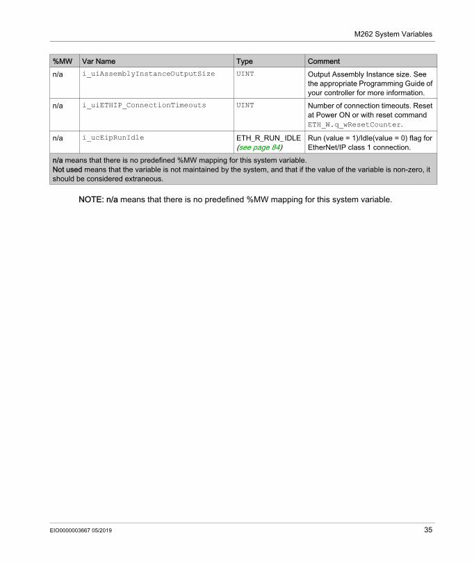
NOTE: n/a means that there is no predefined %MW mapping for this system variable.
n/a i_uiAssemblyInstanceOutputSize UINT Output Assembly Instance size. See the appropriate Programming Guide of your controller for more information.
n/a i_uiETHIP_ConnectionTimeouts UINT Number of connection timeouts. Reset at Power ON or with reset command ETH_W.q_wResetCounter.
n/a i_ucEipRunIdle ETH_R_RUN_ IDLE (see page 84)
Run (value = 1)/Idle(value = 0) flag for EtherNet/IP class 1 connection.
%MW Var Name Type Comment
n/a means that there is no predefined %MW mapping for this system variable.Not used means that the variable is not maintained by the system, and that if the value of the variable is non-zero, it should be considered extraneous.
EIO0000003667 05/2019 35
M262 System Variables
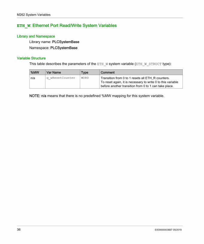
ETH_W: Ethernet Port Read/Write System Variables
Library and NamespaceLibrary name: PLCSystemBaseNamespace: PLCSystemBase
Variable StructureThis table describes the parameters of the ETH_W system variable (ETH_W_STRUCT type):
NOTE: n/a means that there is no predefined %MW mapping for this system variable.
%MW Var Name Type Commentn/a q_wResetCounter WORD Transition from 0 to 1 resets all ETH_R counters.
To reset again, it is necessary to write 0 to this variable before another transition from 0 to 1 can take place.
36 EIO0000003667 05/2019
Modicon M262 Logic/Motion ControllerM262, System FunctionsEIO0000003667 05/2019
M262 System Functions
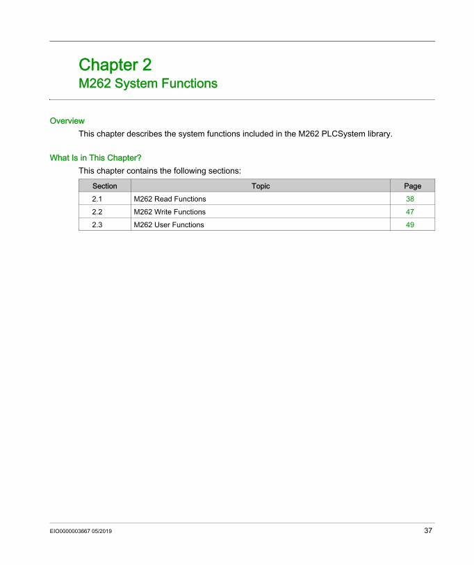
Chapter 2M262 System Functions
OverviewThis chapter describes the system functions included in the M262 PLCSystem library.
What Is in This Chapter?This chapter contains the following sections:
Section Topic Page2.1 M262 Read Functions 382.2 M262 Write Functions 472.3 M262 User Functions 49
EIO0000003667 05/2019 37
M262, System Functions
M262 Read Functions
Section 2.1M262 Read Functions
OverviewThis section describes the read functions included in the M262 PLCSystem library.
What Is in This Section?This section contains the following topics:
Topic PageGetImmediateFastInput: Read Input of an Embedded Expert I/O 39
GetRtc: Get Real Time Clock 41
IsFirstMastColdCycle: Indicate if this Cycle is the First MAST Cold Start Cycle 42
IsFirstMastCycle: Indicate if this Cycle is the First MAST Cycle 43
IsFirstMastWarmCycle: Indicate if this Cycle is the First MAST Warm Start Cycle 45
GetExternalEventValue: Get Current Value of an External Event 46
38 EIO0000003667 05/2019
M262, System Functions
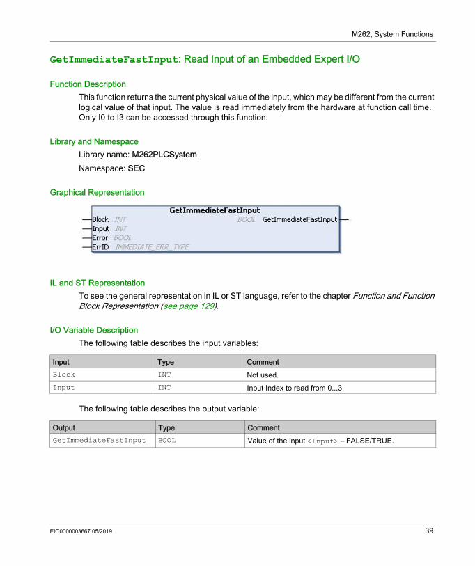
GetImmediateFastInput: Read Input of an Embedded Expert I/O
Function DescriptionThis function returns the current physical value of the input, which may be different from the current logical value of that input. The value is read immediately from the hardware at function call time. Only I0 to I3 can be accessed through this function.
Library and NamespaceLibrary name: M262PLCSystemNamespace: SEC
Graphical Representation
IL and ST RepresentationTo see the general representation in IL or ST language, refer to the chapter Function and Function Block Representation (see page 129).
I/O Variable DescriptionThe following table describes the input variables:
The following table describes the output variable:
Input Type CommentBlock INT Not used.Input INT Input Index to read from 0...3.
Output Type CommentGetImmediateFastInput BOOL Value of the input <Input> – FALSE/TRUE.
EIO0000003667 05/2019 39
M262, System Functions
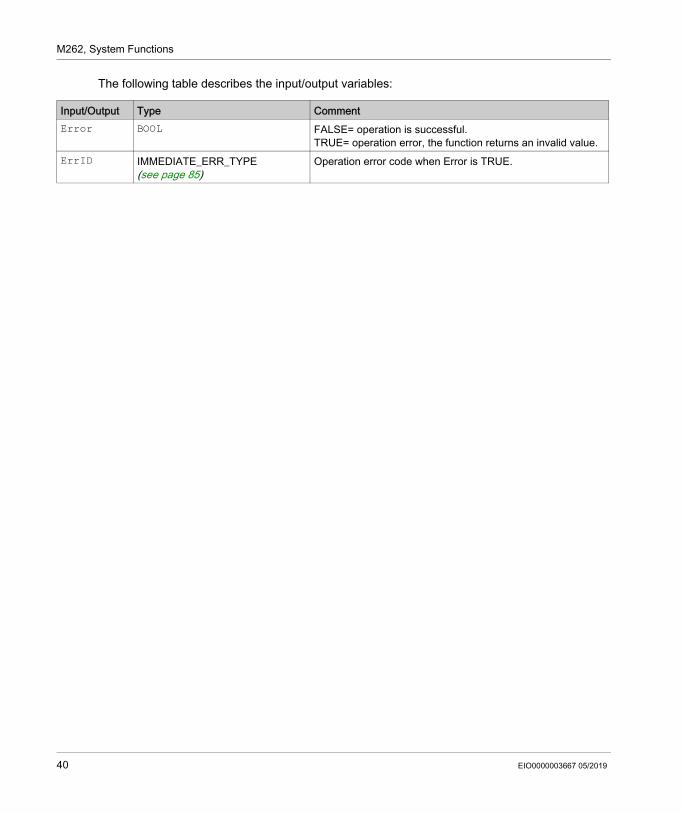
The following table describes the input/output variables:
Input/Output Type CommentError BOOL FALSE= operation is successful.
TRUE= operation error, the function returns an invalid value.ErrID IMMEDIATE_ERR_TYPE
(see page 85)Operation error code when Error is TRUE.
40 EIO0000003667 05/2019
M262, System Functions
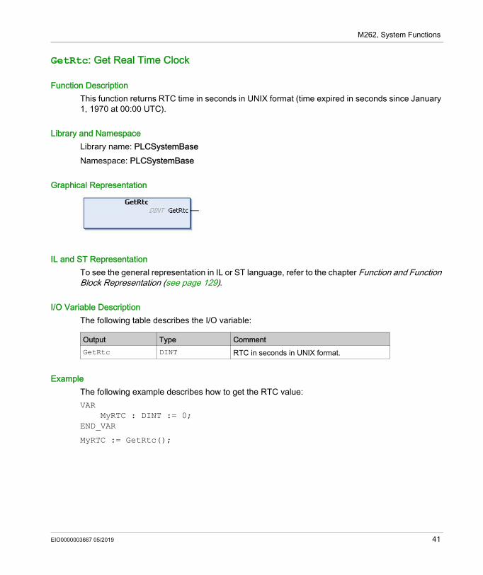
GetRtc: Get Real Time Clock
Function DescriptionThis function returns RTC time in seconds in UNIX format (time expired in seconds since January 1, 1970 at 00:00 UTC).
Library and NamespaceLibrary name: PLCSystemBaseNamespace: PLCSystemBase
Graphical Representation
IL and ST RepresentationTo see the general representation in IL or ST language, refer to the chapter Function and Function Block Representation (see page 129).
I/O Variable DescriptionThe following table describes the I/O variable:
ExampleThe following example describes how to get the RTC value:VAR MyRTC : DINT := 0;END_VAR
MyRTC := GetRtc();
Output Type CommentGetRtc DINT RTC in seconds in UNIX format.
EIO0000003667 05/2019 41
M262, System Functions
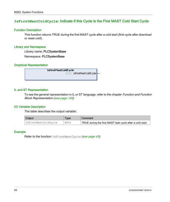
IsFirstMastColdCycle: Indicate if this Cycle is the First MAST Cold Start Cycle
Function DescriptionThis function returns TRUE during the first MAST cycle after a cold start (first cycle after download or reset cold).
Library and NamespaceLibrary name: PLCSystemBaseNamespace: PLCSystemBase
Graphical Representation
IL and ST RepresentationTo see the general representation in IL or ST language, refer to the chapter Function and Function Block Representation (see page 129).
I/O Variable DescriptionThe table describes the output variable:
ExampleRefer to the function IsFirstMastCycle (see page 43).
Output Type CommentIsFirstMastColdCycle BOOL TRUE during the first MAST task cycle after a cold start.
42 EIO0000003667 05/2019
M262, System Functions
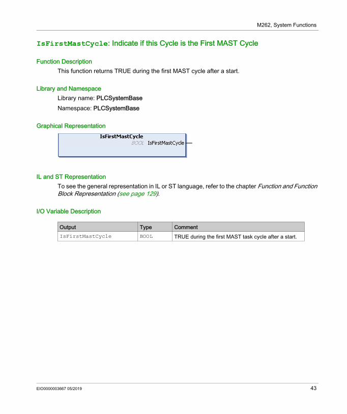
IsFirstMastCycle: Indicate if this Cycle is the First MAST Cycle
Function DescriptionThis function returns TRUE during the first MAST cycle after a start.
Library and NamespaceLibrary name: PLCSystemBaseNamespace: PLCSystemBase
Graphical Representation
IL and ST RepresentationTo see the general representation in IL or ST language, refer to the chapter Function and Function Block Representation (see page 129).
I/O Variable Description
Output Type CommentIsFirstMastCycle BOOL TRUE during the first MAST task cycle after a start.
EIO0000003667 05/2019 43
M262, System Functions
ExampleThis example describes the three functions IsFirstMastCycle, IsFirstMastColdCycle and IsFirstMastWarmCycle used together.
Use this example in MAST task. Otherwise, it may run several times or possibly never (an additional task might be called several times or not called during 1 MAST task cycle):VARMyIsFirstMastCycle : BOOL;MyIsFirstMastWarmCycle : BOOL;MyIsFirstMastColdCycle : BOOL;END_VAR
MyIsFirstMastWarmCycle := IsFirstMastWarmCycle();MyIsFirstMastColdCycle := IsFirstMastColdCycle();MyIsFirstMastCycle := IsFirstMastCycle();
IF (MyIsFirstMastWarmCycle) THEN
(*This is the first Mast Cycle after a Warm Start: all variables are set to their initialization values except the Retain variables*)
(*=> initialize the needed variables so that your application runs as expected in this case*)
END_IF;
IF (MyIsFirstMastColdCycle) THEN
(*This is the first Mast Cycle after a Cold Start: all variables are set to their initialization values including the Retain Variables*)
(*=> initialize the needed variables so that your application runs as expected in this case*)
END_IF;
IF (MyIsFirstMastCycle) THEN
(*This is the first Mast Cycle after a Start, i.e. after a Warm or Cold Start as well as STOP/RUN commands*)
(*=> initialize the needed variables so that your application runs as expected in this case*)
END_IF;
44 EIO0000003667 05/2019
M262, System Functions
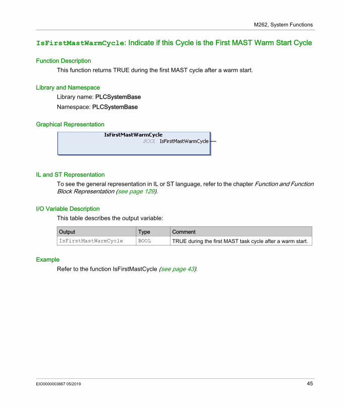
IsFirstMastWarmCycle: Indicate if this Cycle is the First MAST Warm Start Cycle
Function DescriptionThis function returns TRUE during the first MAST cycle after a warm start.
Library and NamespaceLibrary name: PLCSystemBaseNamespace: PLCSystemBase
Graphical Representation
IL and ST RepresentationTo see the general representation in IL or ST language, refer to the chapter Function and Function Block Representation (see page 129).
I/O Variable DescriptionThis table describes the output variable:
ExampleRefer to the function IsFirstMastCycle (see page 43).
Output Type CommentIsFirstMastWarmCycle BOOL TRUE during the first MAST task cycle after a warm start.
EIO0000003667 05/2019 45
M262, System Functions
GetExternalEventValue: Get Current Value of an External Event
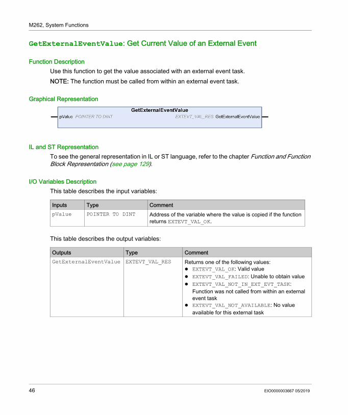
Function DescriptionUse this function to get the value associated with an external event task.NOTE: The function must be called from within an external event task.
Graphical Representation
IL and ST RepresentationTo see the general representation in IL or ST language, refer to the chapter Function and Function Block Representation (see page 129).
I/O Variables DescriptionThis table describes the input variables:
This table describes the output variables:
Inputs Type CommentpValue POINTER TO DINT Address of the variable where the value is copied if the function
returns EXTEVT_VAL_OK.
Outputs Type CommentGetExternalEventValue EXTEVT_VAL_RES Returns one of the following values:
EXTEVT_VAL_OK: Valid value EXTEVT_VAL_FAILED: Unable to obtain value EXTEVT_VAL_NOT_IN_EXT_EVT_TASK:
Function was not called from within an external event task
EXTEVT_VAL_NOT_AVAILABLE: No value available for this external task
46 EIO0000003667 05/2019
M262, System Functions
M262 Write Functions
Section 2.2M262 Write Functions
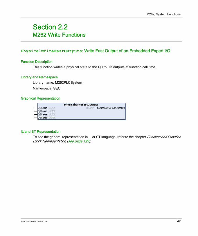
PhysicalWriteFastOutputs: Write Fast Output of an Embedded Expert I/O
Function DescriptionThis function writes a physical state to the Q0 to Q3 outputs at function call time.
Library and NamespaceLibrary name: M262PLCSystemNamespace: SEC
Graphical Representation
IL and ST RepresentationTo see the general representation in IL or ST language, refer to the chapter Function and Function Block Representation (see page 129).
EIO0000003667 05/2019 47
M262, System Functions
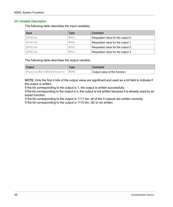
I/O Variable DescriptionThe following table describes the input variables:
The following table describes the output variable:
NOTE: Only the first 4 bits of the output value are significant and used as a bit field to indicate if the output is written.If the bit corresponding to the output is 1, the output is written successfully. If the bit corresponding to the output is 0, the output is not written because it is already used by an expert function.If the bit corresponding to the output is 1111 bin, all of the 4 outputs are written correctly.If the bit corresponding to the output is 1110 bin, Q0 is not written.
Input Type CommentQ0Value BOOL Requested value for the output 0.Q1Value BOOL Requested value for the output 1.Q2Value BOOL Requested value for the output 2.Q3Value BOOL Requested value for the output 3.
Output Type CommentPhysicalWriteFastOutputs WORD Output value of the function.
48 EIO0000003667 05/2019
M262, System Functions
M262 User Functions
Section 2.3M262 User Functions
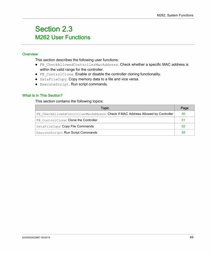
OverviewThis section describes the following user functions: FB_CheckAllowedControllerMacAddress. Check whether a specific MAC address is
within the valid range for the controller. FB_ControlClone. Enable or disable the controller cloning functionality. DataFileCopy. Copy memory data to a file and vice versa. ExecuteScript. Run script commands.
What Is in This Section?This section contains the following topics:
Topic PageFB_CheckAllowedControllerMacAddress: Check If MAC Address Allowed by Controller 50
FB_ControlClone: Clone the Controller 51
DataFileCopy: Copy File Commands 52
ExecuteScript: Run Script Commands 55
EIO0000003667 05/2019 49
M262, System Functions
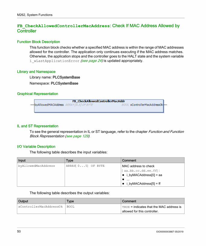
FB_CheckAllowedControllerMacAddress: Check If MAC Address Allowed by Controller
Function Block DescriptionThis function block checks whether a specified MAC address is within the range of MAC addresses allowed for the controller. The application only continues executing if the MAC address matches. Otherwise, the application stops and the controller goes to the HALT state and the system variable i_wLastApplicationError (see page 24) is updated appropriately.
Library and NamespaceLibrary name: PLCSystemBaseNamespace: PLCSystemBase
Graphical Representation
IL and ST RepresentationTo see the general representation in IL or ST language, refer to the chapter Function and Function Block Representation (see page 129).
I/O Variable DescriptionThe following table describes the input variables:
The following table describes the output variables:
Input Type CommentbyAllowedMacAddress ARRAY[0...5] OF BYTE MAC address to check
[aa.bb.cc.dd.ee.ff]: i_byMACAddress[0] = aa ... i_byMACAddress[5] = ff
Output Type CommentxControllerMacAddressOk BOOL TRUE = indicates that the MAC address is
allowed for this controller.
50 EIO0000003667 05/2019
M262, System Functions
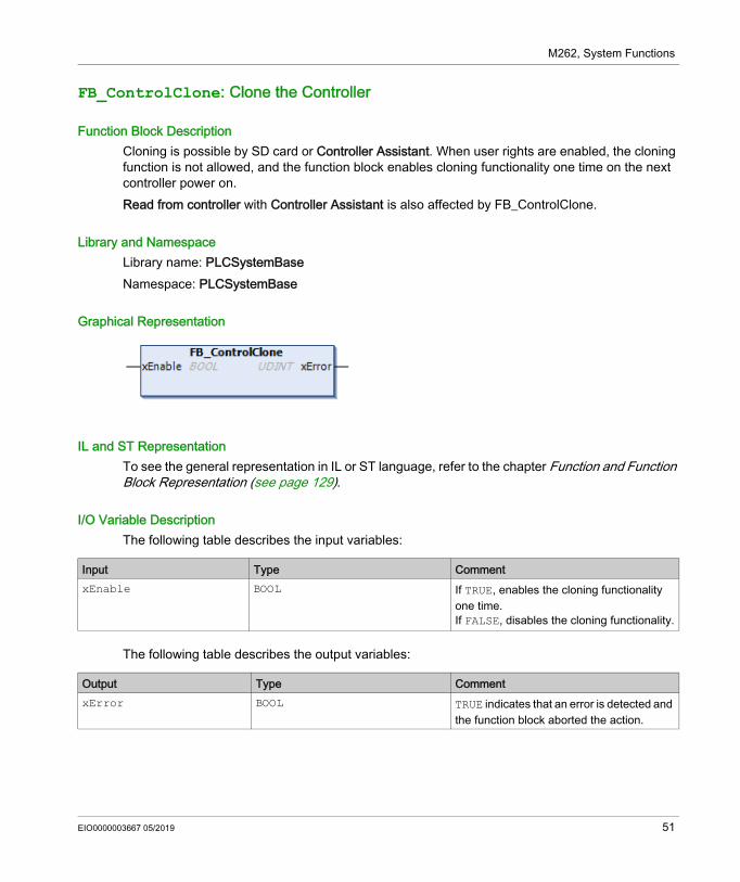
FB_ControlClone: Clone the Controller
Function Block DescriptionCloning is possible by SD card or Controller Assistant. When user rights are enabled, the cloning function is not allowed, and the function block enables cloning functionality one time on the next controller power on.Read from controller with Controller Assistant is also affected by FB_ControlClone.
Library and NamespaceLibrary name: PLCSystemBaseNamespace: PLCSystemBase
Graphical Representation
IL and ST RepresentationTo see the general representation in IL or ST language, refer to the chapter Function and Function Block Representation (see page 129).
I/O Variable DescriptionThe following table describes the input variables:
The following table describes the output variables:
Input Type CommentxEnable BOOL If TRUE, enables the cloning functionality
one time.If FALSE, disables the cloning functionality.
Output Type CommentxError BOOL TRUE indicates that an error is detected and
the function block aborted the action.
EIO0000003667 05/2019 51
M262, System Functions
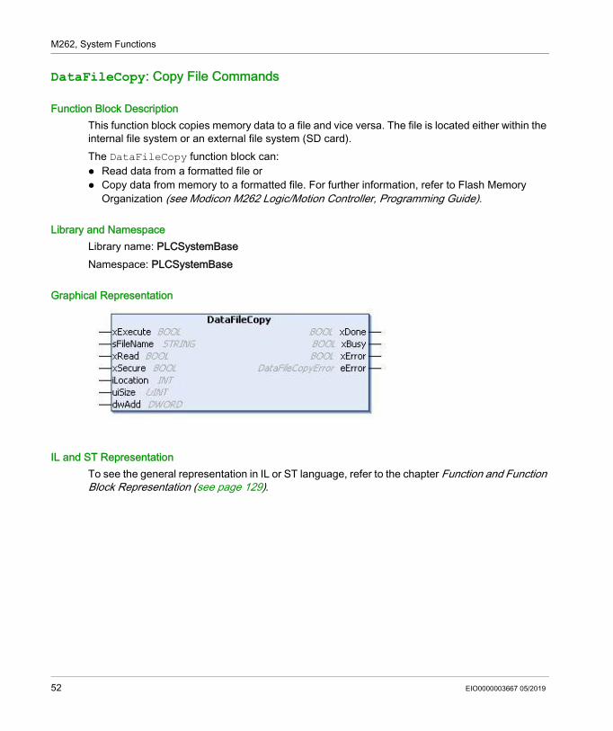
DataFileCopy: Copy File Commands
Function Block DescriptionThis function block copies memory data to a file and vice versa. The file is located either within the internal file system or an external file system (SD card).The DataFileCopy function block can: Read data from a formatted file or Copy data from memory to a formatted file. For further information, refer to Flash Memory
Organization (see Modicon M262 Logic/Motion Controller, Programming Guide).
Library and NamespaceLibrary name: PLCSystemBaseNamespace: PLCSystemBase
Graphical Representation
IL and ST RepresentationTo see the general representation in IL or ST language, refer to the chapter Function and Function Block Representation (see page 129).
52 EIO0000003667 05/2019
M262, System Functions
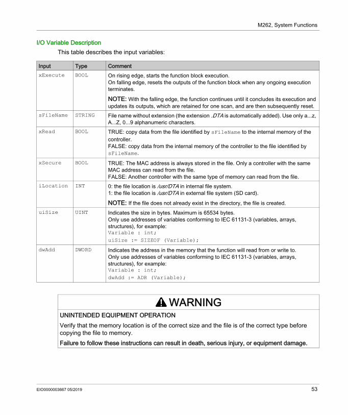
I/O Variable DescriptionThis table describes the input variables:
Input Type CommentxExecute BOOL On rising edge, starts the function block execution.
On falling edge, resets the outputs of the function block when any ongoing execution terminates.
NOTE: With the falling edge, the function continues until it concludes its execution and updates its outputs, which are retained for one scan, and are then subsequently reset.
sFileName STRING File name without extension (the extension .DTA is automatically added). Use only a...z, A...Z, 0...9 alphanumeric characters.
xRead BOOL TRUE: copy data from the file identified by sFileName to the internal memory of the controller.FALSE: copy data from the internal memory of the controller to the file identified by sFileName.
xSecure BOOL TRUE: The MAC address is always stored in the file. Only a controller with the same MAC address can read from the file.FALSE: Another controller with the same type of memory can read from the file.
iLocation INT 0: the file location is /usr/DTA in internal file system.1: the file location is /usr/DTA in external file system (SD card).
NOTE: If the file does not already exist in the directory, the file is created.uiSize UINT Indicates the size in bytes. Maximum is 65534 bytes.
Only use addresses of variables conforming to IEC 61131-3 (variables, arrays, structures), for example: Variable : int;uiSize := SIZEOF (Variable);
dwAdd DWORD Indicates the address in the memory that the function will read from or write to.Only use addresses of variables conforming to IEC 61131-3 (variables, arrays, structures), for example: Variable : int;dwAdd := ADR (Variable);
WARNINGUNINTENDED EQUIPMENT OPERATIONVerify that the memory location is of the correct size and the file is of the correct type before copying the file to memory.Failure to follow these instructions can result in death, serious injury, or equipment damage.
EIO0000003667 05/2019 53
M262, System Functions
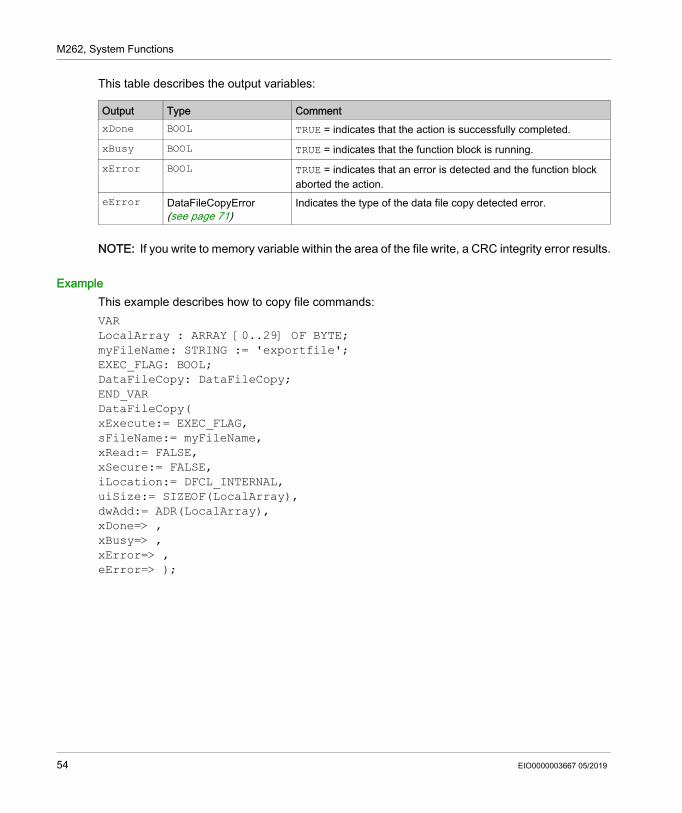
This table describes the output variables:
NOTE: If you write to memory variable within the area of the file write, a CRC integrity error results.
ExampleThis example describes how to copy file commands:VARLocalArray : ARRAY [0..29] OF BYTE;myFileName: STRING := 'exportfile';EXEC_FLAG: BOOL;DataFileCopy: DataFileCopy;END_VARDataFileCopy(xExecute:= EXEC_FLAG,sFileName:= myFileName,xRead:= FALSE,xSecure:= FALSE,iLocation:= DFCL_INTERNAL,uiSize:= SIZEOF(LocalArray),dwAdd:= ADR(LocalArray),xDone=> ,xBusy=> ,xError=> ,eError=> );
Output Type CommentxDone BOOL TRUE = indicates that the action is successfully completed.xBusy BOOL TRUE = indicates that the function block is running.xError BOOL TRUE = indicates that an error is detected and the function block
aborted the action.eError DataFileCopyError
(see page 71)Indicates the type of the data file copy detected error.
54 EIO0000003667 05/2019
M262, System Functions
ExecuteScript: Run Script Commands
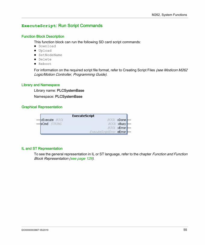
Function Block DescriptionThis function block can run the following SD card script commands: Download Upload SetNodeName Delete Reboot
For information on the required script file format, refer to Creating Script Files (see Modicon M262 Logic/Motion Controller, Programming Guide).
Library and NamespaceLibrary name: PLCSystemBaseNamespace: PLCSystemBase
Graphical Representation
IL and ST RepresentationTo see the general representation in IL or ST language, refer to the chapter Function and Function Block Representation (see page 129).
EIO0000003667 05/2019 55
M262, System Functions
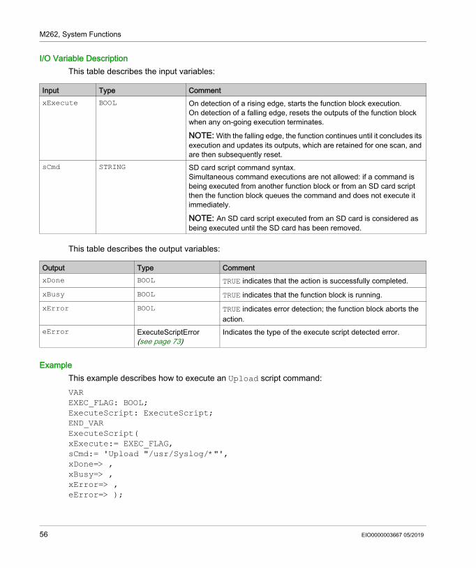
I/O Variable DescriptionThis table describes the input variables:
This table describes the output variables:
ExampleThis example describes how to execute an Upload script command:VAREXEC_FLAG: BOOL;ExecuteScript: ExecuteScript;END_VARExecuteScript(xExecute:= EXEC_FLAG,sCmd:= 'Upload "/usr/Syslog/*"',xDone=> ,xBusy=> ,xError=> ,eError=> );
Input Type CommentxExecute BOOL On detection of a rising edge, starts the function block execution.
On detection of a falling edge, resets the outputs of the function block when any on-going execution terminates.
NOTE: With the falling edge, the function continues until it concludes its execution and updates its outputs, which are retained for one scan, and are then subsequently reset.
sCmd STRING SD card script command syntax.Simultaneous command executions are not allowed: if a command is being executed from another function block or from an SD card script then the function block queues the command and does not execute it immediately.
NOTE: An SD card script executed from an SD card is considered as being executed until the SD card has been removed.
Output Type CommentxDone BOOL TRUE indicates that the action is successfully completed.xBusy BOOL TRUE indicates that the function block is running.xError BOOL TRUE indicates error detection; the function block aborts the
action.eError ExecuteScriptError
(see page 73)Indicates the type of the execute script detected error.
56 EIO0000003667 05/2019
Modicon M262 Logic/Motion ControllerM262 Library Data TypesEIO0000003667 05/2019
M262 Library Data Types
Chapter 3M262 Library Data Types
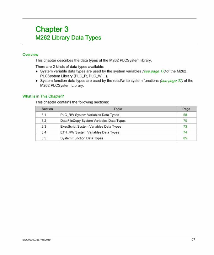
OverviewThis chapter describes the data types of the M262 PLCSystem library.There are 2 kinds of data types available: System variable data types are used by the system variables (see page 17) of the M262
PLCSystem Library (PLC_R, PLC_W,...). System function data types are used by the read/write system functions (see page 37) of the
M262 PLCSystem Library.
What Is in This Chapter?This chapter contains the following sections:
Section Topic Page3.1 PLC_RW System Variables Data Types 583.2 DataFileCopy System Variables Data Types 703.3 ExecScript System Variables Data Types 733.4 ETH_RW System Variables Data Types 743.5 System Function Data Types 85
EIO0000003667 05/2019 57
M262 Library Data Types
PLC_RW System Variables Data Types
Section 3.1PLC_RW System Variables Data Types
OverviewThis section lists and describes the system variable data types included in the PLC_R and PLC_W structures.
What Is in This Section?This section contains the following topics:
Topic PagePLC_R_APPLICATION_ERROR: Detected Application Error Status Codes 59PLC_R_BOOT_PROJECT_STATUS: Boot Project Status Codes 61PLC_R_IO_STATUS: I/O Status Codes 62PLC_R_SDCARD_STATUS: SD Card Slot Status Codes 63PLC_R_STATUS: Controller Status Codes 64PLC_R_STOP_CAUSE: From RUN State to Other State Transition Cause Codes 65PLC_R_TERMINAL_PORT_STATUS: Programming Port Connection Status Codes 67PLC_R_TM3_BUS_STATE: TM3 Bus Status Codes 68PLC_W_COMMAND: Control Command Codes 69
58 EIO0000003667 05/2019
M262 Library Data Types
PLC_R_APPLICATION_ERROR: Detected Application Error Status Codes
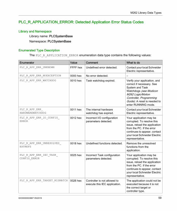
Library and NamespaceLibrary name: PLCSystemBaseNamespace: PLCSystemBase
Enumerated Type DescriptionThe PLC_R_APPLICATION_ERROR enumeration data type contains the following values:
Enumerator Value Comment What to doPLC_R_APP_ERR_UNKNOWN FFFF hex Undefined error detected. Contact your local Schneider
Electric representative.PLC_R_APP_ERR_NOEXCEPTION 0000 hex No error detected. –PLC_R_APP_ERR_WATCHDOG 0010 hex Task watchdog expired. Verify your application, and
correct if necessary. See System and Task Watchdogs (see Modicon M262 Logic/Motion Controller, Programming Guide). A reset is needed to enter RUNNING mode.
PLC_R_APP_ERR_ HARDWAREWATCHDOG
0011 hex The internal hardware watchdog has expired.
Contact your local Schneider Electric representative.
PLC_R_APP_ERR_IO_CONFIG_ ERROR
0012 hex Incorrect I/O configuration parameters detected.
Your application may be corrupted. To resolve this issue, reload the application from the PC. If the error continues to appear, contact your local Schneider Electric representative.
PLC_R_APP_ERR_UNRESOLVED_ EXTREFS
0018 hex Undefined functions detected. Remove the unresolved functions from the application.
PLC_R_APP_ERR_IEC_TASK_ CONFIG_ERROR
0025 hex Incorrect Task configuration parameters detected.
Your application may be corrupted. To resolve this issue, reload the application from the PC. If the error continues to appear, contact your local Schneider Electric representative.
PLC_R_APP_ERR_TARGET_MISMATCH 0026 hex Controller is not allowed to execute this IEC application.
The application could not be executed because it is not the correct target or controller type.
EIO0000003667 05/2019 59
M262 Library Data Types
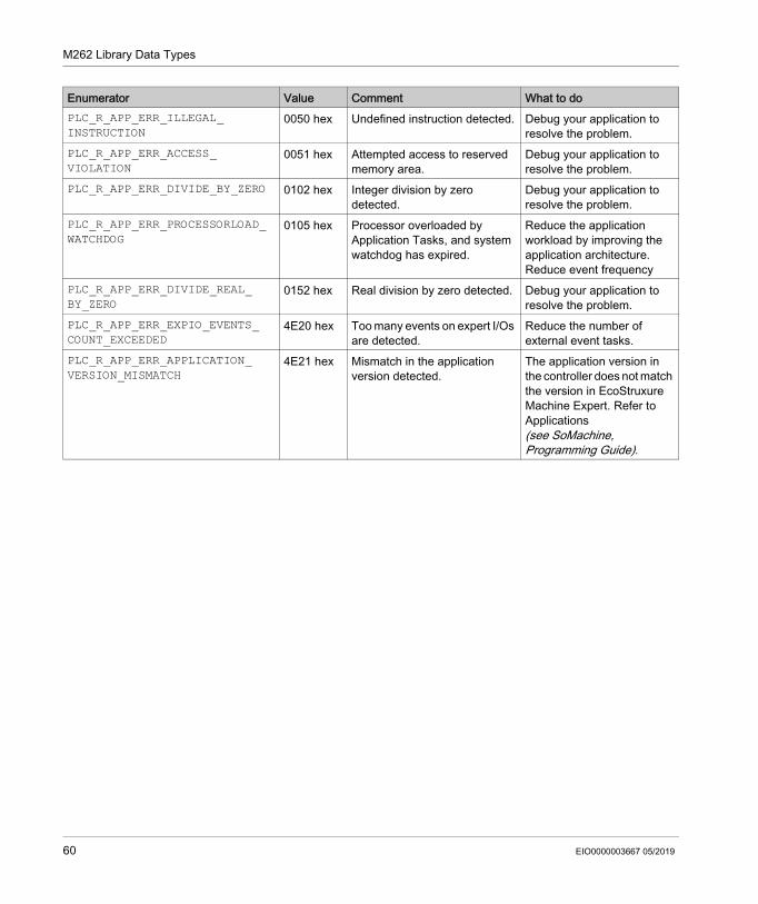
PLC_R_APP_ERR_ILLEGAL_ INSTRUCTION
0050 hex Undefined instruction detected. Debug your application to resolve the problem.
PLC_R_APP_ERR_ACCESS_ VIOLATION
0051 hex Attempted access to reserved memory area.
Debug your application to resolve the problem.
PLC_R_APP_ERR_DIVIDE_BY_ZERO 0102 hex Integer division by zero detected.
Debug your application to resolve the problem.
PLC_R_APP_ERR_PROCESSORLOAD_ WATCHDOG
0105 hex Processor overloaded by Application Tasks, and system watchdog has expired.
Reduce the application workload by improving the application architecture.Reduce event frequency
PLC_R_APP_ERR_DIVIDE_REAL_ BY_ZERO
0152 hex Real division by zero detected. Debug your application to resolve the problem.
PLC_R_APP_ERR_EXPIO_EVENTS_ COUNT_EXCEEDED
4E20 hex Too many events on expert I/Os are detected.
Reduce the number of external event tasks.
PLC_R_APP_ERR_APPLICATION_ VERSION_MISMATCH
4E21 hex Mismatch in the application version detected.
The application version in the controller does not match the version in EcoStruxure Machine Expert. Refer to Applications (see SoMachine, Programming Guide).
Enumerator Value Comment What to do
60 EIO0000003667 05/2019
M262 Library Data Types
PLC_R_BOOT_PROJECT_STATUS: Boot Project Status Codes
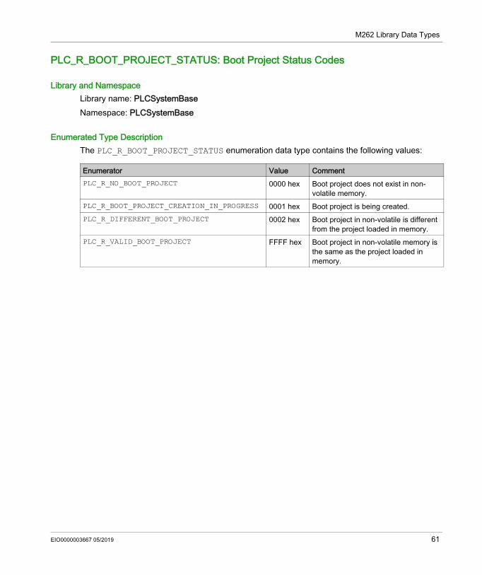
Library and NamespaceLibrary name: PLCSystemBaseNamespace: PLCSystemBase
Enumerated Type Description The PLC_R_BOOT_PROJECT_STATUS enumeration data type contains the following values:
Enumerator Value CommentPLC_R_NO_BOOT_PROJECT 0000 hex Boot project does not exist in non-
volatile memory.PLC_R_BOOT_PROJECT_CREATION_IN_PROGRESS 0001 hex Boot project is being created.PLC_R_DIFFERENT_BOOT_PROJECT 0002 hex Boot project in non-volatile is different
from the project loaded in memory.PLC_R_VALID_BOOT_PROJECT FFFF hex Boot project in non-volatile memory is
the same as the project loaded in memory.
EIO0000003667 05/2019 61
M262 Library Data Types
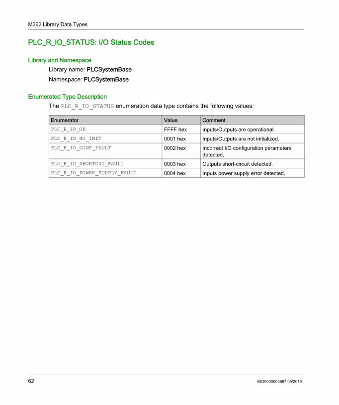
PLC_R_IO_STATUS: I/O Status Codes
Library and NamespaceLibrary name: PLCSystemBaseNamespace: PLCSystemBase
Enumerated Type Description The PLC_R_IO_STATUS enumeration data type contains the following values:
Enumerator Value CommentPLC_R_IO_OK FFFF hex Inputs/Outputs are operational.PLC_R_IO_NO_INIT 0001 hex Inputs/Outputs are not initialized.PLC_R_IO_CONF_FAULT 0002 hex Incorrect I/O configuration parameters
detected.PLC_R_IO_SHORTCUT_FAULT 0003 hex Outputs short-circuit detected.PLC_R_IO_POWER_SUPPLY_FAULT 0004 hex Inputs power supply error detected.
62 EIO0000003667 05/2019
M262 Library Data Types
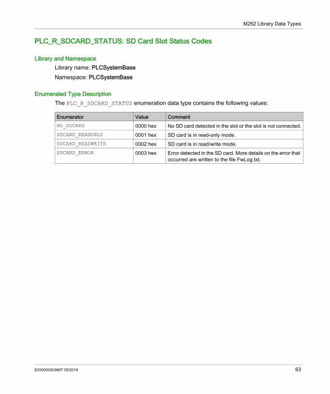
PLC_R_SDCARD_STATUS: SD Card Slot Status Codes
Library and NamespaceLibrary name: PLCSystemBaseNamespace: PLCSystemBase
Enumerated Type DescriptionThe PLC_R_SDCARD_STATUS enumeration data type contains the following values:
Enumerator Value CommentNO_SDCARD 0000 hex No SD card detected in the slot or the slot is not connected.SDCARD_READONLY 0001 hex SD card is in read-only mode.SDCARD_READWRITE 0002 hex SD card is in read/write mode.SDCARD_ERROR 0003 hex Error detected in the SD card. More details on the error that
occurred are written to the file FwLog.txt.
EIO0000003667 05/2019 63
M262 Library Data Types
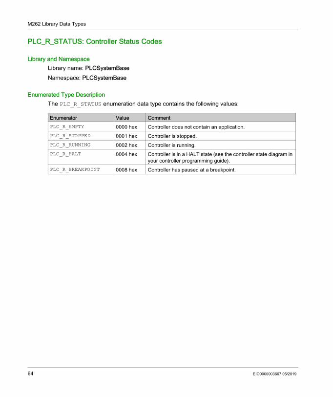
PLC_R_STATUS: Controller Status Codes
Library and NamespaceLibrary name: PLCSystemBaseNamespace: PLCSystemBase
Enumerated Type Description The PLC_R_STATUS enumeration data type contains the following values:
Enumerator Value CommentPLC_R_EMPTY 0000 hex Controller does not contain an application.PLC_R_STOPPED 0001 hex Controller is stopped.PLC_R_RUNNING 0002 hex Controller is running.PLC_R_HALT 0004 hex Controller is in a HALT state (see the controller state diagram in
your controller programming guide).PLC_R_BREAKPOINT 0008 hex Controller has paused at a breakpoint.
64 EIO0000003667 05/2019
M262 Library Data Types
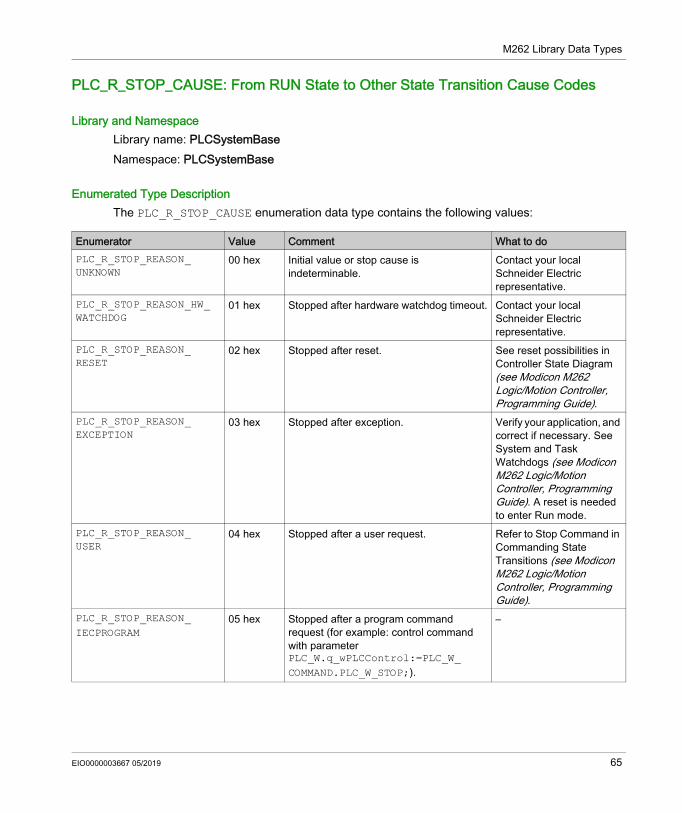
PLC_R_STOP_CAUSE: From RUN State to Other State Transition Cause Codes
Library and NamespaceLibrary name: PLCSystemBaseNamespace: PLCSystemBase
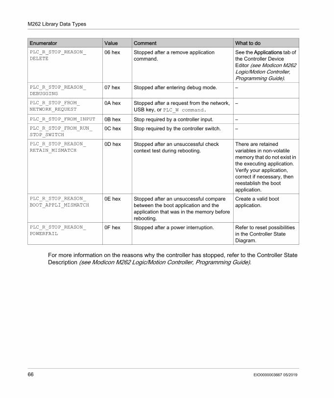
Enumerated Type DescriptionThe PLC_R_STOP_CAUSE enumeration data type contains the following values:
Enumerator Value Comment What to doPLC_R_STOP_REASON_ UNKNOWN
00 hex Initial value or stop cause is indeterminable.
Contact your local Schneider Electric representative.
PLC_R_STOP_REASON_HW_ WATCHDOG
01 hex Stopped after hardware watchdog timeout. Contact your local Schneider Electric representative.
PLC_R_STOP_REASON_ RESET
02 hex Stopped after reset. See reset possibilities in Controller State Diagram (see Modicon M262 Logic/Motion Controller, Programming Guide).
PLC_R_STOP_REASON_ EXCEPTION
03 hex Stopped after exception. Verify your application, and correct if necessary. See System and Task Watchdogs (see Modicon M262 Logic/Motion Controller, Programming Guide). A reset is needed to enter Run mode.
PLC_R_STOP_REASON_ USER
04 hex Stopped after a user request. Refer to Stop Command in Commanding State Transitions (see Modicon M262 Logic/Motion Controller, Programming Guide).
PLC_R_STOP_REASON_ IECPROGRAM
05 hex Stopped after a program command request (for example: control command with parameter PLC_W.q_wPLCControl:=PLC_W_ COMMAND.PLC_W_STOP;).
–
EIO0000003667 05/2019 65
M262 Library Data Types
For more information on the reasons why the controller has stopped, refer to the Controller State Description (see Modicon M262 Logic/Motion Controller, Programming Guide).
PLC_R_STOP_REASON_ DELETE
06 hex Stopped after a remove application command.
See the Applications tab of the Controller Device Editor (see Modicon M262 Logic/Motion Controller, Programming Guide).
PLC_R_STOP_REASON_ DEBUGGING
07 hex Stopped after entering debug mode. –
PLC_R_STOP_FROM_ NETWORK_REQUEST
0A hex Stopped after a request from the network, USB key, or PLC_W command.
–
PLC_R_STOP_FROM_INPUT 0B hex Stop required by a controller input. –PLC_R_STOP_FROM_RUN_ STOP_SWITCH
0C hex Stop required by the controller switch. –
PLC_R_STOP_REASON_ RETAIN_MISMATCH
0D hex Stopped after an unsuccessful check context test during rebooting.
There are retained variables in non-volatile memory that do not exist in the executing application.Verify your application, correct if necessary, then reestablish the boot application.
PLC_R_STOP_REASON_ BOOT_APPLI_MISMATCH
0E hex Stopped after an unsuccessful compare between the boot application and the application that was in the memory before rebooting.
Create a valid boot application.
PLC_R_STOP_REASON_ POWERFAIL
0F hex Stopped after a power interruption. Refer to reset possibilities in the Controller State Diagram.
Enumerator Value Comment What to do
66 EIO0000003667 05/2019
M262 Library Data Types
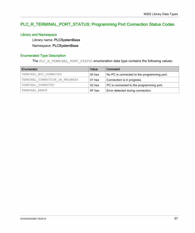
PLC_R_TERMINAL_PORT_STATUS: Programming Port Connection Status Codes
Library and NamespaceLibrary name: PLCSystemBaseNamespace: PLCSystemBase
Enumerated Type DescriptionThe PLC_R_TERMINAL_PORT_STATUS enumeration data type contains the following values:
Enumerator Value CommentTERMINAL_NOT_CONNECTED 00 hex No PC is connected to the programming port.TERMINAL_CONNECTION_IN_PROGRESS 01 hex Connection is in progress.TERMINAL_CONNECTED 02 hex PC is connected to the programming port.TERMINAL_ERROR 0F hex Error detected during connection.
EIO0000003667 05/2019 67
M262 Library Data Types
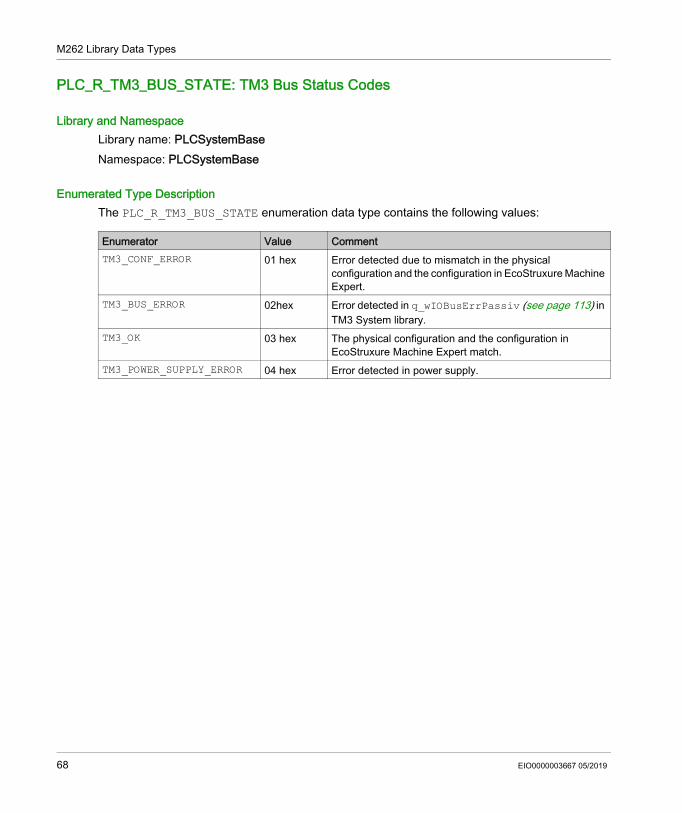
PLC_R_TM3_BUS_STATE: TM3 Bus Status Codes
Library and NamespaceLibrary name: PLCSystemBaseNamespace: PLCSystemBase
Enumerated Type DescriptionThe PLC_R_TM3_BUS_STATE enumeration data type contains the following values:
Enumerator Value CommentTM3_CONF_ERROR 01 hex Error detected due to mismatch in the physical
configuration and the configuration in EcoStruxure Machine Expert.
TM3_BUS_ERROR 02hex Error detected in q_wIOBusErrPassiv (see page 113) in TM3 System library.
TM3_OK 03 hex The physical configuration and the configuration in EcoStruxure Machine Expert match.
TM3_POWER_SUPPLY_ERROR 04 hex Error detected in power supply.
68 EIO0000003667 05/2019
M262 Library Data Types
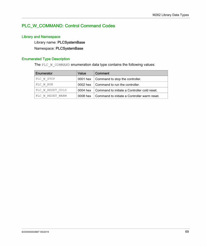
PLC_W_COMMAND: Control Command Codes
Library and NamespaceLibrary name: PLCSystemBaseNamespace: PLCSystemBase
Enumerated Type DescriptionThe PLC_W_COMMAND enumeration data type contains the following values:
Enumerator Value CommentPLC_W_STOP 0001 hex Command to stop the controller.PLC_W_RUN 0002 hex Command to run the controller.PLC_W_RESET_COLD 0004 hex Command to initiate a Controller cold reset.PLC_W_RESET_WARM 0008 hex Command to initiate a Controller warm reset.
EIO0000003667 05/2019 69
M262 Library Data Types
DataFileCopy System Variables Data Types
Section 3.2DataFileCopy System Variables Data Types
OverviewThis section lists and describes the system variable data types included in the DataFileCopy structures.
What Is in This Section?This section contains the following topics:
Topic PageDataFileCopyError: Detected Error Codes 71DataFileCopyLocation: Location Codes 72
70 EIO0000003667 05/2019
M262 Library Data Types
DataFileCopyError: Detected Error Codes
Library and NamespaceLibrary name: PLCSystemBaseNamespace: PLCSystemBase
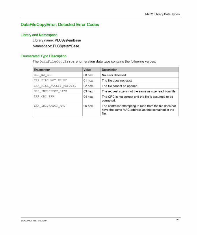
Enumerated Type DescriptionThe DataFileCopyError enumeration data type contains the following values:
Enumerator Value DescriptionERR_NO_ERR 00 hex No error detected.ERR_FILE_NOT_FOUND 01 hex The file does not exist.ERR_FILE_ACCESS_REFUSED 02 hex The file cannot be opened.ERR_INCORRECT_SIZE 03 hex The request size is not the same as size read from file.ERR_CRC_ERR 04 hex The CRC is not correct and the file is assumed to be
corrupted.ERR_INCORRECT_MAC 05 hex The controller attempting to read from the file does not
have the same MAC address as that contained in the file.
EIO0000003667 05/2019 71
M262 Library Data Types
DataFileCopyLocation: Location Codes
Library and NamespaceLibrary name: PLCSystemBaseNamespace: PLCSystemBase
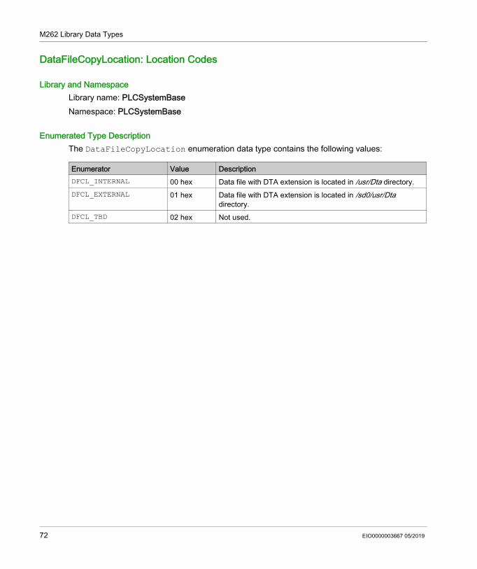
Enumerated Type DescriptionThe DataFileCopyLocation enumeration data type contains the following values:
Enumerator Value DescriptionDFCL_INTERNAL 00 hex Data file with DTA extension is located in /usr/Dta directory.DFCL_EXTERNAL 01 hex Data file with DTA extension is located in /sd0/usr/Dta
directory.DFCL_TBD 02 hex Not used.
72 EIO0000003667 05/2019
M262 Library Data Types
ExecScript System Variables Data Types
Section 3.3ExecScript System Variables Data Types
ExecuteScriptError: Detected Error Codes
Library and NamespaceLibrary name: PLCSystemBaseNamespace: PLCSystemBase
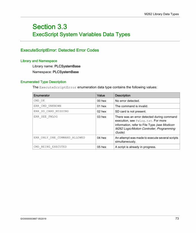
Enumerated Type DescriptionThe ExecuteScriptError enumeration data type contains the following values:
Enumerator Value DescriptionCMD_OK 00 hex No error detected.ERR_CMD_UNKNOWN 01 hex The command is invalid.ERR_SD_CARD_MISSING 02 hex SD card is not present.ERR_SEE_FWLOG 03 hex There was an error detected during command
execution, see FwLog.txt. For more information, refer to File Type (see Modicon M262 Logic/Motion Controller, Programming Guide).
ERR_ONLY_ONE_COMMAND_ALLOWED 04 hex An attempt was made to execute several scripts simultaneously.
CMD_BEING_EXECUTED 05 hex A script is already in progress.
EIO0000003667 05/2019 73
M262 Library Data Types
ETH_RW System Variables Data Types
Section 3.4ETH_RW System Variables Data Types
OverviewThis section lists and describes the system variable data types included in the ETH_R and ETH_W structures.
What Is in This Section?This section contains the following topics:
Topic PageETH_R_FRAME_PROTOCOL: Frame Transmission Protocol Codes 75ETH_R_IPFORWARDING: IP Forwarding 76ETH_R_IP_MODE: IP Address Source Codes 77ETH_R_ITF_STRUCT: Ethernet Interface Parameters 78ETH_R_PORT_DUPLEX_STATUS: Transmission Mode Codes 80ETH_R_PORT_IP_STATUS: Ethernet TCP/IP Port Status Codes 81ETH_R_PORT_LINK_STATUS: Communication Link Status Codes 82ETH_R_PORT_SPEED: Communication Speed of the Ethernet Port Codes 83ETH_R_RUN_IDLE: Ethernet/IP Run and Idle States Codes 84
74 EIO0000003667 05/2019
M262 Library Data Types
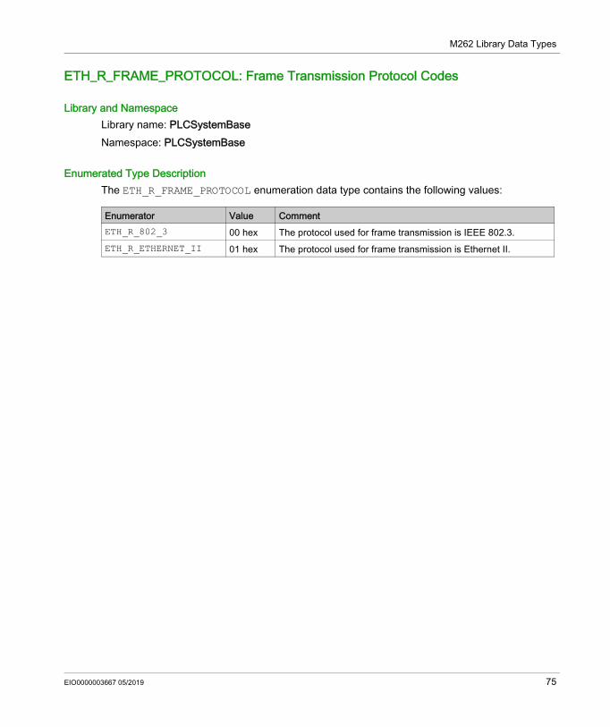
ETH_R_FRAME_PROTOCOL: Frame Transmission Protocol Codes
Library and NamespaceLibrary name: PLCSystemBaseNamespace: PLCSystemBase
Enumerated Type DescriptionThe ETH_R_FRAME_PROTOCOL enumeration data type contains the following values:
Enumerator Value CommentETH_R_802_3 00 hex The protocol used for frame transmission is IEEE 802.3.ETH_R_ETHERNET_II 01 hex The protocol used for frame transmission is Ethernet II.
EIO0000003667 05/2019 75
M262 Library Data Types
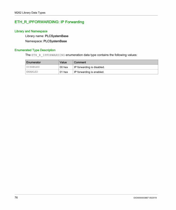
ETH_R_IPFORWARDING: IP Forwarding
Library and NamespaceLibrary name: PLCSystemBaseNamespace: PLCSystemBase
Enumerated Type DescriptionThe ETH_R_IPFORWARDING enumeration data type contains the following values:
Enumerator Value CommentDISABLED 00 hex IP forwarding is disabled.ENABLED 01 hex IP forwarding is enabled.
76 EIO0000003667 05/2019
M262 Library Data Types
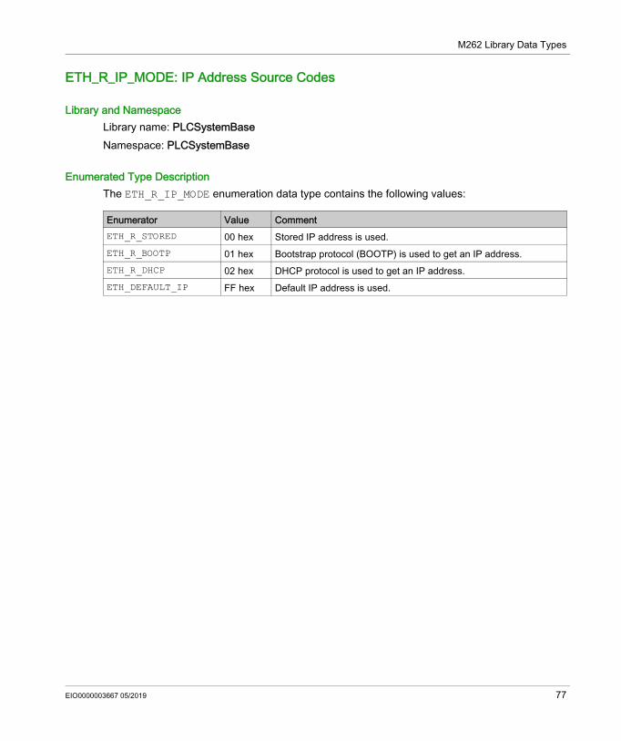
ETH_R_IP_MODE: IP Address Source Codes
Library and NamespaceLibrary name: PLCSystemBaseNamespace: PLCSystemBase
Enumerated Type DescriptionThe ETH_R_IP_MODE enumeration data type contains the following values:
Enumerator Value CommentETH_R_STORED 00 hex Stored IP address is used.ETH_R_BOOTP 01 hex Bootstrap protocol (BOOTP) is used to get an IP address.ETH_R_DHCP 02 hex DHCP protocol is used to get an IP address.ETH_DEFAULT_IP FF hex Default IP address is used.
EIO0000003667 05/2019 77
M262 Library Data Types
ETH_R_ITF_STRUCT: Ethernet Interface Parameters
Library and NamespaceLibrary name: PLCSystemBaseNamespace: PLCSystemBase
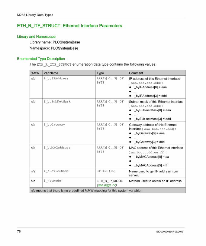
Enumerated Type DescriptionThe ETH_R_ITF_STRUCT enumeration data type contains the following values:
%MW Var Name Type Commentn/a i_byIPAddress ARRAY[0..3] OF
BYTEIP address of this Ethernet interface [aaa.bbb.ccc.ddd]: i_byIPAddress[0] = aaa ... i_byIPAddress[3] = ddd
n/a i_bySubNetMask ARRAY[0..3] OF BYTE
Subnet mask of this Ethernet interface [aaa.bbb.ccc.ddd]: i_bySub-netMask[0] = aaa ... i_bySub-netMask[3] = ddd
n/a i_byGateway ARRAY[0..3] OF BYTE
Gateway address of this Ethernet interface [aaa.bbb.ccc.ddd]: i_byGateway[0] = aaa ... i_byGateway[3] = ddd
n/a i_byMACAddress ARRAY[0..5] OF BYTE
MAC address of this Ethernet interface [aa.bb.cc.dd.ee.ff]: i_byMACAddress[0] = aa ... i_byMACAddress[5] = ff
n/a i_sDeviceName STRING(15) Name used to get IP address from server.
n/a i_wIpMode ETH_R_IP_MODE (see page 77)
Method used to obtain an IP address.
n/a means that there is no predefined %MW mapping for this system variable.
78 EIO0000003667 05/2019
M262 Library Data Types
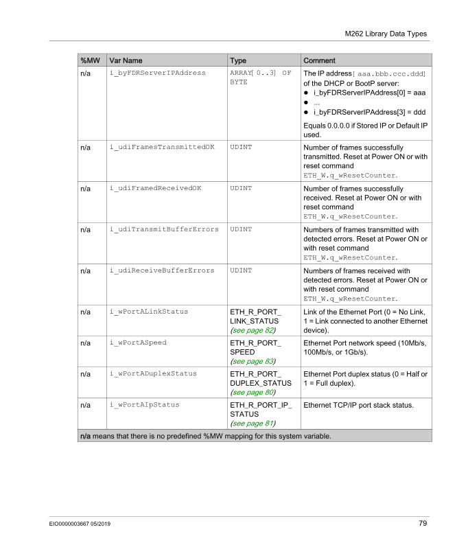
n/a i_byFDRServerIPAddress ARRAY[0..3] OF BYTE
The IP address [aaa.bbb.ccc.ddd] of the DHCP or BootP server: i_byFDRServerIPAddress[0] = aaa ... i_byFDRServerIPAddress[3] = ddd
Equals 0.0.0.0 if Stored IP or Default IP used.
n/a i_udiFramesTransmittedOK UDINT Number of frames successfully transmitted. Reset at Power ON or with reset command ETH_W.q_wResetCounter.
n/a i_udiFramedReceivedOK UDINT Number of frames successfully received. Reset at Power ON or with reset command ETH_W.q_wResetCounter.
n/a i_udiTransmitBufferErrors UDINT Numbers of frames transmitted with detected errors. Reset at Power ON or with reset command ETH_W.q_wResetCounter.
n/a i_udiReceiveBufferErrors UDINT Numbers of frames received with detected errors. Reset at Power ON or with reset command ETH_W.q_wResetCounter.
n/a i_wPortALinkStatus ETH_R_PORT_ LINK_STATUS (see page 82)
Link of the Ethernet Port (0 = No Link, 1 = Link connected to another Ethernet device).
n/a i_wPortASpeed ETH_R_PORT_ SPEED (see page 83)
Ethernet Port network speed (10Mb/s, 100Mb/s, or 1Gb/s).
n/a i_wPortADuplexStatus ETH_R_PORT_ DUPLEX_STATUS (see page 80)
Ethernet Port duplex status (0 = Half or 1 = Full duplex).
n/a i_wPortAIpStatus ETH_R_PORT_IP_ STATUS (see page 81)
Ethernet TCP/IP port stack status.
%MW Var Name Type Comment
n/a means that there is no predefined %MW mapping for this system variable.
EIO0000003667 05/2019 79
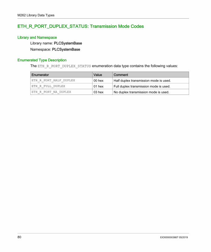
M262 Library Data Types
ETH_R_PORT_DUPLEX_STATUS: Transmission Mode Codes
Library and NamespaceLibrary name: PLCSystemBaseNamespace: PLCSystemBase
Enumerated Type DescriptionThe ETH_R_PORT_DUPLEX_STATUS enumeration data type contains the following values:
Enumerator Value CommentETH_R_PORT_HALF_DUPLEX 00 hex Half duplex transmission mode is used.ETH_R_FULL_DUPLEX 01 hex Full duplex transmission mode is used.ETH_R_PORT_NA_DUPLEX 03 hex No duplex transmission mode is used.
80 EIO0000003667 05/2019
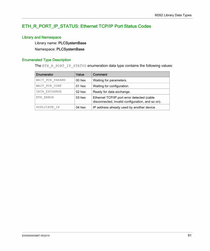
M262 Library Data Types
ETH_R_PORT_IP_STATUS: Ethernet TCP/IP Port Status Codes
Library and NamespaceLibrary name: PLCSystemBaseNamespace: PLCSystemBase
Enumerated Type DescriptionThe ETH_R_PORT_IP_STATUS enumeration data type contains the following values:
Enumerator Value CommentWAIT_FOR_PARAMS 00 hex Waiting for parameters.WAIT_FOR_CONF 01 hex Waiting for configuration.DATA_EXCHANGE 02 hex Ready for data exchange.ETH_ERROR 03 hex Ethernet TCP/IP port error detected (cable
disconnected, invalid configuration, and so on).DUPLICATE_IP 04 hex IP address already used by another device.
EIO0000003667 05/2019 81
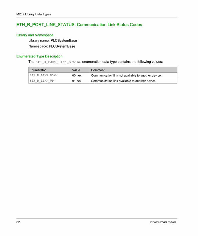
M262 Library Data Types
ETH_R_PORT_LINK_STATUS: Communication Link Status Codes
Library and NamespaceLibrary name: PLCSystemBaseNamespace: PLCSystemBase
Enumerated Type DescriptionThe ETH_R_PORT_LINK_STATUS enumeration data type contains the following values:
Enumerator Value CommentETH_R_LINK_DOWN 00 hex Communication link not available to another device.ETH_R_LINK_UP 01 hex Communication link available to another device.
82 EIO0000003667 05/2019
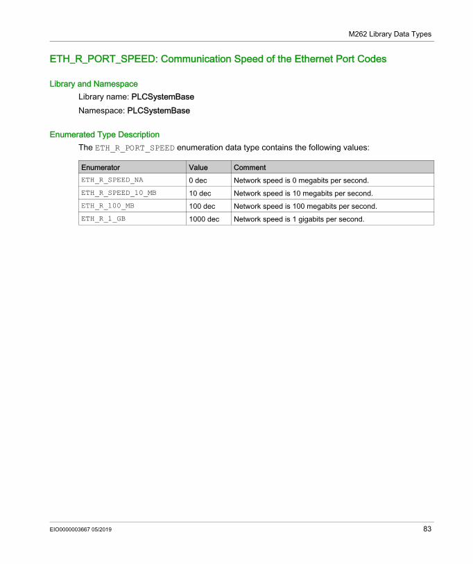
M262 Library Data Types
ETH_R_PORT_SPEED: Communication Speed of the Ethernet Port Codes
Library and NamespaceLibrary name: PLCSystemBaseNamespace: PLCSystemBase
Enumerated Type DescriptionThe ETH_R_PORT_SPEED enumeration data type contains the following values:
Enumerator Value CommentETH_R_SPEED_NA 0 dec Network speed is 0 megabits per second.ETH_R_SPEED_10_MB 10 dec Network speed is 10 megabits per second.ETH_R_100_MB 100 dec Network speed is 100 megabits per second.ETH_R_1_GB 1000 dec Network speed is 1 gigabits per second.
EIO0000003667 05/2019 83
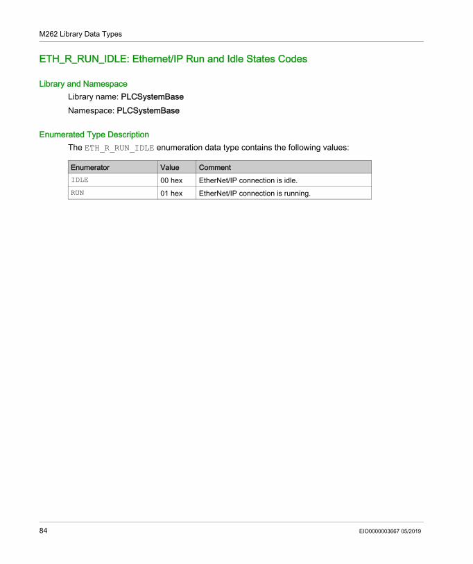
M262 Library Data Types
ETH_R_RUN_IDLE: Ethernet/IP Run and Idle States Codes
Library and NamespaceLibrary name: PLCSystemBaseNamespace: PLCSystemBase
Enumerated Type DescriptionThe ETH_R_RUN_IDLE enumeration data type contains the following values:
Enumerator Value CommentIDLE 00 hex EtherNet/IP connection is idle.RUN 01 hex EtherNet/IP connection is running.
84 EIO0000003667 05/2019
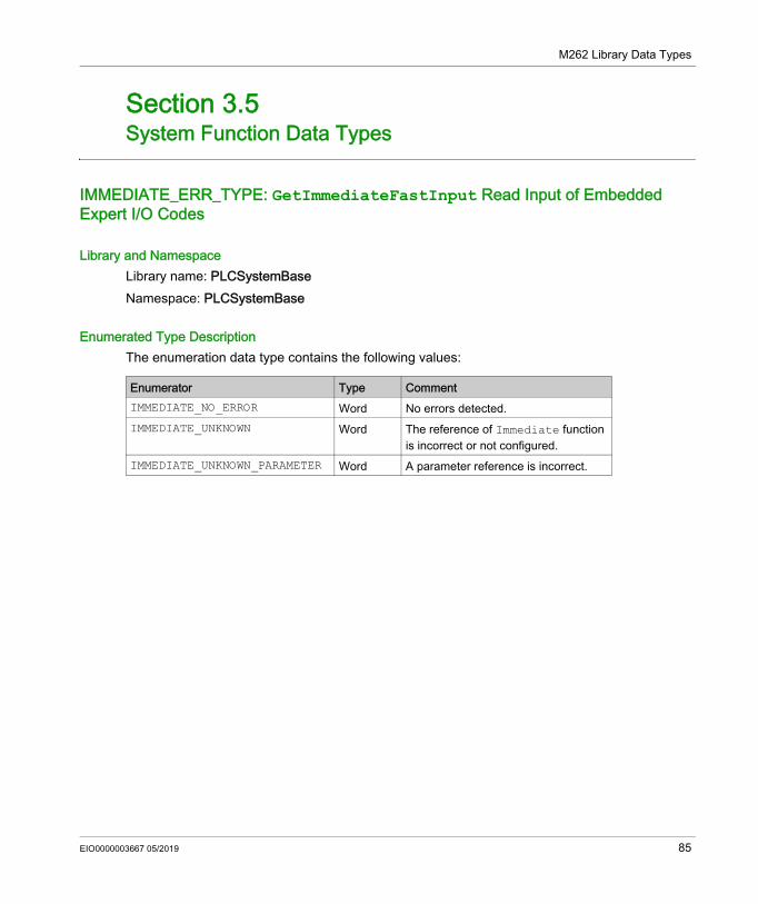
M262 Library Data Types
System Function Data Types
Section 3.5System Function Data Types
IMMEDIATE_ERR_TYPE: GetImmediateFastInput Read Input of Embedded Expert I/O Codes
Library and NamespaceLibrary name: PLCSystemBaseNamespace: PLCSystemBase
Enumerated Type DescriptionThe enumeration data type contains the following values:
Enumerator Type CommentIMMEDIATE_NO_ERROR Word No errors detected.IMMEDIATE_UNKNOWN Word The reference of Immediate function
is incorrect or not configured.IMMEDIATE_UNKNOWN_PARAMETER Word A parameter reference is incorrect.
EIO0000003667 05/2019 85

M262 Library Data Types
86 EIO0000003667 05/2019
Modicon M262 Logic/Motion ControllerSysLogEIO0000003667 05/2019
SysLog
Part IISysLog
EIO0000003667 05/2019 87

SysLog
88 EIO0000003667 05/2019
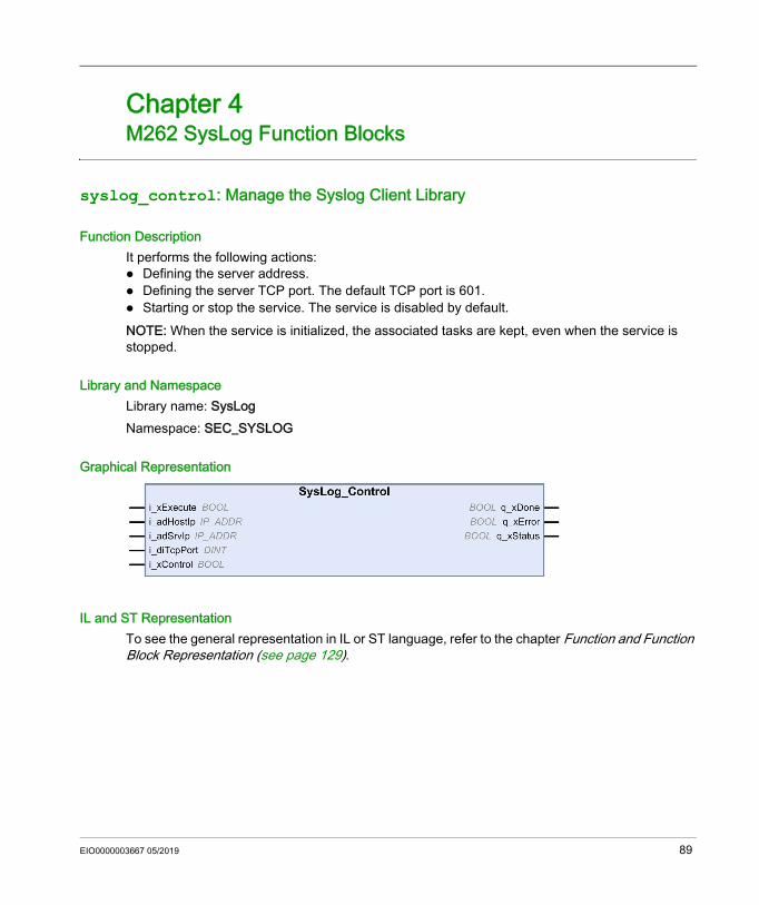
Modicon M262 Logic/Motion ControllerM262 Syslog Function BlocksEIO0000003667 05/2019
M262 SysLog Function Blocks
Chapter 4M262 SysLog Function Blocks
syslog_control: Manage the Syslog Client Library
Function DescriptionIt performs the following actions: Defining the server address. Defining the server TCP port. The default TCP port is 601. Starting or stop the service. The service is disabled by default.NOTE: When the service is initialized, the associated tasks are kept, even when the service is stopped.
Library and NamespaceLibrary name: SysLogNamespace: SEC_SYSLOG
Graphical Representation
IL and ST RepresentationTo see the general representation in IL or ST language, refer to the chapter Function and Function Block Representation (see page 129).
EIO0000003667 05/2019 89
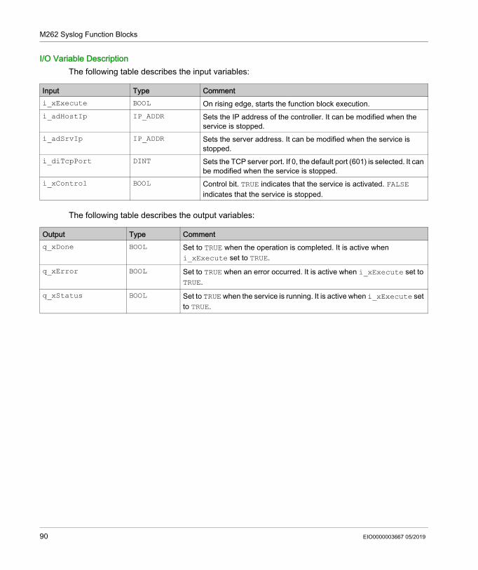
M262 Syslog Function Blocks
I/O Variable DescriptionThe following table describes the input variables:
The following table describes the output variables:
Input Type Commenti_xExecute BOOL On rising edge, starts the function block execution.i_adHostIp IP_ADDR Sets the IP address of the controller. It can be modified when the
service is stopped.i_adSrvIp IP_ADDR Sets the server address. It can be modified when the service is
stopped.i_diTcpPort DINT Sets the TCP server port. If 0, the default port (601) is selected. It can
be modified when the service is stopped.i_xControl BOOL Control bit. TRUE indicates that the service is activated. FALSE
indicates that the service is stopped.
Output Type Commentq_xDone BOOL Set to TRUE when the operation is completed. It is active when
i_xExecute set to TRUE.q_xError BOOL Set to TRUE when an error occurred. It is active when i_xExecute set to
TRUE.q_xStatus BOOL Set to TRUE when the service is running. It is active when i_xExecute set
to TRUE.
90 EIO0000003667 05/2019
Modicon M262 Logic/Motion ControllerSerialLine SystemEIO0000003667 05/2019
SerialLine System
Part IIISerialLine System
EIO0000003667 05/2019 91

SerialLine System
92 EIO0000003667 05/2019
Modicon M262 Logic/Motion ControllerM262 Serial Line System VariablesEIO0000003667 05/2019
M262 Serial Line System Variables
Chapter 5M262 Serial Line System Variables
OverviewThis chapter describes the Serial Line system variables of the M262 PLCSystem library.
What Is in This Chapter?This chapter contains the following topics:
Topic PageSERIAL_R_STRUCT: Serial Line Diagnostic Variables 94
SERIAL_W_STRUCT: Serial Line Diagnostic Variables 95
EIO0000003667 05/2019 93
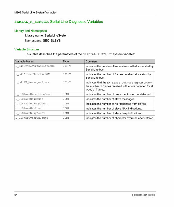
M262 Serial Line System Variables
SERIAL_R_STRUCT: Serial Line Diagnostic Variables
Library and NamespaceLibrary name: SerialLineSystemNamespace: SEC_SLSYS
Variable StructureThis table describes the parameters of the SERDIAL_R_STRUCT system variable:
Variable Name Type Commenti_udiFramesTransmittedOK UDINT Indicates the number of frames transmitted since start by
Serial Line bus.i_udiFramesReceivedOK UDINT Indicates the number of frames received since start by
Serial Line bus.i_udiRX_MessagesError UDINT Indicates that the RX Error Counter register counts
the number of frames received with errors detected for all types of frames.
i_uiSlaveExceptionCount UINT Indicates the number of bus exception errors detected.i_uiSlaveMsgCount UINT Indicates the number of slave messages.i_uiSlaveNoRespCount UINT Indicates the number of no responses from slaves.i_uiSlaveNakCount UINT Indicates the number of slave NAK indications.i_uiSlaveBusyCount UINT Indicates the number of slave busy indications.i_uiCharOverrunCount UINT Indicates the number of character overruns encountered.
94 EIO0000003667 05/2019
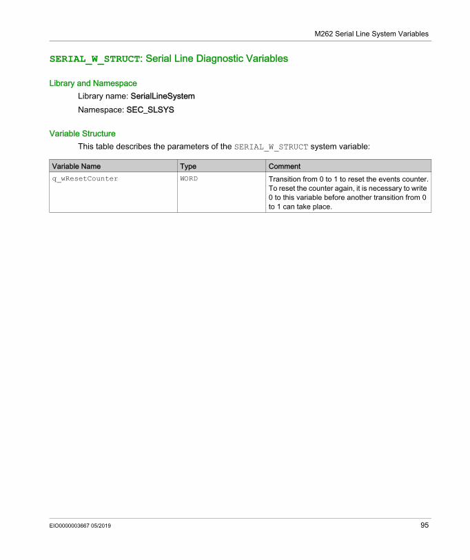
M262 Serial Line System Variables
SERIAL_W_STRUCT: Serial Line Diagnostic Variables
Library and NamespaceLibrary name: SerialLineSystemNamespace: SEC_SLSYS
Variable StructureThis table describes the parameters of the SERIAL_W_STRUCT system variable:
Variable Name Type Commentq_wResetCounter WORD Transition from 0 to 1 to reset the events counter.
To reset the counter again, it is necessary to write 0 to this variable before another transition from 0 to 1 can take place.
EIO0000003667 05/2019 95
M262 Serial Line System Variables
96 EIO0000003667 05/2019
Modicon M262 Logic/Motion ControllerTM3 SystemEIO0000003667 05/2019
TM3 System
Part IVTM3 System
IntroductionThis part describes the TM3 System Library.
What Is in This Part?This part contains the following chapters:
Chapter Chapter Name Page6 TM3 System Variables 997 TM3 System Functions 1018 TM3 System Data Types 109
EIO0000003667 05/2019 97

TM3 System
98 EIO0000003667 05/2019
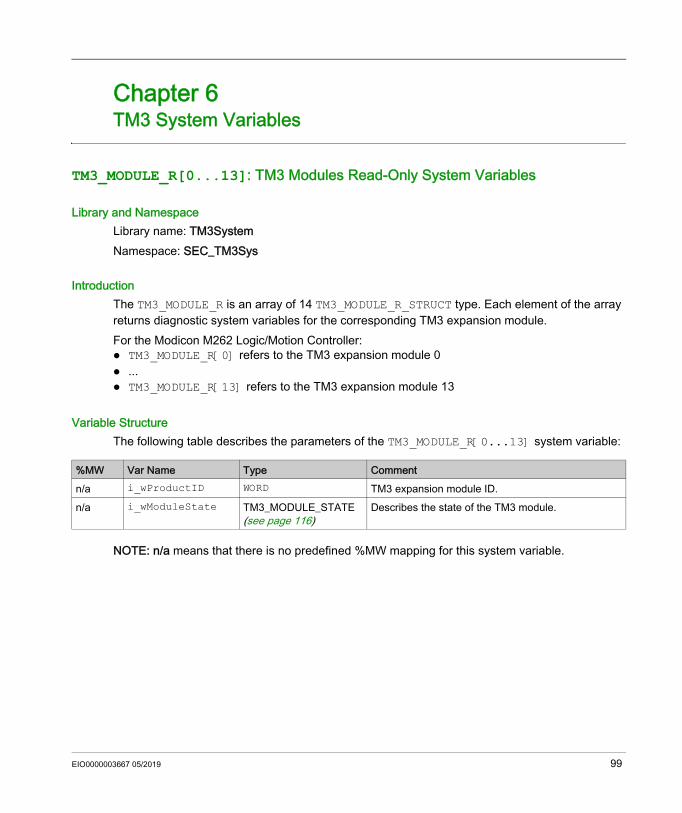
Modicon M262 Logic/Motion ControllerTM3 System VariablesEIO0000003667 05/2019
TM3 System Variables
Chapter 6TM3 System Variables
TM3_MODULE_R[0...13]: TM3 Modules Read-Only System Variables
Library and NamespaceLibrary name: TM3SystemNamespace: SEC_TM3Sys
IntroductionThe TM3_MODULE_R is an array of 14 TM3_MODULE_R_STRUCT type. Each element of the array returns diagnostic system variables for the corresponding TM3 expansion module.For the Modicon M262 Logic/Motion Controller: TM3_MODULE_R[0] refers to the TM3 expansion module 0 ... TM3_MODULE_R[13] refers to the TM3 expansion module 13
Variable StructureThe following table describes the parameters of the TM3_MODULE_R[0...13] system variable:
NOTE: n/a means that there is no predefined %MW mapping for this system variable.
%MW Var Name Type Commentn/a i_wProductID WORD TM3 expansion module ID.n/a i_wModuleState TM3_MODULE_STATE
(see page 116)Describes the state of the TM3 module.
EIO0000003667 05/2019 99

TM3 System Variables
100 EIO0000003667 05/2019
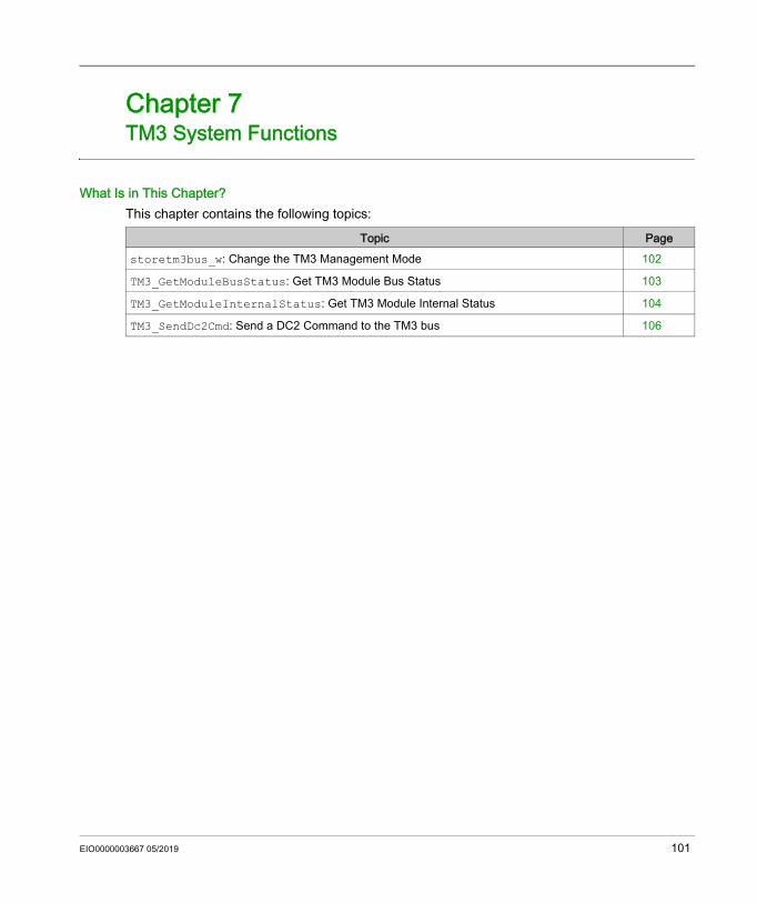
Modicon M262 Logic/Motion ControllerTM3 System FunctionsEIO0000003667 05/2019
TM3 System Functions
Chapter 7TM3 System Functions
What Is in This Chapter?This chapter contains the following topics:
Topic Pagestoretm3bus_w: Change the TM3 Management Mode 102
TM3_GetModuleBusStatus: Get TM3 Module Bus Status 103
TM3_GetModuleInternalStatus: Get TM3 Module Internal Status 104
TM3_SendDc2Cmd: Send a DC2 Command to the TM3 bus 106
EIO0000003667 05/2019 101
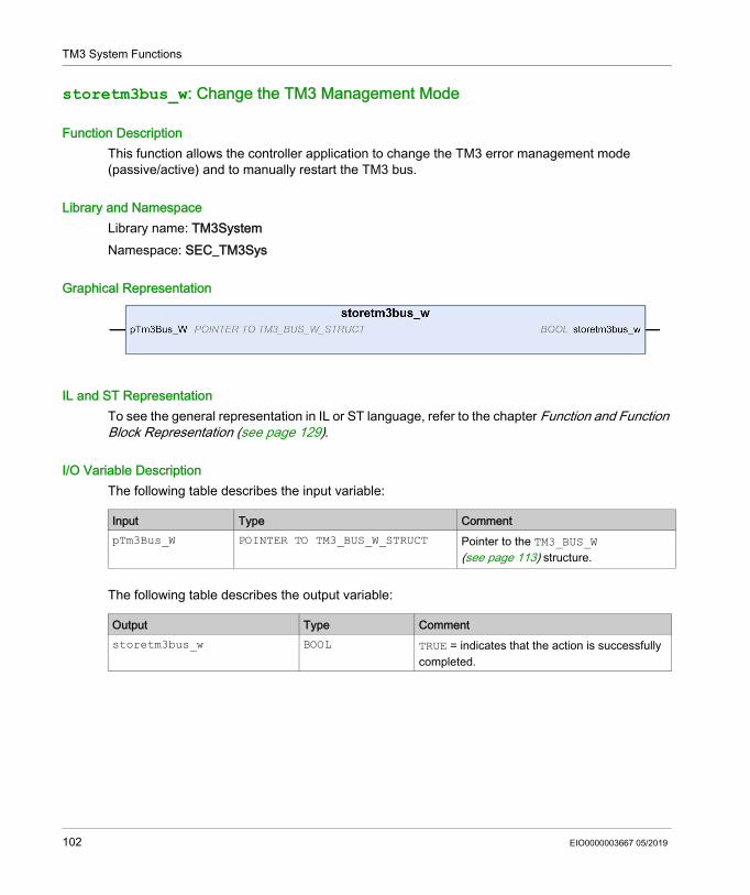
TM3 System Functions
storetm3bus_w: Change the TM3 Management Mode
Function DescriptionThis function allows the controller application to change the TM3 error management mode (passive/active) and to manually restart the TM3 bus.
Library and NamespaceLibrary name: TM3SystemNamespace: SEC_TM3Sys
Graphical Representation
IL and ST RepresentationTo see the general representation in IL or ST language, refer to the chapter Function and Function Block Representation (see page 129).
I/O Variable DescriptionThe following table describes the input variable:
The following table describes the output variable:
Input Type CommentpTm3Bus_W POINTER TO TM3_BUS_W_STRUCT Pointer to the TM3_BUS_W
(see page 113) structure.
Output Type Commentstoretm3bus_w BOOL TRUE = indicates that the action is successfully
completed.
102 EIO0000003667 05/2019
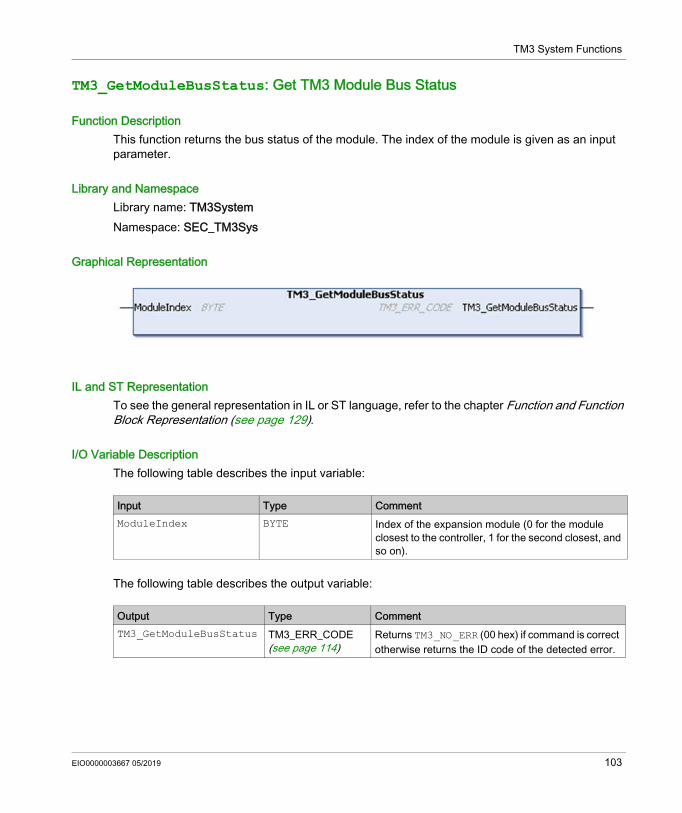
TM3 System Functions
TM3_GetModuleBusStatus: Get TM3 Module Bus Status
Function DescriptionThis function returns the bus status of the module. The index of the module is given as an input parameter.
Library and NamespaceLibrary name: TM3SystemNamespace: SEC_TM3Sys
Graphical Representation
IL and ST RepresentationTo see the general representation in IL or ST language, refer to the chapter Function and Function Block Representation (see page 129).
I/O Variable DescriptionThe following table describes the input variable:
The following table describes the output variable:
Input Type CommentModuleIndex BYTE Index of the expansion module (0 for the module
closest to the controller, 1 for the second closest, and so on).
Output Type CommentTM3_GetModuleBusStatus TM3_ERR_CODE
(see page 114)Returns TM3_NO_ERR (00 hex) if command is correct otherwise returns the ID code of the detected error.
EIO0000003667 05/2019 103
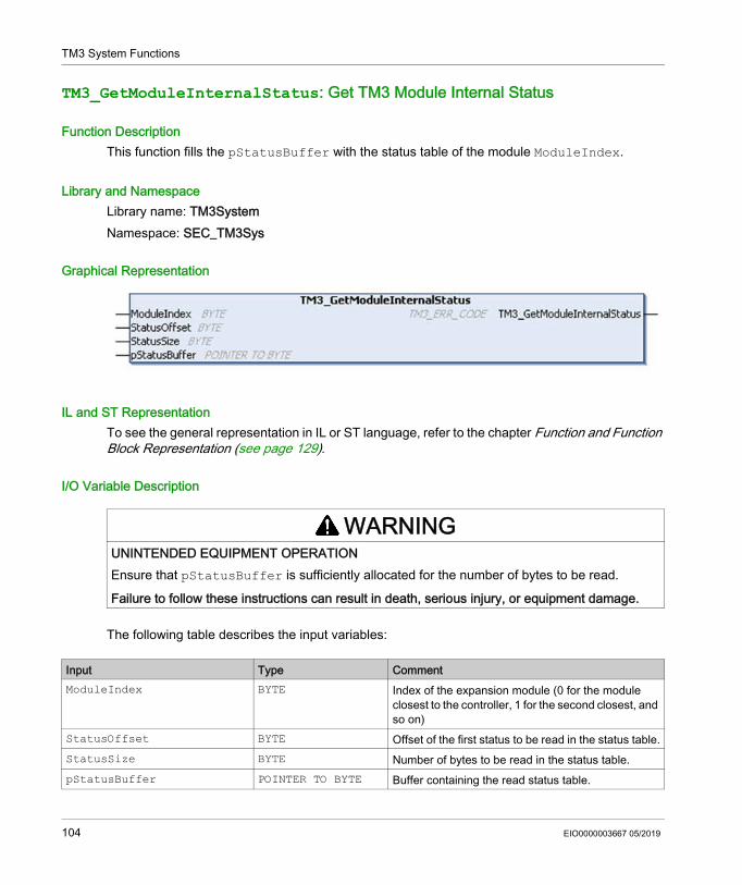
TM3 System Functions
TM3_GetModuleInternalStatus: Get TM3 Module Internal Status
Function DescriptionThis function fills the pStatusBuffer with the status table of the module ModuleIndex.
Library and NamespaceLibrary name: TM3SystemNamespace: SEC_TM3Sys
Graphical Representation
IL and ST RepresentationTo see the general representation in IL or ST language, refer to the chapter Function and Function Block Representation (see page 129).
I/O Variable Description
The following table describes the input variables:
WARNINGUNINTENDED EQUIPMENT OPERATIONEnsure that pStatusBuffer is sufficiently allocated for the number of bytes to be read.
Failure to follow these instructions can result in death, serious injury, or equipment damage.
Input Type CommentModuleIndex BYTE Index of the expansion module (0 for the module
closest to the controller, 1 for the second closest, and so on)
StatusOffset BYTE Offset of the first status to be read in the status table.StatusSize BYTE Number of bytes to be read in the status table.pStatusBuffer POINTER TO BYTE Buffer containing the read status table.
104 EIO0000003667 05/2019
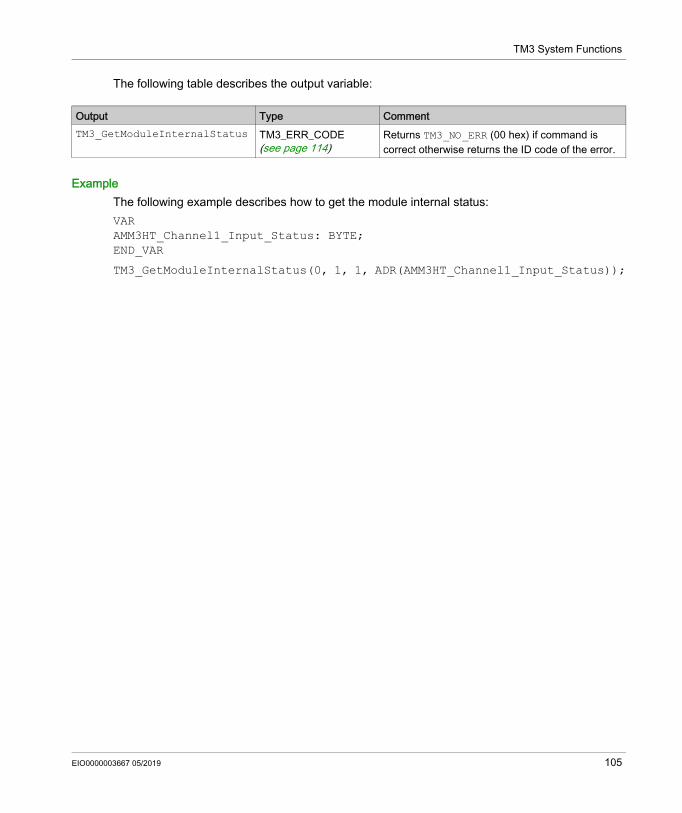
TM3 System Functions
The following table describes the output variable:
ExampleThe following example describes how to get the module internal status:VARAMM3HT_Channel1_Input_Status: BYTE;END_VAR
TM3_GetModuleInternalStatus(0, 1, 1, ADR(AMM3HT_Channel1_Input_Status));
Output Type CommentTM3_GetModuleInternalStatus TM3_ERR_CODE
(see page 114)Returns TM3_NO_ERR (00 hex) if command is correct otherwise returns the ID code of the error.
EIO0000003667 05/2019 105

TM3 System Functions
TM3_SendDc2Cmd: Send a DC2 Command to the TM3 bus
Function DescriptionThis function sends a module configuration command to the TM3 bus.
Library and NamespaceLibrary name: TM3SystemNamespace: SEC_TM3Sys
Graphical Representation
IL and ST RepresentationTo see the general representation in IL or ST language, refer to the chapter Function and Function Block Representation (see page 129).
I/O Variable DescriptionThe following table describes the input variables:
Input Type CommentModuleIndex BYTE Index of the expansion module (0 for the module closest to the
controller, 1 for the second closest, and so on)RWtype BYTE Access type
0: read 1: write 2: read/write
ByteSize BYTE Number of bytes to access (1 to 127)HeadAddr BYTE Address within the block to be accessed (0 to 127)BlockNum BYTE Block to be accessed (0 to 63)pInData POINTER TO BYTE Pointer to the data buffer filled by the TM3 module. If no data
expected: 0.pOutData POINTER TO BYTE Pointer to the data buffer to be written to the TM3 module. If no
data buffer to write: 0.
106 EIO0000003667 05/2019
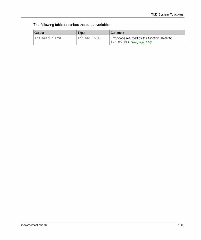
TM3 System Functions
The following table describes the output variable:
Output Type CommentTM3_SendDc2Cmd TM3_ERR_CODE Error code returned by the function. Refer to
TM3_NO_ERR (see page 114).
EIO0000003667 05/2019 107

TM3 System Functions
108 EIO0000003667 05/2019
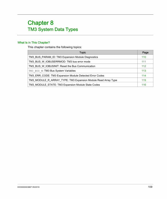
Modicon M262 Logic/Motion ControllerTM3 System Data TypesEIO0000003667 05/2019
TM3 System Data Types
Chapter 8TM3 System Data Types
What Is in This Chapter?This chapter contains the following topics:
Topic PageTM3_BUS_PARAM_ID: TM3 Expansion Module Diagnostics 110TM3_BUS_W_IOBUSERRMOD: TM3 bus error mode 111TM3_BUS_W_IOBUSINIT: Reset the Bus Communication 112TM3_BUS_W: TM3 Bus System Variables 113
TM3_ERR_CODE: TM3 Expansion Module Detected Error Codes 114TM3_MODULE_R_ARRAY_TYPE: TM3 Expansion Module Read Array Type 115TM3_MODULE_STATE: TM3 Expansion Module State Codes 116
EIO0000003667 05/2019 109
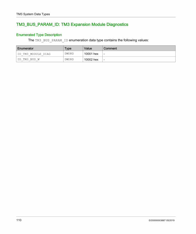
TM3 System Data Types
TM3_BUS_PARAM_ID: TM3 Expansion Module Diagnostics
Enumerated Type DescriptionThe TM3_BUS_PARAM_ID enumeration data type contains the following values:
Enumerator Type Value CommentID_TM3_MODULE_DIAG DWORD 10001 hex -ID_TM3_BUS_W DWORD 10002 hex -
110 EIO0000003667 05/2019
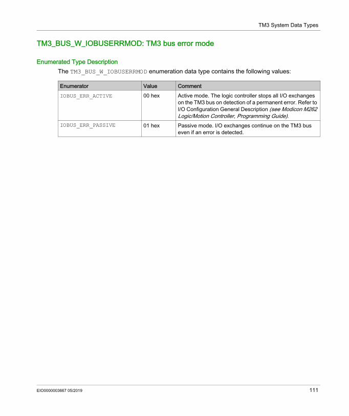
TM3 System Data Types
TM3_BUS_W_IOBUSERRMOD: TM3 bus error mode
Enumerated Type DescriptionThe TM3_BUS_W_IOBUSERRMOD enumeration data type contains the following values:
Enumerator Value CommentIOBUS_ERR_ACTIVE 00 hex Active mode. The logic controller stops all I/O exchanges
on the TM3 bus on detection of a permanent error. Refer to I/O Configuration General Description (see Modicon M262 Logic/Motion Controller, Programming Guide).
IOBUS_ERR_PASSIVE 01 hex Passive mode. I/O exchanges continue on the TM3 bus even if an error is detected.
EIO0000003667 05/2019 111
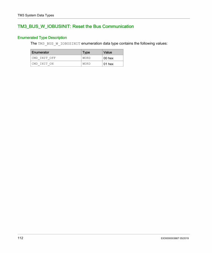
TM3 System Data Types
TM3_BUS_W_IOBUSINIT: Reset the Bus Communication
Enumerated Type DescriptionThe TM3_BUS_W_IOBUSINIT enumeration data type contains the following values:
Enumerator Type ValueCMD_INIT_OFF WORD 00 hexCMD_INIT_ON WORD 01 hex
112 EIO0000003667 05/2019
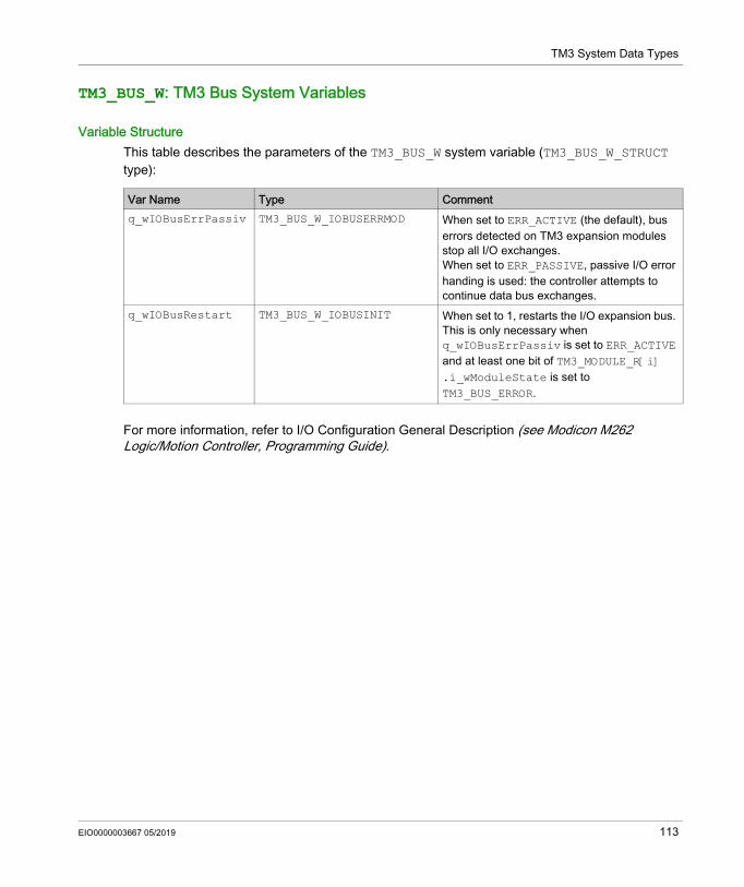
TM3 System Data Types
TM3_BUS_W: TM3 Bus System Variables
Variable StructureThis table describes the parameters of the TM3_BUS_W system variable (TM3_BUS_W_STRUCT type):
For more information, refer to I/O Configuration General Description (see Modicon M262 Logic/Motion Controller, Programming Guide).
Var Name Type Commentq_wIOBusErrPassiv TM3_BUS_W_IOBUSERRMOD When set to ERR_ACTIVE (the default), bus
errors detected on TM3 expansion modules stop all I/O exchanges.When set to ERR_PASSIVE, passive I/O error handing is used: the controller attempts to continue data bus exchanges.
q_wIOBusRestart TM3_BUS_W_IOBUSINIT When set to 1, restarts the I/O expansion bus. This is only necessary when q_wIOBusErrPassiv is set to ERR_ACTIVE and at least one bit of TM3_MODULE_R[i] .i_wModuleState is set to TM3_BUS_ERROR.
EIO0000003667 05/2019 113
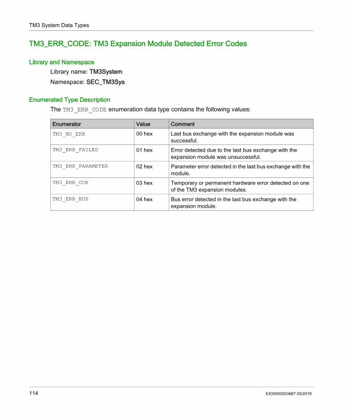
TM3 System Data Types
TM3_ERR_CODE: TM3 Expansion Module Detected Error Codes
Library and NamespaceLibrary name: TM3SystemNamespace: SEC_TM3Sys
Enumerated Type DescriptionThe TM3_ERR_CODE enumeration data type contains the following values:
Enumerator Value CommentTM3_NO_ERR 00 hex Last bus exchange with the expansion module was
successful.TM3_ERR_FAILED 01 hex Error detected due to the last bus exchange with the
expansion module was unsuccessful.TM3_ERR_PARAMETER 02 hex Parameter error detected in the last bus exchange with the
module.TM3_ERR_COK 03 hex Temporary or permanent hardware error detected on one
of the TM3 expansion modules.TM3_ERR_BUS 04 hex Bus error detected in the last bus exchange with the
expansion module.
114 EIO0000003667 05/2019
TM3 System Data Types
TM3_MODULE_R_ARRAY_TYPE: TM3 Expansion Module Read Array Type
Library and NamespaceLibrary name: TM3SystemNamespace: SEC_TM3Sys
DescriptionThe TM3_MODULE_R_ARRAY_TYPE is an array of 0...13 TM3_MODULE_R_STRUCT.
EIO0000003667 05/2019 115
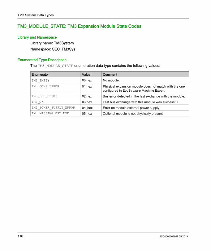
TM3 System Data Types
TM3_MODULE_STATE: TM3 Expansion Module State Codes
Library and NamespaceLibrary name: TM3SystemNamespace: SEC_TM3Sys
Enumerated Type DescriptionThe TM3_MODULE_STATE enumeration data type contains the following values:
Enumerator Value CommentTM3_EMPTY 00 hex No module.TM3_CONF_ERROR 01 hex Physical expansion module does not match with the one
configured in EcoStruxure Machine Expert.TM3_BUS_ERROR 02 hex Bus error detected in the last exchange with the module.TM3_OK 03 hex Last bus exchange with this module was successful.TM3_POWER_SUPPLY_ERROR 04_hex Error on module external power supply.TM3_MISSING_OPT_MOD 05 hex Optional module is not physically present.
116 EIO0000003667 05/2019
Modicon M262 Logic/Motion ControllerTMS SystemEIO0000003667 05/2019
TMS System
Part VTMS System
IntroductionThis part describes the TMS System Library.
What Is in This Part?This part contains the following chapters:
Chapter Chapter Name Page9 TMS System Variables 119
10 TMS System Data Types 123
EIO0000003667 05/2019 117

TMS System
118 EIO0000003667 05/2019
Modicon M262 Logic/Motion ControllerTMS System VariablesEIO0000003667 05/2019
TMS System Variables
Chapter 9TMS System Variables
OverviewThis chapter describes the system variables (see page 19) included in the TMS System Library.
What Is in This Chapter?This chapter contains the following topics:
Topic PageSTRUCT_TMS_BUS_DIAG: TMS Bus Diagnostic Error Codes 120STRUCT_TMS_MODULE_DIAG: TMS Expansion Module Diagnostic Error Codes 121
EIO0000003667 05/2019 119
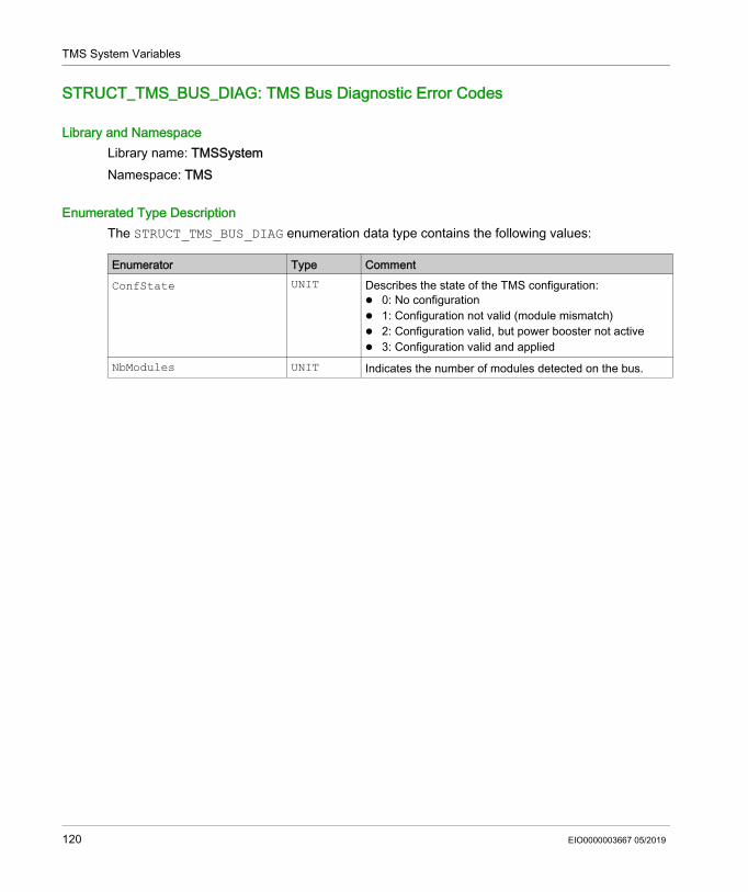
TMS System Variables
STRUCT_TMS_BUS_DIAG: TMS Bus Diagnostic Error Codes
Library and NamespaceLibrary name: TMSSystemNamespace: TMS
Enumerated Type DescriptionThe STRUCT_TMS_BUS_DIAG enumeration data type contains the following values:
Enumerator Type CommentConfState UNIT Describes the state of the TMS configuration:
0: No configuration 1: Configuration not valid (module mismatch) 2: Configuration valid, but power booster not active 3: Configuration valid and applied
NbModules UNIT Indicates the number of modules detected on the bus.
120 EIO0000003667 05/2019
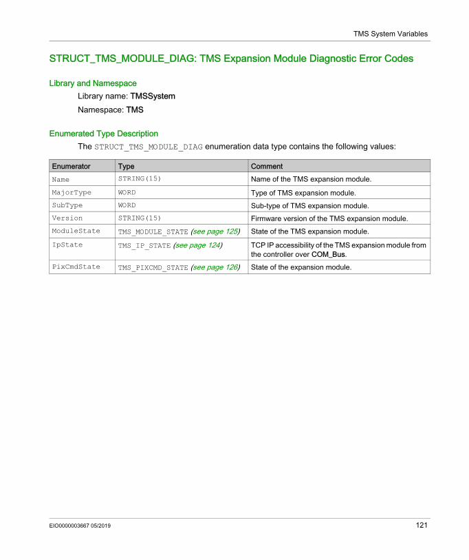
TMS System Variables
STRUCT_TMS_MODULE_DIAG: TMS Expansion Module Diagnostic Error Codes
Library and NamespaceLibrary name: TMSSystemNamespace: TMS
Enumerated Type DescriptionThe STRUCT_TMS_MODULE_DIAG enumeration data type contains the following values:
Enumerator Type CommentName STRING(15) Name of the TMS expansion module.MajorType WORD Type of TMS expansion module.SubType WORD Sub-type of TMS expansion module.Version STRING(15) Firmware version of the TMS expansion module.ModuleState TMS_MODULE_STATE (see page 125) State of the TMS expansion module.IpState TMS_IP_STATE (see page 124) TCP IP accessibility of the TMS expansion module from
the controller over COM_Bus.PixCmdState TMS_PIXCMD_STATE (see page 126) State of the expansion module.
EIO0000003667 05/2019 121

TMS System Variables
122 EIO0000003667 05/2019
Modicon M262 Logic/Motion ControllerTMS System Data TypesEIO0000003667 05/2019
TMS System Data Types
Chapter 10TMS System Data Types
What Is in This Chapter?This chapter contains the following topics:
Topic PageTMS_IP_STATE: TMS Expansion Module IP State 124TMS_MODULE_STATE: TMS Expansion Module State Codes 125TMS_PIXCMD_STATE: TMS Expansion Module PIXCMD State 126
EIO0000003667 05/2019 123
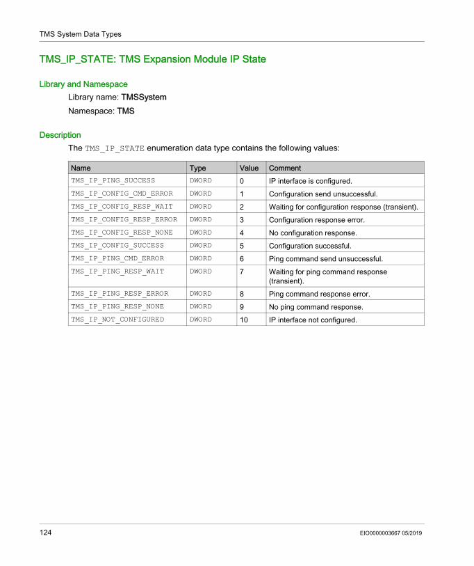
TMS System Data Types
TMS_IP_STATE: TMS Expansion Module IP State
Library and NamespaceLibrary name: TMSSystemNamespace: TMS
DescriptionThe TMS_IP_STATE enumeration data type contains the following values:
Name Type Value CommentTMS_IP_PING_SUCCESS DWORD 0 IP interface is configured.TMS_IP_CONFIG_CMD_ERROR DWORD 1 Configuration send unsuccessful.TMS_IP_CONFIG_RESP_WAIT DWORD 2 Waiting for configuration response (transient).TMS_IP_CONFIG_RESP_ERROR DWORD 3 Configuration response error.TMS_IP_CONFIG_RESP_NONE DWORD 4 No configuration response.TMS_IP_CONFIG_SUCCESS DWORD 5 Configuration successful.TMS_IP_PING_CMD_ERROR DWORD 6 Ping command send unsuccessful.TMS_IP_PING_RESP_WAIT DWORD 7 Waiting for ping command response
(transient).TMS_IP_PING_RESP_ERROR DWORD 8 Ping command response error.TMS_IP_PING_RESP_NONE DWORD 9 No ping command response.TMS_IP_NOT_CONFIGURED DWORD 10 IP interface not configured.
124 EIO0000003667 05/2019
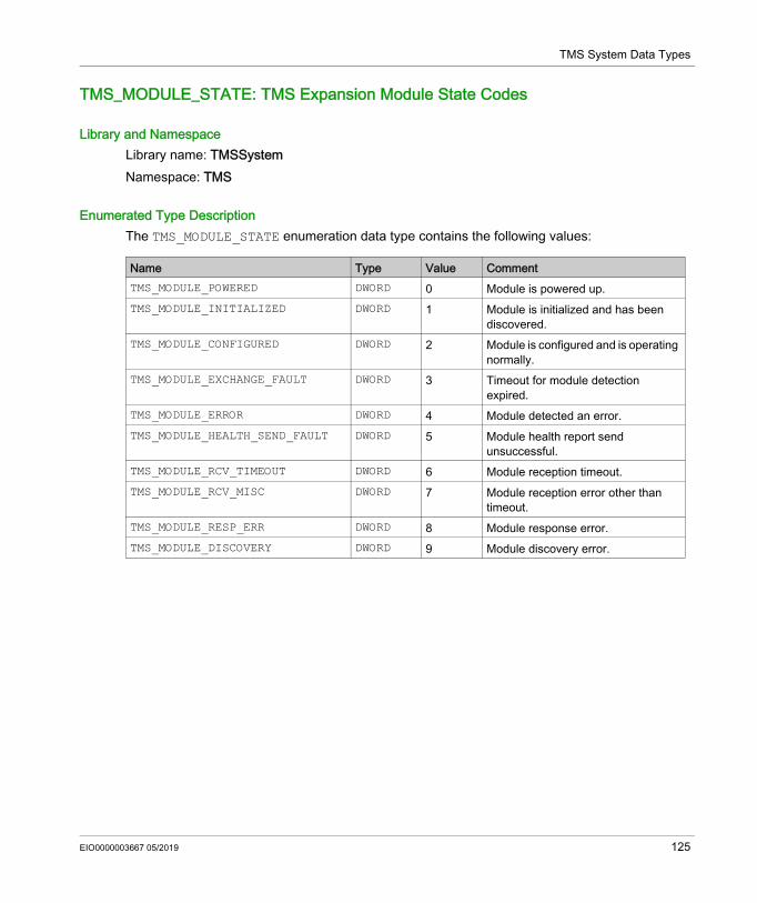
TMS System Data Types
TMS_MODULE_STATE: TMS Expansion Module State Codes
Library and NamespaceLibrary name: TMSSystemNamespace: TMS
Enumerated Type DescriptionThe TMS_MODULE_STATE enumeration data type contains the following values:
Name Type Value CommentTMS_MODULE_POWERED DWORD 0 Module is powered up.TMS_MODULE_INITIALIZED DWORD 1 Module is initialized and has been
discovered.TMS_MODULE_CONFIGURED DWORD 2 Module is configured and is operating
normally.TMS_MODULE_EXCHANGE_FAULT DWORD 3 Timeout for module detection
expired.TMS_MODULE_ERROR DWORD 4 Module detected an error.TMS_MODULE_HEALTH_SEND_FAULT DWORD 5 Module health report send
unsuccessful.TMS_MODULE_RCV_TIMEOUT DWORD 6 Module reception timeout.TMS_MODULE_RCV_MISC DWORD 7 Module reception error other than
timeout.TMS_MODULE_RESP_ERR DWORD 8 Module response error.TMS_MODULE_DISCOVERY DWORD 9 Module discovery error.
EIO0000003667 05/2019 125
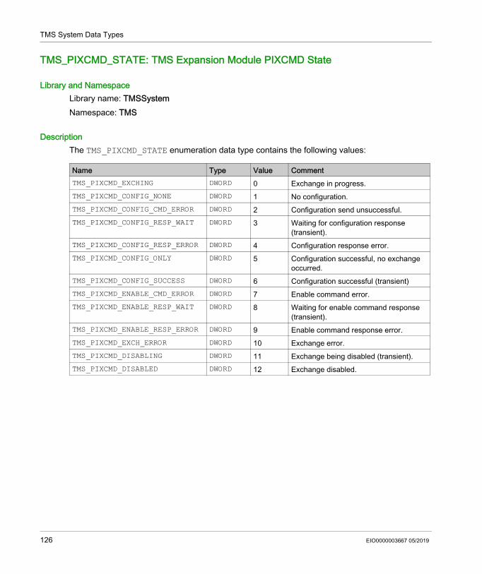
TMS System Data Types
TMS_PIXCMD_STATE: TMS Expansion Module PIXCMD State
Library and NamespaceLibrary name: TMSSystemNamespace: TMS
DescriptionThe TMS_PIXCMD_STATE enumeration data type contains the following values:
Name Type Value CommentTMS_PIXCMD_EXCHING DWORD 0 Exchange in progress.TMS_PIXCMD_CONFIG_NONE DWORD 1 No configuration.TMS_PIXCMD_CONFIG_CMD_ERROR DWORD 2 Configuration send unsuccessful.TMS_PIXCMD_CONFIG_RESP_WAIT DWORD 3 Waiting for configuration response
(transient).TMS_PIXCMD_CONFIG_RESP_ERROR DWORD 4 Configuration response error.TMS_PIXCMD_CONFIG_ONLY DWORD 5 Configuration successful, no exchange
occurred.TMS_PIXCMD_CONFIG_SUCCESS DWORD 6 Configuration successful (transient)TMS_PIXCMD_ENABLE_CMD_ERROR DWORD 7 Enable command error.TMS_PIXCMD_ENABLE_RESP_WAIT DWORD 8 Waiting for enable command response
(transient).TMS_PIXCMD_ENABLE_RESP_ERROR DWORD 9 Enable command response error.TMS_PIXCMD_EXCH_ERROR DWORD 10 Exchange error.TMS_PIXCMD_DISABLING DWORD 11 Exchange being disabled (transient).TMS_PIXCMD_DISABLED DWORD 12 Exchange disabled.
126 EIO0000003667 05/2019
Modicon M262 Logic/Motion Controller
EIO0000003667 05/2019
Appendices
EIO0000003667 05/2019 127

128 EIO0000003667 05/2019
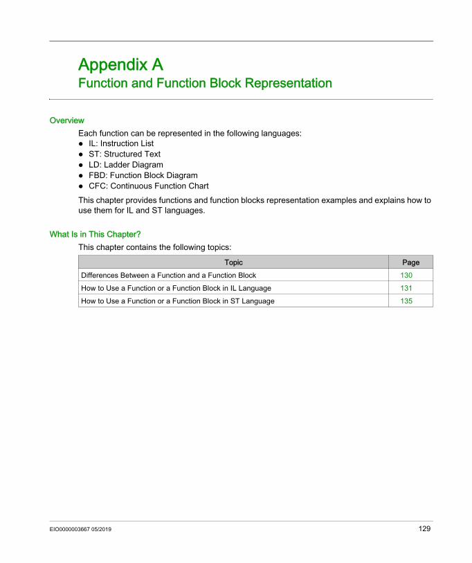
Modicon M262 Logic/Motion ControllerFunction and Function Block RepresentationEIO0000003667 05/2019
Function and Function Block Representation
Appendix AFunction and Function Block Representation
OverviewEach function can be represented in the following languages: IL: Instruction List ST: Structured Text LD: Ladder Diagram FBD: Function Block Diagram CFC: Continuous Function ChartThis chapter provides functions and function blocks representation examples and explains how to use them for IL and ST languages.
What Is in This Chapter?This chapter contains the following topics:
Topic PageDifferences Between a Function and a Function Block 130How to Use a Function or a Function Block in IL Language 131How to Use a Function or a Function Block in ST Language 135
EIO0000003667 05/2019 129
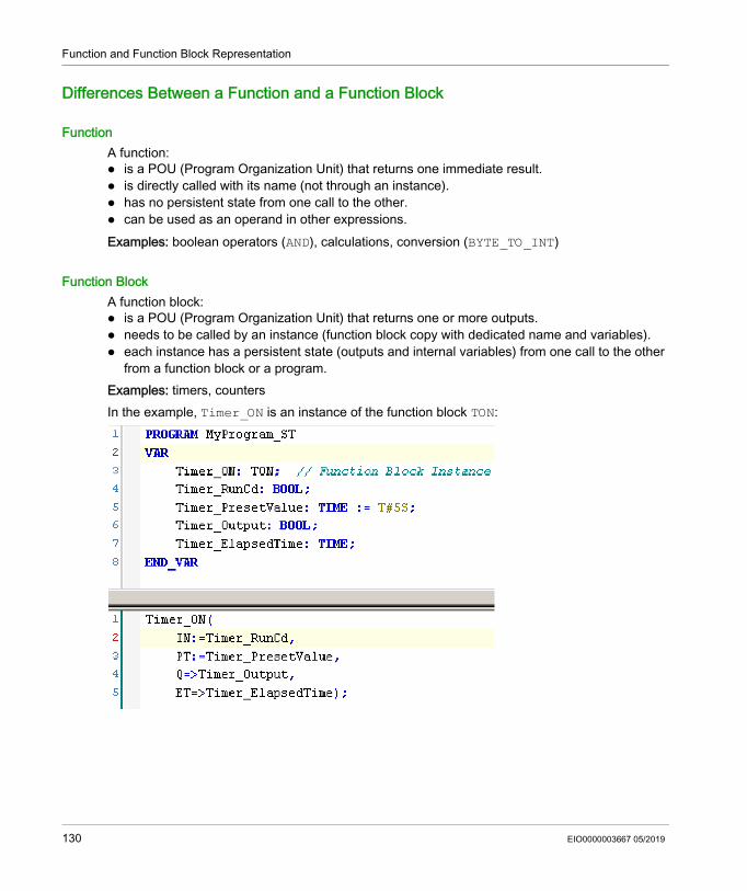
Function and Function Block Representation
Differences Between a Function and a Function Block
FunctionA function: is a POU (Program Organization Unit) that returns one immediate result. is directly called with its name (not through an instance). has no persistent state from one call to the other. can be used as an operand in other expressions.Examples: boolean operators (AND), calculations, conversion (BYTE_TO_INT)
Function BlockA function block: is a POU (Program Organization Unit) that returns one or more outputs. needs to be called by an instance (function block copy with dedicated name and variables). each instance has a persistent state (outputs and internal variables) from one call to the other
from a function block or a program.Examples: timers, countersIn the example, Timer_ON is an instance of the function block TON:
130 EIO0000003667 05/2019
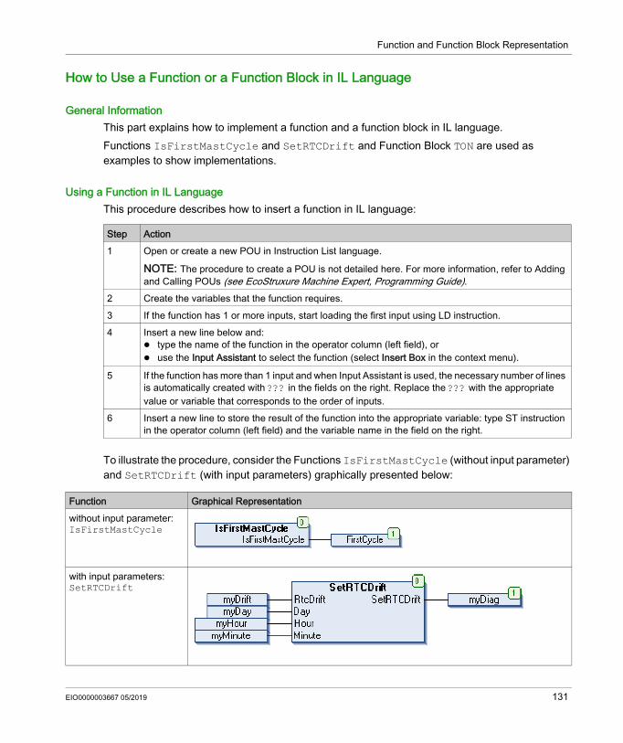
Function and Function Block Representation
How to Use a Function or a Function Block in IL Language
General InformationThis part explains how to implement a function and a function block in IL language.Functions IsFirstMastCycle and SetRTCDrift and Function Block TON are used as examples to show implementations.
Using a Function in IL LanguageThis procedure describes how to insert a function in IL language:
To illustrate the procedure, consider the Functions IsFirstMastCycle (without input parameter) and SetRTCDrift (with input parameters) graphically presented below:
Step Action1 Open or create a new POU in Instruction List language.
NOTE: The procedure to create a POU is not detailed here. For more information, refer to Adding and Calling POUs (see EcoStruxure Machine Expert, Programming Guide).
2 Create the variables that the function requires.3 If the function has 1 or more inputs, start loading the first input using LD instruction.4 Insert a new line below and:
type the name of the function in the operator column (left field), or use the Input Assistant to select the function (select Insert Box in the context menu).
5 If the function has more than 1 input and when Input Assistant is used, the necessary number of lines is automatically created with ??? in the fields on the right. Replace the ??? with the appropriate value or variable that corresponds to the order of inputs.
6 Insert a new line to store the result of the function into the appropriate variable: type ST instruction in the operator column (left field) and the variable name in the field on the right.
Function Graphical Representationwithout input parameter:IsFirstMastCycle
with input parameters:SetRTCDrift
EIO0000003667 05/2019 131
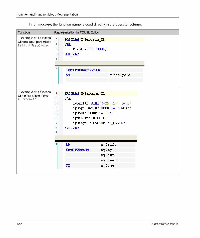
Function and Function Block Representation
In IL language, the function name is used directly in the operator column:
Function Representation in POU IL EditorIL example of a function without input parameter:IsFirstMastCycle
IL example of a function with input parameters:SetRTCDrift
132 EIO0000003667 05/2019
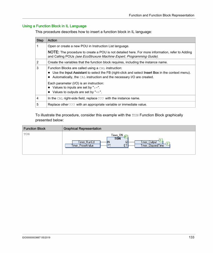
Function and Function Block Representation
Using a Function Block in IL LanguageThis procedure describes how to insert a function block in IL language:
To illustrate the procedure, consider this example with the TON Function Block graphically presented below:
Step Action1 Open or create a new POU in Instruction List language.
NOTE: The procedure to create a POU is not detailed here. For more information, refer to Adding and Calling POUs (see EcoStruxure Machine Expert, Programming Guide).
2 Create the variables that the function block requires, including the instance name.3 Function Blocks are called using a CAL instruction:
Use the Input Assistant to select the FB (right-click and select Insert Box in the context menu). Automatically, the CAL instruction and the necessary I/O are created.
Each parameter (I/O) is an instruction: Values to inputs are set by ":=". Values to outputs are set by "=>".
4 In the CAL right-side field, replace ??? with the instance name.
5 Replace other ??? with an appropriate variable or immediate value.
Function Block Graphical RepresentationTON
EIO0000003667 05/2019 133
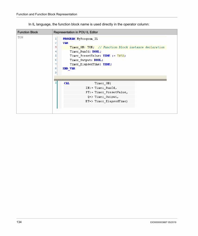
Function and Function Block Representation
In IL language, the function block name is used directly in the operator column:
Function Block Representation in POU IL EditorTON
134 EIO0000003667 05/2019
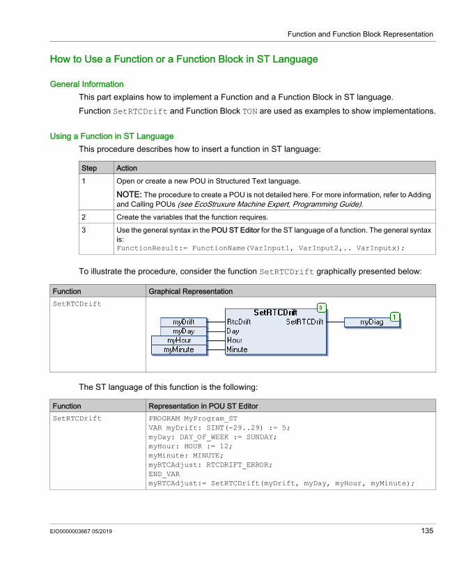
Function and Function Block Representation
How to Use a Function or a Function Block in ST Language
General InformationThis part explains how to implement a Function and a Function Block in ST language.Function SetRTCDrift and Function Block TON are used as examples to show implementations.
Using a Function in ST LanguageThis procedure describes how to insert a function in ST language:
To illustrate the procedure, consider the function SetRTCDrift graphically presented below:
The ST language of this function is the following:
Step Action1 Open or create a new POU in Structured Text language.
NOTE: The procedure to create a POU is not detailed here. For more information, refer to Adding and Calling POUs (see EcoStruxure Machine Expert, Programming Guide).
2 Create the variables that the function requires.3 Use the general syntax in the POU ST Editor for the ST language of a function. The general syntax
is:FunctionResult:= FunctionName(VarInput1, VarInput2,.. VarInputx);
Function Graphical RepresentationSetRTCDrift
Function Representation in POU ST EditorSetRTCDrift PROGRAM MyProgram_ST
VAR myDrift: SINT(-29..29) := 5;myDay: DAY_OF_WEEK := SUNDAY;myHour: HOUR := 12;myMinute: MINUTE;myRTCAdjust: RTCDRIFT_ERROR;END_VARmyRTCAdjust:= SetRTCDrift(myDrift, myDay, myHour, myMinute);
EIO0000003667 05/2019 135
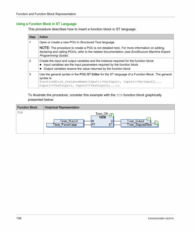
Function and Function Block Representation
Using a Function Block in ST LanguageThis procedure describes how to insert a function block in ST language:
To illustrate the procedure, consider this example with the TON function block graphically presented below:
Step Action1 Open or create a new POU in Structured Text language.
NOTE: The procedure to create a POU is not detailed here. For more information on adding, declaring and calling POUs, refer to the related documentation (see EcoStruxure Machine Expert, Programming Guide).
2 Create the input and output variables and the instance required for the function block: Input variables are the input parameters required by the function block Output variables receive the value returned by the function block
3 Use the general syntax in the POU ST Editor for the ST language of a Function Block. The general syntax is:FunctionBlock_InstanceName(Input1:=VarInput1, Input2:=VarInput2,... Ouput1=>VarOutput1, Ouput2=>VarOutput2,...);
Function Block Graphical RepresentationTON
136 EIO0000003667 05/2019
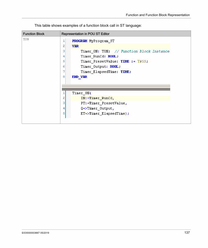
Function and Function Block Representation
This table shows examples of a function block call in ST language:
Function Block Representation in POU ST EditorTON
EIO0000003667 05/2019 137
Function and Function Block Representation
138 EIO0000003667 05/2019
Modicon M262 Logic/Motion ControllerGlossaryEIO0000003667 05/2019
Glossary
Aapplication
A program including configuration data, symbols, and documentation.
ARRAYThe systematic arrangement of data objects of a single type in the form of a table defined in logic controller memory. The syntax is as follows: ARRAY [<dimension>] OF <Type>
Example 1: ARRAY [1..2] OF BOOL is a 1-dimensional table with 2 elements of type BOOL.
Example 2: ARRAY [1..10, 1..20] OF INT is a 2-dimensional table with 10 x 20 elements of type INT.
BBOOL
(boolean) A basic data type in computing. A BOOL variable can have one of these values: 0 (FALSE), 1 (TRUE). A bit that is extracted from a word is of type BOOL; for example, %MW10.4 is a fifth bit of memory word number 10.
Boot application(boot application) The binary file that contains the application. Usually, it is stored in the controller and allows the controller to boot on the application that the user has generated.
BOOTP(bootstrap protocol) A UDP network protocol that can be used by a network client to automatically obtain an IP address (and possibly other data) from a server. The client identifies itself to the server using the client MAC address. The server, which maintains a pre-configured table of client device MAC addresses and associated IP addresses, sends the client its pre-configured IP address. BOOTP was originally used as a method that enabled diskless hosts to be remotely booted over a network. The BOOTP process assigns an infinite lease of an IP address. The BOOTP service utilizes UDP ports 67 and 68.
byteA type that is encoded in an 8-bit format, ranging from 00 hex to FF hex.
EIO0000003667 05/2019 139
Glossary
CCFC
(continuous function chart) A graphical programming language (an extension of the IEC 61131-3 standard) based on the function block diagram language that works like a flowchart. However, no networks are used and free positioning of graphic elements is possible, which allows feedback loops. For each block, the inputs are on the left and the outputs on the right. You can link the block outputs to the inputs of other blocks to create complex expressions.
configurationThe arrangement and interconnection of hardware components within a system and the hardware and software parameters that determine the operating characteristics of the system.
control networkA network containing logic controllers, SCADA systems, PCs, HMI, switches, ... Two kinds of topologies are supported: flat: all modules and devices in this network belong to same subnet. 2 levels: the network is split into an operation network and an inter-controller network.These two networks can be physically independent, but are generally linked by a routing device.
CRC(cyclical redundancy check) A method used to determine the validity of a communication transmission. The transmission contains a bit field that constitutes a checksum. The message is used to calculate the checksum by the transmitter according to the content of the message. Receiving nodes, then recalculate the field in the same manner. Any discrepancy in the value of the 2 CRC calculations indicates that the transmitted message and the received message are different.
DDHCP
(dynamic host configuration protocol) An advanced extension of BOOTP. DHCP is more advanced, but both DHCP and BOOTP are common. (DHCP can handle BOOTP client requests.)
DWORD(double word) Encoded in 32-bit format.
EEthernet
A physical and data link layer technology for LANs, also known as IEEE 802.3.
140 EIO0000003667 05/2019
Glossary
EtherNet/IP(Ethernet industrial protocol) An open communications protocol for manufacturing automation solutions in industrial systems. EtherNet/IP is in a family of networks that implement the common industrial protocol at its upper layers. The supporting organization (ODVA) specifies EtherNet/IP to accomplish global adaptability and media independence.
FFB
(function block) A convenient programming mechanism that consolidates a group of programming instructions to perform a specific and normalized action, such as speed control, interval control, or counting. A function block may comprise configuration data, a set of internal or external operating parameters and usually 1 or more data inputs and outputs.
firmwareRepresents the BIOS, data parameters, and programming instructions that constitute the operating system on a controller. The firmware is stored in non-volatile memory within the controller.
flash memoryA non-volatile memory that can be overwritten. It is stored on a special EEPROM that can be erased and reprogrammed.
functionA programming unit that has 1 input and returns 1 immediate result. However, unlike FBs, it is directly called with its name (as opposed to through an instance), has no persistent state from one call to the next and can be used as an operand in other programming expressions.Examples: boolean (AND) operators, calculations, conversions (BYTE_TO_INT)
function blockA programming unit that has 1 or more inputs and returns 1 or more outputs. FBs are called through an instance (function block copy with dedicated name and variables) and each instance has a persistent state (outputs and internal variables) from 1 call to the other.Examples: timers, counters
function block diagramOne of the 5 languages for logic or control supported by the standard IEC 61131-3 for control systems. Function block diagram is a graphically oriented programming language. It works with a list of networks where each network contains a graphical structure of boxes and connection lines representing either a logical or arithmetic expression, the call of a function block, a jump, or a return instruction.
GGVL
(global variable list) Manages global variables within an EcoStruxure Machine Expert project.
EIO0000003667 05/2019 141
Glossary
Hhex
(hexadecimal)
II/O
(input/output)
ID(identifier/identification)
IEC(international electrotechnical commission) A non-profit and non-governmental international standards organization that prepares and publishes international standards for electrical, electronic, and related technologies.
IEC 61131-3Part 3 of a 3-part IEC standard for industrial automation equipment. IEC 61131-3 is concerned with controller programming languages and defines 2 graphical and 2 textual programming language standards. The graphical programming languages are ladder diagram and function block diagram. The textual programming languages include structured text and instruction list.
IEEE 802.3A collection of IEEE standards defining the physical layer, and the media access control sublayer of the data link layer, of wired Ethernet.
IL(instruction list) A program written in the language that is composed of a series of text-based instructions executed sequentially by the controller. Each instruction includes a line number, an instruction code, and an operand (refer to IEC 61131-3).
INT(integer) A whole number encoded in 16 bits.
IP(Internet protocol Part of the TCP/IP protocol family that tracks the Internet addresses of devices, routes outgoing messages, and recognizes incoming messages.
LLD
(ladder diagram) A graphical representation of the instructions of a controller program with symbols for contacts, coils, and blocks in a series of rungs executed sequentially by a controller (refer to IEC 61131-3).
142 EIO0000003667 05/2019
Glossary
LWORD(long word) A data type encoded in a 64-bit format.
MMAC address
(media access control address) A unique 48-bit number associated with a specific piece of hardware. The MAC address is programmed into each network card or device when it is manufactured.
MASTA processor task that is run through its programming software. The MAST task has 2 sections: IN: Inputs are copied to the IN section before execution of the MAST task. OUT: Outputs are copied to the OUT section after execution of the MAST task.
Nnetwork
A system of interconnected devices that share a common data path and protocol for communications.
PPLC
(programmable logic controller) An industrial computer used to automate manufacturing, industrial, and other electromechanical processes. PLCs are different from common computers in that they are designed to have multiple input and output arrays and adhere to more robust specifications for shock, vibration, temperature, and electrical interference among other things.
POU(program organization unit) A variable declaration in source code and a corresponding instruction set. POUs facilitate the modular re-use of software programs, functions, and function blocks. Once declared, POUs are available to one another.
programThe component of an application that consists of compiled source code capable of being installed in the memory of a logic controller.
protocolA convention or standard definition that controls or enables the connection, communication, and data transfer between 2 computing system and devices.
EIO0000003667 05/2019 143
Glossary
Rrun
A command that causes the controller to scan the application program, read the physical inputs, and write to the physical outputs according to solution of the logic of the program.
SST
(structured text) A language that includes complex statements and nested instructions (such as iteration loops, conditional executions, or functions). ST is compliant with IEC 61131-3.
STOPA command that causes the controller to stop running an application program.
stringA variable that is a series of ASCII characters.
system variableA variable that provides controller data and diagnostic information and allows sending commands to the controller.
Ttask
A group of sections and subroutines, executed cyclically or periodically for the MAST task or periodically for the FAST task.A task possesses a level of priority and is linked to inputs and outputs of the controller. These I/O are refreshed in relation to the task.A controller can have several tasks.
TCP(transmission control protocol) A connection-based transport layer protocol that provides a simultaneous bi-directional transmission of data. TCP is part of the TCP/IP protocol suite.
UUDINT
(unsigned double integer) Encoded in 32 bits.
UINT(unsigned integer) Encoded in 16 bits.
unlocated variableA variable that does not have an address (refer to located variable).
144 EIO0000003667 05/2019
Glossary
Vvariable
A memory unit that is addressed and modified by a program.
Wwatchdog
A watchdog is a special timer used to ensure that programs do not overrun their allocated scan time. The watchdog timer is usually set to a higher value than the scan time and reset to 0 at the end of each scan cycle. If the watchdog timer reaches the preset value, for example, because the program is caught in an endless loop, an error is declared and the program stopped.
WORDA type encoded in a 16-bit format.
EIO0000003667 05/2019 145

Glossary
146 EIO0000003667 05/2019
Modicon M262 Logic/Motion ControllerIndexEIO0000003667 05/2019
Index
Ccycle
GetExternalEventValue, 46IsFirstMastColdCycle, 42IsFirstMastCycle, 43IsFirstMastWarmCycle, 45
DData Types
DataFileCopyError, 71DataFileCopyLocation, 72ETH_R_FRAME_PROTOCOL, 75ETH_R_IP_MODE, 77ETH_R_IPFORWARDING, 76ETH_R_ITF_STRUCT, 78ETH_R_PORT_DUPLEX_STATUS, 80ETH_R_PORT_IP_STATUS, 81ETH_R_PORT_LINK_STATUS, 82ETH_R_PORT_SPEED, 83ETH_R_RUN_IDLE, 84ExecuteScriptError, 73IMMEDIATE_ERR_TYPE, 85PLC_R_APPLICATION_ERROR, 59PLC_R_BOOT_PROJECT_STATUS, 61PLC_R_IO_STATUS, 62PLC_R_SDCARD_STATUS, 63PLC_R_STATUS, 64PLC_R_STOP_CAUSE, 65PLC_R_TERMINAL_PORT_STATUS, 67PLC_R_TM3_BUS_STATE, 68PLC_W_COMMAND, 69TM3_BUS_PARAM_ID, 110TM3_BUS_W_IOBUSERRMOD, 111TM3_BUS_W_IOBUSINIT, 112TM3_ERR_CODE, 114TM3_MODULE_R_ARRAY_TYPE, 115TM3_MODULE_STATE, 116TMS_IP_STATE, 124TMS_MODULE_STATE, 125TMS_PIXCMD_STATE, 126
EIO0000003667 05/2019
DataFileCopycopying data to or from a file, 52
DataFileCopyErrorData Types, 71
DataFileCopyLocationData Types, 72
Eembedded I/O
GetImmediateFastInput, 39PhysicalWriteFastOutputs, 47
ETH_RSystem Variable, 31
ETH_R_FRAME_PROTOCOLData Types, 75
ETH_R_IP_MODEData Types, 77
ETH_R_IPFORWARDINGData Types, 76
ETH_R_ITF_STRUCTData Types, 78
ETH_R_PORT_DUPLEX_STATUSData Types, 80
ETH_R_PORT_LINK_STATUSData Types, 82
ETH_R_PORT_SPEEDData Types, 83
ETH_WSystem Variable, 36
ExecuteScriptrunning script commands, 55
ExecuteScriptErrorData Types, 73
FFB_CheckAllowedControllerMacAddress
function blocks, 50FB_ControlClone
function block, 51
147
Index
file copy commandsDataFileCopy, 52
function blocksFB_CheckAllowedControllerMacAd-dress, 50
functionsdifferences between a function and a function block, 130how to use a function or a function block in IL language, 131how to use a function or a function block in ST language, 135
GGetExternalEventValue
get current value of an external event, 46GetImmediateFastInput
getting the value of a fast input, 39GetRtc
getting real time clock (RTC) value, 41
IIMMEDIATE_ERR_TYPE
Data Types, 85IsFirstMastColdCycle
first cold start cycle, 42IsFirstMastCycle
first mast cycle, 43IsFirstMastWarmCycle
first warm start cycle, 45
148
MM241 PLCSystem
DataFileCopy, 52ExecuteScript, 55GetImmediateFastInput, 39GetRtc, 41IsFirstMastColdCycle, 42IsFirstMastCycle, 43IsFirstMastWarmCycle, 45PhysicalWriteFastOutputs, 47TM3_GetModuleBusStatus, 103, 104TM3_SendDc2Cmd, 106
M262 PLCSystemGetExternalEventValue, 46storetm3bus_w, 102syslog_control, 89
PPhysicalWriteFastOutputs
writing output of an embedded expert I/O, 47
PLC_RSystem Variable, 24
PLC_R_APPLICATION_ERRORData Types, 59
PLC_R_BOOT_PROJECT_STATUSData Types, 61
PLC_R_IO_STATUSData Types, 62
PLC_R_SDCARD_STATUSData Types, 63
PLC_R_STATUSData Types, 64
PLC_R_STOP_CAUSEData Types, 65
PLC_R_TERMINAL_PORT_STATUSData Types, 67
PLC_R_TM3_BUS_STATEData Types, 68
PLC_WSystem Variable, 29
PLC_W_COMMANDData Types, 69
EIO0000003667 05/2019
Index
Rreal time clock
GetRtc, 41RTC
GetRtc, 41
Sscript commands
ExecuteScript, 55SERIAL_R_STRUCT
System Variable, 94SERIAL_W_STRUCT
System Variable, 95storetm3bus_w
getting the bus status of a TM3 module, 102
STRUCT_TMS_BUS_DIAGsystem variables, 120
STRUCT_TMS_MODULE_DIAGsystem variables, 121
syslog_control, 89System Variable
ETH_R, 31ETH_W, 36PLC_R, 24PLC_W, 29SERIAL_R_STRUCT, 94SERIAL_W_STRUCT, 95TM3_BUS_W, 113TM3_MODULE_R, 99
System VariablesDefinition, 19
system variablesSTRUCT_TMS_BUS_DIAG, 120STRUCT_TMS_MODULE_DIAG, 121
System VariablesUsing, 21
TTM3
storetm3bus_w, 102TM3 module bus status
TM3_GetModuleBusStatus, 103
EIO0000003667 05/2019
TM3 module internal statusTM3_GetModuleInternalStatus, 104
TM3 SendDc2CmdTM3_SendDc2Cmd, 106
TM3_BUS_PARAM_IDData Types, 110
TM3_BUS_Wsystem variable, 113
TM3_BUS_W_IOBUSERRMODData Types, 111
TM3_BUS_W_IOBUSINITData Types, 112
TM3_ERR_CODEData Types, 114
TM3_GetModuleBusStatusgetting the bus status of a TM3 module, 103
TM3_GetModuleInternalStatusgetting the internal status of a TM3 mod-ule, 104
TM3_MODULE_RSystem Variable, 99
TM3_MODULE_R_ARRAY_TYPEData Types, 115
TM3_MODULE_STATEData Types, 116
TM3_SendDc2Cmdgetting the bus status of a TM3 module, 106
TMS_IP_STATEData Types, 124
TMS_MODULE_STATEData Types, 125
TMS_PIXCMD_STATEData Types, 126
Uunction blocks
FB_ControlClone, 51
149

Index
150
EIO0000003667 05/2019