Embed Size (px)
DESCRIPTION
Modular Puddle Duck Racer Plans
Citation preview
MARCH 2011
Main Hull26"Max.
48"
FRONT VIEW
Main Hull
Nested Modules
SIDE VIEW
54"
- NESTED VIEWS -
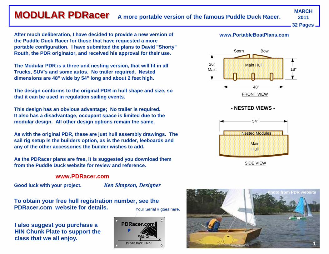
A more portable version of the famous Puddle Duck R acer.
After much deliberation, I have decided to provide a new version of the Puddle Duck Racer for those that have requested a more portable configuration. I have submitted the plans to David "Shorty" Routh, the PDR originator, and received his approva l for their use.
The Modular PDR is a three unit nesting version, th at will fit in all Trucks, SUV's and some autos. No trailer required. Nested dimensions are 48" wide by 54" long and about 2 fee t high.
The design conforms to the original PDR in hull sha pe and size, so that it can be used in regulation sailing events.
This design has an obvious advantage; No trailer i s required.It also has a disadvantage, occupant space is limit ed due to the modular design. All other design options remain th e same.
As with the original PDR, these are just hull assem bly drawings. The sail rig setup is the builders option, as is the ru dder, leeboards and any of the other accessories the builder wishes to add.
As the PDRacer plans are free, it is suggested you download them from the Puddle Duck website for review and referen ce.
www.PDRacer.com
Good luck with your project. Ken Simpson, Designer
To obtain your free hull registration number, see t he PDRacer.com website for details.
18"
1
Photo from PDR website
Stern Bow
www.PortableBoatPlans.com
I also suggest you purchase a HIN Chunk Plate to support the class that we all enjoy.
32 Pages
MODULAR PDRacerMODULAR PDRacer
Your Serial # goes here.
2
General NotesThe design of a Nesting PDR is a direct response to many requests by PortableBoatPlans.com viewers.
The drawings have been reviewed, and approved, by D avid "Shorty" Routh. the PDR originator.It includes the standard beam, freeboard, air cells , and construction methods.
It is lightweight, sturdy, easy to build, very port able and utilizes the standard sail platform.
The hull is strong and yet lightweight, and uses tr aditional methods of panel assembly , This provides for a durable, yet truly portable fin ished boat, and the building process is easily
mastered by the home handyman and amateur boat buil der. As a result, only hand tools, a jig-saw, a power dr ill and a large carpenters square
is all that will be required throughout the assemb ly process.
Be selective in your choice of materials. Use plyw ood that is preferably exterior rated.Marine or Luan Plywood may not be available, so the use of 1/4” ACX grade is suggested, but be choosy .
It is important to note, the final choice of materi als is the sole decision of the builder.We have made specific building recommendations, but if the builder has previous experience
with different methods and materials, that is their choice, and we respect that decision.
Certainly, minor changes in design are encouraged, to provide a 'custom' boat to satisfy a builders specific needs. We do not make changes to the drawings.
This would be up to the individual builder, and the ir responsibility. Also, it is very important that none of the basic design parameters be drastically modified,
as this may adversely affect overall boat safety or performance.Seating choice is also up to the builder.
It should also be noted that the hull modules can b e glued and screwed together, for those that do not have limitations of storage or transportation.
The hull exterior can also be completely fiberglass ed for durability, allowing yet thinner and lighter (4 or 5 mm) plywood hull buildi ng material .
Any questions or comments regarding the constructio n and/or design of this project will be responded t o in a timely fashion. Thank you foryour interest and purchasing these pla ns, and good luck with your project.
And don’t forget to visit www.PortableBoatPlans.Com for new designs and updates.Happy Boating !
Ken Simpson , Designer
This is an experimental design drawn up by an untrained amateur. The Designer accpets no liability for any loss or damage sustained during construction or use. Builders may use these plans to construct small numbers of boats freely for their own use. Commercial manufacturers must ask the designer to negotiate perm ission.
3
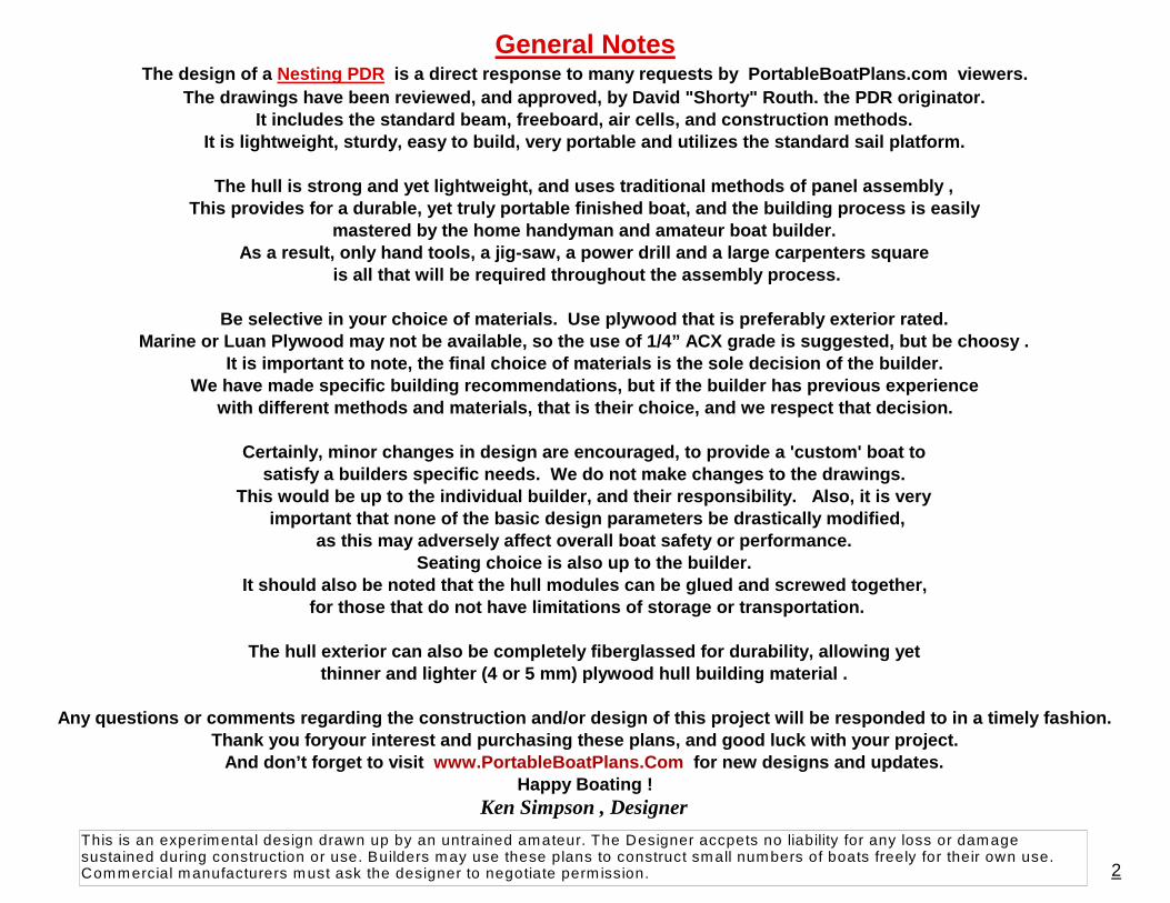
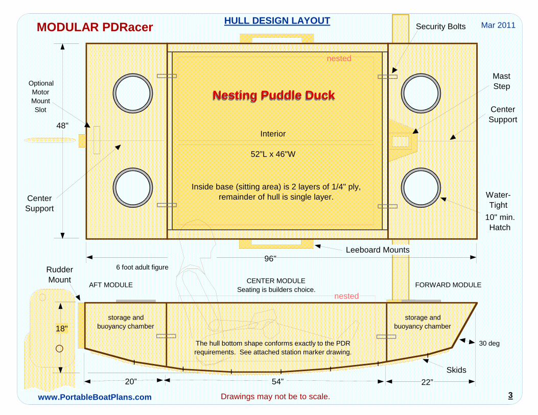
HULL DESIGN LAYOUT
54”20” 22”
storage and buoyancy chamber
storage andbuoyancy chamber
Interior
52”L x 46"W
Nesting Puddle Duck Nesting Puddle Duck
96"
MastStep
10" min.Hatch
OptionalMotorMountSlot
CenterSupport
Security Bolts
CenterSupport
Inside base (sitting area) is 2 layers of 1/4" ply, remainder of hull is single layer.
Seating is builders choice.
RudderMount
The hull bottom shape conforms exactly to the PDR requirements. See attached station marker drawing.
6 foot adult figure
Skids
AFT MODULE FORWARD MODULECENTER MODULE
MODULAR PDRacer
Leeboard Mounts
nested
Water-Tight
Drawings may not be to scale.
nested
30 deg
Mar 2011
48"
www.PortableBoatPlans.com
18"
4
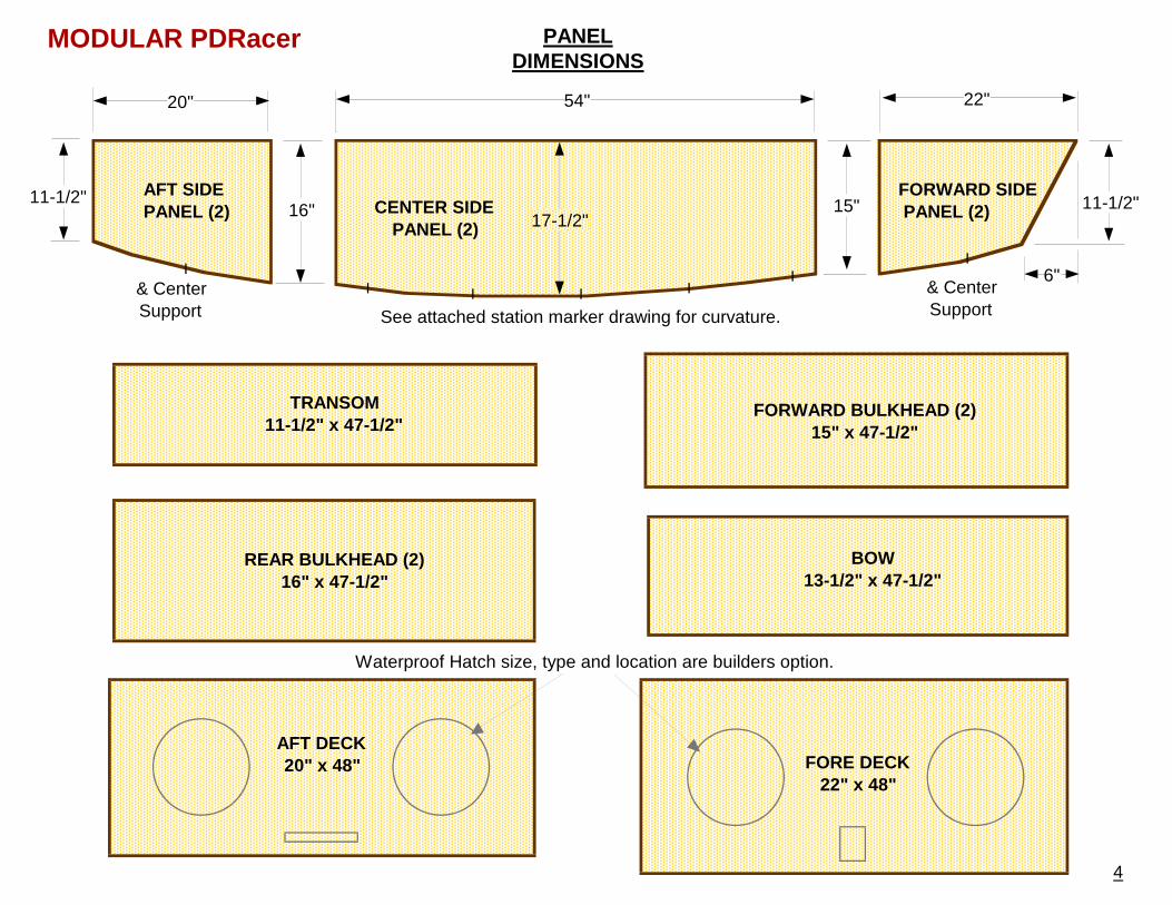
PANELDIMENSIONS
TRANSOM11-1/2" x 47-1/2"
REAR BULKHEAD (2)16" x 47-1/2"
FORWARD BULKHEAD (2)15" x 47-1/2"
BOW13-1/2" x 47-1/2"
AFT DECK20" x 48" FORE DECK
22" x 48"
AFT SIDE PANEL (2)
FORWARD SIDE PANEL (2)CENTER SIDE
PANEL (2)
6"
54"20" 22"
17-1/2"16" 15" 11-1/2"11-1/2"
See attached station marker drawing for curvature.
& Center Support
& Center Support
Waterproof Hatch size, type and location are builders option.
MODULAR PDRacer
5
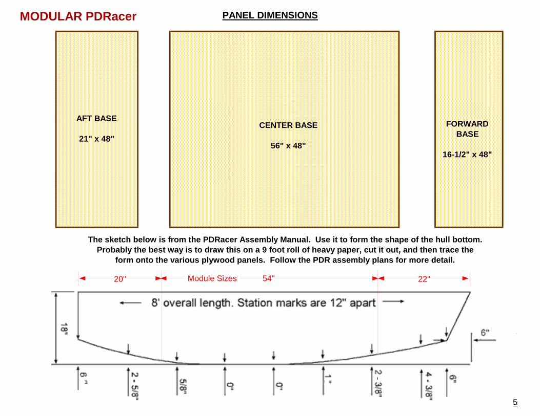
CENTER BASE
56" x 48"
AFT BASE
21" x 48"
FORWARDBASE
16-1/2" x 48"
PANEL DIMENSIONS
The sketch below is from the PDRacer Assembly Manua l. Use it to form the shape of the hull bottom. Probably the best way is to draw this on a 9 foot r oll of heavy paper, cut it out, and then trace the
form onto the various plywood panels. Follow the P DR assembly plans for more detail.
22"20"
MODULAR PDRacer
5
Module Sizes 54"
6
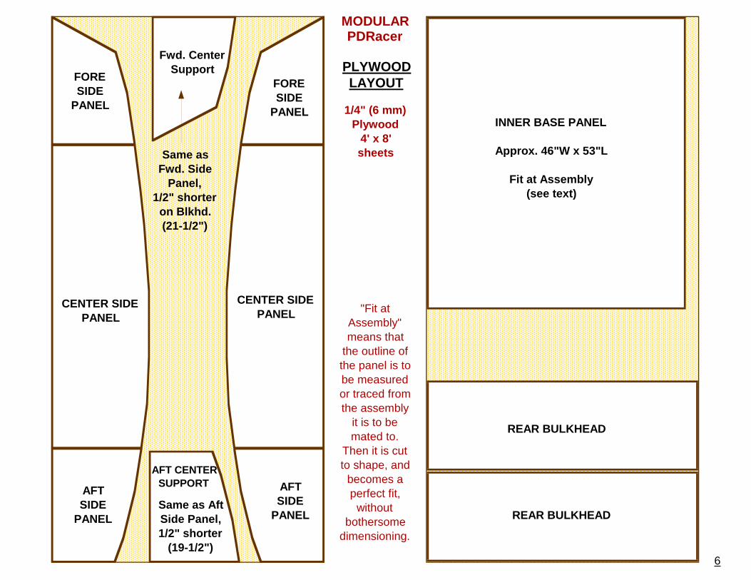
CENTER SIDE PANEL
CENTER SIDE PANEL
PLYWOODLAYOUT
REAR BULKHEAD
REAR BULKHEAD
AFTSIDE
PANEL
AFTSIDE
PANEL
1/4" (6 mm) Plywood
4' x 8'sheets
"Fit at Assembly" means that
the outline of the panel is to be measured or traced from the assembly
it is to be mated to.
Then it is cut to shape, and
becomes a perfect fit,
without bothersome
dimensioning.
Same as Fwd. Side
Panel, 1/2" shorter
on Blkhd. (21-1/2")
AFT CENTERSUPPORT
Same as Aft Side Panel, 1/2" shorter
(19-1/2")
INNER BASE PANEL
Approx. 46"W x 53"L
Fit at Assembly(see text)
MODULARPDRacer
FORESIDE
PANEL
FORESIDE
PANEL
Fwd. Center Support
TRANSOM
1/4" (6 mm) Plywood
4' x 8'sheets
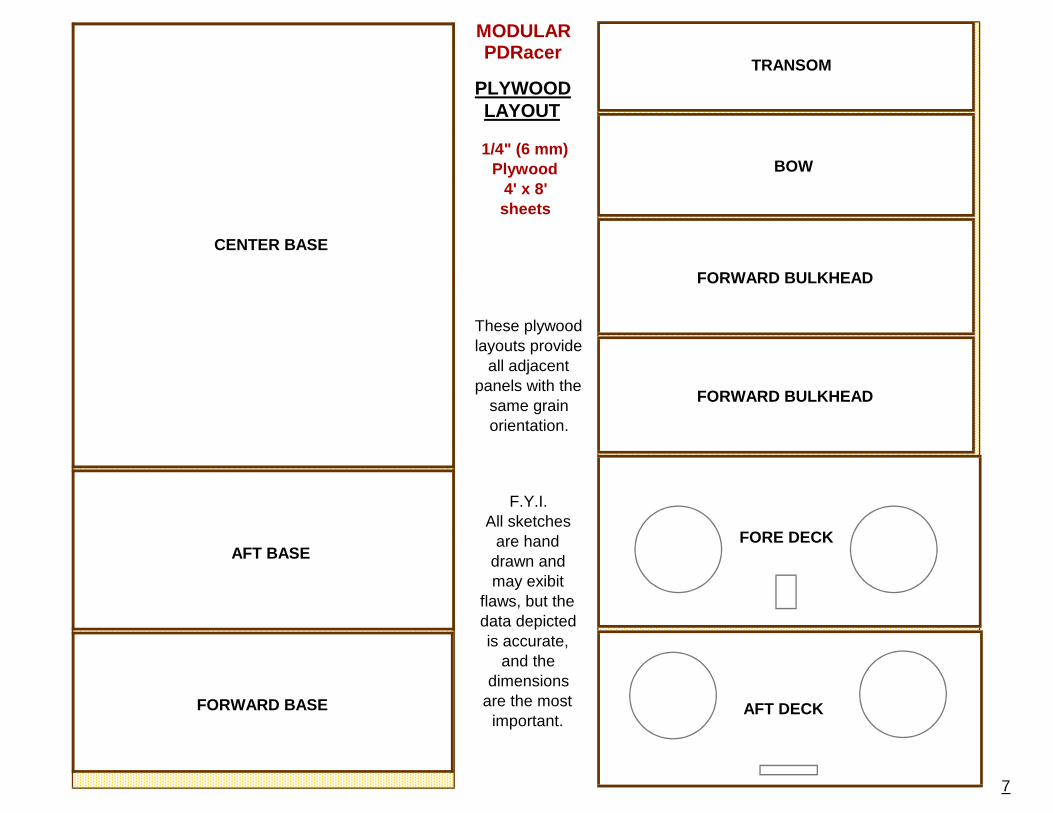
PLYWOODLAYOUT
BOW
FORWARD BULKHEAD
FORWARD BULKHEAD
AFT DECK
FORE DECK
CENTER BASE
AFT BASE
FORWARD BASE
These plywood layouts provide
all adjacent panels with the
same grain orientation.
7
F.Y.I.All sketches
are hand drawn and may exibit
flaws, but the data depicted is accurate,
and the dimensions
are the most important.
MODULARPDRacer
8
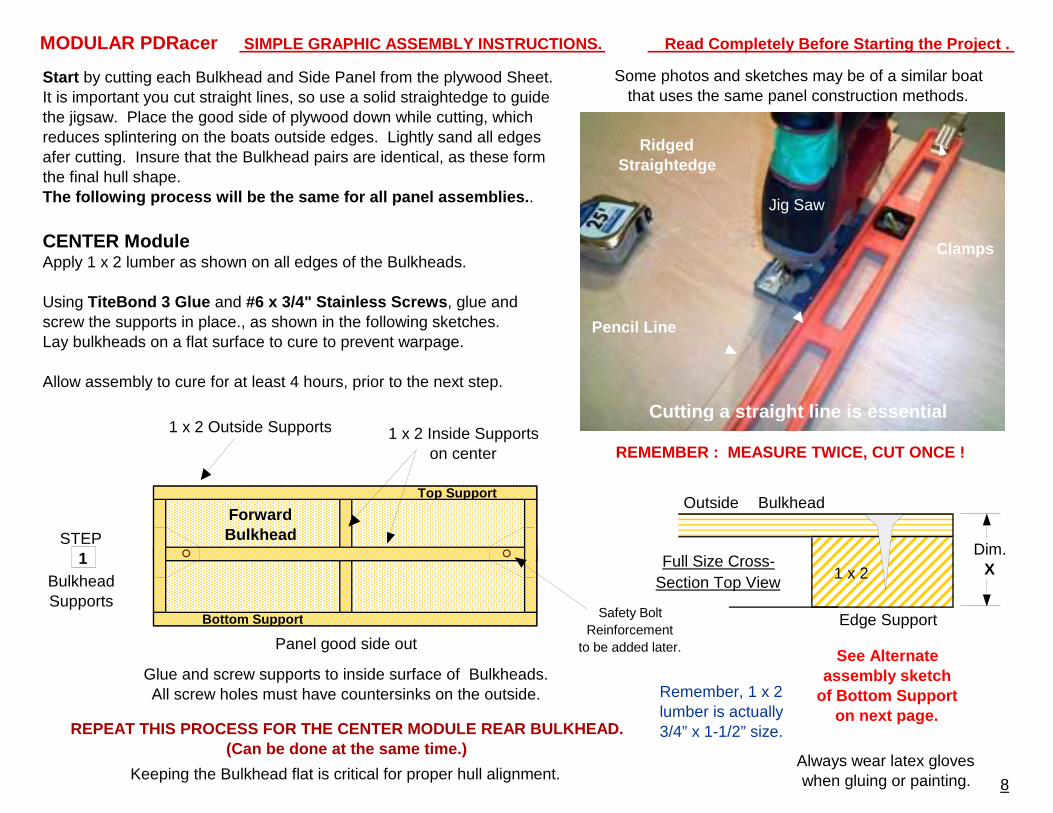
SIMPLE GRAPHIC ASSEMBLY INSTRUCTIONS. Read Completely Before Starting the Project .
Start by cutting each Bulkhead and Side Panel from the plywood Sheet. It is important you cut straight lines, so use a solid straightedge to guide the jigsaw. Place the good side of plywood down while cutting, which reduces splintering on the boats outside edges. Lightly sand all edges afer cutting. Insure that the Bulkhead pairs are identical, as these form the final hull shape.The following process will be the same for all pane l assemblies. .
Some photos and sketches may be of a similar boat that uses the same panel construction methods.
CENTER ModuleApply 1 x 2 lumber as shown on all edges of the Bulkheads.
Using TiteBond 3 Glue and #6 x 3/4" Stainless Screws , glue and screw the supports in place., as shown in the following sketches. Lay bulkheads on a flat surface to cure to prevent warpage.
Allow assembly to cure for at least 4 hours, prior to the next step.
Cutting a straight line is essential
Ridged Straightedge
Pencil Line
Clamps
Jig Saw
REMEMBER : MEASURE TWICE, CUT ONCE !
Always wear latex gloves when gluing or painting.
Glue and screw supports to inside surface of Bulkheads. All screw holes must have countersinks on the outside.
Keeping the Bulkhead flat is critical for proper hull alignment.
Panel good side out
1 STEP
1 x 2 Outside Supports
Outside Bulkhead
Edge Support
BulkheadSupports
1 x 2
Forward Bulkhead
1 x 2 Inside Supportson center
REPEAT THIS PROCESS FOR THE CENTER MODULE REAR BULK HEAD.(Can be done at the same time.)
Dim.XFull Size Cross-
Section Top View
Safety Bolt Reinforcement
to be added later.
MODULAR PDRacer
See Alternate assembly sketch
of Bottom Support on next page.
Remember, 1 x 2 lumber is actually 3/4” x 1-1/2” size.
Bottom Support
Top Support
9
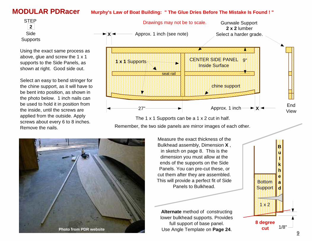
Murphy's Law of Boat Building: " The Glue Dries Be fore The Mistake Is Found ! "
Approx. 1 inch (see note)
CENTER SIDE PANELInside Surface
1 x 1 Supports
27" Approx. 1 inch
The 1 x 1 Supports can be a 1 x 2 cut in half.
2 STEP
SideSupports
Using the exact same process as above, glue and screw the 1 x 1 supports to the Side Panels, as shown at right. Good side out.
Select an easy to bend stringer for the chine support, as it will have to be bent into position, as shown in the photo below. 1 inch nails can be used to hold it in position from the inside, until the screws are applied from the outside. Apply screws about every 6 to 8 inches. Remove the nails.
chine support
Measure the exact thickness of the Bulkhead assembly, Dimension X ,
in sketch on page 8. This is the dimension you must allow at the ends of the supports on the Side Panels. You can pre-cut these, or
cut them after they are assembled.This will provide a perfect fit of Side
Panels to Bulkhead.
X
X2 x 2 lumber
Select a harder grade.
9"
EndView
Gunwale Support
Photo from PDR website
Remember, the two side panels are mirror images of each other.
Drawings may not be to scale.
MODULAR PDRacer
8 degree cut
Alternate method of constructing lower bulkhead supports. Provides
full support of base panel.Use Angle Template on Page 24.
seat rail
Bulkhead
1/8"
BottomSupport
1 x 2
10
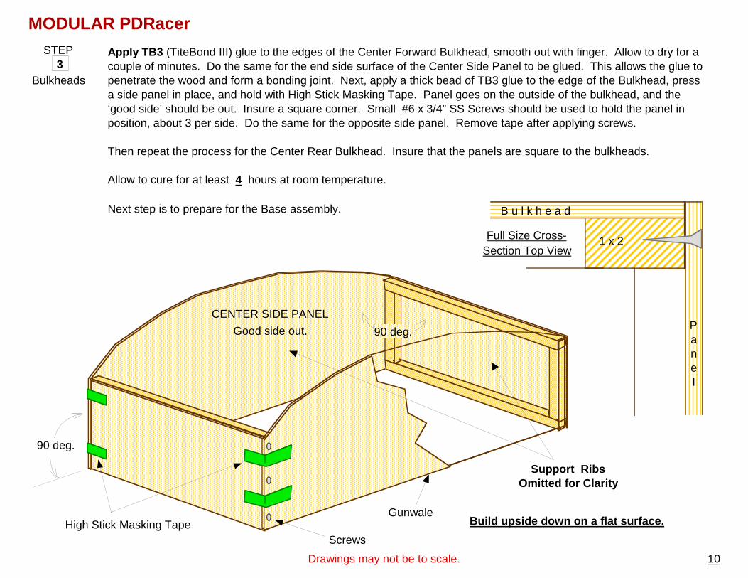
Apply TB3 (TiteBond III) glue to the edges of the Center Forward Bulkhead, smooth out with finger. Allow to dry for a couple of minutes. Do the same for the end side surface of the Center Side Panel to be glued. This allows the glue to penetrate the wood and form a bonding joint. Next, apply a thick bead of TB3 glue to the edge of the Bulkhead, press a side panel in place, and hold with High Stick Masking Tape. Panel goes on the outside of the bulkhead, and the ‘good side’ should be out. Insure a square corner. Small #6 x 3/4” SS Screws should be used to hold the panel in position, about 3 per side. Do the same for the opposite side panel. Remove tape after applying screws. Then repeat the process for the Center Rear Bulkhead. Insure that the panels are square to the bulkheads.
Allow to cure for at least 4 hours at room temperature.
Next step is to prepare for the Base assembly.
3 STEP
Bulkheads
Build upside down on a flat surface.
90 deg.
High Stick Masking Tape
Support Ribs Omitted for Clarity
90 deg.
CENTER SIDE PANEL
Good side out.
Gunwale
B u l k h e a d
Panel
Full Size Cross-Section Top View
Screws
MODULAR PDRacer
Drawings may not be to scale.
1 x 2
11
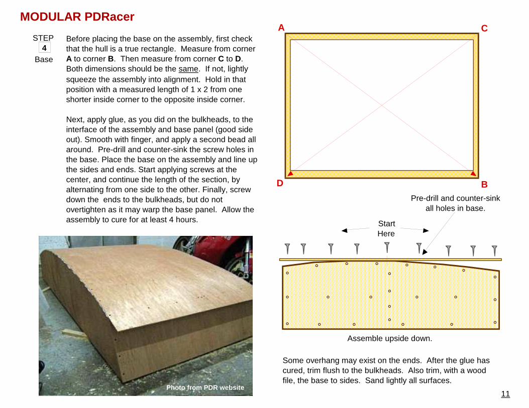
StartHere
A
B
C
D
4 STEP
Base
Before placing the base on the assembly, first check that the hull is a true rectangle. Measure from corner A to corner B. Then measure from corner C to D. Both dimensions should be the same. If not, lightly squeeze the assembly into alignment. Hold in that position with a measured length of 1 x 2 from one shorter inside corner to the opposite inside corner.
Next, apply glue, as you did on the bulkheads, to the interface of the assembly and base panel (good side out). Smooth with finger, and apply a second bead all around. Pre-drill and counter-sink the screw holes in the base. Place the base on the assembly and line up the sides and ends. Start applying screws at the center, and continue the length of the section, by alternating from one side to the other. Finally, screw down the ends to the bulkheads, but do not overtighten as it may warp the base panel. Allow the assembly to cure for at least 4 hours.
Some overhang may exist on the ends. After the glue has cured, trim flush to the bulkheads. Also trim, with a wood file, the base to sides. Sand lightly all surfaces.
Assemble upside down.
Photo from PDR website
MODULAR PDRacer
Pre-drill and counter-sink all holes in base.
12
5 STEP
Skids
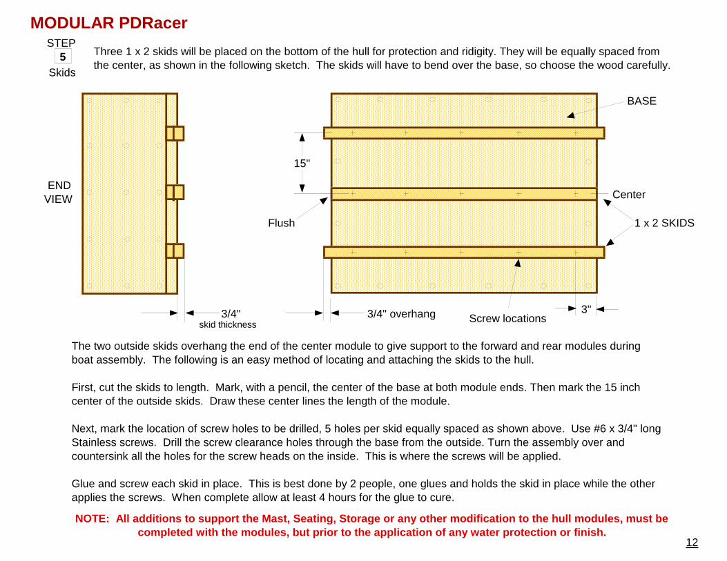
Three 1 x 2 skids will be placed on the bottom of the hull for protection and ridigity. They will be equally spaced from the center, as shown in the following sketch. The skids will have to bend over the base, so choose the wood carefully.
The two outside skids overhang the end of the center module to give support to the forward and rear modules during boat assembly. The following is an easy method of locating and attaching the skids to the hull. First, cut the skids to length. Mark, with a pencil, the center of the base at both module ends. Then mark the 15 inch center of the outside skids. Draw these center lines the length of the module. Next, mark the location of screw holes to be drilled, 5 holes per skid equally spaced as shown above. Use #6 x 3/4" long Stainless screws. Drill the screw clearance holes through the base from the outside. Turn the assembly over and countersink all the holes for the screw heads on the inside. This is where the screws will be applied.
Glue and screw each skid in place. This is best done by 2 people, one glues and holds the skid in place while the other applies the screws. When complete allow at least 4 hours for the glue to cure.
BASE
1 x 2 SKIDS
15"
3/4" overhang
Flush
3/4"skid thickness
Center
Screw locations3"
ENDVIEW
MODULAR PDRacer
NOTE: All additions to support the Mast, Seating, Storage or any other modification to the hull modul es, must be completed with the modules, but prior to the applic ation of any water protection or finish.
13
6 STEP
Inside Floor
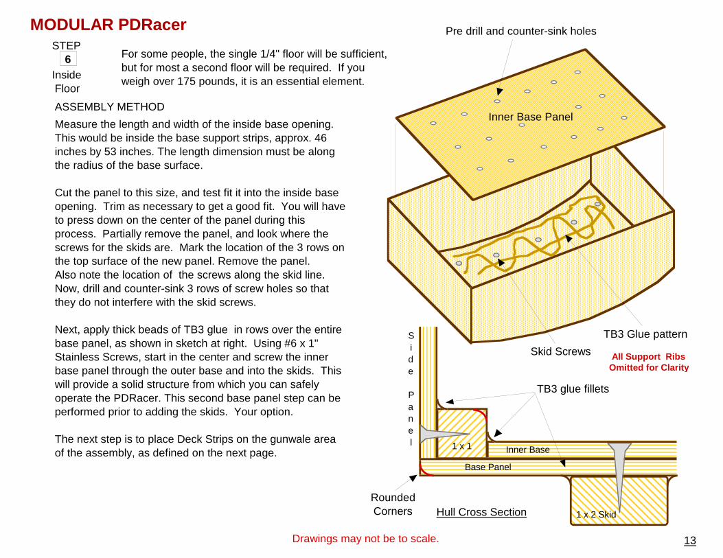
For some people, the single 1/4" floor will be sufficient, but for most a second floor will be required. If you weigh over 175 pounds, it is an essential element.
Measure the length and width of the inside base opening. This would be inside the base support strips, approx. 46 inches by 53 inches. The length dimension must be along the radius of the base surface.
Cut the panel to this size, and test fit it into the inside base opening. Trim as necessary to get a good fit. You will have to press down on the center of the panel during this process. Partially remove the panel, and look where the screws for the skids are. Mark the location of the 3 rows on the top surface of the new panel. Remove the panel.Also note the location of the screws along the skid line. Now, drill and counter-sink 3 rows of screw holes so that they do not interfere with the skid screws. Next, apply thick beads of TB3 glue in rows over the entire base panel, as shown in sketch at right. Using #6 x 1" Stainless Screws, start in the center and screw the inner base panel through the outer base and into the skids. This will provide a solid structure from which you can safely operate the PDRacer. This second base panel step can be performed prior to adding the skids. Your option.
The next step is to place Deck Strips on the gunwale area of the assembly, as defined on the next page.
Inner Base Panel
Pre drill and counter-sink holes
TB3 Glue pattern
Skid Screws
Base Panel
Inner Base
1 x 2 Skid
TB3 glue fillets
ASSEMBLY METHOD
Side
Panel 1 x 1
Drawings may not be to scale.
Hull Cross SectionRounded Corners
MODULAR PDRacer
All Support Ribs Omitted for Clarity
14
MODULAR PDRacer
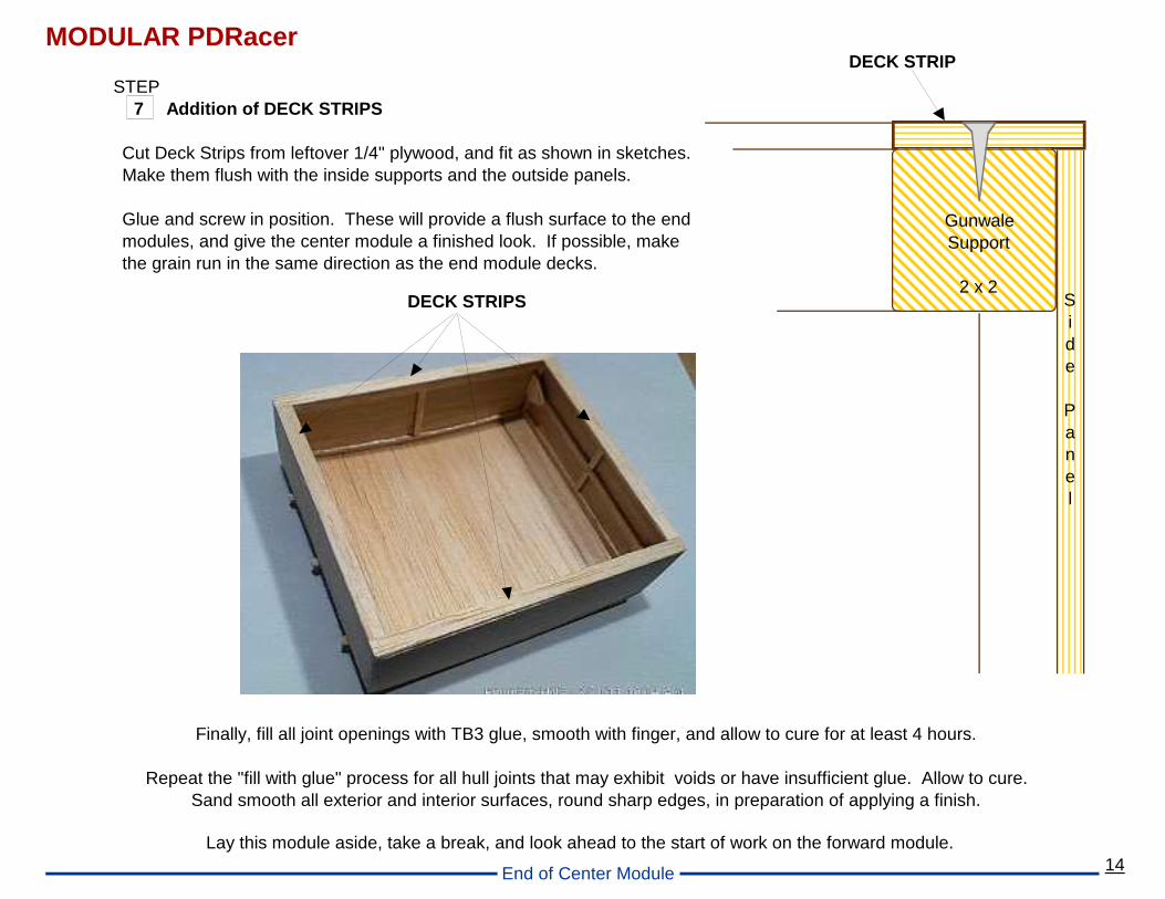
Lay this module aside, take a break, and look ahead to the start of work on the forward module.
Finally, fill all joint openings with TB3 glue, smooth with finger, and allow to cure for at least 4 hours.
Repeat the "fill with glue" process for all hull joints that may exhibit voids or have insufficient glue. Allow to cure.Sand smooth all exterior and interior surfaces, round sharp edges, in preparation of applying a finish.
DECK STRIP
Side
Panel
GunwaleSupport
2 x 2
Cut Deck Strips from leftover 1/4" plywood, and fit as shown in sketches.Make them flush with the inside supports and the outside panels.
Glue and screw in position. These will provide a flush surface to the end modules, and give the center module a finished look. If possible, make the grain run in the same direction as the end module decks.
7 STEP
Addition of DECK STRIPS
DECK STRIPS
End of Center Module
15
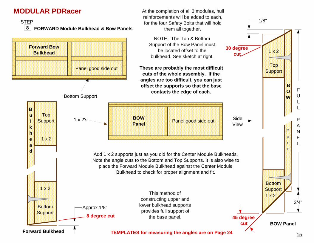
MODULAR PDRacer At the completion of all 3 modules, hull reinforcements will be added to each, for the four Safety Bolts that will hold
them all together.8 STEP
FORWARD Module Bulkhead & Bow Panels
Forward Bow Bulkhead
BottomSupport
8 degree cut
This method of constructing upper and
lower bulkhead supports provides full support of
the base panel.
Bottom Support
Panel
45 degree cut
BottomSupport
BOW Panel
Forward Bulkhead
Add 1 x 2 supports just as you did for the Center Module Bulkheads. Note the angle cuts to the Bottom and Top Supports. It is also wise to
place the Forward Module Bulkhead against the Center Module Bulkhead to check for proper alignment and fit.
3/4"
NOTE: The Top & Bottom Support of the Bow Panel must
be located offset to the bulkhead. See sketch at right.
BOW
TopSupport
BOWPanel
Panel good side out SideView
Bulkhead
TopSupport
30 degree cut
1/8"
TEMPLATES for measuring the angles are on Page 24
Panel good side out
FULL
PANEL
These are probably the most difficult cuts of the whole assembly. If the
angles are too difficult, you can just offset the supports so that the base
contacts the edge of each.
Approx.1/8"
1 x 2's
1 x 2
1 x 2
1 x 2
1 x 2
MODULAR PDRacer
16
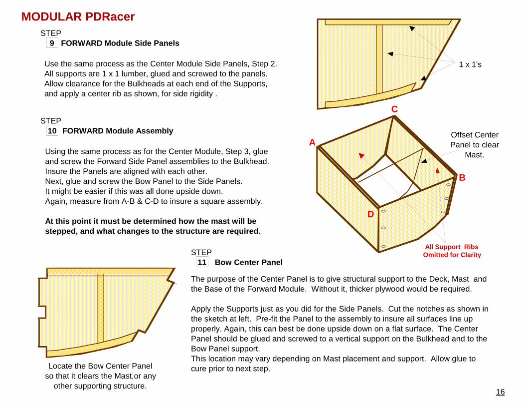
The purpose of the Center Panel is to give structural support to the Deck, Mast and the Base of the Forward Module. Without it, thicker plywood would be required.
Apply the Supports just as you did for the Side Panels. Cut the notches as shown in the sketch at left. Pre-fit the Panel to the assembly to insure all surfaces line up properly. Again, this can best be done upside down on a flat surface. The Center Panel should be glued and screwed to a vertical support on the Bulkhead and to the Bow Panel support. This location may vary depending on Mast placement and support. Allow glue to cure prior to next step.
10 STEP
FORWARD Module Assembly
Using the same process as for the Center Module, Step 3, glue and screw the Forward Side Panel assemblies to the Bulkhead. Insure the Panels are aligned with each other.Next, glue and screw the Bow Panel to the Side Panels. It might be easier if this was all done upside down.Again, measure from A-B & C-D to insure a square assembly.
At this point it must be determined how the mast wi ll be stepped, and what changes to the structure are requ ired.
All Support Ribs Omitted for Clarity
A
B
C
D
9 STEP
FORWARD Module Side Panels
Use the same process as the Center Module Side Panels, Step 2.All supports are 1 x 1 lumber, glued and screwed to the panels.Allow clearance for the Bulkheads at each end of the Supports, and apply a center rib as shown, for side rigidity .
11 STEP
Bow Center Panel
1 x 1's
Locate the Bow Center Panel so that it clears the Mast,or any
other supporting structure.
Offset Center Panel to clear
Mast.
17
MODULAR PDRacer
Good side out.
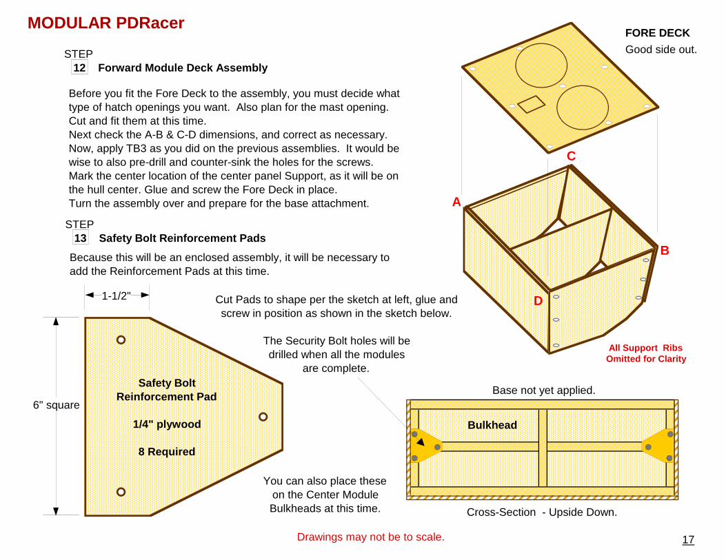
12 STEP
Forward Module Deck Assembly
FORE DECK
Before you fit the Fore Deck to the assembly, you must decide what type of hatch openings you want. Also plan for the mast opening. Cut and fit them at this time. Next check the A-B & C-D dimensions, and correct as necessary. Now, apply TB3 as you did on the previous assemblies. It would be wise to also pre-drill and counter-sink the holes for the screws. Mark the center location of the center panel Support, as it will be on the hull center. Glue and screw the Fore Deck in place. Turn the assembly over and prepare for the base attachment. A
B
C
D
Drawings may not be to scale.
13 STEP
Safety Bolt Reinforcement Pads
6" square
1-1/2"
Safety BoltReinforcement Pad
1/4" plywood
8 Required
Bulkhead
Cross-Section - Upside Down.
Because this will be an enclosed assembly, it will be necessary to add the Reinforcement Pads at this time.
Cut Pads to shape per the sketch at left, glue and screw in position as shown in the sketch below.
The Security Bolt holes will be drilled when all the modules
are complete.
You can also place these on the Center Module Bulkheads at this time.
All Support Ribs Omitted for Clarity
Base not yet applied.
MODULAR PDRacer
18
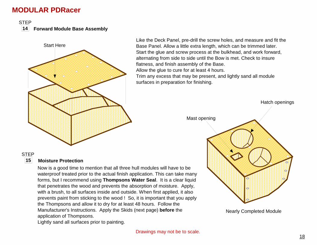
14 STEP
Forward Module Base Assembly
Start HereLike the Deck Panel, pre-drill the screw holes, and measure and fit the Base Panel. Allow a little extra length, which can be trimmed later. Start the glue and screw process at the bulkhead, and work forward, alternating from side to side until the Bow is met. Check to insure flatness, and finish assembly of the Base.Allow the glue to cure for at least 4 hours.Trim any excess that may be present, and lightly sand all module surfaces in preparation for finishing.
15 STEP
Now is a good time to mention that all three hull modules will have to be waterproof treated prior to the actual finish application. This can take many forms, but I recommend using Thompsons Water Seal . It is a clear liquid that penetrates the wood and prevents the absorption of moisture. Apply, with a brush, to all surfaces inside and outside. When first applied, it also prevents paint from sticking to the wood ! So, it is important that you apply the Thompsons and allow it to dry for at least 48 hours. Follow the Manufacturer's Instructions. Apply the Skids (next page) before the application of Thompsons.Lightly sand all surfaces prior to painting.
Moisture Protection
Drawings may not be to scale.
Nearly Completed Module
Hatch openings
Mast opening
19
MODULAR PDRacerSTEP
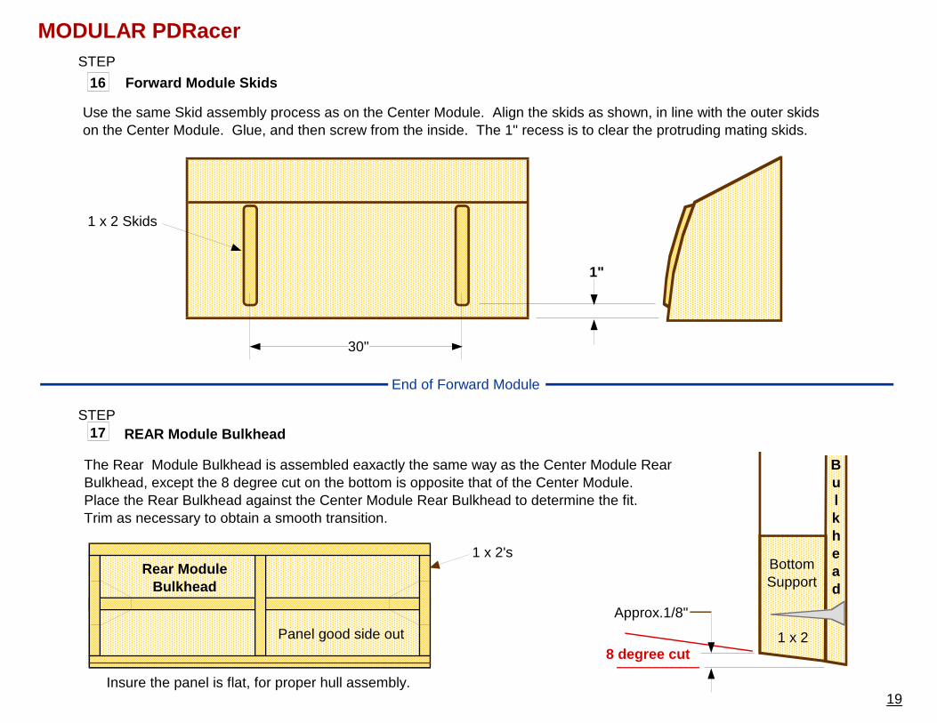
16
1"
30"
Forward Module Skids
Use the same Skid assembly process as on the Center Module. Align the skids as shown, in line with the outer skids on the Center Module. Glue, and then screw from the inside. The 1" recess is to clear the protruding mating skids.
17 STEP
REAR Module Bulkhead
Rear Module Bulkhead
Panel good side out
Bulkhead
BottomSupport
8 degree cut
The Rear Module Bulkhead is assembled eaxactly the same way as the Center Module Rear Bulkhead, except the 8 degree cut on the bottom is opposite that of the Center Module.Place the Rear Bulkhead against the Center Module Rear Bulkhead to determine the fit. Trim as necessary to obtain a smooth transition.
Approx.1/8"
1 x 2's
1 x 2 Skids
1 x 2
Insure the panel is flat, for proper hull assembly.
End of Forward Module
20
MODULAR PDRacer
Transom
BottomSupport
20 degree cut
1/4"
1 x 2
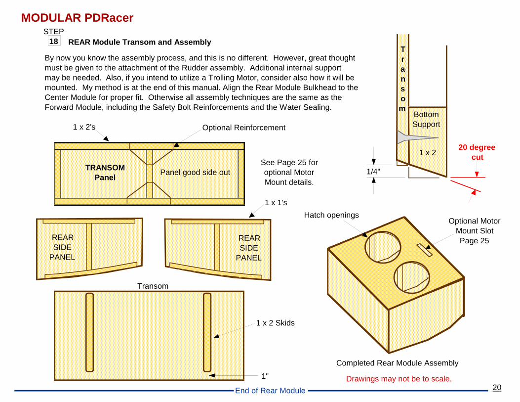
18 STEP
REAR Module Transom and Assembly
Drawings may not be to scale.
1 x 1's
By now you know the assembly process, and this is no different. However, great thought must be given to the attachment of the Rudder assembly. Additional internal support may be needed. Also, if you intend to utilize a Trolling Motor, consider also how it will be mounted. My method is at the end of this manual. Align the Rear Module Bulkhead to the Center Module for proper fit. Otherwise all assembly techniques are the same as the Forward Module, including the Safety Bolt Reinforcements and the Water Sealing.
TRANSOMPanel
Panel good side out
1 x 2's Optional Reinforcement
1 x 2 Skids
Completed Rear Module Assembly
Transom
1"
REARSIDE
PANEL
REARSIDE
PANEL
Hatch openingsOptional Motor
Mount SlotPage 25
See Page 25 for optional Motor Mount details.
End of Rear Module
21
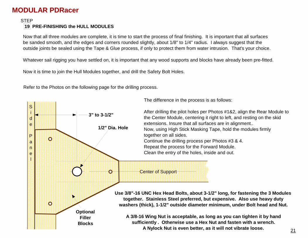
PRE-FINISHING the HULL MODULES19 STEP
Now that all three modules are complete, it is time to start the process of final finishing. It is important that all surfaces be sanded smooth, and the edges and corners rounded slightly, about 1/8" to 1/4" radius. I always suggest that the outside joints be sealed using the Tape & Glue process, if only to protect them from water intrusion. That's your choice.
Whatever sail rigging you have settled on, it is important that any wood supports and blocks have already been pre-fitted.
Now it is time to join the Hull Modules together, and drill the Safety Bolt Holes.
MODULAR PDRacer
3" to 3-1/2"
1/2" Dia. Hole
Side
Panel
Refer to the Photos on the following page for the drilling process.
The difference in the process is as follows:
After drilling the pilot holes per Photos #1&2, align the Rear Module to the Center Module, centering it right to left, and resting on the skid extensions. Insure that all surfaces are in alignment.. Now, using High Stick Masking Tape, hold the modules firmly together on all sides.Continue the drilling process per Photos #3 & 4.Repeat the process for the Forward Module.Clean the entry of the holes, inside and out.
Use 3/8"-16 UNC Hex Head Bolts, about 3-1/2" long, for fastening the 3 Modules together. Stainless Steel preferred, but expensive . Also use heavy duty
washers (thick), 1-1/2" outside diameter minimum, u nder Bolt head and Nut.
A 3/8-16 Wing Nut is acceptable, as long as you can tighten it by hand sufficiently . Otherwise use a Hex Nut and fasten with a wrench.
A Nylock Nut is even better, as it will not vibrate loose.
Center of Support
Optional Filler
Blocks
www.PortableBoatPlans.com
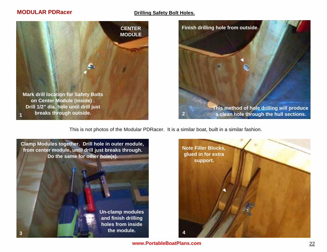
Drilling Safety Bolt Holes.
Clamp Modules together. Drill hole in outer module , from center module, until drill just breaks through .
Do the same for other hole(s).
Un-clamp modules and finish drilling holes from inside
the module.
Finish drilling hole from outside.
This method of hole drilling will produce a clean hole through the hull sections.
Mark drill location for Safety Bolts on Center Module (inside) .
Drill 1/2” dia. hole until drill just breaks through outside.
CENTER MODULE
Note Filler Blocks, glued in for extra
support.
This is not photos of the Modular PDRacer. It is a similar boat, built in a similar fashion.
22
1 2
3 4
MODULAR PDRacer
23
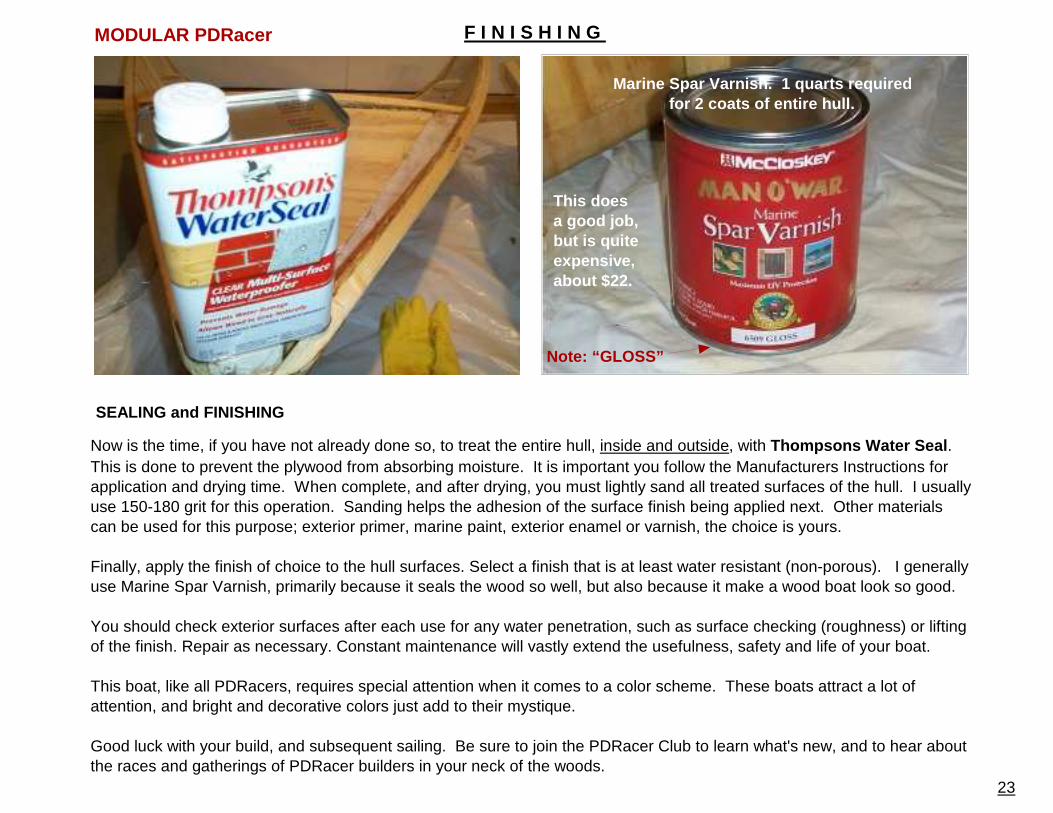
SEALING and FINISHING
Now is the time, if you have not already done so, to treat the entire hull, inside and outside, with Thompsons Water Seal . This is done to prevent the plywood from absorbing moisture. It is important you follow the Manufacturers Instructions for application and drying time. When complete, and after drying, you must lightly sand all treated surfaces of the hull. I usually use 150-180 grit for this operation. Sanding helps the adhesion of the surface finish being applied next. Other materials can be used for this purpose; exterior primer, marine paint, exterior enamel or varnish, the choice is yours.
Finally, apply the finish of choice to the hull surfaces. Select a finish that is at least water resistant (non-porous). I generally use Marine Spar Varnish, primarily because it seals the wood so well, but also because it make a wood boat look so good.
You should check exterior surfaces after each use for any water penetration, such as surface checking (roughness) or lifting of the finish. Repair as necessary. Constant maintenance will vastly extend the usefulness, safety and life of your boat.
This boat, like all PDRacers, requires special attention when it comes to a color scheme. These boats attract a lot of attention, and bright and decorative colors just add to their mystique.
Good luck with your build, and subsequent sailing. Be sure to join the PDRacer Club to learn what's new, and to hear about the races and gatherings of PDRacer builders in your neck of the woods.
Marine Spar Varnish. 1 quarts required for 2 coats of entire hull.
Note: “GLOSS”
This does a good job, but is quite expensive, about $22.
F I N I S H I N G MODULAR PDRacer
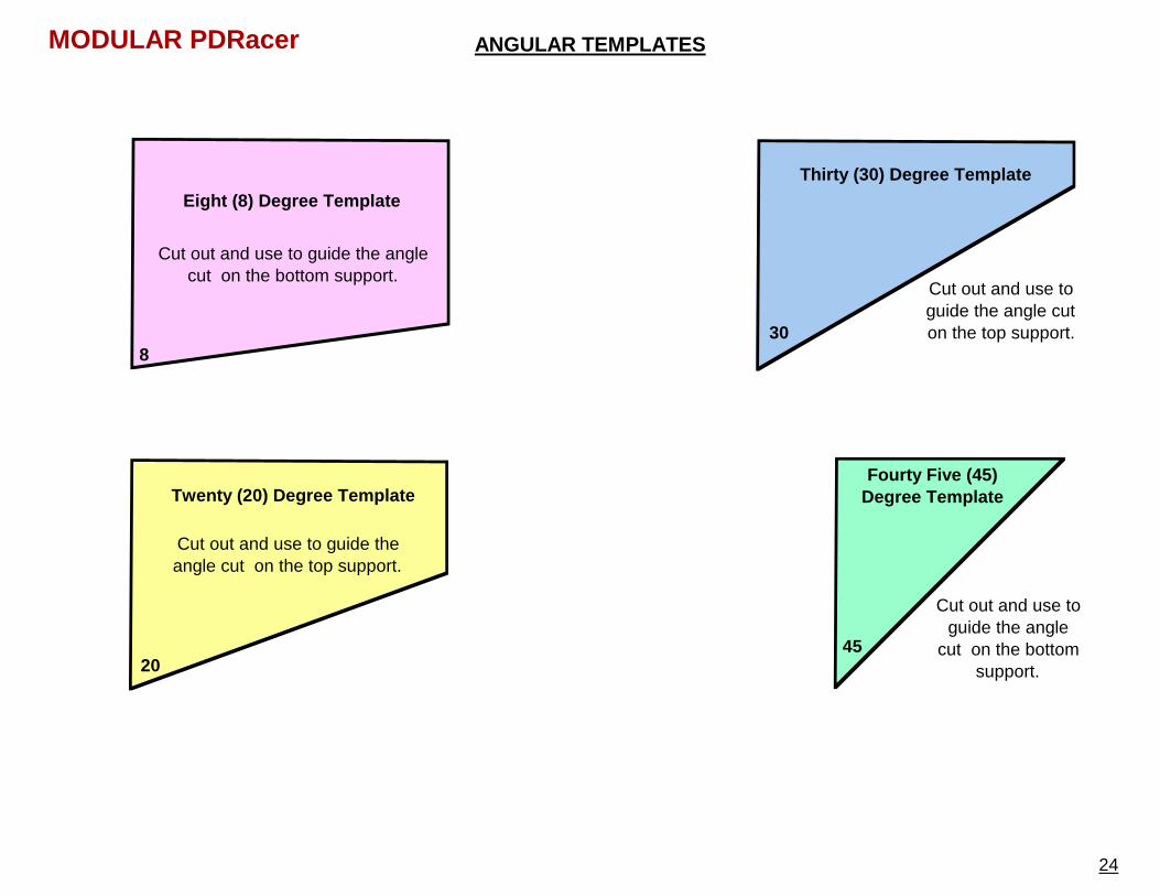
Thirty (30) Degree Template
Cut out and use to guide the angle cut on the top support.30
Eight (8) Degree Template
Cut out and use to guide the angle cut on the bottom support.
8
ANGULAR TEMPLATES
Cut out and use to guide the angle
cut on the bottom support.
Fourty Five (45) Degree Template
4520
Twenty (20) Degree Template
Cut out and use to guide the angle cut on the top support.
24
MODULAR PDRacer
25
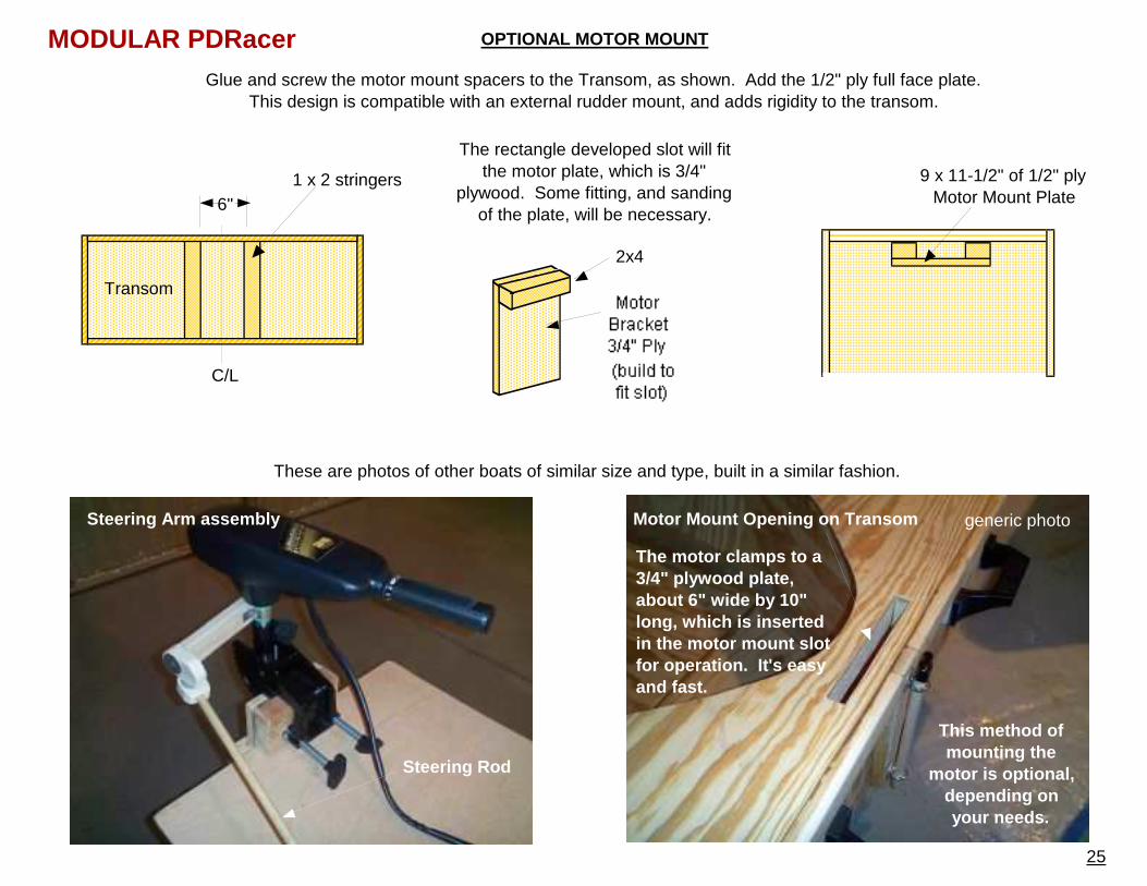
OPTIONAL MOTOR MOUNT
6"1 x 2 stringers 9 x 11-1/2" of 1/2" ply
Motor Mount Plate
Glue and screw the motor mount spacers to the Transom, as shown. Add the 1/2" ply full face plate.This design is compatible with an external rudder mount, and adds rigidity to the transom.
The rectangle developed slot will fit the motor plate, which is 3/4"
plywood. Some fitting, and sanding of the plate, will be necessary.
C/L
Transom
2x4
Motor Mount Opening on Transom
This method of mounting the
motor is optional, depending on your needs.
generic photo
The motor clamps to a 3/4" plywood plate, about 6" wide by 10" long, which is inserted in the motor mount slot for operation. It's easy and fast.
Steering Rod
Steering Arm assembly
These are photos of other boats of similar size and type, built in a similar fashion.
MODULAR PDRacer
26
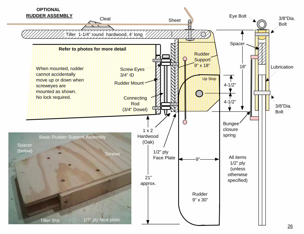
21”approx.
All items1/2” ply(unless
otherwise specified)
9”
18”
4-1/2”
Up Stop
Rudder 9” x 30”
4-1/2”
Screw Eyes3/4” ID
1 x 2Hardwood
(Oak)
ConnectingRod
(3/4” Dowel)
1/2” plyFace Plate
RUDDER ASSEMBLY
RudderSupport9” x 18”
Rudder Mount
When mounted, rudder cannot accidentally move up or down when screweyes are mounted as shown.No lock required.
Spacer
Basic Rudder Support Assembly
1/2” ply face plate
Screws
Tiller Slot
Spacer(below)
Tiller 1-1/4” round hardwood, 4’ long
Bungee closurespring
Sheet
Refer to photos for more detail
Eye Bolt
3/8”Dia.Bolt
Cleat
Lubrication
3/8”Dia.Bolt
OPTIONAL
27
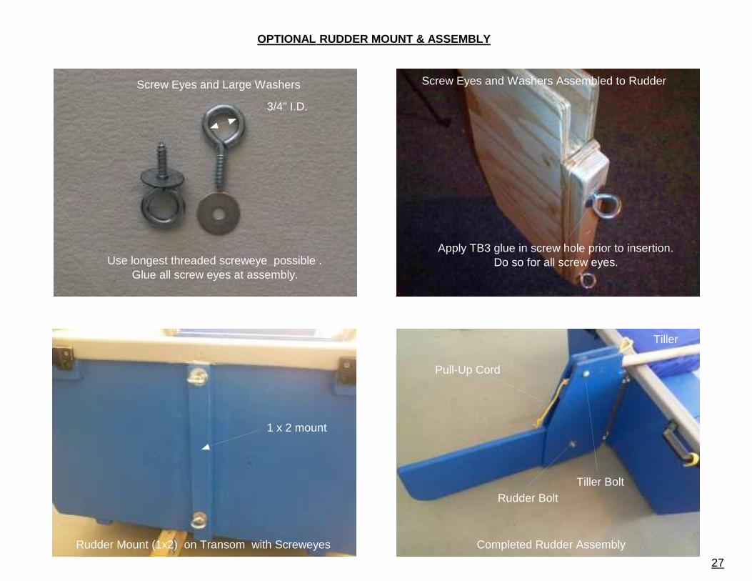
Completed Rudder Assembly
Pull-Up Cord
Tiller BoltRudder Bolt
Rudder Mount (1x2) on Transom with Screweyes
1 x 2 mount
Screw Eyes and Washers Assembled to Rudder
Apply TB3 glue in screw hole prior to insertion.Do so for all screw eyes.
Screw Eyes and Large Washers
Use longest threaded screweye possible .Glue all screw eyes at assembly.
3/4” I.D.
OPTIONAL RUDDER MOUNT & ASSEMBLY
Tiller
28
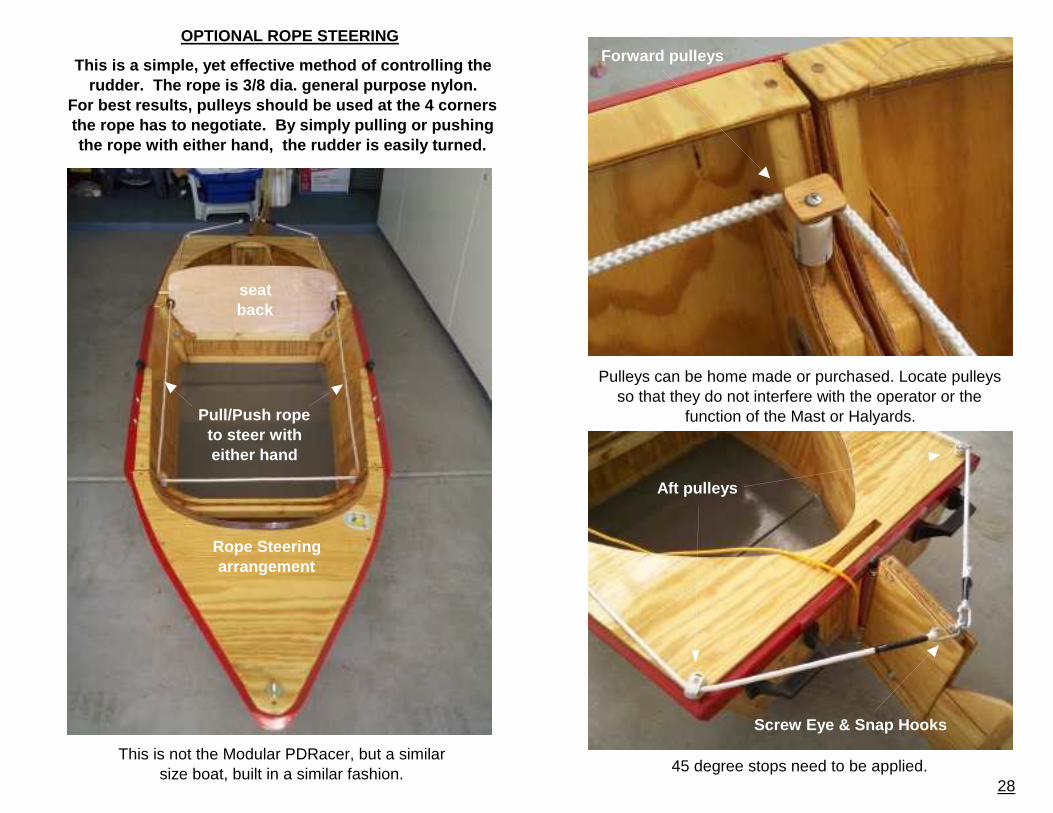
OPTIONAL ROPE STEERING
This is a simple, yet effective method of controlli ng the rudder. The rope is 3/8 dia. general purpose nylon .
For best results, pulleys should be used at the 4 c orners the rope has to negotiate. By simply pulling or pu shing the rope with either hand, the rudder is easily tu rned.
Pulleys can be home made or purchased. Locate pulleys so that they do not interfere with the operator or the
function of the Mast or Halyards.
Aft pulleys
Screw Eye & Snap Hooks
Forward pulleys
Rope Steering arrangement
Pull/Push rope to steer with either hand
seat back
This is not the Modular PDRacer, but a similar size boat, built in a similar fashion. 45 degree stops need to be applied.
1 of 4 pages
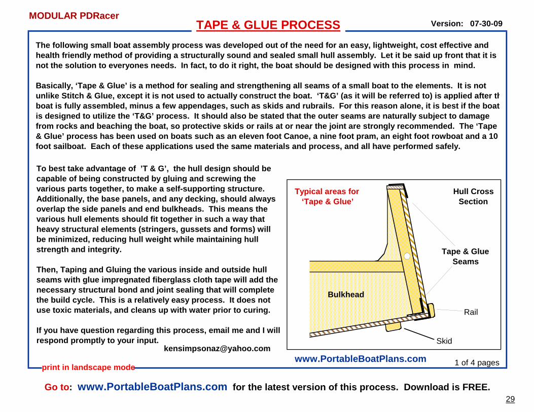
The following small boat assembly process was devel oped out of the need for an easy, lightweight, cost effective and health friendly method of providing a structurally sound and sealed small hull assembly. Let it be sa id up front that it is not the solution to everyones needs. In fact, to d o it right, the boat should be designed with this p rocess in mind.
Basically, ‘Tape & Glue’ is a method for sealing an d strengthening all seams of a small boat to the el ements. It is not unlike Stitch & Glue, except it is not used to actu ally construct the boat. ‘T&G’ (as it will be refe rred to) is applied after the boat is fully assembled, minus a few appendages, su ch as skids and rubrails. For this reason alone, i t is best if the boat is designed to utilize the ‘T&G’ process. It should also be stated that the outer seams are naturally subject to damage from rocks and beaching the boat, so protective ski ds or rails at or near the joint are strongly recom mended. The ‘Tape & Glue’ process has been used on boats such as an e leven foot Canoe, a nine foot pram, an eight foot r owboat and a 10 foot sailboat. Each of these applications used the same materials and process, and all have performed safely.
To best take advantage of ’T & G’, the hull desig n should be capable of being constructed by gluing and screwing the various parts together, to make a self-supporting s tructure. Additionally, the base panels, and any decking, sho uld always overlap the side panels and end bulkheads. This me ans the various hull elements should fit together in such a way that heavy structural elements (stringers, gussets and f orms) will be minimized, reducing hull weight while maintaining hull strength and integrity.
Then, Taping and Gluing the various inside and outs ide hull seams with glue impregnated fiberglass cloth tape will add the necessary structural bond and joint sealing that wi ll complete the build cycle. This is a relatively easy process . It does not use toxic materials, and cleans up with water prior to curing.
If you have question regarding this process, email me and I will respond promptly to your input.
TAPE & GLUE PROCESS 07-30-09
print in landscape mode
Version:
Hull Cross Section
Tape & Glue Seams
Bulkhead
Typical areas for ‘Tape & Glue’
Skid
Rail
www.PortableBoatPlans.com
Go to : www.PortableBoatPlans.com for the latest version of this process. Download is FREE.29
MODULAR PDRacer
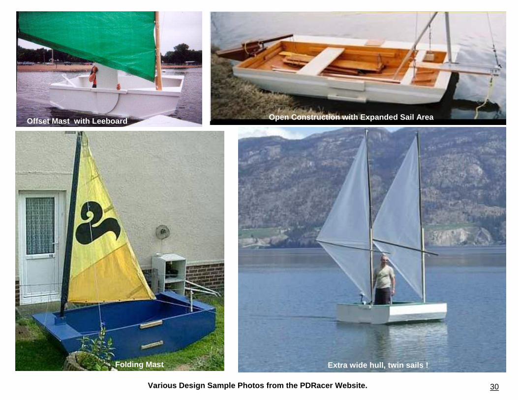
Various Design Sample Photos from the PDRacer Websi te. 30
Folding Mast Extra wide hull, twin sails !
Offset Mast with Leeboard Open Construction with Expanded Sail Area
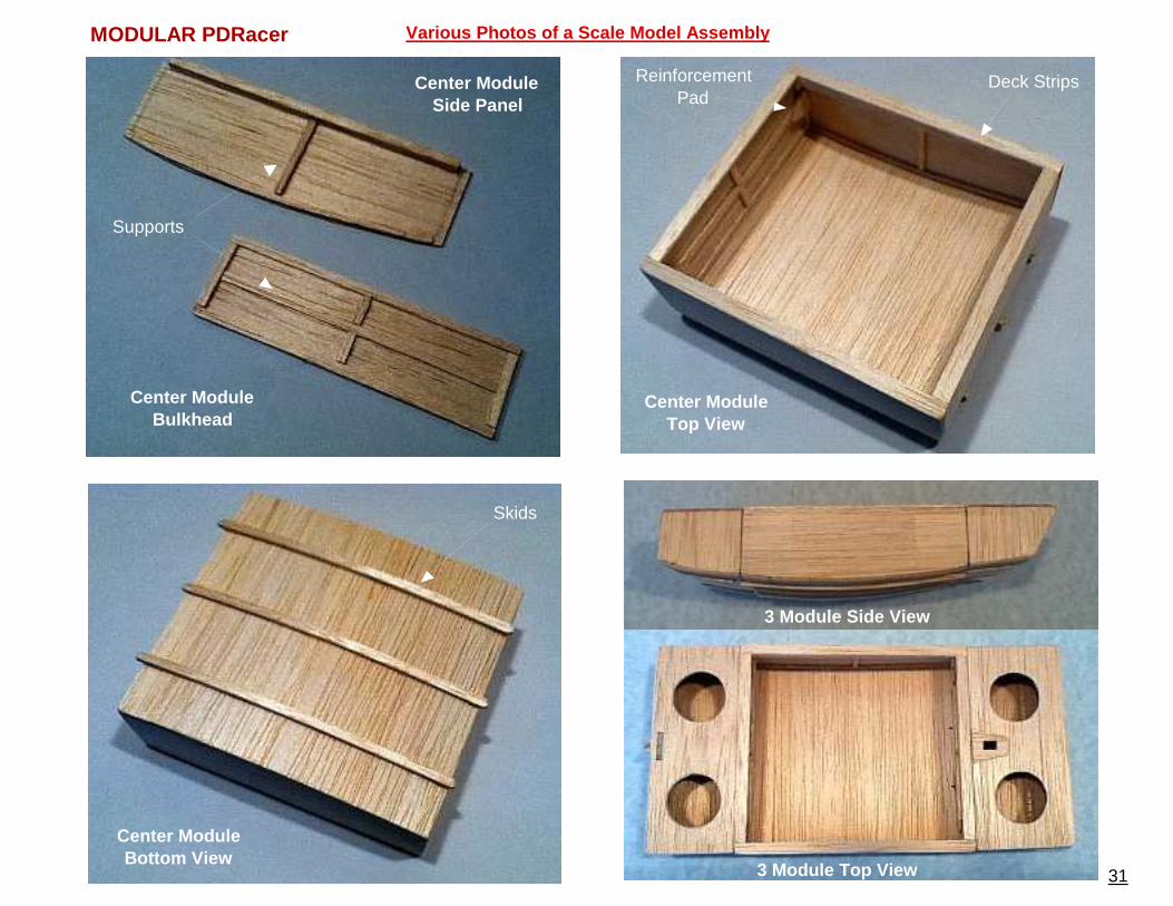
Various Photos of a Scale Model Assembly
31
Center ModuleTop View
Deck StripsReinforcement Pad
Center ModuleBottom View
Skids
MODULAR PDRacer
Center ModuleSide Panel
Center ModuleBulkhead
Supports
3 Module Side View
3 Module Top View
32
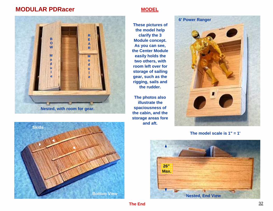
MODULAR PDRacer
6' Power Ranger
The End
Nested, with room for gear.
BOW
Module
REAR
Module
Bottom View
Skids
Nested, End View
26"Max.
These pictures of the model help
clarify the 3 Module concept. As you can see,
the Center Module easily holds the two others, with
room left over for storage of sailing gear, such as the rigging, sails and
the rudder.
The photos also illustrate the
spaciousness of the cabin, and the storage areas fore
and aft.
The model scale is 1" = 1'
MODEL