Embed Size (px)
Citation preview
www.Quadrevo.com
MOGO250
FPV 250 class Quadcopter
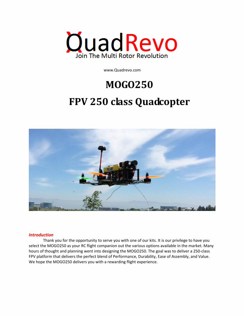
Introduction Thank you for the opportunity to serve you with one of our kits. It is our privilege to have you
select the MOGO250 as your RC flight companion out the various options available in the market. Many hours of thought and planning went into designing the MOGO250. The goal was to deliver a 250-class FPV platform that delivers the perfect blend of Performance, Durability, Ease of Assembly, and Value. We hope the MOGO250 delivers you with a rewarding flight experience.
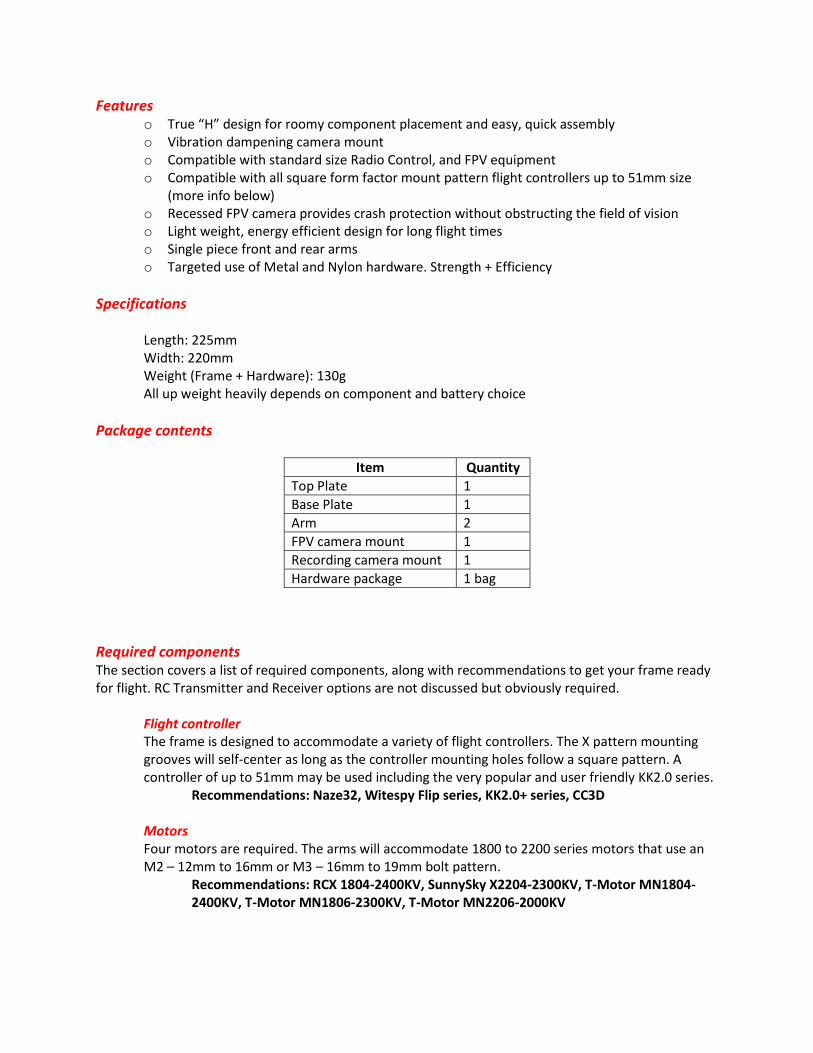
Features o True “H” design for roomy component placement and easy, quick assembly o Vibration dampening camera mount o Compatible with standard size Radio Control, and FPV equipment o Compatible with all square form factor mount pattern flight controllers up to 51mm size
(more info below) o Recessed FPV camera provides crash protection without obstructing the field of vision o Light weight, energy efficient design for long flight times o Single piece front and rear arms o Targeted use of Metal and Nylon hardware. Strength + Efficiency
Specifications
Length: 225mm Width: 220mm Weight (Frame + Hardware): 130g All up weight heavily depends on component and battery choice
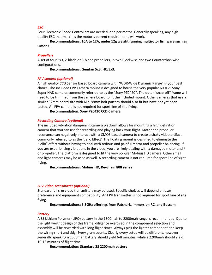
Package contents
Item Quantity
Top Plate 1
Base Plate 1
Arm 2
FPV camera mount 1
Recording camera mount 1
Hardware package 1 bag
Required components The section covers a list of required components, along with recommendations to get your frame ready for flight. RC Transmitter and Receiver options are not discussed but obviously required.
Flight controller The frame is designed to accommodate a variety of flight controllers. The X pattern mounting grooves will self-center as long as the controller mounting holes follow a square pattern. A controller of up to 51mm may be used including the very popular and user friendly KK2.0 series. Recommendations: Naze32, Witespy Flip series, KK2.0+ series, CC3D Motors Four motors are required. The arms will accommodate 1800 to 2200 series motors that use an M2 – 12mm to 16mm or M3 – 16mm to 19mm bolt pattern.
Recommendations: RCX 1804-2400KV, SunnySky X2204-2300KV, T-Motor MN1804-2400KV, T-Motor MN1806-2300KV, T-Motor MN2206-2000KV
ESC Four Electronic Speed Controllers are needed, one per motor. Generally speaking, any high quality ESC that matches the motor’s current requirements will work. Recommendations: 10A to 12A, under 12g weight running multirotor firmware such as SimonK. Propellers A set of four 5x3, 2-blade or 3-blade propellers, in two Clockwise and two Counterclockwise configurations. Recommendations: Gemfan 5x3, HQ 5x3. FPV camera (optional) A high quality CCD Sensor based board camera with “WDR-Wide Dynamic Range” is your best choice. The included FPV Camera mount is designed to house the very popular 600TVL Sony Super HAD camera, commonly referred to as the “Sony PZ0420”. The outer “snap-off” frame will need to be trimmed from the camera board to fit the included mount. Other cameras that use a similar 32mm board size with M2-28mm bolt pattern should also fit but have not yet been tested. An FPV camera is not required for sport line of site flying. Recommendation: Sony PZ0420 CCD Camera Recording Camera (optional) The included vibration dampening camera platform allows for mounting a high definition camera that you can use for recording and playing back your flight. Motor and propeller resonance can negatively interact with a CMOS based camera to create a shaky video artifact commonly referred to as the “Jello Effect” The floating mount is designed to eliminate the “Jello” effect without having to deal with tedious and painful motor and propeller balancing. If you are experiencing vibrations in the video, you are likely dealing with a damaged motor and / or propeller. The platform is designed to fit the very popular Mobius HD camera. Other small and light cameras may be used as well. A recording camera is not required for sport line of sight flying. Recommendations: Mobius HD, Keychain 808 series FPV Video Transmitter (optional) Standard full size video transmitters may be used. Specific choices will depend on user preference and equipment compatibility. An FPV transmitter is not required for sport line of site flying. Recommendations: 5.8GHz offerings from Fatshark, Immersion RC, and Boscam Battery A 3S Lithium Polymer (LIPO) battery in the 1300mah to 2200mah range is recommended. Due to the light weight design of this frame, diligence exercised in the component selection and assembly will be rewarded with long flight times. Always pick the lighter component and keep the wiring short and tidy. Every gram counts. Clearly every setup will be different, however generally speaking a 1350mah battery should yield 6-8 minutes, while a 2200mah should yield 10-13 minutes of flight time. Recommendation: Standard 3S 2200mah battery
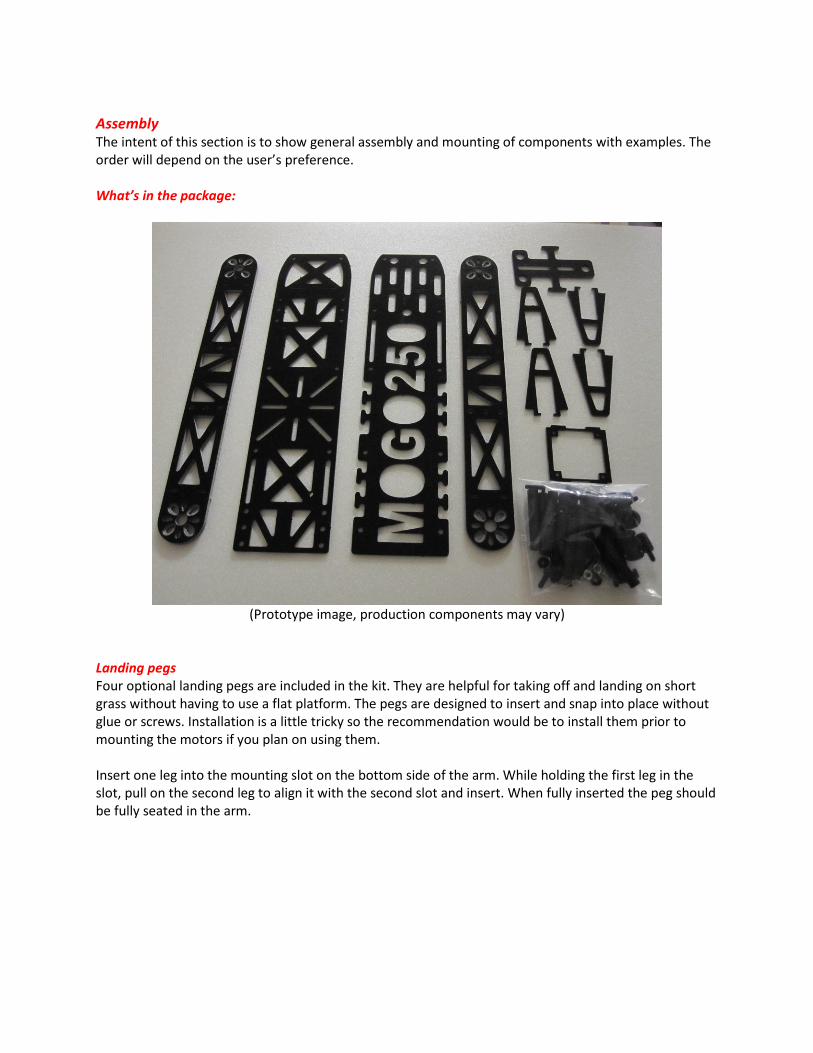
Assembly The intent of this section is to show general assembly and mounting of components with examples. The order will depend on the user’s preference. What’s in the package:
(Prototype image, production components may vary)
Landing pegs Four optional landing pegs are included in the kit. They are helpful for taking off and landing on short grass without having to use a flat platform. The pegs are designed to insert and snap into place without glue or screws. Installation is a little tricky so the recommendation would be to install them prior to mounting the motors if you plan on using them. Insert one leg into the mounting slot on the bottom side of the arm. While holding the first leg in the slot, pull on the second leg to align it with the second slot and insert. When fully inserted the peg should be fully seated in the arm.
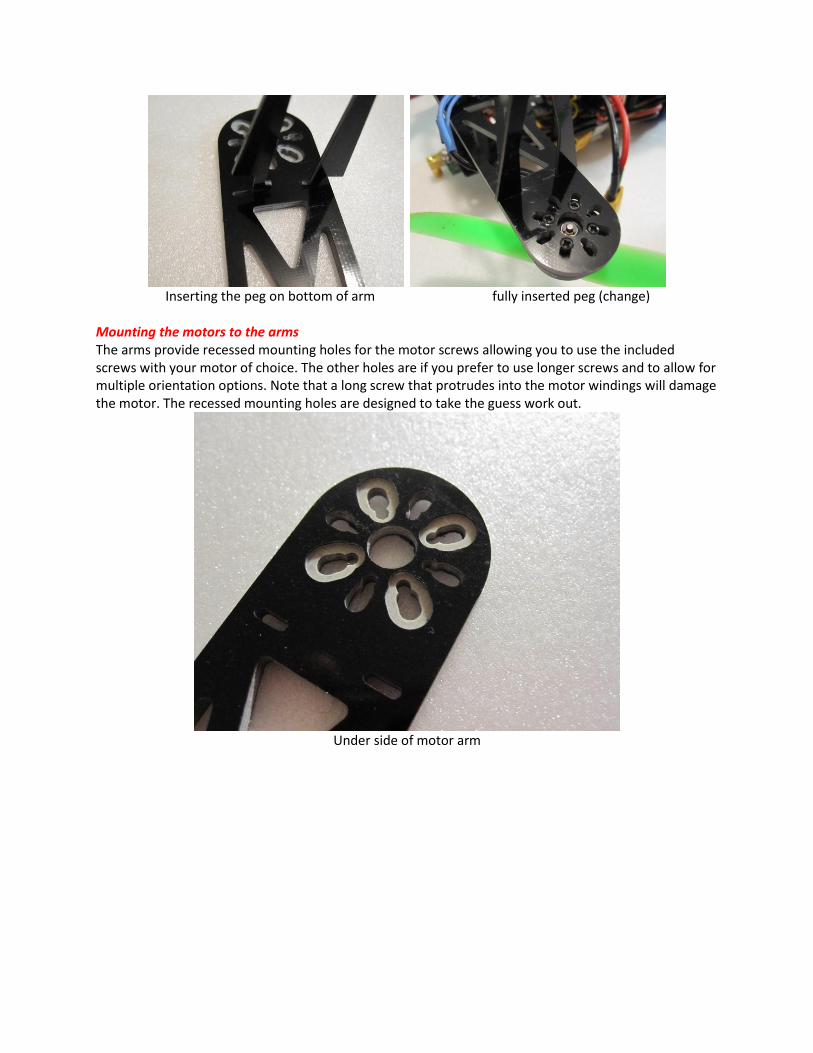
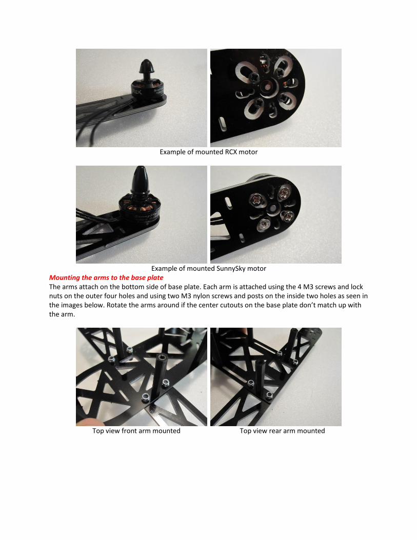
Inserting the peg on bottom of arm fully inserted peg (change) Mounting the motors to the arms The arms provide recessed mounting holes for the motor screws allowing you to use the included screws with your motor of choice. The other holes are if you prefer to use longer screws and to allow for multiple orientation options. Note that a long screw that protrudes into the motor windings will damage the motor. The recessed mounting holes are designed to take the guess work out.
Under side of motor arm
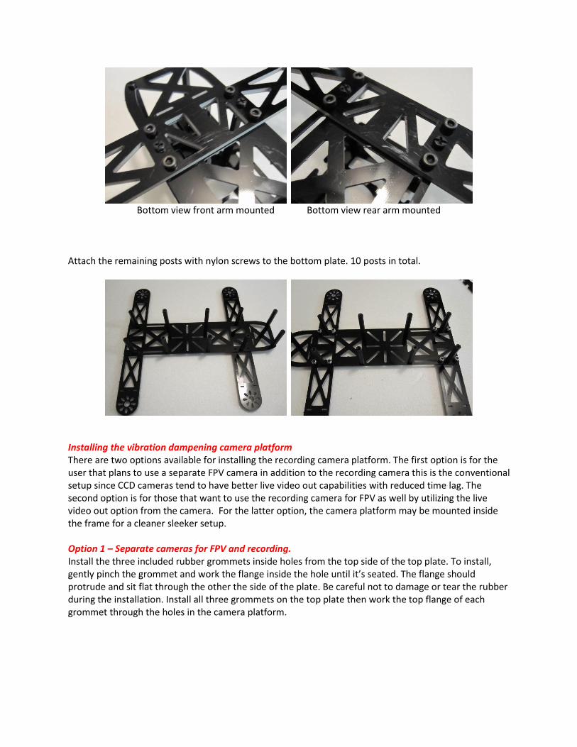
Example of mounted RCX motor
Example of mounted SunnySky motor
Mounting the arms to the base plate The arms attach on the bottom side of base plate. Each arm is attached using the 4 M3 screws and lock nuts on the outer four holes and using two M3 nylon screws and posts on the inside two holes as seen in the images below. Rotate the arms around if the center cutouts on the base plate don’t match up with the arm.
Top view front arm mounted Top view rear arm mounted
Bottom view front arm mounted Bottom view rear arm mounted
Attach the remaining posts with nylon screws to the bottom plate. 10 posts in total.
Installing the vibration dampening camera platform There are two options available for installing the recording camera platform. The first option is for the user that plans to use a separate FPV camera in addition to the recording camera this is the conventional setup since CCD cameras tend to have better live video out capabilities with reduced time lag. The second option is for those that want to use the recording camera for FPV as well by utilizing the live video out option from the camera. For the latter option, the camera platform may be mounted inside the frame for a cleaner sleeker setup. Option 1 – Separate cameras for FPV and recording. Install the three included rubber grommets inside holes from the top side of the top plate. To install, gently pinch the grommet and work the flange inside the hole until it’s seated. The flange should protrude and sit flat through the other the side of the plate. Be careful not to damage or tear the rubber during the installation. Install all three grommets on the top plate then work the top flange of each grommet through the holes in the camera platform.
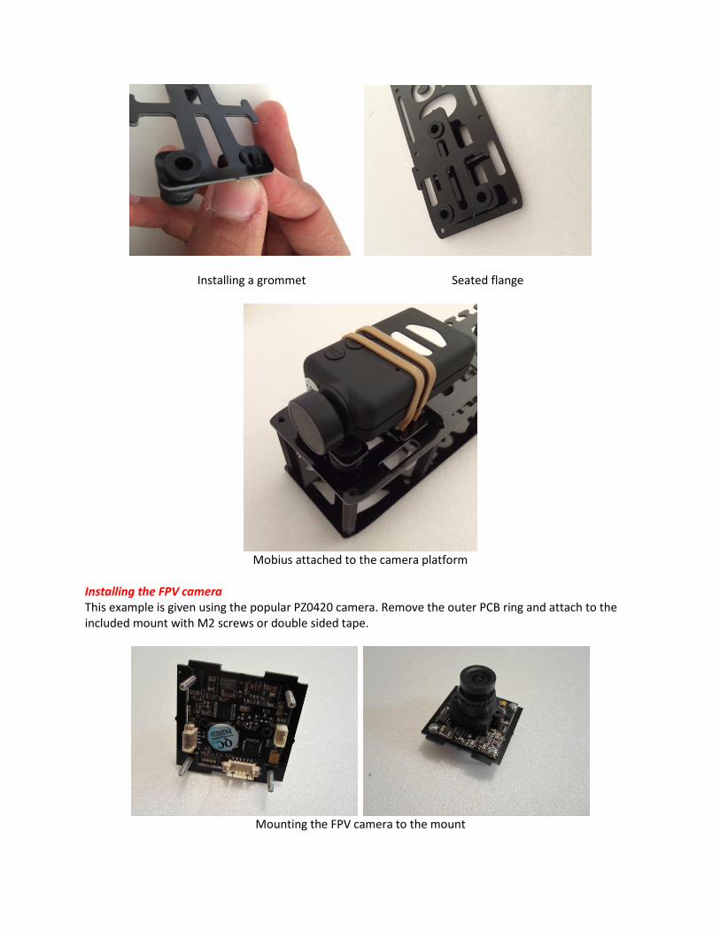
Installing a grommet Seated flange
Mobius attached to the camera platform
Installing the FPV camera This example is given using the popular PZ0420 camera. Remove the outer PCB ring and attach to the included mount with M2 screws or double sided tape.
Mounting the FPV camera to the mount
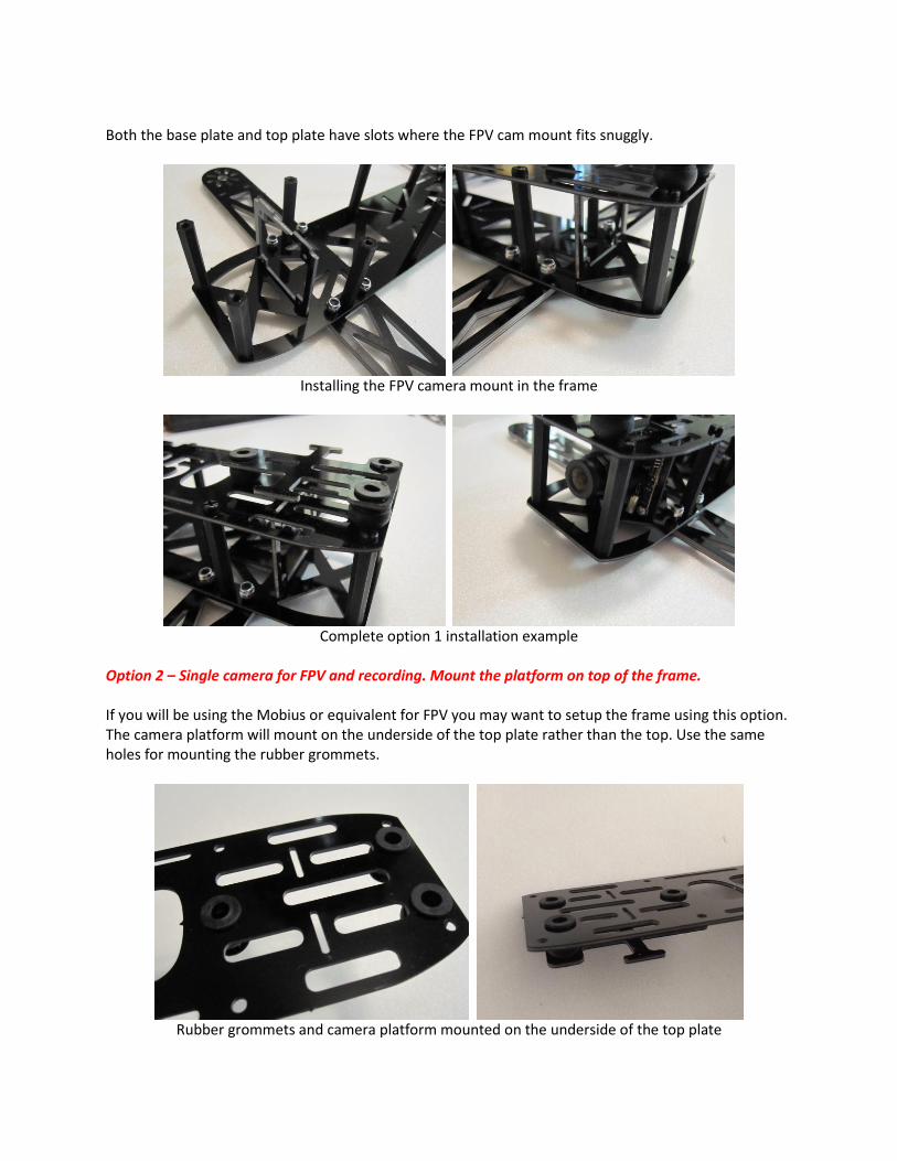
Both the base plate and top plate have slots where the FPV cam mount fits snuggly.
Installing the FPV camera mount in the frame
Complete option 1 installation example
Option 2 – Single camera for FPV and recording. Mount the platform on top of the frame. If you will be using the Mobius or equivalent for FPV you may want to setup the frame using this option. The camera platform will mount on the underside of the top plate rather than the top. Use the same holes for mounting the rubber grommets.
Rubber grommets and camera platform mounted on the underside of the top plate
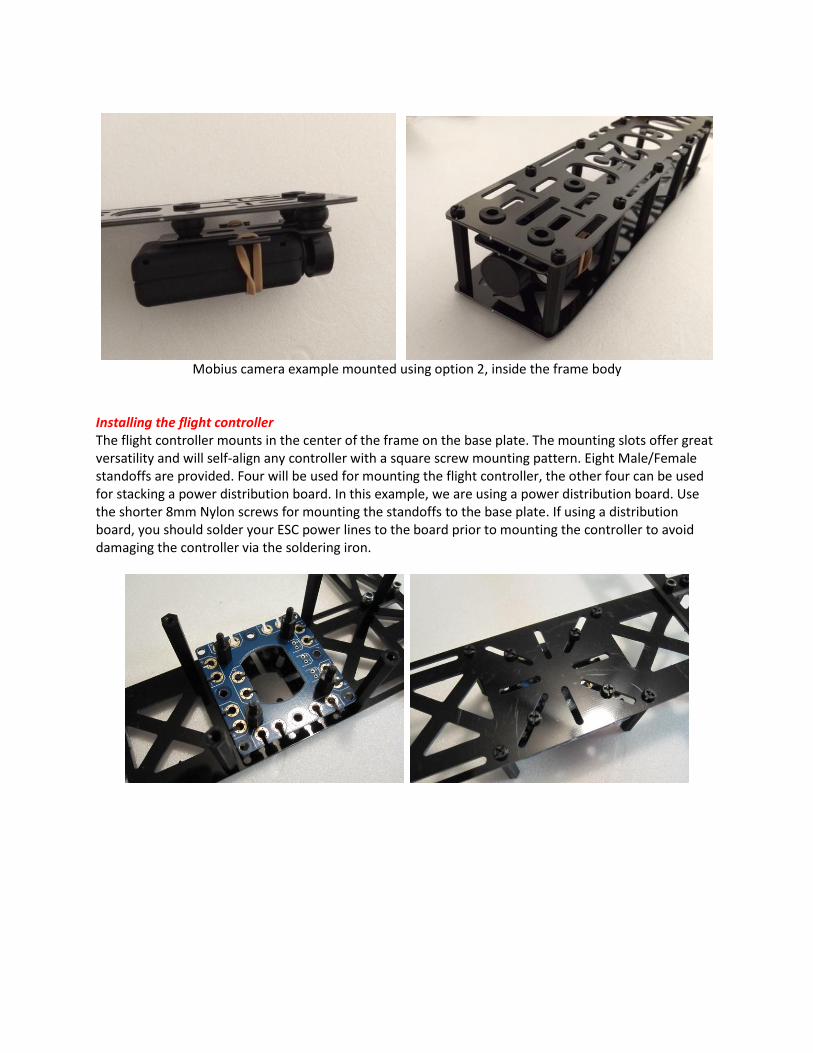
Mobius camera example mounted using option 2, inside the frame body
Installing the flight controller The flight controller mounts in the center of the frame on the base plate. The mounting slots offer great versatility and will self-align any controller with a square screw mounting pattern. Eight Male/Female standoffs are provided. Four will be used for mounting the flight controller, the other four can be used for stacking a power distribution board. In this example, we are using a power distribution board. Use the shorter 8mm Nylon screws for mounting the standoffs to the base plate. If using a distribution board, you should solder your ESC power lines to the board prior to mounting the controller to avoid damaging the controller via the soldering iron.
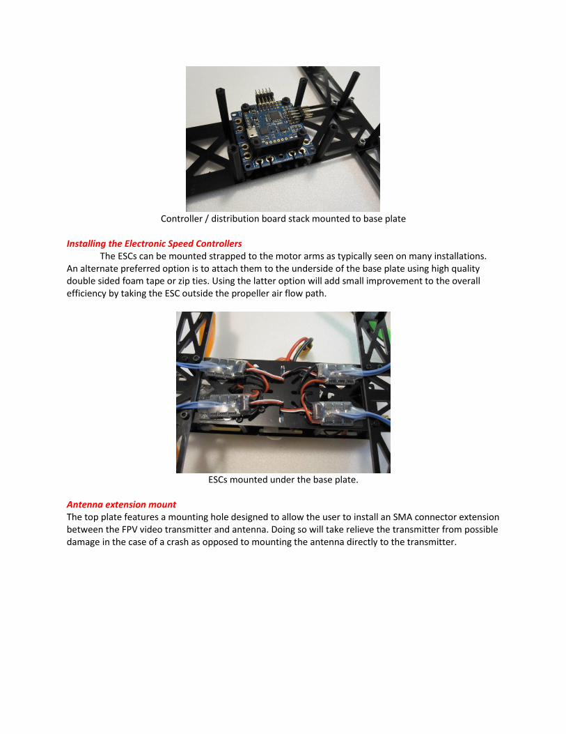
Controller / distribution board stack mounted to base plate
Installing the Electronic Speed Controllers The ESCs can be mounted strapped to the motor arms as typically seen on many installations. An alternate preferred option is to attach them to the underside of the base plate using high quality double sided foam tape or zip ties. Using the latter option will add small improvement to the overall efficiency by taking the ESC outside the propeller air flow path.
ESCs mounted under the base plate.
Antenna extension mount The top plate features a mounting hole designed to allow the user to install an SMA connector extension between the FPV video transmitter and antenna. Doing so will take relieve the transmitter from possible damage in the case of a crash as opposed to mounting the antenna directly to the transmitter.
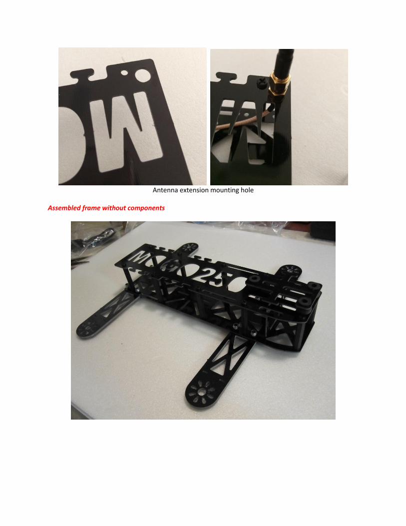
Antenna extension mounting hole
Assembled frame without components