Embed Size (px)
Citation preview

Eric Henry
Moldflow Insight Advanced
Processes
This presentation may contain forward-looking statements about future results, performance or
achievements, financial and otherwise, including statements regarding our guidance for our quarterly and
financial year results.
These statements reflect management’s current expectations, estimates and assumptions based on the
information currently available to Autodesk. These forward-looking statements are not guarantees of future
performance and involve significant risks, uncertainties and other factors that may cause
Autodesk’s actual results, performance or achievements to be materially different from results, performance
or achievements expressed or implied by the forward-looking statements contained in this presentation. A
discussion of the factors that may affect future results is contained in Autodesk’s most recent SEC Form 10-
K and Form 10-Q filings, including descriptions of the risk factors that may impact Autodesk and the
forward-looking statements made in this presentation. If this presentation is reviewed after the time and
date this presentation was first recorded, even if it subsequently is made available by Autodesk, on its Web
site or otherwise, this presentation may not contain current or accurate information.
Autodesk disclaims any obligation to update or revise any forward-looking statement based on new
information, future events or otherwise.
Safe Harbor Statement
SMC Compression Molding
Resin Transfer Molding
Powder Injection Molding
Microcellular & Chemical Foam Molding
Agenda
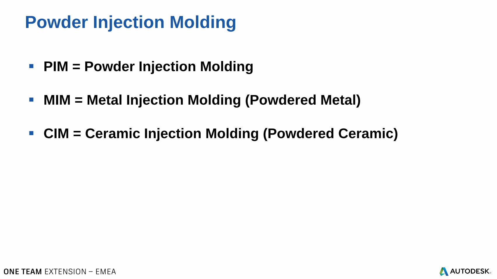
PIM = Powder Injection Molding
MIM = Metal Injection Molding (Powdered Metal)
CIM = Ceramic Injection Molding (Powdered Ceramic)
Powder Injection Molding
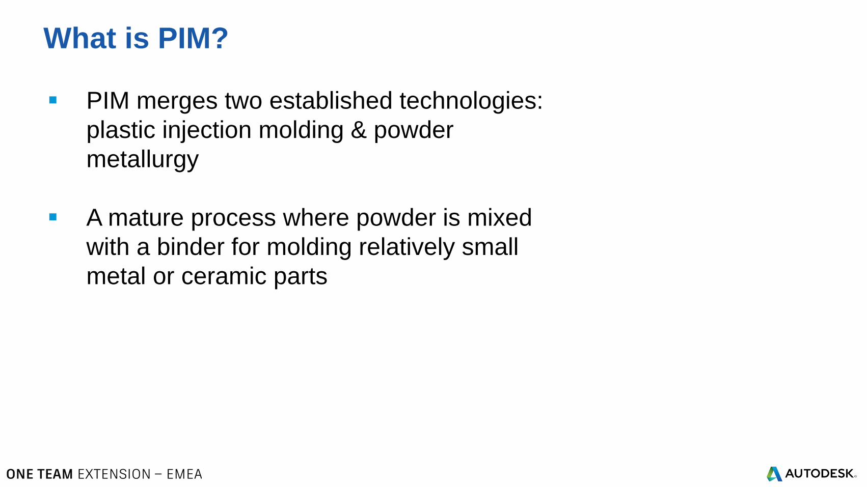
What is PIM?
PIM merges two established technologies:
plastic injection molding & powder
metallurgy
A mature process where powder is mixed
with a binder for molding relatively small
metal or ceramic parts
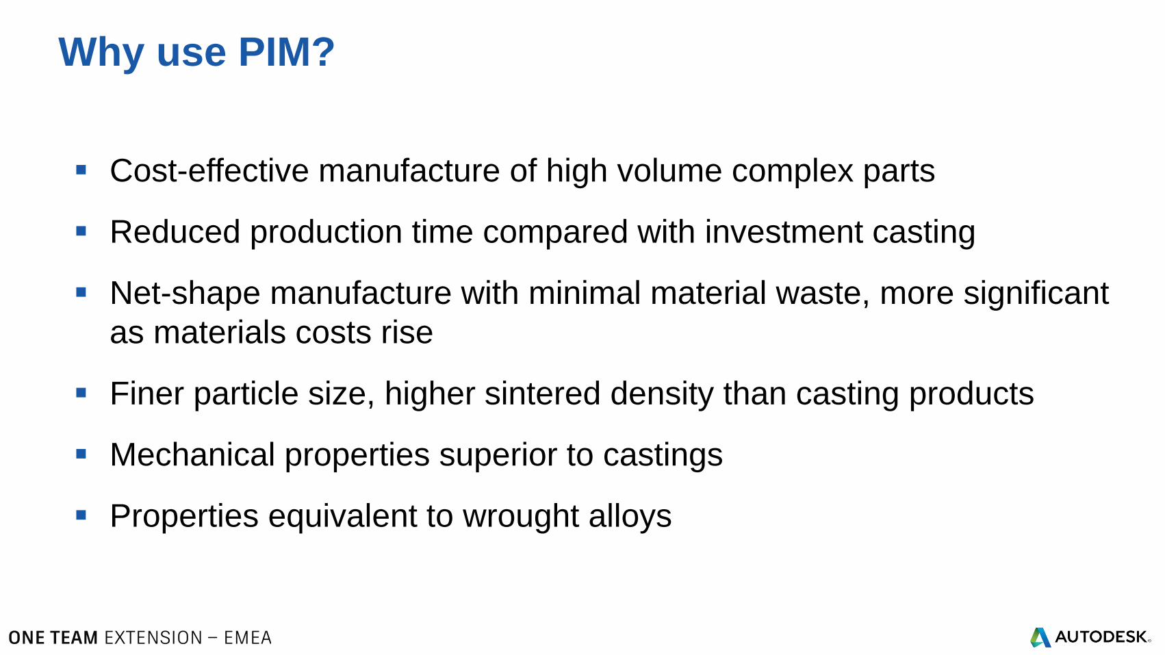
Cost-effective manufacture of high volume complex parts
Reduced production time compared with investment casting
Net-shape manufacture with minimal material waste, more significant
as materials costs rise
Finer particle size, higher sintered density than casting products
Mechanical properties superior to castings
Properties equivalent to wrought alloys
Why use PIM?
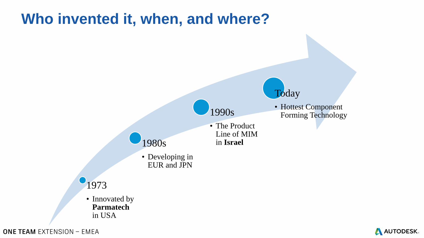
Who invented it, when, and where?
1973
• Innovated by Parmatechin USA
1980s
• Developing in EUR and JPN
1990s
• The Product Line of MIM in Israel
Today
• Hottest Component Forming Technology
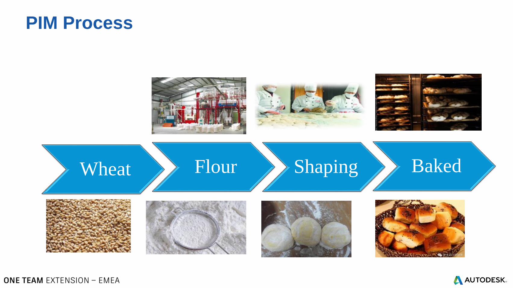
PIM Process
Wheat Flour Shaping Baked
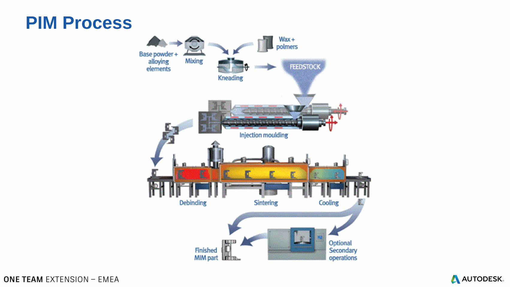
PIM Process
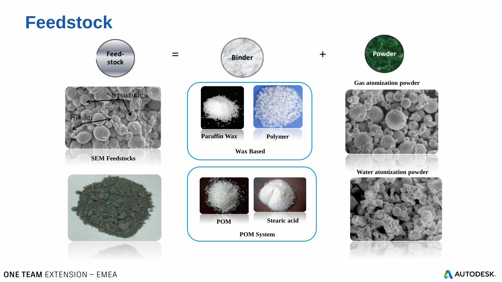
Feedstock
+=
Gas atomization powder
Water atomization powder
Paraffin Wax Polymer
POM Stearic acid
SEM Feedstocks
Wax Based
POM System
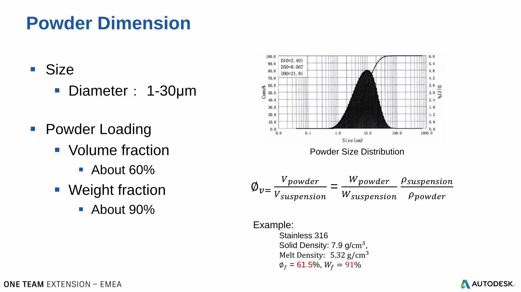
Size
Diameter: 1-30μm
Powder Loading
Volume fraction
About 60%
Weight fraction
About 90%
Powder Dimension
∅𝑣=𝑉𝑝𝑜𝑤𝑑𝑒𝑟
𝑉𝑠𝑢𝑠𝑝𝑒𝑛𝑠𝑖𝑜𝑛=
𝑊𝑝𝑜𝑤𝑑𝑒𝑟
𝑊𝑠𝑢𝑠𝑝𝑒𝑛𝑠𝑖𝑜𝑛
𝜌𝑠𝑢𝑠𝑝𝑒𝑛𝑠𝑖𝑜𝑛
𝜌𝑝𝑜𝑤𝑑𝑒𝑟
Example: Stainless 316
Solid Density: 7.9 g/cm3,Melt Density: 5.32 g/cm3
∅𝑓 = 61.5%, 𝑊𝑓 = 91%
Powder Size Distribution
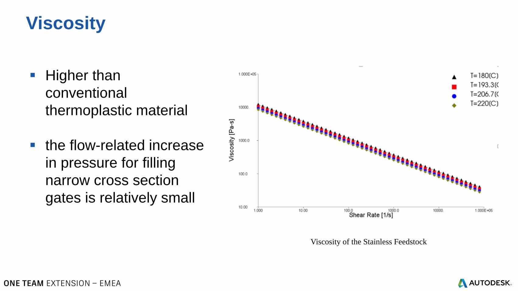
Higher than
conventional
thermoplastic material
the flow-related increase
in pressure for filling
narrow cross section
gates is relatively small
Viscosity
Viscosity of the Stainless Feedstock
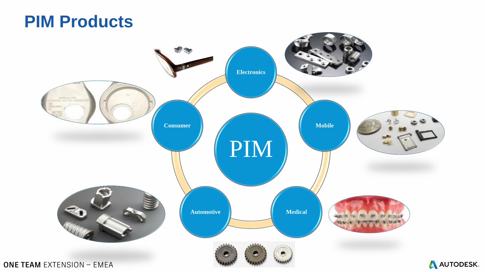
PIM Products
PIM
Electronics
Mobile
MedicalAutomotive
Consumer
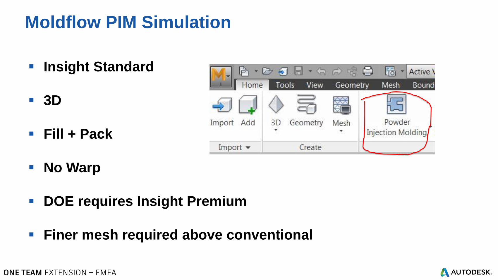
Insight Standard
3D
Fill + Pack
No Warp
DOE requires Insight Premium
Finer mesh required above conventional
Moldflow PIM Simulation
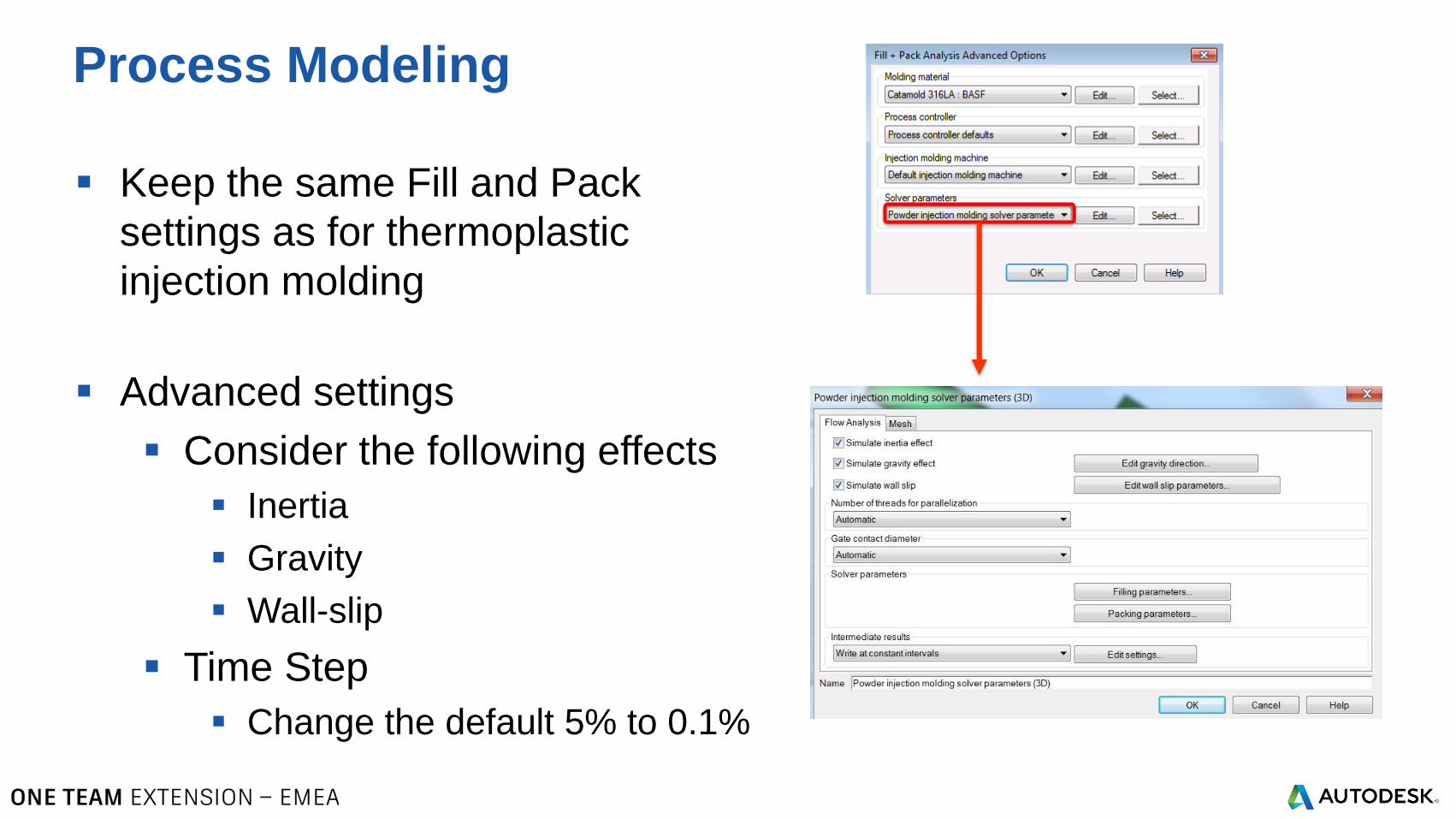
Keep the same Fill and Pack
settings as for thermoplastic
injection molding
Advanced settings
Consider the following effects
Inertia
Gravity
Wall-slip
Time Step
Change the default 5% to 0.1%
Process Modeling
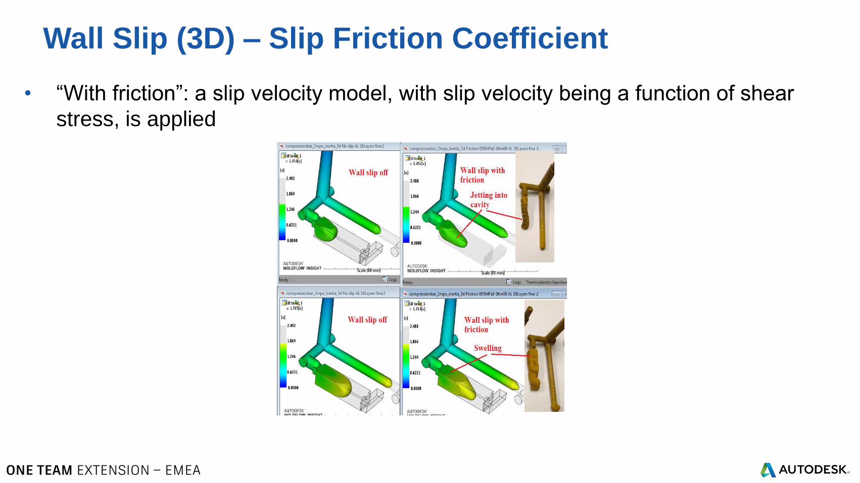
• “With friction”: a slip velocity model, with slip velocity being a function of shear
stress, is applied
Wall Slip (3D) – Slip Friction Coefficient
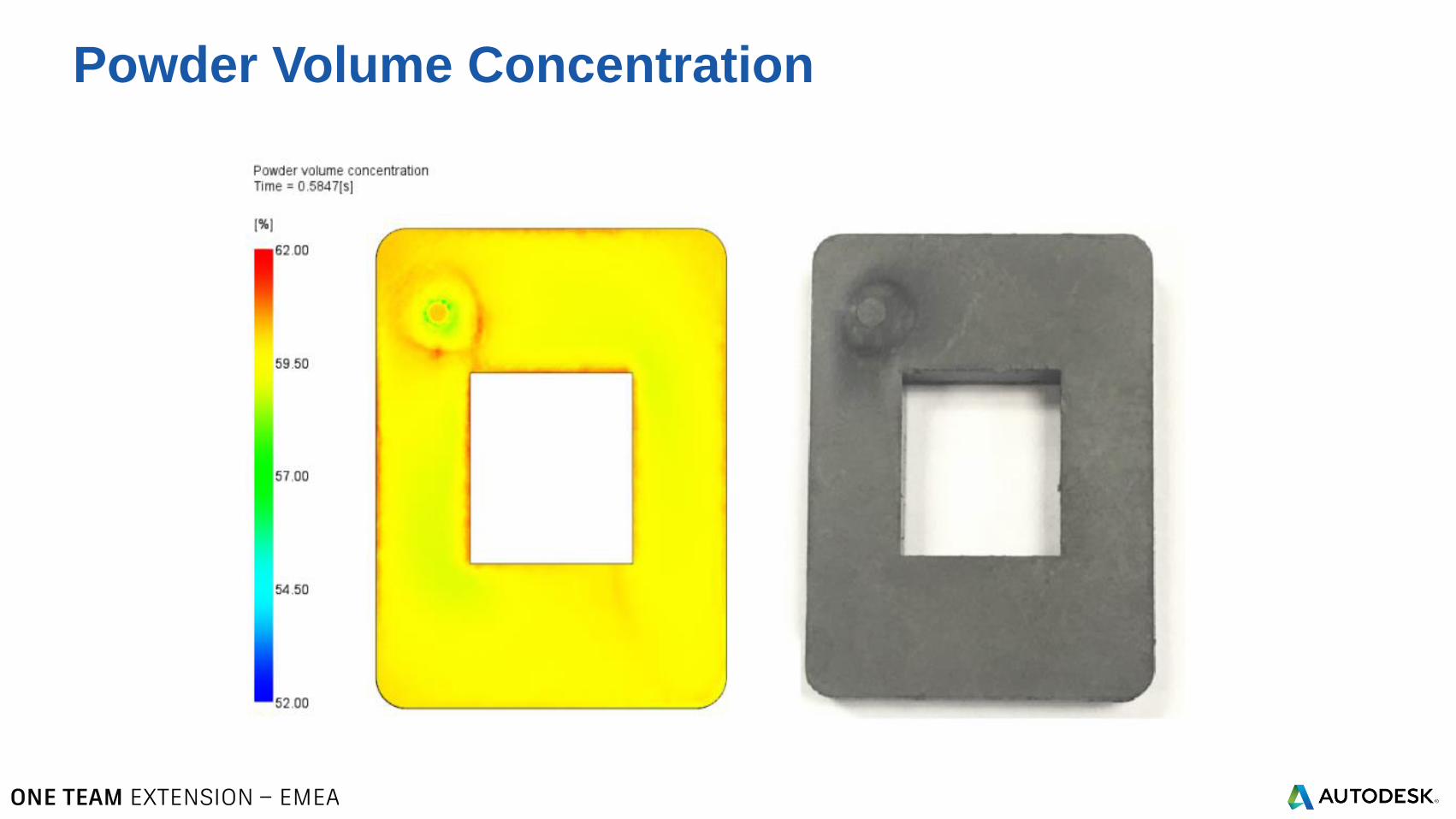
Powder Volume Concentration
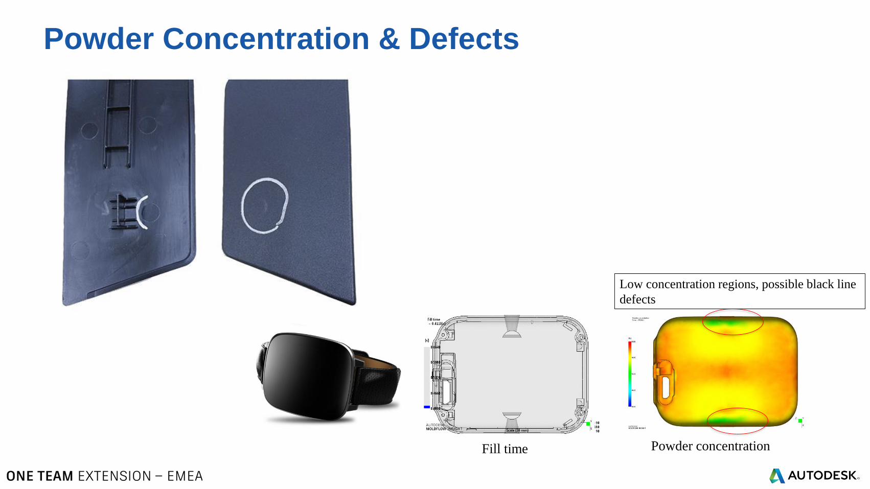
Powder Concentration & Defects
Fill time Powder concentration
Low concentration regions, possible black line
defects
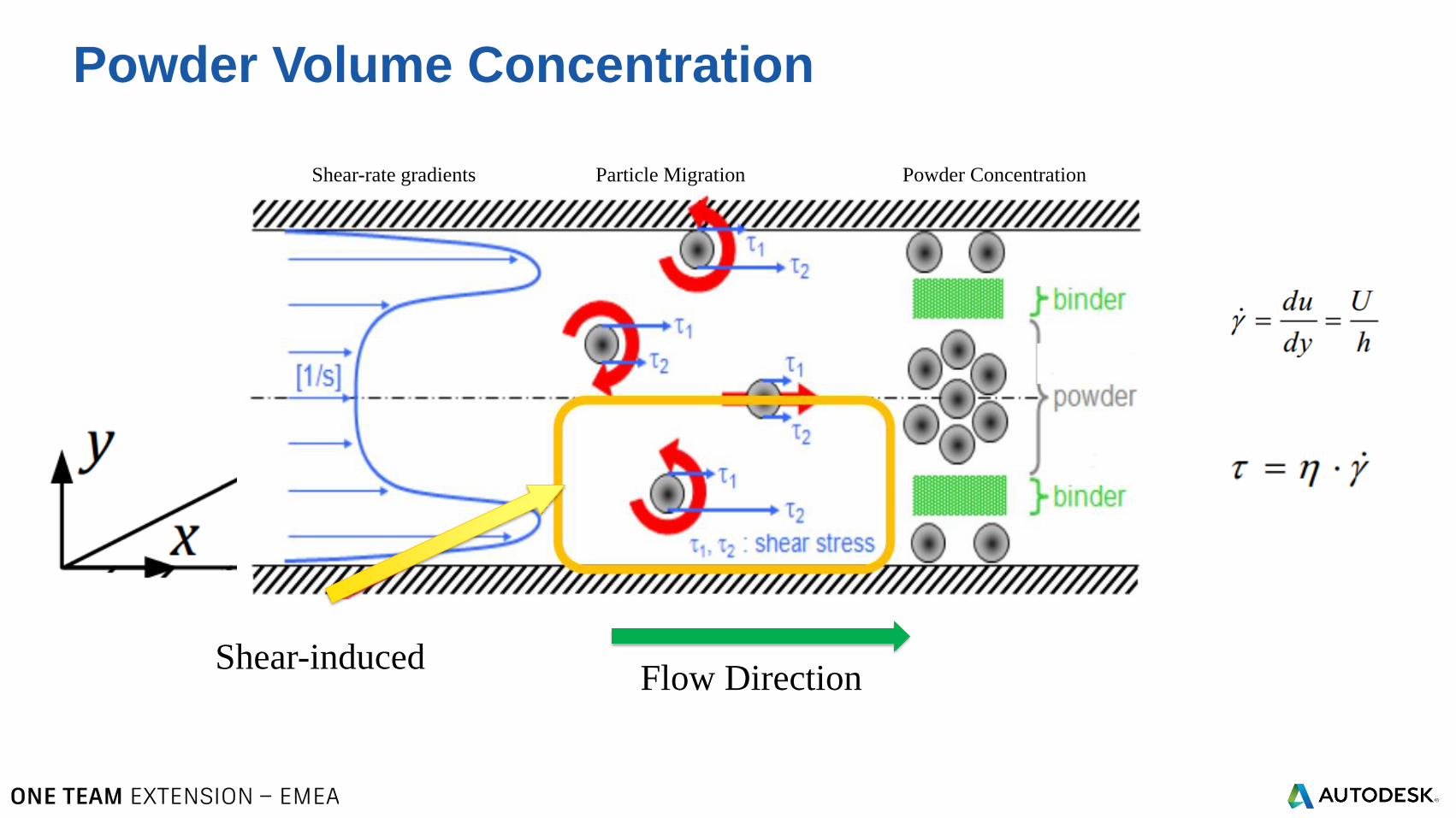
Powder Volume Concentration
Shear-inducedFlow Direction
Shear-rate gradients Particle Migration Powder Concentration
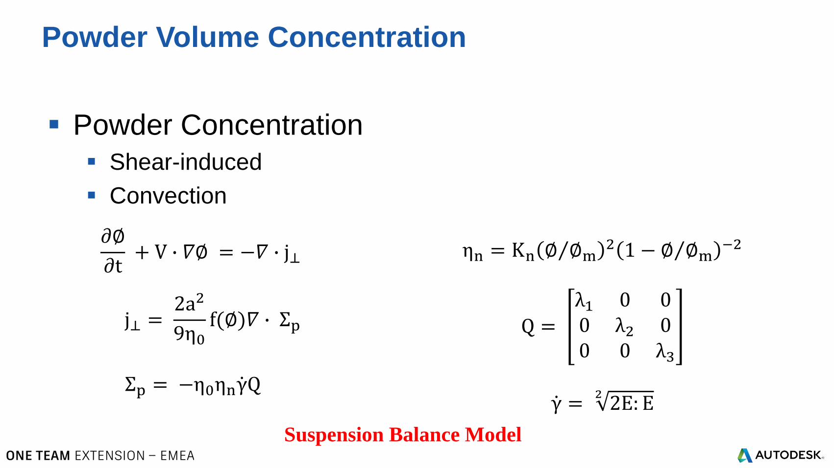
Powder Concentration
Shear-induced
Convection
Powder Volume Concentration
𝜕∅
𝜕t+ V ∙ 𝛻∅ = −𝛻 ∙ j⊥
j⊥ =2a2
9η0f(∅)𝛻 ∙ Σp
Σp = −η0ηn ሶγQ
ηn = Kn Τ∅ ∅m2 1 − Τ∅ ∅m
−2
Q =
λ1 0 00 λ2 00 0 λ3
ሶγ =22E: E
Suspension Balance Model
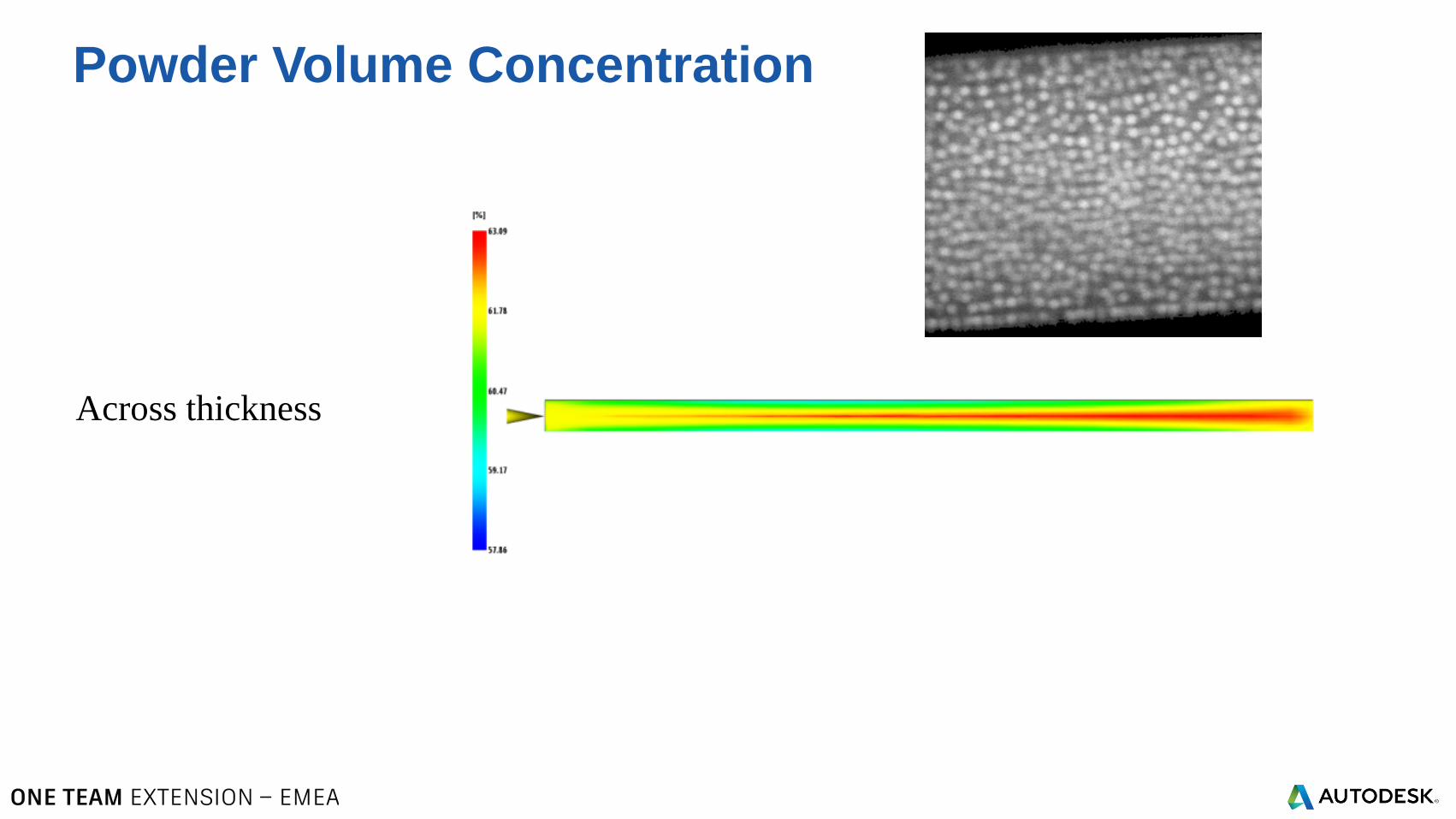
Powder Volume Concentration
Across thickness
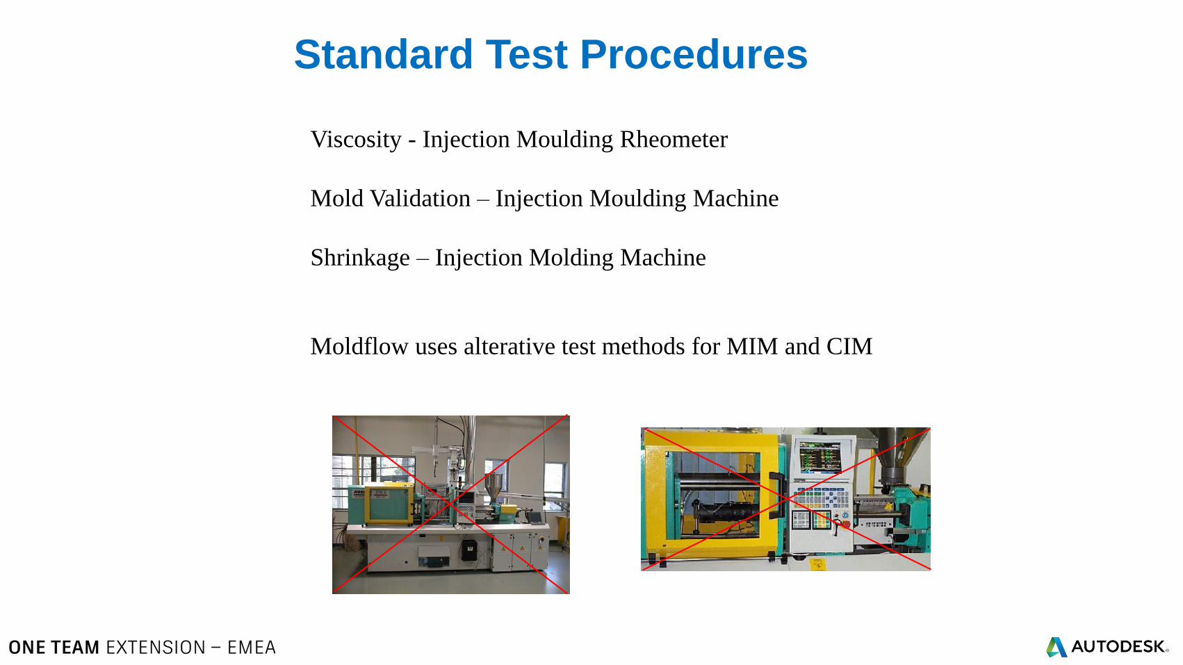
Standard Test Procedures
Viscosity - Injection Moulding Rheometer
Mold Validation – Injection Moulding Machine
Shrinkage – Injection Molding Machine
Moldflow uses alterative test methods for MIM and CIM
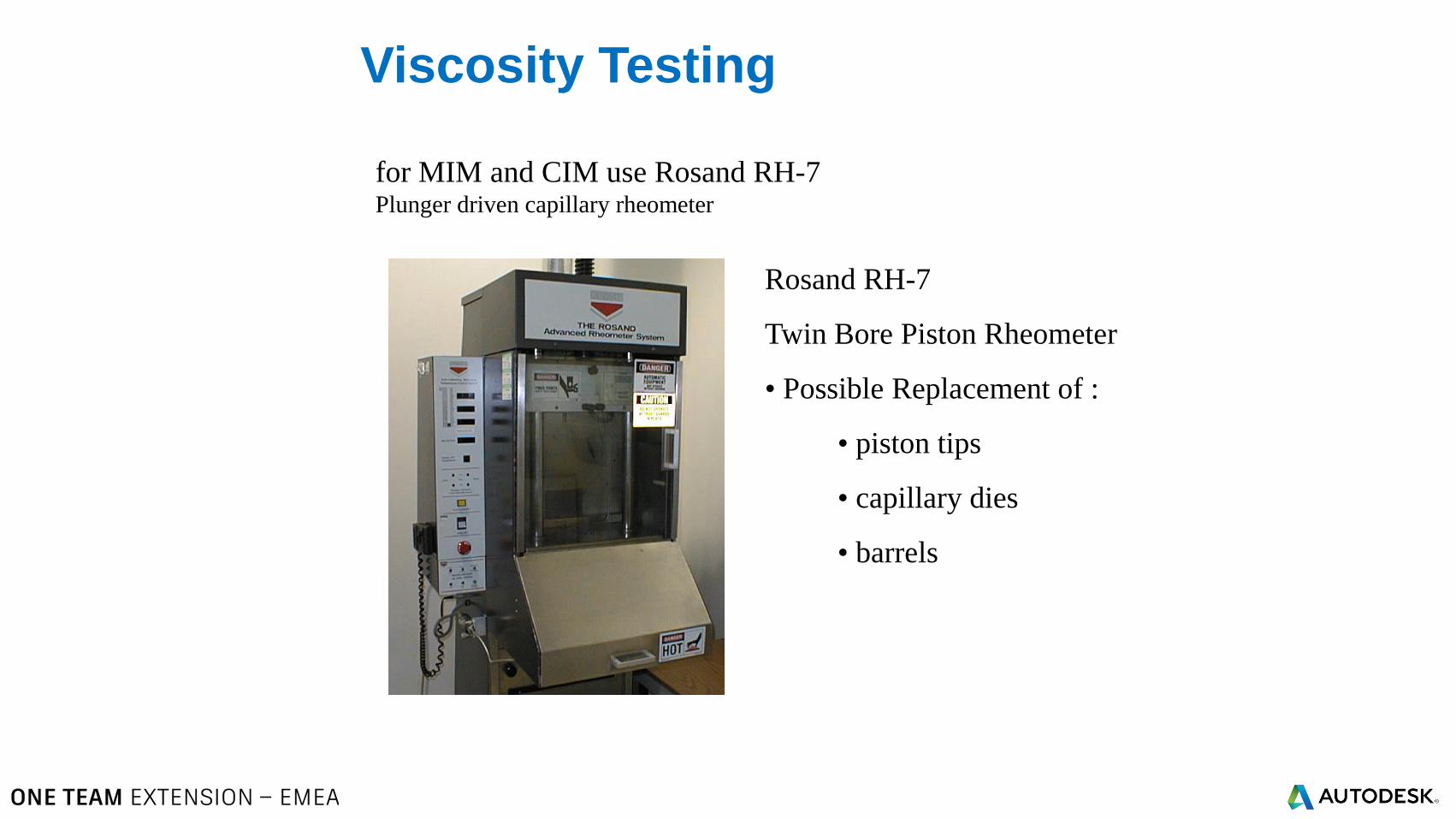
Viscosity Testing
Rosand RH-7
Twin Bore Piston Rheometer
• Possible Replacement of :
• piston tips
• capillary dies
• barrels
for MIM and CIM use Rosand RH-7Plunger driven capillary rheometer
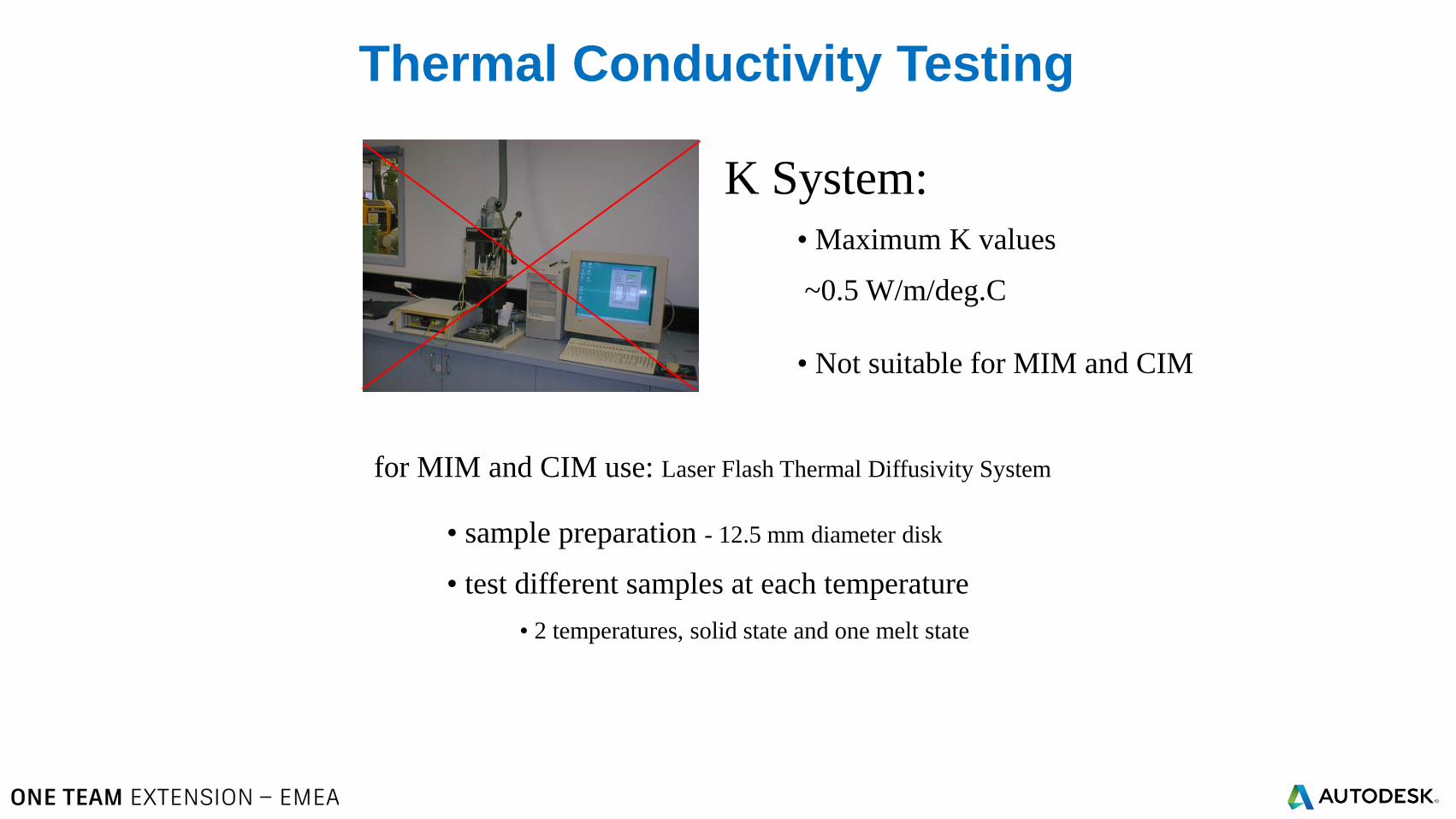
Thermal Conductivity Testing
K System:
• Maximum K values
~0.5 W/m/deg.C
• Not suitable for MIM and CIM
for MIM and CIM use: Laser Flash Thermal Diffusivity System
• sample preparation - 12.5 mm diameter disk
• test different samples at each temperature
• 2 temperatures, solid state and one melt state
© 2016 Autodesk© 2016 Autodesk
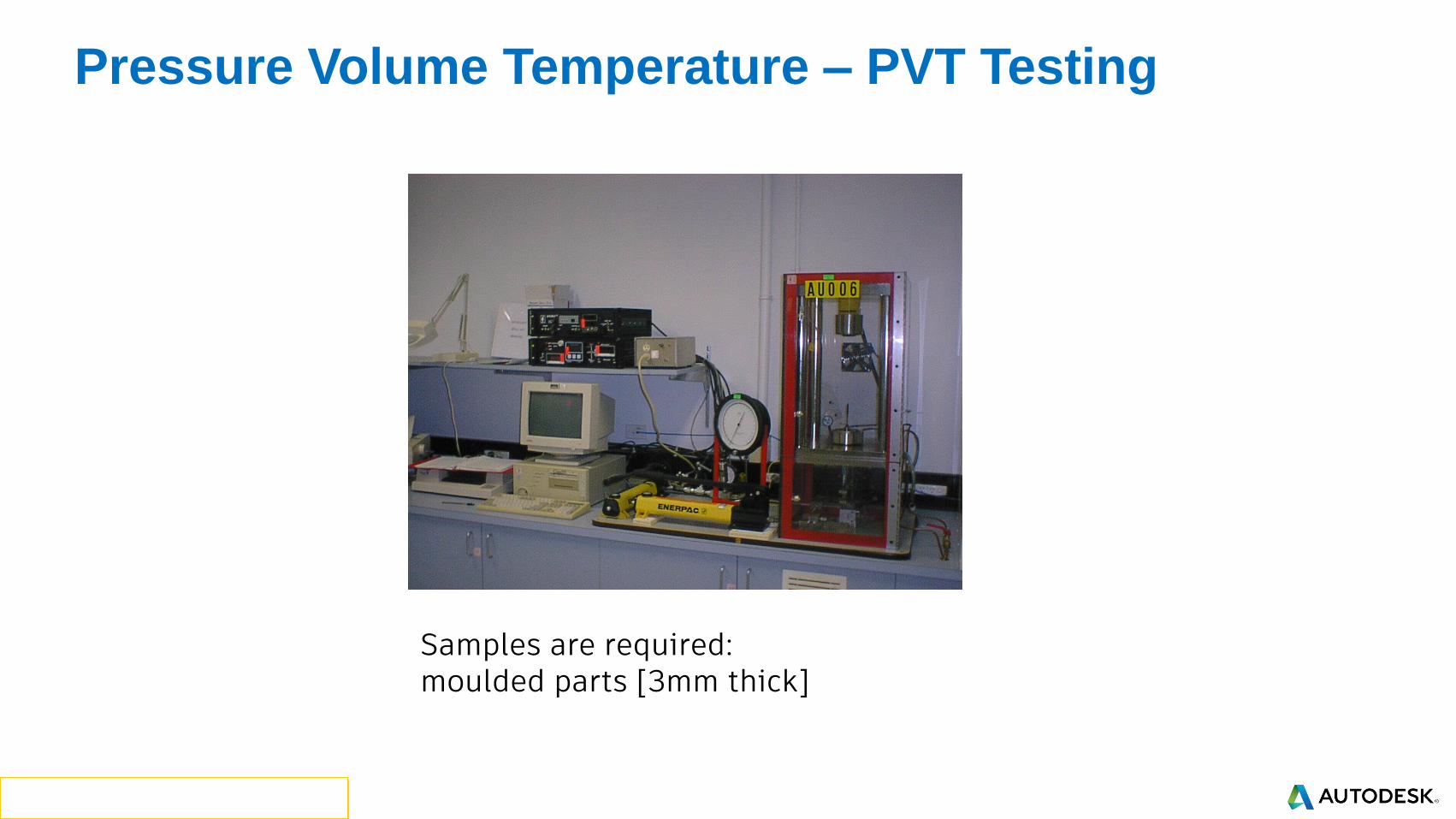
Pressure Volume Temperature – PVT Testing
Samples are required:moulded parts [3mm thick]
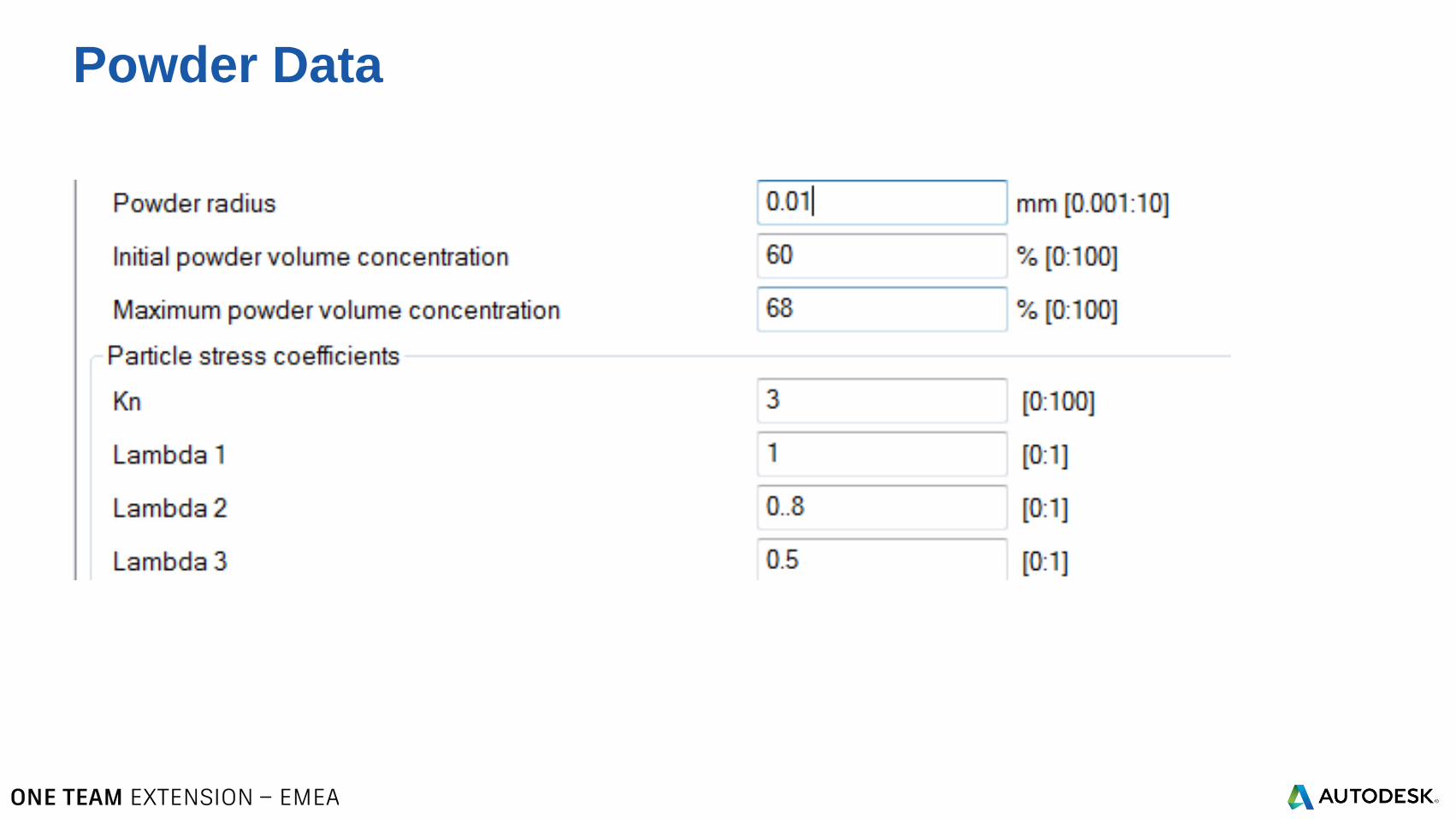
Powder Data
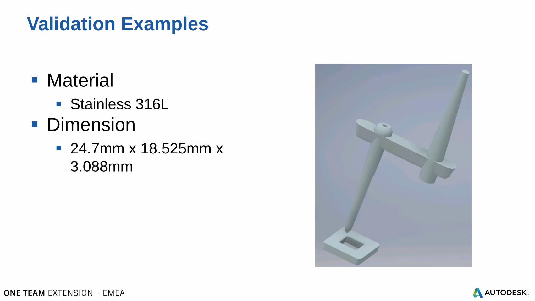
Material
Stainless 316L
Dimension
24.7mm x 18.525mm x
3.088mm
Validation Examples
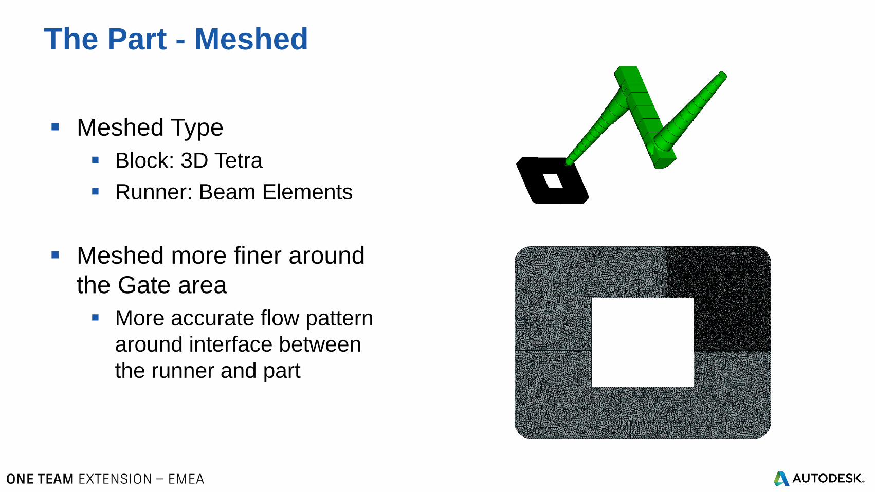
Meshed Type
Block: 3D Tetra
Runner: Beam Elements
Meshed more finer around
the Gate area
More accurate flow pattern
around interface between
the runner and part
The Part - Meshed
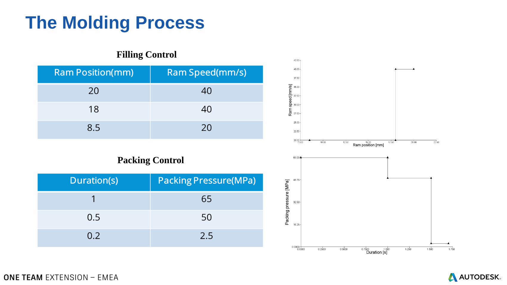
The Molding Process
Filling Control
Packing Control
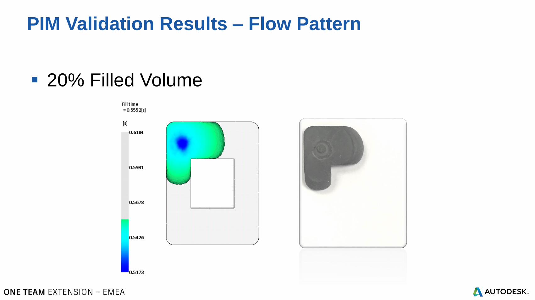
20% Filled Volume
PIM Validation Results – Flow Pattern
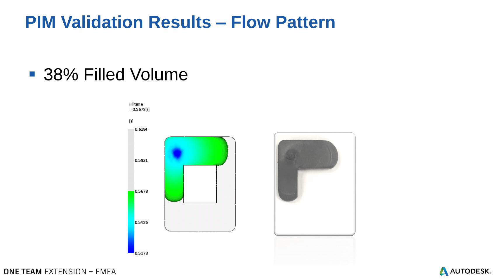
38% Filled Volume
PIM Validation Results – Flow Pattern
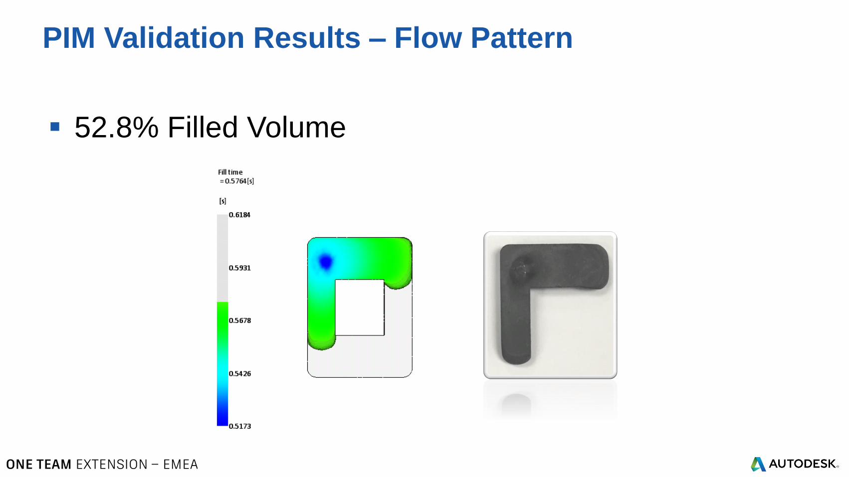
52.8% Filled Volume
PIM Validation Results – Flow Pattern
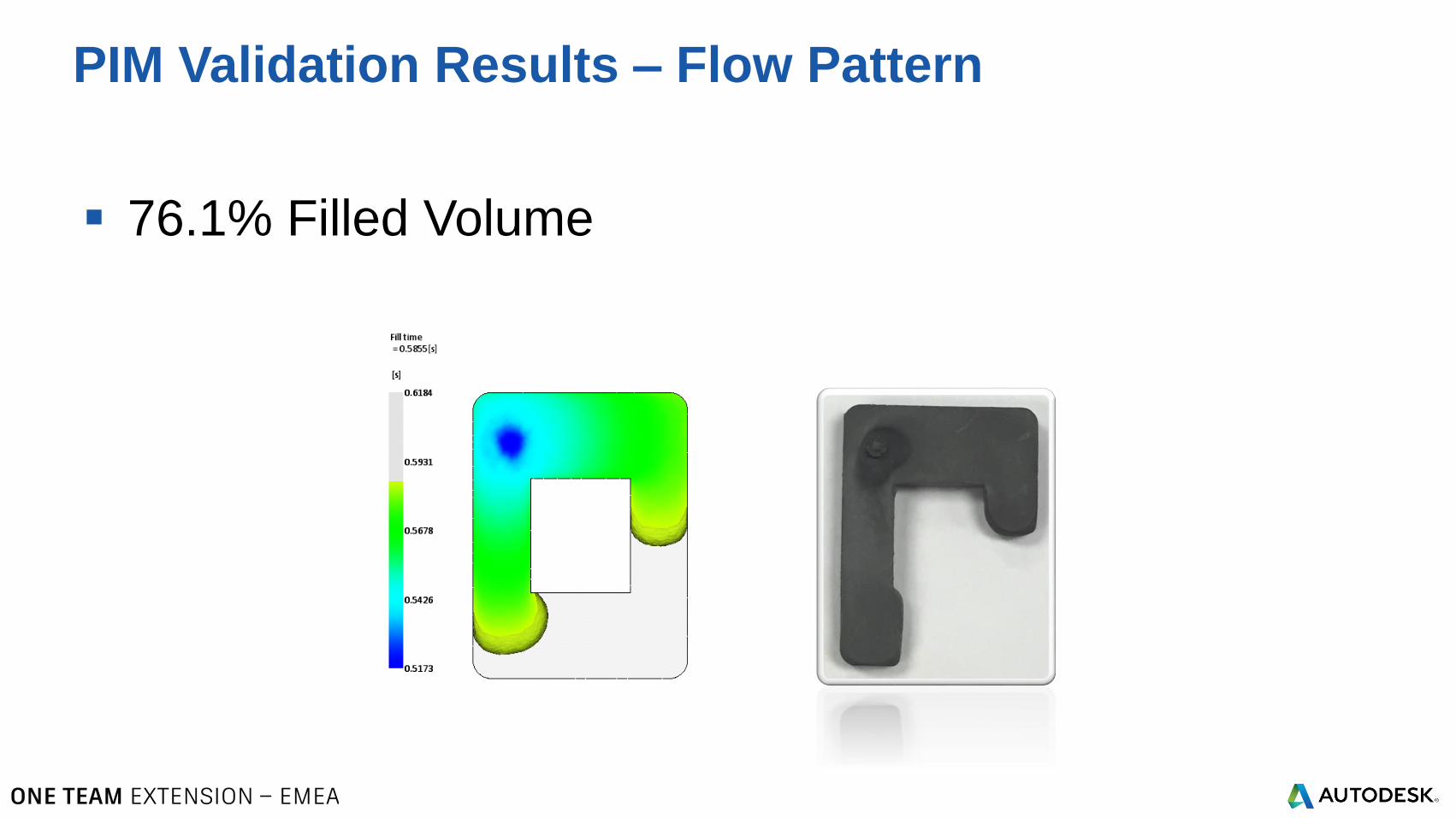
76.1% Filled Volume
PIM Validation Results – Flow Pattern
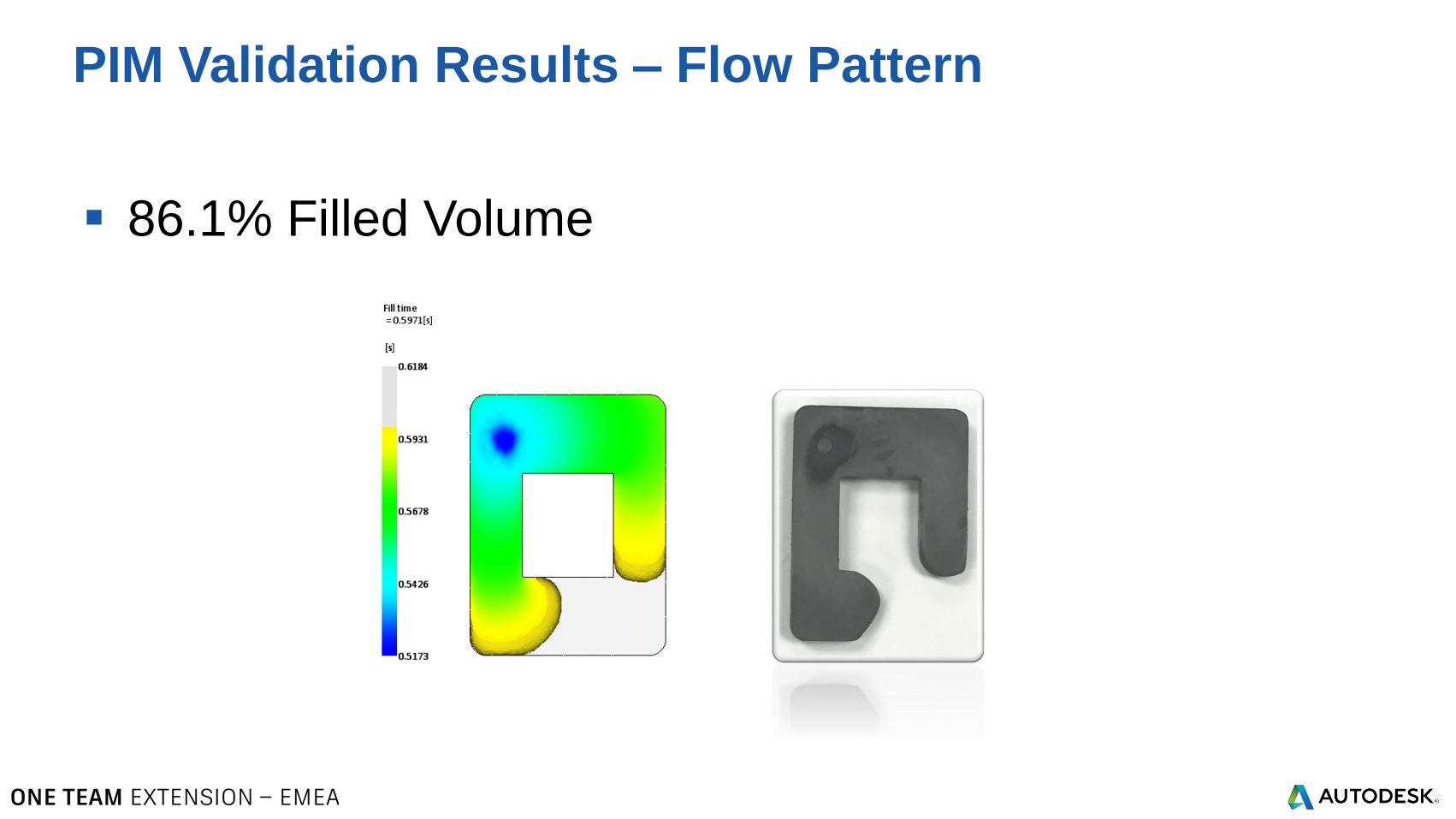
86.1% Filled Volume
PIM Validation Results – Flow Pattern
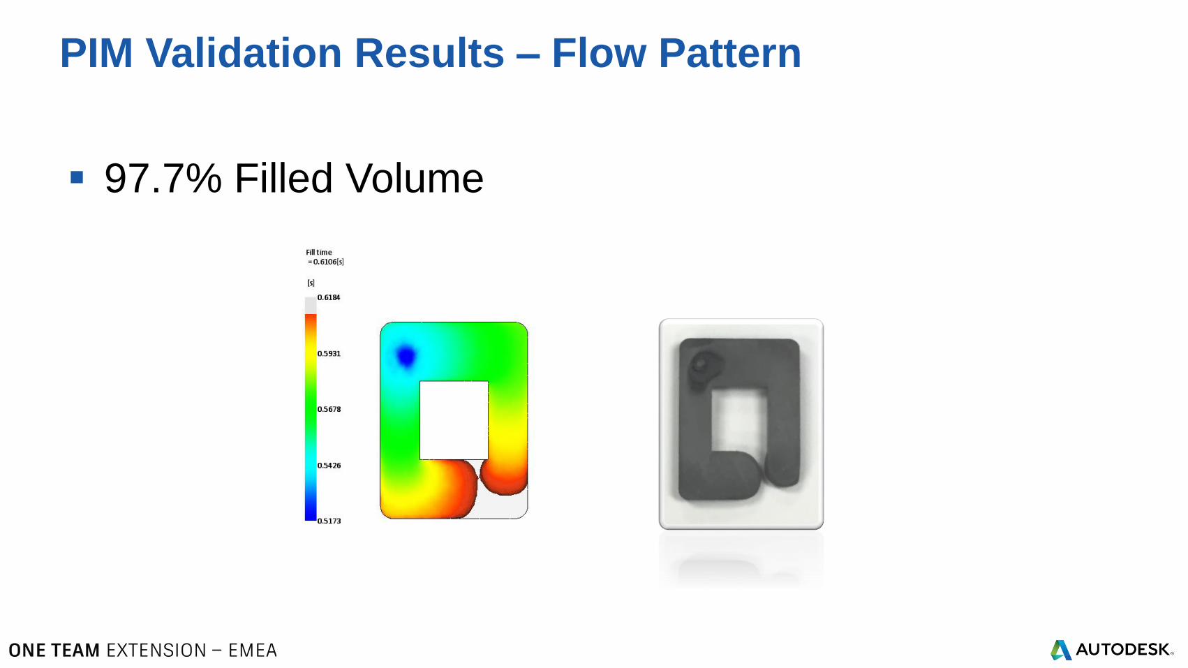
97.7% Filled Volume
PIM Validation Results – Flow Pattern
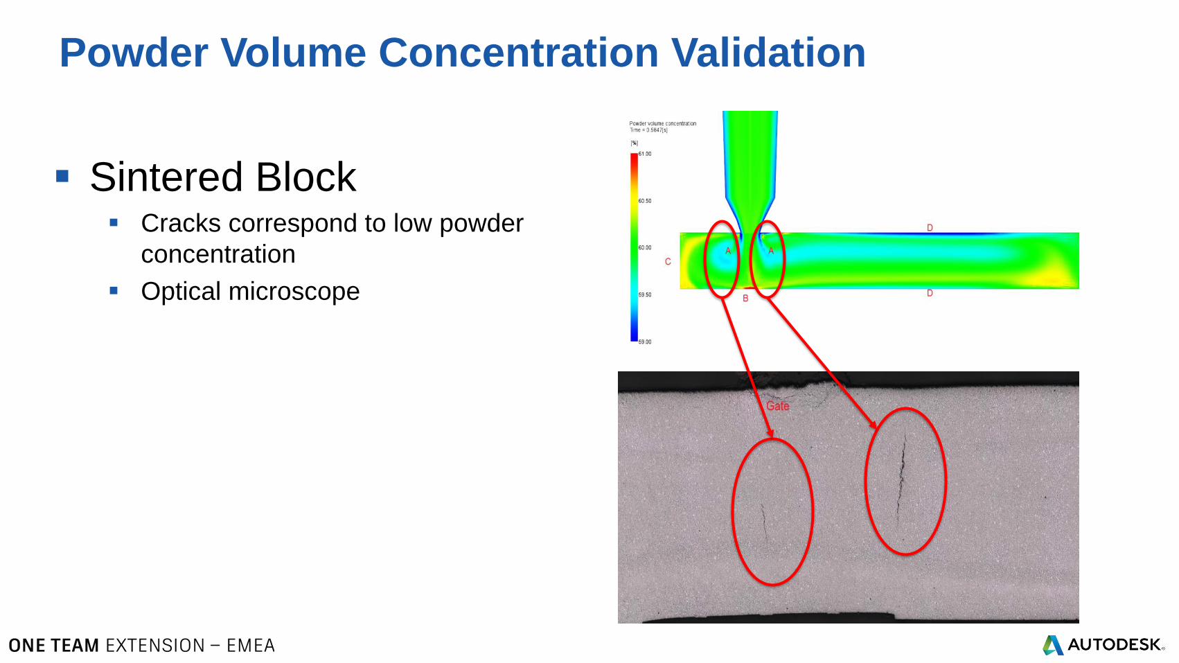
Sintered Block Cracks correspond to low powder
concentration
Optical microscope
Powder Volume Concentration Validation
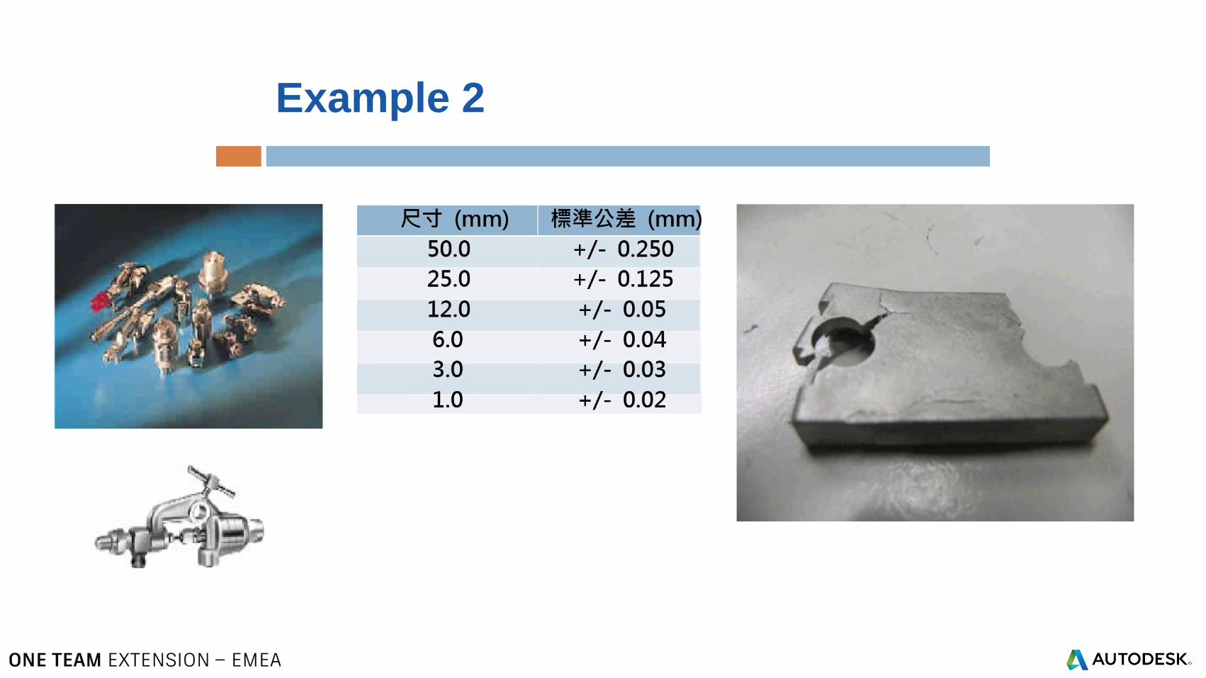
Example 2
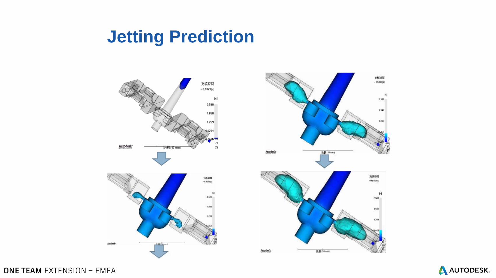
Jetting Prediction
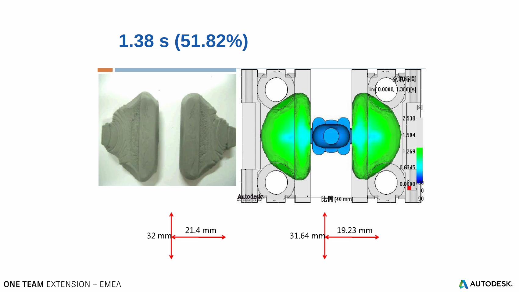
1.38 s (51.82%)
21.4 mm32 mm
19.23 mm31.64 mm
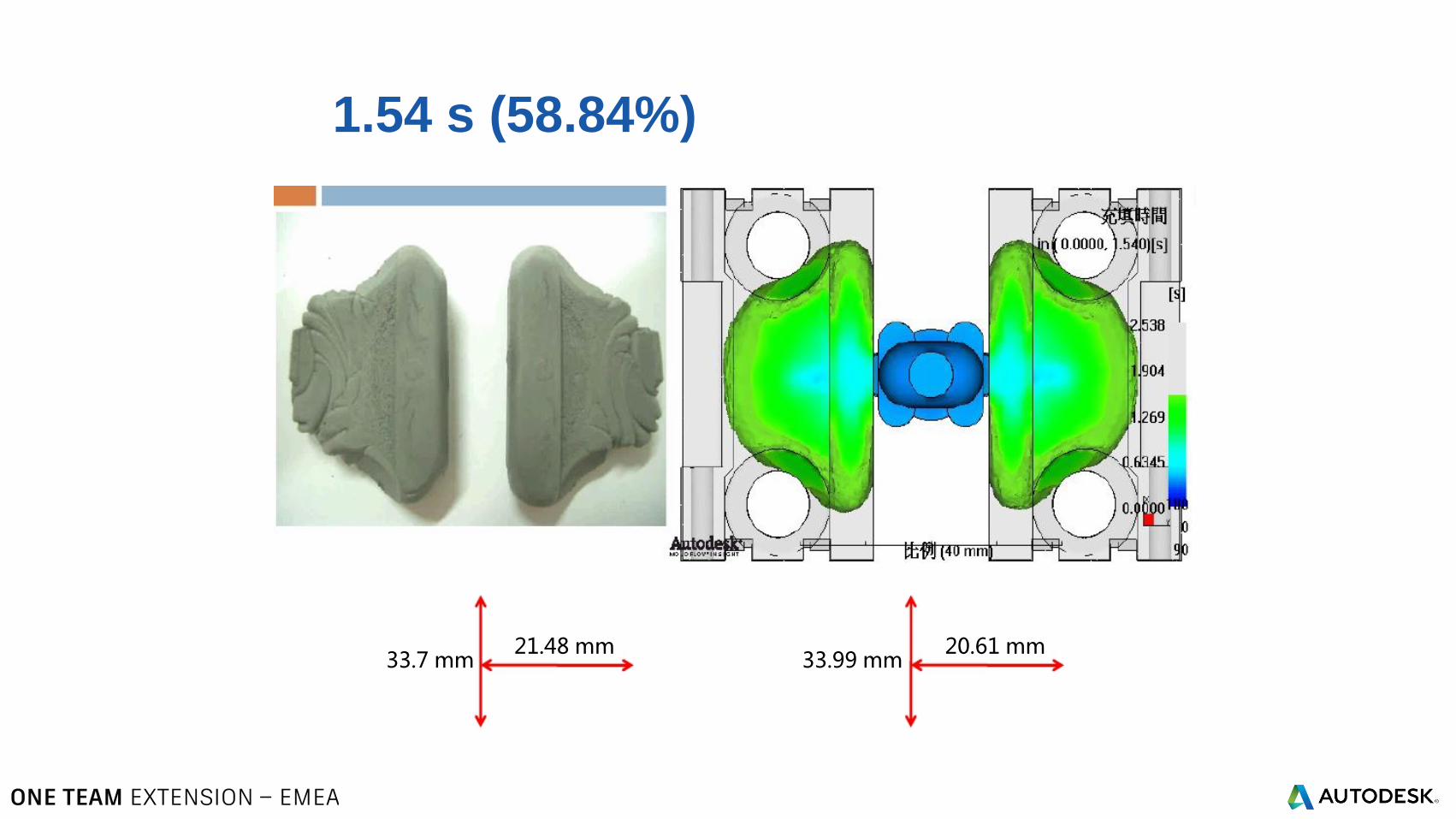
1.54 s (58.84%)
21.48 mm33.7 mm
20.61 mm33.99 mm
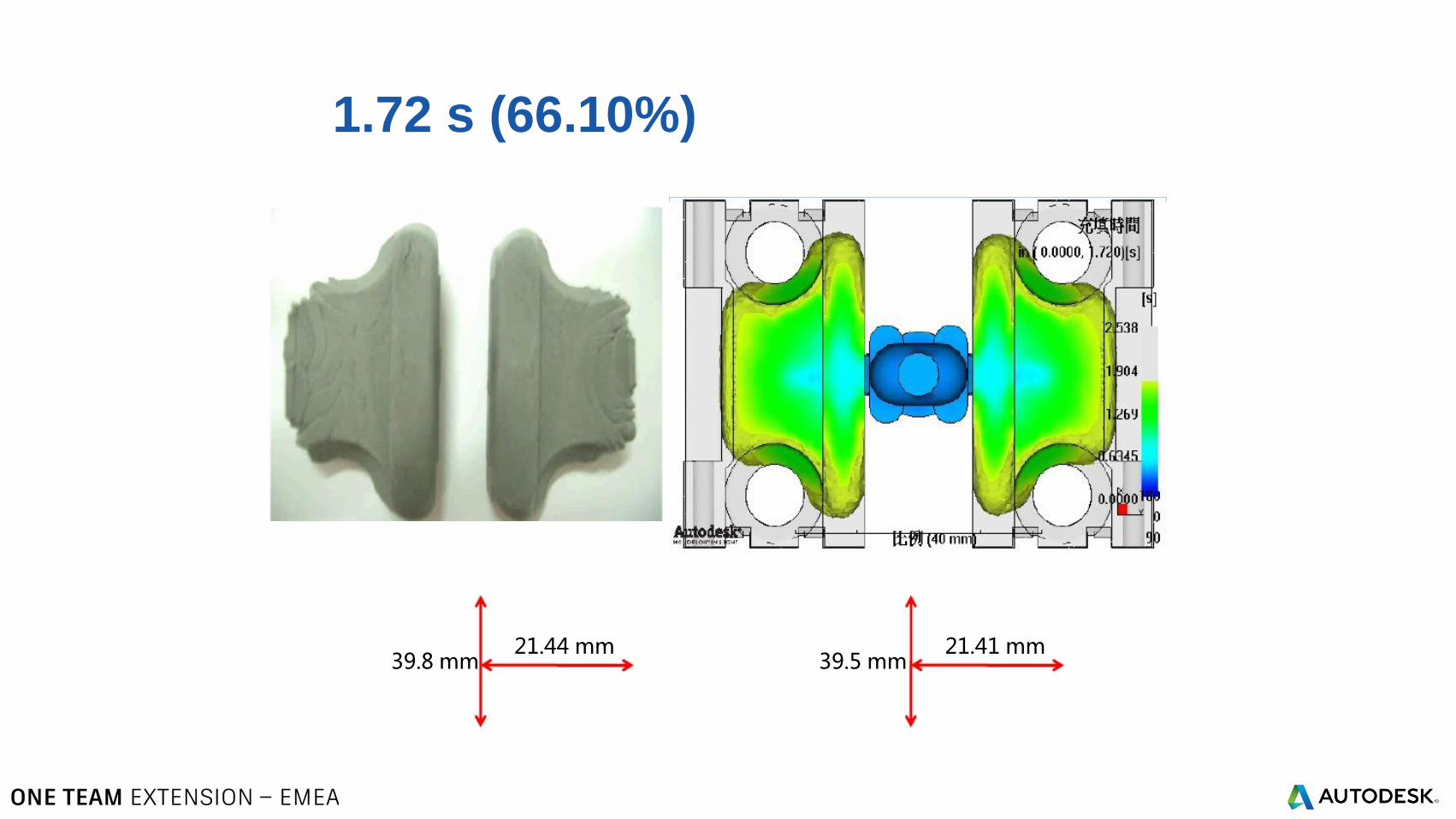
1.72 s (66.10%)
21.44 mm39.8 mm
21.41 mm39.5 mm
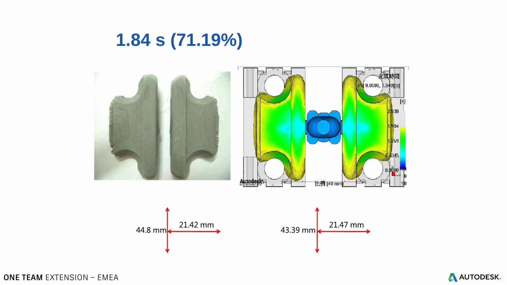
1.84 s (71.19%)
21.42 mm44.8 mm
21.47 mm43.39 mm
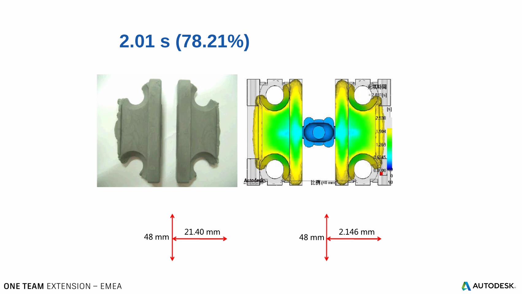
2.01 s (78.21%)
21.40 mm48 mm
2.146 mm48 mm
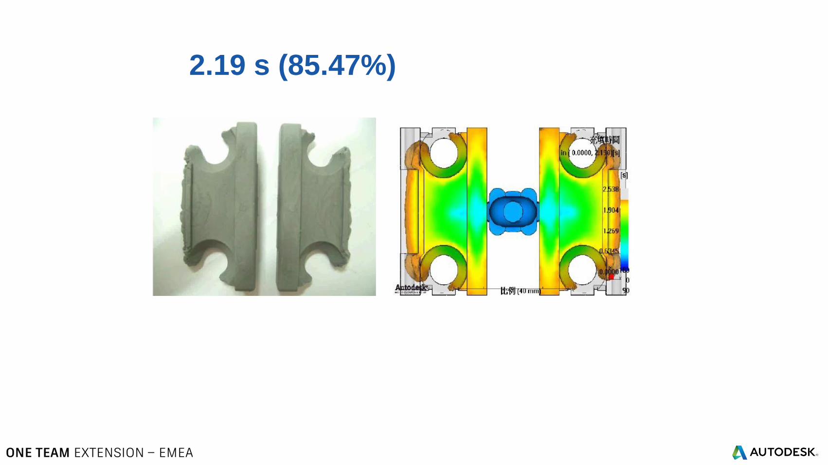
2.19 s (85.47%)
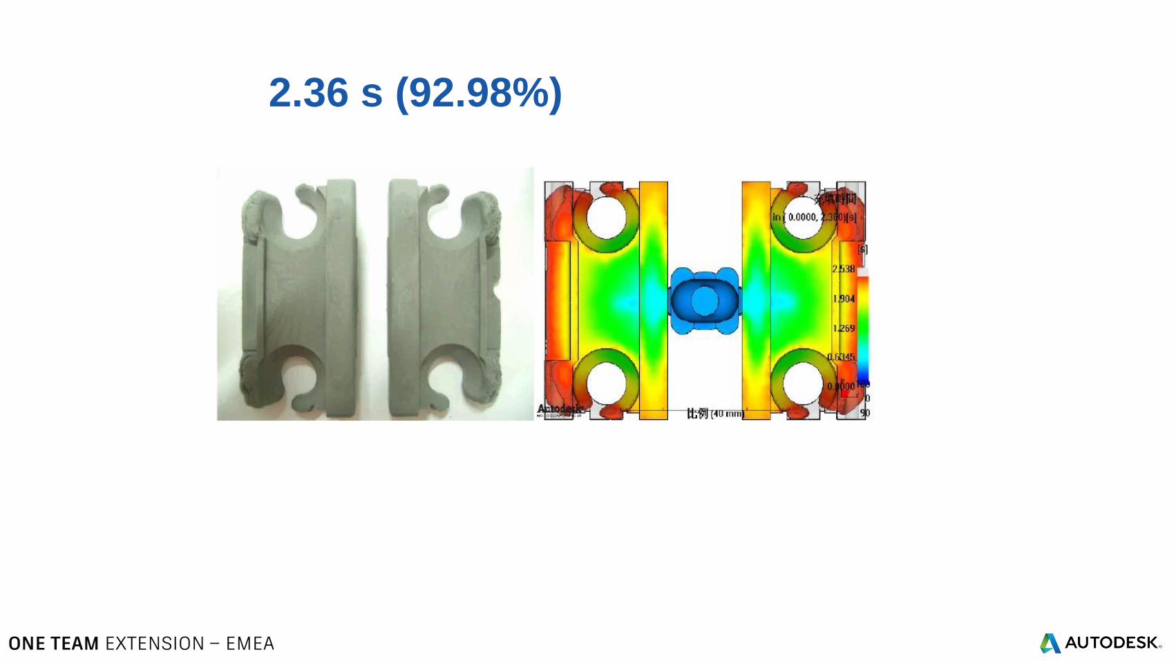
2.36 s (92.98%)
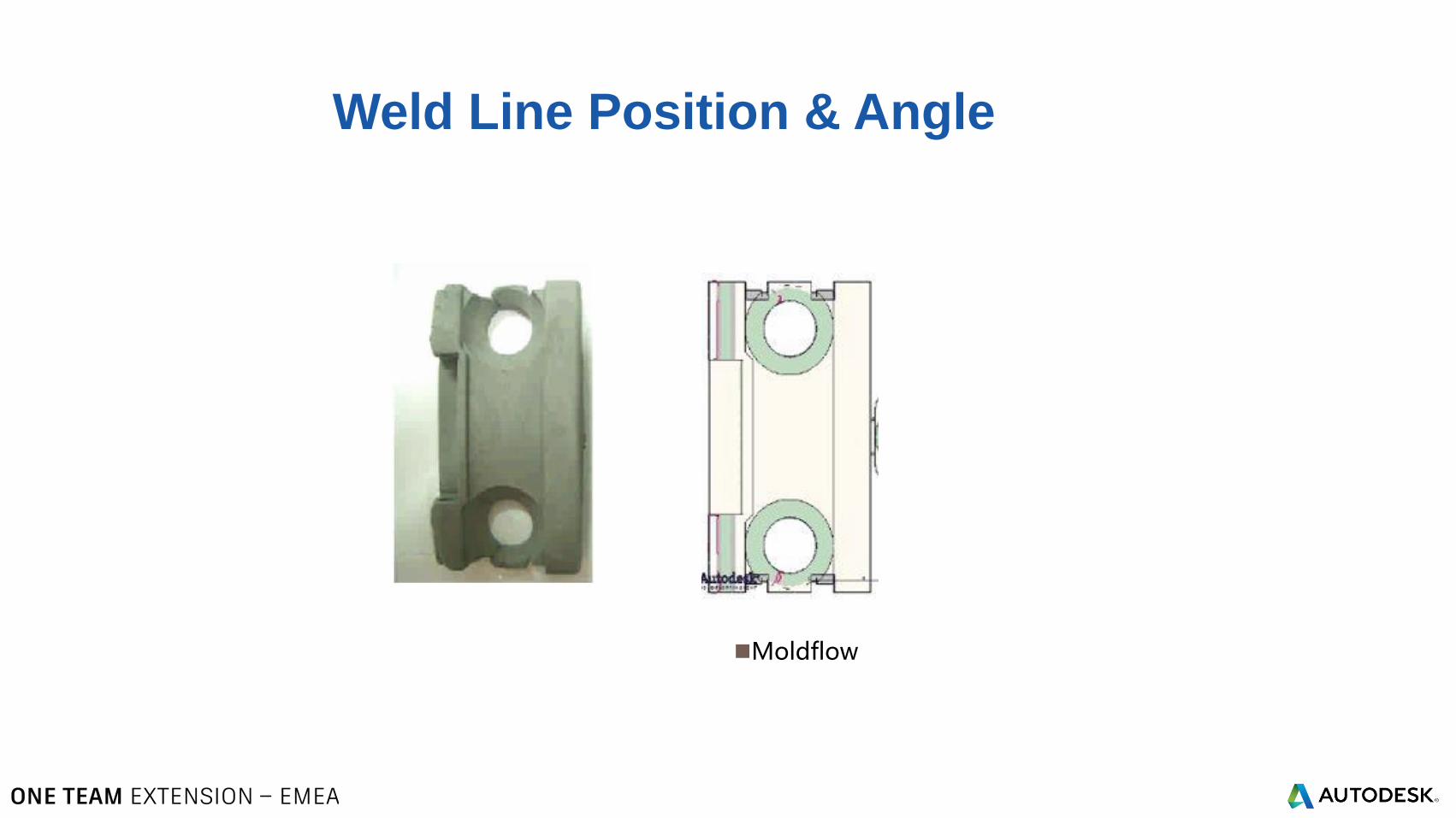
Weld Line Position & Angle
Moldflow
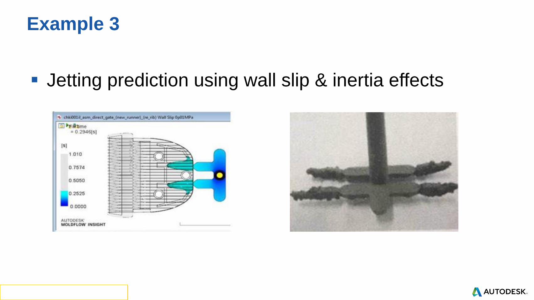
Jetting prediction using wall slip & inertia effects
Example 3