Embed Size (px)
Citation preview
Tutorials
Autodesk® MotionBuilder
® 2012
© 2011 Autodesk, Inc. All rights reserved. Except as otherwise permitted by Autodesk, Inc., this publication, or parts thereof, may notbe reproduced in any form, by any method, for any purpose.Certain materials included in this publication are reprinted with the permission of the copyright holder.The following are registered trademarks or trademarks of Autodesk, Inc., and/or its subsidiaries and/or affiliates in the USA and other countries:3DEC (design/logo), 3December, 3December.com, 3ds Max, Algor, Alias, Alias (swirl design/logo), AliasStudio, Alias|Wavefront (design/logo),ATC, AUGI, AutoCAD, AutoCAD Learning Assistance, AutoCAD LT, AutoCAD Simulator, AutoCAD SQL Extension, AutoCAD SQL Interface,Autodesk, Autodesk Intent, Autodesk Inventor, Autodesk MapGuide, Autodesk Streamline, AutoLISP, AutoSnap, AutoSketch, AutoTrack, Backburner,Backdraft, Beast, Built with ObjectARX (logo), Burn, Buzzsaw, CAiCE, Civil 3D, Cleaner, Cleaner Central, ClearScale, Colour Warper, Combustion,Communication Specification, Constructware, Content Explorer, Dancing Baby (image), DesignCenter, Design Doctor, Designer's Toolkit,DesignKids, DesignProf, DesignServer, DesignStudio, Design Web Format, Discreet, DWF, DWG, DWG (logo), DWG Extreme, DWG TrueConvert,DWG TrueView, DXF, Ecotect, Exposure, Extending the Design Team, Face Robot, FBX, Fempro, Fire, Flame, Flare, Flint, FMDesktop, Freewheel,GDX Driver, Green Building Studio, Heads-up Design, Heidi, HumanIK, IDEA Server, i-drop, Illuminate Labs AB (design/logo), ImageModeler,iMOUT, Incinerator, Inferno, Inventor, Inventor LT, Kynapse, Kynogon, LandXplorer, LiquidLight, LiquidLight (design/logo), Lustre, MatchMover,Maya, Mechanical Desktop, Moldflow, Moldflow Plastics Advisers, MPI, Moldflow Plastics Insight, Moldflow Plastics Xpert, Moondust, MotionBuilder,Movimento, MPA, MPA (design/logo), MPX, MPX (design/logo), Mudbox, Multi-Master Editing, Navisworks, ObjectARX, ObjectDBX, Opticore,Pipeplus, PolarSnap, PortfolioWall, Powered with Autodesk Technology, Productstream, ProMaterials, RasterDWG, RealDWG, Real-time Roto,Recognize, Render Queue, Retimer, Reveal, Revit, RiverCAD, Robot, Showcase, Show Me, ShowMotion, SketchBook, Smoke, Softimage,Softimage|XSI (design/logo), Sparks, SteeringWheels, Stitcher, Stone, StormNET, StudioTools, ToolClip, Topobase, Toxik, TrustedDWG, U-Vis,ViewCube, Visual, Visual LISP, Volo, Vtour, WaterNetworks, Wire, Wiretap, WiretapCentral, XSI.ACE™, TAO™, CIAO™, and CoSMIC™ are copyrighted by Douglas C. Schmidt and his research group at Washington University, University ofCalifornia, Irvine, and Vanderbilt University, Copyright (c) 1993-2009, all rights reserved.mental ray is a registered trademark of mental images GmbH licensed for use by Autodesk, Inc.Intel is a registered trademark or trademark of Intel Corporation or its subsidiaries in the United States and other countries.Python and the Python logo are trademarks or registered trademarks of the Python Software Foundation.All other brand names, product names or trademarks belong to their respective holders.
DisclaimerTHIS PUBLICATION AND THE INFORMATION CONTAINED HEREIN IS MADE AVAILABLE BY AUTODESK, INC. "AS IS." AUTODESK, INC. DISCLAIMSALL WARRANTIES, EITHER EXPRESS OR IMPLIED, INCLUDING BUT NOT LIMITED TO ANY IMPLIED WARRANTIES OF MERCHANTABILITY ORFITNESS FOR A PARTICULAR PURPOSE REGARDING THESE MATERIALS.
Contents
Chapter 1 Tutorials . . . . . . . . . . . . . . . . . . . . . . . . . . . . . . . 1Introduction . . . . . . . . . . . . . . . . . . . . . . . . . . . . . . . . 1MotionBuilder workflow . . . . . . . . . . . . . . . . . . . . . . . . . . 2Loading and Characterizing Character Models . . . . . . . . . . . . . . 7
Prepare the scene . . . . . . . . . . . . . . . . . . . . . . . . . . . 7Complete the character map . . . . . . . . . . . . . . . . . . . . . 9Characterize the character model . . . . . . . . . . . . . . . . . . 14
Creating and Customizing a Control Rig . . . . . . . . . . . . . . . . . 17Prepare the scene . . . . . . . . . . . . . . . . . . . . . . . . . . 17Create a Control rig . . . . . . . . . . . . . . . . . . . . . . . . . 18Adjust the foot floor contact markers . . . . . . . . . . . . . . . . 20Adjust the hand floor contact markers . . . . . . . . . . . . . . . 23Add Auxiliary pivots . . . . . . . . . . . . . . . . . . . . . . . . 24
Creating a Character Extension . . . . . . . . . . . . . . . . . . . . . . 28Prepare the scene . . . . . . . . . . . . . . . . . . . . . . . . . . 28Connect the extra limb to the character . . . . . . . . . . . . . . 30Create a Character Extension . . . . . . . . . . . . . . . . . . . . 34
Creating a Walk Cycle . . . . . . . . . . . . . . . . . . . . . . . . . . . 38Prepare the scene . . . . . . . . . . . . . . . . . . . . . . . . . . 39Create poses . . . . . . . . . . . . . . . . . . . . . . . . . . . . . 41Create animation with poses . . . . . . . . . . . . . . . . . . . . 49Mirror poses . . . . . . . . . . . . . . . . . . . . . . . . . . . . . 53Play the animation . . . . . . . . . . . . . . . . . . . . . . . . . 55
Retargeting Character Animation . . . . . . . . . . . . . . . . . . . . . 56
iii
Prepare the scene . . . . . . . . . . . . . . . . . . . . . . . . . . 56Save the character animation . . . . . . . . . . . . . . . . . . . . 58Create a scene . . . . . . . . . . . . . . . . . . . . . . . . . . . . 59Load character animation . . . . . . . . . . . . . . . . . . . . . . 61Play the animation . . . . . . . . . . . . . . . . . . . . . . . . . 65
Editing Character Animation . . . . . . . . . . . . . . . . . . . . . . . 66Prepare the scene . . . . . . . . . . . . . . . . . . . . . . . . . . 66Modify the Character Extension animation . . . . . . . . . . . . 68Modify the head animation . . . . . . . . . . . . . . . . . . . . . 73Play the resulting take . . . . . . . . . . . . . . . . . . . . . . . . 76
Creating a Loop . . . . . . . . . . . . . . . . . . . . . . . . . . . . . . 76Prepare the scene . . . . . . . . . . . . . . . . . . . . . . . . . . 77Create a Character track . . . . . . . . . . . . . . . . . . . . . . . 78Create poses . . . . . . . . . . . . . . . . . . . . . . . . . . . . . 82Match clips . . . . . . . . . . . . . . . . . . . . . . . . . . . . . 85Process the clips . . . . . . . . . . . . . . . . . . . . . . . . . . . 87Test the walk cycle . . . . . . . . . . . . . . . . . . . . . . . . . 89
Manipulating Clips . . . . . . . . . . . . . . . . . . . . . . . . . . . . 90Prepare the scene . . . . . . . . . . . . . . . . . . . . . . . . . . 91Create a turn . . . . . . . . . . . . . . . . . . . . . . . . . . . . 92Blend two clips . . . . . . . . . . . . . . . . . . . . . . . . . . . 96Add a clip . . . . . . . . . . . . . . . . . . . . . . . . . . . . . . 97Match clips . . . . . . . . . . . . . . . . . . . . . . . . . . . . . 98
Importing 3ds Max Files into MotionBuilder . . . . . . . . . . . . . . 100Prepare for this tutorial . . . . . . . . . . . . . . . . . . . . . . 1013ds Max skeletons . . . . . . . . . . . . . . . . . . . . . . . . . 102
Export and characterize a 3ds Max skeleton inMotionBuilder . . . . . . . . . . . . . . . . . . . . . . . 102
3ds Max Bipeds . . . . . . . . . . . . . . . . . . . . . . . . . . 112Create and export a 3ds Max biped . . . . . . . . . . . . . 112Characterize a 3ds Max biped in MotionBuilder . . . . . . 116
3ds Max Characters . . . . . . . . . . . . . . . . . . . . . . . . 125Export a 3ds Max character . . . . . . . . . . . . . . . . . 125Import and characterize a 3ds Max Character in
MotionBuilder . . . . . . . . . . . . . . . . . . . . . . . 130Animating a 3ds Max Character in MotionBuilder . . . . . . . . 135
Animate a character using motion capture data . . . . . . 136Modify character animation with keyframes and export
it to 3ds Max . . . . . . . . . . . . . . . . . . . . . . . . 141
iv | Contents
Tutorials
IntroductionThis chapter includes a set of nine Autodesk MotionBuilder tutorials that providea common MotionBuilder workflow and demonstrate how to use the morepowerful keyframe and character animation features.
NOTE This suite of tutorials assumes that you are using Autodesk MotionBuilder2012. Some tutorials in this suite of tutorials use the 2012 Single-step interoperabilityfeatures, such as the "Send to" functionality included with 3ds Max and Maya 2012.
If you do not have 2012 version of the 3ds Max software, refer to the legacyworkflows covered in the MotionBuilder Help to perform these takes. A noteaccompanies these tutorials that will direct you to procedures for the legacyworkflow in the MotionBuilder documentation.
You can find the tutorial assets in the MotionBuilder Asset browser’s Tutorialsfolder as well as in the Tutorials folder located in the MotionBuilder directoryon your system.
NOTE The tutorials use the Editing layout (Layout > Editing) for these tasks but ifany window is unavailable, you can select it from the MotionBuilder menu bar >Window menu. If the Tutorials folder is not displayed in the Asset browser, you needto add a favorite path to display a directory in the Asset Browser.
To add a directory to be displayed in the Asset browser:
■ See Adding a favorite path.
NOTE You can download the tutorial assets (or support files) from:http://www.autodesk.com/motionbuilder2012-documentation.
1
1
See also:
MotionBuilder workflow (page 2)
MotionBuilder workflowThis topic describes a common workflow that introduces the nine tutorialsprovided to help you become familiar with the MotionBuilder software product.Procedures in the tutorials that do not have dedicated tutorials are addressedin the MotionBuilder Help.
Although these tutorials assume you are using MotionBuilder for a characteranimation project, this workflow can be easily adapted to any animationproject where MotionBuilder is used in conjunction with other 3D modelingor rendering software.
There are two basic workflows for using MotionBuilder:
■ Autodesk Interoperability workflow
■ Generic workflow
Use the Autodesk Interoperability workflow when you are using Autodesk2012 software which makes use of streamlined interoperability workflows.Use the Generic Workflow when you are using pre-2012 versions of 3ds Maxand Maya, or are using another 3ds software package that exports to AutodeskFBX format.
Autodesk interoperability workflow
Maya and 3ds Max 2012 both have single-step interoperability features thatbring your model into MotionBuilder automatically. If you do not have the2012 versions of these packages, see the Generic workflow, below.
1 Create a character model in your Maya or 3ds Max 2012software.
Before you start your animation project using MotionBuilder, there area few things you can do when modeling to facilitate your work inMotionBuilder.
Refer to Guidelines for creating a character model, Bone namingconventions, Import and characterize a 3ds Max biped in MotionBuilder(page 116), and Choosing shapes to create.
2 | Chapter 1 Tutorials
2 Export the character model from Maya or 3ds Max by selectingSend to MotionBuilder from the File menu.
If MotionBuilder 2012 is installed, it launches and loads your charactermodel.
3 Once the model loads into MotionBuilder, set it up foranimation by dragging the 3ds Max or MotionBuilderCharacter asset on top of it.
The Character asset helps you map the structure of your character modelso that it can be animated in MotionBuilder. Once you complete thismapping process, you ‘activate’ the character model by characterizingit. Characterizing lets MotionBuilder know that this character model isready to be animated. The first tutorial shows you how to importcharacter models into MotionBuilder and prepare them for animation.
See Loading and characterizing character models (page 14).
4 Add a Control rig and customize it to fit your characteranimation needs.
Control rigs are an animation tool that make it easy to control andposition your character model.
The second tutorial shows you how to customize a Control rig and addcharacter animation features such as floor contacts and Auxiliary pivots.
See Creating and Customizing a Control Rig (page 17).
5 Add Character Extensions to support props or non-humanbody parts.
The third tutorial shows you how to augment your character with anextra limb, in this case a “Servo arm” with giant pincers attached to thecharacter’s right shoulder.
See Creating a Character Extension (page 28).
6 Create your animation using different keyframing andcharacter animation features.■ One efficient method of creating animation involves creating a set
of poses that can be pasted onto your character at various points overtime.
The fourth tutorial shows you how to use the Control rig and thePose Controls to create a walk cycle.
See Creating a Walk Cycle (page 38).
■ The seventh tutorial shows you an alternative method for creating awalk cycle using clips in the Story window.
See Creating a Loop (page 76).
MotionBuilder workflow | 3
7 Edit and refine your animation.■ The sixth tutorial shows you how to use layers to edit animation.
See Editing Character Animation (page 66).
■ The eighth tutorial shows you how to combine animations using theStory window.
See Manipulating Clips (page 90).
8 Retarget your animation between Character models.
During animation projects, the Character model you use might change.Although not a required step for creating animation withinMotionBuilder, instead of re-creating the animation on a new model,you can simply apply the same animation to the desired model(s).
The fifth tutorial shows you how to transfer animation and CharacterExtensions between character models.
See Retargeting Character Animation (page 56).
9 If you want to animate 3ds Max characters in MotionBuilder,and then use that animation in 3ds Max, you need to importyour 3ds Max scene into MotionBuilder, animate inMotionBuilder, then import your animation in 3ds Max.
This last tutorial shows you the major steps for importing animationinto MotionBuilder, animating in MotionBuilder, and exporting theanimation from MotionBuilder and importing it to 3ds Max.
See the following major sections: 3ds Max skeletons (page 102), 3ds MaxBipeds (page 112), 3ds Max Characters (page 125), and Animating 3ds MaxCharacters in MotionBuilder (page 135).
Generic workflow
Maya and 3ds Max 2012 both have one-step interoperability features thatbrings your model into MotionBuilder automatically. If you do not have the2012 versions of these packages, you need to install the appropriate Maya or3ds Max FBX Plug-in to transfer your models into MotionBuilder. Downloadthe free FBX plug-in here.
If you are using another 3D software package, you can convert your file toFBX using the free FBX Converter that you can download from here.
1 Create a character model in your 3D software.
Before you start your animation project using MotionBuilder, there area few things you can do when modeling to facilitate your work inMotionBuilder.
4 | Chapter 1 Tutorials
Refer to Guidelines for creating a character model, Bone namingconventions, Import and characterize a 3ds Max biped in MotionBuilder(page 116), and Choosing shapes to create.
2 Export the character model from your modeling softwarepackage.
When you export your work from a modeling software package, the FBXPlug-in you installed lets you save your character model in the .fbx fileformat. This format enables you to load your models in MotionBuilder.
3 Start MotionBuilder and load your character model.
Once you load a model into MotionBuilder, you can set it up to animateit using the MotionBuilder Character asset.
4 Once the model loads into MotionBuilder, set it up foranimation by dragging the 3ds Max or MotionBuilderCharacter asset on top of it.
The Character asset helps you map the structure of your character modelso that it can be animated in MotionBuilder. Once you complete thismapping process, you ‘activate’ the character model by characterizingit. Characterizing lets MotionBuilder know that this character model isready to be animated.
5 Add a Character asset to your character model and characterizeit.
The Character asset helps you map the structure of your character modelso that it can be animated in MotionBuilder. Once you complete thismapping process, you ‘activate’ the character model by characterizingit. Characterizing lets MotionBuilder know that this character model isready to be animated. All major character animation features inMotionBuilder, including Control rigs and animating in the Storywindow, require a characterized character.
The first tutorial shows you how to create a Character asset and use itto map out your character model’s structure.
See Loading and Characterizing Character Models (page 7).
6 Add a Control rig and customize it to fit your characteranimation needs.
Control rigs are an animation tool that make it easy to control andposition your character model.
The second tutorial shows you how to customize a Control rig and addcharacter animation features such as floor contacts and Auxiliary pivots.
See Creating and Customizing a Control Rig (page 17).
MotionBuilder workflow | 5
7 Add Character Extensions to support props or non-humanbody parts.
The third tutorial shows you how to augment your character with anextra limb, in this case a “Servo arm” with giant pincers attached to thecharacter’s right shoulder.
See Creating a Character Extension (page 28).
8 Create your animation using different keyframing andcharacter animation features.■ One efficient method of creating animation involves creating a set
of poses that can be pasted onto your character at various points overtime.
The fourth tutorial shows you how to use the Control rig and thePose Controls to create a walk cycle.
See Creating a Walk Cycle (page 38).
■ The seventh tutorial shows you an alternative method for creating awalk cycle using clips in the Story window.
See Creating a Loop (page 76).
9 Edit and refine your animation.■ The sixth tutorial shows you how to use layers to edit animation.
See Editing Character Animation (page 66).
■ The eighth tutorial shows you how to combine animations using theStory window.
See Manipulating Clips (page 90).
10 Retarget your animation between Character models.
During animation projects, the Character model you use might change.Although not a required step for creating animation withinMotionBuilder, instead of re-creating the animation on a new model,you can simply apply the same animation to the desired model(s).
The fifth tutorial shows you how to transfer animation and CharacterExtensions between character models.
See Retargeting Character Animation (page 56).
11 Plot your finished animation to your model’s skeleton.
Depending on the animation features you are using to create yourcharacter animation, plotting may consist of plotting from your Controlrig to your character model skeleton, or plotting the tracks in the Storywindow to a single take.
6 | Chapter 1 Tutorials
Whatever method you use to animate, the finished result must be plottedto the skeleton of your character model before you export it.
See The plotting process.
12 Save your plotted model as an .fbx file.
Your finished animations can also be exported for rendering in thesoftware of your choice using the appropriate FBX Plug-In.
You can download the latest FBX Plug-ins from:http://www.autodesk.com/fbx.
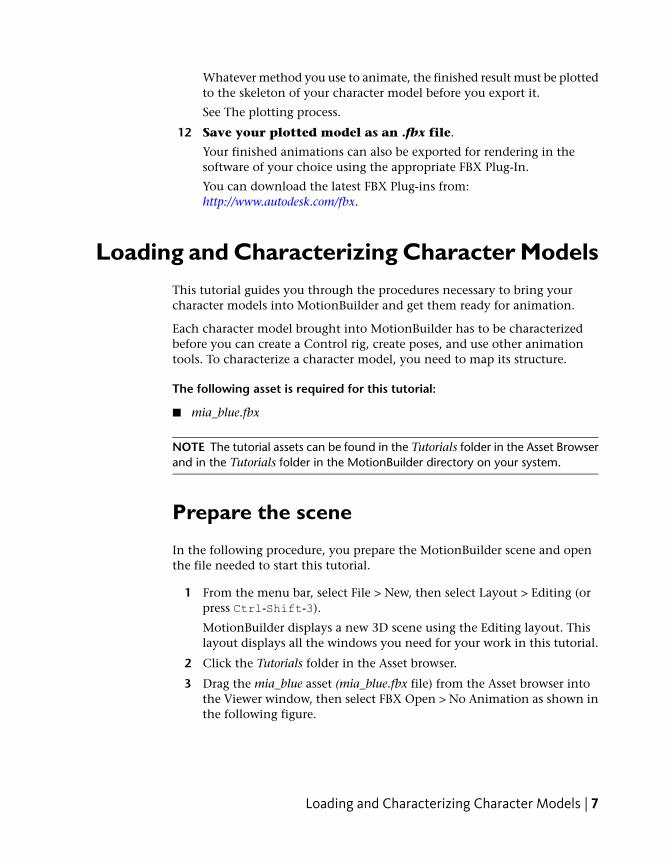
Loading and Characterizing Character ModelsThis tutorial guides you through the procedures necessary to bring yourcharacter models into MotionBuilder and get them ready for animation.
Each character model brought into MotionBuilder has to be characterizedbefore you can create a Control rig, create poses, and use other animationtools. To characterize a character model, you need to map its structure.
The following asset is required for this tutorial:
■ mia_blue.fbx
NOTE The tutorial assets can be found in the Tutorials folder in the Asset Browserand in the Tutorials folder in the MotionBuilder directory on your system.
Prepare the scene
In the following procedure, you prepare the MotionBuilder scene and openthe file needed to start this tutorial.
1 From the menu bar, select File > New, then select Layout > Editing (orpress Ctrl-Shift-3).
MotionBuilder displays a new 3D scene using the Editing layout. Thislayout displays all the windows you need for your work in this tutorial.
2 Click the Tutorials folder in the Asset browser.
3 Drag the mia_blue asset (mia_blue.fbx file) from the Asset browser intothe Viewer window, then select FBX Open > No Animation as shown inthe following figure.
Loading and Characterizing Character Models | 7
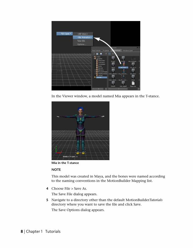
In the Viewer window, a model named Mia appears in the T-stance.
Mia in the T-stance
NOTE
This model was created in Maya, and the bones were named accordingto the naming conventions in the MotionBuilder Mapping list.
4 Choose File > Save As.
The Save File dialog appears.
5 Navigate to a directory other than the default MotionBuilderTutorialsdirectory where you want to save the file and click Save.
The Save Options dialog appears.
8 | Chapter 1 Tutorials
6 Click Save.
Choosing to save the file to a directory other than the defaultMotionBuilderTutorials directory ensures you do not overwrite theoriginal .fbx file.
Complete the character map
In the following procedure, you define the structure of your character modelfor MotionBuilder by mapping the required nodes in the Mapping list.Character mapping describes the character model for MotionBuilder, indicatingwhat are the legs, arms, and so on.
Although you can automatically map and characterize a character by draggingthe Character asset directly onto a character model, for the purpose of thistutorial, you manually map out Mia’s structure.
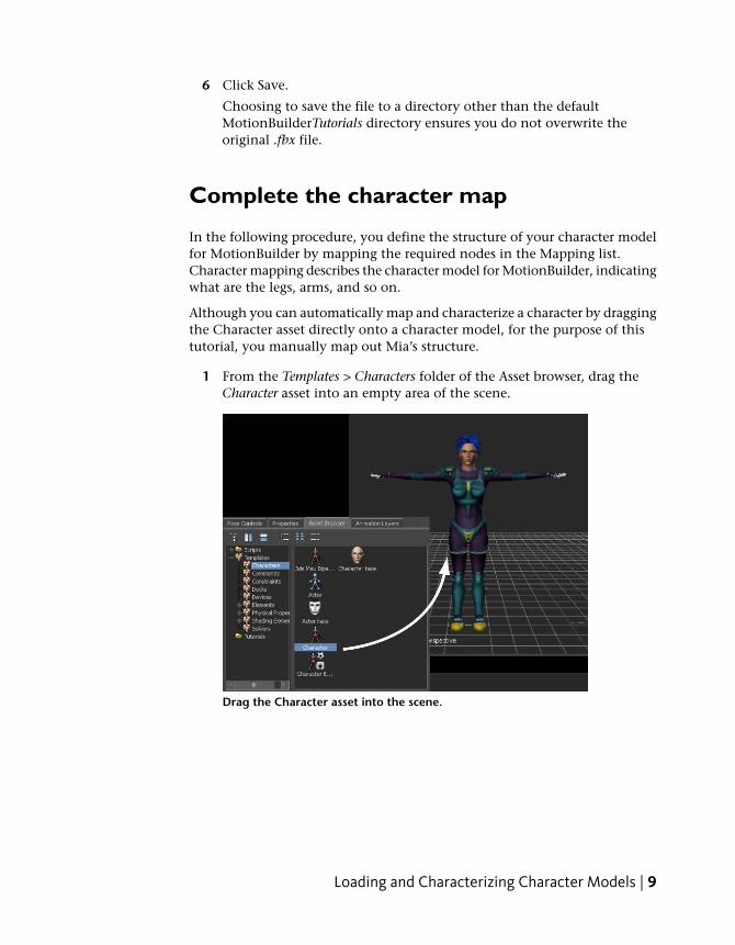
1 From the Templates > Characters folder of the Asset browser, drag theCharacter asset into an empty area of the scene.
Drag the Character asset into the scene.
Loading and Characterizing Character Models | 9
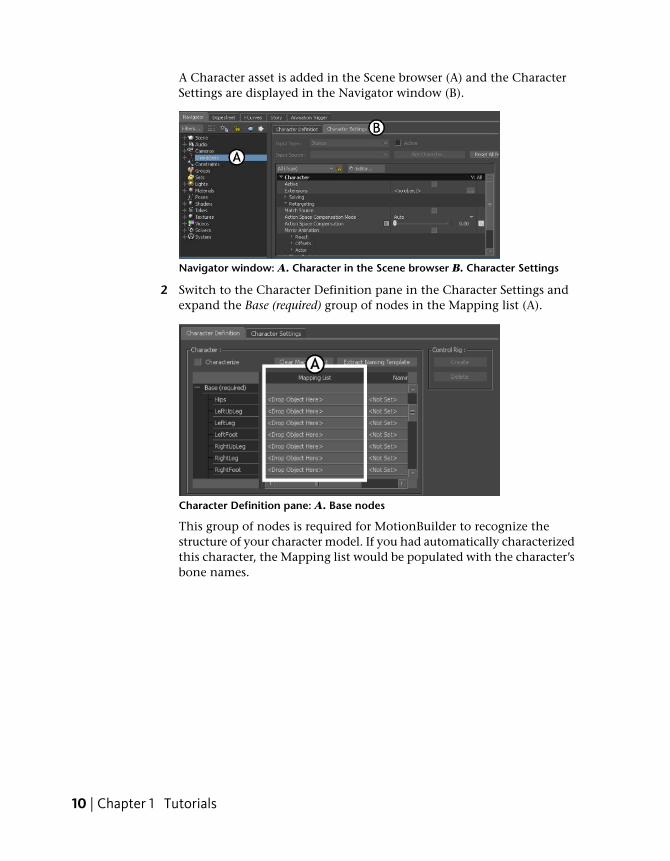
A Character asset is added in the Scene browser (A) and the CharacterSettings are displayed in the Navigator window (B).
Navigator window: A. Character in the Scene browser B. Character Settings
2 Switch to the Character Definition pane in the Character Settings andexpand the Base (required) group of nodes in the Mapping list (A).
Character Definition pane: A. Base nodes
This group of nodes is required for MotionBuilder to recognize thestructure of your character model. If you had automatically characterizedthis character, the Mapping list would be populated with the character’sbone names.
10 | Chapter 1 Tutorials
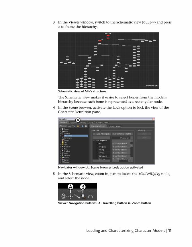
3 In the Viewer window, switch to the Schematic view (Ctrl-W) and pressA to frame the hierarchy.
Schematic view of Mia’s structure
The Schematic view makes it easier to select bones from the model’shierarchy because each bone is represented as a rectangular node.
4 In the Scene browser, activate the Lock option to lock the view of theCharacter Definition pane.
Navigator window: A. Scene browser Lock option activated
5 In the Schematic view, zoom in, pan to locate the Mia:LeftUpLeg node,and select the node.
Viewer Navigation buttons: A. Travelling button B. Zoom button
Loading and Characterizing Character Models | 11
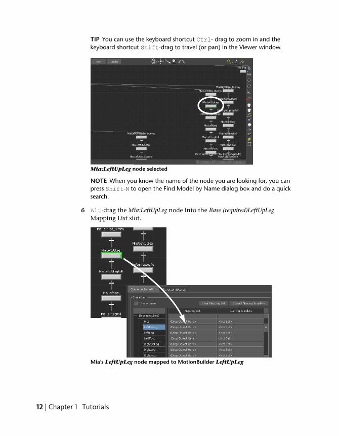
TIP You can use the keyboard shortcut Ctrl- drag to zoom in and thekeyboard shortcut Shift-drag to travel (or pan) in the Viewer window.
Mia:LeftUpLeg node selected
NOTE When you know the name of the node you are looking for, you canpress Shift-N to open the Find Model by Name dialog box and do a quicksearch.
6 Alt-drag the Mia:LeftUpLeg node into the Base (required)LeftUpLegMapping List slot.
Mia’s LeftUpLeg node mapped to MotionBuilder LeftUpLeg
12 | Chapter 1 Tutorials
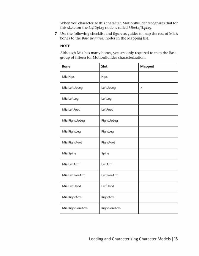
When you characterize this character, MotionBuilder recognizes that forthis skeleton the LeftUpLeg node is called Mia:LeftUpLeg.
7 Use the following checklist and figure as guides to map the rest of Mia’sbones to the Base (required) nodes in the Mapping list.
NOTE
Although Mia has many bones, you are only required to map the Basegroup of fifteen for MotionBuilder characterization.
MappedSlotBone
HipsMia:Hips
xLeftUpLegMia:LeftUpLeg
LeftLegMia:LeftLeg
LeftFootMia:LeftFoot
RightUpLegMia:RightUpLeg
RightLegMia:RightLeg
RightFootMia:RightFoot
SpineMia:Spine
LeftArmMia:LeftArm
LeftForeArmMia:LeftForeArm
LeftHandMia:LeftHand
RightArmMia:RightArm
RightForeArmMia:RightForeArm
Loading and Characterizing Character Models | 13
MappedSlotBone
RightHandMia:RightHand
HeadMia:Head
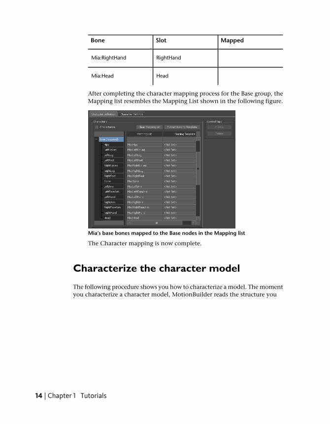
After completing the character mapping process for the Base group, theMapping list resembles the Mapping List shown in the following figure.
Mia’s base bones mapped to the Base nodes in the Mapping list
The Character mapping is now complete.
Characterize the character model
The following procedure shows you how to characterize a model. The momentyou characterize a character model, MotionBuilder reads the structure you
14 | Chapter 1 Tutorials
have outlined in the Mapping list, taking the model’s current pose as the basefor all future poses and movement.
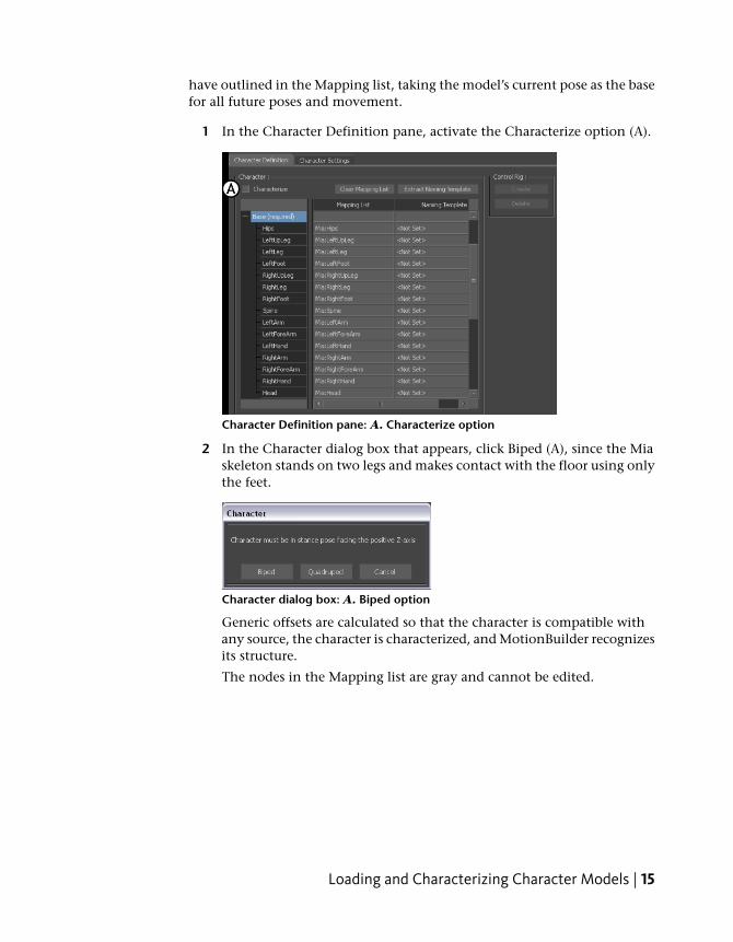
1 In the Character Definition pane, activate the Characterize option (A).
Character Definition pane: A. Characterize option
2 In the Character dialog box that appears, click Biped (A), since the Miaskeleton stands on two legs and makes contact with the floor using onlythe feet.
Character dialog box: A. Biped option
Generic offsets are calculated so that the character is compatible withany source, the character is characterized, and MotionBuilder recognizesits structure.
The nodes in the Mapping list are gray and cannot be edited.
Loading and Characterizing Character Models | 15
NOTE
If you want to add more bones or edit the Mapping list later, you cantemporarily disable the Characterize option when your character is inthe T-stance.
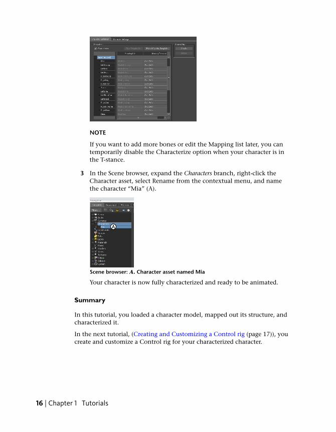
3 In the Scene browser, expand the Characters branch, right-click theCharacter asset, select Rename from the contextual menu, and namethe character “Mia” (A).
Scene browser: A. Character asset named Mia
Your character is now fully characterized and ready to be animated.
Summary
In this tutorial, you loaded a character model, mapped out its structure, andcharacterized it.
In the next tutorial, (Creating and Customizing a Control rig (page 17)), youcreate and customize a Control rig for your characterized character.
16 | Chapter 1 Tutorials
Creating and Customizing a Control RigThis tutorial guides you through the procedures necessary to create a Controlrig and customize the Control rig to create animation in subsequent tutorials.
Control rigs are an animation tool that make it easy to control and positionyour character model. You can re-purpose Control rigs for other models.
The following asset is required for this tutorial:
■ mia_characterized.fbx
NOTE The tutorial assets can be found in the Tutorials folder in the Asset Browserand in the Tutorials folder in the MotionBuilder directory on your system.
Prepare the scene
In the following procedure, you prepare the MotionBuilder scene and openthe file needed to start this tutorial.
1 From the menu bar, select File > New, then select Layout > Editing (orpress Ctrl-Shift-3).
MotionBuilder displays a new 3D scene using the Editing layout. Thislayout displays all the windows you need for your work in this tutorial.
2 Click the Tutorials folder in the Asset browser.
Creating and Customizing a Control Rig | 17
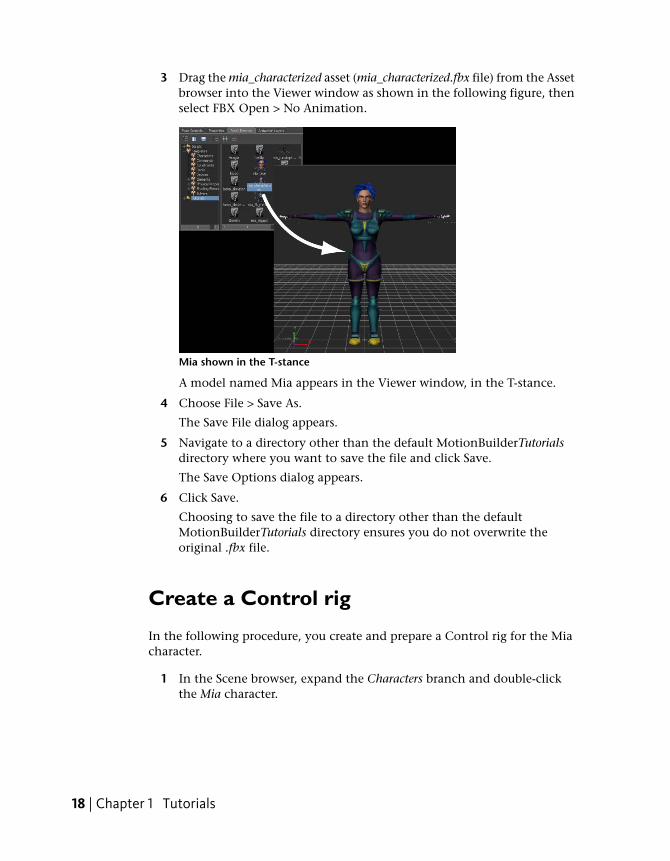
3 Drag the mia_characterized asset (mia_characterized.fbx file) from the Assetbrowser into the Viewer window as shown in the following figure, thenselect FBX Open > No Animation.
Mia shown in the T-stance
A model named Mia appears in the Viewer window, in the T-stance.
4 Choose File > Save As.
The Save File dialog appears.
5 Navigate to a directory other than the default MotionBuilderTutorialsdirectory where you want to save the file and click Save.
The Save Options dialog appears.
6 Click Save.
Choosing to save the file to a directory other than the defaultMotionBuilderTutorials directory ensures you do not overwrite theoriginal .fbx file.
Create a Control rig
In the following procedure, you create and prepare a Control rig for the Miacharacter.
1 In the Scene browser, expand the Characters branch and double-clickthe Mia character.
18 | Chapter 1 Tutorials
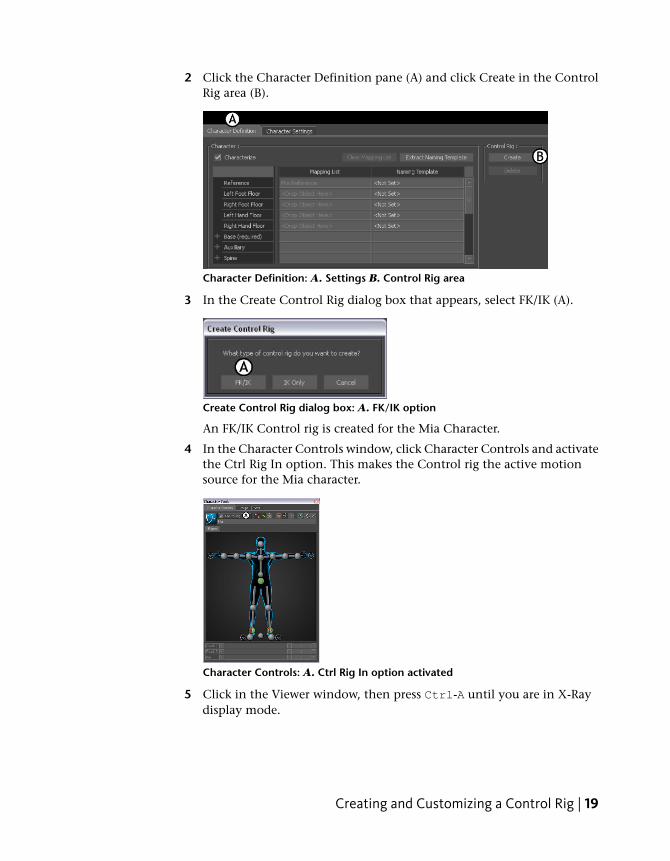
2 Click the Character Definition pane (A) and click Create in the ControlRig area (B).
Character Definition: A. Settings B. Control Rig area
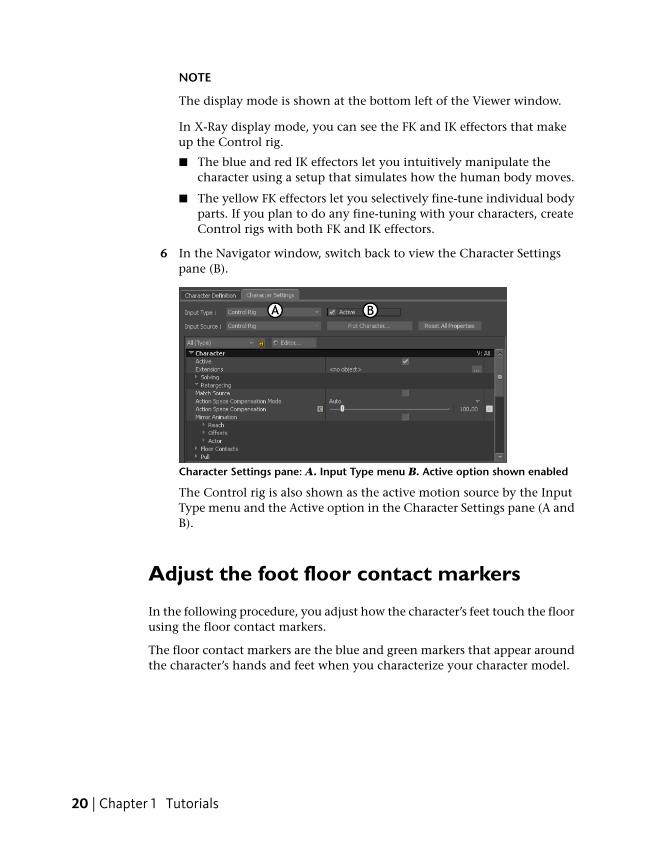
3 In the Create Control Rig dialog box that appears, select FK/IK (A).
Create Control Rig dialog box: A. FK/IK option
An FK/IK Control rig is created for the Mia Character.
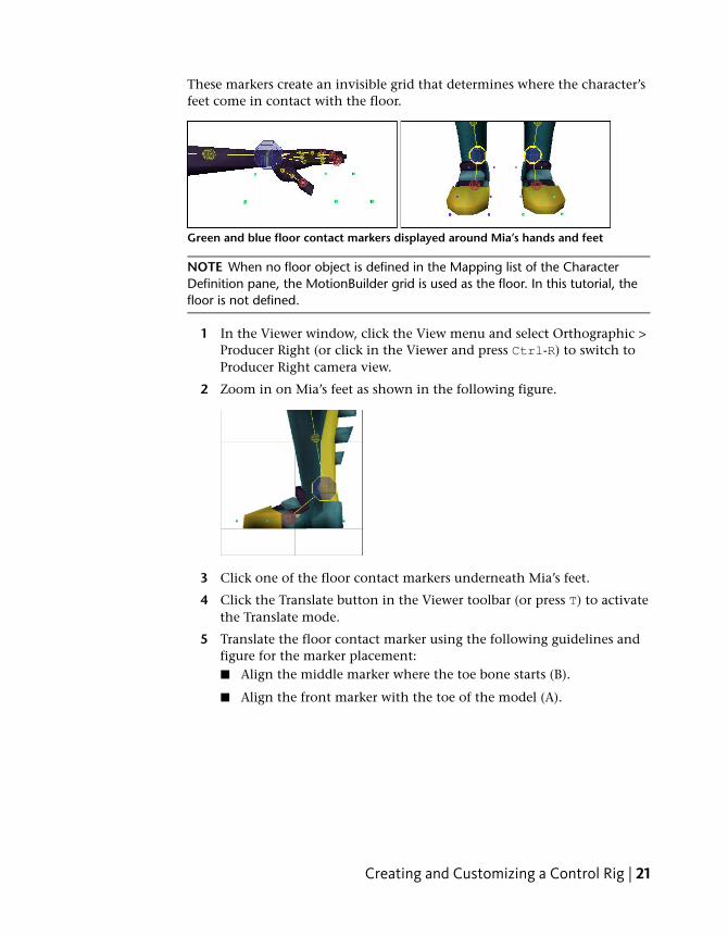
4 In the Character Controls window, click Character Controls and activatethe Ctrl Rig In option. This makes the Control rig the active motionsource for the Mia character.
Character Controls: A. Ctrl Rig In option activated
5 Click in the Viewer window, then press Ctrl-A until you are in X-Raydisplay mode.
Creating and Customizing a Control Rig | 19
NOTE
The display mode is shown at the bottom left of the Viewer window.
In X-Ray display mode, you can see the FK and IK effectors that makeup the Control rig.
■ The blue and red IK effectors let you intuitively manipulate thecharacter using a setup that simulates how the human body moves.
■ The yellow FK effectors let you selectively fine-tune individual bodyparts. If you plan to do any fine-tuning with your characters, createControl rigs with both FK and IK effectors.
6 In the Navigator window, switch back to view the Character Settingspane (B).
Character Settings pane: A. Input Type menu B. Active option shown enabled
The Control rig is also shown as the active motion source by the InputType menu and the Active option in the Character Settings pane (A andB).
Adjust the foot floor contact markers
In the following procedure, you adjust how the character’s feet touch the floorusing the floor contact markers.
The floor contact markers are the blue and green markers that appear aroundthe character’s hands and feet when you characterize your character model.
20 | Chapter 1 Tutorials
These markers create an invisible grid that determines where the character’sfeet come in contact with the floor.
Green and blue floor contact markers displayed around Mia’s hands and feet
NOTE When no floor object is defined in the Mapping list of the CharacterDefinition pane, the MotionBuilder grid is used as the floor. In this tutorial, thefloor is not defined.
1 In the Viewer window, click the View menu and select Orthographic >Producer Right (or click in the Viewer and press Ctrl-R) to switch toProducer Right camera view.
2 Zoom in on Mia’s feet as shown in the following figure.
3 Click one of the floor contact markers underneath Mia’s feet.
4 Click the Translate button in the Viewer toolbar (or press T) to activatethe Translate mode.
5 Translate the floor contact marker using the following guidelines andfigure for the marker placement:■ Align the middle marker where the toe bone starts (B).
■ Align the front marker with the toe of the model (A).
Creating and Customizing a Control Rig | 21
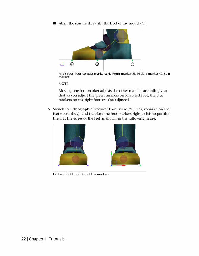
■ Align the rear marker with the heel of the model (C).
Mia’s foot floor contact markers: A. Front marker B. Middle marker C. Rearmarker
NOTE
Moving one foot marker adjusts the other markers accordingly sothat as you adjust the green markers on Mia’s left foot, the bluemarkers on the right foot are also adjusted.
6 Switch to Orthographic Producer Front view (Ctrl-F), zoom in on thefeet (Ctrl-drag), and translate the foot markers right or left to positionthem at the edges of the feet as shown in the following figure.
Left and right position of the markers
22 | Chapter 1 Tutorials
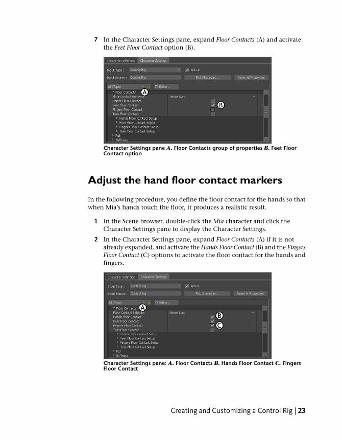
7 In the Character Settings pane, expand Floor Contacts (A) and activatethe Feet Floor Contact option (B).
Character Settings pane A. Floor Contacts group of properties B. Feet FloorContact option
Adjust the hand floor contact markers
In the following procedure, you define the floor contact for the hands so thatwhen Mia’s hands touch the floor, it produces a realistic result.
1 In the Scene browser, double-click the Mia character and click theCharacter Settings pane to display the Character Settings.
2 In the Character Settings pane, expand Floor Contacts (A) if it is notalready expanded, and activate the Hands Floor Contact (B) and the FingersFloor Contact (C) options to activate the floor contact for the hands andfingers.
Character Settings pane: A. Floor Contacts B. Hands Floor Contact C. FingersFloor Contact
Creating and Customizing a Control Rig | 23
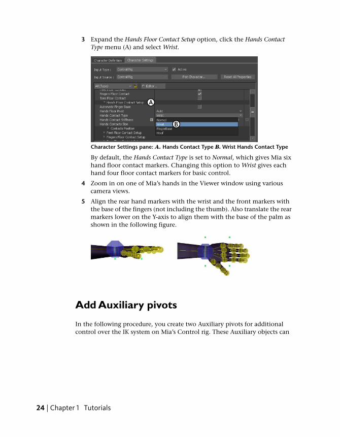
3 Expand the Hands Floor Contact Setup option, click the Hands ContactType menu (A) and select Wrist.
Character Settings pane: A. Hands Contact Type B. Wrist Hands Contact Type
By default, the Hands Contact Type is set to Normal, which gives Mia sixhand floor contact markers. Changing this option to Wrist gives eachhand four floor contact markers for basic control.
4 Zoom in on one of Mia’s hands in the Viewer window using variouscamera views.
5 Align the rear hand markers with the wrist and the front markers withthe base of the fingers (not including the thumb). Also translate the rearmarkers lower on the Y-axis to align them with the base of the palm asshown in the following figure.
Add Auxiliary pivots
In the following procedure, you create two Auxiliary pivots for additionalcontrol over the IK system on Mia’s Control rig. These Auxiliary objects can
24 | Chapter 1 Tutorials
be used to create realistic rotation on Mia’s feet as she walks. They also makeit easier to rotate Mia’s feet while creating keyframe animation.
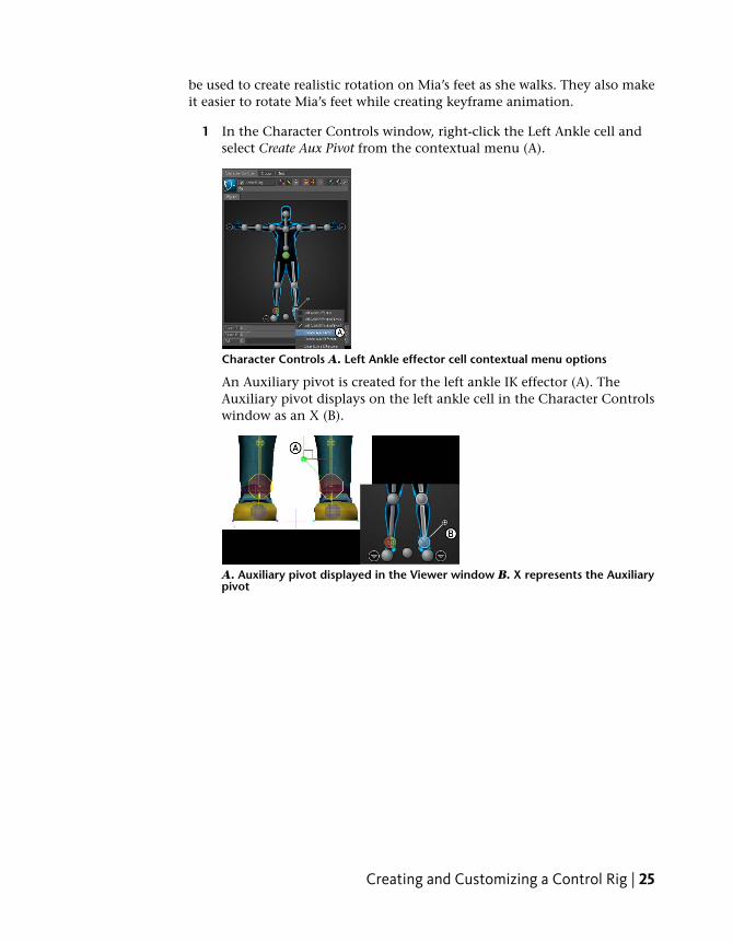
1 In the Character Controls window, right-click the Left Ankle cell andselect Create Aux Pivot from the contextual menu (A).
Character Controls A. Left Ankle effector cell contextual menu options
An Auxiliary pivot is created for the left ankle IK effector (A). TheAuxiliary pivot displays on the left ankle cell in the Character Controlswindow as an X (B).
A. Auxiliary pivot displayed in the Viewer window B. X represents the Auxiliarypivot
Creating and Customizing a Control Rig | 25
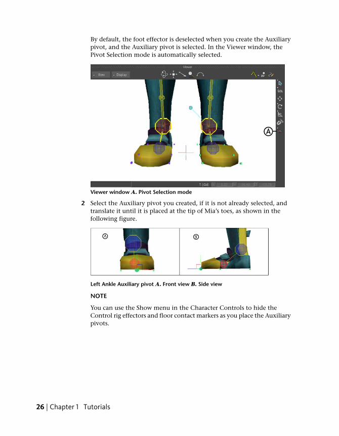
By default, the foot effector is deselected when you create the Auxiliarypivot, and the Auxiliary pivot is selected. In the Viewer window, thePivot Selection mode is automatically selected.
Viewer window A. Pivot Selection mode
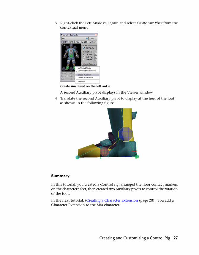
2 Select the Auxiliary pivot you created, if it is not already selected, andtranslate it until it is placed at the tip of Mia’s toes, as shown in thefollowing figure.
Left Ankle Auxiliary pivot A. Front view B. Side view
NOTE
You can use the Show menu in the Character Controls to hide theControl rig effectors and floor contact markers as you place the Auxiliarypivots.
26 | Chapter 1 Tutorials
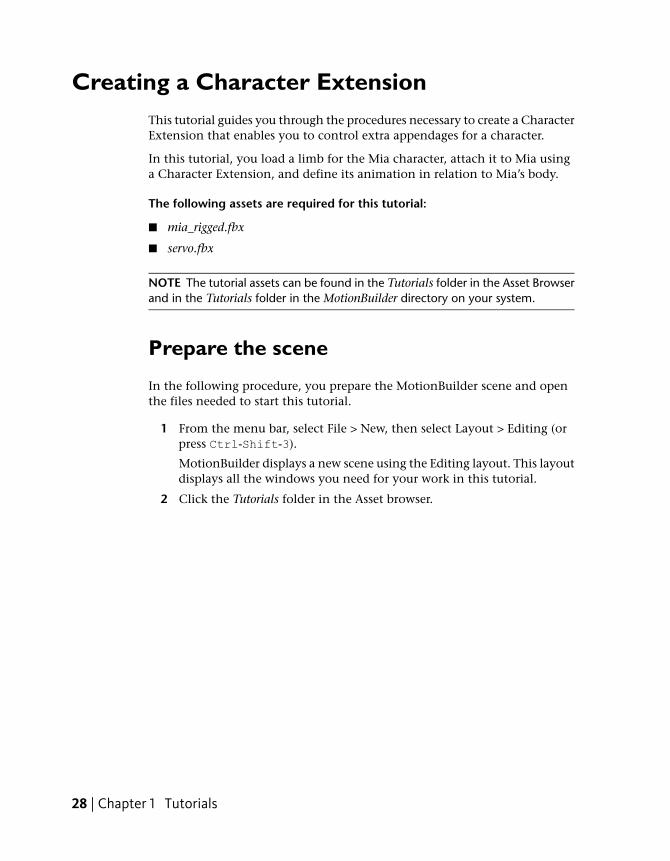
3 Right-click the Left Ankle cell again and select Create Aux Pivot from thecontextual menu.
Create Aux Pivot on the left ankle
A second Auxiliary pivot displays in the Viewer window.
4 Translate the second Auxiliary pivot to display at the heel of the foot,as shown in the following figure.
Summary
In this tutorial, you created a Control rig, arranged the floor contact markerson the character’s feet, then created two Auxiliary pivots to control the rotationof the foot.
In the next tutorial, (Creating a Character Extension (page 28)), you add aCharacter Extension to the Mia character.
Creating and Customizing a Control Rig | 27
Creating a Character ExtensionThis tutorial guides you through the procedures necessary to create a CharacterExtension that enables you to control extra appendages for a character.
In this tutorial, you load a limb for the Mia character, attach it to Mia usinga Character Extension, and define its animation in relation to Mia’s body.
The following assets are required for this tutorial:
■ mia_rigged.fbx
■ servo.fbx
NOTE The tutorial assets can be found in the Tutorials folder in the Asset Browserand in the Tutorials folder in the MotionBuilder directory on your system.
Prepare the scene
In the following procedure, you prepare the MotionBuilder scene and openthe files needed to start this tutorial.
1 From the menu bar, select File > New, then select Layout > Editing (orpress Ctrl-Shift-3).
MotionBuilder displays a new scene using the Editing layout. This layoutdisplays all the windows you need for your work in this tutorial.
2 Click the Tutorials folder in the Asset browser.
28 | Chapter 1 Tutorials
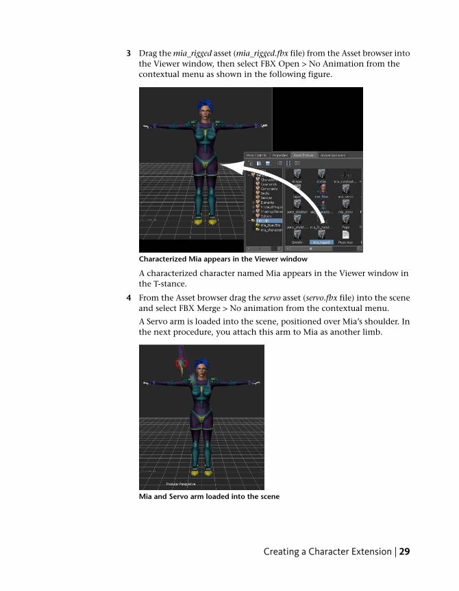
3 Drag the mia_rigged asset (mia_rigged.fbx file) from the Asset browser intothe Viewer window, then select FBX Open > No Animation from thecontextual menu as shown in the following figure.
Characterized Mia appears in the Viewer window
A characterized character named Mia appears in the Viewer window inthe T-stance.
4 From the Asset browser drag the servo asset (servo.fbx file) into the sceneand select FBX Merge > No animation from the contextual menu.
A Servo arm is loaded into the scene, positioned over Mia’s shoulder. Inthe next procedure, you attach this arm to Mia as another limb.
Mia and Servo arm loaded into the scene
Creating a Character Extension | 29
5 Choose File > Save As.
The Save File dialog appears.
6 Navigate to a directory other than the default MotionBuilderTutorialsdirectory where you want to save the file and click Save.
The Save Options dialog appears.
7 Click Save.
Choosing to save the file to a directory other than the defaultMotionBuilderTutorials directory ensures you do not overwrite theoriginal .fbx file.
Connect the extra limb to the character
In the following procedure, you create a Parent-Child relationship betweenthe Servo arm and Mia’s shoulder.
1 Switch to X-Ray display mode (Ctrl-A) in the Viewer window.
NOTE Toggle between Normal mode, Models Only mode, and X-Ray modeusing he keyboard shortcuts Ctrl-A.
2 In the Character Controls window, make sure Mia is selected as thecurrent character.
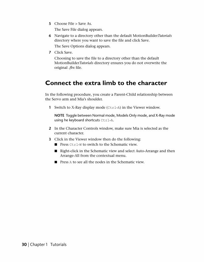
3 Click in the Viewer window then do the following:■ Press Ctrl-W to switch to the Schematic view.
■ Right-click in the Schematic view and select Auto-Arrange and thenArrange-All from the contextual menu.
■ Press A to see all the nodes in the Schematic view.
30 | Chapter 1 Tutorials
The Schematic view displays a hierarchy for Mia’s skeleton (A), Mia’sControl rig (B), and a third hierarchy for the Servo arm(“ServoMaster”, C).
Schematic view of hierarchies in the scene: A. Mia’s skeleton B. Mia’s Controlrig C. The Servo arm
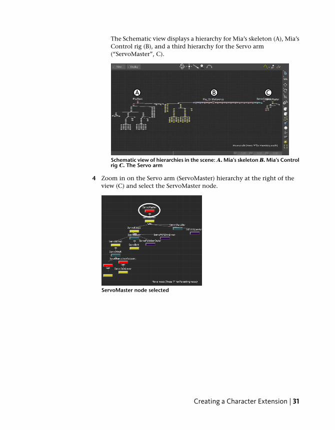
4 Zoom in on the Servo arm (ServoMaster) hierarchy at the right of theview (C) and select the ServoMaster node.
ServoMaster node selected
Creating a Character Extension | 31
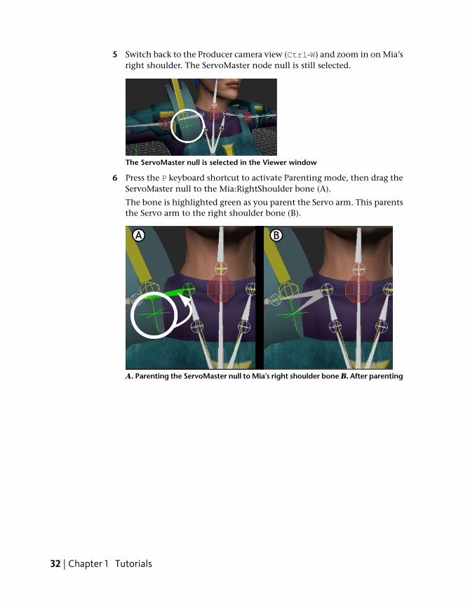
5 Switch back to the Producer camera view (Ctrl-W) and zoom in on Mia’sright shoulder. The ServoMaster node null is still selected.
The ServoMaster null is selected in the Viewer window
6 Press the P keyboard shortcut to activate Parenting mode, then drag theServoMaster null to the Mia:RightShoulder bone (A).
The bone is highlighted green as you parent the Servo arm. This parentsthe Servo arm to the right shoulder bone (B).
A. Parenting the ServoMaster null to Mia’s right shoulder bone B. After parenting
32 | Chapter 1 Tutorials
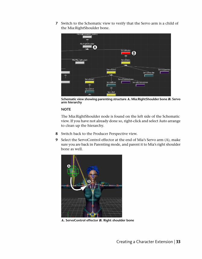
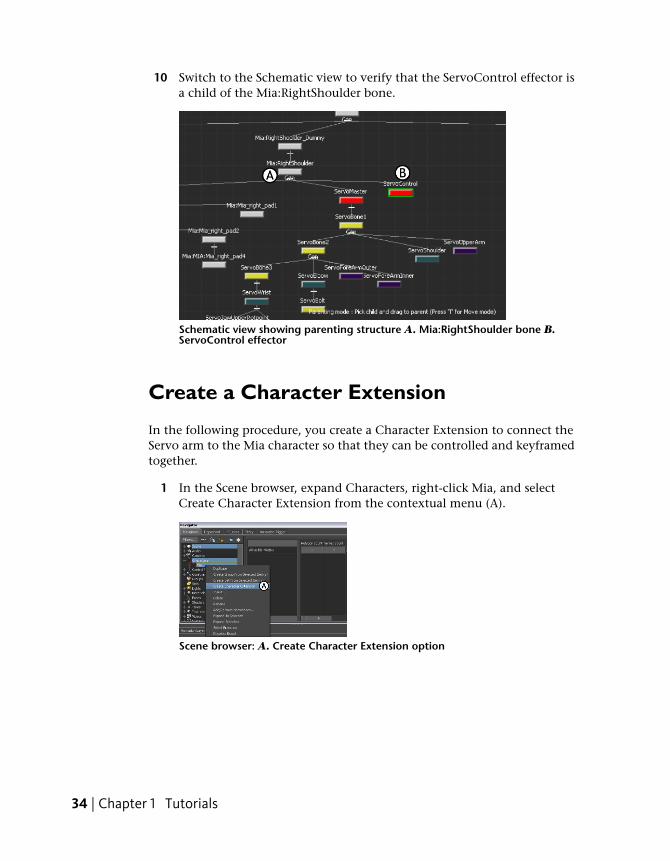
7 Switch to the Schematic view to verify that the Servo arm is a child ofthe Mia:RightShoulder bone.
Schematic view showing parenting structure A. Mia:RightShoulder bone B. Servoarm hierarchy
NOTE
The Mia:RightShoulder node is found on the left side of the Schematicview. If you have not already done so, right-click and select Auto arrangeto clean up the hierarchy.
8 Switch back to the Producer Perspective view.
9 Select the ServoControl effector at the end of Mia’s Servo arm (A), makesure you are back in Parenting mode, and parent it to Mia’s right shoulderbone as well.
A. ServoControl effector B. Right shoulder bone
Creating a Character Extension | 33
10 Switch to the Schematic view to verify that the ServoControl effector isa child of the Mia:RightShoulder bone.
Schematic view showing parenting structure A. Mia:RightShoulder bone B.ServoControl effector
Create a Character Extension
In the following procedure, you create a Character Extension to connect theServo arm to the Mia character so that they can be controlled and keyframedtogether.
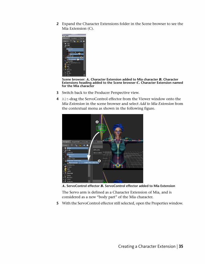
1 In the Scene browser, expand Characters, right-click Mia, and selectCreate Character Extension from the contextual menu (A).
Scene browser: A. Create Character Extension option
34 | Chapter 1 Tutorials
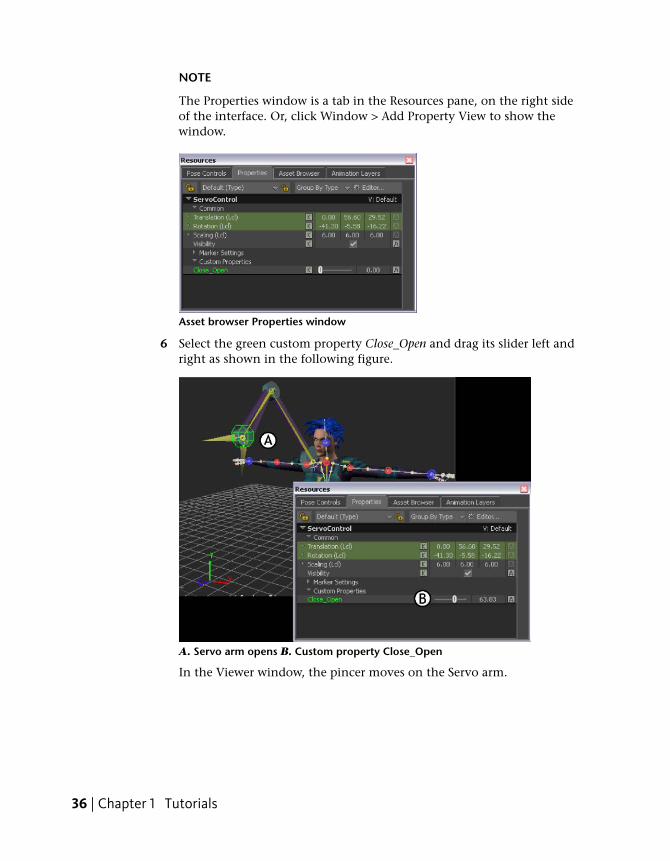
2 Expand the Character Extensions folder in the Scene browser to see theMia Extension (C).
Scene browser: A. Character Extension added to Mia character B. CharacterExtensions heading added to the Scene browser C. Character Extension namedfor the Mia character
3 Switch back to the Producer Perspective view.
4 Alt-drag the ServoControl effector from the Viewer window onto theMia Extension in the scene browser and select Add to Mia Extension fromthe contextual menu as shown in the following figure.
A. ServoControl effector B. ServoControl effector added to Mia Extension
The Servo arm is defined as a Character Extension of Mia, and isconsidered as a new “body part” of the Mia character.
5 With the ServoControl effector still selected, open the Properties window.
Creating a Character Extension | 35
NOTE
The Properties window is a tab in the Resources pane, on the right sideof the interface. Or, click Window > Add Property View to show thewindow.
Asset browser Properties window
6 Select the green custom property Close_Open and drag its slider left andright as shown in the following figure.
A. Servo arm opens B. Custom property Close_Open
In the Viewer window, the pincer moves on the Servo arm.
36 | Chapter 1 Tutorials
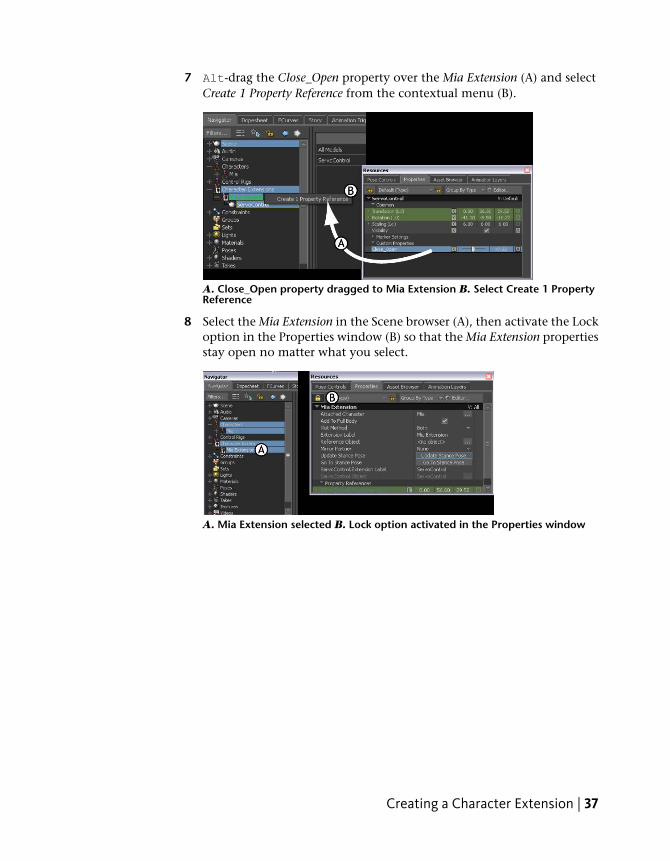
7 Alt-drag the Close_Open property over the Mia Extension (A) and selectCreate 1 Property Reference from the contextual menu (B).
A. Close_Open property dragged to Mia Extension B. Select Create 1 PropertyReference
8 Select the Mia Extension in the Scene browser (A), then activate the Lockoption in the Properties window (B) so that the Mia Extension propertiesstay open no matter what you select.
A. Mia Extension selected B. Lock option activated in the Properties window
Creating a Character Extension | 37
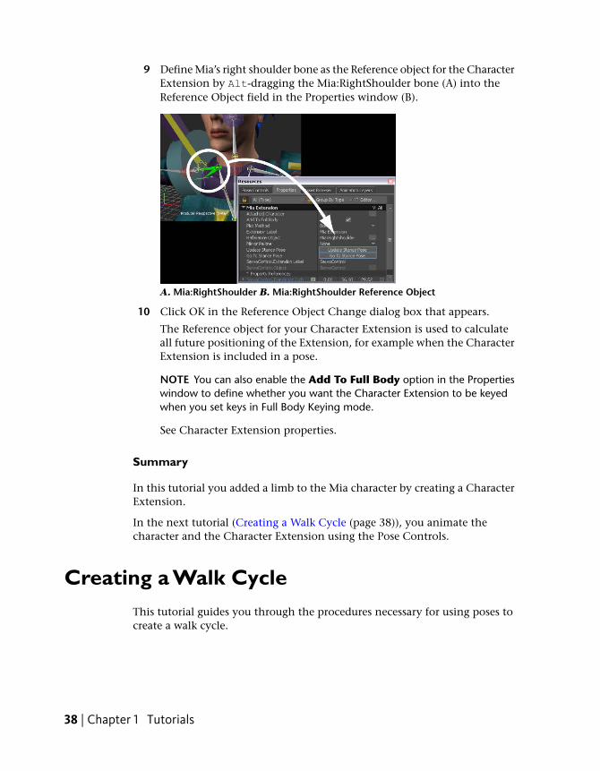
9 Define Mia’s right shoulder bone as the Reference object for the CharacterExtension by Alt-dragging the Mia:RightShoulder bone (A) into theReference Object field in the Properties window (B).
A. Mia:RightShoulder B. Mia:RightShoulder Reference Object
10 Click OK in the Reference Object Change dialog box that appears.
The Reference object for your Character Extension is used to calculateall future positioning of the Extension, for example when the CharacterExtension is included in a pose.
NOTE You can also enable the Add To Full Body option in the Propertieswindow to define whether you want the Character Extension to be keyedwhen you set keys in Full Body Keying mode.
See Character Extension properties.
Summary
In this tutorial you added a limb to the Mia character by creating a CharacterExtension.
In the next tutorial (Creating a Walk Cycle (page 38)), you animate thecharacter and the Character Extension using the Pose Controls.
Creating a Walk CycleThis tutorial guides you through the procedures necessary for using poses tocreate a walk cycle.
38 | Chapter 1 Tutorials
The following asset is required for this tutorial:
■ mia_servo.fbx
NOTE The tutorial assets can be found in the Tutorials folder in the Asset Browserand in the Tutorials folder in the MotionBuilder directory on your system.
Prepare the scene
In the following procedure, you prepare the MotionBuilder scene and openthe files needed to start this tutorial.
1 From the menu bar, select File > New, then select Layout > Editing (orpress Ctrl-Shift-3).
MotionBuilder displays a new 3D scene using the Editing layout. Thislayout displays all the windows you need for your work in this tutorial.
2 Click the Tutorials folder in the Asset browser.
3 Drag the mia_servo asset (mia_servo.fbx file) into the Viewer window,then select FBX Open > No Animation from the contextual menu thatappears.
A model named Mia (mia_servo asset) appears in the Viewer window asshown in the following figure. This character includes a “Servo arm”that is parented to the right shoulder bone and added as a CharacterExtension.
Creating a Walk Cycle | 39
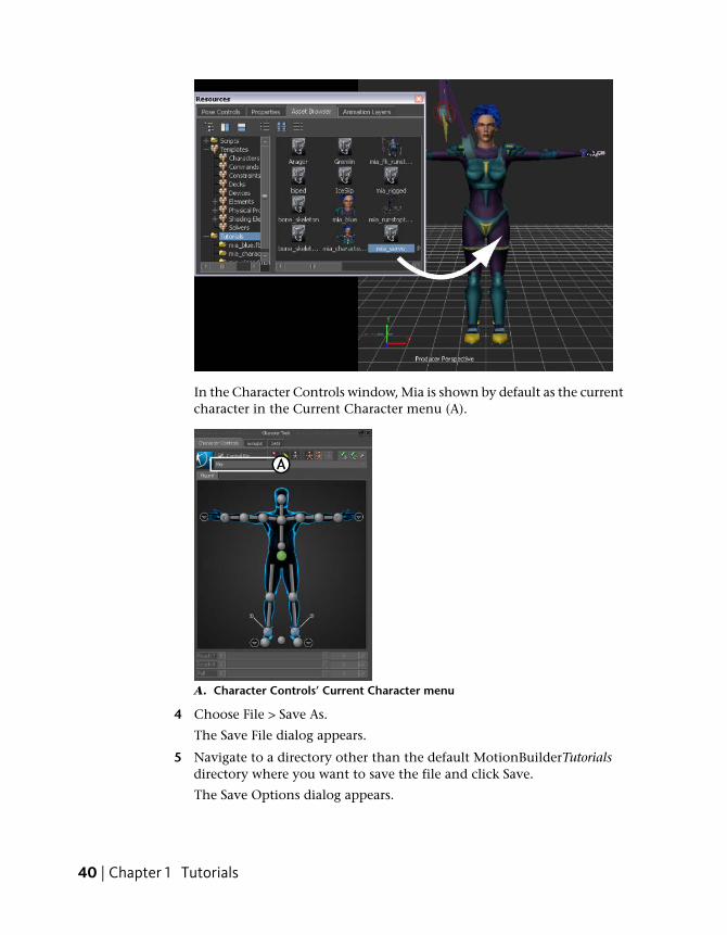
In the Character Controls window, Mia is shown by default as the currentcharacter in the Current Character menu (A).
A. Character Controls’ Current Character menu
4 Choose File > Save As.
The Save File dialog appears.
5 Navigate to a directory other than the default MotionBuilderTutorialsdirectory where you want to save the file and click Save.
The Save Options dialog appears.
40 | Chapter 1 Tutorials
6 Click Save.
Choosing to save the file to a directory other than the defaultMotionBuilderTutorials directory ensures you do not overwrite theoriginal .fbx file.
Create poses
In the following procedures, you create several full body poses on yourcharacter, including the Character Extension, to create a walk cycle.
Position the character:
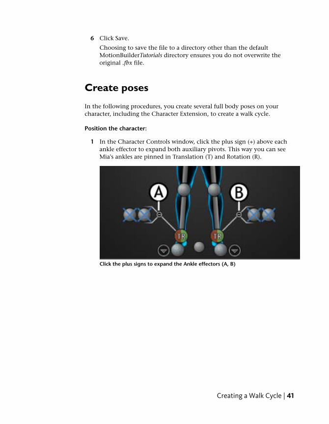
1 In the Character Controls window, click the plus sign (+) above eachankle effector to expand both auxiliary pivots. This way you can seeMia's ankles are pinned in Translation (T) and Rotation (R).
Click the plus signs to expand the Ankle effectors (A, B)
Creating a Walk Cycle | 41
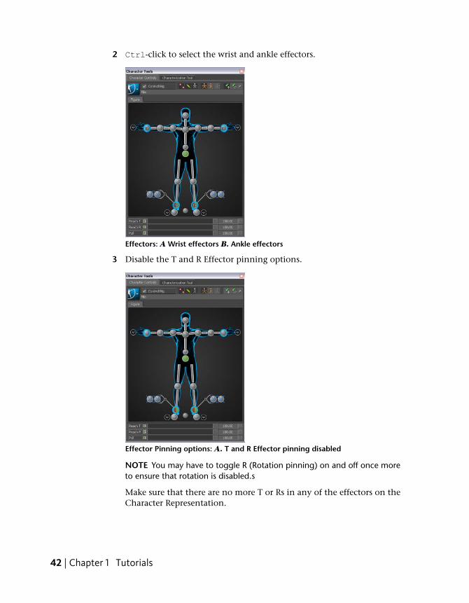
2 Ctrl-click to select the wrist and ankle effectors.
Effectors: A Wrist effectors B. Ankle effectors
3 Disable the T and R Effector pinning options.
Effector Pinning options: A. T and R Effector pinning disabled
NOTE You may have to toggle R (Rotation pinning) on and off once moreto ensure that rotation is disabled.s
Make sure that there are no more T or Rs in any of the effectors on theCharacter Representation.
42 | Chapter 1 Tutorials
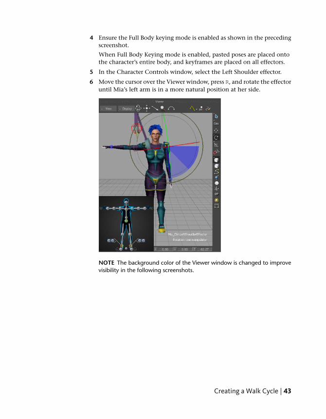
4 Ensure the Full Body keying mode is enabled as shown in the precedingscreenshot.
When Full Body Keying mode is enabled, pasted poses are placed ontothe character’s entire body, and keyframes are placed on all effectors.
5 In the Character Controls window, select the Left Shoulder effector.
6 Move the cursor over the Viewer window, press R, and rotate the effectoruntil Mia’s left arm is in a more natural position at her side.
NOTE The background color of the Viewer window is changed to improvevisibility in the following screenshots.
Creating a Walk Cycle | 43
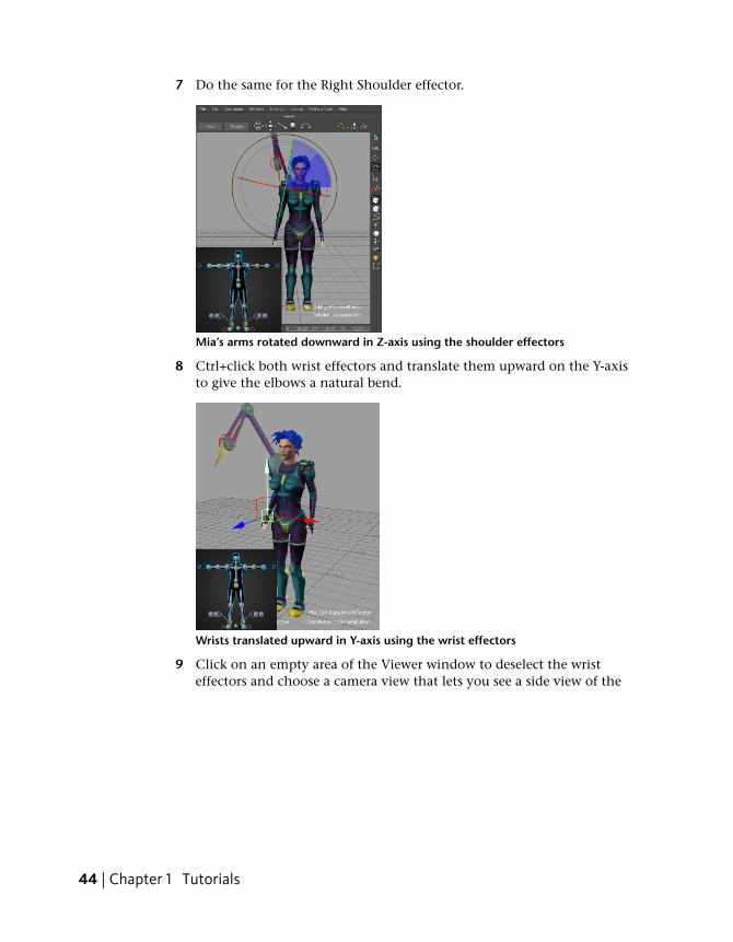
7 Do the same for the Right Shoulder effector.
Mia’s arms rotated downward in Z-axis using the shoulder effectors
8 Ctrl+click both wrist effectors and translate them upward on the Y-axisto give the elbows a natural bend.
Wrists translated upward in Y-axis using the wrist effectors
9 Click on an empty area of the Viewer window to deselect the wristeffectors and choose a camera view that lets you see a side view of the
44 | Chapter 1 Tutorials
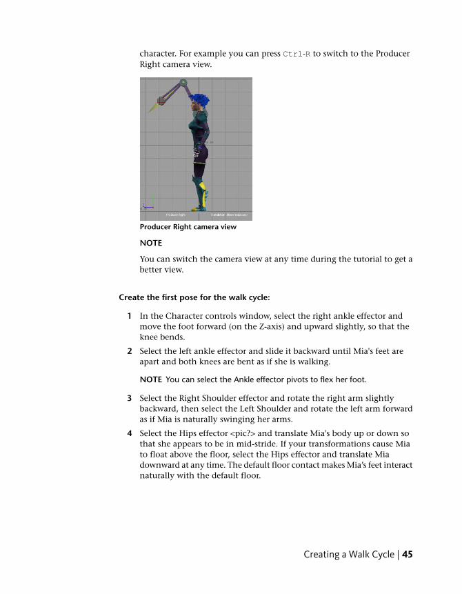
character. For example you can press Ctrl-R to switch to the ProducerRight camera view.
Producer Right camera view
NOTE
You can switch the camera view at any time during the tutorial to get abetter view.
Create the first pose for the walk cycle:
1 In the Character controls window, select the right ankle effector andmove the foot forward (on the Z-axis) and upward slightly, so that theknee bends.
2 Select the left ankle effector and slide it backward until Mia's feet areapart and both knees are bent as if she is walking.
NOTE You can select the Ankle effector pivots to flex her foot.
3 Select the Right Shoulder effector and rotate the right arm slightlybackward, then select the Left Shoulder and rotate the left arm forwardas if Mia is naturally swinging her arms.
4 Select the Hips effector <pic?> and translate Mia's body up or down sothat she appears to be in mid-stride. If your transformations cause Miato float above the floor, select the Hips effector and translate Miadownward at any time. The default floor contact makes Mia’s feet interactnaturally with the default floor.
Creating a Walk Cycle | 45
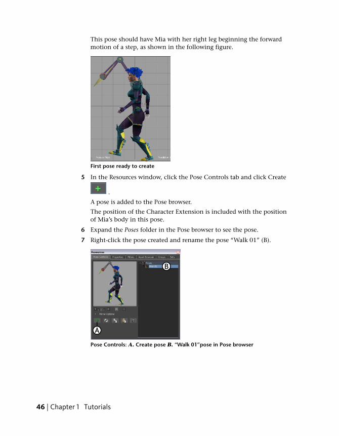
This pose should have Mia with her right leg beginning the forwardmotion of a step, as shown in the following figure.
First pose ready to create
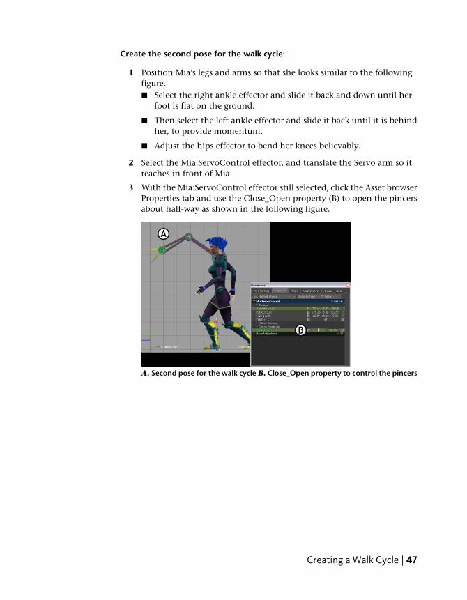
5 In the Resources window, click the Pose Controls tab and click Create
.
A pose is added to the Pose browser.
The position of the Character Extension is included with the positionof Mia’s body in this pose.
6 Expand the Poses folder in the Pose browser to see the pose.
7 Right-click the pose created and rename the pose “Walk 01” (B).
Pose Controls: A. Create pose B. “Walk 01”pose in Pose browser
46 | Chapter 1 Tutorials
Create the second pose for the walk cycle:
1 Position Mia’s legs and arms so that she looks similar to the followingfigure.■ Select the right ankle effector and slide it back and down until her
foot is flat on the ground.
■ Then select the left ankle effector and slide it back until it is behindher, to provide momentum.
■ Adjust the hips effector to bend her knees believably.
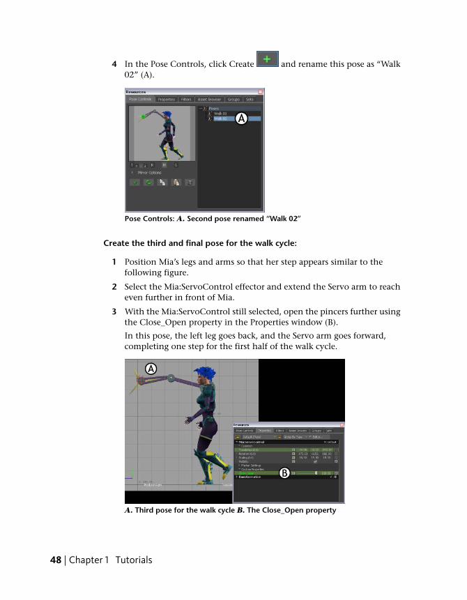
2 Select the Mia:ServoControl effector, and translate the Servo arm so itreaches in front of Mia.
3 With the Mia:ServoControl effector still selected, click the Asset browserProperties tab and use the Close_Open property (B) to open the pincersabout half-way as shown in the following figure.
A. Second pose for the walk cycle B. Close_Open property to control the pincers
Creating a Walk Cycle | 47
4 In the Pose Controls, click Create and rename this pose as “Walk02” (A).
Pose Controls: A. Second pose renamed “Walk 02”
Create the third and final pose for the walk cycle:
1 Position Mia’s legs and arms so that her step appears similar to thefollowing figure.
2 Select the Mia:ServoControl effector and extend the Servo arm to reacheven further in front of Mia.
3 With the Mia:ServoControl still selected, open the pincers further usingthe Close_Open property in the Properties window (B).
In this pose, the left leg goes back, and the Servo arm goes forward,completing one step for the first half of the walk cycle.
A. Third pose for the walk cycle B. The Close_Open property
48 | Chapter 1 Tutorials
4 In the Pose Controls, click Create and then rename this pose “Walk 03”.
You now have three poses in the scene. The three poses are listed in thePose browser.
Three poses created for the walk cycle
Create animation with poses
In the following procedure, you use the three poses you created to create onehalf of a walk cycle. By keyframing these poses at different frames, you createa short walking animation.
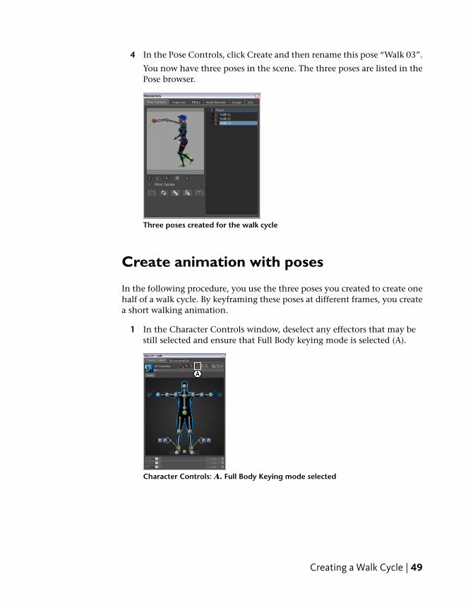
1 In the Character Controls window, deselect any effectors that may bestill selected and ensure that Full Body keying mode is selected (A).
Character Controls: A. Full Body Keying mode selected
Creating a Walk Cycle | 49
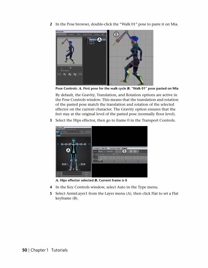
2 In the Pose browser, double-click the “Walk 01” pose to paste it on Mia.
Pose Controls: A. First pose for the walk cycle B. “Walk 01” pose pasted on Mia
By default, the Gravity, Translation, and Rotation options are active inthe Pose Controls window. This means that the translation and rotationof the pasted pose match the translation and rotation of the selectedeffector on the current character. The Gravity option ensures that thefeet stay at the original level of the pasted pose (normally floor level).
3 Select the Hips effector, then go to frame 0 in the Transport Controls.
A. Hips effector selected B. Current frame is 0
4 In the Key Controls window, select Auto in the Type menu.
5 Select AnimLayer1 from the Layer menu (A), then click Flat to set a Flatkeyframe (B).
50 | Chapter 1 Tutorials
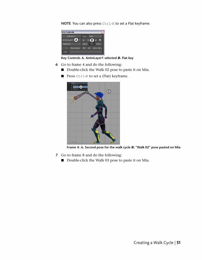
NOTE You can also press Ctrl-K to set a Flat keyframe.
Key Controls A. AnimLayer1 selected B. Flat key
6 Go to frame 4 and do the following:■ Double-click the Walk 02 pose to paste it on Mia.
■ Press Ctrl-K to set a (Flat) keyframe.
Frame 4: A. Second pose for the walk cycle B. “Walk 02” pose pasted on Mia
7 Go to frame 8 and do the following:■ Double-click the Walk 03 pose to paste it on Mia.
Creating a Walk Cycle | 51
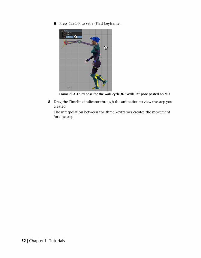
■ Press Ctrl-K to set a (Flat) keyframe.
Frame 8: A.Third pose for the walk cycle B. “Walk 03” pose pasted on Mia
8 Drag the Timeline indicator through the animation to view the step youcreated.
The interpolation between the three keyframes creates the movementfor one step.
52 | Chapter 1 Tutorials
Mirror poses
In the following procedure, you mirror the three poses from the Pose browserto create the second half of the walk cycle. By keyframing these mirrored posesafter the original poses, you complete the short walking animation.
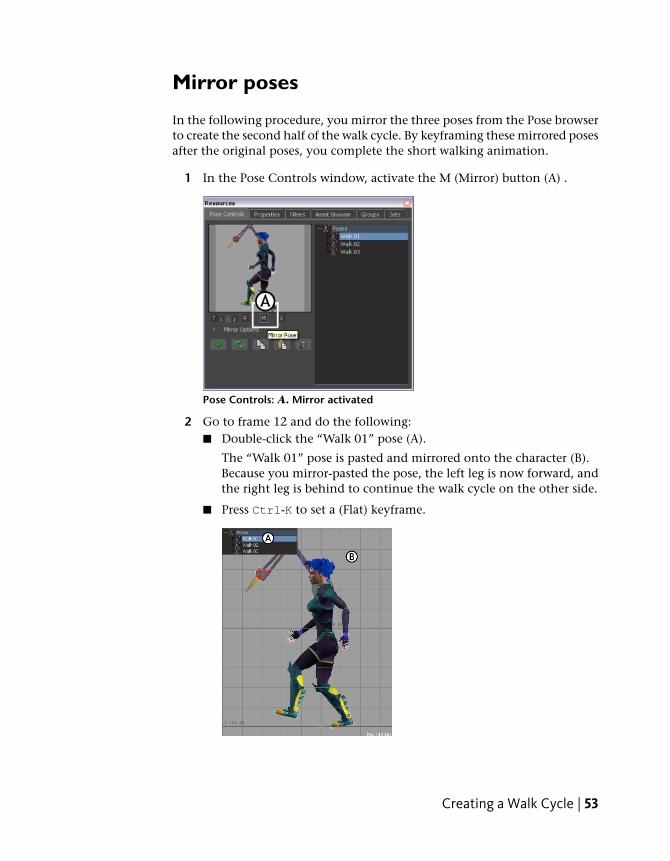
1 In the Pose Controls window, activate the M (Mirror) button (A) .
Pose Controls: A. Mirror activated
2 Go to frame 12 and do the following:■ Double-click the “Walk 01” pose (A).
The “Walk 01” pose is pasted and mirrored onto the character (B).Because you mirror-pasted the pose, the left leg is now forward, andthe right leg is behind to continue the walk cycle on the other side.
■ Press Ctrl-K to set a (Flat) keyframe.
Creating a Walk Cycle | 53
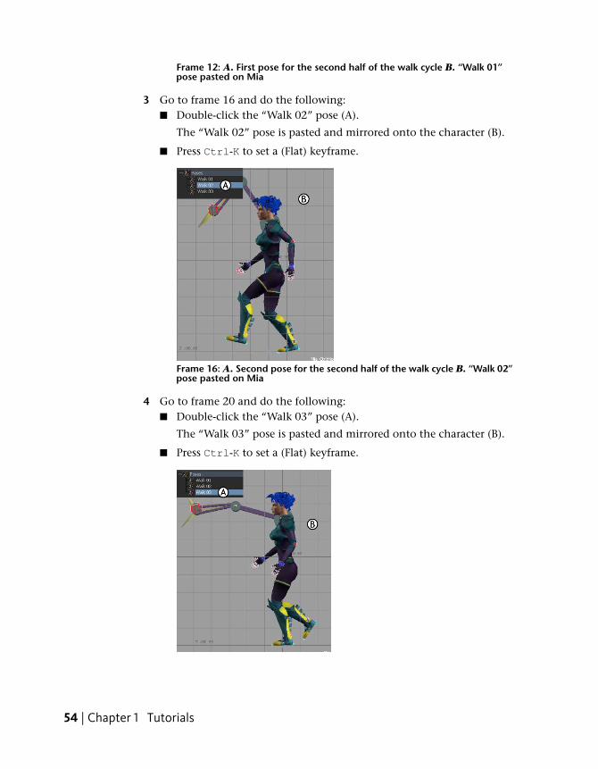
Frame 12: A. First pose for the second half of the walk cycle B. “Walk 01”pose pasted on Mia
3 Go to frame 16 and do the following:■ Double-click the “Walk 02” pose (A).
The “Walk 02” pose is pasted and mirrored onto the character (B).
■ Press Ctrl-K to set a (Flat) keyframe.
Frame 16: A. Second pose for the second half of the walk cycle B. “Walk 02”pose pasted on Mia
4 Go to frame 20 and do the following:■ Double-click the “Walk 03” pose (A).
The “Walk 03” pose is pasted and mirrored onto the character (B).
■ Press Ctrl-K to set a (Flat) keyframe.
54 | Chapter 1 Tutorials
Frame 20 A. Third pose for the second half of the walk cycle B.“Walk 03”pose pasted on Mia
Your animation now consists of six keyframes. The first threekeyframes were mirrored onto the left side of the character for thelast three keyframes, creating a complete walking movement. Tocomplete a full animation cycle, your take should begin and end withthe same position.
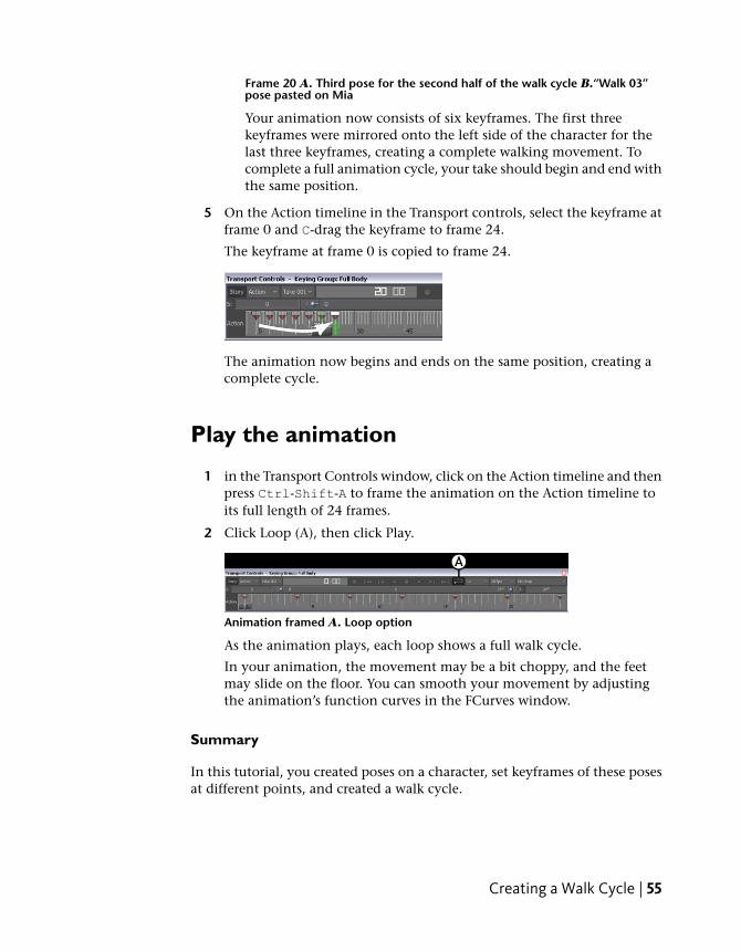
5 On the Action timeline in the Transport controls, select the keyframe atframe 0 and C-drag the keyframe to frame 24.
The keyframe at frame 0 is copied to frame 24.
The animation now begins and ends on the same position, creating acomplete cycle.
Play the animation
1 in the Transport Controls window, click on the Action timeline and thenpress Ctrl-Shift-A to frame the animation on the Action timeline toits full length of 24 frames.
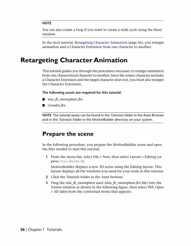
2 Click Loop (A), then click Play.
Animation framed A. Loop option
As the animation plays, each loop shows a full walk cycle.
In your animation, the movement may be a bit choppy, and the feetmay slide on the floor. You can smooth your movement by adjustingthe animation’s function curves in the FCurves window.
Summary
In this tutorial, you created poses on a character, set keyframes of these posesat different points, and created a walk cycle.
Creating a Walk Cycle | 55
NOTE
You can also create a loop if you want to create a walk cycle using the Storywindow.
In the next tutorial, Retargeting Character Animation (page 56), you retargetanimation and a Character Extension from one character to another.
Retargeting Character AnimationThis tutorial guides you through the procedures necessary to retarget animationfrom one characterized character to another. Since the source character includesa Character Extension and the target character does not, you must also retargetthe Character Extension.
The following assets are required for this tutorial:
■ mia_fk_runstopturn.fbx
■ Gremlin.fbx
NOTE The tutorial assets can be found in the Tutorials folder in the Asset Browserand in the Tutorials folder in the MotionBuilder directory on your system.
Prepare the scene
In the following procedure, you prepare the MotionBuilder scene and openthe files needed to start this tutorial.
1 From the menu bar, select File > New, then select Layout > Editing (orpress Ctrl-Shift-3).
MotionBuilder displays a new 3D scene using the Editing layout. Thislayout displays all the windows you need for your work in this tutorial.
2 Click the Tutorials folder in the Asset browser.
3 Drag the mia_fk_runstopturn asset (mia_fk_runstopturn.fbx file) into theViewer window as shown in the following figure, then select FBX Open> All takes from the contextual menu that appears.
56 | Chapter 1 Tutorials
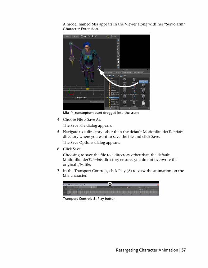
A model named Mia appears in the Viewer along with her “Servo arm”Character Extension.
Mia_fk_runstopturn asset dragged into the scene
4 Choose File > Save As.
The Save File dialog appears.
5 Navigate to a directory other than the default MotionBuilderTutorialsdirectory where you want to save the file and click Save.
The Save Options dialog appears.
6 Click Save.
Choosing to save the file to a directory other than the defaultMotionBuilderTutorials directory ensures you do not overwrite theoriginal .fbx file.
7 In the Transport Controls, click Play (A) to view the animation on theMia character.
Transport Controls A. Play button
Retargeting Character Animation | 57
Save the character animation
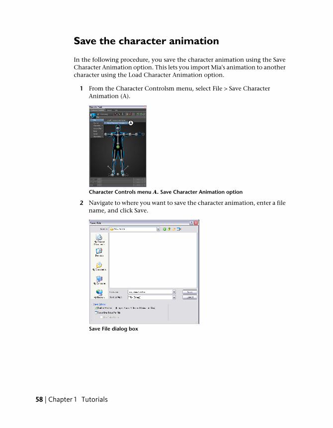
In the following procedure, you save the character animation using the SaveCharacter Animation option. This lets you import Mia's animation to anothercharacter using the Load Character Animation option.
1 From the Character Controlsm menu, select File > Save CharacterAnimation (A).
Character Controls menu A. Save Character Animation option
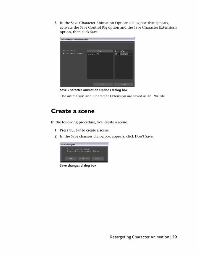
2 Navigate to where you want to save the character animation, enter a filename, and click Save.
Save File dialog box
58 | Chapter 1 Tutorials
3 In the Save Character Animation Options dialog box that appears,activate the Save Control Rig option and the Save Character Extensionsoption, then click Save.
Save Character Animation Options dialog box
The animation and Character Extension are saved as an .fbx file.
Create a scene
In the following procedure, you create a scene.
1 Press Ctrl-N to create a scene.
2 In the Save changes dialog box appears, click Don’t Save.
Save changes dialog box
Retargeting Character Animation | 59
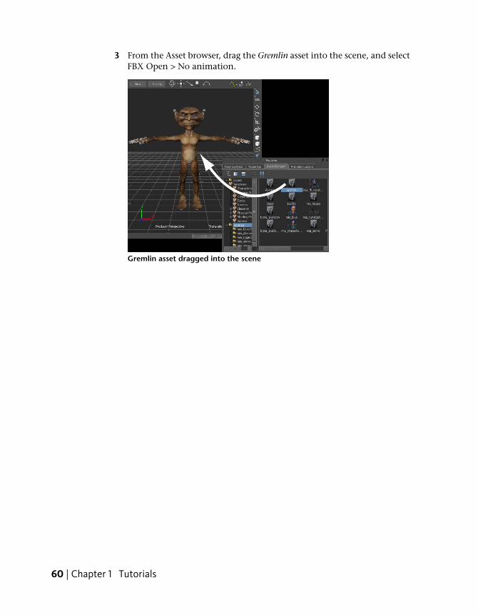
3 From the Asset browser, drag the Gremlin asset into the scene, and selectFBX Open > No animation.
Gremlin asset dragged into the scene
60 | Chapter 1 Tutorials
Load character animation
In the following procedure, you load the character animation you saved earlier.
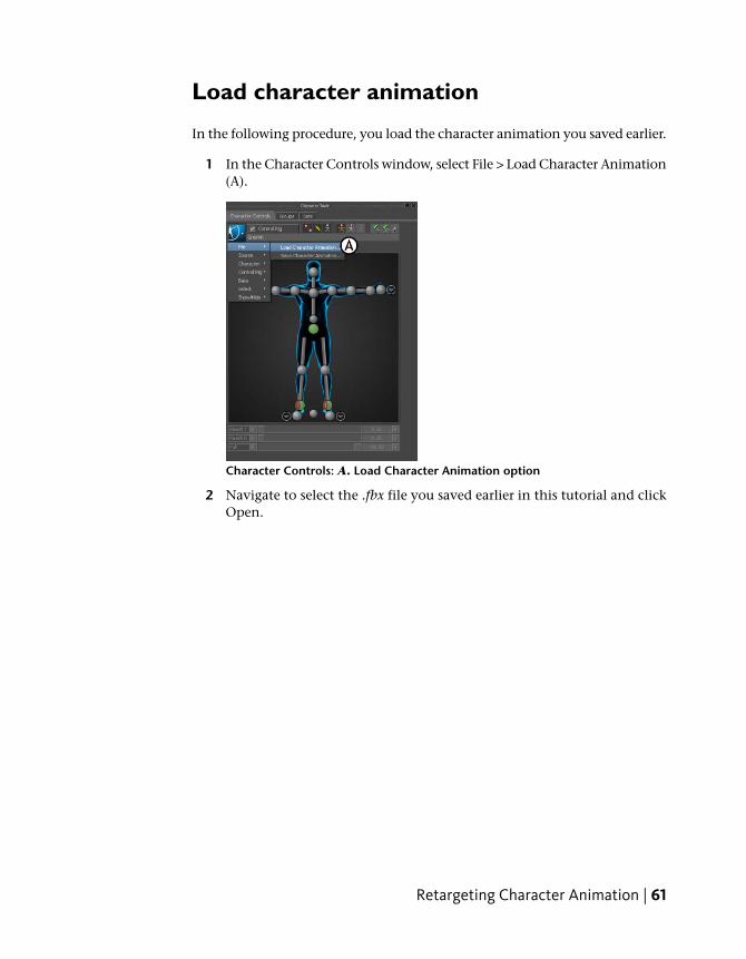
1 In the Character Controls window, select File > Load Character Animation(A).
Character Controls: A. Load Character Animation option
2 Navigate to select the .fbx file you saved earlier in this tutorial and clickOpen.
Retargeting Character Animation | 61
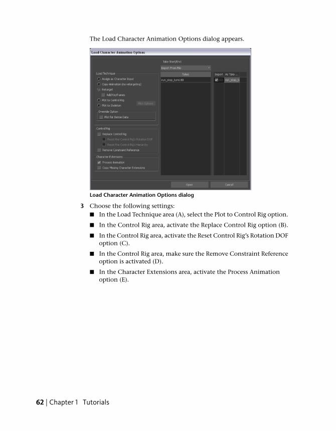
The Load Character Animation Options dialog appears.
Load Character Animation Options dialog
3 Choose the following settings:■ In the Load Technique area (A), select the Plot to Control Rig option.
■ In the Control Rig area, activate the Replace Control Rig option (B).
■ In the Control Rig area, activate the Reset Control Rig’s Rotation DOFoption (C).
■ In the Control Rig area, make sure the Remove Constraint Referenceoption is activated (D).
■ In the Character Extensions area, activate the Process Animationoption (E).
62 | Chapter 1 Tutorials
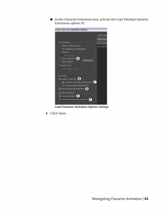
■ In the Character Extensions area, activate the Copy Missing CharacterExtensions option (F).
Load Character Animation Options settings
4 Click Open.
Retargeting Character Animation | 63
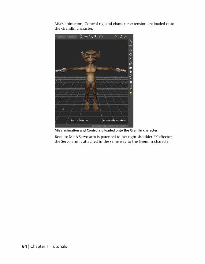
Mia’s animation, Control rig, and character extension are loaded ontothe Gremlin character.
Mia’s animation and Control rig loaded onto the Gremlin character
Because Mia’s Servo arm is parented to her right shoulder FK effector,the Servo arm is attached in the same way to the Gremlin character.
64 | Chapter 1 Tutorials
Play the animation
Play the result animation.
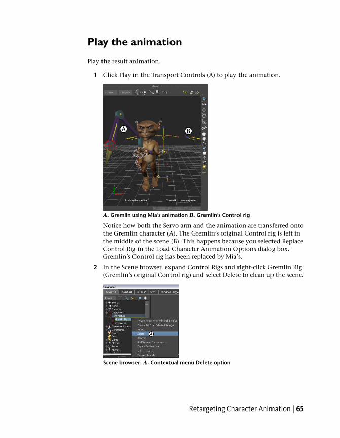
1 Click Play in the Transport Controls (A) to play the animation.
A. Gremlin using Mia’s animation B. Gremlin’s Control rig
Notice how both the Servo arm and the animation are transferred ontothe Gremlin character (A). The Gremlin’s original Control rig is left inthe middle of the scene (B). This happens because you selected ReplaceControl Rig in the Load Character Animation Options dialog box.Gremlin’s Control rig has been replaced by Mia’s.
2 In the Scene browser, expand Control Rigs and right-click Gremlin Rig(Gremlin’s original Control rig) and select Delete to clean up the scene.
Scene browser: A. Contextual menu Delete option
Retargeting Character Animation | 65
Summary
In this tutorial you retargeted animation from one characterized character toanother and you transferred the Character Extension from the source characterto the target character.
In the next tutorial, (Editing Character Animation (page 66)), you editanimation on a layer from your original animation, then merge all layers.
Editing Character AnimationThis tutorial guides you through the procedures necessary to modify animationby creating layers of animation. You modify the animation plotted to thecharacter’s Control rig on two separate layers, then combine the originalanimation and your modified animation.
The following asset is required for this tutorial:
■ mia_runstopturn.fbx
NOTE The tutorial assets can be found in the Tutorials folder in the Asset Browserand in the Tutorials folder in the MotionBuilder directory on your system.
Prepare the scene
In the following procedure, you prepare the MotionBuilder scene and openthe files needed to start this tutorial.
1 From the menu bar, select File > New, then select Layout > Editing (orpress Ctrl-Shift-3).
MotionBuilder displays a new 3D scene using the Editing layout. Thislayout displays all the windows you need for your work in this tutorial.
2 Click the Tutorials folder in the Asset browser.
3 Drag the mia_runstopturn asset (mia_runstopturn.fbx file) into the Viewerwindow (A), then select FBX Open > run_stop_turn180 from thecontextual menu that appears.
66 | Chapter 1 Tutorials
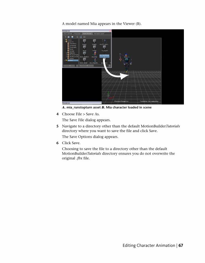
A model named Mia appears in the Viewer (B).
A. mia_runstopturn asset B. Mia character loaded in scene
4 Choose File > Save As.
The Save File dialog appears.
5 Navigate to a directory other than the default MotionBuilderTutorialsdirectory where you want to save the file and click Save.
The Save Options dialog appears.
6 Click Save.
Choosing to save the file to a directory other than the defaultMotionBuilderTutorials directory ensures you do not overwrite theoriginal .fbx file.
Editing Character Animation | 67
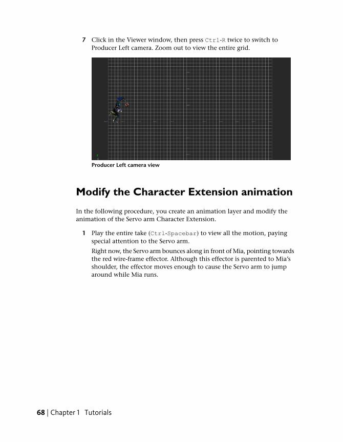
7 Click in the Viewer window, then press Ctrl-R twice to switch toProducer Left camera. Zoom out to view the entire grid.
Producer Left camera view
Modify the Character Extension animation
In the following procedure, you create an animation layer and modify theanimation of the Servo arm Character Extension.
1 Play the entire take (Ctrl-Spacebar) to view all the motion, payingspecial attention to the Servo arm.
Right now, the Servo arm bounces along in front of Mia, pointing towardsthe red wire-frame effector. Although this effector is parented to Mia’sshoulder, the effector moves enough to cause the Servo arm to jumparound while Mia runs.
68 | Chapter 1 Tutorials
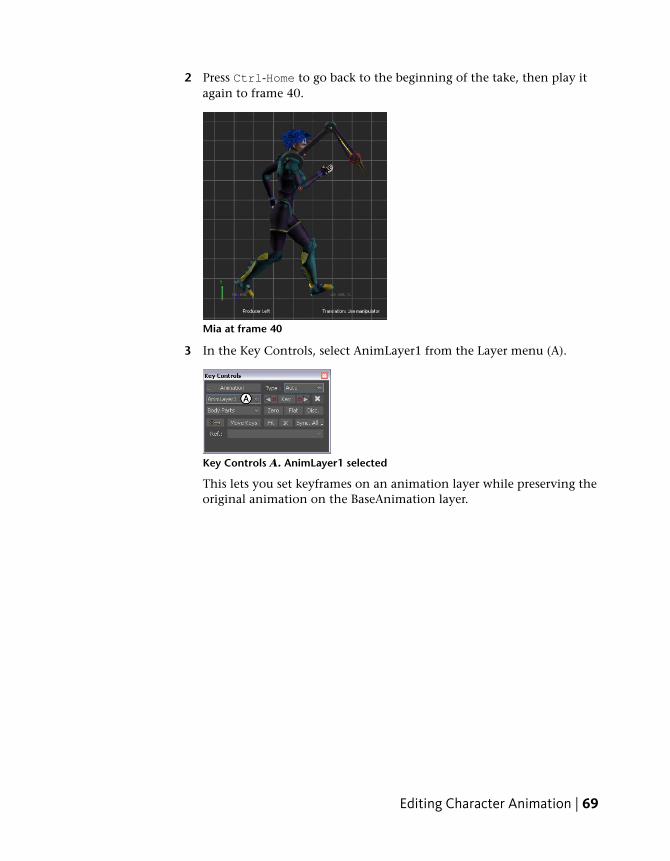
2 Press Ctrl-Home to go back to the beginning of the take, then play itagain to frame 40.
Mia at frame 40
3 In the Key Controls, select AnimLayer1 from the Layer menu (A).
Key Controls A. AnimLayer1 selected
This lets you set keyframes on an animation layer while preserving theoriginal animation on the BaseAnimation layer.
Editing Character Animation | 69
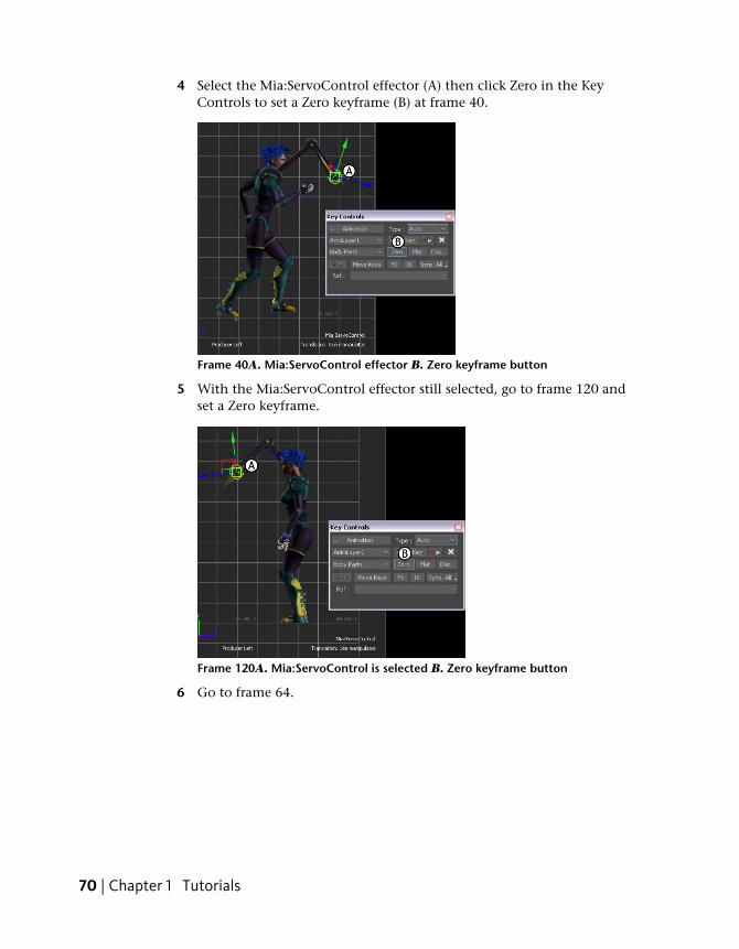
4 Select the Mia:ServoControl effector (A) then click Zero in the KeyControls to set a Zero keyframe (B) at frame 40.
Frame 40A. Mia:ServoControl effector B. Zero keyframe button
5 With the Mia:ServoControl effector still selected, go to frame 120 andset a Zero keyframe.
Frame 120A. Mia:ServoControl is selected B. Zero keyframe button
6 Go to frame 64.
70 | Chapter 1 Tutorials
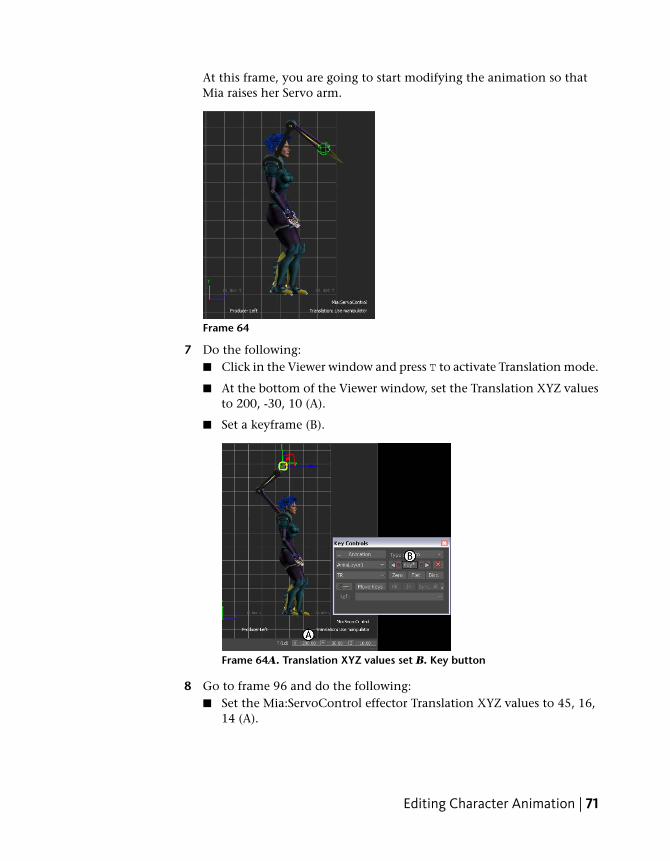
At this frame, you are going to start modifying the animation so thatMia raises her Servo arm.
Frame 64
7 Do the following:■ Click in the Viewer window and press T to activate Translation mode.
■ At the bottom of the Viewer window, set the Translation XYZ valuesto 200, -30, 10 (A).
■ Set a keyframe (B).
Frame 64A. Translation XYZ values set B. Key button
8 Go to frame 96 and do the following:■ Set the Mia:ServoControl effector Translation XYZ values to 45, 16,
14 (A).
Editing Character Animation | 71
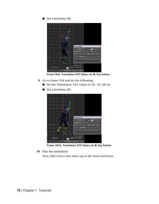
■ Set a keyframe (B).
Frame 96A. Translation XYZ Values set B. Key button
9 Go to frame 104 and do the following:■ Set the Translation XYZ values to 35, -25, 68 (A).
■ Set a keyframe (B).
Frame 104A. Translation XYZ Values set B. Key button
10 Play the animation.
Now, Mia’s Servo arm raises up as she slows and turns.
72 | Chapter 1 Tutorials
Modify the head animation
In the following procedure, you use another layer to improve the animationby making Mia turn her head as she runs, when she stops, and again justbefore she turns around.
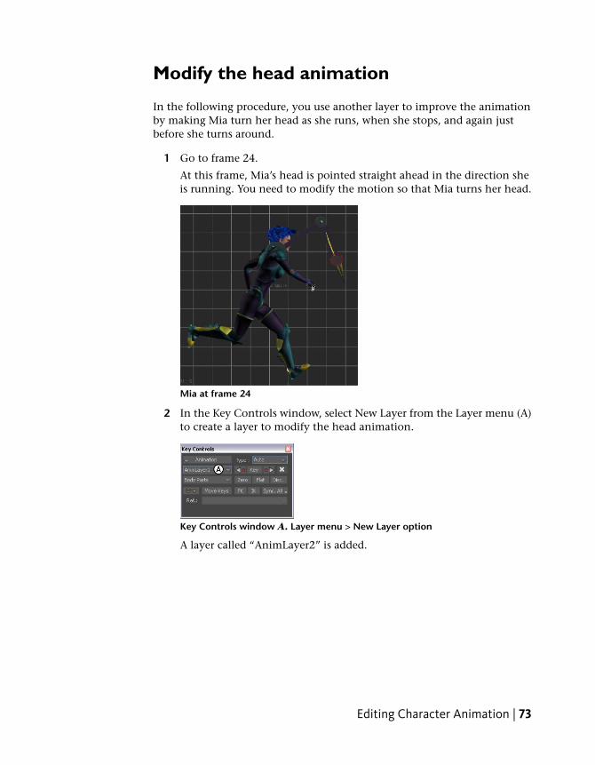
1 Go to frame 24.
At this frame, Mia’s head is pointed straight ahead in the direction sheis running. You need to modify the motion so that Mia turns her head.
Mia at frame 24
2 In the Key Controls window, select New Layer from the Layer menu (A)to create a layer to modify the head animation.
Key Controls window A. Layer menu > New Layer option
A layer called “AnimLayer2” is added.
Editing Character Animation | 73
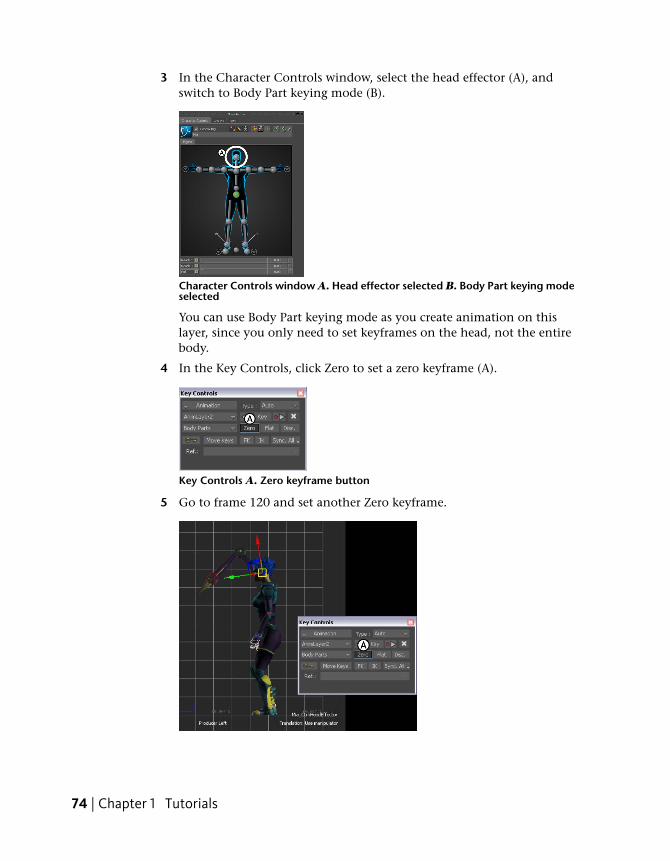
3 In the Character Controls window, select the head effector (A), andswitch to Body Part keying mode (B).
Character Controls window A. Head effector selected B. Body Part keying modeselected
You can use Body Part keying mode as you create animation on thislayer, since you only need to set keyframes on the head, not the entirebody.
4 In the Key Controls, click Zero to set a zero keyframe (A).
Key Controls A. Zero keyframe button
5 Go to frame 120 and set another Zero keyframe.
74 | Chapter 1 Tutorials
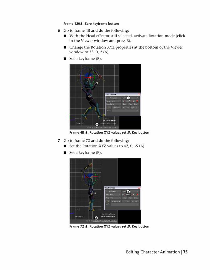
Frame 120A. Zero keyframe button
6 Go to frame 48 and do the following:■ With the Head effector still selected, activate Rotation mode (click
in the Viewer window and press R).
■ Change the Rotation XYZ properties at the bottom of the Viewerwindow to 35, 0, 2 (A).
■ Set a keyframe (B).
Frame 48 A. Rotation XYZ values set B. Key button
7 Go to frame 72 and do the following:■ Set the Rotation XYZ values to 42, 0, -5 (A).
■ Set a keyframe (B).
Frame 72 A. Rotation XYZ values set B. Key button
Editing Character Animation | 75
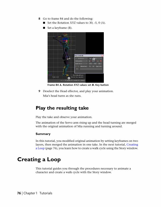
8 Go to frame 84 and do the following:■ Set the Rotation XYZ values to 30, -5, 0 (A).
■ Set a keyframe (B).
Frame 84 A. Rotation XYZ values set B. Key button
9 Deselect the Head effector, and play your animation.
Mia’s head turns as she runs.
Play the resulting take
Play the take and observe your animation.
The animation of the Servo arm rising up and the head turning are mergedwith the original animation of Mia running and turning around.
Summary
In this tutorial, you modified original animation by setting keyframes on twolayers, then merged the animation in one take. In the next tutorial, Creatinga Loop (page 76), you learn how to create a walk cycle using the Story window.
Creating a LoopThis tutorial guides you through the procedures necessary to animate acharacter and create a walk cycle with the Story window.
76 | Chapter 1 Tutorials
The following assets are required for this tutorial:
■ mia_servo.fbx
■ walkaround.fbx
NOTE The tutorial assets can be found in the Tutorials folder in the Asset Browserand in the Tutorials folder in the MotionBuilder directory on your system.
Prepare the scene
In the following procedure, you prepare the MotionBuilder scene and openthe files needed to start this tutorial.
1 From the menu bar, select File > New, then select Layout > Story (or pressCtrl-Shift-5).
MotionBuilder displays a new 3D scene using the Story layout. Thislayout displays all the windows you need for your work in this tutorial.
2 Click the Tutorials folder in the Asset browser.
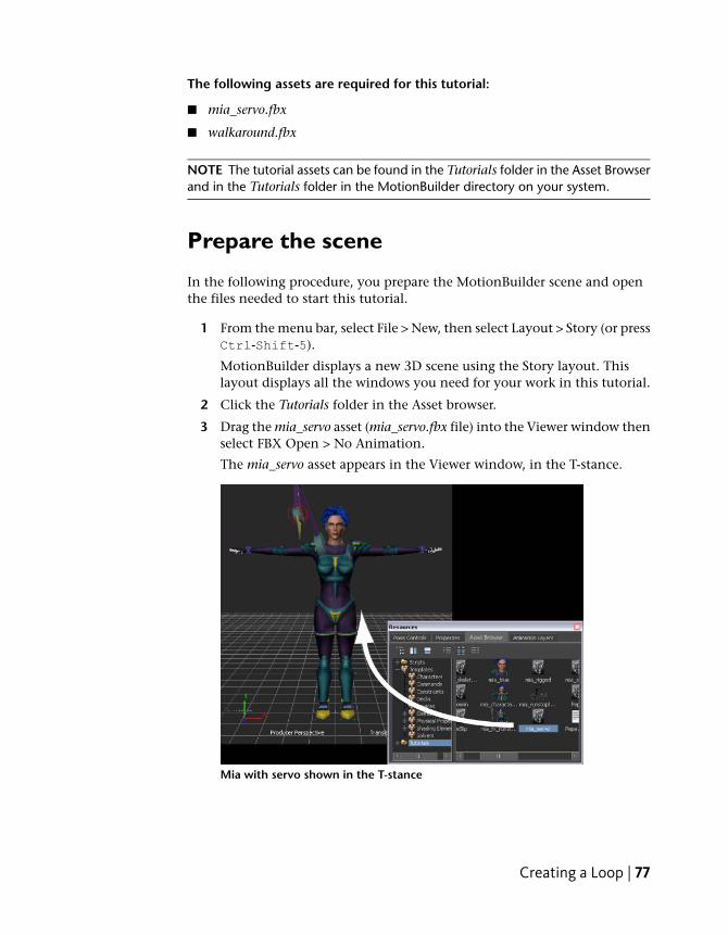
3 Drag the mia_servo asset (mia_servo.fbx file) into the Viewer window thenselect FBX Open > No Animation.
The mia_servo asset appears in the Viewer window, in the T-stance.
Mia with servo shown in the T-stance
Creating a Loop | 77
4 Choose File > Save As.
The Save File dialog appears.
5 Navigate to a directory other than the default MotionBuilderTutorialsdirectory where you want to save the file and click Save.
The Save Options dialog appears.
6 Click Save.
Choosing to save the file to a directory other than the defaultMotionBuilderTutorials directory ensures you do not overwrite theoriginal .fbx file.
Create a Character track
In the following procedure, you create a Character track in the Story window,define the character affected by the track, and add some animation.
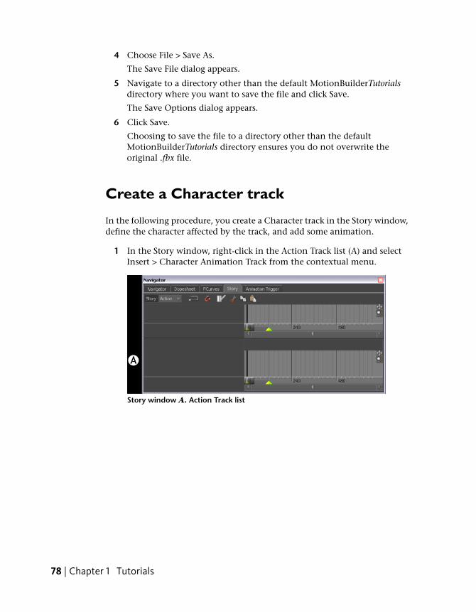
1 In the Story window, right-click in the Action Track list (A) and selectInsert > Character Animation Track from the contextual menu.
Story window A. Action Track list
78 | Chapter 1 Tutorials
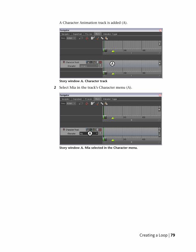
A Character Animation track is added (A).
Story window A. Character track
2 Select Mia in the track’s Character menu (A).
Story window A. Mia selected in the Character menu.
Creating a Loop | 79
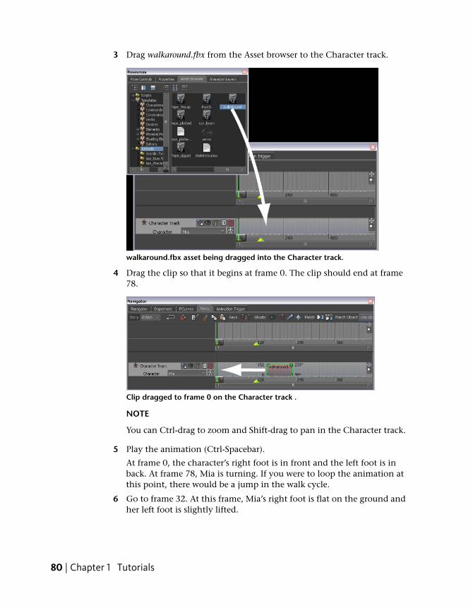
3 Drag walkaround.fbx from the Asset browser to the Character track.
walkaround.fbx asset being dragged into the Character track.
4 Drag the clip so that it begins at frame 0. The clip should end at frame78.
Clip dragged to frame 0 on the Character track .
NOTE
You can Ctrl-drag to zoom and Shift-drag to pan in the Character track.
5 Play the animation (Ctrl-Spacebar).
At frame 0, the character’s right foot is in front and the left foot is inback. At frame 78, Mia is turning. If you were to loop the animation atthis point, there would be a jump in the walk cycle.
6 Go to frame 32. At this frame, Mia’s right foot is flat on the ground andher left foot is slightly lifted.
80 | Chapter 1 Tutorials
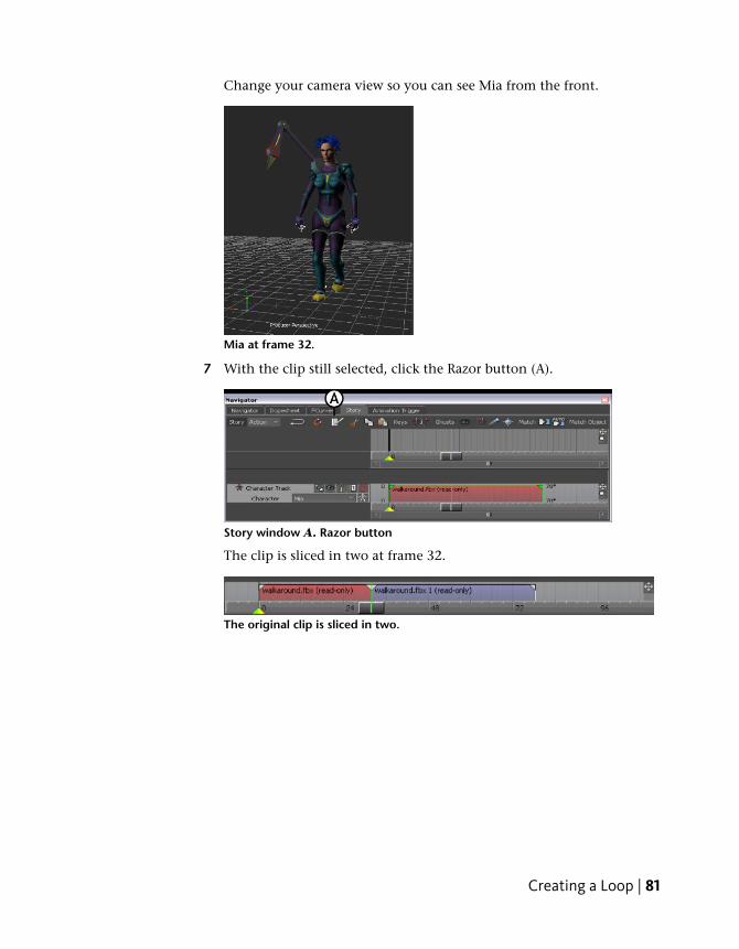
Change your camera view so you can see Mia from the front.
Mia at frame 32.
7 With the clip still selected, click the Razor button (A).
Story window A. Razor button
The clip is sliced in two at frame 32.
The original clip is sliced in two.
Creating a Loop | 81
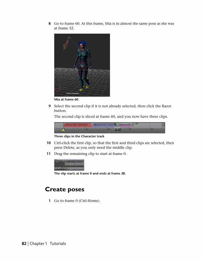
8 Go to frame 60. At this frame, Mia is in almost the same pose as she wasat frame 32.
Mia at frame 60.
9 Select the second clip if it is not already selected, then click the Razorbutton.
The second clip is sliced at frame 60, and you now have three clips.
Three clips in the Character track
10 Ctrl-click the first clip, so that the first and third clips are selected, thenpress Delete, as you only need the middle clip.
11 Drag the remaining clip to start at frame 0.
The clip starts at frame 0 and ends at frame 28.
Create poses
1 Go to frame 0 (Ctrl-Home).
82 | Chapter 1 Tutorials
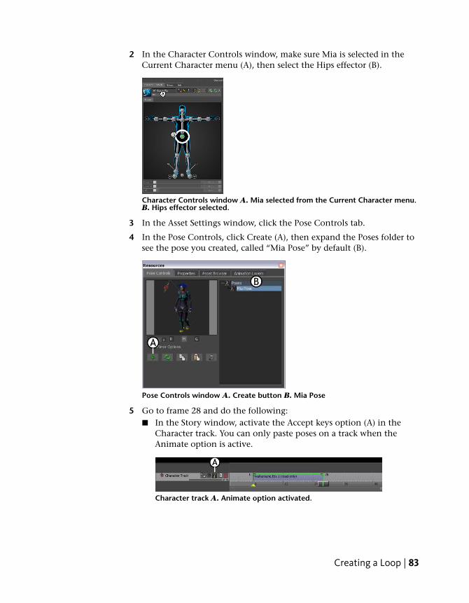
2 In the Character Controls window, make sure Mia is selected in theCurrent Character menu (A), then select the Hips effector (B).
Character Controls window A. Mia selected from the Current Character menu.B. Hips effector selected.
3 In the Asset Settings window, click the Pose Controls tab.
4 In the Pose Controls, click Create (A), then expand the Poses folder tosee the pose you created, called “Mia Pose” by default (B).
Pose Controls window A. Create button B. Mia Pose
5 Go to frame 28 and do the following:■ In the Story window, activate the Accept keys option (A) in the
Character track. You can only paste poses on a track when theAnimate option is active.
Character track A. Animate option activated.
Creating a Loop | 83
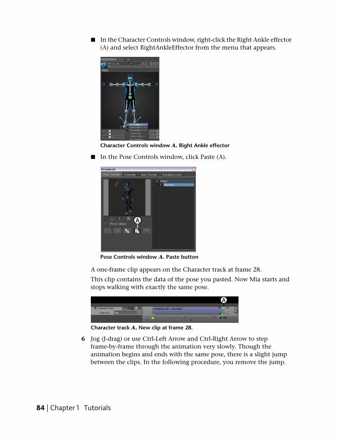
■ In the Character Controls window, right-click the Right Ankle effector(A) and select RightAnkleEffector from the menu that appears.
Character Controls window A. Right Ankle effector
■ In the Pose Controls window, click Paste (A).
Pose Controls window A. Paste button
A one-frame clip appears on the Character track at frame 28.
This clip contains the data of the pose you pasted. Now Mia starts andstops walking with exactly the same pose.
Character track A. New clip at frame 28.
6 Jog (J-drag) or use Ctrl-Left Arrow and Ctrl-Right Arrow to stepframe-by-frame through the animation very slowly. Though theanimation begins and ends with the same pose, there is a slight jumpbetween the clips. In the following procedure, you remove the jump.
84 | Chapter 1 Tutorials
Match clips
In the following procedure, you match and blend the two clips to remove thejump in the animation.
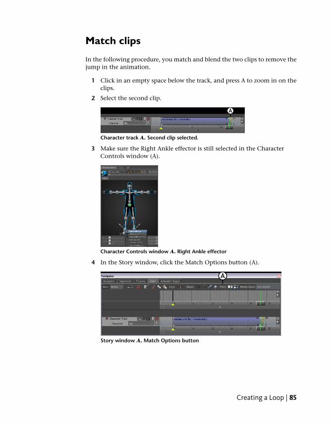
1 Click in an empty space below the track, and press A to zoom in on theclips.
2 Select the second clip.
Character track A. Second clip selected.
3 Make sure the Right Ankle effector is still selected in the CharacterControls window (A).
Character Controls window A. Right Ankle effector
4 In the Story window, click the Match Options button (A).
Story window A. Match Options button
Creating a Loop | 85
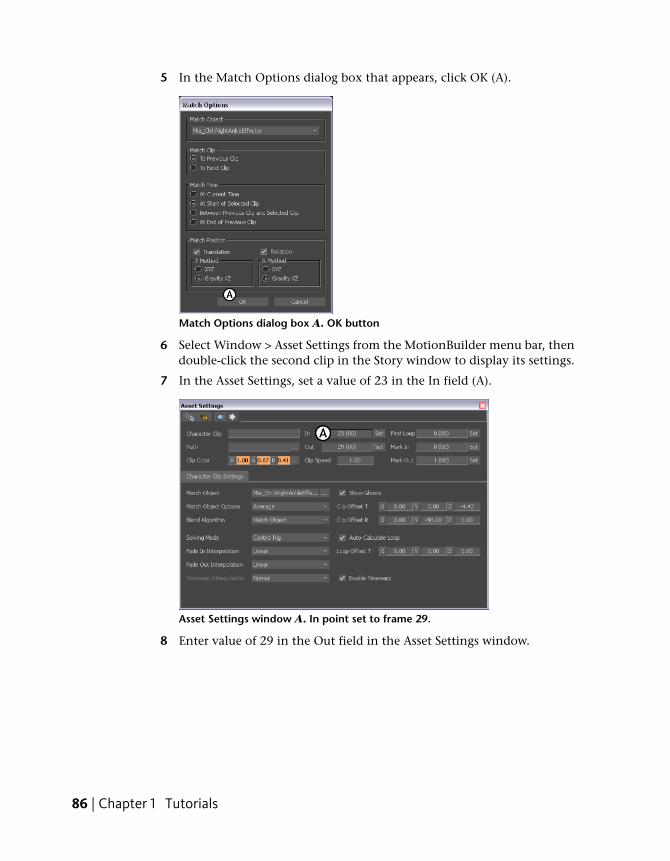
5 In the Match Options dialog box that appears, click OK (A).
Match Options dialog box A. OK button
6 Select Window > Asset Settings from the MotionBuilder menu bar, thendouble-click the second clip in the Story window to display its settings.
7 In the Asset Settings, set a value of 23 in the In field (A).
Asset Settings window A. In point set to frame 29.
8 Enter value of 29 in the Out field in the Asset Settings window.
86 | Chapter 1 Tutorials
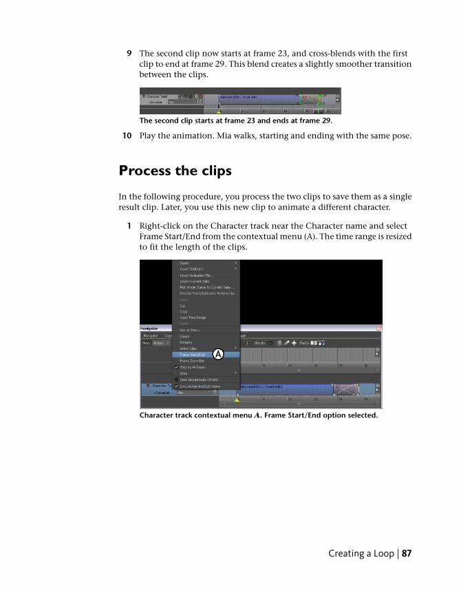
9 The second clip now starts at frame 23, and cross-blends with the firstclip to end at frame 29. This blend creates a slightly smoother transitionbetween the clips.
The second clip starts at frame 23 and ends at frame 29.
10 Play the animation. Mia walks, starting and ending with the same pose.
Process the clips
In the following procedure, you process the two clips to save them as a singleresult clip. Later, you use this new clip to animate a different character.
1 Right-click on the Character track near the Character name and selectFrame Start/End from the contextual menu (A). The time range is resizedto fit the length of the clips.
Character track contextual menu A. Frame Start/End option selected.
Creating a Loop | 87
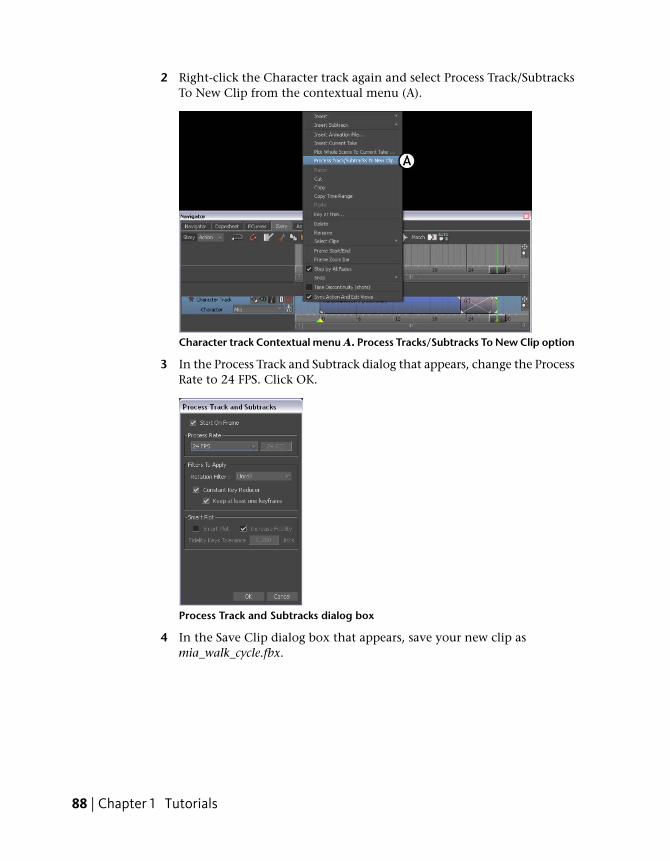
2 Right-click the Character track again and select Process Track/SubtracksTo New Clip from the contextual menu (A).
Character track Contextual menu A. Process Tracks/Subtracks To New Clip option
3 In the Process Track and Subtrack dialog that appears, change the ProcessRate to 24 FPS. Click OK.
Process Track and Subtracks dialog box
4 In the Save Clip dialog box that appears, save your new clip asmia_walk_cycle.fbx.
88 | Chapter 1 Tutorials
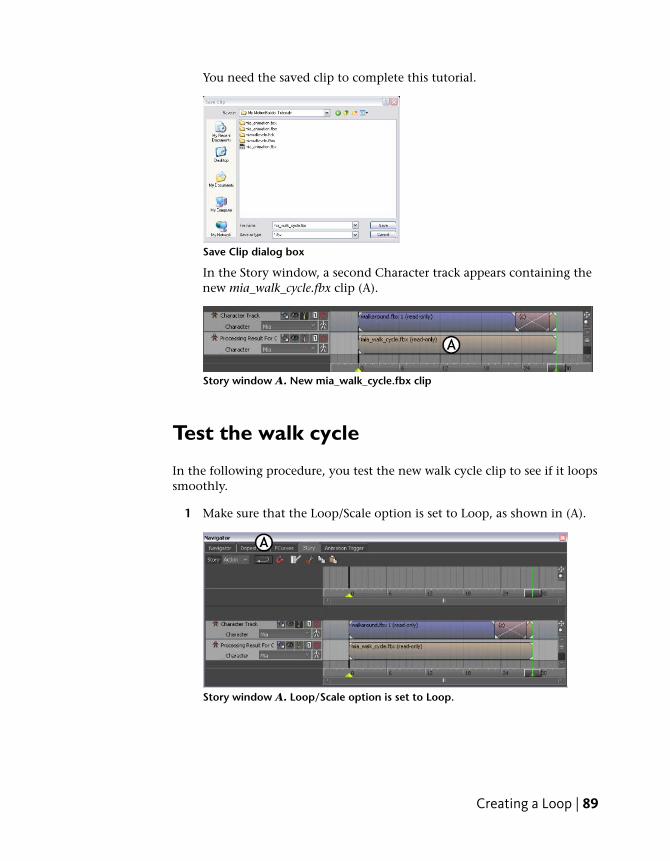
You need the saved clip to complete this tutorial.
Save Clip dialog box
In the Story window, a second Character track appears containing thenew mia_walk_cycle.fbx clip (A).
Story window A. New mia_walk_cycle.fbx clip
Test the walk cycle
In the following procedure, you test the new walk cycle clip to see if it loopssmoothly.
1 Make sure that the Loop/Scale option is set to Loop, as shown in (A).
Story window A. Loop/Scale option is set to Loop.
Creating a Loop | 89
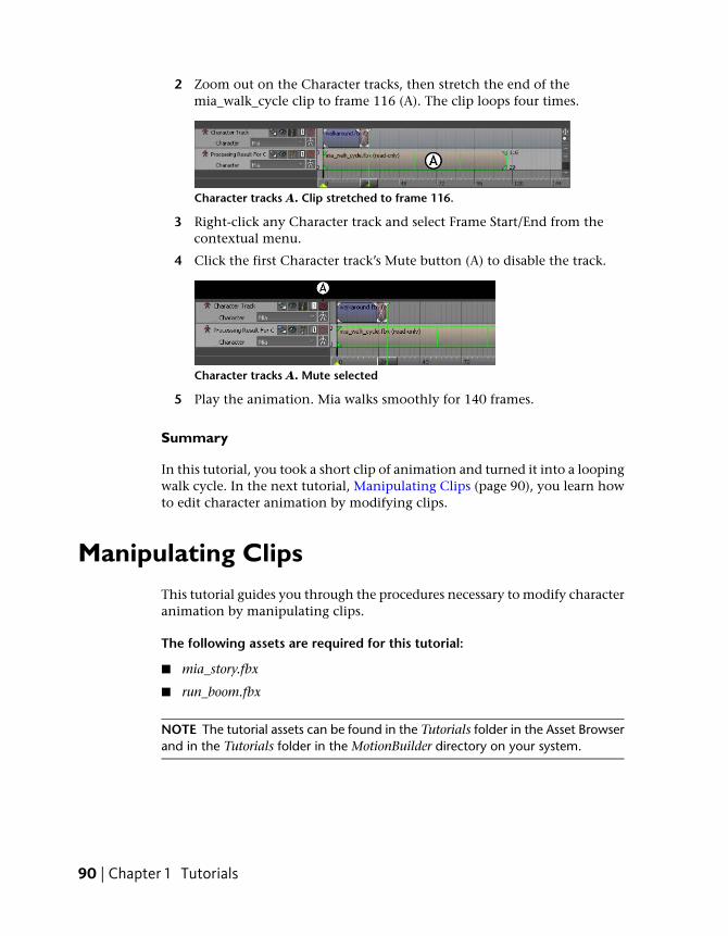
2 Zoom out on the Character tracks, then stretch the end of themia_walk_cycle clip to frame 116 (A). The clip loops four times.
Character tracks A. Clip stretched to frame 116.
3 Right-click any Character track and select Frame Start/End from thecontextual menu.
4 Click the first Character track’s Mute button (A) to disable the track.
Character tracks A. Mute selected
5 Play the animation. Mia walks smoothly for 140 frames.
Summary
In this tutorial, you took a short clip of animation and turned it into a loopingwalk cycle. In the next tutorial, Manipulating Clips (page 90), you learn howto edit character animation by modifying clips.
Manipulating ClipsThis tutorial guides you through the procedures necessary to modify characteranimation by manipulating clips.
The following assets are required for this tutorial:
■ mia_story.fbx
■ run_boom.fbx
NOTE The tutorial assets can be found in the Tutorials folder in the Asset Browserand in the Tutorials folder in the MotionBuilder directory on your system.
90 | Chapter 1 Tutorials
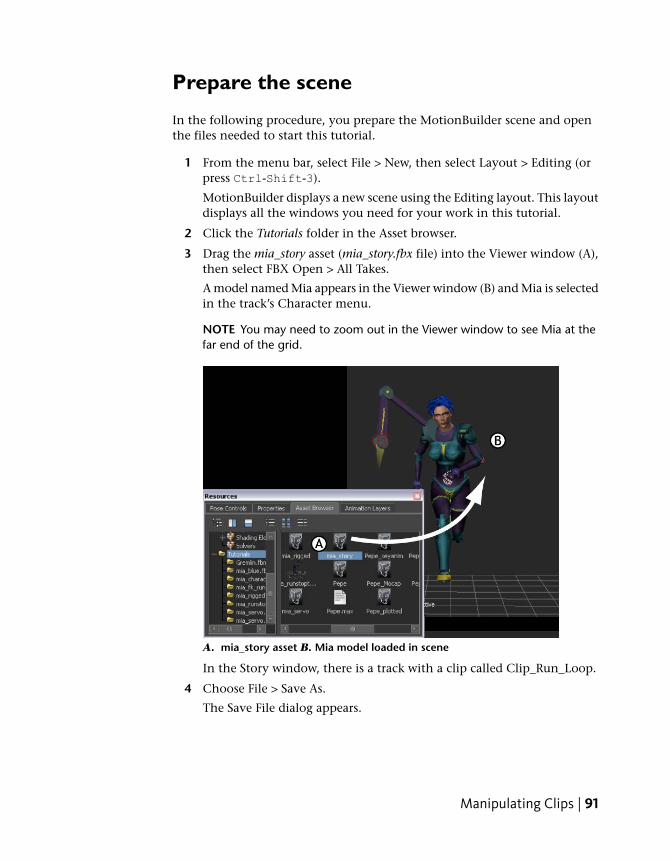
Prepare the scene
In the following procedure, you prepare the MotionBuilder scene and openthe files needed to start this tutorial.
1 From the menu bar, select File > New, then select Layout > Editing (orpress Ctrl-Shift-3).
MotionBuilder displays a new scene using the Editing layout. This layoutdisplays all the windows you need for your work in this tutorial.
2 Click the Tutorials folder in the Asset browser.
3 Drag the mia_story asset (mia_story.fbx file) into the Viewer window (A),then select FBX Open > All Takes.
A model named Mia appears in the Viewer window (B) and Mia is selectedin the track’s Character menu.
NOTE You may need to zoom out in the Viewer window to see Mia at thefar end of the grid.
A. mia_story asset B. Mia model loaded in scene
In the Story window, there is a track with a clip called Clip_Run_Loop.
4 Choose File > Save As.
The Save File dialog appears.
Manipulating Clips | 91
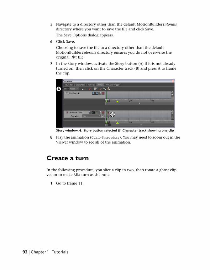
5 Navigate to a directory other than the default MotionBuilderTutorialsdirectory where you want to save the file and click Save.
The Save Options dialog appears.
6 Click Save.
Choosing to save the file to a directory other than the defaultMotionBuilderTutorials directory ensures you do not overwrite theoriginal .fbx file.
7 In the Story window, activate the Story button (A) if it is not alreadyturned on, then click on the Character track (B) and press A to framethe clip.
Story window A. Story button selected B. Character track showing one clip
8 Play the animation (Ctrl-Spacebar). You may need to zoom out in theViewer window to see all of the animation.
Create a turn
In the following procedure, you slice a clip in two, then rotate a ghost clipvector to make Mia turn as she runs.
1 Go to frame 11.
92 | Chapter 1 Tutorials
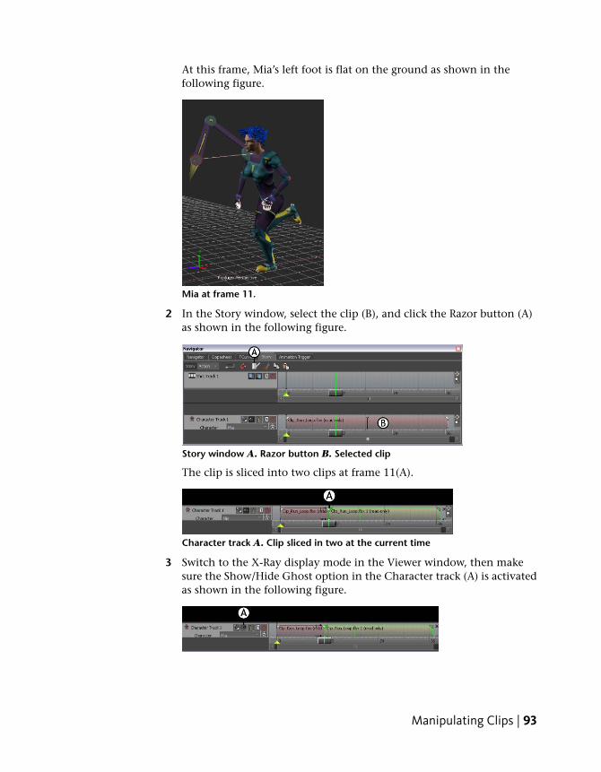
At this frame, Mia’s left foot is flat on the ground as shown in thefollowing figure.
Mia at frame 11.
2 In the Story window, select the clip (B), and click the Razor button (A)as shown in the following figure.
Story window A. Razor button B. Selected clip
The clip is sliced into two clips at frame 11(A).
Character track A. Clip sliced in two at the current time
3 Switch to the X-Ray display mode in the Viewer window, then makesure the Show/Hide Ghost option in the Character track (A) is activatedas shown in the following figure.
Manipulating Clips | 93
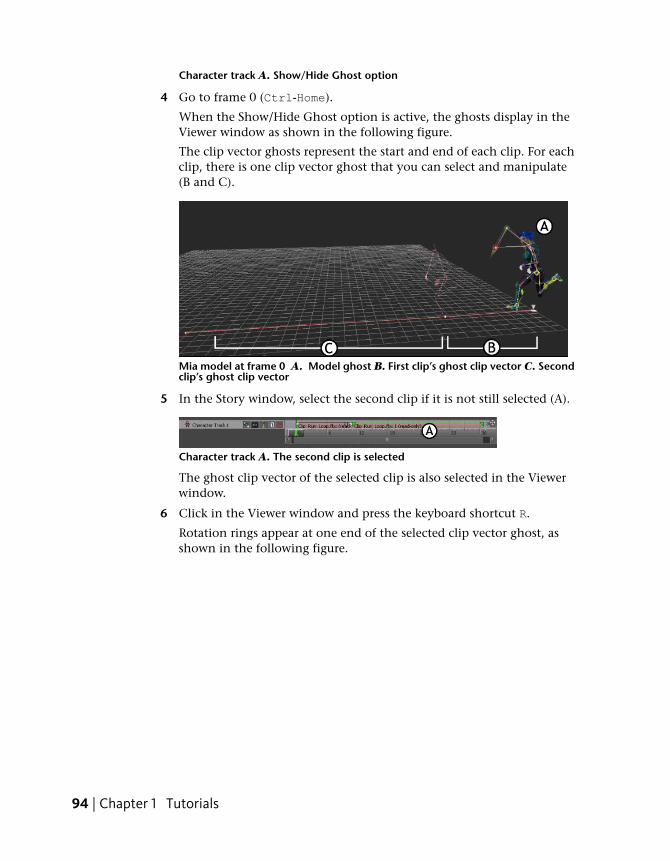
Character track A. Show/Hide Ghost option
4 Go to frame 0 (Ctrl-Home).
When the Show/Hide Ghost option is active, the ghosts display in theViewer window as shown in the following figure.
The clip vector ghosts represent the start and end of each clip. For eachclip, there is one clip vector ghost that you can select and manipulate(B and C).
Mia model at frame 0 A. Model ghost B. First clip’s ghost clip vector C. Secondclip’s ghost clip vector
5 In the Story window, select the second clip if it is not still selected (A).
Character track A. The second clip is selected
The ghost clip vector of the selected clip is also selected in the Viewerwindow.
6 Click in the Viewer window and press the keyboard shortcut R.
Rotation rings appear at one end of the selected clip vector ghost, asshown in the following figure.
94 | Chapter 1 Tutorials
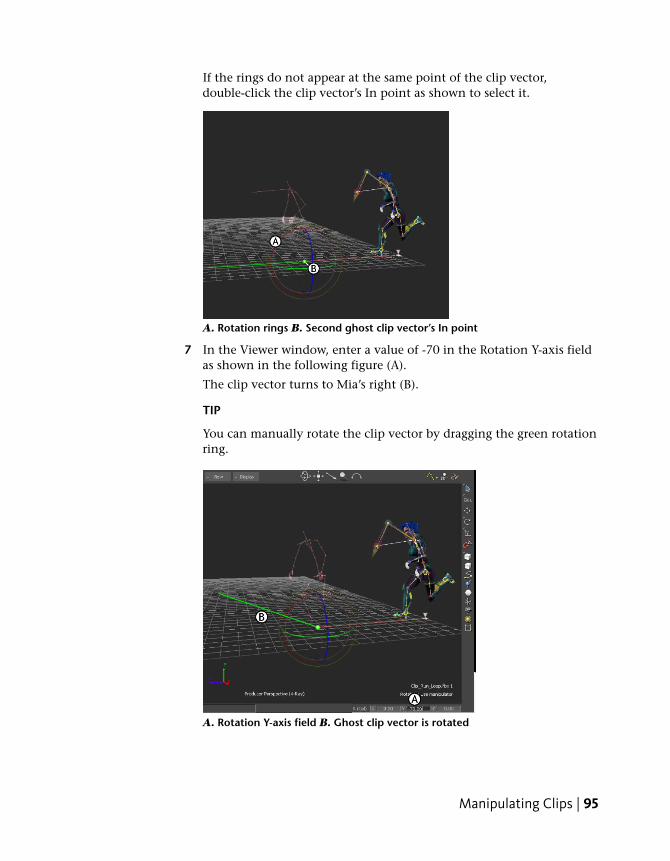
If the rings do not appear at the same point of the clip vector,double-click the clip vector’s In point as shown to select it.
A. Rotation rings B. Second ghost clip vector’s In point
7 In the Viewer window, enter a value of -70 in the Rotation Y-axis fieldas shown in the following figure (A).
The clip vector turns to Mia’s right (B).
TIP
You can manually rotate the clip vector by dragging the green rotationring.
A. Rotation Y-axis field B. Ghost clip vector is rotated
Manipulating Clips | 95
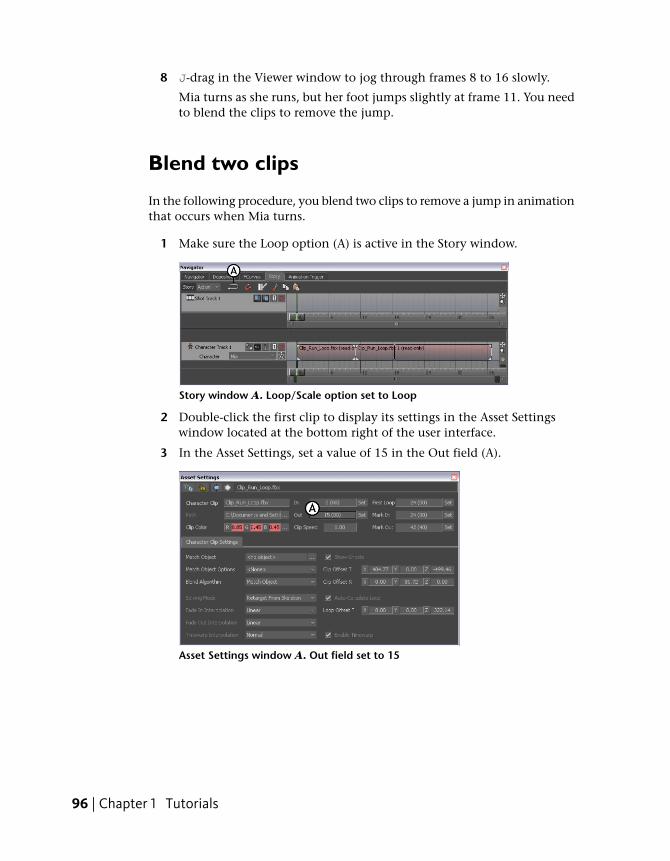
8 J-drag in the Viewer window to jog through frames 8 to 16 slowly.
Mia turns as she runs, but her foot jumps slightly at frame 11. You needto blend the clips to remove the jump.
Blend two clips
In the following procedure, you blend two clips to remove a jump in animationthat occurs when Mia turns.
1 Make sure the Loop option (A) is active in the Story window.
Story window A. Loop/Scale option set to Loop
2 Double-click the first clip to display its settings in the Asset Settingswindow located at the bottom right of the user interface.
3 In the Asset Settings, set a value of 15 in the Out field (A).
Asset Settings window A. Out field set to 15
96 | Chapter 1 Tutorials
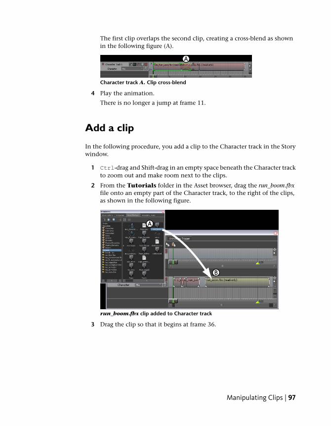
The first clip overlaps the second clip, creating a cross-blend as shownin the following figure (A).
Character track A. Clip cross-blend
4 Play the animation.
There is no longer a jump at frame 11.
Add a clip
In the following procedure, you add a clip to the Character track in the Storywindow.
1 Ctrl-drag and Shift-drag in an empty space beneath the Character trackto zoom out and make room next to the clips.
2 From the Tutorials folder in the Asset browser, drag the run_boom.fbxfile onto an empty part of the Character track, to the right of the clips,as shown in the following figure.
run_boom.fbx clip added to Character track
3 Drag the clip so that it begins at frame 36.
Manipulating Clips | 97
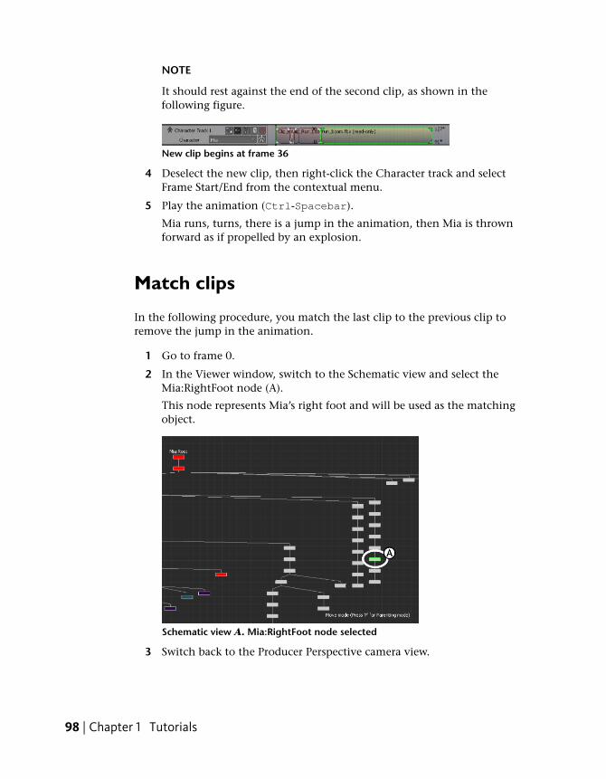
NOTE
It should rest against the end of the second clip, as shown in thefollowing figure.
New clip begins at frame 36
4 Deselect the new clip, then right-click the Character track and selectFrame Start/End from the contextual menu.
5 Play the animation (Ctrl-Spacebar).
Mia runs, turns, there is a jump in the animation, then Mia is thrownforward as if propelled by an explosion.
Match clips
In the following procedure, you match the last clip to the previous clip toremove the jump in the animation.
1 Go to frame 0.
2 In the Viewer window, switch to the Schematic view and select theMia:RightFoot node (A).
This node represents Mia’s right foot and will be used as the matchingobject.
Schematic view A. Mia:RightFoot node selected
3 Switch back to the Producer Perspective camera view.
98 | Chapter 1 Tutorials
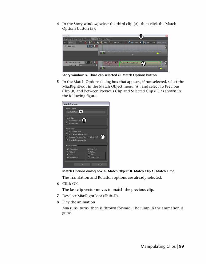
4 In the Story window, select the third clip (A), then click the MatchOptions button (B).
Story window A. Third clip selected B. Match Options button
5 In the Match Options dialog box that appears, if not selected, select theMia:RightFoot in the Match Object menu (A), and select To PreviousClip (B) and Between Previous Clip and Selected Clip (C) as shown inthe following figure.
Match Options dialog box A. Match Object B. Match Clip C. Match Time
The Translation and Rotation options are already selected.
6 Click OK.
The last clip vector moves to match the previous clip.
7 Deselect Mia:RightFoot (Shift-D).
8 Play the animation.
Mia runs, turns, then is thrown forward. The jump in the animation isgone.
Manipulating Clips | 99
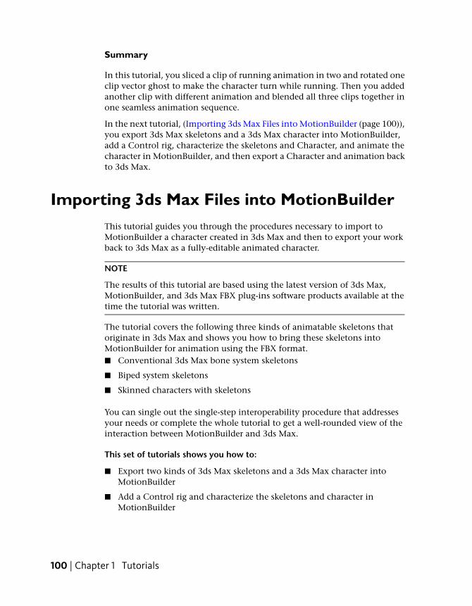
Summary
In this tutorial, you sliced a clip of running animation in two and rotated oneclip vector ghost to make the character turn while running. Then you addedanother clip with different animation and blended all three clips together inone seamless animation sequence.
In the next tutorial, (Importing 3ds Max Files into MotionBuilder (page 100)),you export 3ds Max skeletons and a 3ds Max character into MotionBuilder,add a Control rig, characterize the skeletons and Character, and animate thecharacter in MotionBuilder, and then export a Character and animation backto 3ds Max.
Importing 3ds Max Files into MotionBuilderThis tutorial guides you through the procedures necessary to import toMotionBuilder a character created in 3ds Max and then to export your workback to 3ds Max as a fully-editable animated character.
NOTE
The results of this tutorial are based using the latest version of 3ds Max,MotionBuilder, and 3ds Max FBX plug-ins software products available at thetime the tutorial was written.
The tutorial covers the following three kinds of animatable skeletons thatoriginate in 3ds Max and shows you how to bring these skeletons intoMotionBuilder for animation using the FBX format.■ Conventional 3ds Max bone system skeletons
■ Biped system skeletons
■ Skinned characters with skeletons
You can single out the single-step interoperability procedure that addressesyour needs or complete the whole tutorial to get a well-rounded view of theinteraction between MotionBuilder and 3ds Max.
This set of tutorials shows you how to:
■ Export two kinds of 3ds Max skeletons and a 3ds Max character intoMotionBuilder
■ Add a Control rig and characterize the skeletons and character inMotionBuilder
100 | Chapter 1 Tutorials
■ Animate the character in MotionBuilder and prepare it for import to 3dsMax
NOTE Although the procedures in this tutorial use the MotionBuilder keyboardshortcuts, you can use 3ds Max keyboard shortcuts in MotionBuilder if you selectSettings > Keyboard Configuration > 3ds Max from the MotionBuilder menu bar.See 3ds Max keyboard shortcuts.
Autodesk MotionBuilder’s default setting in the Time Format menu is 24frames per second (fps), where the default in 3ds Max is 30 fps. You can changethe frame rate for your output at any time, outputting the correct number offrames to maintain the correct playback speed for your animation.
For example, if you create a 90-frame animation for video, using an NTSCframe rate of 30 frames per second, the result will be three seconds ofanimation. If you later discover you need to output to PAL video (at 25 framesper second), you can switch to the PAL frame rate. The 90 frames areautomatically converted to 75, producing the same total animation time witha different number of frames. You can later switch back to NTSC frame rateto restore the original 90 frames of animation.
You can switch back and forth between frame rates at any time without losinganimation data. However, Autodesk MotionBuilder retains the last session’ssettings. Remember to revert back to 24 fps at the end of this tutorial if youwant to continue with any of the other tutorials.
Prepare for this tutorial
To complete this tutorial, you need the current versions of 3ds Max, andMotionBuilder installed on your system.
If you do not have the current version of 3ds Max, you can download a trialversion of the software product from the Autodesk web site at:http://www.autodesk.com/3dsmax.
You can choose to either complete the entire tutorial or parts of the tutorial.
The following assets are required for this tutorial:
■ skeletons.max
■ bone_skeleton.FBX
■ bone_skeleton_characterized.FBX
■ biped.FBX
Importing 3ds Max Files into MotionBuilder | 101
■ Pepe.max
■ Pepe.FBX
■ Pepe_rigged.FBX
■ IceSlip.fbx
■ Pepe_Mocap.FBX
■ Pepe_keyanim.FBX
■ Pepe_plotted.FBX
■ Pepe_plotted.max
You can find the tutorial assets in the MotionBuilder Asset browser’s Tutorialsfolder as well as in the Tutorials folder located in the MotionBuilder directoryon your system.
3ds Max skeletons
This tutorial shows you how to export a conventional 3ds Max bone systemskeleton data to FBX format, import to MotionBuilder, and then characterizeit so you can animate it.
You will need the following assets for this tutorial:
■ skeletons.max
■ bone_skeleton.FBX
■ bone_skeleton_characterized.FBX
Export and characterize a 3ds Max skeleton inMotionBuilder
In the following procedure, you export a conventional 3ds Max bone systemskeleton and use the 3ds Max Send To feature to open it in MotionBuilder foranimation.
NOTE This tutorial uses the MotionBuilder and 3ds Max 2012 single-stepinteroperability workflows, using the Send To menu option. If you do not havethe 2012 versions of these products, refer to the Exporting 3ds Max skeletons toMotionBuilder topic in the MotionBuilder documentation.
102 | Chapter 1 Tutorials
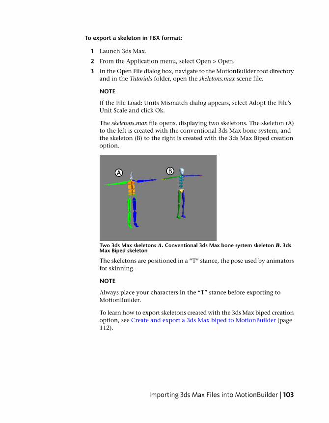
To export a skeleton in FBX format:
1 Launch 3ds Max.
2 From the Application menu, select Open > Open.
3 In the Open File dialog box, navigate to the MotionBuilder root directoryand in the Tutorials folder, open the skeletons.max scene file.
NOTE
If the File Load: Units Mismatch dialog appears, select Adopt the File’sUnit Scale and click Ok.
The skeletons.max file opens, displaying two skeletons. The skeleton (A)to the left is created with the conventional 3ds Max bone system, andthe skeleton (B) to the right is created with the 3ds Max Biped creationoption.
Two 3ds Max skeletons A. Conventional 3ds Max bone system skeleton B. 3dsMax Biped skeleton
The skeletons are positioned in a “T” stance, the pose used by animatorsfor skinning.
NOTE
Always place your characters in the “T” stance before exporting toMotionBuilder.
To learn how to export skeletons created with the 3ds Max biped creationoption, see Create and export a 3ds Max biped to MotionBuilder (page112).
Importing 3ds Max Files into MotionBuilder | 103
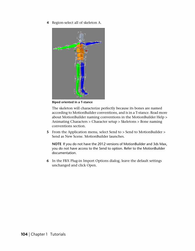
4 Region-select all of skeleton A.
Biped oriented in a T-stance
The skeleton will characterize perfectly because its bones are namedaccording to MotionBuilder conventions, and is in a T-stance. Read moreabout MotionBuilder naming conventions in the MotionBuilder Help >Animating Characters > Character setup > Skeletons > Bone namingconventions section.
5 From the Application menu, select Send to > Send to MotionBuilder >Send as New Scene. MotionBuilder launches.
NOTE If you do not have the 2012 versions of MotionBuilder and 3ds Max,you do not have access to the Send to option. Refer to the MotionBuilderdocumentation.
6 In the FBX Plug-in Import Options dialog, leave the default settingsunchanged and click Open.
104 | Chapter 1 Tutorials
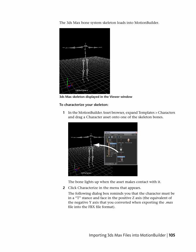
The 3ds Max bone system skeleton loads into MotionBuilder.
3ds Max skeleton displayed in the Viewer window
To characterize your skeleton:
1 In the MotionBuilder Asset browser, expand Templates > Charactersand drag a Character asset onto one of the skeleton bones.
The bone lights up when the asset makes contact with it.
2 Click Characterize in the menu that appears.
The following dialog box reminds you that the character must bein a “T” stance and face in the positive Z axis (the equivalent ofthe negative Y axis that you converted when exporting the .maxfile into the FBX file format).
Importing 3ds Max Files into MotionBuilder | 105
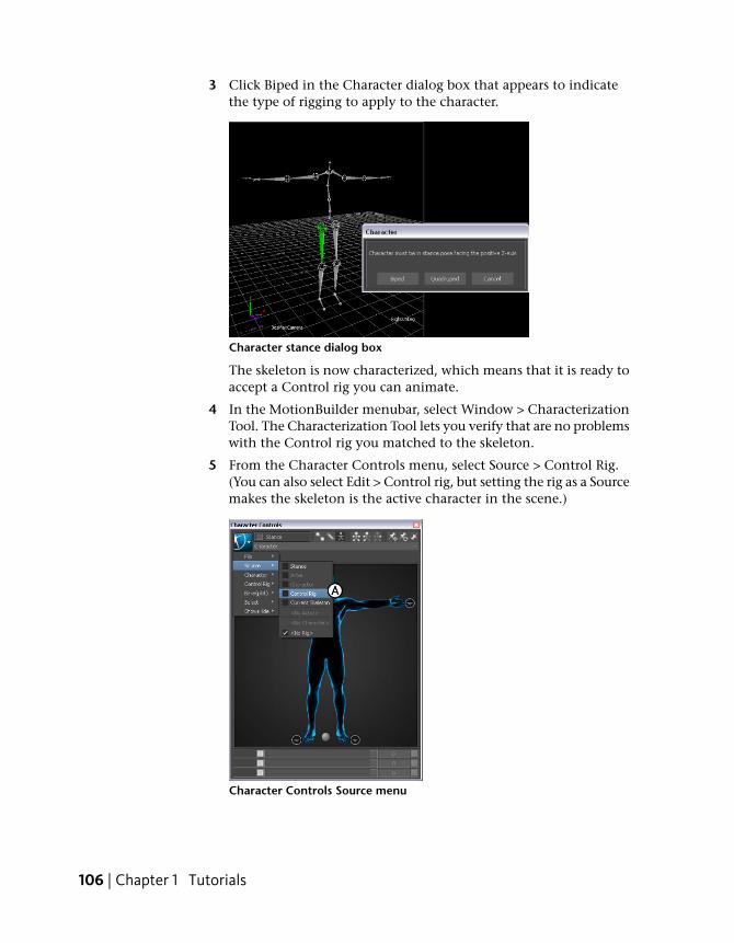
3 Click Biped in the Character dialog box that appears to indicatethe type of rigging to apply to the character.
Character stance dialog box
The skeleton is now characterized, which means that it is ready toaccept a Control rig you can animate.
4 In the MotionBuilder menubar, select Window > CharacterizationTool. The Characterization Tool lets you verify that are no problemswith the Control rig you matched to the skeleton.
5 From the Character Controls menu, select Source > Control Rig.(You can also select Edit > Control rig, but setting the rig as a Sourcemakes the skeleton is the active character in the scene.)
Character Controls Source menu
106 | Chapter 1 Tutorials
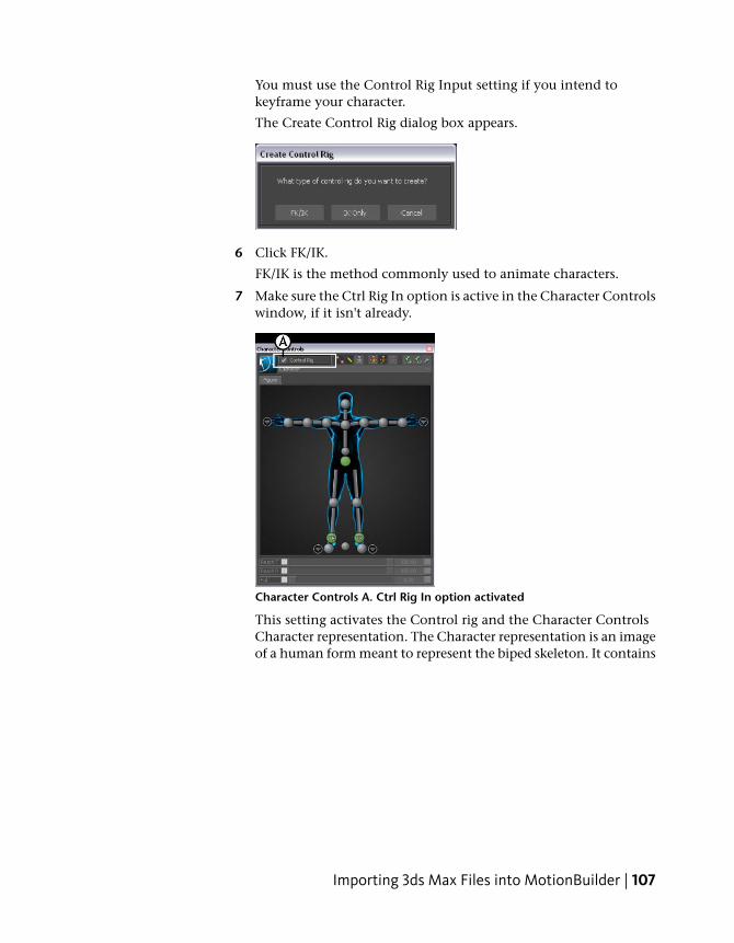
You must use the Control Rig Input setting if you intend tokeyframe your character.
The Create Control Rig dialog box appears.
6 Click FK/IK.
FK/IK is the method commonly used to animate characters.
7 Make sure the Ctrl Rig In option is active in the Character Controlswindow, if it isn't already.
Character Controls A. Ctrl Rig In option activated
This setting activates the Control rig and the Character ControlsCharacter representation. The Character representation is an imageof a human form meant to represent the biped skeleton. It contains
Importing 3ds Max Files into MotionBuilder | 107
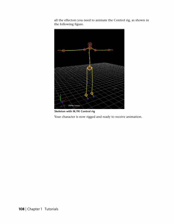
all the effectors you need to animate the Control rig, as shown inthe following figure.
Skeleton with IK/FK Control rig
Your character is now rigged and ready to receive animation.
108 | Chapter 1 Tutorials
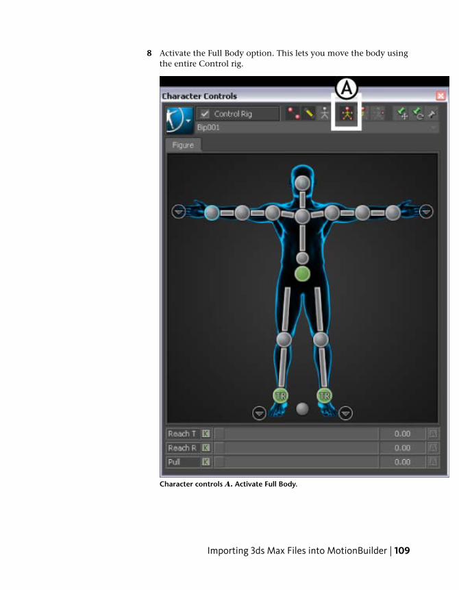
8 Activate the Full Body option. This lets you move the body usingthe entire Control rig.
Character controls A. Activate Full Body.
Importing 3ds Max Files into MotionBuilder | 109
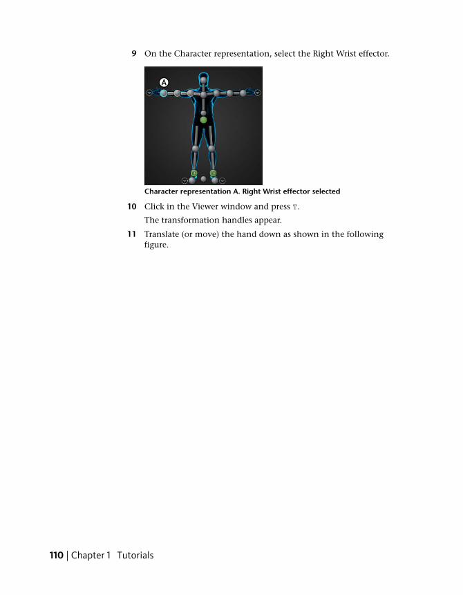
9 On the Character representation, select the Right Wrist effector.
Character representation A. Right Wrist effector selected
10 Click in the Viewer window and press T.
The transformation handles appear.
11 Translate (or move) the hand down as shown in the followingfigure.
110 | Chapter 1 Tutorials
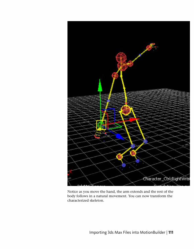
Notice as you move the hand, the arm extends and the rest of thebody follows in a natural movement. You can now transform thecharacterized skeleton.
Importing 3ds Max Files into MotionBuilder | 111
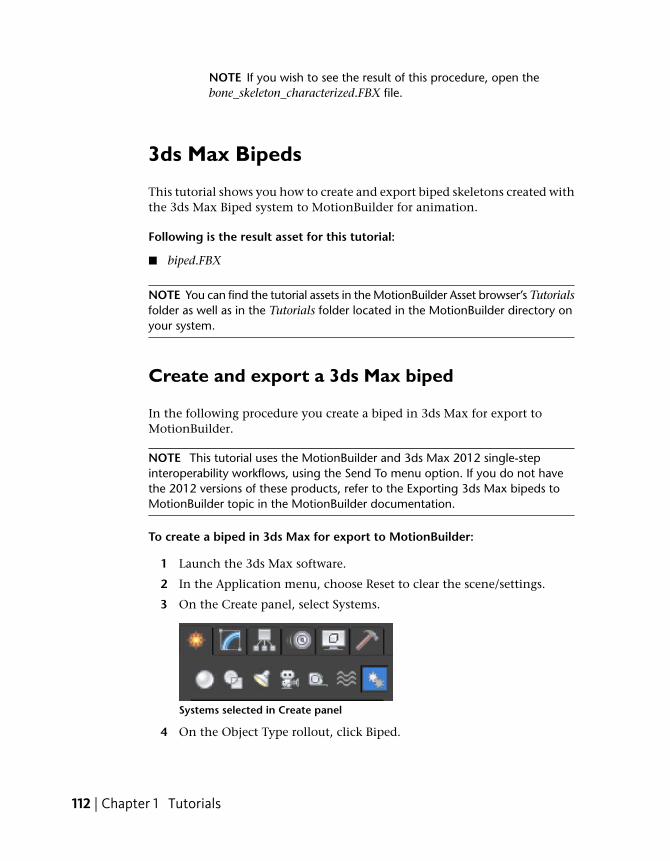
NOTE If you wish to see the result of this procedure, open thebone_skeleton_characterized.FBX file.
3ds Max Bipeds
This tutorial shows you how to create and export biped skeletons created withthe 3ds Max Biped system to MotionBuilder for animation.
Following is the result asset for this tutorial:
■ biped.FBX
NOTE You can find the tutorial assets in the MotionBuilder Asset browser’s Tutorialsfolder as well as in the Tutorials folder located in the MotionBuilder directory onyour system.
Create and export a 3ds Max biped
In the following procedure you create a biped in 3ds Max for export toMotionBuilder.
NOTE This tutorial uses the MotionBuilder and 3ds Max 2012 single-stepinteroperability workflows, using the Send To menu option. If you do not havethe 2012 versions of these products, refer to the Exporting 3ds Max bipeds toMotionBuilder topic in the MotionBuilder documentation.
To create a biped in 3ds Max for export to MotionBuilder:
1 Launch the 3ds Max software.
2 In the Application menu, choose Reset to clear the scene/settings.
3 On the Create panel, select Systems.
Systems selected in Create panel
4 On the Object Type rollout, click Biped.
112 | Chapter 1 Tutorials
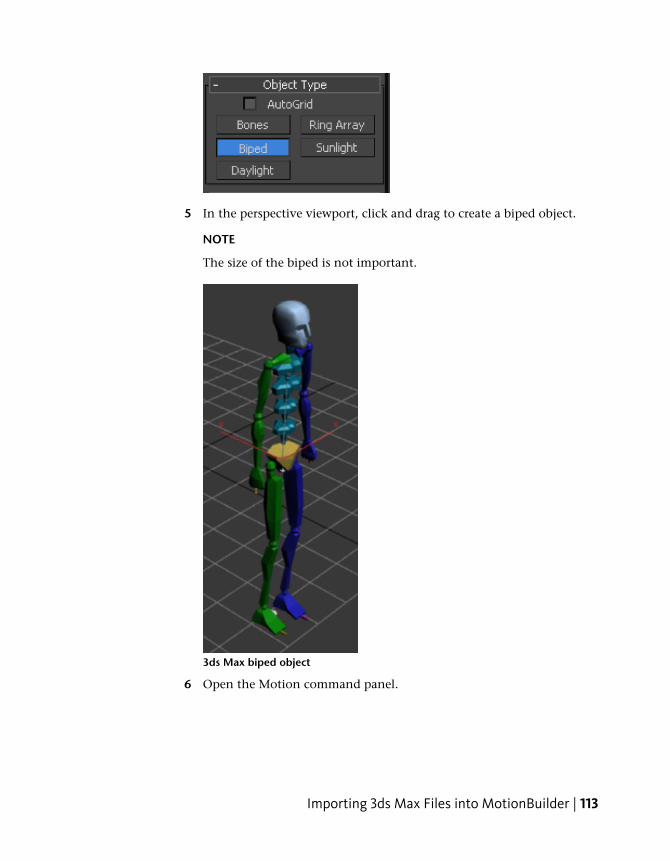
5 In the perspective viewport, click and drag to create a biped object.
NOTE
The size of the biped is not important.
3ds Max biped object
6 Open the Motion command panel.
Importing 3ds Max Files into MotionBuilder | 113
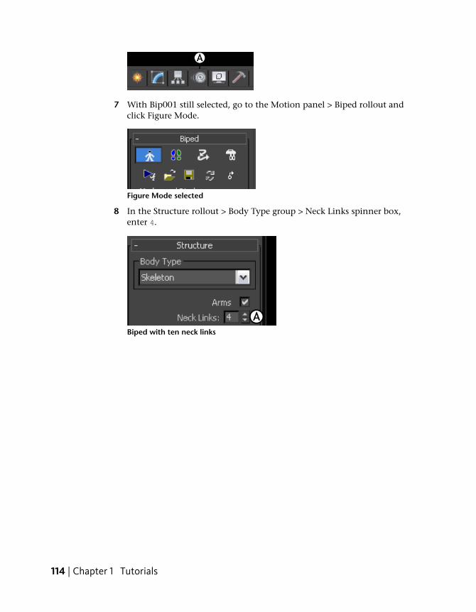
7 With Bip001 still selected, go to the Motion panel > Biped rollout andclick Figure Mode.
Figure Mode selected
8 In the Structure rollout > Body Type group > Neck Links spinner box,enter 4.
Biped with ten neck links
114 | Chapter 1 Tutorials
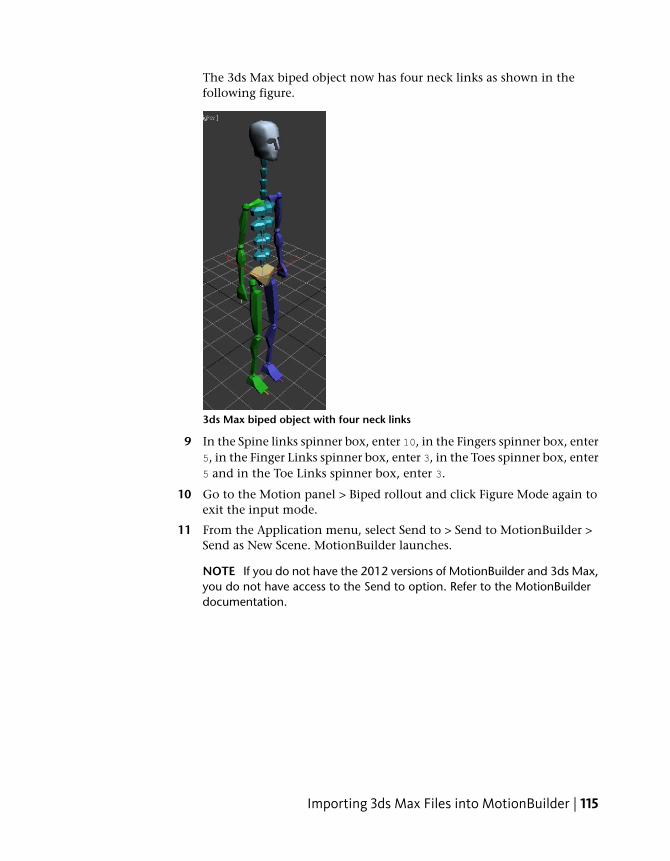
The 3ds Max biped object now has four neck links as shown in thefollowing figure.
3ds Max biped object with four neck links
9 In the Spine links spinner box, enter 10, in the Fingers spinner box, enter5, in the Finger Links spinner box, enter 3, in the Toes spinner box, enter5 and in the Toe Links spinner box, enter 3.
10 Go to the Motion panel > Biped rollout and click Figure Mode again toexit the input mode.
11 From the Application menu, select Send to > Send to MotionBuilder >Send as New Scene. MotionBuilder launches.
NOTE If you do not have the 2012 versions of MotionBuilder and 3ds Max,you do not have access to the Send to option. Refer to the MotionBuilderdocumentation.
Importing 3ds Max Files into MotionBuilder | 115
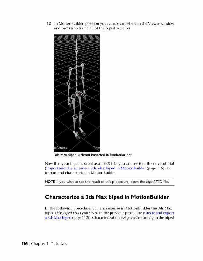
12 In MotionBuilder, position your cursor anywhere in the Viewer windowand press A to frame all of the biped skeleton.
3ds Max biped skeleton imported in MotionBuilder
Now that your biped is saved as an FBX file, you can use it in the next tutorial(Import and characterize a 3ds Max biped in MotionBuilder (page 116)) toimport and characterize in MotionBuilder.
NOTE If you wish to see the result of this procedure, open the biped.FBX file.
Characterize a 3ds Max biped in MotionBuilder
In the following procedure, you characterize in MotionBuilder the 3ds Maxbiped (My_biped.FBX) you saved in the previous procedure (Create and exporta 3ds Max biped (page 112)). Characterization assigns a Control rig to the biped
116 | Chapter 1 Tutorials
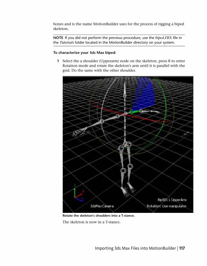
bones and is the name MotionBuilder uses for the process of rigging a bipedskeleton.
NOTE If you did not perform the previous procedure, use the biped.FBX file inthe Tutorials folder located in the MotionBuilder directory on your system.
To characterize your 3ds Max biped:
1 Select the a shoulder (Upperarm) node on the skeleton, press R to enterRotation mode and rotate the skeleton's arm until it is parallel with thegrid. Do the same with the other shoulder.
Rotate the skeleton's shoulders into a T-stance.
The skeleton is now in a T-stance.
Importing 3ds Max Files into MotionBuilder | 117
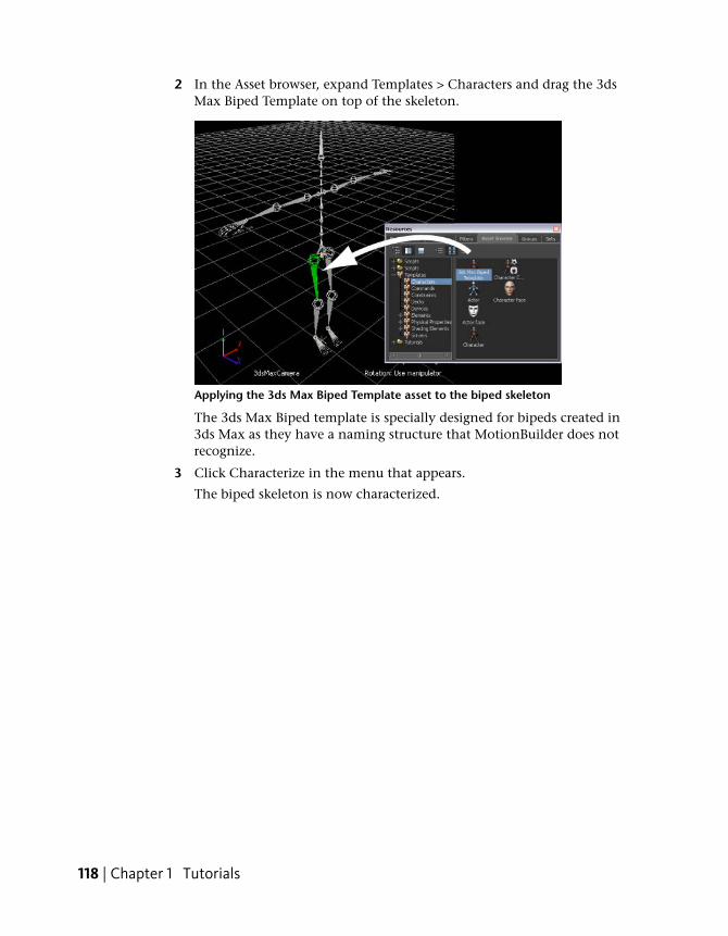
2 In the Asset browser, expand Templates > Characters and drag the 3dsMax Biped Template on top of the skeleton.
Applying the 3ds Max Biped Template asset to the biped skeleton
The 3ds Max Biped template is specially designed for bipeds created in3ds Max as they have a naming structure that MotionBuilder does notrecognize.
3 Click Characterize in the menu that appears.
The biped skeleton is now characterized.
118 | Chapter 1 Tutorials
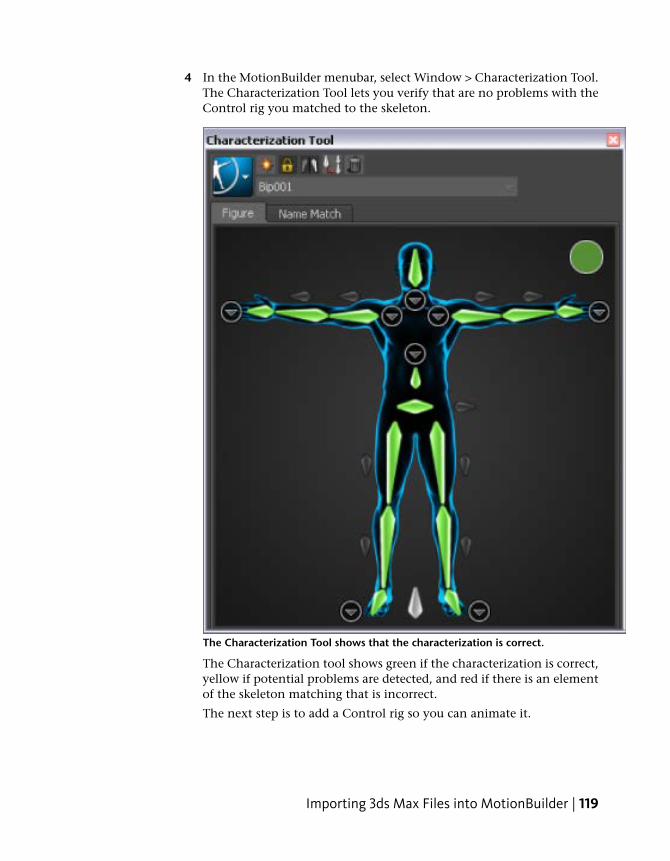
4 In the MotionBuilder menubar, select Window > Characterization Tool.The Characterization Tool lets you verify that are no problems with theControl rig you matched to the skeleton.
The Characterization Tool shows that the characterization is correct.
The Characterization tool shows green if the characterization is correct,yellow if potential problems are detected, and red if there is an elementof the skeleton matching that is incorrect.
The next step is to add a Control rig so you can animate it.
Importing 3ds Max Files into MotionBuilder | 119
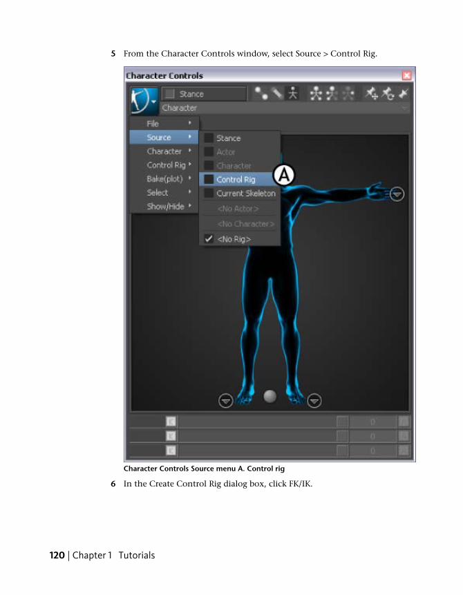
5 From the Character Controls window, select Source > Control Rig.
Character Controls Source menu A. Control rig
6 In the Create Control Rig dialog box, click FK/IK.
120 | Chapter 1 Tutorials
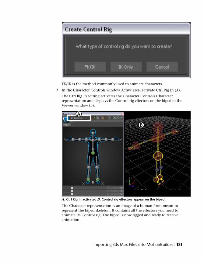
FK/IK is the method commonly used to animate characters.
7 In the Character Controls window Active area, activate Ctrl Rig In (A).
The Ctrl Rig In setting activates the Character Controls Characterrepresentation and displays the Control rig effectors on the biped in theViewer window (B).
A. Ctrl Rig In activated B. Control rig effectors appear on the biped
The Character representation is an image of a human form meant torepresent the biped skeleton. It contains all the effectors you need toanimate its Control rig. The biped is now rigged and ready to receiveanimation.
Importing 3ds Max Files into MotionBuilder | 121
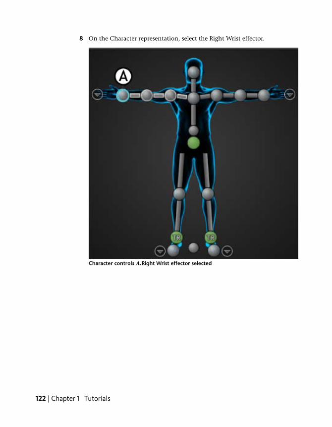
8 On the Character representation, select the Right Wrist effector.
Character controls A.Right Wrist effector selected
122 | Chapter 1 Tutorials
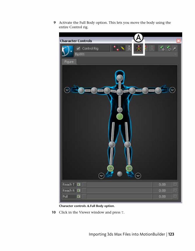
9 Activate the Full Body option. This lets you move the body using theentire Control rig.
Character controls A.Full Body option.
10 Click in the Viewer window and press T.
Importing 3ds Max Files into MotionBuilder | 123
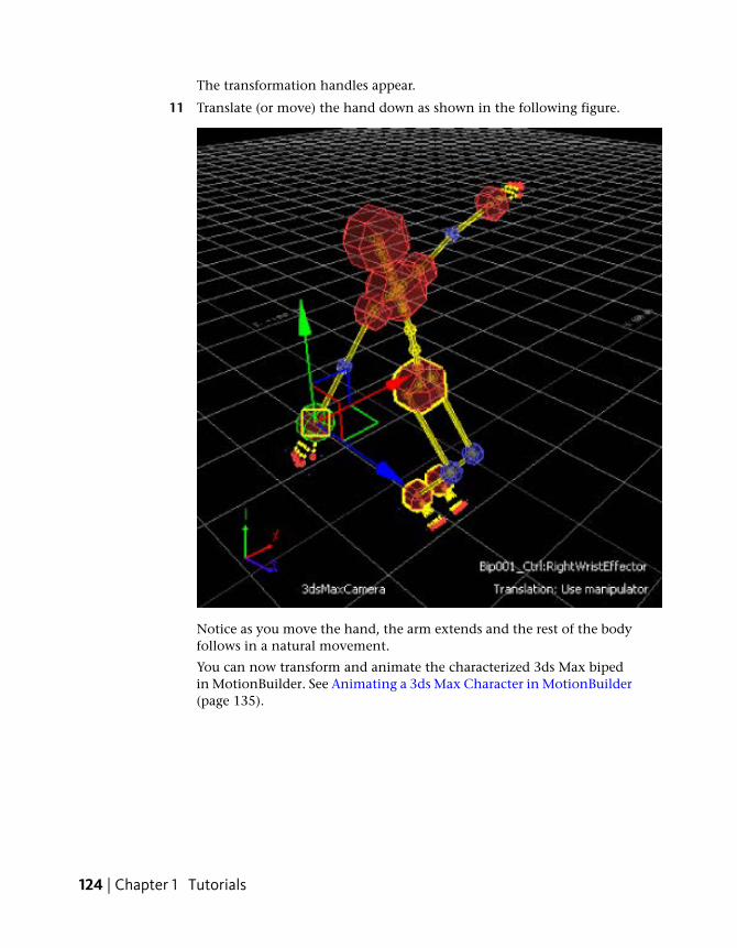
The transformation handles appear.
11 Translate (or move) the hand down as shown in the following figure.
Notice as you move the hand, the arm extends and the rest of the bodyfollows in a natural movement.
You can now transform and animate the characterized 3ds Max bipedin MotionBuilder. See Animating a 3ds Max Character in MotionBuilder(page 135).
124 | Chapter 1 Tutorials
3ds Max Characters
The following tutorial shows you how to export a character with a skeletoncreated and skinned in 3ds Max to the FBX file format, import toMotionBuilder, and then characterize it so you can animate it.
Since a character is a skeleton with skin and textures, the procedure is similarto the procedure shown in the tutorials for exporting 3ds Max skeletons andbiped skeletons.
Following is the asset required for this tutorial:
■ Pepe.max
Following are the result assets for this tutorial:
■ Pepe.FBX
■ Pepe_rigged.FBX
NOTE You can find the tutorial assets in the MotionBuilder Asset browser’s Tutorialsfolder as well as in the Tutorials folder located in the MotionBuilder directory onyour system.
Export a 3ds Max character
The following procedure shows you how to export a 3ds Max character toMotionBuilder.
NOTE This tutorial uses the MotionBuilder and 3ds Max 2012 single-stepinteroperability workflows, using the Send To menu option. If you do not havethe 2012 versions of these products, refer to the Export a 3ds Max character (page125) topic in the MotionBuilder documentation.
To export the 3ds Max Pepe character:
1 Launch the 3ds Max software.
2 In the Application menu, choose Reset to clear the scene/settings.
3 Select Open and open the Pepe.max scene file located in theMotionBuilder root directory under the Tutorials folder.
Importing 3ds Max Files into MotionBuilder | 125
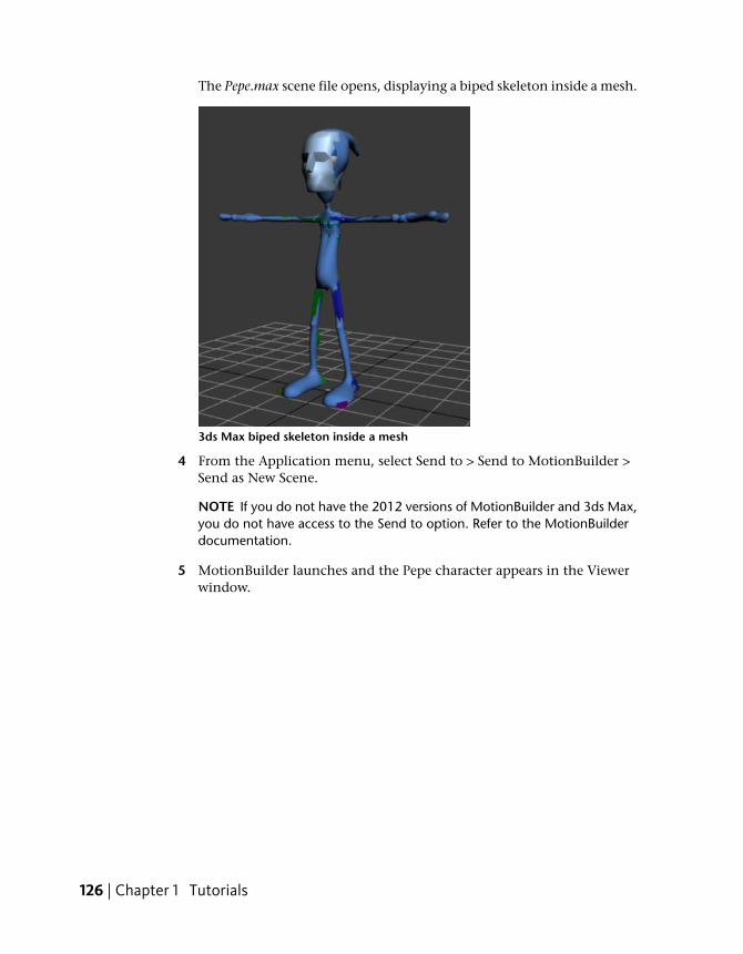
The Pepe.max scene file opens, displaying a biped skeleton inside a mesh.
3ds Max biped skeleton inside a mesh
4 From the Application menu, select Send to > Send to MotionBuilder >Send as New Scene.
NOTE If you do not have the 2012 versions of MotionBuilder and 3ds Max,you do not have access to the Send to option. Refer to the MotionBuilderdocumentation.
5 MotionBuilder launches and the Pepe character appears in the Viewerwindow.
126 | Chapter 1 Tutorials
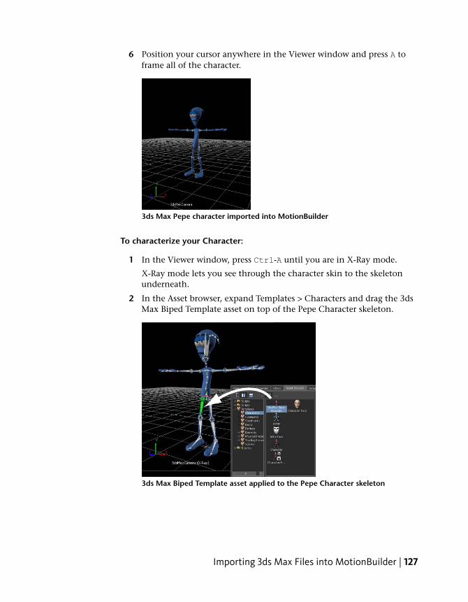
6 Position your cursor anywhere in the Viewer window and press A toframe all of the character.
3ds Max Pepe character imported into MotionBuilder
To characterize your Character:
1 In the Viewer window, press Ctrl-A until you are in X-Ray mode.
X-Ray mode lets you see through the character skin to the skeletonunderneath.
2 In the Asset browser, expand Templates > Characters and drag the 3dsMax Biped Template asset on top of the Pepe Character skeleton.
3ds Max Biped Template asset applied to the Pepe Character skeleton
Importing 3ds Max Files into MotionBuilder | 127
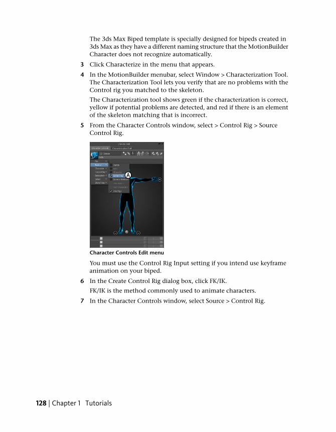
The 3ds Max Biped template is specially designed for bipeds created in3ds Max as they have a different naming structure that the MotionBuilderCharacter does not recognize automatically.
3 Click Characterize in the menu that appears.
4 In the MotionBuilder menubar, select Window > Characterization Tool.The Characterization Tool lets you verify that are no problems with theControl rig you matched to the skeleton.
The Characterization tool shows green if the characterization is correct,yellow if potential problems are detected, and red if there is an elementof the skeleton matching that is incorrect.
5 From the Character Controls window, select > Control Rig > SourceControl Rig.
Character Controls Edit menu
You must use the Control Rig Input setting if you intend use keyframeanimation on your biped.
6 In the Create Control Rig dialog box, click FK/IK.
FK/IK is the method commonly used to animate characters.
7 In the Character Controls window, select Source > Control Rig.
128 | Chapter 1 Tutorials
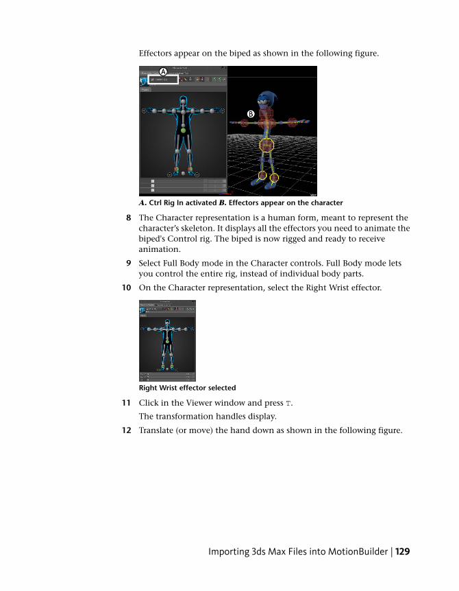
Effectors appear on the biped as shown in the following figure.
A. Ctrl Rig In activated B. Effectors appear on the character
8 The Character representation is a human form, meant to represent thecharacter’s skeleton. It displays all the effectors you need to animate thebiped's Control rig. The biped is now rigged and ready to receiveanimation.
9 Select Full Body mode in the Character controls. Full Body mode letsyou control the entire rig, instead of individual body parts.
10 On the Character representation, select the Right Wrist effector.
Right Wrist effector selected
11 Click in the Viewer window and press T.
The transformation handles display.
12 Translate (or move) the hand down as shown in the following figure.
Importing 3ds Max Files into MotionBuilder | 129
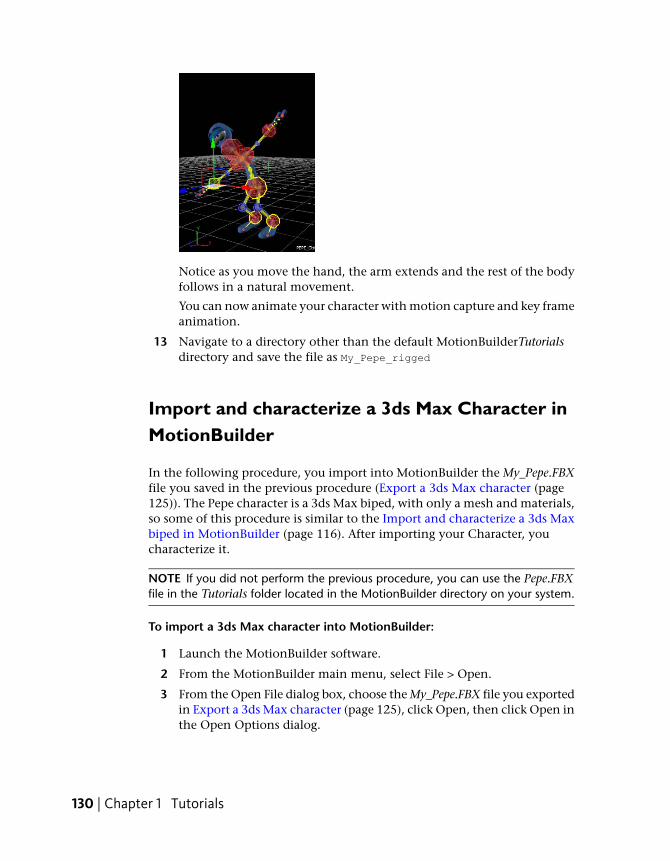
Notice as you move the hand, the arm extends and the rest of the bodyfollows in a natural movement.
You can now animate your character with motion capture and key frameanimation.
13 Navigate to a directory other than the default MotionBuilderTutorialsdirectory and save the file as My_Pepe_rigged
Import and characterize a 3ds Max Character inMotionBuilder
In the following procedure, you import into MotionBuilder the My_Pepe.FBXfile you saved in the previous procedure (Export a 3ds Max character (page125)). The Pepe character is a 3ds Max biped, with only a mesh and materials,so some of this procedure is similar to the Import and characterize a 3ds Maxbiped in MotionBuilder (page 116). After importing your Character, youcharacterize it.
NOTE If you did not perform the previous procedure, you can use the Pepe.FBXfile in the Tutorials folder located in the MotionBuilder directory on your system.
To import a 3ds Max character into MotionBuilder:
1 Launch the MotionBuilder software.
2 From the MotionBuilder main menu, select File > Open.
3 From the Open File dialog box, choose the My_Pepe.FBX file you exportedin Export a 3ds Max character (page 125), click Open, then click Open inthe Open Options dialog.
130 | Chapter 1 Tutorials
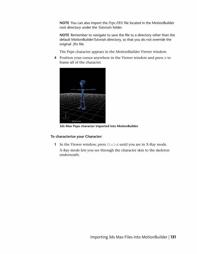
NOTE You can also import the Pepe.FBX file located in the MotionBuilderroot directory under the Tutorials folder.
NOTE Remember to navigate to save the file to a directory other than thedefault MotionBuilderTutorials directory, so that you do not override theoriginal .fbx file.
The Pepe character appears in the MotionBuilder Viewer window.
4 Position your cursor anywhere in the Viewer window and press A toframe all of the character.
3ds Max Pepe character imported into MotionBuilder
To characterize your Character:
1 In the Viewer window, press Ctrl-A until you are in X-Ray mode.
X-Ray mode lets you see through the character skin to the skeletonunderneath.
Importing 3ds Max Files into MotionBuilder | 131
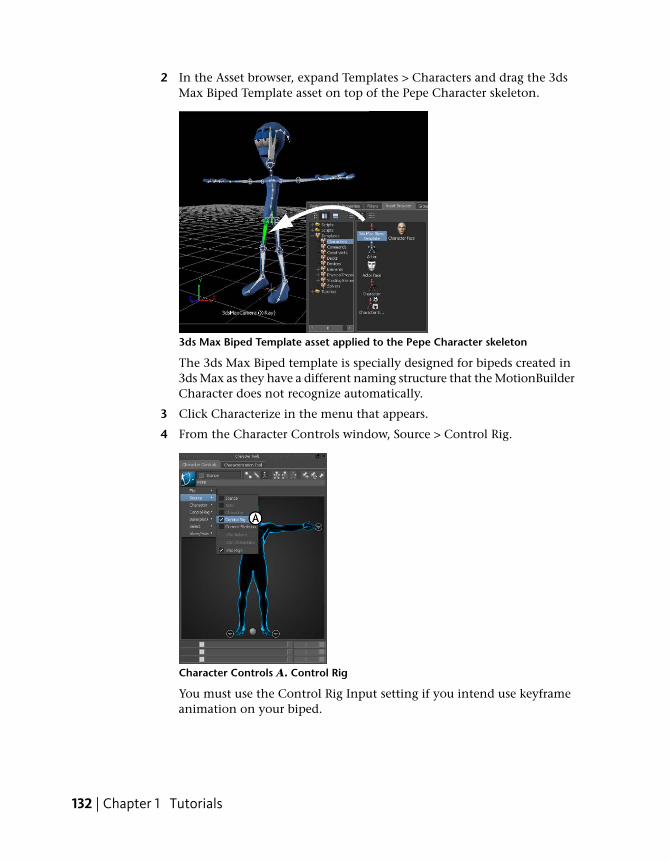
2 In the Asset browser, expand Templates > Characters and drag the 3dsMax Biped Template asset on top of the Pepe Character skeleton.
3ds Max Biped Template asset applied to the Pepe Character skeleton
The 3ds Max Biped template is specially designed for bipeds created in3ds Max as they have a different naming structure that the MotionBuilderCharacter does not recognize automatically.
3 Click Characterize in the menu that appears.
4 From the Character Controls window, Source > Control Rig.
Character Controls A. Control Rig
You must use the Control Rig Input setting if you intend use keyframeanimation on your biped.
132 | Chapter 1 Tutorials
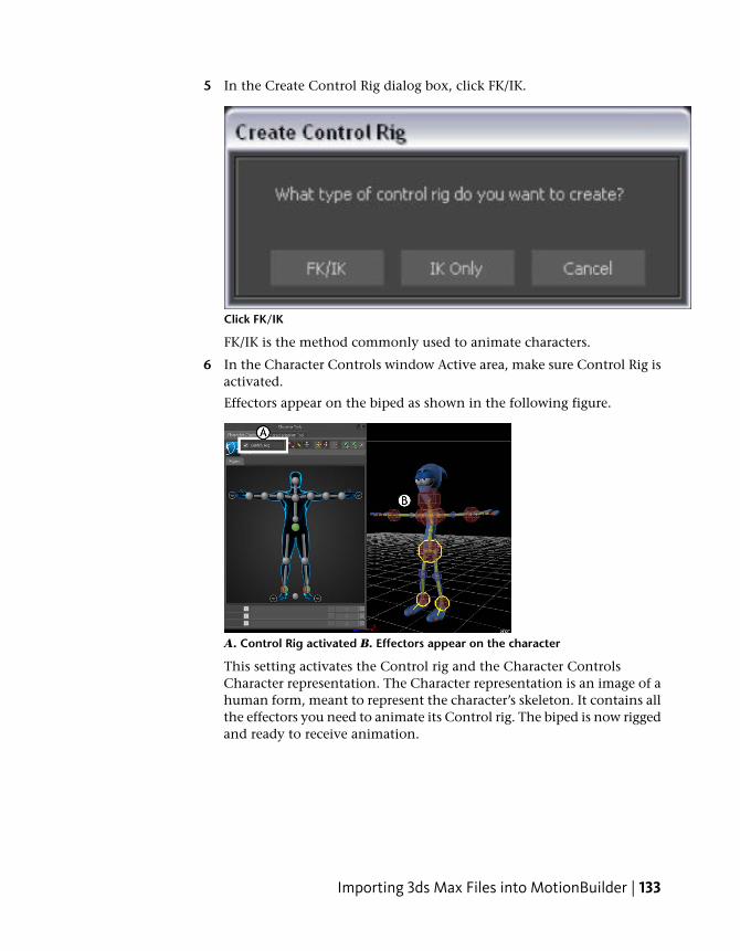
5 In the Create Control Rig dialog box, click FK/IK.
Click FK/IK
FK/IK is the method commonly used to animate characters.
6 In the Character Controls window Active area, make sure Control Rig isactivated.
Effectors appear on the biped as shown in the following figure.
A. Control Rig activated B. Effectors appear on the character
This setting activates the Control rig and the Character ControlsCharacter representation. The Character representation is an image of ahuman form, meant to represent the character’s skeleton. It contains allthe effectors you need to animate its Control rig. The biped is now riggedand ready to receive animation.
Importing 3ds Max Files into MotionBuilder | 133
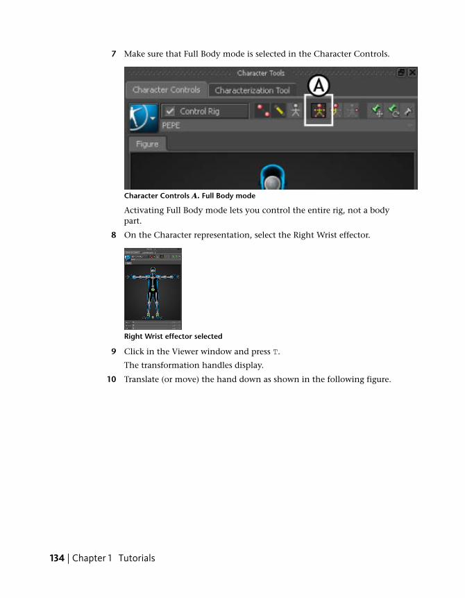
7 Make sure that Full Body mode is selected in the Character Controls.
Character Controls A. Full Body mode
Activating Full Body mode lets you control the entire rig, not a bodypart.
8 On the Character representation, select the Right Wrist effector.
Right Wrist effector selected
9 Click in the Viewer window and press T.
The transformation handles display.
10 Translate (or move) the hand down as shown in the following figure.
134 | Chapter 1 Tutorials
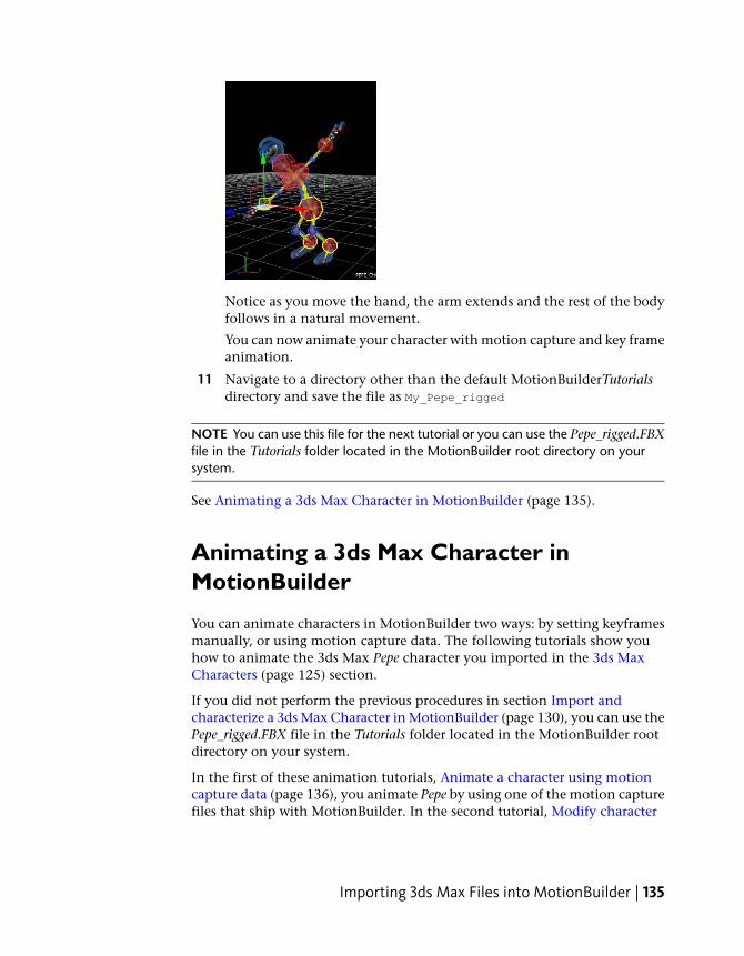
Notice as you move the hand, the arm extends and the rest of the bodyfollows in a natural movement.
You can now animate your character with motion capture and key frameanimation.
11 Navigate to a directory other than the default MotionBuilderTutorialsdirectory and save the file as My_Pepe_rigged
NOTE You can use this file for the next tutorial or you can use the Pepe_rigged.FBXfile in the Tutorials folder located in the MotionBuilder root directory on yoursystem.
See Animating a 3ds Max Character in MotionBuilder (page 135).
Animating a 3ds Max Character inMotionBuilder
You can animate characters in MotionBuilder two ways: by setting keyframesmanually, or using motion capture data. The following tutorials show youhow to animate the 3ds Max Pepe character you imported in the 3ds MaxCharacters (page 125) section.
If you did not perform the previous procedures in section Import andcharacterize a 3ds Max Character in MotionBuilder (page 130), you can use thePepe_rigged.FBX file in the Tutorials folder located in the MotionBuilder rootdirectory on your system.
In the first of these animation tutorials, Animate a character using motioncapture data (page 136), you animate Pepe by using one of the motion capturefiles that ship with MotionBuilder. In the second tutorial, Modify character
Importing 3ds Max Files into MotionBuilder | 135
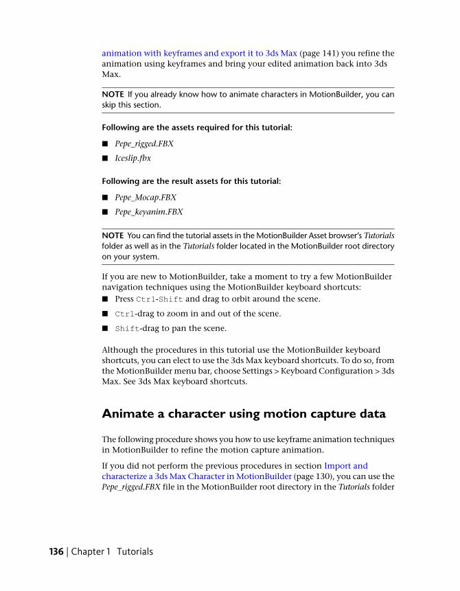
animation with keyframes and export it to 3ds Max (page 141) you refine theanimation using keyframes and bring your edited animation back into 3dsMax.
NOTE If you already know how to animate characters in MotionBuilder, you canskip this section.
Following are the assets required for this tutorial:
■ Pepe_rigged.FBX
■ Iceslip.fbx
Following are the result assets for this tutorial:
■ Pepe_Mocap.FBX
■ Pepe_keyanim.FBX
NOTE You can find the tutorial assets in the MotionBuilder Asset browser’s Tutorialsfolder as well as in the Tutorials folder located in the MotionBuilder root directoryon your system.
If you are new to MotionBuilder, take a moment to try a few MotionBuildernavigation techniques using the MotionBuilder keyboard shortcuts:■ Press Ctrl-Shift and drag to orbit around the scene.
■ Ctrl-drag to zoom in and out of the scene.
■ Shift-drag to pan the scene.
Although the procedures in this tutorial use the MotionBuilder keyboardshortcuts, you can elect to use the 3ds Max keyboard shortcuts. To do so, fromthe MotionBuilder menu bar, choose Settings > Keyboard Configuration > 3dsMax. See 3ds Max keyboard shortcuts.
Animate a character using motion capture data
The following procedure shows you how to use keyframe animation techniquesin MotionBuilder to refine the motion capture animation.
If you did not perform the previous procedures in section Import andcharacterize a 3ds Max Character in MotionBuilder (page 130), you can use thePepe_rigged.FBX file in the MotionBuilder root directory in the Tutorials folder
136 | Chapter 1 Tutorials
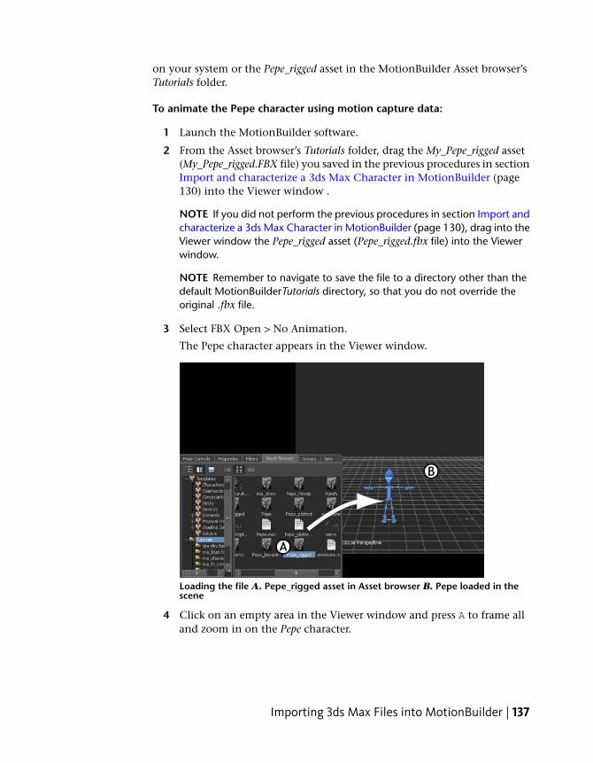
on your system or the Pepe_rigged asset in the MotionBuilder Asset browser’sTutorials folder.
To animate the Pepe character using motion capture data:
1 Launch the MotionBuilder software.
2 From the Asset browser’s Tutorials folder, drag the My_Pepe_rigged asset(My_Pepe_rigged.FBX file) you saved in the previous procedures in sectionImport and characterize a 3ds Max Character in MotionBuilder (page130) into the Viewer window .
NOTE If you did not perform the previous procedures in section Import andcharacterize a 3ds Max Character in MotionBuilder (page 130), drag into theViewer window the Pepe_rigged asset (Pepe_rigged.fbx file) into the Viewerwindow.
NOTE Remember to navigate to save the file to a directory other than thedefault MotionBuilderTutorials directory, so that you do not override theoriginal .fbx file.
3 Select FBX Open > No Animation.
The Pepe character appears in the Viewer window.
Loading the file A. Pepe_rigged asset in Asset browser B. Pepe loaded in thescene
4 Click on an empty area in the Viewer window and press A to frame alland zoom in on the Pepe character.
Importing 3ds Max Files into MotionBuilder | 137
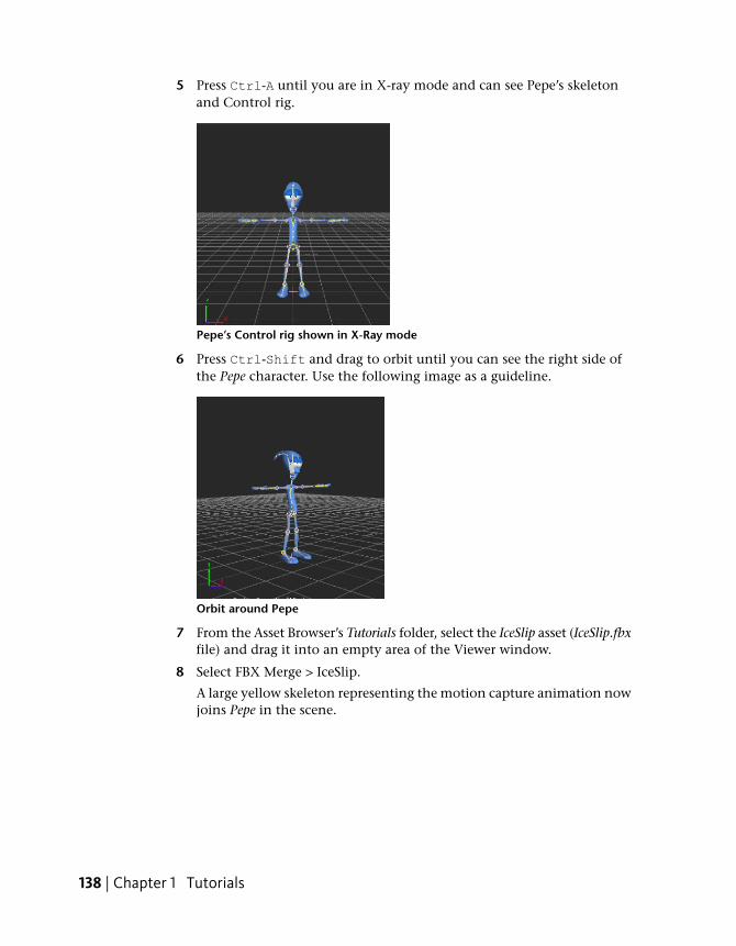
5 Press Ctrl-A until you are in X-ray mode and can see Pepe’s skeletonand Control rig.
Pepe’s Control rig shown in X-Ray mode
6 Press Ctrl-Shift and drag to orbit until you can see the right side ofthe Pepe character. Use the following image as a guideline.
Orbit around Pepe
7 From the Asset Browser’s Tutorials folder, select the IceSlip asset (IceSlip.fbxfile) and drag it into an empty area of the Viewer window.
8 Select FBX Merge > IceSlip.
A large yellow skeleton representing the motion capture animation nowjoins Pepe in the scene.
138 | Chapter 1 Tutorials
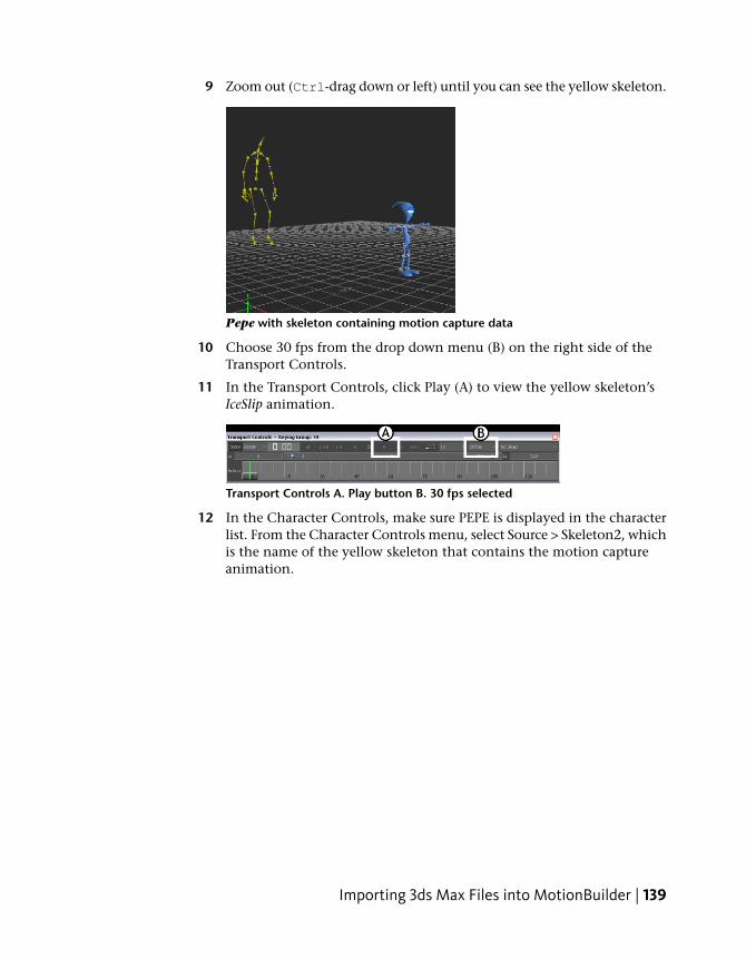
9 Zoom out (Ctrl-drag down or left) until you can see the yellow skeleton.
Pepe with skeleton containing motion capture data
10 Choose 30 fps from the drop down menu (B) on the right side of theTransport Controls.
11 In the Transport Controls, click Play (A) to view the yellow skeleton’sIceSlip animation.
Transport Controls A. Play button B. 30 fps selected
12 In the Character Controls, make sure PEPE is displayed in the characterlist. From the Character Controls menu, select Source > Skeleton2, whichis the name of the yellow skeleton that contains the motion captureanimation.
Importing 3ds Max Files into MotionBuilder | 139
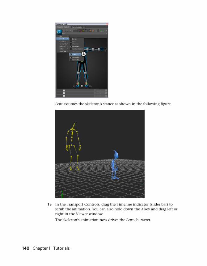
Pepe assumes the skeleton’s stance as shown in the following figure.
13 In the Transport Controls, drag the Timeline indicator (slider bar) toscrub the animation. You can also hold down the J key and drag left orright in the Viewer window.
The skeleton’s animation now drives the Pepe character.
140 | Chapter 1 Tutorials
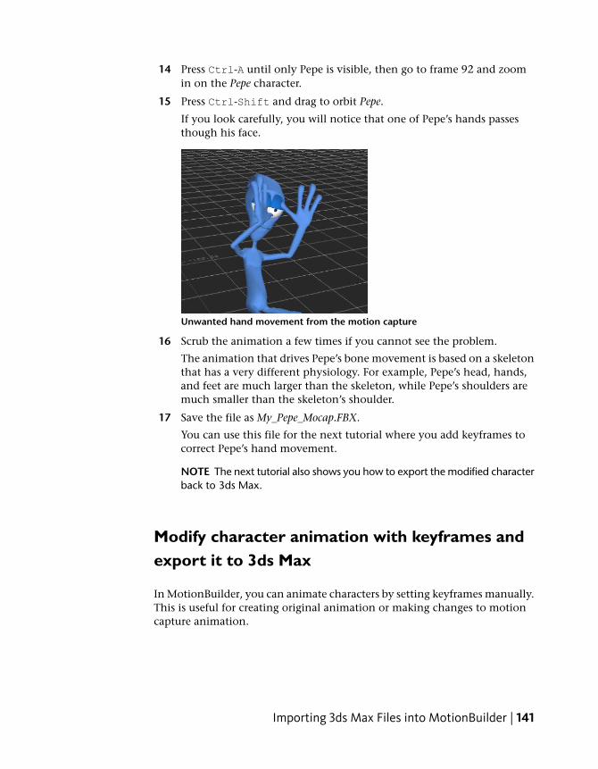
14 Press Ctrl-A until only Pepe is visible, then go to frame 92 and zoomin on the Pepe character.
15 Press Ctrl-Shift and drag to orbit Pepe.
If you look carefully, you will notice that one of Pepe’s hands passesthough his face.
Unwanted hand movement from the motion capture
16 Scrub the animation a few times if you cannot see the problem.
The animation that drives Pepe’s bone movement is based on a skeletonthat has a very different physiology. For example, Pepe’s head, hands,and feet are much larger than the skeleton, while Pepe’s shoulders aremuch smaller than the skeleton’s shoulder.
17 Save the file as My_Pepe_Mocap.FBX.
You can use this file for the next tutorial where you add keyframes tocorrect Pepe’s hand movement.
NOTE The next tutorial also shows you how to export the modified characterback to 3ds Max.
Modify character animation with keyframes andexport it to 3ds Max
In MotionBuilder, you can animate characters by setting keyframes manually.This is useful for creating original animation or making changes to motioncapture animation.
Importing 3ds Max Files into MotionBuilder | 141
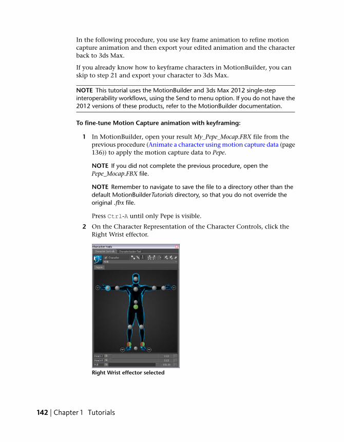
In the following procedure, you use key frame animation to refine motioncapture animation and then export your edited animation and the characterback to 3ds Max.
If you already know how to keyframe characters in MotionBuilder, you canskip to step 21 and export your character to 3ds Max.
NOTE This tutorial uses the MotionBuilder and 3ds Max 2012 single-stepinteroperability workflows, using the Send to menu option. If you do not have the2012 versions of these products, refer to the MotionBuilder documentation.
To fine-tune Motion Capture animation with keyframing:
1 In MotionBuilder, open your result My_Pepe_Mocap.FBX file from theprevious procedure (Animate a character using motion capture data (page136)) to apply the motion capture data to Pepe.
NOTE If you did not complete the previous procedure, open thePepe_Mocap.FBX file.
NOTE Remember to navigate to save the file to a directory other than thedefault MotionBuilderTutorials directory, so that you do not override theoriginal .fbx file.
Press Ctrl-A until only Pepe is visible.
2 On the Character Representation of the Character Controls, click theRight Wrist effector.
Right Wrist effector selected
142 | Chapter 1 Tutorials
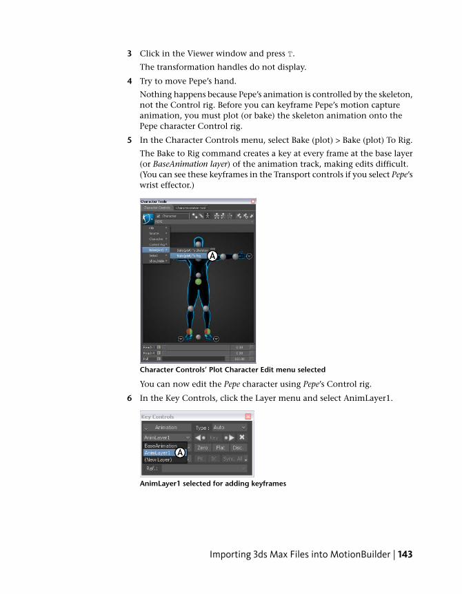
3 Click in the Viewer window and press T.
The transformation handles do not display.
4 Try to move Pepe’s hand.
Nothing happens because Pepe’s animation is controlled by the skeleton,not the Control rig. Before you can keyframe Pepe’s motion captureanimation, you must plot (or bake) the skeleton animation onto thePepe character Control rig.
5 In the Character Controls menu, select Bake (plot) > Bake (plot) To Rig.
The Bake to Rig command creates a key at every frame at the base layer(or BaseAnimation layer) of the animation track, making edits difficult.(You can see these keyframes in the Transport controls if you select Pepe’swrist effector.)
Character Controls’ Plot Character Edit menu selected
You can now edit the Pepe character using Pepe’s Control rig.
6 In the Key Controls, click the Layer menu and select AnimLayer1.
AnimLayer1 selected for adding keyframes
Importing 3ds Max Files into MotionBuilder | 143
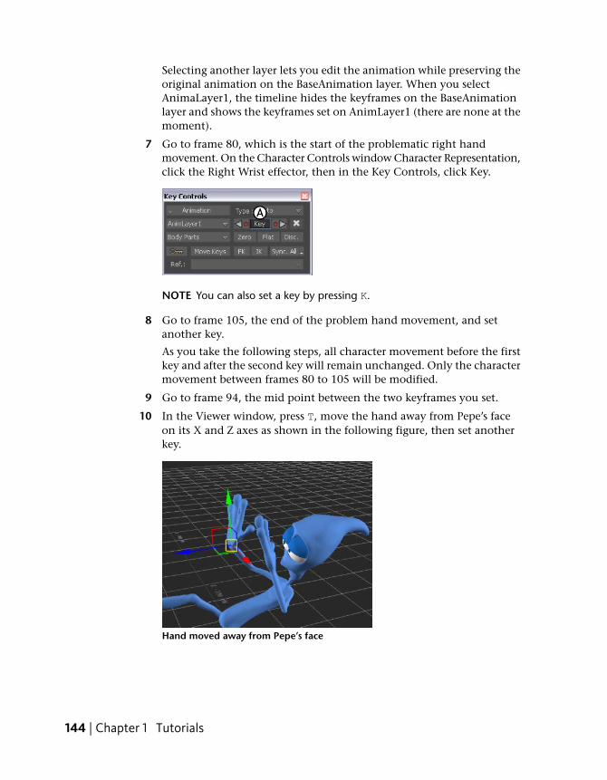
Selecting another layer lets you edit the animation while preserving theoriginal animation on the BaseAnimation layer. When you selectAnimaLayer1, the timeline hides the keyframes on the BaseAnimationlayer and shows the keyframes set on AnimLayer1 (there are none at themoment).
7 Go to frame 80, which is the start of the problematic right handmovement. On the Character Controls window Character Representation,click the Right Wrist effector, then in the Key Controls, click Key.
NOTE You can also set a key by pressing K.
8 Go to frame 105, the end of the problem hand movement, and setanother key.
As you take the following steps, all character movement before the firstkey and after the second key will remain unchanged. Only the charactermovement between frames 80 to 105 will be modified.
9 Go to frame 94, the mid point between the two keyframes you set.
10 In the Viewer window, press T, move the hand away from Pepe’s faceon its X and Z axes as shown in the following figure, then set anotherkey.
Hand moved away from Pepe’s face
144 | Chapter 1 Tutorials
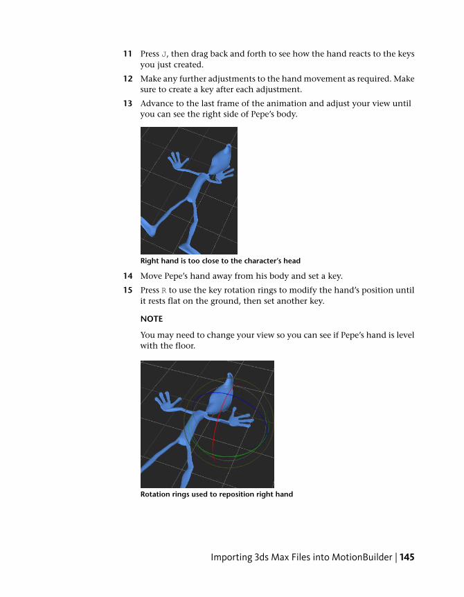
11 Press J, then drag back and forth to see how the hand reacts to the keysyou just created.
12 Make any further adjustments to the hand movement as required. Makesure to create a key after each adjustment.
13 Advance to the last frame of the animation and adjust your view untilyou can see the right side of Pepe’s body.
Right hand is too close to the character’s head
14 Move Pepe’s hand away from his body and set a key.
15 Press R to use the key rotation rings to modify the hand’s position untilit rests flat on the ground, then set another key.
NOTE
You may need to change your view so you can see if Pepe’s hand is levelwith the floor.
Rotation rings used to reposition right hand
Importing 3ds Max Files into MotionBuilder | 145
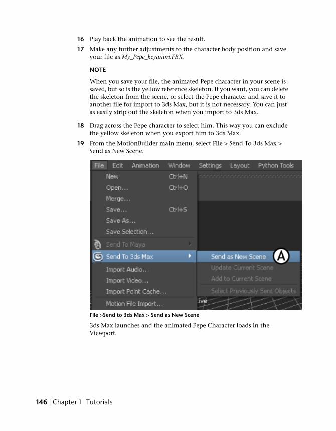
16 Play back the animation to see the result.
17 Make any further adjustments to the character body position and saveyour file as My_Pepe_keyanim.FBX.
NOTE
When you save your file, the animated Pepe character in your scene issaved, but so is the yellow reference skeleton. If you want, you can deletethe skeleton from the scene, or select the Pepe character and save it toanother file for import to 3ds Max, but it is not necessary. You can justas easily strip out the skeleton when you import to 3ds Max.
18 Drag across the Pepe character to select him. This way you can excludethe yellow skeleton when you export him to 3ds Max.
19 From the MotionBuilder main menu, select File > Send To 3ds Max >Send as New Scene.
File >Send to 3ds Max > Send as New Scene
3ds Max launches and the animated Pepe Character loads in theViewport.
146 | Chapter 1 Tutorials
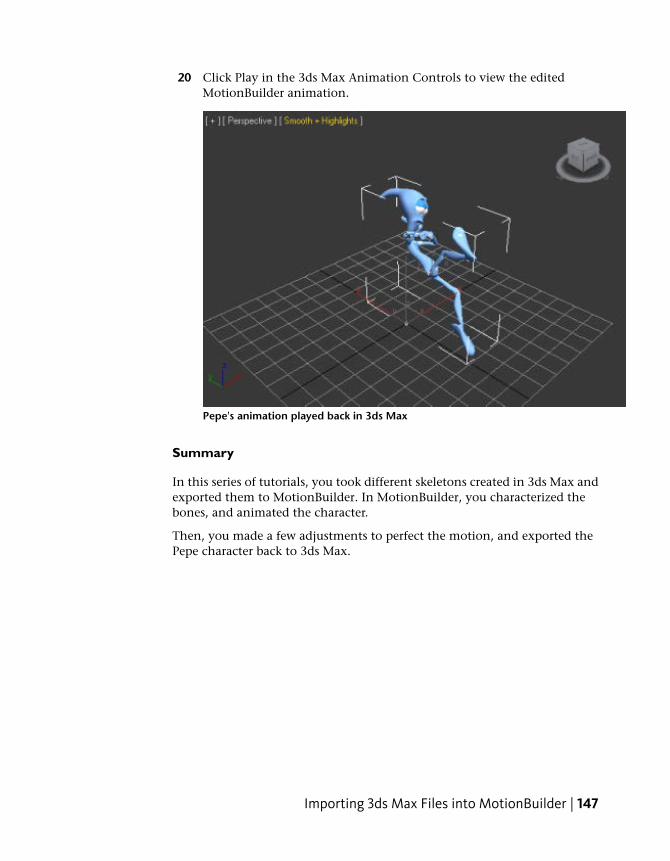
20 Click Play in the 3ds Max Animation Controls to view the editedMotionBuilder animation.
Pepe's animation played back in 3ds Max
Summary
In this series of tutorials, you took different skeletons created in 3ds Max andexported them to MotionBuilder. In MotionBuilder, you characterized thebones, and animated the character.
Then, you made a few adjustments to perfect the motion, and exported thePepe character back to 3ds Max.
Importing 3ds Max Files into MotionBuilder | 147