Embed Size (px)
Citation preview
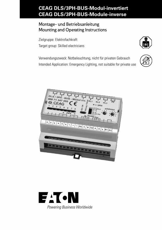
CEAG DLS/3PH-BUS-Modul-invertiertCEAG DLS/3PH-BUS-Module-inverse
Montage- und Betriebsanleitung Mounting and Operating Instructions
Zielgruppe: Elektrofachkraft
Target group: Skilled electricians
Verwendungszweck: Notbeleuchtung, nicht für privaten Gebrauch
Intended Application: Emergency Lighting, not suitable for private use
2 Manual CEAG DLS/3PH-BUS-Module-inverse 40071860006 July 2016 www.ceag.de
Inhaltsverzeichnis
Inhaltsverzeichnis
1 Normenkonformität . . . . . . . . . . . . . . . . . . . . . . . . . . . . . . . . . . . . . . . . . . . . . . . . . . . . . .3
2 Technische Daten . . . . . . . . . . . . . . . . . . . . . . . . . . . . . . . . . . . . . . . . . . . . . . . . . . . . . . . . . 4
3 Beschreibung/Verwendungsbereich . . . . . . . . . . . . . . . . . . . . . . . . . . . . . . . . . . . . . . . . . .4
4 Installation . . . . . . . . . . . . . . . . . . . . . . . . . . . . . . . . . . . . . . . . . . . . . . . . . . . . . . . . . . . . . .5
5 Montage . . . . . . . . . . . . . . . . . . . . . . . . . . . . . . . . . . . . . . . . . . . . . . . . . . . . . . . . . . . . . . . .5
6 Funktionsweise . . . . . . . . . . . . . . . . . . . . . . . . . . . . . . . . . . . . . . . . . . . . . . . . . . . . . . . . . . .5
7 Adressierung . . . . . . . . . . . . . . . . . . . . . . . . . . . . . . . . . . . . . . . . . . . . . . . . . . . . . . . . . . . .6
8 Wartung / Instandhaltung . . . . . . . . . . . . . . . . . . . . . . . . . . . . . . . . . . . . . . . . . . . . . . . . . .7
9 Entsorgung / Recycling . . . . . . . . . . . . . . . . . . . . . . . . . . . . . . . . . . . . . . . . . . . . . . . . . . . .7
Index
1 Conformity with standards . . . . . . . . . . . . . . . . . . . . . . . . . . . . . . . . . . . . . . . . . . . . . . . . .3
2 Technical data . . . . . . . . . . . . . . . . . . . . . . . . . . . . . . . . . . . . . . . . . . . . . . . . . . . . . . . . . . . .4
3 Description/Scope of application . . . . . . . . . . . . . . . . . . . . . . . . . . . . . . . . . . . . . . . . . . . .4
4 Installation . . . . . . . . . . . . . . . . . . . . . . . . . . . . . . . . . . . . . . . . . . . . . . . . . . . . . . . . . . . . . .5
5 Assembly . . . . . . . . . . . . . . . . . . . . . . . . . . . . . . . . . . . . . . . . . . . . . . . . . . . . . . . . . . . . . . .5
6 . Principle of operation . . . . . . . . . . . . . . . . . . . . . . . . . . . . . . . . . . . . . . . . . . . . . . . . . . . . .5
7 . Addressing . . . . . . . . . . . . . . . . . . . . . . . . . . . . . . . . . . . . . . . . . . . . . . . . . . . . . . . . . . . . . .6
8 Servicing / Maintenance . . . . . . . . . . . . . . . . . . . . . . . . . . . . . . . . . . . . . . . . . . . . . . . . . . .7
9 Disposal / Recycling . . . . . . . . . . . . . . . . . . . . . . . . . . . . . . . . . . . . . . . . . . . . . . . . . . . . . . .7
3Manual CEAG DLS/3PH-BUS-Module-inverse 40071860006 July 2016 www.ceag.de
1 Normenkonformität
1 Normenkonformität
Konform mit: EMV-Richtlinie 89/336/EWG, Niederspannungsrichtlinie 73/236/EWG, EN 50081-1, EN 61000-6-2, EN 50178, Schaltschwellen gem. EN 60598-2-22, EN 50171 und VDE 0108.Gemäß DIN EN ISO 9001 entwickelt, gefertigt und geprüft.
1 Conformity with standardsConforms to: EN 60 598-1, EN 60 598-2-22 and DIN EN 1838. Developed, manufactured and tested in accor-dance with DIN EN ISO 9001.
SICHERHEITSHINWEISE
• Das elektronische Überwachungs-/Schalt-modul DLS/3PH -BUS-Modul invertiert ist bestim mungs gemäß in unbeschädigtem und einwandfreiem Zustand zu betreiben!
• Als Ersatz dürfen nur Originalteile von CEAG verwendet werden!
• Vor der ersten Inbetriebnahme muss das Gerät entsprechend den im Abschnitt Installation genannten Anweisungen ge-prüft werden!
• Bei Durchführung von Arbeiten am Gerät ist sicherzustellen, dass das Gerät span-nungs frei geschaltet ist! Beachten Sie dabei die unter schiedlichen Ver sorgungen des Geräts bei Normal- und Notbetrieb.
• Beachten Sie bei allen Ar beiten an dem Gerät die nationalen Sicherheits- und Unfallverhütungsvorschriften und die nachfolgenden Sicherheitshinweise in der Betriebsanleitung, die mit einem ver-sehen sind!
SAFETY INSTRUCTIONS • The electronic monitoring/switch module
DLS/3PH-bus-module invers shall only be used for its intended purpose and in undamaged and perfect condition!
• Only genuine CEAG spare parts may be used for replacement and repair
• Prior to its initial operation, the luminaire will have to be checked in line with the instructions (see installation sector)
• When working on the electronic device make sure that it is disconnected from the voltage! Pay attention to the different power supplies in mains or battery opera-tion.
• Observe the national safety rules and regulations to prevent accidents as well as the safety instructions included in these operating instruction marked with
4 Manual CEAG DLS/3PH-BUS-Module-inverse 40071860006 July 2016 www.ceag.de
2 Technische Daten
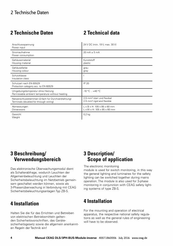
2 Technische Daten 2 Technical data
AnschlussspannungPower input
24 V DC (min. 19 V, max. 30 V)
StromaufnahmePower consumption
20 mA ± 5 mA
GehäusematerialHousing material
Kunststoff plastic
GehäusefarbeHousing colour
graugrey
SchutzklasseInsulation class
I
Schutzart nach EN 60529Protection category acc. to EN 60529
IP 20
Umgebungstemperatur ohne HeizungPermissable ambient temperature without heating
-10 °C .. +40 °C
Netzanschlussklemmen (2-fach für Durchverdrahtung)Terminals (doubled for through wiring)
2,5 mm² starr und flexibel 2.5 mm² rigid and flexible
Abmessungen Dimensions
L x B x H: 105 x 85 x 60 mmL x W x H: 105 x 85 x 60 mm
GewichtWeight
0,2 kg
3 Beschreibung/ Verwendungsbereich
Das elektronische Über wach ungs modul dient als Schalterabfrage, wodurch Leuchten der Allgemeinbeleuchtung und Leuchten der Sicherheitsbeleuchtung im Netzbetrieb gemein-sam geschaltet werden können, sowie als 3-Phasenüberwachung in Verbindung mit CEAG Sicherheitsbeleuchtungs anlagen Typ ZB-S.
4 Installation
Halten Sie die für das Errichten und Betreiben von elektrischen Be triebs mitteln gelten-den Sicher heits vorschriften, das Geräte -sicherheitsgesetz sowie die allgemein anerkannt-en Regeln der Technik ein!
3 Description/ Scope of application
The electronic monitoring module is used for switch monitoring, in this way the general lighting and luminaires for the safety lighting can be switched together during mains operation. The module is also used for 3-phase monitoring in conjunction with CEAG safety light-ing systems of type ZB-S.
4 Installation
For the mounting and operation of electrical apparatus, the respective national safety regula-tions as well as the general rules of engineering will have to be observed.
5Manual CEAG DLS/3PH-BUS-Module-inverse 40071860006 July 2016 www.ceag.de
5 Montage
5 Montage
Der Einbauort ist gemäß der einschlägi-gen Errichtungsnormen zu wählen (z.B. Unterverteilungen). Hierbei ist auf unzuläs-sige Temperaturen am Einbauort während des Betriebs zu achten.
6 Funktionsweise
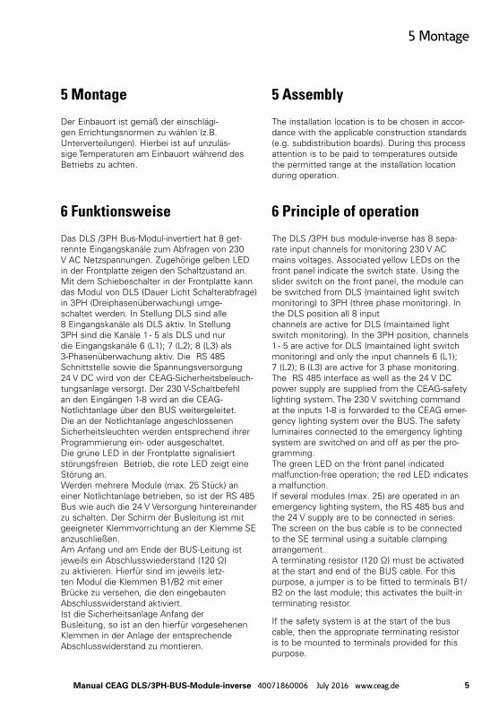
Das DLS /3PH Bus-Modul-invertiert hat 8 get-rennte Eingangskanäle zum Abfragen von 230 V AC Netzspannungen. Zugehörige gelben LED in der Frontplatte zeigen den Schaltzustand an. Mit dem Schiebeschalter in der Frontplatte kann das Modul von DLS (Dauer Licht Schalterabfrage) in 3PH (Dreiphasenüberwachung) umge-schaltet werden. In Stellung DLS sind alle 8 Eingangskanäle als DLS aktiv. In Stellung 3PH sind die Kanäle 1 - 5 als DLS und nur die Eingangskanäle 6 (L1); 7 (L2); 8 (L3) als 3-Phasenüberwachung aktiv. Die RS 485 Schnittstelle sowie die Spannungsversorgung 24 V DC wird von der CEAG-Sicherheitsbeleuch-tungs anlage versorgt. Der 230 V-Schaltbefehl an den Eingängen 1-8 wird an die CEAG-Notlichtanlage über den BUS weitergeleitet. Die an der Notlichtanlage angeschlossenen Sicherheitsleuchten werden entsprechend ihrer Programmierung ein- oder ausgeschaltet. Die grüne LED in der Frontplatte signalisiert störungsfreien Betrieb, die rote LED zeigt eine Störung an. Werden mehrere Module (max. 25 Stück) an einer Notlichtanlage betrieben, so ist der RS 485 Bus wie auch die 24 V Versorgung hintereinander zu schalten. Der Schirm der Busleitung ist mit geeigneter Klemmvorrichtung an der Klemme SE anzuschließen. Am Anfang und am Ende der BUS-Leitung ist jeweils ein Abschlusswiederstand (120 Ω) zu aktivieren. Hierfür sind im jeweils letz-ten Modul die Klemmen B1/B2 mit einer Brücke zu versehen, die den eingebauten Abschlusswiderstand aktiviert. Ist die Sicherheitsanlage Anfang der Busleitung, so ist an den hierfür vorgesehenen Klemmen in der Anlage der entsprechende Abschlusswiderstand zu montieren.
5 Assembly
The installation location is to be chosen in accor-dance with the applicable construction standards (e.g. subdistribution boards). During this process attention is to be paid to temperatures outside the permitted range at the installation location during operation.
6 Principle of operation
The DLS /3PH bus module-inverse has 8 sepa-rate input channels for monitoring 230 V AC mains voltages. Associated yellow LEDs on the front panel indicate the switch state. Using the slider switch on the front panel, the module can be switched from DLS (maintained light switch monitoring) to 3PH (three phase monitoring). In the DLS position all 8 input channels are active for DLS (maintained light switch monitoring). In the 3PH position, channels 1 - 5 are active for DLS (maintained light switch monitoring) and only the input channels 6 (L1); 7 (L2); 8 (L3) are active for 3 phase monitoring. The RS 485 interface as well as the 24 V DC power supply are supplied from the CEAG-safety lighting system. The 230 V switching command at the inputs 1-8 is forwarded to the CEAG emer-gency lighting system over the BUS. The safety luminaires connected to the emergency lighting system are switched on and off as per the pro-gramming. The green LED on the front panel indicated malfunction-free operation; the red LED indicates a malfunction. If several modules (max. 25) are operated in an emergency lighting system, the RS 485 bus and the 24 V supply are to be connected in series. The screen on the bus cable is to be connected to the SE terminal using a suitable clamping arrangement. A terminating resistor (120 Ω) must be activated at the start and end of the BUS cable. For this purpose, a jumper is to be fitted to terminals B1/B2 on the last module; this activates the built-in terminating resistor.
If the safety system is at the start of the bus cable, then the appropriate terminating resistor is to be mounted to terminals provided for this purpose.
6 Manual CEAG DLS/3PH-BUS-Module-inverse 40071860006 July 2016 www.ceag.de
7 Adressierung
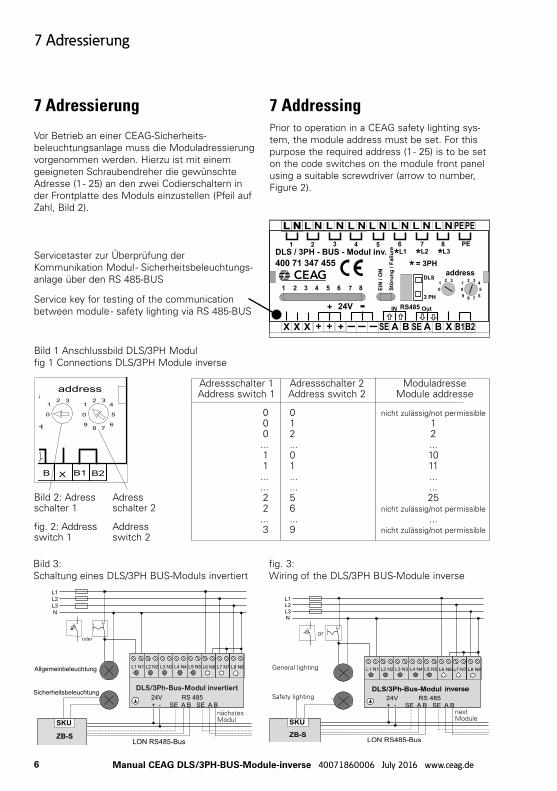
Servicetaster zur Überprüfung der Kommunikation Modul - Sicherheitsbeleuchtungs-anlage über den RS 485-BUS
Service key for testing of the communication between module - safety lighting via RS 485-BUS
Bild 3: Schaltung eines DLS/3PH BUS-Moduls invertiert
fig. 3: Wiring of the DLS/3PH BUS-Module inverse
nächstes Modul
oder
7 Adressierung
Vor Betrieb an einer CEAG-Sicherheits-beleuchtungsanlage muss die Moduladressierung vorgenommen werden. Hierzu ist mit einem geeigneten Schraubendreher die gewünschte Adresse (1 - 25) an den zwei Codierschaltern in der Frontplatte des Moduls einzustellen (Pfeil auf Zahl, Bild 2).
7 AddressingPrior to operation in a CEAG safety lighting sys-tem, the module address must be set. For this purpose the required address (1 - 25) is to be set on the code switches on the module front panel using a suitable screwdriver (arrow to number, Figure 2).
Bild 1 Anschlussbild DLS/3PH Modul fig 1 Connections DLS/3PH Module inverse
Adressschalter 1 Adressschalter 2 Moduladresse Address switch 1 Address switch 2 Module addresse
0 0 nicht zulässig/not permissible 0 1 1 0 2 2 ... ... ... 1 0 10 1 1 11 ... ... ... ... ... ... 2 5 25 2 6 nicht zulässig/not permissible ... ... ... 3 9 nicht zulässig/not permissible
Bild 2: Adress schalter 1
fig. 2: Address switch 1
Adress schalter 2
Address switch 2
1 2 3 4 5
1 2 3 4 5 6 7 8
DLS
3 PH
DLS / 3PH - BUS - Modul
400 71 346 955
EIN
/ O
N
St”
rung / F
ailu
re
IN Out
PE
0
12 3
4
5
678
9
0
12 3
address
24V+ - RS485
* = 3PH** *
6 7 8L1 L2 L3
N PEN PELNL L N L N L N L N L N L
+++ - - - A AB B B1 B2SE SEXX X X
next Module
General lighting
Safety lighting
or
7Manual CEAG DLS/3PH-BUS-Module-inverse 40071860006 July 2016 www.ceag.de
8 Wartung / Instandhaltung
8 Wartung / Instandhaltung
Halten Sie die für Instandhaltung, Wartung und Prüfung von elektrischen Betriebsmitteln geltenden Bestimmungen ein! Im Fall von Rücksendungen benötigen Sie von uns eine RMA - Nummer. Entnehmen Sie bitte weitere Infos hierzu unserer Internetseite www.ceag.de!
9 Entsorgung / RecyclingBeachten Sie bei der Entsorgung defekter Geräte die gültigen Vorschriften für Recycling und Entsorgung. Kunststoffteile sind mit entspre-chenden Symbolen gekennzeichnet. Der in der Leuchte eingebaute LiIon-Akku ist - entsprechend der EU-Richtlinie 2006/66/EG - beim Wechsel an den Vertreiber oder an einen zugelassenen Entsorger zurück zu geben und darf nicht selbst entsorgt werden!
8 Servicing / Maintenance
Observe the relevant national regulations applying to the maintenance, servicing and check-ing of electrical appa-ratus ! In case of returns you need a RMA - number from us. For further information see www.ceag.de!
9 Disposal / RecyclingWhen disposing of defective devices, comply with valid regulations for recycling and waste dis-posal. Plastic parts are marked with correspond-ing symbols.
The LiIon battery integrated in the luminaire must be returned to the seller or an approved disposal location and must not be disposed of by the customer, in accordance with the 2006/66/EG EU directive.
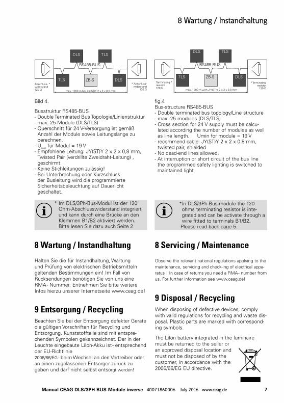
Bild 4.
Busstruktur RS485-BUS - Double Terminated Bus Topologie/Linienstruktur - max. 25 Module (DLS/TLS)- Querschnitt für 24 V-Versorgung ist gemäß
Anzahl der Module sowie Leitungslänge zu berechnen.
- Umin für Modul = 19 V- Empfohlene Leitung: JY(ST)Y 2 x 2 x 0,8 mm,
Twisted Pair (verdrillte Zweidraht-Leitung) , geschirmt
- Keine Stichleitungen zulässig!- Bei Unterbrechung oder Kurzschluss
der Busleitung wird die programmierte Sicherheitsbeleuchtung auf Dauerlicht geschaltet.
* Im DLS/3Ph-Bus-Modul ist der 120 Ohm-Abschlusswiderstand integriert und kann durch eine Brücke an den Klemmen B1/B2 aktiviert werden. Bitte lesen Sie dazu auch Seite 2.
fig.4Bus-structure RS485-BUS - Double terminated bus topology/Line structure- max. 25 modules (DLS/TLS)- Cross section for 24 V supply must be calcu-
lated according the number of modules as well as line length. Umin for module = 19 V
- recommend cable: JY(ST)Y 2 x 2 x 0.8 mm, twisted pair, shielded
- No dead-end lines allowed.- At interruption or short circuit of the bus line
the programmed safety lighting is switched to maintained light
* In DLS/3Ph-Bus-module the 120 ohms terminating resistor is inte-grated and can be activate through a wire fitted to terminals B1/B2.
Please read back page 5.
Abschluss- *widerstand120 Ω
DLS
TLS
TLS
DLSZB-S
RS485-BUS
max. 1200 m bei J-Y(ST)Y 2 x 2 x 0,8 mm
* Abschluss- widerstand
120 Ω
Terminating *resistor120 Ω
DLS
TLS
TLS
DLS*Terminating
resistor120 Ω
ZB-S
RS485-BUS
max. 1200 m with J-Y(ST)Y 2 x 2 x 0.8 mm
Eatons Ziel ist es, zuverlässige, effiziente und sichere Stromversorgung dann zu bieten, wenn sie am meisten benötigt wird. Die Experten von Eaton verfügen über ein umfassendes Fachwissen im Bereich Energiemanagement in verschiedensten Branchen und sorgen so für kundens-pezifische, integrierte Lösungen, um anspruchsvollste Anforderungen der Kunden zu erfüllen.
Wir sind darauf fokussiert, stets die richtige Lösung für jede Anwendung zu finden. Dabei erwarten Entscheidungsträger mehr als lediglich innovative Produkte. Unternehmen wen-den sich an Eaton, weil individuelle Unterstützung und der Erfolg unserer Kunden stets an erster Stelle stehen. Für mehr Informationen besuchen Sie www.eaton.de.
Ihre Ansprechpartner finden Sie unter www.ceag.de.
At Eaton, we’re energized by the challenge of powering a world that demands more. With over 100 years experience in electrical power management, we have the expertise to see beyond today. From groundbreaking products to turnkey design and engineering services, critical industries around the globe count on Eaton.
We power businesses with reliable, efficient and safe electrical power management solutions. Combined with our personal service, support and bold thinking, we are answering tomorrow’s needs today. Follow the charge with Eaton. Visit eaton.eu.
You will find your contact partner at www.ceag.de.
EatonEMEA HeadquartersRoute de la Longeraie 71110 Morges, SwitzerlandEaton.eu
CEAG Notlichtsysteme GmbHSenator-Schwartz-Ring 2659494 Soest, GermanyTel.: +49 (0) 2921 69-870Fax: +49 (0) 2921 69-617E-mail: [email protected] Web: www.ceag.de
© 2016 EatonAlle Rechte vorbehaltenPrinted in GermanyPublikations-Nr. IL451013MLBestell-Nr. 40071860006July 2016