Embed Size (px)
Citation preview
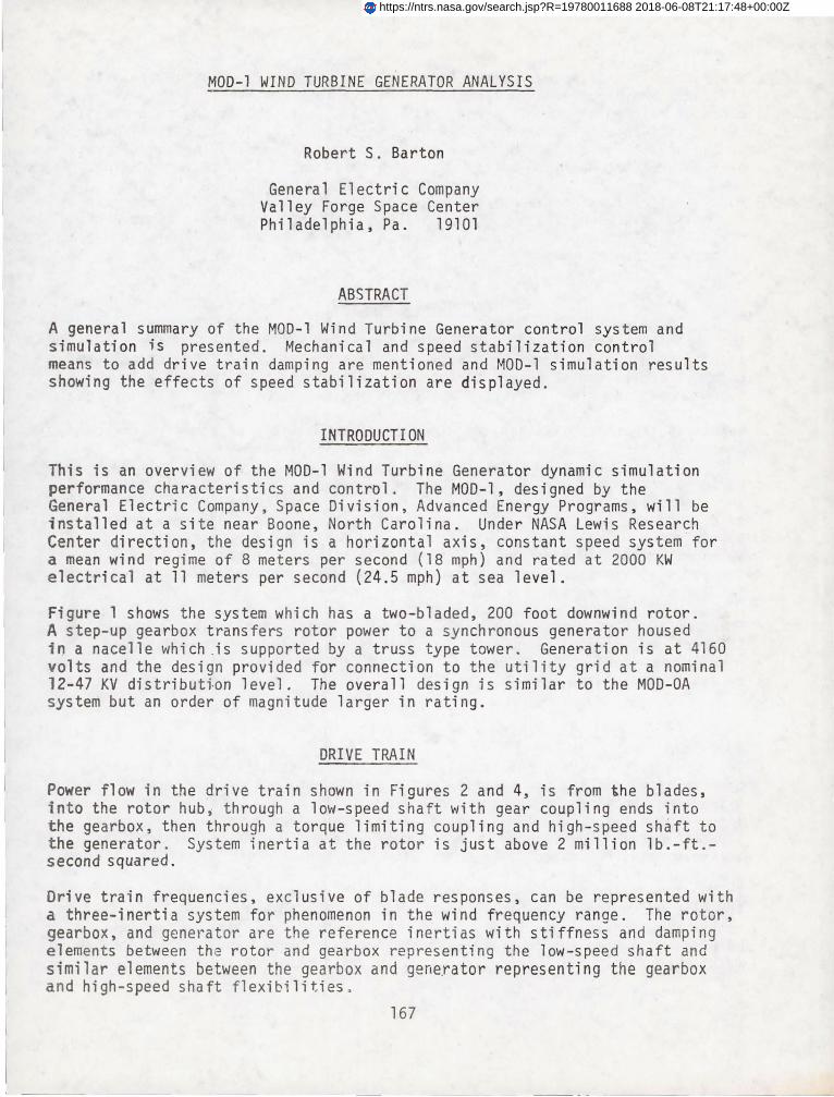
MOO-l WIND TURBINE GENERATOR ANALYSIS
Robert S. Barton
General Electric Company Valley Forge Space Center Philadelphia, Pa. 19101
ABSTRACT
A general summary of the MOD-l Wind Turbine Generator control system and simulation is presented. Mechanical and speed stabilizati on control means to add drive train damping are mentioned and MOO-l simulation results showing the effects of speed stabilization are displayed.
INTRODUCTI ON
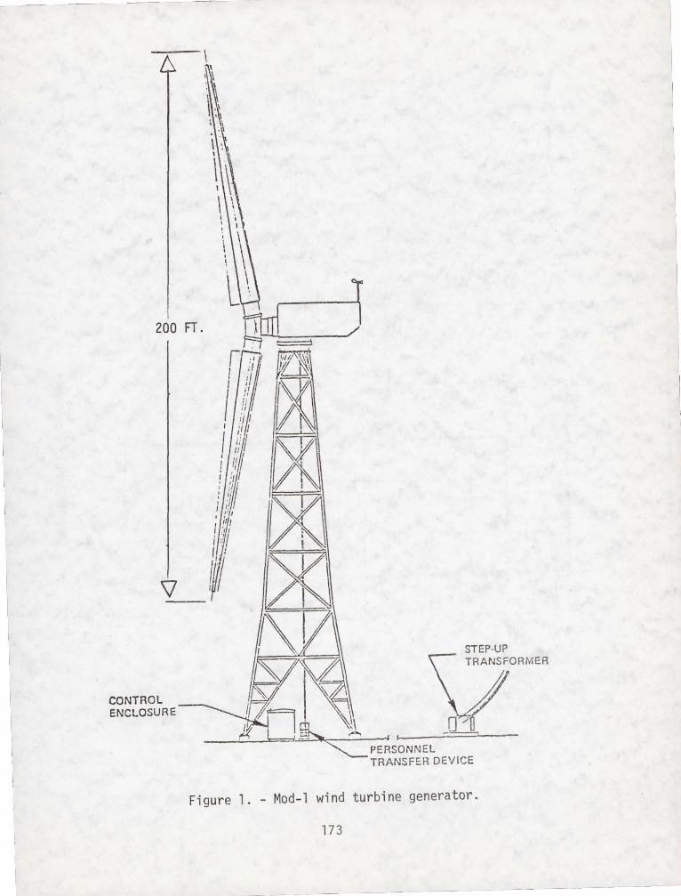
This is an overview of the MOD-l Wind Turbine Generator dynamic simulation performance characteristics and control. The MOO-l, designed by the General Electric Company, Space Division, Advanced Energy Programs, will be installed at a site near Boone, North Carolina. Under NASA Lewis Research Center direction, the design is a horizontal axis, constant speed system for a mean wind regime of 8 meters per second (18 mph) and rated at 2000 KW electrical at 11 meters per second (24.5 mph) at sea level.
Figure 1 shows the system which has a two-bladed, 200 foot downwind rotor. A step-up gearbox transfers rotor power to a synchronous generator housed i~ a nacelle which .is supported by a truss type tower. Generation is at 4160 volts and the design provided for connection to the utility grid at a nominal 12-47 KV distributton level. The overall design is similar to the MOD-OA system but an order of magnitude larger in rating.
DRIVE TRAIN
Power flow in the drive train shown in Figures 2 and 4, is from the blades, into the rotor hub. through a low-speed shaft with gear coupling ends into the gearbox, then through a torque limiting coupling and high-speed shaft to the generator . System inertia at the rotor is just above 2 million lb.-ft.second squared.
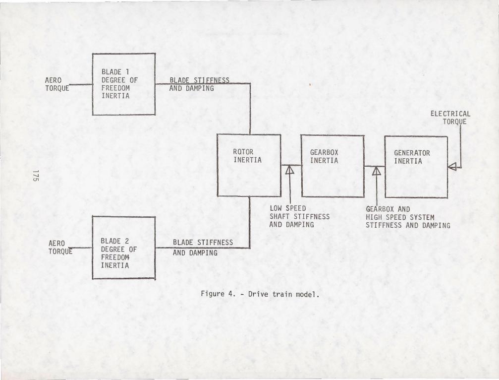
Drive train frequencies, exclusive of blade responses, can be represented with a three-inertia system for phenomenon in the wind frequency range. The rotor, gearbox, and generator are the reference inertias with stiffness and damping elements between the rotor and gearbox representing the low-speed shaft and similar elements between the gearbox and generator representing the gearbox a nd high-speed shaft flexibilities .
167
https://ntrs.nasa.gov/search.jsp?R=19780011688 2018-06-08T21:17:48+00:00Z
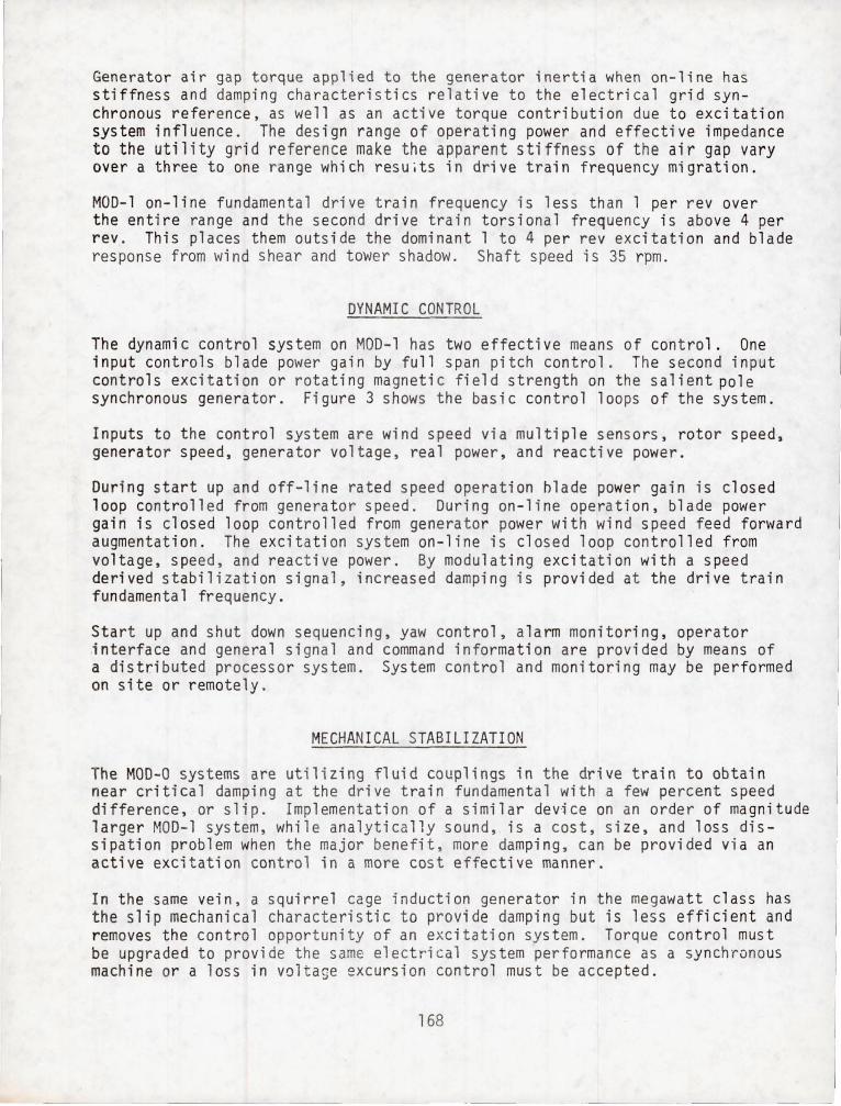
Generator air gap torque appl i ed to the generator inertia when on-line has s ti f fness and damping characteristics relative to the electrical grid synch ronous r eference, as well as an active torque contribution due t o excitati on system influence. The design range of operating power and effective i mpedance to the utility grid reference make the apparent stiffness of the air gap vary over a three to one range which resuits in drive train frequency mig ration.
MOD-l on-line fundamenta l drive train frequency is less than 1 per rev over the entire range and the second drive train torsional frequency is abo ve 4 per rev. This places them outside the dominant 1 to 4 per rev excitation and bl ade response from wind shear and tower shadow. Shaft speed is 35 rpm.
DYNAMIC CONTROL
The dynamic control system on MOD-l has two effective means of control. One i nput controls blade power gain by full span pitch control. The second input contro l s excitation or rotating magnetic field strength on the salient pol e synchronous generator. Figure 3 shows the basic control loops of the sys t em.
Inputs to the control system are wind speed via multiple sensors, rotor speed , gener ator speed, generator voltage, real power, and reactive power.
Durin g start up and off-line rated speed operation hlade power gain is clos ed loop controlled from generator speed. During on-line operation, blade power ga in is cl osed loop controlled from generator power with wind speed fe ed forw ard augmentation. The excitation system on-line is closed loop controlled from voltage, speed, and reactive power. By modulating excitation with a s peed de rived stabilization signal, increased damping is provided at the drive train fu ndamental frequency.
Start up and shut down sequencing, yaw control, alarm monitoring, operator interface and general signal and command information are provided by means of a distributed processor system. System control and monitoring may be performe d on site or remotely.
MECHANICAL STABILIZATION
The MOD-O systems are utilizing fluid couplings in the drive train to obtai n near critical damping at the drive train fundamental with a few percent speed difference, or slip. Implementation of a similar device on an order of ma gn itude larger MOD-l system, while analytically sound, is a cost, size, and loss dis sipation problem when the major benefit, more damping, can be provided via an active excitation control in a more cost effective manner.
In the same vein, a squirrel cage induction generator in the megawatt clas s has the slip mechanical characteristic to provide damping but is less efficient an d removes the control opportunity of an excitation system. Torque control must be upgraded to provide the same electr';c al system perfo rmance as a synchronous machine or a loss in voltage excursion control must be accepted.
168
-- l SPEED STABILIZATION
Inputs to synchronous generator excitation systems to improve power transfer stability margins have been used on large power systems for some time. Reference 1 is one of the early papers on the technique. Signals derived from shaft speed and output power have been used to modulate the excitation system to improve the apparent damping of the generator mechanical system.
limitations exist in the frequency response of an excitation system that determine whether stabilization techniques will be effective at the desired frequency. For example, an attempt, reported in Reference 2, was made to decrease the 2 per rev response on MOD-O with less than encouraging results. A careful analysis of each system a~d suitable compensation of th~ control signal must be provided for optimum effect.
On the MOD-l system, a shaft speed signal, suitably compensated, is utilized to vary excitation and improve the effective damping of the fundamental on-line drive train torsional frequency. This frequency is relatively stable over the power range of operation because the mechanical stiffness elements are relatively "soft" and the variable generator stiffness thus has less influence on the fundamental.
The unstabi1ized fundamental is around 2.4 radians per second with an unstabi1ized damping of around 5 percent of critical. vary slightly with the voltage regulator gain settings, power electrical system effective impedance and voltage. The speed system improves the MOD-l damping to a respectable 25 percent followi ng.
SIMULATION MODEL
or 0.7 per rev These numbers
level, and stabilization in the results
Since the MOD-l system is not yet built, the characteristics presented are based on analytical frequency and time domain studies using the general model shown in Figure 3. In addition to the drive train previously noted, blade and electrical dynamics are carried as well as detail modelling of the torque and excitatior. control systems. Figure 4 shows the basic drive train mechanical model.
Simulation for time domain results on the MOD-1 system is implemented on a hybrid computer system. The mix of small time constants in the controls and low frequency mechanical ··responses plus the d~sire to examine long time response to filtered random noise "wind" make this analytical tool superior to the conventional di~ital numerical integration approach. Digital techniques are utilized for frequency domain analysis. Hybrid output is on 24 channels of pen recorder with 16 channels on fixed variables. Table 1 shows the fixed output variables used.
169
STABILIZER SIMULATION RESULTS
In the limited scope of this presentation, only the dampin g augmentation performance provided by the MOD-r speed stabilizer will be shown.
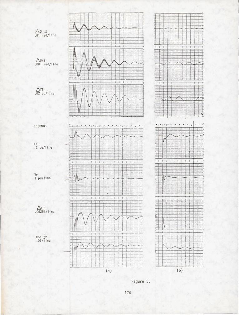
First, the system response to a step initial deflection condition will be shown with the excitation system closed loop but without wind input or torque control. Figure 5a shows the case without the s~abi lizer. Time scale is one second per division ana ampl ituae scales are indicated. The nigh frequency osci 11ation superimposed on the fundamental is a gearbox inertia mode. The fundamental is 2.4 radians per second at 5% damping ratio.
Figure 5b illustrates the excitation system response to a 1.5% step change in on-line voltage reference. The MOD-l solid state voltage regulator is capable of negative field forcing and is set for about 15% damping ratio oscillatory behavior.
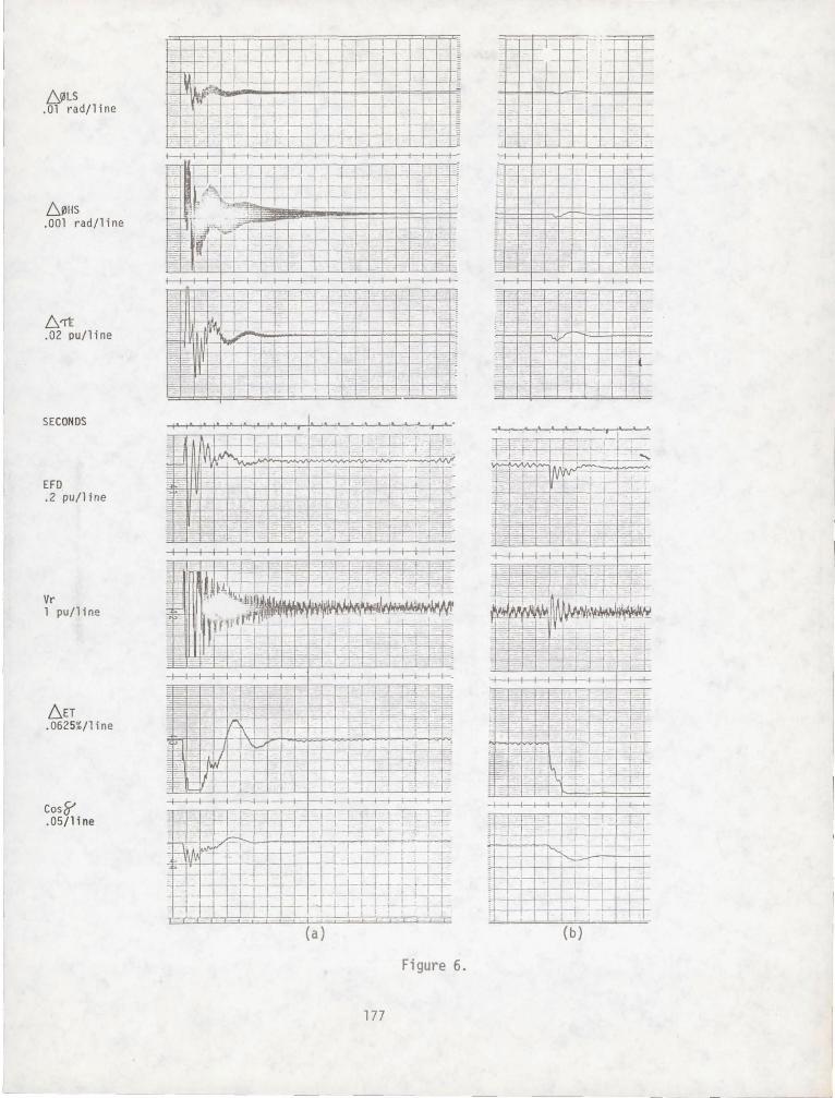
In Figure 6a, the same initial condition as in 5a is applied but with the stabilizer circuit closed loop. The damping has increased to a respectable 25 percent of critical at the fundamental. No improvement is observed or expected at higher frequencies of oscillation as the stabilizer loop is keyed to a single frequency. Figure 6b illustrates the response to a step change in on-line voltage reference with the stabilizer. Note that there is a penalty to pay for the stabilizer, a slight increase in excitation system oscillation which will contribute to increased voltage variation.
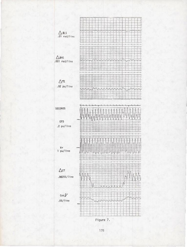
Figure 7 shows the effect of steady wind forcing the system, with response to tower shadow and wind shear continuous excitation clearly showing up in mechanical and electrical system response. System response to two steps, down and up; in voltage reference are shown. The steady state peak to peak terminal voltage excursion is less than 1.0 percent, will be reducec with suitable compensation and will be less at a critical load bus. This magnitude is within acceptable utility standards at the frequency of occurance.
CONCLUSIONS
The technique of stabilization by utilizing the excitation system capabilities of synchronous generators is shown to be an effective means of increasing the damping of the fundamental torsional frequency of megawatt class horizontal axis wind turbines and is being applied for that purpose on the MOO-1 system.
REFERENCES
1. Demello, F. P. and Concorqia, C., Concepts of Synchronous Machine Stability as Affected by Excitation Control, IEEE Transactions, Vol . PAS-88 No.4, pp 316-328, 1969.
2. Gebben, V. D., Investigation of Excitation Control For Wind Turbine Stability, EROA/NASA/1028-77/3, NASA TM-73745, August, 1977.
170
--~ -- --
DISCUSSION
Q. Were systems with and without wind feed forward tried? MOD-O test data shows both good and bad results .
A. MOD-l simulation has used wind feed forward in an idealized manner with good results. The idealization incorporates sensor and mechanism time constants but assumes that the wind sensed for control purposes is the same as the wind producing rotor torque with suitable time shift to accommodate upwind sensor mounting .
MOD-l has hardware to sense the wind field with more than one sensor where MOD-O uses a single sensor. If the sensed wind for control is not representative of the wind field producing rotor torque, ambivalent results can be expected. Further work is indicated in the implementation of an inexpensive means of large area wind sensing for wind turbine control.
Q. What was the technical tradeoff concerning selection of a synchronous generator with active excitation control versus an induction generator?
A. Basically, an induction generator was rejected for MOD-l because of excessive voltage dips due to wind gusts when connected by reasonable distribution system connection impedances. Performance simulation runs had twice the voltage dip with induction than with synchronous for the same effective pitch control gain and wind disturbance. Also, the MOD-l specification called for a synchronous machine .
The MOD-l synchronous with speed stabilizer provjdes comparable on-line drivetrain torsional frequency damping with that resulting from an induction generator without the loss in efficiency. This type of machine decision tends to be site oriented and such factors as very small connection impedance, faster response blade power gain control, and smaller machine rating may contribute to a different conclusion for a different application.
Q. Is the blade pitch control l oop inactive in damping the system as you have modeled it?
No, closed loop pitch control increases system stability and improves drivetrain damping. The res ults showi ng speed stabilizer and excitation system performance to step i nput s were run with open loop pitch control and no wind disturbance in order to bette r i llustrate the main topic.
171
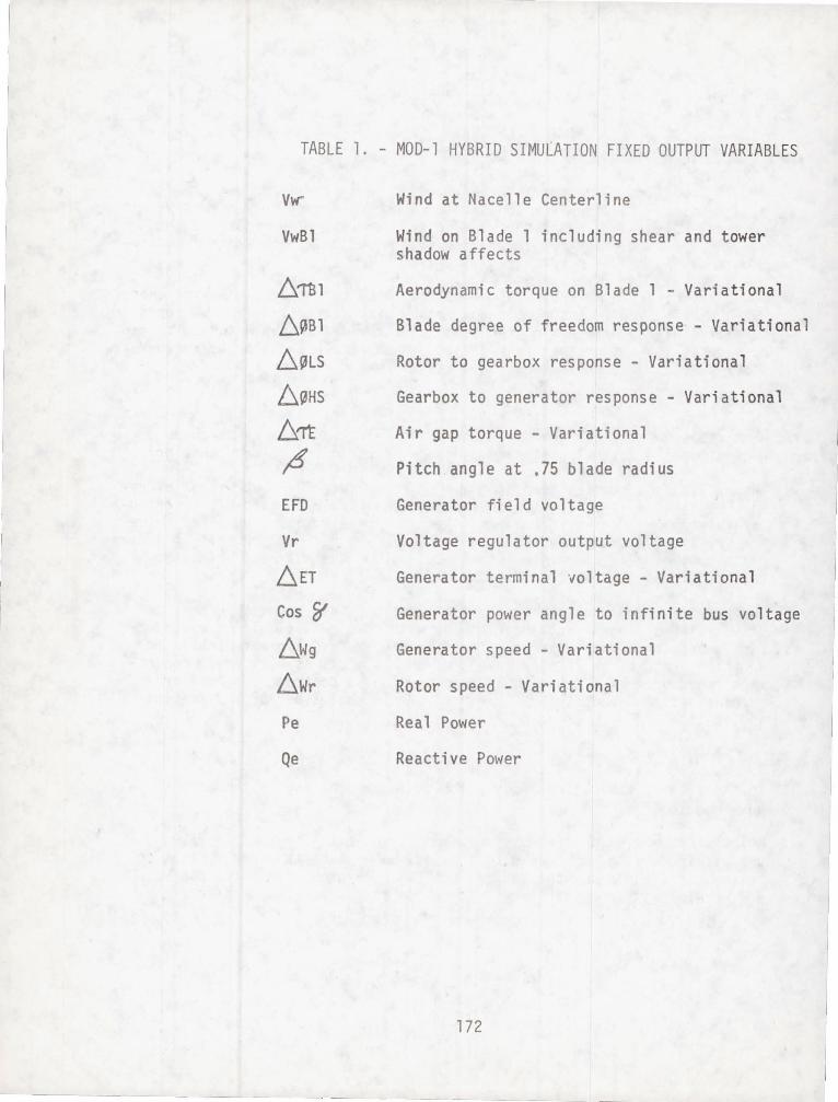
TABLE 1. - MOD-1 HYBRID SIMULATION FIXED OUTPUT VARIABLES
VwBl
61131
L~Bl
~~LS
~~HS
!:::.'Tt 4 EFD
Vr
.6ET
Cos ~
.6Wg
6Wr
Pe
Qe
Wind at Nacelle Centerline
Wind on Blade 1 including shear an d tower shadow affects
Aerodynamic torque on Blade 1 - Variational
Blade degree of freedom response - Variational
Rotor to gearbox response - Varia tional
Gearbox to generator response - Variational
Air gap torque - Variational
Pitch angle at .75 blade radius
Generator field voltage
Voltage regulator output voltage
Generator terminal voltage - Varia t i onal
Generator power angle to infinite bus vo ltage
Generator speed - Variational
Rotor speed - Variational
Real Power
Reactive Power
172
I I 1
I
I
- - _ _____ J
I I
I j
I 1
I
I j
I
I ,
l l_
200 FT.
CONTROL ENCLOSURE
-- -- - --- - - - -
STEP-UP \lORMER D,I
_~--'====L.-==--::lI~~~ II---'---:==--
PERSONNEL TRANSFER DEVICE
Figure 1. - Mod-1 wind turbine generator.
173
-_. ----~ -- - ---

HUB ---
WIND LOOP
WIND AND ROTOR
PITCH
~ AEROD YNAMICS
WIND DISTURBANCE
HIGH SPEED SHAFT
STEP UP GEARBDX
Figure 2. - Drive train power flow.
TORQUE CONTROL SYSTEM ..... POWER LOOP
'\. S~ ~~D ",OP
ME CHAN I CAL ... TORQUElI"""
BLADE AND DRIVE TRAIN MECHANICAL DYNAMI CS
~ ELECTRICAL ... ... TORQUE ..
'\. STABILIZER ~LOOP
EXCITATI ON CONTROL SYSTEM
FIELD
GEN ERATOR 7
GENERATOR AND GRI D ELECTRICAL DYNAMICS
VOLTAGE LOOP
Figure 3. - Simulation block diagram.
174
-
'-I Ul
AERO TORQUE
AERO TORQU IE
BLADE 1 DEGREE OF FREEDOM INERTIA
BLADE 2 DEGREE OF FREEDOM INERTIA
BLADE SIlFFNES~ AND DAMPING •
ROTOR GEARBOX INERTIA INERTIA
L :1
LOW SPEED SHAFT STI FFNESS AND DAMPI NG
BLADE STI FFNESS AND DAMPING
Figure 4. - Drive train model.
ELECl TC . .
GENERATOR INERTIA
~ L ~
GEARBOX AND HIGH SPEED SYSTEM STIFFNESS AND DAMPING
AL E
6~ LS . 01 rad/~ i ne
.6J,HS .001 rad/line
l:s.rt l' .02 pu/ lne
SECONDS
EFD .2 pu/line
'fr 1 pu/l.ine
D.ET .0625%'/1 i ne
Cos s..DS/line
, J .I
•• ••• , e •• " , I'
t · -
I - I I I I I I I I I I - I II .__+ -- -I
I I 1 I 1 I I I I I I I ! 1 -I
1 -I. - - I--+--+--r-r, , UL~~~-rtl!JI.1 1
' J!.~ / . ,...1, ~n : ~J,..-0.
r[i~iV ~l~~ffl~-rt] fH! L j . I-i-t--r ', 1 -L
t' "1 I 1 I 1 1 1 I 1 -f-'-1- I I I 1 I 1 I 1 I' I !' I +--1 ~ Ii I ~ ~- I.I i._f-r-j-t-- i ·I~ t ~1 - , . .] . . ~ ~ _--I. , ;~
~IL'-C~-+ - : "J-r-1Ii'7f! -, ~-;-~L. t~t [ __ l I ." ~ ;·-,·- 1--. I I I '=8=-; '-iI-rj"-=1-_~.=L; , i ·-t- ,- 1-- - ~
- t - l I ! l-!~ -4- 1 -' - ... 1 ,. ',_ , 1--1.....- 1 1--' - - I . "1 '. __ I . . I: I ~_.J_ . __
_ . (a)
Figure 5.
176
iFlFt . I -+ '" .Jc......l--l-l+-l-t-J.IT_L _-H--+I
; 1=1 i ~+ . !"11- I ~
. 1 I !! l
",I
=.
I I ..1
;; r=-
1 !
1-1
+ :lJ.:
1 l..l~-l-I '!
_L I I _ L I I
- I ' I ,
"" ! J I I ~ ..l J. I - ! -4-
- 1 ' ..1 I
-r J +
1- --I '-lIII :
I ~ -:1 10-1 I ~ I ·
• v
=1. - 1 =-1-'
,=
I , I , : .
I : ' -I i_ I , _
.1 ,-: ....::i. -. r !-h
1 j -;:'" :.- i:-· i ' ~
;3~ I >= 7. ; : .
I
i : ;
! 1 ~ ..i : j
I ! :
- I, ~ i-
~r-I\-r-f;""p,-j \
J...l -t-+ I J 4-;
:--1 I I I I I I I , ~
I
I
f~
ty)lS .01 radll i ne
6~flS .001 radll i ne
6'Tt .02 pull i ne
SECONDS
EFD .2 pu/li ne
Vr 1 pull i ne
6.ET .0625%/line
Cos&-, .05/11 ne
" I I I I I I I I I I I I I I I I I
1-=1 I I J -::=- 1-' L 'l H'., I f-'-- J--:-lf¥, 1-1. 1 I--
" f= I i - ,
,-I~
I -
-:
" I, .. ",,' ", ,. ,,13" l'rA I' I' I' ' _; ' '-±i--'I=r l T LL. 11~'-2' l"",,-U , ,---1-..1 __ ~ :: I~~r ' 1~- fIT:C ~~ iii _ :- - i' .:-.
I I ,"1
; !
I 1 I I I I 1 1 I J3
I ' ! i
I I I I I 1 'j~ m=FJH...LLJ--i .1-- I ; t- . ' .•. . I -, I~L_Ll I -I .-l---i-+-, I---,-r - I.,.' ·...:..l '1 I' I :', i.
~1-1~H=IJ1-j Lr}l_ff !t}L :1Tl r-r- __ -- L f '-+~rT --I j JiJ-l-l- i I ~ . t, ~ .~~
'.1'- • • , (a)
Figure 6.
177
'---'-if' -. r :-~--l--I-+---t I 1 -1_1_ --'- - - '- - -i I, '-.!_'-
_ II-' _L...j--l_-+--
I-I - i-1--II- 1-1- 'l-
I I I I I I
-l-l- + -I-+-t-J - t- --/-'
~t ~r- I~ ,I-I--
-
I I
i !
••• I • • ' ......
T ,I
6~LS .01 rad/1ine
6~HS .001 rad/1 ine
.02 pu/l i ne
SECONDS
EFD
.2 pu/ l ine
Vr 1 pu/line
.0625%/li ne
cosl/ .05/1 i ne
I~ I-+=-l--J.--l-+-+-i-f-- - -'-f-- -'-l-cj-l-~-+-+-!---;l ~ 1 ~ 1'-i+.-l-i:-++-+-+-'-i-+-lH--f-+-+- - ++-!--+;q
! ! :
1 ,:
W---i-W--+--l-+-+-+-l--l-+-IH--t-+--I-t- b: i
- I
1 I :
1:,-: ~ -- -
-+-+-+-- k-
E" -- 1- ,
I~ ~llii~~ ~I~K~~W~~ - I ;_ __ - r~= ~ __ -::,:. _ - - I
C _~""- ~:. . ,
- _ ~ r, _ - - - - - -- ! l
~ ~ - = - -j-: _. 1:.- _ ~ ._ _ I~ . . ..
+-+-_- I r
1\ ' ! .
178
J