Embed Size (px)
Citation preview
Motion Capture File Formats Explained 1
Motion Capture File Formats Explained M. Meredith S.Maddock
{M.Meredith, S.Maddock}@dcs.shef.ac.uk http://www.dcs.shef.ac.uk/~{mikem, steve}
Department of Computer Science, University of Sheffield 211 Portobello Road,
Sheffield, S1 4DP 1 Introduction Traditional character animation is an involved process that takes large amounts of time using skilled artists to manually pose characters using tools such as 3D Studio Max [Max], Maya [Maya] or Poser [Poser]. However with the ever increasing demands placed on computer graphics for better looking 3D scenes and in shorter spaces of time, alternative character animation techniques are needed. While the use of forward and backward kinematics can be used to speed up the process of traditional character positioning, the overall creation phase is still a comparatively slow one. Therefore, to meet the demands of modern character animation many production houses have turned to motion capture technologies, in a bid to find a better solution. With the aid of motion capture techniques much of the laborious posture configuration is eliminated as character animation is recorded directly from actors performing the desired motion, thereby reducing the need of artists to manually position characters. Motion capture devices allow the recording of live motions by tracking a number of key points in space over time, which are translated into a 3 dimensional digital representation. The captured subject can be anything that exists in the real world, with the key points positioned on the object such that they best represent the orientations of the moving parts of the object, for example the joints or pivot points. In order to accurately triangulate marker positions at least 4 cameras are used, however generally no more than 32 are used. The use of motion capture data to animate computer characters has been used in television commercials to promote such products as Coke Cola and Barbie1, movie productions, such as Final Fantasy: The Spirits Within2 and computer games. Examples of the use of motion capture data in computer games can be seen in Actua Soccer 23, Fifa 20014 and the Tomb Raider series5. The success of motion capture has led to a number of production houses that can record and provide motion data6, however many companies have developed their own file format. This means that file formats of motion capture data are far from standard, however the ASCII nature of many of the formats make it reasonably easy to decode and understand by simple inspection of the data. This document starts by providing a brief overview of the terminology and style of notation that will be used to describe the file formats, followed by a list of many of the motion capture formats in use today. Two of the more common formats are then explained in terms of their structure and the procedure required for correct interpretation of the data for playback. This is followed by fragments of C++ code, which makes use of the OpenGL library routines, to illustrate a possible program structure for a motion capture decoder and player. As an indication of the increasing foothold that motion capture technology has in computer animation, there are currently a number of books dedicated to the understanding and processing of motion capture data. Appendix A contains a bibliography of some of these books and other motion capture research papers along with comments on some of the texts.
1 House of Moves Motion Capture Studio, http://www.moves.com 2 Final Fantasy: The Spirits Within, http://www.finalfantasy.com 3 Actua Soccer 2, Gremlin Interactive, http://actuaweb.gamestats.com/as2 4 Fifa 2001, Electronic Arts, http://fifa2001.ea.com 5 Tomb Raider, Core Design Incorporated, http://www.tombraider.com 6 Production houses that supply motion capture data include BioVision, http://www.biovision.com, Motion Analysis, http://www.motionanalysis.com and House of Moves, http://www.moves.com
Motion Capture File Formats Explained 2
2 Background Information This section provides a short review of the terminology and notational style that will be used to describe the processes involved in reading and processing motion capture data. 2.1 Terminology The following list outlines some of the more important keywords that will be used to identify and describe different aspects of a motion: • Skeleton – The whole character for which the motion represents. • Bone – The basic entity in representing a skeleton. Each bone represents the smallest segment
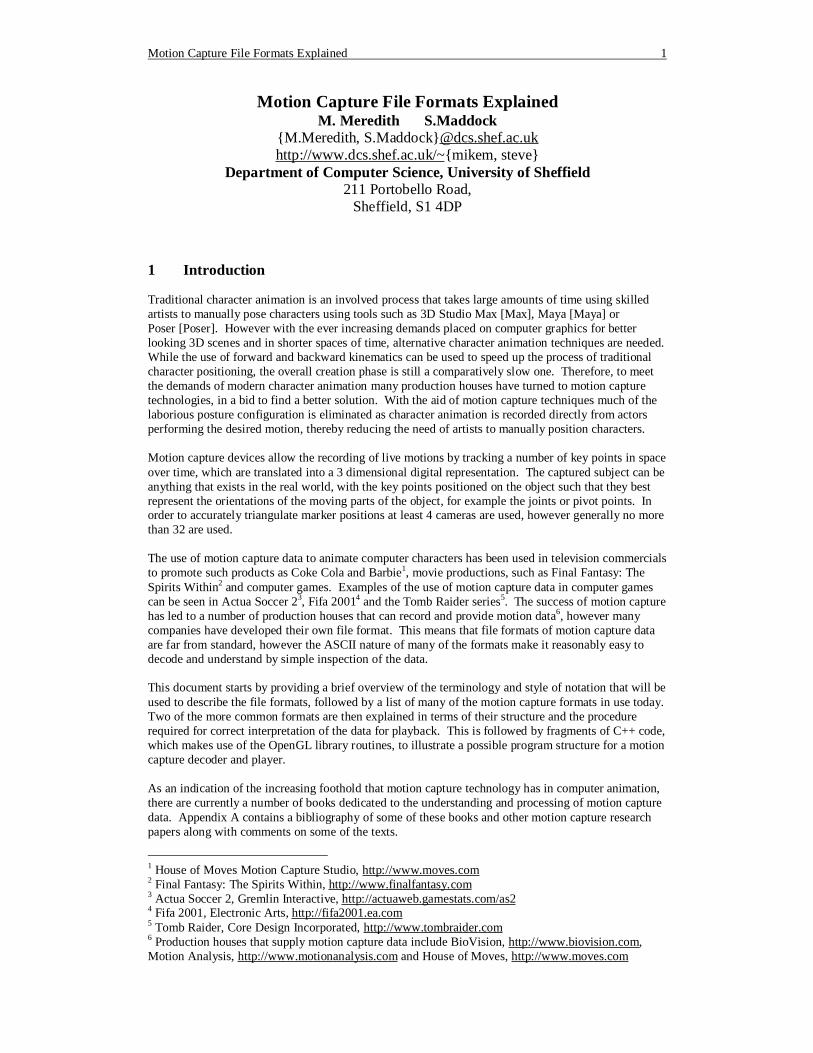
within the motion that is subject to individual translation and orientation changes during the animation. A skeleton is comprised of a number of bones (usually in a hierarchical structure, as illustrated in figure 2.1), where each bone can be associated with a vertex mesh to represent a specific part of the character, for example the femur or humerus.
• Channel or Degree of Freedom (DOF) – Each bone within a skeleton can be subject to position, orientation and scale changes over the course of the animation, where each parameter is referred to as a channel (or DOF). The changes in the channel data over time give rise to the animation.
• Frame – Every animation is comprised of a number of frames where for each frame the channel data for each bone is defined. Motion capture data can be captured as high as 240 frames per second, however in many applications a rate of 30 or 60 frames per second tends to be the norm. High frame rates are used to capture motions that contain high frequency content such as a combination of karate actions. Although in many cases the extra detail cannot be displayed during a real-time playback because of maximum refresh rates of display hardware7, it can provide useful information for adding motion blurring to the animation or simply for motion analysis.
2.2 Notation During the discussion on transforming bones to correctly position and orientate them for an animation, matrix arithmetic will be used to demonstrate the motion decoding and displaying algorithms. The nomenclature used when writing matrix expressions is right to left, as illustrated in Equation 2.1 where v’ and v are the transformed and original vertices respectfully and M is the transform matrix. (This convention is used over the traditional left to right approach, v’ = vM, because it relates more directly to the OpenGL graphics pipeline, where vertices are pushed in after the transforms)
7Affordable, everyday monitor refresh rates presently max out at about 100hz, and a sustained 60fps rate in a modern computer game is considered an excellent mark to reach.
Root
Head
Left Hand
Right Foot Left Foot
Right Hand
Figure 2.1: Hierarchical Structure for a Human Figure
Motion Capture File Formats Explained 3
v' = Mv (2.1) This convention is particularly important when constructing a rotation matrix from its 3 separate Euler angles since matrix multiplication is not commutative. The composite right to left rotation matrix, R, based on the separate rotation matrices about each axis, Rx, Ry, and Rz, is illustrated in Equation 2.2, where the composition order is “XYZ”. Since matrix multiplication is associative, brackets will be omitted from such equations. Rv = RxRyRzv (2.2) The motion of an individual bone consists of translation, rotation and scale components (depending on the channels defined for the bone), which can be merged together to give an overall transform using homogeneous coordinates. Unless otherwise stated, the combination order of these different transforms to give the full transform will always follow the form illustrated in Equation 2.3, where S, R and T are the separate scale, rotation and translation matrices respectfully.
M=TRS (2.3) In most motion capture file formats, the data is presented in a hierarchical manner and the formula derived in Equation 2.3 only gives the local transformation of a bone. The local transformation of a bone describes its orientation within in its local coordinate system, which in turn is subject to its parent’s local orientations. To obtain a global matrix transform for a given bone, the local transform needs to be pre-multiplied by its parent’s global transform, which itself is derived my multiplying its local transform with its parent’s global transform and so on. Equation 2.4 outlines this combination sequence, where n is the current bone whose parent bone is n - 1 and n = 0 is the bone at the root of the hierarchy.
∏=
=n
i
ilocal
nglobal MM
0
(2.4)
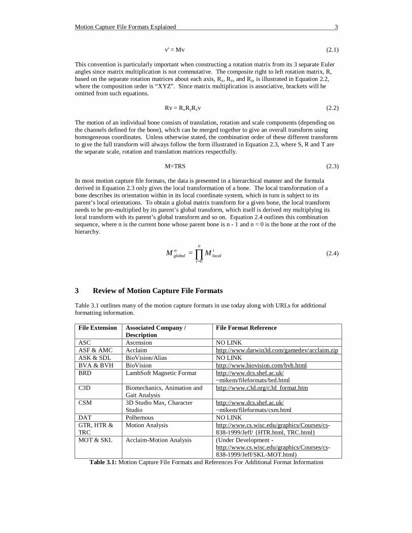
3 Review of Motion Capture File Formats Table 3.1 outlines many of the motion capture formats in use today along with URLs for additional formatting information.
File Extension Associated Company / Description
File Format Reference
ASC Ascension NO LINK ASF & AMC Acclaim http://www.darwin3d.com/gamedev/acclaim.zip ASK & SDL BioVision/Alias NO LINK BVA & BVH BioVision http://www.biovision.com/bvh.html BRD LambSoft Magnetic Format http://www.dcs.shef.ac.uk/
~mikem/fileformats/brd.html C3D Biomechanics, Animation and
Gait Analysis http://www.c3d.org/c3d_format.htm
CSM 3D Studio Max, Character Studio
http://www.dcs.shef.ac.uk/ ~mikem/fileformats/csm.html
DAT Polhemous NO LINK GTR, HTR & TRC
Motion Analysis http://www.cs.wisc.edu/graphics/Courses/cs-838-1999/Jeff/ {HTR.html, TRC.html}
MOT & SKL Acclaim-Motion Analysis (Under Development - http://www.cs.wisc.edu/graphics/Courses/cs-838-1999/Jeff/SKL-MOT.html)
Table 3.1: Motion Capture File Formats and References For Additional Format Information
Motion Capture File Formats Explained 4
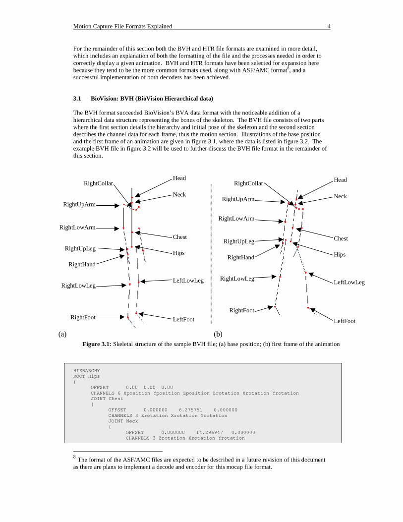
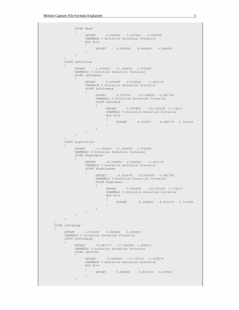
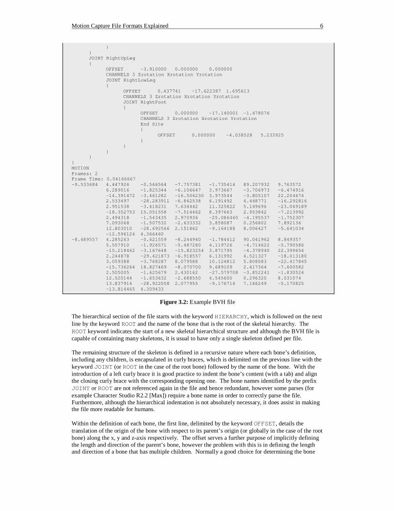
For the remainder of this section both the BVH and HTR file formats are examined in more detail, which includes an explanation of both the formatting of the file and the processes needed in order to correctly display a given animation. BVH and HTR formats have been selected for expansion here because they tend to be the more common formats used, along with ASF/AMC format8, and a successful implementation of both decoders has been achieved. 3.1 BioVision: BVH (BioVision Hierarchical data) The BVH format succeeded BioVision’s BVA data format with the noticeable addition of a hierarchical data structure representing the bones of the skeleton. The BVH file consists of two parts where the first section details the hierarchy and initial pose of the skeleton and the second section describes the channel data for each frame, thus the motion section. Illustrations of the base position and the first frame of an animation are given in figure 3.1, where the data is listed in figure 3.2. The example BVH file in figure 3.2 will be used to further discuss the BVH file format in the remainder of this section.
HIERARCHY ROOT Hips { OFFSET 0.00 0.00 0.00 CHANNELS 6 Xposition Yposition Zposition Zrotation Xrotation Yrotation JOINT Chest { OFFSET 0.000000 6.275751 0.000000 CHANNELS 3 Zrotation Xrotation Yrotation JOINT Neck { OFFSET 0.000000 14.296947 0.000000 CHANNELS 3 Zrotation Xrotation Yrotation
8 The format of the ASF/AMC files are expected to be described in a future revision of this document as there are plans to implement a decode and encoder for this mocap file format.
Head
Neck
Chest
Hips
LeftFoot
LeftLowLeg
RightCollar
RightUpArm
RightUpLeg
RightHand
RightLowLeg
RightFoot
Head
Neck
Chest
Hips
LeftFoot
LeftLowLeg
RightCollar
RightUpArm
RightUpLeg
RightHand
RightLowLeg
RightFoot
(a) (b)
RightLowArm
RightLowArm
Figure 3.1: Skeletal structure of the sample BVH file; (a) base position; (b) first frame of the animation
Motion Capture File Formats Explained 5
JOINT Head { OFFSET 0.000000 2.637461 0.000000 CHANNELS 3 Zrotation Xrotation Yrotation End Site { OFFSET 0.000000 4.499004 0.000000 } } } JOINT LeftCollar { OFFSET 1.120000 11.362855 1.870000 CHANNELS 3 Zrotation Xrotation Yrotation JOINT LeftUpArm { OFFSET 4.565688 2.019026 -1.821179 CHANNELS 3 Zrotation Xrotation Yrotation JOINT LeftLowArm { OFFSET 0.219729 -10.348825 -0.061708 CHANNELS 3 Zrotation Xrotation Yrotation JOINT LeftHand { OFFSET 0.087892 -10.352228 2.178217 CHANNELS 3 Zrotation Xrotation Yrotation End Site { OFFSET 0.131837 -6.692379 1.711456 } } } } } JOINT RightCollar { OFFSET -1.120000 11.362855 1.870000 CHANNELS 3 Zrotation Xrotation Yrotation JOINT RightUpArm { OFFSET -4.708080 2.034554 -1.821179 CHANNELS 3 Zrotation Xrotation Yrotation JOINT RightLowArm { OFFSET -0.263676 -10.428555 -0.061708 CHANNELS 3 Zrotation Xrotation Yrotation JOINT RightHand { OFFSET 0.000000 -10.255345 2.178217 CHANNELS 3 Zrotation Xrotation Yrotation End Site { OFFSET -0.140882 -6.671274 1.711456 } } } } } } JOINT LeftUpLeg { OFFSET 3.910000 0.000000 0.000000 CHANNELS 3 Zrotation Xrotation Yrotation JOINT LeftLowLeg { OFFSET -0.441177 -17.569450 1.695613 CHANNELS 3 Zrotation Xrotation Yrotation JOINT LeftFoot { OFFSET -0.043946 -17.197315 -1.478076 CHANNELS 3 Zrotation Xrotation Yrotation End Site { OFFSET 0.000000 -3.933155 5.233925 } }
Motion Capture File Formats Explained 6
} } JOINT RightUpLeg { OFFSET -3.910000 0.000000 0.000000 CHANNELS 3 Zrotation Xrotation Yrotation JOINT RightLowLeg { OFFSET 0.437741 -17.622387 1.695613 CHANNELS 3 Zrotation Xrotation Yrotation JOINT RightFoot { OFFSET 0.000000 -17.140001 -1.478076 CHANNELS 3 Zrotation Xrotation Yrotation End Site { OFFSET 0.000000 -4.038528 5.233925 } } } } } MOTION Frames: 2 Frame Time: 0.04166667 -9.533684 4.447926 -0.566564 -7.757381 -1.735414 89.207932 9.763572
6.289016 -1.825344 -6.106647 3.973667 -3.706973 -6.474916 -14.391472 -3.461282 -16.504230 3.973544 -3.805107 22.204674 2.533497 -28.283911 -6.862538 6.191492 4.448771 -16.292816 2.951538 -3.418231 7.634442 11.325822 5.149696 -23.069189 -18.352753 15.051558 -7.514462 8.397663 2.953842 -7.213992 2.494318 -1.543435 2.970936 -25.086460 -4.195537 -1.752307 7.093068 -1.507532 -2.633332 3.858087 0.256802 7.892136 12.803010 -28.692566 2.151862 -9.164188 8.006427 -5.641034 -12.596124 4.366460
-8.489557 4.285263 -0.621559 -8.244940 -1.784412 90.041962 8.849357 5.557910 -1.926571 -5.487280 4.119726 -4.714622 -5.790586 -15.218462 -3.167648 -15.823254 3.871795 -4.378940 22.399654 2.244878 -29.421873 -6.918557 6.131992 4.521327 -18.013180 3.059388 -3.768287 8.079588 10.124812 5.808083 -22.417845 -15.736264 18.827469 -8.070700 9.689109 2.417364 -7.600582 2.505005 -1.625679 2.430162 -27.579708 -3.852241 -1.830524 12.520144 -1.653632 -2.688550 4.545600 0.296320 8.031574 13.837914 -28.922058 2.077955 -9.176716 7.166249 -5.170825 -13.814465 4.309433
Figure 3.2: Example BVH file
The hierarchical section of the file starts with the keyword HIERARCHY, which is followed on the next line by the keyword ROOT and the name of the bone that is the root of the skeletal hierarchy. The ROOT keyword indicates the start of a new skeletal hierarchical structure and although the BVH file is capable of containing many skeletons, it is usual to have only a single skeleton defined per file. The remaining structure of the skeleton is defined in a recursive nature where each bone’s definition, including any children, is encapsulated in curly braces, which is delimited on the previous line with the keyword JOINT (or ROOT in the case of the root bone) followed by the name of the bone. With the introduction of a left curly brace it is good practice to indent the bone’s content (with a tab) and align the closing curly brace with the corresponding opening one. The bone names identified by the prefix JOINT or ROOT are not referenced again in the file and hence redundant, however some parses (for example Character Studio R2.2 [Max]) require a bone name in order to correctly parse the file. Furthermore, although the hierarchical indentation is not absolutely necessary, it does assist in making the file more readable for humans. Within the definition of each bone, the first line, delimited by the keyword OFFSET, details the translation of the origin of the bone with respect to its parent’s origin (or globally in the case of the root bone) along the x, y and z-axis respectively. The offset serves a further purpose of implicitly defining the length and direction of the parent’s bone, however the problem with this is in defining the length and direction of a bone that has multiple children. Normally a good choice for determining the bone
Motion Capture File Formats Explained 7
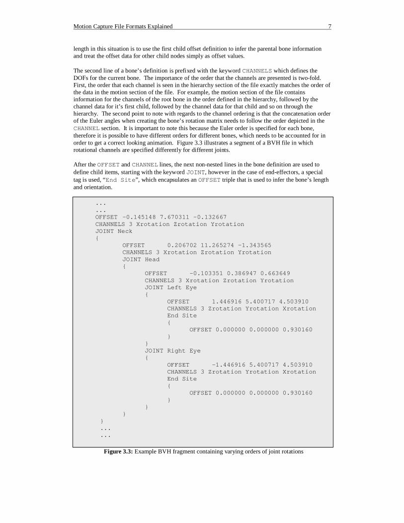
length in this situation is to use the first child offset definition to infer the parental bone information and treat the offset data for other child nodes simply as offset values. The second line of a bone’s definition is prefixed with the keyword CHANNELS which defines the DOFs for the current bone. The importance of the order that the channels are presented is two-fold. First, the order that each channel is seen in the hierarchy section of the file exactly matches the order of the data in the motion section of the file. For example, the motion section of the file contains information for the channels of the root bone in the order defined in the hierarchy, followed by the channel data for it’s first child, followed by the channel data for that child and so on through the hierarchy. The second point to note with regards to the channel ordering is that the concatenation order of the Euler angles when creating the bone’s rotation matrix needs to follow the order depicted in the CHANNEL section. It is important to note this because the Euler order is specified for each bone, therefore it is possible to have different orders for different bones, which needs to be accounted for in order to get a correct looking animation. Figure 3.3 illustrates a segment of a BVH file in which rotational channels are specified differently for different joints. After the OFFSET and CHANNEL lines, the next non-nested lines in the bone definition are used to define child items, starting with the keyword JOINT, however in the case of end-effectors, a special tag is used, “End Site”, which encapsulates an OFFSET triple that is used to infer the bone’s length and orientation.
...
... OFFSET -0.145148 7.670311 -0.132667 CHANNELS 3 Xrotation Zrotation Yrotation JOINT Neck {
OFFSET 0.206702 11.265274 -1.343565 CHANNELS 3 Xrotation Zrotation Yrotation JOINT Head { OFFSET -0.103351 0.386947 0.663649 CHANNELS 3 Xrotation Zrotation Yrotation JOINT Left Eye { OFFSET 1.446916 5.400717 4.503910 CHANNELS 3 Zrotation Yrotation Xrotation End Site { OFFSET 0.000000 0.000000 0.930160 } } JOINT Right Eye { OFFSET -1.446916 5.400717 4.503910 CHANNELS 3 Zrotation Yrotation Xrotation End Site { OFFSET 0.000000 0.000000 0.930160 } } }
} ... ...
Figure 3.3: Example BVH fragment containing varying orders of joint rotations
Motion Capture File Formats Explained 8
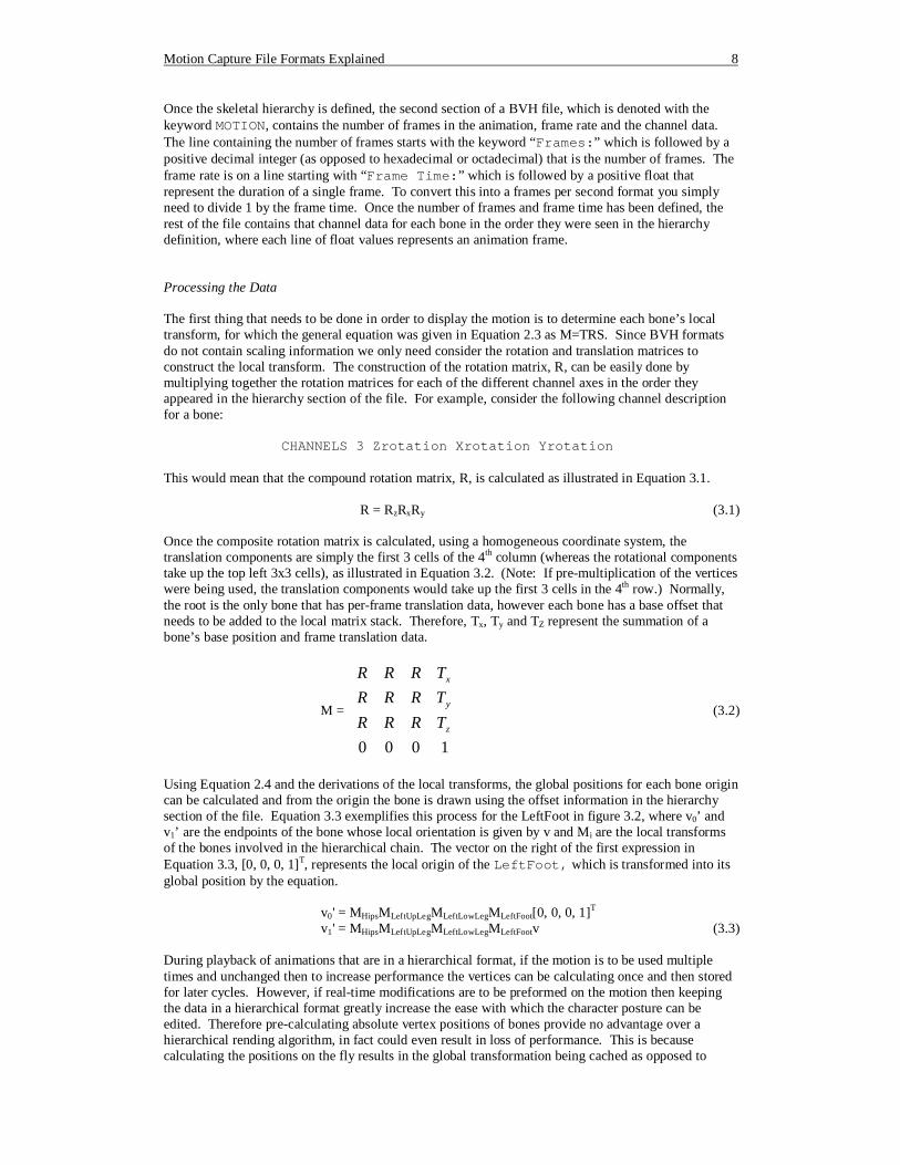
Once the skeletal hierarchy is defined, the second section of a BVH file, which is denoted with the keyword MOTION, contains the number of frames in the animation, frame rate and the channel data. The line containing the number of frames starts with the keyword “Frames:” which is followed by a positive decimal integer (as opposed to hexadecimal or octadecimal) that is the number of frames. The frame rate is on a line starting with “Frame Time:” which is followed by a positive float that represent the duration of a single frame. To convert this into a frames per second format you simply need to divide 1 by the frame time. Once the number of frames and frame time has been defined, the rest of the file contains that channel data for each bone in the order they were seen in the hierarchy definition, where each line of float values represents an animation frame. Processing the Data The first thing that needs to be done in order to display the motion is to determine each bone’s local transform, for which the general equation was given in Equation 2.3 as M=TRS. Since BVH formats do not contain scaling information we only need consider the rotation and translation matrices to construct the local transform. The construction of the rotation matrix, R, can be easily done by multiplying together the rotation matrices for each of the different channel axes in the order they appeared in the hierarchy section of the file. For example, consider the following channel description for a bone: CHANNELS 3 Zrotation Xrotation Yrotation This would mean that the compound rotation matrix, R, is calculated as illustrated in Equation 3.1. R = RzRxRy (3.1) Once the composite rotation matrix is calculated, using a homogeneous coordinate system, the translation components are simply the first 3 cells of the 4th column (whereas the rotational components take up the top left 3x3 cells), as illustrated in Equation 3.2. (Note: If pre-multiplication of the vertices were being used, the translation components would take up the first 3 cells in the 4th row.) Normally, the root is the only bone that has per-frame translation data, however each bone has a base offset that needs to be added to the local matrix stack. Therefore, Tx, Ty and TZ represent the summation of a bone’s base position and frame translation data.
M =
1000z
y
x
TRRRTRRRTRRR
(3.2)
Using Equation 2.4 and the derivations of the local transforms, the global positions for each bone origin can be calculated and from the origin the bone is drawn using the offset information in the hierarchy section of the file. Equation 3.3 exemplifies this process for the LeftFoot in figure 3.2, where v0’ and v1’ are the endpoints of the bone whose local orientation is given by v and Mi are the local transforms of the bones involved in the hierarchical chain. The vector on the right of the first expression in Equation 3.3, [0, 0, 0, 1]T, represents the local origin of the LeftFoot, which is transformed into its global position by the equation. v0' = MHipsMLeftUpLegMLeftLowLegMLeftFoot[0, 0, 0, 1]T v1' = MHipsMLeftUpLegMLeftLowLegMLeftFootv (3.3) During playback of animations that are in a hierarchical format, if the motion is to be used multiple times and unchanged then to increase performance the vertices can be calculating once and then stored for later cycles. However, if real-time modifications are to be preformed on the motion then keeping the data in a hierarchical format greatly increase the ease with which the character posture can be edited. Therefore pre-calculating absolute vertex positions of bones provide no advantage over a hierarchical rending algorithm, in fact could even result in loss of performance. This is because calculating the positions on the fly results in the global transformation being cached as opposed to
Motion Capture File Formats Explained 9
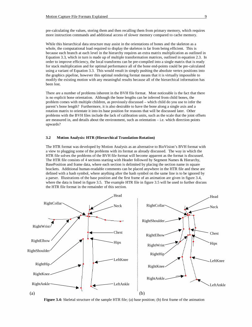
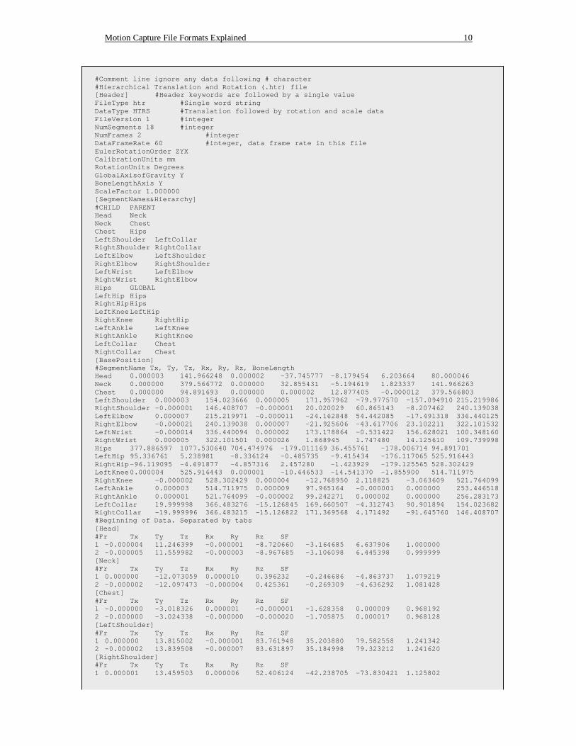
pre-calculating the values, storing them and then recalling them from primary memory, which requires more instruction commands and additional access of slower memory compared to cache memory. While this hierarchical data structure may assist in the orientations of bones and the skeleton as a whole, the computational load required to display the skeleton is far from being efficient. This is because each branch at each level in the hierarchy requires an extra matrix multiplication as outlined in Equation 3.3, which in turn is made up of multiple transformation matrices, outlined in equation 2.3. In order to improve efficiency, the local transforms can be pre-compiled into a single matrix that is ready for stack multiplication and for optimal performance all of the bone end-points could be pre-calculated using a variant of Equation 3.3. This would result in simply pushing the absolute vertex positions into the graphics pipeline, however this optimal rendering format means that it is virtually impossible to modify the existing motion with any meaningful results because all of the hierarchical information has been lost. There are a number of problems inherent in the BVH file format. Most noticeable is the fact that there is no explicit bone orientation. Although the bone lengths can be inferred from child bones, the problem comes with multiple children, as previously discussed – which child do you use to infer the parent’s bone length? Furthermore, it is also desirable to have the bone along a single axis and a rotation matrix to orientate it into its base position for reasons that will be discussed later. Other problems with the BVH files include the lack of calibration units, such as the scale that the joint offsets are measured in, and details about the environment, such as orientation – i.e. which direction points upwards? 3.2 Motion Analysis: HTR (Hierarchical Translation-Rotation) The HTR format was developed by Motion Analysis as an alternative to BioVision’s BVH format with a view to plugging some of the problems with its format as already discussed. The way in which the HTR file solves the problems of the BVH file format will become apparent as the format is discussed. The HTR file consists of 4 sections starting with Header followed by Segment Names & Hierarchy, BasePosition and frame data, where each section is delimited by placing the section name in square brackets. Additional human-readable comments can be placed anywhere in the HTR file and these are defined with a hash symbol, where anything after the hash symbol on the same line is to be ignored by a parser. Illustrations of the base position and the first frame of an animation are given in figure 3.4, where the data is listed in figure 3.5. The example HTR file in figure 3.5 will be used to further discuss the HTR file format in the remainder of this section.
Head
Neck
Chest
Hips
LeftAnkle
LeftKnee
RightCollar
RightWrist
RightElbow
RightShoulder
RightHip
RightAnkle
Head
Neck
Chest
Hips
LeftAnkle
LeftKnee
RightCollar
RightShoulder
RightElbow
RightWrist
RightKnee
RightAnkle
(a) (b)
RightKnee
RightHip
Figure 3.4: Skeletal structure of the sample HTR file; (a) base position; (b) first frame of the animation
Motion Capture File Formats Explained 10
#Comment line ignore any data following # character #Hierarchical Translation and Rotation (.htr) file [Header] #Header keywords are followed by a single value FileType htr #Single word string DataType HTRS #Translation followed by rotation and scale data FileVersion 1 #integer NumSegments 18 #integer NumFrames 2 #integer DataFrameRate 60 #integer, data frame rate in this file EulerRotationOrder ZYX CalibrationUnits mm RotationUnits Degrees GlobalAxisofGravity Y BoneLengthAxis Y ScaleFactor 1.000000 [SegmentNames&Hierarchy] #CHILD PARENT Head Neck Neck Chest Chest Hips LeftShoulder LeftCollar RightShoulder RightCollar LeftElbow LeftShoulder RightElbow RightShoulder LeftWrist LeftElbow RightWrist RightElbow Hips GLOBAL LeftHip Hips RightHip Hips LeftKnee LeftHip RightKnee RightHip LeftAnkle LeftKnee RightAnkle RightKnee LeftCollar Chest RightCollar Chest [BasePosition] #SegmentName Tx, Ty, Tz, Rx, Ry, Rz, BoneLength Head 0.000003 141.966248 0.000002 -37.745777 -8.179454 6.203664 80.000046 Neck 0.000000 379.566772 0.000000 32.855431 -5.194619 1.823337 141.966263 Chest 0.000000 94.891693 0.000000 0.000002 12.877405 -0.000012 379.566803 LeftShoulder 0.000003 154.023666 0.000005 171.957962 -79.977570 -157.094910 215.219986 RightShoulder -0.000001 146.408707 -0.000001 20.020029 60.865143 -8.207462 240.139038 LeftElbow 0.000007 215.219971 -0.000011 -24.162848 54.442085 -17.491318 336.440125 RightElbow -0.000021 240.139038 0.000007 -21.925606 -43.617706 23.102211 322.101532 LeftWrist -0.000014 336.440094 0.000002 173.178864 -0.531422 156.628021 100.348160 RightWrist 0.000005 322.101501 0.000026 1.868945 1.747480 14.125610 109.739998 Hips 377.886597 1077.530640 704.474976 -179.011169 36.455761 -178.006714 94.891701 LeftHip 95.336761 5.238981 -8.336124 -0.485735 -9.415434 -176.117065 525.916443 RightHip -96.119095 -4.691877 -4.857316 2.457280 -1.423929 -179.125565 528.302429 LeftKnee 0.000004 525.916443 0.000001 -10.646533 -14.541370 -1.855900 514.711975 RightKnee -0.000002 528.302429 0.000004 -12.768950 2.118825 -3.063609 521.764099 LeftAnkle 0.000003 514.711975 0.000009 97.965164 -0.000001 0.000000 253.446518 RightAnkle 0.000001 521.764099 -0.000002 99.242271 0.000002 0.000000 256.283173 LeftCollar 19.999998 366.483276 -15.126845 169.660507 -4.312743 90.901894 154.023682 RightCollar -19.999996 366.483215 -15.126822 171.369568 4.171492 -91.645760 146.408707 #Beginning of Data. Separated by tabs [Head] #Fr Tx Ty Tz Rx Ry Rz SF 1 -0.000004 11.246399 -0.000001 -8.720660 -3.164685 6.637906 1.000000 2 -0.000005 11.559982 -0.000003 -8.967685 -3.106098 6.445398 0.999999 [Neck] #Fr Tx Ty Tz Rx Ry Rz SF 1 0.000000 -12.073059 0.000010 0.396232 -0.246686 -4.863737 1.079219 2 -0.000002 -12.097473 -0.000004 0.425361 -0.269309 -4.636292 1.081428 [Chest] #Fr Tx Ty Tz Rx Ry Rz SF 1 -0.000000 -3.018326 0.000001 -0.000001 -1.628358 0.000009 0.968192 2 -0.000000 -3.024338 -0.000000 -0.000020 -1.705875 0.000017 0.968128 [LeftShoulder] #Fr Tx Ty Tz Rx Ry Rz SF 1 0.000000 13.815002 -0.000001 83.761948 35.203880 79.582558 1.241342 2 -0.000002 13.839508 -0.000007 83.631897 35.184998 79.323212 1.241620 [RightShoulder] #Fr Tx Ty Tz Rx Ry Rz SF 1 0.000001 13.459503 0.000006 52.406124 -42.238705 -73.830421 1.125802
Motion Capture File Formats Explained 11
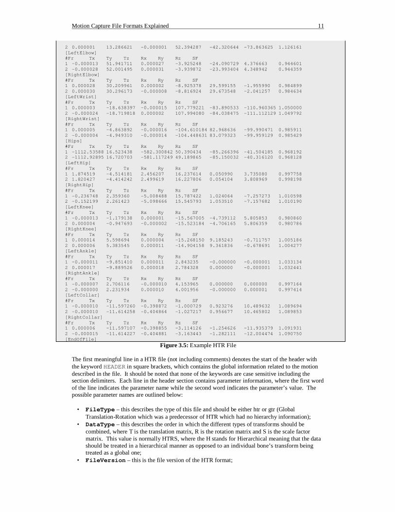
2 0.000001 13.286621 -0.000001 52.394287 -42.320644 -73.863625 1.126161 [LeftElbow] #Fr Tx Ty Tz Rx Ry Rz SF 1 -0.000013 51.941711 0.000027 -3.925248 -24.090729 4.376663 0.944601 2 -0.000028 52.001495 0.000031 -3.939872 -23.993404 4.348942 0.944359 [RightElbow] #Fr Tx Ty Tz Rx Ry Rz SF 1 0.000028 30.209961 0.000002 -8.925378 29.599155 -1.955990 0.984899 2 0.000030 30.296173 -0.000008 -8.816924 29.673548 -2.041257 0.984634 [LeftWrist] #Fr Tx Ty Tz Rx Ry Rz SF 1 0.000003 -18.638397 -0.000015 107.779221 -83.890533 -110.960365 1.050000 2 -0.000024 -18.719818 0.000002 107.994080 -84.038475 -111.112129 1.049792 [RightWrist] #Fr Tx Ty Tz Rx Ry Rz SF 1 0.000005 -4.863892 -0.000016 -104.610184 82.968636 -99.990471 0.985911 2 -0.000004 -4.949310 -0.000014 -104.448631 83.079323 -99.959129 0.985429 [Hips] #Fr Tx Ty Tz Rx Ry Rz SF 1 -1112.53588 16.523438 -582.300842 50.390434 -85.266396 -41.504185 0.968192 2 -1112.92895 16.720703 -581.117249 49.189865 -85.150032 -40.316120 0.968128 [LeftHip] #Fr Tx Ty Tz Rx Ry Rz SF 1 1.874519 -4.514181 2.456207 16.237614 0.050990 3.735080 0.997758 2 1.820427 -4.414242 2.499619 16.227806 0.054104 3.808969 0.998198 [RightHip] #Fr Tx Ty Tz Rx Ry Rz SF 1 -0.236748 2.359360 -5.008488 15.787422 1.024064 -7.257273 1.010598 2 -0.152199 2.261423 -5.098666 15.545793 1.053510 -7.157682 1.010190 [LeftKnee] #Fr Tx Ty Tz Rx Ry Rz SF 1 -0.000013 -1.179138 0.000001 -15.567005 -4.739112 5.805853 0.980860 2 0.000004 -0.947693 -0.000002 -15.523184 -4.706165 5.806359 0.980786 [RightKnee] #Fr Tx Ty Tz Rx Ry Rz SF 1 0.000014 5.598694 0.000004 -15.268150 9.185243 -0.711757 1.005186 2 0.000006 5.383545 0.000011 -14.904158 9.361836 -0.678691 1.004277 [LeftAnkle] #Fr Tx Ty Tz Rx Ry Rz SF 1 -0.000011 -9.851410 0.000011 2.843235 -0.000000 -0.000001 1.033134 2 0.000017 -9.889526 0.000018 2.784328 0.000000 -0.000001 1.032441 [RightAnkle] #Fr Tx Ty Tz Rx Ry Rz SF 1 -0.000007 2.706116 -0.000010 4.153965 0.000000 0.000000 0.997164 2 -0.000000 2.231934 0.000010 4.001956 -0.000000 0.000001 0.997414 [LeftCollar] #Fr Tx Ty Tz Rx Ry Rz SF 1 -0.000010 -11.597260 -0.398872 -1.000729 0.923276 10.489632 1.089694 2 -0.000010 -11.614258 -0.404864 -1.027217 0.956677 10.465802 1.089853 [RightCollar] #Fr Tx Ty Tz Rx Ry Rz SF 1 0.000006 -11.597107 -0.398855 -3.114126 -1.254626 -11.935379 1.091931 2 -0.000015 -11.614227 -0.404881 -3.163443 -1.282111 -12.004474 1.090750 [EndOfFile]
Figure 3.5: Example HTR File The first meaningful line in a HTR file (not including comments) denotes the start of the header with the keyword HEADER in square brackets, which contains the global information related to the motion described in the file. It should be noted that none of the keywords are case sensitive including the section delimiters. Each line in the header section contains parameter information, where the first word of the line indicates the parameter name while the second word indicates the parameter’s value. The possible parameter names are outlined below:
• FileType – this describes the type of this file and should be either htr or gtr (Global Translation-Rotation which was a predecessor of HTR which had no hierarchy information);
• DataType – this describes the order in which the different types of transforms should be combined, where T is the translation matrix, R is the rotation matrix and S is the scale factor matrix. This value is normally HTRS, where the H stands for Hierarchical meaning that the data should be treated in a hierarchical manner as opposed to an individual bone’s transform being treated as a global one;
• FileVersion – this is the file version of the HTR format;
Motion Capture File Formats Explained 12
• NumSegments – this indicates the number of bones in the skeleton; • NumFrames – this indicates the number of frames in the animation; • DataFrameRate – this indicates the frame rate of the animation in frames per second; • EulerRotationOrder – this describes the order in which the x, y, z rotation values should be
combined; • CalibrationUnits – this defines the metric used to measure the translation units, i.e. inches,
millimetres, centimetres, metres, etc; • RotationUnits – this defines the metric used to measure the rotation angles, which are
normally “Degrees”, however can be “Radians”; • GlobalAxisofGravity – this specifies the global “up axis” of the data, which is normally
the positive y-axis; • BoneLengthAxis – this indicates the direction/axis that all the bone lengths are aligned to,
which is normally the y-axis (and if omitted from the specification is to be assumed to be the y-axis);
• ScaleFactor – this is a global scale factor that is to be applied to the complete motion.
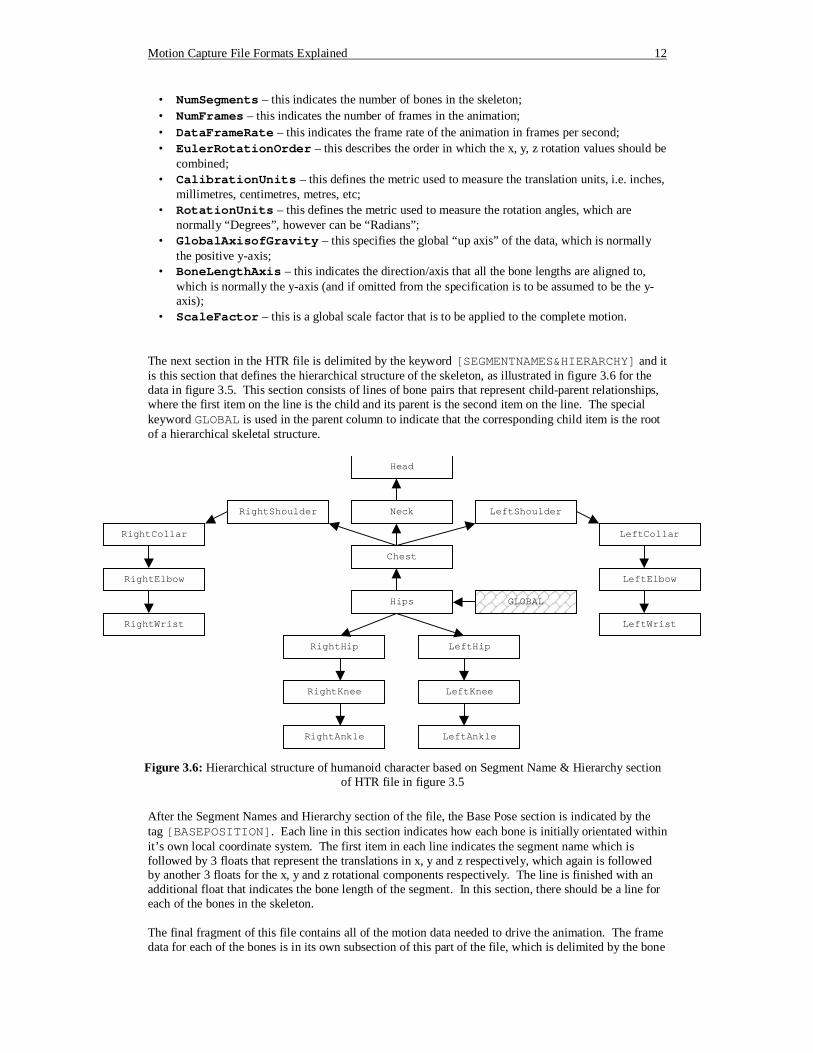
The next section in the HTR file is delimited by the keyword [SEGMENTNAMES&HIERARCHY] and it is this section that defines the hierarchical structure of the skeleton, as illustrated in figure 3.6 for the data in figure 3.5. This section consists of lines of bone pairs that represent child-parent relationships, where the first item on the line is the child and its parent is the second item on the line. The special keyword GLOBAL is used in the parent column to indicate that the corresponding child item is the root of a hierarchical skeletal structure.
After the Segment Names and Hierarchy section of the file, the Base Pose section is indicated by the tag [BASEPOSITION]. Each line in this section indicates how each bone is initially orientated within it’s own local coordinate system. The first item in each line indicates the segment name which is followed by 3 floats that represent the translations in x, y and z respectively, which again is followed by another 3 floats for the x, y and z rotational components respectively. The line is finished with an additional float that indicates the bone length of the segment. In this section, there should be a line for each of the bones in the skeleton. The final fragment of this file contains all of the motion data needed to drive the animation. The frame data for each of the bones is in its own subsection of this part of the file, which is delimited by the bone
Hips
RightShoulder
GLOBAL
RightHip LeftHip
RightKnee LeftKnee
RightAnkle LeftAnkle
Chest
Neck
Head
LeftShoulder
RightCollar LeftCollar
RightElbow LeftElbow
RightWrist LeftWrist
Figure 3.6: Hierarchical structure of humanoid character based on Segment Name & Hierarchy section
of HTR file in figure 3.5
Motion Capture File Formats Explained 13
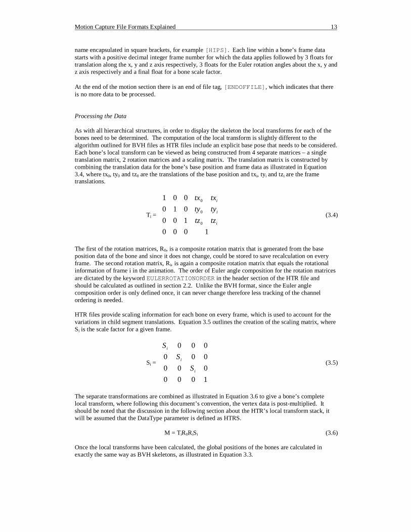
name encapsulated in square brackets, for example [HIPS]. Each line within a bone’s frame data starts with a positive decimal integer frame number for which the data applies followed by 3 floats for translation along the x, y and z axis respectively, 3 floats for the Euler rotation angles about the x, y and z axis respectively and a final float for a bone scale factor. At the end of the motion section there is an end of file tag, [ENDOFFILE], which indicates that there is no more data to be processed. Processing the Data As with all hierarchical structures, in order to display the skeleton the local transforms for each of the bones need to be determined. The computation of the local transform is slightly different to the algorithm outlined for BVH files as HTR files include an explicit base pose that needs to be considered. Each bone’s local transform can be viewed as being constructed from 4 separate matrices – a single translation matrix, 2 rotation matrices and a scaling matrix. The translation matrix is constructed by combining the translation data for the bone’s base position and frame data as illustrated in Equation 3.4, where tx0, ty0 and tz0 are the translations of the base position and txi, tyi and tzi are the frame translations.
Ti =
+++
1000100010001
0
0
0
i
i
i
tztztytytxtx
(3.4)
The first of the rotation matrices, R0, is a composite rotation matrix that is generated from the base position data of the bone and since it does not change, could be stored to save recalculation on every frame. The second rotation matrix, Ri, is again a composite rotation matrix that equals the rotational information of frame i in the animation. The order of Euler angle composition for the rotation matrices are dictated by the keyword EULERROTATIONORDER in the header section of the HTR file and should be calculated as outlined in section 2.2. Unlike the BVH format, since the Euler angle composition order is only defined once, it can never change therefore less tracking of the channel ordering is needed. HTR files provide scaling information for each bone on every frame, which is used to account for the variations in child segment translations. Equation 3.5 outlines the creation of the scaling matrix, where Si is the scale factor for a given frame.
Si =
1000000000000
i
i
i
SS
S
(3.5)
The separate transformations are combined as illustrated in Equation 3.6 to give a bone’s complete local transform, where following this document’s convention, the vertex data is post-multiplied. It should be noted that the discussion in the following section about the HTR’s local transform stack, it will be assumed that the DataType parameter is defined as HTRS.
M = TiR0RiSi (3.6) Once the local transforms have been calculated, the global positions of the bones are calculated in exactly the same way as BVH skeletons, as illustrated in Equation 3.3.
Motion Capture File Formats Explained 14
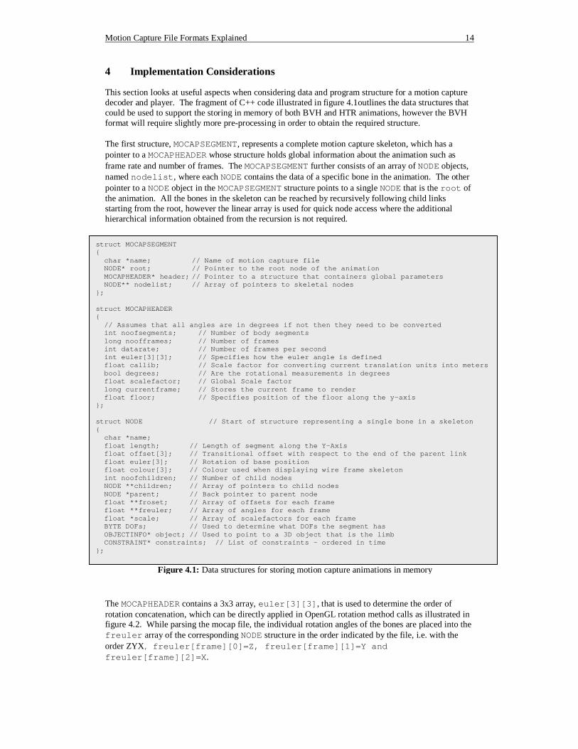
4 Implementation Considerations This section looks at useful aspects when considering data and program structure for a motion capture decoder and player. The fragment of C++ code illustrated in figure 4.1outlines the data structures that could be used to support the storing in memory of both BVH and HTR animations, however the BVH format will require slightly more pre-processing in order to obtain the required structure. The first structure, MOCAPSEGMENT, represents a complete motion capture skeleton, which has a pointer to a MOCAPHEADER whose structure holds global information about the animation such as frame rate and number of frames. The MOCAPSEGMENT further consists of an array of NODE objects, named nodelist, where each NODE contains the data of a specific bone in the animation. The other pointer to a NODE object in the MOCAPSEGMENT structure points to a single NODE that is the root of the animation. All the bones in the skeleton can be reached by recursively following child links starting from the root, however the linear array is used for quick node access where the additional hierarchical information obtained from the recursion is not required.
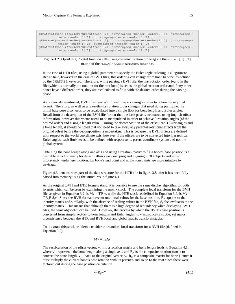
The MOCAPHEADER contains a 3x3 array, euler[3][3], that is used to determine the order of rotation concatenation, which can be directly applied in OpenGL rotation method calls as illustrated in figure 4.2. While parsing the mocap file, the individual rotation angles of the bones are placed into the freuler array of the corresponding NODE structure in the order indicated by the file, i.e. with the order ZYX, freuler[frame][0]=Z, freuler[frame][1]=Y and freuler[frame][2]=X.
struct MOCAPSEGMENT { char *name; // Name of motion capture file NODE* root; // Pointer to the root node of the animation MOCAPHEADER* header; // Pointer to a structure that containers global parameters NODE** nodelist; // Array of pointers to skeletal nodes }; struct MOCAPHEADER { // Assumes that all angles are in degrees if not then they need to be converted int noofsegments; // Number of body segments long noofframes; // Number of frames int datarate; // Number of frames per second int euler[3][3]; // Specifies how the euler angle is defined float callib; // Scale factor for converting current translation units into meters bool degrees; // Are the rotational measurements in degrees float scalefactor; // Global Scale factor long currentframe; // Stores the current frame to render float floor; // Specifies position of the floor along the y-axis }; struct NODE // Start of structure representing a single bone in a skeleton { char *name; float length; // Length of segment along the Y-Axis float offset[3]; // Transitional offset with respect to the end of the parent link float euler[3]; // Rotation of base position float colour[3]; // Colour used when displaying wire frame skeleton int noofchildren; // Number of child nodes NODE **children; // Array of pointers to child nodes NODE *parent; // Back pointer to parent node float **froset; // Array of offsets for each frame float **freuler; // Array of angles for each frame float *scale; // Array of scalefactors for each frame BYTE DOFs; // Used to determine what DOFs the segment has OBJECTINFO* object; // Used to point to a 3D object that is the limb CONSTRAINT* constraints; // List of constraints - ordered in time };
Figure 4.1: Data structures for storing motion capture animations in memory
Motion Capture File Formats Explained 15
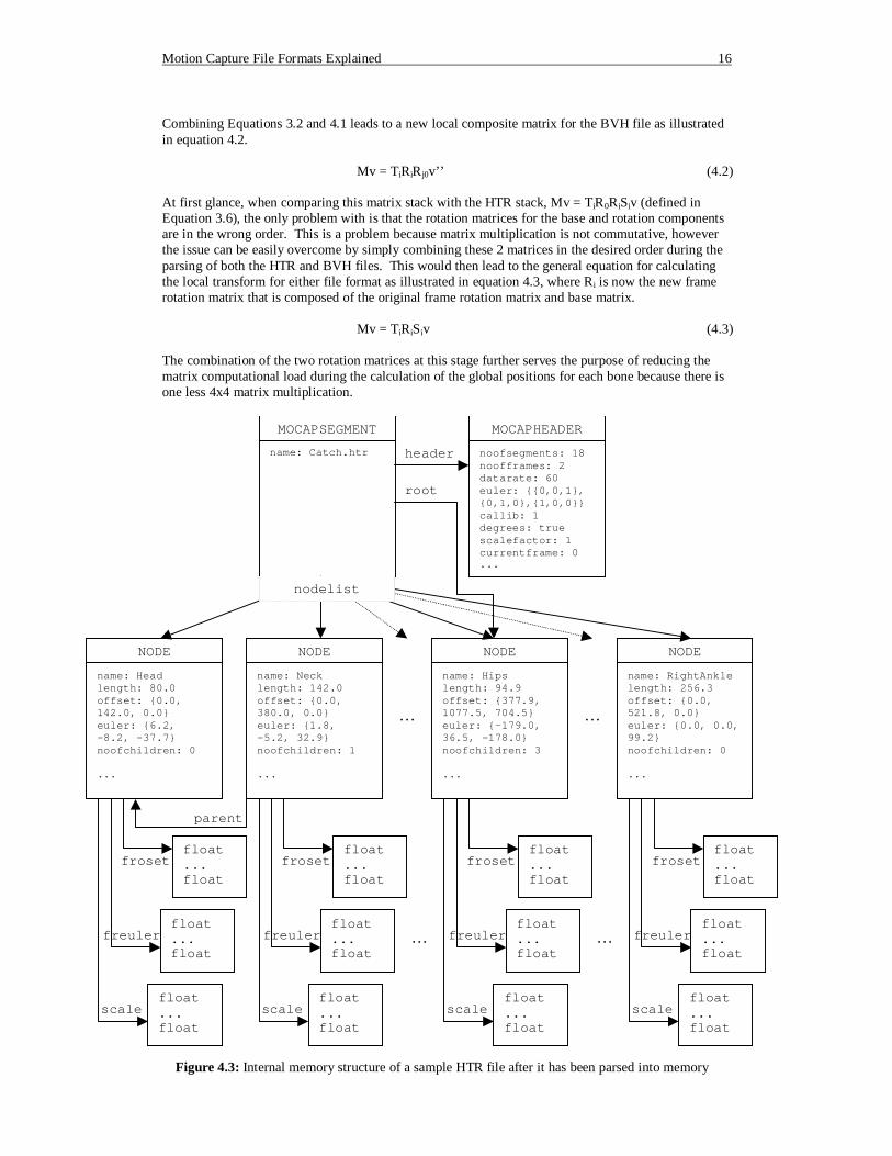
In the case of HTR files, using a global parameter to specify the Euler angle ordering is a legitimate step to take, however in the case of BVH files, this ordering can change from bone to bone, as defined by the CHANNEL keyword. Therefore, while parsing a BVH file, the first rotation order found in the file (which is normally the rotation for the root bone) is set as the global rotation order and if any other bones have a different order, they are recalculated to fit in with the desired order during the parsing phase. As previously mentioned, BVH files need additional pre-processing in order to obtain the required format. Therefore, as well as any on-the-fly rotation order changes that need doing per frame, the initial base pose also needs to be recalculated into a single float for bone length and Euler angles. Recall from the description of the BVH file format that the base pose is structured using implicit offset information, however this vector needs to be manipulated in order to achieve 3 rotation angles (of the desired order) and a single length value. During the decomposition of the offset into 3 Euler angles and a bone length, it should be noted that you need to take away any parental rotational effects from the original offset before the decomposition is undertaken. This is because the BVH offsets are defined with respect to the world coordinate axis, however if the offsets are to be converted into hierarchical Euler angles, each limb needs to be defined with respect to its parent coordinate system and not the global system. Obtaining the bone length along one axis and using a rotation matrix to fix a bone’s base position is a desirable effect on many levels as it allows easy mapping and aligning to 3D objects and more importantly, under any rotation, the bone’s end point and angle constraints are more intuitive to envisage. Figure 4.3 demonstrates part of the data structure for the HTR file in figure 3.5 after it has been fully parsed into memory using the structures in figure 4.1. As the original BVH and HTR formats stand, it is possible to use the same display algorithm for both formats which can be seen by examining the matrix stack. The complete local transform for the BVH file, as given in Equation 3.2, is Mv = TiRiv, while the HTR stack, as defined in Equation 3.6, is Mv = TiR0RiSiv. Since the BVH format have no rotational values for the base position, R0 equates to the identity matrix and similarly, with the absence of scaling values in the BVH file, Si also evaluates to the identity matrix. This means that although there is a high degree of redundancy when displaying BVH files, the same algorithm can be used. However, the process by which the BVH’s base position is converted from simple vectors to bone lengths and Euler angles now introduces a subtle, yet major inconsistency between the HTR and BVH local and global matrix transform stacks. To illustrate this stack problem, consider the standard local transform for a BVH file (defined in Equation 3.2): Mv = TiRiv The recalculation of the offset vector, v, into a rotation matrix and bone length leads to Equation 4.1, where v’’ represents the bone length along a single axis and Rj0 is the composite rotation matrix to convert the bone length, v’’, back to the original vector, v. Rj0 is a composite matrix for bone j, since it must multiply the current bone’s base rotation with its parent’s and so on to the root since these were factored out during the base position calculation. v=Rj0v’’ (4.1)
glRotatef(node->freuler[currentframe][0], curmocapseg->header->euler[0][0], curmocapseg-> header->euler[0][1], curmocapseg->header->euler[0][2]);
glRotatef(node->freuler[currentframe][1], curmocapseg->header->euler[1][0], curmocapseg-> header->euler[1][1], curmocapseg->header->euler[1][2]);
glRotatef(node->freuler[currentframe][2], curmocapseg->header->euler[2][0], curmocapseg-> header->euler[2][1], curmocapseg->header->euler[2][2]);
Figure 4.2: OpenGL glRotatef function calls using dynamic rotation ordering via the euler[3][3]
matrix of the MOCAPHEADER structure, header.
Motion Capture File Formats Explained 16
Combining Equations 3.2 and 4.1 leads to a new local composite matrix for the BVH file as illustrated in equation 4.2.
Mv = TiRiRj0v’’ (4.2) At first glance, when comparing this matrix stack with the HTR stack, Mv = TiR0RiSiv (defined in Equation 3.6), the only problem with is that the rotation matrices for the base and rotation components are in the wrong order. This is a problem because matrix multiplication is not commutative, however the issue can be easily overcome by simply combining these 2 matrices in the desired order during the parsing of both the HTR and BVH files. This would then lead to the general equation for calculating the local transform for either file format as illustrated in equation 4.3, where Ri is now the new frame rotation matrix that is composed of the original frame rotation matrix and base matrix.
Mv = TiRiSiv (4.3) The combination of the two rotation matrices at this stage further serves the purpose of reducing the matrix computational load during the calculation of the global positions for each bone because there is one less 4x4 matrix multiplication.
MOCAPSEGMENT name: Catch.htr
MOCAPHEADER noofsegments: 18 noofframes: 2 datarate: 60 euler: {{0,0,1}, {0,1,0},{1,0,0}} callib: 1 degrees: true scalefactor: 1 currentframe: 0 ...
NODE name: Head length: 80.0 offset: {0.0, 142.0, 0.0} euler: {6.2, -8.2, -37.7} noofchildren: 0 ...
NODE name: Neck length: 142.0 offset: {0.0, 380.0, 0.0} euler: {1.8, -5.2, 32.9} noofchildren: 1 ...
NODE name: Hips length: 94.9 offset: {377.9, 1077.5, 704.5} euler: {-179.0, 36.5, -178.0} noofchildren: 3 ...
NODE name: RightAnkle length: 256.3 offset: {0.0, 521.8, 0.0} euler: {0.0, 0.0, 99.2} noofchildren: 0 ...
… …
nodelist
root
header
parent
float ... float
froset
float ... float
freuler
float ... float
scale
float ... float
froset
float ... float
freuler
float ... float
scale
float ... float
froset
float ... float
freuler
float ... float
scale
float ... float
froset
float ... float
freuler
float ... float
scale
… …
Figure 4.3: Internal memory structure of a sample HTR file after it has been parsed into memory
Motion Capture File Formats Explained 17
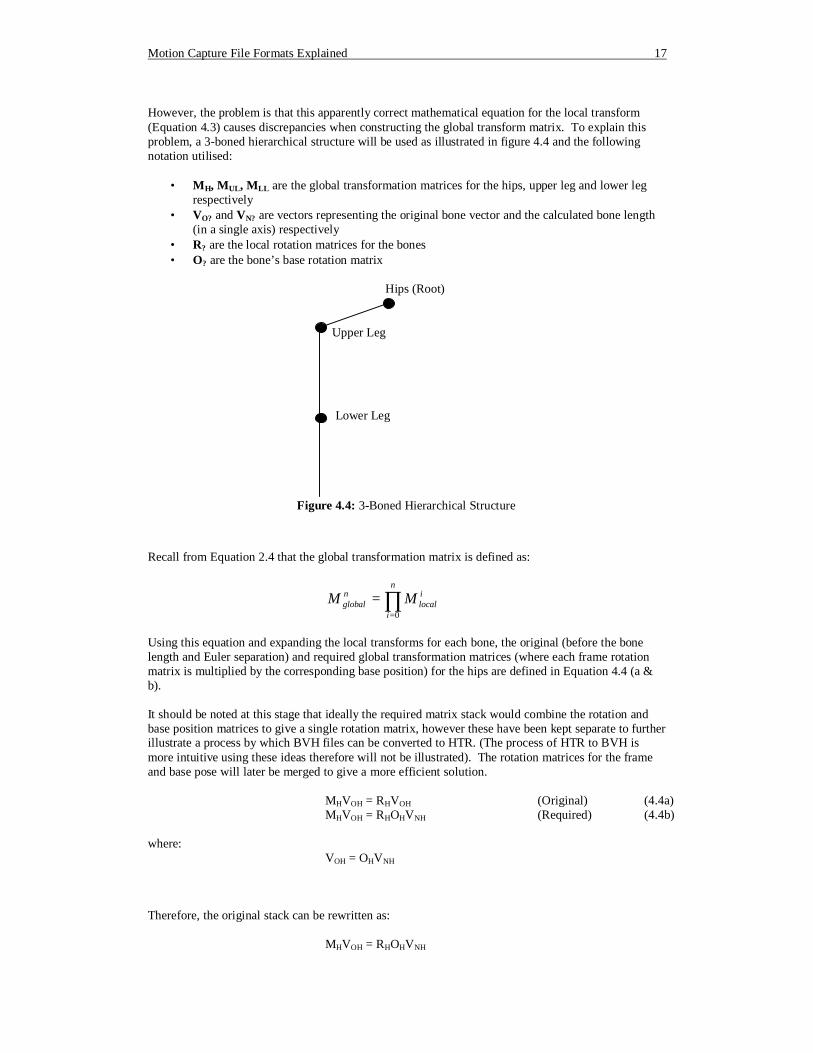
However, the problem is that this apparently correct mathematical equation for the local transform (Equation 4.3) causes discrepancies when constructing the global transform matrix. To explain this problem, a 3-boned hierarchical structure will be used as illustrated in figure 4.4 and the following notation utilised:
• MH, MUL, MLL are the global transformation matrices for the hips, upper leg and lower leg respectively
• VO? and VN? are vectors representing the original bone vector and the calculated bone length (in a single axis) respectively
• R? are the local rotation matrices for the bones • O? are the bone’s base rotation matrix
Recall from Equation 2.4 that the global transformation matrix is defined as:
∏=
=n
i
ilocal
nglobal MM
0
Using this equation and expanding the local transforms for each bone, the original (before the bone length and Euler separation) and required global transformation matrices (where each frame rotation matrix is multiplied by the corresponding base position) for the hips are defined in Equation 4.4 (a & b). It should be noted at this stage that ideally the required matrix stack would combine the rotation and base position matrices to give a single rotation matrix, however these have been kept separate to further illustrate a process by which BVH files can be converted to HTR. (The process of HTR to BVH is more intuitive using these ideas therefore will not be illustrated). The rotation matrices for the frame and base pose will later be merged to give a more efficient solution. MHVOH = RHVOH (Original) (4.4a) MHVOH = RHOHVNH (Required) (4.4b) where: VOH = OHVNH Therefore, the original stack can be rewritten as: MHVOH = RHOHVNH
Hips (Root)
Upper Leg
Lower Leg
Figure 4.4: 3-Boned Hierarchical Structure
Motion Capture File Formats Explained 18
This is the same as the required stack so at this point all looks good. Now we shall consider the global transformations for the upper leg, which is defined as: MULVOUL = RHRULVOUL (Original) MULVOUL = RHOHRULOULVNUL (Required) where: VOUL = OHOULVNUL Substituting this into the equation for the original stack gives: MULVOUL = RHRULOHOULVNUL However, equating this equation with the required global stack for the upper leg soon reveals a consistency problem as illustrated:
MULVOUL = RHRULOHOULVNUL = RHOHRULOULVNUL => RULOH = OHRUL
Since matrix multiplication is not commutative, it is not possible that RULOH = OHRUL, therefore this illustrates the need for the recalculation of each bone’s frame rotation matrix. Using N? to represent the frame rotation matrix for the required matrix stack, the following relationship can be established between this and the original stack for the upper leg:
MULVOUL = RHRULOHOULVNUL = NHOHNULOULVNUL => RULOH = OHNUL (From the definition of global hips transform, RH = NH) => O-1
HRULOH = NUL Therefore in order to structure the data into the required format, each rotation matrix for each frame for the upper leg needs to be calculated according to Equation 4.5. NUL = O-1
HRULOH (4.5) Next we will consider the same problem with the next bone down in the hierarchy, the lower leg, which has matrix stack equations: MULVOUL = RHRULRLLVOLL (Original) MULVOUL = NHOHNULOULNLLOLLVNLL (Required) where: VOUL = OHOULOLLVNLL => RHRULRLLOHOULOLLVNLL = NHOHNULOULNLLOLLVNLL (4.6) From previous hierarchical definitions: RH = NH RUL = OHNULO-1
H Substituting these into equation 4.6 gives: NHOHNULO-1
HRLLOHOULOLLVNLL = NHOHNULOULNLLOLLVNLL => O-1
HRLLOHOUL = OULNLL => O-1
ULO-1HRLLOHOUL = NLL (4.7)
Again, as you would expected, the original and required matrix stacks do not equal each other therefore in order to use the required stack format, all the rotation matrices for each frame for the lower leg need to be recalculated as outlined in Equation 4.7.
Motion Capture File Formats Explained 19
At this point a pattern emerges from for the recalculation step, which does in fact hold for any bone in the hierarchical structure, and is generalised in equation 4.8, where n is the current bone whose parent is n-1 and n=0 is the bone at the root of the hierarchy.
= ∏∏
−
=−=
−1
0
0
1
1n
iin
niin ORON (4.8)
Up to this point, the frame rotation and base position matrices have been kept separate, however as previously mentioned, it would be more advantageous to combine these two into a single frame rotation matrix. This process simply requires the additional post-multiplication of On to Equation 4.8, resulting in Equation 4.9.
= ∏∏
=−=
−n
iin
niin ORON
0
0
1
1 (4.9)
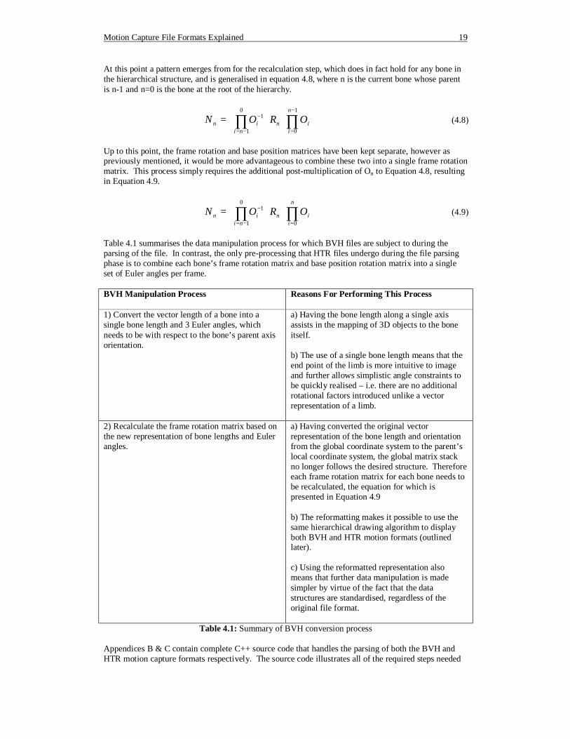
Table 4.1 summarises the data manipulation process for which BVH files are subject to during the parsing of the file. In contrast, the only pre-processing that HTR files undergo during the file parsing phase is to combine each bone’s frame rotation matrix and base position rotation matrix into a single set of Euler angles per frame.
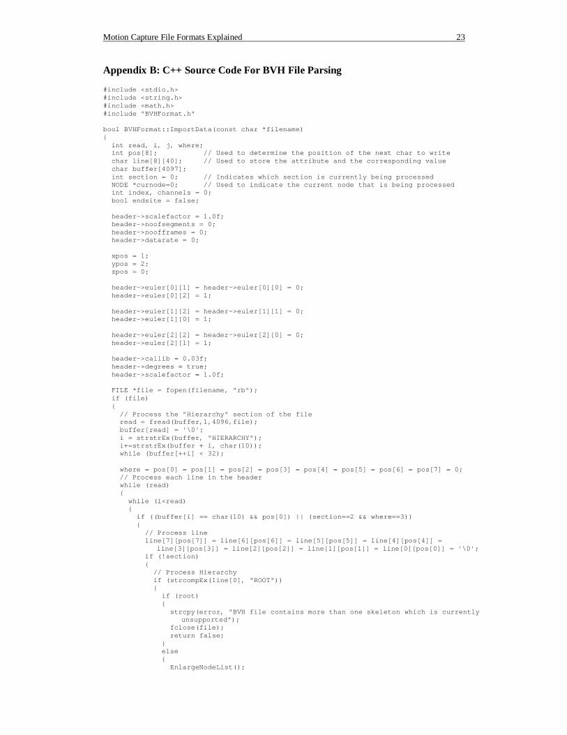
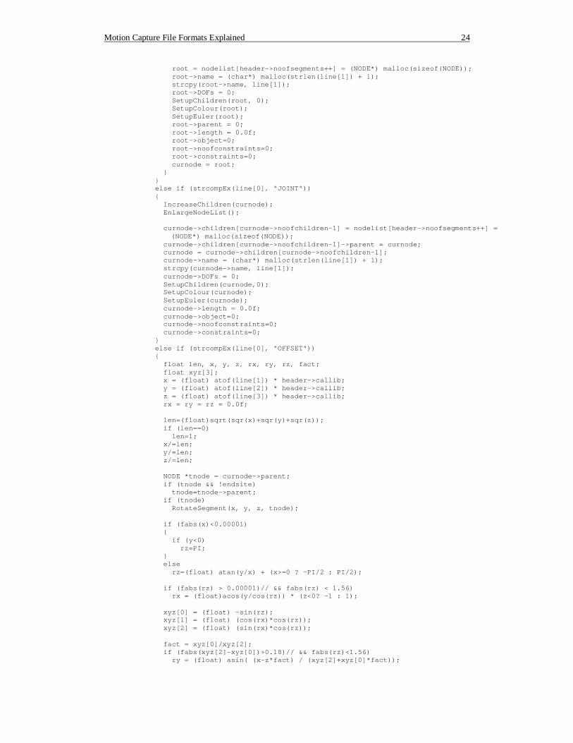
Table 4.1: Summary of BVH conversion process Appendices B & C contain complete C++ source code that handles the parsing of both the BVH and HTR motion capture formats respectively. The source code illustrates all of the required steps needed
BVH Manipulation Process Reasons For Performing This Process
1) Convert the vector length of a bone into a single bone length and 3 Euler angles, which needs to be with respect to the bone’s parent axis orientation.
a) Having the bone length along a single axis assists in the mapping of 3D objects to the bone itself. b) The use of a single bone length means that the end point of the limb is more intuitive to image and further allows simplistic angle constraints to be quickly realised – i.e. there are no additional rotational factors introduced unlike a vector representation of a limb.
2) Recalculate the frame rotation matrix based on the new representation of bone lengths and Euler angles.
a) Having converted the original vector representation of the bone length and orientation from the global coordinate system to the parent’s local coordinate system, the global matrix stack no longer follows the desired structure. Therefore each frame rotation matrix for each bone needs to be recalculated, the equation for which is presented in Equation 4.9 b) The reformatting makes it possible to use the same hierarchical drawing algorithm to display both BVH and HTR motion formats (outlined later). c) Using the reformatted representation also means that further data manipulation is made simpler by virtue of the fact that the data structures are standardised, regardless of the original file format.
Motion Capture File Formats Explained 20
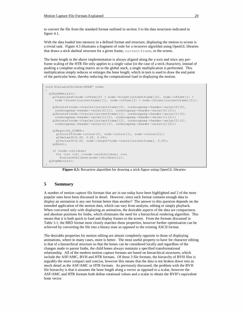
to convert the file from the standard format outlined in section 3 to the data structures indicated in figure 4.1. With the data loaded into memory in a defined format and structure, displaying the motion to screen is a trivial task. Figure 4.5 illustrates a fragment of code for a recursive algorithm using OpenGL libraries that draws a stick skeletal structure for a given frame, currentframe, to the screen. The bone length in the above implementation is always aligned along the y-axis and since any per-frame scaling of the HTR file only applies to a single value (in the case of a stick character), instead of pushing a complete scaling matrix on to the global stack, a single multiplication is performed. This multiplication simply reduces or enlarges the bone length, which in turn is used to draw the end point of the particular bone, thereby reducing the computational load in displaying the motion.
5 Summary A number of motion capture file formats that are in use today have been highlighted and 2 of the more popular ones have been discussed in detail. However, since each format contains enough data to display an animation is any one format better than another? The answer to this question depends on the intended application of the motion data, which can vary from analysis, editing or simply playback. When concerned only with displaying an animation, the desirable aspects of the data are compactness and absolute positions for limbs, which eliminates the need for a hierarchical rendering algorithm. This means that it is both quick to load and display frames to the screen. From the formats discussed in Table 3.1, the BRD format most closely matches these properties, however further optimisation can be achieved by converting the file into a binary state as opposed to the existing ASCII format. The desirable properties for motion editing are almost completely opposite to those of displaying animations, where in many cases, more is better. The most useful property to have for character editing is that of a hierarchical structure so that the bones can be considered locally and regardless of the changes made to parent limbs, the child bones always maintain a specified transformational relationship. All of the modern motion capture formats are based on hierarchical structures, which include the ASF/AMC, BVH and HTR formats. Of these 3 file formats, the hierarchy of BVH files is arguably the more compact and concise, however this means that the data is not broken down into as much detail as the ASF/AMC or HTR formats. As previously discussed, the problem with the BVH file hierarchy is that it assumes the bone length along a vector as opposed to a scalar, however the ASF/AMC and HTR formats both define rotational values and a scalar to obtain the BVH’s equivalent bone vector.
void EvaluateChildren(NODE* node) { glPushMatrix(); glTranslatef(node->offset[0] + node->froset[currentframe][0], node->offset[1] +
node->froset[currentframe][1], node->offset[2] + node->froset[currentframe][2]); glRotatef(node->freuler[currentframe][0], curmocapseg->header->euler[0][0],
curmocapseg->header->euler[0][1], curmocapseg->header->euler[0][2]); glRotatef(node->freuler[currentframe][1], curmocapseg->header->euler[1][0],
curmocapseg->header->euler[1][1], curmocapseg->header->euler[1][2]); glRotatef(node->freuler[currentframe][2], curmocapseg->header->euler[2][0],
curmocapseg->header->euler[2][1], curmocapseg->header->euler[2][2]); glBegin(GL_LINES); glColor3f(node->colour[0], node->colour[1], node->colour[2]); glVertex3f(0.0f, 0.0f, 0.0f); glVertex3f(0.0f, node->length*node->scale[currentframe], 0.0f); glEnd(); if (node->children) for (int i=0; i<node->noofchildren; i++) EvaluateChildren(node->children[i]); glPopMatrix(); }
Figure 4.5: Recursive algorithm for drawing a stick figure using OpenGL libraries

Motion Capture File Formats Explained 21
After the property of hierarchical data, other properties that could prove useful during motion editing include details about the environment in which the data was captured. Examples of environmental data include the axis of gravity or even more basic properties such as the metric units used. The BVH format fails to capture any of these details, however the HTR format provides a better level of success, while ASC/AMC provides even more data than HTR files by including details about channel limits. With any motion in a hierarchical format, the rendering algorithm needs to reflect this therefore a recursive procedure needs to be implemented to render the animation to the screen. This style of rendering is more costly than simply pushing vertex coordinates into the graphics pipeline, so in many cases once any motion editing has been achieved and no further editing will take place the files can be converted to an optimal version that is used for displaying only. As an additional property to consider for motion editing formats, it would still be advantageous to have the data in a compact format. However at present the formats tend to be in an ASCII based format rather than binary which takes on average 3 times the space of binary data, but al least makes them human readable. A binary format would further assist in the parsing of the file since the large numbers of floats would be represented as their binary representations as opposed to text based which need to be converted into float representations before they are of any use. It should however be noted at this point that byte ordering might be a platform-independence problem with binary formats since Intel-based machines store data using “little-Endian”9, which is in the reverse order of Macintosh machines that use “big-Endian”10. With the ASC/AMC file format being such a good all round format for motion editing, a future revision of this document will contain a greater level of detail regarding its format and techniques to parse the file, similar to that of the presently described BVH and HTR files. Updated version of this document will be posted at http://www.dcs.shef.ac.uk/~mikem under Links → Additional Resources.
9 Little-Endian stores the most significant byte on the right of a word 10 Big-Endian stores the most significant byte on the left of a word
Motion Capture File Formats Explained 22
Appendix A: References & Bibliography A.1 References Max Discreet’s 3D Studio Max & Character Studio, http://www2.discreet.com Maya Alias Wavefront’s Maya 3, http://www.aliaswavefront.com Poser Curious Labs’s Poser 4, http://www.curiouslabs.com/products/poser4 A.2 Bibliography This section only contains references to books and papers that specifically discuss the application of character animation and motion capture data. A detailed list of texts on motion capture modification techniques can be found at http://www.dcs.shef.ac.uk/~mikem. A.2.1 Books Jung, M., Fischer, R., Gleicher, M., Thingvold, J., Bevan, M., “Motion Capture and Editing”, A K Peters, November 2000 Maestri, G., “Digital Character Animation”, New Riders Publishing, 1996 Menache, A., “Understanding Motion Capture for Computer Animation and Video Games”, Morgan Kaufmann, August 1999
The Menache book, “Understanding Motion Capture for Computer Animation and Video Games”, provides a good overview of the topic of motion capture with detailed examples of its application in movies. It also introduces some of the basic mathematical techniques that could be used to manipulate the motion data and a review of some of the popular file formats. While this book does provide a good basis for understanding motion capture, it contains very little information for more experienced people who already have a working knowledge of motion capture, except possibly in defining some motion capture formats. In all, the book is a good starting point for newcomers to the subject, however it lacks finer details for the experienced person.
S. Reese, “3D Studio Max Clay Sculpture, Digitizing, & Motion Capture”, Coriolis Group, August 1997 A.2.2 Papers Bodenheimer, B., Rose, C., Rosenthal, S., Pella, J., “The process of motion capture: Dealing with the data”, Computer Animation and Simulation '97, p. 3-18, 1997
The paper by Bodenheimer et al, “Processing Motion Capture Data to Achieve Positional Accuracy”, provides an in-depth discussion on how the raw motion data is captured which in turn is built into a skeletal structure. The paper also discusses the problem of removing any noise from the signals in order to achieve smooth motion curves for the channels of the skeleton. This paper introduces more advanced topics in the data gathering process of motion capture than Menache, however does expect a certain level of understanding. The mathematics presented in this paper is also more advanced, discussing the use of inverse kinematics to optimise the resulting motion. To sum up, this paper gives an advanced look at the processes involved in the motion capture technique, however it is only one avenue of a broad ranging topic.
Choi, K., Park, S., Ko, H., “Processing Motion Capture Data to Achieve Positional Accuracy”, Graphical Models and Image Processing 61: 260-273, 1999 Magnenat-Thalmann, N., Thalmann, D., “Modelling and Motion Capture Techniques for Virtual Environments: International Workshop”, Captech'98, Geneva, Switzerland, November 26-27, 1998 Yu, Q., Terzopoulos, D., “Synthetic Motion Capture for Interactive Virtual Worlds”, Computer Animation, p. 2-10, June 8-10, 1998
Motion Capture File Formats Explained 23
Appendix B: C++ Source Code For BVH File Parsing #include <stdio.h> #include <string.h> #include <math.h> #include "BVHFormat.h" bool BVHFormat::ImportData(const char *filename) { int read, i, j, where; int pos[8]; // Used to determine the position of the next char to write char line[8][40]; // Used to store the attribute and the corresponding value char buffer[4097]; int section = 0; // Indicates which section is currently being processed NODE *curnode=0; // Used to indicate the current node that is being processed int index, channels = 0; bool endsite = false; header->scalefactor = 1.0f; header->noofsegments = 0; header->noofframes = 0; header->datarate = 0; xpos = 1; ypos = 2; zpos = 0; header->euler[0][1] = header->euler[0][0] = 0; header->euler[0][2] = 1; header->euler[1][2] = header->euler[1][1] = 0; header->euler[1][0] = 1; header->euler[2][2] = header->euler[2][0] = 0; header->euler[2][1] = 1; header->callib = 0.03f; header->degrees = true; header->scalefactor = 1.0f; FILE *file = fopen(filename, "rb"); if (file) { // Process the "Hierarchy" section of the file read = fread(buffer,1,4096,file); buffer[read] = '\0'; i = strstrEx(buffer, "HIERARCHY"); i+=strstrEx(buffer + i, char(10)); while (buffer[++i] < 32); where = pos[0] = pos[1] = pos[2] = pos[3] = pos[4] = pos[5] = pos[6] = pos[7] = 0; // Process each line in the header while (read) { while (i<read) { if ((buffer[i] == char(10) && pos[0]) || (section==2 && where==3)) { // Process line line[7][pos[7]] = line[6][pos[6]] = line[5][pos[5]] = line[4][pos[4]] =
line[3][pos[3]] = line[2][pos[2]] = line[1][pos[1]] = line[0][pos[0]] = '\0'; if (!section) { // Process Hierarchy if (strcompEx(line[0], "ROOT")) { if (root) { strcpy(error, "BVH file contains more than one skeleton which is currently
unsupported"); fclose(file); return false; } else { EnlargeNodeList();
Motion Capture File Formats Explained 24
root = nodelist[header->noofsegments++] = (NODE*) malloc(sizeof(NODE)); root->name = (char*) malloc(strlen(line[1]) + 1); strcpy(root->name, line[1]); root->DOFs = 0; SetupChildren(root, 0); SetupColour(root); SetupEuler(root); root->parent = 0; root->length = 0.0f; root->object=0; root->noofconstraints=0; root->constraints=0; curnode = root; } } else if (strcompEx(line[0], "JOINT")) { IncreaseChildren(curnode); EnlargeNodeList(); curnode->children[curnode->noofchildren-1] = nodelist[header->noofsegments++] =
(NODE*) malloc(sizeof(NODE)); curnode->children[curnode->noofchildren-1]->parent = curnode; curnode = curnode->children[curnode->noofchildren-1]; curnode->name = (char*) malloc(strlen(line[1]) + 1); strcpy(curnode->name, line[1]); curnode->DOFs = 0; SetupChildren(curnode,0); SetupColour(curnode); SetupEuler(curnode); curnode->length = 0.0f; curnode->object=0; curnode->noofconstraints=0; curnode->constraints=0; } else if (strcompEx(line[0], "OFFSET")) { float len, x, y, z, rx, ry, rz, fact; float xyz[3]; x = (float) atof(line[1]) * header->callib; y = (float) atof(line[2]) * header->callib; z = (float) atof(line[3]) * header->callib; rx = ry = rz = 0.0f; len=(float)sqrt(sqr(x)+sqr(y)+sqr(z)); if (len==0) len=1; x/=len; y/=len; z/=len; NODE *tnode = curnode->parent; if (tnode && !endsite) tnode=tnode->parent; if (tnode) RotateSegment(x, y, z, tnode); if (fabs(x)<0.00001) { if (y<0) rz=PI; } else rz=(float) atan(y/x) + (x>=0 ? -PI/2 : PI/2); if (fabs(rz) > 0.00001)// && fabs(rz) < 1.56) rx = (float)acos(y/cos(rz)) * (z<0? -1 : 1); xyz[0] = (float) -sin(rz); xyz[1] = (float) (cos(rx)*cos(rz)); xyz[2] = (float) (sin(rx)*cos(rz)); fact = xyz[0]/xyz[2]; if (fabs(xyz[2]-xyz[0])>0.18)// && fabs(rz)<1.56) ry = (float) asin( (x-z*fact) / (xyz[2]+xyz[0]*fact));
Motion Capture File Formats Explained 25
if (!endsite) { float tx, ty, tz; if (curnode!=root && curnode->parent->length==0.0f) { curnode->parent->euler[xpos]=rx*180/PI; curnode->parent->euler[ypos]=ry*180/PI; curnode->parent->euler[zpos]=rz*180/PI; curnode->parent->length = len; float cx=(float) cos(rx), cy=(float) cos(ry), cz=(float) cos(rz); float sx=(float) sin(rx), sy=(float) sin(ry), sz=(float) sin(rz); // Calc Y-1X-1Z-1 to make sure any errors in the rotation are taken care of
in the offset from the parent // Ideal results should be tx=tz=0 and ty=1 float a, b, c, d, e, f, g, h, i; a=cy*cz-sx*sy*sz; b=cy*sz+sx*sy*cz; c=-cx*sy; d=-cx*sz; e=cx*cz; f=sx; g=sy*cz+sx*cy*sz; h=sy*sz-sx*cy*cz; i=cx*cy; tx=a*x+b*y+c*z; ty=d*x+e*y+f*z; tz=g*x+h*y+i*z; SetupOffset(curnode, tx*len, ty*len, tz*len); } else SetupOffset(curnode, x*len, y*len, z*len); } else { curnode->euler[xpos]=rx*180/PI; curnode->euler[ypos]=ry*180/PI; curnode->euler[zpos]=rz*180/PI; curnode->length = len; } } else if (strcompEx(line[0], "CHANNELS") && !endsite) { channels+=atoi(line[1]); int d=2; while (line[d] && d < 8) { if ((line[d][0]&0xdf)=='X') { if ((line[d][1]&0xdf)=='R') curnode->DOFs|=XROT; else if ((line[d][1]&0xdf)=='P') curnode->DOFs|=XTRA; } else if ((line[d][0]&0xdf)=='Y') { if ((line[d][1]&0xdf)=='R') curnode->DOFs|=YROT; else if ((line[d][1]&0xdf)=='P') curnode->DOFs|=YTRA; } else if ((line[d][0]&0xdf)=='Z') { if ((line[d][1]&0xdf)=='R') curnode->DOFs|=ZROT; else if ((line[d][1]&0xdf)=='P') curnode->DOFs|=ZTRA; } ++d; } } else if (strcompEx(line[0], "END") && strcompEx(line[1], "SITE")) endsite = true; else if (line[0][0]=='}')
Motion Capture File Formats Explained 26
{ if (endsite) endsite = false; else curnode = curnode->parent; } else if (strcompEx(line[0], "MOTION")) { rot=0; base = new float**[header->noofsegments]; baseinv = new float**[header->noofsegments]; basestd = new float**[header->noofsegments]; for (int i=0; i<header->noofsegments; i++) { base[i]=0; baseinv[i]=0; basestd[i]=0; } ++section; } } else if (section==1) { // Process Motion if (strcompEx(line[0], "FRAMES:")) { header->noofframes = atoi(line[1]); for (int i=0; i<header->noofsegments; ++i) SetupFrames(nodelist[i], header->noofframes); header->currentframe = 0; } else if (strcompEx(line[0], "FRAME") && strcompEx(line[1], "TIME:")) { header->datarate = (int) (1 / (atof(line[2]))); if ((int) (0.49 + (1 / atof(line[2]))) > header->datarate) ++header->datarate; } if (header->datarate && header->noofframes) { ++section; curnode = root; index = 0; endsite = false; } } else { //Process DOFs if (header->currentframe < header->noofframes) { if (curnode->DOFs == 231) { if (!endsite) { curnode->froset[header->currentframe][0] = (float) atof(line[0]) *
header->callib; curnode->froset[header->currentframe][1] = (float) atof(line[1]) *
header->callib; curnode->froset[header->currentframe][2] = (float) atof(line[2]) *
header->callib; endsite = true; } else { curnode->freuler[header->currentframe][xpos] = (float) atof(line[1]); curnode->freuler[header->currentframe][ypos] = (float) atof(line[2]); curnode->freuler[header->currentframe][zpos] = (float) atof(line[0]); ReCalcRotations(curnode); curnode->scale[header->currentframe] = 1.0f; curnode = nodelist[++index]; endsite = false; } } else { curnode->froset[header->currentframe][0] = curnode->froset[header->
Motion Capture File Formats Explained 27
currentframe][1] = curnode->froset[header->currentframe][2] = 0.0f; curnode->freuler[header->currentframe][xpos] = (float) atof(line[1]); curnode->freuler[header->currentframe][ypos] = (float) atof(line[2]); curnode->freuler[header->currentframe][zpos] = (float) atof(line[0]); ReCalcRotations(curnode); curnode->scale[header->currentframe] = 1.0f; if (index+1 < header->noofsegments) curnode = nodelist[++index]; else { ++header->currentframe; curnode = nodelist[index=0]; } } } else ++section; } if (section!=2) { // Move onto the next line and clear current line information j=strstrEx(buffer + i, char(10)); if (j==-1) { if (buffer[4095]!=10) { read = fread(buffer, 1, 4096, file); i = strstrEx(buffer, char(10)); } else { read = fread(buffer, 1, 4096, file); i=0; } buffer[4096] = '\0'; } else i+=j; } where = pos[0] = pos[1] = pos[2] = pos[3] = pos[4] = pos[5] = pos[6] = pos[7] = 0; } if (buffer[i] > 44 && buffer[i] < 126) line[where][pos[where]++] = buffer[i++]; else if ((buffer[i]==32 || buffer[i]==9) && pos[where]>0) { ++where; ++i; } else ++i; } read = fread(buffer, 1, 4096, file); buffer[4096] = '\0'; i=0; } float num, den; for (i=0; i<header->noofsegments; i++) { // Decompose base pose into ZYX curnode=nodelist[i]; curnode->euler[0]=(float) atan(basestd[i][1][0]/basestd[i][0][0]); if (basestd[i][0][0]<0) if (basestd[i][1][0]<0) curnode->euler[0]-=3.141592f; else curnode->euler[0]+=3.141592f; num=(float) (basestd[i][0][2]*sin(curnode->euler[0])-basestd[i][1][2]*cos(curnode->
euler[0])); den=(float) (-basestd[i][0][1]*sin(curnode->euler[0])+basestd[i][1][1]*cos(curnode->
euler[0])); curnode->euler[2]=(float) atan(num/den)*57.2957795f;
Motion Capture File Formats Explained 28
if (den<0) if (num<0) curnode->euler[2]-=180; else curnode->euler[2]+=180; num=-basestd[i][2][0]; den=(float) (basestd[i][0][0]*cos(curnode->euler[0])+basestd[i][1][0]*sin(curnode->
euler[0])); curnode->euler[1]=(float) atan(num/den)*57.2957795f; if (den<0) if (num<0) curnode->euler[1]-=180; else curnode->euler[1]+=180; curnode->euler[0]*=57.2957795f; } header->callib = 1.0f; header->euler[0][0]=header->euler[0][1]=0; header->euler[0][2]=1; header->euler[1][0]=header->euler[1][2]=0; header->euler[1][1]=1; header->euler[2][1]=header->euler[2][2]=0; header->euler[2][0]=1; fclose(file); return true; } else { strcpy(error, "Cannot Open File"); return false; } } void BVHFormat::IncreaseChildren(NODE* node) { int i; NODE **temp; if (node->children) { // Parent already has children temp = node->children; temp = (NODE**) malloc(sizeof(NODE*) * node->noofchildren); for (i=0; i<node->noofchildren; ++i) temp[i] = node->children[i]; free(node->children); node->children = (NODE**) malloc(sizeof(NODE*) * ++node->noofchildren); for (i=0; i<node->noofchildren; ++i) node->children[i] = temp[i]; free(temp); } else SetupChildren(node, ++node->noofchildren); } bool BVHFormat::ExportData(const char* filename) { strcpy(error, "Data Export for BVH format has not been implemented"); return false; } void BVHFormat::RotateSegment(float &x, float &y, float &z, NODE* tnode) { float nx, ny, nz; if (tnode->parent) RotateSegment(x, y, z, tnode->parent); nx = (float) (cos(-tnode->euler[zpos]*PI/180)*x - sin(-tnode->euler[zpos]*PI/180)*y); ny = (float) (sin(-tnode->euler[zpos]*PI/180)*x + cos(-tnode->euler[zpos]*PI/180)*y); nz = z; x = nx; y = (float) (cos(-tnode->euler[xpos]*PI/180)*ny - sin(-tnode->euler[xpos]*PI/180)*nz); z = (float) (sin(-tnode->euler[xpos]*PI/180)*ny + cos(-tnode->euler[xpos]*PI/180)*nz);
Motion Capture File Formats Explained 29
nx = (float) (cos(-tnode->euler[ypos]*PI/180)*x + sin(-tnode->euler[ypos]*PI/180)*z); ny = y; nz = (float) (-sin(-tnode->euler[ypos]*PI/180)*x + cos(-tnode->euler[ypos]*PI/180)*z); x = nx; y = ny; z = nz; } void BVHFormat::ReCalcRotations(NODE* curnode) { static int activesegment=0; float ang[3]; float num, den; int i; if (!rot) { rot=new float*[3]; arot=new float*[3]; trot=new float*[3]; for (i=0; i<3; i++) { rot[i]=new float[3]; arot[i]=new float[3]; trot[i]=new float[3]; } } if (!base[activesegment]) { base[activesegment]=new float*[3]; baseinv[activesegment]=new float*[3]; basestd[activesegment]=new float*[3]; for (i=0; i<3; i++) { base[activesegment][i]=new float[3]; baseinv[activesegment][i]=new float[3]; basestd[activesegment][i]=new float[3]; } base[activesegment][0][0]=base[activesegment][1][1]=base[activesegment][2][2]=1.0f; base[activesegment][0][1]=base[activesegment][0][2]=0.0f; base[activesegment][1][0]=base[activesegment][1][2]=0.0f; base[activesegment][2][0]=base[activesegment][2][1]=0.0f; baseinv[activesegment][0][0]=baseinv[activesegment][1][1]=baseinv[activesegment][2][2]=1.0f; baseinv[activesegment][0][1]=baseinv[activesegment][0][2]=0.0f; baseinv[activesegment][1][0]=baseinv[activesegment][1][2]=0.0f; baseinv[activesegment][2][0]=baseinv[activesegment][2][1]=0.0f; ang[0]=curnode->euler[xpos]*0.0174532f; ang[1]=curnode->euler[ypos]*0.0174532f; ang[2]=curnode->euler[zpos]*0.0174532f; CalcRotationMatrix(ang, basestd[activesegment], trot, arot, xpos, ypos, false); NODE *tnode=curnode->parent; while (tnode) { ang[0]=tnode->euler[xpos]*0.0174532f; ang[1]=tnode->euler[ypos]*0.0174532f; ang[2]=tnode->euler[zpos]*0.0174532f; CalcRotationMatrix(ang, rot, trot, arot, xpos, ypos, false); matmult(rot, base[activesegment], trot, 3, 3); swap=trot; trot=base[activesegment]; base[activesegment]=swap; ang[0]=-ang[0]; ang[1]=-ang[1]; ang[2]=-ang[2]; CalcRotationMatrix(ang, rot, trot, arot, xpos, ypos, true); matmult(baseinv[activesegment], rot, trot, 3, 3); swap=trot; trot=baseinv[activesegment];

Motion Capture File Formats Explained 30
baseinv[activesegment]=swap; tnode=tnode->parent; } } ang[0]=curnode->freuler[header->currentframe][xpos]*0.0174532f; ang[1]=curnode->freuler[header->currentframe][ypos]*0.0174532f; ang[2]=curnode->freuler[header->currentframe][zpos]*0.0174532f; CalcRotationMatrix(ang, rot, trot, arot, xpos, ypos); matmult(baseinv[activesegment], rot, trot, 3, 3); matmult(trot, base[activesegment], rot, 3, 3); matmult(rot, basestd[activesegment], trot, 3, 3); // Decompose frame data into ZYX curnode->freuler[header->currentframe][0]=(float) atan(trot[1][0]/trot[0][0]); if (trot[0][0]<0) if (trot[1][0]<0) curnode->freuler[header->currentframe][0]-=3.141592f; else curnode->freuler[header->currentframe][0]+=3.141592f; num=(float) (trot[0][2]*sin(curnode->freuler[header->currentframe][0])-trot[1][2]*
cos(curnode->freuler[header->currentframe][0])); den=(float) (-trot[0][1]*sin(curnode->freuler[header->currentframe][0])+
trot[1][1]*cos(curnode->freuler[header->currentframe][0])); curnode->freuler[header->currentframe][2]=(float) atan(num/den)*57.2957795f; if (den<0) if (num<0) curnode->freuler[header->currentframe][2]-=180; else curnode->freuler[header->currentframe][2]+=180; num=-trot[2][0]; den=(float) (trot[0][0]*cos(curnode->freuler[header->currentframe][0])+
trot[1][0]*sin(curnode->freuler[header->currentframe][0])); curnode->freuler[header->currentframe][1]=(float) atan(num/den)*57.2957795f; if (den<0) if (num<0) curnode->freuler[header->currentframe][1]-=180; else curnode->freuler[header->currentframe][1]+=180; curnode->freuler[header->currentframe][0]*=57.2957795f; if (++activesegment>=header->noofsegments) activesegment=0; } BVHFormat::~BVHFormat() { for (int i=0; i<header->noofsegments; i++) { for (int j=0; j<3; j++) { delete[] base[i][j]; delete[] baseinv[i][j]; delete[] basestd[i][j]; } delete[] base[i]; delete[] baseinv[i]; delete[] basestd[i]; } for (int j=0; j<3; j++) { delete[] rot[j]; delete[] arot[j]; delete[] trot[j]; } delete[] base; delete[] baseinv; delete[] basestd; delete[] rot; delete[] arot; delete[] trot; }
Motion Capture File Formats Explained 31
Appendix C: C++ Source Code For HTR File Parsing #include <stdio.h> #include <string.h> #include "HTRFormat.h" bool HTRFormat::ImportData(const char *filename) { int read, i, j, where; int pos[8]; // Used to determine the position of the next char to write char line[8][40]; // Used to store the attribute and the corresponding value char buffer[4097]; int section = 0; // Indicates which section is currently being processed NODE *tnode; // Used when setting up the base positions and frames float **base, **rot, **arot, **trot; float ang[3], num, den; bool eof=false; base=new float*[3]; rot=new float*[3]; arot=new float*[3]; trot=new float*[3]; for (i=0; i<3; i++) { base[i]=new float[3]; rot[i]=new float[3]; arot[i]=new float[3]; trot[i]=new float[3]; } header->callib = 1.0f; header->scalefactor = 1.0f; FILE *file = fopen(filename, "rb"); if (file) { // Process the "Header" section of the file read = fread(buffer,1,4096,file); buffer[read] = '\0'; i = strstrEx(buffer, "[HEADER]"); i+=strstrEx(buffer + i, char(10)); while (buffer[++i] < 32); where = pos[0] = pos[1] = pos[2] = pos[3] = pos[4] = pos[5] = pos[6] = pos[7] = 0; // Process each line in the header while (read && !eof) { while (i<read && !eof) { if (buffer[i] =='#' || buffer[i] == char(10)) { // Process line line[1][pos[1]] = line[0][pos[0]] = '\0'; if (line[0][0]=='[') { if (++section==2) { // Body structure has been read and ready to process the base positions // So assign the GLOBAL node to the root pointer root = 0; for (int j=0; j<currentnode && !root; ++j) { if (strcompEx(nodelist[j]->name, "GLOBAL")) { root = nodelist[j]->children[0]; root->parent=0; NODE **temp = (NODE**) malloc(sizeof(NODE*) * header->noofsegments); int m; for (m=0; m < j; ++m) temp[m] = nodelist[m]; for (m=j+1; m<=header->noofsegments; ++m) temp[m-1] = nodelist[m]; for (m=0; m<header->noofframes; ++m) { free(nodelist[j]->froset[m]); free(nodelist[j]->freuler[m]);
Motion Capture File Formats Explained 32
} free(nodelist[j]->froset); free(nodelist[j]->freuler); free(nodelist[j]->scale); free(nodelist[j]->name); free(nodelist[j]->children); free(nodelist[j]); free(nodelist); nodelist = temp; --currentnode; } } } if (section>2) { char temp[40]; j = 1; while((temp[j-1]=line[0][j]) && line[0][++j]!=']'); temp[j-1] = '\0'; tnode = 0; for (j=0; j<currentnode && !tnode; ++j) { if (!strcmp(nodelist[j]->name, temp)) tnode = nodelist[j]; } if (!tnode) { if (strcmp(temp, "EndOfFile")) { strcpy(error, "Unknown node has been encountered while processing the
frames"); fclose(file); return false; } else { eof=true; } } } } else if (line[0][0] && line[1][0]) { if (!section) { if (!ProcessHeader(line, pos)) { fclose(file); return false; } } else if (section==1) { if (!ProcessSegments(line, pos)) { fclose(file); return false; } } else if (section==2) { // Setup the base positions for the segment line[7][pos[7]] = line[6][pos[6]] = line[5][pos[5]] = line[4][pos[4]] =
line[3][pos[3]] = line[2][pos[2]] = line[1][pos[1]] = '\0'; tnode = 0; for (j=0; j<currentnode && !tnode; ++j) if (!strcmp(nodelist[j]->name, line[0])) tnode = nodelist[j]; SetupColour(tnode); SetupOffset(tnode, (float) atof(line[1]) * header->callib, (float) atof(line[2])*
header->callib, (float) atof(line[3]) * header->callib); tnode->euler[xpos]=(float) atof(line[4]); tnode->euler[ypos]=(float) atof(line[5]); tnode->euler[zpos]=(float) atof(line[6]); if (!header->degrees) {
Motion Capture File Formats Explained 33
tnode->euler[xpos]*=57.2957795f; tnode->euler[ypos]*=57.2957795f; tnode->euler[zpos]*=57.2957795f; } tnode->length = (float) atof(line[7]) * header->callib; tnode->DOFs = XROT | YROT | ZROT | XTRA | YTRA | ZTRA; } else if (section>2) { // Process the frame information for tnode line[7][pos[7]] = line[6][pos[6]] = line[5][pos[5]] = line[4][pos[4]] =
line[3][pos[3]] = line[2][pos[2]] = line[1][pos[1]] = '\0'; long frame = atol(line[0]) - 1; if (!frame) { ang[0]=tnode->euler[xpos]*0.017453f; ang[1]=tnode->euler[ypos]*0.017453f; ang[2]=tnode->euler[zpos]*0.017453f; CalcRotationMatrix(ang, base, trot, arot, xpos, ypos); } if (header->degrees) { ang[0]=(float) atof(line[4])*0.017453f; ang[1]=(float) atof(line[5])*0.017453f; ang[2]=(float) atof(line[6])*0.017453f; } else { ang[0]=(float) atof(line[4]); ang[1]=(float) atof(line[5]); ang[2]=(float) atof(line[6]); } CalcRotationMatrix(ang, rot, trot, arot, xpos, ypos); matmult(base, rot, trot, 3, 3); // Decompose into ZYX tnode->freuler[frame][0]=(float) atan(trot[1][0]/trot[0][0]); if (base[0][0]<0) if (base[1][0]<0) tnode->freuler[frame][0]-=3.141592f; else tnode->freuler[frame][0]+=3.141592f; num=(float) (trot[0][2]*sin(tnode->freuler[frame][0])-trot[1][2]*cos(tnode->
freuler[frame][0])); den=(float) (-trot[0][1]*sin(tnode->freuler[frame][0])+trot[1][1]*cos(tnode->
freuler[frame][0])); tnode->freuler[frame][2]=(float) atan(num/den)*57.2957795f; if (den<0) if (num<0) tnode->freuler[frame][2]-=180; else tnode->freuler[frame][2]+=180; num=-trot[2][0]; den=(float) (trot[0][0]*cos(tnode->freuler[frame][0])+trot[1][0]*sin(tnode->
freuler[frame][0])); tnode->freuler[frame][1]=(float) atan(num/den)*57.2957795f; if (den<0) if (num<0) tnode->freuler[frame][1]-=180; else tnode->freuler[frame][1]+=180; tnode->freuler[frame][zpos]*=57.2957795f; tnode->froset[frame][0]=(float) atof(line[1])*header->callib; tnode->froset[frame][1]=(float) atof(line[2])*header->callib; tnode->froset[frame][2]=(float) atof(line[3])*header->callib; tnode->scale[frame]=(float) atof(line[7]); } } // Move onto the next line and clear current line information
Motion Capture File Formats Explained 34
j=strstrEx(buffer + i, char(10)); if (j==-1) { if (buffer[4095]!=10) { read = fread(buffer, 1, 4096, file); i = strstrEx(buffer, char(10)); } else { read = fread(buffer, 1, 4096, file); i=0; } buffer[4096] = '\0'; } else i+=j; where = pos[0] = pos[1] = pos[2] = pos[3] = pos[4] = pos[5] = pos[6] = pos[7] = 0; } if (buffer[i] > 44 && buffer[i] < 123) line[where][pos[where]++] = buffer[i++]; else if ((buffer[i]==32 || buffer[i]==9) && pos[where]>0)// && (where==0 || section>1)) { ++where; ++i; } else ++i; } read = fread(buffer, 1, 4096, file); buffer[4096] = '\0'; i=0; } header->degrees=true; header->euler[0][0]=header->euler[0][1]=0; header->euler[0][2]=1; header->euler[1][0]=header->euler[1][2]=0; header->euler[1][1]=1; header->euler[2][1]=header->euler[2][2]=0; header->euler[2][0]=1; fclose(file); for (i=0; i<3; i++) { delete[] base[i]; delete[] rot[i]; delete[] arot[i]; delete[] trot[i]; } delete[] base; delete[] rot; delete[] arot; delete[] trot; return true; } else { strcpy(error, "Cannot Open File"); return false; } } bool HTRFormat::ProcessHeader(char line[2][40], int pos[2]) { if (strcompEx(line[0], "FILETYPE")) { if (!strcompEx(line[1], "HTR")) { strcpy(error, "Filetype is not HTR"); return false; } } else if (strcompEx(line[0], "DATATYPE")) {
Motion Capture File Formats Explained 35
// Datatype describes the order of transformation composition of translation, rotation // and scale values. Almost always "HTRS" - Translation, Rotation, Scale if (!strcompEx(line[1], "HTRS")) { strcpy(error, strcat("Error: Incompatible transformation composition: ",line[1])); } } else if (strcompEx(line[0], "FILEVERSION")) { if (atoi(line[1])!=1) { strcpy(error, "File version not not recognised"); return false; } } else if (strcompEx(line[0], "NUMSEGMENTS")) { header->noofsegments = atoi(line[1]); nodelist = (NODE**) malloc(sizeof(NODE*) * (header->noofsegments + 1)); currentnode = 0; } else if (strcompEx(line[0], "NUMFRAMES")) header->noofframes = atol(line[1]); else if (strcompEx(line[0], "DATAFRAMERATE")) header->datarate = atoi(line[1]); else if (strcompEx(line[0], "EULERROTATIONORDER")) // Setup the euler rotation angle for (int i=0; i<3; ++i) switch (line[1][i]&0xdf) { case 'Z': zpos = i; break; case 'Y': ypos = i; break; case 'X': xpos = i; break; } else if (strcompEx(line[0], "CALIBRATIONUNITS")) if (strcompEx(line[1], "MM")) header->callib = 1.0f / 1000.0f; else if (strcompEx(line[1], "DM")) header->callib = 1.0f / 10.0f; else if (strcompEx(line[1], "CM")) header->callib = 1.0f / 100.0f; else if (strcompEx(line[1], "INCHES")) header->callib = 1.0f / 40.0f; else header->callib = 1.0f; else if (strcompEx(line[0], "ROTATIONUNITS")) if (strcompEx(line[1], "DEGREES")) header->degrees = true; else header->degrees = false; else if (strcompEx(line[0], "SCALEFACTOR")) header->scalefactor = (float) atof(line[1]); return true; } bool HTRFormat::ProcessSegments(char line[2][40], int pos[2]) { // This method simply reads in each segment and makes sure that a node exists for it, linking
the nodes as it goes // Create an array of nodes that will hold the names of each segment which will be linked NODE *parent = 0, *child = 0, **temp; // temp used to add new children to parent nodes int i; // line[0] = Child line[1] = Parent // Get the position within the segment structure of each node - if there is no current entry
then create a new on at the end for (i=0; i<currentnode; ++i) { if (!strcmp(nodelist[i]->name, line[0]))
Motion Capture File Formats Explained 36
child = nodelist[i]; if (!strcmp(nodelist[i]->name, line[1])) parent = nodelist[i]; } if (child && child==parent) { strcpy(error, "Error: A cyclic child-parent relationship has been detected in the Segment
section of the file"); return false; } if (!child) { nodelist[currentnode] = (NODE*) malloc(sizeof(NODE)); nodelist[currentnode]->name = (char*) malloc(sizeof(char) * (strlen(line[0]) + 1)); nodelist[currentnode]->object=0; nodelist[currentnode]->noofconstraints=0; nodelist[currentnode]->constraints=0; strcpy(nodelist[currentnode]->name, line[0]); SetupChildren(nodelist[currentnode], 0); SetupFrames(nodelist[currentnode], header->noofframes); child = nodelist[0]; child = nodelist[currentnode++]; } if (!parent) { nodelist[currentnode] = (NODE*) malloc(sizeof(NODE)); nodelist[currentnode]->name = (char*) malloc(sizeof(char) * (strlen(line[1]) + 1)); nodelist[currentnode]->object=0; nodelist[currentnode]->noofconstraints=0; nodelist[currentnode]->constraints=0; strcpy(nodelist[currentnode]->name, line[1]); SetupChildren(nodelist[currentnode], 0); SetupFrames(nodelist[currentnode], header->noofframes); parent = nodelist[currentnode++]; } child->parent=parent; if (parent->children) { // Parent already has children temp = (NODE**) malloc(sizeof(NODE*) * parent->noofchildren); for (i=0; i<parent->noofchildren; ++i) temp[i] = parent->children[i]; free(parent->children); parent->children = (NODE**) malloc(sizeof(NODE*) * ++parent->noofchildren); for (i=0; i<parent->noofchildren; ++i) parent->children[i] = temp[i]; free(temp); parent->children[parent->noofchildren-1] = child; } else { // Parent does not have any children SetupChildren(parent, ++parent->noofchildren); parent->children[0] = child; } if (currentnode>header->noofsegments+1) { strcpy(error, "There are more segments in the datafile than specified in the header section
of the file.\nCannot open data file"); return false; } else return true; } bool HTRFormat::ExportData(const char* filename) { strcpy(error, "Data Export for HTR format has not been implemented"); return false; }