Embed Size (px)
Citation preview
Moving Towards a World Without Halon Volume 2
Chemetron Alpha Series Halon 1301 Cylinders
CHEMETRON Fire SystemsHalon 1301
Fire Suppression System
ALPHA SERIES CYLINDER SPECIFICATIONS
❍ Listed by Underwriters Laboratories, and Factory Mutual Approved ❍ Fill Range from 9 to 46 Pounds ❍ Positive Action (9 to 1 Ratio) ❍ Release by Pressure Application ❍ Replacement of Solenoid Pilot Valve Under Pressure ❍ Remote Electric and Direct Manual Release ❍ Supervisory Pressure Switch Option ❍ Vertical or Horizontal Mount
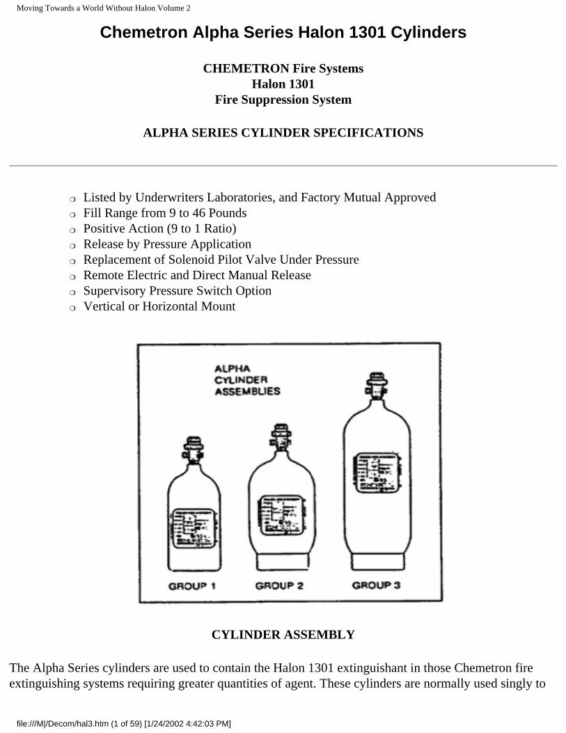
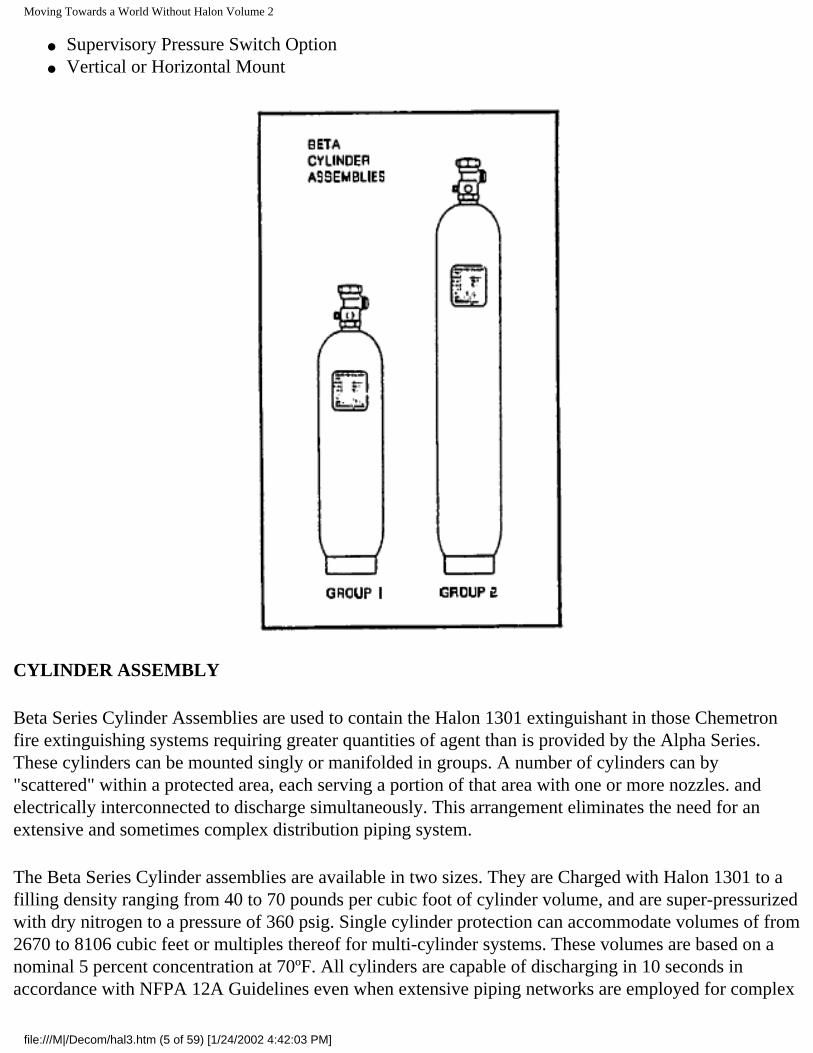
CYLINDER ASSEMBLY
The Alpha Series cylinders are used to contain the Halon 1301 extinguishant in those Chemetron fire extinguishing systems requiring greater quantities of agent. These cylinders are normally used singly to
file:///M|/Decom/hal3.htm (1 of 59) [1/24/2002 4:42:03 PM]
Moving Towards a World Without Halon Volume 2
protect a given volume. However, a number of cylinders can be "scattered" within a protected area, each serving a portion of that area with one or more nozzles, and electrically interconnected to discharge simultaneously. This arrangement eliminates the need for an extensive and sometimes complex distribution piping system.
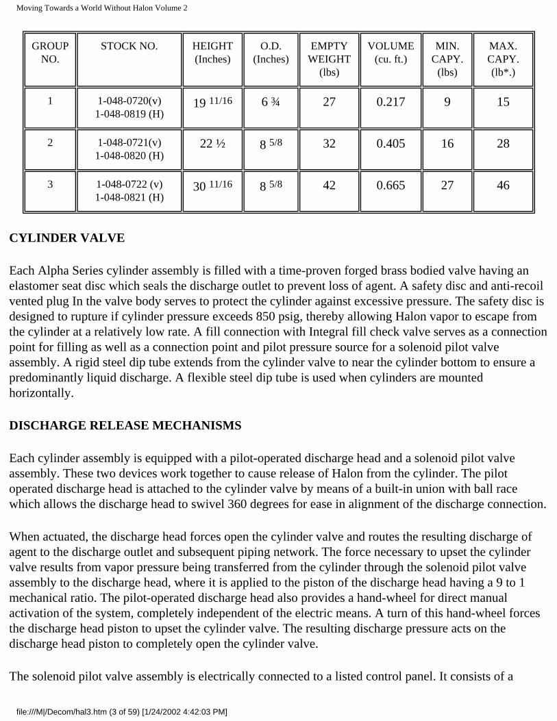
The Alpha Series cylinder assemblies are available in three sizes. They are charged with Halon 1301 to a filling density ranging from 40 to 70 pounds per cubic foot or cylinder volume. and are super-pressurized with dry nitrogen to a pressure or 360 psig. Single cylinder protection can accommodate volumes of from 437 to 2,233 cubic feet. Based on a nominal 5 percent concentration at 70° F. All cylinders are capable of discharging in 10 seconds in accordance with NFPA 12A Guidelines. Refer to the chart for cylinder capacities, dimensions and weights, Page 2.
Alpha Series Cylinder Assemblies are manufactured of special carbon steel in strict accordance with the requirements of the Department of Transportation (D.O.T.). Cylinders are hydrostatically tested for design pressure and leaks, and are coated with durable red enamel paint.
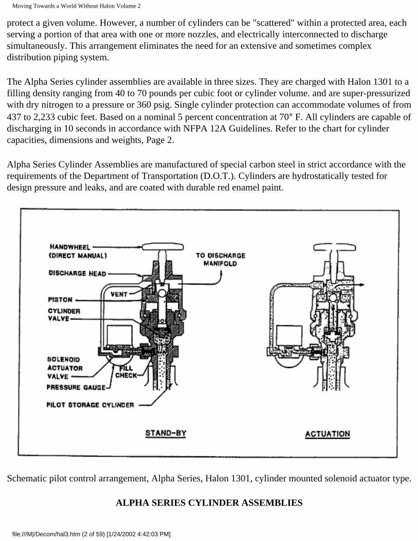
Schematic pilot control arrangement, Alpha Series, Halon 1301, cylinder mounted solenoid actuator type.
ALPHA SERIES CYLINDER ASSEMBLIES
file:///M|/Decom/hal3.htm (2 of 59) [1/24/2002 4:42:03 PM]
Moving Towards a World Without Halon Volume 2
GROUP NO.
STOCK NO. HEIGHT (Inches)
O.D. (Inches)
EMPTY WEIGHT
(lbs)
VOLUME (cu. ft.)
MIN. CAPY.
(lbs)
MAX. CAPY. (lb*.)
1 1-048-0720(v)1-048-0819 (H)
19 11/16 6 ¾ 27 0.217 9 15
2 1-048-0721(v) 1-048-0820 (H)
22 ½ 8 5/8 32 0.405 16 28
3 1-048-0722 (v)1-048-0821 (H)
30 11/16 8 5/8 42 0.665 27 46
CYLINDER VALVE
Each Alpha Series cylinder assembly is filled with a time-proven forged brass bodied valve having an elastomer seat disc which seals the discharge outlet to prevent loss of agent. A safety disc and anti-recoil vented plug In the valve body serves to protect the cylinder against excessive pressure. The safety disc is designed to rupture if cylinder pressure exceeds 850 psig, thereby allowing Halon vapor to escape from the cylinder at a relatively low rate. A fill connection with Integral fill check valve serves as a connection point for filling as well as a connection point and pilot pressure source for a solenoid pilot valve assembly. A rigid steel dip tube extends from the cylinder valve to near the cylinder bottom to ensure a predominantly liquid discharge. A flexible steel dip tube is used when cylinders are mounted horizontally.
DISCHARGE RELEASE MECHANISMS
Each cylinder assembly is equipped with a pilot-operated discharge head and a solenoid pilot valve assembly. These two devices work together to cause release of Halon from the cylinder. The pilot operated discharge head is attached to the cylinder valve by means of a built-in union with ball race which allows the discharge head to swivel 360 degrees for ease in alignment of the discharge connection.
When actuated, the discharge head forces open the cylinder valve and routes the resulting discharge of agent to the discharge outlet and subsequent piping network. The force necessary to upset the cylinder valve results from vapor pressure being transferred from the cylinder through the solenoid pilot valve assembly to the discharge head, where it is applied to the piston of the discharge head having a 9 to 1 mechanical ratio. The pilot-operated discharge head also provides a hand-wheel for direct manual activation of the system, completely independent of the electric means. A turn of this hand-wheel forces the discharge head piston to upset the cylinder valve. The resulting discharge pressure acts on the discharge head piston to completely open the cylinder valve.
The solenoid pilot valve assembly is electrically connected to a listed control panel. It consists of a
file:///M|/Decom/hal3.htm (3 of 59) [1/24/2002 4:42:03 PM]
Moving Towards a World Without Halon Volume 2
solenoid valve, pressure gauge and adapter with swivel nut and "O" ring to secure the assembly to the fill connection of the cylinder valve. The adapter is designed with a pin which upsets the internal fill check valve when the swivel nut is almost tight. The "O" ring seals the filling to prevent loss of agent This feature makes it possible to remove or install the solenoid pilot valve assembly while the cylinder is pressurized. When the assembly is in place, the normally closed seat of the solenoid valve and the pressure gauge are both exposed to cylinder pressure. The pressure gauge provides continuous visual Indication of cylinder pressure. The solenoid valve has a 1/2-inch NPT female hub with two 24-inch long wire leads for electrical connection.
A pressure switch can be supplied as an optional feature to continuously monitor the cylinder pressure, and to transmit an alarm signal in the event pressure falls below an acceptable level. A Teflon-lined braided stainless steel flexible connector is used to connect the solenoid pilot valve outlet to the pilot connection of the pilot-operated discharge head. Alpha Series cylinders are shipped with a plastic cap on the cylinder valve to protect the threads from damage during shipment.
INSTALLATION
As installed in a system, an Alpha Series cylinder assembly is mounted in a rack with a steel strap or straps to secure the cylinder. The cylinder can be mounted vertically on a wall or other stationary support with its base on the floor; or it can be elevated above the floor, using the proper rack which supports the cylinder. The cylinder assembly can also be equipped for horizontal mounting where headroom does not permit vertical mounting, such as beneath a raised computer room floor or above a suspended ceiling, etc. Electrical connection to the solenoid valve is to be made with a length of 3/8-inch flexible metallic conduit to facilitate cylinder removal for weighing, etc. A 1/2-inch braided stainless steel flexible connector with 1/2-inch NPT connections used to connect the discharge outlet of the discharge head to the system piping.
CHEMETRON BETA SERIESHALON 1301 CYLINDERS
CHEMETRON Fire SystemsHalon-1301 Fire Suppression System
BETA SERIES CYLINDER SPECIFICATIONS
● Listed by Underwriters Laboratories, and Factory Mutual Approved ● Fill Range 55 to 167 pounds ● Positive Action ● Release by Pressure Application ● Easy Removal of Actuation Devices for Maintenance or Repair Under Pressure ● Electric and Manual Release
file:///M|/Decom/hal3.htm (4 of 59) [1/24/2002 4:42:03 PM]
Moving Towards a World Without Halon Volume 2
● Supervisory Pressure Switch Option ● Vertical or Horizontal Mount
CYLINDER ASSEMBLY
Beta Series Cylinder Assemblies are used to contain the Halon 1301 extinguishant in those Chemetron fire extinguishing systems requiring greater quantities of agent than is provided by the Alpha Series. These cylinders can be mounted singly or manifolded in groups. A number of cylinders can by "scattered" within a protected area, each serving a portion of that area with one or more nozzles. and electrically interconnected to discharge simultaneously. This arrangement eliminates the need for an extensive and sometimes complex distribution piping system.
The Beta Series Cylinder assemblies are available in two sizes. They are Charged with Halon 1301 to a filling density ranging from 40 to 70 pounds per cubic foot of cylinder volume, and are super-pressurized with dry nitrogen to a pressure of 360 psig. Single cylinder protection can accommodate volumes of from 2670 to 8106 cubic feet or multiples thereof for multi-cylinder systems. These volumes are based on a nominal 5 percent concentration at 70ºF. All cylinders are capable of discharging in 10 seconds in accordance with NFPA 12A Guidelines even when extensive piping networks are employed for complex
file:///M|/Decom/hal3.htm (5 of 59) [1/24/2002 4:42:03 PM]
Moving Towards a World Without Halon Volume 2
hazards.
The basic Beta Series cylinders are manufactured of special carbon steel in strict accordance with the requirements of the Department of Transportation (D.O.T.). The cylinders are hydrostatically tested for design pressure and leaks, and are coated with durable red enamel paint.
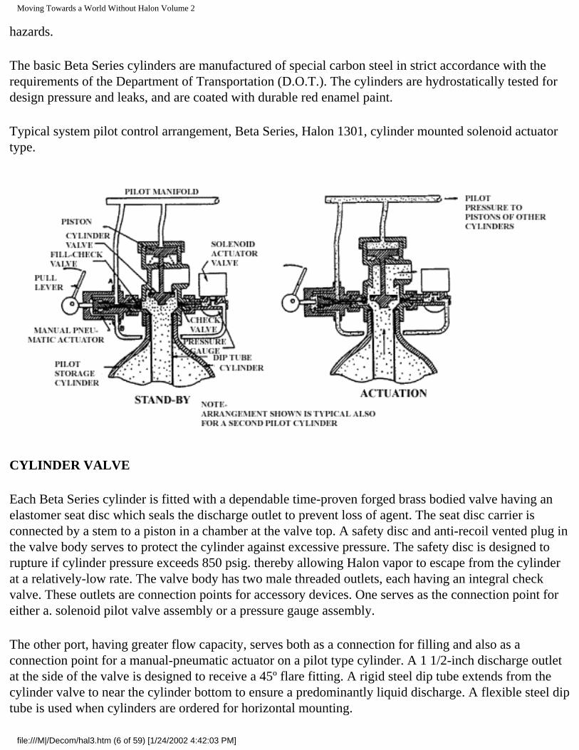
Typical system pilot control arrangement, Beta Series, Halon 1301, cylinder mounted solenoid actuator type.
CYLINDER VALVE
Each Beta Series cylinder is fitted with a dependable time-proven forged brass bodied valve having an elastomer seat disc which seals the discharge outlet to prevent loss of agent. The seat disc carrier is connected by a stem to a piston in a chamber at the valve top. A safety disc and anti-recoil vented plug in the valve body serves to protect the cylinder against excessive pressure. The safety disc is designed to rupture if cylinder pressure exceeds 850 psig. thereby allowing Halon vapor to escape from the cylinder at a relatively-low rate. The valve body has two male threaded outlets, each having an integral check valve. These outlets are connection points for accessory devices. One serves as the connection point for either a. solenoid pilot valve assembly or a pressure gauge assembly.
The other port, having greater flow capacity, serves both as a connection for filling and also as a connection point for a manual-pneumatic actuator on a pilot type cylinder. A 1 1/2-inch discharge outlet at the side of the valve is designed to receive a 45º flare fitting. A rigid steel dip tube extends from the cylinder valve to near the cylinder bottom to ensure a predominantly liquid discharge. A flexible steel dip tube is used when cylinders are ordered for horizontal mounting.
file:///M|/Decom/hal3.htm (6 of 59) [1/24/2002 4:42:03 PM]
Moving Towards a World Without Halon Volume 2
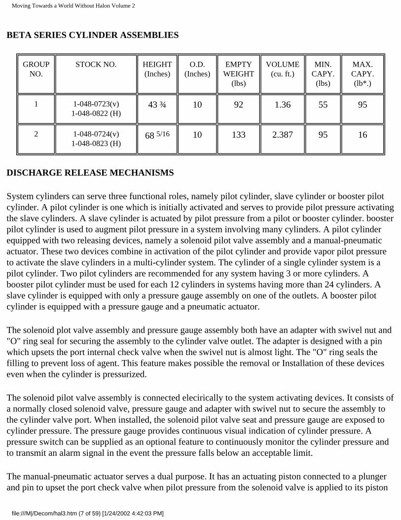
BETA SERIES CYLINDER ASSEMBLIES
GROUP NO.
STOCK NO. HEIGHT (Inches)
O.D. (Inches)
EMPTY WEIGHT
(lbs)
VOLUME (cu. ft.)
MIN. CAPY.
(lbs)
MAX. CAPY. (lb*.)
1 1-048-0723(v)1-048-0822 (H)
43 ¾ 10 92 1.36 55 95
2 1-048-0724(v) 1-048-0823 (H)
68 5/16 10 133 2.387 95 16
DISCHARGE RELEASE MECHANISMS
System cylinders can serve three functional roles, namely pilot cylinder, slave cylinder or booster pilot cylinder. A pilot cylinder is one which is initially activated and serves to provide pilot pressure activating the slave cylinders. A slave cylinder is actuated by pilot pressure from a pilot or booster cylinder. booster pilot cylinder is used to augment pilot pressure in a system involving many cylinders. A pilot cylinder equipped with two releasing devices, namely a solenoid pilot valve assembly and a manual-pneumatic actuator. These two devices combine in activation of the pilot cylinder and provide vapor pilot pressure to activate the slave cylinders in a multi-cylinder system. The cylinder of a single cylinder system is a pilot cylinder. Two pilot cylinders are recommended for any system having 3 or more cylinders. A booster pilot cylinder must be used for each 12 cylinders in systems having more than 24 cylinders. A slave cylinder is equipped with only a pressure gauge assembly on one of the outlets. A booster pilot cylinder is equipped with a pressure gauge and a pneumatic actuator.
The solenoid plot valve assembly and pressure gauge assembly both have an adapter with swivel nut and "O" ring seal for securing the assembly to the cylinder valve outlet. The adapter is designed with a pin which upsets the port internal check valve when the swivel nut is almost light. The "O" ring seals the filling to prevent loss of agent. This feature makes possible the removal or Installation of these devices even when the cylinder is pressurized.
The solenoid pilot valve assembly is connected elecirically to the system activating devices. It consists of a normally closed solenoid valve, pressure gauge and adapter with swivel nut to secure the assembly to the cylinder valve port. When installed, the solenoid pilot valve seat and pressure gauge are exposed to cylinder pressure. The pressure gauge provides continuous visual indication of cylinder pressure. A pressure switch can be supplied as an optional feature to continuously monitor the cylinder pressure and to transmit an alarm signal in the event the pressure falls below an acceptable limit.
The manual-pneumatic actuator serves a dual purpose. It has an actuating piston connected to a plunger and pin to upset the port check valve when pilot pressure from the solenoid valve is applied to its piston
file:///M|/Decom/hal3.htm (7 of 59) [1/24/2002 4:42:03 PM]
Moving Towards a World Without Halon Volume 2
at the time of system activation. With the check open, cylinder pressure is available to pilot all cylinders. It is also applied to the actuator piston in order to maintain the operated position until cylinder content is depleted. In the case of a single cylinder system, pilot pressure from the upset check valve is applied directly to a pilot port in the valve cap. In the case of a multi-cylinder system, this pilot pressure is applied to a pilot manifold. and from there to the cylinder valve cap connection ports of the pilot cylinder and all other cylinders. The pilot pressure thereby applied to the cylinder valve piston causes it to move to open the cylinder valve, resulting in a discharge of cylinder content. After the discharge is complete, a spring beneath the piston exerts a reverse force on the piston, thereby causing it to move to close the cylinder valve. The manual pneumatic actuator is equipped with a lever-operated cam, held in the non-operated position by "pull pin" and sealed with a break-seal. This feature provides an overriding direct manual means of activating the system if for some reason electric activation is not available. Operation of the lever causes cam rotation which in turn forces the actuator piston to move to upset the related check valve and activate the system in the same way as described for electric actuation.
CONNECTION
All pilot interconnections between piloting devices and cylinder valves are accomplished with Teflon-lined braided stainless steel flexible connectors. Discharge connection to the cylinder manifold or system piping is by means of a 1½-inch formed rigid steel tube with a 45º flare nut at each end. In the case of a group of cylinders connected to a discharge manifold, the connection is made with a special check valve assembly which includes a means of adjustment to accommodate minor variations in cylinder height. The check valve is used on multi-cylinder systems in accordance with NFPA 12A, and prevents back flow and resulting loss of agent from the manifold in the event of system activation when a cylinder is disconnected for weighing or servicing. A bleeder valve in the pilot manifold is normally open to atmosphere in order to prevent accumulated leakage from a solenoid valve or check valve to cause false system activation. Pilot pressure applied rapidly at the time of normal system activation causes this valve to close in order to conserve pilot pressure.
INSTALLATION
Beta Series cylinder assemblies are shipped with a plastic cap on the discharge outlet to protect the threads and flare mating surface from damage.
As installed in a system, whether. single or in groups, the Beta Series cylinders are normally positioned vertically and are secured against a wall with a stainless steel strap. The Beta Series cylinders can be equipped with special dip tubes to permit horizontal mounting where headroom does not permit vertical position such as beneath a raised floor of a computer room or above a suspended ceiling, etc.
A rack for a single cylinder is designed for attachment to a wall or other stationary vertical means of support. Rack, for multiple cylinder systems are designed to accommodate up to six cylinders on one side of a wall-attached rack of six cylinders on each side of a rack in a free-standing position. Multiple rack with cylinder discharge manifolds interconnected are used to accommodate larger numbers of cylinders.
file:///M|/Decom/hal3.htm (8 of 59) [1/24/2002 4:42:03 PM]
Moving Towards a World Without Halon Volume 2
The multi cylinder racks include provision to support of discharge manifold and pilot manifold. Discharge manifolds with welded inlet female hubs, properly spaced to correspond to the rack cylinder spacing, are available in arrangements for two through six cylinders.
Electrical connection to the solenoid valve is to be made with a length of 3/8 inch flexible metallic conduit to facilitate cylinder removal for weighing. etc.
CHEMETRON GAMMA SERIES HALON 1301 CYLINDERS
CHEMETRON Fire SystemsHalon 1301
Fire Suppression System
GAMMA SERIES CYLINDER SPECIFICATIONS
● Listed by Underwriters Laboratories, and Factory Mutual Approved ● Fill Range from 153 to 550 Pounds ● Pressure Differential Valve ● Positive Action ● Actuator and Gauge Replacement Under Pressure ● Electric and Manual Release ● Supervisory Pressure Switch Option ● Liquid Level Locator Option
file:///M|/Decom/hal3.htm (9 of 59) [1/24/2002 4:42:03 PM]
Moving Towards a World Without Halon Volume 2
CYLINDER ASSEMBLY
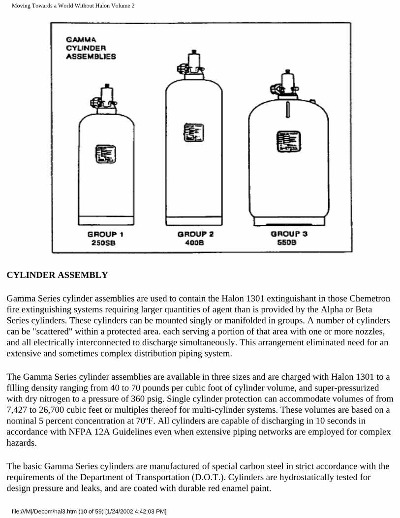
Gamma Series cylinder assemblies are used to contain the Halon 1301 extinguishant in those Chemetron fire extinguishing systems requiring larger quantities of agent than is provided by the Alpha or Beta Series cylinders. These cylinders can be mounted singly or manifolded in groups. A number of cylinders can be "scattered" within a protected area. each serving a portion of that area with one or more nozzles, and all electrically interconnected to discharge simultaneously. This arrangement eliminated need for an extensive and sometimes complex distribution piping system.
The Gamma Series cylinder assemblies are available in three sizes and are charged with Halon 1301 to a filling density ranging from 40 to 70 pounds per cubic foot of cylinder volume, and super-pressurized with dry nitrogen to a pressure of 360 psig. Single cylinder protection can accommodate volumes of from 7,427 to 26,700 cubic feet or multiples thereof for multi-cylinder systems. These volumes are based on a nominal 5 percent concentration at 70ºF. All cylinders are capable of discharging in 10 seconds in accordance with NFPA 12A Guidelines even when extensive piping networks are employed for complex hazards.
The basic Gamma Series cylinders are manufactured of special carbon steel in strict accordance with the requirements of the Department of Transportation (D.O.T.). Cylinders are hydrostatically tested for design pressure and leaks, and are coated with durable red enamel paint.
file:///M|/Decom/hal3.htm (10 of 59) [1/24/2002 4:42:03 PM]
Moving Towards a World Without Halon Volume 2
CYLINDER ASSEMBLY
Gamma Series cylinder assemblies are used to contain the Halon 1301 extinguishant in those Chemetron fire extinguishing systems requiring larger quantities of agent then is provided by the Alpha or Beta Series cylinders. These cylinders can be mounted
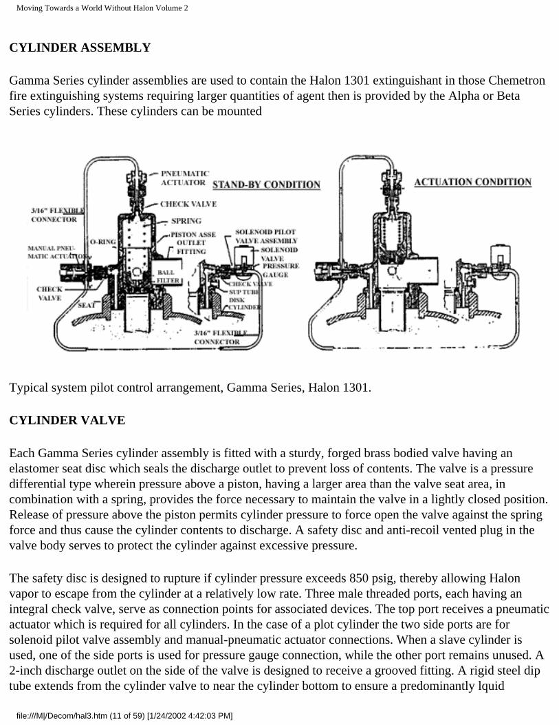
Typical system pilot control arrangement, Gamma Series, Halon 1301.
CYLINDER VALVE
Each Gamma Series cylinder assembly is fitted with a sturdy, forged brass bodied valve having an elastomer seat disc which seals the discharge outlet to prevent loss of contents. The valve is a pressure differential type wherein pressure above a piston, having a larger area than the valve seat area, in combination with a spring, provides the force necessary to maintain the valve in a lightly closed position. Release of pressure above the piston permits cylinder pressure to force open the valve against the spring force and thus cause the cylinder contents to discharge. A safety disc and anti-recoil vented plug in the valve body serves to protect the cylinder against excessive pressure.
The safety disc is designed to rupture if cylinder pressure exceeds 850 psig, thereby allowing Halon vapor to escape from the cylinder at a relatively low rate. Three male threaded ports, each having an integral check valve, serve as connection points for associated devices. The top port receives a pneumatic actuator which is required for all cylinders. In the case of a plot cylinder the two side ports are for solenoid pilot valve assembly and manual-pneumatic actuator connections. When a slave cylinder is used, one of the side ports is used for pressure gauge connection, while the other port remains unused. A 2-inch discharge outlet on the side of the valve is designed to receive a grooved fitting. A rigid steel dip tube extends from the cylinder valve to near the cylinder bottom to ensure a predominantly lquid
file:///M|/Decom/hal3.htm (11 of 59) [1/24/2002 4:42:03 PM]
Moving Towards a World Without Halon Volume 2
discharge.
DISCHARGE RELEASE MECHANISMS
In a system, there can be two functional types of cylinder assemblies, namely pilot cylinder and slave cylinder. A pilot cylinder is one which is initially activated and serves to provide pilot pressure for activating the slave cylinder or cylinders. A slave cylinder is one which is piloted into action by the plot cylinder.
A pilot cylinder is equipped with two releasing devices, namely a solenoid pilot valve assembly and a manual-pneumatic actuator. These two devices work together to activate the pilot cylinder and provide pilot pressure to activate the slave cylinder valves in a multi-cylinder system. A slave cylinder is equipped only with a pressure gauge assembly.
The solenoid plot valve assembly and pressure gauge assembly both have an adapter with swivel nut and "O" ring for securing the assembly to the cylinder valve port. The adapter is designed with a pin which upsets the internal check valve when the swivel nut is almost light. The "O" ring is used to seal the fitting and prevent loss of agent. This feature makes possible for removal or installation of these devices when the cylinder is pressurized.
The solenoid plot valve assembly is electrically connected to a listed fire suppress control panel. It consists of a solenoid valve pressure gauge and adapter with swivel: and "O" ring seal. When the assembly applied to the valve port, a pin upsets check valve to apply pressure to the normally closed solenoid valve and to the pressure gauge. The pressure gauge provides continuous visual indication of cylinder pressure.
A pressure switch can be supplied as optional feature to continuously monitor cylinder pressure, and to transmit an alarm signal in the event the pressure falls be an acceptable limit.
The manual-pneumatic actuator serve dual role. It has an actuating piston connected to a plunger and pin to upset the check valve when pilot pressure from solenoid pilot valve is applied to its piston the time of system activation. Connection the valve port is made by the same swivel nut and "O" ring seat as previously described except that its pin does not upset the check valve until the actuator is activated pneumatically or manually.
The manual-pneumatic actuator is equipped with a lever-operated cam, held in the non-operated position by a "pull pin" and sealed with a break-seal. This feature provides an overriding direct manual means of activating the system in the event the electric release circuit is not available. Operation of the lever causes cam rotation which in turn forces the actuator piston to move to upset the related check valve and to activate the system in the same way as described for electric activation.
The pneumatic actuator accomplishes the final step in activating the cylinder valve to obtain a discharge.
file:///M|/Decom/hal3.htm (12 of 59) [1/24/2002 4:42:03 PM]
Moving Towards a World Without Halon Volume 2
It attaches to the cylinder valve top port by means of a swivel nut with an "O" ring seal. It contains a piston and plunger. Pilot pressure from the manual-pneumatic actuator acting on the piston forces the port check valve to open to relieve pressure from above the cylinder valve piston. This enables cylinder pressure to force the piston open, resulting in a discharge of cylinder content.
CONNECTIONS
All pilot interconnections between components of the pilot cylinder and between cylinders are accomplished with rugged Teflon-lined braided stainless steel flexible connectors.
Connection to the discharge manifold or piping is made by means of grooved fittings and piping. In the case of cylinder groups with a discharge manifold, a check valve must be provided in the connection from each cylinder in accordance with NFPA 12A. This prevents loss of agent from the manifold if a discharge were to occur when a cylinder had been disconnected for weighing or servicing.
INSTALLATION
Gamma Series cylinders are shipped without any associated devices attached. The discharge outlet is equipped with a 2-inch grooved filling and cap with anti-recoil plug.
As installed in a system, whether singly or in multiples, the Gamma Series cylinder assemblies are positioned vertically and are secured in a rack with a stainless steel strap The racks are normally mounted against a wall or bulkhead but can be free-standing.
Each rack is designed to accommodate up to three Gamma Series cylinder assemblies Multiple racks with the cylinder discharge manifolds interconnected are used to accommodate larger numbers of cylinders.
Discharge manifold with welded inlet female hubs, properly spaced to correspond to the rack cylinder spacing, are available in arrangements for two and three cylinders.
Electrical connection to the solenoid valve is to be made with a length of 3/8-inch flexible metallic conduit to facilitate cylinder removal for weighing etc.
file:///M|/Decom/hal3.htm (13 of 59) [1/24/2002 4:42:03 PM]

Moving Towards a World Without Halon Volume 2
CHEMETRON HIGH FLOW-600HALON 1301 SYSTEMS
SECTION IA - GENERAL DESCRIPTION
HIGH FLOW-600 HALON 1301 SYSTEMS
GENERAL
Each Fire Systems halon 1301 system is specifically engineered to accommodate the individual demands of the areas to be protected. The wide range and design of available components provides the flexibility necessary for this custom design. The use of multiple storage cylinders and selector valves enables a single group of cylinders to serve more than one protected area on an individual basis.
file:///M|/Decom/hal3.htm (14 of 59) [1/24/2002 4:42:03 PM]
Moving Towards a World Without Halon Volume 2
Fire Systems offers three series of storage components, namely the High Flow Series 360 and 600 and Series 70. Although the basic function is the same in each series, the components and their arrangements differ somewhat. This section covers the High Flow Series - 600.
The High Flow system permits higher discharge rates and is particularly adaptable to areas involving larger quantities of halon 1301 or short discharge duration.
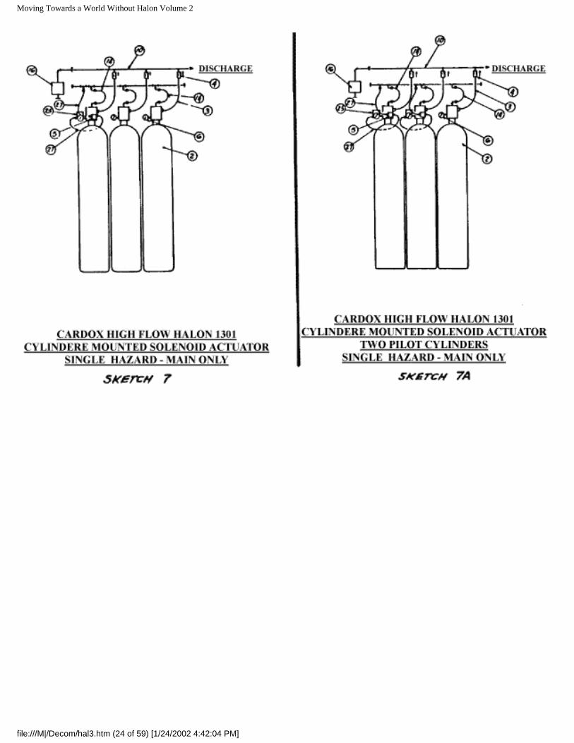
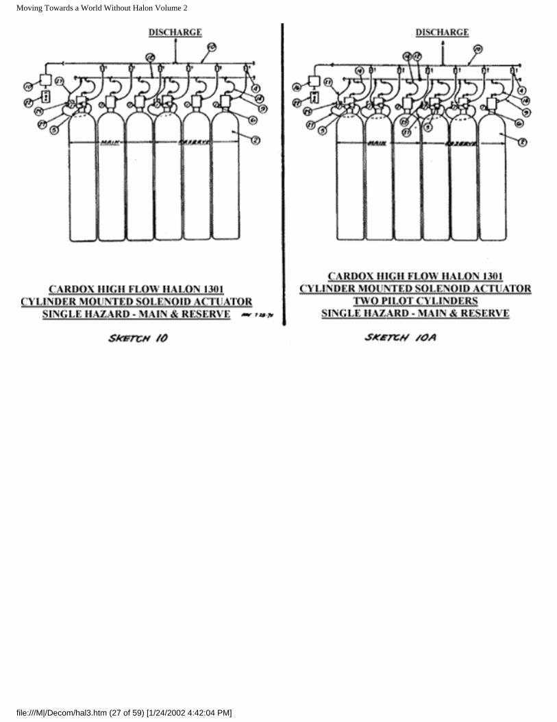
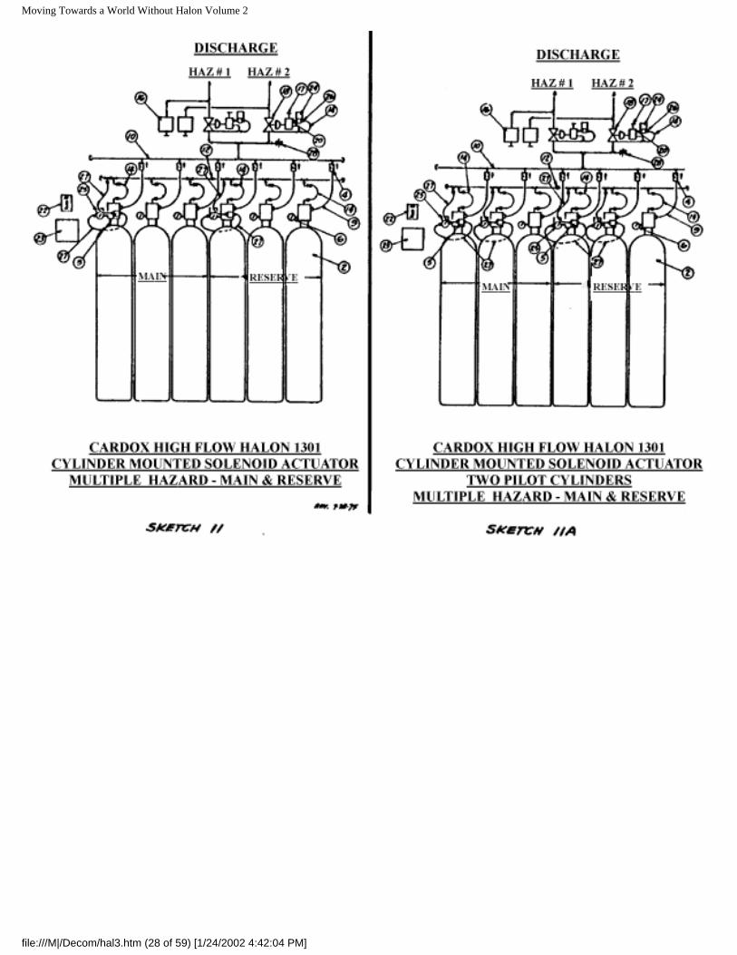
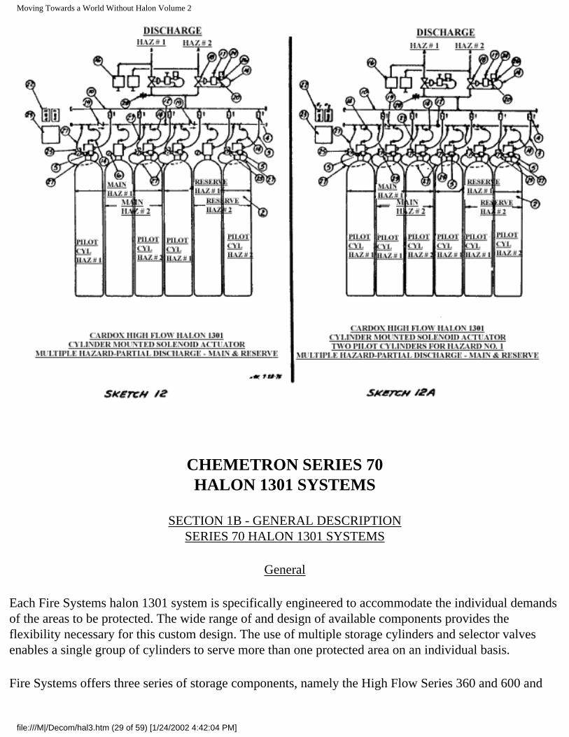
Sketches 7 and 10 illustrate typical system arrangements for a single protected area, with and without a connected reserve cylinder bank. These basic schemes can be readily modified to serve more than one area by the addition of selector valves and the necessary related control devices as illustrated on Sketches 8 and 11. They can be further modified by the proper treatment of cylinder piloting and manifolding to actuate the required number of cylinders (partial discharge) of a bank to satisfy the varying agent requirements for each of the protected areas as illustrated on Sketches 9 and 12.
Two pilot cylinders must be used for systems having in excess of 12 cylinders. A booster pilot cylinder must be included for each 12 cylinders in systems employing in excess of 24 cylinders. (A booster pilot cylinder is the same as a normal pilot cylinder except that the solenoid pilot valve is eliminated.) The 3/16 in. flexible connector from the "B" port of the manual-pneumatic actuator is eliminated and "B" port is capped using a flare cap. See Plate H-37F. Generally, the booster pilot cylinder is located adjacent to the normal pilot cylinders although there may be cases where the booster pilot is located differently due to unusual cylinder bank arrangement.
The systems illustrated in Sketches 7A through 12A are the same as that for Sketches 7 through 12 except that two pilot cylinders are used where 3 or more cylinders are involved in a discharge. This alternate is recommended to provide redundancy of controls.
Although the sketches show selector valves for only two protected areas, the number can be increased within practical limits. A description of the various components is covered in the following paragraphs:
Cylinder Assembly (Plate H-26C):
Halon 1301 is stored in specially designed cylinder assemblies. These are available in a number of capacities and are charged with halon 1301 to a filling-density up to 70 pounds per cubic foot of cylinder volume. The cylinders are super-pressurized with dry nitrogen to a pressure of 600 psig ( +5%) at 70ºF. Each cylinder is equipped with an identification band indicating the quantity of halon.
The cylinder assembly is composed of a cylinder, a dip tube and a cylinder valve.
Cylinder: The steel cylinders are manufactured to the requirements of the D.O.T. for compressed gas and have external neck threads for cylinder valve connection.
file:///M|/Decom/hal3.htm (15 of 59) [1/24/2002 4:42:03 PM]
Moving Towards a World Without Halon Volume 2
Dip Tube: A flanged dip tube extends from the cylinder neck down to the bottom of the cylinder. The flange, clamped between the top of the cylinder neck and the cylinder valve, supports the dip tube.
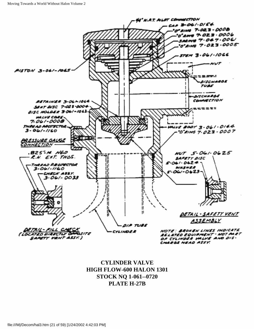
Cylinder Valve: (Plate H-27B) A pressure operated cylinder valve having a forged brass body and cap is attached to the cylinder neck and serves to control the flow of halon from the cylinder. A neoprene seat disc and disc carrier are connected by a stem to an operating piston at the top. The piston to valve ratio is approximately 3 to 1.
The cylinder valve has five connections as follows:
Fill Check Connection: A fill check connection housing a fill check valve serves for cylinder filling operations and also for attachment of a manual-pneumatic actuator on those cylinders used for piloting other cylinders.
Pressure Gauge Connection: A gauge connection housing a small check valve serves as attachment point for the cylinder pressure gauge or solenoid pilot actuator in the pilot cylinder for cylinder mounted actuator type system.
Safety Disc Connection: A frangible safety disc is connected to the valve body and serves as a pressure relief device to protect the cylinder against excessive internal pressure. Its disc rupture point is in the range of 2700 to 2800 psi.
Discharge Connection: A 1-1/2 in O.D. flare connection serves as the discharge port.
Pilot Connection: A 1/4 in. NPT tap in the cylinder valve cap provides a means of applying pilot pressure above the operating piston.
Discharge Tube Assembly (Plate H-31 C):
A formed 1-1/2 in. O.D. steel tube assembly with flare nut at each end is used to connect the cylinder valve to the check valve assembly and in turn to the discharge manifold.
Check Valve Assembly (Plate H-55E):
A check valve assembly is used to connect the discharge tube to the discharge manifold. This is a dual purpose assembly. The check valve prevents back flow from the manifold in the event that the system is discharged when one or more cylinders are disconnected such as for weighing or general servicing. Further, the assembly is designed to provide height adjustment 3/8 in. above or below a nominal height to accommodate minor differences in cylinder height or floor unevenness.
Pressure Gauge Assembly (Plate H-28):
file:///M|/Decom/hal3.htm (16 of 59) [1/24/2002 4:42:03 PM]
Moving Towards a World Without Halon Volume 2
A pressure gauge assembly is provided for each cylinder to provide a means of visual surveillance of the pressure condition within the cylinder. The assembly contains a swivel nut and "O" ring seal for attachment to the gauge connection of the cylinder valve. A pin in the assembly upsets the gauge check valve when the swivel nut is almost tight at which time the "O" ring seal prevents agent loss. The pressure gauge can be removed for replacement of checking without loss of agent since the gauge check valve closes as the gauge assembly is removed.
Manual-Pneumatic Actuator (Plate H-47B):
This device attaches to the fill check connection of one or more of the cylinders of a cylinder group which are called pilot cylinders. This is a dual purpose device having an actuating piston connected to a pin to upset the fill check valve when pilot pressure is applied to the piston. With the fill check open, cylinder pressure is applied through the pilot connection to the operating piston of the cylinder valve, thereby opening the cylinder to discharge its contents.
A manual lever and cam arrangements on the actuator permits actuation of the device on a manual basis, thereby overriding and independent of electric power or pilot pressure. A pull-pin and seal prevents accidental operation of the manual lever.
A swivel nut and "O" ring seal on the device provides for attachment and seal at the connection point.
Piloting Device
The system utilizes a Solenoid Pilot Actuator to provide pilot pressure for actuation whether system actuation is by automatic (detection device) or manual-electric (pushbutton) means.
The Solenoid Pilot Actuator (Plate H-47C) includes a pressure gauge and adapter with swivel nut and "O" ring seal which is attached to the pressure gauge connection of the cylinder valve. The adapter upsets the check valve when the swivel nut is almost tight at which time the "O" ring seal prevents agent loss. With the check valve open, pilot cylinder pressure is applied to the normally closed solenoid valve and the pressure gauge. The pressure gauge provides for visual surveillance of the pressure condition within the cylinder. Actuation of the solenoid pilot valve permits pressure to be applied through a hose connector to the manual-pneumatic actuator which in turn applies cylinder pressure to its operating piston and the operating pistons of any other cylinders to-be discharged.
The solenoid pilot valve assembly can be removed for servicing or testing without loss of agent since the check valve will close as the assembly is removed.
A flexible electrical conduit is required for connection to the solenoid pilot valve assembly to the system conduit. The flexibility facilitates removal of the assembly as well as the cylinder for servicing.
file:///M|/Decom/hal3.htm (17 of 59) [1/24/2002 4:42:03 PM]
Moving Towards a World Without Halon Volume 2
Flexible Pilot Hose:
Lengths of 3/16 in. flexible pilot hose are used to interconnect the cylinder valve devices and for connections to the pilot manifolds. These hoses have a stainless steel wire braid cover and a teflon liner and are fitted at each end with a 1/4 in. swivel flare nut.
Selector Valve (Plates H-54, H-54A and H-54E):
Systems protecting more than one area on an individual basis require selector valves to direct the discharged halon 1301 into the desired area. The selector valves are available in various sizes from 1/2 in. through 6 in. The sizes up through 2 in. have cast bronze bodies and caps. The larger sizes are cast steel. All are pressure operated, having a seat disc and disc carrier connected by a stem to a piston. Application of pilot pressure from an associated pilot control valve to the selector valve piston causes the selector valve to open and remain open until pilot pressure is exhausted.
Pilot Control Valve (Plate H-53B):
A pilot control valve is used to provide the pilot pressure for each selector valve. The pilot valve has a forged brass body with brass and stainless trim parts. The valve is pressure operated having a two part piston connected by a stem to a disc carrier and seat disc. The two part piston serves to lock the valve in the open position until pressure within the valve is depleted when the cylinders have emptied. Pressure for piloting the pilot control valve is supplied either from the control cylinder or from the discharge manifold depending on the particular system arrangement. It is applied to the chamber above the pilot control valve piston by means of a two way solenoid valve and filter. Pilot pressure for actuating the selector valve is supplied from the discharge manifold through the pilot control valve.
Shuttle Valve (Plate H-38):
Shuttle valves (double check valves) are used in some pilot line arrangements to isolate sections of the pilot lines when certain sections are common to several areas. The shuttle valve is in effect a tee which permits two inlet lines to converge into a common side outlet. Pressure at one inlet moves an internal shuttle to seal off the other inlet.
Bleeder Valve (Plate H-56, No. 1-061-0731-1):
Bleeder valves are used in pilot lines to prevent accumulation of pressure due to accidental leakage through a device, which if unvented could cause a false discharge of the system. The valve is normally open to atmosphere and closes at approximately 50 psi when full pilot pressure is applied on normal system operation. Refer to Plate H-56.
Pressure Switch (Plates E-59. H-59A-and H-59B):
file:///M|/Decom/hal3.htm (18 of 59) [1/24/2002 4:42:03 PM]
Moving Towards a World Without Halon Volume 2
Pressure switches are used in the system to implement the shut-down of various items of equipment such as fans, power and for annunciation and alarm purposes.
Pressure Release (Plate H-58):
Pressure releases are used for closing doors, dampers, etc., on actuation of the system. They have an internal piston and an external spring clip to which is attached a cable or chain to hold the released device in the open position. The release devices are generally connected by piping to the discharge piping. Pressure from the discharge forces the piston forward in the release thereby releasing the spring clip and permitting the released device to close.
Discharge Delay Devices:
In most instances the discharge from automatic means (detection devices) is delayed for a pre-discharge warning period. This is normally accomplished electrically by including a time delay relay or a timer in the automatic actuation circuit. The electrical impulse from a detection device is delayed from reaching the solenoid pilot valve for a pre-determined period, during which an alarm is sounded to alert personnel.
Electrical Remote Manual Release (Various):
These devices are located at one or more doors to the protected area to provide a Manual means of actuating the system in the event a fire is observed by personnel prior to detection device response. Several types are available although the most common is a pushbutton station with a break-glass device to preclude accidental operation. Operation of a release energizes the solenoid pilot valve either directly or indirectly through a relay and causes system actuation.
Fire Detection Devices:
Automatic actuation of a system can be provided by using any one of a number of Underwriters' Laboratories listed or Factory Mutual approved detection devices such as ionization products of combustion devices, smoke detection devices, thermal switches, etc., depending on the nature of fires which can be predicted for an area. Sometimes more than one type are used to provide the most positive response. All involve the transmission of an electrical impulse which energizes the solenoid pilot valve either directly or through a relay and causes system actuation.
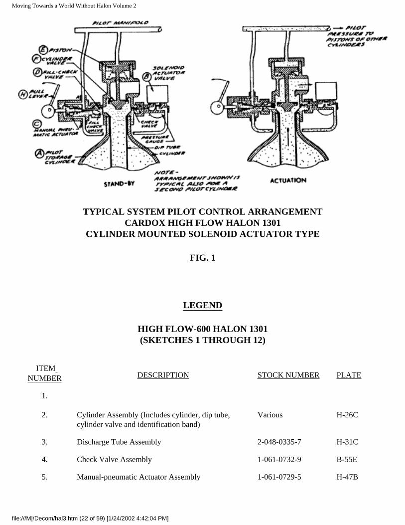
Description of System Operation
Automatic Operation:
Cylinder Mounted Solenoid Actuator Type (Figure 1): Automatic actuation is powered by vapor pressure from the pilot storage cylinder (A). Pilot pressure is applied continuously to a normally closed solenoid actuator valve (B). with pressure gauge, through its attachment to the gauge connection of the pilot
file:///M|/Decom/hal3.htm (19 of 59) [1/24/2002 4:42:03 PM]
Moving Towards a World Without Halon Volume 2
cylinder valve. The solenoid actuator is connected by a wiring circuit to the detection devices in the protected area. A signal from a detection device causes the solenoid actuator valve to open and apply pilot pressure to Port B of the pneumatic-manual actuator (C) of the pilot cylinder. Pilot pressure thus applied acts on the piston of the actuator causing it to force open the fill-check valve (D), permitting pilot cylinder vapor pressure to be applied through Port A of the actuator and interconnecting flexible hose to the pilot cylinder valve piston (E) causing the piston to move down to unseat the cylinder valve (F), permitting the cylinder contents to discharge to the cylinder manifold. Simultaneously, pilot pressure is also applied through the pilot manifold to the pistons of the cylinder valves of all other related cylinders causing them to discharge.
The cylinder valve piston has an operating ratio of 3 to 1 to insure proper function under varying pressure conditions.
Selector Valves: When selector valves are used to permit a single cylinder bank to serve more than one protected area, a pressure operated 3-way pilot valve is provided for each selector valve. Pilot pressure for operation of the selector valve is normally taken from the discharge manifold. The pilot valve is usually actuated by a solenoid valve utilizing either discharge manifold pressure or control cylinder pressure.
CHEMETRON fire extinguishing equipment …..
file:///M|/Decom/hal3.htm (20 of 59) [1/24/2002 4:42:03 PM]
Moving Towards a World Without Halon Volume 2
CYLINDER VALVEHIGH FLOW-600 HALON 1301
STOCK NQ 1-061--0720PLATE H-27B
file:///M|/Decom/hal3.htm (21 of 59) [1/24/2002 4:42:03 PM]
Moving Towards a World Without Halon Volume 2
TYPICAL SYSTEM PILOT CONTROL ARRANGEMENTCARDOX HIGH FLOW HALON 1301
CYLINDER MOUNTED SOLENOID ACTUATOR TYPE
FIG. 1
LEGEND
HIGH FLOW-600 HALON 1301(SKETCHES 1 THROUGH 12)
ITEM NUMBER DESCRIPTION STOCK NUMBER PLATE
1.
2. Cylinder Assembly (Includes cylinder, dip tube, cylinder valve and identification band)
Various H-26C
3. Discharge Tube Assembly 2-048-0335-7 H-31C
4. Check Valve Assembly 1-061-0732-9 B-55E
5. Manual-pneumatic Actuator Assembly 1-061-0729-5 H-47B
file:///M|/Decom/hal3.htm (22 of 59) [1/24/2002 4:42:04 PM]
Moving Towards a World Without Halon Volume 2
6. Pressure Gauge Assembly 2-024-0001-6 H-28A
7.
8.
9.
10. Manifold (Normally 2-1/2 in.) Various
11. Bleeder Valve - 1/4 in. 1-061-0731-1 H-56
12. Blind Adapter - 1/4 in. 3-039-0007-0
13. Cylinder Rack Kit Various Various
14. Flexible Pilot Connector - 3/16 in. x 16 in. long 1-026-0260-4 H-37B
15. Shuttle Valve 1-061-0256-9 H-38
16. Pressure Switch (4-pole, standard) 1-017-0065-6 B-59
17. Pilot Control Valve 1-061-0640-4 H-53B
18. Selector Valve Various H-54
H-54A
H-54E
19. Check Valve- 1/4 in. 7-061-0009-6 H-55F
20. Hex Nipple - Vented 3-044-0032-8 H-56A
21. Switching Valve 1-061-0595-0 E-39
22. Transfer Switch (Main-Reserve)
23. Relay Cabinet Various
24. Solenoid Valve Various H-47
25. Solenoid Pilot Valve Assembly Various B-47C
26. 1/4 in. Filter 7-086-0004-4 B-57
27. Flexible Pilot Connector - 3/16 in. x 20 in. long 1-026-0267-9
28. Relief Valve - Rupture Disc 3-071-0006-5 H-57A
file:///M|/Decom/hal3.htm (23 of 59) [1/24/2002 4:42:04 PM]
Moving Towards a World Without Halon Volume 2
file:///M|/Decom/hal3.htm (24 of 59) [1/24/2002 4:42:04 PM]
Moving Towards a World Without Halon Volume 2
file:///M|/Decom/hal3.htm (25 of 59) [1/24/2002 4:42:04 PM]

Moving Towards a World Without Halon Volume 2
file:///M|/Decom/hal3.htm (26 of 59) [1/24/2002 4:42:04 PM]
Moving Towards a World Without Halon Volume 2
file:///M|/Decom/hal3.htm (27 of 59) [1/24/2002 4:42:04 PM]
Moving Towards a World Without Halon Volume 2
file:///M|/Decom/hal3.htm (28 of 59) [1/24/2002 4:42:04 PM]
Moving Towards a World Without Halon Volume 2
CHEMETRON SERIES 70HALON 1301 SYSTEMS
SECTION 1B - GENERAL DESCRIPTIONSERIES 70 HALON 1301 SYSTEMS
General
Each Fire Systems halon 1301 system is specifically engineered to accommodate the individual demands of the areas to be protected. The wide range of and design of available components provides the flexibility necessary for this custom design. The use of multiple storage cylinders and selector valves enables a single group of cylinders to serve more than one protected area on an individual basis.
Fire Systems offers three series of storage components, namely the High Flow Series 360 and 600 and
file:///M|/Decom/hal3.htm (29 of 59) [1/24/2002 4:42:04 PM]
Moving Towards a World Without Halon Volume 2
Series 70. This section covers Series 70. Two pilot arrangements are available. One obtains its pilot pressure directly from the pilot storage cylinder. The other utilizes a separate control cylinder to provide pilot pressure.
Series 70 System Description
The Series 70 system is generally used where smaller quantities of storage are required or where lower rates of discharge are in order such as for an extended discharge. Two pilot arrangements are available with each type. One obtains its pilot pressure directly from the pilot storage cylinder. The other utilizes a separate control cylinder to provide pilot pressure.
Cylinder Mounted Solenoid Actuator Type:
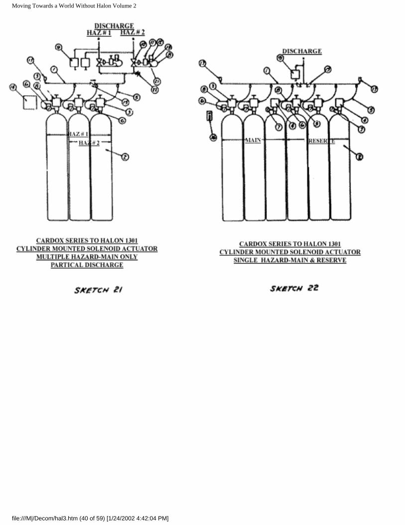
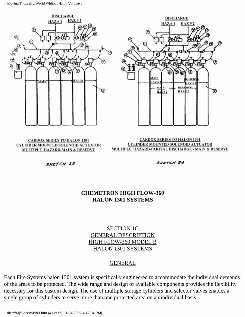
Sketches 19 and 22 illustrate typical Series 70 system arrangement of this type for a single protected area, with and without a connected reserve cylinder bank. These basic schemes can be readily modified to serve more than one area by the additional selector valves and the necessary related control devices as illustrated on Sketches 20 and 23. They can further be modified by the proper treatment of cylinder piloting and manifolding to actuate only the required number of cylinders (partial discharge) of a bank to satisfy the varying requirements for each of the protected areas as illustrated on Sketches 21 and 24.
Although the illustrations show selector valves for only two protected areas, the number can be increased within practical limits.
A description of the various components is covered in the following paragraphs.
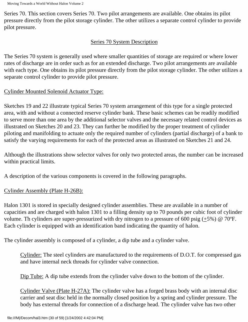
Cylinder Assembly (Plate H-26B):
Halon 1301 is stored in specially designed cylinder assemblies. These are available in a number of capacities and are charged with halon 1301 to a filling density up to 70 pounds per cubic foot of cylinder volume. Th cylinders are super-pressurized with dry nitrogen to a pressure of 600 psig (+5%) @ 70ºF. Each cylinder is equipped with an identification band indicating the quantity of halon.
The cylinder assembly is composed of a cylinder, a dip tube and a cylinder valve.
Cylinder: The steel cylinders are manufactured to the requirements of D.O.T. for compressed gas and have internal neck threads for cylinder valve connection.
Dip Tube: A dip tube extends from the cylinder valve down to the bottom of the cylinder.
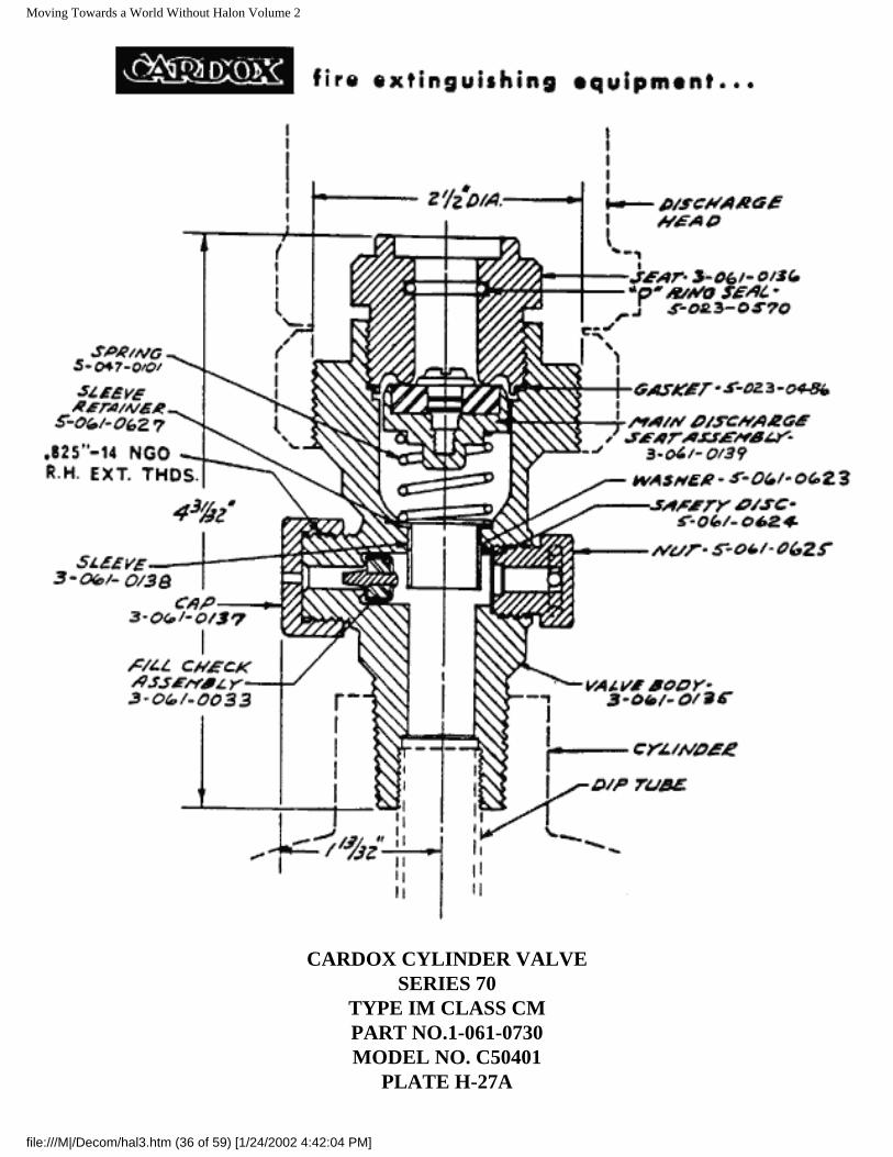
Cylinder Valve (Plate H-27A): The cylinder valve has a forged brass body with an internal disc carrier and seat disc held in the normally closed position by a spring and cylinder pressure. The body has external threads for connection of a discharge head. The cylinder valve has two other
file:///M|/Decom/hal3.htm (30 of 59) [1/24/2002 4:42:04 PM]
Moving Towards a World Without Halon Volume 2
connections as follows:
Safety Disc Connection: A frangible disc is connected to the valve body and serves as a pressure relief device to protect the cylinder against excessive internal pressure. Its disc rupture point is in the range of 2700 to 2800 psi.
Fill Check Connection: A fill check connection housing a fill check valve serves for cylinder filling operations and also for attachment of the cylinder pressure gauge and for the solenoid pilot actuator on the pilot cylinders where the actuator is cylinder mounted.
Discharge Heads:
Each cylinder is equipped with a discharge head that attaches to the cylinder by means of a swivel nut which engages the threads of the cylinder valve. Two types of discharge heads are used, namely pilot operated and pressure operated. Both types include an internal operating piston connected to a hollow stem which serves to upset the cylinder valve on actuation and also serves as an outlet for the cylinder discharge. A ball check at the top of the stem provides a safety feature to prevent back flow from the cylinder at the time of system actuation. Both heads have a 1/2 in. NPT female discharge connection.
Pilot Operated Discharge Head (Plate H-30A): This head has a 1/4 in. NPT connection for pilot pressure inlet directly to the top of the piston and is used only on pilot cylinders, since these are the ones that are actuated by pilot pressure and are discharged first. Normally the pilot operated head on pilot cylinders for an extended discharge does not have a handwheel since actuation is from the initial discharge cylinders which have the handwheel for manual actuation. The pilot operated discharge head will also operate from manifold pressure which is applied against the piston. An internal vent serves to prevent accumulation of pressure on the piston in case of leakage through the solenoid actuator valve and thus prevents accidental discharge.
Pressure Operated Discharge Head (Plate H-29A): This head is used on all but the pilot cylinders. It has the same construction as a pilot operated discharge head except that it lacks the pilot connection and the handwheel. It is operated by manifold pressure from the pilot cylinder discharge which is applied through the discharge connection to the piston.
Flexible Connector (Plate H-31A):
A 1/2 in. flexible connector is used to connect each cylinder to the cylinder manifold. These have a stainless steel wire braid cover and a teflon liner. Each end has a 1/2 in. NPT male thread.
Solenoid Pilot Actuator Assembly (Plate 47D):
The system uses a Solenoid Pilot Actuator to provide pilot pressure for actuation whether system
file:///M|/Decom/hal3.htm (31 of 59) [1/24/2002 4:42:04 PM]
Moving Towards a World Without Halon Volume 2
actuation is by automatic (detection device) or manual electric (pushbutton) means.
The Solenoid Pilot Valve Assembly including a pressure gauge and adapter with swivel nut is attached to the fill check connection of the cylinder valve. A pin in the adapter upsets the fill check valve when the swivel nut is almost tight at which time the "O" ring seal prevents agent loss. With the check valve open, pilot cylinder pressure is applied to the pressure gauge. The pressure gauge provides a means of visual surveillance of the pressure condition within the cylinder. Actuation of the solenoid pilot valve permits pressure to be applied through a pilot hose connection to the pilot operated discharge head pilot connection which in turn opens the cylinder valve resulting in discharge from the cylinder.
The solenoid pilot valve assembly can be removed for servicing or testing without loss of agent since the fill check valve will close as the assembly is removed.
A flexible electrical conduit is required for connection to the solenoid pilot valve assembly to the system conduit. The flexibility facilitates removal of the assembly as well as the cylinder.
Flexible Pilot Hose:
Lengths of 3/16 in. flexible pilot hose are used to interconnect the cylinder valve devices and for connections to the pilot manifolds. These hoses have a stainless steel wire braid cover and a teflon liner and are fitted at each end with 1/4 in. swivel flare nut.
Selector Valve (Plates_H-54, H-54A & H-54E):
Systems protecting more than one area on an individual basis require selector valves to direct the discharged halon 1301 into the desired area. The selector valves are available in various sizes from 1/2 in. to 6 in. The sizes up through 2 in. have cast bronze bodies and caps. The larger sizes are cast steel. All are pressure operated, having a seat disc and disc carrier connected by a stem to a piston. Application of pilot pressure from an associated pilot control valve to the selector valve piston causes the selector valve to open and remain open until pilot pressure is exhausted.
Pilot Control Valve (Plate H-53B):
A pilot control valve is used to provide the pilot pressure for each selector valve. The pilot valve has a brass body with brass and stainless trim parts. The valve is pressure operated having a two part piston connected by a stem to a disc carrier and seat disc. The two part piston serves to lock the valve in the open position until pressure within the valve is depleted when the cylinders have emptied. Pressure for piloting the pilot control valve is supplied either from the control cylinder or from the discharge manifold depending on the particular system arrangement. It is applied to the chamber above the pilot control valve piston by means of a two way solenoid valve and filter. Pilot pressure for actuating the selector valve is supplied from the discharge manifold through the pilot control valve.
file:///M|/Decom/hal3.htm (32 of 59) [1/24/2002 4:42:04 PM]
Moving Towards a World Without Halon Volume 2
Shuttle Valve (Plate H-38):
Shuttle valves (double check valves) are used in some pilot line arrangements to isolate sections of the pilot lines when certain sections are common to several areas. The shuttle valve is in effect a tee which permits two lines to converge into a common side outlet. Pressure at one inlet moves an internal shuttle to seal off the other inlet.
Check Valve (Plates H-55, H-55A and H-55B):
Check valves in sizes 1/2 in. to 3 in. are used to isolate the main cylinder manifold from the connected reserve cylinder manifold so that a discharge from one will not enter the other and cause actuation of that bank of cylinders.
Bleeder Valve (Plate H-56):
Bleeder valves are used in the main and reserve bank discharge manifolds when a connected reserve bank of cylinders is included. The bleeder valve vents accidental check valve leakage during discharge of one of the cylinder banks. The valve closes when manifold pressure reaches approximately 20 psig to prevent loss of agent under normal discharge conditions.
Pressure Switch (Plates H-59, H-59A and H-59B):
Pressure switches are used in the system to implement the shut-down of various items of equipment such as fans, power and for annunciation and alarm purposes.
Pressure Release (Plate H-58):
Pressure releases are used for closing doors, dampers, etc., on actuation of the system. They have an internal piston and an external spring clip to which is attached a cable or chain to hold the released device in the open position. The release devices are generally connected by piping to the discharge piping. Pressure from the discharge forces the piston forward in the release thereby releasing the spring clip and permitting the released device to close.
Discharge Delay Devices:
In most instances the discharge from automatic means (detection devices) is delayed for a pre-discharge warning period. This is normally accomplished electrically by including a time delay relay or a timer in the automatic actuation circuit. The electrical impulse from a detection device is delayed from reaching the solenoid pilot valve for a pre-determined period, during which an alarm is sounded to alert personnel.
Electrical Remote Manual Release (Various): These devices are located at one of more doors to the protected area to provide a manual means of actuating the system in the event a fire is observed by
file:///M|/Decom/hal3.htm (33 of 59) [1/24/2002 4:42:04 PM]
Moving Towards a World Without Halon Volume 2
personnel prior to detection device response. Several types are available although the most common is a pushbutton station with a breakglass device to preclude accidental operation. Operation of a release energizes the solenoid pilot valve either directly or indirectly through a relay and causes system actuation.
Fire Detection Devices:
Automatic actuation of a system can be provided by using any one of a number of Underwriters' Laboratories listed or Factory Mutual approved detection devices such as ionization products of combustion devices, smoke detection devices, thermal switches, etc., depending on the nature of fire which can be predicted for an area. Sometimes more than one type are used to provide the most positive response. All involve the transmission of an electrical impulse which energizes the solenoid pilot valve either directly or through a relay and causes system actuation.
Description of System Operation
Automatic Operation:
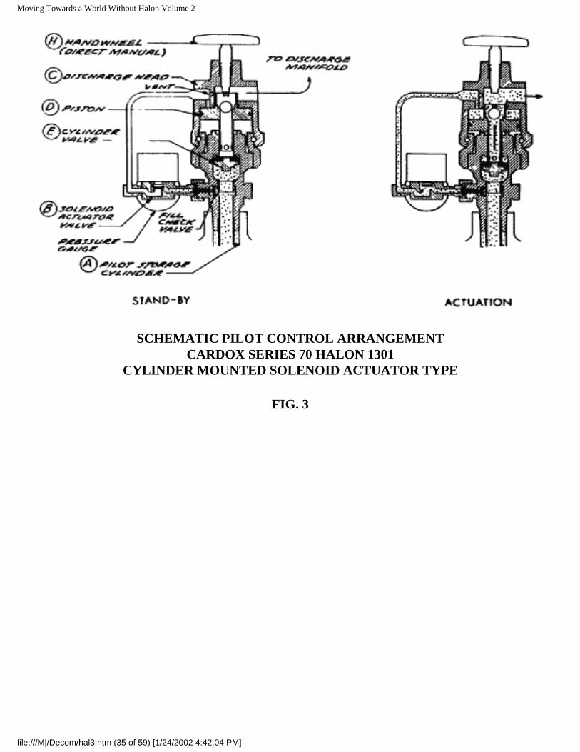
Cylinder Mounted Solenoid Actuator Type (Figure 3): Automatic actuation is powered by vapor pressure from the one or more pilot storage cylinders (A). Pilot pressure is applied continuously to a normally closed solenoid actuator valve (B), with pressure gauge, through its attachment to the fill-check connection at the neck of the pilot cylinder. The solenoid actuator is connected by a wiring circuit to detection devices in the protected area. A signal from a detection device causes the solenoid actuator valve to open and apply pilot cylinder vapor pressure to the discharge head (C). Pressure above the discharge head piston (D) causes the piston to move down to unseat the cylinder valve (E), permitting a discharge from the cylinder to the cylinder manifold. Manifold pressure acting on the pistons of the discharge heads of the remaining connected cylinders causes them to discharge. The discharge heads are self-energizing and hold the cylinder valve open while the cylinder discharges completely. A vent in the discharge head prevents accidental operation of a discharge head in case of leakage through the solenoid actuator valve.
The piston of all cylinder heads has a ratio of 9 to 1 to insure proper function under all pressure conditions.
Selector Valves: When selector valves are used to permit a single cylinder bank to serve more than one protected area, a pressure operated 3-way pilot valve is provided for each selector valve. Pilot pressure for operation of the selector valve is normally taken from the discharge manifold. The pilot manifold pressure or control cylinder pressure.
file:///M|/Decom/hal3.htm (34 of 59) [1/24/2002 4:42:04 PM]
Moving Towards a World Without Halon Volume 2
SCHEMATIC PILOT CONTROL ARRANGEMENTCARDOX SERIES 70 HALON 1301
CYLINDER MOUNTED SOLENOID ACTUATOR TYPE
FIG. 3
file:///M|/Decom/hal3.htm (35 of 59) [1/24/2002 4:42:04 PM]
Moving Towards a World Without Halon Volume 2
CARDOX CYLINDER VALVESERIES 70
TYPE IM CLASS CMPART NO.1-061-0730MODEL NO. C50401
PLATE H-27A
file:///M|/Decom/hal3.htm (36 of 59) [1/24/2002 4:42:04 PM]
Moving Towards a World Without Halon Volume 2
file:///M|/Decom/hal3.htm (37 of 59) [1/24/2002 4:42:04 PM]
Moving Towards a World Without Halon Volume 2
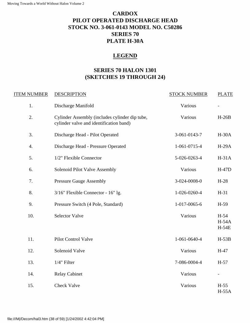
CARDOXPILOT OPERATED DISCHARGE HEAD
STOCK NO. 3-061-0143 MODEL NO. C50286SERIES 70
PLATE H-30A
LEGEND
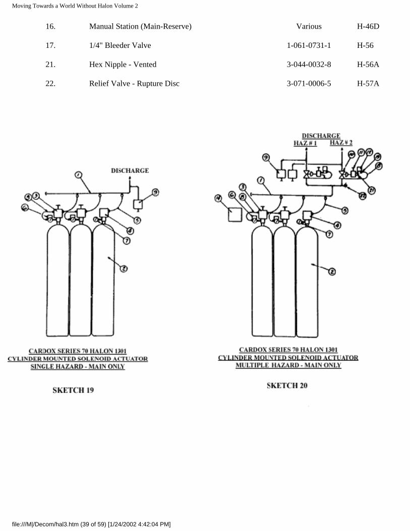
SERIES 70 HALON 1301(SKETCHES 19 THROUGH 24)
ITEM NUMBER DESCRIPTION STOCK NUMBER PLATE
1. Discharge Manifold Various -
2. Cylinder Assembly (includes cylinder dip tube, cylinder valve and identification band)
Various H-26B
3. Discharge Head - Pilot Operated 3-061-0143-7 H-30A
4. Discharge Head - Pressure Operated 1-061-0715-4 H-29A
5. 1/2" Flexible Connector 5-026-0263-4 H-31A
6. Solenoid Pilot Valve Assembly Various H-47D
7. Pressure Gauge Assembly 3-024-0008-0 H-28
8. 3/16" Flexible Connector - 16" lg. 1-026-0260-4 H-31
9. Pressure Switch (4 Pole, Standard) 1-017-0065-6 H-59
10. Selector Valve Various H-54H-54AH-54E
11. Pilot Control Valve 1-061-0640-4 H-53B
12. Solenoid Valve Various H-47
13. 1/4" Filter 7-086-0004-4 H-57
14. Relay Cabinet Various -
15. Check Valve Various H-55H-55A
file:///M|/Decom/hal3.htm (38 of 59) [1/24/2002 4:42:04 PM]
Moving Towards a World Without Halon Volume 2
16. Manual Station (Main-Reserve) Various H-46D
17. 1/4" Bleeder Valve 1-061-0731-1 H-56
21. Hex Nipple - Vented 3-044-0032-8 H-56A
22. Relief Valve - Rupture Disc 3-071-0006-5 H-57A
file:///M|/Decom/hal3.htm (39 of 59) [1/24/2002 4:42:04 PM]
Moving Towards a World Without Halon Volume 2
file:///M|/Decom/hal3.htm (40 of 59) [1/24/2002 4:42:04 PM]
Moving Towards a World Without Halon Volume 2
CHEMETRON HIGH FLOW-360HALON 1301 SYSTEMS
SECTION 1CGENERAL DESCRIPTION
HIGH FLOW-360 MODEL BHALON 1301 SYSTEMS
GENERAL
Each Fire Systems halon 1301 system is specifically engineered to accommodate the individual demands of the areas to be protected. The wide range and design of available components provides the flexibility necessary for this custom design. The use of multiple storage cylinders and selector valves enables a single group of cylinders to serve more than one protected area on an individual basis.
file:///M|/Decom/hal3.htm (41 of 59) [1/24/2002 4:42:04 PM]
Moving Towards a World Without Halon Volume 2
Fire Systems offers three series of storage components, namely the High Flow Series 360, Series 600, and Series 70. Although the basic function is the same in each series, the components and their arrangements differ somewhat. This section covers the High Flow-360, Model B System.
The High Flow 360 system permits higher discharge rates and is particularly adaptable to areas involving larger quantities of halon 1301 or short discharge duration. However, due to the lower storage pressure, the length of pipe run to the nozzles is more limited than is the case with the High Flow 600 System.
The High Flow 360, Model B System utilizes storage cylinders having generally greater capacity than the High Flow 600 system. The cylinders are secured in a rack or racks and the discharge outlets are manifolded together in groups of up to four cylinders. Each system must include at least one pilot cylinder since the pilot cylinder serves to initiate the discharge of all other cylinders (slave cylinders) in the system. Two pilot cylinders are recommended for systems involving two or more cylinders, however, for redundancy to provide greater reliability.
Two pilot cylinders must be used for systems having in excess of 12 cylinders. A booster pilot cylinder must be included for each 12 cylinders in excess of 24 cylinders. A booster pilot cylinder is the same as a normal pilot cylinder except that the Solenoid Pilot Valve Assembly is eliminated. The 3/16" Flexible Connector from the "B" port of the Manual-pneumatic Actuator is eliminated and the "B" port is capped with a flare cap. Generally the booster pilot cylinder is located adjacent to the normal pilot cylinders although there may be cases where the booster pilot is located differently due to unusual cylinder bank arrangement.
A series of sketches illustrating typical system arrangements and a companion list of equipment are provided in this section. Sketches 29, 30, 31, and 32 cover arrangements for a system protecting a single area, with and without connected reserve cylinders.
These basic system can be modified to serve two or more protected areas by the addition of Selector Valves and the necessary related control devices. Sketch 33 illustrates this modification as applied to the system shown in Sketch 32. The above referenced Sketches Include only one pilot cylinder for each cylinder bank. As previously mentioned, two are recommended for complete redundancy of piloting devices. Sketch 34 illustrates how the system shown in Sketch 31 is modified to provide the dual pilot cylinder feature. A second pilot cylinder is adaptable to any system in the same manner. The same Pilot arrangement applies to the booster pilot of large systems, the only difference being the elimination of the Solenoid Pilot Valve Assembly and Flexible Connector as previously described.
Additional Sketches 35, 36, and 37 are included to provide more detailed information on the pilot controls and cylinder interconnections for both single and dual pilot arrangements.
A description of the various equipment components is included in the following paragraphs:
file:///M|/Decom/hal3.htm (42 of 59) [1/24/2002 4:42:04 PM]
Moving Towards a World Without Halon Volume 2
Cylinder Assembly: (Plate H-26E)
Halon 1301 is stored in specially designed cylinder assemblies. These are available in a number of capacities and are charged with halon 1301 to a filling-density up to 70 pounds per cubic foot of cylinder volume. The cylinders are super-pressurized with dry nitrogen to a pressure of 360 psig (±5%) at 70ºF. Each cylinder is equipped with an identification nameplate indicating the quantity of halon, and an adhesive cylinder label indicating the halon liquid level.
The cylinder assembly is composed of a cylinder, a dip tube, and a cylinder valve.
Cylinder: The steel cylinders are manufactured to the requirements of the D.O.T. for compressed gas and have internal neck threads for cylinder valve connection.
Dip Tube: A threaded dip tube extends from the cylinder valve down to within approximately 1½" of the bottom of the cylinder. The steel tube has a 2.375 in. O.D. and .125 it. wall thickness. The threads are 2.375-12UN-2A.
Cylinder Valve: (Plate H-27E) A pressure "release" type cylinder valve having a forged brass body is attached to the cylinder neck and serves to control the flow of halon from the cylinder. The valve is secured to the cylinder by means of 4.5-12UN-2A screw threads and is sealed by a cylinder "O" ring. A synthetic rubber seat is attached to a steel seat retainer which is screwed into the bottom of the valve. The seat retainer also supports the dip tube.
The cylinder valve has five connections as follows:
a. Manual-pneumatic Actuator Connection: This is a threaded connection housing a check valve and serves as the attachment point for the Manual-pneumatic Actuator on those cylinders used for piloting other cylinders (Pilot Cylinder). on other than pilot cylinders, this connection is not normally utilized.
b. Pressure Gauge/Solenoid Pilot Valve Assembly Connection: This is a threaded connection housing a check valve and serves for the attachment of:
1. Solenoid Pilot Valve Assembly (with pressure gauge) for pilot cylinders; and2. Pressure Gauge Assembly for all other cylinders of the system.
c. Pneumatic Actuator Connection: This is a threaded connection housing a check valve located on
top of the cylinder valve. It serves as an attachment point for the Pneumatic Actuator on all cylinders. WARNING: IF THIS CONNECTION IS LOOSENED SO AS TO RELEASE PRESSURE FROM ABOVE THE MAIN OPERATING PISTON, THE CYLINDER WILL DISCHARGE. NEVER ATTACH THE SOLENOID PILOT VALVE ASSEMBLY OR THE PRESSURE GAUGE ASSEMBLY TO THIS CONNECTION FOR THIS COULD CAUSE THE CYLINDER TO DISCHARGE.
NOTE: The connection described under a, b, and c above are threaded inserts ½" NPT) in the
file:///M|/Decom/hal3.htm (43 of 59) [1/24/2002 4:42:04 PM]
Moving Towards a World Without Halon Volume 2
cylinder valve body and are replaceable (provided cylinder is empty) if faulty or if external threads are damaged, etc.
d. Safety Disc Connection: A rupture safety disc is located at this threaded connection and serves to protect the cylinder against excessive internal pressure. The disc is designed to burst in a range of 850 to 1000 psi.
e. Discharge Connection: This connection (2" nominal pipe size) is in the form of an outlet fitting which threads into the valve body and is sealed with an "O" ring. The exposed end is grooved for attachment of grooved fittings ("Victaulic", etc.). The outlet fitting can be removed for replacement if necessary.
Discharge Connection Fittings: (Plate H-31E)
A 2" grooved elbow, nipple and companion couplings and gaskets are used to extend the discharge outlet fitting of the cylinder valve to the piping system.
These fittings ease the assembly and accommodate some minor differences in alignment. The treatment of single cylinder and multi-cylinder systems varies as follows:
Multi-cylinder Systems: Where two or more cylinders are to be connected to a common discharge piping system, a 2" check valve must be included in the connection at each cylinder. Further, a discharge manifold with a connection point for each cylinder is required.
Single Cylinder Systems: Where only one cylinder is connected to a discharge piping system, a check valve is not required.
Check Valve: (Plate H-55G)
A Check Valve is used between the cylinder valve discharge outlet (connection fittings) and the discharge manifold. The Check Valve prevents back flow from the manifold in the event that the system is discharged when one or more cylinders are disconnected such as for weighing or general servicing. On single cylinder systems a Check Valve is not required.
Solenoid Pilot Valve Assembly: (Plate H-47J)
The system utilizes a Solenoid Pilot Valve Assembly to provide pilot pressure for actuation whether system actuation is automatic by fire detection device or by manual-electric release station. The assembly comes in various voltages.
The Solenoid Pilot Valve Assembly includes a pressure gauge and adapter with swivel nut and "O" ring seal which is attached to the appropriate connection of the cylinder valve. The adapter includes a probe
file:///M|/Decom/hal3.htm (44 of 59) [1/24/2002 4:42:04 PM]
Moving Towards a World Without Halon Volume 2
which upsets the check valve when the swivel nut is almost tight at which time the "O" ring seal prevents agent loss. With the check valve open, pilot cylinder pressure is applied to the normally closed solenoid valve and the pressure gauge. The pressure gauge provides for visual surveillance of the pressure condition within the cylinder. Actuation of the Solenoid Pilot Valve Assembly permits pressure to be applied through a Flexible Connector to the Manual-pneumatic Actuator which in turn applies pilot cylinder pressure to its Pneumatic Actuator and to the Pneumatic Actuators of any other cylinders to be discharged simultaneously.
The Solenoid Pilot Valve Assembly can be removed for servicing or testing without significant loss of agent since the check valve will close when the assembly is removed.
A flexible electrical conduit is required between the solenoid valve and the system conduit. The flexibility facilitates cylinder weighing and servicing.
Manual-pneumatic Actuator: (Plate H-47B)
This device attaches to one or more of the cylinders of a cylinder group which are called pilot cylinders. This is a dual purpose device having an actuating Piston connected to a probe to upset the connection check valve when pilot pressure is applied to the piston. With the check open, cylinder pressure is applied through flexible connector to the Pneumatic Actuator of its cylinder valve, and in turn to the Pneumatic Actuators of any other cylinders to be discharged simultaneously opening the cylinder valves to discharge their contents. The Manual-pneumatic Actuator piston area to check valve area ratio is about 10 to 1 thereby insuring actuation even with reduced pilot pressure.
A manual lever and cam arrangements on the Manual-pneumatic Actuator permits actuation of the device on a manual basis, thereby overriding and independent of electric power of pilot pressure. It is used to operate the system in cases where a fire is detected visually before the fire detecting devices operate or a power failure occurs. A pull-pin and seal prevents accidental operation of the manual lever. It must be manually reset.
A swivel nut and "O" ring seal on the device provides for attachment and seal at the connection point.
Pneumatic Actuator: (Plate H- 47H)
This device attaches to the connection on top of the cylinder valve and is the final step in pilot operation to open the cylinder valve. It has a piston connected to a probe to upset the connection check valve when pilot pressure is applied to the piston. With the check valve open, pressure above the piston of the cylinder valve is rapidly vented to atmosphere, thereby causing the cylinder valve to open.
The Pneumatic Actuator is designed to reset automatically when pilot pressure is removed. The Pneumatic Actuator piston area to check valve area ratio is approximately 10 to 1, hence actuation is assured even with reduced pilot pressure.
file:///M|/Decom/hal3.htm (45 of 59) [1/24/2002 4:42:04 PM]
Moving Towards a World Without Halon Volume 2
Pressure Gauge Assembly: (Plate H-28A)
A Pressure Gauge Assembly is provided for each cylinder other than the pilot cylinders to provide a means of visual surveillance of the pressure condition within the cylinder. The assembly contains a swivel nut and "O" ring seal for attachment to a connection on the cylinder valve. A probe in the assembly upsets the connection check valve when the swivel nut is almost tight at which time the "O" ring seal prevents agent loss. The Pressure Gauge Assembly can be removed for replacement or checking without any significant loss of agent since the gauge check valve closes as the gauge assembly is removed.
Flexible Connectors: (Plate H-31)
Lengths of 3/16 in. armored Flexible Connectors are used to interconnect the Pneumatic Actuators. These connectors have a stainless steel wire braid cover and a teflon liner and are fitted at each end with a ¼ in. swivel flare nut.
Manifolds: (Plates H-36K and H-36L)
Steel pipe manifold assemblies (Schedule 40) are supplied in either 2½ in. or 3 in. pipe sizes depending on the cylinder sizes being used in the system. Both sizes are available with either center or end outlets.
Selector Valves: (Plates H-54, H-54A, and H-54E)
Systems protecting more than one area on an individual basis require Selector Valves to direct the discharged halon 1301 into the desired area. The Selector Valves are available in various sizes from ½ in. through 6 in. The Sizes up through 2 in. have bronze bodies and caps. The larger sizes are cast steel. All are pressure operated, having a seat disc and disc carrier connected by a stem to a piston. Application of pilot pressure from an associated Pilot Control Valve to the Selector Valve piston causes the Selector Valve to open and remain open until pilot pressure above the piston is exhausted.
Pilot Control Valve: (Plate H-53B)
A Pilot Control Valve is used to provide the pilot pressure for each Selector Valve. The valve has a forged brass body with brass and stainless trim parts. The valve is pressure operated having a two part piston connected by a stem to a disc carrier and seat disc. The two part piston serves to lock the valve in the open position until pressure within the valve is depleted when the cylinders have emptied. Pressure for piloting the Pilot Control Valve is supplied from the discharge manifold. It is applied to the chamber above the Pilot Control Valve piston by means of a two-way solenoid valve and filter. Pilot pressure for actuating the Selector Valve is supplied from the discharge manifold through the Pilot Control Valve. A handwheel is provided on the valve for manual operation in case of a power failure.
file:///M|/Decom/hal3.htm (46 of 59) [1/24/2002 4:42:04 PM]
Moving Towards a World Without Halon Volume 2
Hex Nipple--Vented: (Plate H-56A)
A vented Hex Nipple is used to connect a solenoid valve to port "A" of a Pilot Control Valve. The small vent hole is used to bleed off any pressure which could otherwise accumulate and result in a false valve operation.
Shuttle Valve: (Plate H-38)
Shuttle Valves (double check valves) are used in some pilot line arrangements to isolate sections of the pilot lines when certain sections are common to several areas. The Shuttle Valve is in effect a tee which permits two inlet lines to converge into a common side outlet. Pressure at one inlet moves an internal shuttle to seal off the other inlet.
Pressure Switch: (Plates H-59, H-59A, and H-59B)
Pressure Switches are used in the system to implement the shut-down of various items of equipment such as fans, power supplies, and for annunciation and alarm purposes.
Pressure Release: (Plate H-58)
Pressure Releases are used for closing doors, dampers, etc., on actuation of the system. They have an internal piston and an external spring clip to which is attached a cable or chain to hold the released device in the open position. The Pressure Releases are generally connected by piping to the discharge piping. Pressure from the discharge forces the piston forward in the release thereby releasing the spring clip and permitting the released device to close.
Discharge Delay Devices:
In most instances the discharge from automatic means (detection devices) is delayed for a pre-discharge warning period. This is formally accomplished electrically by including a time delay relay or a timer in the automatic actuation circuit. The electrical impulse from a detection device is delayed from reaching the solenoid valve on the pilot cylinder for a predetermined period, during which an alarm is sounded to alert personnel.
Electrical Remote Manual Release: (Various)
These devices are located at one or more doors to the protected area to provide a manual means of actuating the system in the event a fire is observed by personnel prior to detection device response. Several types are available, although the most common is a pushbutton station with a breakglass device to preclude accidental operation, or a toggle switch station with a pull pin and seal to preclude accidental operation.
file:///M|/Decom/hal3.htm (47 of 59) [1/24/2002 4:42:04 PM]
Moving Towards a World Without Halon Volume 2
Operation of a release energizes the solenoid valve on the pilot cylinder valve either directly or indirectly through a relay and causes system actuation.
Fire Detection Devices:
Automatic actuation of a system can be provided by using any one of a number of Underwriters' Laboratories listed and Factory Mutual approved detection devices such as ionization products of combustion devices, smoke detection devices, thermal switches, etc., depending on the nature of fires which can be predicted for an area. Sometimes more than one type are used to provide the most positive response. All involve the transmission of an electrical impulse which energizes the solenoid valve on the pilot cylinder, either directly or through a relay, and causes system actuation.
Bleeder Valve: (Plate H-56)
Bleeder Valves are used in the pilot connection of one of a group of cylinders to prevent accumulation of pressure due to accidental leakage through a device, which if unvented could cause the system to discharge. The valve is normally open to atmosphere and closes at approximately 50 psi when full pilot pressure is applied on normal system operation.
Description of System Operation
Automatic Actuation
Pilot Cylinder Actuation: (Figures 5 and 6)
The valve is designed to have equal pressure both above and below the piston (A) in normal mode. The greater area of pressure exposure on top of the piston compared with that below provides the force in combination with the spring (B) force to maintain the piston in sufficient contact with the elastomer seat (C) to provide a tight seal. An "O" ring (D) around the outer surface of the piston provides a seal between the piston and the valve body inner surface thereby preventing loss of agent to the discharge area.
Cylinder vapor pressure is applied to the space above the Piston through a filter (E) and passage at the base of the piston. The annular area around the stainless steel ball (F) provides a limiting orifice area between the cylinder and space above the piston. The passage permits equalization of pressure above and below the piston due to changes in cylinder pressure in response to ambient temperature changes. Flow through the passage under this condition is not sufficient to cause the ball to block the passage.
Figures 5 and 6 illustrate diagrammatically the two valve modes, namely "Stand-by" where the valve is available for actuation and "Automatic Actuation" where the valve has been actuated electrically from a fire detection system or from an electric manual release station. A description is as follows:
Stand-by - In this mode equal pressure exists above and below the piston. Pressure is
file:///M|/Decom/hal3.htm (48 of 59) [1/24/2002 4:42:04 PM]
Moving Towards a World Without Halon Volume 2
exposed to the solenoid valve and pressure gauge of the Solenoid Pilot Valve Assembly (G). Pressure is also exposed to the check valve related to the Manual-pneumatic Actuator (H) and Pneumatic Actuator (J). The outlet of the solenoid valve is connected by a 3/16 in. armored Flexible Connector (K) to the "B" port of the Manual-pneumatic Actuator. The "A" port of the Manual-pneumatic Actuator is connected to the Pneumatic Actuator by another 3/16 in. armored Flexible Connector (L).
Automatic Actuation - Pilot Cylinder: The solenoid valve is energized by the system detection system or electric manual release station causing it to open to apply pressure through port "B" of the Manual-pneumatic Actuator (H) to its piston. This in turn causes the piston to move to unseat the check valve. With the check valve open, cylinder pressure supply in greater capacity is applied through port "A" to the piston of the Pneumatic Actuator (J) at the top of the Pilot Cylinder Valve and to the Pneumatic Actuators of any other cylinders which are to be simultaneously discharged. This pressure forces the Pneumatic Actuator piston down so that its probe unseats the check valve which in turn results in venting pressure rapidly from above the piston of the cylinder valve. Reduced pressure above the piston enables cylinder pressure below the piston to force the piston up, resulting in discharge of agent from the cylinder. Complete evacuation of the cylinder depends on a raised piston which in turn requires maintaining a reduced pressure above the piston. As previously mentioned, this is assured by the fact that the Manual-pneumatic Actuator locks itself in actuation mode once it is actuated either pneumatically by the Solenoid Pilot Actuator or manually by its own actuation lever.
Manual Actuation - Pilot Cylinder: The events described for automatic actuation are the same for manual actuation except that the solenoid valve is not actuated. The manual actuating lever of the Manual-pneumatic Actuator is used to manually actuate the system.
Actuation - Other Than Pilot Cylinders: All cylinders other than pilot cylinders are called "slave" cylinders. The valves for these are identical in operation to those of pilot cylinders but include a Pressure Gauge Assembly and are not equipped with a Solenoid Pilot Valve Assembly or a Manual-pneumatic Actuator. The valve is opened by the application of pilot pressure from a pilot cylinder to the Pneumatic Actuator. Valve operation is the same as described above the pilot cylinder.
CHEMETRON fire extinguishing equipment
NOTE: INCLUDED AS PART OF THE VALVE BUT NOT SHOWN IS A 2" VICTAULIC COUPLING 7-39-0343, A VICTAULIC CAP 3-061-1158 AND A ANTI-RECOIL PLUG 3-061-0590
file:///M|/Decom/hal3.htm (49 of 59) [1/24/2002 4:42:04 PM]
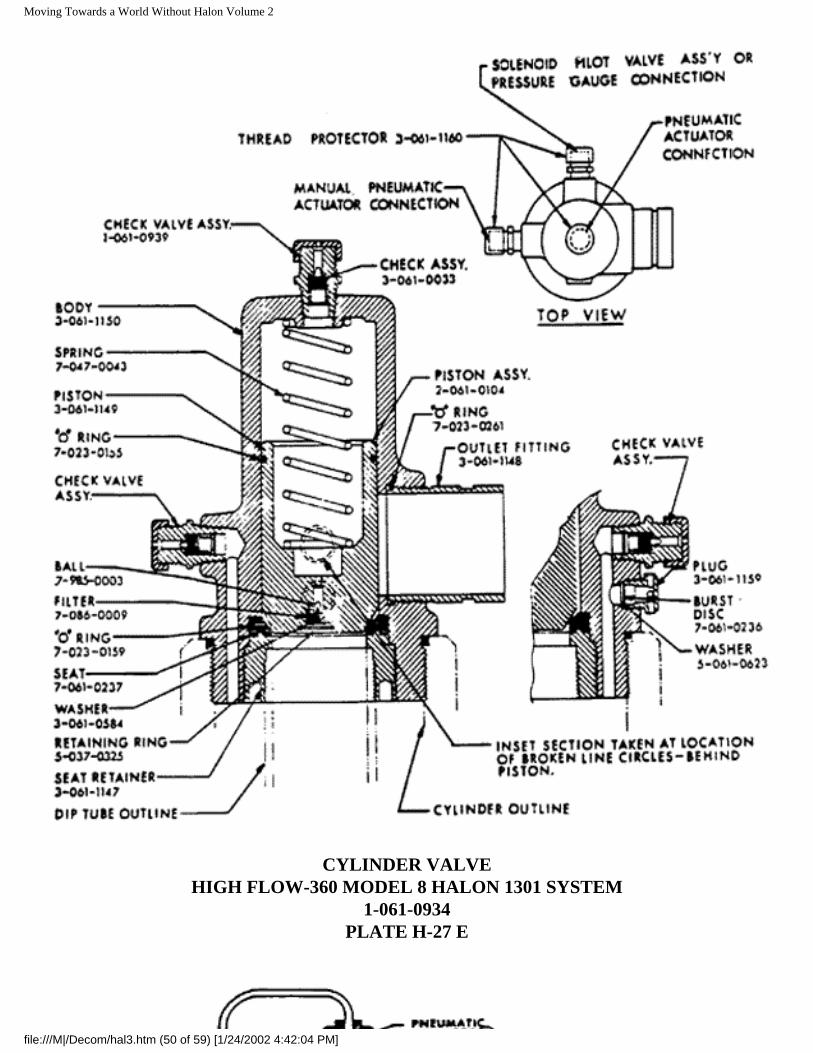
Moving Towards a World Without Halon Volume 2
CYLINDER VALVE
HIGH FLOW-360 MODEL 8 HALON 1301 SYSTEM1-061-0934
PLATE H-27 E
file:///M|/Decom/hal3.htm (50 of 59) [1/24/2002 4:42:04 PM]
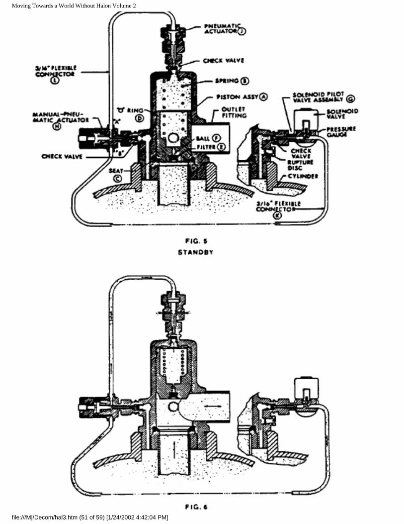
Moving Towards a World Without Halon Volume 2
file:///M|/Decom/hal3.htm (51 of 59) [1/24/2002 4:42:04 PM]
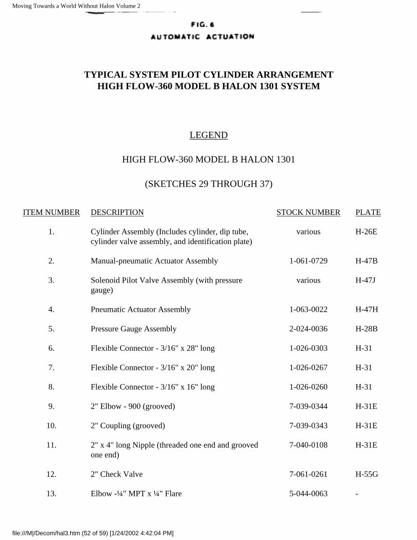
Moving Towards a World Without Halon Volume 2
TYPICAL SYSTEM PILOT CYLINDER ARRANGEMENTHIGH FLOW-360 MODEL B HALON 1301 SYSTEM
LEGEND
HIGH FLOW-360 MODEL B HALON 1301
(SKETCHES 29 THROUGH 37)
ITEM NUMBER DESCRIPTION STOCK NUMBER PLATE
1. Cylinder Assembly (Includes cylinder, dip tube, cylinder valve assembly, and identification plate)
various H-26E
2. Manual-pneumatic Actuator Assembly 1-061-0729 H-47B
3. Solenoid Pilot Valve Assembly (with pressure gauge)
various H-47J
4. Pneumatic Actuator Assembly 1-063-0022 H-47H
5. Pressure Gauge Assembly 2-024-0036 H-28B
6. Flexible Connector - 3/16" x 28" long 1-026-0303 H-31
7. Flexible Connector - 3/16" x 20" long 1-026-0267 H-31
8. Flexible Connector - 3/16" x 16" long 1-026-0260 H-31
9. 2" Elbow - 900 (grooved) 7-039-0344 H-31E
10. 2" Coupling (grooved) 7-039-0343 H-31E
11. 2" x 4" long Nipple (threaded one end and grooved one end)
7-040-0108 H-31E
12. 2" Check Valve 7-061-0261 H-55G
13. Elbow -¼" MPT x ¼" Flare 5-044-0063 -
file:///M|/Decom/hal3.htm (52 of 59) [1/24/2002 4:42:04 PM]
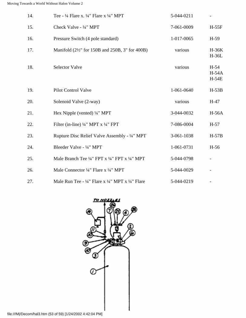
Moving Towards a World Without Halon Volume 2
14. Tee - ¼ Flare x. ¼" Flare x ¼" MPT 5-044-0211 -
15. Check Valve - ¼" MPT 7-061-0009 H-55F
16. Pressure Switch (4 pole standard) 1-017-0065 H-59
17. Manifold (2½" for 150B and 250B, 3" for 400B) various H-36K H-36L
18. Selector Valve various H-54H-54AH-54E
19. Pilot Control Valve 1-061-0640 H-53B
20. Solenoid Valve (2-way) various H-47
21. Hex Nipple (vented) ¼" MPT 3-044-0032 H-56A
22. Filter (in-line) ¼" MPT x ¼" FPT 7-086-0004 H-57
23. Rupture Disc Relief Valve Assembly - ¼" MPT 3-061-1038 H-57B
24. Bleeder Valve - ¼" MPT 1-061-0731 H-56
25. Male Branch Tee ¼" FPT x ¼" FPT x ¼" MPT 5-044-0798 -
26. Male Connector ¼" Flare x ¼" MPT 5-044-0029 -
27. Male Run Tee - ¼" Flare x ¼" MPT x ¼" Flare 5-044-0219 -
file:///M|/Decom/hal3.htm (53 of 59) [1/24/2002 4:42:04 PM]
Moving Towards a World Without Halon Volume 2
file:///M|/Decom/hal3.htm (54 of 59) [1/24/2002 4:42:04 PM]
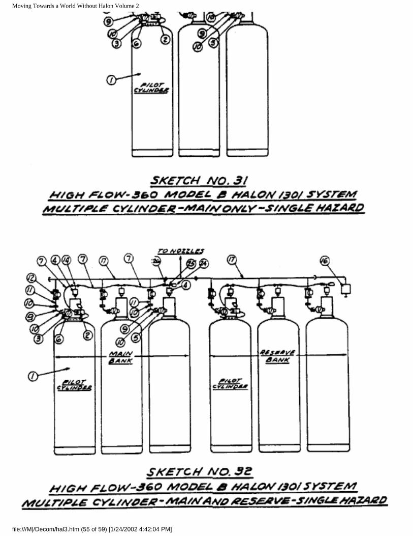
Moving Towards a World Without Halon Volume 2
file:///M|/Decom/hal3.htm (55 of 59) [1/24/2002 4:42:04 PM]
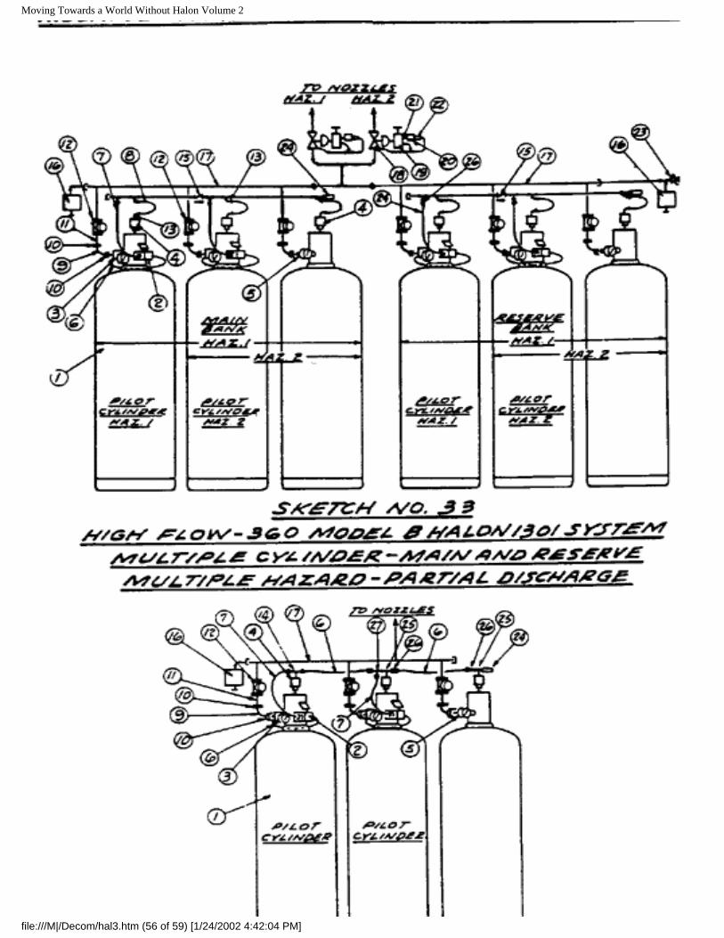
Moving Towards a World Without Halon Volume 2
file:///M|/Decom/hal3.htm (56 of 59) [1/24/2002 4:42:04 PM]
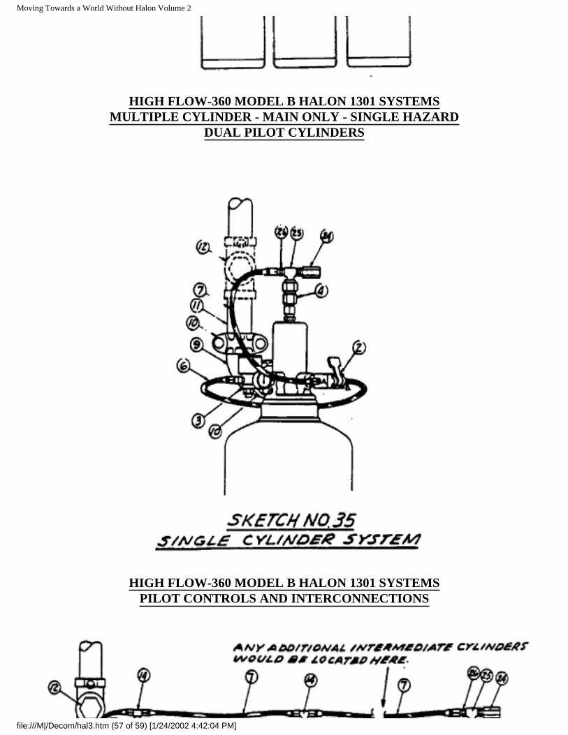
Moving Towards a World Without Halon Volume 2
HIGH FLOW-360 MODEL B HALON 1301 SYSTEMSMULTIPLE CYLINDER - MAIN ONLY - SINGLE HAZARD
DUAL PILOT CYLINDERS
HIGH FLOW-360 MODEL B HALON 1301 SYSTEMSPILOT CONTROLS AND INTERCONNECTIONS
file:///M|/Decom/hal3.htm (57 of 59) [1/24/2002 4:42:04 PM]
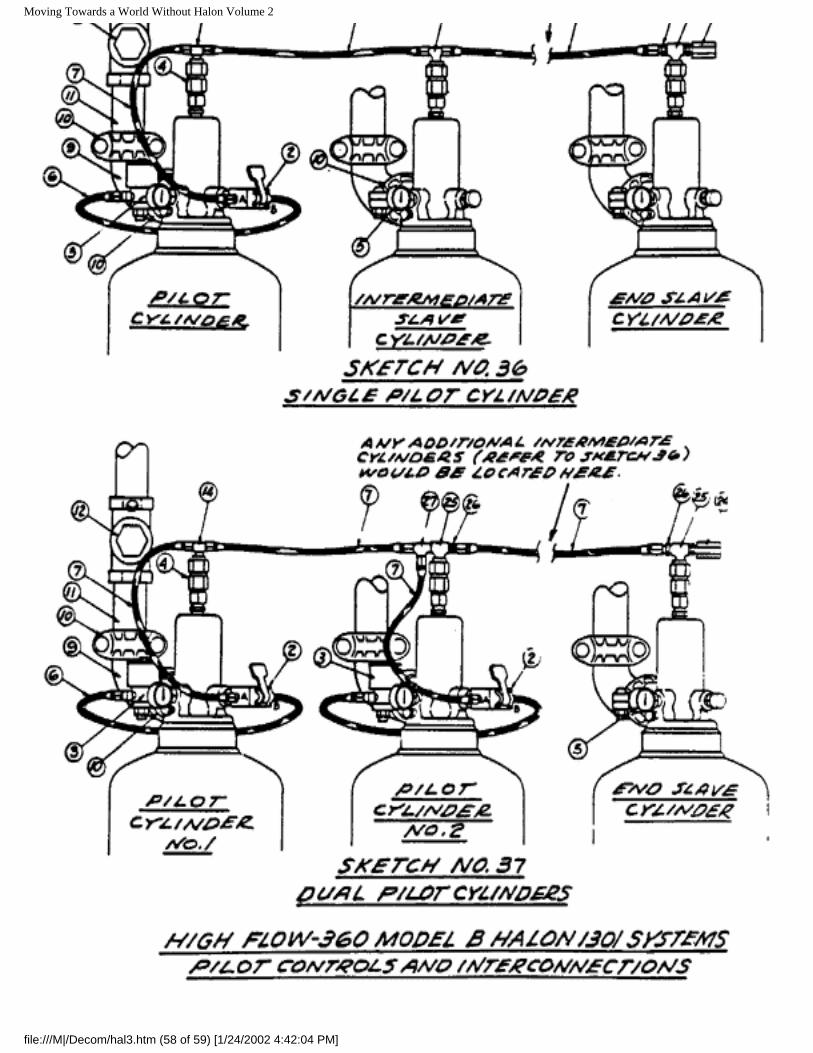
Moving Towards a World Without Halon Volume 2
file:///M|/Decom/hal3.htm (58 of 59) [1/24/2002 4:42:04 PM]