Embed Size (px)
Citation preview
Freescale SemiconductorApplication Note
© Freescale Semiconductor, Inc., 2003, 2006. All rights reserved.
This application note is a supplement to the MPC184 8xx Security Co-Processor User’s Manual, to assist programmers in understanding and creating descriptors. The information in this note includes more specific requirements than those that the MPC184 device driver covers. This application note is more useful to programmers who are familiar with the basics of MPC184 architecture in the user’s manual. All descriptor and execution unit references are shown in big endian format consistent with the 8xx version of the MPC184 user’s manual.
Document Number: AN2576Rev. 1, 10/2006
Contents1. Data Packet Descriptor Overview . . . . . . . . . . . . . . . . 22. Descriptor Structure . . . . . . . . . . . . . . . . . . . . . . . . . . 23. Descriptor Header . . . . . . . . . . . . . . . . . . . . . . . . . . . . 34. Execution Unit Mode Data . . . . . . . . . . . . . . . . . . . . . 55. Descriptor Type Field . . . . . . . . . . . . . . . . . . . . . . . . 146. Descriptor Length and Pointer Fields . . . . . . . . . . . . 187. Descriptor Chaining . . . . . . . . . . . . . . . . . . . . . . . . . 208. Descriptor Classes . . . . . . . . . . . . . . . . . . . . . . . . . . . 219. Additional Examples . . . . . . . . . . . . . . . . . . . . . . . . . 24
10. SSLv3.1/TLS1.0 Processing . . . . . . . . . . . . . . . . . . . 3411. Conclusion . . . . . . . . . . . . . . . . . . . . . . . . . . . . . . . . 3812. Revision History . . . . . . . . . . . . . . . . . . . . . . . . . . . . 39
MPC184 Descriptor Programmer’s Guide—8xx Viewby Geoff Waters, Security Applications
Michael Torla, Security DesignFreescale Semiconductor, Inc.Austin, TX
MPC184 Descriptor Programmer’s Guide—8xx View, Rev. 1
2 Freescale Semiconductor
Data Packet Descriptor Overview
1 Data Packet Descriptor OverviewThe MPC184 has bus mastering capability on either 32-bit PCI or the PowerQUICC™ 8xx bus to off load data movement and encryption operations from a host processor. As the system controller, the host processor maintains a record of current secure sessions and the corresponding keys and contexts of those sessions. When the host determines that a security operation is required, the host can either directly write keys, context, and data to the MPC184 (MPC184 in target mode), or it can create a 'data packet descriptor' to guide the MPC184 through the security operation, with the MPC184 acting as a bus master. The descriptor can be created in main memory, any memory local to the MPC184, including 8 Kbytes of on-chip gpRAM, or written directly to the data packet descriptor buffer in the MPC184 crypto-channel.
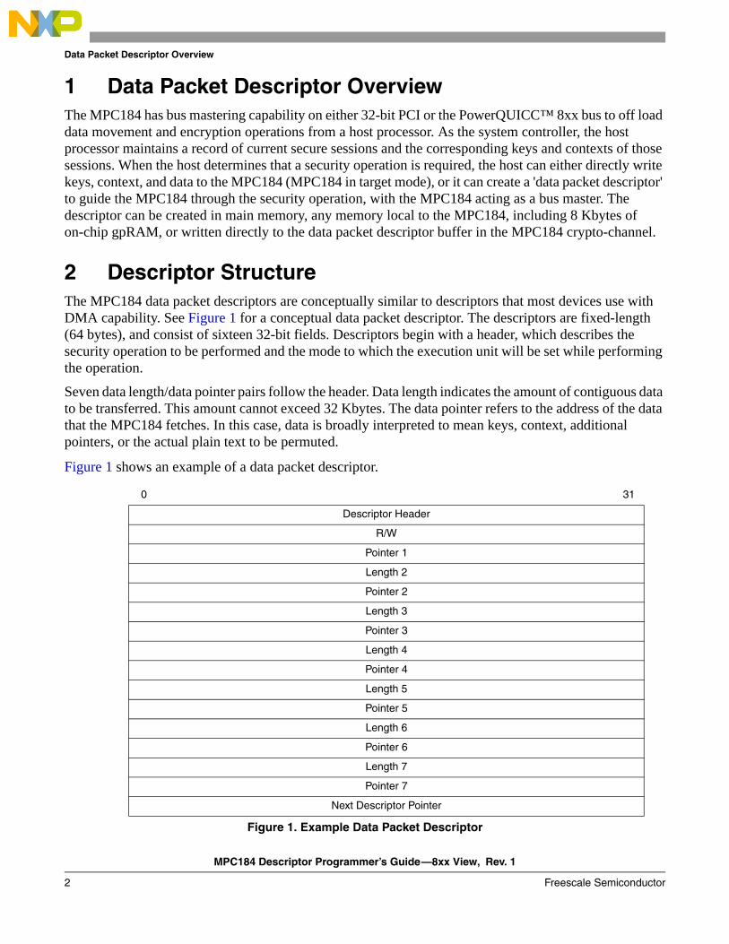
2 Descriptor StructureThe MPC184 data packet descriptors are conceptually similar to descriptors that most devices use with DMA capability. See Figure 1 for a conceptual data packet descriptor. The descriptors are fixed-length (64 bytes), and consist of sixteen 32-bit fields. Descriptors begin with a header, which describes the security operation to be performed and the mode to which the execution unit will be set while performing the operation.
Seven data length/data pointer pairs follow the header. Data length indicates the amount of contiguous data to be transferred. This amount cannot exceed 32 Kbytes. The data pointer refers to the address of the data that the MPC184 fetches. In this case, data is broadly interpreted to mean keys, context, additional pointers, or the actual plain text to be permuted.
Figure 1 shows an example of a data packet descriptor.
0 31
Descriptor Header
R/W
Pointer 1
Length 2
Pointer 2
Length 3
Pointer 3
Length 4
Pointer 4
Length 5
Pointer 5
Length 6
Pointer 6
Length 7
Pointer 7
Next Descriptor Pointer
Figure 1. Example Data Packet Descriptor
MPC184 Descriptor Programmer’s Guide—8xx View, Rev. 1
Freescale Semiconductor 3
Descriptor Header
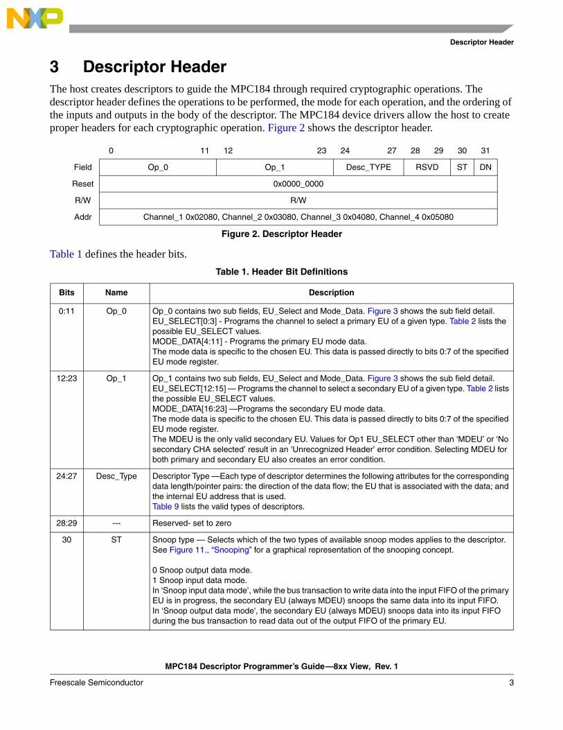
3 Descriptor HeaderThe host creates descriptors to guide the MPC184 through required cryptographic operations. The descriptor header defines the operations to be performed, the mode for each operation, and the ordering of the inputs and outputs in the body of the descriptor. The MPC184 device drivers allow the host to create proper headers for each cryptographic operation. Figure 2 shows the descriptor header.
Table 1 defines the header bits.
0 11 12 23 24 27 28 29 30 31
Field Op_0 Op_1 Desc_TYPE RSVD ST DN
Reset 0x0000_0000
R/W R/W
Addr Channel_1 0x02080, Channel_2 0x03080, Channel_3 0x04080, Channel_4 0x05080
Figure 2. Descriptor Header
Table 1. Header Bit Definitions
Bits Name Description
0:11 Op_0 Op_0 contains two sub fields, EU_Select and Mode_Data. Figure 3 shows the sub field detail.EU_SELECT[0:3] - Programs the channel to select a primary EU of a given type. Table 2 lists the possible EU_SELECT values.MODE_DATA[4:11] - Programs the primary EU mode data.The mode data is specific to the chosen EU. This data is passed directly to bits 0:7 of the specified EU mode register.
12:23 Op_1 Op_1 contains two sub fields, EU_Select and Mode_Data. Figure 3 shows the sub field detail.EU_SELECT[12:15] — Programs the channel to select a secondary EU of a given type. Table 2 lists the possible EU_SELECT values.MODE_DATA[16:23] —Programs the secondary EU mode data.The mode data is specific to the chosen EU. This data is passed directly to bits 0:7 of the specified EU mode register.The MDEU is the only valid secondary EU. Values for Op1 EU_SELECT other than ‘MDEU’ or ‘No secondary CHA selected’ result in an ‘Unrecognized Header’ error condition. Selecting MDEU for both primary and secondary EU also creates an error condition.
24:27 Desc_Type Descriptor Type —Each type of descriptor determines the following attributes for the corresponding data length/pointer pairs: the direction of the data flow; the EU that is associated with the data; and the internal EU address that is used.Table 9 lists the valid types of descriptors.
28:29 --- Reserved- set to zero
30 ST Snoop type — Selects which of the two types of available snoop modes applies to the descriptor. See Figure 11., “Snooping” for a graphical representation of the snooping concept.
0 Snoop output data mode.1 Snoop input data mode.In ‘Snoop input data mode’, while the bus transaction to write data into the input FIFO of the primary EU is in progress, the secondary EU (always MDEU) snoops the same data into its input FIFO. In ‘Snoop output data mode', the secondary EU (always MDEU) snoops data into its input FIFO during the bus transaction to read data out of the output FIFO of the primary EU.
MPC184 Descriptor Programmer’s Guide—8xx View, Rev. 1
4 Freescale Semiconductor
Descriptor Header
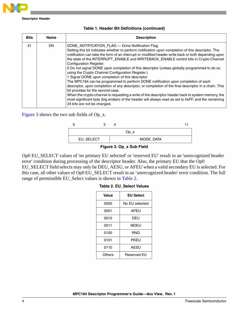
Figure 3 shows the two sub fields of Op_x.
Op0 EU_SELECT values of 'no primary EU selected' or 'reserved EU' result in an 'unrecognized header error' condition during processing of the descriptor header. Also, the primary EU that the Op0 EU_SELECT field selects may only be DEU, AESU, or AFEU when a valid secondary EU is selected. For this case, all other values of Op0 EU_SELECT result in an ‘unrecognized header' error condition. The full range of permissible EU_Select values is shown in Table 2.
31 DN DONE_NOTIFICATION_FLAG — Done Notification Flag.Setting this bit indicates whether to perform notification upon completion of this descriptor. The notification can take the form of an interrupt or modified header write back or both depending upon the state of the INTERRUPT_ENABLE and WRITEBACK_ENABLE control bits in Crypto Channel Configuration Register. 0 Do not signal DONE upon completion of this descriptor (unless globally programmed to do so using the Crypto Channel Configuration Register.)1 Signal DONE upon completion of this descriptorThe MPC184 can be programmed to perform DONE notification upon completion of each descriptor, upon completion of any descriptor, or completion of the final descriptor in a chain. This bit provides for the second case.When the crypto-channel is requesting a write of the descriptor header back to system memory, the most significant byte (big endian) of the header will always read as set to 0xFF, and the remaining 24 bits are not be changed.
0 3 4 11
Op_x
EU_SELECT MODE_DATA
Figure 3. Op_x Sub Field
Table 2. EU_Select Values
Value EU Select
0000 No EU selected
0001 AFEU
0010 DEU
0011 MDEU
0100 RNG
0101 PKEU
0110 AESU
Others Reserved EU
Table 1. Header Bit Definitions (continued)
Bits Name Description
MPC184 Descriptor Programmer’s Guide—8xx View, Rev. 1
Freescale Semiconductor 5
Execution Unit Mode Data
4 Execution Unit Mode DataThe MPC184 execution units are programmed using the descriptor header. The Mode_Data portion of Op_X field in the descriptor header is written to bits 0:7 of the mode register in the execution unit selected by the EU_Select field in Op_X. A complete explanation of the execution unit registers can be found in Chapter 4 of the MPC184 8xx Security Co-Processor User’s Manual; however, the mode register for each EU is provided in this section for convenience.
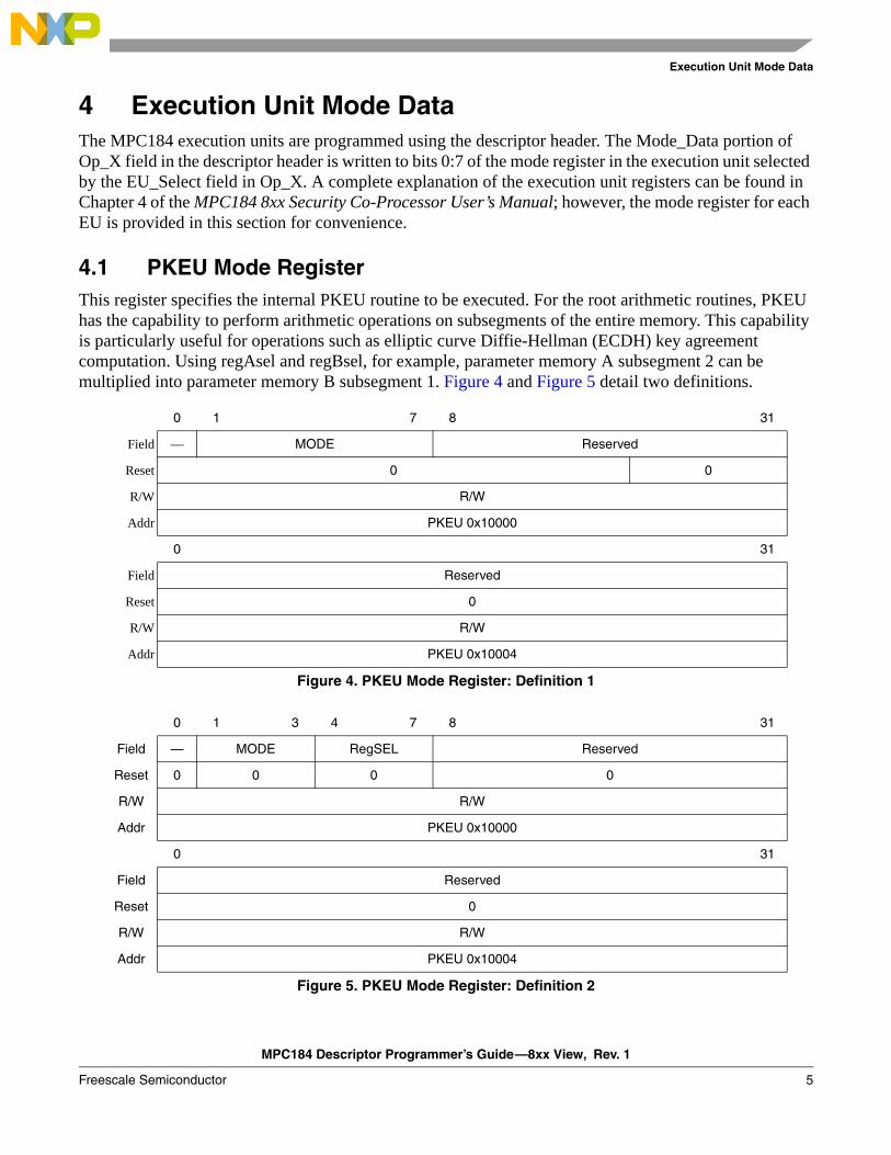
4.1 PKEU Mode RegisterThis register specifies the internal PKEU routine to be executed. For the root arithmetic routines, PKEU has the capability to perform arithmetic operations on subsegments of the entire memory. This capability is particularly useful for operations such as elliptic curve Diffie-Hellman (ECDH) key agreement computation. Using regAsel and regBsel, for example, parameter memory A subsegment 2 can be multiplied into parameter memory B subsegment 1. Figure 4 and Figure 5 detail two definitions.
0 1 7 8 31
Field — MODE Reserved
Reset 0 0
R/W R/W
Addr PKEU 0x10000
0 31
Field Reserved
Reset 0
R/W R/W
Addr PKEU 0x10004
Figure 4. PKEU Mode Register: Definition 1
0 1 3 4 7 8 31
Field — MODE RegSEL Reserved
Reset 0 0 0 0
R/W R/W
Addr PKEU 0x10000
0 31
Field Reserved
Reset 0
R/W R/W
Addr PKEU 0x10004
Figure 5. PKEU Mode Register: Definition 2
MPC184 Descriptor Programmer’s Guide—8xx View, Rev. 1
6 Freescale Semiconductor
Execution Unit Mode Data
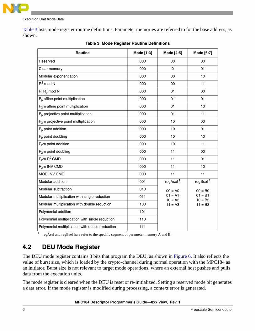
Table 3 lists mode register routine definitions. Parameter memories are referred to for the base address, as shown.
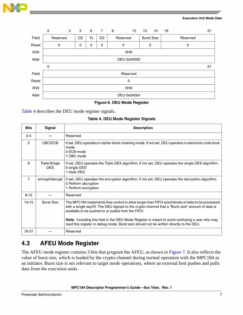
4.2 DEU Mode RegisterThe DEU mode register contains 3 bits that program the DEU, as shown in Figure 6. It also reflects the value of burst size, which is loaded by the crypto-channel during normal operation with the MPC184 as an initiator. Burst size is not relevant to target mode operations, where an external host pushes and pulls data from the execution units.
The mode register is cleared when the DEU is reset or re-initialized. Setting a reserved mode bit generates a data error. If the mode register is modified during processing, a context error is generated.
Table 3. Mode Register Routine Definitions
Routine Mode [1:3] Mode [4:5] Mode [6:7]
Reserved 000 00 00
Clear memory 000 0 01
Modular exponentiation 000 00 10
R2 mod N 000 00 11
RnRp mod N 000 01 00
Fp affine point multiplication 000 01 01
F2m affine point multiplication 000 01 10
Fp projective point multiplication 000 01 11
F2m projective point multiplication 000 10 00
Fp point addition 000 10 01
Fp point doubling 000 10 10
F2m point addition 000 10 11
F2m point doubling 000 11 00
F2m R2 CMD 000 11 01
F2m INV CMD 000 11 10
MOD INV CMD 000 11 11
Modular addition 001 regAsel 1
00 = A001 = A110 = A211 = A3
1 regAsel and regBsel here refer to the specific segment of parameter memory A and B.
regBsel 1
00 = B001 = B110 = B211 = B3
Modular subtraction 010
Modular multiplication with single reduction 011
Modular multiplication with double reduction 100
Polynomial addition 101
Polynomial multiplication with single reduction 110
Polynomial multiplication with double reduction 111
MPC184 Descriptor Programmer’s Guide—8xx View, Rev. 1
Freescale Semiconductor 7
Execution Unit Mode Data
Table 4 describes the DEU mode register signals.
4.3 AFEU Mode RegisterThe AFEU mode register contains 3 bits that program the AFEU, as shown in Figure 7. It also reflects the value of burst size, which is loaded by the crypto-channel during normal operation with the MPC184 as an initiator. Burst size is not relevant to target mode operations, where an external host pushes and pulls data from the execution units.
0 4 5 6 7 8 12 13 15 16 31
Field Reserved CE Ts ED Reserved Burst Size Reserved
Reset 0 0 0 0 0 0 0
R/W R/W
Addr DEU 0x0A000
0 31
Field Reserved
Reset 0
R/W R/W
Addr DEU 0x0A004
Figure 6. DEU Mode Register
Table 4. DEU Mode Register Signals
Bits Signal Description
0-4 — Reserved
5 CBC/ECB If set, DEU operates in cipher-block-chaining mode. If not set, DEU operates in electronic code book mode.0 ECB mode1 CBC mode
6 Triple/Single DES
If set, DEU operates the Triple DES algorithm; if not set, DEU operates the single DES algorithm. 0 single DES 1 triple DES
7 encrypt/decrypt If set, DEU operates the encryption algorithm; if not set, DEU operates the decryption algorithm.0 Perform decryption1 Perform encryption
8-12 — Reserved
13-15 Burst Size The MPC184 implements flow control to allow larger than FIFO sized blocks of data to be processed with a single key/IV. The DEU signals to the crypto-channel that a “Burst size” amount of data is available to be pushed to or pulled from the FIFO.
Note: Including this field in the DEU Mode Register is meant to avoid confusing a user who may read this register in debug mode. Burst size should not be written directly to the DEU.
16-31 — Reserved
MPC184 Descriptor Programmer’s Guide—8xx View, Rev. 1
8 Freescale Semiconductor
Execution Unit Mode Data
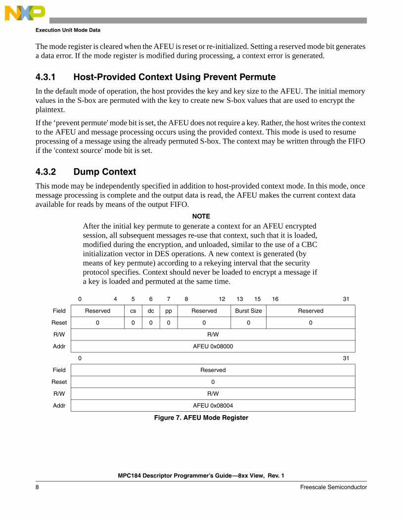
The mode register is cleared when the AFEU is reset or re-initialized. Setting a reserved mode bit generates a data error. If the mode register is modified during processing, a context error is generated.
4.3.1 Host-Provided Context Using Prevent PermuteIn the default mode of operation, the host provides the key and key size to the AFEU. The initial memory values in the S-box are permuted with the key to create new S-box values that are used to encrypt the plaintext.
If the ‘prevent permute' mode bit is set, the AFEU does not require a key. Rather, the host writes the context to the AFEU and message processing occurs using the provided context. This mode is used to resume processing of a message using the already permuted S-box. The context may be written through the FIFO if the 'context source' mode bit is set.
4.3.2 Dump ContextThis mode may be independently specified in addition to host-provided context mode. In this mode, once message processing is complete and the output data is read, the AFEU makes the current context data available for reads by means of the output FIFO.
NOTE
After the initial key permute to generate a context for an AFEU encrypted session, all subsequent messages re-use that context, such that it is loaded, modified during the encryption, and unloaded, similar to the use of a CBC initialization vector in DES operations. A new context is generated (by means of key permute) according to a rekeying interval that the security protocol specifies. Context should never be loaded to encrypt a message if a key is loaded and permuted at the same time.
0 4 5 6 7 8 12 13 15 16 31
Field Reserved cs dc pp Reserved Burst Size Reserved
Reset 0 0 0 0 0 0 0
R/W R/W
Addr AFEU 0x08000
0 31
Field Reserved
Reset 0
R/W R/W
Addr AFEU 0x08004
Figure 7. AFEU Mode Register
MPC184 Descriptor Programmer’s Guide—8xx View, Rev. 1
Freescale Semiconductor 9
Execution Unit Mode Data
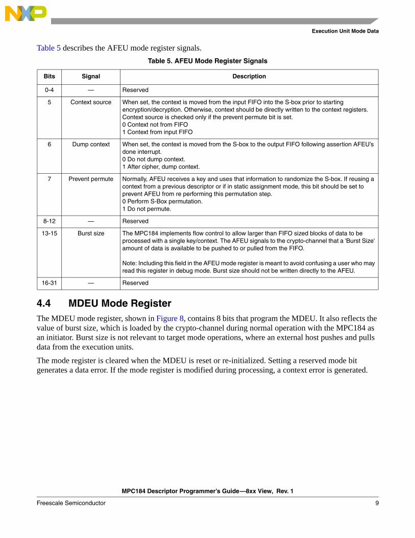
Table 5 describes the AFEU mode register signals.
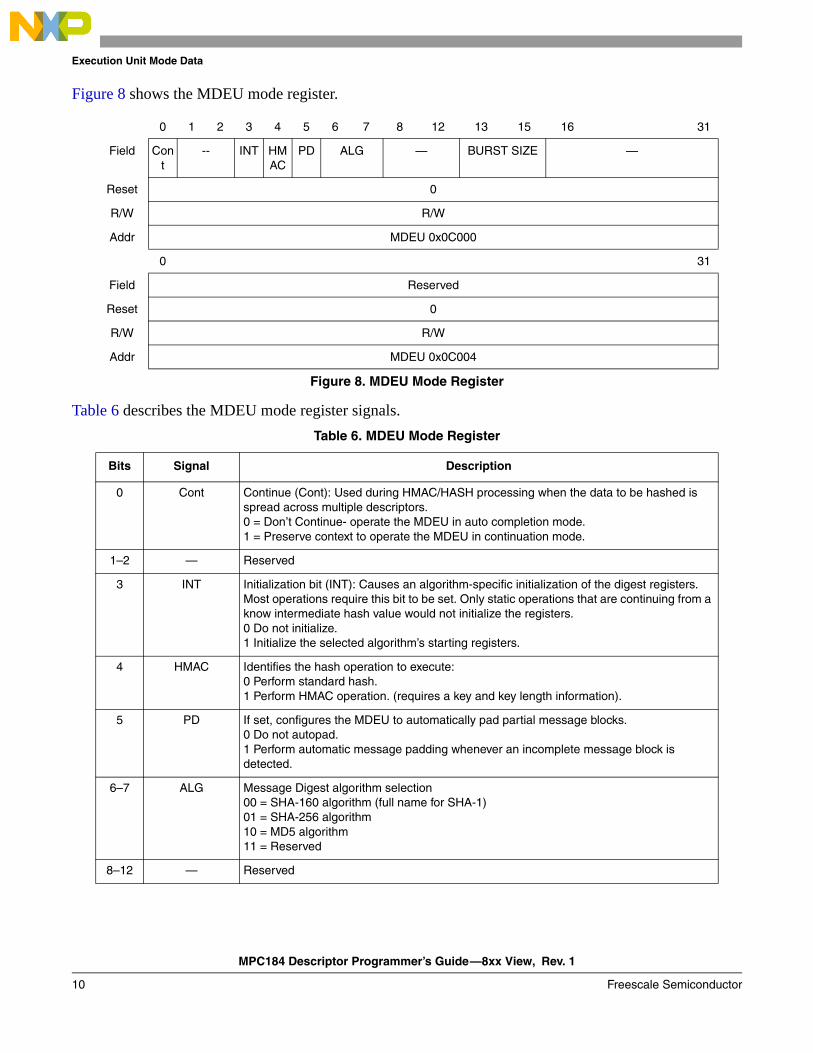
4.4 MDEU Mode RegisterThe MDEU mode register, shown in Figure 8, contains 8 bits that program the MDEU. It also reflects the value of burst size, which is loaded by the crypto-channel during normal operation with the MPC184 as an initiator. Burst size is not relevant to target mode operations, where an external host pushes and pulls data from the execution units.
The mode register is cleared when the MDEU is reset or re-initialized. Setting a reserved mode bit generates a data error. If the mode register is modified during processing, a context error is generated.
Table 5. AFEU Mode Register Signals
Bits Signal Description
0-4 — Reserved
5 Context source When set, the context is moved from the input FIFO into the S-box prior to starting encryption/decryption. Otherwise, context should be directly written to the context registers. Context source is checked only if the prevent permute bit is set.0 Context not from FIFO1 Context from input FIFO
6 Dump context When set, the context is moved from the S-box to the output FIFO following assertion AFEU’s done interrupt.0 Do not dump context.1 After cipher, dump context.
7 Prevent permute Normally, AFEU receives a key and uses that information to randomize the S-box. If reusing a context from a previous descriptor or if in static assignment mode, this bit should be set to prevent AFEU from re performing this permutation step.0 Perform S-Box permutation.1 Do not permute.
8-12 — Reserved
13-15 Burst size The MPC184 implements flow control to allow larger than FIFO sized blocks of data to be processed with a single key/context. The AFEU signals to the crypto-channel that a 'Burst Size' amount of data is available to be pushed to or pulled from the FIFO.
Note: Including this field in the AFEU mode register is meant to avoid confusing a user who may read this register in debug mode. Burst size should not be written directly to the AFEU.
16-31 — Reserved
MPC184 Descriptor Programmer’s Guide—8xx View, Rev. 1
10 Freescale Semiconductor
Execution Unit Mode Data
Figure 8 shows the MDEU mode register.
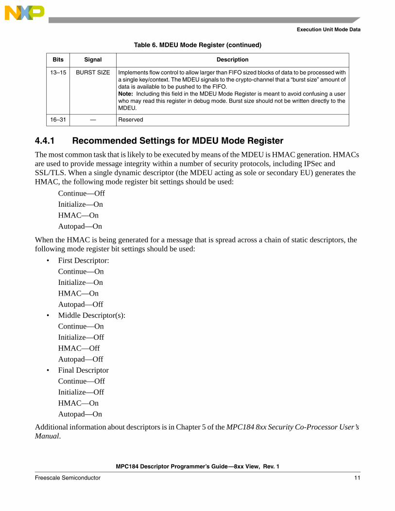
Table 6 describes the MDEU mode register signals.
0 1 2 3 4 5 6 7 8 12 13 15 16 31
Field Cont
-- INT HMAC
PD ALG — BURST SIZE —
Reset 0
R/W R/W
Addr MDEU 0x0C000
0 31
Field Reserved
Reset 0
R/W R/W
Addr MDEU 0x0C004
Figure 8. MDEU Mode Register
Table 6. MDEU Mode Register
Bits Signal Description
0 Cont Continue (Cont): Used during HMAC/HASH processing when the data to be hashed is spread across multiple descriptors.0 = Don’t Continue- operate the MDEU in auto completion mode.1 = Preserve context to operate the MDEU in continuation mode.
1–2 — Reserved
3 INT Initialization bit (INT): Causes an algorithm-specific initialization of the digest registers. Most operations require this bit to be set. Only static operations that are continuing from a know intermediate hash value would not initialize the registers.0 Do not initialize.1 Initialize the selected algorithm’s starting registers.
4 HMAC Identifies the hash operation to execute:0 Perform standard hash.1 Perform HMAC operation. (requires a key and key length information).
5 PD If set, configures the MDEU to automatically pad partial message blocks.0 Do not autopad.1 Perform automatic message padding whenever an incomplete message block is detected.
6–7 ALG Message Digest algorithm selection00 = SHA-160 algorithm (full name for SHA-1)01 = SHA-256 algorithm10 = MD5 algorithm11 = Reserved
8–12 — Reserved
MPC184 Descriptor Programmer’s Guide—8xx View, Rev. 1
Freescale Semiconductor 11
Execution Unit Mode Data
4.4.1 Recommended Settings for MDEU Mode RegisterThe most common task that is likely to be executed by means of the MDEU is HMAC generation. HMACs are used to provide message integrity within a number of security protocols, including IPSec and SSL/TLS. When a single dynamic descriptor (the MDEU acting as sole or secondary EU) generates the HMAC, the following mode register bit settings should be used:
Continue—OffInitialize—OnHMAC—OnAutopad—On
When the HMAC is being generated for a message that is spread across a chain of static descriptors, the following mode register bit settings should be used:
• First Descriptor:Continue—OnInitialize—OnHMAC—OnAutopad—Off
• Middle Descriptor(s):Continue—OnInitialize—OffHMAC—OffAutopad—Off
• Final DescriptorContinue—OffInitialize—OffHMAC—OnAutopad—On
Additional information about descriptors is in Chapter 5 of the MPC184 8xx Security Co-Processor User’s Manual.
13–15 BURST SIZE Implements flow control to allow larger than FIFO sized blocks of data to be processed with a single key/context. The MDEU signals to the crypto-channel that a “burst size” amount of data is available to be pushed to the FIFO.Note: Including this field in the MDEU Mode Register is meant to avoid confusing a user who may read this register in debug mode. Burst size should not be written directly to the MDEU.
16–31 — Reserved
Table 6. MDEU Mode Register (continued)
Bits Signal Description
MPC184 Descriptor Programmer’s Guide—8xx View, Rev. 1
12 Freescale Semiconductor
Execution Unit Mode Data
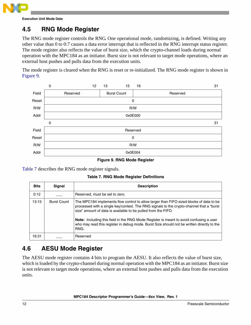
4.5 RNG Mode RegisterThe RNG mode register controls the RNG. One operational mode, randomizing, is defined. Writing any other value than 0 to 0:7 causes a data error interrupt that is reflected in the RNG interrupt status register. The mode register also reflects the value of burst size, which the crypto-channel loads during normal operation with the MPC184 as an initiator. Burst size is not relevant to target mode operations, where an external host pushes and pulls data from the execution units.
The mode register is cleared when the RNG is reset or re-initialized. The RNG mode register is shown in Figure 9.
Table 7 describes the RNG mode register signals.
4.6 AESU Mode RegisterThe AESU mode register contains 4 bits to program the AESU. It also reflects the value of burst size, which is loaded by the crypto-channel during normal operation with the MPC184 as an initiator. Burst size is not relevant to target mode operations, where an external host pushes and pulls data from the execution units.
0 12 13 15 16 31
Field Reserved Burst Count Reserved
Reset 0
R/W R/W
Addr 0x0E000
0 31
Field Reserved
Reset 0
R/W R/W
Addr 0x0E004
Figure 9. RNG Mode Register
Table 7. RNG Mode Register Definitions
Bits Signal Description
0:12 ___ Reserved, must be set to zero.
13:15 Burst Count The MPC184 implements flow control to allow larger than FIFO sized blocks of data to be processed with a single key/context. The RNG signals to the crypto-channel that a “burst size” amount of data is available to be pulled from the FIFO.
Note: Including this field in the RNG Mode Register is meant to avoid confusing a user who may read this register in debug mode. Burst Size should not be written directly to the RNG.
16:31 ___ Reserved
MPC184 Descriptor Programmer’s Guide—8xx View, Rev. 1
Freescale Semiconductor 13
Execution Unit Mode Data
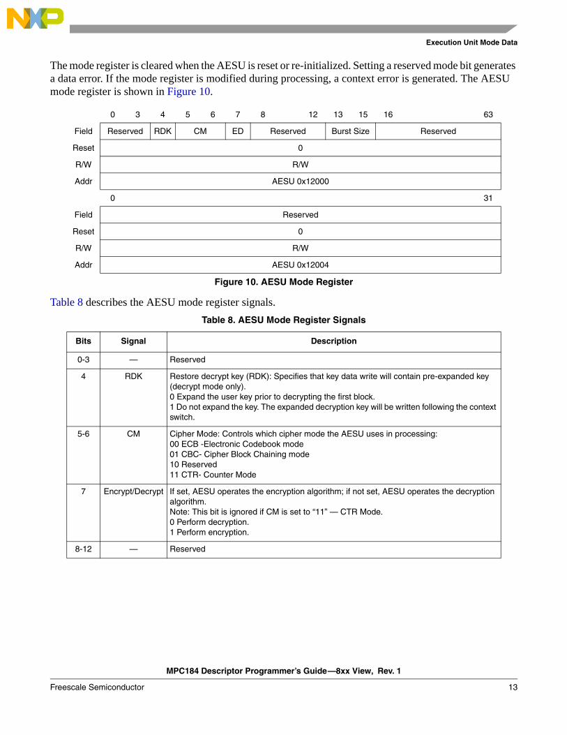
The mode register is cleared when the AESU is reset or re-initialized. Setting a reserved mode bit generates a data error. If the mode register is modified during processing, a context error is generated. The AESU mode register is shown in Figure 10.
Table 8 describes the AESU mode register signals.
0 3 4 5 6 7 8 12 13 15 16 63
Field Reserved RDK CM ED Reserved Burst Size Reserved
Reset 0
R/W R/W
Addr AESU 0x12000
0 31
Field Reserved
Reset 0
R/W R/W
Addr AESU 0x12004
Figure 10. AESU Mode Register
Table 8. AESU Mode Register Signals
Bits Signal Description
0-3 — Reserved
4 RDK Restore decrypt key (RDK): Specifies that key data write will contain pre-expanded key (decrypt mode only).0 Expand the user key prior to decrypting the first block.1 Do not expand the key. The expanded decryption key will be written following the context switch.
5-6 CM Cipher Mode: Controls which cipher mode the AESU uses in processing:00 ECB -Electronic Codebook mode01 CBC- Cipher Block Chaining mode10 Reserved11 CTR- Counter Mode
7 Encrypt/Decrypt If set, AESU operates the encryption algorithm; if not set, AESU operates the decryption algorithm.Note: This bit is ignored if CM is set to “11” — CTR Mode.0 Perform decryption.1 Perform encryption.
8-12 — Reserved
MPC184 Descriptor Programmer’s Guide—8xx View, Rev. 1
14 Freescale Semiconductor
Descriptor Type Field
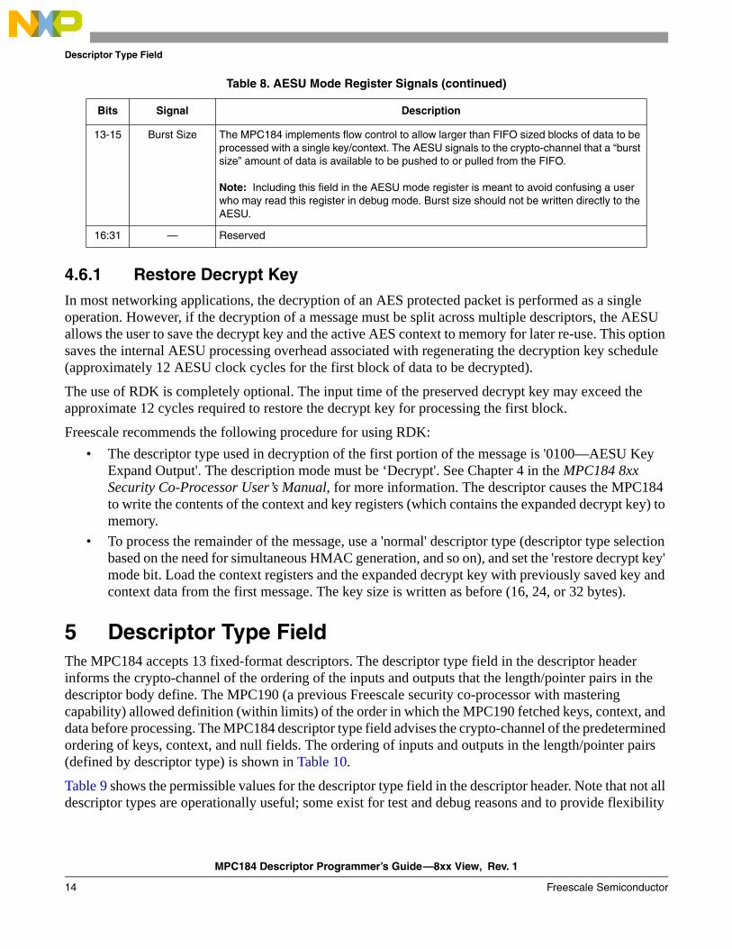
4.6.1 Restore Decrypt KeyIn most networking applications, the decryption of an AES protected packet is performed as a single operation. However, if the decryption of a message must be split across multiple descriptors, the AESU allows the user to save the decrypt key and the active AES context to memory for later re-use. This option saves the internal AESU processing overhead associated with regenerating the decryption key schedule (approximately 12 AESU clock cycles for the first block of data to be decrypted).
The use of RDK is completely optional. The input time of the preserved decrypt key may exceed the approximate 12 cycles required to restore the decrypt key for processing the first block.
Freescale recommends the following procedure for using RDK:• The descriptor type used in decryption of the first portion of the message is '0100—AESU Key
Expand Output'. The description mode must be ‘Decrypt'. See Chapter 4 in the MPC184 8xx Security Co-Processor User’s Manual, for more information. The descriptor causes the MPC184 to write the contents of the context and key registers (which contains the expanded decrypt key) to memory.
• To process the remainder of the message, use a 'normal' descriptor type (descriptor type selection based on the need for simultaneous HMAC generation, and so on), and set the 'restore decrypt key' mode bit. Load the context registers and the expanded decrypt key with previously saved key and context data from the first message. The key size is written as before (16, 24, or 32 bytes).
5 Descriptor Type FieldThe MPC184 accepts 13 fixed-format descriptors. The descriptor type field in the descriptor header informs the crypto-channel of the ordering of the inputs and outputs that the length/pointer pairs in the descriptor body define. The MPC190 (a previous Freescale security co-processor with mastering capability) allowed definition (within limits) of the order in which the MPC190 fetched keys, context, and data before processing. The MPC184 descriptor type field advises the crypto-channel of the predetermined ordering of keys, context, and null fields. The ordering of inputs and outputs in the length/pointer pairs (defined by descriptor type) is shown in Table 10.
Table 9 shows the permissible values for the descriptor type field in the descriptor header. Note that not all descriptor types are operationally useful; some exist for test and debug reasons and to provide flexibility
13-15 Burst Size The MPC184 implements flow control to allow larger than FIFO sized blocks of data to be processed with a single key/context. The AESU signals to the crypto-channel that a “burst size” amount of data is available to be pushed to or pulled from the FIFO.
Note: Including this field in the AESU mode register is meant to avoid confusing a user who may read this register in debug mode. Burst size should not be written directly to the AESU.
16:31 — Reserved
Table 8. AESU Mode Register Signals (continued)
Bits Signal Description
MPC184 Descriptor Programmer’s Guide—8xx View, Rev. 1
Freescale Semiconductor 15
Descriptor Type Field
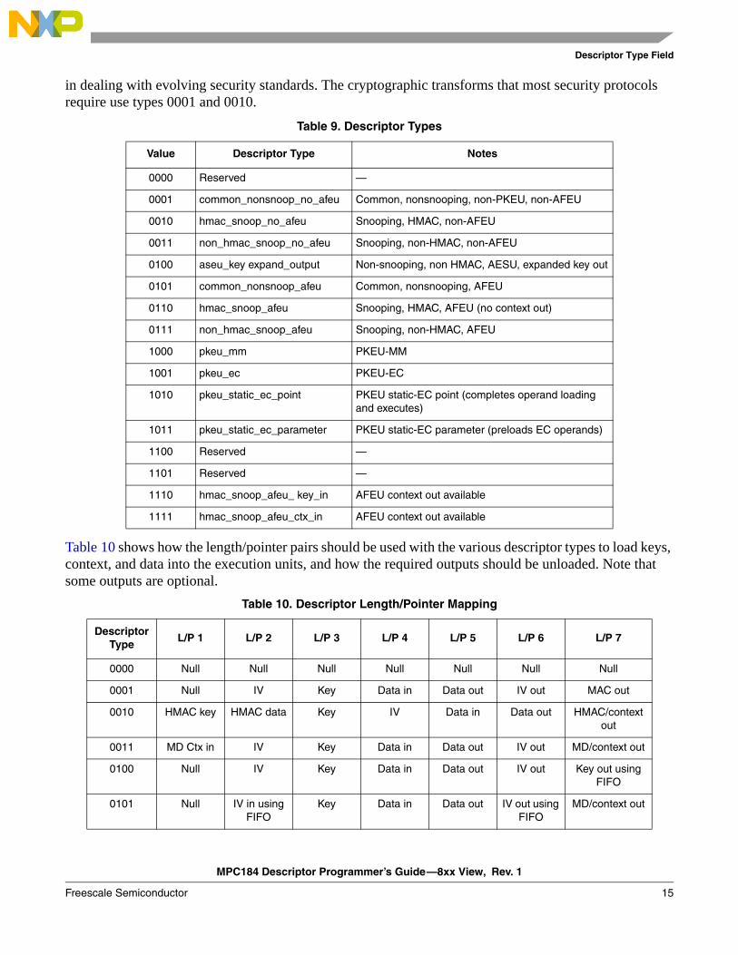
in dealing with evolving security standards. The cryptographic transforms that most security protocols require use types 0001 and 0010.
Table 10 shows how the length/pointer pairs should be used with the various descriptor types to load keys, context, and data into the execution units, and how the required outputs should be unloaded. Note that some outputs are optional.
Table 9. Descriptor Types
Value Descriptor Type Notes
0000 Reserved —
0001 common_nonsnoop_no_afeu Common, nonsnooping, non-PKEU, non-AFEU
0010 hmac_snoop_no_afeu Snooping, HMAC, non-AFEU
0011 non_hmac_snoop_no_afeu Snooping, non-HMAC, non-AFEU
0100 aseu_key expand_output Non-snooping, non HMAC, AESU, expanded key out
0101 common_nonsnoop_afeu Common, nonsnooping, AFEU
0110 hmac_snoop_afeu Snooping, HMAC, AFEU (no context out)
0111 non_hmac_snoop_afeu Snooping, non-HMAC, AFEU
1000 pkeu_mm PKEU-MM
1001 pkeu_ec PKEU-EC
1010 pkeu_static_ec_point PKEU static-EC point (completes operand loading and executes)
1011 pkeu_static_ec_parameter PKEU static-EC parameter (preloads EC operands)
1100 Reserved —
1101 Reserved —
1110 hmac_snoop_afeu_ key_in AFEU context out available
1111 hmac_snoop_afeu_ctx_in AFEU context out available
Table 10. Descriptor Length/Pointer Mapping
Descriptor Type
L/P 1 L/P 2 L/P 3 L/P 4 L/P 5 L/P 6 L/P 7
0000 Null Null Null Null Null Null Null
0001 Null IV Key Data in Data out IV out MAC out
0010 HMAC key HMAC data Key IV Data in Data out HMAC/context out
0011 MD Ctx in IV Key Data in Data out IV out MD/context out
0100 Null IV Key Data in Data out IV out Key out using FIFO
0101 Null IV in using FIFO
Key Data in Data out IV out using FIFO
MD/context out
MPC184 Descriptor Programmer’s Guide—8xx View, Rev. 1
16 Freescale Semiconductor
Descriptor Type Field
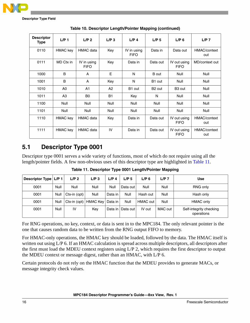
5.1 Descriptor Type 0001Descriptor type 0001 serves a wide variety of functions, most of which do not require using all the length/pointer fields. A few non-obvious uses of this descriptor type are highlighted in Table 11.
For RNG operations, no key, context, or data is sent in to the MPC184. The only relevant pointer is the one that causes random data to be written from the RNG output FIFO to memory.
For HMAC-only operations, the HMAC key should be loaded, followed by the data. The HMAC itself is written out using L/P 6. If an HMAC calculation is spread across multiple descriptors, all descriptors after the first must load the MDEU context registers using L/P 2, which requires the first descriptor to output the MDEU context or message digest, rather than an HMAC, with L/P 6.
Certain protocols do not rely on the HMAC function that the MDEU provides to generate MACs, or message integrity check values.
0110 HMAC key HMAC data Key IV in using FIFO
Data in Data out HMAC/context out
0111 MD Ctx in IV in using FIFO
Key Data in Data out IV out using FIFO
MD/context out
1000 B A E N B out Null Null
1001 B A Key N B1 out Null Null
1010 A0 A1 A2 B1 out B2 out B3 out Null
1011 A3 B0 B1 Key N Null Null
1100 Null Null Null Null Null Null Null
1101 Null Null Null Null Null Null Null
1110 HMAC key HMAC data Key Data in Data out IV out using FIFO
HMAC/context out
1111 HMAC key HMAC data IV Data in Data out IV out using FIFO
HMAC/context out
Table 11. Descriptor Type 0001 Length/Pointer Mapping
Descriptor Type L/P 1 L/P 2 L/P 3 L/P 4 L/P 5 L/P 6 L/P 7 Use
0001 Null Null Null Null Data out Null Null RNG only
0001 Null Ctx-in (opt) Null Data in Null Hash out Null Hash only
0001 Null Ctx-in (opt) HMAC Key Data in Null HMAC out Null HMAC only
0001 Null IV Key Data in Data out IV out MAC out Self-integrity checking operations
Table 10. Descriptor Length/Pointer Mapping (continued)
Descriptor Type
L/P 1 L/P 2 L/P 3 L/P 4 L/P 5 L/P 6 L/P 7
MPC184 Descriptor Programmer’s Guide—8xx View, Rev. 1
Freescale Semiconductor 17
Descriptor Type Field
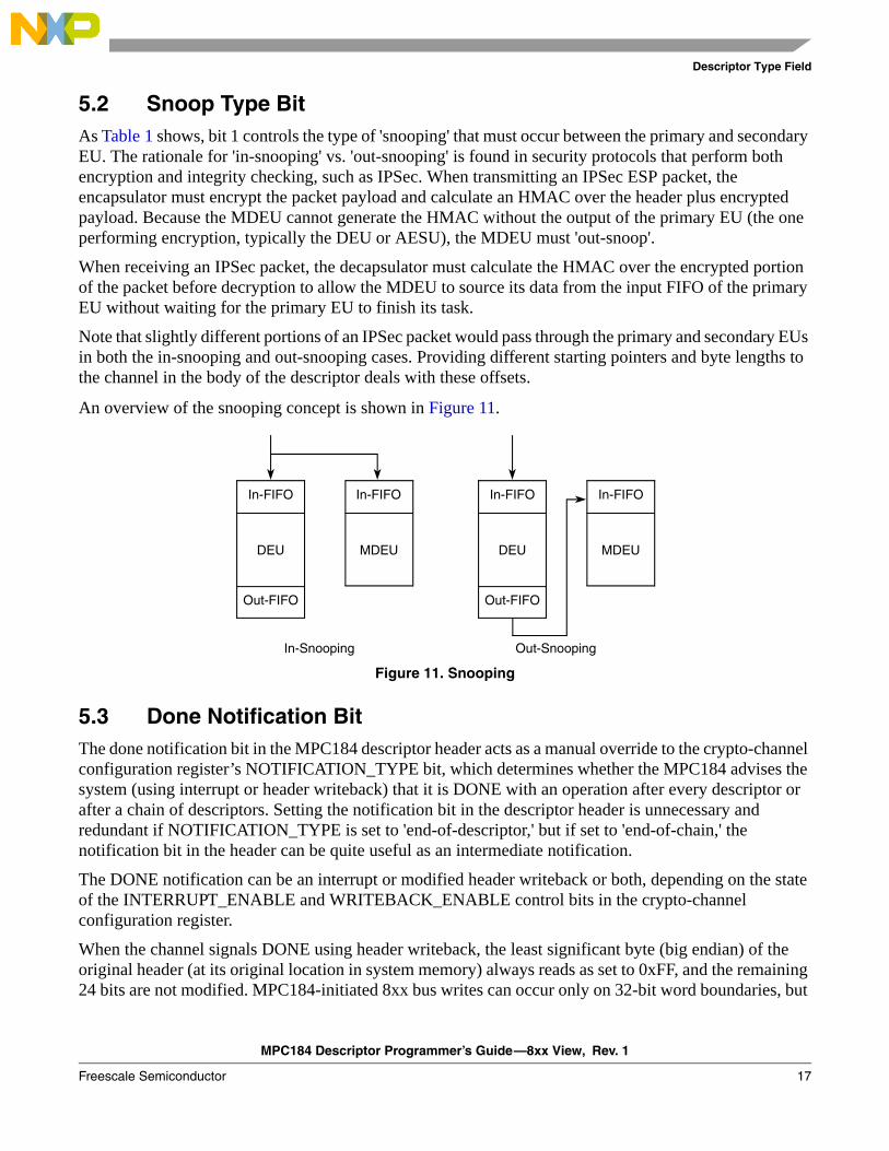
5.2 Snoop Type BitAs Table 1 shows, bit 1 controls the type of 'snooping' that must occur between the primary and secondary EU. The rationale for 'in-snooping' vs. 'out-snooping' is found in security protocols that perform both encryption and integrity checking, such as IPSec. When transmitting an IPSec ESP packet, the encapsulator must encrypt the packet payload and calculate an HMAC over the header plus encrypted payload. Because the MDEU cannot generate the HMAC without the output of the primary EU (the one performing encryption, typically the DEU or AESU), the MDEU must 'out-snoop'.
When receiving an IPSec packet, the decapsulator must calculate the HMAC over the encrypted portion of the packet before decryption to allow the MDEU to source its data from the input FIFO of the primary EU without waiting for the primary EU to finish its task.
Note that slightly different portions of an IPSec packet would pass through the primary and secondary EUs in both the in-snooping and out-snooping cases. Providing different starting pointers and byte lengths to the channel in the body of the descriptor deals with these offsets.
An overview of the snooping concept is shown in Figure 11.
Figure 11. Snooping
5.3 Done Notification BitThe done notification bit in the MPC184 descriptor header acts as a manual override to the crypto-channel configuration register’s NOTIFICATION_TYPE bit, which determines whether the MPC184 advises the system (using interrupt or header writeback) that it is DONE with an operation after every descriptor or after a chain of descriptors. Setting the notification bit in the descriptor header is unnecessary and redundant if NOTIFICATION_TYPE is set to 'end-of-descriptor,' but if set to 'end-of-chain,' the notification bit in the header can be quite useful as an intermediate notification.
The DONE notification can be an interrupt or modified header writeback or both, depending on the state of the INTERRUPT_ENABLE and WRITEBACK_ENABLE control bits in the crypto-channel configuration register.
When the channel signals DONE using header writeback, the least significant byte (big endian) of the original header (at its original location in system memory) always reads as set to 0xFF, and the remaining 24 bits are not modified. MPC184-initiated 8xx bus writes can occur only on 32-bit word boundaries, but
In-Snooping Out-Snooping
In-FIFO
DEU
Out-FIFO
MDEU
In-FIFO In-FIFO
Out-FIFO
In-FIFO
MDEUDEU

MPC184 Descriptor Programmer’s Guide—8xx View, Rev. 1
18 Freescale Semiconductor
Descriptor Length and Pointer Fields
reads can occur on any byte boundary. Writing back a header read from a non-32-bit word boundary yields unpredictable results.
6 Descriptor Length and Pointer FieldsThe length and pointer fields represent one of seven data length/pointer pairs. Each pair defines a block of data in system memory. The length field gives the length of the block in bytes. The maximum allowable number of bytes is 32 Kbytes. A value of 0 loaded into the length field indicates that this length/pointer pair should be skipped, and processing should continue with the next pair.
The pointer field contains the address, in 8xx address space, of the first byte of the data block. Transfers from the 8xx bus with the pointer address set to 0 have the length value written to the EU, and no data is fetched from the 8xx bus.
NOTE
Certain public key operations require information about data length, but not the data itself. Figure 12 shows the descriptor length field.
Table 12 shows the descriptor length field mapping.
0 15 16 31
Field Reserved Data Length Field
0 msb<--------lsb
Reset 0
R/W R/W
Figure 12. Descriptor Length Field
Table 12. Descriptor Length Field Mapping
Bits Name Reset Value Description
0:15 — 0 Reserved, set to zero
16:31 Data Field Length
0 The maximum length this field can be set to 32K bytes. Under host control, a channel can be temporarily locked static, and data only” descriptors can be chained to fetch blocks larger than 32K bytes in 32K byte sub-blocks without key/context switching, until the large original block has been completely ciphered. Length fields also indicate the size of items to be written back to memory upon completion of security processing in the MPC184.

MPC184 Descriptor Programmer’s Guide—8xx View, Rev. 1
Freescale Semiconductor 19
Descriptor Length and Pointer Fields
Figure 13 shows the descriptor pointer field.
Table 13 shows the descriptor pointer field mapping.
Following the length/pointer pairs is the next descriptor field, which contains the pointer to the next descriptor in memory. When processing of the current descriptor completes, this value, if non-zero, is used to request an 8xx burst read of the next data packet descriptor. This automatic load of the next descriptor is called descriptor chaining. Figure 14 displays the next descriptor pointer field.
Table 14 describes the descriptor pointer field mapping.
0 31
Field Data Field X Pointer
Reset 0
R/W R/W
Figure 13. Descriptor Pointer Field
Table 13. Descriptor Pointer Field Mapping
Bits Name Reset Value Description
0:31 Data field pointer 0 The data pointer field contains the address, in 8xx address space, of the first byte of the data packet for either read or writeback. Transfers from the 8xx bus with pointer address set to zero will be skipped.
WARNINGMPC184-initiated 8xx bus writes can occur only on 32-bit word boundaries, but reads can occur on any byte boundary. Writing back a header read from a non-32-bit word boundary will yield unpredictable results.
0 31
Field Next Descriptor Pointer
Reset 0
R/W R/W
Figure 14. Next Descriptor Pointer Field
Table 14. Descriptor Pointer Field Mapping
Bits Name Reset Value Description
0:31 Next descriptor pointer
0 The next descriptor pointer field contains the address, in 8xx address space, of the next descriptor to be fetched if descriptor chaining is enabled.
WARNINGThe next descriptor pointer address must be modulo-4aligned if writeback is enabled as the method of DONE notification.
MPC184 Descriptor Programmer’s Guide—8xx View, Rev. 1
20 Freescale Semiconductor
Descriptor Chaining
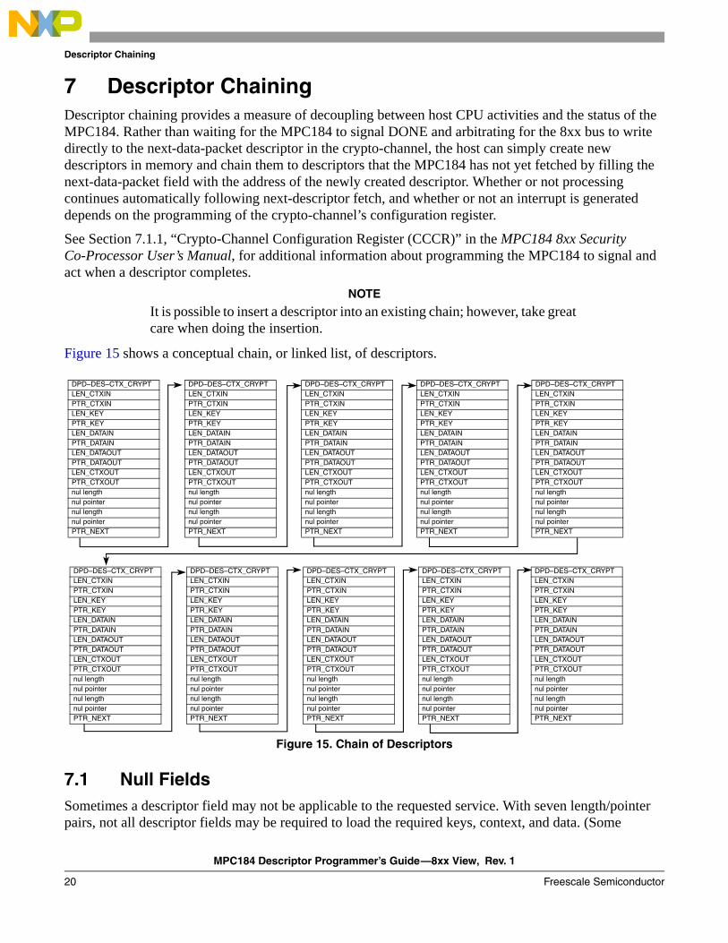
7 Descriptor ChainingDescriptor chaining provides a measure of decoupling between host CPU activities and the status of the MPC184. Rather than waiting for the MPC184 to signal DONE and arbitrating for the 8xx bus to write directly to the next-data-packet descriptor in the crypto-channel, the host can simply create new descriptors in memory and chain them to descriptors that the MPC184 has not yet fetched by filling the next-data-packet field with the address of the newly created descriptor. Whether or not processing continues automatically following next-descriptor fetch, and whether or not an interrupt is generated depends on the programming of the crypto-channel’s configuration register.
See Section 7.1.1, “Crypto-Channel Configuration Register (CCCR)” in the MPC184 8xx Security Co-Processor User’s Manual, for additional information about programming the MPC184 to signal and act when a descriptor completes.
NOTE
It is possible to insert a descriptor into an existing chain; however, take great care when doing the insertion.
Figure 15 shows a conceptual chain, or linked list, of descriptors.
Figure 15. Chain of Descriptors
7.1 Null FieldsSometimes a descriptor field may not be applicable to the requested service. With seven length/pointer pairs, not all descriptor fields may be required to load the required keys, context, and data. (Some
DPD–DES–CTX_CRYPTLEN_CTXINPTR_CTXINLEN_KEYPTR_KEYLEN_DATAINPTR_DATAINLEN_DATAOUTPTR_DATAOUTLEN_CTXOUTPTR_CTXOUTnul lengthnul pointernul lengthnul pointerPTR_NEXT
DPD–DES–CTX_CRYPTLEN_CTXINPTR_CTXINLEN_KEYPTR_KEYLEN_DATAINPTR_DATAINLEN_DATAOUTPTR_DATAOUTLEN_CTXOUTPTR_CTXOUTnul lengthnul pointernul lengthnul pointerPTR_NEXT
DPD–DES–CTX_CRYPTLEN_CTXINPTR_CTXINLEN_KEYPTR_KEYLEN_DATAINPTR_DATAINLEN_DATAOUTPTR_DATAOUTLEN_CTXOUTPTR_CTXOUTnul lengthnul pointernul lengthnul pointerPTR_NEXT
DPD–DES–CTX_CRYPTLEN_CTXINPTR_CTXINLEN_KEYPTR_KEYLEN_DATAINPTR_DATAINLEN_DATAOUTPTR_DATAOUTLEN_CTXOUTPTR_CTXOUTnul lengthnul pointernul lengthnul pointerPTR_NEXT
DPD–DES–CTX_CRYPTLEN_CTXINPTR_CTXINLEN_KEYPTR_KEYLEN_DATAINPTR_DATAINLEN_DATAOUTPTR_DATAOUTLEN_CTXOUTPTR_CTXOUTnul lengthnul pointernul lengthnul pointerPTR_NEXT
DPD–DES–CTX_CRYPTLEN_CTXINPTR_CTXINLEN_KEYPTR_KEYLEN_DATAINPTR_DATAINLEN_DATAOUTPTR_DATAOUTLEN_CTXOUTPTR_CTXOUTnul lengthnul pointernul lengthnul pointerPTR_NEXT
DPD–DES–CTX_CRYPTLEN_CTXINPTR_CTXINLEN_KEYPTR_KEYLEN_DATAINPTR_DATAINLEN_DATAOUTPTR_DATAOUTLEN_CTXOUTPTR_CTXOUTnul lengthnul pointernul lengthnul pointerPTR_NEXT
DPD–DES–CTX_CRYPTLEN_CTXINPTR_CTXINLEN_KEYPTR_KEYLEN_DATAINPTR_DATAINLEN_DATAOUTPTR_DATAOUTLEN_CTXOUTPTR_CTXOUTnul lengthnul pointernul lengthnul pointerPTR_NEXT
DPD–DES–CTX_CRYPTLEN_CTXINPTR_CTXINLEN_KEYPTR_KEYLEN_DATAINPTR_DATAINLEN_DATAOUTPTR_DATAOUTLEN_CTXOUTPTR_CTXOUTnul lengthnul pointernul lengthnul pointerPTR_NEXT
DPD–DES–CTX_CRYPTLEN_CTXINPTR_CTXINLEN_KEYPTR_KEYLEN_DATAINPTR_DATAINLEN_DATAOUTPTR_DATAOUTLEN_CTXOUTPTR_CTXOUTnul lengthnul pointernul lengthnul pointerPTR_NEXT
MPC184 Descriptor Programmer’s Guide—8xx View, Rev. 1
Freescale Semiconductor 21
Descriptor Classes
operations do not require context, and others may need only to fetch a small, contiguous block of data.) When processing data packet descriptors, the MPC184 entirely skips any pointer that has an associated length of 0.
8 Descriptor ClassesThe MPC184 has two general classes of descriptors:
• Static—a relatively unchanging usage of MPC184 resources• Dynamic—a continually changing usage model
8.1 Static DescriptorsRecall that the MPC184 has six execution units and four crypto-channels. The EUs can be statically assigned, dedicating them to a particular crypto-channel. Certain combinations of EUs can be statically assigned to the same crypto-channel to facilitate multi-operation security processes, such as IPSec ESP mode. When the system traffic model permits its use, static assignment can offer significant performance improvements over dynamic assignment by avoiding key and context switching per packet.
Static descriptors split the operations to be performed during a security operation into separate descriptors. The first descriptor is typically used only to set the EU mode and load the key and context. The second (and multiple subsequent) descriptor contains length/pointer pairs to the data to be permuted. Because the key and context are unchanging over multiple packets (or descriptors), the series of short reads and writes required to setup and tear down a session are avoided. This savings, along with the crypto-channel’s dedicated execution units, can provide a noticeable performance improvement.
Note that no mechanism exists to reset an EU automatically when statically assigned or when assignment changes from static to dynamic. Therefore, Freescale recommends that the drivers always reset an EU just before removing a static assignment to it to prevent the previously used context from polluting another encryption stream.
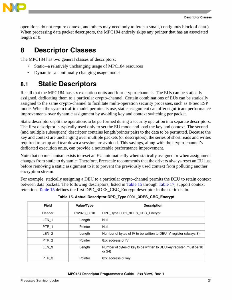
For example, statically assigning a DEU to a particular crypto-channel permits the DEU to retain context between data packets. The following descriptors, listed in Table 15 through Table 17, support context retention. Table 15 defines the first DPD_3DES_CBC_Encrypt descriptor in the static chain.
Table 15. Actual Descriptor DPD_Type 0001_3DES_CBC_Encrypt
Field Value/Type Description
Header 0x2070_0010 DPD_Type 0001_3DES_CBC_Encrypt
LEN_1 Length Null
PTR_1 Pointer Null
LEN_2 Length Number of bytes of IV to be written to DEU IV register (always 8)
PTR_2 Pointer 8xx address of IV
LEN_3 Length Number of bytes of key to be written to DEU key register (must be 16 or 24)
PTR_3 Pointer 8xx address of key
MPC184 Descriptor Programmer’s Guide—8xx View, Rev. 1
22 Freescale Semiconductor
Descriptor Classes
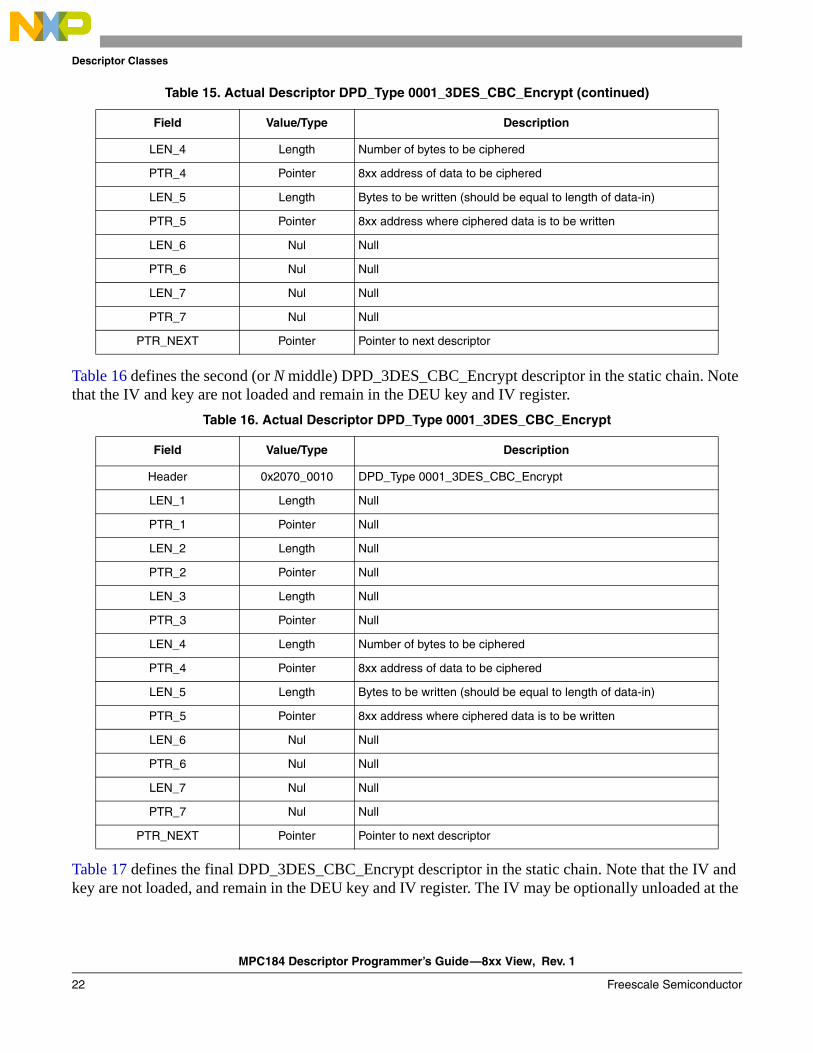
Table 16 defines the second (or N middle) DPD_3DES_CBC_Encrypt descriptor in the static chain. Note that the IV and key are not loaded and remain in the DEU key and IV register.
Table 17 defines the final DPD_3DES_CBC_Encrypt descriptor in the static chain. Note that the IV and key are not loaded, and remain in the DEU key and IV register. The IV may be optionally unloaded at the
LEN_4 Length Number of bytes to be ciphered
PTR_4 Pointer 8xx address of data to be ciphered
LEN_5 Length Bytes to be written (should be equal to length of data-in)
PTR_5 Pointer 8xx address where ciphered data is to be written
LEN_6 Nul Null
PTR_6 Nul Null
LEN_7 Nul Null
PTR_7 Nul Null
PTR_NEXT Pointer Pointer to next descriptor
Table 16. Actual Descriptor DPD_Type 0001_3DES_CBC_Encrypt
Field Value/Type Description
Header 0x2070_0010 DPD_Type 0001_3DES_CBC_Encrypt
LEN_1 Length Null
PTR_1 Pointer Null
LEN_2 Length Null
PTR_2 Pointer Null
LEN_3 Length Null
PTR_3 Pointer Null
LEN_4 Length Number of bytes to be ciphered
PTR_4 Pointer 8xx address of data to be ciphered
LEN_5 Length Bytes to be written (should be equal to length of data-in)
PTR_5 Pointer 8xx address where ciphered data is to be written
LEN_6 Nul Null
PTR_6 Nul Null
LEN_7 Nul Null
PTR_7 Nul Null
PTR_NEXT Pointer Pointer to next descriptor
Table 15. Actual Descriptor DPD_Type 0001_3DES_CBC_Encrypt (continued)
Field Value/Type Description
MPC184 Descriptor Programmer’s Guide—8xx View, Rev. 1
Freescale Semiconductor 23
Descriptor Classes
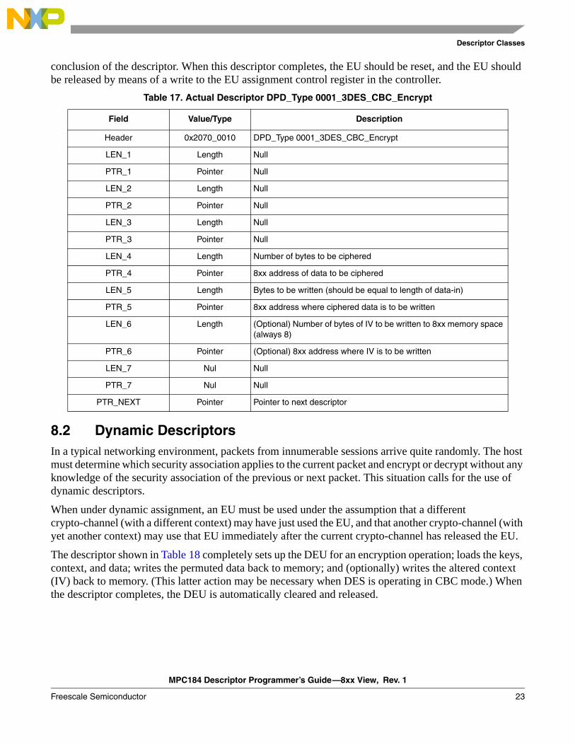
conclusion of the descriptor. When this descriptor completes, the EU should be reset, and the EU should be released by means of a write to the EU assignment control register in the controller.
8.2 Dynamic DescriptorsIn a typical networking environment, packets from innumerable sessions arrive quite randomly. The host must determine which security association applies to the current packet and encrypt or decrypt without any knowledge of the security association of the previous or next packet. This situation calls for the use of dynamic descriptors.
When under dynamic assignment, an EU must be used under the assumption that a different crypto-channel (with a different context) may have just used the EU, and that another crypto-channel (with yet another context) may use that EU immediately after the current crypto-channel has released the EU.
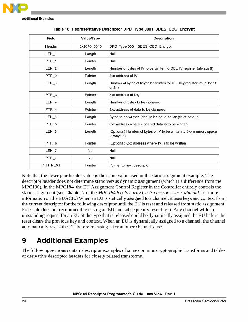
The descriptor shown in Table 18 completely sets up the DEU for an encryption operation; loads the keys, context, and data; writes the permuted data back to memory; and (optionally) writes the altered context (IV) back to memory. (This latter action may be necessary when DES is operating in CBC mode.) When the descriptor completes, the DEU is automatically cleared and released.
Table 17. Actual Descriptor DPD_Type 0001_3DES_CBC_Encrypt
Field Value/Type Description
Header 0x2070_0010 DPD_Type 0001_3DES_CBC_Encrypt
LEN_1 Length Null
PTR_1 Pointer Null
LEN_2 Length Null
PTR_2 Pointer Null
LEN_3 Length Null
PTR_3 Pointer Null
LEN_4 Length Number of bytes to be ciphered
PTR_4 Pointer 8xx address of data to be ciphered
LEN_5 Length Bytes to be written (should be equal to length of data-in)
PTR_5 Pointer 8xx address where ciphered data is to be written
LEN_6 Length (Optional) Number of bytes of IV to be written to 8xx memory space (always 8)
PTR_6 Pointer (Optional) 8xx address where IV is to be written
LEN_7 Nul Null
PTR_7 Nul Null
PTR_NEXT Pointer Pointer to next descriptor
MPC184 Descriptor Programmer’s Guide—8xx View, Rev. 1
24 Freescale Semiconductor
Additional Examples
Note that the descriptor header value is the same value used in the static assignment example. The descriptor header does not determine static versus dynamic assignment (which is a difference from the MPC190). In the MPC184, the EU Assignment Control Register in the Controller entirely controls the static assignment (see Chapter 7 in the MPC184 8xx Security Co-Processor User’s Manual, for more information on the EUACR.) When an EU is statically assigned to a channel, it uses keys and context from the current descriptor for the following descriptor until the EU is reset and released from static assignment. Freescale does not recommend releasing an EU and subsequently resetting it. Any channel with an outstanding request for an EU of the type that is released could be dynamically assigned the EU before the reset clears the previous key and context. When an EU is dynamically assigned to a channel, the channel automatically resets the EU before releasing it for another channel’s use.
9 Additional ExamplesThe following sections contain descriptor examples of some common cryptographic transforms and tables of derivative descriptor headers for closely related transforms.
Table 18. Representative Descriptor DPD_Type 0001_3DES_CBC_Encrypt
Field Value/Type Description
Header 0x2070_0010 DPD_Type 0001_3DES_CBC_Encrypt
LEN_1 Length Null
PTR_1 Pointer Null
LEN_2 Length Number of bytes of IV to be written to DEU IV register (always 8)
PTR_2 Pointer 8xx address of IV
LEN_3 Length Number of bytes of key to be written to DEU key register (must be 16 or 24)
PTR_3 Pointer 8xx address of key
LEN_4 Length Number of bytes to be ciphered
PTR_4 Pointer 8xx address of data to be ciphered
LEN_5 Length Bytes to be written (should be equal to length of data-in)
PTR_5 Pointer 8xx address where ciphered data is to be written
LEN_6 Length (Optional) Number of bytes of IV to be written to 8xx memory space (always 8)
PTR_6 Pointer (Optional) 8xx address where IV is to be written
LEN_7 Nul Null
PTR_7 Nul Null
PTR_NEXT Pointer Pointer to next descriptor
MPC184 Descriptor Programmer’s Guide—8xx View, Rev. 1
Freescale Semiconductor 25
Additional Examples
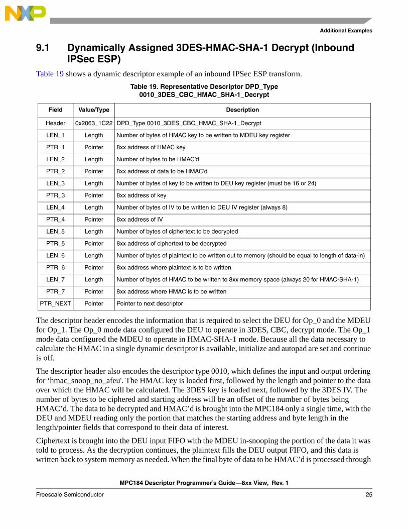
9.1 Dynamically Assigned 3DES-HMAC-SHA-1 Decrypt (Inbound IPSec ESP)
Table 19 shows a dynamic descriptor example of an inbound IPSec ESP transform.
The descriptor header encodes the information that is required to select the DEU for Op_0 and the MDEU for Op_1. The Op_0 mode data configured the DEU to operate in 3DES, CBC, decrypt mode. The Op_1 mode data configured the MDEU to operate in HMAC-SHA-1 mode. Because all the data necessary to calculate the HMAC in a single dynamic descriptor is available, initialize and autopad are set and continue is off.
The descriptor header also encodes the descriptor type 0010, which defines the input and output ordering for ‘hmac_snoop_no_afeu'. The HMAC key is loaded first, followed by the length and pointer to the data over which the HMAC will be calculated. The 3DES key is loaded next, followed by the 3DES IV. The number of bytes to be ciphered and starting address will be an offset of the number of bytes being HMAC’d. The data to be decrypted and HMAC’d is brought into the MPC184 only a single time, with the DEU and MDEU reading only the portion that matches the starting address and byte length in the length/pointer fields that correspond to their data of interest.
Ciphertext is brought into the DEU input FIFO with the MDEU in-snooping the portion of the data it was told to process. As the decryption continues, the plaintext fills the DEU output FIFO, and this data is written back to system memory as needed. When the final byte of data to be HMAC’d is processed through
Table 19. Representative Descriptor DPD_Type 0010_3DES_CBC_HMAC_SHA-1_Decrypt
Field Value/Type Description
Header 0x2063_1C22 DPD_Type 0010_3DES_CBC_HMAC_SHA-1_Decrypt
LEN_1 Length Number of bytes of HMAC key to be written to MDEU key register
PTR_1 Pointer 8xx address of HMAC key
LEN_2 Length Number of bytes to be HMAC’d
PTR_2 Pointer 8xx address of data to be HMAC’d
LEN_3 Length Number of bytes of key to be written to DEU key register (must be 16 or 24)
PTR_3 Pointer 8xx address of key
LEN_4 Length Number of bytes of IV to be written to DEU IV register (always 8)
PTR_4 Pointer 8xx address of IV
LEN_5 Length Number of bytes of ciphertext to be decrypted
PTR_5 Pointer 8xx address of ciphertext to be decrypted
LEN_6 Length Number of bytes of plaintext to be written out to memory (should be equal to length of data-in)
PTR_6 Pointer 8xx address where plaintext is to be written
LEN_7 Length Number of bytes of HMAC to be written to 8xx memory space (always 20 for HMAC-SHA-1)
PTR_7 Pointer 8xx address where HMAC is to be written
PTR_NEXT Pointer Pointer to next descriptor
MPC184 Descriptor Programmer’s Guide—8xx View, Rev. 1
26 Freescale Semiconductor
Additional Examples
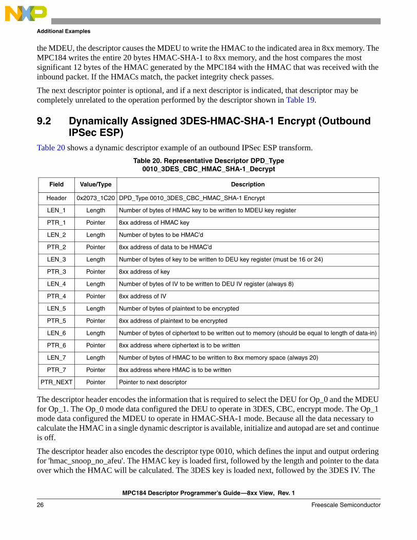
the MDEU, the descriptor causes the MDEU to write the HMAC to the indicated area in 8xx memory. The MPC184 writes the entire 20 bytes HMAC-SHA-1 to 8xx memory, and the host compares the most significant 12 bytes of the HMAC generated by the MPC184 with the HMAC that was received with the inbound packet. If the HMACs match, the packet integrity check passes.
The next descriptor pointer is optional, and if a next descriptor is indicated, that descriptor may be completely unrelated to the operation performed by the descriptor shown in Table 19.
9.2 Dynamically Assigned 3DES-HMAC-SHA-1 Encrypt (Outbound IPSec ESP)
Table 20 shows a dynamic descriptor example of an outbound IPSec ESP transform.
The descriptor header encodes the information that is required to select the DEU for Op_0 and the MDEU for Op_1. The Op_0 mode data configured the DEU to operate in 3DES, CBC, encrypt mode. The Op_1 mode data configured the MDEU to operate in HMAC-SHA-1 mode. Because all the data necessary to calculate the HMAC in a single dynamic descriptor is available, initialize and autopad are set and continue is off.
The descriptor header also encodes the descriptor type 0010, which defines the input and output ordering for 'hmac_snoop_no_afeu'. The HMAC key is loaded first, followed by the length and pointer to the data over which the HMAC will be calculated. The 3DES key is loaded next, followed by the 3DES IV. The
Table 20. Representative Descriptor DPD_Type 0010_3DES_CBC_HMAC_SHA-1_Decrypt
Field Value/Type Description
Header 0x2073_1C20 DPD_Type 0010_3DES_CBC_HMAC_SHA-1 Encrypt
LEN_1 Length Number of bytes of HMAC key to be written to MDEU key register
PTR_1 Pointer 8xx address of HMAC key
LEN_2 Length Number of bytes to be HMAC’d
PTR_2 Pointer 8xx address of data to be HMAC’d
LEN_3 Length Number of bytes of key to be written to DEU key register (must be 16 or 24)
PTR_3 Pointer 8xx address of key
LEN_4 Length Number of bytes of IV to be written to DEU IV register (always 8)
PTR_4 Pointer 8xx address of IV
LEN_5 Length Number of bytes of plaintext to be encrypted
PTR_5 Pointer 8xx address of plaintext to be encrypted
LEN_6 Length Number of bytes of ciphertext to be written out to memory (should be equal to length of data-in)
PTR_6 Pointer 8xx address where ciphertext is to be written
LEN_7 Length Number of bytes of HMAC to be written to 8xx memory space (always 20)
PTR_7 Pointer 8xx address where HMAC is to be written
PTR_NEXT Pointer Pointer to next descriptor
MPC184 Descriptor Programmer’s Guide—8xx View, Rev. 1
Freescale Semiconductor 27
Additional Examples
number of bytes to be encrypted and starting address will be an offset of the number of bytes being HMAC’d. The data to be encrypted and HMAC’d is brought into the MPC184 only a single time, with the DEU and MDEU reading only the portion that matches the starting address and byte length in the length/pointer fields that correspond to their data of interest.
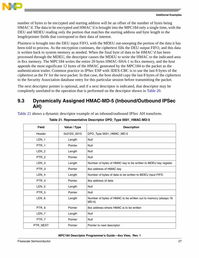
Plaintext is brought into the DEU input FIFO, with the MDEU out-snooping the portion of the data it has been told to process. As the encryption continues, the ciphertext fills the DEU output FIFO, and this data is written back to system memory as needed. When the final byte of data to be HMAC’d has been processed through the MDEU, the descriptor causes the MDEU to write the HMAC to the indicated area in 8xx memory. The MPC184 writes the entire 20 bytes HMAC-SHA-1 to 8xx memory, and the host appends the most significant 12 bytes of the HMAC generated by the MPC184 to the packet as the authentication trailer. Common practice in IPSec ESP with 3DES-CBC is to use the last 8 bytes of the ciphertext as the IV for the next packet. In that case, the host should copy the last 8 bytes of the ciphertext to the Security Association database entry for this particular session before transmitting the packet.
The next descriptor pointer is optional, and if a next descriptor is indicated, that descriptor may be completely unrelated to the operation that is performed on the descriptor shown in Table 20.
9.3 Dynamically Assigned HMAC-MD-5 (Inbound/Outbound IPSec AH)
Table 21 shows a dynamic descriptor example of an inbound/outbound IPSec AH transform.Table 21. Representative Descriptor DPD_Type 0001_HMAC-MD-5
Field Value / Type Description
Header 0x31E0_0010 DPD_Type 0001_HMAC_MD-5
LEN_1 Length Null
PTR_1 Pointer Null
LEN_2 Length Null
PTR_2 Pointer Null
LEN_3 Length Number of bytes of HMAC key to be written to MDEU key register
PTR_3 Pointer 8xx address of HMAC key
LEN_4 Length Number of bytes of data to be written to MDEU input FIFO
PTR_4 Pointer 8xx address of data
LEN_5 Length Null
PTR_5 Pointer Null
LEN_6 Length Number of bytes of HMAC to be written out to memory (always 16 MD-5)
PTR_6 Pointer 8xx address where HMAC is to be written
LEN_7 Length Null
PTR_7 Pointer Null
PTR_NEXT Pointer Pointer to next descriptor
MPC184 Descriptor Programmer’s Guide—8xx View, Rev. 1
28 Freescale Semiconductor
Additional Examples
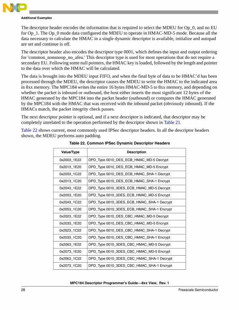
The descriptor header encodes the information that is required to select the MDEU for Op_0, and no EU for Op_1. The Op_0 mode data configured the MDEU to operate in HMAC-MD-5 mode. Because all the data necessary to calculate the HMAC in a single dynamic descriptor is available, initialize and autopad are set and continue is off.
The descriptor header also encodes the descriptor type 0001, which defines the input and output ordering for 'common_nonsnoop_no_afeu.' This descriptor type is used for most operations that do not require a secondary EU. Following some null pointers, the HMAC key is loaded, followed by the length and pointer to the data over which the HMAC will be calculated.
The data is brought into the MDEU input FIFO, and when the final byte of data to be HMAC’d has been processed through the MDEU, the descriptor causes the MDEU to write the HMAC to the indicated area in 8xx memory. The MPC184 writes the entire 16 bytes HMAC-MD-5 to 8xx memory, and depending on whether the packet is inbound or outbound, the host either inserts the most significant 12 bytes of the HMAC generated by the MPC184 into the packet header (outbound) or compares the HMAC generated by the MPC184 with the HMAC that was received with the inbound packet (obviously inbound). If the HMACs match, the packet integrity check passes.
The next descriptor pointer is optional, and if a next descriptor is indicated, that descriptor may be completely unrelated to the operation performed by the descriptor shown in Table 21.
Table 22 shows current, most commonly used IPSec descriptor headers. In all the descriptor headers shown, the MDEU performs auto padding.
Table 22. Common IPSec Dynamic Descriptor Headers
Value/Type Description
0x2003_1E22 DPD_Type 0010_DES_ECB_HMAC_MD-5 Decrypt
0x2013_1E20 DPD_Type 0010_DES_ECB_HMAC_MD-5 Encrypt
0x2003_1C22 DPD_Type 0010_DES_ECB_HMAC_SHA-1 Decrypt
0x2013_1C20 DPD_Type 0010_DES_ECB_HMAC_SHA-1 Encrypt
0x2043_1E22 DPD_Type 0010_3DES_ECB_HMAC_MD-5 Decrypt
0x2053_1E20 DPD_Type 0010_3DES_ECB_HMAC_MD-5 Encrypt
0x2043_1C22 DPD_Type 0010_3DES_ECB_HMAC_SHA-1 Decrypt
0x2053_1C20 DPD_Type 0010_3DES_ECB_HMAC_SHA-1 Encrypt
0x2023_1E22 DPD_Type 0010_DES_CBC_HMAC_MD-5 Decrypt
0x2033_1E20 DPD_Type 0010_DES_CBC_HMAC_MD-5 Encrypt
0x2023_1C22 DPD_Type 0010_DES_CBC_HMAC_SHA-1 Decrypt
0x2033_1C20 DPD_Type 0010_DES_CBC_HMAC_SHA-1 Encrypt
0x2063_1E22 DPD_Type 0010_3DES_CBC_HMAC_MD-5 Decrypt
0x2073_1E20 DPD_Type 0010_3DES_CBC_HMAC_MD-5 Encrypt
0x2063_1C22 DPD_Type 0010_3DES_CBC_HMAC_SHA-1 Decrypt
0x2073_1C20 DPD_Type 0010_3DES_CBC_HMAC_SHA-1 Encrypt
MPC184 Descriptor Programmer’s Guide—8xx View, Rev. 1
Freescale Semiconductor 29
Additional Examples
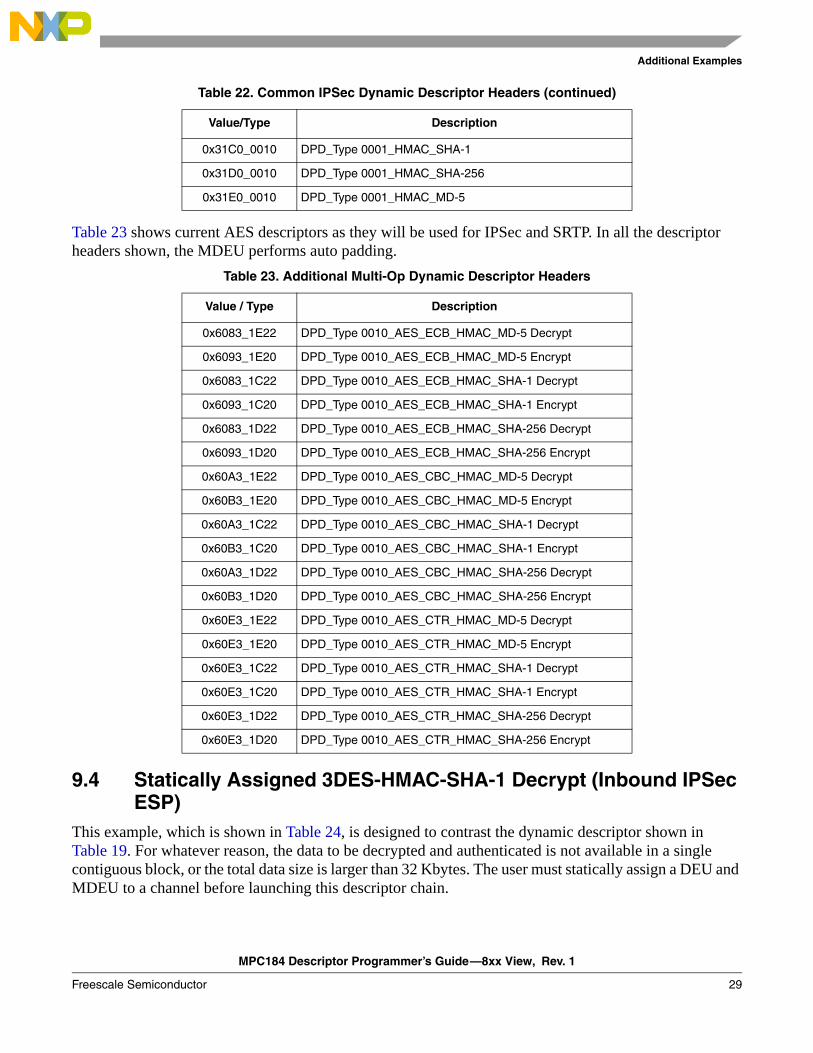
Table 23 shows current AES descriptors as they will be used for IPSec and SRTP. In all the descriptor headers shown, the MDEU performs auto padding.
9.4 Statically Assigned 3DES-HMAC-SHA-1 Decrypt (Inbound IPSec ESP)
This example, which is shown in Table 24, is designed to contrast the dynamic descriptor shown in Table 19. For whatever reason, the data to be decrypted and authenticated is not available in a single contiguous block, or the total data size is larger than 32 Kbytes. The user must statically assign a DEU and MDEU to a channel before launching this descriptor chain.
0x31C0_0010 DPD_Type 0001_HMAC_SHA-1
0x31D0_0010 DPD_Type 0001_HMAC_SHA-256
0x31E0_0010 DPD_Type 0001_HMAC_MD-5
Table 23. Additional Multi-Op Dynamic Descriptor Headers
Value / Type Description
0x6083_1E22 DPD_Type 0010_AES_ECB_HMAC_MD-5 Decrypt
0x6093_1E20 DPD_Type 0010_AES_ECB_HMAC_MD-5 Encrypt
0x6083_1C22 DPD_Type 0010_AES_ECB_HMAC_SHA-1 Decrypt
0x6093_1C20 DPD_Type 0010_AES_ECB_HMAC_SHA-1 Encrypt
0x6083_1D22 DPD_Type 0010_AES_ECB_HMAC_SHA-256 Decrypt
0x6093_1D20 DPD_Type 0010_AES_ECB_HMAC_SHA-256 Encrypt
0x60A3_1E22 DPD_Type 0010_AES_CBC_HMAC_MD-5 Decrypt
0x60B3_1E20 DPD_Type 0010_AES_CBC_HMAC_MD-5 Encrypt
0x60A3_1C22 DPD_Type 0010_AES_CBC_HMAC_SHA-1 Decrypt
0x60B3_1C20 DPD_Type 0010_AES_CBC_HMAC_SHA-1 Encrypt
0x60A3_1D22 DPD_Type 0010_AES_CBC_HMAC_SHA-256 Decrypt
0x60B3_1D20 DPD_Type 0010_AES_CBC_HMAC_SHA-256 Encrypt
0x60E3_1E22 DPD_Type 0010_AES_CTR_HMAC_MD-5 Decrypt
0x60E3_1E20 DPD_Type 0010_AES_CTR_HMAC_MD-5 Encrypt
0x60E3_1C22 DPD_Type 0010_AES_CTR_HMAC_SHA-1 Decrypt
0x60E3_1C20 DPD_Type 0010_AES_CTR_HMAC_SHA-1 Encrypt
0x60E3_1D22 DPD_Type 0010_AES_CTR_HMAC_SHA-256 Decrypt
0x60E3_1D20 DPD_Type 0010_AES_CTR_HMAC_SHA-256 Encrypt
Table 22. Common IPSec Dynamic Descriptor Headers (continued)
Value/Type Description
MPC184 Descriptor Programmer’s Guide—8xx View, Rev. 1
30 Freescale Semiconductor
Additional Examples
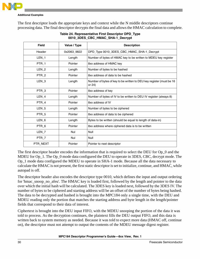
The first descriptor loads the appropriate keys and context while the N middle descriptors continue processing data. The final descriptor decrypts the final data and allows the HMAC calculation to complete.
The first descriptor header encodes the information that is required to select the DEU for Op_0 and the MDEU for Op_1. The Op_0 mode data configured the DEU to operate in 3DES, CBC, decrypt mode. The Op_1 mode data configured the MDEU to operate in SHA-1 mode. Because all the data necessary to calculate the HMAC is not present, the first static descriptor is set to initialize, continue, and HMAC, while autopad is off.
The descriptor header also encodes the descriptor type 0010, which defines the input and output ordering for 'hmac_snoop_no_afeu'. The HMAC key is loaded first, followed by the length and pointer to the data over which the initial hash will be calculated. The 3DES key is loaded next, followed by the 3DES IV. The number of bytes to be ciphered and starting address will be an offset of the number of bytes being hashed. The data to be decrypted and hashed is brought into the MPC184 only a single time, with the DEU and MDEU reading only the portion that matches the starting address and byte length in the length/pointer fields that correspond to their data of interest.
Ciphertext is brought into the DEU input FIFO, with the MDEU snooping the portion of the data it was told to process. As the decryption continues, the plaintext fills the DEU output FIFO, and this data is written back to system memory as needed. Because it was told to expect more data (HMAC off, continue on), the descriptor must not attempt to output the contents of the MDEU message digest register.
Table 24. Representative First Descriptor DPD_Type 0010_3DES_CBC_HMAC_SHA-1_Decrypt
Field Value / Type Description
Header 0x2063_9822 DPD_Type 0010_3DES_CBC_HMAC_SHA-1_Decrypt
LEN_1 Length Number of bytes of HMAC key to be written to MDEU key register
PTR_1 Pointer 8xx address of HMAC key
LEN_2 Length Number of bytes to be hashed
PTR_2 Pointer 8xx address of data to be hashed
LEN_3 Length Number of bytes of key to be written to DEU key register (must be 16 or 24)
PTR_3 Pointer 8xx address of key
LEN_4 Length Number of bytes of IV to be written to DEU IV register (always 8)
PTR_4 Pointer 8xx address of IV
LEN_5 Length Number of bytes to be ciphered
PTR_5 Pointer 8xx address of data to be ciphered
LEN_6 Length Bytes to be written (should be equal to length of data-in)
PTR_6 Pointer 8xx address where ciphered data is to be written
LEN_7 Nul Null
PTR_7 Nul Null
PTR_NEXT Pointer Pointer to next descriptor
MPC184 Descriptor Programmer’s Guide—8xx View, Rev. 1
Freescale Semiconductor 31
Additional Examples
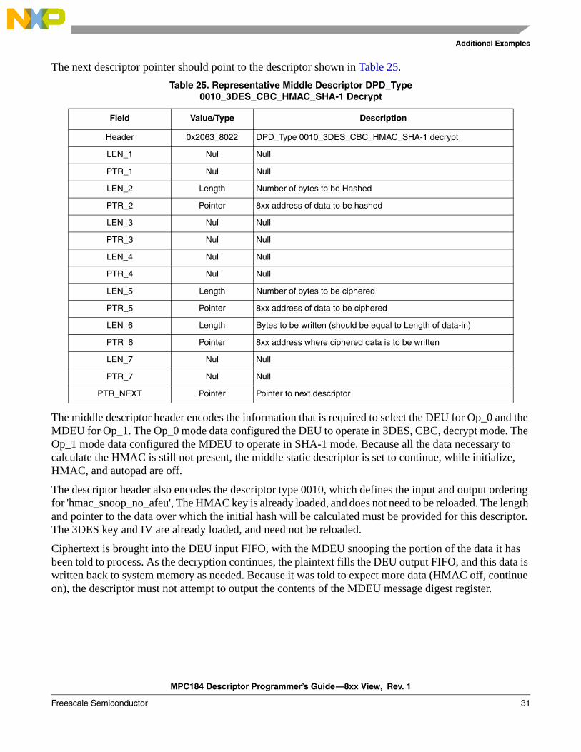
The next descriptor pointer should point to the descriptor shown in Table 25.
The middle descriptor header encodes the information that is required to select the DEU for Op_0 and the MDEU for Op_1. The Op_0 mode data configured the DEU to operate in 3DES, CBC, decrypt mode. The Op_1 mode data configured the MDEU to operate in SHA-1 mode. Because all the data necessary to calculate the HMAC is still not present, the middle static descriptor is set to continue, while initialize, HMAC, and autopad are off.
The descriptor header also encodes the descriptor type 0010, which defines the input and output ordering for 'hmac_snoop_no_afeu', The HMAC key is already loaded, and does not need to be reloaded. The length and pointer to the data over which the initial hash will be calculated must be provided for this descriptor. The 3DES key and IV are already loaded, and need not be reloaded.
Ciphertext is brought into the DEU input FIFO, with the MDEU snooping the portion of the data it has been told to process. As the decryption continues, the plaintext fills the DEU output FIFO, and this data is written back to system memory as needed. Because it was told to expect more data (HMAC off, continue on), the descriptor must not attempt to output the contents of the MDEU message digest register.
Table 25. Representative Middle Descriptor DPD_Type 0010_3DES_CBC_HMAC_SHA-1 Decrypt
Field Value/Type Description
Header 0x2063_8022 DPD_Type 0010_3DES_CBC_HMAC_SHA-1 decrypt
LEN_1 Nul Null
PTR_1 Nul Null
LEN_2 Length Number of bytes to be Hashed
PTR_2 Pointer 8xx address of data to be hashed
LEN_3 Nul Null
PTR_3 Nul Null
LEN_4 Nul Null
PTR_4 Nul Null
LEN_5 Length Number of bytes to be ciphered
PTR_5 Pointer 8xx address of data to be ciphered
LEN_6 Length Bytes to be written (should be equal to Length of data-in)
PTR_6 Pointer 8xx address where ciphered data is to be written
LEN_7 Nul Null
PTR_7 Nul Null
PTR_NEXT Pointer Pointer to next descriptor
MPC184 Descriptor Programmer’s Guide—8xx View, Rev. 1
32 Freescale Semiconductor
Additional Examples
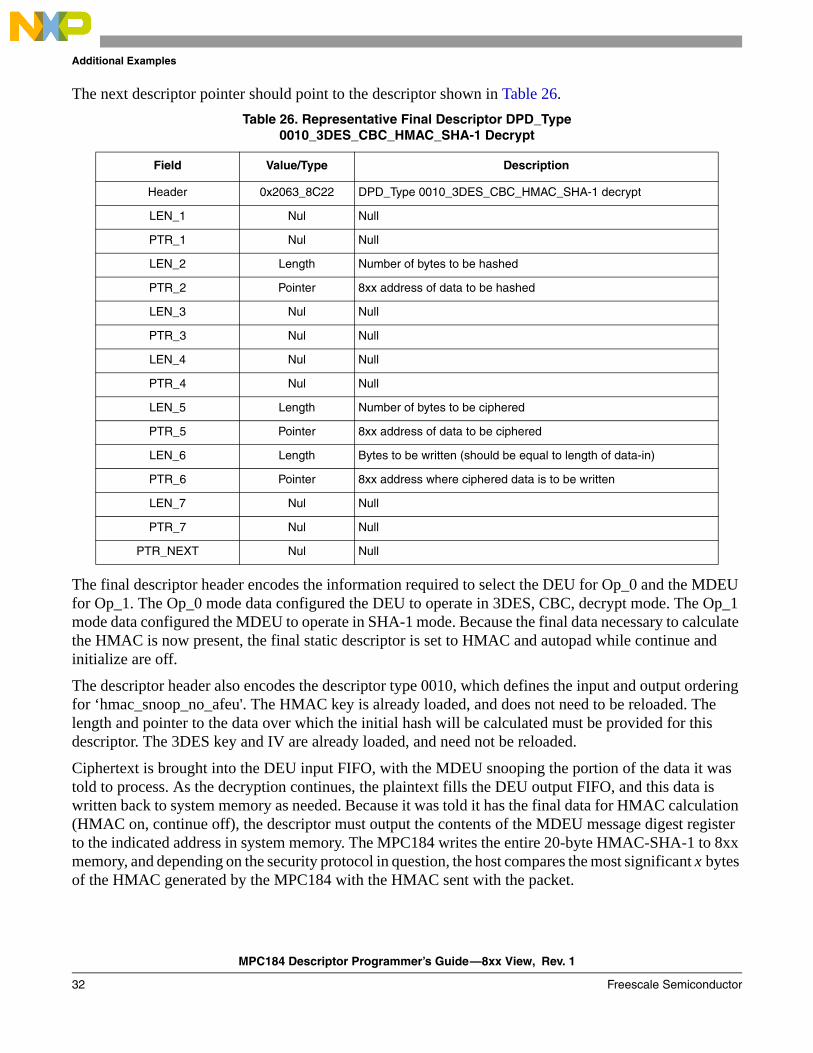
The next descriptor pointer should point to the descriptor shown in Table 26.
The final descriptor header encodes the information required to select the DEU for Op_0 and the MDEU for Op_1. The Op_0 mode data configured the DEU to operate in 3DES, CBC, decrypt mode. The Op_1 mode data configured the MDEU to operate in SHA-1 mode. Because the final data necessary to calculate the HMAC is now present, the final static descriptor is set to HMAC and autopad while continue and initialize are off.
The descriptor header also encodes the descriptor type 0010, which defines the input and output ordering for ‘hmac_snoop_no_afeu'. The HMAC key is already loaded, and does not need to be reloaded. The length and pointer to the data over which the initial hash will be calculated must be provided for this descriptor. The 3DES key and IV are already loaded, and need not be reloaded.
Ciphertext is brought into the DEU input FIFO, with the MDEU snooping the portion of the data it was told to process. As the decryption continues, the plaintext fills the DEU output FIFO, and this data is written back to system memory as needed. Because it was told it has the final data for HMAC calculation (HMAC on, continue off), the descriptor must output the contents of the MDEU message digest register to the indicated address in system memory. The MPC184 writes the entire 20-byte HMAC-SHA-1 to 8xx memory, and depending on the security protocol in question, the host compares the most significant x bytes of the HMAC generated by the MPC184 with the HMAC sent with the packet.
Table 26. Representative Final Descriptor DPD_Type 0010_3DES_CBC_HMAC_SHA-1 Decrypt
Field Value/Type Description
Header 0x2063_8C22 DPD_Type 0010_3DES_CBC_HMAC_SHA-1 decrypt
LEN_1 Nul Null
PTR_1 Nul Null
LEN_2 Length Number of bytes to be hashed
PTR_2 Pointer 8xx address of data to be hashed
LEN_3 Nul Null
PTR_3 Nul Null
LEN_4 Nul Null
PTR_4 Nul Null
LEN_5 Length Number of bytes to be ciphered
PTR_5 Pointer 8xx address of data to be ciphered
LEN_6 Length Bytes to be written (should be equal to length of data-in)
PTR_6 Pointer 8xx address where ciphered data is to be written
LEN_7 Nul Null
PTR_7 Nul Null
PTR_NEXT Nul Null
MPC184 Descriptor Programmer’s Guide—8xx View, Rev. 1
Freescale Semiconductor 33
Additional Examples
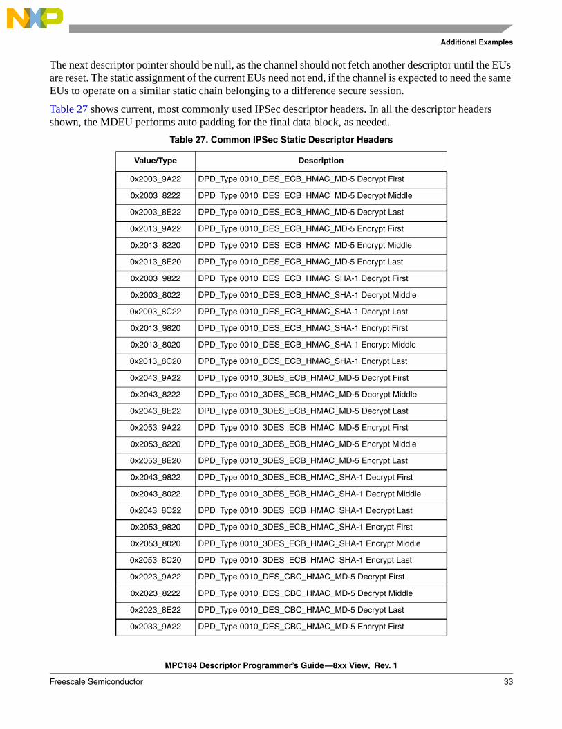
The next descriptor pointer should be null, as the channel should not fetch another descriptor until the EUs are reset. The static assignment of the current EUs need not end, if the channel is expected to need the same EUs to operate on a similar static chain belonging to a difference secure session.
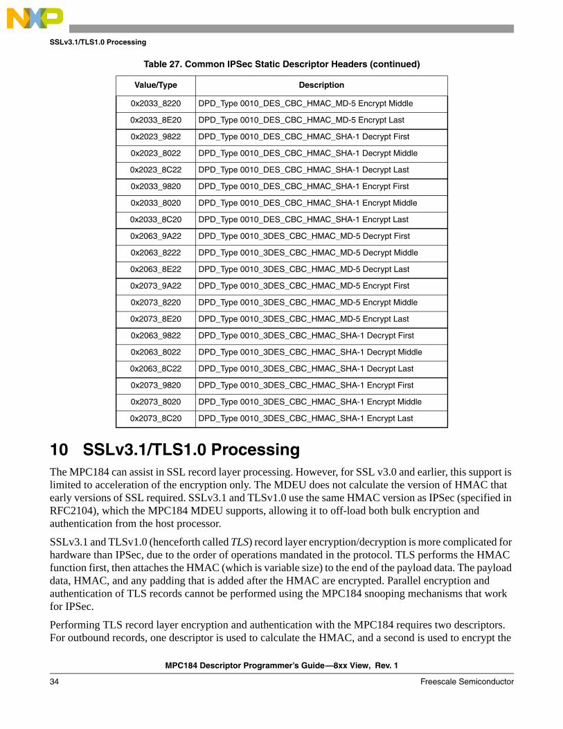
Table 27 shows current, most commonly used IPSec descriptor headers. In all the descriptor headers shown, the MDEU performs auto padding for the final data block, as needed.
Table 27. Common IPSec Static Descriptor Headers
Value/Type Description
0x2003_9A22 DPD_Type 0010_DES_ECB_HMAC_MD-5 Decrypt First
0x2003_8222 DPD_Type 0010_DES_ECB_HMAC_MD-5 Decrypt Middle
0x2003_8E22 DPD_Type 0010_DES_ECB_HMAC_MD-5 Decrypt Last
0x2013_9A22 DPD_Type 0010_DES_ECB_HMAC_MD-5 Encrypt First
0x2013_8220 DPD_Type 0010_DES_ECB_HMAC_MD-5 Encrypt Middle
0x2013_8E20 DPD_Type 0010_DES_ECB_HMAC_MD-5 Encrypt Last
0x2003_9822 DPD_Type 0010_DES_ECB_HMAC_SHA-1 Decrypt First
0x2003_8022 DPD_Type 0010_DES_ECB_HMAC_SHA-1 Decrypt Middle
0x2003_8C22 DPD_Type 0010_DES_ECB_HMAC_SHA-1 Decrypt Last
0x2013_9820 DPD_Type 0010_DES_ECB_HMAC_SHA-1 Encrypt First
0x2013_8020 DPD_Type 0010_DES_ECB_HMAC_SHA-1 Encrypt Middle
0x2013_8C20 DPD_Type 0010_DES_ECB_HMAC_SHA-1 Encrypt Last
0x2043_9A22 DPD_Type 0010_3DES_ECB_HMAC_MD-5 Decrypt First
0x2043_8222 DPD_Type 0010_3DES_ECB_HMAC_MD-5 Decrypt Middle
0x2043_8E22 DPD_Type 0010_3DES_ECB_HMAC_MD-5 Decrypt Last
0x2053_9A22 DPD_Type 0010_3DES_ECB_HMAC_MD-5 Encrypt First
0x2053_8220 DPD_Type 0010_3DES_ECB_HMAC_MD-5 Encrypt Middle
0x2053_8E20 DPD_Type 0010_3DES_ECB_HMAC_MD-5 Encrypt Last
0x2043_9822 DPD_Type 0010_3DES_ECB_HMAC_SHA-1 Decrypt First
0x2043_8022 DPD_Type 0010_3DES_ECB_HMAC_SHA-1 Decrypt Middle
0x2043_8C22 DPD_Type 0010_3DES_ECB_HMAC_SHA-1 Decrypt Last
0x2053_9820 DPD_Type 0010_3DES_ECB_HMAC_SHA-1 Encrypt First
0x2053_8020 DPD_Type 0010_3DES_ECB_HMAC_SHA-1 Encrypt Middle
0x2053_8C20 DPD_Type 0010_3DES_ECB_HMAC_SHA-1 Encrypt Last
0x2023_9A22 DPD_Type 0010_DES_CBC_HMAC_MD-5 Decrypt First
0x2023_8222 DPD_Type 0010_DES_CBC_HMAC_MD-5 Decrypt Middle
0x2023_8E22 DPD_Type 0010_DES_CBC_HMAC_MD-5 Decrypt Last
0x2033_9A22 DPD_Type 0010_DES_CBC_HMAC_MD-5 Encrypt First
MPC184 Descriptor Programmer’s Guide—8xx View, Rev. 1
34 Freescale Semiconductor
SSLv3.1/TLS1.0 Processing
10 SSLv3.1/TLS1.0 ProcessingThe MPC184 can assist in SSL record layer processing. However, for SSL v3.0 and earlier, this support is limited to acceleration of the encryption only. The MDEU does not calculate the version of HMAC that early versions of SSL required. SSLv3.1 and TLSv1.0 use the same HMAC version as IPSec (specified in RFC2104), which the MPC184 MDEU supports, allowing it to off-load both bulk encryption and authentication from the host processor.
SSLv3.1 and TLSv1.0 (henceforth called TLS) record layer encryption/decryption is more complicated for hardware than IPSec, due to the order of operations mandated in the protocol. TLS performs the HMAC function first, then attaches the HMAC (which is variable size) to the end of the payload data. The payload data, HMAC, and any padding that is added after the HMAC are encrypted. Parallel encryption and authentication of TLS records cannot be performed using the MPC184 snooping mechanisms that work for IPSec.
Performing TLS record layer encryption and authentication with the MPC184 requires two descriptors. For outbound records, one descriptor is used to calculate the HMAC, and a second is used to encrypt the
0x2033_8220 DPD_Type 0010_DES_CBC_HMAC_MD-5 Encrypt Middle
0x2033_8E20 DPD_Type 0010_DES_CBC_HMAC_MD-5 Encrypt Last
0x2023_9822 DPD_Type 0010_DES_CBC_HMAC_SHA-1 Decrypt First
0x2023_8022 DPD_Type 0010_DES_CBC_HMAC_SHA-1 Decrypt Middle
0x2023_8C22 DPD_Type 0010_DES_CBC_HMAC_SHA-1 Decrypt Last
0x2033_9820 DPD_Type 0010_DES_CBC_HMAC_SHA-1 Encrypt First
0x2033_8020 DPD_Type 0010_DES_CBC_HMAC_SHA-1 Encrypt Middle
0x2033_8C20 DPD_Type 0010_DES_CBC_HMAC_SHA-1 Encrypt Last
0x2063_9A22 DPD_Type 0010_3DES_CBC_HMAC_MD-5 Decrypt First
0x2063_8222 DPD_Type 0010_3DES_CBC_HMAC_MD-5 Decrypt Middle
0x2063_8E22 DPD_Type 0010_3DES_CBC_HMAC_MD-5 Decrypt Last
0x2073_9A22 DPD_Type 0010_3DES_CBC_HMAC_MD-5 Encrypt First
0x2073_8220 DPD_Type 0010_3DES_CBC_HMAC_MD-5 Encrypt Middle
0x2073_8E20 DPD_Type 0010_3DES_CBC_HMAC_MD-5 Encrypt Last
0x2063_9822 DPD_Type 0010_3DES_CBC_HMAC_SHA-1 Decrypt First
0x2063_8022 DPD_Type 0010_3DES_CBC_HMAC_SHA-1 Decrypt Middle
0x2063_8C22 DPD_Type 0010_3DES_CBC_HMAC_SHA-1 Decrypt Last
0x2073_9820 DPD_Type 0010_3DES_CBC_HMAC_SHA-1 Encrypt First
0x2073_8020 DPD_Type 0010_3DES_CBC_HMAC_SHA-1 Encrypt Middle
0x2073_8C20 DPD_Type 0010_3DES_CBC_HMAC_SHA-1 Encrypt Last
Table 27. Common IPSec Static Descriptor Headers (continued)
Value/Type Description
MPC184 Descriptor Programmer’s Guide—8xx View, Rev. 1
Freescale Semiconductor 35
SSLv3.1/TLS1.0 Processing
record, HMAC, and padding. For inbound records, the first descriptor decrypts the record, while the second descriptor is used to recalculate the HMAC for validation by the host. With some planning, the programmer may create the outbound descriptors and launch them as a chain, leaving the MPC194 to complete the full HMAC/encrypt operation before signaling DONE. Placing the output from descriptor 1 into the MPC184 on-chip gpRAM, then fetching that data is input for descriptor 2 can provide additional bus bandwidth savings, and improve system performance. For inbound records, the MPC184 will signal DONE after decryption so that the host can determine the location of the HMAC before setting up the HMAC validation descriptor.
The following sections provide examples and explanations covering TLS outbound and inbound processing using dynamic assignment.
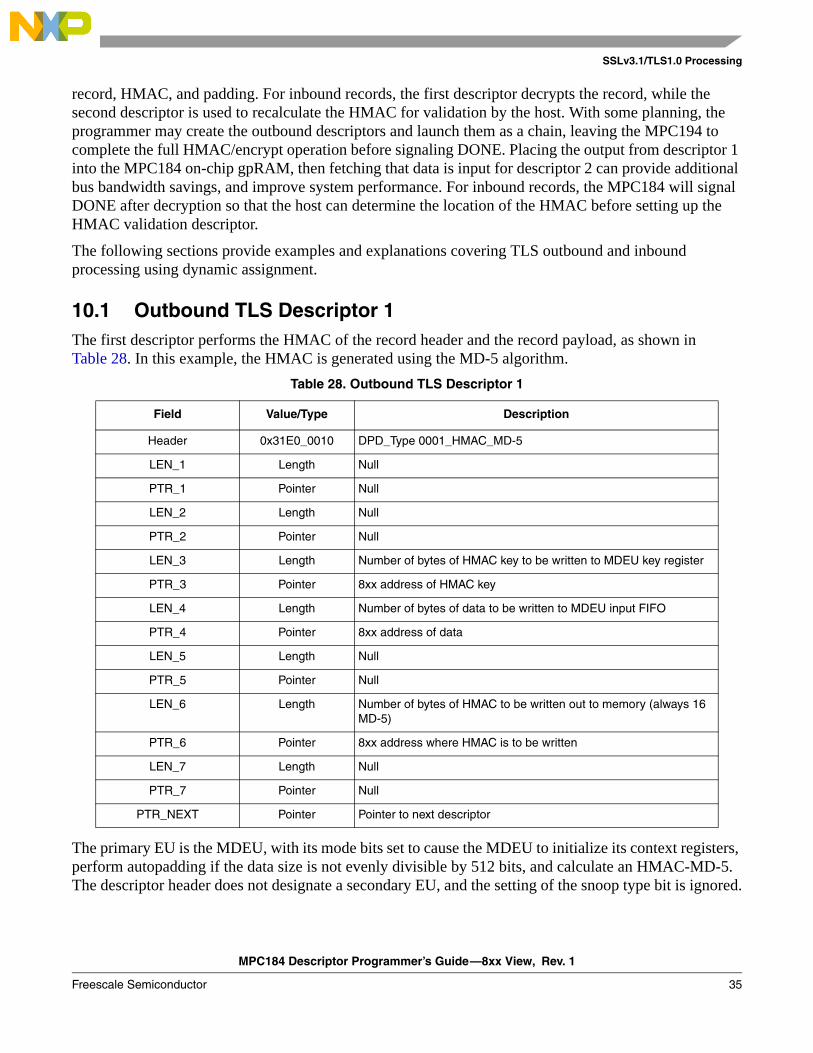
10.1 Outbound TLS Descriptor 1 The first descriptor performs the HMAC of the record header and the record payload, as shown in Table 28. In this example, the HMAC is generated using the MD-5 algorithm.
The primary EU is the MDEU, with its mode bits set to cause the MDEU to initialize its context registers, perform autopadding if the data size is not evenly divisible by 512 bits, and calculate an HMAC-MD-5. The descriptor header does not designate a secondary EU, and the setting of the snoop type bit is ignored.
Table 28. Outbound TLS Descriptor 1
Field Value/Type Description
Header 0x31E0_0010 DPD_Type 0001_HMAC_MD-5
LEN_1 Length Null
PTR_1 Pointer Null
LEN_2 Length Null
PTR_2 Pointer Null
LEN_3 Length Number of bytes of HMAC key to be written to MDEU key register
PTR_3 Pointer 8xx address of HMAC key
LEN_4 Length Number of bytes of data to be written to MDEU input FIFO
PTR_4 Pointer 8xx address of data
LEN_5 Length Null
PTR_5 Pointer Null
LEN_6 Length Number of bytes of HMAC to be written out to memory (always 16 MD-5)
PTR_6 Pointer 8xx address where HMAC is to be written
LEN_7 Length Null
PTR_7 Pointer Null
PTR_NEXT Pointer Pointer to next descriptor
MPC184 Descriptor Programmer’s Guide—8xx View, Rev. 1
36 Freescale Semiconductor
SSLv3.1/TLS1.0 Processing
At the conclusion of outbound TLS descriptor 1, the crypto-channel has calculated the HMAC, placed it in memory, and reset and released the MDEU.
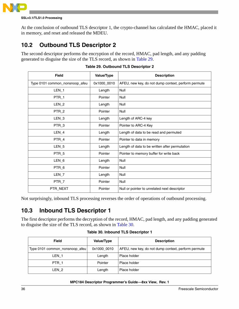
10.2 Outbound TLS Descriptor 2 The second descriptor performs the encryption of the record, HMAC, pad length, and any padding generated to disguise the size of the TLS record, as shown in Table 29.
Not surprisingly, inbound TLS processing reverses the order of operations of outbound processing.
10.3 Inbound TLS Descriptor 1The first descriptor performs the decryption of the record, HMAC, pad length, and any padding generated to disguise the size of the TLS record, as shown in Table 30.
Table 29. Outbound TLS Descriptor 2
Field Value/Type Description
Type 0101 common_nonsnoop_afeu 0x1000_0010 AFEU, new key, do not dump context, perform permute
LEN_1 Length Null
PTR_1 Pointer Null
LEN_2 Length Null
PTR_2 Pointer Null
LEN_3 Length Length of ARC-4 key
PTR_3 Pointer Pointer to ARC-4 Key
LEN_4 Length Length of data to be read and permuted
PTR_4 Pointer Pointer to data in memory
LEN_5 Length Length of data to be written after permutation
PTR_5 Pointer Pointer to memory buffer for write back
LEN_6 Length Null
PTR_6 Pointer Null
LEN_7 Length Null
PTR_7 Pointer Null
PTR_NEXT Pointer Null or pointer to unrelated next descriptor
Table 30. Inbound TLS Descriptor 1
Field Value/Type Description
Type 0101 common_nonsnoop_afeu 0x1000_0010 AFEU, new key, do not dump context, perform permute
LEN_1 Length Place holder
PTR_1 Pointer Place holder
LEN_2 Length Place holder
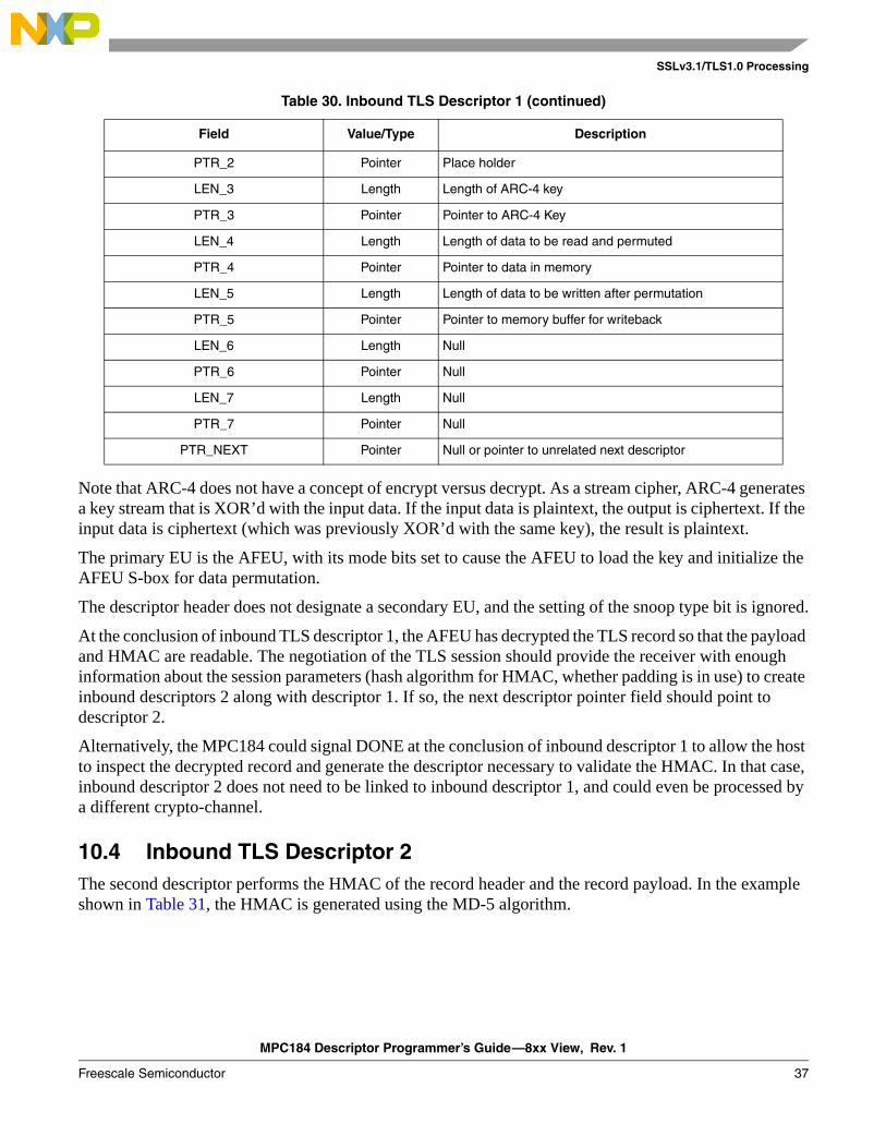
MPC184 Descriptor Programmer’s Guide—8xx View, Rev. 1
Freescale Semiconductor 37
SSLv3.1/TLS1.0 Processing
Note that ARC-4 does not have a concept of encrypt versus decrypt. As a stream cipher, ARC-4 generates a key stream that is XOR’d with the input data. If the input data is plaintext, the output is ciphertext. If the input data is ciphertext (which was previously XOR’d with the same key), the result is plaintext.
The primary EU is the AFEU, with its mode bits set to cause the AFEU to load the key and initialize the AFEU S-box for data permutation.
The descriptor header does not designate a secondary EU, and the setting of the snoop type bit is ignored.
At the conclusion of inbound TLS descriptor 1, the AFEU has decrypted the TLS record so that the payload and HMAC are readable. The negotiation of the TLS session should provide the receiver with enough information about the session parameters (hash algorithm for HMAC, whether padding is in use) to create inbound descriptors 2 along with descriptor 1. If so, the next descriptor pointer field should point to descriptor 2.
Alternatively, the MPC184 could signal DONE at the conclusion of inbound descriptor 1 to allow the host to inspect the decrypted record and generate the descriptor necessary to validate the HMAC. In that case, inbound descriptor 2 does not need to be linked to inbound descriptor 1, and could even be processed by a different crypto-channel.
10.4 Inbound TLS Descriptor 2The second descriptor performs the HMAC of the record header and the record payload. In the example shown in Table 31, the HMAC is generated using the MD-5 algorithm.
PTR_2 Pointer Place holder
LEN_3 Length Length of ARC-4 key
PTR_3 Pointer Pointer to ARC-4 Key
LEN_4 Length Length of data to be read and permuted
PTR_4 Pointer Pointer to data in memory
LEN_5 Length Length of data to be written after permutation
PTR_5 Pointer Pointer to memory buffer for writeback
LEN_6 Length Null
PTR_6 Pointer Null
LEN_7 Length Null
PTR_7 Pointer Null
PTR_NEXT Pointer Null or pointer to unrelated next descriptor
Table 30. Inbound TLS Descriptor 1 (continued)
Field Value/Type Description
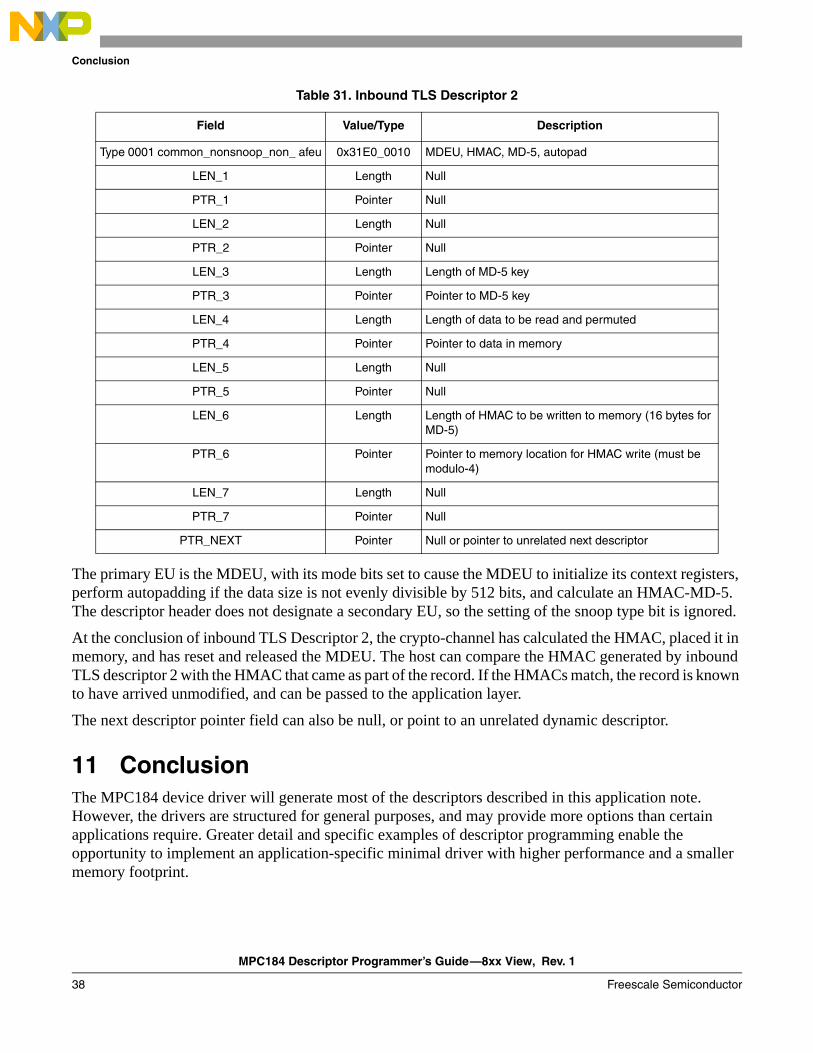
MPC184 Descriptor Programmer’s Guide—8xx View, Rev. 1
38 Freescale Semiconductor
Conclusion
The primary EU is the MDEU, with its mode bits set to cause the MDEU to initialize its context registers, perform autopadding if the data size is not evenly divisible by 512 bits, and calculate an HMAC-MD-5. The descriptor header does not designate a secondary EU, so the setting of the snoop type bit is ignored.
At the conclusion of inbound TLS Descriptor 2, the crypto-channel has calculated the HMAC, placed it in memory, and has reset and released the MDEU. The host can compare the HMAC generated by inbound TLS descriptor 2 with the HMAC that came as part of the record. If the HMACs match, the record is known to have arrived unmodified, and can be passed to the application layer.
The next descriptor pointer field can also be null, or point to an unrelated dynamic descriptor.
11 ConclusionThe MPC184 device driver will generate most of the descriptors described in this application note. However, the drivers are structured for general purposes, and may provide more options than certain applications require. Greater detail and specific examples of descriptor programming enable the opportunity to implement an application-specific minimal driver with higher performance and a smaller memory footprint.
Table 31. Inbound TLS Descriptor 2
Field Value/Type Description
Type 0001 common_nonsnoop_non_ afeu 0x31E0_0010 MDEU, HMAC, MD-5, autopad
LEN_1 Length Null
PTR_1 Pointer Null
LEN_2 Length Null
PTR_2 Pointer Null
LEN_3 Length Length of MD-5 key
PTR_3 Pointer Pointer to MD-5 key
LEN_4 Length Length of data to be read and permuted
PTR_4 Pointer Pointer to data in memory
LEN_5 Length Null
PTR_5 Pointer Null
LEN_6 Length Length of HMAC to be written to memory (16 bytes for MD-5)
PTR_6 Pointer Pointer to memory location for HMAC write (must be modulo-4)
LEN_7 Length Null
PTR_7 Pointer Null
PTR_NEXT Pointer Null or pointer to unrelated next descriptor
MPC184 Descriptor Programmer’s Guide—8xx View, Rev. 1
Freescale Semiconductor 39
Revision History
12 Revision History Table 32 provides a revision history for this application note.
Table 32. Document Revision History
Rev.Number
Date Substantive Change(s)
1 10/29/2006 Document template update.
0 08/22/2003 Initial release.
Document Number: AN2576Rev. 110/2006
Freescale™ and the Freescale logo are trademarks of Freescale Semiconductor, Inc. All other product or service names are the property of their respective owners.
© Freescale Semiconductor, Inc., 2003, 2006.
Information in this document is provided solely to enable system and software
implementers to use Freescale Semiconductor products. There are no express or
implied copyright licenses granted hereunder to design or fabricate any integrated
circuits or integrated circuits based on the information in this document.
Freescale Semiconductor reserves the right to make changes without further notice to
any products herein. Freescale Semiconductor makes no warranty, representation or
guarantee regarding the suitability of its products for any particular purpose, nor does
Freescale Semiconductor assume any liability arising out of the application or use of
any product or circuit, and specifically disclaims any and all liability, including without
limitation consequential or incidental damages. “Typical” parameters which may be
provided in Freescale Semiconductor data sheets and/or specifications can and do
vary in different applications and actual performance may vary over time. All operating
parameters, including “Typicals” must be validated for each customer application by
customer’s technical experts. Freescale Semiconductor does not convey any license
under its patent rights nor the rights of others. Freescale Semiconductor products are
not designed, intended, or authorized for use as components in systems intended for
surgical implant into the body, or other applications intended to support or sustain life,
or for any other application in which the failure of the Freescale Semiconductor product
could create a situation where personal injury or death may occur. Should Buyer
purchase or use Freescale Semiconductor products for any such unintended or
unauthorized application, Buyer shall indemnify and hold Freescale Semiconductor
and its officers, employees, subsidiaries, affiliates, and distributors harmless against all
claims, costs, damages, and expenses, and reasonable attorney fees arising out of,
directly or indirectly, any claim of personal injury or death associated with such
unintended or unauthorized use, even if such claim alleges that Freescale
Semiconductor was negligent regarding the design or manufacture of the part.
How to Reach Us:
Home Page: www.freescale.com
email: [email protected]
USA/Europe or Locations Not Listed: Freescale Semiconductor Technical Information Center, CH3701300 N. Alma School Road Chandler, Arizona 85224 [email protected]
Europe, Middle East, and Africa:Freescale Halbleiter Deutschland GmbHTechnical Information CenterSchatzbogen 781829 Muenchen, Germany+44 1296 380 456 (English) +46 8 52200080 (English)+49 89 92103 559 (German)+33 1 69 35 48 48 (French) [email protected]
Japan: Freescale Semiconductor Japan Ltd. HeadquartersARCO Tower 15F1-8-1, Shimo-Meguro, Meguro-ku Tokyo 153-0064, Japan 0120 191014+81 3 5437 [email protected]
Asia/Pacific: Freescale Semiconductor Hong Kong Ltd. Technical Information Center2 Dai King Street Tai Po Industrial Estate, Tai Po, N.T., Hong Kong +800 2666 [email protected]
For Literature Requests Only:Freescale Semiconductor
Literature Distribution Center P.O. Box 5405Denver, Colorado 80217 1-800-441-2447303-675-2140Fax: 303-675-2150LDCForFreescaleSemiconductor
@hibbertgroup.com


![User Manua Srd 16xx, 8xx English_web 0722[1]](https://img.pdfslide.net/doc/110x75/577cdc9e1a28ab9e78aaf2db/user-manua-srd-16xx-8xx-englishweb-07221.jpg)