Embed Size (px)
Citation preview

mPowerTM Edge IntelligenceConduit AEP Software Guide
MPOWER EDGE INTELLIGENCE SOFTWARE GUIDE
2 mPowerTM Edge Intelligence Conduit AEP Software Guide
mPower Edge Intelligence Software GuideModels: MTCDT, MTCDTIP, MTCAP
Part Number: S000727 Version: 5.1
CopyrightThis publication may not be reproduced, in whole or in part, without the specific and express prior written permission signed by an executive officer ofMulti-Tech Systems, Inc. All rights reserved. Copyright © 2019 by Multi-Tech Systems, Inc.
Multi-Tech Systems, Inc. makes no representations or warranties, whether express, implied or by estoppels, with respect to the content, information,material and recommendations herein and specifically disclaims any implied warranties of merchantability, fitness for any particular purpose and non-infringement.
Multi-Tech Systems, Inc. reserves the right to revise this publication and to make changes from time to time in the content hereof without obligation ofMulti-Tech Systems, Inc. to notify any person or organization of such revisions or changes.
Legal NoticesThe MultiTech products are not designed, manufactured or intended for use, and should not be used, or sold or re-sold for use, in connection withapplications requiring fail-safe performance or in applications where the failure of the products would reasonably be expected to result in personal injury ordeath, significant property damage, or serious physical or environmental damage. Examples of such use include life support machines or other lifepreserving medical devices or systems, air traffic control or aircraft navigation or communications systems, control equipment for nuclear facilities, ormissile, nuclear, biological or chemical weapons or other military applications (“Restricted Applications”). Use of the products in such RestrictedApplications is at the user’s sole risk and liability.
MULTITECH DOES NOT WARRANT THAT THE TRANSMISSION OF DATA BY A PRODUCT OVER A CELLULAR COMMUNICATIONS NETWORK WILL BEUNINTERRUPTED, TIMELY, SECURE OR ERROR FREE, NOR DOES MULTITECH WARRANT ANY CONNECTION OR ACCESSIBILITY TO ANY CELLULARCOMMUNICATIONS NETWORK. MULTITECH WILL HAVE NO LIABILITY FOR ANY LOSSES, DAMAGES, OBLIGATIONS, PENALTIES, DEFICIENCIES, LIABILITIES,COSTS OR EXPENSES (INCLUDING WITHOUT LIMITATION REASONABLE ATTORNEYS FEES) RELATED TO TEMPORARY INABILITY TO ACCESS A CELLULARCOMMUNICATIONS NETWORK USING THE PRODUCTS.
Trademarks and Registered TrademarksMultiTech, the MultiTech logo, DeviceHQ, xDot, and MultiConnect and Conduit are registered trademarks and mPower mCard and mDot are trademarks ofMulti-Tech Systems, Inc. All other products and technologies are the trademarks or registered trademarks of their respective holders.
Contacting MultiTech
Knowledge BaseThe Knowledge Base provides immediate access to support information and resolutions for all MultiTech products. Visit http://www.multitech.com/kb.go.
Support PortalTo create an account and submit a support case directly to our technical support team, visit: https://support.multitech.com.
SupportBusiness Hours: M-F, 8am to 5pm CT
Country By Email By Phone
Europe, Middle East, Africa: [email protected] +(44) 118 959 7774
U.S., Canada, all others: [email protected] (800) 972-2439 or (763) 717-5863
WarrantyTo read the warranty statement for your product, visit https://www.multitech.com/legal/warranty. For other warranty options, visitwww.multitech.com/es.go.
World Headquarters
Multi-Tech Systems, Inc.
2205 Woodale Drive, Mounds View, MN 55112
Phone: (800) 328-9717 or (763) 785-3500
Fax (763) 785-9874
CONTENTS
mPowerTM Edge Intelligence Conduit AEP Software Guide 3
ContentsChapter 1 – Product Overview ................................................................................................................................. 7
About mPower Edge Intelligence.................................................................................................................................. 7
Chapter 2 – Using the Wizard to Configure Your Device........................................................................................... 8First-Time Setup ............................................................................................................................................................ 8
Chapter 3 – Home .................................................................................................................................................. 11Device Information ..................................................................................................................................................... 11
Chapter 4 – LoRaWAN............................................................................................................................................ 14LoRaWAN Network Settings ....................................................................................................................................... 14Key Management ....................................................................................................................................................... 24Gateways..................................................................................................................................................................... 28Devices ........................................................................................................................................................................ 29Device Sessions ........................................................................................................................................................... 29Device Groups ............................................................................................................................................................. 30Profiles ........................................................................................................................................................................ 31Packets ........................................................................................................................................................................ 34Downlink Queue.......................................................................................................................................................... 36Operations .................................................................................................................................................................. 37
Chapter 5 – Setup .................................................................................................................................................. 40Network Interfaces ..................................................................................................................................................... 40Global DNS .................................................................................................................................................................. 45WAN Setup.................................................................................................................................................................. 46
Editing Failover Configuration................................................................................................................................... 46Failover Configuration Fields .................................................................................................................................... 46
Configuring IP Address for LAN .................................................................................................................................. 47Configuring Dynamic Domain Naming System (DDNS) .............................................................................................. 47
Entering authentication information ....................................................................................................................... 48Forcing a DDNS server update .................................................................................................................................. 48
Configuring Dynamic Host Configuration Protocol (DHCP) Server ............................................................................ 48Assigning Fixed Addresses ....................................................................................................................................... 49
Configuring SNMP ....................................................................................................................................................... 49Configuring the Global Positioning System (GPS) ....................................................................................................... 51
GPS Server Configuration.......................................................................................................................................... 51Sending GPS information to a remote server .......................................................................................................... 52Configuring NMEA Sentences .................................................................................................................................. 52
SMTP Settings ............................................................................................................................................................. 52Configuring the Serial Port in Serial IP Mode ............................................................................................................. 53Configuring Device to Act as Client for Serial IP ......................................................................................................... 53
CONTENTS
4 mPowerTM Edge Intelligence Conduit AEP Software Guide
Configuring Device to Act as Server for Serial IP ........................................................................................................ 55Time Configuration .................................................................................................................................................... 56
Setting the Date and Time ....................................................................................................................................... 56Configuring SNTP Client to Update Date and Time ................................................................................................. 56
Chapter 6 – Wireless .............................................................................................................................................. 57Setting Up Wi-Fi Access Point ..................................................................................................................................... 57
Setting Security Options ........................................................................................................................................... 57Viewing Information About Wi-Fi Clients Using Your Wireless Network ................................................................. 58
Setting Up Wi-Fi as WAN ............................................................................................................................................ 58Setting up Bluetooth .................................................................................................................................................. 59
IP Pipe in TCP/UDP Server mode .............................................................................................................................. 59To configure the IP Pipe in TCP/UDP Client mode.................................................................................................... 59
Bluetooth Low Energy (BLE)........................................................................................................................................ 60
Chapter 7 – Firewall ............................................................................................................................................... 62Defining Firewall Rules ............................................................................................................................................... 62
Trusted IP .................................................................................................................................................................. 62Prerouting Rule ......................................................................................................................................................... 63Postrouting Rule........................................................................................................................................................ 64Input Filter Rules ....................................................................................................................................................... 64Inbound Forwarding Rule ......................................................................................................................................... 65Output Filter Rules ................................................................................................................................................... 66Advanced Settings..................................................................................................................................................... 66Setting up Static Routes............................................................................................................................................ 67
Chapter 8 – Cellular ............................................................................................................................................... 68Configuring Cellular..................................................................................................................................................... 68Cellular Configuration Fields ....................................................................................................................................... 68Configuring Wake Up On Call...................................................................................................................................... 70
Wake Up On Call Method Settings ........................................................................................................................... 70Wake Up On Call General Configurations................................................................................................................. 71
Radio Status ................................................................................................................................................................ 72Telit Radio Firmware Upgrade .................................................................................................................................... 72
Upgrading Cellular Firmware Using DeviceHQ (Remote Management)................................................................... 72Upgrading Cellular Firmware using UI only .............................................................................................................. 73
Chapter 9 – SMS .................................................................................................................................................... 74Configuring SMS.......................................................................................................................................................... 74
SMS Field Descriptions.............................................................................................................................................. 74SMS Commands ........................................................................................................................................................ 74
Sending an SMS Message............................................................................................................................................ 76Viewing Received SMS Messages ............................................................................................................................... 76Viewing Sent SMS Messages....................................................................................................................................... 77
CONTENTS
mPowerTM Edge Intelligence Conduit AEP Software Guide 5
Chapter 10 – Tunnels ............................................................................................................................................. 78Setting Up GRE Tunnels ............................................................................................................................................. 78Configuring Network-to-Network Virtual Private Networks (VPNs) .......................................................................... 78
IPsec Tunnel Configuration Field Descriptions ......................................................................................................... 80OpenVPN Tunnels ....................................................................................................................................................... 82
Chapter 11 – Administration .................................................................................................................................. 90User Accounts ............................................................................................................................................................. 90Password Complexity .................................................................................................................................................. 91Self-Diagnostics ........................................................................................................................................................... 92Configuring Device Access .......................................................................................................................................... 93
HTTP Redirect to HTTPS ............................................................................................................................................ 93HTTPS ........................................................................................................................................................................ 93HTTPS Security .......................................................................................................................................................... 93SSH ............................................................................................................................................................................ 94Reverse SSH Tunnel.................................................................................................................................................. 94SSH Security .............................................................................................................................................................. 95ICMP.......................................................................................................................................................................... 95SNMP......................................................................................................................................................................... 96Modbus Slave............................................................................................................................................................ 96IP Defense ................................................................................................................................................................. 96
RADIUS Configuration ................................................................................................................................................. 98Generating a New Certificate...................................................................................................................................... 99Importing a Certificate ................................................................................................................................................ 99Uploading CA Certificate ........................................................................................................................................... 100Setting up the Remote Management ....................................................................................................................... 100Managing Your Device Remotely .............................................................................................................................. 101Notifications.............................................................................................................................................................. 102Customizing the User Interface ................................................................................................................................ 105
Customizing Support Information .......................................................................................................................... 105Specifying Device Settings ...................................................................................................................................... 106
Upgrading Firmware ................................................................................................................................................ 107Saving and Restoring Settings .................................................................................................................................. 107Using the Debugging Options ................................................................................................................................... 108
Automatically rebooting the device........................................................................................................................ 109Configuring Remote Syslog ..................................................................................................................................... 109Statistics Settings .................................................................................................................................................... 109Statistics Configuration Fields................................................................................................................................. 110Ping and Reset Options........................................................................................................................................... 110
Usage Policy .............................................................................................................................................................. 110
Chapter 12 – Status & Logs .................................................................................................................................. 112Viewing Device Statistics .......................................................................................................................................... 112

CONTENTS
6 mPowerTM Edge Intelligence Conduit AEP Software Guide
Service Statistics........................................................................................................................................................ 113Mail Log..................................................................................................................................................................... 113Mail Queue................................................................................................................................................................ 113Notifications Sent...................................................................................................................................................... 114RF Survey................................................................................................................................................................... 114
Chapter 13 – Apps................................................................................................................................................ 115Manage Apps ............................................................................................................................................................ 115
PRODUCT OVERVIEW
mPowerTM Edge Intelligence Conduit AEP Software Guide 7
Chapter 1 – Product OverviewAbout mPower Edge IntelligenceThis guide reviews the mPower Edge Intelligence software for Conduit devices.
For hardware details, refer to the appropriate hardware guide. Use your device to provide secure datacommunication between many types of devices that use legacy and the latest communication technologies.
Some device models support (varies with model-refer to your specific hardware guide for details):
Bluetooth communication to devices with this technologyWi-Fi communication to devices with this technologyGPS capabilityDiversity
What's New in This Release
Manual version Update description
5.0 Convergence of MTR and AEP Conduit software: Network Interfaces, Global DNS, andvarious security features
5.1 IPv6 support, Password Complexity, Reverse SSH, and LoRaWAN: Spectral Scan.
USING THE WIZARD TO CONFIGURE YOUR DEVICE
8 mPowerTM Edge Intelligence Conduit AEP Software Guide
Chapter 2 – Using the Wizard to Configure YourDevice
First-Time SetupSetting Up Your Device using Setup Wizard (After Choosing Reset and Factory Default Settings)
If you need to change the mode of your device, this is the only way to do so. This section is not available throughthe device management software.
Other than when you first power up the device, you must configure the device to factory default settings, reset itand then, access it through the default 192.168.2.1 IP address to see the first-time setup. To reset the device tofactory default settings, go to Administration > Save/Restore > Reset to Factory Default Configuration and clickthe Reset button. This wizard helps you configure the main features of your device for initial setup.
Depending on the mode, your proceeding options and fields differ (see For Network Router Mode below for themode's proceeding steps). Here are the steps for first-time setup:
1. Upon power up for the first time or after you set factory default settings, the device goes intocommissioning mode. The system requires you to set up an admin user. Enter your desired username andclick OK.
2. Enter a desired password for the admin user and click OK. This password must be of sufficient length andstrength (with a mix of character classes such as letters, numbers, and symbols). Enter the passwordagain to confirm. Click OK.
3. Log into your device using your new username and password.4. On the first page, the mode option lets you set up the device as a Network Router device.
a. The Network Router mode is the default and establishes the device as a cellular network router.b. Click Next.
For Network Router Mode:
1. Configure Call Home
a. Check Enabled. (You must have an existing DeviceHQ™ account.)b. Click the Call Home button to activate Call Home (which enables the device to call home for
configuration files, firmware updates, custom applications, and adds your DeviceHQ account key tothe device). NOTE: Clicking the Call Home button, results in the device being reset to factorydefaults.
c. Click Next.
2. Set the date, time, and time zone.
a. Enter the desired Date.b. Enter the desired Time.c. Select the Time Zone in which the device operates.d. Click Next.
3. Configure LAN network interfaces Eth0 and Br0. Enter the device address and network information(Network Router mode only):
USING THE WIZARD TO CONFIGURE YOUR DEVICE
mPowerTM Edge Intelligence Conduit AEP Software Guide 9
a. In the Network Interface Configuration – eth0 section, leave the eth0 assigned to the bridge br0, orunassign eth0 from bridge and enter network settings for the eth0 interface - IPv4 Address andMask.
b. In the Network Interface Configuration – br0 section, enter network settings for the br0 interface -IPv4 Address and Mask.
4. Configure your device's PPP.
a. To use PPP, check Enable. When enabled, your device functions as a router.b. Check Diversity to enable the use of two cellular antennas for better performance. (For devices that
use two antennas, Diversity is enabled by default. See Installing the Router in your User Guide formore details).
c. To enable the dial-on-demand feature, check Dial-on-Demand. This indicates to the device to bringup the PPP connection when there is outgoing IP traffic, and take down the PPP connection after agiven idle timeout.
d. Enter the APN (Access Point Name). The APN is assigned by your wireless service provider. (This fieldis not available on all models.)
e. Click Next.
5. Set up PPP Authentication:
a. Select the authentication protocol Type used to negotiate with the remote peer: PAP, CHAP, or PAP-CHAP. The default value is NONE.
b. Enter the Username with which the remote peer authenticates. Optional. Username is limited to 60characters.
c. Enter the Password with which the remote peer authenticates. Optional. Password is limited to 60characters.
6. Set up Remote Management:
a. Check Enabled to configure the device to check in at the next scheduled check-in time.b. Check SSL Enabled to activate SSL on the annex protocol.c. Server Name for DeviceHQ is provided.d. Server Port for DeviceHQ is provided.e. App Store URL for DeviceHQ is provided.f. Enter your DeviceHQ Account Key. (NOTE: You must already have a DeviceHQ account.)g. Click Next.
7. Configure HTTP/HTTPS Access.
a. In the HTTP Redirect to HTTPS panel define how the device handles HTTP traffic. Check Enabled toenable HTTP and redirect to HTTPS.
b. Configure HTTP Port. By default, 80.c. Check Via LAN (enabled by default) to allow traffic from local area network.d. Check Via WAN (disabled by default) to allow traffic from the wide area network.e. In the HTTPS panel, define how the device handles secure HTTP traffic.f. Check Via WAN to allow traffic from the wide area network. Note: HTTPS traffic via LAN is enabled
by default and cannot be changed.g. Configure HTTPS Port. By default, 443.

USING THE WIZARD TO CONFIGURE YOUR DEVICE
10 mPowerTM Edge Intelligence Conduit AEP Software Guide
8. Set up Bootloader Protection by setting a u-boot password.
a. Enter a password and click Enable. The password will be set immediately.b. To change the password, enter a new password and click Change Password.c. To disable the password, click Disable.
9. Click Finish.10. To save your changes, click Save and Restart.
Note: The Bootloader Protection settings depend on the previous u-boot configuration and are preserved whendevice is reset to factory defaults.
HOME
mPowerTM Edge Intelligence Conduit AEP Software Guide 11
Chapter 3 – HomeDevice InformationThis page provides a high-level view of the device. It shows the configuration for one or more network interfacesincluding a cellular interface. Click Home to display the following information:
1. Device:Model Number: The MultiConnect® Conduit model ID.Serial Number: The MultiTech device ID.IMEI: International Mobile Station Equipment Identity.Firmware: mPower Edge Intelligence firmware version.Current Time: Current date and time of the device. For information on setting the date andtime, go to Setup > Time Configuration.Up Time: Amount of time the device has been continuously operating.WAN Transport: Current transport for IP traffic leaving the LAN. If two WAN interfaces areconfigured for use (Wi-Fi and cellular), the current WAN will be set based on the WANconfigurations at Setup > WAN Configuration.Current DNS: the actual DNS IP addresses that are used by the current WAN.GeoPosition: the GPS coordinates of the device (provided a GPS satellite fix is acquired).
2. LAN (LAN network interfaces, br0, eth0, eth1, eth2, and wlan1):Bridge (br0)
MAC Address: Media Access Control Address used to uniquely identify the devices LANEthernet interface.IPv4 Address: IP address of this device. To configure the IP address, go to Setup >Network Interfaces Configuration.Mask: Network mask of the bridge (br0). To configure the network mask, go to Setup >Network Interfaces Configuration.DHCP State: Current state of the DHCP server configured for the bridge (br0). Toconfigure, go to Setup > DHCP Configuration.Interfaces: lists all the interfaces added to the bridge (br0).
Ethernet (eth0, eth1, and eth2)Bridge: specifies if the network interface is added into the bridge (br0).MAC Address: Media Access Control Address used to uniquely identify the devices LANEthernet interface.
IPv4 Address: LAN IP address of the Ethernet interface. To configure the IP address, goSetup > Network Interfaces Configuration.
Mask: Network mask of the Ethernet interface. To configure the network mask, go toSetup > Network Interfaces Configuration.
DHCP State: Current state of the DHCP server configured for the bridge (br0). To configure,go to Setup > DHCP Configuration.

HOME
12 mPowerTM Edge Intelligence Conduit AEP Software Guide
Lease Range: Current DHCP lease range of the Ethernet interface. To configure, go to Setup> DHCP Configuration.
DHCP State: Current state of this device's DHCP server. To configure go to Setup > DHCPConfiguration.Lease Range: Current DHCP lease range of this device's DHCP server. To configure go toSetup > DHCP Configuration.
Wi-Fi Access Point (wlan1):State: Current state of the Access Point. To configure go to Wireless > Wi-Fi Access Point.Bridge: specifies if the network interface is added into the bridge (br0).MAC Address: Media Access Control Address used to uniquely identify the devices LANEthernet interface.IPv4 Address: LAN IP address of the wlan1 interface. To configure the IP address, go Setup> Network Interfaces Configuration.Mask: Network mask of the Access Point (wlan1). To configure the network mask, go toSetup > Network Interfaces Configuration.DHCP State: Current state of the DHCP server configured for the wlan1 network interface.To configure, go to Setup > DHCP Configuration.SSID: the Service Set Identifier (SSID) for this device's Wi-Fi Access Point. For configurationgo to Wireless > Wi-Fi Access Point.Security: the current security protocol of this device's Wi-Fi Access Point. To configure go toWireless > Wi-Fi Access Point.
3. Bluetooth ClassicState: Current state of the Bluetooth link. To configure go to Wireless > Bluetooth-IP.MAC Address: Media Access Control Address used to uniquely identify the Bluetooth interface.Device Name: Name of Bluetooth device configured to link to. For configuration go toWireless > Bluetooth-IP.Device MAC: Media Access Control Address of the Bluetooth device configured to link to. Toconfigure go to Wireless > Bluetooth-IP.
4. WAN (WAN network interfaces, ppp0, wlan0, eth0, eth1, and eth2):Cellular (ppp0) :
State: Current state of the cellular PPP link.Connection Mode: PPP or WWAN (only visible on LTE devices)Mode: PPP or PPP-Addresses Only.Protocol Support: Choose from IPv4 or IPv6. If you choose IPv6, also enter the ConnectTimeout.Signal: Current signal strength of the cellular link. Mouse hover provides dBm value.Connected: Total time connected for the current PPP session.IPv4 Address: Current cellular WAN IP address issued to this device by the cellularcarrier.DNS: DNS IP addresses retrieved from the cellular network or configured by user in theSetup > Network Interfaces Configuration.
HOME
mPowerTM Edge Intelligence Conduit AEP Software Guide 13
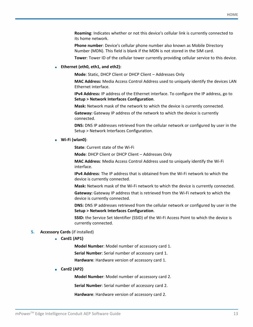
Roaming: Indicates whether or not this device's cellular link is currently connected toits home network.Phone number: Device's cellular phone number also known as Mobile DirectoryNumber (MDN). This field is blank if the MDN is not stored in the SIM card.Tower: Tower ID of the cellular tower currently providing cellular service to this device.
Ethernet (eth0, eth1, and eth2):
Mode: Static, DHCP Client or DHCP Client – Addresses OnlyMAC Address: Media Access Control Address used to uniquely identify the devices LANEthernet interface.IPv4 Address: IP address of the Ethernet interface. To configure the IP address, go toSetup > Network Interfaces Configuration.Mask: Network mask of the network to which the device is currently connected.Gateway: Gateway IP address of the network to which the device is currentlyconnected.DNS: DNS IP addresses retrieved from the cellular network or configured by user in theSetup > Network Interfaces Configuration.
Wi-Fi (wlan0):
State: Current state of the Wi-FiMode: DHCP Client or DHCP Client – Addresses OnlyMAC Address: Media Access Control Address used to uniquely identify the Wi-Fiinterface.IPv4 Address: The IP address that is obtained from the Wi-Fi network to which thedevice is currently connected.Mask: Network mask of the Wi-Fi network to which the device is currently connected.Gateway: Gateway IP address that is retrieved from the Wi-Fi network to which thedevice is currently connected.DNS: DNS IP addresses retrieved from the cellular network or configured by user in theSetup > Network Interfaces Configuration.SSID: the Service Set Identifier (SSID) of the Wi-Fi Access Point to which the device iscurrently connected.
5. Accessory Cards (if installed)Card1 (AP1)
Model Number: Model number of accessory card 1.Serial Number: Serial number of accessory card 1.Hardware: Hardware version of accessory card 1.
Card2 (AP2)
Model Number: Model number of accessory card 2.
Serial Number: Serial number of accessory card 2.
Hardware: Hardware version of accessory card 2.
LORAWAN
14 mPowerTM Edge Intelligence Conduit AEP Software Guide
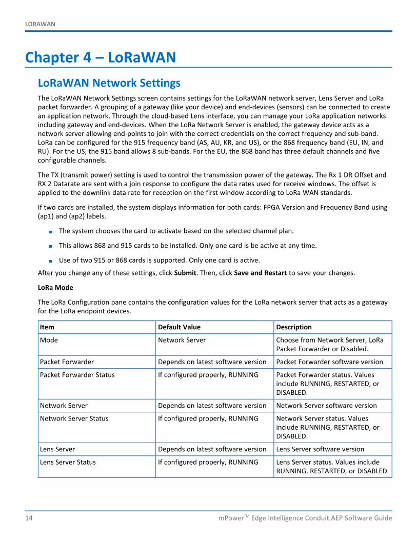
Chapter 4 – LoRaWANLoRaWAN Network SettingsThe LoRaWAN Network Settings screen contains settings for the LoRaWAN network server, Lens Server and LoRapacket forwarder. A grouping of a gateway (like your device) and end-devices (sensors) can be connected to createan application network. Through the cloud-based Lens interface, you can manage your LoRa application networksincluding gateway and end-devices. When the LoRa Network Server is enabled, the gateway device acts as anetwork server allowing end-points to join with the correct credentials on the correct frequency and sub-band.LoRa can be configured for the 915 frequency band (AS, AU, KR, and US), or the 868 frequency band (EU, IN, andRU). For the US, the 915 band allows 8 sub-bands. For the EU, the 868 band has three default channels and fiveconfigurable channels.
The TX (transmit power) setting is used to control the transmission power of the gateway. The Rx 1 DR Offset andRX 2 Datarate are sent with a join response to configure the data rates used for receive windows. The offset isapplied to the downlink data rate for reception on the first window according to LoRa WAN standards.
If two cards are installed, the system displays information for both cards: FPGA Version and Frequency Band using(ap1) and (ap2) labels.
The system chooses the card to activate based on the selected channel plan.
This allows 868 and 915 cards to be installed. Only one card is be active at any time.
Use of two 915 or 868 cards is supported. Only one card is active.
After you change any of these settings, click Submit. Then, click Save and Restart to save your changes.
LoRa Mode
The LoRa Configuration pane contains the configuration values for the LoRa network server that acts as a gatewayfor the LoRa endpoint devices.
Item Default Value Description
Mode Network Server Choose from Network Server, LoRaPacket Forwarder or Disabled.
Packet Forwarder Depends on latest software version Packet Forwarder software version
Packet Forwarder Status If configured properly, RUNNING Packet Forwarder status. Valuesinclude RUNNING, RESTARTED, orDISABLED.
Network Server Depends on latest software version Network Server software version
Network Server Status If configured properly, RUNNING Network Server status. Valuesinclude RUNNING, RESTARTED, orDISABLED.
Lens Server Depends on latest software version Lens Server software version
Lens Server Status If configured properly, RUNNING Lens Server status. Values includeRUNNING, RESTARTED, or DISABLED.
LORAWAN
mPowerTM Edge Intelligence Conduit AEP Software Guide 15
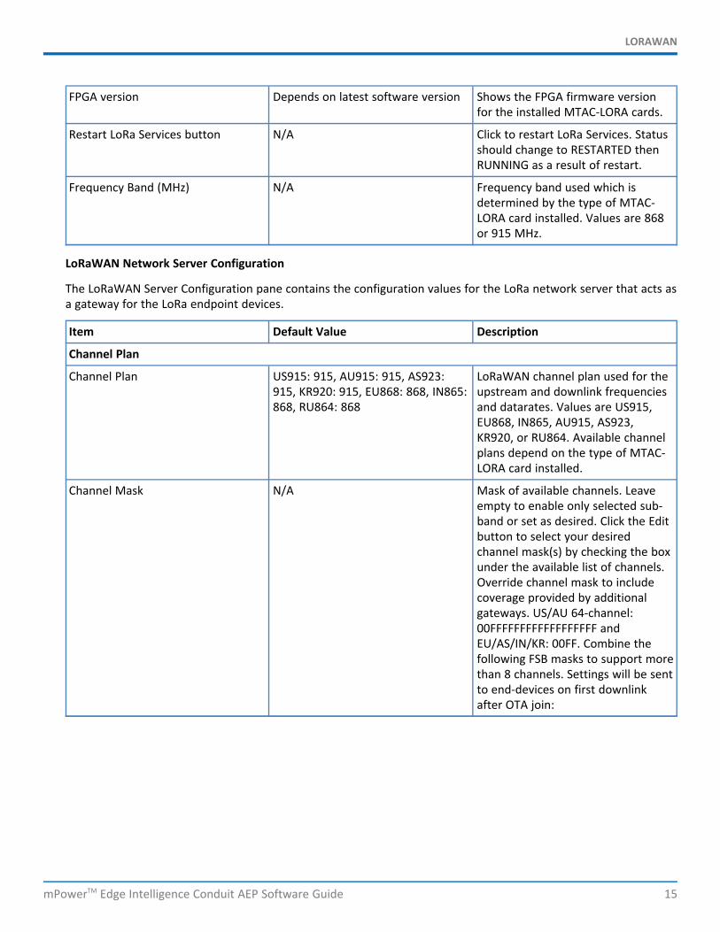
FPGA version Depends on latest software version Shows the FPGA firmware versionfor the installed MTAC-LORA cards.
Restart LoRa Services button N/A Click to restart LoRa Services. Statusshould change to RESTARTED thenRUNNING as a result of restart.
Frequency Band (MHz) N/A Frequency band used which isdetermined by the type of MTAC-LORA card installed. Values are 868or 915 MHz.
LoRaWAN Network Server Configuration
The LoRaWAN Server Configuration pane contains the configuration values for the LoRa network server that acts asa gateway for the LoRa endpoint devices.
Item Default Value Description
Channel Plan
Channel Plan US915: 915, AU915: 915, AS923:915, KR920: 915, EU868: 868, IN865:868, RU864: 868
LoRaWAN channel plan used for theupstream and downlink frequenciesand datarates. Values are US915,EU868, IN865, AU915, AS923,KR920, or RU864. Available channelplans depend on the type of MTAC-LORA card installed.
Channel Mask N/A Mask of available channels. Leaveempty to enable only selected sub-band or set as desired. Click the Editbutton to select your desiredchannel mask(s) by checking the boxunder the available list of channels.Override channel mask to includecoverage provided by additionalgateways. US/AU 64-channel:00FFFFFFFFFFFFFFFFFF andEU/AS/IN/KR: 00FF. Combine thefollowing FSB masks to support morethan 8 channels. Settings will be sentto end-devices on first downlinkafter OTA join:

LORAWAN
16 mPowerTM Edge Intelligence Conduit AEP Software Guide
FSB0:00FFFFFFFFFFFFFFFFFFFSB1:000100000000000000FFFSB2:0002000000000000FF00FSB3:00040000000000FF0000...FSB8:0080FF00000000000000FSB1 + FSB8:0081FF000000000000FF
Frequency Sub-Band 1 For US and AU only, 8 sub-bands areavailable.
Frequency Sub-Band 2 1 For US and AU only, 8 sub-bands areavailable (for extra LoRa Card).
Enable Diversity Unchecked Enable use of two LoRa cards.
Enable LBT Unchecked Enable Listen Before Talk. Note:Requires FPGA v33 or v61.
Max EIRP 20 Maximum uplink transmit power ofend-devices (in dBm)
Dwelltime Up 0 (no limit) Maximum uplink dwell-time forregion (ms). 0 : no limit and 1 : 400ms (depends on region).
Dwelltime Down 0 (no limit) Maximum downlink dwell-time forregion (ms). 0 : no limit and 1 : 400ms (depends on region).
Additional Channels Depends on channel plan selected A set of channels are configuredbased on this setting (MHz).Frequencies supported depends onchannel plan selected. v2.1Geolocation GW - default channelsmust be included in the configuredrange. The RU864 plan uses thefollowing channels when configuredwith the default settings of 0:
Radio 0: 868.9 MHz, 869.1 MHz
Radio 1: 864.1 MHz, 864.3 MHz,864.5 MHz, 864.7 MHz, 864.9MHz.

LORAWAN
mPowerTM Edge Intelligence Conduit AEP Software Guide 17
Additional Channels 2 Depends on channel plan selected A set of channels are configuredbased on this setting (MHz).Frequencies supported depends onchannel plan selected. v2.1Geolocation GW - Configurable forthe range within the entire band.TheRU864 plan will use the followingchannels when configured with thedefault settings of 0:
Radio 0: 868.9 MHz, 869.1 MHz
Radio 1: 864.1 MHz, 864.3 MHz,864.5 MHz, 864.7 MHz, 864.9MHz.
Duty Cycle Period 60 Number of minutes in slidingwindows for duty cycle restrictions(for EU only)
Class B Settings
Enable Beaconing Checked Enable beacon broadcasting.
Beacon Frequency 0 Beacon frequency (MHz).
Beacon Power 27 Beacon power (dBm). Select fromdrop-down: 0, 3, 6, 10, 11, 12, 13,14, 16, 20, 23, 24, 25, 26, or 27.
Disable Ping Slot Frequency Hopping Unchecked Disable frequency hopping onbeacons (only available in regionsthat support frequency hopping).
Ping Slot Frequency 0: uses the Channel Plan default Frequency to use on ping slots(MHz).
Ping Slot Datarate Default: automatically selects thedatarate for your region: US915 -DR8, AU915 - DR8, EU868 - DR3,IN865 - DR4, AS923 - DR3, KR920 -DR3, RU865 - DR3
Datarate to use on ping slots Selectfrom drop-down: DEFAULT, 8 -SF12BW500, 9 - SF11BW500, 10 -SF10BW500, 11 - SF9BW500, 12 -SF8BW500, or 13 - SF7BW500.
Info Descriptor 0 Info Descriptor of beacon. Selectfrom drop-down: 0, 1, or 2.
Beacon Latitude 0 GPS latitude of antenna specified byInfo Descriptor (degrees).
Beacon Longitude 0 GPS longitude of antenna specifiedby Info Descriptor (degrees).
Network
LORAWAN
18 mPowerTM Edge Intelligence Conduit AEP Software Guide
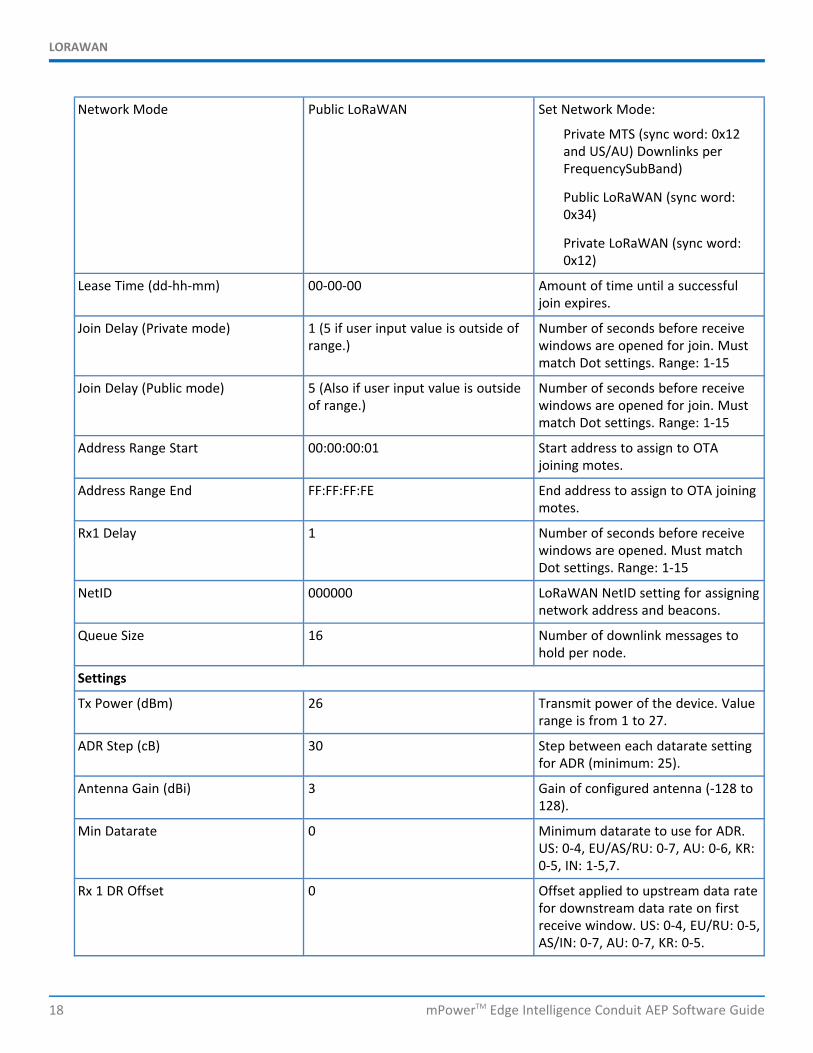
Network Mode Public LoRaWAN Set Network Mode:
Private MTS (sync word: 0x12and US/AU) Downlinks perFrequencySubBand)
Public LoRaWAN (sync word:0x34)
Private LoRaWAN (sync word:0x12)
Lease Time (dd-hh-mm) 00-00-00 Amount of time until a successfuljoin expires.
Join Delay (Private mode) 1 (5 if user input value is outside ofrange.)
Number of seconds before receivewindows are opened for join. Mustmatch Dot settings. Range: 1-15
Join Delay (Public mode) 5 (Also if user input value is outsideof range.)
Number of seconds before receivewindows are opened for join. Mustmatch Dot settings. Range: 1-15
Address Range Start 00:00:00:01 Start address to assign to OTAjoining motes.
Address Range End FF:FF:FF:FE End address to assign to OTA joiningmotes.
Rx1 Delay 1 Number of seconds before receivewindows are opened. Must matchDot settings. Range: 1-15
NetID 000000 LoRaWAN NetID setting for assigningnetwork address and beacons.
Queue Size 16 Number of downlink messages tohold per node.
Settings
Tx Power (dBm) 26 Transmit power of the device. Valuerange is from 1 to 27.
ADR Step (cB) 30 Step between each datarate settingfor ADR (minimum: 25).
Antenna Gain (dBi) 3 Gain of configured antenna (-128 to128).
Min Datarate 0 Minimum datarate to use for ADR.US: 0-4, EU/AS/RU: 0-7, AU: 0-6, KR:0-5, IN: 1-5,7.
Rx 1 DR Offset 0 Offset applied to upstream data ratefor downstream data rate on firstreceive window. US: 0-4, EU/RU: 0-5,AS/IN: 0-7, AU: 0-7, KR: 0-5.
LORAWAN
mPowerTM Edge Intelligence Conduit AEP Software Guide 19
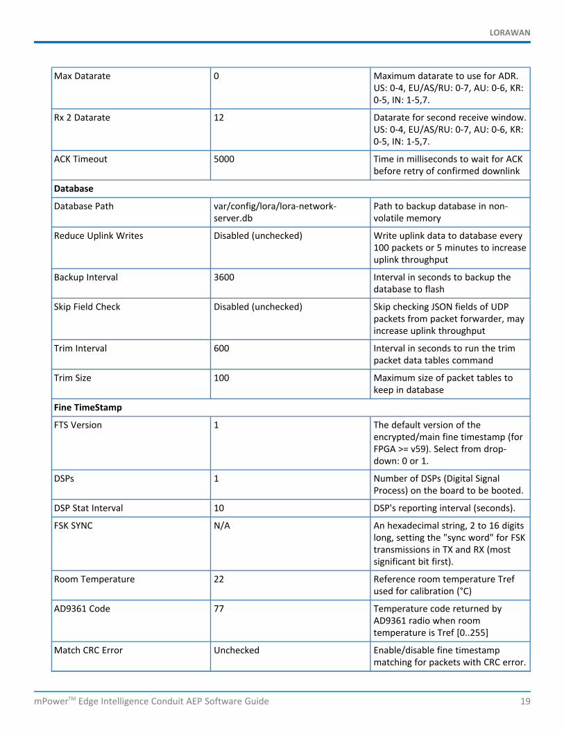
Max Datarate 0 Maximum datarate to use for ADR.US: 0-4, EU/AS/RU: 0-7, AU: 0-6, KR:0-5, IN: 1-5,7.
Rx 2 Datarate 12 Datarate for second receive window.US: 0-4, EU/AS/RU: 0-7, AU: 0-6, KR:0-5, IN: 1-5,7.
ACK Timeout 5000 Time in milliseconds to wait for ACKbefore retry of confirmed downlink
Database
Database Path var/config/lora/lora-network-server.db
Path to backup database in non-volatile memory
Reduce Uplink Writes Disabled (unchecked) Write uplink data to database every100 packets or 5 minutes to increaseuplink throughput
Backup Interval 3600 Interval in seconds to backup thedatabase to flash
Skip Field Check Disabled (unchecked) Skip checking JSON fields of UDPpackets from packet forwarder, mayincrease uplink throughput
Trim Interval 600 Interval in seconds to run the trimpacket data tables command
Trim Size 100 Maximum size of packet tables tokeep in database
Fine TimeStamp
FTS Version 1 The default version of theencrypted/main fine timestamp (forFPGA >= v59). Select from drop-down: 0 or 1.
DSPs 1 Number of DSPs (Digital SignalProcess) on the board to be booted.
DSP Stat Interval 10 DSP's reporting interval (seconds).
FSK SYNC N/A An hexadecimal string, 2 to 16 digitslong, setting the "sync word" for FSKtransmissions in TX and RX (mostsignificant bit first).
Room Temperature 22 Reference room temperature Trefused for calibration (°C)
AD9361 Code 77 Temperature code returned byAD9361 radio when roomtemperature is Tref [0..255]
Match CRC Error Unchecked Enable/disable fine timestampmatching for packets with CRC error.
LORAWAN
20 mPowerTM Edge Intelligence Conduit AEP Software Guide
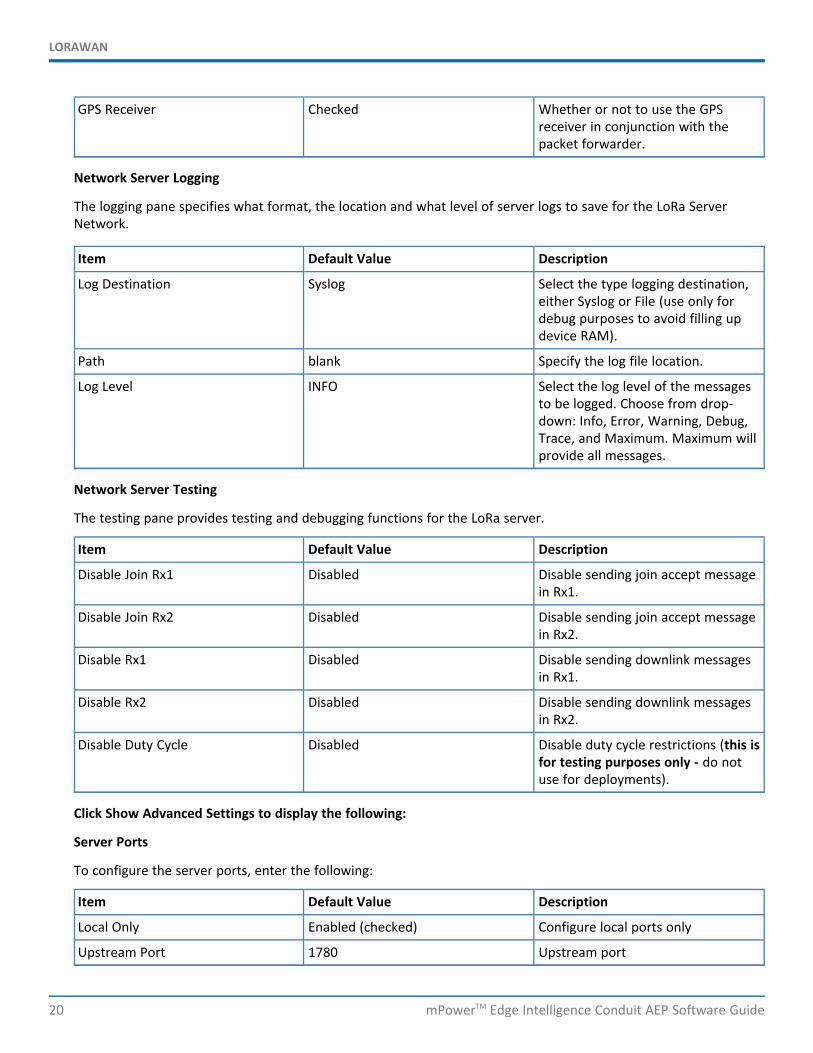
GPS Receiver Checked Whether or not to use the GPSreceiver in conjunction with thepacket forwarder.
Network Server Logging
The logging pane specifies what format, the location and what level of server logs to save for the LoRa ServerNetwork.
Item Default Value Description
Log Destination Syslog Select the type logging destination,either Syslog or File (use only fordebug purposes to avoid filling updevice RAM).
Path blank Specify the log file location.
Log Level INFO Select the log level of the messagesto be logged. Choose from drop-down: Info, Error, Warning, Debug,Trace, and Maximum. Maximum willprovide all messages.
Network Server Testing
The testing pane provides testing and debugging functions for the LoRa server.
Item Default Value Description
Disable Join Rx1 Disabled Disable sending join accept messagein Rx1.
Disable Join Rx2 Disabled Disable sending join accept messagein Rx2.
Disable Rx1 Disabled Disable sending downlink messagesin Rx1.
Disable Rx2 Disabled Disable sending downlink messagesin Rx2.
Disable Duty Cycle Disabled Disable duty cycle restrictions (this isfor testing purposes only - do notuse for deployments).
Click Show Advanced Settings to display the following:
Server Ports
To configure the server ports, enter the following:
Item Default Value Description
Local Only Enabled (checked) Configure local ports only
Upstream Port 1780 Upstream port
LORAWAN
mPowerTM Edge Intelligence Conduit AEP Software Guide 21
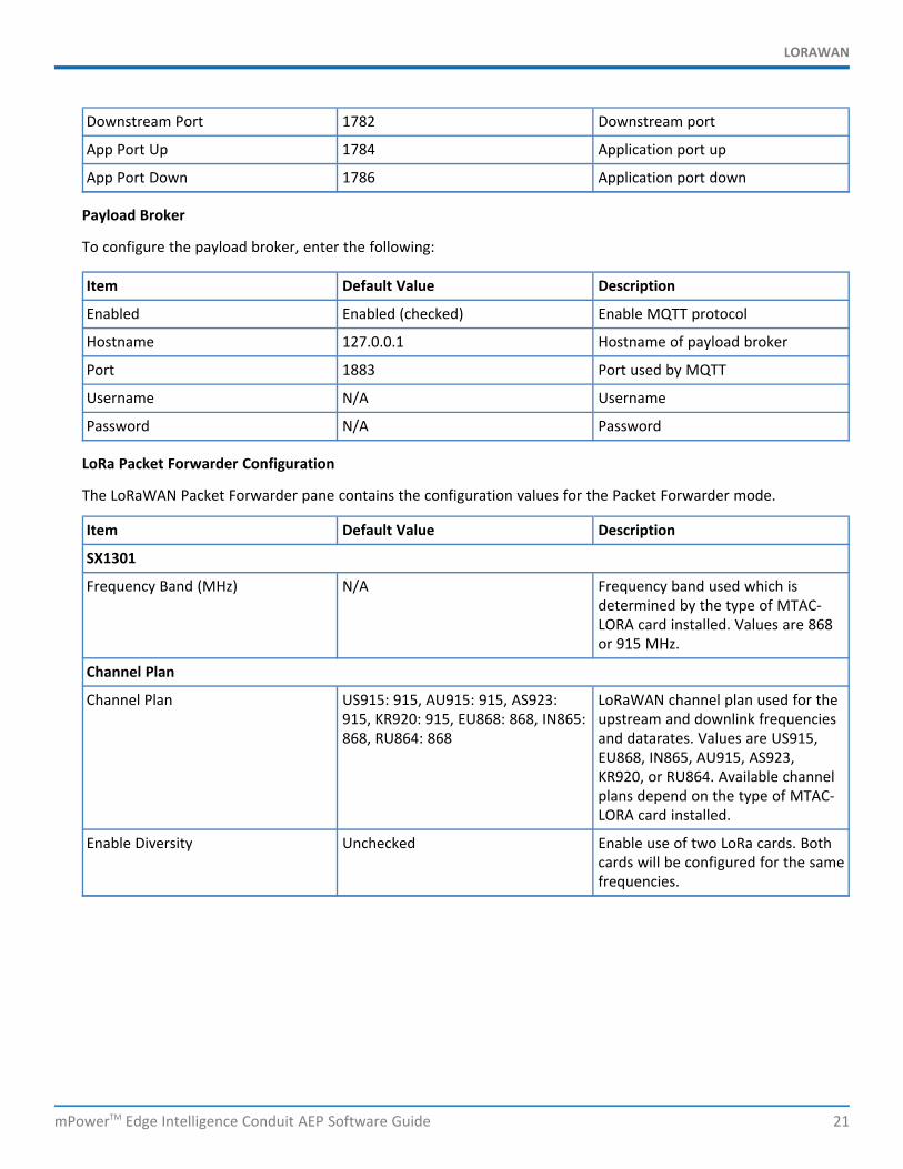
Downstream Port 1782 Downstream port
App Port Up 1784 Application port up
App Port Down 1786 Application port down
Payload Broker
To configure the payload broker, enter the following:
Item Default Value Description
Enabled Enabled (checked) Enable MQTT protocol
Hostname 127.0.0.1 Hostname of payload broker
Port 1883 Port used by MQTT
Username N/A Username
Password N/A Password
LoRa Packet Forwarder Configuration
The LoRaWAN Packet Forwarder pane contains the configuration values for the Packet Forwarder mode.
Item Default Value Description
SX1301
Frequency Band (MHz) N/A Frequency band used which isdetermined by the type of MTAC-LORA card installed. Values are 868or 915 MHz.
Channel Plan
Channel Plan US915: 915, AU915: 915, AS923:915, KR920: 915, EU868: 868, IN865:868, RU864: 868
LoRaWAN channel plan used for theupstream and downlink frequenciesand datarates. Values are US915,EU868, IN865, AU915, AS923,KR920, or RU864. Available channelplans depend on the type of MTAC-LORA card installed.
Enable Diversity Unchecked Enable use of two LoRa cards. Bothcards will be configured for the samefrequencies.
LORAWAN
22 mPowerTM Edge Intelligence Conduit AEP Software Guide
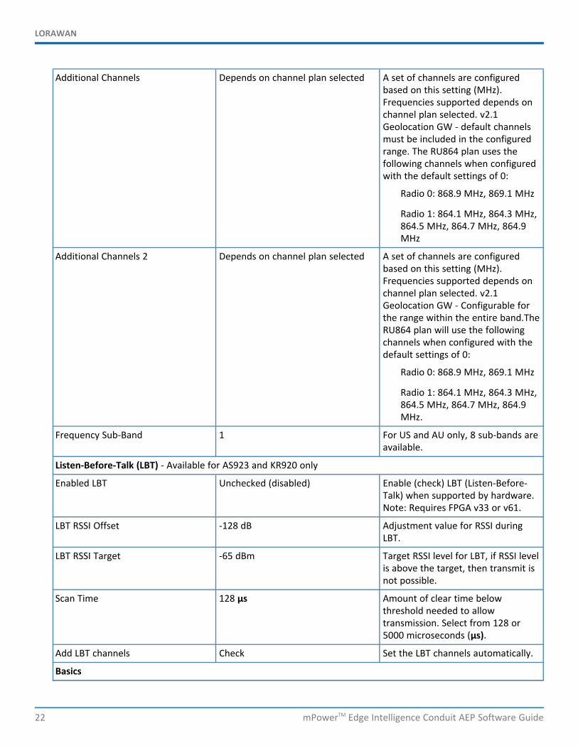
Additional Channels Depends on channel plan selected A set of channels are configuredbased on this setting (MHz).Frequencies supported depends onchannel plan selected. v2.1Geolocation GW - default channelsmust be included in the configuredrange. The RU864 plan uses thefollowing channels when configuredwith the default settings of 0:
Radio 0: 868.9 MHz, 869.1 MHz
Radio 1: 864.1 MHz, 864.3 MHz,864.5 MHz, 864.7 MHz, 864.9MHz
Additional Channels 2 Depends on channel plan selected A set of channels are configuredbased on this setting (MHz).Frequencies supported depends onchannel plan selected. v2.1Geolocation GW - Configurable forthe range within the entire band.TheRU864 plan will use the followingchannels when configured with thedefault settings of 0:
Radio 0: 868.9 MHz, 869.1 MHz
Radio 1: 864.1 MHz, 864.3 MHz,864.5 MHz, 864.7 MHz, 864.9MHz.
Frequency Sub-Band 1 For US and AU only, 8 sub-bands areavailable.
Listen-Before-Talk (LBT) - Available for AS923 and KR920 only
Enabled LBT Unchecked (disabled) Enable (check) LBT (Listen-Before-Talk) when supported by hardware.Note: Requires FPGA v33 or v61.
LBT RSSI Offset -128 dB Adjustment value for RSSI duringLBT.
LBT RSSI Target -65 dBm Target RSSI level for LBT, if RSSI levelis above the target, then transmit isnot possible.
Scan Time 128 μs Amount of clear time belowthreshold needed to allowtransmission. Select from 128 or5000 microseconds (μs).
Add LBT channels Check Set the LBT channels automatically.
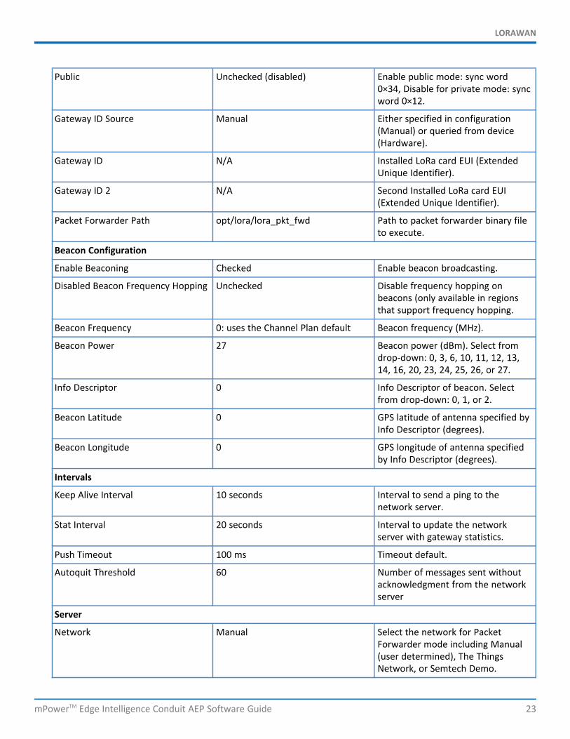
Basics
LORAWAN
mPowerTM Edge Intelligence Conduit AEP Software Guide 23
Public Unchecked (disabled) Enable public mode: sync word0×34, Disable for private mode: syncword 0×12.
Gateway ID Source Manual Either specified in configuration(Manual) or queried from device(Hardware).
Gateway ID N/A Installed LoRa card EUI (ExtendedUnique Identifier).
Gateway ID 2 N/A Second Installed LoRa card EUI(Extended Unique Identifier).
Packet Forwarder Path opt/lora/lora_pkt_fwd Path to packet forwarder binary fileto execute.
Beacon Configuration
Enable Beaconing Checked Enable beacon broadcasting.
Disabled Beacon Frequency Hopping Unchecked Disable frequency hopping onbeacons (only available in regionsthat support frequency hopping.
Beacon Frequency 0: uses the Channel Plan default Beacon frequency (MHz).
Beacon Power 27 Beacon power (dBm). Select fromdrop-down: 0, 3, 6, 10, 11, 12, 13,14, 16, 20, 23, 24, 25, 26, or 27.
Info Descriptor 0 Info Descriptor of beacon. Selectfrom drop-down: 0, 1, or 2.
Beacon Latitude 0 GPS latitude of antenna specified byInfo Descriptor (degrees).
Beacon Longitude 0 GPS longitude of antenna specifiedby Info Descriptor (degrees).
Intervals
Keep Alive Interval 10 seconds Interval to send a ping to thenetwork server.
Stat Interval 20 seconds Interval to update the networkserver with gateway statistics.
Push Timeout 100 ms Timeout default.
Autoquit Threshold 60 Number of messages sent withoutacknowledgment from the networkserver
Server
Network Manual Select the network for PacketForwarder mode including Manual(user determined), The ThingsNetwork, or Semtech Demo.
LORAWAN
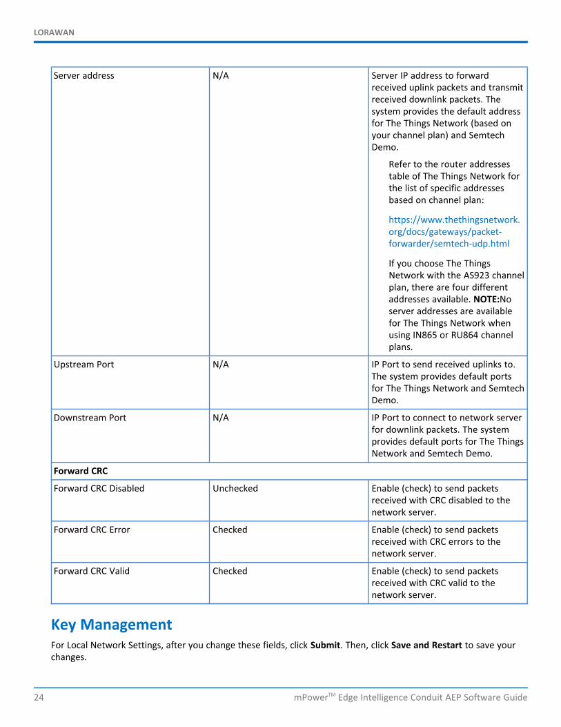
24 mPowerTM Edge Intelligence Conduit AEP Software Guide
Server address N/A Server IP address to forwardreceived uplink packets and transmitreceived downlink packets. Thesystem provides the default addressfor The Things Network (based onyour channel plan) and SemtechDemo.
Refer to the router addressestable of The Things Network forthe list of specific addressesbased on channel plan:
https://www.thethingsnetwork.org/docs/gateways/packet-forwarder/semtech-udp.html
If you choose The ThingsNetwork with the AS923 channelplan, there are four differentaddresses available. NOTE:Noserver addresses are availablefor The Things Network whenusing IN865 or RU864 channelplans.
Upstream Port N/A IP Port to send received uplinks to.The system provides default portsfor The Things Network and SemtechDemo.
Downstream Port N/A IP Port to connect to network serverfor downlink packets. The systemprovides default ports for The ThingsNetwork and Semtech Demo.
Forward CRC
Forward CRC Disabled Unchecked Enable (check) to send packetsreceived with CRC disabled to thenetwork server.
Forward CRC Error Checked Enable (check) to send packetsreceived with CRC errors to thenetwork server.
Forward CRC Valid Checked Enable (check) to send packetsreceived with CRC valid to thenetwork server.
Key ManagementFor Local Network Settings, after you change these fields, click Submit. Then, click Save and Restart to save yourchanges.
LORAWAN
mPowerTM Edge Intelligence Conduit AEP Software Guide 25
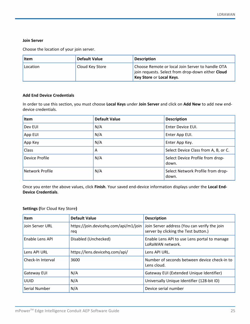
Join Server
Choose the location of your join server.
Item Default Value Description
Location Cloud Key Store Choose Remote or local Join Server to handle OTAjoin requests. Select from drop-down either CloudKey Store or Local Keys.
Add End Device Credentials
In order to use this section, you must choose Local Keys under Join Server and click on Add New to add new end-device credentials.
Item Default Value Description
Dev EUI N/A Enter Device EUI.
App EUI N/A Enter App EUI.
App Key N/A Enter App Key.
Class A Select Device Class from A, B, or C.
Device Profile N/A Select Device Profile from drop-down.
Network Profile N/A Select Network Profile from drop-down.
Once you enter the above values, click Finish. Your saved end-device information displays under the Local End-Device Credentials.
Settings (for Cloud Key Store)
Item Default Value Description
Join Server URL https://join.devicehq.com/api/m1/joinreq
Join Server address (You can verify the joinserver by clicking the Test button.)
Enable Lens API Disabled (Unchecked) Enable Lens API to use Lens portal to manageLoRaWAN network.
Lens API URL https://lens.devicehq.com/api/ Lens API URL.
Check-In Interval 3600 Number of seconds between device check-in toLens cloud.
Gateway EUI N/A Gateway EUI (Extended Unique Identifier)
UUID N/A Universally Unique Identifier (128-bit ID)
Serial Number N/A Device serial number
LORAWAN
26 mPowerTM Edge Intelligence Conduit AEP Software Guide
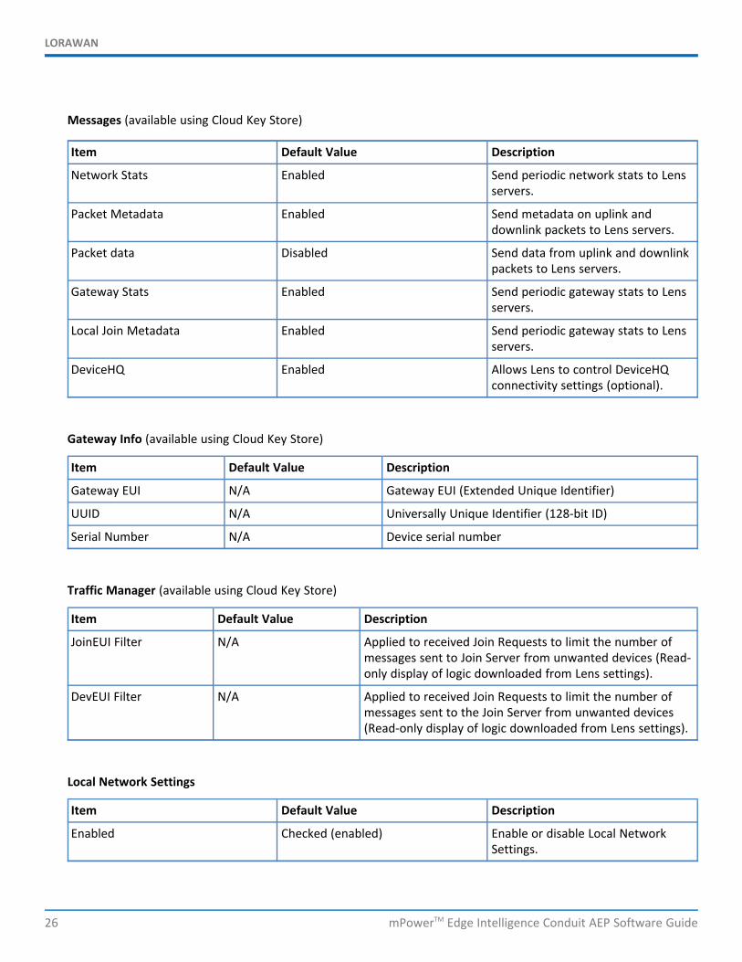
Messages (available using Cloud Key Store)
Item Default Value Description
Network Stats Enabled Send periodic network stats to Lensservers.
Packet Metadata Enabled Send metadata on uplink anddownlink packets to Lens servers.
Packet data Disabled Send data from uplink and downlinkpackets to Lens servers.
Gateway Stats Enabled Send periodic gateway stats to Lensservers.
Local Join Metadata Enabled Send periodic gateway stats to Lensservers.
DeviceHQ Enabled Allows Lens to control DeviceHQconnectivity settings (optional).
Gateway Info (available using Cloud Key Store)
Item Default Value Description
Gateway EUI N/A Gateway EUI (Extended Unique Identifier)
UUID N/A Universally Unique Identifier (128-bit ID)
Serial Number N/A Device serial number
Traffic Manager (available using Cloud Key Store)
Item Default Value Description
JoinEUI Filter N/A Applied to received Join Requests to limit the number ofmessages sent to Join Server from unwanted devices (Read-only display of logic downloaded from Lens settings).
DevEUI Filter N/A Applied to received Join Requests to limit the number ofmessages sent to the Join Server from unwanted devices(Read-only display of logic downloaded from Lens settings).
Local Network Settings
Item Default Value Description
Enabled Checked (enabled) Enable or disable Local NetworkSettings.
LORAWAN
mPowerTM Edge Intelligence Conduit AEP Software Guide 27
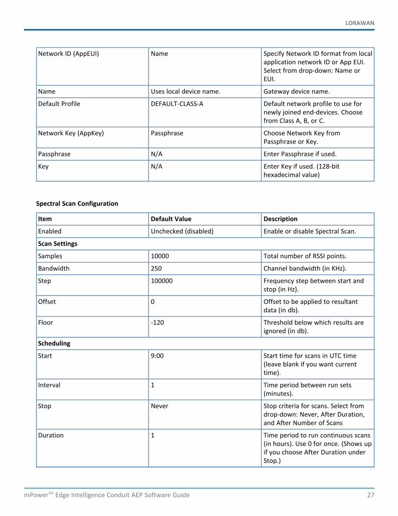
Network ID (AppEUI) Name Specify Network ID format from localapplication network ID or App EUI.Select from drop-down: Name orEUI.
Name Uses local device name. Gateway device name.
Default Profile DEFAULT-CLASS-A Default network profile to use fornewly joined end-devices. Choosefrom Class A, B, or C.
Network Key (AppKey) Passphrase Choose Network Key fromPassphrase or Key.
Passphrase N/A Enter Passphrase if used.
Key N/A Enter Key if used. (128-bithexadecimal value)
Spectral Scan Configuration
Item Default Value Description
Enabled Unchecked (disabled) Enable or disable Spectral Scan.
Scan Settings
Samples 10000 Total number of RSSI points.
Bandwidth 250 Channel bandwidth (in KHz).
Step 100000 Frequency step between start andstop (in Hz).
Offset 0 Offset to be applied to resultantdata (in db).
Floor -120 Threshold below which results areignored (in db).
Scheduling
Start 9:00 Start time for scans in UTC time(leave blank if you want currenttime).
Interval 1 Time period between run sets(minutes).
Stop Never Stop criteria for scans. Select fromdrop-down: Never, After Duration,and After Number of Scans
Duration 1 Time period to run continuous scans(in hours). Use 0 for once. (Shows upif you choose After Duration underStop.)
LORAWAN
28 mPowerTM Edge Intelligence Conduit AEP Software Guide
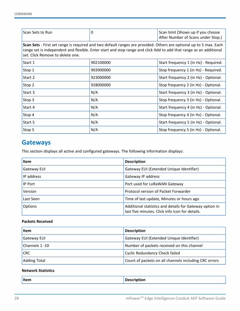
Scan Sets to Run 0 Scan limit (Shows up if you chooseAfter Number of Scans under Stop.)
Scan Sets - First set range is required and two default ranges are provided. Others are optional up to 5 max. Eachrange set is independent and flexible. Enter start and stop range and click Add to add that range as an additionalset. Click Remove to delete one.
Start 1 902100000 Start frequency 1 (in Hz) - Required.
Stop 1 903900000 Stop frequency 1 (in Hz) - Required.
Start 2 923000000 Start frequency 2 (in Hz) - Optional.
Stop 2 928000000 Stop frequency 2 (in Hz) - Optional.
Start 3 N/A Start frequency 3 (in Hz) - Optional.
Stop 3 N/A Stop frequency 3 (in Hz) - Optional.
Start 4 N/A Start frequency 4 (in Hz) - Optional.
Stop 4 N/A Stop frequency 4 (in Hz) - Optional.
Start 5 N/A Start frequency 5 (in Hz) - Optional.
Stop 5 N/A Stop frequency 5 (in Hz) - Optional.
GatewaysThis section displays all active and configured gateways. The following information displays:
Item Description
Gateway EUI Gateway EUI (Extended Unique Identifier)
IP address Gateway IP address
IP Port Port used for LoRaWAN Gateway
Version Protocol version of Packet Forwarder
Last Seen Time of last update, Minutes or hours ago
Options Additional statistics and details for Gateway option inlast five minutes. Click info icon for details.
Packets Received
Item Description
Gateway EUI Gateway EUI (Extended Unique Identifier)
Channels 1 -10 Number of packets received on this channel
CRC Cyclic Redundancy Check failed
Adding Total Count of packets on all channels including CRC errors
Network Statistics
Item Description
LORAWAN
mPowerTM Edge Intelligence Conduit AEP Software Guide 29
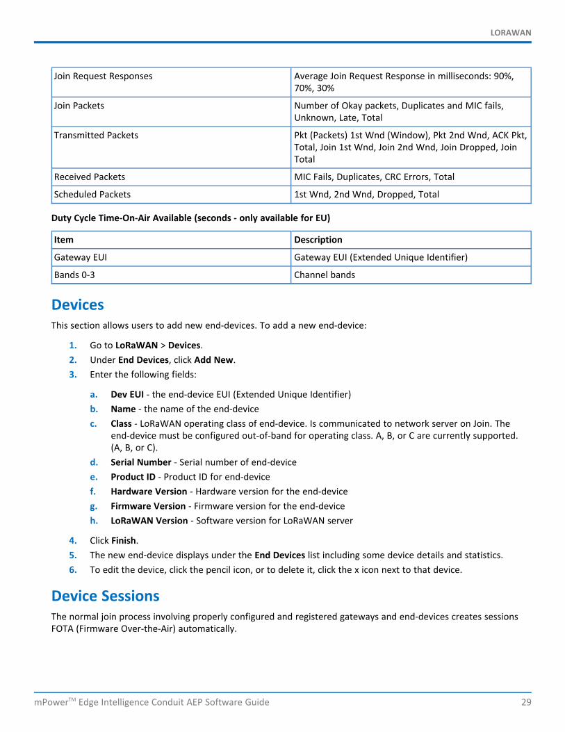
Join Request Responses Average Join Request Response in milliseconds: 90%,70%, 30%
Join Packets Number of Okay packets, Duplicates and MIC fails,Unknown, Late, Total
Transmitted Packets Pkt (Packets) 1st Wnd (Window), Pkt 2nd Wnd, ACK Pkt,Total, Join 1st Wnd, Join 2nd Wnd, Join Dropped, JoinTotal
Received Packets MIC Fails, Duplicates, CRC Errors, Total
Scheduled Packets 1st Wnd, 2nd Wnd, Dropped, Total
Duty Cycle Time-On-Air Available (seconds - only available for EU)
Item Description
Gateway EUI Gateway EUI (Extended Unique Identifier)
Bands 0-3 Channel bands
DevicesThis section allows users to add new end-devices. To add a new end-device:
1. Go to LoRaWAN > Devices.2. Under End Devices, click Add New.3. Enter the following fields:
a. Dev EUI - the end-device EUI (Extended Unique Identifier)b. Name - the name of the end-devicec. Class - LoRaWAN operating class of end-device. Is communicated to network server on Join. The
end-device must be configured out-of-band for operating class. A, B, or C are currently supported.(A, B, or C).
d. Serial Number - Serial number of end-devicee. Product ID - Product ID for end-devicef. Hardware Version - Hardware version for the end-deviceg. Firmware Version - Firmware version for the end-deviceh. LoRaWAN Version - Software version for LoRaWAN server
4. Click Finish.5. The new end-device displays under the End Devices list including some device details and statistics.6. To edit the device, click the pencil icon, or to delete it, click the x icon next to that device.
Device SessionsThe normal join process involving properly configured and registered gateways and end-devices creates sessionsFOTA (Firmware Over-the-Air) automatically.
LORAWAN
30 mPowerTM Edge Intelligence Conduit AEP Software Guide
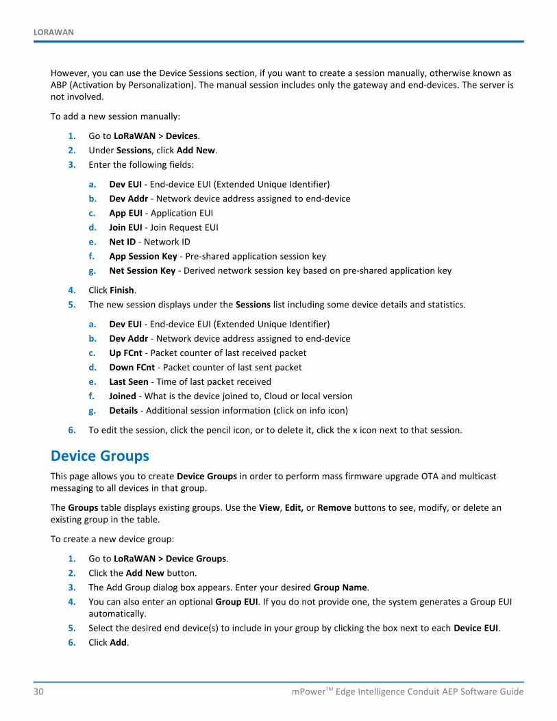
However, you can use the Device Sessions section, if you want to create a session manually, otherwise known asABP (Activation by Personalization). The manual session includes only the gateway and end-devices. The server isnot involved.
To add a new session manually:
1. Go to LoRaWAN > Devices.2. Under Sessions, click Add New.3. Enter the following fields:
a. Dev EUI - End-device EUI (Extended Unique Identifier)b. Dev Addr - Network device address assigned to end-devicec. App EUI - Application EUId. Join EUI - Join Request EUIe. Net ID - Network IDf. App Session Key - Pre-shared application session keyg. Net Session Key - Derived network session key based on pre-shared application key
4. Click Finish.5. The new session displays under the Sessions list including some device details and statistics.
a. Dev EUI - End-device EUI (Extended Unique Identifier)b. Dev Addr - Network device address assigned to end-devicec. Up FCnt - Packet counter of last received packetd. Down FCnt - Packet counter of last sent packete. Last Seen - Time of last packet receivedf. Joined - What is the device joined to, Cloud or local versiong. Details - Additional session information (click on info icon)
6. To edit the session, click the pencil icon, or to delete it, click the x icon next to that session.
Device GroupsThis page allows you to create Device Groups in order to perform mass firmware upgrade OTA and multicastmessaging to all devices in that group.
The Groups table displays existing groups. Use the View, Edit, or Remove buttons to see, modify, or delete anexisting group in the table.
To create a new device group:
1. Go to LoRaWAN > Device Groups.2. Click the Add New button.3. The Add Group dialog box appears. Enter your desired Group Name.4. You can also enter an optional Group EUI. If you do not provide one, the system generates a Group EUI
automatically.5. Select the desired end device(s) to include in your group by clicking the box next to each Device EUI.6. Click Add.
LORAWAN
mPowerTM Edge Intelligence Conduit AEP Software Guide 31
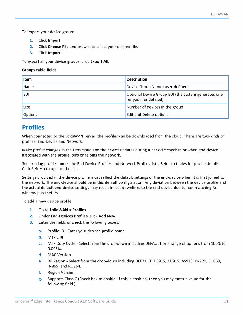
To import your device group:
1. Click Import.2. Click Choose File and browse to select your desired file.3. Click Import.
To export all your device groups, click Export All.
Groups table fields
Item Description
Name Device Group Name (user-defined)
EUI Optional Device Group EUI (the system generates onefor you if undefined)
Size Number of devices in the group
Options Edit and Delete options
ProfilesWhen connected to the LoRaWAN server, the profiles can be downloaded from the cloud. There are two-kinds ofprofiles: End-Device and Network.
Make profile changes in the Lens cloud and the device updates during a periodic check-in or when end-deviceassociated with the profile joins or rejoins the network.
See existing profiles under the End-Device Profiles and Network Profiles lists. Refer to tables for profile details.Click Refresh to update the list.
Settings provided in the device profile must reflect the default settings of the end-device when it is first joined tothe network. The end-device should be in this default configuration. Any deviation between the device profile andthe actual default end-device settings may result in lost downlinks to the end-device due to non-matching Rxwindow parameters.
To add a new device profile:
1. Go to LoRaWAN > Profiles.2. Under End-Devices Profiles, click Add New.3. Enter the fields or check the following boxes:
a. Profile ID - Enter your desired profile name.b. Max EIRPc. Max Duty Cycle - Select from the drop-down including DEFAULT or a range of options from 100% to
0.003%.d. MAC Version.e. RF Region - Select from the drop-down including DEFAULT, US915, AU915, AS923, KR920, EU868,
IN865, and RU864.f. Region Version.g. Supports Class C (Check box to enable. If this is enabled, then you may enter a value for the
following field.)
LORAWAN
32 mPowerTM Edge Intelligence Conduit AEP Software Guide
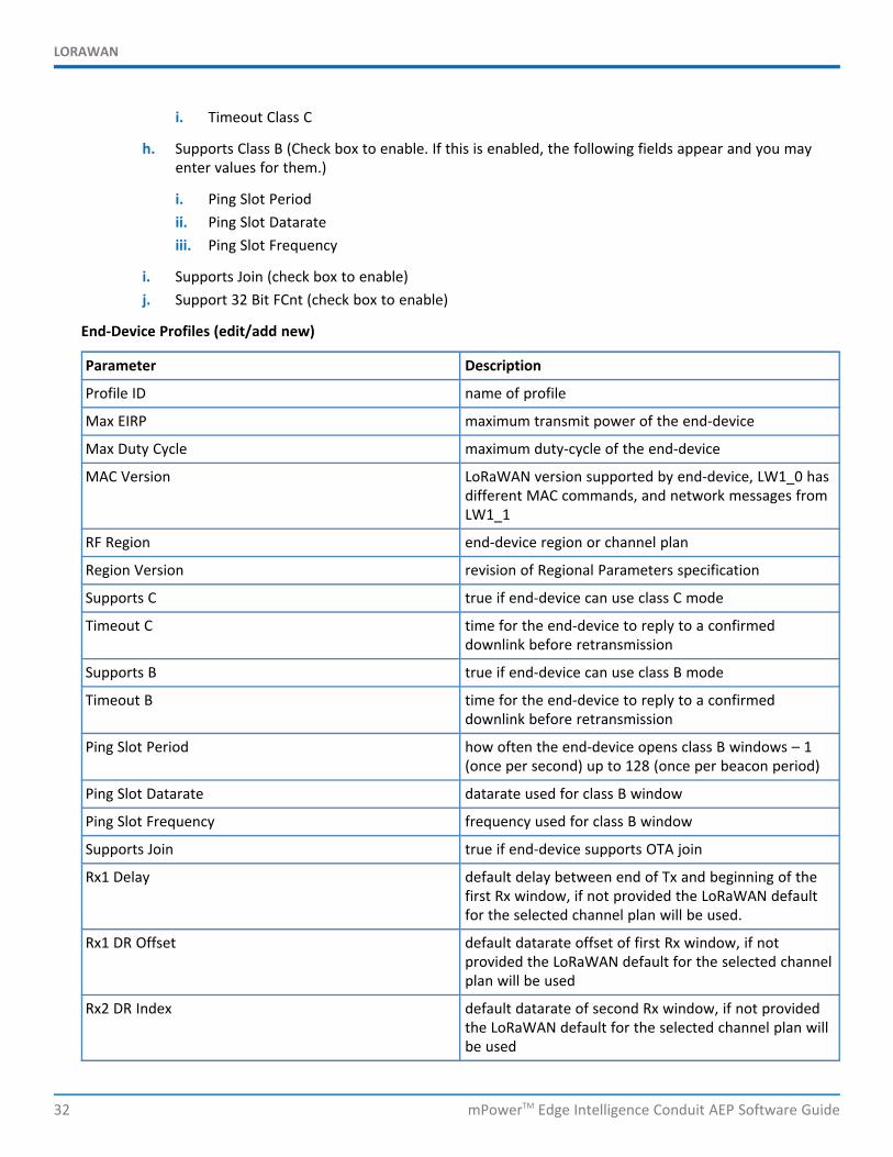
i. Timeout Class C
h. Supports Class B (Check box to enable. If this is enabled, the following fields appear and you mayenter values for them.)
i. Ping Slot Periodii. Ping Slot Datarateiii. Ping Slot Frequency
i. Supports Join (check box to enable)j. Support 32 Bit FCnt (check box to enable)
End-Device Profiles (edit/add new)
Parameter Description
Profile ID name of profile
Max EIRP maximum transmit power of the end-device
Max Duty Cycle maximum duty-cycle of the end-device
MAC Version LoRaWAN version supported by end-device, LW1_0 hasdifferent MAC commands, and network messages fromLW1_1
RF Region end-device region or channel plan
Region Version revision of Regional Parameters specification
Supports C true if end-device can use class C mode
Timeout C time for the end-device to reply to a confirmeddownlink before retransmission
Supports B true if end-device can use class B mode
Timeout B time for the end-device to reply to a confirmeddownlink before retransmission
Ping Slot Period how often the end-device opens class B windows – 1(once per second) up to 128 (once per beacon period)
Ping Slot Datarate datarate used for class B window
Ping Slot Frequency frequency used for class B window
Supports Join true if end-device supports OTA join
Rx1 Delay default delay between end of Tx and beginning of thefirst Rx window, if not provided the LoRaWAN defaultfor the selected channel plan will be used.
Rx1 DR Offset default datarate offset of first Rx window, if notprovided the LoRaWAN default for the selected channelplan will be used
Rx2 DR Index default datarate of second Rx window, if not providedthe LoRaWAN default for the selected channel plan willbe used
LORAWAN
mPowerTM Edge Intelligence Conduit AEP Software Guide 33
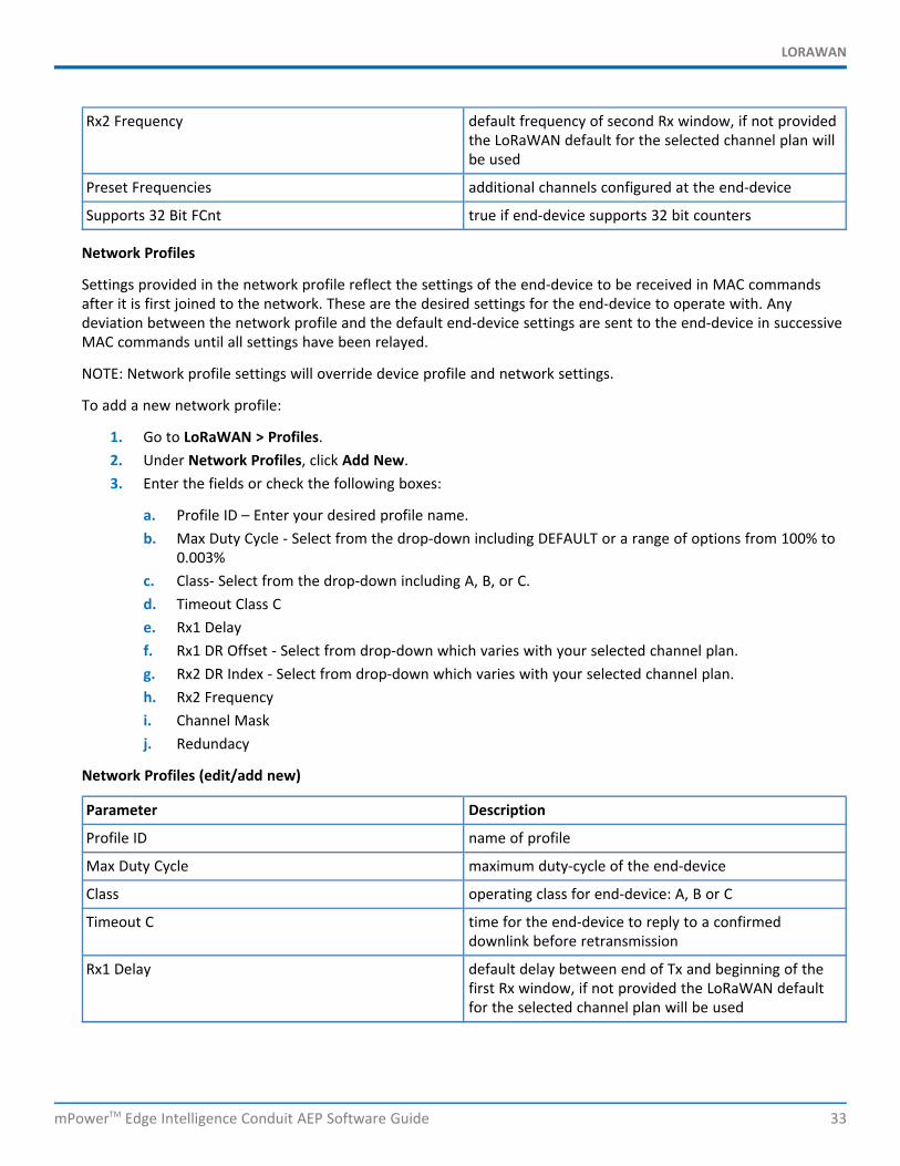
Rx2 Frequency default frequency of second Rx window, if not providedthe LoRaWAN default for the selected channel plan willbe used
Preset Frequencies additional channels configured at the end-device
Supports 32 Bit FCnt true if end-device supports 32 bit counters
Network Profiles
Settings provided in the network profile reflect the settings of the end-device to be received in MAC commandsafter it is first joined to the network. These are the desired settings for the end-device to operate with. Anydeviation between the network profile and the default end-device settings are sent to the end-device in successiveMAC commands until all settings have been relayed.
NOTE: Network profile settings will override device profile and network settings.
To add a new network profile:
1. Go to LoRaWAN > Profiles.2. Under Network Profiles, click Add New.3. Enter the fields or check the following boxes:
a. Profile ID – Enter your desired profile name.b. Max Duty Cycle - Select from the drop-down including DEFAULT or a range of options from 100% to
0.003%c. Class- Select from the drop-down including A, B, or C.d. Timeout Class Ce. Rx1 Delayf. Rx1 DR Offset - Select from drop-down which varies with your selected channel plan.g. Rx2 DR Index - Select from drop-down which varies with your selected channel plan.h. Rx2 Frequencyi. Channel Maskj. Redundacy
Network Profiles (edit/add new)
Parameter Description
Profile ID name of profile
Max Duty Cycle maximum duty-cycle of the end-device
Class operating class for end-device: A, B or C
Timeout C time for the end-device to reply to a confirmeddownlink before retransmission
Rx1 Delay default delay between end of Tx and beginning of thefirst Rx window, if not provided the LoRaWAN defaultfor the selected channel plan will be used
LORAWAN
34 mPowerTM Edge Intelligence Conduit AEP Software Guide
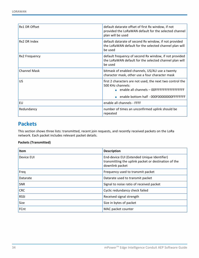
Rx1 DR Offset default datarate offset of first Rx window, if notprovided the LoRaWAN default for the selected channelplan will be used
Rx2 DR Index default datarate of second Rx window, if not providedthe LoRaWAN default for the selected channel plan willbe used
Rx2 Frequency default frequency of second Rx window, if not providedthe LoRaWAN default for the selected channel plan willbe used
Channel Mask bitmask of enabled channels, US/AU use a twentycharacter mask, other use a four character mask
US first 2 characters are not used, the next two control the500 KHz channels:
enable all channels – 00FFFFFFFFFFFFFFFFFF
enable bottom half - 000F00000000FFFFFFFF
EU enable all channels - FFFF
Redundancy number of times an unconfirmed uplink should berepeated
PacketsThis section shows three lists: transmitted, recent join requests, and recently received packets on the LoRanetwork. Each packet includes relevant packet details.
Packets (Transmitted)
Item Description
Device EUI End-device EUI (Extended Unique Identifier)transmitting the uplink packet or destination of thedownlink packet
Freq Frequency used to transmit packet
Datarate Datarate used to transmit packet
SNR Signal to noise ratio of received packet
CRC Cyclic redundancy check failed
RSSI Received signal strength
Size Size in bytes of packet
FCnt MAC packet counter
LORAWAN
mPowerTM Edge Intelligence Conduit AEP Software Guide 35
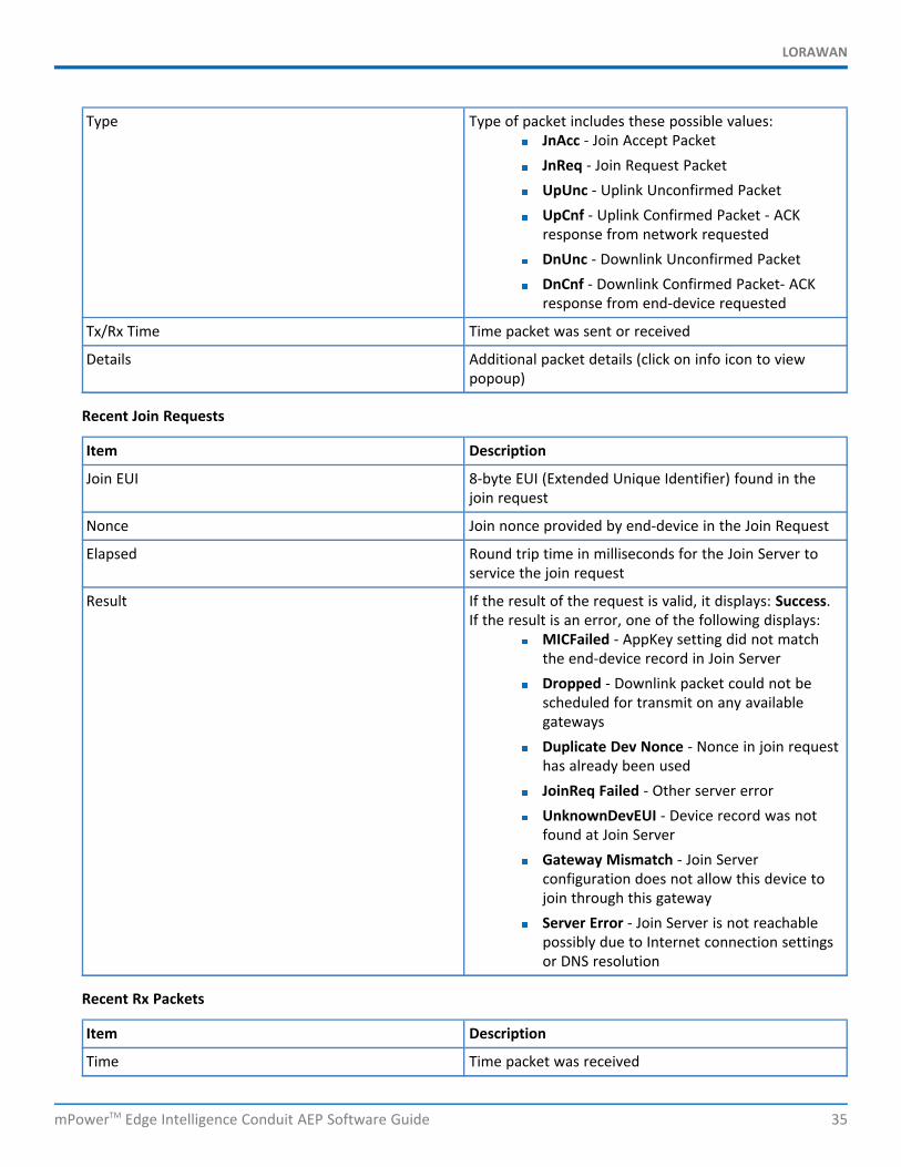
Type Type of packet includes these possible values:JnAcc - Join Accept PacketJnReq - Join Request PacketUpUnc - Uplink Unconfirmed PacketUpCnf - Uplink Confirmed Packet - ACKresponse from network requestedDnUnc - Downlink Unconfirmed PacketDnCnf - Downlink Confirmed Packet- ACKresponse from end-device requested
Tx/Rx Time Time packet was sent or received
Details Additional packet details (click on info icon to viewpopoup)
Recent Join Requests
Item Description
Join EUI 8-byte EUI (Extended Unique Identifier) found in thejoin request
Nonce Join nonce provided by end-device in the Join Request
Elapsed Round trip time in milliseconds for the Join Server toservice the join request
Result If the result of the request is valid, it displays: Success.If the result is an error, one of the following displays:
MICFailed - AppKey setting did not matchthe end-device record in Join ServerDropped - Downlink packet could not bescheduled for transmit on any availablegatewaysDuplicate Dev Nonce - Nonce in join requesthas already been usedJoinReq Failed - Other server errorUnknownDevEUI - Device record was notfound at Join ServerGateway Mismatch - Join Serverconfiguration does not allow this device tojoin through this gatewayServer Error - Join Server is not reachablepossibly due to Internet connection settingsor DNS resolution
Recent Rx Packets
Item Description
Time Time packet was received
LORAWAN
36 mPowerTM Edge Intelligence Conduit AEP Software Guide
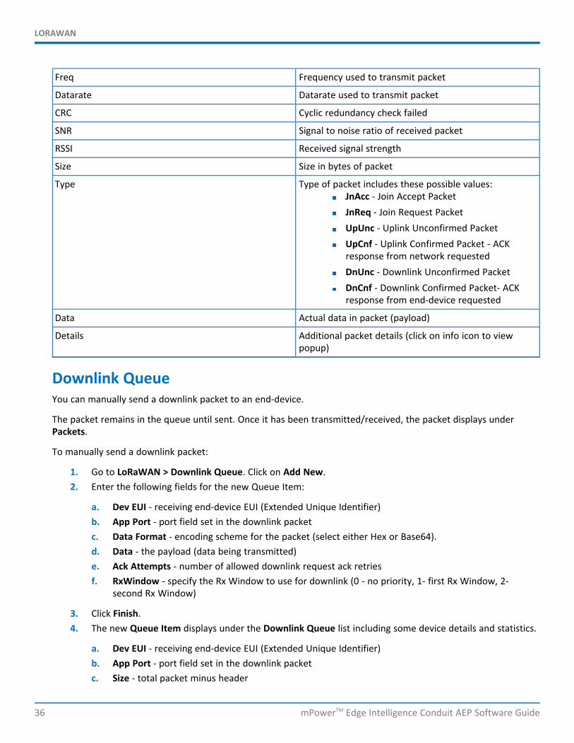
Freq Frequency used to transmit packet
Datarate Datarate used to transmit packet
CRC Cyclic redundancy check failed
SNR Signal to noise ratio of received packet
RSSI Received signal strength
Size Size in bytes of packet
Type Type of packet includes these possible values:JnAcc - Join Accept PacketJnReq - Join Request PacketUpUnc - Uplink Unconfirmed PacketUpCnf - Uplink Confirmed Packet - ACKresponse from network requestedDnUnc - Downlink Unconfirmed PacketDnCnf - Downlink Confirmed Packet- ACKresponse from end-device requested
Data Actual data in packet (payload)
Details Additional packet details (click on info icon to viewpopup)
Downlink QueueYou can manually send a downlink packet to an end-device.
The packet remains in the queue until sent. Once it has been transmitted/received, the packet displays underPackets.
To manually send a downlink packet:
1. Go to LoRaWAN > Downlink Queue. Click on Add New.2. Enter the following fields for the new Queue Item:
a. Dev EUI - receiving end-device EUI (Extended Unique Identifier)b. App Port - port field set in the downlink packetc. Data Format - encoding scheme for the packet (select either Hex or Base64).d. Data - the payload (data being transmitted)e. Ack Attempts - number of allowed downlink request ack retriesf. RxWindow - specify the Rx Window to use for downlink (0 - no priority, 1- first Rx Window, 2-
second Rx Window)
3. Click Finish.4. The new Queue Item displays under the Downlink Queue list including some device details and statistics.
a. Dev EUI - receiving end-device EUI (Extended Unique Identifier)b. App Port - port field set in the downlink packetc. Size - total packet minus header
LORAWAN
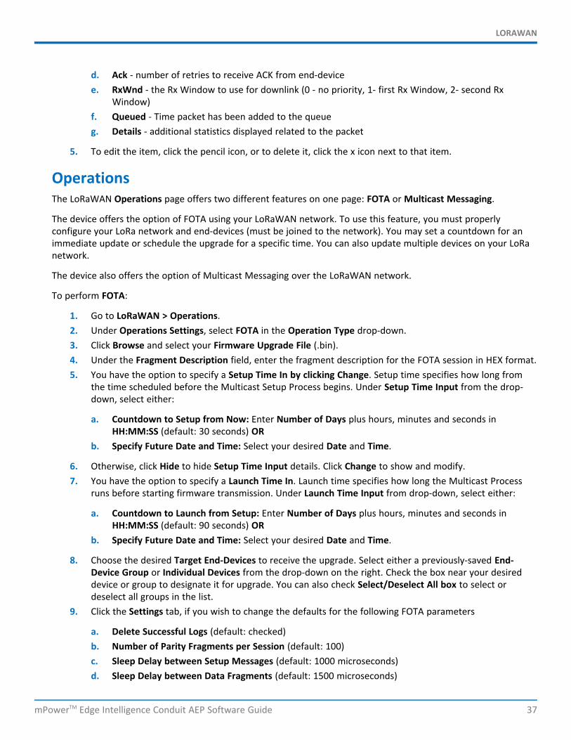
mPowerTM Edge Intelligence Conduit AEP Software Guide 37
d. Ack - number of retries to receive ACK from end-devicee. RxWnd - the Rx Window to use for downlink (0 - no priority, 1- first Rx Window, 2- second Rx
Window)f. Queued - Time packet has been added to the queueg. Details - additional statistics displayed related to the packet
5. To edit the item, click the pencil icon, or to delete it, click the x icon next to that item.
OperationsThe LoRaWAN Operations page offers two different features on one page: FOTA or Multicast Messaging.
The device offers the option of FOTA using your LoRaWAN network. To use this feature, you must properlyconfigure your LoRa network and end-devices (must be joined to the network). You may set a countdown for animmediate update or schedule the upgrade for a specific time. You can also update multiple devices on your LoRanetwork.
The device also offers the option of Multicast Messaging over the LoRaWAN network.
To perform FOTA:
1. Go to LoRaWAN > Operations.2. Under Operations Settings, select FOTA in the Operation Type drop-down.3. Click Browse and select your Firmware Upgrade File (.bin).4. Under the Fragment Description field, enter the fragment description for the FOTA session in HEX format.5. You have the option to specify a Setup Time In by clicking Change. Setup time specifies how long from
the time scheduled before the Multicast Setup Process begins. Under Setup Time Input from the drop-down, select either:
a. Countdown to Setup from Now: Enter Number of Days plus hours, minutes and seconds inHH:MM:SS (default: 30 seconds) OR
b. Specify Future Date and Time: Select your desired Date and Time.
6. Otherwise, click Hide to hide Setup Time Input details. Click Change to show and modify.7. You have the option to specify a Launch Time In. Launch time specifies how long the Multicast Process
runs before starting firmware transmission. Under Launch Time Input from drop-down, select either:
a. Countdown to Launch from Setup: Enter Number of Days plus hours, minutes and seconds inHH:MM:SS (default: 90 seconds) OR
b. Specify Future Date and Time: Select your desired Date and Time.
8. Choose the desired Target End-Devices to receive the upgrade. Select either a previously-saved End-Device Group or Individual Devices from the drop-down on the right. Check the box near your desireddevice or group to designate it for upgrade. You can also check Select/Deselect All box to select ordeselect all groups in the list.
9. Click the Settings tab, if you wish to change the defaults for the following FOTA parameters
a. Delete Successful Logs (default: checked)b. Number of Parity Fragments per Session (default: 100)c. Sleep Delay between Setup Messages (default: 1000 microseconds)d. Sleep Delay between Data Fragments (default: 1500 microseconds)
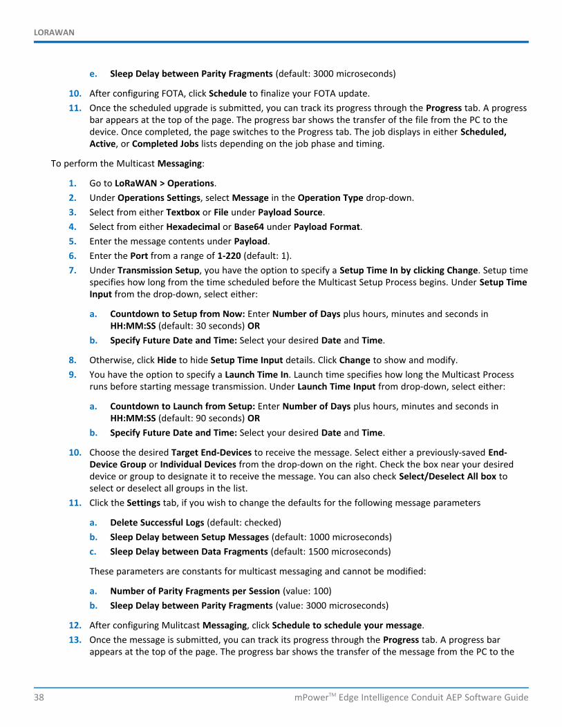
LORAWAN
38 mPowerTM Edge Intelligence Conduit AEP Software Guide
e. Sleep Delay between Parity Fragments (default: 3000 microseconds)
10. After configuring FOTA, click Schedule to finalize your FOTA update.11. Once the scheduled upgrade is submitted, you can track its progress through the Progress tab. A progress
bar appears at the top of the page. The progress bar shows the transfer of the file from the PC to thedevice. Once completed, the page switches to the Progress tab. The job displays in either Scheduled,Active, or Completed Jobs lists depending on the job phase and timing.
To perform the Multicast Messaging:
1. Go to LoRaWAN > Operations.2. Under Operations Settings, select Message in the Operation Type drop-down.3. Select from either Textbox or File under Payload Source.4. Select from either Hexadecimal or Base64 under Payload Format.5. Enter the message contents under Payload.6. Enter the Port from a range of 1-220 (default: 1).7. Under Transmission Setup, you have the option to specify a Setup Time In by clicking Change. Setup time
specifies how long from the time scheduled before the Multicast Setup Process begins. Under Setup TimeInput from the drop-down, select either:
a. Countdown to Setup from Now: Enter Number of Days plus hours, minutes and seconds inHH:MM:SS (default: 30 seconds) OR
b. Specify Future Date and Time: Select your desired Date and Time.
8. Otherwise, click Hide to hide Setup Time Input details. Click Change to show and modify.9. You have the option to specify a Launch Time In. Launch time specifies how long the Multicast Process
runs before starting message transmission. Under Launch Time Input from drop-down, select either:
a. Countdown to Launch from Setup: Enter Number of Days plus hours, minutes and seconds inHH:MM:SS (default: 90 seconds) OR
b. Specify Future Date and Time: Select your desired Date and Time.
10. Choose the desired Target End-Devices to receive the message. Select either a previously-saved End-Device Group or Individual Devices from the drop-down on the right. Check the box near your desireddevice or group to designate it to receive the message. You can also check Select/Deselect All box toselect or deselect all groups in the list.
11. Click the Settings tab, if you wish to change the defaults for the following message parameters
a. Delete Successful Logs (default: checked)b. Sleep Delay between Setup Messages (default: 1000 microseconds)c. Sleep Delay between Data Fragments (default: 1500 microseconds)
These parameters are constants for multicast messaging and cannot be modified:
a. Number of Parity Fragments per Session (value: 100)b. Sleep Delay between Parity Fragments (value: 3000 microseconds)
12. After configuring Mulitcast Messaging, click Schedule to schedule your message.13. Once the message is submitted, you can track its progress through the Progress tab. A progress bar
appears at the top of the page. The progress bar shows the transfer of the message from the PC to the

LORAWAN
mPowerTM Edge Intelligence Conduit AEP Software Guide 39
device. Once completed, the page switches to the Progress tab. The job displays in either Scheduled,Active, or Completed Jobs lists depending on the job phase and timing.
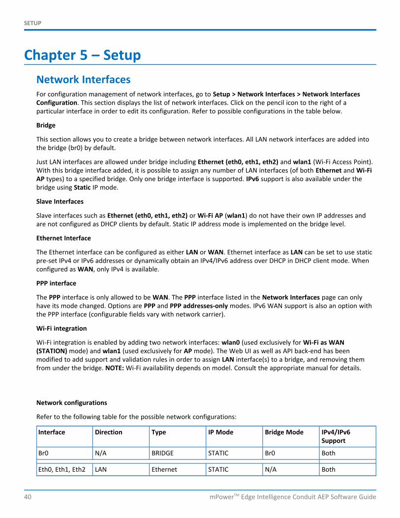
SETUP
40 mPowerTM Edge Intelligence Conduit AEP Software Guide
Chapter 5 – SetupNetwork InterfacesFor configuration management of network interfaces, go to Setup > Network Interfaces > Network InterfacesConfiguration. This section displays the list of network interfaces. Click on the pencil icon to the right of aparticular interface in order to edit its configuration. Refer to possible configurations in the table below.
Bridge
This section allows you to create a bridge between network interfaces. All LAN network interfaces are added intothe bridge (br0) by default.
Just LAN interfaces are allowed under bridge including Ethernet (eth0, eth1, eth2) and wlan1 (Wi-Fi Access Point).With this bridge interface added, it is possible to assign any number of LAN interfaces (of both Ethernet and Wi-FiAP types) to a specified bridge. Only one bridge interface is supported. IPv6 support is also available under thebridge using Static IP mode.
Slave Interfaces
Slave interfaces such as Ethernet (eth0, eth1, eth2) or Wi-Fi AP (wlan1) do not have their own IP addresses andare not configured as DHCP clients by default. Static IP address mode is implemented on the bridge level.
Ethernet Interface
The Ethernet interface can be configured as either LAN or WAN. Ethernet interface as LAN can be set to use staticpre-set IPv4 or IPv6 addresses or dynamically obtain an IPv4/IPv6 address over DHCP in DHCP client mode. Whenconfigured as WAN, only IPv4 is available.
PPP interface
The PPP interface is only allowed to be WAN. The PPP interface listed in the Network Interfaces page can onlyhave its mode changed. Options are PPP and PPP addresses-only modes. IPv6 WAN support is also an option withthe PPP interface (configurable fields vary with network carrier).
Wi-Fi integration
Wi-Fi integration is enabled by adding two network interfaces: wlan0 (used exclusively for Wi-Fi as WAN(STATION) mode) and wlan1 (used exclusively for AP mode). The Web UI as well as API back-end has beenmodified to add support and validation rules in order to assign LAN interface(s) to a bridge, and removing themfrom under the bridge. NOTE: Wi-Fi availability depends on model. Consult the appropriate manual for details.
Network configurations
Refer to the following table for the possible network configurations:
Interface Direction Type IP Mode Bridge Mode IPv4/IPv6Support
Br0 N/A BRIDGE STATIC Br0 Both
Eth0, Eth1, Eth2 LAN Ethernet STATIC N/A Both
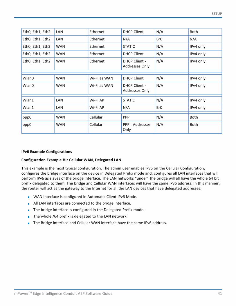
SETUP
mPowerTM Edge Intelligence Conduit AEP Software Guide 41
Eth0, Eth1, Eth2 LAN Ethernet DHCP Client N/A Both
Eth0, Eth1, Eth2 LAN Ethernet N/A Br0 N/A
Eth0, Eth1, Eth2 WAN Ethernet STATIC N/A IPv4 only
Eth0, Eth1, Eth2 WAN Ethernet DHCP Client N/A IPv4 only
Eth0, Eth1, Eth2 WAN Ethernet DHCP Client -Addresses Only
N/A IPv4 only
Wlan0 WAN Wi-Fi as WAN DHCP Client N/A IPv4 only
Wlan0 WAN Wi-Fi as WAN DHCP Client -Addresses Only
N/A IPv4 only
Wlan1 LAN Wi-Fi AP STATIC N/A IPv4 only
Wlan1 LAN Wi-Fi AP N/A Br0 IPv4 only
ppp0 WAN Cellular PPP N/A Both
ppp0 WAN Cellular PPP - AddressesOnly
N/A Both
IPv6 Example Configurations
Configuration Example #1: Cellular WAN, Delegated LAN
This example is the most typical configuration. The admin user enables IPv6 on the Cellular Configuration,configures the bridge interface on the device in Delegated Prefix mode and, configures all LAN interfaces that willperform IPv6 as slaves of the bridge interface. The LAN networks “under” the bridge will all have the whole 64 bitprefix delegated to them. The bridge and Cellular WAN interfaces will have the same IPv6 address. In this manner,the router will act as the gateway to the Internet for all the LAN devices that have delegated addresses.
WAN interface is configured in Automatic Client IPv6 Mode.All LAN interfaces are connected to the bridge interface.The bridge interface is configured in the Delegated Prefix mode.The whole /64 prefix is delegated to the LAN network.The Bridge interface and Cellular WAN interface have the same IPv6 address.
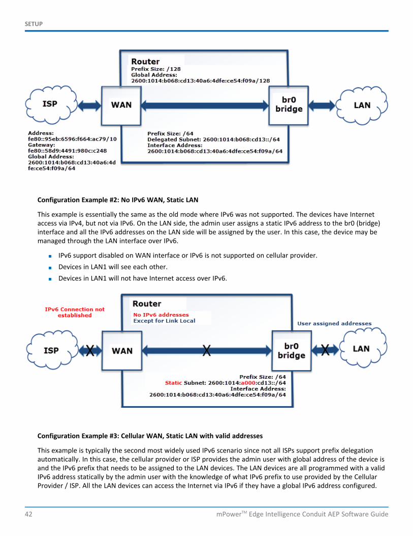
SETUP
42 mPowerTM Edge Intelligence Conduit AEP Software Guide
Configuration Example #2: No IPv6 WAN, Static LAN
This example is essentially the same as the old mode where IPv6 was not supported. The devices have Internetaccess via IPv4, but not via IPv6. On the LAN side, the admin user assigns a static IPv6 address to the br0 (bridge)interface and all the IPv6 addresses on the LAN side will be assigned by the user. In this case, the device may bemanaged through the LAN interface over IPv6.
IPv6 support disabled on WAN interface or IPv6 is not supported on cellular provider.Devices in LAN1 will see each other.Devices in LAN1 will not have Internet access over IPv6.
Configuration Example #3: Cellular WAN, Static LAN with valid addresses
This example is typically the second most widely used IPv6 scenario since not all ISPs support prefix delegationautomatically. In this case, the cellular provider or ISP provides the admin user with global address of the device isand the IPv6 prefix that needs to be assigned to the LAN devices. The LAN devices are all programmed with a validIPv6 address statically by the admin user with the knowledge of what IPv6 prefix to use provided by the CellularProvider / ISP. All the LAN devices can access the Internet via IPv6 if they have a global IPv6 address configured.
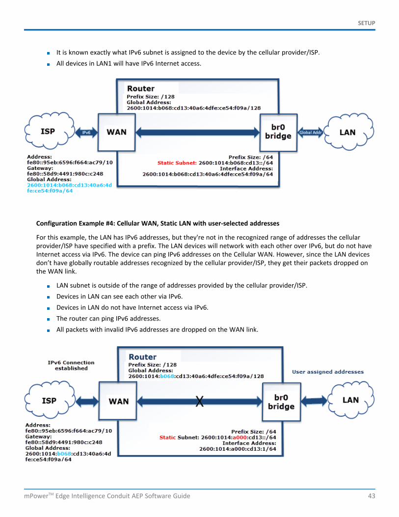
SETUP
mPowerTM Edge Intelligence Conduit AEP Software Guide 43
It is known exactly what IPv6 subnet is assigned to the device by the cellular provider/ISP.All devices in LAN1 will have IPv6 Internet access.
Configuration Example #4: Cellular WAN, Static LAN with user-selected addresses
For this example, the LAN has IPv6 addresses, but they're not in the recognized range of addresses the cellularprovider/ISP have specified with a prefix. The LAN devices will network with each other over IPv6, but do not haveInternet access via IPv6. The device can ping IPv6 addresses on the Cellular WAN. However, since the LAN devicesdon’t have globally routable addresses recognized by the cellular provider/ISP, they get their packets dropped onthe WAN link.
LAN subnet is outside of the range of addresses provided by the cellular provider/ISP.Devices in LAN can see each other via IPv6.Devices in LAN do not have Internet access via IPv6.The router can ping IPv6 addresses.All packets with invalid IPv6 addresses are dropped on the WAN link.
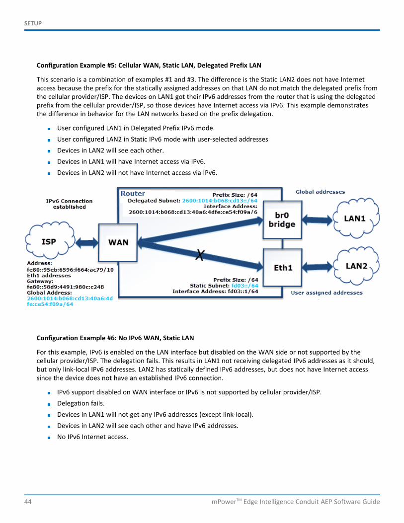
SETUP
44 mPowerTM Edge Intelligence Conduit AEP Software Guide
Configuration Example #5: Cellular WAN, Static LAN, Delegated Prefix LAN
This scenario is a combination of examples #1 and #3. The difference is the Static LAN2 does not have Internetaccess because the prefix for the statically assigned addresses on that LAN do not match the delegated prefix fromthe cellular provider/ISP. The devices on LAN1 got their IPv6 addresses from the router that is using the delegatedprefix from the cellular provider/ISP, so those devices have Internet access via IPv6. This example demonstratesthe difference in behavior for the LAN networks based on the prefix delegation.
User configured LAN1 in Delegated Prefix IPv6 mode.User configured LAN2 in Static IPv6 mode with user-selected addressesDevices in LAN2 will see each other.Devices in LAN1 will have Internet access via IPv6.Devices in LAN2 will not have Internet access via IPv6.
Configuration Example #6: No IPv6 WAN, Static LAN
For this example, IPv6 is enabled on the LAN interface but disabled on the WAN side or not supported by thecellular provider/ISP. The delegation fails. This results in LAN1 not receiving delegated IPv6 addresses as it should,but only link-local IPv6 addresses. LAN2 has statically defined IPv6 addresses, but does not have Internet accesssince the device does not have an established IPv6 connection.
IPv6 support disabled on WAN interface or IPv6 is not supported by cellular provider/ISP.Delegation fails.Devices in LAN1 will not get any IPv6 addresses (except link-local).Devices in LAN2 will see each other and have IPv6 addresses.No IPv6 Internet access.
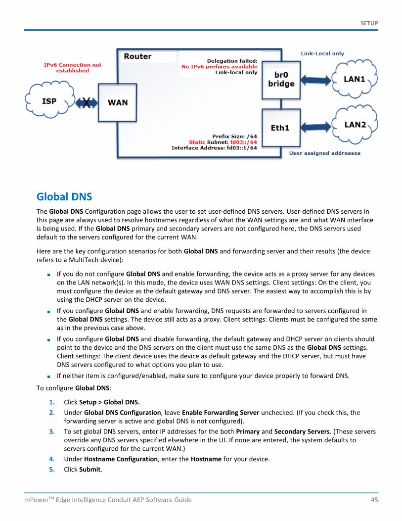
SETUP
mPowerTM Edge Intelligence Conduit AEP Software Guide 45
Global DNSThe Global DNS Configuration page allows the user to set user-defined DNS servers. User-defined DNS servers inthis page are always used to resolve hostnames regardless of what the WAN settings are and what WAN interfaceis being used. If the Global DNS primary and secondary servers are not configured here, the DNS servers useddefault to the servers configured for the current WAN.
Here are the key configuration scenarios for both Global DNS and forwarding server and their results (the devicerefers to a MultiTech device):
If you do not configure Global DNS and enable forwarding, the device acts as a proxy server for any deviceson the LAN network(s). In this mode, the device uses WAN DNS settings. Client settings: On the client, youmust configure the device as the default gateway and DNS server. The easiest way to accomplish this is byusing the DHCP server on the device.If you configure Global DNS and enable forwarding, DNS requests are forwarded to servers configured inthe Global DNS settings. The device still acts as a proxy. Client settings: Clients must be configured the sameas in the previous case above.If you configure Global DNS and disable forwarding, the default gateway and DHCP server on clients shouldpoint to the device and the DNS servers on the client must use the same DNS as the Global DNS settings.Client settings: The client device uses the device as default gateway and the DHCP server, but must haveDNS servers configured to what options you plan to use.If neither item is configured/enabled, make sure to configure your device properly to forward DNS.
To configure Global DNS:
1. Click Setup > Global DNS.2. Under Global DNS Configuration, leave Enable Forwarding Server unchecked. (If you check this, the
forwarding server is active and global DNS is not configured).3. To set global DNS servers, enter IP addresses for the both Primary and Secondary Servers. (These servers
override any DNS servers specified elsewhere in the UI. If none are entered, the system defaults toservers configured for the current WAN.)
4. Under Hostname Configuration, enter the Hostname for your device.5. Click Submit.
SETUP
46 mPowerTM Edge Intelligence Conduit AEP Software Guide
6. Click Save and Restart to save your changes.
WAN SetupConfiguring WAN Failover Priority
Failover mode regulates which WAN is used for the Internet connection and switches the WAN if a connectivityfailure is detected.
Failover mode enables the WAN with the highest priority as displayed on the WAN Configuration page. If the WANwith priority 1 is disabled or a connection failure is detected, the WAN with priority 2 is automatically selected forestablishing connection to the Internet.
Ethernet (eth0) is priority 1 by default.
If Ethernet is used as WAN, the DHCP server must be disabled.
1. Click Setup > WAN Configuration.2. Under Options, click the up and down arrows to change the priority of the appropriate WAN.3. Click Save and Restart to save the change.
For field descriptions see Failover Configuration Fields
For information on editing WAN Failover see Editing Failover Configuration
Editing Failover ConfigurationThe device can use the active or passive mode to monitor the Internet availability in WAN. The default condition isactive mode.
Active mode can be type ICMP (ping) or TCP. ICMP periodically pings the designated host at the specified interval.TCP tries to make a connection to the designated host at the interval specified.
For both ICMP and TCP, if a response is not received, the device switches to the WAN with lower priority. Thedevice continues to ping the designated host at the interval specified for WAN with the higher priority andswitches back when the ping is successful. When passive mode is enabled, the device switches the WANs when thenetwork interface is down. The currently active WAN is displayed on the home page under the label WANTransport.
To edit failover configuration:
1. Click Setup > WAN Configuration.2. Under the Options column at the right, click the pencil icon (edit) for the selected WAN. The Failover
Configuration page is displayed.3. Make the desired changes. Refer to Failover Configuration Fields for details.4. Click Finish.5. If you are finished making changes, click Save and Restart.
Failover Configuration FieldsField Description
Monitoring Mode Use the drop-down list to select the mode to connect to the host: PASSIVE orACTIVE.
SETUP
mPowerTM Edge Intelligence Conduit AEP Software Guide 47
Field Description
Interval Enter the number of seconds between each check. Default is 60 seconds.
Host Name Enter the host name or IP address to use for the check. Default is www.google.com.
Mode Type Use the drop-down list to select the mode type: ICMP or TCP. Default is ICMP.(Active Monitoring Mode)
TCP Port Enter the TCP Port number to connect to the host. (Mode TCP)
ICMP Port Enter the number of ICMP pings to be sent to the specified host. Default is 10.(Mode ICMP)
Configuring IP Address for LANYour device manages traffic for your local area network (LAN). To change the IP address and DNS configuration:
1. Go to Setup > Network Interfaces > br0 and click the pencil icon to edit.
2. To configure the address LAN information:In the IP Address field, type the device's IP address. The default is 192.168.2.1.In the Mask field, type the mask for the network. The default is 255.255.255.0.
3. To resolve domain names, configure domain name server information (DNS), go to Setup > Global DNSand refer to the Global DNS section (WAN DNS) for options and instructions on how to properly configurethis feature.
4. Click Submit.5. To save your changes, click Save and Restart.
Configuring Dynamic Domain Naming System (DDNS)This feature allows your router to use a DDNS service to associate a hosted server's domain name with adynamically changing internet address. To configure your router to use DDNS:
1. From Setup, select DDNS Configuration.2. In the Configuration group, check Enabled.3. In the Service drop-down list, select a DDNS service. To define a service that isn't listed choose Custom.
a. For custom DDNS service, in the Service field, type the DDNS server's URL.b. For custom DDNS service, in the Port field, type the DDNS server's port.
4. In the Domain field, type the registered Domain name.5. In the Update Interval field, type the days that can pass with no IP Address change. At the end of this
interval, the existing IP Address is updated on the server so that the address does not expire. The rangeof the interval you can enter is between 1 and 99 days. The default is 28 days.
6. Check Use Check IP, if you want to query the server to determine the IP address before the DDNS update.The IP address is still assigned by the wireless provider and the DDNS is updated based on the addressreturned by Check IP Server. If disabled, the DDNS update uses the IP address from the PPP link. Thedefault is Use Check IP.
7. In the Check IP Server field, type the name to which the IP Address change is registered. Example:checkip.dyndns.org
8. In the Check IP Port field, type the port number of the Check IP Server. The default is 80.
SETUP
48 mPowerTM Edge Intelligence Conduit AEP Software Guide
9. Click Submit.10. To save your changes, click Save and Restart.
Entering authentication informationYour DDNS server requires you to identify yourself before you can make changes.
1. In the Username field, type the name that can access the DDNS Server. The default is NULL. You receiveyour name when you register with the DDNS service.
2. In the Password field, type the password that can access the DDNS Server. The default is NULL. Youreceive your password when you register with the DDNS service.
3. Click Submit. If you are finished making changes click Save and Restart.
Forcing a DDNS server updateTo update the DDNS server with your IP address, click Update.
Configuring Dynamic Host Configuration Protocol (DHCP) ServerTo view, add, or edit DHCP servers, see the IPv4 DHCP Servers (IPv4 support) or DHCPv6 and RouterAdvertisement (for IPv6 support) list under Setup > DHCP Configuration.
You can configure multiple DHCP servers. Only one DHCP server can be created per LAN network interface. You canconfigure your device to function as DHCP server that supply network configuration information, such as IPaddress, subnet mask, and broadcast address, to devices on the network.
By default, the DHCP server is configured and enabled for Bridge (br0) network interface. If a LAN networkinterface is NOT under the bridge, DHCP server can be configured and enabled for it..
DHCP Server is disabled automatically if you modify the network interface under Setup > Network Interfaceincluding:
changes to the interface subnetadding network interface under the bridgechanges the interface from LAN to WAN (Ethernet interface only)removes all LANs from under the bridge (DHCP for br0 will be disabled in this case)
DHCP Server cannot be enabled if the network interface is under the bridge, or is not enabled or configuredproperly (for example, when eth0 is configured as WAN, or Wi-Fi Access Point is disabled).
To edit the configuration of an existing IPv4 DHCP server or add a new one:
1. Go to Setup > DHCP Configuration. See the IPv4 DHCP Servers list.2. To edit a DHCP Server, click the pencil icon (edit) for the selected interface, OR to add a DHCP Server,
click the Add IPv4 DHCP Server button.3. The DHCP Configuration fields appear. To use the DHCP feature, check Enabled.4. In the Interface field, select the network interface. Note: Interface field is read-only when you edit DHCP
Server.5. The Subnet field displays the subnet address.6. The Mask field displays the network's subnet mask.7. In the Gateway field, type the gateway address.
SETUP
mPowerTM Edge Intelligence Conduit AEP Software Guide 49
8. In the Domain field, type your network domain, if any.9. In the Lease Time field, enter the DHCP lease time. Lease time is set in days, hours, and minutes (dd-hh-
mm). A Lease Time of 00-00-00 is an infinite lease time.10. In the Lease Range Start field and in the Lease Range End field, type the range of IP addresses to be
assigned by DHCP.11. Click Submit. If you are finished making changes, click Save and Restart.
To edit the configuration of an existing DHCPv6 and Router Advertisement server or add a new one:
1. Go to Setup > DHCP Configuration. See the DHCPv6 and Router Advertisement list.2. To edit a DHCP Server, click the pencil icon (edit) for the selected interface, OR to add a DHCP Server,
click the Add DHCPv6/RA button.3. The DHCP Configuration fields appear. To use the DHCP feature, check Enabled.4. In the Interface field, select the network interface from the drop-down including eth0 and wlan1. Note:
Interface field is read-only when you edit DHCP Server.5. In the Router Advertisement Mode, select from the drop-down the DHCP IPv6 mode including SLAAC or
Stateless DHCP.6. In the Lease Time field, type the DHCP lease time. Lease time is set in days, hours, and minutes (dd-hh-
mm). A Lease Time of 00-00-00 is an infinite lease time.7. Click Submit. If you are finished making changes, click Save and Restart.
To add fixed addresses for the DCHP server, see Assigning Fixed Addresses.
Assigning Fixed AddressesTo add fixed addresses for the DCHP server make the changes under the Fixed Addresses section on the DCHPConfiguration page:
1. In the MAC Address field, type the MAC address to which the specified IP address binds.2. In the IP Address field, type the fixed IP address to be assigned.3. Click Add.4. To save your changes, click Save and Restart.
Configuring SNMPThe device offers Simple Network Management Protocol (SNMP) which is used for collecting information fromnetwork devices on an IP network.
You also have the option to configure SNMP traps which are alerts sent from SNMP-enabled devices to an SNMPagent or manager typically providing device status or condition information.
You can also access the MIB file which is a management information base. This file is a formal description of a setof network objects managed using the Simple Network Management Protocol (SNMP). The format of the MIB isdefined as part of the SNMP. (All other MIBs are extensions of this basic management information base.)
Click Download MIB, to download the MIB file.
To configure SNMP:
1. Go to Setup > SNMP Configuration.2. Under SNMP Server Configuration, check Enabled to activate the SNMP server. Click Submit.
SETUP
50 mPowerTM Edge Intelligence Conduit AEP Software Guide
3. If needed, click Add under Allowed IP Addresses for SNMP v1/v2c.4. Click Add Server Configuration.
a. Make sure that Enabled is checked.b. Under Version, select from the drop-down either SNMP v1/v2c or SNMP v3.c. For SNMP v1 and SNMP v2c:
i. Enter the Configuration Name for your SNMP configuration.ii. Enter Community String which is a read-only string used to authenticate incoming SNMP
requests.
d. For SNMP v3:
i. Enter the Authentication Protocol from the drop-down, including NONE, MD5, or SHA1.ii. Enter the Security Name which is a username used to authenticate incoming SNMP v3
requests. If you selected MD5 or SHA1 for Authentication Protocol:Enter the Authentication Password, which is a password used to authenticateincoming SNMPv3 requests.Confirm the password.
iii. Enter the Encryption Protocol for SNMPv3 messages from the drop-down, including NONE, DESor AES-128. If you selected DES or AES-128 for Encryption Protocol:
Enter the Encryption Password.Confirm the password.
e. Click Submit.
5. The SNMP Configuration list displays your recently added SNMP Server Configuration. To edit theconfiguration, click the pencil icon under Options.
6. To delete an existing configuration, click the trash can icon under Options.7. To save your changes, click Save and Restart. Or continue to SNMP Trap Destinations and Add Trap
Destinations.
To configure SNMP Traps:
1. Go to Setup > SNMP Configuration > SNMP Trap Configuration, check Enabled to enable sending SNMPtraps on the device..
2. The engine ID displays to the right of Enabled. Modify the engine ID or use the default value.3. Click Submit.4. Click Add Trap Destination.
a. Make sure that Enabled box is checked.b. Enter the Destination Name.c. Select from the drop-down the Version of SNMP (SNMP v1/v2c or SNMP v3).d. For SNMP v1 or SNMP v2c
i. Enter the Destination IP Address.ii. Enter the Community String.
e. For SNMPv3:
SETUP
mPowerTM Edge Intelligence Conduit AEP Software Guide 51
i. Enter the Destination IP Address.ii. Enter Security Name.iii. Enter the Authentication Protocol from the drop-down, including NONE, MD5, or SHA1. If you
selected MD5 or SHA1 for Authentication Protocol:
i. Enter the Authentication Password, which is a password used to authenticate incomingSNMPv3 requests.
ii. Confirm the password.
iii. Enter the Encryption Protocol for SNMPv3 messages from the drop-down, including NONE,DES, or AES-128. If you selected DES or AES-128 for Encryption Protocol:
i. Enter the Encryption Password.ii. Confirm the password.
f. Click Submit.
5. The SNMP Trap Destination list displays your recently added SNMP Trap Destination. To edit thedestination, click the pencil icon under Options.
6. To delete an existing destination, click the trash can icon under Options.7. To save your changes, click Save and Restart.
To download the MIB file:
1. Click Download MIB in the far right corner of the device display.2. Download/save the file from your browser.
Configuring the Global Positioning System (GPS)This GPS information applies only to the device models that support GPS.
Some devices have a built-in GPS receiver. If your device has a GPS receiver, the device can forward NMEA(National Marine Electronics Association) sentences from the GPS receiver to another device connected to thedevice. You can also send the GPS data over the network to a remote computer.
The key areas of GPS configuration include: Server Configuration, Client Configuration and NMEA Configurationalong with Current Position information.
Notes:
All enabled sentences are forwarded periodically using the interval specified in the NMEA Configurationsection. Before forwarding, the device adds an ID prefix and ID to each enabled NMEA sentence. If set, theNMEA sentences available are those provided by the built-in receiver which are: GPGGA, GPGSA, GPGSV,GPGLL, GPRMC, GPVTG.You can simultaneously enable the TCP Server, and TCP/UDP client.
GPS Server ConfigurationTo setup the GPS Server Configuration:
1. Go to Setup > GPS Configuration > Server Configuration.2. To enable server configuration, check TCP Server.
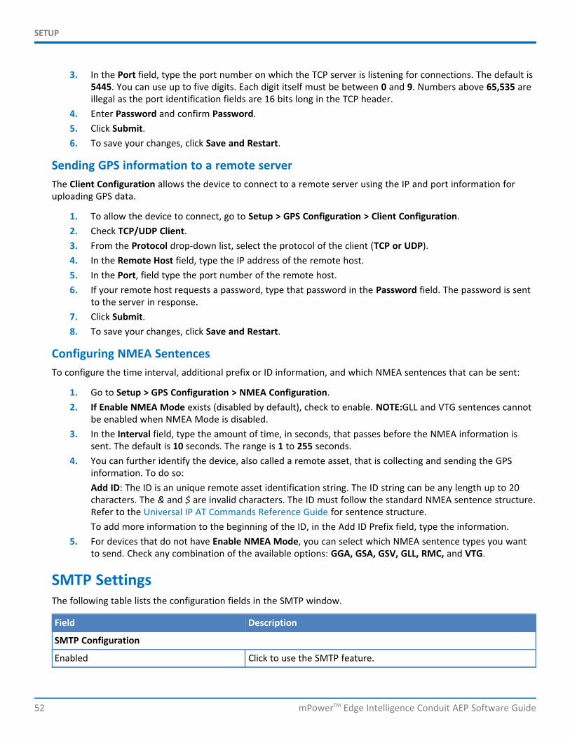
SETUP
52 mPowerTM Edge Intelligence Conduit AEP Software Guide
3. In the Port field, type the port number on which the TCP server is listening for connections. The default is5445. You can use up to five digits. Each digit itself must be between 0 and 9. Numbers above 65,535 areillegal as the port identification fields are 16 bits long in the TCP header.
4. Enter Password and confirm Password.5. Click Submit.6. To save your changes, click Save and Restart.
Sending GPS information to a remote serverThe Client Configuration allows the device to connect to a remote server using the IP and port information foruploading GPS data.
1. To allow the device to connect, go to Setup > GPS Configuration > Client Configuration.2. Check TCP/UDP Client.3. From the Protocol drop-down list, select the protocol of the client (TCP or UDP).4. In the Remote Host field, type the IP address of the remote host.5. In the Port, field type the port number of the remote host.6. If your remote host requests a password, type that password in the Password field. The password is sent
to the server in response.7. Click Submit.8. To save your changes, click Save and Restart.
Configuring NMEA SentencesTo configure the time interval, additional prefix or ID information, and which NMEA sentences that can be sent:
1. Go to Setup > GPS Configuration > NMEA Configuration.2. If Enable NMEA Mode exists (disabled by default), check to enable. NOTE:GLL and VTG sentences cannot
be enabled when NMEA Mode is disabled.3. In the Interval field, type the amount of time, in seconds, that passes before the NMEA information is
sent. The default is 10 seconds. The range is 1 to 255 seconds.4. You can further identify the device, also called a remote asset, that is collecting and sending the GPS
information. To do so:Add ID: The ID is an unique remote asset identification string. The ID string can be any length up to 20characters. The & and $ are invalid characters. The ID must follow the standard NMEA sentence structure.Refer to the Universal IP AT Commands Reference Guide for sentence structure.To add more information to the beginning of the ID, in the Add ID Prefix field, type the information.
5. For devices that do not have Enable NMEA Mode, you can select which NMEA sentence types you wantto send. Check any combination of the available options: GGA, GSA, GSV, GLL, RMC, and VTG.
SMTP SettingsThe following table lists the configuration fields in the SMTP window.
Field Description
SMTP Configuration
Enabled Click to use the SMTP feature.
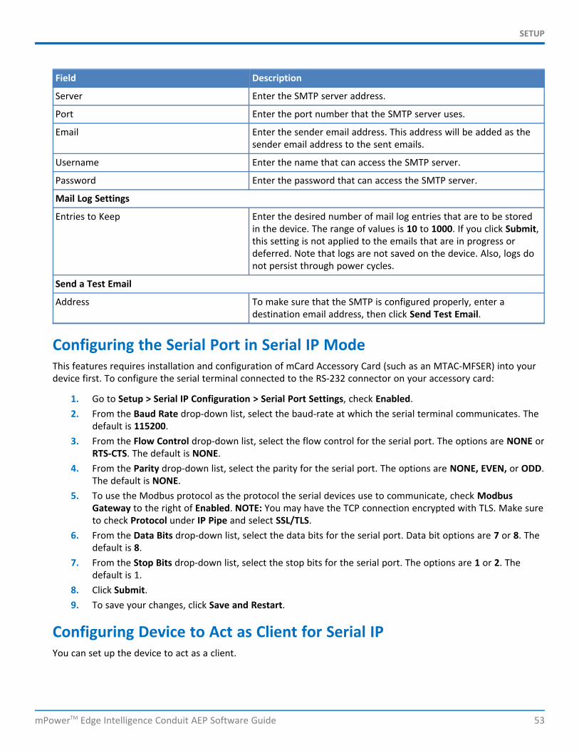
SETUP
mPowerTM Edge Intelligence Conduit AEP Software Guide 53
Field Description
Server Enter the SMTP server address.
Port Enter the port number that the SMTP server uses.
Email Enter the sender email address. This address will be added as thesender email address to the sent emails.
Username Enter the name that can access the SMTP server.
Password Enter the password that can access the SMTP server.
Mail Log Settings
Entries to Keep Enter the desired number of mail log entries that are to be storedin the device. The range of values is 10 to 1000. If you click Submit,this setting is not applied to the emails that are in progress ordeferred. Note that logs are not saved on the device. Also, logs donot persist through power cycles.
Send a Test Email
Address To make sure that the SMTP is configured properly, enter adestination email address, then click Send Test Email.
Configuring the Serial Port in Serial IP ModeThis features requires installation and configuration of mCard Accessory Card (such as an MTAC-MFSER) into yourdevice first. To configure the serial terminal connected to the RS-232 connector on your accessory card:
1. Go to Setup > Serial IP Configuration > Serial Port Settings, check Enabled.2. From the Baud Rate drop-down list, select the baud-rate at which the serial terminal communicates. The
default is 115200.3. From the Flow Control drop-down list, select the flow control for the serial port. The options are NONE or
RTS-CTS. The default is NONE.4. From the Parity drop-down list, select the parity for the serial port. The options are NONE, EVEN, or ODD.
The default is NONE.5. To use the Modbus protocol as the protocol the serial devices use to communicate, check Modbus
Gateway to the right of Enabled. NOTE: You may have the TCP connection encrypted with TLS. Make sureto check Protocol under IP Pipe and select SSL/TLS.
6. From the Data Bits drop-down list, select the data bits for the serial port. Data bit options are 7 or 8. Thedefault is 8.
7. From the Stop Bits drop-down list, select the stop bits for the serial port. The options are 1 or 2. Thedefault is 1.
8. Click Submit.9. To save your changes, click Save and Restart.
Configuring Device to Act as Client for Serial IPYou can set up the device to act as a client.
SETUP
54 mPowerTM Edge Intelligence Conduit AEP Software Guide
The TCP, UDP, SSL/TLS client feature enables the device to act as a proxy TCP, UDP, or SSL/TLS client to the serialterminal connected to the RS-232 port on the device. This helps the serial terminal access any TCP, UDP, or SSL/TLSserver on the LAN/WAN allowing two-way traffic between the serial device and the remote server.
To use this function, you must first check Enabled under Serial Port Settings. To configure the IP Pipe in TCP, UDP,or SSL/TLS client mode:
1. Go to Setup > Serial-IP Configuration > Serial Port Settings > IP Pipe group.2. From the Mode drop-down list, select CLIENT.3. From the Protocol drop-down list, select the desired protocol: TCP, UDP, or SSL/TLS.4. In the Server IP Address field, enter the address of the far-end TCP, UDP, or SSL/TLS server.5. In the Server Port field, enter the port value used by the far-end TCP, UDP, or SSL/TLS server.6. If the primary server is unavailable, in the Secondary IP Address field, enter the address of the alternate
TCP, UDP, or SSL/TLS server.7. If the primary server is unavailable, in the Secondary Port field, enter port number value of the alternate
TCP, UDP, or SSL/TLS server.8. From the Connection Activation drop-down list, select a connection method. Options are:
ALWAYS-ON.CR. Three carriage returns must be received before the TCP, UDP, or SSL/TLS connection is established tothe remote server.ON-DEMAND. Set the connection as available on-demand.
9. From the Connection Termination drop-down list, select a disconnect method for the IP pipe. Optionsare:ALWAYS-ON.TIMEOUT. The IP pipe connection disconnects if the configured timer expires with no data sent orreceived. In the Timeout field, enter the desired number of seconds for this timeout. The valid timeoutrange is from 0 to 900 seconds. Timeout of zero seconds disables the timeout and it is equivalent toALWAYS-ON.SEQUENCE. A sequence of received characters disconnects the IP pipe.
10. In the Buffer Timeout field, enter the timeout after which data is sent to the network if the buffer is notfull (in milliseconds).
11. In the Buffer Size field, enter the size of the buffer for reading data from the serial port and sending tothe network (in bytes). Data is sent when the buffer is full.
12. Click Submit.13. To save your changes, click Save and Restart.
To configure security settings:
1. Make sure you select SSL/TLS under Protocol.2. Under Security Settings, click the Show to the right.3. By default, the Use default cipher suite is checked. If you accept this default, no other action is needed.4. Uncheck this box, if you want to select specific TLS versions and Cipher Suites. These fields appear.5. Select the TLS version. Check either TLSv1.2 or TLSv1.1.
SETUP
mPowerTM Edge Intelligence Conduit AEP Software Guide 55
6. Check your preferred Cipher Suite from the following list: ECDHE-RSA-AES256-GCM-SHA384, ECDHE-RSA-AES256-SHA, DHE-RSA-AES256-GCM-SHA384, AES256-SHA, ECDHE-RSA-AES128-GCM-SHA256, ECDHE-RSA-AES128-SHA, DHE-RSA-AES128-GCM-SHA256, DHE-RSA-AES128-SHA, and/or AES128-SHA
7. Click Submit.8. To save your settings, click Save and Restart.
Configuring Device to Act as Server for Serial IPYou can set up the device to act as a server.
The TCP, UDP, SSL/TLS server feature enables a TCP, UDP, SSL/TLS client on the Ethernet network to connect to theremote serial terminal that is connected to the RS-232 port on the device. The device acts as a TCP, UDP, SSL/TLSserver which allows two-way traffic between the TCP, UDP, SSL/TLS client and the remote terminal on the serialport.
To use this function, you must first check Enabled under Serial Port Settings. To configure the IP Pipe in TCP, UDP,SSL/TLS server mode:
1. Go to Setup > Serial-IP Configuration > Serial Port Settings > IP Pipe group.2. In the Mode drop-down list, select SERVER.3. From the Protocol drop-down list, select the desired protocol: TCP, UDP, or SSL/TLS.4. In the Buffer Timeout field, enter the timeout after which data is sent to the network if the buffer is not
full (in milliseconds).5. In the Server Port field, type the desired port value in the range 1 to 65535.6. In the Buffer Size field, enter the size of the buffer for reading data from the serial port and sending to
the network (in bytes). Data is sent when the buffer is full.7. From the Connection Termination drop-down list, select a disconnect method for the IP pipe. Options
are:ALWAYS-ON.TIMEOUT. The IP pipe connection disconnects if the configured timer expires with no data sent orreceived. In the Timeout field, enter the desired number of seconds for this timeout. The valid timeoutrange is from 0 to 900 seconds. Timeout of zero seconds disables the timeout and it is equivalent toALWAYS-ON.SEQUENCE. A sequence of received characters disconnects the IP pipe.
8. Click Submit.9. To save your changes, click Save and Restart.
To configure security settings:
1. Make sure you select SSL/TLS under Protocol.2. Under Security Settings, click the Show to the right.3. By default, the Use default cipher suite is checked. If you accept this default, no other action is needed.4. Uncheck this box, if you want to select specific TLS versions and Cipher Suites. These fields appear.5. Select the TLS version. Check either TLSv1.2 or TLSv1.1.
SETUP
56 mPowerTM Edge Intelligence Conduit AEP Software Guide
6. Check your preferred Cipher Suite from the following list: ECDHE-RSA-AES256-GCM-SHA384, ECDHE-RSA-AES256-SHA, DHE-RSA-AES256-GCM-SHA384, AES256-SHA, ECDHE-RSA-AES128-GCM-SHA256, ECDHE-RSA-AES128-SHA, DHE-RSA-AES128-GCM-SHA256, DHE-RSA-AES128-SHA, and/or AES128-SHA
7. Click Submit.8. To save your settings, click Save and Restart.
Time ConfigurationYou can configure how your device manages the setting of time on its domain of systems. The system date andtime display in these formats: MM/DD/YYYY HH:MM. You can set the date and time manually, or you canconfigure the device to get this information from an SNTP server.
Setting the Date and TimeTo set the device's date and time:
1. From Setup, select Time Configuration.2. In the Date field, select today's date from the pop-up calendar that opens.3. In the Time field, type the time (24-hour).4. From the Time Zone drop-down list, select your time zone. The default selection is UTC (Universal
Coordinated Time, Universal Time).
Note: To learn more about time zones, visit the following website :http://wwp.greenwichmeantime.com/info/current-time.htm
5. Click Submit.6. To save your changes, click Save and Restart.
Configuring SNTP Client to Update Date and TimeTo configure the server from which the SNTP date and time information is taken, and how often:
1. To enable SNTP to update the date and time, check Enabled.2. In the Polling Time field, type the time that passes (in minutes), after which the SNTP client requests the
server to update the time. Default is 120 minutes.3. In the Server field, type the SNTP server name or IP address that is contacted to update the time.4. In the Backup Server 1 -4 fields, you may enter the SNTP server name or IP address of up to four backup
SNTP servers. These fields are optional.5. Click Submit.6. To save your changes, click Save and Restart.
WIRELESS
mPowerTM Edge Intelligence Conduit AEP Software Guide 57
Chapter 6 – WirelessSetting Up Wi-Fi Access PointIf you ordered a device with Wi-Fi capability, it can be configured as a wireless access point (AP). This allows Wi-Fienabled devices to connect to your device using Wi-Fi. The Wi-Fi access point can have up to 5 clients at a time. Toset up your device as an access point:
1. Go to Wireless > Wi-Fi Access Point.2. To enable Wi-Fi Access Point mode, check Enabled.3. To set the SSID (service set identifier) for the access point supported by your device, in the SSID field,
type the name. The Wi-Fi devices look for this ID in order to join the wireless network. All wirelessdevices on a WLAN must use the same SSID in order to communicate with the access point.
4. To specify the data rates supported, in the Network Mode drop-down list, select the desired option.Possible values are B/G/N-Mixed, B/G-Mixed, B-Only, and N-Only.
5. From the Channel drop-down list, select the channel on which the device operates. Channels 1-11 areavailable.
6. In the Beacon Interval field, enter the period of time, in milliseconds, when the access point sends abeacon packet. Beacons help synchronize a wireless network. For most applications, the default value of100 provides good performance.
7. In the DTIM Interval field, enter how often a beacon frame includes a Delivery Traffic Indication Message,and this number is included in each beacon frame. It is generated within the periodic beacon at afrequency specified by the DTIM Interval. A delivery traffic indication message is a kind of trafficindication message (TIM) which informs the clients about the presence of buffered multicast/broadcastdata on the access point. The default value of 1 provides good performance for most applications. Youmight want to increase this value when using battery powered Wi-Fi devices, which can sleep (at reducedpower consumption) during the longer DTIM interval period. You must balance the power savings fromincreasing the DTIM interval against possible reduced communication throughput.
8. In the RTS Threshold field, type the frame size at which the AP transmissions must use the RTS/CTSprotocol. This is often used to solve hidden node problems. Using a small value causes RTS packets to besent more often, consuming more of the available bandwidth. However, the more RTS packets that aresent, the quicker the system can recover from interference or collisions.
For related information, see Setting Security Options and Viewing Information About Wi-Fi Clients Using Your WirelessNetwork.
Setting Security OptionsSpecify the security protocol that your device uses to secure the communications from it to the connected devicesunder Security Options.
1. From the Mode drop-down list, select the security protocol you want to use. Options include:NoneWEP: Use Wired Equivalent Privacy protocol to allow a group of devices on the network to exchangecoded messages.WPA-PSK: Use Wi-Fi protected access to secure data exchanged on your network.WPA2-PSK: Use Wi-Fi protected access version 2 to secure data exchanged on your network.WPA/WPA2-PSK: Use Wi-Fi protected access version 1 and 2 to secure data exchanged on your network.
WIRELESS
58 mPowerTM Edge Intelligence Conduit AEP Software Guide
2. To select WEP mode:
a. From the Encryption drop-down list, select the encryption to be used. Choose from 64 bit 10 hexdigits or 128 bit 26 hex digits.
b. To generate a key from a phrase, in the Passphrase field, type a phrase. Click Generate.c. To manually enter keys, type the keys in the Key 1, Key 2, Key 3 or Key 4 fields.
3. To select WPA-PSK, WPA2-PSK or WPA-PSK/WPA2-PSK modes:
a. Select the WPA Algorithm from the drop-down list. Choose from TKIP, AES or TKIP+AES.b. In the Shared Key field, type the key that is used for encrypting and decrypting the data.c. To remove the mask characters, thereby making the Shared Key visible, check Unmask.
4. When done, click Submit.5. To save your changes, click Save and Restart.
Viewing Information About Wi-Fi Clients Using Your Wireless NetworkTo view information about clients (such as computers, tablets, and smart phones) that are connected to yourdevice's Wi-Fi access point:
1. The Clients group displays a list of clients using your device's Wi-Fi.2. To update the list, click Refresh.
Setting Up Wi-Fi as WANTo setup the device's Wi-Fi as WAN:
1. Go to Wireless > Wi-Fi as WAN.2. To enable Wi-Fi as WAN mode, check Enabled.3. Click Save and Restart. Note: Save and Restart the device to get a list of available Wi-Fi Networks.4. Go to Wireless > Wi-Fi as WAN.5. Searching for available Wi-Fi networks starts automatically. After 30 to 60 seconds, a list of detected Wi-
Fi Access Points appears in the Available Networks group.6. In the Available Wi-Fi Networks group, click the SSID for the Wi-Fi access point you want to use. The Add
Saved Network window opens. Here are the available fields to enter information:Network NameHidden Network(only check if your target network is currently hidden)SSIDSecurity Mode: None, WEP, WPA, WPA-PSK, WPA-2, or WPA-2-PSKUsernamePasswordUnmask (Check, Uncheck)WPA Algorithm: TKIP, +AES, TKIP, or AESShared KeyKey Index: 0 - 3Network KeyIEEE 802.1x
WIRELESS
mPowerTM Edge Intelligence Conduit AEP Software Guide 59
7. Review the information, enter any required security info, then click Finish. The Wi-Fi access point you justadded appears in the Saved Wi-Fi Networks group.
8. If desired, add additional access points to the list of Saved Networks. The device tries to connect to SavedWi-Fi Networks in the order they are listed. You can change the order by clicking the up or down arrowsshown under Options.
9. When finished, click Save and Restart. The Status field displays "Connected" if you have successfullyconnected to the Wi-Fi access point.
Note: You cannot edit the network name and you cannot delete a network if it is used in another configuration.
Setting up BluetoothThe Bluetooth-IP feature allows a data connection between a remote TCP/UDP client or server and a localBluetooth device. To set up the Bluetooth connection:
1. Go to Wireless > Bluetooth-IP2. To enable the feature, check Enabled. Click Submit.3. Confirm that the far-end Bluetooth device is powered on and waiting for a connection.4. In the Available Devices group, click Refresh. A list of detected Bluetooth devices appears.5. Click the name of the Bluetooth device that you want to use. The name and MAC address appear under
the Selected Device.6. To add a device, click Add Device and enter the device name and the MAC address.7. Click Finish.8. To save your changes, click Save and Restart.
Note: You cannot edit the network name and you cannot delete a network if it is used in another configuration.
IP Pipe in TCP/UDP Server mode
1. In the IP Pipe group, from the Mode drop-down list, select SERVER.2. From the Protocol drop-down list, select the desired protocol, either TCP or UDP.3. In the Server Port field, type the desired port value in the range 1 to 65535.4. From the Connection Termination drop-down list, select a disconnect method for the IP pipe. Options
are:
ALWAYS-ONSEQUENCE: A sequence of characters received from the Bluetooth side used to disconnect the IP pipe.TIMEOUT: The IP pipe connection disconnects if the configured timer expires with no data sent orreceived. A timeout of zero seconds disables the timeout, it is equivalent to ALWAYS-ON.
To configure the IP Pipe in TCP/UDP Client mode
1. In the IP Pipe group, from the Mode drop down list, select CLIENT.2. From the Protocol drop-down list, select the desired protocol, either TCP or UDP.3. In the Server IP Address field, type the address of the far-end TCP-UDP server.4. In the Server Port field, type the port value used by the far-end TCP/UDP Server.5. In case the primary server is unavailable, in the Secondary IP Address field and in the Secondary Port
field, type the IP address and port number, respectively, of the alternate TCP/UDP server.6. From the Connection Activation drop-down list, select a connection method. Options are:

WIRELESS
60 mPowerTM Edge Intelligence Conduit AEP Software Guide
ALWAYS-ONON-DEMANDCR: Three carriage returns must be received from the Bluetooth side before TCP/UDPconnection is established to the remote server.
7. From the Connection Termination drop-down list select a disconnect method for the IP pipe. Options are:ALWAYS-ON:TIMEOUT: The IP pipe connection disconnects if the configured timer expires with no datasent or received. A timeout of zero seconds disables the timeout, it is equivalent to ALWAYS-ON.SEQUENCE: A sequence of characters received from the Bluetooth side used to disconnect theIP pipe.
8. Click Submit.9. To save your changes, click Save and Restart.
The device immediately connects to the local Bluetooth device. If successful the Status fielddisplays Connected. If IP Pipe is configured for SERVER, the IP connection is initiated by thefar-end TCP/UDP client.If Mode is set to CLIENT, the device initiates connections for the far-end TCP/UDP serverbased on the configured Connection Activation conditions are met.
To configure security settings:
1. Make sure you select SSL/TLS under Protocol.2. Under Security Settings, click the Show to the right.3. By default, the Use default cipher suite is checked. If you accept this default, no other action is needed.4. Uncheck this box, if you want to select specific TLS versions and Cipher Suites. These fields appear.5. Select the TLS version. Check either TLSv1.2 or TLSv1.1.6. Check your preferred Cipher Suite from the following list: ECDHE-RSA-AES256-GCM-SHA384, ECDHE-RSA-
AES256-SHA, DHE-RSA-AES256-GCM-SHA384, AES256-SHA, ECDHE-RSA-AES128-GCM-SHA256, ECDHE-RSA-AES128-SHA, DHE-RSA-AES128-GCM-SHA256, DHE-RSA-AES128-SHA, and/or AES128-SHA
7. Click Submit.8. To save your settings, click Save and Restart.
Bluetooth Low Energy (BLE)Bluetooth Low Energy allows you to search and/or scan for BLE devices. You can connect with selected BLE deviceto obtain the list of UUIDs for services and characteristics that are supported on the device.
A python library called gattlib is integrated into the device and can be used for scans, reads, writes, and handlingnotifications.
You must develop a custom application to read and accept the data from a BLE device. Please refer to the exampleon the BLE for mLinux page as well as the Creating a Custom Application page.
1. Go to Wireless > Bluetooth Low Energy > Settings, check the Enabled box.2. Under Power Mode, select from the drop-down including Custom, High, Medium or Low.3. Click Submit.4. Under the Available Device Servers, the detected BLE devices appear.

WIRELESS
mPowerTM Edge Intelligence Conduit AEP Software Guide 61
5. To choose a device from the Available Device Servers, click on the name of your desired device.6. If you do not see your desired device, click Add Device. Enter the Name and MAC Address of your BLE
device.7. Click OK. Your device appears under Saved Devices.8. Click Save and Restart to save your changes.
You may also restart BLE by clicking Reset Bluetooth above Saved Devices section.
FIREWALL
62 mPowerTM Edge Intelligence Conduit AEP Software Guide
Chapter 7 – FirewallDefining Firewall RulesThe device's firewall enforces a set of rules that determine how incoming and outgoing packets are handled. Bydefault, all outbound traffic originating from the LAN is allowed to pass through the firewall, and all inbound trafficoriginating from external networks is dropped. This effectively creates a protective barrier between the LAN andall other networks.
The firewall is built on top of iptables. The different rule groups correspond to their respective chains in iptables.
Note: As a best security practice, the device employs minimum firewall rules by default. This means by default thedevice allows all outbound traffic from it in the Output Filter Rules. (Traffic through the device is handled by thePort/Inbound Forwarding Rules.) But all traffic to the device via WAN interfaces is blocked by default in the InputFilter Rules. Users may create their own specific and targeted input filter rules to allow certain traffic to the devicebased on their specific needs. For additional information, see:
Adding Port Forwarding RulesAdding Input Filter RulesAdding Output Filter RulesAdvanced Settings
Trusted IPTrusted IP is a simplified interface to create iptables rules to allow or block specific IPs, IP ranges, or subnets. Thisfeature allows users to create whitelists (which are allowed or trusted IPs) or black lists (which are blocked orunwanted IPs). You can add, edit, and delete IP addresses as needed.
If you select White List as Trusted IP Mode and you do not set any IP range, no traffic will be allowed. If you selectBlack List as Trusted IP Mode and you do not set any IP range, all traffic will be allowed.
To set up a Trusted IP range:
1. Go to Firewall > Trusted IP.2. Check the Enabled box to turn on Trusted IP.3. Select the Trusted IP Mode from the drop-down, either White List or Black List. (NOTE: Be aware of the
behavior of each list and its consequences based on your specific configuration. For example, if you selectWhite List as Trusted IP Mode, you should include the device IP Address Range or IP Address and SubnetMask to maintain your local device LAN access.)
4. To add IP addresses, click Add IP Range in the upper right corner.5. Under the Add IP Range, enter or select the following parameters:
a. Nameb. Mode from drop-down, either Subnet or IP Range.c. For Subnet:
i. IP Addressii. Subnet Mask
d. For IP Range:

FIREWALL
mPowerTM Edge Intelligence Conduit AEP Software Guide 63
i. IP Address Startii. IP Address End
e. Destination Port (default: ANY)f. Protocol from drop-down including ANY, TCP/UDP, TCP, or UDPg. Click Finish.
6. The system displays your recently added and existing IP ranges in a list. The list includes the relevantdetails. You may edit any IP ranges by clicking on the pencil icon under Options.
7. You may delete any IP ranges by clicking on the trash can icon under Options.8. If you want to revert back to default settings (where Trusted IP is disabled and all IP ranges are removed),
click the Reset to Default button in the lower right corner9. Click Submit.10. To save your changes, click Save and Restart.
Prerouting RuleAdd a DNAT rule
To add prerouting or DNAT rule to your firewall:
1. Go to Firewall > Settings to display the Firewall window.2. In the Prerouting Rules group, click Add DNAT Rule.3. In the Filter Rule section, enter a name for the rule and optionally, a description.4. In the Destination IP field, enter the destination IP address that applies to this rule.5. In the Destination Port field, enter the destination port that applies to this rule. If there is a range of
ports, the ending port is automatically set.6. In the Destination Mask field, enter the subnet mask of the destination that applies to this rule.7. In the Destination Interface field, select the interface used by the destination that applies to this rule
from the drop-down menu. Select from ANY, LAN, WAN, ETHERNET, CELLULAR, WI-FI WAN, WI-FI AP, orOPENVPN.
8. In the Source IP field, enter the source IP address that applies to this rule.9. In the Source Port field, enter the source port that applies to this rule.10. In the SourceMask field, enter source subnet mask that applies to this rule.11. In the SourceMAC field, enter the source MAC address for the device that applies to this rule.12. In the SourceInterface field, select the source interface that applies to this rule from the drop-down
menu. Select from ANY, LAN, WAN, ETHERNET, CELLULAR, WI-FI WAN, WI-FI AP, or OPENVPN.13. In the Protocol drop-down list, select the protocol of the messages that apply to this rule. Select from
TCP/UDP, TCP, UDP, or ANY.14. In the NAT IP field, enter the public IP address for the Network Address Translation.15. In the NAT Port field, enter the port used publicly for the Network Address Translation.16. Check Enable NAT Loopback if you want to redirect LAN packets destined for the WAN's public IP
address.17. Click Submit.18. To save your changes, click Save and Restart.
FIREWALL
64 mPowerTM Edge Intelligence Conduit AEP Software Guide
Postrouting RuleAdd a SNAT rule
To add postrouting or SNAT rule to your firewall:
1. Go to Firewall > Settings to display the Firewall window.2. In the Postrouting Rules group, click Add SNAT Rule.3. In the Postrouting Rule section, enter a name for the rule and optionally, a description.4. In the Destination IP field, enter the destination IP address that applies to this rule.5. In the Destination Port field, enter the destination port that applies to this rule. If there is a range of
ports, the ending port is automatically set.6. In the Destination Mask field, enter the subnet mask of the destination that applies to this rule.7. In the Destination Interface field, select the interface used by the destination that applies to this rule
from the drop-down menu. Select from ANY, LAN, WAN, ETHERNET, CELLULAR, WI-FI WAN, WI-FI AP, orOPENVPN.
8. In the Source IP field, enter the source IP address that applies to this rule.9. In the Source Port field, enter the source port that applies to this rule.10. In the SourceMask field, enter source subnet mask that applies to this rule.11. In the SourceMAC field, enter the source MAC address for the device that applies to this rule.12. In the SourceInterface field, select the source interface that applies to this rule from the drop-down
menu. Select from ANY, LAN, WAN, ETHERNET, CELLULAR, WI-FI WAN, WI-FI AP, or OPENVPN.13. In the Protocol drop-down list, select the protocol of the messages that apply to this rule. Select from
TCP/UDP, TCP, UDP, or ANY.14. In the NAT IP field, enter the public IP address for the Network Address Translation.15. In the Target field, select the desired action of the firewall based on this rule from the drop-down menu.
Choose from SNAT or MASQUERADE.16. In the NAT Port field, enter the port used publicly for the Network Address Translation.17. Click Submit.18. To save your changes, click Save and Restart.
Input Filter RulesTo add an input filter rule to your firewall:
1. Go to Firewall > Settings to display the Firewall window.2. In the Input Filter Rules group, click Add Rule.3. In the Filter Rule section, enter a name for the rule and optionally, a description.4. In the Destination IP field, enter the destination IP address that applies to this rule.5. In the Destination Port field, enter the destination port that applies to this rule. If there is a range of
ports, the ending port is automatically set.6. In the Destination Mask field, enter the subnet mask of the destination that applies to this rule.7. In the Destination Interface field, select the interface used by the destination that applies to this rule
from the drop-down menu. Select from ANY, LAN, WAN, ETHERNET, CELLULAR, WI-FI WAN, WI-FI AP, orOPENVPN.
8. In the Source IP field, enter the source IP address that applies to this rule.9. In the Source Ports field, enter the source port range that applies to this rule.

FIREWALL
mPowerTM Edge Intelligence Conduit AEP Software Guide 65
10. In the Source Mask field, enter source subnet mask that applies to this rule.11. In the Source MAC field, enter the source MAC address for the device that applies to this rule.12. In the Source Interface field, select the source interface that applies to this rule from the drop-down
menu. Select from ANY, LAN, WAN, ETHERNET, CELLULAR, WI-FI WAN, WI-FI AP, or OPENVPN.13. In the Protocol drop-down list, select the protocol of the messages that apply to this rule. Select from
TCP/UDP, TCP, UDP, or ANY.14. In the Chain field, select the grouping based on the type of traffic affected by the rule from the drop-
down menu. Select from INPUT, FORWARD, or OUTPUT.15. In the Target field, select the desired action of the firewall based on this rule from the drop-down menu.
Choose from ACCEPT, REJECT, DROP, or LOG.16. Click Submit.17. To save your changes, click Save and Restart.
Inbound Forwarding RuleAdding Port Forwarding Rules
For a device within the LAN to be visible from the internet or from an outside network, create a forwarding rule toallow incoming packets to reach the device.
1. Go to Firewall > Settings to display the Firewall window.2. In the Port Forwarding group, click Add Rule.3. In the Filter Rule section, enter a name for the rule and optionally, a description.4. In the Destination IP field, enter the destination IP address that applies to this rule.5. In the Destination Port field, enter the destination port that applies to this rule. If there is a range of
ports, the ending port is automatically set.6. In the Destination Mask field, enter the subnet mask of the destination that applies to this rule.7. In the Destination Interface field, select the interface used by the destination that applies to this rule
from the drop-down menu. Select from ANY, LAN, WAN, ETHERNET, CELLULAR, WI-FI WAN, WI-FI AP, orOPENVPN.
8. In the Source IP field, enter the source IP address that applies to this rule.9. In the Source Ports field, enter the source port range that applies to this rule.10. In the Source Mask field, enter source subnet mask that applies to this rule.11. In the Source MAC field, enter the source MAC address for the device that applies to this rule.12. In the Source Interface field, select the source interface that applies to this rule from the drop-down
menu. Select from ANY, LAN, WAN, ETHERNET, CELLULAR, WI-FI WAN, WI-FI AP, or OPENVPN.13. In the Protocol drop-down list, select the protocol of the messages that apply to this rule. Select from
TCP/UDP, TCP, UDP, or ANY.14. In the Chain field, select the grouping based on the type of traffic affected by the rule from the drop-
down menu. Select from INPUT, FORWARD, or OUTPUT.15. In the Target field, select the desired action of the firewall based on this rule from the drop-down menu.
Choose from ACCEPT, REJECT, DROP, or LOG.16. Click Submit.17. To save your changes, click Save and Restart.

FIREWALL
66 mPowerTM Edge Intelligence Conduit AEP Software Guide
A default filter allowing forwarded packets through the firewall is automatically created. If desired, you can use theAdvanced Settings mode of the Port Forwarding configuration to further restrict packets based on source address andsource ports using the Inbound Filter Rule. In most cases, this is not necessary.
Output Filter RulesTo prevent a device within the LAN from communicating with a device in an external network, you must establish afirewall rule to drop packets destined to the external device.
1. Go to Firewall > Settings to display the Firewall window.2. Click Add Rule in the Output Filter Rules section.3. Enter a Name for the rule and optionally, a Description.4. In the Destination IP field, type the IP address of the device or network that packets are to be sent to.
Type ANY if the destination address does not matter.5. In the Destination Port field, type the port for which that the packets are destined. Common destination
ports are listed in the Destination Port field's attached drop down list. Type ANY if the destination portdoes not matter.
6. In the Destination Mask field, type the network mask of the destination network.7. In the Destination Interface field, select the interface used by the destination that applies to this rule
from the drop-down menu. Select from ANY, LAN, WAN, ETHERNET, CELLULAR, WI-FI WAN, WI-FI AP, orOPENVPN.
8. In the Source IP field, type the IP address of the device or network that the traffic originates from. TypeANY if the source address does not matter.
9. In the Source Port field, type the port that is the origin of the traffic. Type ANY if the source port doesnot matter.
10. In the Source Mask field, type a network mask for the origin of the traffic.11. In the SourceMAC field, enter the source MAC address for the device that applies to this rule.12. In the Source Interface field, select the source interface that applies to this rule from the drop-down
menu. Select from ANY, LAN, WAN, ETHERNET, CELLULAR, WI-FI WAN, WI-FI AP, or OPENVPN.13. From the Protocol drop-down list, select the protocol of the messages that apply to this rule. Choose
from TCP/UDP, TCP, UDP, or ANY.14. In the Chain field, select the grouping based on the type of traffic affected by the rule from the drop-
down menu. Select from INPUT, FORWARD, or OUTPUT.15. In the Target field, select the desired action of the firewall based on this rule from the drop-down menu.
Choose from ACCEPT, REJECT, DROP, or LOG.16. Click Submit.17. To save your changes, click Save and Restart.
Advanced SettingsThe Firewall's Advanced Settings mode lets you manipulate DNAT, SNAT, and Filter rules directly. DNAT rules canmanipulate the destination address and port of a packet; similarly SNAT rules can manipulate the source addressand port of a packet.
Filter rules apply an ACCEPT, REJECT, DROP, or LOG action to a packet. A DNAT or SNAT rule with the same nameas a Forwarding rule will be associated under Normal Settings for Port Forwarding/NAT rules.
Adding Prerouting RulesAdding Postrouting Rules
FIREWALL
mPowerTM Edge Intelligence Conduit AEP Software Guide 67
Setting up Static RoutesTo set up a manually configured mapping of an IP address to a next-hop destination for data packets:
1. Go to Firewall > Static Routes.2. In the Static Routes window, click Add Route.3. In the Name field of the Add Route dialog box, type the name of the route.4. In the IP Address field, type the remote network IP address of the remote location.5. In the IP Mask field, type the network mask that is assigned on the remote location.6. In the Gateway field, type the IP address of the routing device that supports the remote IP Network.7. Click Finish.8. To save your changes, click Save and Restart.
CELLULAR
68 mPowerTM Edge Intelligence Conduit AEP Software Guide
Chapter 8 – CellularConfiguring CellularTo configure how cellular is used on your device:
1. Go to Cellular > Cellular Configuration to display the Cellular Configuration window.2. Check Enabled.3. Check and change the Cellular Configuration fields as desired. For field descriptions, see Cellular
Configuration Fields.4. Click Submit.5. To save your changes, click Save and Restart.
Cellular Configuration FieldsField Description
General Configuration
Enabled Allows the device to establish a cellular PPP or WWAN connection.
Mode (varies with model) Choose from either PPP or WWAN for the cellular connection mode. (NOTE:For some models, this field is not available and the device defaults to PPP.Some fields described here are not used in WWAN mode.)
Dial-on-Demand1 Enables the Dial-on-Demand feature. If enabled, the device brings up andmaintains a cellular connection while network activity on the LAN requiresWAN access. The device brings down the cellular connection when outgoingnetwork traffic ceases for the given Idle Timeout duration. Enable thisfeature when Wakeup-on-Call is enabled to allow the device to "sleep" afterit has been "woken up." See Configuring Wakeup-on-Call for moreinformation.
Diversity(For H5, H6, LTE) Allows the use of two antennas to increase receive signal quality. Not allmodels support diversity. If diversity is enabled, connect a second cellularantenna to the AUX port on the device. Otherwise, the cellular performanceof the device may degrade.
Connect Timeout The time (in seconds) that the device waits before it deems that theconnection attempt has failed. The value used is the amount of time thatelapses between each dialing retry.
Dialing Max Retries Number of dialing retries allowed; the default is zero, which means aninfinite number is allowed.
Cellular Mode (varies withmodel)
Select the Cellular Mode from the drop-down based on the cellular radiomodule in your device including: Auto (default), LTE Only, LTE prefer, 2Gonly, 3G only, or 3G prefer. NOTE: Values vary based on model. For somemodels, this field is not available.
IPv4/IPv6 Address The IP address of the device.
IPv4/IPv6 Primary DNS The IP address of the primary DNS server (optional).
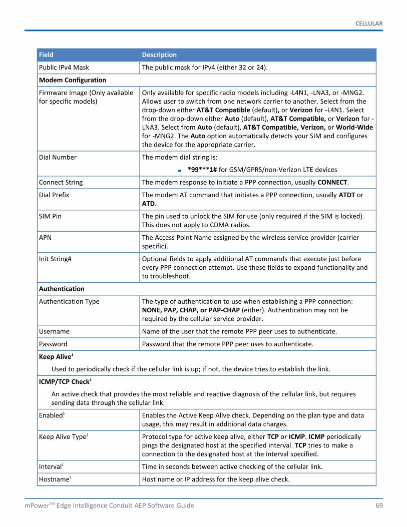
CELLULAR
mPowerTM Edge Intelligence Conduit AEP Software Guide 69
Field Description
Public IPv4 Mask The public mask for IPv4 (either 32 or 24).
Modem Configuration
Firmware Image (Only availablefor specific models)
Only available for specific radio models including -L4N1, -LNA3, or -MNG2.Allows user to switch from one network carrier to another. Select from thedrop-down either AT&T Compatible (default), or Verizon for -L4N1. Selectfrom the drop-down either Auto (default), AT&T Compatible, or Verizon for -LNA3. Select from Auto (default), AT&T Compatible, Verizon, or World-Widefor -MNG2. The Auto option automatically detects your SIM and configuresthe device for the appropriate carrier.
Dial Number The modem dial string is:
*99***1# for GSM/GPRS/non-Verizon LTE devices
Connect String The modem response to initiate a PPP connection, usually CONNECT.
Dial Prefix The modem AT command that initiates a PPP connection, usually ATDT orATD.
SIM Pin The pin used to unlock the SIM for use (only required if the SIM is locked).This does not apply to CDMA radios.
APN The Access Point Name assigned by the wireless service provider (carrierspecific).
Init String# Optional fields to apply additional AT commands that execute just beforeevery PPP connection attempt. Use these fields to expand functionality andto troubleshoot.
Authentication
Authentication Type The type of authentication to use when establishing a PPP connection:NONE, PAP, CHAP, or PAP-CHAP (either). Authentication may not berequired by the cellular service provider.
Username Name of the user that the remote PPP peer uses to authenticate.
Password Password that the remote PPP peer uses to authenticate.
Keep Alive1
Used to periodically check if the cellular link is up; if not, the device tries to establish the link.
ICMP/TCP Check1
An active check that provides the most reliable and reactive diagnosis of the cellular link, but requiressending data through the cellular link.
Enabled1 Enables the Active Keep Alive check. Depending on the plan type and datausage, this may result in additional data charges.
Keep Alive Type1 Protocol type for active keep alive, either TCP or ICMP. ICMP periodicallypings the designated host at the specified interval. TCP tries to make aconnection to the designated host at the interval specified.
Interval1 Time in seconds between active checking of the cellular link.
Hostname1 Host name or IP address for the keep alive check.
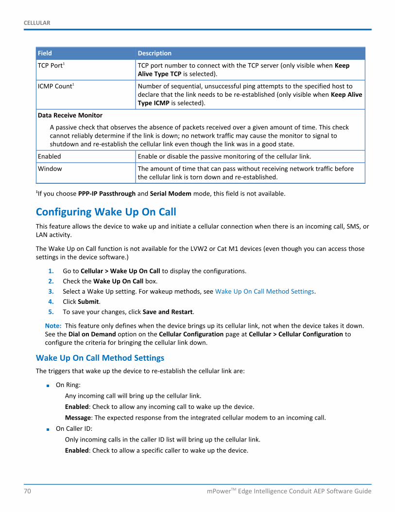
CELLULAR
70 mPowerTM Edge Intelligence Conduit AEP Software Guide
Field Description
TCP Port1 TCP port number to connect with the TCP server (only visible when KeepAlive Type TCP is selected).
ICMP Count1 Number of sequential, unsuccessful ping attempts to the specified host todeclare that the link needs to be re-established (only visible when Keep AliveType ICMP is selected).
Data Receive Monitor
A passive check that observes the absence of packets received over a given amount of time. This checkcannot reliably determine if the link is down; no network traffic may cause the monitor to signal toshutdown and re-establish the cellular link even though the link was in a good state.
Enabled Enable or disable the passive monitoring of the cellular link.
Window The amount of time that can pass without receiving network traffic beforethe cellular link is torn down and re-established.
1If you choose PPP-IP Passthrough and Serial Modem mode, this field is not available.
Configuring Wake Up On CallThis feature allows the device to wake up and initiate a cellular connection when there is an incoming call, SMS, orLAN activity.
The Wake Up on Call function is not available for the LVW2 or Cat M1 devices (even though you can access thosesettings in the device software.)
1. Go to Cellular > Wake Up On Call to display the configurations.2. Check the Wake Up On Call box.3. Select a Wake Up setting. For wakeup methods, see Wake Up On Call Method Settings.4. Click Submit.5. To save your changes, click Save and Restart.
Note: This feature only defines when the device brings up its cellular link, not when the device takes it down.See the Dial on Demand option on the Cellular Configuration page at Cellular > Cellular Configuration toconfigure the criteria for bringing the cellular link down.
Wake Up On Call Method SettingsThe triggers that wake up the device to re-establish the cellular link are:
On Ring:Any incoming call will bring up the cellular link.Enabled: Check to allow any incoming call to wake up the device.Message: The expected response from the integrated cellular modem to an incoming call.
On Caller ID:Only incoming calls in the caller ID list will bring up the cellular link.Enabled: Check to allow a specific caller to wake up the device.
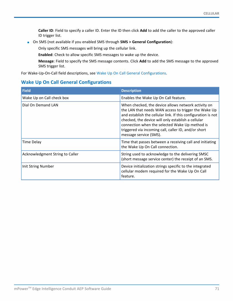
CELLULAR
mPowerTM Edge Intelligence Conduit AEP Software Guide 71
Caller ID: Field to specify a caller ID. Enter the ID then click Add to add the caller to the approved callerID trigger list.
On SMS (not available if you enabled SMS through SMS > General Configuration):Only specific SMS messages will bring up the cellular link.Enabled: Check to allow specific SMS messages to wake up the device.Message: Field to specify the SMS message contents. Click Add to add the SMS message to the approvedSMS trigger list.
For Wake-Up-On-Call field descriptions, see Wake Up On Call General Configurations.
Wake Up On Call General ConfigurationsField Description
Wake Up on Call check box Enables the Wake Up On Call feature.
Dial On Demand LAN When checked, the device allows network activity onthe LAN that needs WAN access to trigger the Wake Upand establish the cellular link. If this configuration is notchecked, the device will only establish a cellularconnection when the selected Wake Up method istriggered via incoming call, caller ID, and/or shortmessage service (SMS).
Time Delay Time that passes between a receiving call and initiatingthe Wake Up On Call connection.
Acknowledgment String to Caller String used to acknowledge to the delivering SMSC(short message service center) the receipt of an SMS.
Init String Number Device initialization strings specific to the integratedcellular modem required for the Wake Up On Callfeature.
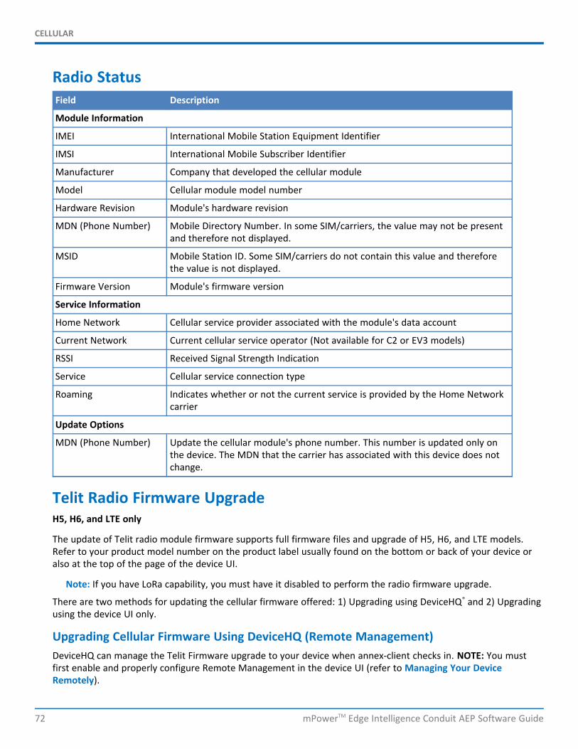
CELLULAR
72 mPowerTM Edge Intelligence Conduit AEP Software Guide
Radio StatusField Description
Module Information
IMEI International Mobile Station Equipment Identifier
IMSI International Mobile Subscriber Identifier
Manufacturer Company that developed the cellular module
Model Cellular module model number
Hardware Revision Module's hardware revision
MDN (Phone Number) Mobile Directory Number. In some SIM/carriers, the value may not be presentand therefore not displayed.
MSID Mobile Station ID. Some SIM/carriers do not contain this value and thereforethe value is not displayed.
Firmware Version Module's firmware version
Service Information
Home Network Cellular service provider associated with the module's data account
Current Network Current cellular service operator (Not available for C2 or EV3 models)
RSSI Received Signal Strength Indication
Service Cellular service connection type
Roaming Indicates whether or not the current service is provided by the Home Networkcarrier
Update Options
MDN (Phone Number) Update the cellular module's phone number. This number is updated only onthe device. The MDN that the carrier has associated with this device does notchange.
Telit Radio Firmware UpgradeH5, H6, and LTE only
The update of Telit radio module firmware supports full firmware files and upgrade of H5, H6, and LTE models.Refer to your product model number on the product label usually found on the bottom or back of your device oralso at the top of the page of the device UI.
Note: If you have LoRa capability, you must have it disabled to perform the radio firmware upgrade.
There are two methods for updating the cellular firmware offered: 1) Upgrading using DeviceHQ® and 2) Upgradingusing the device UI only.
Upgrading Cellular Firmware Using DeviceHQ (Remote Management)DeviceHQ can manage the Telit Firmware upgrade to your device when annex-client checks in. NOTE: You mustfirst enable and properly configure Remote Management in the device UI (refer to Managing Your DeviceRemotely).
CELLULAR
mPowerTM Edge Intelligence Conduit AEP Software Guide 73
1. Open DeviceHQ.2. Select Device > Your Device Name > Schedule > Upgrade Radio Firmware.3. DeviceHQ provides a list of eligible Telit module firmware that a particular device can queue for
download and install. Select the appropriate firmware.4. The device checks in, downloads the firmware, automatically verifies the MD5 sum of the firmware to
check the integrity of the upgrade file, and applies it to the modem module.Note: Allow at least 10 minutes after the device has downloaded the firmware file before taking anyaction. The system should reboot on its own after a successful download. Otherwise, after 10 minutes,you may reboot the device manually.
5. Once you have refreshed or the device checks in again, verify that the cellular radio firmware has beenupdated in DeviceHQ.
In the device UI, you can also check that the cellular radio firmware has been updated. Refer to the Current RadioFirmware on the Telit Radio Firmware Upgrade page (see step 1 of Upgrading Cellular Firmware Using UI only) oralso see the firmware version on the Radio Status page under Cellular.
Upgrading Cellular Firmware using UI onlyYou can also use the device UI to upgrade your Telit Firmware. You must first obtain the appropriate binaryupgrade file for the cellular radio in your device.
NOTE: If you use the firmware upgrade via Cellular using the UI and you get a timeout failure, first try to boost thesignal strength and attempt it again. Otherwise, update via an Ethernet connection or use DeviceHQ.
1. Open the Telit Radio Firmware Upgrade page on the device. The page is not available through thestandard UI. Enter the IP address/URL manually: https://<Device-IP>/upload_radio_firmware (usuallyyour device IP address is the default address unless you changed it).
2. Find the upgrade zip file in your product page under Downloads on www.multitech.com. (The file namestarts with stream.) Download the zip file from the website and save it on your local computer. Extractthe binary upgrade file and MD5 file.
3. Enter the MD5 Check Sum or hash under File MD5.4. Browse for the file and select it.5. Click Start Upgrade. The system should reboot automatically after a successful download. Otherwise,
after 10 minutes, you may reboot the device manually.6. Check that the cellular radio firmware has been updated. Refer to the Current Radio Firmware on the
Telit Radio Firmware Upgrade page (see step 1 of Upgrading Cellular Firmware Using UI only) or also seethe firmware version on the Radio Status page under Cellular.
SMS
74 mPowerTM Edge Intelligence Conduit AEP Software Guide
Chapter 9 – SMSConfiguring SMSThis function is not available if you enable SMS through Cellular > Wake Up On Call. To enable short messageservice (SMS) via the Web Management interface or API:
1. From the Web Management interface, go to SMS > SMS Configuration > SMS Settings.2. Check Enabled.3. In the Sent SMS to Keep field, enter the total number of sent SMS messages to keep in the device's
history.4. In the Received SMS to Keep field, enter the total number of received SMS messages to keep in the
device's history.5. In the Resend Failed SMS field, enter the total number of resend attempts for SMS messages that failed
to send.6. Set messages to keep and resend options.7. Click Submit.8. To save your changes, click Save and Restart.
For field descriptions see SMS Field Descriptions.
SMS Field DescriptionsField Description
Enabled Enables the SMS utilities required to send SMS via API and the Web Managementinterface.
Sent SMS to Keep The total number of sent SMS messages to keep in the device's history.
Received SMS to Keep The total number of received SMS messages to keep in the device's history.
Resend Failed SMS The total number of resend attempts for SMS messages that failed to send.
SMS CommandsSMS commands are disabled by default.
First, make sure to enable SMS under SMS > SMS Configuration > SMS Settings.
To enable these available commands (for status and debugging purposes) and set security filters:
1. Go to SMS > SMS Configuration > SMS Commands, check the SMS commands you wish to enable. Referto the table of SMS Command Descriptions for details on available commands.
2. Check the security filters, you wish to use (can be one or both):Password: If enabled, SMS commands will require p password in the syntax. For example: p123456 #serial where 123456 is your password.
Use the default password (last six digits of the radio's IMEI or last six digits of theMEID).Or click on Use custom password and enter your own password.You can also toggle the eye icon to make the password visible or hidden.
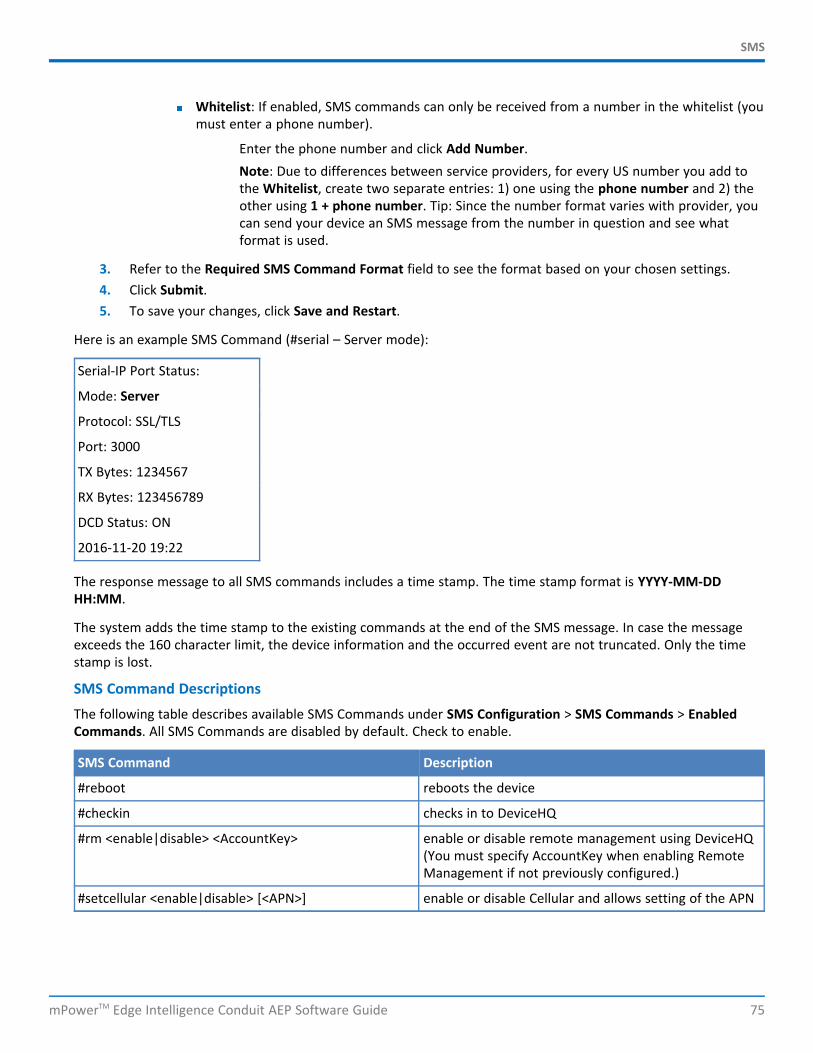
SMS
mPowerTM Edge Intelligence Conduit AEP Software Guide 75
Whitelist: If enabled, SMS commands can only be received from a number in the whitelist (youmust enter a phone number).
Enter the phone number and click Add Number.Note: Due to differences between service providers, for every US number you add tothe Whitelist, create two separate entries: 1) one using the phone number and 2) theother using 1 + phone number. Tip: Since the number format varies with provider, youcan send your device an SMS message from the number in question and see whatformat is used.
3. Refer to the Required SMS Command Format field to see the format based on your chosen settings.4. Click Submit.5. To save your changes, click Save and Restart.
Here is an example SMS Command (#serial – Server mode):
Serial-IP Port Status:
Mode: Server
Protocol: SSL/TLS
Port: 3000
TX Bytes: 1234567
RX Bytes: 123456789
DCD Status: ON
2016-11-20 19:22
The response message to all SMS commands includes a time stamp. The time stamp format is YYYY-MM-DDHH:MM.
The system adds the time stamp to the existing commands at the end of the SMS message. In case the messageexceeds the 160 character limit, the device information and the occurred event are not truncated. Only the timestamp is lost.
SMS Command DescriptionsThe following table describes available SMS Commands under SMS Configuration > SMS Commands > EnabledCommands. All SMS Commands are disabled by default. Check to enable.
SMS Command Description
#reboot reboots the device
#checkin checks in to DeviceHQ
#rm <enable|disable> <AccountKey> enable or disable remote management using DeviceHQ(You must specify AccountKey when enabling RemoteManagement if not previously configured.)
#setcellular <enable|disable> [<APN>] enable or disable Cellular and allows setting of the APN
SMS
76 mPowerTM Edge Intelligence Conduit AEP Software Guide
SMS Command Description
#ping [<interface>] [<count>] <address> ping IP address <count> times (range: 1-20, default = 4)through <interface> (choose from cellular, wifi, andethernet or if not specified, the default gatewayinterface is used)
#apn get APN string
#cellular PPP status
#radio radio status
#ethernet Ethernet LAN configuration details
#wan WAN transport type and WAN priority configuration
#serial get serial details: Mode (Server or Client), RX bytes, TXbytes, DCD Status, Protocol, Port (Server mode only),Server IP Address (Client mode only), and Server Port(Client Mode only)
#wifi get Wi-Fi details: Date and time in format YYYY-MM-DDHH:MM, mode (WAN or Access Point), MAC address,status (for WAN mode only), SSID, Security settings (forAccess Point only, None, WEP, WPA, WPA2-PSK, andWPA/WPA2-PSK)
#geoposition Upon reception, the device sends back its GPScoordinates, latitude and longitude, as an SMS textmessage (only available on devices with a GPS module)
#lnsrestart Upon reception, the device restarts the LoRa networkserver
Note: Arguments in square brackets [ ] are optional. Those in angle brackets < > are values.
Sending an SMS MessageTo send an SMS message from the device:
1. Go to SMS > Send SMS to display the Send SMS window.2. In the Recipient field, enter a phone number and click Add. You can add up to 100 phone numbers.3. In the Message field, enter a text message up to 160 characters long.4. Click Send. The system displays a confirmation indicating whether the message has been successfully sent
or not.
Viewing Received SMS MessagesTo view received SMS messages from the device:
1. Go to SMS > Received to display the Received SMS window. The messages are sorted by date with themost recent messages on top. The table shows up to 30 characters for each message.
2. To view the full message, click the eye icon to the right of the message entry.
SMS
mPowerTM Edge Intelligence Conduit AEP Software Guide 77
3. To delete an SMS message, click the trash can icon under Options to the right of the message. A dialogbox asks you to confirm that you want to delete the SMS message. Click OK.
4. To delete all the received SMS messages, click Delete All. A dialog box asks you to confirm that you wantto delete all SMS messages. Click OK.
5. To configure, the receive list to automatically update, check the Auto Refresh box in the upper rightcorner.
Viewing Sent SMS MessagesTo view sent SMS messages from the device:
1. Go to SMS > Sent to display the Sent SMS window. The messages are sorted by date with the mostrecent messages on top. The table shows up to 30 characters for each message.
2. To view a full message, click the eye icon to the right of the message entry.3. To delete a sent SMS message, click the trash can icon to the right of the message entry. A dialog box
asks you to confirm that you want to delete the SMS message. Click OK.4. To delete all the sent SMS messages, click Delete All. A dialog box asks you to confirm that you want to
delete all the SMS messages. Click OK.5. To configure, the receive list to automatically update, check the Auto Refresh box in the upper right
corner.
TUNNELS
78 mPowerTM Edge Intelligence Conduit AEP Software Guide
Chapter 10 – TunnelsSetting Up GRE TunnelsTunneling allows the use of a public network to convey data on behalf of two remote private networks. It is also away to transform data frames to allow them to pass networks with incompatible address spaces or evenincompatible protocols. Generic Routing Encapsulation (GRE) is a tunneling mechanism that uses IP as thetransport protocol and can be used for carrying many different passenger protocols.
The tunnels behave as virtual point-to-point links that have two endpoints identified by the tunnel source andtunnel destination addresses at each endpoint. Configuring a GRE tunnel involves creating a tunnel interface, whichis a logical interface, then configuring the tunnel endpoints for the tunnel interface. To set up GRE tunnels:
1. From the Web Management interface, go to Tunnels > GRE Tunnels.2. Click Add Tunnel.3. In the Tunnel Name field, enter a name for the new tunnel.4. (Optional) In the Description field, you can enter a description that helps you further identify the tunnel.5. In the GRE Tunnel Settings section:
a. In the Remote WAN IP field, type the IP address of the gateway to which you want to connect.b. Click Add in the Remote Network Routes table.c. In the Remote Network Route field, type the IP address of the network that is routed through the
tunnel.d. In the Remote Network Mask field, type the mask of the network.e. Click Add. The defined Remote Network Route is added and appears in the Network Routes list.
6. (Optional) In the Checking period (minutes) specify the interval to resolve the Remote WAN hostname byDynDNS. Recommended for hostnames that have dynamic IP addresses.
7. Click Submit.8. The defined GRE tunnel configuration is added and appears in the GRE Tunnels list.9. To save your changes, click Save and Restart.
Configuring Network-to-Network Virtual Private Networks (VPNs)IPsec Tunnels
The device supports site-to-site VPNs via IPsec tunnels for secure network-to-network communication. Both tunnelendpoints should have static public IP addresses and must be able to agree on the encryption and authenticationmethods to use. Setting up an IPsec tunnel is a two-stage negotiation process. The first stage negotiates how thekey exchange is protected. The second stage negotiates how the data passing through the tunnel is protected. Forendpoints that do not have public static IP addresses, additional options may help such as NAT Traversal andAggressive Mode.
By default, based on the encryption method chosen, the device negotiates ISAKMP hash and group policies from adefault set of secure algorithms with no known vulnerabilities. This allows flexibility in establishing connectionswith remote endpoints. There is an ADVANCED mode that provides a way to specify a strict set of algorithms touse per phase, limiting the remote endpoint's negotiation options.
The default set of Hash Algorithms is: SHA-1, SHA-2, and MD5.
TUNNELS
mPowerTM Edge Intelligence Conduit AEP Software Guide 79
The default set of DH Group Algorithms is: DH2(1024-bit), DH5(1536-bit), DH14(2048-bit), DH15(3072-bit),DH16(4096-bit), DH17(6144-bit), DH18(8192-bit), DH22(1024-bit), DH23(2048-bit), and DH24(2048-bit).
To set up a Network-to-Network VPN tunnel on your device:
1. From the Web Management interface, go to Tunnels > IPsec Tunnels.2. Click Add Tunnel in upper right.3. Enter a Name for the tunnel and an optional Description.4. Click Next. The IPsec Remote Tunnel Endpoint pane opens.5. Enter a network manually by entering the Remote Network Route (LAN IP) and Remote Network Mask
(Subnet).6. Choose Tunnel Type from the drop-down. Values are IKE and IKEv2.7. The public IP address and LAN of this device do not need to be configured because they are already
known by this device.8. Select the Authentication Method from the drop-down either Pre-Shared Key or RSA Signatures.
Authentication is performed using secret pre-shared keys and hashing algorithms (like SHA1 MD5) or RSAsignatures.
9. If you select Pre-Shared Key, then enter theSecret. This key needs to be the same on both endpoints.10. If you select RSA Signatures, enter the following (in .pem format):
a. CA Certificateb. Local RSA Certificatec. Local RSA Private Key
11. Select the Encryption Method from the drop-down including 3DES, AES-128, AES-192, AES-256 , orADVANCED. The encryption method needs to be the same on both endpoints. IKE encryption algorithm isused for the connection (phase 1 - ISAKMP SA). Based off of phase 1, a secure set of defaults are used forphase 2, unless you use the Advanced option, in which case, you must specify all components of bothphases 1 and 2 including Encryption, Authentication, and Key Group.
12. If the remote endpoint is set up with unique IDs, check the Enable UID box, and enter the Local andRemote IDs.
13. Click Show for IPSec Tunnel: Advanced features that limit the remote endpoint's negotiation options.14. In the IKE Lifetime field, enter the duration in which ISAKMP SA lasts (in hours).15. In the Max Retries field, enter the number of retries for the IPSec Tunnel. Enter zero for unlimited retries.16. In the Key Life field, duration in which the IPSec SA lasts (in hours).17. In the Checking Period field, enter the timeout interval (in minutes).18. Check Compression to enable IPComp (compression algorithm).19. Check Aggressive Mode to enable exchange identification in plain text (unencrypted for faster
negotiation). NOTE: This mode is less secure and prone to dictionary and brute force attacks.20. Click Submit.21. To save your changes, click Save and Restart.
For field descriptions, see IPsec Tunnel Configuration Field Descriptions.
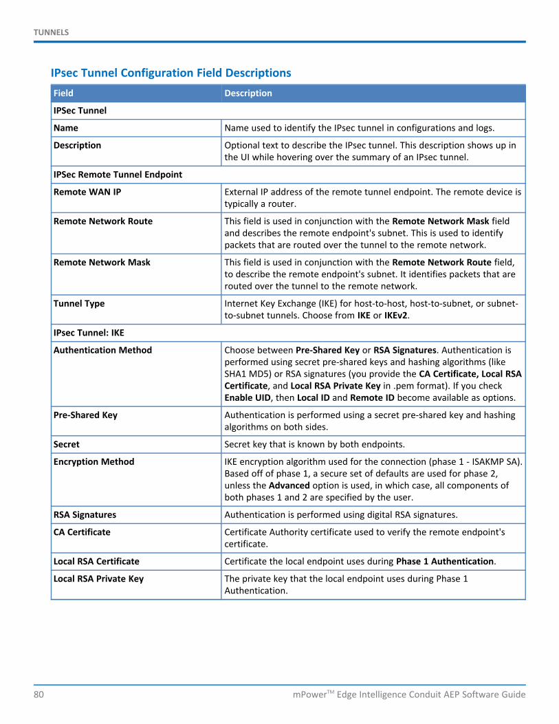
TUNNELS
80 mPowerTM Edge Intelligence Conduit AEP Software Guide
IPsec Tunnel Configuration Field DescriptionsField Description
IPSec Tunnel
Name Name used to identify the IPsec tunnel in configurations and logs.
Description Optional text to describe the IPsec tunnel. This description shows up inthe UI while hovering over the summary of an IPsec tunnel.
IPSec Remote Tunnel Endpoint
Remote WAN IP External IP address of the remote tunnel endpoint. The remote device istypically a router.
Remote Network Route This field is used in conjunction with the Remote Network Mask fieldand describes the remote endpoint's subnet. This is used to identifypackets that are routed over the tunnel to the remote network.
Remote Network Mask This field is used in conjunction with the Remote Network Route field,to describe the remote endpoint's subnet. It identifies packets that arerouted over the tunnel to the remote network.
Tunnel Type Internet Key Exchange (IKE) for host-to-host, host-to-subnet, or subnet-to-subnet tunnels. Choose from IKE or IKEv2.
IPsec Tunnel: IKE
Authentication Method Choose between Pre-Shared Key or RSA Signatures. Authentication isperformed using secret pre-shared keys and hashing algorithms (likeSHA1 MD5) or RSA signatures (you provide the CA Certificate, Local RSACertificate, and Local RSA Private Key in .pem format). If you checkEnable UID, then Local ID and Remote ID become available as options.
Pre-Shared Key Authentication is performed using a secret pre-shared key and hashingalgorithms on both sides.
Secret Secret key that is known by both endpoints.
Encryption Method IKE encryption algorithm used for the connection (phase 1 - ISAKMP SA).Based off of phase 1, a secure set of defaults are used for phase 2,unless the Advanced option is used, in which case, all components ofboth phases 1 and 2 are specified by the user.
RSA Signatures Authentication is performed using digital RSA signatures.
CA Certificate Certificate Authority certificate used to verify the remote endpoint'scertificate.
Local RSA Certificate Certificate the local endpoint uses during Phase 1 Authentication.
Local RSA Private Key The private key that the local endpoint uses during Phase 1Authentication.
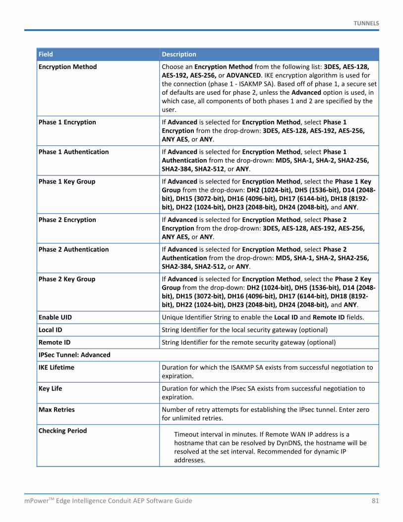
TUNNELS
mPowerTM Edge Intelligence Conduit AEP Software Guide 81
Field Description
Encryption Method Choose an Encryption Method from the following list: 3DES, AES-128,AES-192, AES-256, or ADVANCED. IKE encryption algorithm is used forthe connection (phase 1 - ISAKMP SA). Based off of phase 1, a secure setof defaults are used for phase 2, unless the Advanced option is used, inwhich case, all components of both phases 1 and 2 are specified by theuser.
Phase 1 Encryption If Advanced is selected for Encryption Method, select Phase 1Encryption from the drop-drown: 3DES, AES-128, AES-192, AES-256,ANY AES, or ANY.
Phase 1 Authentication If Advanced is selected for Encryption Method, select Phase 1Authentication from the drop-drown: MD5, SHA-1, SHA-2, SHA2-256,SHA2-384, SHA2-512, or ANY.
Phase 1 Key Group If Advanced is selected for Encryption Method, select the Phase 1 KeyGroup from the drop-down: DH2 (1024-bit), DH5 (1536-bit), D14 (2048-bit), DH15 (3072-bit), DH16 (4096-bit), DH17 (6144-bit), DH18 (8192-bit), DH22 (1024-bit), DH23 (2048-bit), DH24 (2048-bit), and ANY.
Phase 2 Encryption If Advanced is selected for Encryption Method, select Phase 2Encryption from the drop-drown: 3DES, AES-128, AES-192, AES-256,ANY AES, or ANY.
Phase 2 Authentication If Advanced is selected for Encryption Method, select Phase 2Authentication from the drop-drown: MD5, SHA-1, SHA-2, SHA2-256,SHA2-384, SHA2-512, or ANY.
Phase 2 Key Group If Advanced is selected for Encryption Method, select the Phase 2 KeyGroup from the drop-down: DH2 (1024-bit), DH5 (1536-bit), D14 (2048-bit), DH15 (3072-bit), DH16 (4096-bit), DH17 (6144-bit), DH18 (8192-bit), DH22 (1024-bit), DH23 (2048-bit), DH24 (2048-bit), and ANY.
Enable UID Unique Identifier String to enable the Local ID and Remote ID fields.
Local ID String Identifier for the local security gateway (optional)
Remote ID String Identifier for the remote security gateway (optional)
IPSec Tunnel: Advanced
IKE Lifetime Duration for which the ISAKMP SA exists from successful negotiation toexpiration.
Key Life Duration for which the IPsec SA exists from successful negotiation toexpiration.
Max Retries Number of retry attempts for establishing the IPsec tunnel. Enter zerofor unlimited retries.
Checking Period Timeout interval in minutes. If Remote WAN IP address is ahostname that can be resolved by DynDNS, the hostname will beresolved at the set interval. Recommended for dynamic IPaddresses.
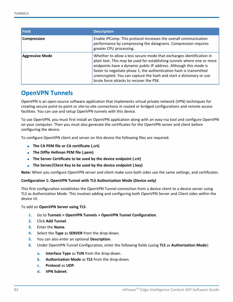
TUNNELS
82 mPowerTM Edge Intelligence Conduit AEP Software Guide
Field Description
Compression Enable IPComp. This protocol increases the overall communicationperformance by compressing the datagrams. Compression requiresgreater CPU processing.
Aggressive Mode Whether to allow a less secure mode that exchanges identification inplain text. This may be used for establishing tunnels where one or moreendpoints have a dynamic public IP address. Although this mode isfaster to negotiate phase 1, the authentication hash is transmittedunencrypted. You can capture the hash and start a dictionary or usebrute force attacks to recover the PSK.
OpenVPN TunnelsOpenVPN is an open-source software application that implements virtual private network (VPN) techniques forcreating secure point-to-point or site-to-site connections in routed or bridged configurations and remote accessfacilities. You can use and setup OpenVPN tunnels with this device.
To use OpenVPN, you must first install an OpenVPN application along with an easy-rsa tool and configure OpenVPNon your computer. Then you must also generate the certificates for the OpenVPN server and client beforeconfiguring the device.
To configure OpenVPN client and server on this device the following files are required:
The CA PEM file or CA certificate (.crt)The Diffie Hellman PEM file (.pem)The Server Certificate to be used by the device endpoint (.crt)The Server/Client Key to be used by the device endpoint (.key)
Note: When you configure OpenVPN server and client make sure both sides use the same settings, and certificates.
Configuration 1: OpenVPN Tunnel with TLS Authorization Mode (Device only)
This first configuration establishes the OpenVPN Tunnel connection from a device client to a device server usingTLS as Authorization Mode. This involves adding and configuring both OpenVPN Server and Client sides within thedevice UI.
To add an OpenVPN Server using TLS:
1. Go to Tunnels > OpenVPN Tunnels > OpenVPN Tunnel Configuration.2. Click Add Tunnel.3. Enter the Name.4. Select the Type as SERVER from the drop-down.5. You can also enter an optional Description.6. Under OpenVPN Tunnel Configuration, enter the following fields (using TLS as Authorization Mode):
a. Interface Type as TUN from the drop-down.b. Authorization Mode as TLS from the drop-down.c. Protocol as UDP.d. VPN Subnet.

TUNNELS
mPowerTM Edge Intelligence Conduit AEP Software Guide 83
e. Port number.f. VPN Netmask.g. LZO Compression as ADAPTIVE from the drop-down.h. Hash Algorithm as DEFAULT.i. Encryption Cipher as DEFAULT.j. Min. TLS Version as 1.2.k. TLS Cipher Suite as DEFAULT as 1.2.l. Enter the contents of the following files generated from the easy-rsa tool. You can copy and paste
this content from the certificate files after opening from a text editor like Notepad. (all required):
i. CA PEM (.crt)ii. Diffie Hellman PEM (.pem)iii. Server Certificate PEM (.crt)iv. Server Key PEM (.key)
Note: Use the same CA PEM certificate and parameters as the server for the OpenVPN clients .
7. Remote Network Routes create a route from the server network to the client network. This allows theserver to get access to the client’s network. In the OpenVPN Tunnel Network Routes, click Add:
a. Enter the Remote Network Route (should be the client subnet). For example, if the client IP addressis 192.168.3.1, enter 192.168.3.0.
b. Enter the Remote Network Mask (usually 255.255.255.0).c. You may enter Gateway (optional).d. Click Add.
8. The system displays your recently-added Push Route with the client subnet (remote network route +mask).
9. Push Routes create a route from client’s network to the server’s network. This allows clients to get accessto the server’s network. Under Push Routes:
a. Click Client To Client box if you want this optional feature (this establishes a connection betweenmultiple clients that are connected to the server).
b. In the Push Network Route, click Add.c. In the dialog box, enter the Remote Network Route (same address as the server subnet above).d. Enter the Remote Network Mask (same as above).e. You may enter Gateway (optional).f. Click Add.
Note: If you use Static Key Authorization Mode, the Push Routes do not work.
10. The system displays your recently-added Push Route with the client subnet (remote network route +mask).
11. Click Preview to view the tunnel configuration.12. Click Submit.13. Click Save and Restart to save your changes
To add an OpenVPN Client using TLS:
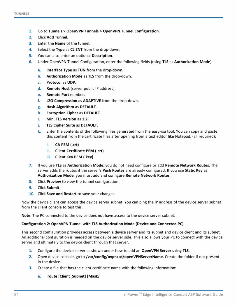
TUNNELS
84 mPowerTM Edge Intelligence Conduit AEP Software Guide
1. Go to Tunnels > OpenVPN Tunnels > OpenVPN Tunnel Configuration.2. Click Add Tunnel.3. Enter the Name of the tunnel.4. Select the Type as CLIENT from the drop-down.5. You can also enter an optional Description.6. Under OpenVPN Tunnel Configuration, enter the following fields (using TLS as Authorization Mode):
a. Interface Type as TUN from the drop-down.b. Authorization Mode as TLS from the drop-down.c. Protocol as UDP.d. Remote Host (server public IP address).e. Remote Port number.f. LZO Compression as ADAPTIVE from the drop-down.g. Hash Algorithm as DEFAULT.h. Encryption Cipher as DEFAULT.i. Min. TLS Version as 1.2.j. TLS Cipher Suite as DEFAULT.k. Enter the contents of the following files generated from the easy-rsa tool. You can copy and paste
this content from the certificate files after opening from a text editor like Notepad. (all required):
i. CA PEM (.crt)ii. Client Certificate PEM (.crt)iii. Client Key PEM (.key)
7. If you use TLS as Authorization Mode, you do not need configure or add Remote Network Routes. Theserver adds the routes if the server's Push Routes are already configured. If you use Static Key asAuthorization Mode, you must add and configure Remote Network Routes.
8. Click Preview to view the tunnel configuration.9. Click Submit.10. Click Save and Restart to save your changes.
Now the device client can access the device server subnet. You can ping the IP address of the device server subnetfrom the client console to test this.
Note: The PC connected to the device does not have access to the device server subnet.
Configuration 2: OpenVPN Tunnel with TLS Authorization Mode (Device and Connected PC)
This second configuration provides access between a device server and its subnet and device client and its subnet.An additional configuration is needed on the device server side. This also allows your PC to connect with the deviceserver and ultimately to the device client through that server.
1. Configure the device server as shown under how to add an OpenVPN Server using TLS.2. Open device console, go to /var/config/ovpnccd/openVPNServerName. Create the folder if not present
in the device.3. Create a file that has the client certificate name with the following information:
a. iroute [Client_Subnet] [Mask]
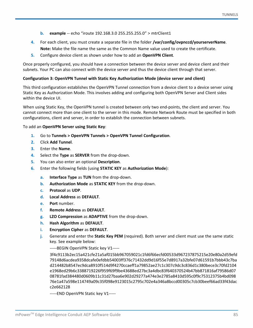
TUNNELS
mPowerTM Edge Intelligence Conduit AEP Software Guide 85
b. example -- echo “iroute 192.168.3.0 255.255.255.0” > mtrClient1
4. For each client, you must create a separate file in the folder /var/config/ovpnccd/yourserverName.Note: Make the file name the same as the Common Name value used to create the certificate.
5. Configure device client as shown under how to add an OpenVPN Client.
Once properly configured, you should have a connection between the device server and device client and theirsubnets. Your PC can also connect with the device server and thus the device client through that server.
Configuration 3: OpenVPN Tunnel with Static Key Authorization Mode (device server and client)
This third configuration establishes the OpenVPN Tunnel connection from a device client to a device server usingStatic Key as Authorization Mode. This involves adding and configuring both OpenVPN Server and Client sideswithin the device UI.
When using Static Key, the OpenVPN tunnel is created between only two end-points, the client and server. Youcannot connect more than one client to the server in this mode. Remote Network Route must be specified in bothconfigurations, client and server, in order to establish the connection between subnets.
To add an OpenVPN Server using Static Key:
1. Go to Tunnels > OpenVPN Tunnels > OpenVPN Tunnel Configuration.2. Click Add Tunnel.3. Enter the Name.4. Select the Type as SERVER from the drop-down.5. You can also enter an optional Description.6. Enter the following fields (using STATIC KEY as Authorization Mode):
a. Interface Type as TUN from the drop-down.b. Authorization Mode as STATIC KEY from the drop-down.c. Protocol as UDP.d. Local Address as DEFAULT.e. Port number.f. Remote Address as DEFAULT.g. LZO Compression as ADAPTIVE from the drop-down.h. Hash Algorithm as DEFAULT.i. Encryption Cipher as DEFAULT.j. Generate and enter the Static Key PEM (required). Both server and client must use the same static
key. See example below:-----BEGIN OpenVPN Static key V1-----3f4c9113b2ec15a421cfe21a5af015bb967059021c1fd6f66ecfd00533d967237875215e20e80a2d59efd79148d6acdea9358dcafe0efdbb54003ff376c71432dd9d16f55e7d8917a32bfe07d61591b7bbb43c7bad214482b8547ec9dca8910f514d9f4270ccaeff1a79852ae27c1c307c9dc3c836d1c380bece3c70fd2104e1968ed29b6c3388719226f959f69f9be43688ed27bc3a4dbc83f640370524b47bb871816af79586d0708781fad384480d0609b11c31d27baa6e902d29277a474e3e2785a8410d595c0f9c75312375b4bd09876e1a47a598e114749a09c35f098e9123015c2795c702e4a346a8bccd00305c7cb30beef66ad33f43dacc2e662128-----END OpenVPN Static key V1-----

TUNNELS
86 mPowerTM Edge Intelligence Conduit AEP Software Guide
7. Remote Network Routes create a route from the server network to the client network. This allows theserver to get access to the client’s network. In the OpenVPN Tunnel Network Routes, click Add:
a. Enter the Remote Network Route (should be the client subnet). For example, if the client IP addressis 192.168.3.1, enter 192.168.3.0.
b. Enter the Remote Network Mask (usually 255.255.255.0).c. Click Add.
8. The system displays your recently-added Remote Network Route with the client subnet (remote networkroute + mask).Note: Push Routes are not required with Static Key as Authorization Mode.
9. Click Preview to view the tunnel configuration.10. Click Submit.11. Click Save and Restart to save your changes.
To add an OpenVPN Client using Static Key:
1. Go to Tunnels > OpenVPN Tunnels > OpenVPN Tunnel Configuration.2. Click Add Tunnel.3. Enter the Name.4. Select the Type as CLIENT from the drop-down.5. You can also enter an optional Description.6. Enter the following fields (using STATIC KEY as Authorization Mode):
a. Interface Type as TUN from the drop-down.b. Authorization Mode as STATIC KEY from the drop-down.c. Protocol as UDP.d. Local Address as DEFAULT.e. Remote Host.f. Remote Address as DEFAULT.g. Remote Port number.h. LZO Compression as ADAPTIVE from the drop-down.i. Select the Encryption Cipher as DEFAULT from drop-down.j. Select the Hash Algorithm as DEFAULT from drop-down.k. Min. TLS Version as 1.2.l. TLS Cipher Suite as DEFAULT.m. Enter the Static Key PEM (required). Both server and client must use the same static key. See
example below:-----BEGIN OpenVPN Static key V1-----3f4c9113b2ec15a421cfe21a5af015bb967059021c1fd6f66ecfd00533d967237875215e20e80a2d59efd79148d6acdea9358dcafe0efdbb54003ff376c71432dd9d16f55e7d8917a32bfe07d61591b7bbb43c7bad214482b8547ec9dca8910f514d9f4270ccaeff1a79852ae27c1c307c9dc3c836d1c380bece3c70fd2104e1968ed29b6c3388719226f959f69f9be43688ed27bc3a4dbc83f640370524b47bb871816af79586d0708781fad384480d0609b11c31d27baa6e902d29277a474e3e2785a8410d595c0f9c75312375b4bd09876e1a47a598e114749a09c35f098e9123015c2795c702e4a346a8bccd00305c7cb30beef66ad33f43dacc2e662128
TUNNELS
mPowerTM Edge Intelligence Conduit AEP Software Guide 87
-----END OpenVPN Static key V1-----.
7. Remote Network Routes create a route from the server network to the client network. This allows theserver to get access to the client’s network. In the OpenVPN Tunnel Network Routes, click Add:
a. Enter the Remote Network Route (should be the client subnet). For example, if the client IP addressis 192.168.3.1, enter 192.168.3.0.
b. Enter the Remote Network Mask (usually 255.255.255.0).c. Click Add.
8. The system displays your recently-added Remote Network Route with the client subnet (remote networkroute + mask).Note: Push Routes are not required with Static Key as Authorization Mode.
9. Click Preview to view the tunnel configuration.10. Click Submit.11. Click Save and Restart to save your changes.
Configuration 4: OpenVPN Tunnel with Static Key Authorization Mode and TCP
This fourth configuration establishes the OpenVPN Tunnel connection from a device client to a device server usingStatic Key as Authorization Mode and TCP protocol (instead of UDP for the third configuration). This involvesadding and configuring both OpenVPN Server and Client sides within the device UI.
To add an OpenVPN Server using Static Key and TCP:
1. Go to Tunnels > OpenVPN Tunnels > OpenVPN Tunnel Configuration.2. Click Add Tunnel.3. Enter the Name.4. Select the Type as SERVER from the drop-down.5. You can also enter an optional Description.6. Enter the following fields (using STATIC KEY as Authorization Mode):
a. Interface Type as TUN from the drop-down.b. Authorization Mode as STATIC KEY from the drop-down.c. Protocol as TCP.d. Local Address as DEFAULT.e. Port number.f. Remote Address as DEFAULT.g. Hash Algorithm as ECDSA-WITH-SHA1.h. LZO Compression as ADAPTIVE from the drop-down.i. Encryption Cipher as CAMELLIA-256-CBC.j. Min. TLS Version as NONE.k. TLS Cipher Suite as DEFAULT.l. Generate and enter the Static Key PEM (required). Both server and client must use the same static
key. See example below:-----BEGIN OpenVPN Static key V1-----3f4c9113b2ec15a421cfe21a5af015bb967059021c1fd6f66ecfd00533d967237875215e20e80a2d59efd79148d6acdea9358dcafe0efdbb54003ff376c71432dd9d16f55e7d8917a32bfe07d61591b7bbb43c7ba
TUNNELS
88 mPowerTM Edge Intelligence Conduit AEP Software Guide
d214482b8547ec9dca8910f514d9f4270ccaeff1a79852ae27c1c307c9dc3c836d1c380bece3c70fd2104e1968ed29b6c3388719226f959f69f9be43688ed27bc3a4dbc83f640370524b47bb871816af79586d0708781fad384480d0609b11c31d27baa6e902d29277a474e3e2785a8410d595c0f9c75312375b4bd09876e1a47a598e114749a09c35f098e9123015c2795c702e4a346a8bccd00305c7cb30beef66ad33f43dacc2e662128-----END OpenVPN Static key V1-----
7. Click Next.8. Remote Network Routes create a route from the server network to the client network. This allows the
server to get access to the client’s network. In the OpenVPN Tunnel Network Routes, click Add:
a. Enter the Remote Network Route (should be the client subnet). For example, if the client IP addressis 192.168.3.1, enter 192.168.3.0.
b. Enter the Remote Network Mask (usually 255.255.255.0).c. Click Add.
9. The system displays your recently-added Remote Network Route with the client subnet (remote networkroute + mask).Note: Push Routes are not required with Static Key as Authorization Mode.
10. Click Preview to view the tunnel configuration.11. Click Submit.12. Click Save and Restart to save your changes.
To add an OpenVPN Client using Static Key and TCP:
1. Go to Tunnels > OpenVPN Tunnels > OpenVPN Tunnel Configuration.2. Click Add Tunnel.3. Enter the Name.4. Select the Type as CLIENT from the drop-down.5. You can also enter an optional Description.6. Enter the following fields (using STATIC KEY as Authorization Mode):
a. Interface Type as TUN from the drop-down.b. Authorization Mode as STATIC KEY from the drop-down.c. Protocol as TCP.d. Local Address as DEFAULT.e. Remote Host.f. Remote Address as DEFAULT.g. Remote Port number.h. Hash Algorithm as ECDSA-WITH-SHA1.i. LZO Compression as ADAPTIVE from the drop-down.j. Encryption Cipher as CAMELLIA-256-CBC.k. Min. TLS Version as NONE.l. TLS Cipher Suite as DEFAULT.m. Generate and enter the Static Key PEM (required). Both server and client must use the same static
key. See example below:-----BEGIN OpenVPN Static key V1-----

TUNNELS
mPowerTM Edge Intelligence Conduit AEP Software Guide 89
3f4c9113b2ec15a421cfe21a5af015bb967059021c1fd6f66ecfd00533d967237875215e20e80a2d59efd79148d6acdea9358dcafe0efdbb54003ff376c71432dd9d16f55e7d8917a32bfe07d61591b7bbb43c7bad214482b8547ec9dca8910f514d9f4270ccaeff1a79852ae27c1c307c9dc3c836d1c380bece3c70fd2104e1968ed29b6c3388719226f959f69f9be43688ed27bc3a4dbc83f640370524b47bb871816af79586d0708781fad384480d0609b11c31d27baa6e902d29277a474e3e2785a8410d595c0f9c75312375b4bd09876e1a47a598e114749a09c35f098e9123015c2795c702e4a346a8bccd00305c7cb30beef66ad33f43dacc2e662128-----END OpenVPN Static key V1-----
7. Click Next.8. Remote Network Routes create a route from the server network to the client network. This allows the
server to get access to the client’s network. In the OpenVPN Tunnel Network Routes, click Add:
a. Enter the Remote Network Route (should be the client subnet). For example, if the client IP addressis 192.168.3.1, enter 192.168.3.0.
b. Enter the Remote Network Mask (usually 255.255.255.0).c. Click Add.
9. The system displays your recently-added Remote Network Route with the client subnet (remote networkroute + mask).Note: Push Routes are not required with Static Key as Authorization Mode.
10. Click Preview to view the tunnel configuration.11. Click Submit.12. Click Save and Restart to save your changes.

ADMINISTRATION
90 mPowerTM Edge Intelligence Conduit AEP Software Guide
Chapter 11 – AdministrationUser AccountsUse this feature to add user accounts or change the password.
The system offers three roles or user types: administrator, engineer, and monitor. Administrators have full rightsand permissions including change settings on the device. Engineers have read/write privileges and some access tocontrols on the device. Monitors have read-only access. Note: the system automatically checks for a strongpassword and tells you how to improve it.
Username requirements include:
Must be unique.Is case-sensitive (for example, admin and ADMIN are treated as two different usernames).Acceptable characters: uppercase alphabetic, lowercase alphabetic, numeric, and non-alphanumeric(symbols like #).A hyphen (-) should not be used as the first character.
Password requirements include:
User account is disabled if password is not set up.Must be at least eight characters in length.Contains three or more different types of characters such as: uppercase alphabetic, lowercase alphabetic,numeric, and non-alphanumeric (symbols like #).
Administrator details:
Able to delete any local users. (Engineer and Monitor cannot delete any users.)Able to modify any other user details, except username.Can not modify another administrator user account if it is the only enabled local administrator user on thedevice.Able to modify own account details except Role, Username, and Enabled values.Able to disable and enable any local users except their own account. Also, not able to disable local useraccount if this is only local administrator.Able to change own password and other user passwords.
Engineer and Monitor details:
Able to view and modify own user account details except Role, Username, and Enabled values.Access to only their own user account.Not able to delete users.Able to change own password.
To add new users:
1. Go to Administration > User Accounts.2. Click Add New User.3. Under User Details, enter the following fields:
ADMINISTRATION
mPowerTM Edge Intelligence Conduit AEP Software Guide 91
a. Username (required)b. Role (required). Select the user role from the drop-down menu including administrator, engineer, or
monitor.c. First Named. Last Namee. Titlef. Divisiong. Employee Identification
4. Under Contact Information, enter the following fields:
a. Emailb. Addressc. Cityd. Statee. Countryf. Postal Codeg. Work Phoneh. Mobile Phone
5. Click Submit.6. The Change Password page opens. Enter New Password. Click Submit.7. The Change Password page opens. Enter New Password. Click Submit.
If the password is not set up for the new user, the user is disabled until the password is set.
Password ComplexityPassword Complexity Rules allow an administrative user to choose rules and limitations on user passwords. Youcan determine various password parameters such as the minimum length of passwords, upper and lower caserequirements, and characters not permitted.
Before choosing your options, you must first select between two different complexity modes: Default or Credit.
Default mode uses a minimum character length and may require a specific number of characters from each class.But requiring specific classes of characters actually makes brute force attacks easier because it reduces the searchspace.
For this reason, we recommend using Credit mode. This mode grants one credit per password character plus oneextra credit for certain character classes up to their respective extra credit cap. You can still specify a minimumnumber of classes, but the strongest passwords come from their length.
In either mode, you should use longer passwords for increased security.
1. Go to Administration > User Accounts.2. Click Change Password Complexity Rules button.3. Under the Change Password Complexity Rules window, select from the drop-down between Default or
Credit mode.4. For Default mode, you may enter the following:

ADMINISTRATION
92 mPowerTM Edge Intelligence Conduit AEP Software Guide
a. Minimum Password Length (default = 8)b. Minimum Upper Case Characters (default = 0)c. Minimum Lower Case Characters (default = 0)d. Minimum Numeric Characters (default = 0)e. Minimum Special Characters (default = 0)f. Maximum Password Length (default = 64)*g. Characters Not Permitted (enter restricted characters in any order with no separators)
5. For Credit mode, you may enter the following:
a. Minimum Password Credits (default = 8)b. Minimum Character Classes (default = 3)c. Upper Case Extra Credit Cap (default = 0)d. Lower Case Extra Credit Cap (default = 0)e. Numeral Extra Credit Cap (default = 0)f. Special Extra Credit Cap (default = 0)g. Maximum Password Length in number of characters (default = 64)*h. Characters Not Permitted (enter restricted characters in any order with no separators)
* Note: Entering a value of 0 indicates no maximum.
Self-DiagnosticsThe device offers self-diagnostics or periodic monitoring of certain issues such as memory errors or leaks, andsecurity violations by applications. The following self-diagnostic features are available with this device (varies withmodel) :
Security ViolationResource Overuse
This monitoring is intended detect corruption, or help prevent malicious activity. After an event is detected, thesystem disables the cellular radio module, sends an alarm or notification, logs the event, and sends a record of itvia SMS, Email, or to the SNMP server. To receive notifications for specific diagnostic features, configure themunder Administration > Notifications.
For the self-diagnostic features, go to Administration > Self-Diagnostics and refer to the following sections.
To turn on the Resource Overuse diagnostic that detects memory leaks or errors:
1. Check Enabled under Resource Overuse.2. If you want the system to reboot the device after a Resource Overuse is detected, check Reboot the
device under Actions.
To turn on the Security Violation diagnostic that detects security rule violations by applications:
1. Check Enabled under Security Violation.2. If you want the system to disable WAN interfaces after a Security Violation is detected, check Disable
WAN Interfaces under Actions.3. If you want the system to disable user-defined firewall rules after a Security Violation is detected, check
Disable User-Defined Firewall Rules under Actions.
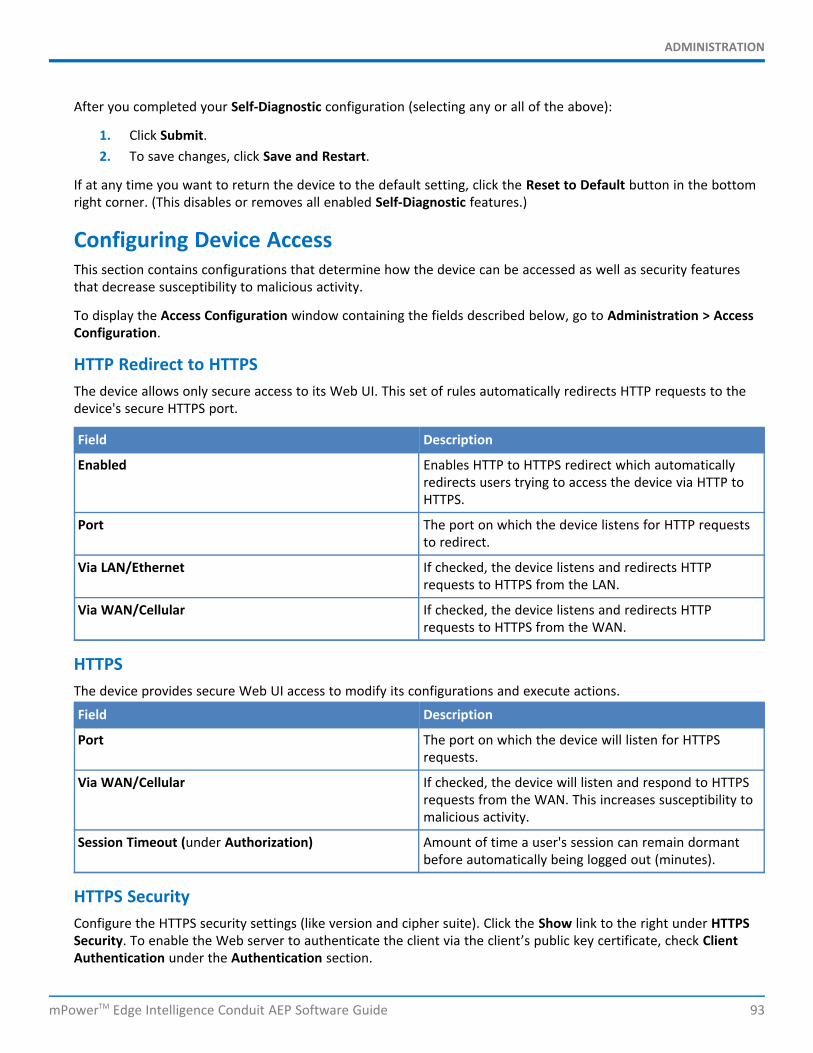
ADMINISTRATION
mPowerTM Edge Intelligence Conduit AEP Software Guide 93
After you completed your Self-Diagnostic configuration (selecting any or all of the above):
1. Click Submit.2. To save changes, click Save and Restart.
If at any time you want to return the device to the default setting, click the Reset to Default button in the bottomright corner. (This disables or removes all enabled Self-Diagnostic features.)
Configuring Device AccessThis section contains configurations that determine how the device can be accessed as well as security featuresthat decrease susceptibility to malicious activity.
To display the Access Configuration window containing the fields described below, go to Administration > AccessConfiguration.
HTTP Redirect to HTTPSThe device allows only secure access to its Web UI. This set of rules automatically redirects HTTP requests to thedevice's secure HTTPS port.
Field Description
Enabled Enables HTTP to HTTPS redirect which automaticallyredirects users trying to access the device via HTTP toHTTPS.
Port The port on which the device listens for HTTP requeststo redirect.
Via LAN/Ethernet If checked, the device listens and redirects HTTPrequests to HTTPS from the LAN.
Via WAN/Cellular If checked, the device listens and redirects HTTPrequests to HTTPS from the WAN.
HTTPSThe device provides secure Web UI access to modify its configurations and execute actions.
Field Description
Port The port on which the device will listen for HTTPSrequests.
Via WAN/Cellular If checked, the device will listen and respond to HTTPSrequests from the WAN. This increases susceptibility tomalicious activity.
Session Timeout (under Authorization) Amount of time a user's session can remain dormantbefore automatically being logged out (minutes).
HTTPS SecurityConfigure the HTTPS security settings (like version and cipher suite). Click the Show link to the right under HTTPSSecurity. To enable the Web server to authenticate the client via the client’s public key certificate, check ClientAuthentication under the Authentication section.
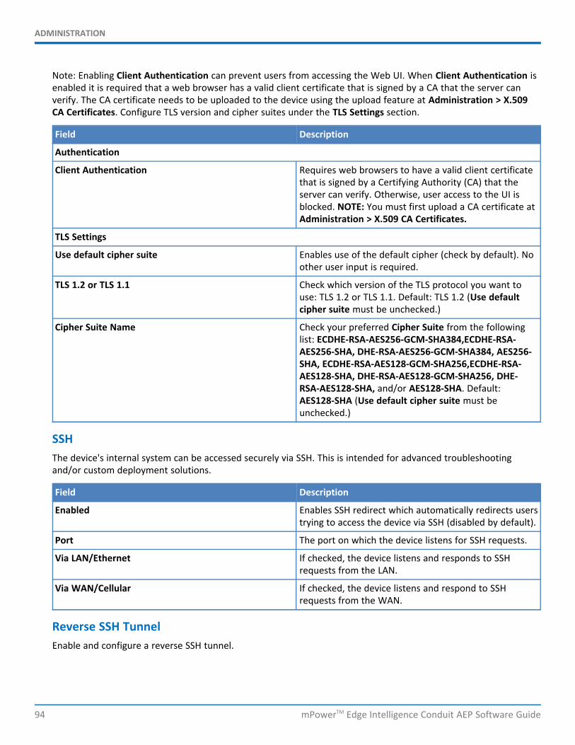
ADMINISTRATION
94 mPowerTM Edge Intelligence Conduit AEP Software Guide
Note: Enabling Client Authentication can prevent users from accessing the Web UI. When Client Authentication isenabled it is required that a web browser has a valid client certificate that is signed by a CA that the server canverify. The CA certificate needs to be uploaded to the device using the upload feature at Administration > X.509CA Certificates. Configure TLS version and cipher suites under the TLS Settings section.
Field Description
Authentication
Client Authentication Requires web browsers to have a valid client certificatethat is signed by a Certifying Authority (CA) that theserver can verify. Otherwise, user access to the UI isblocked. NOTE: You must first upload a CA certificate atAdministration > X.509 CA Certificates.
TLS Settings
Use default cipher suite Enables use of the default cipher (check by default). Noother user input is required.
TLS 1.2 or TLS 1.1 Check which version of the TLS protocol you want touse: TLS 1.2 or TLS 1.1. Default: TLS 1.2 (Use defaultcipher suite must be unchecked.)
Cipher Suite Name Check your preferred Cipher Suite from the followinglist: ECDHE-RSA-AES256-GCM-SHA384,ECDHE-RSA-AES256-SHA, DHE-RSA-AES256-GCM-SHA384, AES256-SHA, ECDHE-RSA-AES128-GCM-SHA256,ECDHE-RSA-AES128-SHA, DHE-RSA-AES128-GCM-SHA256, DHE-RSA-AES128-SHA, and/or AES128-SHA. Default:AES128-SHA (Use default cipher suite must beunchecked.)
SSHThe device's internal system can be accessed securely via SSH. This is intended for advanced troubleshootingand/or custom deployment solutions.
Field Description
Enabled Enables SSH redirect which automatically redirects userstrying to access the device via SSH (disabled by default).
Port The port on which the device listens for SSH requests.
Via LAN/Ethernet If checked, the device listens and responds to SSHrequests from the LAN.
Via WAN/Cellular If checked, the device listens and respond to SSHrequests from the WAN.
Reverse SSH TunnelEnable and configure a reverse SSH tunnel.
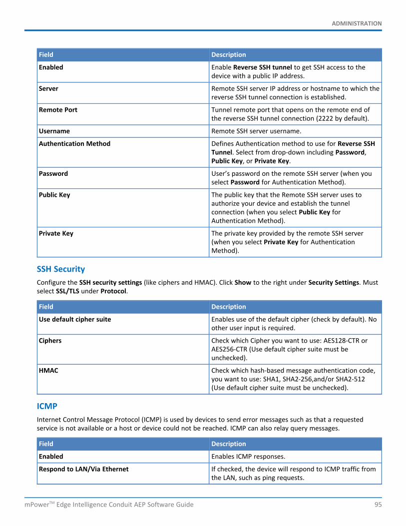
ADMINISTRATION
mPowerTM Edge Intelligence Conduit AEP Software Guide 95
Field Description
Enabled Enable Reverse SSH tunnel to get SSH access to thedevice with a public IP address.
Server Remote SSH server IP address or hostname to which thereverse SSH tunnel connection is established.
Remote Port Tunnel remote port that opens on the remote end ofthe reverse SSH tunnel connection (2222 by default).
Username Remote SSH server username.
Authentication Method Defines Authentication method to use for Reverse SSHTunnel. Select from drop-down including Password,Public Key, or Private Key.
Password User’s password on the remote SSH server (when youselect Password for Authentication Method).
Public Key The public key that the Remote SSH server uses toauthorize your device and establish the tunnelconnection (when you select Public Key forAuthentication Method).
Private Key The private key provided by the remote SSH server(when you select Private Key for AuthenticationMethod).
SSH SecurityConfigure the SSH security settings (like ciphers and HMAC). Click Show to the right under Security Settings. Mustselect SSL/TLS under Protocol.
Field Description
Use default cipher suite Enables use of the default cipher (check by default). Noother user input is required.
Ciphers Check which Cipher you want to use: AES128-CTR orAES256-CTR (Use default cipher suite must beunchecked).
HMAC Check which hash-based message authentication code,you want to use: SHA1, SHA2-256,and/or SHA2-512(Use default cipher suite must be unchecked).
ICMPInternet Control Message Protocol (ICMP) is used by devices to send error messages such as that a requestedservice is not available or a host or device could not be reached. ICMP can also relay query messages.
Field Description
Enabled Enables ICMP responses.
Respond to LAN/Via Ethernet If checked, the device will respond to ICMP traffic fromthe LAN, such as ping requests.
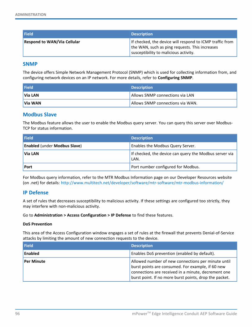
ADMINISTRATION
96 mPowerTM Edge Intelligence Conduit AEP Software Guide
Field Description
Respond to WAN/Via Cellular If checked, the device will respond to ICMP traffic fromthe WAN, such as ping requests. This increasessusceptibility to malicious activity.
SNMPThe device offers Simple Network Management Protocol (SNMP) which is used for collecting information from, andconfiguring network devices on an IP network. For more details, refer to Configuring SNMP.
Field Description
Via LAN Allows SNMP connections via LAN
Via WAN Allows SNMP connections via WAN.
Modbus SlaveThe Modbus feature allows the user to enable the Modbus query server. You can query this server over Modbus-TCP for status information.
Field Description
Enabled (under Modbus Slave) Enables the Modbus Query Server.
Via LAN If checked, the device can query the Modbus server viaLAN.
Port Port number configured for Modbus.
For Modbus query information, refer to the MTR Modbus Information page on our Developer Resources website(on .net) for details: http://www.multitech.net/developer/software/mtr-software/mtr-modbus-information/
IP DefenseA set of rules that decreases susceptibility to malicious activity. If these settings are configured too strictly, theymay interfere with non-malicious activity.
Go to Administration > Access Configuration > IP Defense to find these features.
DoS Prevention
This area of the Access Configuration window engages a set of rules at the firewall that prevents Denial-of-Serviceattacks by limiting the amount of new connection requests to the device.
Field Description
Enabled Enables DoS prevention (enabled by default).
Per Minute Allowed number of new connections per minute untilburst points are consumed. For example, if 60 newconnections are received in a minute, decrement oneburst point. If no more burst points, drop the packet.
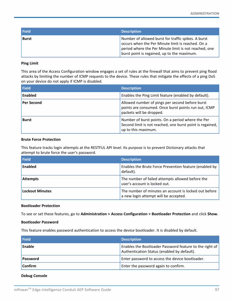
ADMINISTRATION
mPowerTM Edge Intelligence Conduit AEP Software Guide 97
Field Description
Burst Number of allowed burst for traffic spikes. A burstoccurs when the Per Minute limit is reached. On aperiod where the Per Minute limit is not reached, oneburst point is regained, up to the maximum.
Ping Limit
This area of the Access Configuration window engages a set of rules at the firewall that aims to prevent ping floodattacks by limiting the number of ICMP requests to the device. These rules that mitigate the effects of a ping DoSon your device do not apply if ICMP is disabled.
Field Description
Enabled Enables the Ping Limit feature (enabled by default).
Per Second Allowed number of pings per second before burstpoints are consumed. Once burst points run out, ICMPpackets will be dropped.
Burst Number of burst points. On a period where the PerSecond limit is not reached, one burst point is regained,up to this maximum.
Brute Force Protection
This feature tracks login attempts at the RESTFUL API level. Its purpose is to prevent Dictionary attacks thatattempt to brute force the user's password.
Field Description
Enabled Enables the Brute Force Prevention feature (enabled bydefault).
Attempts The number of failed attempts allowed before theuser's account is locked out.
Lockout Minutes The number of minutes an account is locked out beforea new login attempt will be accepted.
Bootloader Protection
To see or set these features, go to Administration > Access Configuration > Bootloader Protection and click Show.
Bootloader Password
This feature enables password authentication to access the device bootloader. It is disabled by default.
Field Description
Enable Enables the Bootloader Password feature to the right ofAuthentication Status (enabled by default).
Password Enter password to access the device bootloader.
Confirm Enter the password again to confirm.
Debug Console
ADMINISTRATION
98 mPowerTM Edge Intelligence Conduit AEP Software Guide
This feature allows the customer to run Silent Mode which turns off the output to the Debug Console. The consoleoutput is enabled by default (i.e. Silent Mode is disabled).
When Silent Mode is enabled, Debug Console is turned off. (NOTE: During boot, the device does not output anyinformation after the notice that the Linux Kernel is being decompressed including no login prompt, etc.)
Field Description
Enable Enables Silent Mode which turns off output to theDebug Console (disabled by default meaning DebugConsole output is on).
After making all your desired changes, click Submit, then click Save and Restart.
RADIUS ConfigurationThe RADIUS protocol supports authentication, user session accounting, and authorization of users to the device.This authentication, accounting, and authorization is independent of the local users created on the device. Theuser can enable Authentication, Accounting, or both options.
RADIUS user details:
Access to device if role is one of those in the provided list (Administrator, Engineer, or Monitor).All RADIUS users do not have SSH access to the device.RADIUS creates a temporary session instead of a local account like local users.RADIUS uses shared key encryption.Local users shall take priority over RADIUS user (if a RADIUS user has the same username as a local user, theRADIUS user cannot log in even if the local user is disabled).RADIUS user with Administrator role can view and modify all local users (but cannot delete a localAdministrator if it is the only local admin user on the device).RADIUS users with Engineer and Monitor role cannot view or modify user details. They do not have accessto the User Accounts page.RADIUS users cannot change their own password in the Web UI.
To set up the RADIUS server configuration:
1. Go to Administration > RADIUS Configuration.2. To enable authentication, check Enable Authentication.3. To enable accounting, check Enable Accounting.4. Enter the following fields for RADIUS configuration:
a. Primary Serverb. Authentication Port (for Primary Server)c. Accounting Port (for Primary Server)d. Secondary Servere. Authentication Port (for Secondary Server)f. Accounting Port (for Secondary Server)
5. Under Options, enter the following fields:

ADMINISTRATION
mPowerTM Edge Intelligence Conduit AEP Software Guide 99
a. Shared Secret Key value is used to: 1) encrypt packets between the RADIUS Server and device, 2)encrypt RADIUS attributes such as user password, and 3) verify that RADIUS messages have not beenmodified in transit. This value must be equal to the shared secret that is set up in RADIUS server. TheShared Secret Key can be up to 128 characters long. You can click the eye icon to hide the key.
b. Authentication Protocol: select from drop-down list including PAP, EAP-PEAPv0/MSCHAPv2, or EAP-TTLS/PAPv0
c. Timeout is the interval in seconds between tries to connect to RADIUS server in case ofcommunication failure. Maximum is 10 seconds.
d. Retries is the number of tries to connect to RADIUS server in case of communication failure.
6. Advanced Options are used when Authentication Protocol is EAP-PEAPv0/MSCHAPv2 or EAP-TTLS/PAPv0.If Protocol is PAP, these settings are ignored:
a. Check Use Anonymous ID if you want to enable identity privacy. The device does not send itsidentity in plain text before the device has authenticated the RADIUS server.
b. Anonymous ID is a name or value that the device will use in the identity response when “UseAnonymous ID” is enabled.
c. Check Check Server Certificate Hostname to allow the server certificate CN (common name) to bevalidated by the device.
7. Click Submit.8. To save your changes, click Save and Restart
Generating a New CertificateBecause the device uses a self-signed website certificate, your browser shows a certificate error or warning. Ignorethe warning and add an exception or add your device address to the trusted sites.
To generate a new certificate:
1. Go to Administration > X.509 Certificate. The X.509 Certificate window displays the details of thecertificate that is currently used.
2. Click Generate to open the Generate Certificate window.3. In the Common Name field, enter the name, hostname, or IP address, depending on what you use to
connect to the device. The web browser uses this field to check for a valid certificate.4. In the Days field, enter the amount of days before the certificate will expire.5. In the Country field, enter the 2-letter code for the country name.6. In the State/Province field, enter the state or province for which the certificate is valid.7. In the Locality/City field, enter the locality or the city for which the certificate is valid.8. In the Organization field, enter the organization name for which the certificate is valid.9. In the Email Address field, enter the email address of the person responsible for the device. Typically this
is the administrator. This field may be left blank.10. Click Generate. Wait until the certificate is generated. You may have to reboot to complete the
operation.11. If you are finished making changes, click Save and Restart.
Importing a CertificateTo import a certificate (in .pem format):
ADMINISTRATION
100 mPowerTM Edge Intelligence Conduit AEP Software Guide
1. Go to Administration > X.509 Certificate. The Certificate window displays the details of the certificatethat is currently used.
NOTE: A certificate with a key size greater than 2048 bits causes a delay accessing the Web UI after thedevice starts. A certificate with a key size less than 2048 bits is not recommended since it is less secure andmay become breakable in the near future.
2. Click Import to open Upload Certificate window.3. Click Browse to select a valid certificate to be uploaded. Check that your certificate file format is .pem.4. Click Upload. Wait until the file is uploaded.5. To save your changes, click Save and Restart.
NOTE: Your certificate file must be in .pem format.
Uploading CA CertificateThis page allows a user to upload an X.509 CA (Certifying Authority) Certificate.
To upload a CA certificate:
1. Go to Administration > X.509 CA Certificates.2. Click Choose File and browse for your CA certificate file.3. Click Open.4. Once your file is selected, click Import.5. Your CA certificate file displays in the certificate list along with relevant details.6. You may delete or remove a certificate by clicking the trash can icon to the right under Options.
Note: Both add and remove functions may take up to two minutes to update. Once updated, the changes areapplied immediately. There is no need to restart the device after CA certificate is added or removed. For bi-directional certificate authentication or client authentication, go to Device Administration > Access Configuration> HTTPS Security > Authentication and check Client Authentication. See HTTPS Security on theAccessConfiguration page for more details.
Setting up the Remote ManagementTo modify DeviceHQ automatic update settings, go to options under Auto-Update Settings and refer to ManagingYour Device Remotely.
1. Go to Administration > Remote Management > Remote Server. To allow the device to connect to theRemote Management Server, check Enabled.
2. If you want the device to use a secure connection, check SSL Enabled.3. The Server Name field is pre-populated with the address of the Remote Management Server.4. The Server Port field is pre-populated with the port the Remote Management Server listens on. You likely
do not need to change this.5. In the Account Key field, type the account key received from the Remote Management administrator.
The device is not allowed to connect to the Remote Management Server without a valid account key.6. Click Submit.7. To save your changes, click Save and Restart.
ADMINISTRATION
mPowerTM Edge Intelligence Conduit AEP Software Guide 101
Managing Your Device RemotelyDeviceHQ™ can monitor devices, reboot devices, and perform remote software and configuration updates.
NOTE: Reboot the device before performing any firmware updates.
To configure your device to use DeviceHQ:
1. Go to Administration > Remote Management and check Enabled.2. Go to options under DeviceHQ Check-In Settings.3. Enable the Intervals check box to check in to DeviceHQ periodically at the specified interval.*If you do not
select Intervals, certain DeviceHQ features will NOT be available. See note below for details.
a. To define how often the device connects to DeviceHQ to check in and request any pending updates,set the Check-In Interval field to the desired number of minutes between 240-10080 (240 minutesto 1 week). Note: Your device must connect to DeviceHQ every 4 hours at a minimum. If you set thecheck-in interval to less than 4 hours, your change is ignored.
b. To define how often the device connects to DeviceHQ to send GPS data, set the GPS Data Intervalfield to the desired number of minutes, between 240-10080 (240 minutes to 1 week). Note: SomeMTR models do not have GPS. Then this field does not display.
4. Enable Single Check-In to configure your device to check-in to DeviceHQ at the specific date and time. Ifyou enable Single Check-In, click the Date field to select the date from the calendar picker, and thenenter the Time (HH:MM) for your device to check-in.
5. Enable Repeatable to check-in to DeviceHQ periodically at the specified time daily or at the specific daysof the week.
a. Select Daily from the Repeat drop-down to check in to DeviceHQ every day, and enter the Time(HH:MM) for your device to check-in.
b. Select Custom from the Repeat drop-down, then specify the days of the week, and enter the Time(HH:MM) for your device to check-in.
6. Go to options under Update Settings7. If Sync with Dial-On-Demand is checked and cellular dial-on-demand is enabled, the connection is not
dialed solely for the purpose of connecting to DeviceHQ. The device will connect to DeviceHQ only whenother traffic brings up the link.
8. Check Allow Firmware Upgrade if you want DeviceHQ to make automatic updates of your firmware.9. Check Allow Configuration Upgrade if you want DeviceHQ to make automatic updates of your
configuration software.10. Check Allow Radio Firmware Upgrade if you want DeviceHQ to make automatic updates of your cellular
radio firmware.11. Click Submit.12. Click Save and Restart to save your changes.
*NOTE: If you do not select Intervals, certain DeviceHQ features will NOT be available including:missed check-in alertsdevice rebooted alertsautomatically scheduled device log uploadshome page notices for rebooted or missed check-in devices
ADMINISTRATION
102 mPowerTM Edge Intelligence Conduit AEP Software Guide
NotificationsThe device can send alerts via email, SMS, and/or SNMP. To use these options, enable SMTP (see SMTP Settings fordetails), SMS (see Configuring SMS for details), and SNMP Traps (see Configuring SNMP for details).
A time stamp is added to the actual notifications. The format is YYYY-MM-DD HH:MM.
To setup notifications:
1. Go to Administration > Notifications > Configuration.2. Under Recipient Group, click Add Group (you must add a group before you can edit/save your alert).3. In the Create Recipient Group window, enter your Group Name.4. Click Add Phone. Enter the person's Name and Phone Number. Then click Finish.5. Click Add Email. Enter the person's Name and Email. Then click Finish.6. Add name, phone number and email for each person in your group. When done, click Submit.7. See the list of available alerts:
High Data UsageLow Signal StrengthDevice RebootsEthernet Interface FailureCellular Interface FailureEthernet Data TrafficCellular Data TrafficWAN Interface FailoverPing FailureSecurity ViolationResource OveruseWi-Fi Interface Failure*Wi-Fi Data Traffic*
*Only available on models with Wi-Fi capabilities8. Click on the pencil icon under the Edit column for the alert you want to use and configure. The Edit dialog
box appears for your chosen alert.
For High Data Usage:
1. Check Enabled.2. Under Data Plan Details, select the Plan Type from the drop down menu which includes Monthly or
Custom Interval.3. If you choose Custom Interval, enter the Interval length in days.4. Select the Start Date from the calendar picker.5. Enter the Limit in MB for data usage.6. In Notify At, enter the percentage of the limit that triggers notification to be sent.7. Select alert recipients from Recipient Group.8. Select how you want to send alerts by clicking Email, SMS, or SNMP.9. Click Finish.

ADMINISTRATION
mPowerTM Edge Intelligence Conduit AEP Software Guide 103
10. To save your changes, click Save and Restart.
For Low Signal Strength:
1. Check Enabled.2. Enter the Signal Threshold in dBm.3. Enter the Duration in seconds.4. Under Alerts, select the recipients under Recipient Group.5. In Notify, enter the frequency of notification (in hours). Default is 24.6. Select how you want to send alerts by clicking Email, SMS, or SNMP.7. Click Finish.8. To save your changes, click Save and Restart.
For Device Reboots:
1. Check Enabled.2. Under Alerts, select the recipients under Recipient Group.3. In Notify, the field for frequency of notification is shown. The predefined value is Always and cannot be
modified by the user.4. Select how you want to send alerts by clicking Email, SMS, or SNMP.5. Click Finish.6. To save your changes, click Save and Restart.
For Ethernet Interface Failure:
1. Check Enabled.2. Enter the Duration in seconds.3. Under Notification Options, select the recipients from the drop-down in Recipient Group.4. In Notify, enter the frequency of notification (in hours). Default is 24.5. Select how you want to send alerts by clicking Email, SMS or SNMP.6. Click Finish.7. To save your changes, click Save and Restart.
For Cellular Interface Failure:
1. Check Enabled.2. Enter the Duration in seconds.3. Under Notification Options, select the recipients from the drop-down in Recipient Group.4. In Notify, enter the frequency of notification (in hours). Default is 24.5. Select how you want to send alerts by clicking Email, SMS or SNMP.6. Click Finish.7. To save your changes, click Save and Restart.
For Ethernet Data Traffic:
1. Check Enabled.2. Enter Interval in hours when alert is sent.3. Under Notification Options, select the recipients from the drop-down in Recipient Group.

ADMINISTRATION
104 mPowerTM Edge Intelligence Conduit AEP Software Guide
4. In Notify, the constant value is Always.5. Select how you want to send alerts by clicking Email, SMS or both.6. Click Finish.7. To save your changes, click Save and Restart.
For Cellular Data Traffic:
1. Check Enabled.2. Enter Interval in hours when alert is sent.3. Under Notification Options, select the recipients from the drop-down in Recipient Group.4. In Notify, the constant value is Always.5. Select how you want to send alerts by clicking Email, SMS or both.6. Click Finish.7. To save your changes, click Save and Restart.
For WAN Interface Failover:
1. Check Enabled.2. Enter the Timeout in seconds.3. Select what to Notify On from the drop-down.4. Under Notification Options, select the recipients from the drop-down in Recipient Group.5. In Notify, the constant value is Always.6. Select how you want to send alerts by clicking Email, SMS or SNMP.7. Click Finish.8. To save your changes, click Save and Restart.
For Ping Failure:
1. Check Enabled.2. Under Ping Details, select the Network Interface from the drop-down.3. Enter the IP Address or URL that you want to ping.4. Enter the Count.5. Enter the Failure Threshold.6. Enter the Ping Interval.7. Under Notification Options, select the recipients from the drop-down in Recipient Group.8. In Notify, the constant value is Always.9. Select how you want to send alerts by clicking Email, SMS or SNMP.10. Click Finish.11. To save your changes, click Save and Restart.
For Security Violation:
1. Check Enabled.2. Under Notification Options, select the recipients from the drop-down in Recipient Group.3. In Notify, the constant value is Always.4. Select how you want to send alerts by clicking Email, SMS , or SNMP.
ADMINISTRATION
mPowerTM Edge Intelligence Conduit AEP Software Guide 105
5. Click OK.
For Resource Overuse:
1. Check Enabled.2. Under Notification Options, select the recipients from the drop-down in Recipient Group.3. In Notify, the constant value is Always.4. Select how you want to send alerts by clicking Email, SMS , or SNMP.5. Click OK.
The following notifications are only available on models with Wi-Fi capabilities:
For Wi-Fi Interface Failure:
1. Check Enabled.2. Enter the Duration in seconds.3. Under Notification Options, select the recipients from the drop-down in Recipient Group.4. In Notify, enter the frequency of notification (in hours). Default is 24.5. Select how you want to send alerts by clicking Email, SMS or SNMP.6. Click Finish.7. To save your changes, click Save and Restart.
For Wi-Fi Data Traffic:
1. Check Enabled.2. Enter Interval in hours when alert is sent.3. Under Notification Options, select the recipients from the drop-down in Recipient Group.4. In Notify, the constant value is Always.5. Select how you want to send alerts by clicking Email or SMS.6. Click Finish.7. To save your changes, click Save and Restart.
Customizing the User InterfaceYou can change how the user interface on your device appears. To change the interface:
1. From the Navigation pane, select Administration > Web UI Customization.2. To define what information appears on the Administration: Support page, use the Support group. See
Customizing Support Information.3. To define other settings, use the Device Settings group. See Specifying Device Settings.
Customizing Support InformationTo customize the interface displaying information that can be used to support users:
1. To enable display of the custom support information, go to Administration > Web UI Customization >Support Information and check Show Custom Info.
2. Type the desired information into the optional fields including:
Company Name

ADMINISTRATION
106 mPowerTM Edge Intelligence Conduit AEP Software Guide
CountryFaxAddress 1Address 2CityState/ PrvZip CodeCity
3. To add a phone number:
a. Click Add Phone.b. A label can appear next to the phone number, for example Fax or Phone or International. In the
Label field, enter text that describes the phone number.c. In the Number field, type the phone number.
4. To add a link to a website, click Add Link.
a. To label the website, type label text in Label field.b. In the URL field, type the website's link.c. To add further descriptive text about the site, type the information in the Text field.
5. To add an image, click Upload Image:
a. Click Browse, go to the location of the image, and select the image.b. Click OK.
6. To delete an existing image, click Remove Image.7. Click Submit.8. To save your changes, click Save and Restart.
Specifying Device SettingsTo define other custom settings for devices:
1. Go to Administration > Web UI Customization > Device Settings.2. Enter desired information in the optional fields including:
Device NameCustom IDButton ColorButton Font ColorHighlight ColorHighlight Font Color
Note: To define color fields, use #rrggbb format.3. To add a favorite icon, also known as a shortcut icon or bookmark icon, in the Custom Favicon field, click
Browse to find where the Favicon file resides, select the desired file, and click Upload Icon.4. To remove an existing favorite icon, click Remove Icon.
ADMINISTRATION
mPowerTM Edge Intelligence Conduit AEP Software Guide 107
5. To add a custom logo, next to the Custom Logo field, click Browse to find where the logo file resides,select the desired file, and click Upload Logo.
6. To remove an existing logo, click Remove Logo.7. Click Submit.8. To save your changes, click Save and Restart.
Upgrading FirmwareBefore upgrading: reboot the device.
Upgrade the device's firmware to the latest version. You can download firmware upgrades from the MultiTechwebsite or update your firmware automatically through MultiTech's DeviceHQ™ system.
For added security, Signed Firmware Validation is automatically used once it's enabled after upgrading fromversion 5.1 and higher. This authentication method prevents attempts to load invalid or damaged firmware files inorder to defeat possible tampering. The module does not load any firmware that MultiTech did not digitally sign.
First, check your firmware version. Refer to the top of your configuration software window. To upgrade thefirmware on your device:
1. Before you upgrade your firmware, save your present configuration as a backup. Otherwise, seeDeviceHQ.
2. Go to the MultiTech website, locate the firmware upgrade file you want for your device, and downloadthis file to a known location.
3. Select Administration > Firmware Upgrade. The Administration: Firmware Upgrade pane opens.4. Click the Choose Firmware Upgrade File button:
a. Click Browse to find where the firmware file resides that you want to apply.b. Select the file and click Open. The file name appears next to the Choose Firmware Upgrade File
button. Make sure you select the correct BIN file; otherwise, your device can become inoperable.
5. Click Start Upgrade.6. A message about time needed to upgrade appears. Click OK. A progress bar appears indicating the status
of the upgrade. When upgrade is completed, your device reboots.7. After the firmware upgrade is complete, verify your configuration to make sure it is what you expected.
Note:The new firmware is written into flash memory.It may take up to 10 minutes to upgrade the firmware. Do not interfere with the devices's power orpress the reset button during this time.The DeviceHQ is a cloud platform that provides the ability to remotely manage and upgrade devices.Please see the Remote Management section or visit www.devicehq.com for more information.
Saving and Restoring SettingsTo restore previous configuration settings to your device, to restore settings to their factory defaults, or to savethe current configuration:
1. Go to Administration > Save/Restore > Save and Restore Configuration.2. To restore a configuration from a previously saved file, go to Restore Configuration From File:
ADMINISTRATION
108 mPowerTM Edge Intelligence Conduit AEP Software Guide
a. Next to the Restore Configuration field, click Browse.b. Navigate to the location where the configuration file is stored and select the desired file.c. Click Restore. The device reboots.
3. To save your current configuration to a file, go to Save Configuration To File:
a. Click Save.b. Navigate to the location where you wish to save the file and select location.
4. This option is only available if you had reset to user-defined configuration. (Also, holding the reset buttonon the device for 30 seconds overrides user-defined settings and resets to factory default.) To reset thedevice's configuration to the factory settings, go to Reset to Factory Default Configuration:
a. Click Reset.b. A dialog box appears prompting you to confirm that you want to restore to factory default settings.c. Click OK.
5. This option is only available if you set user-defined settings first. (Also, holding the reset button on thedevice for 5 seconds sets user-defined defaults) To restore the device's configuration to the user-definedconfiguration settings, go to Reset to User-Defined Configuration:
a. Click Restore.b. A dialog box appears prompting you to confirm that you want to restore to a set of user-defined
settings.c. Click OK.
6. To set deployment-specific default settings, click Set Current Configuration As User-Defined Default.
a. A dialog box appears prompting you to confirm that you want to restore to a set of user-definedsettings.
b. Click OK.
7. To save a current configuration:
a. Click Save.b. A dialog box appears asking you if you want to open or save the configuration file. Click Save.c. Navigate to the location where you want to store the configuration. Click Save.d. A progress dialog box appears to indicate that the configuration is being saved. Click Close.
Using the Debugging OptionsThe device has utilities to help troubleshoot and solve technical problems. You can set up your device:
To automatically reboot itself at a particular time of day or use a particular offset in hours from boot.To record and report Syslog messages that can help you resolve potential issues with your device.
You can also communicate directly with the device's cellular radio. To do this:
1. From Administration, select Debug Options.2. Click the down arrow to the far right of the Radio Terminal screen to view the terminal window.3. Enter AT commands to the radio.
ADMINISTRATION
mPowerTM Edge Intelligence Conduit AEP Software Guide 109
See other topics for additional Debug Options:
Auto Reboot Timer (automatically reboot device)Remote Syslog (configuring syslog)Ping and Reset OptionsStatistics Settings
See also: Statistics Configuration Fields
Automatically rebooting the deviceTo choose a specific time to reboot daily, the amount of time that passes before the device automatically rebootsitself, or to disable this function:
1. Go Administration > Debug Options > Auto Reboot Timer, select DAILY, TIMER, or DISABLED from thedrop-down under Auto Reboot.
2. If you chose DAILY, enter the Time of day you want device to reboot (in HH:MM format).3. If you chose TIMER, enter the Interval (in hours) for the amount of time that passes before the device
automatically reboots itself.4. If you do NOT want the device to automatically reboot, select DISABLED (default).
Configuring Remote SyslogTo enable and configure Remote Syslog to capture and send log data from your device, you must have local syslogsoftware installed.
To set up a log request in DeviceHQ, under Devices, select your device. Then click on Tasks and select RequestDevice Logs. After the request has been completed, return to the device administration software.
1. To activate Remote Syslog, go to Administration > Debug Options > Remote Syslog, check Enabled.2. To enable a remote server to receive and store the device's log data, under Remote Syslog, in the IP
Address field, type the IP address of the desired server.3. To determine the amount of log information that is collected, under Logging, in the Debug Log Level,
select the type of information from the values in the dropdown menu which includes: Minimum, Error,Warning, Info, Debug, and Maximum. The system will collect the type of information you specify. Forexample, Maximum will collect all the log data available while Warning will collect anything that is awarning or above that level.
4. To download syslog information directly from the device, click Download Logs.5. Click Submit.6. To save your changes, click Save and Restart.
Statistics SettingsTo configure Statistics:
1. Go to Administration > Debug Options > Statistics.2. Enter the Save Timeout in seconds.3. Enter the Save Data Limit in megabytes.4. Click Submit.5. To save your settings, click Save and Restart.
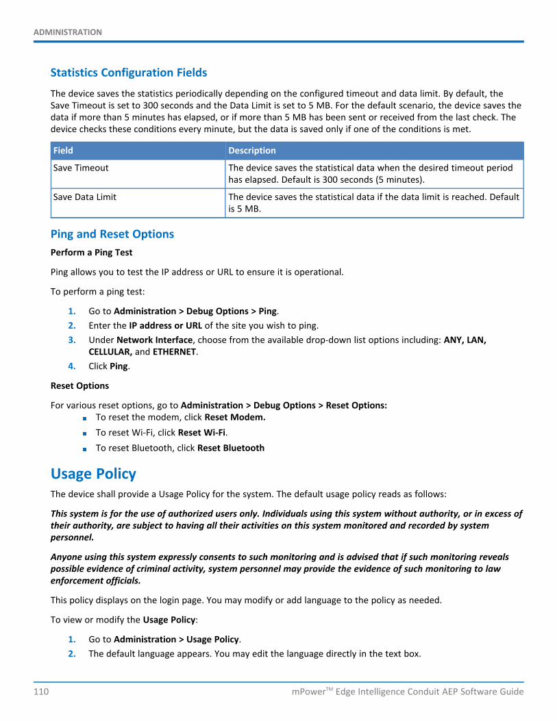
ADMINISTRATION
110 mPowerTM Edge Intelligence Conduit AEP Software Guide
Statistics Configuration Fields
The device saves the statistics periodically depending on the configured timeout and data limit. By default, theSave Timeout is set to 300 seconds and the Data Limit is set to 5 MB. For the default scenario, the device saves thedata if more than 5 minutes has elapsed, or if more than 5 MB has been sent or received from the last check. Thedevice checks these conditions every minute, but the data is saved only if one of the conditions is met.
Field Description
Save Timeout The device saves the statistical data when the desired timeout periodhas elapsed. Default is 300 seconds (5 minutes).
Save Data Limit The device saves the statistical data if the data limit is reached. Defaultis 5 MB.
Ping and Reset OptionsPerform a Ping Test
Ping allows you to test the IP address or URL to ensure it is operational.
To perform a ping test:
1. Go to Administration > Debug Options > Ping.2. Enter the IP address or URL of the site you wish to ping.3. Under Network Interface, choose from the available drop-down list options including: ANY, LAN,
CELLULAR, and ETHERNET.4. Click Ping.
Reset Options
For various reset options, go to Administration > Debug Options > Reset Options:To reset the modem, click Reset Modem.To reset Wi-Fi, click Reset Wi-Fi.To reset Bluetooth, click Reset Bluetooth
Usage PolicyThe device shall provide a Usage Policy for the system. The default usage policy reads as follows:
This system is for the use of authorized users only. Individuals using this system without authority, or in excess oftheir authority, are subject to having all their activities on this system monitored and recorded by systempersonnel.
Anyone using this system expressly consents to such monitoring and is advised that if such monitoring revealspossible evidence of criminal activity, system personnel may provide the evidence of such monitoring to lawenforcement officials.
This policy displays on the login page. You may modify or add language to the policy as needed.
To view or modify the Usage Policy:
1. Go to Administration > Usage Policy.2. The default language appears. You may edit the language directly in the text box.

ADMINISTRATION
mPowerTM Edge Intelligence Conduit AEP Software Guide 111
3. When completed, click Submit.4. To save your changes, click Save and Restart.
If at any time you want to return the device to the default setting, click the Reset to Default button in the bottomright corner. (This reverts the Usage Policy back to the default language.)
STATUS & LOGS
112 mPowerTM Edge Intelligence Conduit AEP Software Guide
Chapter 12 – Status & LogsViewing Device StatisticsThe device collects sent/received traffic data for WAN, Cellular, and Ethernet networks. The daily statistical data isstored on the device for a 365-day period. All data that is older than 365 days is automatically deleted.
1. From Status & Logs on the left side of the Web Management interface, select Statistics.2. The application categorizes statistics about your device. To see statistics that appear in a particular
category, click the appropriate tab.SystemEthernetWi-FiAccess PointCellularSerialBluetoothGREIPSecOpenVPNLoRa
Definitions
A data usage bar chart and a cumulative usage line chart are available for Ethernet, Wi-Fi, and Cellular. The DataUsage bar chart also shows statistics for data sent and data received. The following list includes some definitions tohelp you understand some of the data. Not all of the available statistics are listed here or shown in every tab.
Total: Total number of sent/received bytes for a 365-day period.Today: Total number of sent/received bytes for today.Sessions: Bytes.Packets: Number of successfully transmitted (TX) and received (RX) packets.Errors: Number of errors that occurred. Possibly due to connection issues or network congestion.Dropped: Number of dropped packets. Possibly due to memory constraints.Overruns: Number of overruns that occurred. Possibly due to processing constraints.Frame: Number of invalid packets.Carrier: Number of signal modulation errors that occurred (possibly due to physical connection).Collisions: Number of packet collisions that occurred due to network congestion.Queue Length: Length of the transmit queue.MTU (Maximum Transmission Unit): the maximum size of packet content (Bluetooth only).ACL (Asynchronous Connection-Less): the typical protocol used for data packets (Bluetooth only).SCO (Synchronous Connection-Oriented): the typical protocol used for voice (Bluetooth only).Events: Number of events that occurred on a Bluetooth connection (Bluetooth only).Commands: Number of commands given to devices on a Bluetooth connection (Bluetooth only).
STATUS & LOGS
mPowerTM Edge Intelligence Conduit AEP Software Guide 113
Cumulative and Daily Usage
Click Show Cumulative Usage or Show Daily Usage to display the desired view. Default chart view is Daily Usagefor 30-day period.
Timeframe of Chart
Change the time frame for the chart by clicking Start Date or End Date using calendar to set a different date.
Show Log
The associated run-time logs for this section.
LoRa Statistics
The LoRa statistics tab contains Received and Sent statistics for LoRa packets received and sent by the LoRanetwork server. These statistics can be cleared with the Clear History button. This tab also contains the list ofnodes that have joined the network the device is supporting. There are statistics for each node and also statusinformation in this table. This list can be refreshed by clicking on the Refresh Node List button.
Service StatisticsOn the Web Management interface side menu, click Status & Logs > Services to display the Service Statisticswindow. This window shows the configuration (enabled or disabled) and the status of the following services:
DDNSSNTPCellular RTCTCP/ICMP Keep AliveDial-on-DemandSMTPSMSFailover
Mail LogMail Log shows the recent email delivery attempts and the mail log details. Mail log entries are sorted by date withthe most recent on top. You can select the number of emails to display in the queue. Possible values are 5, 10, 25,50, or All emails.
1. Go to Status & Logs > Mail Log to display the Mail Log window.2. To see the delivery details, click the eye icon under Options for the desired email entry.3. To delete all mail log entries, click Purge Log.
Note: Logs do not persist through power cycles.
Mail QueueMail Queue shows the emails that are waiting to be sent. The most recent email delivery attempts are on top. Youcan select the number of emails to display in the queue. Possible values are 5, 10, 25, 50, and All emails. Note:Logs do not persist through power cycles.
STATUS & LOGS
114 mPowerTM Edge Intelligence Conduit AEP Software Guide
1. Go to Status & Logs > Mail Queue to display the Mail Queue window.2. To view the delivery details for an individual email, click the eye icon under Options for the desired
email entry.
Notifications SentThis page displays attempts to send Notifications via email, SMS, or SNMP.
The list includes the following details of each attempted notification: Date, Message, Recipient Group, and thestatus of the notification under each communication method including Email, SMS, and SNMP. A check indicatessuccess via that method. An X means failure. No symbol or a blank space indicates that method was notattempted.
To view Notifications Sent:
1. Go to Status & Logs > Notifications Sent.2. In the upper right corner, click Refresh to update the list.3. To the right of Refresh, click Delete All Notifications if you want to remove all items in the list.
RF SurveyRF survey is not available for LTE models.
If you have a non-LTE device with a SIM card and want to perform an RF Survey, enter this address:192.168.2.1/rf_survey and follow the instructions below. (The link uses the default IP address for the device uponlog in. If you change the IP address of the device, make sure to use that new IP address in the link).
After the RF Survey, you must reset the device in order to restore cellular radio functionality.
The RF Survey tool allows you to view the list of the cell towers that belong to the carrier and their signal qualitydetails such as Signal Level and Signal Noise Ratio. You need a SIM card to acquire the list of available cell towers.
Note: Selecting this tool terminates any existing PPP connection
1. Enter this address: 192.168.2.1/rf_survey to open the RF Survey page.The search for the cell towers takes up to 2 minutes. The wait icon displays while the search isin progress.The cell tower to which the device is currently connected displays at the top of the list.
2. To view the Signal Strength chart of a carrier, under Options, click the eye icon for the carrier.The Carrier Details window appears.This feature helps you decide which area has better signal strength and thus a better locationfor the device.
3. After the RF survey, reset your device. Go to Commands > Restart Device.
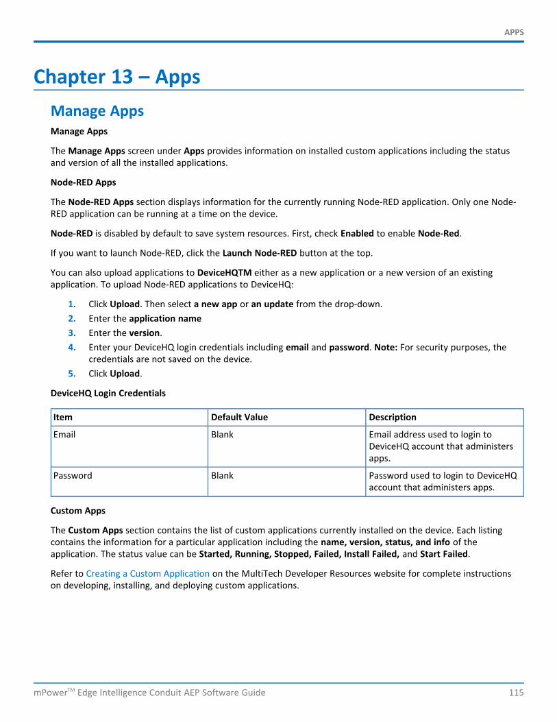
APPS
mPowerTM Edge Intelligence Conduit AEP Software Guide 115
Chapter 13 – AppsManage AppsManage Apps
The Manage Apps screen under Apps provides information on installed custom applications including the statusand version of all the installed applications.
Node-RED Apps
The Node-RED Apps section displays information for the currently running Node-RED application. Only one Node-RED application can be running at a time on the device.
Node-RED is disabled by default to save system resources. First, check Enabled to enable Node-Red.
If you want to launch Node-RED, click the Launch Node-RED button at the top.
You can also upload applications to DeviceHQTM either as a new application or a new version of an existingapplication. To upload Node-RED applications to DeviceHQ:
1. Click Upload. Then select a new app or an update from the drop-down.2. Enter the application name3. Enter the version.4. Enter your DeviceHQ login credentials including email and password. Note: For security purposes, the
credentials are not saved on the device.5. Click Upload.
DeviceHQ Login Credentials
Item Default Value Description
Email Blank Email address used to login toDeviceHQ account that administersapps.
Password Blank Password used to login to DeviceHQaccount that administers apps.
Custom Apps
The Custom Apps section contains the list of custom applications currently installed on the device. Each listingcontains the information for a particular application including the name, version, status, and info of theapplication. The status value can be Started, Running, Stopped, Failed, Install Failed, and Start Failed.
Refer to Creating a Custom Application on the MultiTech Developer Resources website for complete instructionson developing, installing, and deploying custom applications.