Embed Size (px)
Citation preview
1
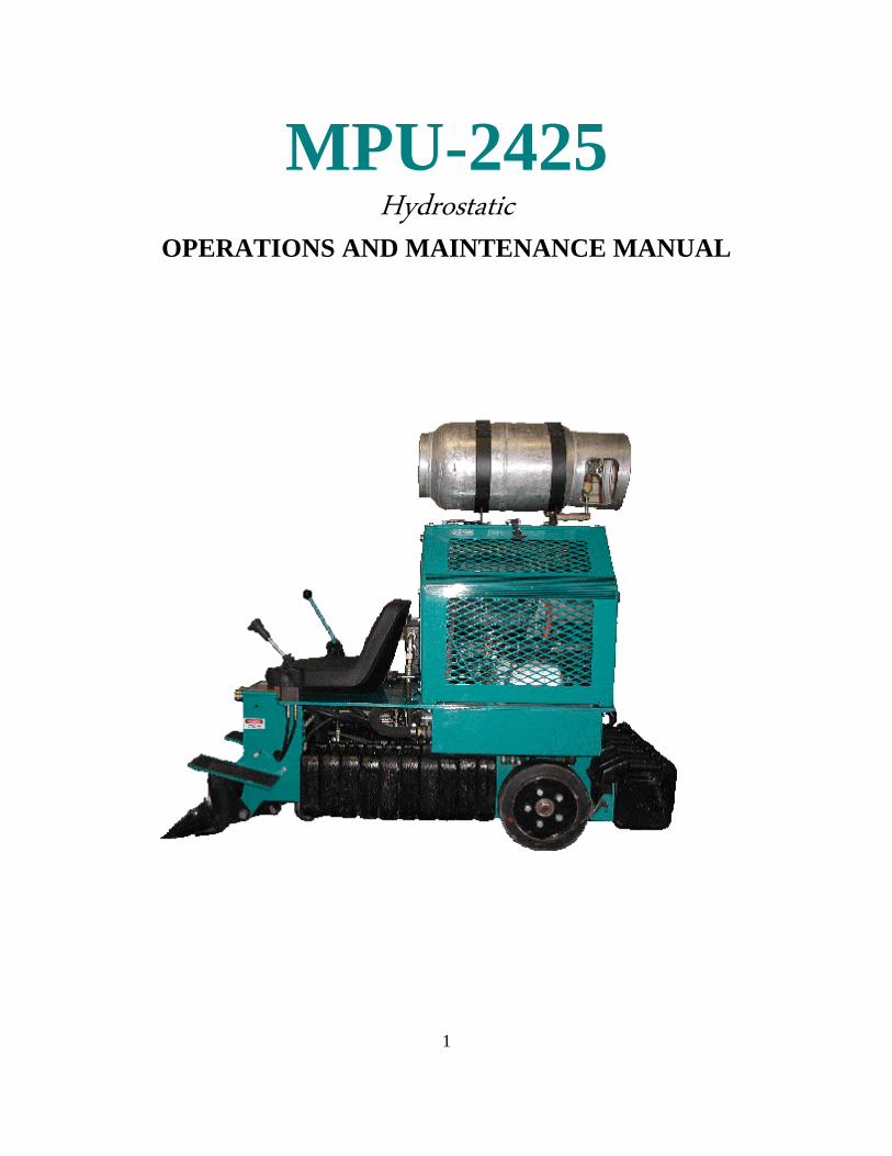
MPU-2425
Hydrostatic OPERATIONS AND MAINTENANCE MANUAL
2
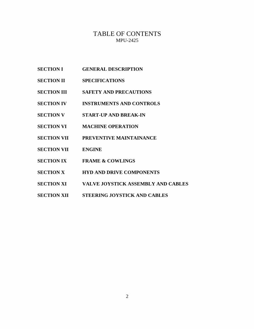
TABLE OF CONTENTS MPU-2425
SECTION I GENERAL DESCRIPTION
SECTION II SPECIFICATIONS
SECTION III SAFETY AND PRECAUTIONS
SECTION IV INSTRUMENTS AND CONTROLS
SECTION V START-UP AND BREAK-IN
SECTION VI MACHINE OPERATION
SECTION VII PREVENTIVE MAINTAINANCE
SECTION VII ENGINE
SECTION IX FRAME & COWLINGS
SECTION X HYD AND DRIVE COMPONENTS
SECTION XI VALVE JOYSTICK ASSEMBLY AND CABLES
SECTION XII STEERING JOYSTICK AND CABLES
3
OPERATIONS
AND
MAINTENANCE MANUAL
______________________________
CUSTOMER
______________________________
SERIAL NUMBER
______________________________
DATE SHIPPED
4
SECTION I
GENERAL DESCRIPTION
MPU-2425
The MPU-2425 is operated by a propane-powered engine, driving
a tandem hydrostatic pump system, creating a (skid-steer) zero turn
radius drive train.
Surface covering and coatings are removed by lowering a weighted
blade onto the surface and moving forward under a high torque drive
system. The surface coating is removed by a flexible sharpened blade
conforming to the floor surface, with the weight of the machine holding
the blade firmly to the floor. The weight does not allow the blade to lift
or ride over well-adhered surface coating material, thus lifting the off
the floor coating.
After layers of carpet or laminates are removed the machine can
be connected to a grinder or slicer attachment to either clean up
adhesives or remove stubborn coatings.
5
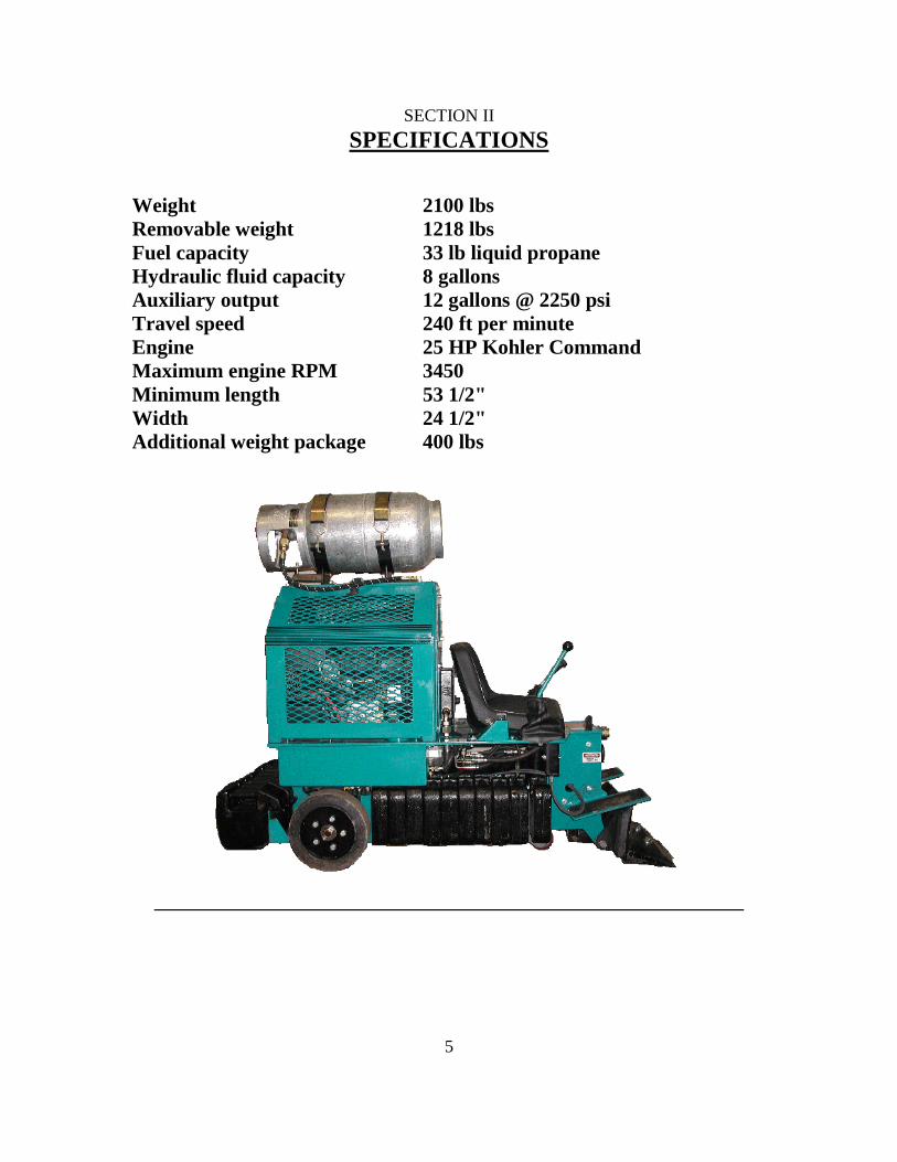
SECTION II
SPECIFICATIONS
Weight 2100 lbs
Removable weight 1218 lbs
Fuel capacity 33 lb liquid propane
Hydraulic fluid capacity 8 gallons
Auxiliary output 12 gallons @ 2250 psi
Travel speed 240 ft per minute
Engine 25 HP Kohler Command
Maximum engine RPM 3450
Minimum length 53 1/2"
Width 24 1/2"
Additional weight package 400 lbs

6
SAFETY
WARNING
CARBON MONOXIDE
can cause severe nausea,
fainting or death.
Do not operate engine in
closed or confined area
without proper ventilation.
7
SECTION III
SAFETY AND PRECAUTIONS
Before operating the MPU-2425 please read the entire operation and safety manual with
complete understanding of the safety section. If you have any questions on safety and
precautions please call 1-405-601-3739.
There are several advantages to an effective safety program which include: lower
operating costs, lower workman compensations, less work time lost, high employee
morale, and less problems. No one can work safely without knowing what precautions to
take to insure personal safety. Operators must know what equipment to wear, which job
practices are safe and which are not, and must be aware of what hazards are possible in
the work area. A regular schedule of Preventive Maintenance on your equipment is the
best protection against unpleasant surprises that slow production and sometimes result in
injuries. Here are a few suggested safety tips.
1. The first step before any maintenance or inspection takes place should be to stop
the engine and disconnect the battery terminals.
2. Wear proper eye and ear protection and heavy duty work gloves at all times.
3. Practice good Preventive Maintenance.
4. Practice good housekeeping.
5. Allow the MPU-2425 to come to a complete stop, turn off engine, and chock rear
wheels before performing any maintenance procedures.
6. Replace worn parts when necessary.
7. Do not reach into blade or control arm areas while machine is in operation.
8. Do not attempt to open any access door until the machine has come to a complete
stop and the engine and propane is turned off.
9. Be sure all electrical inspections or changes are done by a qualified electrician.
10. Loose surface coating can cause dangerous footing. Always be alert and careful.
11. After replacing parts be sure all tools used are removed from the machine. Be
sure all bolts and nuts are tightened. The loose connection of a rotating part could
cause the part to fly off with explosive force, causing serious damage to the
equipment and possible injury to the operator.
12. Always lower blade to the ground when the machine is unoccupied by the
operator. Serious bodily injury may result if arms are not in the lowered position
when not occupied.
13. Never allow unauthorized personnel or the general public into the work area.
14. The work area should be barricaded off to adequately keep all untrained persons
out of the work site. If an unauthorized person enters the work area, stop the
machine immediately and do not restart the machinery until they have left the
work area.
15. Always allow a 200-foot buffer safety zone around all surface preparation
activity.
8
16. Always run the MPU-2425 in a well-ventilated area, with an approved OSHA air-
monitoring system in place at all times.
17. Read and obey all safety labels placed on the machinery at all times. If safety
labels have been destroyed or removed call 1-405-601-3739 for free replacement
prior to operating the machinery.
18. The MPU-2425 is not a toy. All operators must be over 18 years of age and must
have read and reviewed the safety and procedures manual before operating the
machinery.
19. The MPU-2425 is designed for surface preparation ONLY. It is not intended for
towing, pushing or any other procedure not described in this manual.
20. Propane systems should be checked and documented twice yearly by a certified
propane professional for leaks or damaged parts. If a propane leak is detected
leave the machine immediately and seek assistance from a propane professional.
Do not use or restart machinery until it is determined safe.
21. Horseplay and or high speed cornering is not allowed with this machine and could
cause rollover resulting in injury or death.
22. No smoking or open flame is allowed while machinery is running or within 50
feet of the machine.
23. Operator must be sober and not under the influence of drugs or medication and
under full control of all bodily senses while operating this or any machinery.
24. When transporting the MPU-2425, it is recommended to use a low bed tilt trailer.
This procedure insures the wheels do not leave a stable surface.
25. All MPU-2425 operators must receive safety training before performing any
functions with the machine. OEM Products offers a free 8- hour safety,
maintenance and orientation seminar at its facility in Oklahoma City, OK.
New owners and operators are advised to call 1-405-601-3739 for an
appointment.
9
SECTION IV
Instruments and Controls
View # 1
Top view of MPU-2425 machine
View # 2
Left side view of MPU-2425 machine
View #3
Right side view of MPU-2425 machine
View #4
Front view of MPU-2425 machine
10
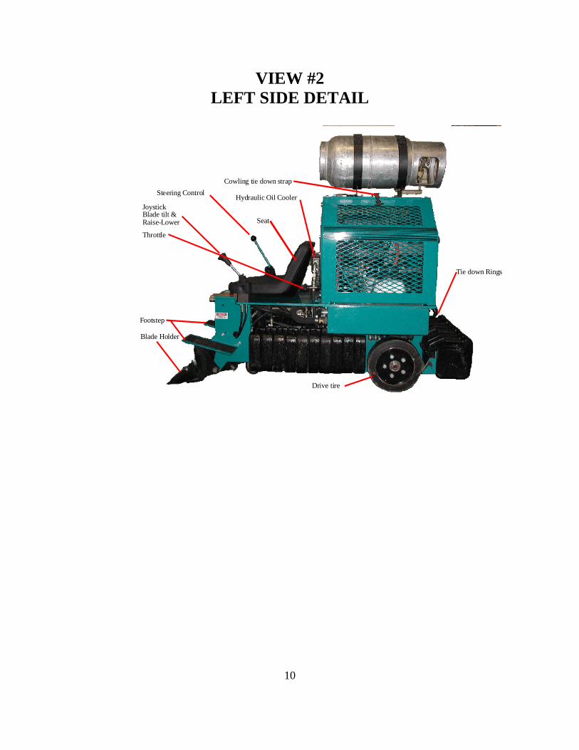
VIEW #2
LEFT SIDE DETAIL
Steering Control
JoystickBlade tilt &Raise-Lower
Throttle
Footstep
Cowling tie down strap
Drive tire
Seat
Blade Holder
Hydraulic Oil Cooler
Tie down Rings
11
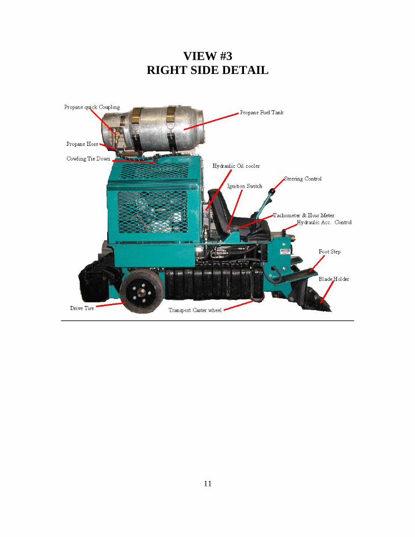
VIEW #3
RIGHT SIDE DETAIL
12
SECTION V
MPU-2425
START-UP AND BREAK-IN
The MPU-2425 has been safety tested and run at our factory prior to shipping. All fluid
levels have been topped off, however, no propane has been added to the tanks for safety
shipment purposes. Before running the MPU-2425 please check the following items that
may have shifted or changed during shipping.
1. Raise engine covers and check oil level.
2. Check air cleaner filter element for snug fit.
3. All battery cable connections are snug.
4. Inspect for major hydraulic oil leaks. Snug hydraulic fittings using two wrenches.
Use caution not to over tighten.
5. Fill propane tank.
6. Mount propane bottle in brackets, be sure bracket alignment pin corresponds with
alignment slot on bottle.
7. Attach propane hose to liquid side of bottle by attaching to the handle valve.
Snug fit the female connector attached to hose and slowly turn valve on. You
should hear gas briefly enter the propane hose. Immediately check for propane
leaks with soapy water solution. If leak persists after retightening the knurled
female connector: STOP, turn off the bottle at valve and seek assistance from
certified propane professional. Serious damage and or an explosion could occur.
8. Check lug bolts for tightness, torque 85-100 lbs.
9. Return all engine guards to proper position.
10. You are now ready to start the engine.
11. Crank the engine by turning the key in the on position. The engine will crank for
3 to 5 seconds while the propane enter the carburetor. If the engine does not start,
turn the key off, wait 1 minute and try again. If again unsuccessful, check
propane valve to be sure it is open. If still unsuccessful turn off propane valve
and seek assistance or call 1-405-601-3739.
12. Once the engine is warming and running, and the operator is safely in the seat, the
machine can be driven.
Please turn to Section V for Machinery Operation.
NEW MACHINE BREAK-IN
Since the MPU-2425 is a very low maintenance and user-friendly machine, the only
break-in is for the Kohler engine. Please refer to the owners manual, included is the
manual and the maintenance schedule found inside the air cleaner plastic cover supplied
by Kohler.
13
SECTION VI
MACHINERY OPERATION
Before reading the machinery operation section, new operators should familiarize
themselves with the 3 diagrams depicting the TOP , LEFT , and RIGHT views of
machine. These drawings show the activation of all moving parts of the MPU-2425.
1. To move the machine: Using the right hand, slowly move the shifter lever in the
desired direction. Forward and left moves the machine to the left, backward and
right reverses the machine to the right. It is just that simple to drive. Speed is
controlled by amount of movement on the joy stick and also by moving travel
Speed lever.
2. The left joystick lever is used to position the blade to the surface. Moving the
lever forward and backward moves the blade up and down. Left and right
movement changes the blade pitch.
3. Throttle control is on the left side of the seat, taking the unit from idle to 3400
RPM. The most optimum speed is 2600 to 3200 RPM. To change RPM of engine
turn throttle knob clockwise to lower RPM and counterclockwise to raise RPM.
4. A cooling fan will run behind the seat when engine is running to keep hydraulic
oil cool.
5. Hydraulic reservoir is accessed by removing right cowling and removing fill cap.
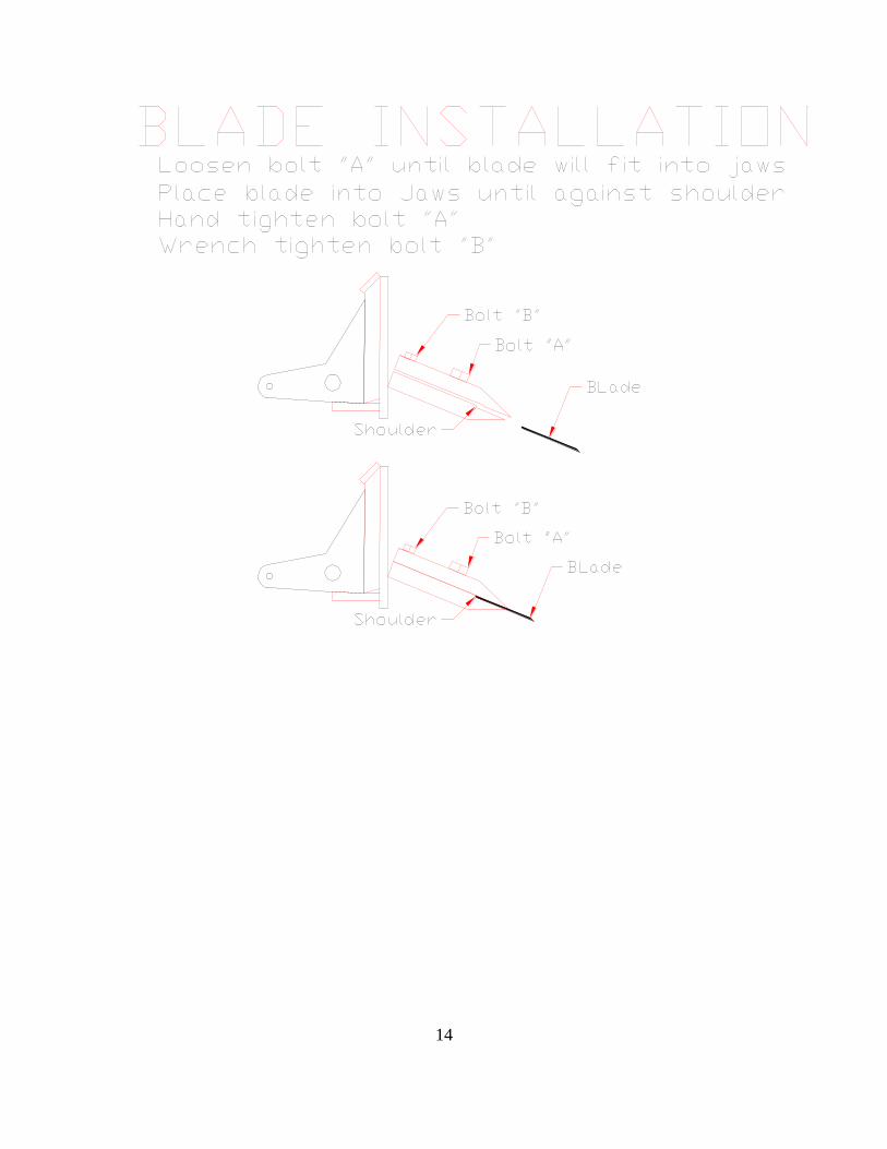
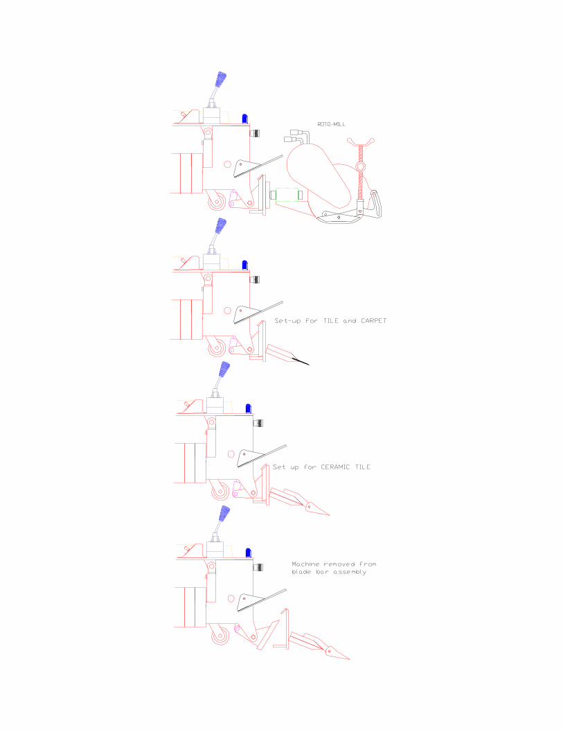
6. To change scraping blades: Stop engine. Loosen the set bolt at the rear of the
Blade holder block using a ¾” open-end wrench. Slide the dull blade out and
Insert a new blade up against the shim stop. Retighten the set bolt and raise the
control arms to remove wooden block. Lower control arms and resume scraping.
The large 1 1’8” blade holder bolt should not need to be more that hand tight.
With a little practice you should be able to change blades in 15 seconds. Dull
blades can be resharpened and reused many times.
SEE DRAWING OF BLADE CHANGE PROCEDURE 3. Operators should lower the blade by pressing the left hand lever forward each
time they get off the machine. This safety practice eliminates possible bodily
injury from lowering the blade by unauthorized operators.
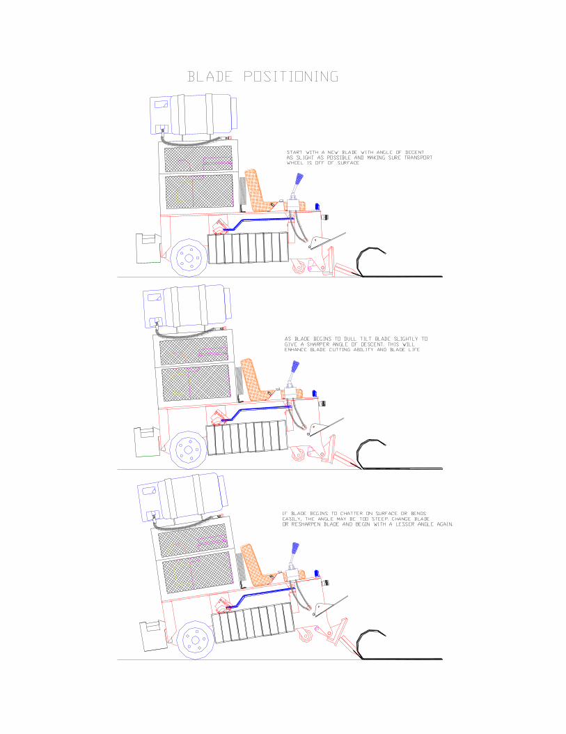
7. The transport caster should not be in contact with the floor while scraping. It will
lift off the floor when blade is lowered. Caster contact with the floor while
scraping will negatively affect scraper productivity and steering.
4. Do not transport machine with front of machine off the surface of floor higher
than 1/2" or irreparable damage to lift cylinder will result.
See illustration of correct scraping procedures.
14
15
16
17
SECTION VII
Preventative Maintenance
FOLLOW KOHLER SUGGESTED SCHEDULE FOR ENGINE
MAINTAINANCE
1. DAILY MAINTENANCE
CHECK HYDRAULIC OIL
INSPECT FOR HYDRAULIC OIL
LEAKS
INSPECT FOR PROPANE SYSTEM
LEAKS
SERVICE ENGINE AIR CLEANER
RETORQUE WHEEL LUG BOLTS
1. 100 HR MAINTENANCE
GREASE CASTER BEARINGS
INSPECT ALL BOLTS AND NUTS
AND TIGHTEN IF NEEDED
2. 400 HR MAINTAINANCE
CHANGE HYDRAULIC OIL WITH:
MOBILE DTE –15M
MOBILE 424 TRACTOR OIL
SUNOCO 2105
USE APPROXIMATLY 8 GAL
CHANGE HYDRAULIC OIL FILTER
18
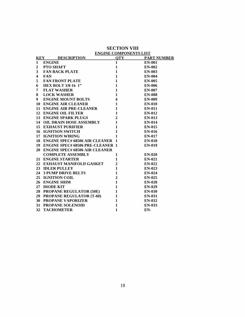
SECTION VIII ENGINE COMPONENTS LIST
KEY DESCRIPTION QTY PART NUMBER
1 ENGINE 1 EN-001
2 PTO SHAFT 1 EN-002
3 FAN BACK PLATE 1 EN-003
4 FAN 1 EN-004
5 FAN FRONT PLATE 1 EN-005
6 HEX BOLT 3/8-16 1” 1 EN-006
7 FLAT WASHER 1 EN-007
8 LOCK WASHER 1 EN-008
9 ENGINE MOUNT BOLTS 4 EN-009
10 ENGINE AIR CLEANER 1 EN-010
11 ENGINE AIR PRE-CLEANER 1 EN-011
12 ENGINE OIL FILTER 1 EN-012
13 ENGINE SPARK PLUGS 2 EN-013
14 OIL DRAIN HOSE ASSEMBLY 1 EN-014
15 EXHAUST PURIFIER 1 EN-015
16 IGNITION SWITCH 1 EN-016
17 IGNITION WIRING 1 EN-017
18 ENGINE SPEC# 68506 AIR CLEANER 1 EN-018
19 ENGINE SPEC# 68506 PRE-CLEANER 1 EN-019
20 ENGINE SPEC# 68506 AIR CLEANER
COMPLETE ASSEMBLY 1 EN-020
21 ENGINE STARTER 1 EN-021
22 EXHAUST MANIFOLD GASKET 2 EN-022
23 IDLER PULLEY 1 EN-023
24 3 PUMP DRIVE BELTS 1 EN-024
25 IGNITION COIL 2 EN-025
26 ENGINE SHIM 1 EN-028
27 DIODE KIT 1 EN-029
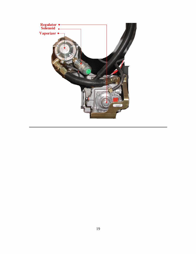
28 PROPANE REGULATOR (50E) 1 EN-030
29 PROPANE REGULATOR (T-60) 1 EN-031
30 PROPANE VAPORIZER 1 EN-032
31 PROPANE SOLENOID 1 EN-033
32 TACHOMETER 1 EN-
19
20
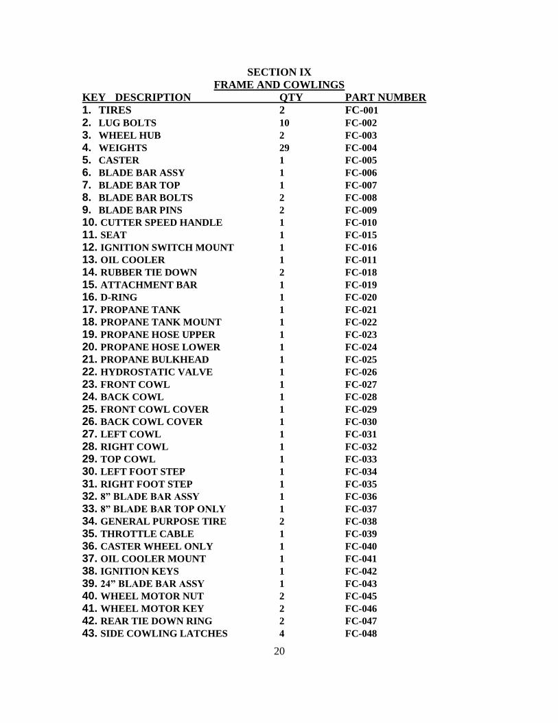
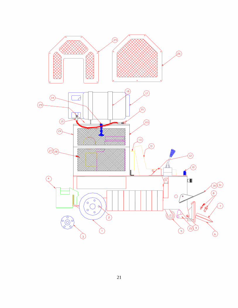
SECTION IX
FRAME AND COWLINGS
KEY DESCRIPTION QTY PART NUMBER
1. TIRES 2 FC-001
2. LUG BOLTS 10 FC-002
3. WHEEL HUB 2 FC-003
4. WEIGHTS 29 FC-004
5. CASTER 1 FC-005
6. BLADE BAR ASSY 1 FC-006
7. BLADE BAR TOP 1 FC-007
8. BLADE BAR BOLTS 2 FC-008
9. BLADE BAR PINS 2 FC-009
10. CUTTER SPEED HANDLE 1 FC-010
11. SEAT 1 FC-015
12. IGNITION SWITCH MOUNT 1 FC-016
13. OIL COOLER 1 FC-011
14. RUBBER TIE DOWN 2 FC-018
15. ATTACHMENT BAR 1 FC-019
16. D-RING 1 FC-020
17. PROPANE TANK 1 FC-021
18. PROPANE TANK MOUNT 1 FC-022
19. PROPANE HOSE UPPER 1 FC-023
20. PROPANE HOSE LOWER 1 FC-024
21. PROPANE BULKHEAD 1 FC-025
22. HYDROSTATIC VALVE 1 FC-026
23. FRONT COWL 1 FC-027
24. BACK COWL 1 FC-028
25. FRONT COWL COVER 1 FC-029
26. BACK COWL COVER 1 FC-030
27. LEFT COWL 1 FC-031
28. RIGHT COWL 1 FC-032
29. TOP COWL 1 FC-033
30. LEFT FOOT STEP 1 FC-034
31. RIGHT FOOT STEP 1 FC-035
32. 8” BLADE BAR ASSY 1 FC-036
33. 8” BLADE BAR TOP ONLY 1 FC-037
34. GENERAL PURPOSE TIRE 2 FC-038
35. THROTTLE CABLE 1 FC-039
36. CASTER WHEEL ONLY 1 FC-040
37. OIL COOLER MOUNT 1 FC-041
38. IGNITION KEYS 1 FC-042
39. 24” BLADE BAR ASSY 1 FC-043
40. WHEEL MOTOR NUT 2 FC-045
41. WHEEL MOTOR KEY 2 FC-046
42. REAR TIE DOWN RING 2 FC-047
43. SIDE COWLING LATCHES 4 FC-048
21
22
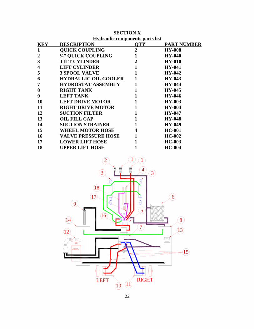
SECTION X
Hydraulic components parts list
KEY DESCRIPTION QTY PART NUMBER
1 QUICK COUPLING 2 HY-008
2 ¼” QUICK COUPLING 1 HY-040
3 TILT CYLINDER 2 HY-010
4 LIFT CYLINDER 1 HY-041
5 3 SPOOL VALVE 1 HY-042
6 HYDRAULIC OIL COOLER 1 HY-043
7 HYDROSTAT ASSEMBLY 1 HY-044
8 RIGHT TANK 1 HY-045
9 LEFT TANK 1 HY-046
10 LEFT DRIVE MOTOR 1 HY-003
11 RIGHT DRIVE MOTOR 1 HY-004
12 SUCTION FILTER 1 HY-047
13 OIL FILL CAP 1 HY-048
14 SUCTION STRAINER 1 HY-049
15 WHEEL MOTOR HOSE 4 HC-001
16 VALVE PRESSURE HOSE 1 HC-002
17 LOWER LIFT HOSE 1 HC-003
18 UPPER LIFT HOSE 1 HC-004
FILTER
SUCTION FILTER
HEAD
25 MICRON
12
34
5
6
7
9
10 11
12 13
14
1
8
3
LEFT RIGHT
15
16
17
18
23
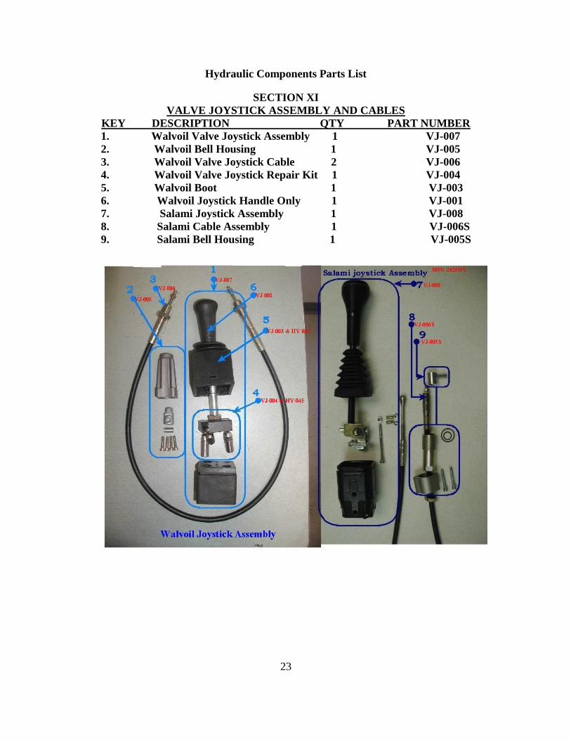
Hydraulic Components Parts List
SECTION XI
VALVE JOYSTICK ASSEMBLY AND CABLES
KEY DESCRIPTION QTY PART NUMBER
1. Walvoil Valve Joystick Assembly 1 VJ-007
2. Walvoil Bell Housing 1 VJ-005
3. Walvoil Valve Joystick Cable 2 VJ-006
4. Walvoil Valve Joystick Repair Kit 1 VJ-004
5. Walvoil Boot 1 VJ-003
6. Walvoil Joystick Handle Only 1 VJ-001
7. Salami Joystick Assembly 1 VJ-008
8. Salami Cable Assembly 1 VJ-006S
9. Salami Bell Housing 1 VJ-005S
24
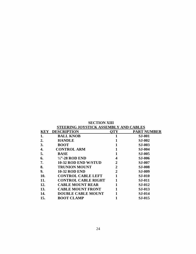
SECTION XIII
STEERING JOYSTICK ASSEMBLY AND CABLES
KEY DESCRIPTION QTY PART NUMBER
1. BALL KNOB 1 SJ-001
2. HANDLE 1 SJ-002
3. BOOT 1 SJ-003
4. CONTROL ARM 1 SJ-004
5. BASE 1 SJ-005
6. ¼”-28 ROD END 4 SJ-006
7. 10-32 ROD END W/STUD 2 SJ-007
8. TRUNION MOUNT 2 SJ-008
9. 10-32 ROD END 2 SJ-009
10. CONTROL CABLE LEFT 1 SJ-010
11. CONTROL CABLE RIGHT 1 SJ-011
12. CABLE MOUNT REAR 1 SJ-012
13. CABLE MOUNT FRONT 1 SJ-013
14. DOUBLE CABLE MOUNT 1 SJ-014
15. BOOT CLAMP 1 SJ-015
25