Embed Size (px)
Citation preview

CATALOG
MQL ModularAir-Handling Units
2 ENVIRO-TEC
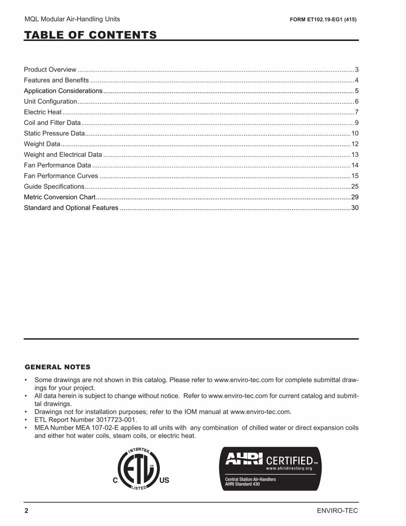
MQL Modular Air-Handling Units FORM ET102.19-EG1 (415)
TABLE OF CONTENTS
GENERAL NOTES
• Some drawings are not shown in this catalog. Please refer to www.enviro-tec.com for complete submittal draw-ings for your project.
• All data herein is subject to change without notice. Refer to www.enviro-tec.com for current catalog and submit-tal drawings.
• Drawings not for installation purposes; refer to the IOM manual at www.enviro-tec.com.• ETL Report Number 3017723-001.• MEA Number MEA 107-02-E applies to all units with any combination of chilled water or direct expansion coils
and either hot water coils, steam coils, or electric heat.
Product Overview ......................................................................................................................................................3Features and Benefits ...............................................................................................................................................4Application Considerations ........................................................................................................................................5Unit Configuration ......................................................................................................................................................6Electric Heat ..............................................................................................................................................................7Coil and Filter Data ....................................................................................................................................................9Static Pressure Data................................................................................................................................................10Weight Data .............................................................................................................................................................12Weight and Electrical Data ......................................................................................................................................13Fan Performance Data ............................................................................................................................................14Fan Performance Curves ........................................................................................................................................15Guide Specifications ................................................................................................................................................25Metric Conversion Chart ..........................................................................................................................................29Standard and Optional Features .............................................................................................................................30
ENVIRO-TEC 3
MQL Modular Air-Handling Units FORM ET102.19-EG1 (415)
PRODUCT OVERVIEW
The Perfect Solution for Schools, Hospitals, and Commercial Buildings.The flexibility of the Model MQL Air-Handling Unit allows you to design the unit to meet the specific project needs. The MQL design allows you to configure draw thru applications in horizontal, vertical, and footprint- saving arrange-ments. From basic air-handling to the sophisticated isolation room systems required to meet challenging indoor air quality (IAQ), controls, and acoustic (sound sensitive) projects – the Model MQL Air-Handling Unit is your solution!
STANDARD FEATURES
• Modular construction allows for footprint saving arrangements including stacking modules in two-high configu-ration.
• IAQ galvanized drain pans are double sloped to prevent standing water and minimize microbial growth. Stainless steel drain pans are available.
• Removable access panels for improved accessibility, cleanability, and serviceability. Hinged access doors with quick action latches are available.
• Single point power connection – even with draw thru or blow thru electric heat – simplifies installation. Fan motors are factory mounted and wired to the junction box.
• Available in nine sizes, from 600 to 10,000 CFM.• Internal spring isolation standard on all unit sizes 02 - 17.• Single wall and double wall-galvanized construction are available. Double wall construction enhances indoor
air quality, protects insulation, and provides the ability to clean the inside of the unit.
OPTIONAL FEATURES
• Factory-packaged air-handling units are available with starters or variable frequency drives, factory mounted and wired. Simply connect power, piping, and ductwork, and the units are ready for operation. An excellent way to minimize installation time, coordination and costs, while increasing reliability.
• Quiet, flexible, acoustical discharge plenums may be used for sound sensitive projects.• Exhaust / Return Fan with Economizer Sections for use with IAQ applications (“free” heating and cooling – cost
savings for space conditioning).• Customized Options including: - Direct drive plenum fans - High efficiency filters - Double wall perforated lining - External face and bypass dampers - Inspection windows
4 ENVIRO-TEC
MQL Modular Air-Handling Units FORM ET102.19-EG1 (415)
FEATURES AND BENEFITS
DESIGNED FOR MAXIMUM FLEXIBILITY
The ENVIRO-TEC Model MQL Air-Handling Unit is designed to maximize flexibility of selection and instal-lation.
The unit is also designed to exceed the stringent qual-ity standards of the institutional market, while remaining cost competitive in the light commercial segment of themarket.
ENVIRO-TEC Model MQL sets the new standard for quality, flexibility, and competitive pricing.
FOR THE BUILDING DESIGNER:
OPTIONAL COMPONENTS MEAN FLEXIBILITYThe extensive variety of standard options available on the MQL is where you find the versatility to fit any HVAC system designer’s needs.
Options include: Mixing boxes with standard low leak dampers, High efficiency filter sections for 2” prefilter and 4” final filter, blow thru electric heat with single pointpower connection. All electric heat units are listed with ETL as an assembly and carry the cETL label.
High Efficiency motors, starters, disconnects and fusing mean easier coordination between mechanical and electrical trades.
Coil options allow for 4 or 6 row cooling coils. Water coils have optional circuiting that can be used to reduce Water Pressure Drop, which may also allow for pipe size reductions and lower material cost. Hot Water orStandard Steam coils may be placed in the Preheat or Reheat position.
All Model MQL Air-Handling Units have the option of foil faced insulation.
FOR THE CONTRACTOR:
LOWER INSTALLED COSTModel MQL Air-Handling Units are shipped completely assembled, reducing field installation time and labor. All units are thoroughly inspected and tested prior to shipment, eliminating potential problems at startup. Motor wiring is brought to a junction box on the outside of the unit casing, reducing electrical hook-up time.
A wide variety of fan discharge configurations allow for increased flexibility and easier installation on the job-site, resulting in cost reductions by eliminating expensive elbows, etc.
FOR THE OWNER:
QUALITY PRODUCTModel MQL Air-Handling Units are built from G60 minimum spangled galvanized steel with a chromate coating. This metal surpasses the ASTM 125 hour salt spray test for corrosion and rust. Standard insulation is 1 inch fiberglass insulation which is glued and pin spotted for maximum positive adhesion. Insulation complies with UL 181 and NFPA 90A.
All units, with or without Electric Heat, are ETL listed and labeled. All wiring is in compliance with NEC, assuring safety and quality for the owner.
ENVIRO-TEC 5
MQL Modular Air-Handling Units FORM ET102.19-EG1 (415)
Model MQL Air-Handling Units offer a wide range of application flexibility, while maintaining a simple, easy to install unit design. These units are intended to pro-vide comfort cooling and heating within a small footprint. They may be applied in many types of building struc-tures including schools, office buildings, hospitals, condominiums, assisted living facilities, apartments or stores. Applications can be constant or variable volume.
There are many applications in which the MQL product can be utilized. Some examples include:
Constant volume applications• Two-pipe hydronic system for cooling and/or heating• Two-pipe hydronic cooling system with electric heat• Four-pipe system with dedicated heating and cool-
ing coils• Direct Expansion (DX) split systems with hydronic
heat• Direct Expansion (DX) split systems with electric
heat
Variable volume applications• Two-pipe hydronic system for cooling and/or heat-
ing.• Two-pipe hydronic cooling system with electric heat.• Four-pipe system with dedicated heating and cool-
ing coils.
ACOUSTICS
Control of noise within both occupied and unoccupied spaces has become increasingly important to designers and building owners/ occupants. Proper considerationmust be given to placement of indoor air conditioning units, particularly in the occupied space.
Inherent flexibility of the fan and coil combination in the vertical configuration allows application in sound-sen-sitive areas. In such instances, a fan running at low speed with a high capacity coil normally yields satisfac-tory results. It also may be desirable to select a larger nominal capacity unit and operate it at a less than nominal airflow for further acoustic benefit.
Three phase motors are recommended for sound-sensitive applications to avoid potential single phase motor hum. Unit operation in the stall region of the fan curve is not recommended since it may cause unsat-isfactory noise levels and excessive unit vibration.
INSTALLATION
These floor mounted or ceiling hung units can be installed on a base rail or hanger rods at the corner points. All units have internally isolated fan decks; therefore, flex connections are not required, which will reduce installation costs. One of the most important and basic IAQ issues is condensate management. The first step to ensure trouble-free operation is proper installation. It is very important that the unit be mount-ed high enough so that the condensate drain from the unit may be properly trapped. Please refer to the MQL IOM Manual at www.enviro-tec.com for specifics on this issue. As with all HVAC systems, these units should be installed according to all applicable ASHRAE stan-dards, SMACNA and local code requirements.
OPERATING LIMITATIONS
Units must not be operated above maximum fan speed or unit airflow as listed in the Fan Performance section of this catalog. Unit operation at greater than maximum fan speed could drastically reduce bearing life and may result in a catastrophic failure. Operating at greater than the maximum allowable airflow in the cooling mode may result in unsatisfactory operation due to moisture carry over from the coil. In addition, it is often not eco-nomical to operate a unit at its maximum fan speed due to the greater motor power requirements.
Units with electric heat should not be operated with leaving air temperature greater than 104°F, to prevent excessive leaving air temperatures and electric heat limit trips. A hydronic (or steam) coil and electric heat should not be operated simultaneously to prevent excessive leaving air temperatures and limit trips. Electric heat units are equipped with a lockout switch that disables the electric heater if the temperature of the hydronic (or steam) coil is greater than 104°F (40°C).
Water coils must not be operated above a fluid veloc-ity of 8 ft./sec. to reduce the possibility of velocity induced erosion and flow noise. Water coils must not be operated below a fluid velocity of 1 ft./sec. to prevent degraded coil performance caused by laminar flow. These high or low fluid flow rates may not be included in the AHRI coil certification.
APPLICATION CONSIDERATIONS
6 ENVIRO-TEC
MQL Modular Air-Handling Units FORM ET102.19-EG1 (415)
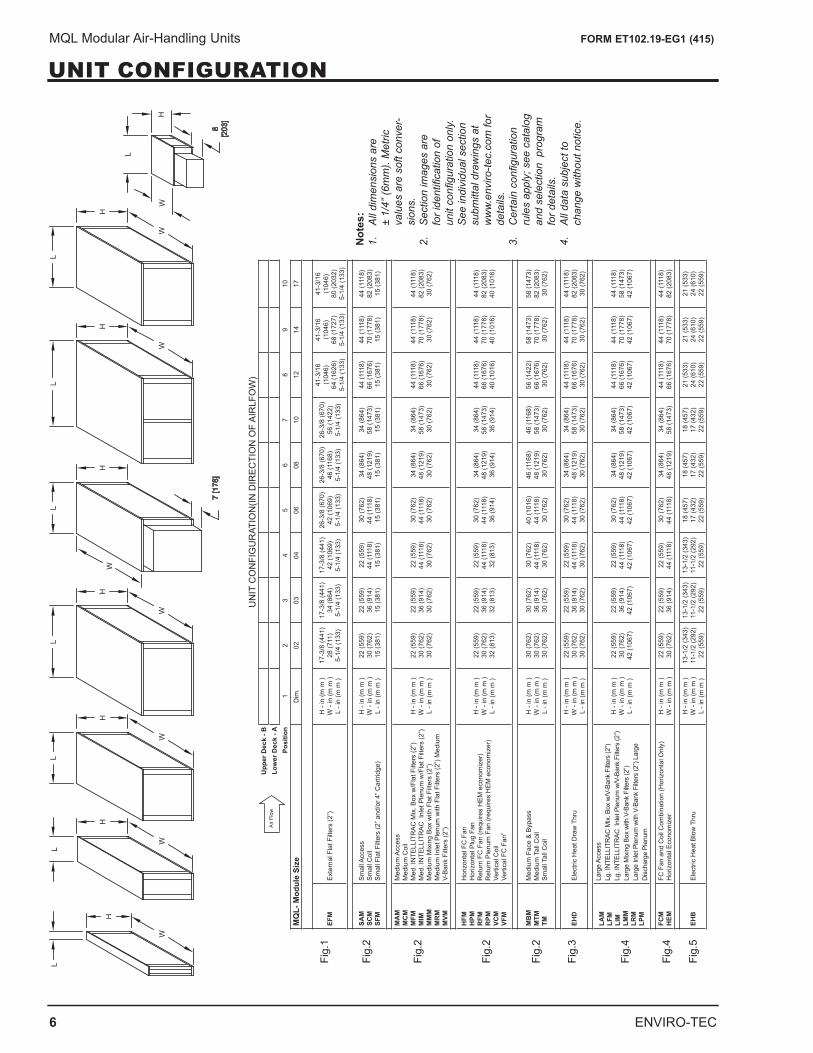
UNIT CONFIGURATION
Fig.
1
Fig.
2
Fig.
2
Fig.
2
Fig.
2
Fig.
3
Fig.
4
Fig.
4
Fig.
5
Not
es:
1.
All
dim
ensi
ons
are
± 1/
4” (6
mm
). M
etric
va
lues
are
sof
t con
ver-
sion
s.2.
S
ectio
n im
ages
are
fo
r ide
ntifi
catio
n of
un
it co
nfigu
ratio
n on
ly.
See
indi
vidu
al s
ectio
n su
bmitt
al d
raw
ings
at
ww
w.e
nviro
-tec.
com
for
deta
ils.
3.
Cer
tain
con
figur
atio
n ru
les
appl
y; s
ee c
atal
og
and
sele
ctio
n p
rogr
am
for d
etai
ls.
4.
All
data
sub
ject
to
chan
ge w
ithou
t not
ice.
UN
IT C
ON
FIG
UR
ATIO
N(IN
DIR
ECTI
ON
OF
AIR
LFO
W)
Upp
er D
eck
- BLo
wer
Dec
k - A
Posi
tion
12
34
56
78
910
MQ
L- M
odul
e Si
zeD
im.
0203
0406
0810
1214
17
EFM
Exte
rnal
Fla
t Filt
ers
(2”)
H -
in (m
m )
W -
in (m
m )
L - i
n (m
m )
17-3
/8 (4
41)
28 (7
11)
5-1/
4 (1
33)
17-3
/8 (4
41)
34 (8
64)
5-1/
4 (1
33)
17-3
/8 (4
41)
42 (1
069)
5-
1/4
(133
)
26-3
/8 (6
70)
42 (1
069)
5-
1/4
(133
)
26-3
/8 (6
70)
46 (1
168)
5-
1/4
(133
)
26-3
/8 (6
70)
56 (1
422)
5-
1/4
(133
)
41-3
/16
(104
6)
64 (1
626)
5-
1/4
(133
)
41-3
/16
(104
6)
68 (1
727)
5-
1/4
(133
)
41-3
/16
(104
6)
80 (2
032)
5-
1/4
(133
)
SAM
SC
M
SFM
Smal
l Acc
ess
Smal
l Coi
l Sm
all F
lat F
ilter
s (2
” and
/or 4
” Car
tridg
e)
H -
in (m
m )
W -
in (m
m )
L - i
n (m
m )
22 (5
59)
30 (7
62)
15 (3
81)
22 (5
59)
36 (9
14)
15 (3
81)
22 (5
59)
44 (1
118)
15
(381
)
30 (7
62)
44 (1
118)
15
(381
)
34 (8
64)
48 (1
219)
15
(381
)
34 (8
64)
58 (1
473)
15
(381
)
44 (1
118)
66
(167
6)
15 (3
81)
44 (1
118)
70
(177
8)
15 (3
81)
44 (1
118)
82
(208
3)
15 (3
81)
MA
MM
CM
M
FM
MIM
M
MM
M
RM
M
VM
Med
ium
Acc
ess
Med
ium
Coi
l M
ed. I
NTE
LLIT
RAC
Mix
. Box
w/F
lat F
ilter
s (2
”) M
ed. I
NTE
LLIT
RAC
Inl
et P
lenu
m w
/Fla
t Filt
ers
(2”)
Med
ium
Mix
ing
Box
with
Fla
t Filt
ers
(2”)
Med
ium
Inle
t Ple
num
with
Fla
t Filt
ers
(2”)
Med
ium
V-
Bank
Filt
ers
(2”)
H -
in (m
m )
W -
in (m
m )
L - i
n (m
m )
22 (5
59)
30 (7
62)
30 (7
62)
22 (5
59)
36 (9
14)
30 (7
62)
22 (5
59)
44 (1
118)
30
(762
)
30 (7
62)
44 (1
118)
30
(762
)
34 (8
64)
48 (1
219)
30
(762
)
34 (8
64)
58 (1
473)
30
(762
)
44 (1
118)
66
(167
6)
30 (7
62)
44 (1
118)
70
(177
8)
30 (7
62)
44 (1
118)
82
(208
3)
30 (7
62)
HFM
H
PM
RFM
R
PM
VCM
VF
M
Hor
izon
tal F
C F
anH
oriz
onta
l Plu
g Fa
n R
etur
n FC
Fan
(req
uire
s H
EM e
cono
miz
er)
Ret
urn
Plen
um F
an (r
equi
res
HEM
eco
nom
izer
)Ve
rtica
l Coi
l Ve
rtica
l FC
Fan
”
H -
in (m
m )
W -
in (m
m )
L - i
n (m
m )
22 (5
59)
30 (7
62)
32 (8
13)
22 (5
59)
36 (9
14)
32 (8
13)
22 (5
59)
44 (1
118)
32
(813
)
30 (7
62)
44 (1
118)
36
(914
)
34 (8
64)
48 (1
219)
36
(914
)
34 (8
64)
58 (1
473)
36
(914
)
44 (1
118)
66
(167
6)
40 (1
016)
44 (1
118)
70
(177
8)
40 (1
016)
44 (1
118)
82
(208
3)
40 (1
016)
MB
M
MTM
TM
Med
ium
Fac
e &
Bypa
ss
Med
ium
Tal
l Coi
l Sm
all T
all C
oil
H -
in (m
m )
W -
in (m
m )
L - i
n (m
m )
30 (7
62)
30 (7
62)
30 (7
62)
30 (7
62)
36 (9
14)
30 (7
62)
30 (7
62)
44 (1
118)
30
(762
)
40 (1
016)
44
(111
8)
30 (7
62)
46 (1
168)
48
(121
9)
30 (7
62)
46 (1
168)
58
(147
3)
30 (7
62)
56 (1
422)
66
(167
6)
30 (7
62)
58 (1
473)
70
(177
8)
30 (7
62)
58 (1
473)
82
(208
3)
30 (7
62)
EHD
Elec
tric
Hea
t Dra
w T
hru
H -
in (m
m )
W -
in (m
m )
L - i
n (m
m )
22 (5
59)
30 (7
62)
30 (7
62)
22 (5
59)
36 (9
14)
30 (7
62)
22 (5
59)
44 (1
118)
30
(762
)
30 (7
62)
44 (1
118)
30
(762
)
34 (8
64)
48 (1
219)
30
(762
)
34 (8
64)
58 (1
473)
30
(762
)
44 (1
118)
66
(167
6)
30 (7
62)
44 (1
118)
70
(177
8)
30 (7
62)
44 (1
118)
82
(208
3)
30 (7
62)
LAM
LFM
LI
M
LMM
LR
M
LPM
Larg
e Ac
cess
Lg
. IN
TELL
ITR
AC M
ix. B
ox w
/V-B
ank
Filte
rs (2
”) Lg
. IN
TELL
ITR
AC I
nlet
Ple
num
w/V
-Ban
k Fi
lters
(2”)
Larg
e M
ixing
Box
with
V-B
ank
Filte
rs (2
”) La
rge
Inle
t Ple
num
with
V-B
ank
Filte
rs (2
”) La
rge
Disc
harg
e Pl
enum
H -
in (m
m )
W -
in (m
m )
L - i
n (m
m )
22 (5
59)
30 (7
62)
42 (1
067)
22 (5
59)
36 (9
14)
42 (1
067)
22 (5
59)
44 (1
118)
42
(106
7)
30 (7
62)
44 (1
118)
42
(106
7)
34 (8
64)
48 (1
219)
42
(106
7)
34 (8
64)
58 (1
473)
42
(106
7)
44 (1
118)
66
(167
6)
42 (1
067)
44 (1
118)
70
(177
8)
42 (1
067)
44 (1
118)
58
(147
3)
42 (1
067)
FCM
H
EMFC
Fan
and
Coi
l Com
bina
tion
(Hor
izon
tal O
nly)
H
oriz
onta
l Eco
nom
izer
H -
in (m
m )
W -
in (m
m )
22 (5
59)
30 (7
62)
22 (5
59)
36 (9
14)
22 (5
59)
44 (1
118)
30 (7
62)
44 (1
118)
34 (8
64)
48 (1
219)
34 (8
64)
58 (1
473)
44 (1
118)
66
(167
6)44
(111
8)
70 (1
778)
44 (1
118)
82
(208
3)
EHB
Elec
tric
Hea
t Blo
w T
hru
H -
in (m
m )
W -
in (m
m )
L - i
n (m
m )
13-1
/2 (3
43)
11-1
/2 (2
92)
22 (5
59)
13-1
/2 (3
43)
11-1
/2 (2
92)
22 (5
59)
13-1
/2 (3
43)
11-1
/2 (2
92)
22 (5
59)
18 (4
57)
17 (4
32)
22 (5
59)
18 (4
57)
17 (4
32)
22 (5
59)
18 (4
57)
17 (4
32)
22 (5
59)
21 (5
33)
24 (6
10)
22 (5
59)
21 (5
33)
24 (6
10)
22 (5
59)
21 (5
33)
24 (6
10)
22 (5
59)
Air
Flow
ENVIRO-TEC 7
MQL Modular Air-Handling Units FORM ET102.19-EG1 (415)
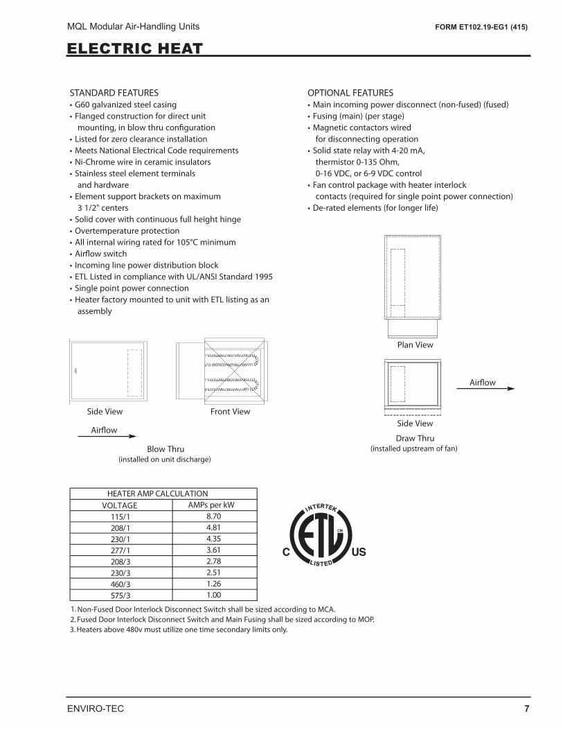
ELECTRIC HEATELECTRIC HEAT • MQL
STANDARD FEATURES• G60 galvanized steel casing• Flanged construction for direct unit
mounting, in blow thru con�guration• Listed for zero clearance installation• Meets National Electrical Code requirements• Ni-Chrome wire in ceramic insulators• Stainless steel element terminals
and hardware• Element support brackets on maximum
3 1/2" centers• Solid cover with continuous full height hinge• Overtemperature protection• All internal wiring rated for 105°C minimum• Air�ow switch• Incoming line power distribution block• ETL Listed in compliance with UL/ANSI Standard 1995• Single point power connection• Heater factory mounted to unit with ETL listing as an
assembly
OPTIONAL FEATURES• Main incoming power disconnect (non-fused) (fused)• Fusing (main) (per stage)• Magnetic contactors wired
for disconnecting operation• Solid state relay with 4-20 mA,
thermistor 0-135 Ohm, 0-16 VDC, or 6-9 VDC control
• Fan control package with heater interlock contacts (required for single point power connection)
• De-rated elements (for longer life)
Blow Thru(installed on unit discharge)
Side View Front View
Air�owDraw Thru
(installed upstream of fan)
Side View
Air�ow
VOLTAGE115/1208/1230/1277/1208/3230/3460/3575/3
4.814.353.61
HEATER AMP CALCULATIONAMPs per kW
8.70
1.00
2.782.511.26
1. Non-Fused Door Interlock Disconnect Switch shall be sized according to MCA.2. Fused Door Interlock Disconnect Switch and Main Fusing shall be sized according to MOP.3. Heaters above 480v must utilize one time secondary limits only.
Plan View
8 ENVIRO-TEC
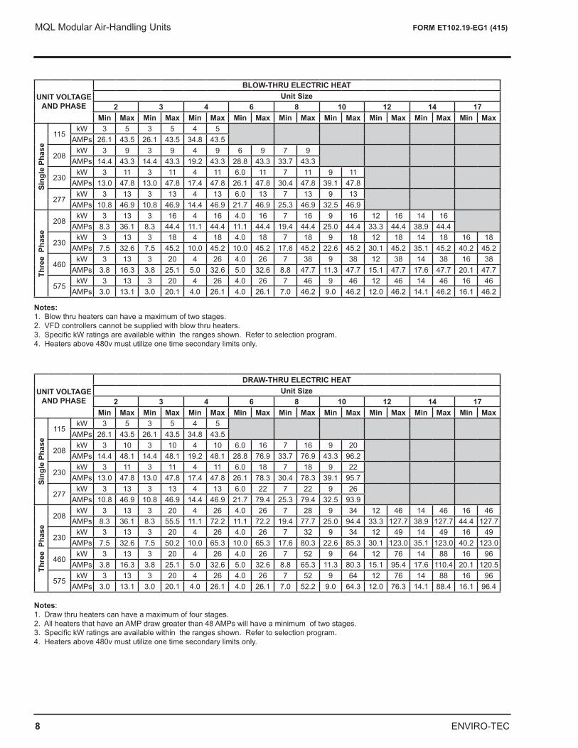
MQL Modular Air-Handling Units FORM ET102.19-EG1 (415)
UNIT VOLTAGE AND PHASE
BLOW-THRU ELECTRIC HEATUnit Size
2 3 4 6 8 10 12 14 17Min Max Min Max Min Max Min Max Min Max Min Max Min Max Min Max Min Max
Sing
le P
hase
115kW 3 5 3 5 4 5
AMPs 26.1 43.5 26.1 43.5 34.8 43.5
208kW 3 9 3 9 4 9 6 9 7 9
AMPs 14.4 43.3 14.4 43.3 19.2 43.3 28.8 43.3 33.7 43.3
230kW 3 11 3 11 4 11 6.0 11 7 11 9 11
AMPs 13.0 47.8 13.0 47.8 17.4 47.8 26.1 47.8 30.4 47.8 39.1 47.8
277kW 3 13 3 13 4 13 6.0 13 7 13 9 13
AMPs 10.8 46.9 10.8 46.9 14.4 46.9 21.7 46.9 25.3 46.9 32.5 46.9
Thre
e P
hase
208kW 3 13 3 16 4 16 4.0 16 7 16 9 16 12 16 14 16
AMPs 8.3 36.1 8.3 44.4 11.1 44.4 11.1 44.4 19.4 44.4 25.0 44.4 33.3 44.4 38.9 44.4
230kW 3 13 3 18 4 18 4.0 18 7 18 9 18 12 18 14 18 16 18
AMPs 7.5 32.6 7.5 45.2 10.0 45.2 10.0 45.2 17.6 45.2 22.6 45.2 30.1 45.2 35.1 45.2 40.2 45.2
460kW 3 13 3 20 4 26 4.0 26 7 38 9 38 12 38 14 38 16 38
AMPs 3.8 16.3 3.8 25.1 5.0 32.6 5.0 32.6 8.8 47.7 11.3 47.7 15.1 47.7 17.6 47.7 20.1 47.7
575kW 3 13 3 20 4 26 4.0 26 7 46 9 46 12 46 14 46 16 46
AMPs 3.0 13.1 3.0 20.1 4.0 26.1 4.0 26.1 7.0 46.2 9.0 46.2 12.0 46.2 14.1 46.2 16.1 46.2
Notes: 1. Blow thru heaters can have a maximum of two stages. 2. VFD controllers cannot be supplied with blow thru heaters. 3. Specific kW ratings are available within the ranges shown. Refer to selection program.4. Heaters above 480v must utilize one time secondary limits only.
UNIT VOLTAGE AND PHASE
DRAW-THRU ELECTRIC HEATUnit Size
2 3 4 6 8 10 12 14 17Min Max Min Max Min Max Min Max Min Max Min Max Min Max Min Max Min Max
Sing
le P
hase
115kW 3 5 3 5 4 5
AMPs 26.1 43.5 26.1 43.5 34.8 43.5
208kW 3 10 3 10 4 10 6.0 16 7 16 9 20
AMPs 14.4 48.1 14.4 48.1 19.2 48.1 28.8 76.9 33.7 76.9 43.3 96.2
230kW 3 11 3 11 4 11 6.0 18 7 18 9 22
AMPs 13.0 47.8 13.0 47.8 17.4 47.8 26.1 78.3 30.4 78.3 39.1 95.7
277kW 3 13 3 13 4 13 6.0 22 7 22 9 26
AMPs 10.8 46.9 10.8 46.9 14.4 46.9 21.7 79.4 25.3 79.4 32.5 93.9
Thre
e P
hase
208kW 3 13 3 20 4 26 4.0 26 7 28 9 34 12 46 14 46 16 46
AMPs 8.3 36.1 8.3 55.5 11.1 72.2 11.1 72.2 19.4 77.7 25.0 94.4 33.3 127.7 38.9 127.7 44.4 127.7
230kW 3 13 3 20 4 26 4.0 26 7 32 9 34 12 49 14 49 16 49
AMPs 7.5 32.6 7.5 50.2 10.0 65.3 10.0 65.3 17.6 80.3 22.6 85.3 30.1 123.0 35.1 123.0 40.2 123.0
460kW 3 13 3 20 4 26 4.0 26 7 52 9 64 12 76 14 88 16 96
AMPs 3.8 16.3 3.8 25.1 5.0 32.6 5.0 32.6 8.8 65.3 11.3 80.3 15.1 95.4 17.6 110.4 20.1 120.5
575kW 3 13 3 20 4 26 4.0 26 7 52 9 64 12 76 14 88 16 96
AMPs 3.0 13.1 3.0 20.1 4.0 26.1 4.0 26.1 7.0 52.2 9.0 64.3 12.0 76.3 14.1 88.4 16.1 96.4
Notes: 1. Draw thru heaters can have a maximum of four stages. 2. All heaters that have an AMP draw greater than 48 AMPs will have a minimum of two stages. 3. Specific kW ratings are available within the ranges shown. Refer to selection program. 4. Heaters above 480v must utilize one time secondary limits only.
ENVIRO-TEC 9
MQL Modular Air-Handling Units FORM ET102.19-EG1 (415)
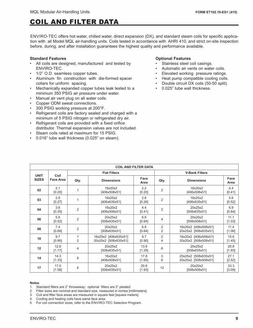
COIL AND FILTER DATA
ENVIRO-TEC offers hot water, chilled water, direct expansion (DX), and standard steam coils for specific applica-tion with all Model MQL air-handling units. Coils tested in accordance with AHRI 410, and strict on-site inspection before, during, and after installation guarantees the highest quality and performance available.
Standard Features • All coils are designed, manufactured and tested by
ENVIRO-TEC. • 1/2” O.D. seamless copper tubes.• Aluminum fin construction with die-formed spacer
collars for uniform spacing. • Mechanically expanded copper tubes leak tested to a
minimum 350 PSIG air pressure under water.• Manual air vent plug on all water coils. • Copper ODM sweat connections. • 300 PSIG working pressure at 200°F .• Refrigerant coils are factory sealed and charged with a
minimum of 5 PSIG nitrogen or refrigerated dry air.• Refrigerant coils are provided with a fixed orifice
distributor. Thermal expansion valves are not included.• Steam coils rated at maximum for 15 PSIG. • 0.016” tube wall thickness (0.025” on steam).
Optional Features • Stainless steel coil casings. • Automatic air vents on water coils.• Elevated working pressure ratings.• Heat pump compatible cooling coils.• Double circuit DX coils (50-50 split).• 0.025” tube wall thickness.
COIL AND FILTER DATA
UNIT SIZES
CoilFace Area
Flat Filters V-Bank Filters
Qty. Dimensions Face Area Qty. Dimensions Face
Area
02 2.1 [0.20] 1 16x20x2
[406x508x51]2.2
[0.20] 2 16x20x2 [406x508x51]
4.4 [0.41]
03 2.9 [0.27] 1 16x25x2
[406x635x51]2.8
[0.26] 2 16x25x2 [406x635x51]
5.6 [0.52]
04 3.8 [0.35] 2 16x20x2
[406x508x51]4.4
[0.41] 2 20x25x2 [508x635x51]
6.9 [0.64]
06 5.6 [0.52] 2 20x25x2
[508x635x51]6.9
[0.64] 4 20x20x2 [508x508x51]
11.1 [1.03]
08 7.4 [0.69] 2 20x25x2
[508x635x51]6.9
[0.64]2 2
16x20x2 [406x508x51] 20x25x2 [508x635x51]
11.4 [1.06]
10 9.7 [0.90]
1 2
16x25x2 [406x635x51] 20x25x2 [508x635x51]
9.7 [0.90]
2 4
16x20x2 [406x508x51] 20x20x2 [508x508x51]
15.6 [1.45]
12 12.6 [1.17] 4 20x25x2
[508x635x51]13.9 [1.29] 6 20x25x2
[508x635x51]20.8 [1.93]
14 14.3 [1.33] 8 16x20x2
[406x508x51]17.8 [1.65]
3 6
20x25x2 [508x635x51] 20x20x2 [508x508x51]
27.1 [2.52]
17 17.0 [1.58] 6 20x25x2
[508x635x51]20.8 [1.93] 12 20x20x2
[508x508x51]33.3 [3.09]
Notes: 1. Standard filters are 2” throwaway; optional filters are 2” pleated. 2. Filter sizes are nominal and standard size, measured in inches [millimeters]. 3. Coil and filter face areas are measured in square feet [square meters]. 4. Cooling and heating coils have same face area. 5. For coil connection sizes, refer to the ENVIRO-TEC Selection Program.
10 ENVIRO-TEC
MQL Modular Air-Handling Units FORM ET102.19-EG1 (415)
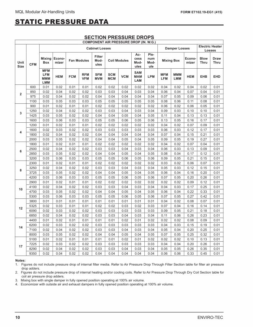
STATIC PRESSURE DATA
SECTION PRESSURE DROPSCOMPONENT AIR PRESSURE DROP (IN. W.G.)
Unit Size CFM
Cabinet Losses Damper Losses Electric Heater Losses
Mixing Box
Econo- mizer Fan Modules
Filter Mod-ules
Coil Modules
Ac-cess Mod-ules
Ple-num Mod-ule
Mixing Box Econo- mizer
Blow Thru
Draw Thru
MFM LFM MMM LMM
HEM FCM RFM VFM
SFM MVM
SCM MCM VCM
SAM MAM LAM
LPM MFM LFM
MMM LMM HEM EHB EHD
2
600 0.01 0.02 0.01 0.01 0.02 0.02 0.02 0.02 0.02 0.04 0.02 0.04 0.02 0.01850 0.02 0.04 0.02 0.02 0.03 0.03 0.04 0.03 0.04 0.06 0.04 0.07 0.04 0.01975 0.02 0.04 0.02 0.02 0.04 0.04 0.04 0.04 0.04 0.07 0.05 0.09 0.06 0.011100 0.03 0.05 0.03 0.03 0.05 0.05 0.05 0.05 0.05 0.08 0.06 0.11 0.08 0.01
3
900 0.01 0.02 0.01 0.01 0.02 0.02 0.02 0.02 0.02 0.06 0.02 0.06 0.05 0.011250 0.02 0.04 0.02 0.02 0.03 0.03 0.04 0.03 0.04 0.09 0.03 0.10 0.10 0.011425 0.03 0.05 0.02 0.02 0.04 0.04 0.05 0.04 0.05 0.11 0.04 0.13 0.13 0.011600 0.03 0.06 0.03 0.03 0.05 0.05 0.06 0.05 0.06 0.13 0.05 0.16 0.17 0.01
4
1200 0.01 0.02 0.01 0.01 0.02 0.02 0.02 0.02 0.02 0.04 0.02 0.07 0.09 0.011600 0.02 0.03 0.02 0.02 0.03 0.03 0.03 0.03 0.03 0.06 0.03 0.12 0.17 0.011800 0.02 0.04 0.02 0.02 0.04 0.04 0.04 0.04 0.04 0.07 0.04 0.15 0.21 0.012000 0.03 0.05 0.02 0.02 0.04 0.04 0.05 0.04 0.05 0.09 0.05 0.19 0.27 0.01
6
1800 0.01 0.02 0.01 0.01 0.02 0.02 0.02 0.02 0.02 0.04 0.02 0.07 0.04 0.012500 0.02 0.04 0.02 0.02 0.03 0.03 0.04 0.03 0.04 0.06 0.03 0.13 0.09 0.012850 0.03 0.05 0.02 0.02 0.04 0.04 0.05 0.04 0.05 0.08 0.04 0.17 0.12 0.013200 0.03 0.06 0.03 0.03 0.05 0.05 0.06 0.05 0.06 0.09 0.05 0.21 0.15 0.01
8
2300 0.01 0.02 0.01 0.01 0.02 0.02 0.02 0.02 0.02 0.03 0.02 0.06 0.07 0.013250 0.02 0.04 0.02 0.02 0.03 0.03 0.04 0.03 0.04 0.05 0.03 0.12 0.15 0.013725 0.03 0.05 0.02 0.02 0.04 0.04 0.05 0.04 0.05 0.06 0.04 0.16 0.20 0.014200 0.03 0.06 0.03 0.03 0.05 0.05 0.06 0.05 0.06 0.07 0.05 0.20 0.26 0.01
10
2900 0.01 0.02 0.01 0.01 0.02 0.02 0.02 0.02 0.02 0.02 0.02 0.09 0.12 0.014100 0.02 0.04 0.02 0.02 0.03 0.03 0.04 0.03 0.04 0.04 0.03 0.17 0.25 0.014700 0.03 0.05 0.02 0.02 0.04 0.04 0.05 0.04 0.05 0.06 0.04 0.22 0.33 0.015300 0.03 0.06 0.03 0.03 0.05 0.05 0.06 0.05 0.06 0.07 0.05 0.27 0.42 0.01
12
3800 0.01 0.01 0.01 0.01 0.01 0.01 0.01 0.01 0.01 0.04 0.02 0.08 0.07 0.015325 0.02 0.03 0.01 0.01 0.02 0.02 0.03 0.02 0.03 0.07 0.04 0.16 0.14 0.016090 0.02 0.03 0.02 0.02 0.03 0.03 0.03 0.03 0.03 0.09 0.05 0.21 0.18 0.016850 0.02 0.04 0.02 0.02 0.03 0.03 0.04 0.03 0.04 0.11 0.06 0.26 0.23 0.01
14
4400 0.01 0.02 0.01 0.01 0.01 0.01 0.02 0.01 0.02 0.02 0.02 0.08 0.09 0.016200 0.02 0.03 0.02 0.02 0.03 0.03 0.03 0.03 0.03 0.04 0.03 0.15 0.19 0.017100 0.02 0.04 0.02 0.02 0.03 0.03 0.04 0.03 0.04 0.05 0.04 0.20 0.25 0.018000 0.03 0.05 0.02 0.02 0.04 0.04 0.05 0.04 0.05 0.07 0.05 0.25 0.32 0.01
17
5100 0.01 0.02 0.01 0.01 0.01 0.01 0.02 0.01 0.02 0.02 0.02 0.10 0.13 0.017225 0.02 0.03 0.02 0.02 0.03 0.03 0.03 0.03 0.03 0.04 0.04 0.20 0.26 0.018290 0.02 0.04 0.02 0.02 0.03 0.03 0.04 0.03 0.04 0.05 0.05 0.26 0.35 0.019350 0.02 0.04 0.02 0.02 0.04 0.04 0.04 0.04 0.04 0.06 0.06 0.33 0.45 0.01
Notes:1. Figures do not include pressure drop of internal filter media. Refer to Air Pressure Drop Through Filter Section table for filter air pressure
drop adders.2. Figures do not include pressure drop of internal heating and/or cooling coils. Refer to Air Pressure Drop Through Dry Coil Section table for
coil air pressure drop adders.3. Mixing box with single damper in fully opened position operating at 100% air volume.4. Economizer with outside air and exhaust dampers in fully opened position operating at 100% air volume.
ENVIRO-TEC 11
MQL Modular Air-Handling Units FORM ET102.19-EG1 (415)
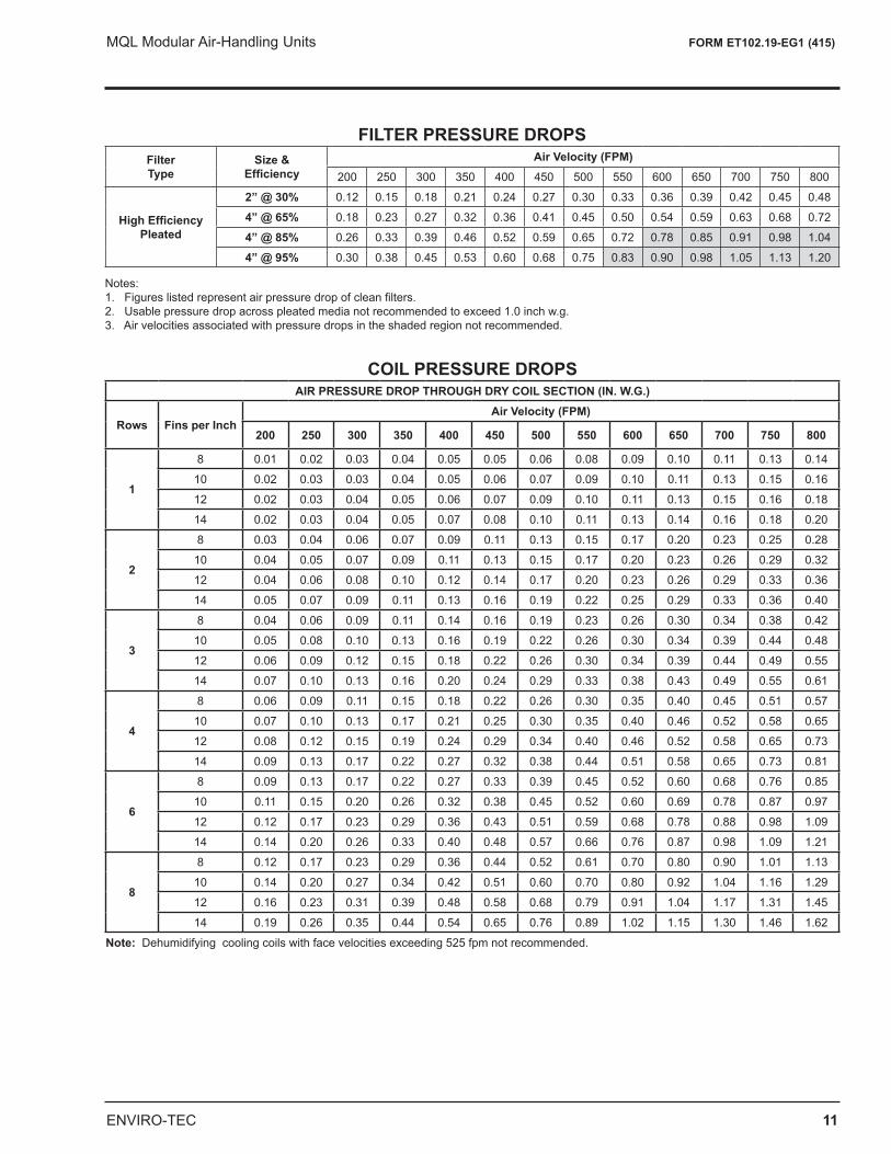
FILTER PRESSURE DROPSFilter Type
Size & Efficiency
Air Velocity (FPM)200 250 300 350 400 450 500 550 600 650 700 750 800
High Efficiency Pleated
2” @ 30% 0.12 0.15 0.18 0.21 0.24 0.27 0.30 0.33 0.36 0.39 0.42 0.45 0.48
4” @ 65% 0.18 0.23 0.27 0.32 0.36 0.41 0.45 0.50 0.54 0.59 0.63 0.68 0.72
4” @ 85% 0.26 0.33 0.39 0.46 0.52 0.59 0.65 0.72 0.78 0.85 0.91 0.98 1.04
4” @ 95% 0.30 0.38 0.45 0.53 0.60 0.68 0.75 0.83 0.90 0.98 1.05 1.13 1.20
Notes:1. Figures listed represent air pressure drop of clean filters.2. Usable pressure drop across pleated media not recommended to exceed 1.0 inch w.g.3. Air velocities associated with pressure drops in the shaded region not recommended.
COIL PRESSURE DROPSAIR PRESSURE DROP THROUGH DRY COIL SECTION (IN. W.G.)
Rows Fins per InchAir Velocity (FPM)
200 250 300 350 400 450 500 550 600 650 700 750 800
1
8 0.01 0.02 0.03 0.04 0.05 0.05 0.06 0.08 0.09 0.10 0.11 0.13 0.14
10 0.02 0.03 0.03 0.04 0.05 0.06 0.07 0.09 0.10 0.11 0.13 0.15 0.16
12 0.02 0.03 0.04 0.05 0.06 0.07 0.09 0.10 0.11 0.13 0.15 0.16 0.18
14 0.02 0.03 0.04 0.05 0.07 0.08 0.10 0.11 0.13 0.14 0.16 0.18 0.20
2
8 0.03 0.04 0.06 0.07 0.09 0.11 0.13 0.15 0.17 0.20 0.23 0.25 0.28
10 0.04 0.05 0.07 0.09 0.11 0.13 0.15 0.17 0.20 0.23 0.26 0.29 0.32
12 0.04 0.06 0.08 0.10 0.12 0.14 0.17 0.20 0.23 0.26 0.29 0.33 0.36
14 0.05 0.07 0.09 0.11 0.13 0.16 0.19 0.22 0.25 0.29 0.33 0.36 0.40
3
8 0.04 0.06 0.09 0.11 0.14 0.16 0.19 0.23 0.26 0.30 0.34 0.38 0.42
10 0.05 0.08 0.10 0.13 0.16 0.19 0.22 0.26 0.30 0.34 0.39 0.44 0.48
12 0.06 0.09 0.12 0.15 0.18 0.22 0.26 0.30 0.34 0.39 0.44 0.49 0.55
14 0.07 0.10 0.13 0.16 0.20 0.24 0.29 0.33 0.38 0.43 0.49 0.55 0.61
4
8 0.06 0.09 0.11 0.15 0.18 0.22 0.26 0.30 0.35 0.40 0.45 0.51 0.57
10 0.07 0.10 0.13 0.17 0.21 0.25 0.30 0.35 0.40 0.46 0.52 0.58 0.65
12 0.08 0.12 0.15 0.19 0.24 0.29 0.34 0.40 0.46 0.52 0.58 0.65 0.73
14 0.09 0.13 0.17 0.22 0.27 0.32 0.38 0.44 0.51 0.58 0.65 0.73 0.81
6
8 0.09 0.13 0.17 0.22 0.27 0.33 0.39 0.45 0.52 0.60 0.68 0.76 0.85
10 0.11 0.15 0.20 0.26 0.32 0.38 0.45 0.52 0.60 0.69 0.78 0.87 0.97
12 0.12 0.17 0.23 0.29 0.36 0.43 0.51 0.59 0.68 0.78 0.88 0.98 1.09
14 0.14 0.20 0.26 0.33 0.40 0.48 0.57 0.66 0.76 0.87 0.98 1.09 1.21
8
8 0.12 0.17 0.23 0.29 0.36 0.44 0.52 0.61 0.70 0.80 0.90 1.01 1.13
10 0.14 0.20 0.27 0.34 0.42 0.51 0.60 0.70 0.80 0.92 1.04 1.16 1.29
12 0.16 0.23 0.31 0.39 0.48 0.58 0.68 0.79 0.91 1.04 1.17 1.31 1.45
14 0.19 0.26 0.35 0.44 0.54 0.65 0.76 0.89 1.02 1.15 1.30 1.46 1.62
Note: Dehumidifying cooling coils with face velocities exceeding 525 fpm not recommended.
12 ENVIRO-TEC
MQL Modular Air-Handling Units FORM ET102.19-EG1 (415)
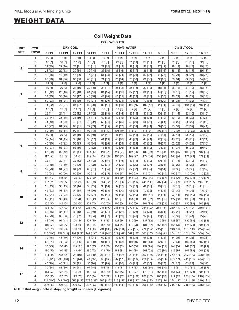
WEIGHT DATA
Coil Weight DataCOIL WEIGHTS
UNIT SIZE
COIL ROWS
DRY COIL 100% WATER 40% GLYCOL8 FPI 10 FPI 12 FPI 14 FPI 8 FPI 10 FPI 12 FPI 14 FPI 8 FPI 10 FPI 12 FPI 14 FPI
2
1 10 [5] 11 [5] 11 [5] 11 [5] 12 [5] 12 [5] 13 [6] 13 [6] 12 [5] 12 [5] 13 [6] 13 [6]2 16 [7] 16 [7] 17 [8] 18 [8] 19 [9] 20 [9] 21 [10] 21 [10] 20 [9] 20 [9] 21 [10] 22 [10]3 21 [10] 22 [10] 23 [11] 24 [11] 27 [12] 28 [13] 29 [13] 30 [14] 27 [12] 28 [13] 29 [13] 30 [14]4 28 [13] 29 [13] 30 [14] 32 [14] 35 [16] 36 [16] 37 [17] 39 [18] 35 [16] 36 [16] 38 [17] 39 [18]6 40 [18] 42 [19] 44 [20] 46 [21] 51 [23] 53 [24] 55 [25] 57 [26] 51 [23] 53 [24] 55 [25] 58 [26]8 57 [26] 61 [28] 65 [30] 69 [31] 71 [32] 75 [34] 79 [36] 83 [38] 72 [33] 76 [34] 80 [36] 84 [38]
3
1 13 [6] 13 [6] 13 [6] 14 [6] 15 [7] 16 [7] 16 [7] 17 [8] 15 [7] 16 [7] 16 [7] 17 [8]2 19 [9] 20 [9] 21 [10] 22 [10] 24 [11] 25 [12] 26 [12] 27 [12] 25 [11] 26 [12] 27 [12] 28 [13]3 26 [12] 28 [13] 29 [13] 31 [14] 34 [15] 35 [16] 37 [17] 38 [17] 34 [15] 36 [16] 37 [17] 39 [17]4 34 [15] 36 [16] 38 [17] 40 [18] 44 [20] 46 [21] 48 [22] 50 [23] 44 [20] 46 [21] 48 [22] 50 [23]6 50 [23] 53 [24] 56 [25] 59 [27] 64 [29] 67 [31] 70 [32] 73 [33] 65 [20] 68 [31] 71 [32] 74 [34]8 71 [32] 76 [34] 81 [37] 86 [39] 89 [41] 95 [43] 100 [45] 105 [47] 91 [41] 96 [43] 101 [46] 106 [48]
4
1 15 [7] 15 [7] 16 [7] 17 [8] 18 [8] 18 [8] 19 [9] 20 [9] 18 [8] 19 [9] 19 [9] 20 [9]2 23 [11] 24 [11] 26 [12] 27 [12] 29 [13] 30 [14] 32 [15] 33 [15] 30 [13] 31 [14] 32 [15] 33 [15]3 32 [14] 33 [15] 35 [16] 37 [17] 40 [18] 42 [19] 44 [20] 46 [21] 41 [19] 43 [19] 45 [20] 47 [21]4 41 [19] 44 [20] 46 [21] 49 [22] 53 [24] 55 [25] 58 [26] 60 [27] 54 [24] 56 [25] 59 [27] 61 [28]6 60 [27] 64 [29] 68 [31] 72 [33] 78 [35] 82 [37] 86 [39] 89 [41] 79 [36] 83 [38] 87 [39] 90 [41]8 80 [36] 85 [38] 90 [41] 95 [43] 103 [47] 108 [49] 113 [51] 118 [54] 105 [47] 110 [50] 115 [52] 120 [54]
6
1 19 [9] 20 [9] 21 [10] 22 [10] 24 [11] 25 [11] 26 [12] 27 [12] 24 [11] 25 [11] 26 [12] 27 [12]2 32 [14] 34 [15] 36 [16] 38 [17] 41 [19] 43 [20] 45 [20] 47 [21] 42 [19] 43 [20] 45 [20] 47 [21]3 45 [20] 48 [22] 50 [23] 53 [24] 58 [26] 61 [28] 64 [29] 67 [30] 59 [27] 62 [28] 65 [29] 67 [30]4 59 [27] 62 [28] 66 [30] 70 [32] 76 [35] 80 [36] 84 [38] 88 [40] 77 [35] 81 [37] 85 [39] 89 [40]6 87 [39] 92 [42] 98 [44] 104 [47] 113 [51] 119 [54] 124 [56] 130 [59] 115 [52] 120 [55] 126 [57] 132 [60]8 117 [53] 125 [57] 133 [61] 142 [64] 152 [69] 160 [73] 169 [77] 177 [80] 155 [70] 163 [74] 171 [78] 179 [81]
8
1 23 [11] 25 [11] 26 [12] 27 [12] 30 [14] 31 [14] 32 [15] 33 [15] 30 [14] 31 [14] 32 [15] 34 [15]2 40 [18] 43 [19] 45 [20] 48 [22] 52 [24] 54 [25] 57 [26] 59 [27] 53 [24] 55 [25] 58 [26] 60 [27]3 57 [26] 61 [27] 64 [29] 68 [31] 75 [34] 78 [36] 82 [37] 86 [39] 76 [34] 79 [36] 83 [38] 87 [39]4 75 [34] 80 [36] 85 [38] 90 [41] 98 [45] 103 [47] 108 [49] 113 [51] 100 [45] 105 [47] 110 [50] 115 [52]6 111 [50] 118 [54] 126 [57] 133 [60] 146 [66] 153 [69] 161 [73] 168 [76] 148 [67] 155 [70] 163 [74] 170 [77]8 157 [71] 169 [77] 182 [83] 195 [88] 204 [92] 216 [98] 229 [104] 241 [110] 207 [94] 219 [99] 232 [105] 245 [111]
10
1 28 [13] 30 [13] 31 [14] 33 [15] 36 [16] 37 [17] 39 [18] 40 [18] 36 [16] 38 [17] 39 [18] 41 [18]2 48 [22] 51 [23] 54 [25] 57 [26] 63 [28] 66 [30] 69 [31] 72 [33] 64 [29] 67 [30] 70 [32] 73 [33]3 68 [31] 73 [33] 77 [35] 82 [37] 90 [41] 95 [43] 99 [45] 104 [47] 91 [41] 96 [44] 101 [46] 106 [48]4 89 [41] 96 [43] 102 [46] 108 [49] 119 [54] 125 [57] 131 [60] 138 [62] 120 [55] 127 [58] 133 [60] 139 [63]6 133 [60] 142 [64] 152 [69] 161 [73] 176 [80] 186 [84] 195 [88] 204 [93] 179 [81] 188 [85] 198 [90] 207 [94]8 183 [83] 197 [90] 212 [96] 226 [103] 241 [109] 255 [116] 270 [122] 284 [129] 244 [111] 259 [117] 273 [124] 288 [131]
12
1 35 [16] 37 [17] 39 [18] 42 [19] 45 [21] 48 [22] 50 [23] 52 [24] 46 [21] 48 [22] 50 [23] 52 [24]2 62 [28] 66 [30] 70 [32] 74 [34] 81 [37] 86 [39] 90 [41] 94 [43] 83 [38] 87 [39] 91 [41] 95 [43]3 88 [40] 94 [43] 101 [46] 107 [49] 118 [53] 124 [56] 130 [59] 137 [62] 119 [54] 126 [57] 132 [60] 139 [63]4 116 [53] 125 [57] 133 [60] 142 [64] 155 [70] 164 [74] 172 [78] 181 [82] 158 [72] 166 [75] 175 [79] 184 [83]6 173 [78] 186 [84] 199 [90] 211 [96] 231 [105] 244 [111] 257 [117] 270 [122] 235 [107] 248 [112] 261 [118] 274 [124]8 233 [106] 251 [114] 269 [122] 287 [130] 311 [141] 329 [149] 347 [157] 365 [165] 316 [143] 334 [151] 352 [160] 370 [168]
14
1 39 [18] 41 [19] 44 [20] 46 [21] 50 [23] 53 [24] 55 [25] 58 [26] 51 [23] 54 [24] 56 [25] 58 [26]2 69 [31] 74 [33] 78 [36] 83 [38] 91 [41] 96 [43] 101 [46] 106 [48] 92 [42] 97 [44] 102 [46] 107 [49]3 98 [45] 106 [48] 113 [51] 120 [55] 132 [60] 139 [63] 146 [66] 154 [70] 134 [61] 141 [64] 149 [67] 156 [71]4 130 [59] 140 [63] 149 [68] 159 [72] 174 [79] 184 [83] 194 [88] 203 [92] 177 [80] 187 [85] 197 [89] 206 [94]6 194 [88] 208 [94] 223 [101] 237 [108] 260 [118] 274 [124] 289 [131] 303 [138] 264 [120] 279 [126] 293 [133] 308 [140]8 272 [123] 295 [134] 318 [144] 341 [155] 359 [163] 382 [173] 405 [184] 428 [194] 365 [166] 388 [176] 411 [186] 434 [197]
17
1 45 [20] 48 [22] 51 [23] 53 [24] 58 [26] 61 [28] 64 [29] 67 [30] 59 [27] 62 [28] 65 [29] 68 [31]2 79 [36] 85 [39] 91 [41] 97 [44] 106 [48] 112 [51] 117 [53] 123 [56] 108 [49] 113 [51] 119 [54] 125 [57]3 114 [52] 122 [56] 131 [59] 140 [63] 153 [69] 162 [73] 170 [77] 179 [81] 155 [71] 164 [74] 173 [78] 181 [82]4 150 [68] 162 [73] 173 [79] 185 [84] 203 [92] 214 [97] 226 [102] 237 [108] 206 [93] 217 [99] 229 [104] 240 [109]6 224 [102] 241 [109] 259 [117] 276 [125] 302 [137] 319 [145] 336 [153] 354 [160] 307 [139] 324 [147] 341 [155] 359 [163]8 206 [93] 206 [93] 206 [93] 206 [93] 309 [140] 309 [140] 309 [140] 309 [140] 315 [143] 315 [143] 315 [143] 315 [143]
NOTE: Unit weight data is shipping weight in pounds [kilograms].
ENVIRO-TEC 13
MQL Modular Air-Handling Units FORM ET102.19-EG1 (415)
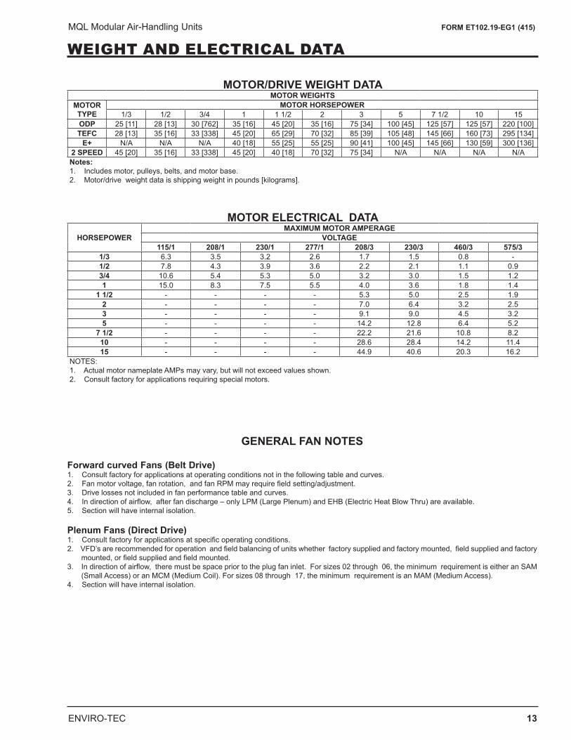
WEIGHT AND ELECTRICAL DATA
MOTOR/DRIVE WEIGHT DATAMOTOR WEIGHTS
MOTOR TYPE
MOTOR HORSEPOWER1/3 1/2 3/4 1 1 1/2 2 3 5 7 1/2 10 15
ODP 25 [11] 28 [13] 30 [762] 35 [16] 45 [20] 35 [16] 75 [34] 100 [45] 125 [57] 125 [57] 220 [100]TEFC 28 [13] 35 [16] 33 [338] 45 [20] 65 [29] 70 [32] 85 [39] 105 [48] 145 [66] 160 [73] 295 [134]
E+ N/A N/A N/A 40 [18] 55 [25] 55 [25] 90 [41] 100 [45] 145 [66] 130 [59] 300 [136]2 SPEED 45 [20] 35 [16] 33 [338] 45 [20] 40 [18] 70 [32] 75 [34] N/A N/A N/A N/ANotes:1. Includes motor, pulleys, belts, and motor base.2. Motor/drive weight data is shipping weight in pounds [kilograms].
MOTOR ELECTRICAL DATAHORSEPOWER
MAXIMUM MOTOR AMPERAGEVOLTAGE
115/1 208/1 230/1 277/1 208/3 230/3 460/3 575/31/3 6.3 3.5 3.2 2.6 1.7 1.5 0.8 -1/2 7.8 4.3 3.9 3.6 2.2 2.1 1.1 0.93/4 10.6 5.4 5.3 5.0 3.2 3.0 1.5 1.21 15.0 8.3 7.5 5.5 4.0 3.6 1.8 1.4
1 1/2 - - - - 5.3 5.0 2.5 1.92 - - - - 7.0 6.4 3.2 2.53 - - - - 9.1 9.0 4.5 3.25 - - - - 14.2 12.8 6.4 5.2
7 1/2 - - - - 22.2 21.6 10.8 8.210 - - - - 28.6 28.4 14.2 11.415 - - - - 44.9 40.6 20.3 16.2
NOTES:1. Actual motor nameplate AMPs may vary, but will not exceed values shown.2. Consult factory for applications requiring special motors.
Forward curved Fans (Belt Drive) 1. Consult factory for applications at operating conditions not in the following table and curves.2. Fan motor voltage, fan rotation, and fan RPM may require field setting/adjustment. 3. Drive losses not included in fan performance table and curves. 4. In direction of airflow, after fan discharge – only LPM (Large Plenum) and EHB (Electric Heat Blow Thru) are available.5. Section will have internal isolation. Plenum Fans (Direct Drive) 1. Consult factory for applications at specific operating conditions.2. VFD’s are recommended for operation and field balancing of units whether factory supplied and factory mounted, field supplied and factory
mounted, or field supplied and field mounted. 3. In direction of airflow, there must be space prior to the plug fan inlet. For sizes 02 through 06, the minimum requirement is either an SAM
(Small Access) or an MCM (Medium Coil). For sizes 08 through 17, the minimum requirement is an MAM (Medium Access).4. Section will have internal isolation.
GENERAL FAN NOTES
14 ENVIRO-TEC
MQL Modular Air-Handling Units FORM ET102.19-EG1 (415)
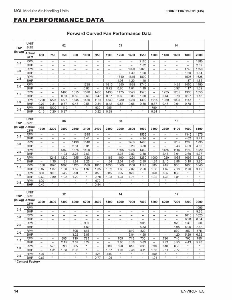
FAN PERFORMANCE DATA
Forward Curved Fan Performance Data
TSP(in-wg)
UNIT SIZE 02 03 04
Actual CFM 650 750 850 950 1050 950 1100 1250 1400 1550 1200 1400 1600 1800 2000
3.5 RPM – – – – – – – – – 2160 – – – – 1880BHP – – – – – – – – – 1.82 – – – – 2.09
3.0 RPM – – – – – – – – 1990 2025 – – – 1740 1750BHP – – – – – – – – 1.39 1.60 – – – 1.60 1.84
2.5 RPM – – – – – – – 1810 1845 1890 – – – 1595 1625BHP – – – – – – – 1.03 1.20 1.40 – – – 1.37 1.62
2.0 RPM – – – – 1725 – 1615 1650 1695 1740 – – 1425 1455 1490BHP – – – – 0.86 – 0.72 0.86 1.01 1.19 – – 0.97 1.17 1.39
1.5 RPM – – 1485 1515 1570 1400 1435 1475 1525 1575 – 1235 1265 1305 1355BHP – – 0.53 0.59 0.69 0.47 0.57 0.69 0.83 1.00 – 0.64 0.79 0.97 1.18
1.0 RPM 1200 1225 1275 1345 1430 1185 1230 1280 1330 1390 1015 1050 1095 1145 *BHP 0.27 0.31 0.37 0.45 0.56 0.34 0.42 0.53 0.66 0.80 0.37 0.48 0.61 0.78 *
0.5 RPM 935 1020 1110 * * 930 985 * * * 790 * * * *BHP 0.15 0.20 0.27 * * 0.22 0.29 * * * 0.24 * * * *
TSP(in-wg)
UNIT SIZE 06 08 10
Actual CFM 1900 2200 2500 2800 3100 2400 2800 3200 3600 4000 3100 3600 4100 4600 5100
3.5 RPM – – – – 1615 – – – – 1555 – – – 1345 1375BHP – – – – 3.41 – – – – 4.24 – – – 4.62 5.41
3.0 RPM – – – 1490 1510 – – – 1435 1460 – – 1235 1260 1295BHP – – – 2.61 3.01 – – – 3.23 3.80 – – 3.43 4.09 4.80
2.5 RPM – – 1360 1375 1400 – – 1305 1330 1360 – 1125 1145 1180 1220BHP – – 1.93 2.25 2.63 – – 2.36 2.83 3.38 – 2.46 3.01 3.60 4.37
2.0 RPM – 1215 1230 1255 1280 – 1165 1190 1220 1250 1000 1020 1055 1095 1135BHP – 1.35 1.61 1.91 2.25 – 1.64 2.01 2.45 2.95 1.65 2.10 2.56 3.18 3.90
1.5 RPM 1050 1070 1090 1125 1160 1010 1030 1060 1100 1140 885 915 955 1000 1045BHP 0.87 1.07 1.30 1.59 1.92 1.05 1.32 1.66 2.07 2.56 1.36 1.69 2.18 2.76 3.42
1.0 RPM 880 905 945 990 * 850 885 925 970 * 760 805 850 * *BHP 0.63 0.80 1.02 1.29 * 0.78 1.03 1.34 1.71 * 1.02 1.38 1.81 * *
0.5 RPM 690 * * * * 670 * * * * * * * * *BHP 0.42 * * * * 0.54 * * * * * * * * *
TSP(in-wg)
UNIT SIZE 12 14 17
Actual CFM 3900 4600 5300 6000 6700 4600 5400 6200 7000 7800 5200 6200 7200 8200 9200
3.5 RPM – – – – – – – – – – – – – – 1095BHP – – – – – – – – – – – – – – 9.25
3.0 RPM – – – – – – – – – – – – – 1010 1025BHP – – – – – – – – – – – – – 6.98 8.34
2.5 RPM – – – – 900 – – – – 905 – – 920 930 950BHP – – – – 4.50 – – – – 5.33 – – 5.05 6.06 7.42
2.0 RPM – – – 805 815 – – – 810 820 – – 830 850 875BHP – – – 3.22 3.88 – – – 3.84 4.58 – – 4.20 5.29 6.52
1.5 RPM – – 695 710 725 – – 705 715 730 – 720 740 760 785BHP – – 2.15 2.67 3.24 – – 2.60 3.16 3.83 – 2.71 3.53 4.43 5.48
1.0 RPM – 575 590 605 * – 580 590 610 635 590 610 635 * *BHP – 1.31 1.68 2.05 * – 1.57 1.97 2.48 3.11 1.55 2.11 2.77 * *
0.5 RPM 420 * * * * 425 445 * * * 450 * * * *BHP 0.63 * * * * 0.77 1.05 * * * 1.01 * * * *
* Contact Factory
ENVIRO-TEC 15
MQL Modular Air-Handling Units FORM ET102.19-EG1 (415)
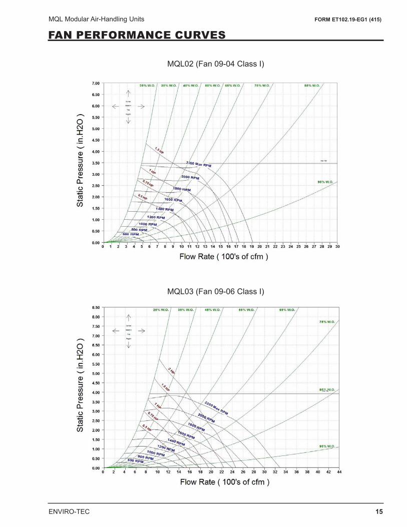
FAN PERFORMANCE CURVES
MQL02 (Fan 09-04 Class I)
MQL03 (Fan 09-06 Class I)
16 ENVIRO-TEC
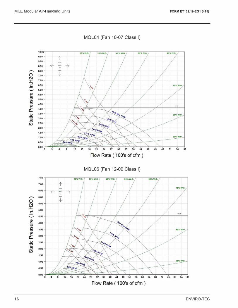
MQL Modular Air-Handling Units FORM ET102.19-EG1 (415)
MQL06 (Fan 12-09 Class I)
MQL04 (Fan 10-07 Class I)
ENVIRO-TEC 17
MQL Modular Air-Handling Units FORM ET102.19-EG1 (415)
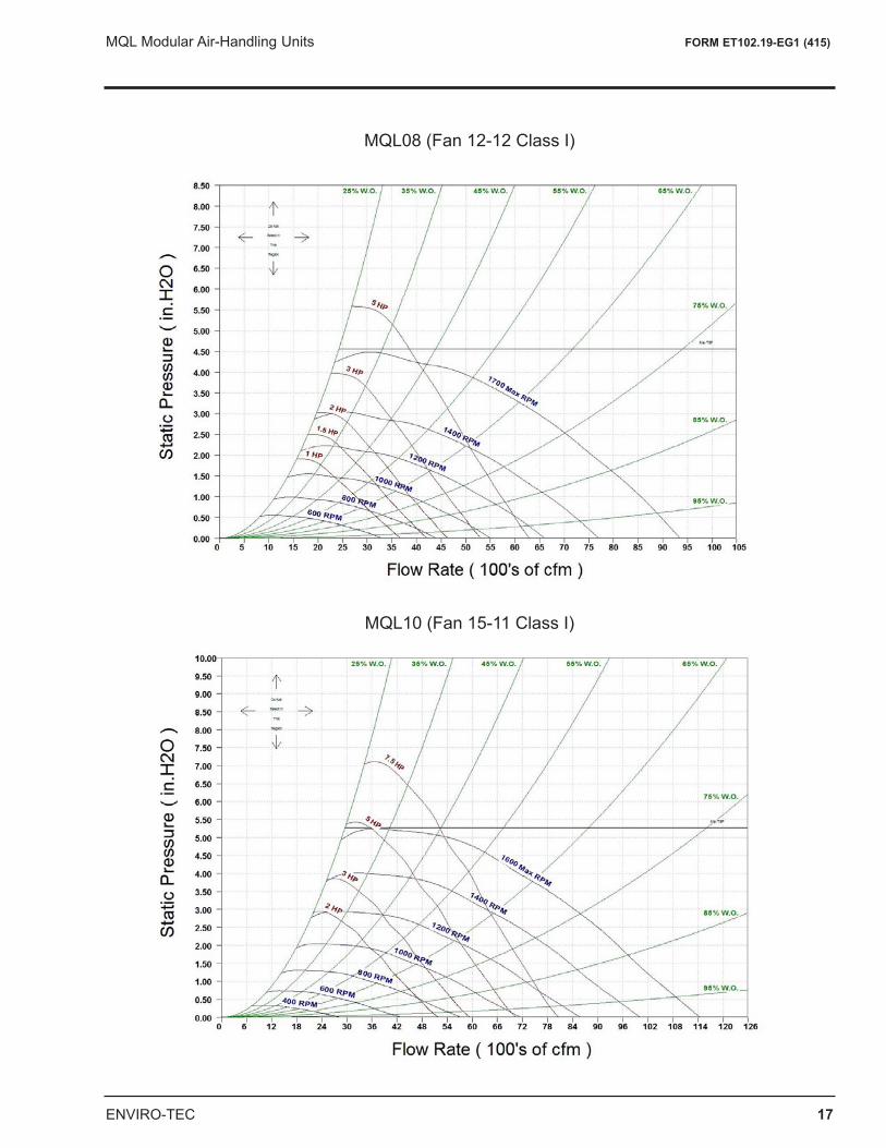
MQL08 (Fan 12-12 Class I)
MQL10 (Fan 15-11 Class I)
18 ENVIRO-TEC
MQL Modular Air-Handling Units FORM ET102.19-EG1 (415)
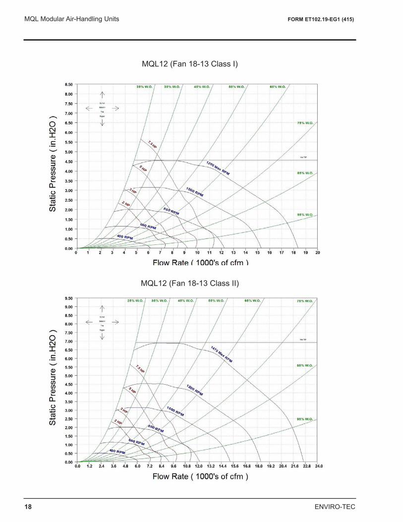
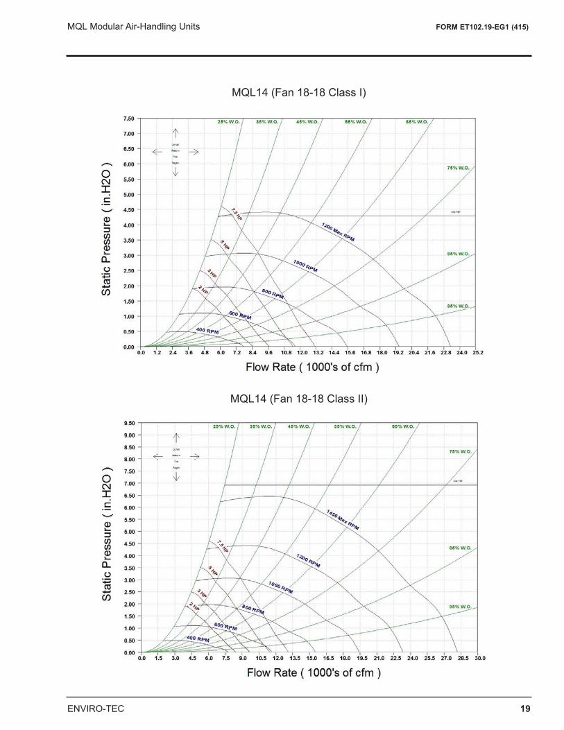
MQL12 (Fan 18-13 Class II)
MQL12 (Fan 18-13 Class I)
ENVIRO-TEC 19
MQL Modular Air-Handling Units FORM ET102.19-EG1 (415)
MQL14 (Fan 18-18 Class II)
MQL14 (Fan 18-18 Class I)
20 ENVIRO-TEC
MQL Modular Air-Handling Units FORM ET102.19-EG1 (415)
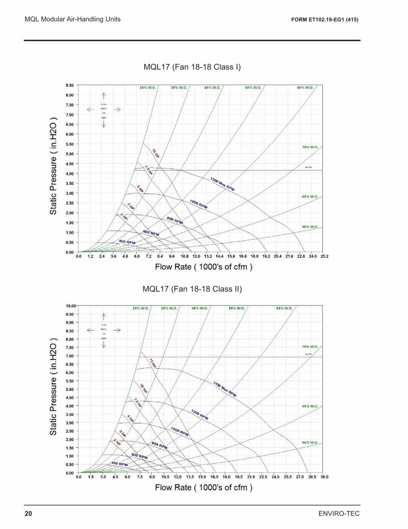
MQL17 (Fan 18-18 Class I)
MQL17 (Fan 18-18 Class II)
ENVIRO-TEC 21
MQL Modular Air-Handling Units FORM ET102.19-EG1 (415)
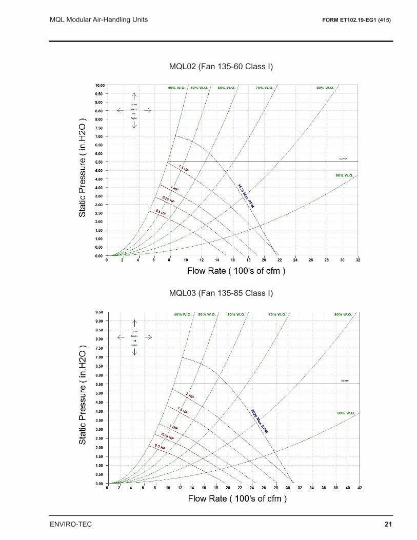
MQL02 (Fan 135-60 Class I)
MQL03 (Fan 135-85 Class I)
22 ENVIRO-TEC
MQL Modular Air-Handling Units FORM ET102.19-EG1 (415)
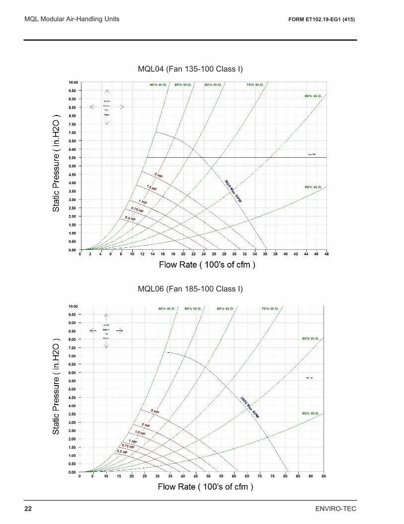
MQL04 (Fan 135-100 Class I)
MQL06 (Fan 185-100 Class I)
ENVIRO-TEC 23
MQL Modular Air-Handling Units FORM ET102.19-EG1 (415)
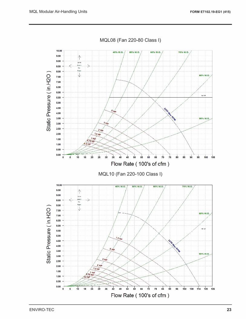
MQL08 (Fan 220-80 Class I)
MQL10 (Fan 220-100 Class I)
24 ENVIRO-TEC
MQL Modular Air-Handling Units FORM ET102.19-EG1 (415)
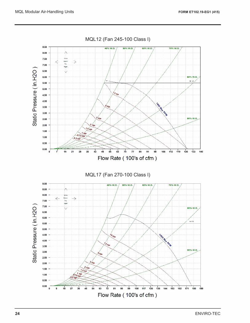
MQL12 (Fan 245-100 Class I)
MQL17 (Fan 270-100 Class I)
ENVIRO-TEC 25
MQL Modular Air-Handling Units FORM ET102.19-EG1 (415)
GUIDE SPECIFICATIONS
Air-Handling Unit
HVAC Guide Specifications - Section 15XXX Size Range: 600 – 10,000 CFMENVIRO-TEC Model Number: MQL
Part 1 — General1.01 SYSTEM DESCRIPTION
A. Indoor mounted air-handling unit designed to provide air to a conditioned space as required to meet speci-fied performance requirements for ventilation, heating, cooling, filtration and air distribution. Unit shall be assembled for draw thru application and shall be arranged to discharge conditioned air horizontally or verti-cally as shown on the contract drawings.
B. Unit with a direct-expansion cooling coil shall have the capability to be used in a refrigerant circuit in conjunc-tion with a field supplied and matched air-cooled condensing unit.
1.02 QUALITY ASSURANCE
A. Coils shall be tested in accordance with AHRI 410 “Standard for Forced-Circulation Air-Cooling and Air-Heating Coils”.
B. Direct expansion coils shall be designed and tested in accordance with ANSI/ASHRAE 15 “Safety Code for Refrigeration Systems”.
C. Insulation and insulation adhesive shall comply with NFPA 90A and 90B requirements for flame spread and smoke generation.
D. Unit shall be constructed in accordance with UL 1995 standards, comply with NEMA standards and shall carry the cETL label, display certification symbol on units of certified models. Installation of ancillary electri-cal components shall comply with NEC.
1.03 DELIVERY, STORAGE AND HANDLING Unit shall be stored and handled in accordance with the unit manufacturer’s instructions.
Part 2 — Products2.01 EQUIPMENT
A. General: Factory assembled air-handling unit that is modular in design and construction. Unit may consist of a fan and coil section with factory-installed chilled water or direct expansion coil, preheat or reheat coil, heating coil section, filter section, combination filter/mixing box (flat or V-bank arrangement), economizer, or access section(s) as indicated on the equipment schedules.
B. Unit Cabinet:
1. Unit panels shall be constructed of G60 galvanized steel and shall be capable of withstanding 125-hour salt spray test per ASTM Standard 117. All casing panels shall be removable for easy access to the unit. All panels shall be gasketed to ensure a tight seal.
2. Double wall unit panels (includes corner posts, mullions and access doors) shall be 1-in. nominal thick-ness using 1.5-lbs/ft3 fiberglass insulation between galvanized steel panels.
3. Single wall unit panels shall be 1-in. nominal thickness using matt-faced fiberglass insulation with a nominal density of not less than 1.5-lbs/ft3.
4. Insulation shall be secured to casing with water based adhesive and weld pins where necessary, cor-responding to 25/50-flame spread/smoke developed.
5. Condensate drain pans shall be sloped to prevent standing water and shall be constructed of 18 gauge G60 galvanized steel or stainless steel; they shall have a galvanized steel or stainless steel male pipe threaded drain connection.
26 ENVIRO-TEC
MQL Modular Air-Handling Units FORM ET102.19-EG1 (415)
C. Fan Section:
1. Fan sections shall be constructed of G60 steel and shall have a formed channel base for integral mount-ing of fan, motor, and casing panels. Fan housing, wheel, shaft, and bearings shall be rigidly secured to the base unit.
2. Fan decks shall be internally spring isolated (one-inch deflection) with the fan outlet connection to be made using canvas duct.
3. Each unit shall have one fan wheel and housing only.
4. Fan wheels shall be designed for continuous operation at the maximum rated fan speed and motor horsepower. Fan wheels and shafts shall be selected to operate at least 25% below the first critical speed, and shall be statically and dynamically balanced as an assembly.
5. Fan shafts shall be solid steel, turned, ground and polished.
6. Fan bearings shall be a self-aligning, non-regreasable ball bearing type selected for an average life (L50) of 100,000 hours at design operation conditions, per ANSI Code B3.15.
7. Fan motor shall be mounted within the fan section casing. Motor shall be NEMA Design B with sizes and electrical characteristics as shown on the equipment schedule.
8. Fan drive shall be designed for a minimum of 1.15 service factor and shall be factory mounted and aligned. Belt drive package shall be variable-pitch type (constant volume) or fixed-pitch type (variable volume).
D. Coil Sections:
1. All coils shall have aluminum plate fins mechanically bonded to 1/2-in. OD seamless copper tubes by mechanical expansion. Coils shall be factory leak tested at 350-psig air pressure under water. Copper tubes shall be either 0.016” or 0.025” copper tube wall thickness. Coils shall have G60 galvanized steel or stainless steel casings with copper headers and sweat connections.
2. Chilled water coils shall have a working pressure of 300 psig at 200° F. No turbulence-promoting devic-es will be permitted inside the tubes. Headers shall have vent connections.
3. Direct-expansion coils shall be provided with pressure-type brass distributors with solder-type connec-tions. Coils shall be designed and tested in accordance with ANSI/ASHRAE 15.
4. Hot water coils shall have a working pressure of 300 psig at 200° F. No turbulence-promoting devices will be permitted inside the tubes. Headers shall have vent connections.
5. Steam distributing coils (standard single tube type) shall have a maximum working pressure of 15 psig at ambient temperatures above 35° F. Tube wall thickness shall be 0.025” as standard.
6. Electric heat coils for use in blower coil units shall be open coil type, nichrome wire resistance elements, insulated by floating ceramic bushings. Thermal cutouts for primary and secondary over-temperature protection shall be provided to meet UL and NEC requirements. Maximum element watt density shall be 55-watts/sq inch. The manufacturer shall furnish an integral control box. It shall contain primary and secondary control thermal cutouts, relays, airflow switch, and fused control transformer.
E. Filter Sections:
1. Each filter section shall be designed and constructed to house the specific type of filter specified on the equipment schedule.
2. Flat filter sections shall accept 2-in. 30% (MERV-6) pleated filters of standard sizes. Sections shall include side access slide rails. Flat filter section shall be arranged with minimum depth in direction of airflow.
3. Angle filter section shall accept 2-in. 30% (MERV-6) pleated filters of standard sizes arranged in horizon-tal V formation. Sections shall include side access slide rails.
ENVIRO-TEC 27
MQL Modular Air-Handling Units FORM ET102.19-EG1 (415)
F. Damper Sections:
1. Mixing boxes, filter mixing boxes and economizers shall have parallel blade, interconnecting dampers. Damper blades shall have parallel bends for stiffness and shall be mechanically fastened to steel rods rotating in brass bushings and mounted in rigid galvanized steel frames. Dampers shall be sectionalized to limit blade width, minimize blade warpage, and ensure tight closure.
2. All dampers for mixing boxes and filter mixing boxes shall be rated with a leakage rate not to exceed 5% of air quantity calculated at 2000 fpm velocity though damper and 4.0-in.wg. pressure difference. Damper blades shall be gasketed and stainless steel perimeter-sealing strips shall be provided. Damper linkage shall be provided and installed with all mixing boxes.
G. Access Sections:
1. Access sections shall be installed where indicated on the drawings and shall be as specified on the equipment schedule.
2. Access sections shall have removable access panels.
H. Special Features
The following unit options shall be available.
1. Fan Section:
a. Variable frequency drives.
b. Motor starters – contactor with overload for three phase and contactor for single phase.
c. High-efficiency motors (inverter-duty).
d. Totally enclosed fan cooled (TEFC) motors (inverter-duty).
e. Two-speed motors.
f. Direct drive plenum fans with internal isolation.
g. Class II forward curved fans with regreasable pillow block bearings.
h. Exhaust or return fans for use with economizer sections.
2. Coil Section:
a. Chilled water coil with copper plate fins and/or stainless steel casing.
b. Direct-expansion coil with copper plate fins and/or stainless steel casing.
c. Hot water coil with copper plate fins and/or stainless steel casing.
d. Steam distributing coil with copper plate fins and/or stainless steel casing.
3. Filtration:
a. 4” pleated filter type (standard size), 60-65% efficiency (MERV-11)
b. 4” pleated filter type (standard size), 80-85% efficiency (MERV-13)
c. 4” pleated filter type (standard size), 90-95% efficiency (MERV-14)
4. Access Doors: Hinged (lift-off type) doors with quick-action latches (handles) on both sides of the section for access to both the fan and filter from either side of the unit.
5. Base Rail: Unit mounted base rail shall be a minimum of 4” in height and constructed of galvanized steel, structurally capable of supporting unit on floor or by ceiling suspension.
I. End Devices:
The following guide specifications should be used as a basis for design when using optional factory/field- mounted direct digital controls. These specifications should be reviewed to match the specific system control requirements and available control packages.
28 ENVIRO-TEC
MQL Modular Air-Handling Units FORM ET102.19-EG1 (415)
1. The electrical components shall be recognized by UL. The unit shall be in compliance with the UL 1995 standards. Fan motors are wired and terminated in the control enclosure.
2. All application software performing the required control functions shall be field-supplied with the DDC controller factory or field mounted and wired (tested and configured).
3. Available End Devices and Controls:
a. Variable Frequency Drives
• Factory supplied and mounted
• Field supplied and factory mounted
b. Motor Starters
• Factory supplied and mounted
• Field supplied and factory mounted
c. End Devices (factory supplied and mounted)
• Disconnect switch (fused or non-fused)
• Damper actuator (modulating from 100% OA to 100% RA)
• Fuses, relays, transformers, etc.
• Electric heat interlock relay
• Hand off auto switch
ENVIRO-TEC 29
MQL Modular Air-Handling Units FORM ET102.19-EG1 (415)
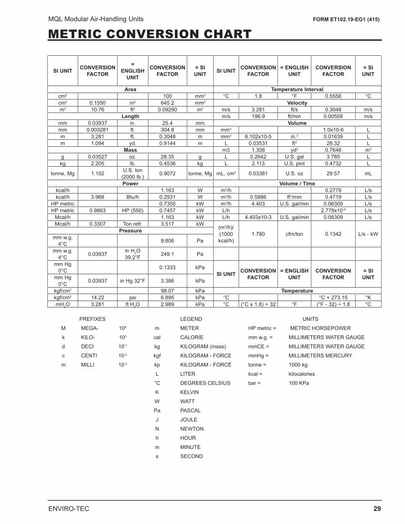
METRIC CONVERSION CHART
SI UNIT CONVERSION FACTOR
= ENGLISH
UNIT
CONVERSION FACTOR
= SI UNIT SI UNIT CONVERSION
FACTOR= ENGLISH
UNITCONVERSION
FACTOR= SI UNIT
Area Temperature Intervalcm2 100 mm2 °C 1.8 °F 0.5556 °Ccm2 0.1550 in2 645.2 mm2 Velocitym2 10.76 ft2 0.09290 m2 m/s 3.281 ft/s 0.3048 m/s
Length m/s 196.9 ft/min 0.00508 m/smm 0.03937 in. 25.4 mm Volumemm 0.003281 ft. 304.8 mm mm3 1.0x10⁻⁶ Lm 3.281 ft. 0.3048 m mm3 6.102x10⁻⁵ in.3 0.01639 Lm 1.094 yd. 0.9144 m L 0.03531 ft3 28.32 L
Mass m3 1.308 yd3 0.7646 m3
g 0.03527 oz. 28.35 g L 0.2642 U.S. gal 3.785 Lkg 2.205 lb. 0.4536 kg L 2.113 U.S. pint 0.4732 L
tonne, Mg 1.102 U.S. ton (2000 lb.) 0.9072 tonne, Mg mL, cm3 0.03381 U.S. oz 29.57 mL
Power Volume / Timekcal/h 1.163 W m3/h 0.2778 L/skcal/h 3.968 Btu/h 0.2931 W m3/h 0.5886 ft3/min 0.4719 L/s
HP metric 0.7355 kW m3/h 4.403 U.S. gal/min 0.06309 L/sHP metric 0.9863 HP (550) 0.7457 kW L/h 2.778x10⁻⁴ L/s
Mcal/h 1.163 kW L/h 4.403x10⁻³ U.S. gal/min 0.06309 L/sMcal/h 0.3307 Ton refr. 3.517 kW (m3/h)/
(1000 kcal/h)
1.780 cfm/ton 0.1342 L/s - kWPressuremm w.g.
4°C 9.806 Pa
mm w.g. 4°C 0.03937 in H2O
39.2°F 249.1 Pa
mm Hg 0°C 0.1333 kPa
SI UNIT CONVERSION FACTOR
= ENGLISH UNIT
CONVERSION FACTOR
= SI UNITmm Hg
0°C 0.03937 in Hg 32°F 3.386 kPa
kgf/cm2 98.07 kPa Temperaturekgf/cm2 14.22 psi 6.895 kPa °C °C + 273.15 °KmH2O 3.281 ft H2O 2.989 kPa °C (°C x 1.8) + 32 °F (°F - 32) ÷ 1.8 °C
PREFIXES LEGEND UNITS
M MEGA- 106 m METER HP metric = METRIC HORSEPOWER
k KILO- 103 cal CALORIE mm w.g. = MILLIMETERS WATER GAUGE
d DECI 10-1 kg KILOGRAM (mass) mmCE = MILLIMETERS WATER GAUGE
c CENTI 10-2 kgf KILOGRAM - FORCE mmHg = MILLIMETERS MERCURY
m MILLI 10-3 kp KILOGRAM - FORCE tonne = 1000 kg
L LITER kcal = kilocalories
°C DEGREES CELSIUS bar = 100 KPa
K KELVIN
W WATT
Pa PASCAL
J JOULE
N NEWTON
h HOUR
m MINUTE
s SECOND
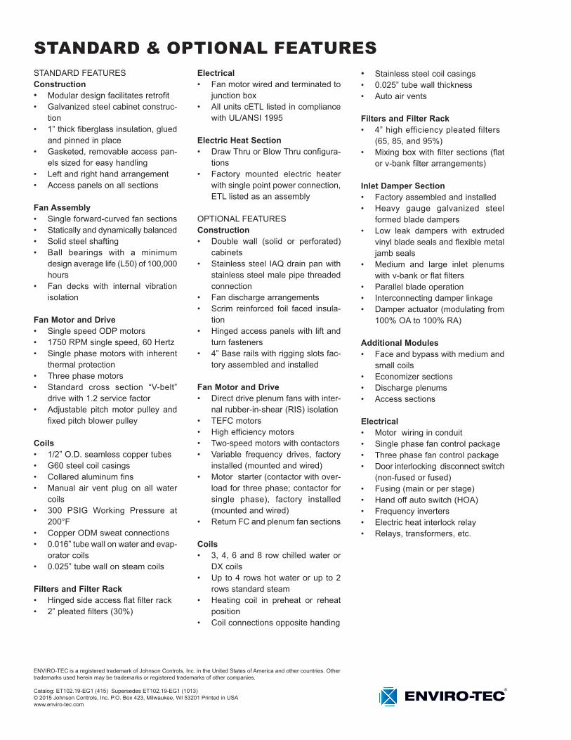
STANDARD & OPTIONAL FEATURESSTANDARD FEATURESConstruction• Modular design facilitates retrofit• Galvanized steel cabinet construc-
tion• 1” thick fiberglass insulation, glued
and pinned in place• Gasketed, removable access pan-
els sized for easy handling• Left and right hand arrangement• Access panels on all sections
Fan Assembly• Single forward-curved fan sections• Statically and dynamically balanced• Solid steel shafting• Ball bearings with a minimum
design average life (L50) of 100,000 hours
• Fan decks with internal vibration isolation
Fan Motor and Drive• Single speed ODP motors• 1750 RPM single speed, 60 Hertz• Single phase motors with inherent
thermal protection• Three phase motors• Standard cross section “V-belt”
drive with 1.2 service factor• Adjustable pitch motor pulley and
fixed pitch blower pulley
Coils• 1/2” O.D. seamless copper tubes• G60 steel coil casings• Collared aluminum fins• Manual air vent plug on all water
coils• 300 PSIG Working Pressure at
200°F• Copper ODM sweat connections• 0.016” tube wall on water and evap-
orator coils• 0.025” tube wall on steam coils
Filters and Filter Rack• Hinged side access flat filter rack• 2” pleated filters (30%)
Electrical• Fan motor wired and terminated to
junction box• All units cETL listed in compliance
with UL/ANSI 1995
Electric Heat Section• Draw Thru or Blow Thru configura-
tions• Factory mounted electric heater
with single point power connection, ETL listed as an assembly
OPTIONAL FEATURESConstruction• Double wall (solid or perforated)
cabinets• Stainless steel IAQ drain pan with
stainless steel male pipe threaded connection
• Fan discharge arrangements• Scrim reinforced foil faced insula-
tion• Hinged access panels with lift and
turn fasteners• 4” Base rails with rigging slots fac-
tory assembled and installed
Fan Motor and Drive• Direct drive plenum fans with inter-
nal rubber-in-shear (RIS) isolation• TEFC motors• High efficiency motors• Two-speed motors with contactors• Variable frequency drives, factory
installed (mounted and wired)• Motor starter (contactor with over-
load for three phase; contactor for single phase), factory installed (mounted and wired)
• Return FC and plenum fan sections
Coils• 3, 4, 6 and 8 row chilled water or
DX coils• Up to 4 rows hot water or up to 2
rows standard steam• Heating coil in preheat or reheat
position• Coil connections opposite handing
• Stainless steel coil casings• 0.025” tube wall thickness• Auto air vents Filters and Filter Rack• 4” high efficiency pleated filters
(65, 85, and 95%)• Mixing box with filter sections (flat
or v-bank filter arrangements)
Inlet Damper Section• Factory assembled and installed• Heavy gauge galvanized steel
formed blade dampers• Low leak dampers with extruded
vinyl blade seals and flexible metal jamb seals
• Medium and large inlet plenums with v-bank or flat filters
• Parallel blade operation• Interconnecting damper linkage• Damper actuator (modulating from
100% OA to 100% RA)
Additional Modules• Face and bypass with medium and
small coils• Economizer sections• Discharge plenums• Access sections
Electrical• Motor wiring in conduit• Single phase fan control package• Three phase fan control package• Door interlocking disconnect switch
(non-fused or fused)• Fusing (main or per stage)• Hand off auto switch (HOA)• Frequency inverters• Electric heat interlock relay• Relays, transformers, etc.
ENVIRO-TEC is a registered trademark of Johnson Controls, Inc. in the United States of America and other countries. Other trademarks used herein may be trademarks or registered trademarks of other companies.
Catalog: ET102.19-EG1 (415) Supersedes ET102.19-EG1 (1013)© 2015 Johnson Controls, Inc. P.O. Box 423, Milwaukee, WI 53201 Printed in USAwww.enviro-tec.com