Embed Size (px)
Citation preview
BALOGH 3637 Old US-23 Suite 100 Brighton, MI 48114 – (810) 360-0182 - Subject to Modifications
MRUC-20 Modul-R CAN Bus Network
BALOGH
This manual is based on information available at the time if its publication. Every effort has been made to provide accurate and up-to-date information. This document does not purport to cover all details or variations in hardware or software; nor does it provide for every possible combination of products. Some features described herein may not be available on all like products. BALOGH assumes no obligation to notify holders of this document of any subsequent changes. BALOGH makes no representations or warranty, expressed, implied, or statutory with respect to, and assumes no responsibility for the accuracy, completeness, or usefulness of the information contained in this manual. No warranties of merchantability or fitness for purpose shall apply. © Copyright BALOGH 2001
BALOGH 3637 Old US-23 Suite 100 Brighton, MI 48114 – (810) 360-0182 - Subject to Modifications
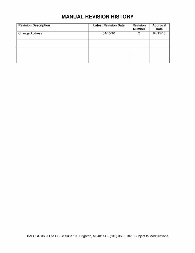
MANUAL REVISION HISTORY
Revision Description Latest Revision Date Revision Number
Approval Date
Change Address 04/15/10 2 04/15/10
BALOGH 3637 Old US-23 Suite 100 Brighton, MI 48114 – (810) 360-0182 - Subject to Modifications
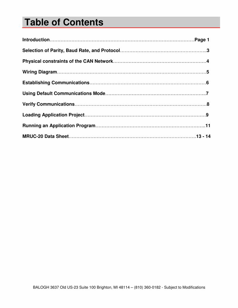
Table of Contents
Introduction…………………………………………………………………………………Page 1 Selection of Parity, Baud Rate, and Protocol………………………………………………..3 Physical constraints of the CAN Network……………………………………………………4 Wiring Diagram……………………………………………………………………………………5 Establishing Communications…………………………………………………………………6 Using Default Communications Mode………………………………………………………..7 Verify Communications………………………………………………………………………….8 Loading Application Project……………………………………………………………………9 Running an Application Program……………………………………………………………..11 MRUC-20 Data Sheet……………………………………………………………………….13 - 14

BALOGH 3637 Old US-23 Suite 100 Brighton, MI 48114 – (810) 360-0182 - Subject to Modifications
BALOGH 3637 Old US-23 Suite 100 Brighton, MI 48114 – (810) 360-0182 - Subject to Modifications
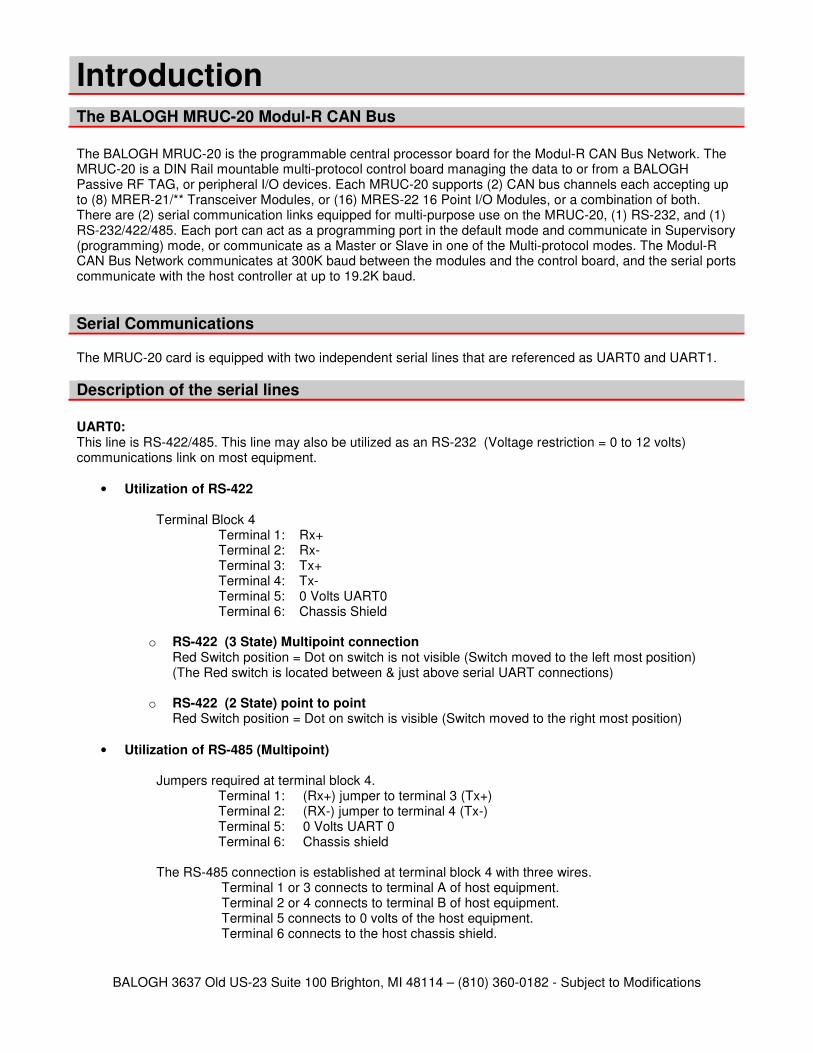
The BALOGH MRUC-20 Modul-R CAN Bus
The BALOGH MRUC-20 is the programmable central processor board for the Modul-R CAN Bus Network. The MRUC-20 is a DIN Rail mountable multi-protocol control board managing the data to or from a BALOGH Passive RF TAG, or peripheral I/O devices. Each MRUC-20 supports (2) CAN bus channels each accepting up to (8) MRER-21/** Transceiver Modules, or (16) MRES-22 16 Point I/O Modules, or a combination of both. There are (2) serial communication links equipped for multi-purpose use on the MRUC-20, (1) RS-232, and (1) RS-232/422/485. Each port can act as a programming port in the default mode and communicate in Supervisory (programming) mode, or communicate as a Master or Slave in one of the Multi-protocol modes. The Modul-R CAN Bus Network communicates at 300K baud between the modules and the control board, and the serial ports communicate with the host controller at up to 19.2K baud.
Serial Communications The MRUC-20 card is equipped with two independent serial lines that are referenced as UART0 and UART1.
Description of the serial lines
UART0: This line is RS-422/485. This line may also be utilized as an RS-232 (Voltage restriction = 0 to 12 volts) communications link on most equipment.
• Utilization of RS-422 Terminal Block 4
Terminal 1: Rx+ Terminal 2: Rx- Terminal 3: Tx+ Terminal 4: Tx- Terminal 5: 0 Volts UART0 Terminal 6: Chassis Shield
o RS-422 (3 State) Multipoint connection
Red Switch position = Dot on switch is not visible (Switch moved to the left most position) (The Red switch is located between & just above serial UART connections)
o RS-422 (2 State) point to point
Red Switch position = Dot on switch is visible (Switch moved to the right most position)
• Utilization of RS-485 (Multipoint)
Jumpers required at terminal block 4. Terminal 1: (Rx+) jumper to terminal 3 (Tx+) Terminal 2: (RX-) jumper to terminal 4 (Tx-) Terminal 5: 0 Volts UART 0 Terminal 6: Chassis shield
The RS-485 connection is established at terminal block 4 with three wires.
Terminal 1 or 3 connects to terminal A of host equipment. Terminal 2 or 4 connects to terminal B of host equipment. Terminal 5 connects to 0 volts of the host equipment. Terminal 6 connects to the host chassis shield.
Introduction
BALOGH 3637 Old US-23 Suite 100 Brighton, MI 48114 – (810) 360-0182 - Subject to Modifications
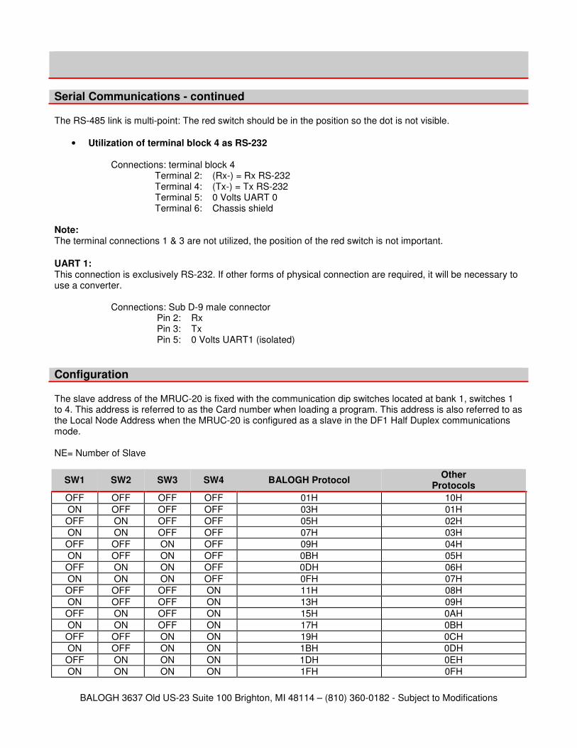
Serial Communications - continued The RS-485 link is multi-point: The red switch should be in the position so the dot is not visible.
• Utilization of terminal block 4 as RS-232
Connections: terminal block 4 Terminal 2: (Rx-) = Rx RS-232 Terminal 4: (Tx-) = Tx RS-232 Terminal 5: 0 Volts UART 0 Terminal 6: Chassis shield
Note: The terminal connections 1 & 3 are not utilized, the position of the red switch is not important.
UART 1: This connection is exclusively RS-232. If other forms of physical connection are required, it will be necessary to use a converter.
Connections: Sub D-9 male connector Pin 2: Rx Pin 3: Tx Pin 5: 0 Volts UART1 (isolated)
Configuration The slave address of the MRUC-20 is fixed with the communication dip switches located at bank 1, switches 1 to 4. This address is referred to as the Card number when loading a program. This address is also referred to as the Local Node Address when the MRUC-20 is configured as a slave in the DF1 Half Duplex communications mode. NE= Number of Slave
SW1 SW2 SW3 SW4 BALOGH Protocol Other
Protocols
OFF OFF OFF OFF 01H 10H
ON OFF OFF OFF 03H 01H
OFF ON OFF OFF 05H 02H
ON ON OFF OFF 07H 03H
OFF OFF ON OFF 09H 04H
ON OFF ON OFF 0BH 05H
OFF ON ON OFF 0DH 06H
ON ON ON OFF 0FH 07H
OFF OFF OFF ON 11H 08H
ON OFF OFF ON 13H 09H
OFF ON OFF ON 15H 0AH
ON ON OFF ON 17H 0BH
OFF OFF ON ON 19H 0CH
ON OFF ON ON 1BH 0DH
OFF ON ON ON 1DH 0EH
ON ON ON ON 1FH 0FH
BALOGH 3637 Old US-23 Suite 100 Brighton, MI 48114 – (810) 360-0182 - Subject to Modifications
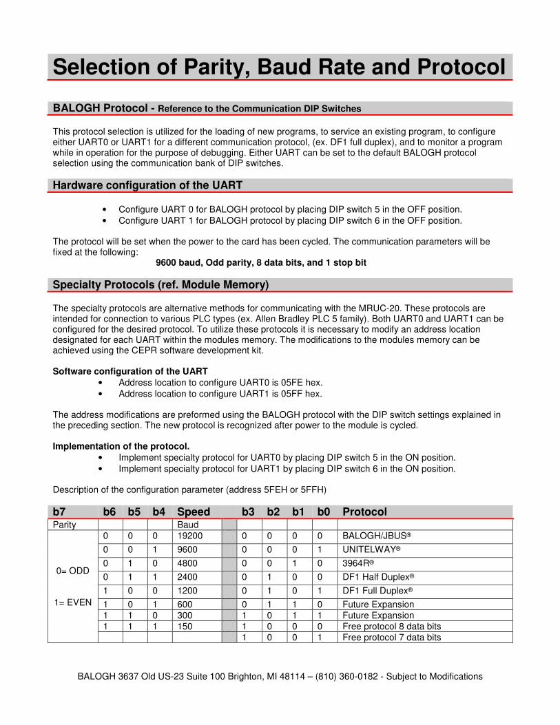
BALOGH Protocol - Reference to the Communication DIP Switches This protocol selection is utilized for the loading of new programs, to service an existing program, to configure either UART0 or UART1 for a different communication protocol, (ex. DF1 full duplex), and to monitor a program while in operation for the purpose of debugging. Either UART can be set to the default BALOGH protocol selection using the communication bank of DIP switches.
Hardware configuration of the UART
• Configure UART 0 for BALOGH protocol by placing DIP switch 5 in the OFF position.
• Configure UART 1 for BALOGH protocol by placing DIP switch 6 in the OFF position. The protocol will be set when the power to the card has been cycled. The communication parameters will be fixed at the following:
9600 baud, Odd parity, 8 data bits, and 1 stop bit
Specialty Protocols (ref. Module Memory) The specialty protocols are alternative methods for communicating with the MRUC-20. These protocols are intended for connection to various PLC types (ex. Allen Bradley PLC 5 family). Both UART0 and UART1 can be configured for the desired protocol. To utilize these protocols it is necessary to modify an address location designated for each UART within the modules memory. The modifications to the modules memory can be achieved using the CEPR software development kit. Software configuration of the UART
• Address location to configure UART0 is 05FE hex.
• Address location to configure UART1 is 05FF hex. The address modifications are preformed using the BALOGH protocol with the DIP switch settings explained in the preceding section. The new protocol is recognized after power to the module is cycled. Implementation of the protocol.
• Implement specialty protocol for UART0 by placing DIP switch 5 in the ON position.
• Implement specialty protocol for UART1 by placing DIP switch 6 in the ON position. Description of the configuration parameter (address 5FEH or 5FFH)
b7 b6 b5 b4 Speed b3 b2 b1 b0 Protocol Parity Baud
0= ODD
1= EVEN
0 0 0 19200 0 0 0 0 BALOGH/JBUS®
0 0 1 9600 0 0 0 1 UNITELWAY®
0 1 0 4800 0 0 1 0 3964R®
0 1 1 2400 0 1 0 0 DF1 Half Duplex®
1 0 0 1200 0 1 0 1 DF1 Full Duplex®
1 0 1 600 0 1 1 0 Future Expansion
1 1 0 300 1 0 1 1 Future Expansion
1 1 1 150 1 0 0 0 Free protocol 8 data bits
1 0 0 1 Free protocol 7 data bits
Selection of Parity, Baud Rate and Protocol
BALOGH 3637 Old US-23 Suite 100 Brighton, MI 48114 – (810) 360-0182 - Subject to Modifications
Physical constraints of the CAN Network
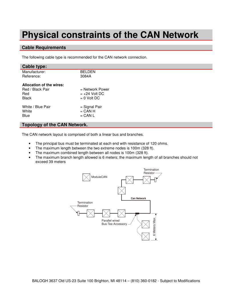
The following cable type is recommended for the CAN network connection.
Cable type: Manufacturer: BELDEN Reference: 3084A Allocation of the wires: Red / Black Pair = Network Power Red = +24 Volt DC Black = 0 Volt DC White / Blue Pair = Signal Pair White = CAN H Blue = CAN L
Topology of the CAN Network. The CAN network layout is comprised of both a linear bus and branches.
• The principal bus must be terminated at each end with resistance of 120 ohms.
• The maximum length between the two extreme nodes is 100m (328 ft).
• The maximum combined length between all nodes is 100m (328 ft).
• The maximum branch length allowed is 6 meters; the maximum length of all branches should not exceed 39 meters
Can Network
Termination Resistor
ModuleCAN
Termination Resistor
Parallel wiredBus-Tee Accessory
6 M
ete
rs M
ax.
Cable Requirements
BALOGH 3637 Old US-23 Suite 100 Brighton, MI 48114 – (810) 360-0182 - Subject to Modifications
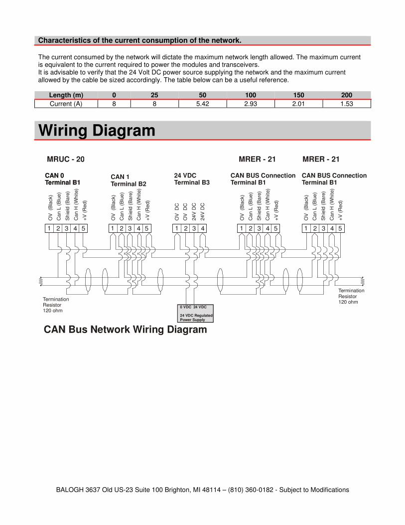
Characteristics of the current consumption of the network. The current consumed by the network will dictate the maximum network length allowed. The maximum current is equivalent to the current required to power the modules and transceivers. It is advisable to verify that the 24 Volt DC power source supplying the network and the maximum current allowed by the cable be sized accordingly. The table below can be a useful reference.
Length (m) 0 25 50 100 150 200
Current (A) 8 8 5.42 2.93 2.01 1.53
1 2 3 4 5 1 2 3 4 5 1 2 3 4 1 2 3 4 5 1 2 3 4 5
0 VDC 24 VDC
24 VDC RegulatedPower Supply
TerminationResistor120 ohm
TerminationResistor120 ohm
OV
(B
lack)
Ca
n L
(B
lue
)
Sh
ield
(B
are
)
Ca
n H
(W
hite)
+V
(R
ed)
OV
(B
lack)
Ca
n L
(B
lue
)
Sh
ield
(B
are
)
Ca
n H
(W
hite)
+V
(R
ed)
OV
(B
lack)
Ca
n L
(B
lue
)
Sh
ield
(B
are
)
Ca
n H
(W
hite)
+V
(R
ed)
OV
(B
lack)
Ca
n L
(B
lue
)
Sh
ield
(B
are
)
Ca
n H
(W
hite)
+V
(R
ed)
OV
D
C
24
V D
C
OV
D
C
24
V D
C
CAN 0Terminal B1
24 VDCTerminal B3
CAN BUS Connection Terminal B1
CAN BUS Connection Terminal B1
MRUC - 20 MRER - 21 MRER - 21
CAN Bus Network Wiring Diagram
CAN 0Terminal B1
CAN 1Terminal B2
Wiring Diagram
BALOGH 3637 Old US-23 Suite 100 Brighton, MI 48114 – (810) 360-0182 - Subject to Modifications
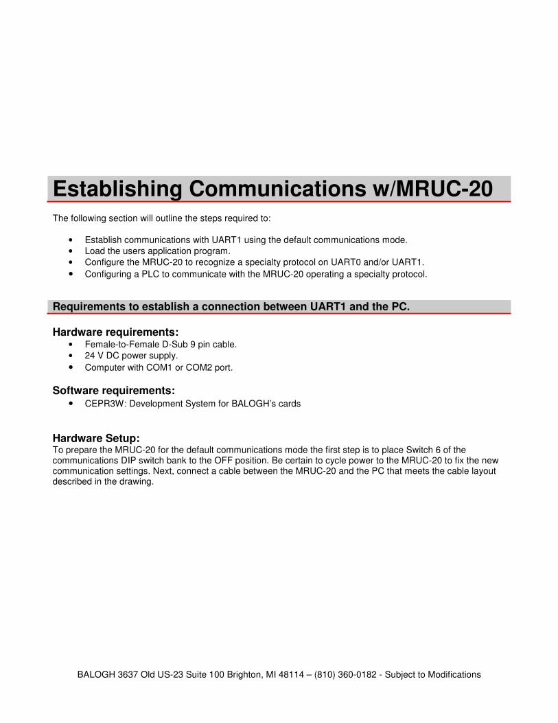
Establishing Communications w/MRUC-20 The following section will outline the steps required to:
• Establish communications with UART1 using the default communications mode.
• Load the users application program.
• Configure the MRUC-20 to recognize a specialty protocol on UART0 and/or UART1.
• Configuring a PLC to communicate with the MRUC-20 operating a specialty protocol.
Requirements to establish a connection between UART1 and the PC.
Hardware requirements: • Female-to-Female D-Sub 9 pin cable.
• 24 V DC power supply.
• Computer with COM1 or COM2 port.
Software requirements: • CEPR3W: Development System for BALOGH’s cards
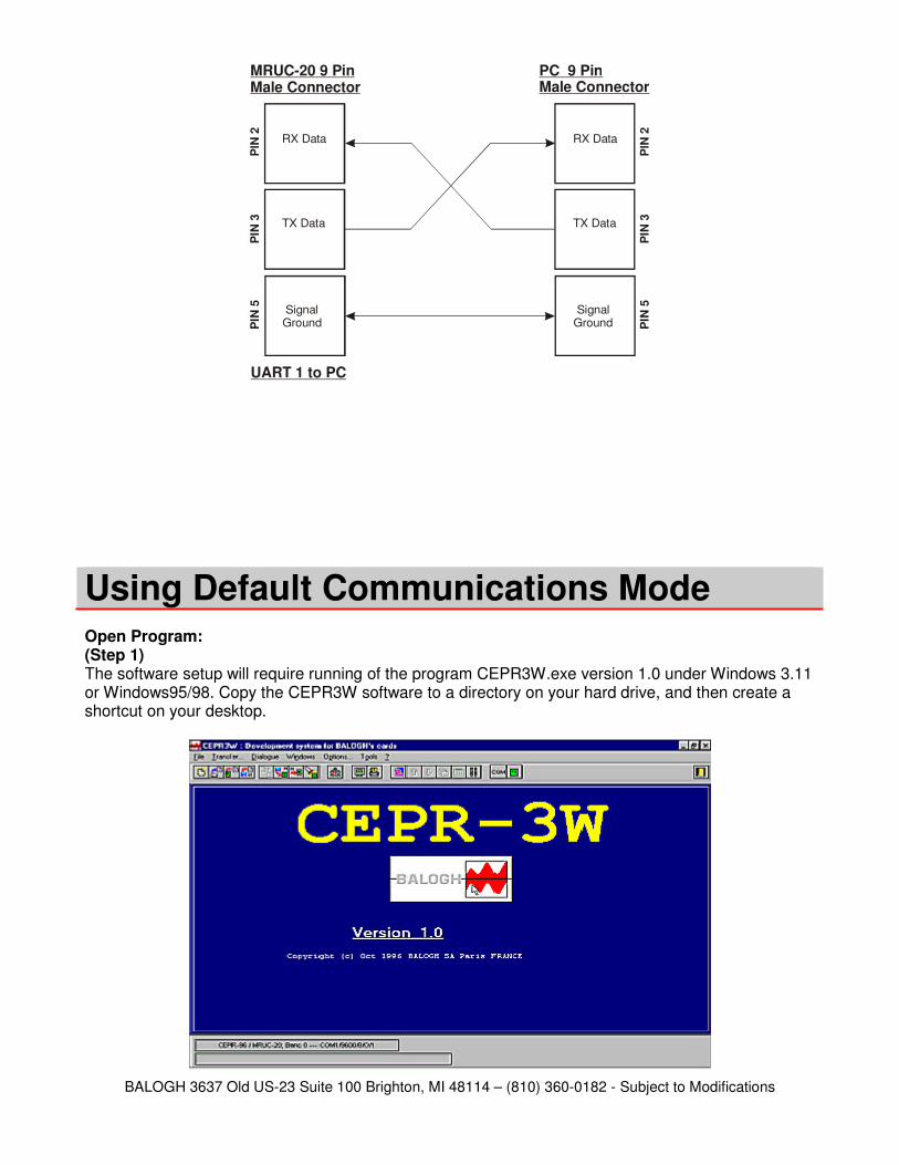
Hardware Setup: To prepare the MRUC-20 for the default communications mode the first step is to place Switch 6 of the communications DIP switch bank to the OFF position. Be certain to cycle power to the MRUC-20 to fix the new communication settings. Next, connect a cable between the MRUC-20 and the PC that meets the cable layout described in the drawing.
BALOGH 3637 Old US-23 Suite 100 Brighton, MI 48114 – (810) 360-0182 - Subject to Modifications
PIN
2P
IN 3
PIN
5
MRUC-20 9 PinMale Connector
PIN
2P
IN 3
PIN
5
RX Data
TX Data
SignalGround
RX Data
TX Data
SignalGround
PC 9 PinMale Connector
UART 1 to PC
Using Default Communications Mode
Open Program: (Step 1) The software setup will require running of the program CEPR3W.exe version 1.0 under Windows 3.11 or Windows95/98. Copy the CEPR3W software to a directory on your hard drive, and then create a shortcut on your desktop.
BALOGH 3637 Old US-23 Suite 100 Brighton, MI 48114 – (810) 360-0182 - Subject to Modifications
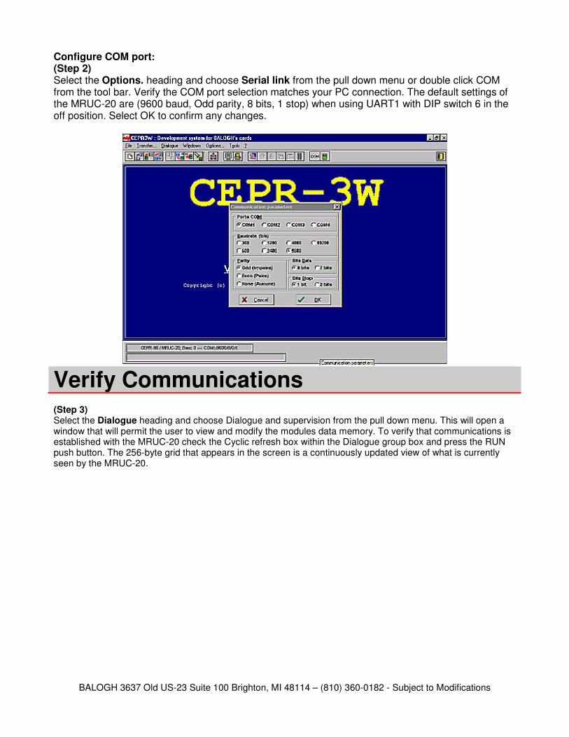
Configure COM port: (Step 2) Select the Options. heading and choose Serial link from the pull down menu or double click COM from the tool bar. Verify the COM port selection matches your PC connection. The default settings of the MRUC-20 are (9600 baud, Odd parity, 8 bits, 1 stop) when using UART1 with DIP switch 6 in the off position. Select OK to confirm any changes.
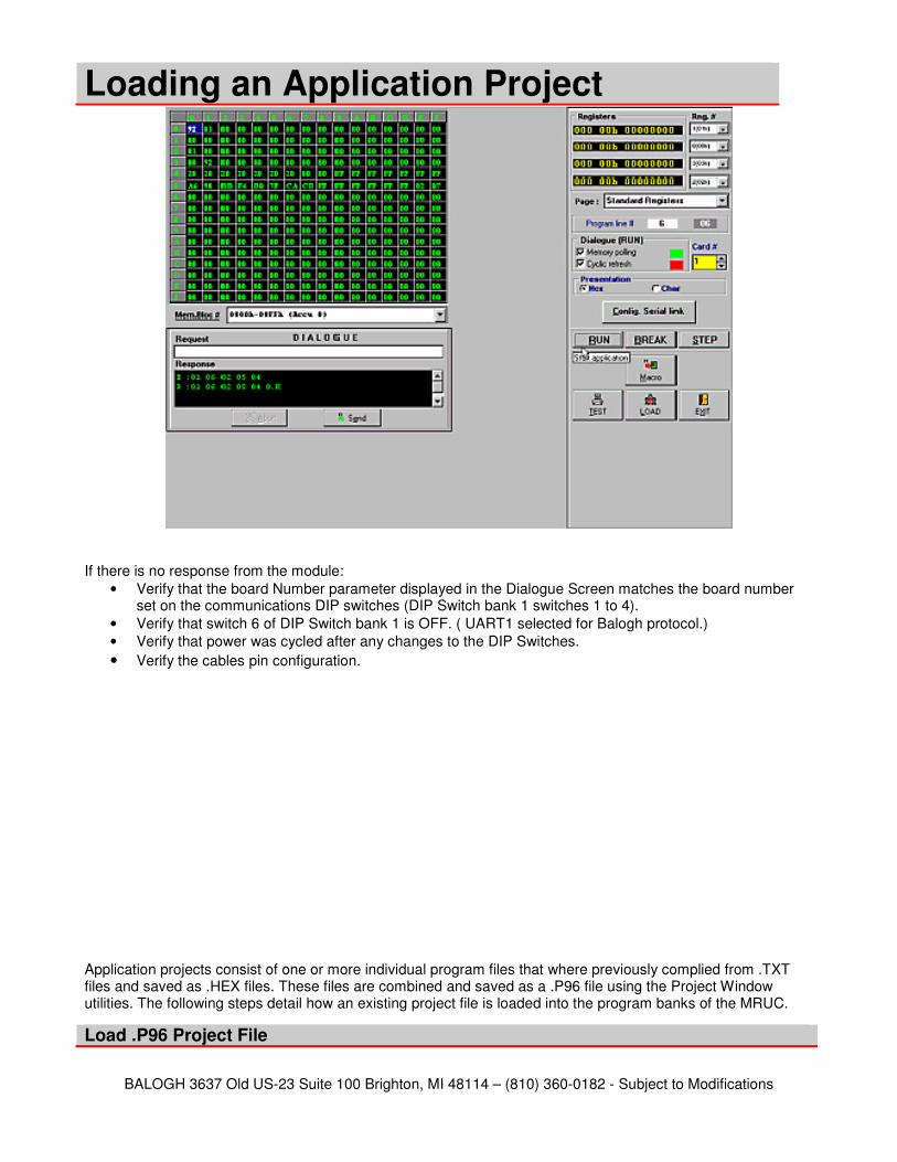
(Step 3) Select the Dialogue heading and choose Dialogue and supervision from the pull down menu. This will open a window that will permit the user to view and modify the modules data memory. To verify that communications is established with the MRUC-20 check the Cyclic refresh box within the Dialogue group box and press the RUN push button. The 256-byte grid that appears in the screen is a continuously updated view of what is currently seen by the MRUC-20.
Verify Communications
BALOGH 3637 Old US-23 Suite 100 Brighton, MI 48114 – (810) 360-0182 - Subject to Modifications
If there is no response from the module:
• Verify that the board Number parameter displayed in the Dialogue Screen matches the board number set on the communications DIP switches (DIP Switch bank 1 switches 1 to 4).
• Verify that switch 6 of DIP Switch bank 1 is OFF. ( UART1 selected for Balogh protocol.)
• Verify that power was cycled after any changes to the DIP Switches.
• Verify the cables pin configuration.
Application projects consist of one or more individual program files that where previously complied from .TXT files and saved as .HEX files. These files are combined and saved as a .P96 file using the Project Window utilities. The following steps detail how an existing project file is loaded into the program banks of the MRUC.
Load .P96 Project File
Loading an Application Project
BALOGH 3637 Old US-23 Suite 100 Brighton, MI 48114 – (810) 360-0182 - Subject to Modifications
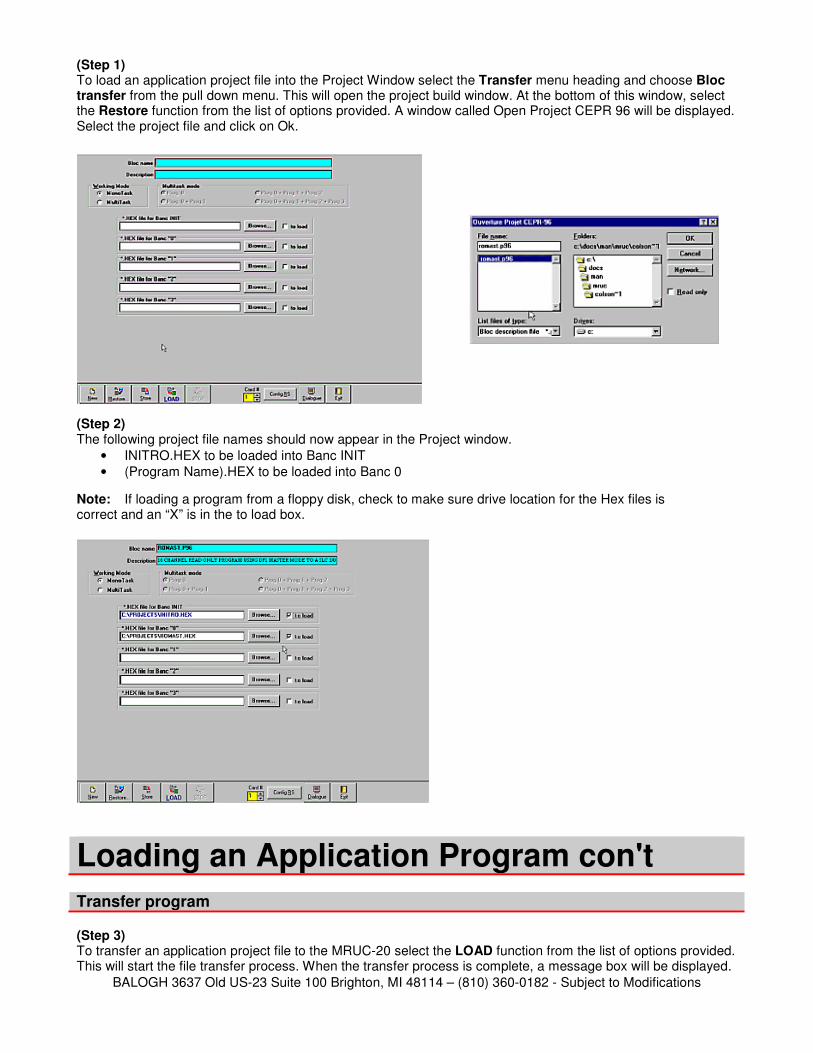
(Step 1) To load an application project file into the Project Window select the Transfer menu heading and choose Bloc transfer from the pull down menu. This will open the project build window. At the bottom of this window, select the Restore function from the list of options provided. A window called Open Project CEPR 96 will be displayed. Select the project file and click on Ok.
(Step 2) The following project file names should now appear in the Project window.
• INITRO.HEX to be loaded into Banc INIT
• (Program Name).HEX to be loaded into Banc 0
Note: If loading a program from a floppy disk, check to make sure drive location for the Hex files is correct and an “X” is in the to load box.
Loading an Application Program con't
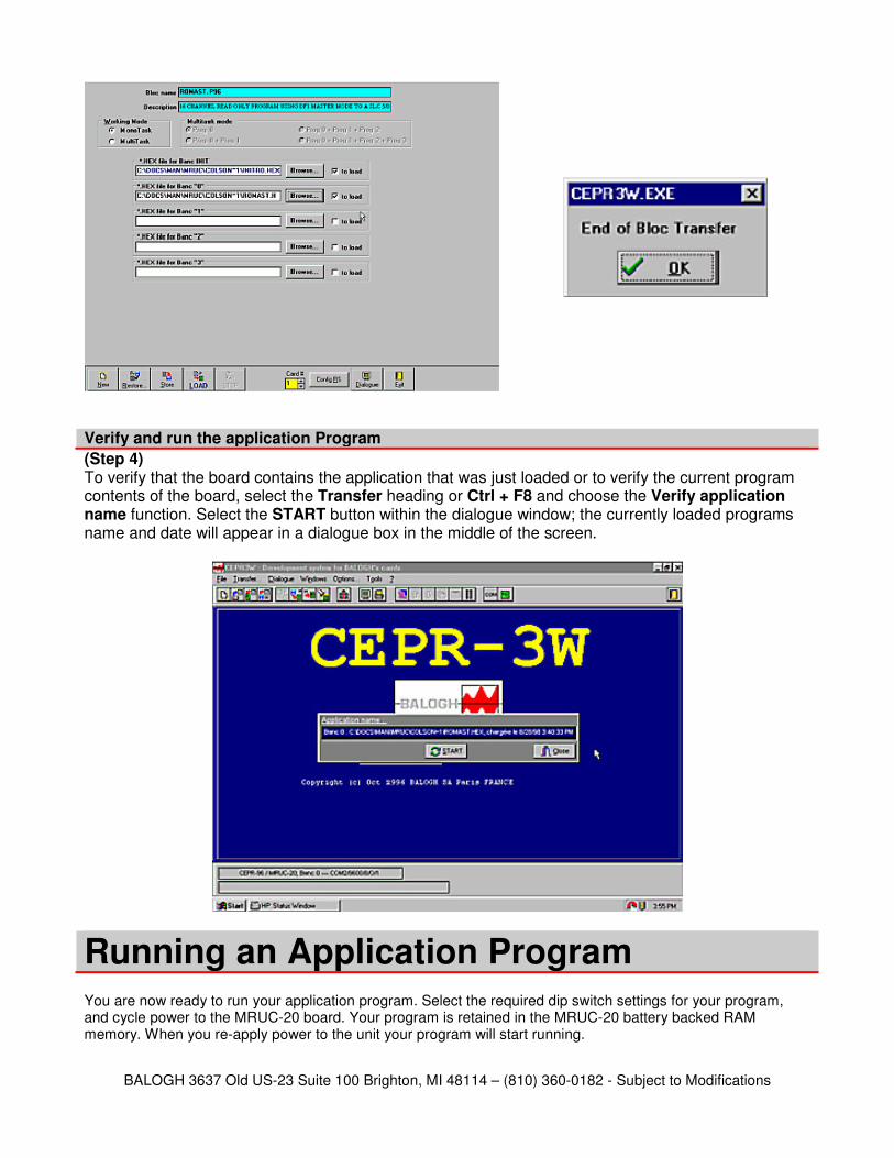
Transfer program (Step 3) To transfer an application project file to the MRUC-20 select the LOAD function from the list of options provided. This will start the file transfer process. When the transfer process is complete, a message box will be displayed.
BALOGH 3637 Old US-23 Suite 100 Brighton, MI 48114 – (810) 360-0182 - Subject to Modifications
Verify and run the application Program (Step 4) To verify that the board contains the application that was just loaded or to verify the current program contents of the board, select the Transfer heading or Ctrl + F8 and choose the Verify application name function. Select the START button within the dialogue window; the currently loaded programs name and date will appear in a dialogue box in the middle of the screen.
Running an Application Program
You are now ready to run your application program. Select the required dip switch settings for your program, and cycle power to the MRUC-20 board. Your program is retained in the MRUC-20 battery backed RAM memory. When you re-apply power to the unit your program will start running.
BALOGH 3637 Old US-23 Suite 100 Brighton, MI 48114 – (810) 360-0182 - Subject to Modifications
Anytime an adjustment is made to the MRUC-20 (i.e. dip switch settings) or any other device on the CAN Bus, power must be cycled for those changes to take affect.
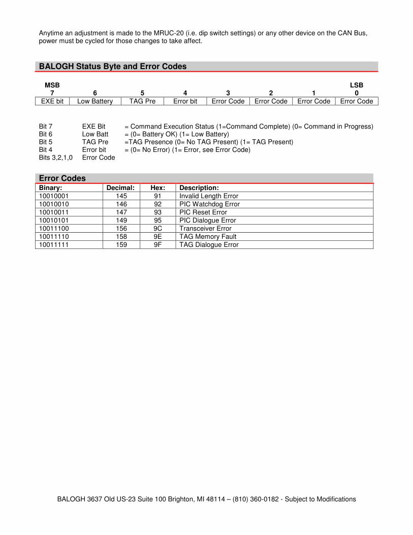
BALOGH Status Byte and Error Codes
MSB LSB
7 6 5 4 3 2 1 0
EXE bit Low Battery TAG Pre Error bit Error Code Error Code Error Code Error Code
Bit 7 EXE Bit = Command Execution Status (1=Command Complete) (0= Command in Progress) Bit 6 Low Batt = (0= Battery OK) (1= Low Battery) Bit 5 TAG Pre =TAG Presence (0= No TAG Present) (1= TAG Present) Bit 4 Error bit = (0= No Error) (1= Error, see Error Code) Bits 3,2,1,0 Error Code
Error Codes
Binary: Decimal: Hex: Description:
10010001 145 91 Invalid Length Error
10010010 146 92 PIC Watchdog Error
10010011 147 93 PIC Reset Error
10010101 149 95 PIC Dialogue Error
10011100 156 9C Transceiver Error
10011110 158 9E TAG Memory Fault
10011111 159 9F TAG Dialogue Error
BALOGH 3637 Old US-23 Suite 100 Brighton, MI 48114 – (810) 360-0182 - Subject to Modifications
Characteristics
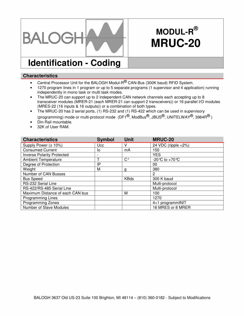
• Central Processor Unit for the BALOGH Modul-R® CAN-Bus (300K baud) RFID System.
• 1270 program lines in 1 program or up to 5 separate programs (1 supervisor and 4 application) running independently in mono task or multi task modes.
• The MRUC-20 can support up to 2 independent CAN network channels each accepting up to 8 transceiver modules (MRER-21 (each MRER-21 can support 2 transceivers)) or 16 parallel I/O modules (MRES-22 (16 inputs & 16 outputs)) or a combination of both types.
• The MRUC-20 has 2 serial ports, (1) RS-232 and (1) RS-422 which can be used in supervisory
(programming) mode or multi-protocol mode (DF1®, ModBus®, JBUS®, UNITELWAY®, 3964R® )
• Din-Rail mountable.
• 32K of User RAM.
Characteristics Symbol Unit MRUC-20 Supply Power (± 10%) Ucc V 24 VDC (ripple <2%)
Consumed Current Io mA 150
Inverse Polarity Protected - YES
Ambient Temperature T C° -20°C to +70°C
Degree of Protection IP 00
Weight M g 380
Number of CAN Busses 2
Bus Speed KBds 300 K baud
RS-232 Serial Line Multi-protocol
RS-422/RS-485 Serial Line Multi-protocol
Maximum Distance of each CAN bus M 100
Programming Lines 1270
Programming Zones 4+1 programmINIT
Number of Slave Modules 16 MRES or 8 MRER
MODUL-R®
MRUC-20
Identification - Coding
BALOGH 3637 Old US-23 Suite 100 Brighton, MI 48114 – (810) 360-0182 - Subject to Modifications
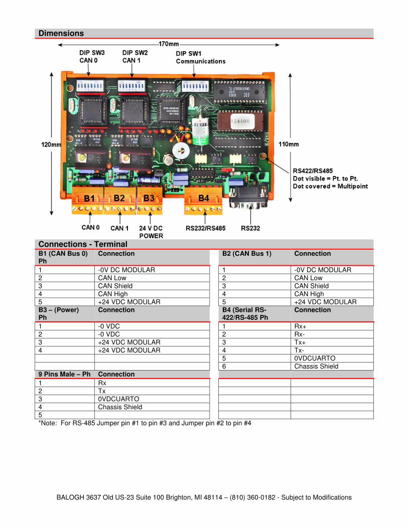
Dimensions
Connections - Terminal B1 (CAN Bus 0) Ph
Connection B2 (CAN Bus 1) Connection
1 -0V DC MODULAR 1 -0V DC MODULAR
2 CAN Low 2 CAN Low
3 CAN Shield 3 CAN Shield
4 CAN High 4 CAN High
5 +24 VDC MODULAR 5 +24 VDC MODULAR B3 – (Power) Ph
Connection B4 (Serial RS-422/RS-485 Ph
Connection
1 -0 VDC 1 Rx+
2 -0 VDC 2 Rx-
3 +24 VDC MODULAR 3 Tx+
4 +24 VDC MODULAR 4 Tx-
5 0VDCUARTO
6 Chassis Shield 9 Pins Male – Ph Connection
1 Rx
2 Tx
3 0VDCUARTO
4 Chassis Shield
5
*Note: For RS-485 Jumper pin #1 to pin #3 and Jumper pin #2 to pin #4

BALOGH 3637 Old US-23 Suite 100 Brighton, MI 48114 – (810) 360-0182 - Subject to Modifications