Embed Size (px)
Citation preview
Multi-Fastener Single-lap Joints in Composite Structures
Johan EkhDepartment of Aeronautical and Vehicle Engineering
Royal Institute of TechnologySE–100 44 Stockholm, Sweden
Doctoral Thesis in Lightweight StructuresTRITA AVE: 2006-22
ISSN 1651-7660ISBN 91-7178-396-2

Preface
The work presented in this doctoral thesis has been carried out between January2000 and May 2006. Work between January 2000 and December 2003 was conductedat the Royal Institute of Technology, Department of Aeronautical and Vehicle En-gineering and the remaining part was performed on part time basis at ABB AB,Corporate Research. A major part of the work was conducted within the frameworkof BOJCAS - BOlted Joints in Composite Aircraft Structures, a RTD project par-tially funded by the European Union under the European Commission GROWTHprogramme, ’New Perspectives in Aeronautics’. All experiments were performed atThe Swedish Defence Research Agency (FOI). The support from these organizationsis gratefully acknowledged.
Firstly, I would like to thank my co-author Dr. Joakim Schon for his consistentsupport and encouragement. His knowledge and experience in the field of compositebolted joints have been invaluable to my research. I also want to thank Professor DanZenkert for accepting the role as my supervisor during the second part of my work.Professor Jan Backlund is acknowledged for accepting me as a graduate student.
Finally, I thank my fiance Anna-Karin and our children, Oskar, Matilda andSofia, for their support and patience. This work would not have been completedwithout their support.
Vasteras, May 2006
Johan Ekh
i

Abstract
This thesis deals with composite joints. Designing such joints is more difficult thanmetallic joints due to the mechanical properties of composite materials. Compositesare anisotropic and have a limited ability of yielding. The low degree of yieldingmeans that stress concentrations are not relieved by plastic deformation, whichis important in multi-fastener single-lap joints. The distribution of load betweenthe fasteners may be more uneven than in metallic joints due to that the stressconcentrations around the holes are not relieved. Single-lap joints have an eccentricload path which generates a nonuniform bolt-hole contact pressure through the platethickness. This generates out-of-plane deflection of the joint, termed secondarybending. Such nonuniform contact stress severely limits the strength of the joint.The nonuniform contact stress distribution is affected by several factors, e.g. bolt-hole clearance and secondary bending.
The first part of the work is devoted to investigating secondary bending, and itseffect on stresses in the joint. A novel technique to study secondary bending has beendeveloped and used in a parametric study. It is based on the calculation of specimencurvature from out-of-plane deflections measured with an optical technique. It isshown that the specimen curvature is correlated to the conventional definition ofsecondary bending, which involves strain measurements on both sides of the plate.The two most important parameters affecting specimen curvature was found to bethe overlap length and the thickness of the plates. The finite element method wasused to study the influence of secondary bending on joint strength. Secondarybending was changed in magnitude by altering the length of the overlap region in atwo-fastener specimen. It was found that secondary bending affects the local stressfield around the fasteners and that it may change the strength and the mode offailure.
The second part is concerned with the load distribution and prediction of jointstrength. A detailed finite element model was developed to calculate the load distri-bution while accounting for bolt-hole clearances, bolt clamp-up, secondary bendingand friction. An experimental programme was conducted in order to validate thefinite element model by means of instrumented fasteners. Good agreement betweensimulations and experiments was achieved and it was found that bolt-hole clearanceis the most important factor in terms of load distribution between the fasteners. Sen-sitivity to this parameter was found to be large, implying that temperature changescould affect the load distribution if member plates with different thermal expansionproperties are used.
Calculating the load distribution in structures with a large number of fastenersis in general not feasible with detailed finite element models based on continuumelements. A simplified, computationally effective model of a multi-fastener, single-lap joint has been developed by means of structural finite elements. The modelaccounts for bolt-hole clearances, bolt clamp-up, secondary bending and friction.Comparisons with the detailed finite element model and experiments validated theaccuracy of the simplified model. A parametric study was conducted where it wasfound that an increased stiffness mismatch between the plates generates a moreuneven load distribution, while reducing the length of the overlap region has theopposite effect. Increasing the stiffness of a fastener shifts some of the load from
iii
the nearest fasteners to that particular fastener. An idealized optimization studywas conducted in order to minimize bearing stresses in the joint with restrictionson the increase of joint weight and net-section stresses. Maximum bearing stresswas reduced from 220 MPa to 120 MPa while both weight and net-section stressesdecreased.
A procedure to predict bearing strength based on the results from the simpli-fied model was developed. It was established by an experimental programme thatfiber micro-buckling is the initial failure mode. The stress state in the laminatewas determined through force and moment equilibrium, based on output from thefinite element model. An existing criterion was used to predict the fiber micro-buckling, and thus the initial failure. Predictions were compared with experimentswhich validated the method. The small computational cost required by the proce-dure suggests that the method is applicable on large scale structures and suitableto use in conjunction with iterative schemes such as optimization and statisticalinvestigations.
iv
Dissertation
This doctoral thesis contains an introduction to the research area and the followingappended papers:
Paper A
J. Ekh, J. Schon, L. G. Melin, Secondary Bending in Multi Fastener, Composite-to-Aluminium Single Shear Lap Joints, Composites Part B, 36, (2005), 195-208.
Paper B
J. Ekh, J. Schon, Effect of Secondary Bending on Strength Prediction of Composite,Single Shear Lap Joints, Composites Science and Technology, 65, (2005), 953-965.
Paper-C
J. Ekh, J. Schon, Load Transfer in Multirow, Single Shear, Composite-to-AluminiumLap Joints, Composites Science and Technology, 66, (2006), 875-885.
Paper D
J. Ekh, J. Schon, Finite Element Modeling and optimization of Load Transfer inMulti-Fastener Joints using Structural Elements, Accepted for publication in Com-posite Structures.
Paper E
J. Ekh, D. Zenkert, J. Schon, Prediction of Bearing Failure in Composite Single-lapJoints, To be submitted for publication in Journal of Composite Materials.
v


Division of work between authors
Paper A
Ekh and Schon planned the experimental programme. Ekh and Melin conductedthe experiments. Ekh conducted the FE-analyses. Ekh and Schon wrote the paper.
Paper B
Ekh conducted the FE-analyses. Ekh and Schon wrote the paper.
Paper C
Ekh and Schon planned the experimental programme. Ekh conducted the experi-ments and the FE-analyses. Ekh wrote the paper with help from Schon.
Paper D
Ekh and Schon planned the experimental programme. Ekh conducted the experi-ments and the FE-analyses. Ekh wrote the paper with help from Schon.
Paper E
Ekh and Schon planned the experimental programme and Ekh conducted the ex-periments. Ekh and Zenkert outlined the numerical and analytical procedure. Ekhimplemented the numerical routine and performed the analyses. Ekh wrote thepaper with help from Zenkert and Schon.
vii

Contents
Preface i
Abstract iv
Dissertation v
Division of work between authors vii
1. Introduction 1
1.1. Background . . . . . . . . . . . . . . . . . . . . . . . . . . . . . . . . 11.2. Failure in composite joints . . . . . . . . . . . . . . . . . . . . . . . . 41.3. Stress analysis . . . . . . . . . . . . . . . . . . . . . . . . . . . . . . . 81.4. Strength prediction . . . . . . . . . . . . . . . . . . . . . . . . . . . . 151.5. Future work . . . . . . . . . . . . . . . . . . . . . . . . . . . . . . . . 22
References 28
Paper A A1–A22
Paper B B1–B21
Paper C C1–C19
Paper D D1–D21
Paper E E1–E21
ix

1. Introduction
1.1. Background
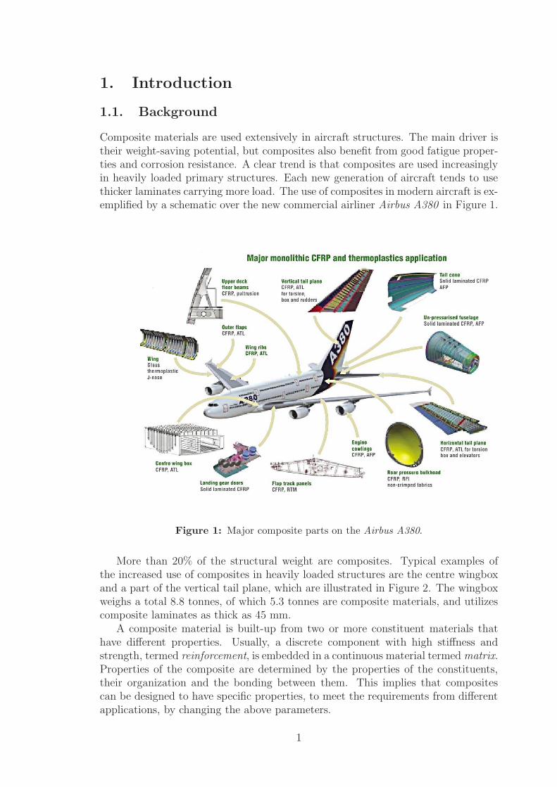
Composite materials are used extensively in aircraft structures. The main driver istheir weight-saving potential, but composites also benefit from good fatigue proper-ties and corrosion resistance. A clear trend is that composites are used increasinglyin heavily loaded primary structures. Each new generation of aircraft tends to usethicker laminates carrying more load. The use of composites in modern aircraft is ex-emplified by a schematic over the new commercial airliner Airbus A380 in Figure 1.
Figure 1: Major composite parts on the Airbus A380.
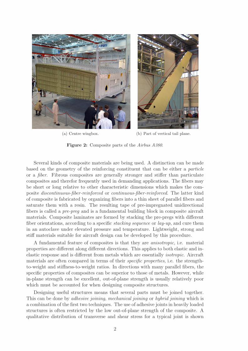
More than 20% of the structural weight are composites. Typical examples ofthe increased use of composites in heavily loaded structures are the centre wingboxand a part of the vertical tail plane, which are illustrated in Figure 2. The wingboxweighs a total 8.8 tonnes, of which 5.3 tonnes are composite materials, and utilizescomposite laminates as thick as 45 mm.
A composite material is built-up from two or more constituent materials thathave different properties. Usually, a discrete component with high stiffness andstrength, termed reinforcement, is embedded in a continuous material termed matrix.Properties of the composite are determined by the properties of the constituents,their organization and the bonding between them. This implies that compositescan be designed to have specific properties, to meet the requirements from differentapplications, by changing the above parameters.
1
(a) Centre wingbox. (b) Part of vertical tail plane.
Figure 2: Composite parts of the Airbus A380.
Several kinds of composite materials are being used. A distinction can be madebased on the geometry of the reinforcing constituent that can be either a particleor a fiber. Fibrous composites are generally stronger and stiffer than particulatecomposites and therefor frequently used in demanding applications. The fibers maybe short or long relative to other characteristic dimensions which makes the com-posite discontinuous-fiber-reinforced or continuous-fiber-reinforced. The latter kindof composite is fabricated by organizing fibers into a thin sheet of parallel fibers andsaturate them with a resin. The resulting tape of pre-impregnated unidirectionalfibers is called a pre-preg and is a fundamental building block in composite aircraftmaterials. Composite laminates are formed by stacking the pre-pregs with differentfiber orientations, according to a specific stacking sequence or lay-up, and cure themin an autoclave under elevated pressure and temperature. Lightweight, strong andstiff materials suitable for aircraft design can be developed by this procedure.
A fundamental feature of composites is that they are anisotropic, i.e. materialproperties are different along different directions. This applies to both elastic and in-elastic response and is different from metals which are essentially isotropic. Aircraftmaterials are often compared in terms of their specific properties, i.e. the strength-to-weight and stiffness-to-weight ratios. In directions with many parallel fibers, thespecific properties of composites can be superior to those of metals. However, whilein-plane strength can be excellent, out-of-plane strength is usually relatively poorwhich must be accounted for when designing composite structures.
Designing useful structures means that several parts must be joined together.This can be done by adhesive joining, mechanical joining or hybrid joining which isa combination of the first two techniques. The use of adhesive joints in heavily loadedstructures is often restricted by the low out-of-plane strength of the composite. Aqualitative distribution of transverse and shear stress for a typical joint is shown
2
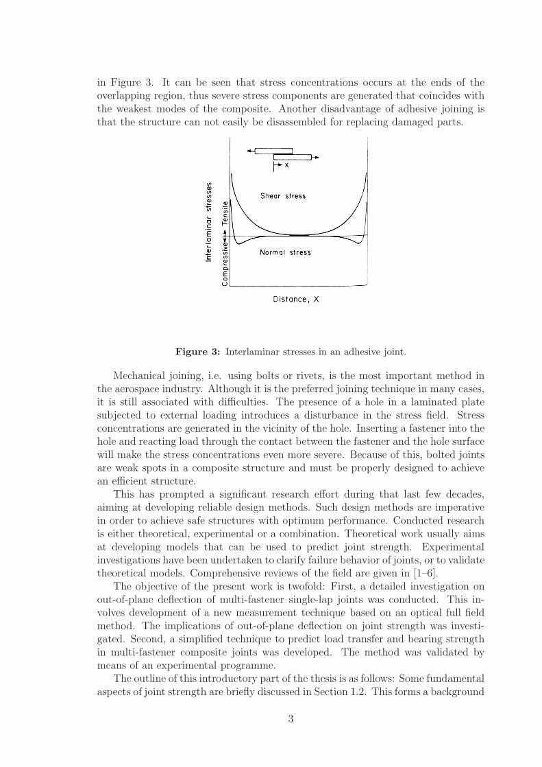
in Figure 3. It can be seen that stress concentrations occurs at the ends of theoverlapping region, thus severe stress components are generated that coincides withthe weakest modes of the composite. Another disadvantage of adhesive joining isthat the structure can not easily be disassembled for replacing damaged parts.
Figure 3: Interlaminar stresses in an adhesive joint.
Mechanical joining, i.e. using bolts or rivets, is the most important method inthe aerospace industry. Although it is the preferred joining technique in many cases,it is still associated with difficulties. The presence of a hole in a laminated platesubjected to external loading introduces a disturbance in the stress field. Stressconcentrations are generated in the vicinity of the hole. Inserting a fastener into thehole and reacting load through the contact between the fastener and the hole surfacewill make the stress concentrations even more severe. Because of this, bolted jointsare weak spots in a composite structure and must be properly designed to achievean efficient structure.
This has prompted a significant research effort during that last few decades,aiming at developing reliable design methods. Such design methods are imperativein order to achieve safe structures with optimum performance. Conducted researchis either theoretical, experimental or a combination. Theoretical work usually aimsat developing models that can be used to predict joint strength. Experimentalinvestigations have been undertaken to clarify failure behavior of joints, or to validatetheoretical models. Comprehensive reviews of the field are given in [1–6].
The objective of the present work is twofold: First, a detailed investigation onout-of-plane deflection of multi-fastener single-lap joints was conducted. This in-volves development of a new measurement technique based on an optical full fieldmethod. The implications of out-of-plane deflection on joint strength was investi-gated. Second, a simplified technique to predict load transfer and bearing strengthin multi-fastener composite joints was developed. The method was validated bymeans of an experimental programme.
The outline of this introductory part of the thesis is as follows: Some fundamentalaspects of joint strength are briefly discussed in Section 1.2. This forms a background
3
to Sections 1.3-1.4 where stresses and failure predictions are discussed, respectively.Finally, some possible future extensions to the work presented in this thesis areoutlined in Section 1.5.
1.2. Failure in composite joints
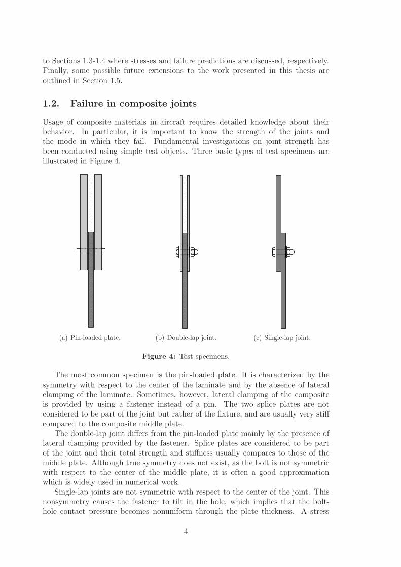
Usage of composite materials in aircraft requires detailed knowledge about theirbehavior. In particular, it is important to know the strength of the joints andthe mode in which they fail. Fundamental investigations on joint strength hasbeen conducted using simple test objects. Three basic types of test specimens areillustrated in Figure 4.
(a) Pin-loaded plate. (b) Double-lap joint. (c) Single-lap joint.
Figure 4: Test specimens.
The most common specimen is the pin-loaded plate. It is characterized by thesymmetry with respect to the center of the laminate and by the absence of lateralclamping of the laminate. Sometimes, however, lateral clamping of the compositeis provided by using a fastener instead of a pin. The two splice plates are notconsidered to be part of the joint but rather of the fixture, and are usually very stiffcompared to the composite middle plate.
The double-lap joint differs from the pin-loaded plate mainly by the presence oflateral clamping provided by the fastener. Splice plates are considered to be partof the joint and their total strength and stiffness usually compares to those of themiddle plate. Although true symmetry does not exist, as the bolt is not symmetricwith respect to the center of the middle plate, it is often a good approximationwhich is widely used in numerical work.
Single-lap joints are not symmetric with respect to the center of the joint. Thisnonsymmetry causes the fastener to tilt in the hole, which implies that the bolt-hole contact pressure becomes nonuniform through the plate thickness. A stress
4
concentration appears at the hole edge close to the shear surface of the joint. Thenonuniform forces causes the plate to bend out-of-plane which is referred to assecondary bending (SB). Different aspects related to SB are treated in Papers A-Bin this thesis.
A typical test procedure is to clamp both ends of the specimen in an hydraulictest machine and apply tensional displacement to one end while keeping the otherend fixed. The rate of the displacement is constant at a low value and the force ismonitored continously. The resulting load-displacement curve is usually nonlinearfor small loads. This is due to that the contact surface between the pin and the holeedge is growing as the load increases. At some small load, the contact surface is fullydeveloped and the load-displacement is close to linear. A small weakening effect canusually be noted, which can be attributed to nonlinear elastic properties, or to thedevelopment of small micro-mechanical damages in the material. At some high loadthe joint will fail. This can either be in an abrupt mode, which means that the jointimmediately becomes unable to carry load, or in a ductile mode. If ductile failureoccurs, the load-displacement curve will become increasingly nonlinear. However,the joint may continue to carry an increasing load before final failure.
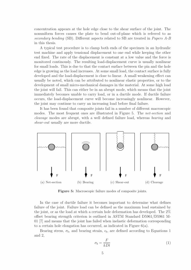
It has been found that composite joints fail in a number of different macroscopicmodes. The most frequent ones are illustrated in Figure 5. The net-section andcleavage modes are abrupt, with a well defined failure load, whereas bearing andshear-out usually are more ductile.
F
(a) Net-section
F
(b) Bearing
F
(c) Shear-out
F
(d) Cleavage
Figure 5: Macroscopic failure modes of composite joints.
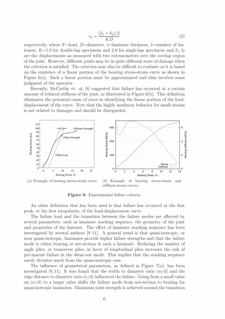
In the case of ductile failure it becomes important to determine what definesfailure of the joint. Failure load can be defined as the maximum load sustained bythe joint, or as the load at which a certain hole deformation has developed. The 2%offset bearing strength criterion is outlined in ASTM Standard D5961/D5961 M-01 [7] and means that the joint has failed when inelastic deformation correspondingto a certain hole elongation has occurred, as indicated in Figure 6(a).
Bearing stress, σb, and bearing strain, ǫb, are defined according to Equations 1and 2,
σb =F
kDt(1)
5
ǫb =(δ1 + δ2)/2
KD(2)
respectively, where F=load, D=diameter, t=laminate thickness, k=number of fas-teners, K=1.0 for double-lap specimens and 2.0 for single-lap specimens and δ1, δ2
are the displacements as measured with two extensometers over the overlap regionof the joint. However, different joints may be in quite different state of damage whenthe criterion is satisfied. The criterion may also be difficult to evaluate as it is basedon the existence of a linear portion of the bearing stress-strain curve as shown inFigure 6(a). Such a linear portion must be approximated and thus involves somejudgment of the operator.
Recently, McCarthy et. al. [8] suggested that failure has occurred at a certainamount of reduced stiffness of the joint, as illustrated in Figure 6(b). This definitioneliminates the potential cause of error in identifying the linear portion of the load-displacement of the curve. Note that the highly nonlinear behavior for small strainsis not related to damages and should be disregarded.
Offset Strength
Offset LineBea
ring
Str
ess
(ksi
)
5 10 15 20 2500
10
20
3040
5060
7080
90100
110
Ultimate Strength2%
Bearing Strain, %
(a) Example of bearing stress-strain curve.
0
200
400
600
0 2 4 6 8 10 12 140
2
4
6
Bea
ring
Str
ess
[MP
a]
Bea
ring
Stif
fnes
s [G
Pa]
Bearing Strain, %
StressStiffness
(b) Example of bearing stress-strain andstiffness-strain curves.
Figure 6: Experimental failure criteria.
An other definition that has been used is that failure has occurred at the firstpeak, or the first irregularity, of the load-displacement curve.
The failure load and the transition between the failure modes are affected byseveral parameters, such as laminate stacking sequence, the geometry of the jointand properties of the fastener. The effect of laminate stacking sequence has beeninvestigated by several authors [9–11]. A general trend is that quasi-isotropic, ornear quasi-isotropic, laminates provide higher failure strengths and that the failuremode is either bearing or net-section in such a laminate. Reducing the number ofangle plies, or transverse plies, in favor of longitudinal plies increases the risk ofpre-mature failure in the shear-out mode. This implies that the stacking sequencerarely deviates much from the quasi-isotropic case.
The influence of geometrical parameters, as defined in Figure 7(a), has beeninvestigated [9, 11]. It was found that the width to diameter ratio (w/d) and theedge distance to diameter ratio (e/d) influenced the failure. Going from a small valueon (w/d) to a larger value shifts the failure mode from net-section to bearing forquasi-isotropic laminates. Maximum joint strength is achieved around the transition
6
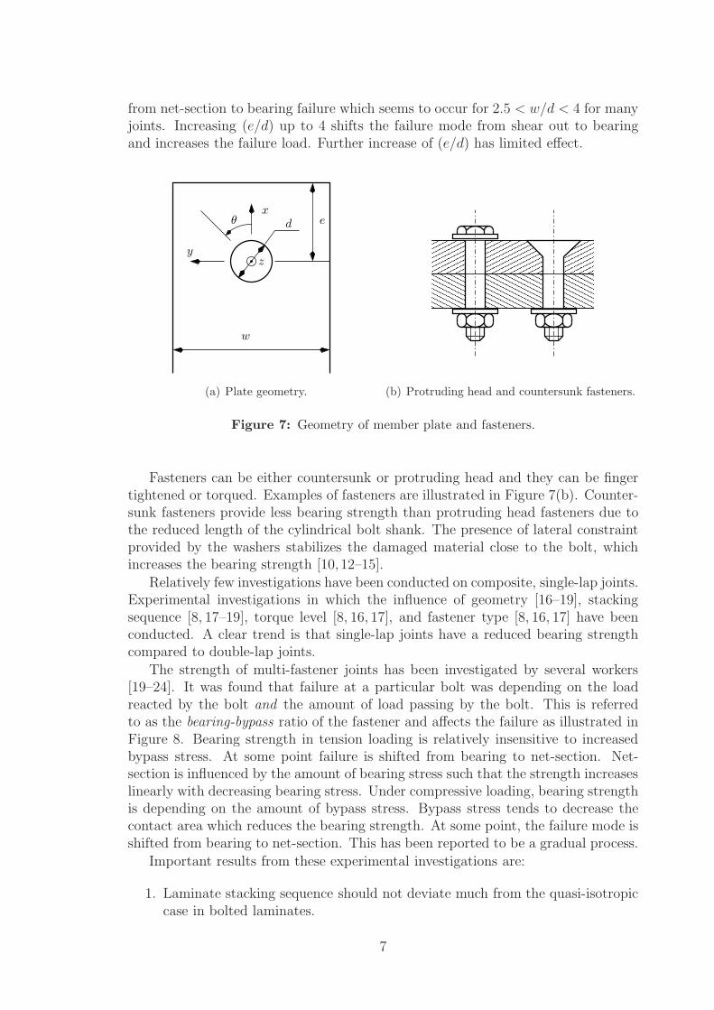
from net-section to bearing failure which seems to occur for 2.5 < w/d < 4 for manyjoints. Increasing (e/d) up to 4 shifts the failure mode from shear out to bearingand increases the failure load. Further increase of (e/d) has limited effect.
w
y
xd
z
θ e
(a) Plate geometry.
����������
����������
����������
����������
����������
����������
����������
����������
��������������������
����������������������������������������
��������������������
(b) Protruding head and countersunk fasteners.
Figure 7: Geometry of member plate and fasteners.
Fasteners can be either countersunk or protruding head and they can be fingertightened or torqued. Examples of fasteners are illustrated in Figure 7(b). Counter-sunk fasteners provide less bearing strength than protruding head fasteners due tothe reduced length of the cylindrical bolt shank. The presence of lateral constraintprovided by the washers stabilizes the damaged material close to the bolt, whichincreases the bearing strength [10, 12–15].
Relatively few investigations have been conducted on composite, single-lap joints.Experimental investigations in which the influence of geometry [16–19], stackingsequence [8, 17–19], torque level [8, 16, 17], and fastener type [8, 16, 17] have beenconducted. A clear trend is that single-lap joints have a reduced bearing strengthcompared to double-lap joints.
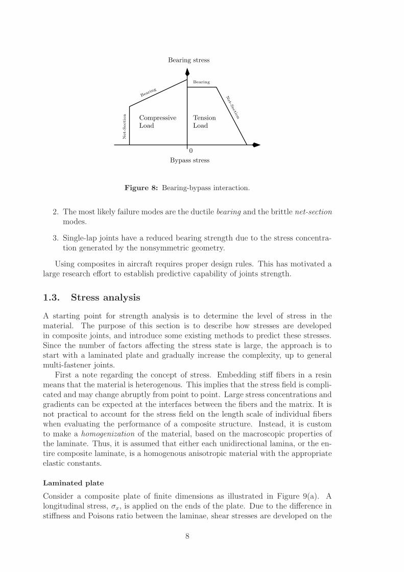
The strength of multi-fastener joints has been investigated by several workers[19–24]. It was found that failure at a particular bolt was depending on the loadreacted by the bolt and the amount of load passing by the bolt. This is referredto as the bearing-bypass ratio of the fastener and affects the failure as illustrated inFigure 8. Bearing strength in tension loading is relatively insensitive to increasedbypass stress. At some point failure is shifted from bearing to net-section. Net-section is influenced by the amount of bearing stress such that the strength increaseslinearly with decreasing bearing stress. Under compressive loading, bearing strengthis depending on the amount of bypass stress. Bypass stress tends to decrease thecontact area which reduces the bearing strength. At some point, the failure mode isshifted from bearing to net-section. This has been reported to be a gradual process.
Important results from these experimental investigations are:
1. Laminate stacking sequence should not deviate much from the quasi-isotropiccase in bolted laminates.
7
Bearing
Bearing stress
Bearin
g
Net-S
ectio
n
0
Bypass stress
Compressive TensionN
et-S
ectio
nLoad Load
Figure 8: Bearing-bypass interaction.
2. The most likely failure modes are the ductile bearing and the brittle net-sectionmodes.
3. Single-lap joints have a reduced bearing strength due to the stress concentra-tion generated by the nonsymmetric geometry.
Using composites in aircraft requires proper design rules. This has motivated alarge research effort to establish predictive capability of joints strength.
1.3. Stress analysis
A starting point for strength analysis is to determine the level of stress in thematerial. The purpose of this section is to describe how stresses are developedin composite joints, and introduce some existing methods to predict these stresses.Since the number of factors affecting the stress state is large, the approach is tostart with a laminated plate and gradually increase the complexity, up to generalmulti-fastener joints.
First a note regarding the concept of stress. Embedding stiff fibers in a resinmeans that the material is heterogenous. This implies that the stress field is compli-cated and may change abruptly from point to point. Large stress concentrations andgradients can be expected at the interfaces between the fibers and the matrix. It isnot practical to account for the stress field on the length scale of individual fiberswhen evaluating the performance of a composite structure. Instead, it is customto make a homogenization of the material, based on the macroscopic properties ofthe laminate. Thus, it is assumed that either each unidirectional lamina, or the en-tire composite laminate, is a homogenous anisotropic material with the appropriateelastic constants.
Laminated plate
Consider a composite plate of finite dimensions as illustrated in Figure 9(a). Alongitudinal stress, σx, is applied on the ends of the plate. Due to the difference instiffness and Poisons ratio between the laminae, shear stresses are developed on the
8
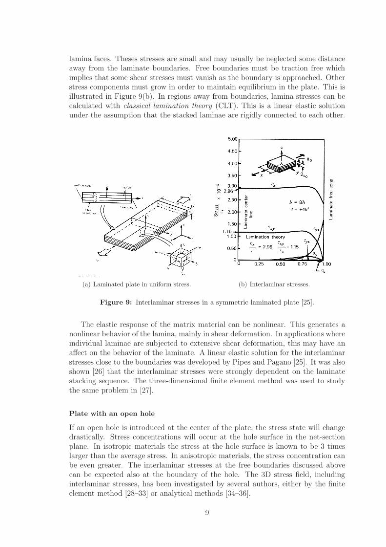
lamina faces. Theses stresses are small and may usually be neglected some distanceaway from the laminate boundaries. Free boundaries must be traction free whichimplies that some shear stresses must vanish as the boundary is approached. Otherstress components must grow in order to maintain equilibrium in the plate. This isillustrated in Figure 9(b). In regions away from boundaries, lamina stresses can becalculated with classical lamination theory (CLT). This is a linear elastic solutionunder the assumption that the stacked laminae are rigidly connected to each other.
(a) Laminated plate in uniform stress. (b) Interlaminar stresses.
Figure 9: Interlaminar stresses in a symmetric laminated plate [25].
The elastic response of the matrix material can be nonlinear. This generates anonlinear behavior of the lamina, mainly in shear deformation. In applications whereindividual laminae are subjected to extensive shear deformation, this may have anaffect on the behavior of the laminate. A linear elastic solution for the interlaminarstresses close to the boundaries was developed by Pipes and Pagano [25]. It was alsoshown [26] that the interlaminar stresses were strongly dependent on the laminatestacking sequence. The three-dimensional finite element method was used to studythe same problem in [27].
Plate with an open hole
If an open hole is introduced at the center of the plate, the stress state will changedrastically. Stress concentrations will occur at the hole surface in the net-sectionplane. In isotropic materials the stress at the hole surface is known to be 3 timeslarger than the average stress. In anisotropic materials, the stress concentration canbe even greater. The interlaminar stresses at the free boundaries discussed abovecan be expected also at the boundary of the hole. The 3D stress field, includinginterlaminar stresses, has been investigated by several authors, either by the finiteelement method [28–33] or analytical methods [34–36].
9
The large stress gradients at free edges requires special attention when numericalmethods are used. A very fine mesh at the boundary between two plies were usedby Hu et. al. [33]. Jinping and Huizu [30] developed a special finite element thatrepresented the solution analytically. This element was used close to free edges werethe regular finite elements were inadequate. Regular elements were used far awayfrom the boundaries. A substructure technique was used by Kim and Hong [31].High order elements were used by Nyman and Friberg [37] while an approach basedon spline approximations was used by Iarve [38].
The problem is simplified if the interlaminar stresses are excluded from the anal-ysis. Several workers have used the method of complex functions [39] for anisotropicplates [40] to calculate the stress field around the hole.
Pin-loaded plate
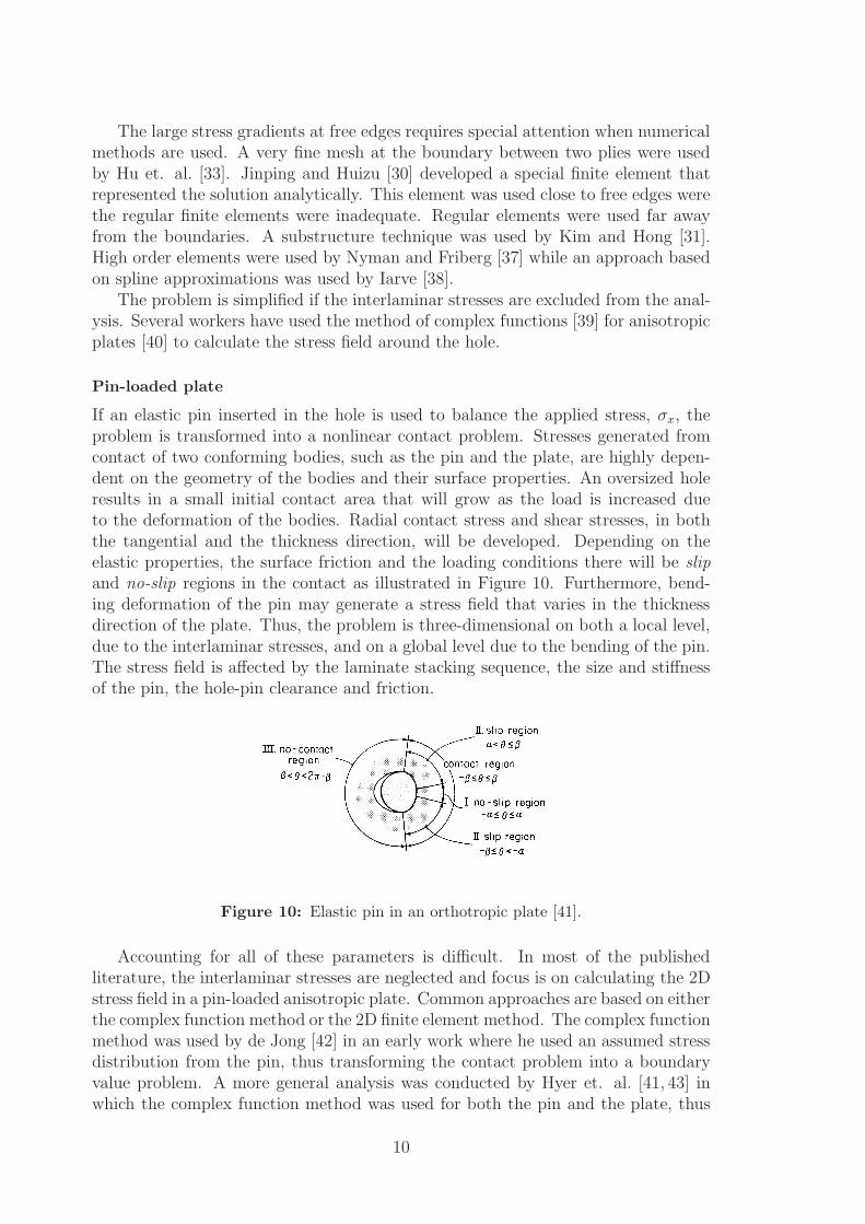
If an elastic pin inserted in the hole is used to balance the applied stress, σx, theproblem is transformed into a nonlinear contact problem. Stresses generated fromcontact of two conforming bodies, such as the pin and the plate, are highly depen-dent on the geometry of the bodies and their surface properties. An oversized holeresults in a small initial contact area that will grow as the load is increased dueto the deformation of the bodies. Radial contact stress and shear stresses, in boththe tangential and the thickness direction, will be developed. Depending on theelastic properties, the surface friction and the loading conditions there will be slipand no-slip regions in the contact as illustrated in Figure 10. Furthermore, bend-ing deformation of the pin may generate a stress field that varies in the thicknessdirection of the plate. Thus, the problem is three-dimensional on both a local level,due to the interlaminar stresses, and on a global level due to the bending of the pin.The stress field is affected by the laminate stacking sequence, the size and stiffnessof the pin, the hole-pin clearance and friction.
Figure 10: Elastic pin in an orthotropic plate [41].
Accounting for all of these parameters is difficult. In most of the publishedliterature, the interlaminar stresses are neglected and focus is on calculating the 2Dstress field in a pin-loaded anisotropic plate. Common approaches are based on eitherthe complex function method or the 2D finite element method. The complex functionmethod was used by de Jong [42] in an early work where he used an assumed stressdistribution from the pin, thus transforming the contact problem into a boundaryvalue problem. A more general analysis was conducted by Hyer et. al. [41, 43] inwhich the complex function method was used for both the pin and the plate, thus
10
accounting for deformation of both parts. The contact problem was solved by meansof the collocation method where the slip and no-slip regions were identified in aniterative process. The 2D finite element method has been used extensively for thisproblem [44–51]. In most cases the analyses are straightforward and will not bediscussed further. The nonlinear stress-strain relation in shear mode of each laminawas accounted for by Serabian [52] and Shokrieh et. al. [53,54] in 3D analyses, andby several authors [49, 55–59] in 2D analyses. This material behavior is known tobe specially important for angle-ply and cross-ply laminates.
Double-lap joint
A pin-loaded plate is a laboratory test specimen rather than a real joint. If twosplice plates are added, and the pin is replaced by a bolt with washers and a nut, arealistic double-lap joint is created. The main difference from the pin-loaded plateis that compressive stresses in the thickness direction is generated when torque isapplied to the fastener. The plates are thus pressed together which means thatsome load is transferred by friction between the plates instead of by the bolt-holecontact. The compressive stresses in the thickness direction and the friction betweenthe plates increase the 3D nature of the problem.
Some workers focused on calculating the interlaminar stresses while leaving outother parameters such as friction and pin elasticity. A special composite finiteelement was developed by Wong and Matthews [60] which allowed for calculationsof interlaminar stresses in laminates consisting of a few plies. More complete 3DFE-analyses taking more parameters into account, including interlaminar stresses,friction, pin-elasticity, clamping and clearance have also been conducted [61–64].
Single-lap joint
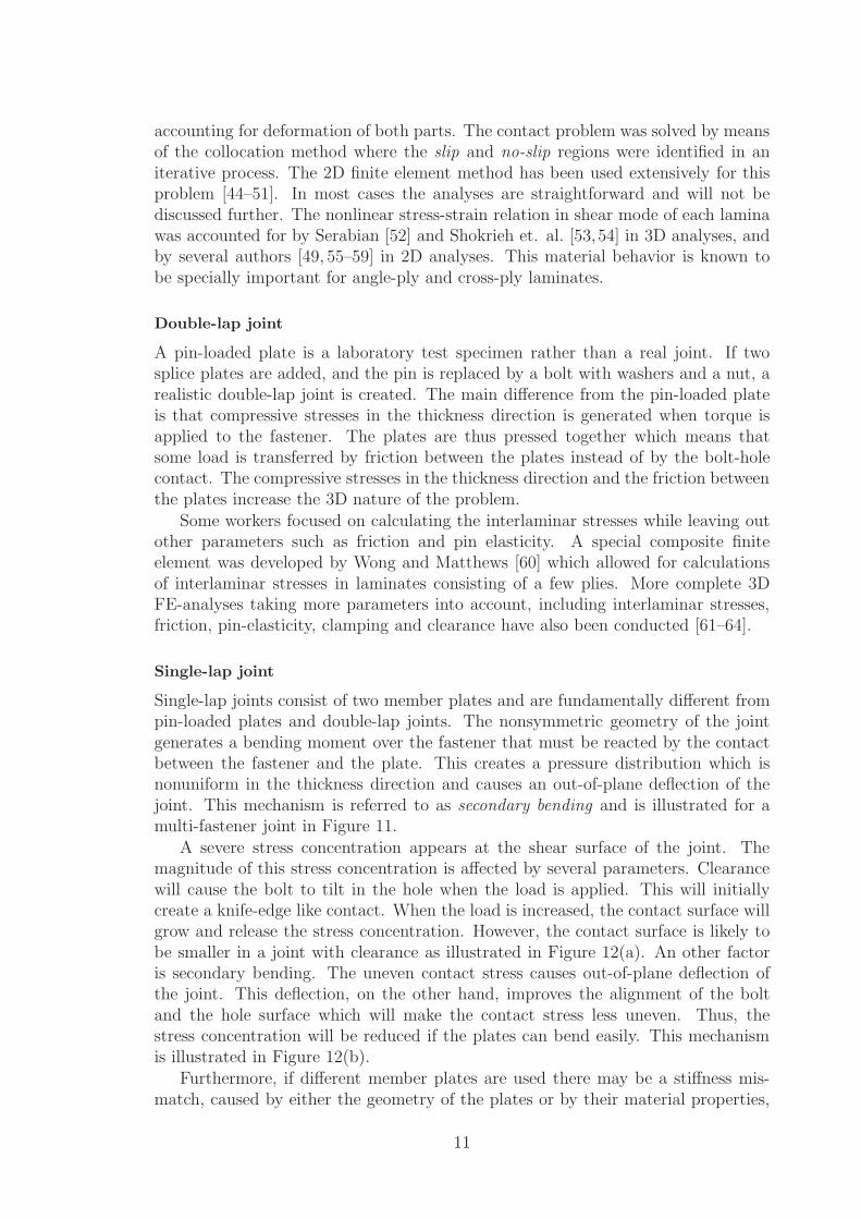
Single-lap joints consist of two member plates and are fundamentally different frompin-loaded plates and double-lap joints. The nonsymmetric geometry of the jointgenerates a bending moment over the fastener that must be reacted by the contactbetween the fastener and the plate. This creates a pressure distribution which isnonuniform in the thickness direction and causes an out-of-plane deflection of thejoint. This mechanism is referred to as secondary bending and is illustrated for amulti-fastener joint in Figure 11.
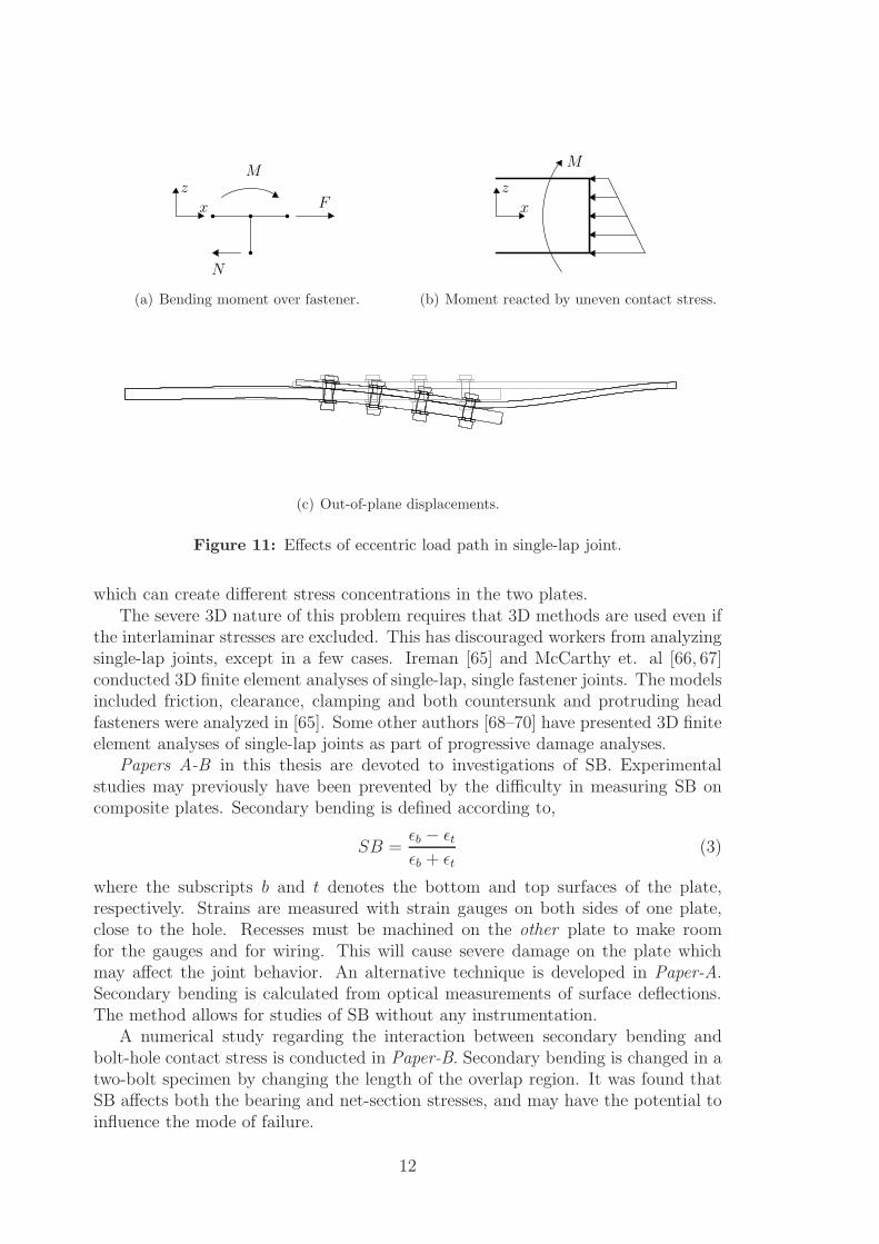
A severe stress concentration appears at the shear surface of the joint. Themagnitude of this stress concentration is affected by several parameters. Clearancewill cause the bolt to tilt in the hole when the load is applied. This will initiallycreate a knife-edge like contact. When the load is increased, the contact surface willgrow and release the stress concentration. However, the contact surface is likely tobe smaller in a joint with clearance as illustrated in Figure 12(a). An other factoris secondary bending. The uneven contact stress causes out-of-plane deflection ofthe joint. This deflection, on the other hand, improves the alignment of the boltand the hole surface which will make the contact stress less uneven. Thus, thestress concentration will be reduced if the plates can bend easily. This mechanismis illustrated in Figure 12(b).
Furthermore, if different member plates are used there may be a stiffness mis-match, caused by either the geometry of the plates or by their material properties,
11
x
zM
F
N
(a) Bending moment over fastener.
x
z
M
(b) Moment reacted by uneven contact stress.
(c) Out-of-plane displacements.
Figure 11: Effects of eccentric load path in single-lap joint.
which can create different stress concentrations in the two plates.The severe 3D nature of this problem requires that 3D methods are used even if
the interlaminar stresses are excluded. This has discouraged workers from analyzingsingle-lap joints, except in a few cases. Ireman [65] and McCarthy et. al [66, 67]conducted 3D finite element analyses of single-lap, single fastener joints. The modelsincluded friction, clearance, clamping and both countersunk and protruding headfasteners were analyzed in [65]. Some other authors [68–70] have presented 3D finiteelement analyses of single-lap joints as part of progressive damage analyses.
Papers A-B in this thesis are devoted to investigations of SB. Experimentalstudies may previously have been prevented by the difficulty in measuring SB oncomposite plates. Secondary bending is defined according to,
SB =ǫb − ǫt
ǫb + ǫt
(3)
where the subscripts b and t denotes the bottom and top surfaces of the plate,respectively. Strains are measured with strain gauges on both sides of one plate,close to the hole. Recesses must be machined on the other plate to make roomfor the gauges and for wiring. This will cause severe damage on the plate whichmay affect the joint behavior. An alternative technique is developed in Paper-A.Secondary bending is calculated from optical measurements of surface deflections.The method allows for studies of SB without any instrumentation.
A numerical study regarding the interaction between secondary bending andbolt-hole contact stress is conducted in Paper-B. Secondary bending is changed in atwo-bolt specimen by changing the length of the overlap region. It was found thatSB affects both the bearing and net-section stresses, and may have the potential toinfluence the mode of failure.
12
No clearance
Clearance
σ
σ
(a) Clearance
No secondary bending
Secondary bending
σ
σ
(b) Secondary bending
Figure 12: Effect of clearance and secondary bending on the contact stress.
Multi-fastener joint
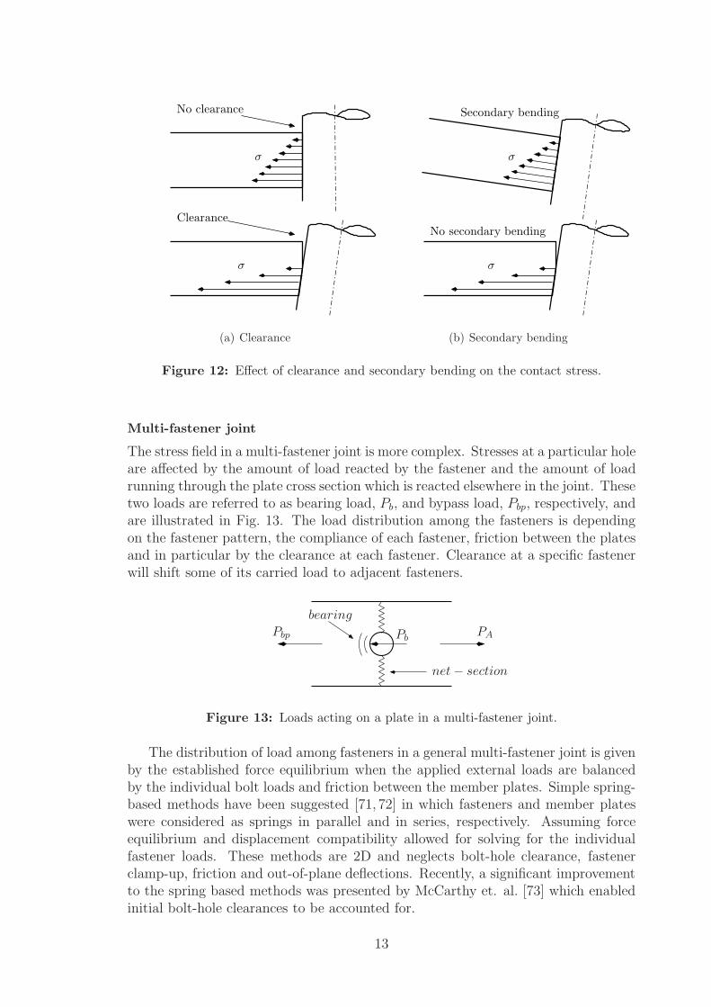
The stress field in a multi-fastener joint is more complex. Stresses at a particular holeare affected by the amount of load reacted by the fastener and the amount of loadrunning through the plate cross section which is reacted elsewhere in the joint. Thesetwo loads are referred to as bearing load, Pb, and bypass load, Pbp, respectively, andare illustrated in Fig. 13. The load distribution among the fasteners is dependingon the fastener pattern, the compliance of each fastener, friction between the platesand in particular by the clearance at each fastener. Clearance at a specific fastenerwill shift some of its carried load to adjacent fasteners.
PAPbPbp
bearing
net − section
Figure 13: Loads acting on a plate in a multi-fastener joint.
The distribution of load among fasteners in a general multi-fastener joint is givenby the established force equilibrium when the applied external loads are balancedby the individual bolt loads and friction between the member plates. Simple spring-based methods have been suggested [71, 72] in which fasteners and member plateswere considered as springs in parallel and in series, respectively. Assuming forceequilibrium and displacement compatibility allowed for solving for the individualfastener loads. These methods are 2D and neglects bolt-hole clearance, fastenerclamp-up, friction and out-of-plane deflections. Recently, a significant improvementto the spring based methods was presented by McCarthy et. al. [73] which enabledinitial bolt-hole clearances to be accounted for.
13
Baumann [74] used structural finite elements, i.e. beams and shells, to representthe fasteners and the plates. This approach was further refined by Oakeshott andMatthews [75] in a study on composite double shear joints where composite shellelements were used to model the plates. A more advanced approach was presentedby Friberg [76] in which each fastener was represented by a macro element that wasplaced in square cut-outs in the structure. The macro element was built up fromshell elements, beam elements, gap elements and multiple point constraints thatrepresented the plates, the fastener, the fastener-hole contact and the plate-platecontact, respectively.
The above methods, with the exception of Fribergs method, are devoted to cal-culating the load distribution. No information about the stresses in the plates, suchas contact stresses or the interlaminar stresses, is obtained. Furthermore, importantparameters are omitted from the analyses, including clearance, friction and clamp-ing. A range of 2D analyses, similar to the analyses conducted for pin-joints andsingle fastener joints described above, have been reported. Methods are based onthe 2D finite element method [77–83] or on the method of complex functions [84–86].
Relatively few 3D analyses have been reported on multi-fastener joints. Mc-Carthy and McCarthy [87] developed 3D FE-models based on continuum elementsand investigated the influence of bolt-hole clearance on load distribution in single-lap joints with three fasteners arranged in a single column. Good agreement withexperiments was found. A sophisticated method capable of efficiently solving thegeneral 3D contact problem for joints with a large number of fasteners was developedby Andersson [88, 89]. The complete global problem needs only to be solved onceand subsequent solutions, with modified fastener locations, can be achieved from theglobal solution at significantly reduced computational cost compared to the globalsolution itself. This enables the method to be used in parametric and optimizationstudies which was done for a single-lap joint with 20 fasteners. Friction was nottaken into account.
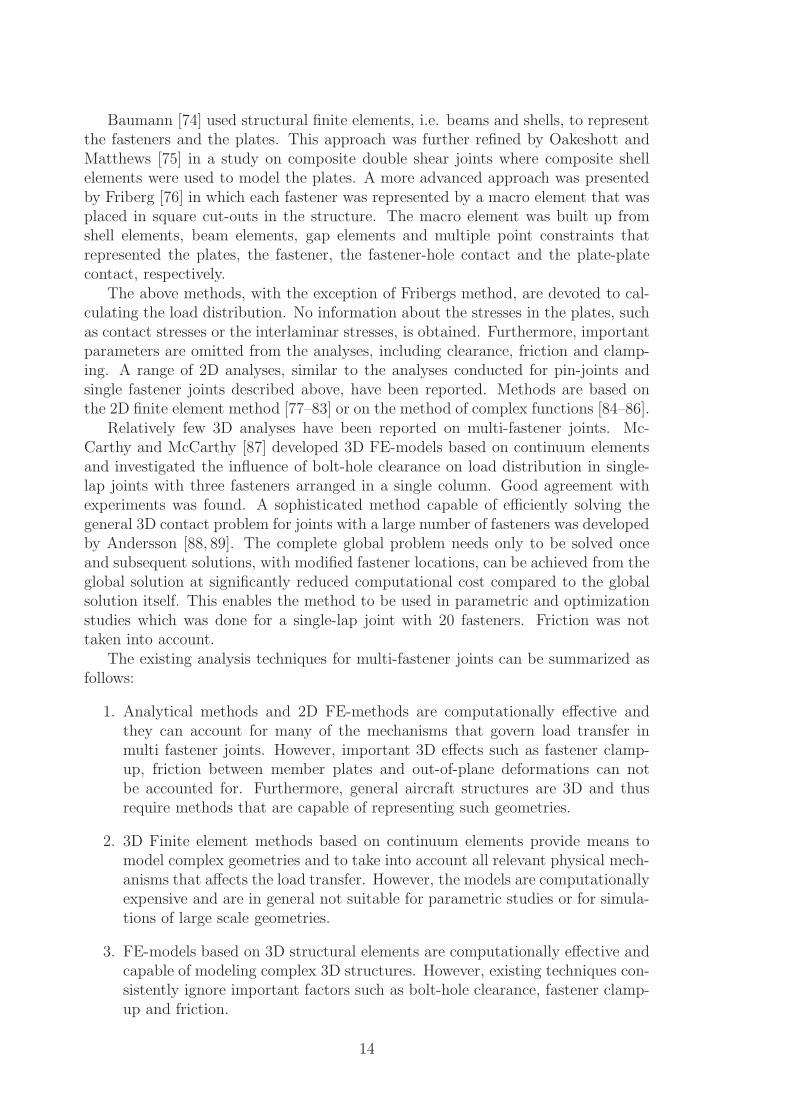
The existing analysis techniques for multi-fastener joints can be summarized asfollows:
1. Analytical methods and 2D FE-methods are computationally effective andthey can account for many of the mechanisms that govern load transfer inmulti fastener joints. However, important 3D effects such as fastener clamp-up, friction between member plates and out-of-plane deformations can notbe accounted for. Furthermore, general aircraft structures are 3D and thusrequire methods that are capable of representing such geometries.
2. 3D Finite element methods based on continuum elements provide means tomodel complex geometries and to take into account all relevant physical mech-anisms that affects the load transfer. However, the models are computationallyexpensive and are in general not suitable for parametric studies or for simula-tions of large scale geometries.
3. FE-models based on 3D structural elements are computationally effective andcapable of modeling complex 3D structures. However, existing techniques con-sistently ignore important factors such as bolt-hole clearance, fastener clamp-up and friction.
14
It appears that a method that is computationally effective and capable of ac-counting for all important parameters is missing. Part of the work in this thesis isdevoted to developing such a method. The approach is to develop a detailed 3Dcontinuum finite element model of a multi-fastener joint that is capable of account-ing for all parameters that significantly affect the load distribution. The model isverified by experimentally determined fastener loads. A parametric study is thenconducted in order to investigate the importance of different parameters. This workis reported in Paper-C in this thesis.
Based on the results in Paper-C, a simplified FE-model based on structural ele-ments is developed. Clearance, friction and fastener clamp-up is modeled by meansof special purpose connector elements. The model is verified through comparisonswith the detailed model developed in Paper-C. This work is reported in Paper-D inthis thesis.
1.4. Strength prediction
Once the stresses are calculated, they can be used in strength analysis. Thus, stressesare evaluated with respect to some failure criterion. A large number of criteria havebeen developed, usually postulating that the material will fail at a certain level ofstress or strain. Using such a criterion to determine the strength of a joint requiresthat it is used in conjunction with a failure hypothesis. A simple hypothesis wouldbe that the joint has failed when the criterion is fulfilled at any point in the laminate.This leads to conservative predictions for joints. More sophisticated hypotheses havebeen developed, e.g. that joint failure occurs when the criterion is satisfied at certainstrategic locations or over a certain volume.
In this section, some widely used criteria and hypotheses are introduced. It isconvenient to distinguish between criteria for the laminate, the lamina, delaminationand micro-mechanical failures in the composite.
Laminate based criteria
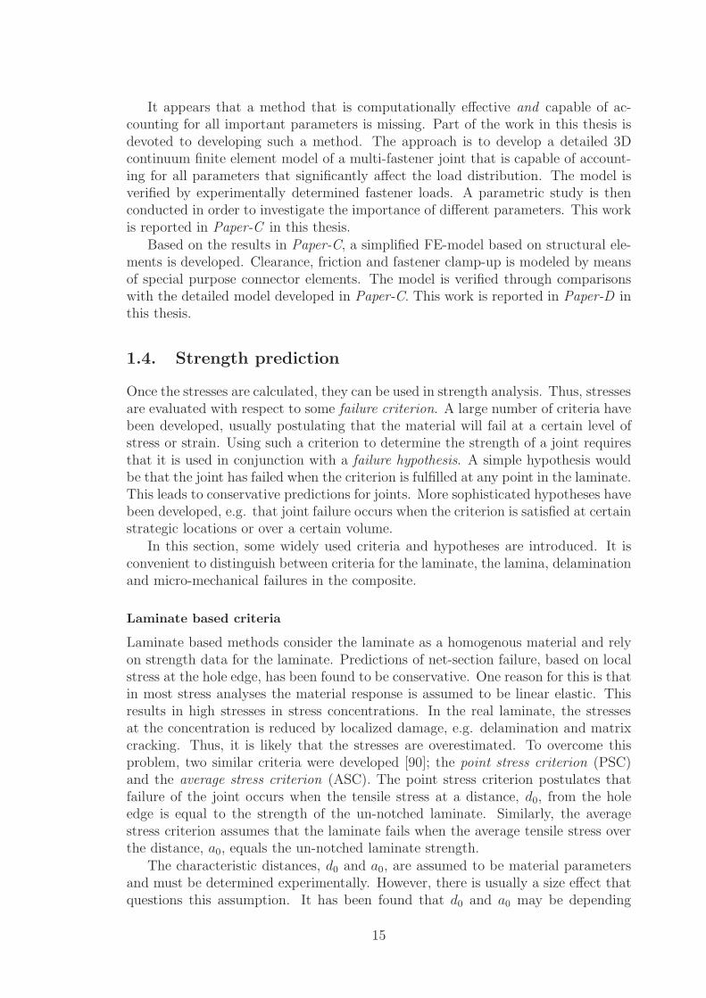
Laminate based methods consider the laminate as a homogenous material and relyon strength data for the laminate. Predictions of net-section failure, based on localstress at the hole edge, has been found to be conservative. One reason for this is thatin most stress analyses the material response is assumed to be linear elastic. Thisresults in high stresses in stress concentrations. In the real laminate, the stressesat the concentration is reduced by localized damage, e.g. delamination and matrixcracking. Thus, it is likely that the stresses are overestimated. To overcome thisproblem, two similar criteria were developed [90]; the point stress criterion (PSC)and the average stress criterion (ASC). The point stress criterion postulates thatfailure of the joint occurs when the tensile stress at a distance, d0, from the holeedge is equal to the strength of the un-notched laminate. Similarly, the averagestress criterion assumes that the laminate fails when the average tensile stress overthe distance, a0, equals the un-notched laminate strength.
The characteristic distances, d0 and a0, are assumed to be material parametersand must be determined experimentally. However, there is usually a size effect thatquestions this assumption. It has been found that d0 and a0 may be depending
15
on the size of the hole. A large hole means a larger volume of highly stressedmaterial, compared to the case of a small hole. Larger volume, in turn, implieshigher probability that the material contains a large flaw that leads to failure. Thisphenomenon will affect the real strength of the laminate and thus affect d0 and a0.Pipes et. al. [91] proposed a relation between the hole radius and the characteristicdimensions in order to overcome this problem. More examples of prediction methodsrelated to PSC can be found in [92, 93].
Another category of laminate based methods is the fracture mechanics basedapproach. Waddoups et. al [94] applied linear elastic fracture mechanics (LEFM)to predict strength of composite plates with an open hole. They assumed an energy-intense region of length a to exist at the hole edge. The stress at which fractureoccurs is expressed in terms of the characteristic length a, the hole radius and thefracture toughness of the composite. The PSC, ASC and the above LEFM approachall depend on characteristic dimensions that must be determined experimentally.Backlund [95] developed a method that only requires basic stiffness and fracture datafor the laminate. He suggested that the fictitious crack model (FCM), previouslyused for failure analysis of concrete, be used to represent the development of damagein the laminate. A fictitious crack was assumed in the high stress region where thestresses are larger than the un-notched strength. The cohesive forces acting on thecrack surfaces depends on the crack opening and reduces to zero at some pointbehind the crack tip. The distance from the hole edge to this point was assumed torepresent the length of a real crack. This enabled the modeling of crack growth andthe failure load was taken to be the load where the crack propagation turns unstable.Several other authors have presented failure predictions of composite joints basedon fracture mechanics [96–98].
Lamina based criteria
Lamina based methods are based on strength data for the unidirectional lamina usedin the laminate. The advantage compared to laminate based methods is that oncethe strength data for the lamina has been experimentally determined, failure can bepredicted for arbitrary stacking sequences. A disadvantage is that stresses need tobe calculated in each lamina, compared to the laminate based methods which onlyrequires stresses for the homogenized plate.
Typically, a stress (or strain) envelope in 2D or 3D is assumed to define failureof the lamina. Lamina criteria can be used either to predict the first failure of anylamina, so called first-ply failure, or to calculate the failure of the entire laminate,so called last-ply failure. In the latter case, stresses are calculated in all laminaeand the criterion is applied for each lamina. Laminae that fails are excluded fromthe analysis and a new stress state is calculated. This process is repeated until alllaminae have failed.
The Tsai-Wu criterion [99] assumes the existence of a failure surface, f(σk), inthe three dimensional stress space that can be expressed as
f(σk) = Fiσi + Fijσiσj = 1 (4)
where σi are components of the stress tensor, Fi and Fij are strength tensors,i, j, k = 1 . . . 6 and the Einstein summation convention is used. It is assumed that
16
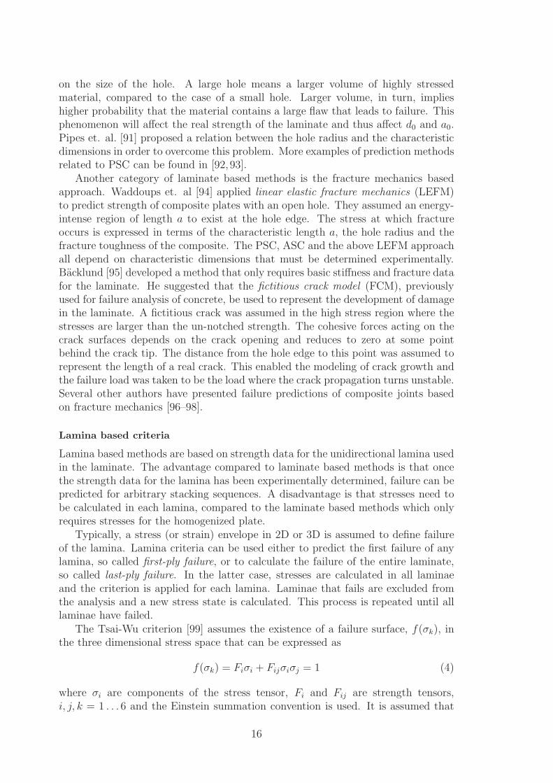
the strength tensors, Fi and Fij, are symmetric in accordance with the stress tensor,and the elastic compliance tensor, which implies that the number of independententries in the tensors are 6 and 21, respectively, for a general anisotropic material.Further symmetry in the material reduces the number of entries in the strength ten-sors in analogy with the reduction of entries in the compliance matrix. All non-zeroentries must be determined through a series of uni-axial and bi-axial tests. Thelinear terms, Fi, implies that the different strengths in tension and compression ofa composite is accounted for. The quadratic terms, Fij, defines an elliptic failuresurface in the stress space where the sensitivity to multi-axial stresses is capturedwhen i 6= j. Similar criteria were developed by several authors [2]. Most of themare simpler and requires fewer material parameters. The criterion developed byHoffman [100] has been used in many studies to predict strength of joints.
A simpler, in-plane quadratic criterion, suggested by Yamada and Sun [101] hasbeen used extensively for bolted joints. It involves only two material parametersand is defined according to
(
σ1
X
)2
+
(
τ12
S12
)2
= 1 (5)
where X and S12 are the longitudinal ply strength and the ply shear strength,respectively. The absence of linear terms implies that the material is assumed tohave equal strength in tension and compression.
Maximum stress, Maximum strain and the Distortional energy criteria were usedby Waszczak and Cruse [102] in an early study. Each criterion was used with thesimple hypothesis that a pin-joint would fail when the criterion was satisfied in thevicinity of the hole. This proved to be conservative in most cases.
Soni [103] used the Hoffman criterion [100] in conjunction with a more advancedfailure hypothesis. The 2D stress components from the stress analysis were used inthe criterion to calculate the maximum average bearing stress that could be carriedby each lamina. The lamina capable of sustaining the highest stress was consideredto be the strongest lamina. Ultimate failure of the joint was assumed to occurwhen the strongest lamina failed. Laminae failing prior to ultimate failure were notremoved from the analysis, i.e. no stiffness reduction of the laminate due to localizeddamage was accounted for. This method still proved to be conservative.
Improved accuracy was achieved in a method suggested by Chang, Scott andSpringer [11]. The Yamada-Sun criterion [101] was used with a failure hypothesisthat can be considered as an extension of the laminate based point stress criterion. Acharacteristic curve was constructed from R0t and R0c which denotes characteristiclength in the net-section and bearing plane, respectively. Thus R0t is identical to d0
that was used in [90]. Such a curve is illustrated in Figure 14. The failure criterionis evaluated along the characteristic curve and the joint was considered to fail whenthe criterion was satisfied for any lamina, i.e. it is a first-ply failure prediction. Thelocation on the curve where failure was predicted determines the failure mode to berespectively, bearing, shear-out and net-section according to
−15◦ 6 θ 6 15◦
30◦ 6 θ 6 60◦
75◦ 6 θ 6 90◦.
17
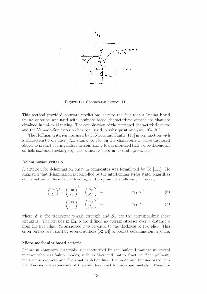
Figure 14: Characteristic curve [11].
This method provided accurate predictions despite the fact that a lamina basedfailure criterion was used with laminate based characteristic dimensions that areobtained in uni-axial testing. The combination of the proposed characteristic curveand the Yamada-Sun criterion has been used in subsequent analyses [104–109].
The Hoffman criterion was used by DiNicola and Fantle [110] in conjunction witha characteristic distance, dfe, similar to R0c on the characteristic curve discussedabove, to predict bearing failure in a pin-joint. It was proposed that dfe be dependenton hole size and stacking sequence which resulted in accurate predictions.
Delamination criteria
A criterion for delamination onset in composites was formulated by Ye [111]. Hesuggested that delamination is controlled by the interlaminar stress state, regardlessof the nature of the external loading, and proposed the following criterion,
(σ33
Z
)2
+
(
τ13
S13
)2
+
(
τ23
S23
)2
= 1 σ33 > 0 (6)
(
τ13
S13
)2
+
(
τ23
S23
)2
= 1 σ33 < 0 (7)
where Z is the transverse tensile strength and Sij are the corresponding shearstrengths. The stresses in Eq. 6 are defined as average stresses over a distance cfrom the free edge. Ye suggested c to be equal to the thickness of two plies. Thiscriterion has been used by several authors [62–64] to predict delamination in joints.
Micro-mechanics based criteria
Failure in composite materials is characterized by accumulated damage in severalmicro-mechanical failure modes, such as fiber and matrix fracture, fiber pull-out,matrix micro-cracks and fiber-matrix debonding. Laminate and lamina based fail-ure theories are extensions of theories developed for isotropic metals. Therefore
18
they are not closely related to the actual physical mechanisms occurring in the ma-terial. They all have in common that they predict the complete failure of the entirelaminate or lamina. No distinction is made between the different micro-mechanicalfailure modes, and the laminate or lamina is typically assumed to have zero stiffnessafter failure. An approach closer related to the actual physics involved, is to pre-dict the micro-mechanical mode of failure and change the macroscopic properties ofthe lamina based on this prediction. Such progressive damage analyses have beenconducted by several authors [12, 14, 53, 55–59,69, 70, 112–115].
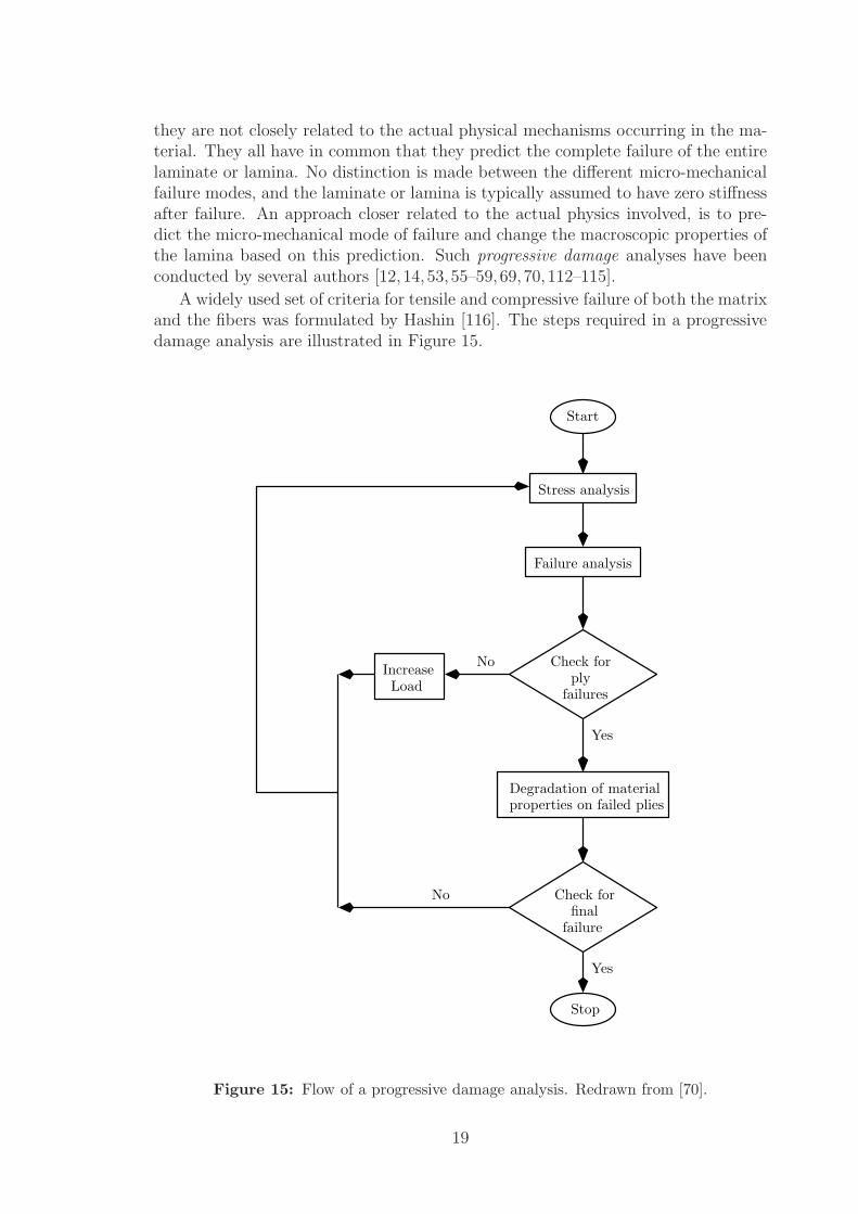
A widely used set of criteria for tensile and compressive failure of both the matrixand the fibers was formulated by Hashin [116]. The steps required in a progressivedamage analysis are illustrated in Figure 15.
No
Yes
No
Stop
Yes
properties on failed pliesDegradation of material
Failure analysis
Stress analysis
LoadIncrease
Check for
failuresply
Check forfinal
failure
Start
Figure 15: Flow of a progressive damage analysis. Redrawn from [70].
19
Progressive damage analyses are important in order to understand the failureprocess and to calculate the maximum load capacity of a joint under an overloadsituation. However, such analyses are complicated and computationally expensive.From a design point of view it is also important to maximize the load capacity ofthe joint with respect to the introduction of damages. Thus it becomes importantto know what is the initial mode of failure and how can it be predicted. This isparticularly so for the macroscopic bearing mode. It is well known that damagesmay be introduced well before the ultimate failure of the joint.
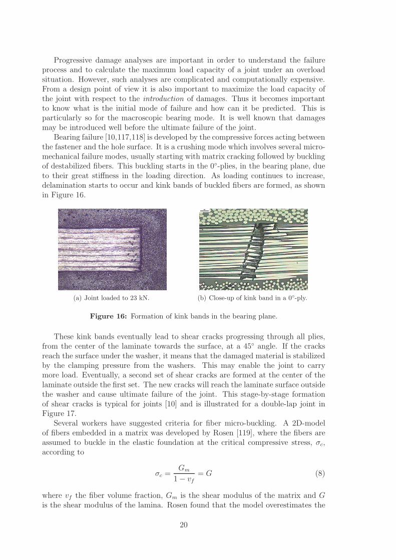
Bearing failure [10,117,118] is developed by the compressive forces acting betweenthe fastener and the hole surface. It is a crushing mode which involves several micro-mechanical failure modes, usually starting with matrix cracking followed by bucklingof destabilized fibers. This buckling starts in the 0◦-plies, in the bearing plane, dueto their great stiffness in the loading direction. As loading continues to increase,delamination starts to occur and kink bands of buckled fibers are formed, as shownin Figure 16.
(a) Joint loaded to 23 kN. (b) Close-up of kink band in a 0◦-ply.
Figure 16: Formation of kink bands in the bearing plane.
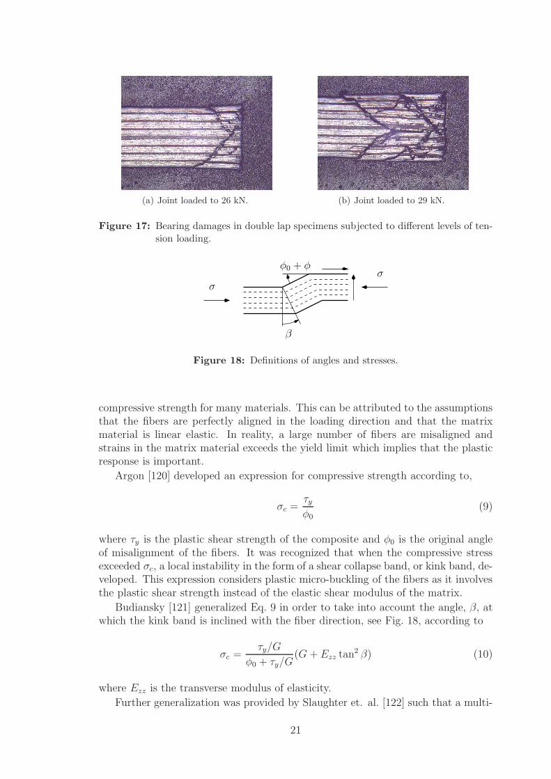
These kink bands eventually lead to shear cracks progressing through all plies,from the center of the laminate towards the surface, at a 45◦ angle. If the cracksreach the surface under the washer, it means that the damaged material is stabilizedby the clamping pressure from the washers. This may enable the joint to carrymore load. Eventually, a second set of shear cracks are formed at the center of thelaminate outside the first set. The new cracks will reach the laminate surface outsidethe washer and cause ultimate failure of the joint. This stage-by-stage formationof shear cracks is typical for joints [10] and is illustrated for a double-lap joint inFigure 17.
Several workers have suggested criteria for fiber micro-buckling. A 2D-modelof fibers embedded in a matrix was developed by Rosen [119], where the fibers areassumed to buckle in the elastic foundation at the critical compressive stress, σc,according to
σc =Gm
1 − vf
= G (8)
where vf the fiber volume fraction, Gm is the shear modulus of the matrix and Gis the shear modulus of the lamina. Rosen found that the model overestimates the
20
(a) Joint loaded to 26 kN. (b) Joint loaded to 29 kN.
Figure 17: Bearing damages in double lap specimens subjected to different levels of ten-sion loading.
β
σσ
φ0 + φ
Figure 18: Definitions of angles and stresses.
compressive strength for many materials. This can be attributed to the assumptionsthat the fibers are perfectly aligned in the loading direction and that the matrixmaterial is linear elastic. In reality, a large number of fibers are misaligned andstrains in the matrix material exceeds the yield limit which implies that the plasticresponse is important.
Argon [120] developed an expression for compressive strength according to,
σc =τy
φ0
(9)
where τy is the plastic shear strength of the composite and φ0 is the original angleof misalignment of the fibers. It was recognized that when the compressive stressexceeded σc, a local instability in the form of a shear collapse band, or kink band, de-veloped. This expression considers plastic micro-buckling of the fibers as it involvesthe plastic shear strength instead of the elastic shear modulus of the matrix.
Budiansky [121] generalized Eq. 9 in order to take into account the angle, β, atwhich the kink band is inclined with the fiber direction, see Fig. 18, according to
σc =τy/G
φ0 + τy/G(G + Ezz tan2 β) (10)
where Ezz is the transverse modulus of elasticity.
Further generalization was provided by Slaughter et. al. [122] such that a multi-
21
axial stress state was accounted for according to
σc =ατy − τxz − σzz tan β
φ0 + φ(11)
α =
√
1 +
(
σzzy
τy
)2
tan2 β (12)
where σzzyis the transverse yield strength and φ is the additional rotation of fibers
within the kink band.This micro-buckling criterion is 2D in the sense that the width of the material
is not accounted for. To the best of the authors knowledge, it has not been used topredict strength of bolted joints. In Paper-E in this thesis, the criterion is used inconjunction with a simple FE-model and a failure hypothesis to predict strength ofa multi-fastener single-lap joint. The FE-model is based on structural elements andcalculates the load distribution while accounting for clearances, clamping, frictionand secondary bending. Bolt-hole contact stresses are obtained from simple forceand moment equilibrium equations, and assumptions regarding the stress distribu-tion in the thickness and circumferential directions. The failure hypothesis is thatthe joint has failed when the criterion is fulfilled in the most highly stressed lamina,in the joint bearing plane, of the most heavily loaded fastener. This is assumed tocorrespond to the first irregularity in experimental load-displacement curves.
1.5. Future work
The use of composite materials in aircraft is steadily growing. Still, the full weight-saving potential of such materials may not be reached due to suboptimal design ofthe joints. There is a constant need for improved design methods, both on a globallevel and on a local level.
On the global level, joints are limiting factors of the entire structure. The behav-ior of the joints should be accounted for as early as possible in the design process.Finding optimum bolt patterns is vital to the final performance of the structure.This requires effective, accurate predictions of load distribution and strength inlarge scale structures with many bolts. The ability to use such predictions in opti-mization routines may improve the overall design. Statistical analyses of “missingbolt” or “worst case clearance” scenarios may increase the ability to design fail safestructures. A starting point for such a method is presented in Papers D-E in thisthesis. For industrial use, the method should be extended to use shell elements torepresent the plates, to enable modeling of complicated structures. Further exten-sions could be to use a more sophisticated procedure to calculate the stresses, basedon the forces and moments calculated in the FE-model, and to apply several failurecriteria to predict other modes of failure.
On the local level, strength prediction of critical fasteners remains an issue. De-spite large efforts in this field, accurate and fully reliable methods are not available.This results in conservative designs with a weight penalty. While semi-empiricalmethods and laminate- and lamina based methods continues to play important roles
22
in todays design procedure, methods based on micro-mechanical mechanisms seemmore promising in terms of improved accuracy in predictions. This should be re-flected in future research activities within this field.
References
[1] E. W. Godwin and F. L. Matthews. Review of the strengths of joints in fibre-reinforcedplastics: Part1 Mechanically fastened joints. Composites, 11(3):155–160, 1980.
[2] R. E. Rowlands. Strength (failure) theories and their experimental correlation. In G. C.Sih and A. M. Skudra, editors, Handbook of Composites, volume 3 - Failure Mechanics ofComposites, pages 71–125. Elsevier, Amsterdam, 1985.
[3] C. Poon. Literature review on the design of composite mechanically fastened joints. Tech-nical Report AENOE5, National Aeronautical Establishment, National Research Counsil,Canada, 1986.
[4] M. N. Nahas. Survey of failure and post-failure theories of laminated fiber-reinforced com-posites. J. Comp. Tech. Res., 8(4):138–153, 1986.
[5] D. W. Oplinger. Bolted joints in composite structures - An overview. In AGARD Conference
proceedings No. 590, Florence, Italy, September 1996.
[6] P. P. Camanho and F. L. Matthews. Stress analysis and strength prediction of mechanicallyfasteners joints in FRP: a review. Composites Part A, 28A:529–547, 1997.
[7] Standard test method for bearing response of polymer matrix composite laminates, 2001.ASTM Standard D 5961/D 5961M-01.
[8] M. A. McCarthy, V. P. Lawlor, W. F. Stanley, and C. T. McCarthy. Bolt-hole clearanceeffects and strength criteria in single-bolt, single-lap, composite bolted joints. Composites
Science and Technology, 62:1415–1431, 2002.
[9] L. J. Hart-Smith. Bolted composite joints with orthogonal load components. TechnicalReport IRAD Report MDC-J2907, Douglas Aircraft Company, USA, October 1983.
[10] H.-S. Wang, C.-L. Hung, and F.-K. Chang. Bearing failure of bolted composite joints. Part1: Experimental characterization. Journal of Composite Materials, 30(12), 1996.
[11] F.-K. Chang, R. A. Scott, and G. S. Springer. Strength of mechanically fastened compositejoints. Journal of Composite Materials, 16:470–494, November 1982.
[12] C.-L. Hung and F.-K. Chang. Bearing failure of bolted composite joints. Part 2: Model andverification. Journal of Composite Materials, 30(12), 1996.
[13] T. A. Collings. On the bearing strengths of CFRP laminates. Composites, 13(3):241–252,1982.
[14] H.-T. Sun, F.-K. Chang, and X. Qing. The response of composite joints with bolt-clampingloads, Part I: Model development. Journal of Composite Materials, 36(1):47–67, 2002.
[15] H.-T. Sun, F.-K. Chang, and X. Qing. The response of composite joints with bolt-clampingloads, Part II: Model verification. Journal of Composite Materials, 36(1):69–91, 2002.
[16] J. Ekh, J. Schon, and L. G. Melin. Secondary bending in multi fastener, composite-to-aluminium single shear lap joints. Composites Part B: Engineering, 36(3):195–208, 2005.
[17] T. Ireman, T. Ranvik, and I. Eriksson. On damage development in mechanically fastenedcomposite laminates. Composite Structures, 49:151–171, 2000.
[18] P. A. Smith, K. J. Pascoe, C. Polak, and D. O. Stroud. The behavior of single-lap boltedjoints in CFRP laminates. Composite Structures, 6:41–55, 1986.
[19] R. Starikov and J. Schon. Quasi-static behavior of composite joints with protruding-headbolts. Composite Structures, 51:411–425, 2001.
23
[20] L. J. Hart-Smith. Bolted joints in graphite-epoxy composites. Technical Report NASACR-144899, Douglas Aircraft Company, June 1976.
[21] T. A. Collings. The strength of bolted joints in multi-directional CFRP laminates. Compos-
ites, 8(1):43–55, 1977.
[22] E. W. Godwin, F. L. Matthews, and P. F. Kilty. Strength of multi-bolt joints in GRP.Composites, 13(3):268–272, July 1982.
[23] L. J. Hart-Smith. The design of efficient bolted and riveted fibrous composite structures.Technical Report Douglas Paper 8335, Douglas Aircraft Company, USA, July 1989.
[24] P. Shyprykevich. Characterization of bolted joint behavior: MIL-HDBK-17 Accomplish-ments at standardisation. Journal of Composites Technology and Research, 17(3):260–270,1995.
[25] R. B. Pipes and N. J. Pagano. Interlaminar stresses in composite laminates under axialextension. Journal of Composite Materials, 4:538–548, 1970.
[26] N. J. Pagano and R. Byron Pipes. The influence of stacking sequence on laminate strength.Journal of Composite Materials, 5:50–57, January 1971.
[27] H. Zaou and J. Wei. Three-dimensional finite element analysis on interlaminar stresses ofsymmetric laminates. Computers and Structures, 41(4):561–567, 1991.
[28] P. Bar-Yoseph and J. Avrashi. Interlaminar stress analysis for laminated plates containinga curvilinear hole. Computer & Structures, 21(5):917–932, 1985.
[29] R. Barboni, P. Gaudenzi, and S. Carlini. A three-dimensional analysis of edge effects incomposite laminates with circular holes. Composite Structures, 15:115–136, 1990.
[30] Z. Jinping and S. Huizu. Stress analysis around holes in orthotropic plates by the subregionmixed finite element method. Computers & Structures, 41(1):105–108, 1991.
[31] J. Y. Kim and C. S. Hong. Three-dimensional finite element analysis of interlaminar stressesin thick composite laminates. Computers & Structures, 40(6):1395–1404, 1991.
[32] W. J. Yen and C. Hwu. Interlaminar stresses around hole boundaries of composite laminatessubjected to in-plane loading. Composite Structures, 24:299–310, 1993.
[33] F. Z. Hu, C. Soutis, and E. C. Edge. Interlaminar stresses in composite laminates with acircular hole. Composite Structures, 37:223–232, 1997.
[34] E. S. Folias. On the interlaminar stresses of a composite plate around the neighbourhood ofa hole. International Journal of Solids and Structures, 25(10):1193–1200, 1989.
[35] C. H. Shi. Approximate interlaminar stresses local to a circular hole in a symmetric angle-plylaminate under in-plane shear. Theoretical and Applied Fracture Mechanics, 14:57–63, 1990.
[36] C. Jayatheertha and J. P. H. Webber. Effect of stacking sequence and thickness on theinterlaminar stresses for quasi-isotropic laminated plates with a hole. Composites Science
and Technology, 51:601–611, 1994.
[37] T. Nyman. Fatigue and residual strength of composite aircraft structures. PhD thesis, RoyalInstitute of Technology, 1999.
[38] E. V. Iarve. Spline variational three dimensional stress analysis of laminated compositeplates with open holes. International Journal of Solids and Structures, 33(14), 1996.
[39] N. I. Muskhelisvili. Some basic problems of the mathematical theory of elasticity. NordhoffLtd. Groningen, Holland, 1953. English translation by S. W. Tsai and T. Cheron (1968).Gordon and Breach Science Publishers, New-York.
[40] S. G. Lekhnitskii. Anisotropic plates. Gostekhizdat, Moscow (in Russian), 1957. Englishtranslation by S. W. Tsai and T. Cheron (1968). Gordon and Breach Science Publishers,New-York.
24
[41] M. W. Hyer and E. C. Klang. Contact stresses in pin-loaded orthotropic plates. International
Journal of Solids and Structures, 21:957–975, 1985.
[42] T. de Jong. Stresses around pin-loaded holes in elastically orthotropic plates. Journal of
Composite Materials, 11:313–331, 1977.
[43] M. W. Hyer, E. C. Klang, and D. E. Cooper. The effects of pin elasticity, clearance andfriction on the stresses in a pin-loaded orthotropic plate. Journal of Composite Materials,21(3):190–206, 1987.
[44] P. D. Mangalgiri, B. Dattaguru, and A. K. Rao. Finite element analysis of moving contactin mechanically fastened joints. Nuclear Engineering and Design, 78:303–311, 1984.
[45] R. A. Naik and J. H. Crews Jr. Stress analysis method for a clearance-fit bolt under bearingloads. AIAA Journal, 24(8), 1986.
[46] I. Eriksson. Contact stresses in bolted joints of composite laminates. Composite Structures,6:57–75, 1986.
[47] E. K. Yogeswaren and J. N. reddy. A study of contact stresses in pin-loaded orthotropicplates. Computers & Structures, 30:1067–1077, 1988.
[48] T. S. Ramamurthy. Recent studies on the behavior of interference fit pins in compositeplates. Composite Structures, 13:81–99, 1989.
[49] H. Y. Ko and B. M. Kwak. Contact analysis of mechanically fastened joints in compos-ite laminates by linear complementarity problem formulation. Composite Structures, 40(3-4):187–200, 1998.
[50] F. Lanza Di Scalea, F. Capello, and G. L. Cloud. On the elastic behavior of cross-ply com-posite pin-joint with clearance fits. Journal of Thermoplastic Composite Materials, 12:13–22,1999.
[51] F. Lanza Di Scalea, F. Capello, and G. L. Cloud. On the effect of interference fits incomposite pin-joints. Journal of Thermoplastic Composite Materials, 12:23–33, 1999.
[52] S. M. Serabian. The effects of nonlinear intralaminar shear behavior on the modelling accu-racy of [(0/90)3, 0]3s and [(+45/ − 45)]s. Journal of Composites Technology and Research,13(4):236–248, 1991.
[53] L. B. Shokrieh, L. B. Lessard, and C. Poon. Three-dimensional progressive failure analysisof pin/bolt loaded composite laminates. In AGARD Conference Proceedings 590, Florence,Italy, 2-3 September 1996.
[54] M. Mahmood, M. M. Shokrieh, and L. B. Lessard. Effect of material non-linearity on thethree-dimensional stress state of pin-loaded composite laminates. Journal of Composite
Materials, 30:839–861, 1996.
[55] F.-K. Chang and K.-Y. Chang. A progressive damage model for laminated compositescontaining stress concentrations. Journal of Composite Materials, 21:834–855, 1987.
[56] F.-K. Chang and K.-Y. Chang. Post-failure analysis of bolted composite joints in tension orshear-out mode failure. Journal of Composite Materials, 21:809–833, 1987.
[57] L. B. Lessard and M. M. Shokrieh. Two-dimensional modeling of composite pinned-jointfailure. Journal of Composite Materials, 29:671–697, 1995.
[58] M-L Dano, G. Gendron, and A. Picard. Stress and failure analysis of mechanically fastenerjoints in composite laminates. Composite Structures, 50:287–296, 2000.
[59] Y. Xiao and T. Ishikawa. Bearing strength and failure behavior of bolted composite joints(part II: Modeling and simulation). Composites Science and Technology, 65:1032–1043, 2005.
[60] F. L. Matthews, C. M. Wong, and S. Chryssafitis. Stress distribution around a single boltin fibre-reinforced plastic. Composites, pages 316–322, July 1982.
25
[61] I. H. Marshall, W. S. Arnold, J. Wood, and R. F. Mousley. Observations on bolted connec-tions in composite structures. Composites, 13(1):133–151, 1989.
[62] W-H Chen, S-S Lee, and J-T Yeh. Three-dimensional contact stress analysis of a compositelaminate with bolted joint. Composite Structures, 30:287–297, 1995.
[63] P. P. Camanho and F. L. Matthews. Delamination onset prediction in mechanically fastenedjoints in composite laminates. Journal of Composite Materials, 33:906–927, 1999.
[64] H.-J. Park. Bearing failure analysis of mechanically fastened joints in composite laminates.Composite Structures, 53:199–211, 2001.
[65] T. Ireman. Three-dimensional stress analysis of bolted single-lap composite joints. Compos-
ite Structures, 43:195–216, 1998.
[66] M. A. McCarthy, C. T. McCarthy, V. P. Lawlor, and W. F. Stanley. Three-dimensionalfinite element analysis of single-bolt, single-lap composite bolted joints: Part I - Modeldevelopment and validation. Composite Structures, 71:140–158, 2005.
[67] M. A. McCarthy and C. T. McCarthy. Three-dimensional finite element analysis of single-bolt, single-lap composite bolted joints: Part II - Effects of bolt-hole clearance. Composite
Structures, 71:159–175, 2005.
[68] P. Perugini, A. Riccio, and F. Scaramuzzino. Three-dimensional progressive damage analysisof composite joints. In B. H. V. Topping, editor, Proceedings of the Eighth International
Conference on Civil and Structural Engineering Computing, 2001.
[69] A. Riccio and F. Scaramuzzino. Influence of damage onset and propagation on the tensilestructural behavior of protruding composite joints. In 4th GRACM Congress on Computa-
tional Mechanics, Patras, June 2002. GRACM.
[70] K. I. Tserpes, G. Labeas, P. Papanikos, and Th. Kermanidis. Strength prediction of boltedjoints in graphite/epoxy composite laminates. Composites: Part B, 33:521–529, 2002.
[71] M. B. Tate and S. J. Rosenfeldt. Preliminary investigation of the loads carries by individualbolts in bolted joints. Technical report, NACA TN 1051, May 1946.
[72] W. D. Nelson, B. L. Bunin, and L. J. Hart-Smith. Critical joints in large composite aircraftstructure. Technical Report Company Paper DP 7266, Douglas Aircraft, January 1983. alsoNASA CR-371, August 1983.
[73] M. A. McCarthy, C. T. McCarthy, and G. S. Padhi. A simple method for determiningthe effects of bolt-hole clearance on load distribution in single-column multi-bolt compositejoints. Composite Structures, 2005.
[74] E. Baumann. Finite element analysis of advanced composite structures containing mechan-ically fastened joints. Nuclear Engineering and Design, 70:67–83, 1982.
[75] J. L. Oakeshott and F. L. Matthews. Determination of fastener load distribution in doublelap composite joints. In Engineering systems design and analysis, volume 64. 1994. ASME.
[76] M. Friberg. Fastener load distribution and interlaminar stresses in composite laminates.Master’s thesis, Royal Institute of Technology, 2000.
[77] R. E. Rowlands, M. U. Rahman, T. L. Wilkinson, and Y. I. Chiang. Single and multiplebolted joints in orthotropic materials. Composites, 13(3):273–9, 1982.
[78] S. Wang and Y. Han. Finite element analysis for load distribution of multi-fastener joints.Journal of Composite Materials, 22:124–135, 1988.
[79] O. H. Griffin Jr., M. W. Hyer, D. Cohen, M. J. Shuart, S. R. Yalamanchili, and C. B. Prasad.Analysis of multifastener composite joints. Journal of Spacecraft and Rockets, 31(2):278–284,1994.
[80] S. J. Kim and J. H. Kim. Finite element analysis of laminated composite plates with multi-pin joints considering friction. Computers and Structures, 55(3):507–514, 1995.
26
[81] D. Cohen, M. W. Hyer, M. J. Shuart, O. H. Griffin Jr., C. B. Prasad, and S. R. Yalaman-chili. Failure criterion for thick multifastener graphite-epoxy composite joints. Journal of
Composites Technology and Research, JCTRER, 17(3):237–248, 1995.
[82] A. P. Blackie and S. Chutima. Stress distributions in multi-fastened composite plates. Com-
posite Structures, 34:427–436, 1996.
[83] S. Chutima and A. P. Blackie. Effect of pitch distance, row spacing, end distance and boltdiameter on multi-fastened composite joints. Composites Part A, 27A:105–110, 1996.
[84] W. X. Fan and C. T. Qiu. Load distribution of multi-fastener laminated composite joints.International Journal of Solids and Structures, 30(21):3013–3023, 1993.
[85] Y. Xiong. An analytical method for failure prediction of multi-fastener composite joints.Int. J. of Solids and Structures, 33(29):4395–4409, 1996.
[86] E. Madenci, S. Shkarayev, B. Sergeev, D. W. Oplinger, and P. Shyprykevich. Analysis ofcomposite laminates with multiple fasteners. Int. J. of Solids and Structures, 35(15):1793–1811, 1998.
[87] M. A. McCarthy and C. T. McCarthy. Finite element analysis of the effects of clearance onsingle-shear, composite bolted joints. Journal of Plastics, Rubber and Composites, 32(2):1–11, 2002.
[88] B. Andersson. Optimization and statistical analysis of bolted joints - Part A: Theory andsystem verification. Technical report, Swedish Defence Research Agency, FOI, 2002. InternalMemo 82-00026.
[89] B. Andersson. Optimization and statistical analysis of bolted joints - Part B: Analysis ofSAAB benchnark specimen. Technical report, Swedish Defence Research Agency, FOI, 2003.Internal Memo 82-00027.
[90] J. M. Whitney and R. J. Nuismer. Stress fracture criteria for laminated composites contain-ing stress concentrations. Journal of Composite Materials, 8:253–265, 1974.
[91] R. B. Pipes, R. C. Wetherhold, and J. W. Gillespie. Notched strength of composite materials.Journal of Composite Materials, 12:148–160, 1977.
[92] J. L. York, D. W. Wilson, and R. B. Pipes. Analysis of the net-tension failure mode incomposite bolted joints. Journal of Reinforced Plastic and Composites, 1:141–152, 1982.
[93] D. W. Wilson and R. B. Pipes. Analysis of shearout failure mode in composite bolted joints.In Proceedings of the 1st International Conference on Composite Structures, pages 34–49,Scotland, 1981. Paisley College of Technology.
[94] M. E. Waddoups, J. R. Eisenmann, and B. E. Kaminski. Macroscopic fracture mechanics ofadvanced composite materials. Journal of Composite Materials, 5:446–454, 1971.
[95] J Backlund. Fracture analysis of notched composites. Computers & Structures, 13:145–154,1981.
[96] A. R. Curtis and P. Grant. The strength of carbon fibre composite plates with loaded andunloaded holes. Composite Structures, 2:201–211, 1984.
[97] Y. J. Chiang and R. E. Rowlands. Finite element analysis of mixed-mode fracture of boltedcomposite joints. Journal of Composite Technology Research, 13(4):227–235, 1990.
[98] K. C. Schulz, P. Packman, and J. R. Eisenmann. A tension-mode fracture model for boltedjoints in composite laminates. Journal of Composite Materials, 29:37–58, 1995.
[99] S. W. Tsai and E. M. Wu. A general theory of strength for anisotropic materials. Journal
of Composite Materials, 5, 1971.
[100] O. Hoffman. The brittle strength of orthotropic materials. Journal of Composite Materials,1:200–206, 1967.
27
[101] S. E. Yamada and C. T. Sun. Analysis of laminate strength and its distribution. Journal of
Composite Materials, 12, 1978.
[102] J. P. Waszak and T. A. Cruse. Failure mode and strength predictions of anisotropic boltbearing specimens. Journal of Composite Materials, 5:421–425, 1971.
[103] S. R. Soni. Failure analysis of composite laminates with a fastener hole. In Joining of compos-
ite materials, pages 145–164. ASTM, Philadelphia, PA, USA. Special Technical Publications749.
[104] F.-K. Chang, R. A. Scott, and G. S. Springer. Failure strength of nonlinearly elastic com-posite laminates containing a pin loaded hole. Journal of Composite Materials, 18:464–477,September 1984.
[105] F.-K. Chang, R. A. Scott, and G. S. Springer. Failure of composite laminates containing pinloaded holes - Method of solution. Journal of Composite Materials, 18:255–278, May 1984.
[106] F.-K. Chang. The effect of pin load distribution on the strength of pin loaded holes inlaminated composites. Journal of Composite Materials, 20:401–408, 1986.
[107] C. C. Lin and C. H. Lin. Stress and strength analysis of composite joints using directboundary element method. Composite Structures, 25:209–215, 1993.
[108] A. V. Murthy, B. Dattaguru, H. L. Narayana, and A. L. Rao. Stress and strength analysisof pin joints in laminated anisotropic plates. Composite Structures, 19:299–312, 1991.
[109] H. Hamada, Z.-I. Maekawa, and K. Haruna. Strength prediction of mechanically fastenedquasi-isotropic carbon/epoxy joints. Journal of Composite Materials, 30(14):1596–1612,1996.
[110] A. J. DiNicola and S. C. Fantle. Bearing strength behavior of clearance-fit fastener holesin toughened graphite/epoxy laminates. Composite Materials: Testing and Design, 11:220–237, 1993. ASTM STP 1206, E. T. Camponeschi, Jr., Ed., American Society for Testing andMaterials, Philadelphia.
[111] L. Ye. The role of matrix resin in delamination onset and growth in composites. Composite
Science and Technology, 33:257–277, 1988.
[112] S. C. Tan. A progressive failure model for composite laminates containing openings. Journal
of Composite Materials, 25:556–577, 1991.
[113] C. Hung and F. Chang. Strength envelope of bolted composite joints under bypass loads.Journal of Composite Materials, 30(13):1402–1435, 1996.
[114] P. P. Comanho and F. L. Matthews. A progressive damage model for mechanically fastenedjoints in composite laminates. Journal of Composite Materials, 33:906–927, 2000.
[115] S. J. Kim and J. S. Hwang. Progressive failure analysis of pin-loaded laminated compositesusing penalty finite element method. AIAA Journal, 36:75–80, 1998.
[116] Z. Hashin. Failure criteria for unidirectional fiber composites. Journal of Applied Mechanics,47:329–334, June 1980.
[117] P. S. Wu and C. T. Sun. Modeling bearing failure initiation in pin-contact of compositelaminates. Mechanics of Materials, 29:325–335, 1998.
[118] T. Ireman. Design of composite structures containing bolt holes and open holes. PhD thesis,Royal Institute of Technology, 1999.
[119] B. W. Rosen. Fiber Composite Materials, chapter ”Mechanics of composite strengthening”,pages 37–75. Americal Society of Metals, 1965.
[120] A. S. Argon. Treatise on Material Science and Technology, volume 1. Academic Press, NewYork, 1972.
[121] B. Budiansky. Micromechanics. Computers & Structures, 16(1-4):4–12, 1983.
[122] W. S. Slaughter, N. A. Fleck, and B. Budiansky. Compressive failure of fiber composites:The role of multiaxial loading and creep. Journal of Engineering Materials and Technology,115:308–313, 1993.
28