Embed Size (px)
Citation preview
Proceedings of the ASME 2020 15th International
Manufacturing Science and Engineering Conference
MSEC2020 June 22-26, 2020,
Cincinnati, OH, USA
MSEC2020-8390
MULTI-ROBOT PATH PLANNING FOR COOPERATIVE 3D PRINTING
Saivipulteja Elagandula1, Laxmi Poudel2, Zhenghui Sha2*, Wenchao Zhou2*1
1Department of Computer Science and Computer Engineering. 2Department of Mechanical Engineering
University of Arkansas, Fayetteville, AR, 72701
ABSTRACT
Cooperative 3D printing (C3DP) is an emerging technology
that employs multiple mobile 3D printers to work together on printing the desired part cooperatively for better scalability and
more flexibility. In our previous work, we developed a chunker, a
geometric partition tool, to divide a part into smaller chunks and a computational framework to automatically generate schedules
for collision-free printing. However, the framework can only
generate print schedules for one print job. To schedule multiple robots to print multiple jobs, job assignment and path planning
for robots to move between jobs also needs to be considered. In
this paper, we apply the previously developed framework to generate print schedules for multiple jobs concurrently, and then
developed a new approach to combine the independent print schedules with two heuristic methods: 1) Job by Job heuristics
and 2) Row by Row heuristics. Once a single schedule is
generated using one of the two heuristics, the conflict-based search algorithm is used to find the optimal path for robots to
move from one print location to next. A case study is conducted
where three different jobs are concurrently scheduled on a floor with four available printing robots. The results validate the utility
of the proposed approach in generating viable print schedules
with collision-free path planning.
Keywords: Cooperative 3D Printing, Additive
Manufacturing, Manufacturing Scheduling, Path Planning,
Conflict-Based Search.
1. INTRODUCTION
While significant progress has been made during the past
years, additive manufacturing (AM) still faces many challenges
in its current form. One major challenge is its scalability in terms
of both print size and print speed. Although extensive work has
been done to mitigate these issues, the solutions developed are
usually geared towards increasing the size of the printer, such as
the big area additive manufacturing (BAAM) system developed
by Oak Ridge National Lab [1] or the Sciacky EBAM 300
machine [2]. Although this approach allows larger print size to
commensurate with the machine size, the print resolution has to
be coarse to increase print speed such that the print can be
finished within a reasonable amount of time. Due to the coarse
resolution, post processing is typically required to improve the
quality of the print.
Cooperative 3D printing (C3DP), or swarm 3D printing [3],
is an emerging technology that employs multiple mobile 3D
printers to work cooperatively on an open factory floor. With
cooperative 3D printing, an object is first chunked into smaller
pieces, which are then assigned to multiple mobile 3D printers
and printed in parallel as illustrated in Figure 1. Leveraging
ideas from swarm robotics and 3D printing, chunk-based C3DP
enables printing of large-size objects at a faster speed without
having to coarsen the printing resolution or compromising the
FIGURE 1: An illustration of the cooperative 3D printing.
* Corresponding authors: [email protected] or [email protected]
1 © 2020 by ASME
2 © 2020 by ASME
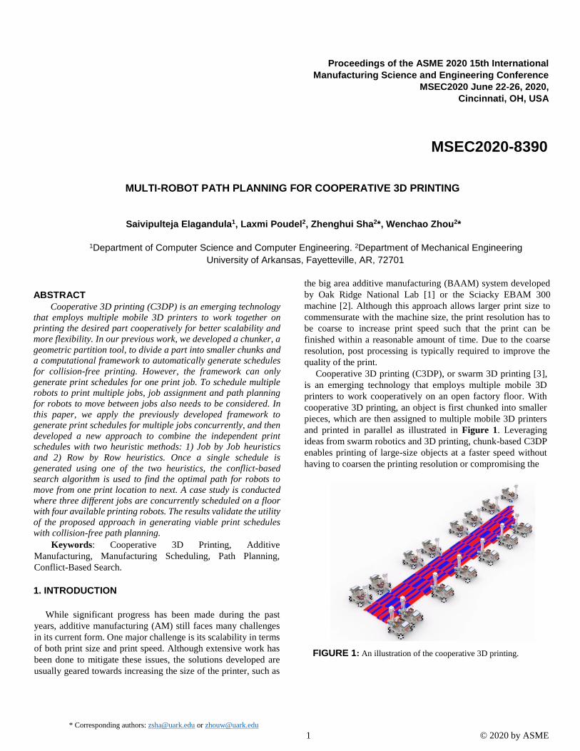
FIGURE 2: The computational framework presented in our previous
work where C3DP is divided into multiple discrete phases [5].
part strength [4]. This modular platform also significantly
reduces the cost as the mobile robots cost a fraction of what
industrial 3D printers cost.
One challenge of C3DP is to schedule multiple mobile 3D
printers to print the divided chunks in parallel with maximum
efficiency but no collision. In our previous studies, we have
developed a computational framework to generate a collision
free print schedule for given numbers of chunks and available
robots for one print job [5]. The flowchart of the developed
framework is presented in Figure 2. This framework takes
information about the chunks such as the total number of chunks,
the shape of individual chunks, the total number of available
robots, etc. and generates print schedules, which is described as
a directed dependency tree (DDT). The dependencies between
chunks indicate the order of print sequence and are generated
based on geometric constraints for a possible collision between
the active printing robots and the previously printed chunks.
However, this framework is lacking in two important aspects:
1. It can only be used to generate a print schedule for one
print job at a time (i.e., the print schedule is only for
printing one object). If multiple jobs are to be scheduled,
the print schedule must be generated independently for
every job. This results in situations where not all the
available resources are fully utilized during the
execution of the tasks
2. The framework does not take path planning into
considerations, i.e., as robot moves between chunks or
jobs, the path planning is ignored for simplification
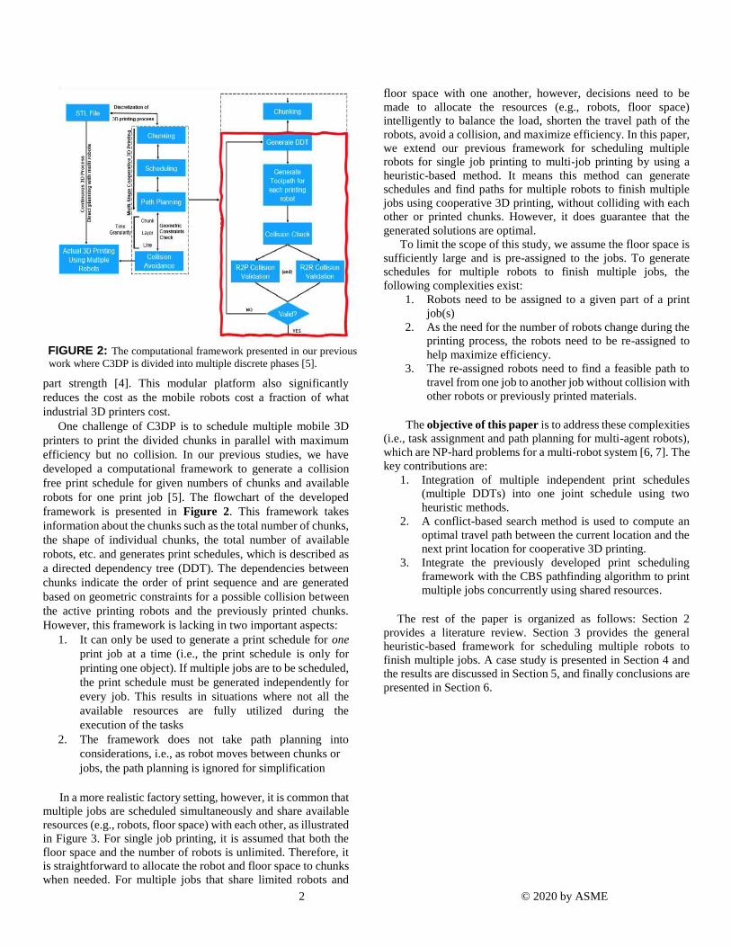
In a more realistic factory setting, however, it is common that
multiple jobs are scheduled simultaneously and share available
resources (e.g., robots, floor space) with each other, as illustrated
in Figure 3. For single job printing, it is assumed that both the
floor space and the number of robots is unlimited. Therefore, it
is straightforward to allocate the robot and floor space to chunks
when needed. For multiple jobs that share limited robots and
floor space with one another, however, decisions need to be
made to allocate the resources (e.g., robots, floor space)
intelligently to balance the load, shorten the travel path of the
robots, avoid a collision, and maximize efficiency. In this paper,
we extend our previous framework for scheduling multiple
robots for single job printing to multi-job printing by using a
heuristic-based method. It means this method can generate
schedules and find paths for multiple robots to finish multiple
jobs using cooperative 3D printing, without colliding with each
other or printed chunks. However, it does guarantee that the
generated solutions are optimal.
To limit the scope of this study, we assume the floor space is
sufficiently large and is pre-assigned to the jobs. To generate
schedules for multiple robots to finish multiple jobs, the
following complexities exist:
1. Robots need to be assigned to a given part of a print
job(s)
2. As the need for the number of robots change during the
printing process, the robots need to be re-assigned to
help maximize efficiency.
3. The re-assigned robots need to find a feasible path to
travel from one job to another job without collision with
other robots or previously printed materials.
The objective of this paper is to address these complexities
(i.e., task assignment and path planning for multi-agent robots),
which are NP-hard problems for a multi-robot system [6, 7]. The
key contributions are:
1. Integration of multiple independent print schedules
(multiple DDTs) into one joint schedule using two
heuristic methods.
2. A conflict-based search method is used to compute an
optimal travel path between the current location and the
next print location for cooperative 3D printing.
3. Integrate the previously developed print scheduling
framework with the CBS pathfinding algorithm to print
multiple jobs concurrently using shared resources.
The rest of the paper is organized as follows: Section 2
provides a literature review. Section 3 provides the general
heuristic-based framework for scheduling multiple robots to
finish multiple jobs. A case study is presented in Section 4 and
the results are discussed in Section 5, and finally conclusions are
presented in Section 6.
3 © 2020 by ASME
FIGURE 3: Typical scenario in a smart factory where multiple
jobs are scheduled simultaneously, and the resources (e.g., robots, floor space) are to be shared between multiple jobs.
2. LITERATURE REVIEW
Task assignment has been studied extensively in multi-robot
systems, which is typically devoted to objectives with discrete
tasks (e.g., assembly). Nunes et al. [8] provided a comprehensive
review of this topic. There has also been extensive research on
multi-agent pathfinding (MAPF). Pathfinding has many uses
including those in video games, robotics, and search and rescue
operations. Pathfinding has primarily been found in graph
traversal algorithms such as Dijkstra’s algorithm [9] or breadth-
first [10] or depth-first search [11]. These algorithms are useful in
finding optimal paths between two nodes of a graph. Similarly,
A* search [12] is a best-first search algorithm, i.e., it searches by
expanding towards the most promising node, which uses a
heuristic-based approach to find optimal solutions faster. Even
though A* has larger space complexity, it is widely used due to
its optimality and completeness. Moreover, A* also reaches its
solution faster than the previously stated graph traversals.
Conflict-Based Search (CBS) is another optimal pathfinding
algorithm for a multi-agent system that uses a two-level approach
where high-level search is done on a constraint tree (each node
include constraints on time and location for a single agent) and
low-level search is done on each node to find paths for all agents
that satisfies the constraints. There have been many expansions to
this search such as Enhanced Conflict Based Search or Conflict
Based Search with Target Assignment [13], [14], however, they
are all rooted in the same base algorithm. Li et al. used two
heuristics along with CBS for multi-agent path planning to
overcome the cardinal conflict only limitation of CBS [15].
Similarly, Solis et al. used extension of CBS discrete approach to
solving Sampling-based motion planning problems to produce
roadmaps that were optimal for multiple robots [16].
For C3DP, it is essential to combine the two NP-hard
problems (i.e., task allocation and multi-robot pathfinding) to find
a feasible solution. However, there is currently not any literature
where task assignment and MAPF principles or ideas are
successfully applied to C3DP. While both the task assignment and
path planning in the multi-agent system are widely studied
separately, a method for combining them to schedule multiple
robots for multiple jobs for C3DP does not exist.
3. GENERAL FRAMEWORK
Before introducing the general framework, it is important to
first define some concepts that will be used throughout the rest
of the paper.
● Floor is an entirety of the floor space in which robots can
move around and on which the objects are printed.
● Print job refers to a singular object that needs to be
printed.
● Print task refers to one or more chunks that are to be
printed.
● Robot is the mobile printing robot with a robotic arm that
3D prints objects can also be referred to as a Printer.
● Phase is a discretization of time that is used for
assignment decisions and planning. At the end of each
phase, tasks are assigned to individual printers and path
planning is done for each robot to move from the current
position to the location of the next print task. The number
of phases is equal to the total number of rows in a print
schedule.
● Task is a tuple that consists of a robot (R), a floor tile
(F), and a chunk (C) to be printed.
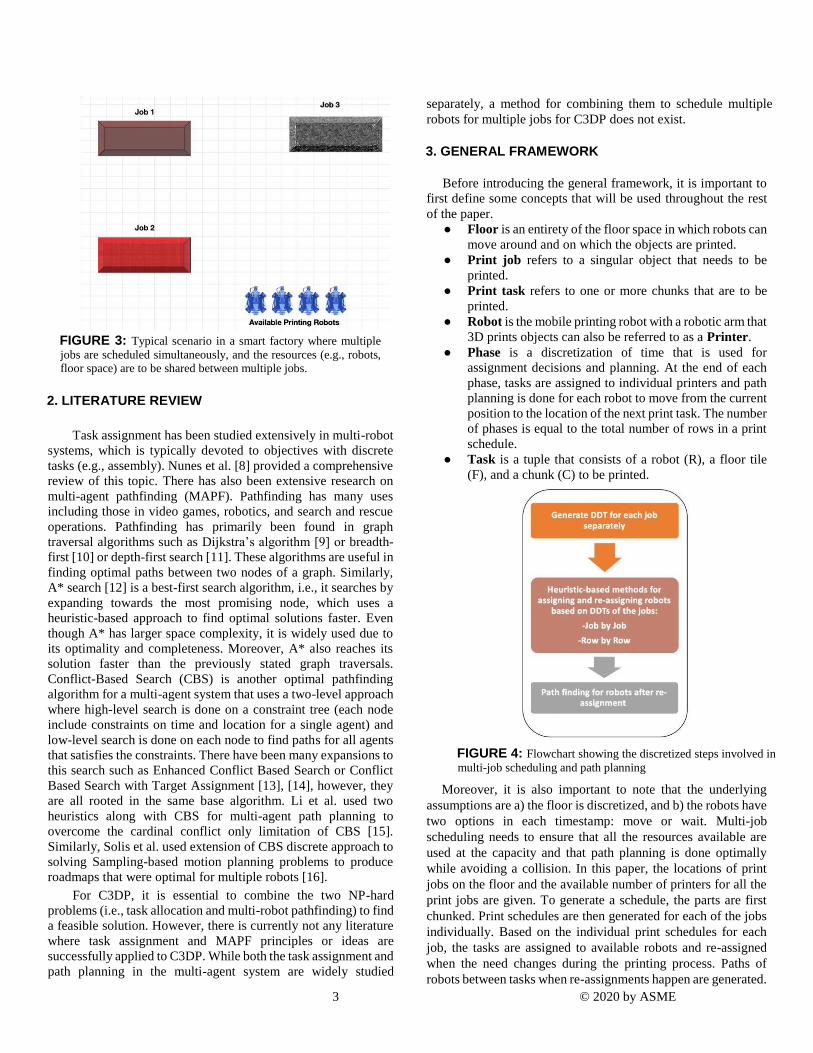
FIGURE 4: Flowchart showing the discretized steps involved in
multi-job scheduling and path planning
Moreover, it is also important to note that the underlying
assumptions are a) the floor is discretized, and b) the robots have
two options in each timestamp: move or wait. Multi-job
scheduling needs to ensure that all the resources available are
used at the capacity and that path planning is done optimally
while avoiding a collision. In this paper, the locations of print
jobs on the floor and the available number of printers for all the
print jobs are given. To generate a schedule, the parts are first
chunked. Print schedules are then generated for each of the jobs
individually. Based on the individual print schedules for each
job, the tasks are assigned to available robots and re-assigned
when the need changes during the printing process. Paths of
robots between tasks when re-assignments happen are generated.
4 © 2020 by ASME
This entire process can be divided into three steps, as shown in
Figure 4.
The details of each individual step of the general framework is
presented in subsequent sections. It is important to highlight that
the framework is used to generate an optimal toolpath between
the start location of the robot and the task location, but it uses
heuristic approach to assign robots to the tasks.
3.1 Generate DDT for each job separately
Before starting a print job, robots need to know the location
of the chunks as well as its own location. Therefore, each print
job needs to be allocated floor space so that we have spatial
information that will be used in the future to check for potential
collisions while computing the path planning. In addition to this,
having spatial information also allows us to develop constraints
to ensure that there is enough space between the active jobs for a
mobile robot to move from one location to another. Job placement
(placing each job at a specific location in the floor) is assumed to
be given before chunking
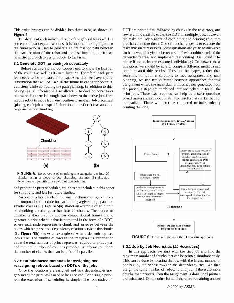
FIGURE 5: (a) outcome of chunking a rectangular bar into 20
chunks using a slope-surface chunking strategy (b) directed dependency tree with four rows and two columns.
and generating print schedules, which is not included in this paper
for simplicity and left for future studies.
An object is first chunked into smaller chunks using a chunker
– a computational module for partitioning a given large part into
smaller chunks [3]. Figure 5(a) shows an example of an output
of chunking a rectangular bar into 20 chunks. The output of
chunker is then used by another computational framework to
generate a print schedule that is outputted in the form of a DDT,
where each node represents a chunk and an edge between the
nodes which represents a dependency relation between the chunks
[5]. Figure 5(b) shows an example of what a dependency tree
looks like. The number of rows in the tree gives us information
about the total number of print sequences required to print a part
and the total number of columns provides us information about
the number of chunks that can be printed in parallel.
3.2 Heuristic-based methods for assigning and
reassigning robots based on DDTs of the jobs
Once the locations are assigned and task dependencies are
generated, the print tasks need to be executed. For a single print
job, the execution of scheduling is simple. The root nodes of
DDT are printed first followed by chunks in the next rows, one
row at a time until the end of the DDT. In multiple jobs, however,
the tasks are independent of each other and printing resources
are shared among them. One of the challenges is to execute the
tasks that share resources. Some questions are yet to be answered
such as: would it yield a better result if we combine each of the
dependency trees and implement the printing? Or would it be
better if the tasks are executed individually? To answer these
questions, we should be able to compare different methods and
obtain quantifiable results. Thus, in this paper, rather than
searching for optimal solutions to task assignment and path
planning, we use two different heuristic approaches for task
assignment where the individual print schedules generated from
the previous steps are combined into one schedule for all the
print jobs. These two methods can help us answer questions
posed earlier and provide quantifiable results that can be used for
comparison. These will later be compared to independently
printing the jobs.
FIGURE 6: Flowchart showing the JJ heuristic approach
3.2.1 Job by Job Heuristics (JJ Heuristics)
In this approach, we start with the first job and find the
maximum number of chunks that can be printed simultaneously.
This can be done by locating the row with the largest number of
nodes (i.e., the widest row) in the dependency tree. We then
assign the same number of robots to this job. If there are more
chunks than printers, then the assignment is done until printers
are exhausted. On the other hand, if there are remaining unused
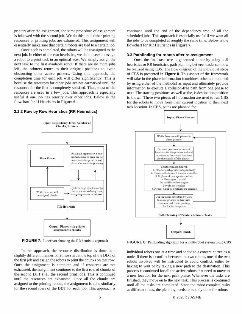
5 © 2020 by ASME
printers after the assignment, the same procedure of assignment
is followed with the second job. We do this until either printing
resources or printing jobs are exhausted. This assignment will
essentially make sure that certain robots are tied to a certain job.
Once a job is completed, the robots will be reassigned to the
next job. In either of the two heuristics, we do not seek to assign
a robot to a print task in an optimal way. We simply assign the
next task to the first available robot. If there are no more jobs
left, the printers return to their original positions to avoid
obstructing other active printers. Using this approach, the
completion time for each job will differ significantly. This is
because the resources for other jobs are not earmarked until the
resources for the first is completely satisfied. Thus, most of the
resources are used in a few jobs. This approach is especially
useful if one job has priority over other jobs. Below is the
flowchart for JJ Heuristics in Figure 6.
3.2.2 Row by Row Heuristics (RR Heuristics)
FIGURE 7: Flowchart showing the RR heuristic approach
In this approach, the resource distribution is done in a
slightly different manner. First, we start at the top of the DDT of
the first job and assign the robots to print the chunks on that row.
Once the assignment is complete and if resources are not
exhausted, the assignment continues to the first row of chunks of
the second DTT (i.e., the second print job). This is continued
until the resources are exhausted. Once all the chunks are
assigned to the printing robots, the assignment is done similarly
for the second rows of the DDT for each job. This approach is
continued until the end of the dependency tree of all the
scheduled jobs. This approach is especially useful if we want all
the jobs to be completed at roughly the same time. Below is the
flowchart for RR Heuristics in Figure 7.
3.3 Pathfinding for robots after re-assignment
Once the final task tree is generated either by using a JJ
heuristics or RR heuristics, path planning between tasks can now
be realized using CBS. The flow diagram of the individual steps
of CBS is presented in Figure 8. This aspect of the framework
will take in the phase information (combines schedule obtained
by using either of the methods) as input and ultimately provide
information to execute a collision-free path from one phase to
next. The starting positions, as well as the, is destination position
is known. These two pieces of information are used to run CBS
for the robots to move from their current location to their next
task location. In CBS, paths are planned for
FIGURE 8: Pathfinding algorithm for a multi-robot system using CBS
individual robots one at a time and added to a constraint tree as a
node. If there is a conflict between the two robots, one of the two
robots involved will be instructed to avoid conflict, either by
having to wait or by taking a new path to the destination. This
process is continued for all the active robots that need to move to
a new location for the next print phase. Whenever the tasks are
finished, they move on to the next task. This process is continued
until all the tasks are completed. Since the robot complete tasks
at different times, the planning needs to be only done for robots
6 © 2020 by ASME
that need to move to a new position and not for all the robots
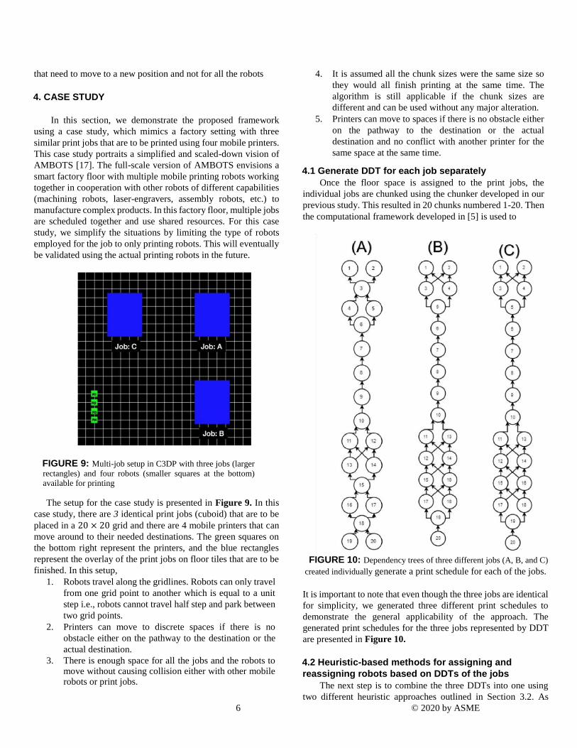
4. CASE STUDY
In this section, we demonstrate the proposed framework
using a case study, which mimics a factory setting with three
similar print jobs that are to be printed using four mobile printers.
This case study portraits a simplified and scaled-down vision of
AMBOTS [17]. The full-scale version of AMBOTS envisions a
smart factory floor with multiple mobile printing robots working
together in cooperation with other robots of different capabilities
(machining robots, laser-engravers, assembly robots, etc.) to
manufacture complex products. In this factory floor, multiple jobs
are scheduled together and use shared resources. For this case
study, we simplify the situations by limiting the type of robots
employed for the job to only printing robots. This will eventually
be validated using the actual printing robots in the future.
FIGURE 9: Multi-job setup in C3DP with three jobs (larger
rectangles) and four robots (smaller squares at the bottom) available for printing
The setup for the case study is presented in Figure 9. In this
case study, there are 3 identical print jobs (cuboid) that are to be
placed in a 20 × 20 grid and there are 4 mobile printers that can
move around to their needed destinations. The green squares on
the bottom right represent the printers, and the blue rectangles
represent the overlay of the print jobs on floor tiles that are to be
finished. In this setup,
1. Robots travel along the gridlines. Robots can only travel
from one grid point to another which is equal to a unit
step i.e., robots cannot travel half step and park between
two grid points.
2. Printers can move to discrete spaces if there is no
obstacle either on the pathway to the destination or the
actual destination.
3. There is enough space for all the jobs and the robots to move without causing collision either with other mobile robots or print jobs.
4. It is assumed all the chunk sizes were the same size so
they would all finish printing at the same time. The
algorithm is still applicable if the chunk sizes are
different and can be used without any major alteration.
5. Printers can move to spaces if there is no obstacle either
on the pathway to the destination or the actual
destination and no conflict with another printer for the
same space at the same time.
4.1 Generate DDT for each job separately
Once the floor space is assigned to the print jobs, the
individual jobs are chunked using the chunker developed in our
previous study. This resulted in 20 chunks numbered 1-20. Then
the computational framework developed in [5] is used to
FIGURE 10: Dependency trees of three different jobs (A, B, and C)
created individually generate a print schedule for each of the jobs.
It is important to note that even though the three jobs are identical
for simplicity, we generated three different print schedules to
demonstrate the general applicability of the approach. The
generated print schedules for the three jobs represented by DDT
are presented in Figure 10.
4.2 Heuristic-based methods for assigning and
reassigning robots based on DDTs of the jobs
The next step is to combine the three DDTs into one using
two different heuristic approaches outlined in Section 3.2. As
7 © 2020 by ASME
highlighted earlier, two different heuristic approaches were used
for combining the print schedules. The result of each of the
approaches is presented in Table 1. In the table, the second
column provides a combined schedule obtained using a job by job
heuristics whereas, the third column provides a combined print
schedule using row by row heuristics. JJ heuristic results in 20
phases whereas, RR results in 17 phases.
4.3 Pathfinding for robot after re-assignment
Finally, the path planning for the four robots working on three
similar jobs is done using the CBS method to avoid
Table 1: The combined print schedule generated using two different
heuristic method
collision and obtain an optimal path between the different
phases. Since path planning occurs in between phases, the inputs
for CBS are the current locations (starting locations if the next
phase is start phase or mount locations of the chunks that just
finished printing if next phase is not the last phase). The goal
locations are the mount locations or the locations at which the
robots have to be, to print the chunks next phase. This is done
iteratively until printing for all jobs is done. Once the inputs are
received, CBS plans for each robot independently and if there is
a conflict, it will constrain robots from being in a certain location
at a certain time until there is no conflict and robots can get to
where they need to be. Also, path planning is done before the
beginning of every phase for each heuristic approach so that
robots can get to where they need to be. Thus, for JJ heuristic,
the path planning is done 20 times, one for each phase whereas,
for RR heuristics the path planning was only done 17 times.
5. RESULTS AND DISCUSSION
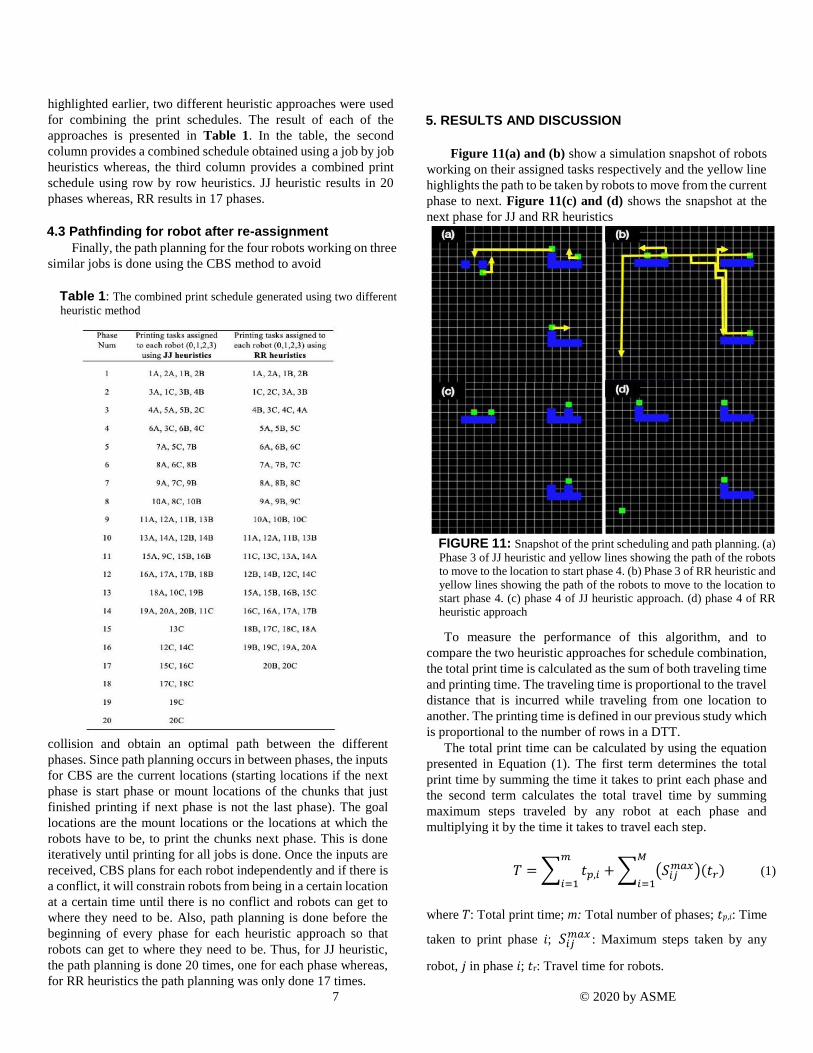
Figure 11(a) and (b) show a simulation snapshot of robots
working on their assigned tasks respectively and the yellow line
highlights the path to be taken by robots to move from the current
phase to next. Figure 11(c) and (d) shows the snapshot at the
next phase for JJ and RR heuristics
FIGURE 11: Snapshot of the print scheduling and path planning. (a)
Phase 3 of JJ heuristic and yellow lines showing the path of the robots to move to the location to start phase 4. (b) Phase 3 of RR heuristic and yellow lines showing the path of the robots to move to the location to start phase 4. (c) phase 4 of JJ heuristic approach. (d) phase 4 of RR heuristic approach
To measure the performance of this algorithm, and to
compare the two heuristic approaches for schedule combination,
the total print time is calculated as the sum of both traveling time
and printing time. The traveling time is proportional to the travel
distance that is incurred while traveling from one location to
another. The printing time is defined in our previous study which
is proportional to the number of rows in a DTT.
The total print time can be calculated by using the equation
presented in Equation (1). The first term determines the total
print time by summing the time it takes to print each phase and
the second term calculates the total travel time by summing
maximum steps traveled by any robot at each phase and
multiplying it by the time it takes to travel each step.
𝑇 = ∑ 𝑡𝑝,𝑖
𝑚
𝑖=1+ ∑ (𝑆𝑖𝑗
𝑚𝑎𝑥)(𝑡𝑟)𝑀
𝑖=1 (1)
where 𝑇: Total print time; m: Total number of phases; 𝑡𝑝,𝑖: Time
taken to print phase 𝑖; 𝑆𝑖𝑗𝑚𝑎𝑥 : Maximum steps taken by any
robot, 𝑗 in phase 𝑖; 𝑡r: Travel time for robots.
8 © 2020 by ASME
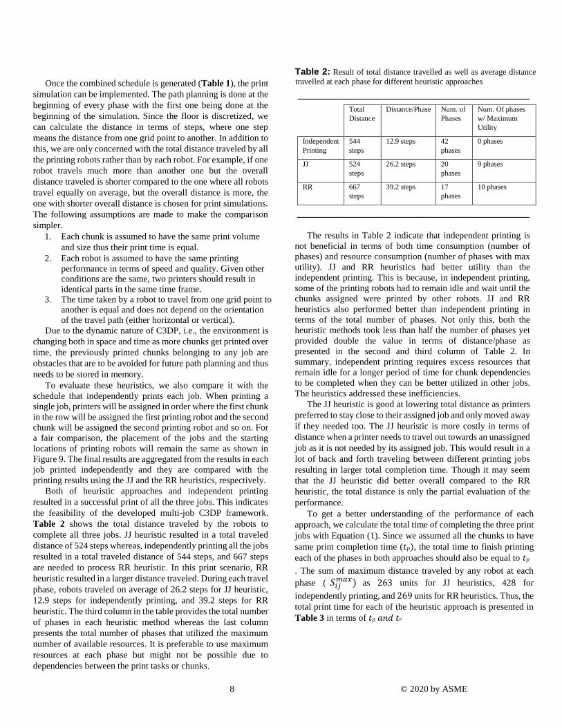
Once the combined schedule is generated (Table 1), the print
simulation can be implemented. The path planning is done at the
beginning of every phase with the first one being done at the
beginning of the simulation. Since the floor is discretized, we
can calculate the distance in terms of steps, where one step
means the distance from one grid point to another. In addition to
this, we are only concerned with the total distance traveled by all
the printing robots rather than by each robot. For example, if one
robot travels much more than another one but the overall
distance traveled is shorter compared to the one where all robots
travel equally on average, but the overall distance is more, the
one with shorter overall distance is chosen for print simulations.
The following assumptions are made to make the comparison
simpler.
1. Each chunk is assumed to have the same print volume
and size thus their print time is equal.
2. Each robot is assumed to have the same printing performance in terms of speed and quality. Given other conditions are the same, two printers should result in identical parts in the same time frame.
3. The time taken by a robot to travel from one grid point to another is equal and does not depend on the orientation of the travel path (either horizontal or vertical).
Due to the dynamic nature of C3DP, i.e., the environment is
changing both in space and time as more chunks get printed over
time, the previously printed chunks belonging to any job are
obstacles that are to be avoided for future path planning and thus
needs to be stored in memory.
To evaluate these heuristics, we also compare it with the
schedule that independently prints each job. When printing a
single job, printers will be assigned in order where the first chunk
in the row will be assigned the first printing robot and the second
chunk will be assigned the second printing robot and so on. For
a fair comparison, the placement of the jobs and the starting
locations of printing robots will remain the same as shown in
Figure 9. The final results are aggregated from the results in each
job printed independently and they are compared with the
printing results using the JJ and the RR heuristics, respectively.
Both of heuristic approaches and independent printing
resulted in a successful print of all the three jobs. This indicates
the feasibility of the developed multi-job C3DP framework.
Table 2 shows the total distance traveled by the robots to
complete all three jobs. JJ heuristic resulted in a total traveled
distance of 524 steps whereas, independently printing all the jobs
resulted in a total traveled distance of 544 steps, and 667 steps
are needed to process RR heuristic. In this print scenario, RR
heuristic resulted in a larger distance traveled. During each travel
phase, robots traveled on average of 26.2 steps for JJ heuristic,
12.9 steps for independently printing, and 39.2 steps for RR
heuristic. The third column in the table provides the total number
of phases in each heuristic method whereas the last column
presents the total number of phases that utilized the maximum
number of available resources. It is preferable to use maximum
resources at each phase but might not be possible due to
dependencies between the print tasks or chunks.
Table 2: Result of total distance travelled as well as average distance
travelled at each phase for different heuristic approaches
Total
Distance
Distance/Phase Num. of
Phases
Num. Of phases
w/ Maximum
Utility
Independent
Printing
544
steps
12.9 steps 42
phases
0 phases
JJ 524
steps
26.2 steps 20
phases
9 phases
RR 667
steps
39.2 steps 17
phases
10 phases
The results in Table 2 indicate that independent printing is
not beneficial in terms of both time consumption (number of
phases) and resource consumption (number of phases with max
utility). JJ and RR heuristics had better utility than the
independent printing. This is because, in independent printing,
some of the printing robots had to remain idle and wait until the
chunks assigned were printed by other robots. JJ and RR
heuristics also performed better than independent printing in
terms of the total number of phases. Not only this, both the
heuristic methods took less than half the number of phases yet
provided double the value in terms of distance/phase as
presented in the second and third column of Table 2. In
summary, independent printing requires excess resources that
remain idle for a longer period of time for chunk dependencies
to be completed when they can be better utilized in other jobs.
The heuristics addressed these inefficiencies.
The JJ heuristic is good at lowering total distance as printers
preferred to stay close to their assigned job and only moved away
if they needed too. The JJ heuristic is more costly in terms of
distance when a printer needs to travel out towards an unassigned
job as it is not needed by its assigned job. This would result in a
lot of back and forth traveling between different printing jobs
resulting in larger total completion time. Though it may seem
that the JJ heuristic did better overall compared to the RR
heuristic, the total distance is only the partial evaluation of the
performance.
To get a better understanding of the performance of each
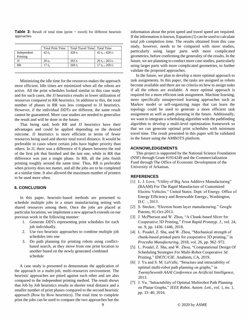
approach, we calculate the total time of completing the three print
jobs with Equation (1). Since we assumed all the chunks to have
same print completion time (𝑡𝑝), the total time to finish printing
each of the phases in both approaches should also be equal to 𝑡𝑝
. The sum of maximum distance traveled by any robot at each
phase ( 𝑆𝑖𝑗𝑚𝑎𝑥) as 263 units for JJ heuristics, 428 for
independently printing, and 269 units for RR heuristics. Thus, the
total print time for each of the heuristic approach is presented in
Table 3 in terms of 𝑡𝑝 𝑎𝑛𝑑 𝑡𝑟
9 © 2020 by ASME
Table 3: Result of total time (print + travel) for different heuristic
approaches
Total Print Time Total Travel Time Total Time
Independent
Printing
42 𝑡𝑝 428 𝑡𝑟 42 𝑡𝑝 + 428 𝑡𝑟
JJ 20 𝑡𝑝 263 𝑡𝑟 20 𝑡𝑝 + 263 𝑡𝑟
RR 17 𝑡𝑝 269 𝑡𝑟 17 𝑡𝑝 + 269 𝑡𝑟
Minimizing the idle time for the resources makes the approach
more efficient. Idle times are minimized when all the robots are
active. All the print schedules looked similar in this case study
and for such cases, the JJ heuristics results in lower utilization of
resources compared to RR heuristics. In addition to this, the total
number of phases in RR was less compared to JJ heuristics.
However, if the individual DDTs are different, the same result
cannot be guaranteed. More case studies are needed to generalize
the result and will be done in the future.
That being said, both RR and JJ heuristics have their
advantages and could be applied depending on the desired
outcome. JJ heuristics is more efficient in terms of fewer
resources being used and shorter total travel distance. It would be
preferable in cases where certain jobs have higher priority than
others. In JJ, there was a difference of 6 phases between the end
of the first job that finished and the last one, while in RR that
difference was just a single phase. In RR, all the jobs finish
printing roughly around the same time. Thus, RR is preferable
when priority does not matter, and all the jobs are to be completed
at a similar time. It also allowed the maximum number of printers
to be used more often.
6. CONCLUSION
In this paper, heuristic-based methods are presented to
schedule multiple jobs in a smart manufacturing setting with
shared resources among them. Once the jobs are placed at
particular locations, we implement a new approach extends on our
previous work in the following manner:
1. Generate DDTs representing print schedules for each
job individually.
2. Use two heuristic approaches to combine multiple job
schedules into one
3. Do path planning for printing robots using conflict-
based search, as they move from one print location to
another based on the newly generated combined
schedule
A case study is presented to demonstrate the application of
the approach in a multi-job, multi-resources environment. The
heuristic approaches are pitted against each other and are also
compared to the independent printing method. The result shows
that Job by Job heuristics results in shorter total distance and a
smaller number of print phases compared to the second heuristic
approach (Row by Row heuristics). The total time to complete
print the jobs can be used to compare the two approaches but the
information about the print speed and travel speed are required.
If the information is known, Equation (1) can be used to calculate
total job completion time. The results obtained from this case
study, however, needs to be compared with more studies,
particularly using larger parts with more complicated
geometries, before confirming the generality of the results. In the
future, we are planning to conduct more case studies, particularly
using larger parts with more complicated geometries, to further
validate the proposed approaches. In the future, we plan to develop a more optimal approach to
task assignments. In this paper, the tasks are assigned as robots
become available and there are no criteria on how to assign tasks
if all the robots are available. A more optimal approach is
required for a more efficient task assignment. Machine learning,
more specifically unsupervised learning approaches such as
Markov model or self-organizing maps that can learn the
topology could be used to generate a more efficient task
assignment as well as path planning in the future. Additionally,
we want to integrate a scheduling algorithm with the pathfinding
algorithm to develop a multi-level optimization framework so
that we can generate optimal print schedules with minimum
travel time. The result presented in this paper will be validated
in the future using the AMBOTS platform.
ACKNOWLEDGEMENTS
This project is supported by the National Science Foundation (NSF) through Grant #1914249 and the Commercialization Fund through The Office of Economic Development of the University of Arkansas.
REFERENCES
[1] L. J. Love, “Utility of Big Area Additive Manufacturing”
(BAAM) For The Rapid Manufacture of Customized
Electric Vehicles.” United States. Dept. of Energy. Office of
Energy Efficiency and Renewable Energy;, Washington,
D.C. :, 2015.
[2] S. Stecker, “Electron beam layer manufacturing.” Google
Patents, 01-Oct-2013.
[3] J. McPherson and W. Zhou, “A Chunk-based Slicer for
Cooperative 3D Printing,” From Rapid Prototyp. J., vol. 24,
no. 9, pp. 1436–1446, 2018.
[4] L. Poudel, Z. Sha, and W. Zhou, “Mechanical strength of
chunk-based printed parts for cooperative 3D printing,” in
Procedia Manufacturing, 2018, vol. 26, pp. 962–972.
[5] L. Poudel, Z. Sha, and W. Zhou, “Computational Design Of
Scheduling Strategies For Multi-Robot Cooperative 3d
Printing,” IDETC/CIE. Anahiem, CA, 2019.
[6] J. Yu and S. M. LaValle, “Structure and intractability of
optimal multi-robot path planning on graphs,” in
TwentySeventh AAAI Conference on Artificial Intelligence,
2013.
[7] J. Yu, “Intractability of Optimal Multirobot Path Planning
on Planar Graphs,” IEEE Robot. Autom. Lett., vol. 1, no. 1,
pp. 33–40, 2016.
10 © 2020 by ASME
[8] E. Nunes, M. Manner, H. Mitiche, and M. Gini, “A
taxonomy for task allocation problems with temporal and
ordering constraints,” Rob. Auton. Syst., vol. 90, pp. 55–70,
2017.
[9] J.-C. Chen, “Dijkstra’s shortest path algorithm,” J. Formaliz.
Math., vol. 15, no. 9, pp. 237–247, 2003.
[10] B. Awerbuch and R. Gallager, “A new distributed algorithm
to find breadth first search trees,” IEEE Trans. Inf. Theory,
vol. 33, no. 3, pp. 315–322, 1987.
[11] B. Awerbuch, “A new distributed depth-first-search
algorithm,” Inf. Process. Lett., vol. 20, no. 3, pp. 147–150,
1985.
[12] J. Yao, C. Lin, X. Xie, A. J. Wang, and C.-C. Hung, “Path
planning for virtual human motion using improved A* star
algorithm,” in 2010 Seventh international conference on
information technology: new generations, 2010, pp. 1154–
1158.
[13] G. Sharon, R. Stern, A. Felner, and N. R. Sturtevant,
“Conflict-based search for optimal multi-agent pathfinding,”
Artif. Intell., vol. 219, pp. 40–66, 2015.
[14] M. Barer, G. Sharon, R. Stern, and A. Felner, “Suboptimal
variants of the conflict-based search algorithm for the
multiagent pathfinding problem,” in Seventh Annual
Symposium on Combinatorial Search, 2014.
[15] J. Li, A. Felner, E. Boyarski, H. Ma, and S. Koenig,
“Improved heuristics for multi-agent path finding with
conflict-based search,” in Proceedings of the 28th
International Joint Conference on Artificial Intelligence,
2019, pp. 442–449.
[16] I. Solis, R. Sandström, J. Motes, and N. Amato,
RoadmapOptimal Multi-robot Motion Planning using
Conflict-Based Search. 2019.
[17] I. Solis, R. Sandström, J. Motes, and N. Amato,
RoadmapOptimal Multi-robot Motion Planning using
Conflict-Based Search. 2019.