Embed Size (px)
Citation preview
MultiCam FlashRam H971-r4b, J930-r2, K520, LC520
M2521/M2621/M3521, HP4/HP5/SB5, M2545/M3545,
M2524/M3524 Control Boards
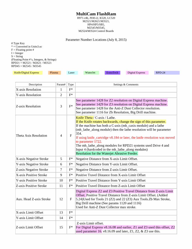
Parameter Number Locations (July 8, 2015)
# Type Key * = Converted in Units3.uc F = Floating point # I = Integer S = String (Floating Point #’s, Integers, & Strings) RPD21 = M2521 / M2621 / M3521 RPD45 = M2545 / M3545
Knife/Digital Express Plasma Laser WaterJet ExtraTech Digital Express RPD-24
Description Param# Type Settings & Comments
X-axis Resolution 1 F* Y-axis Resolution 2 F*
Z-axis Resolution 3 F*
See parameter 1428 for Z2 resolution on Digital Express machine. See parameter 1429 for Z3 resolution on Digital Express machine. See parameter 1428 for the Anti-Z Dust Collector resolution. See parameter 1116 for Zb Resolution, Big Drill machine.
Theta Axis Resolution 4 F
Knife Theta / C-axis / Lathe. If the Knife rotates backwards, change the sign of this parameter. If the machine has both a C-axis (mh_caxis module) and a lathe (mh_lathe_along module) then the lathe resolution will be parameter 354. If using knife_cartridge v8.184 or later, the knife resolution was moved to parameter 1722. The mh_lathe_along modules for RPD21 systems used Drive 4 and Input 4 (hardcoded in the mh_lathe_along modules) Resolution for the Waterjet Abrasive Feeder.
X-axis Negative Stroke 5 F* Negative Distance from X-axis Limit Offset. Y-axis Negative Stroke 6 F* Negative Distance from Y-axis Limit Offset. Z-axis Negative Stroke 7 F* Negative Distance from Z-axis Limit Offset. X-axis Positive Stroke 9 F* Positive Travel Distance from X-axis Limit Offset Y-axis Positive Stroke 10 F* Positive Travel Distance from Y-axis Limit Offset Z-axis Positive Stroke 11 F* Positive Travel Distance from Z-axis Limit Offset
Aux. Head Z-axis Stroke 12 F
Digital Express Z2 and Z3 Positive Travel Distance from Z-axis Limit Offset. Positive Travel Distance from Z-axis Limit Offset. (Added 5.24)Used for Tools 21 (Z2) and 22 (Z3) Aux Tools.Zb Max Stroke, Big Drill machine (See params 1120 and 1116) Used for Anti-Z Dust Collector max stroke.
X-axis Limit Offset 13 F* Y-axis Limit Offset 14 F*
Z-axis Limit Offset 15 F* Z-axis Limit offset. For Digital Express v8.16.08 and earlier, Z1 and Z3 used this offset, Z2 used parameter 16. v8.16.09 and later, Z1, Z2, & Z3 use this.
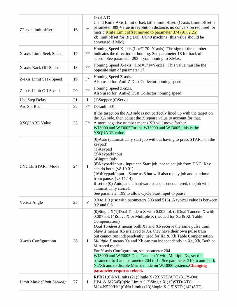
Z2 axis limit offset 16 F
Dual ATC C and Knife Axis Limit offset, lathe limit offset. (C-axis Limit offset is parameter 389)Value in revolution distance, no conversion required for metric.Knife Limit offset moved to parameter 374 (r8.02.25) Zb limit offset for Big Drill UC40 machine (this value should be converted if MM)
X-axis Limit Seek Speed 17 F* Homing Speed X-axis.(Loc#170=Y-axis). The sign of the number indicates the direction of homing. See parameter 18 for back off speed. See parameter 293 if you homing to XMax.
X-axis Back Off Speed 18 F* Homing Speed X-axis. (Loc#171=Y-axis). This value must be the opposite sign of parameter 17.
Z-axis Limit Seek Speed 19 F* Homing Speed Z-axis. Also used for Anti-Z Dust Collector homing speed.
Z-axis Limit Off Speed 20 F* Homing Speed Z-axis. Also used for Anti-Z Dust Collector homing speed.
Use Step Delay 21 I (1)Stepper (0)Servo Arc Set Res 22 F* Default .001
XSQUARE Value 23 F*
If the target on the XB side is not perfectly lined up with the target on the XA side, then adjust the X square value to account for that. A more negative number means XB will move farther. WJ3000 and WJ3005For the WJ3000 and WJ3005, this is the YSQUARE value.
CYCLE START Mode 24 I
(0)Auto (automatically start job without having to press START on the keypad) (1)Keypad (2)Keypad/Input (4)Input Only (8)Keypad/Input - Input can Start job, not select job from DNC, Key can do both. (v8.10.01) (16)Keypad/Input – Same as 8 but will also replay job and continue from pause. (v8.11.14) If set to (0) Auto, and a hardware pause is encountered, the job will automatically cancel. See parameter 199 to allow Cycle Start input to pause.
Vertex Angle 25 F 0.0 to 1.0 (use with parameters 503 and 513). A typical value is between 0.2 and 0.6.
X-axis Configuration 26 I
(0)Single X(1)Dual Tandem X with 0.002 tol. (2)Dual Tandem X with 0.007 tol. (4)Slave X or Multiple X (needed for Xa & Xb Table Compensation) Dual Tandem X means both Xa and Xb receive the same pulse train. Slave X means Xb is slaved to Xa, they have their own pulse train but cannot run independently, used for Xa & Xb Table Compensation. Multiple X means Xa and Xb can run independently in Xa, Xb, Both or Mirrored mode. For Y-axis Configuration, see parameter 204. WJ3000 and WJ3005 Dual Tandem Y with Multiple Xs, set this parameter to 4 and parameter 204 to 1. See parameter 210 to auto park Xa/Xb and to disable Mirror mode on WJ3000 systems.Changing parameter requires reboot.
Limit Mask (Limit Seeked) 27 I RPD21(0)No Limits (21)Single X (23)STD/ATC (31)Y-Ovr HP4 & M2545(0)No Limits (13)Single X (15)STD/ATC M24-K520/H/J (0)No Limits (13)Single X (15)STD (143)ATC
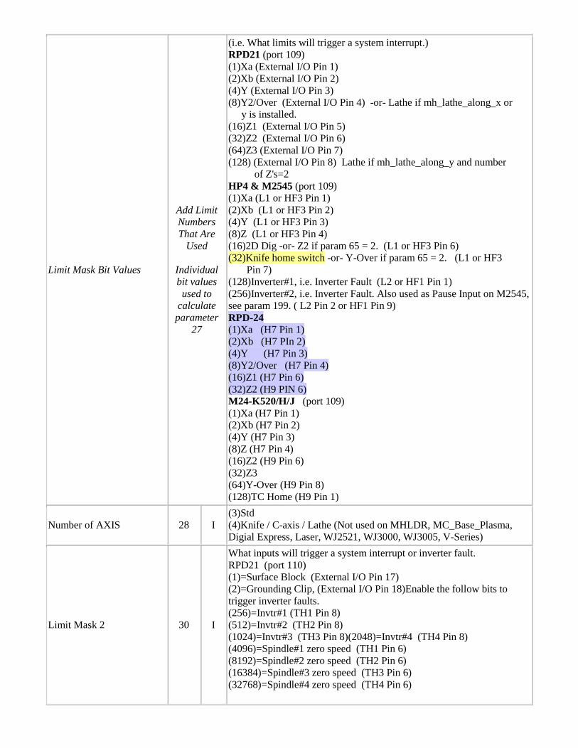
Limit Mask Bit Values
Add Limit Numbers That Are
Used
Individual bit values
used to calculate parameter
27
(i.e. What limits will trigger a system interrupt.) RPD21 (port 109) (1)Xa (External I/O Pin 1) (2)Xb (External I/O Pin 2) (4)Y (External I/O Pin 3) (8)Y2/Over (External I/O Pin 4) -or- Lathe if mh_lathe_along_x or y is installed. (16)Z1 (External I/O Pin 5) (32)Z2 (External I/O Pin 6) (64)Z3 (External I/O Pin 7) (128) (External I/O Pin 8) Lathe if mh_lathe_along_y and number of Z's=2 HP4 & M2545 (port 109) (1)Xa (L1 or HF3 Pin 1) (2)Xb (L1 or HF3 Pin 2) (4)Y (L1 or HF3 Pin 3) (8)Z (L1 or HF3 Pin 4) (16)2D Dig -or- Z2 if param 65 = 2. (L1 or HF3 Pin 6) (32)Knife home switch -or- Y-Over if param 65 = 2. (L1 or HF3 Pin 7) (128)Inverter#1, i.e. Inverter Fault (L2 or HF1 Pin 1) (256)Inverter#2, i.e. Inverter Fault. Also used as Pause Input on M2545, see param 199. ( L2 Pin 2 or HF1 Pin 9) RPD-24 (1)Xa (H7 Pin 1) (2)Xb (H7 PIn 2) (4)Y (H7 Pin 3) (8)Y2/Over (H7 Pin 4) (16)Z1 (H7 Pin 6) (32)Z2 (H9 PIN 6) M24-K520/H/J (port 109) (1)Xa (H7 Pin 1) (2)Xb (H7 Pin 2) (4)Y (H7 Pin 3) (8)Z (H7 Pin 4) (16)Z2 (H9 Pin 6) (32)Z3 (64)Y-Over (H9 Pin 8) (128)TC Home (H9 Pin 1)
Number of AXIS 28 I (3)Std (4)Knife / C-axis / Lathe (Not used on MHLDR, MC_Base_Plasma, Digial Express, Laser, WJ2521, WJ3000, WJ3005, V-Series)
Limit Mask 2 30 I
What inputs will trigger a system interrupt or inverter fault. RPD21 (port 110) (1)=Surface Block (External I/O Pin 17) (2)=Grounding Clip, (External I/O Pin 18)Enable the follow bits to trigger inverter faults. (256)=Invtr#1 (TH1 Pin 8) (512)=Invtr#2 (TH2 Pin 8) (1024)=Invtr#3 (TH3 Pin 8)(2048)=Invtr#4 (TH4 Pin 8) (4096)=Spindle#1 zero speed (TH1 Pin 6) (8192)=Spindle#2 zero speed (TH2 Pin 6) (16384)=Spindle#3 zero speed (TH3 Pin 6) (32768)=Spindle#4 zero speed (TH4 Pin 6)
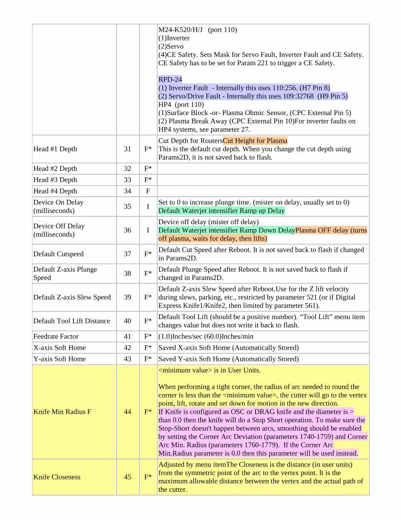
M24-K520/H/J (port 110) (1)Inverter (2)Servo (4)CE Safety. Sets Mask for Servo Fault, Inverter Fault and CE Safety. CE Safety has to be set for Param 221 to trigger a CE Safety. RPD-24 (1) Inverter Fault - Internally this uses 110:256. (H7 Pin 8) (2) Servo/Drive Fault - Internally this uses 109:32768 (H9 Pin 5) HP4 (port 110) (1)Surface Block -or- Plasma Ohmic Sensor, (CPC External Pin 5) (2) Plasma Break Away (CPC External Pin 10)For inverter faults on HP4 systems, see parameter 27.
Head #1 Depth 31 F* Cut Depth for RoutersCut Height for Plasma This is the default cut depth. When you change the cut depth using Params2D, it is not saved back to flash.
Head #2 Depth 32 F* Head #3 Depth 33 F* Head #4 Depth 34 F Device On Delay (milliseconds) 35 I Set to 0 to increase plunge time. (mister on delay, usually set to 0)
Default Waterjet intensifier Ramp up Delay
Device Off Delay (milliseconds) 36 I
Device off delay (mister off delay) Default Waterjet intensifier Ramp Down DelayPlasma OFF delay (turns off plasma, waits for delay, then lifts)
Default Cutspeed 37 F* Default Cut Speed after Reboot. It is not saved back to flash if changed in Params2D.
Default Z-axis Plunge Speed 38 F* Default Plunge Speed after Reboot. It is not saved back to flash if
changed in Params2D.
Default Z-axis Slew Speed 39 F* Default Z-axis Slew Speed after Reboot.Use for the Z lift velocity during slews, parking, etc., restricted by parameter 521 (or if Digital Express Knife1/Knife2, then limited by parameter 561).
Default Tool Lift Distance 40 F* Default Tool Lift (should be a positive number). “Tool Lift” menu item changes value but does not write it back to flash.
Feedrate Factor 41 F* (1.0)Inches/sec (60.0)Inches/min X-axis Soft Home 42 F* Saved X-axis Soft Home (Automatically Stored) Y-axis Soft Home 43 F* Saved Y-axis Soft Home (Automatically Stored)
Knife Min Radius F 44 F*
<minimum value> is in User Units. When performing a tight corner, the radius of arc needed to round the corner is less than the <minimum value>, the cutter will go to the vertex point, lift, rotate and set down for motion in the new direction. If Knife is configured as OSC or DRAG knife and the diameter is > than 0.0 then the knife will do a Stop Short operation. To make sure the Stop-Short doesn't happen between arcs, smoothing should be enabled by setting the Corner Arc Deviation (parameters 1740-1759) and Corner Arc Min. Radius (parameters 1760-1779). If the Corner Arc Min.Radius parameter is 0.0 then this parameter will be used instead.
Knife Closeness 45 F*
Adjusted by menu itemThe Closeness is the distance (in user units) from the symmetric point of the arc to the vertex point. It is the maximum allowable distance between the vertex and the actual path of the cutter.
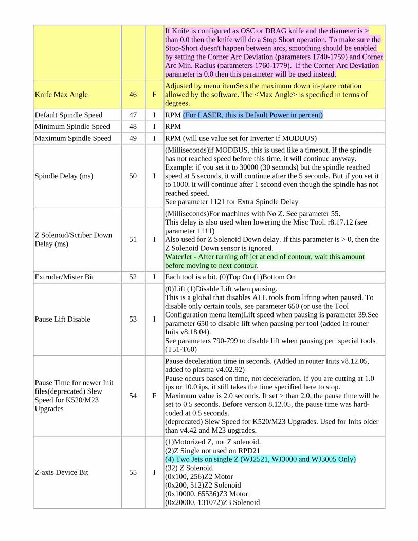
If Knife is configured as OSC or DRAG knife and the diameter is > than 0.0 then the knife will do a Stop Short operation. To make sure the Stop-Short doesn't happen between arcs, smoothing should be enabled by setting the Corner Arc Deviation (parameters 1740-1759) and Corner Arc Min. Radius (parameters 1760-1779). If the Corner Arc Deviation parameter is 0.0 then this parameter will be used instead.
Knife Max Angle 46 F Adjusted by menu itemSets the maximum down in-place rotation allowed by the software. The <Max Angle> is specified in terms of degrees.
Default Spindle Speed 47 I RPM (For LASER, this is Default Power in percent) Minimum Spindle Speed 48 I RPM Maximum Spindle Speed 49 I RPM (will use value set for Inverter if MODBUS)
Spindle Delay (ms) 50 I
(Milliseconds)if MODBUS, this is used like a timeout. If the spindle has not reached speed before this time, it will continue anyway. Example: if you set it to 30000 (30 seconds) but the spindle reached speed at 5 seconds, it will continue after the 5 seconds. But if you set it to 1000, it will continue after 1 second even though the spindle has not reached speed. See parameter 1121 for Extra Spindle Delay
Z Solenoid/Scriber Down Delay (ms) 51 I
(Milliseconds)For machines with No Z. See parameter 55. This delay is also used when lowering the Misc Tool. r8.17.12 (see parameter 1111) Also used for Z Solenoid Down delay. If this parameter is > 0, then the Z Solenoid Down sensor is ignored. WaterJet - After turning off jet at end of contour, wait this amount before moving to next contour.
Extruder/Mister Bit 52 I Each tool is a bit. (0)Top On (1)Bottom On
Pause Lift Disable 53 I
(0)Lift (1)Disable Lift when pausing. This is a global that disables ALL tools from lifting when paused. To disable only certain tools, see parameter 650 (or use the Tool Configuration menu item)Lift speed when pausing is parameter 39.See parameter 650 to disable lift when pausing per tool (added in router Inits v8.18.04). See parameters 790-799 to disable lift when pausing per special tools (T51-T60)
Pause Time for newer Init files(deprecated) Slew Speed for K520/M23 Upgrades
54 F
Pause deceleration time in seconds. (Added in router Inits v8.12.05, added to plasma v4.02.92) Pause occurs based on time, not deceleration. If you are cutting at 1.0 ips or 10.0 ips, it still takes the time specified here to stop. Maximum value is 2.0 seconds. If set > than 2.0, the pause time will be set to 0.5 seconds. Before version 8.12.05, the pause time was hard-coded at 0.5 seconds. (deprecated) Slew Speed for K520/M23 Upgrades. Used for Inits older than v4.42 and M23 upgrades.
Z-axis Device Bit 55 I
(1)Motorized Z, not Z solenoid. (2)Z Single not used on RPD21 (4) Two Jets on single Z (WJ2521, WJ3000 and WJ3005 Only) (32) Z Solenoid (0x100, 256)Z2 Motor (0x200, 512)Z2 Solenoid (0x10000, 65536)Z3 Motor (0x20000, 131072)Z3 Solenoid
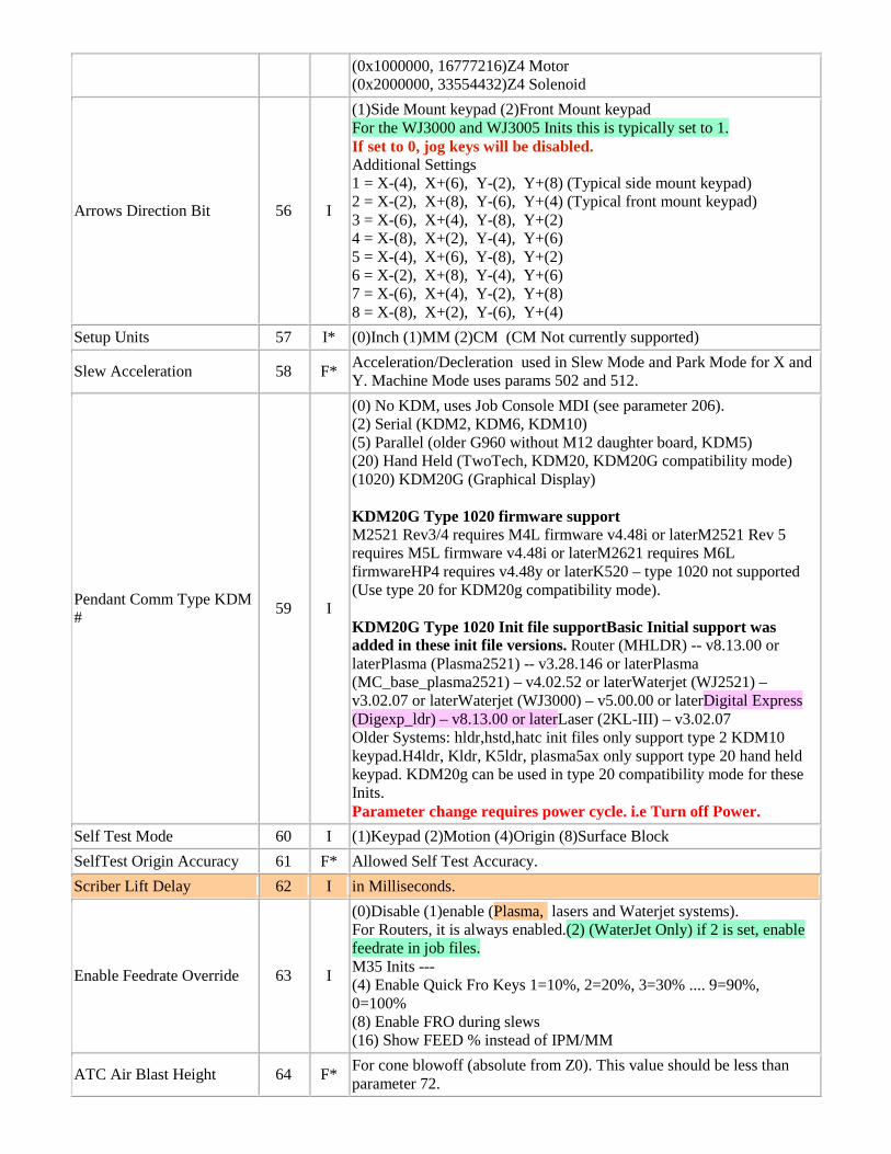
(0x1000000, 16777216)Z4 Motor (0x2000000, 33554432)Z4 Solenoid
Arrows Direction Bit 56 I
(1)Side Mount keypad (2)Front Mount keypad For the WJ3000 and WJ3005 Inits this is typically set to 1. If set to 0, jog keys will be disabled. Additional Settings 1 = X-(4), X+(6), Y-(2), Y+(8) (Typical side mount keypad) 2 = X-(2), X+(8), Y-(6), Y+(4) (Typical front mount keypad) 3 = X-(6), X+(4), Y-(8), Y+(2) 4 = X-(8), X+(2), Y-(4), Y+(6) 5 = X-(4), X+(6), Y-(8), Y+(2) 6 = X-(2), X+(8), Y-(4), Y+(6) 7 = X-(6), X+(4), Y-(2), Y+(8) 8 = X-(8), X+(2), Y-(6), Y+(4)
Setup Units 57 I* (0)Inch (1)MM (2)CM (CM Not currently supported)
Slew Acceleration 58 F* Acceleration/Decleration used in Slew Mode and Park Mode for X and Y. Machine Mode uses params 502 and 512.
Pendant Comm Type KDM # 59 I
(0) No KDM, uses Job Console MDI (see parameter 206). (2) Serial (KDM2, KDM6, KDM10) (5) Parallel (older G960 without M12 daughter board, KDM5) (20) Hand Held (TwoTech, KDM20, KDM20G compatibility mode) (1020) KDM20G (Graphical Display) KDM20G Type 1020 firmware support M2521 Rev3/4 requires M4L firmware v4.48i or laterM2521 Rev 5 requires M5L firmware v4.48i or laterM2621 requires M6L firmwareHP4 requires v4.48y or laterK520 – type 1020 not supported (Use type 20 for KDM20g compatibility mode). KDM20G Type 1020 Init file supportBasic Initial support was added in these init file versions. Router (MHLDR) -- v8.13.00 or laterPlasma (Plasma2521) -- v3.28.146 or laterPlasma (MC_base_plasma2521) – v4.02.52 or laterWaterjet (WJ2521) – v3.02.07 or laterWaterjet (WJ3000) – v5.00.00 or laterDigital Express (Digexp_ldr) – v8.13.00 or laterLaser (2KL-III) – v3.02.07 Older Systems: hldr,hstd,hatc init files only support type 2 KDM10 keypad.H4ldr, Kldr, K5ldr, plasma5ax only support type 20 hand held keypad. KDM20g can be used in type 20 compatibility mode for these Inits. Parameter change requires power cycle. i.e Turn off Power.
Self Test Mode 60 I (1)Keypad (2)Motion (4)Origin (8)Surface Block SelfTest Origin Accuracy 61 F* Allowed Self Test Accuracy. Scriber Lift Delay 62 I in Milliseconds.
Enable Feedrate Override 63 I
(0)Disable (1)enable (Plasma, lasers and Waterjet systems). For Routers, it is always enabled.(2) (WaterJet Only) if 2 is set, enable feedrate in job files. M35 Inits --- (4) Enable Quick Fro Keys 1=10%, 2=20%, 3=30% .... 9=90%, 0=100% (8) Enable FRO during slews (16) Show FEED % instead of IPM/MM
ATC Air Blast Height 64 F* For cone blowoff (absolute from Z0). This value should be less than parameter 72.
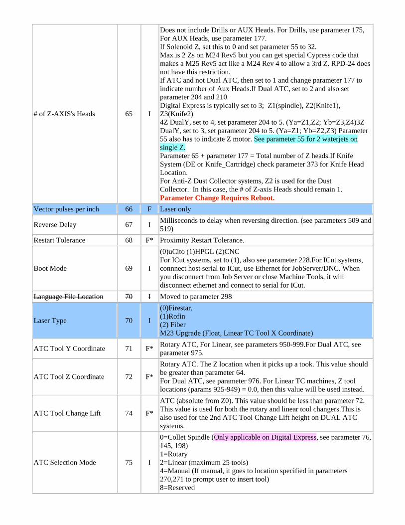
# of Z-AXIS's Heads 65 I
Does not include Drills or AUX Heads. For Drills, use parameter 175, For AUX Heads, use parameter 177. If Solenoid Z, set this to 0 and set parameter 55 to 32. Max is 2 Zs on M24 Rev5 but you can get special Cypress code that makes a M25 Rev5 act like a M24 Rev 4 to allow a 3rd Z. RPD-24 does not have this restriction. If ATC and not Dual ATC, then set to 1 and change parameter 177 to indicate number of Aux Heads.If Dual ATC, set to 2 and also set parameter 204 and 210. Digital Express is typically set to 3; Z1(spindle), Z2(Knife1), Z3(Knife2) 4Z DualY, set to 4, set parameter 204 to 5. (Ya=Z1,Z2; Yb=Z3,Z4)3Z DualY, set to 3, set parameter 204 to 5. (Ya=Z1; Yb=Z2,Z3) Parameter 55 also has to indicate Z motor. See parameter 55 for 2 waterjets on single Z. Parameter 65 + parameter 177 = Total number of Z heads.If Knife System (DE or Knife_Cartridge) check parameter 373 for Knife Head Location. For Anti-Z Dust Collector systems, Z2 is used for the Dust Collector. In this case, the # of Z-axis Heads should remain 1. Parameter Change Requires Reboot.
Vector pulses per inch 66 F Laser only
Reverse Delay 67 I Milliseconds to delay when reversing direction. (see parameters 509 and 519)
Restart Tolerance 68 F* Proximity Restart Tolerance.
Boot Mode 69 I
(0)uCito (1)HPGL (2)CNC For ICut systems, set to (1), also see parameter 228.For ICut systems, connnect host serial to ICut, use Ethernet for JobServer/DNC. When you disconnect from Job Server or close Machine Tools, it will disconnect ethernet and connect to serial for ICut.
Language File Location 70 I Moved to parameter 298
Laser Type 70 I
(0)Firestar, (1)Rofin (2) Fiber M23 Upgrade (Float, Linear TC Tool X Coordinate)
ATC Tool Y Coordinate 71 F* Rotary ATC, For Linear, see parameters 950-999.For Dual ATC, see parameter 975.
ATC Tool Z Coordinate 72 F*
Rotary ATC. The Z location when it picks up a took. This value should be greater than parameter 64. For Dual ATC, see parameter 976. For Linear TC machines, Z tool locations (params 925-949) = 0.0, then this value will be used instead.
ATC Tool Change Lift 74 F*
ATC (absolute from Z0). This value should be less than parameter 72. This value is used for both the rotary and linear tool changers.This is also used for the 2nd ATC Tool Change Lift height on DUAL ATC systems.
ATC Selection Mode 75 I
0=Collet Spindle (Only applicable on Digital Express, see parameter 76, 145, 198) 1=Rotary 2=Linear (maximum 25 tools) 4=Manual (If manual, it goes to location specified in parameters 270,271 to prompt user to insert tool) 8=Reserved
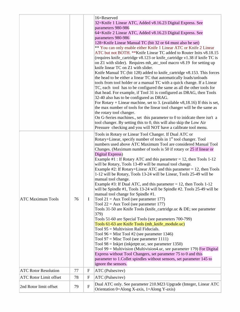
16=Reserved 32=Knife 1 Linear ATC, Added v8.16.23 Digital Express. See parameters 980-986 64=Knife 2 Linear ATC, Added v8.16.23 Digital Express. See parameters 980-986 128=Knife Linear Manual TC (bit 32 or 64 must also be set) ** You can only enable either Knife 1 Linear ATC or Knife 2 Linear ATC but not BOTH. **Knife Linear TC added to Router Inits v8.18.15 (requires knife_cartridge v8.123 or knife_cartridge v1.38 if knife TC is on Z1 with slider). Requires mh_atc_tool macro v8.19 for setting up knife linear TC on Z1 with slider. Knife Manual TC (bit 128) added to knife_cartridge v8.153. This forces the head to be either a linear TC that automatically loads/unloads tools from tool holder or a manual TC with a quick change. If a Linear TC, each tool has to be configured the same as all the other tools for that head. For example, if Tool 31 is configured as DRAG, then Tools 32-40 also has to be configured as DRAG. For Rotary + Linear machine, set to 3. (available v8,18.16) If this is set, the max number of tools for the linear tool changer will be the same as the rotary tool changer. On G-Series machines., set this parameter to 0 to inidcate there isn't a tool changer. By setting this to 0, this will also skip the Low Air Pressure checking and you will NOT have a calibrate tool menu.
ATC Maximum Tools 76 I
Tools in Rotary or Linear Tool Changer. If Dual ATC or Rotary+Linear, specify number of tools in 1st tool changer. Tool numbers used above ATC Maximum Tool are considered Manual Tool Changes. (Maximum number of tools is 50 if rotary or 25 if linear or Digital Express) Example #1 : If Rotary ATC and this parameter = 12, then Tools 1-12 will be Rotary, Tools 13-49 will be manual tool change. Example #2: If Rotary+Linear ATC and this parameter = 12, then Tools 1-12 will be Rotary, Tools 13-24 will be Linear, Tools 25-49 will be manual tool change. Example #3: If Dual ATC, and this parameter = 12, then Tools 1-12 will be Spindle #1, Tools 13-24 will be Spindle #2. Tools 25-49 will be manual tool change for Spindle #1. Tool 21 = Aux Tool (see parameter 177) Tool 22 = Aux Tool (see parameter 177) Tools 31-50 are Knife Tools (knife_cartridge.uc & DE; see parameter 379) Tools 51-60 are Special Tools (see parameters 700-799) Tools 61-63 are Knife Tools (mh_knife_module.uc) Tool 95 = Multivision Rail Fiducials. Tool 96 = Mist Tool #2 (see parameter 1346) Tool 97 = Misc Tool (see parameter 1111) Tool 98 = Inkjet (inkjetptr.uc, see parameter 1350) Tool 99 = Multivision (Multivision4.uc, see parameter 179) For Digital Express without Tool Changers, set parameter 75 to 0 and this parameter to 1.Collet spindles without sensors, set parameter 145 to ignore the sensors.
ATC Rotor Resolution 77 F ATC (Pulses/rev) ATC Rotor Limit offset 78 F ATC (Pulses/rev)
2nd Rotor limit offset 79 F Dual ATC only. See parameter 210.M23 Upgrade (Integer, Linear ATC Orientation 0=Along X-axis, 1=Along Y-axis)
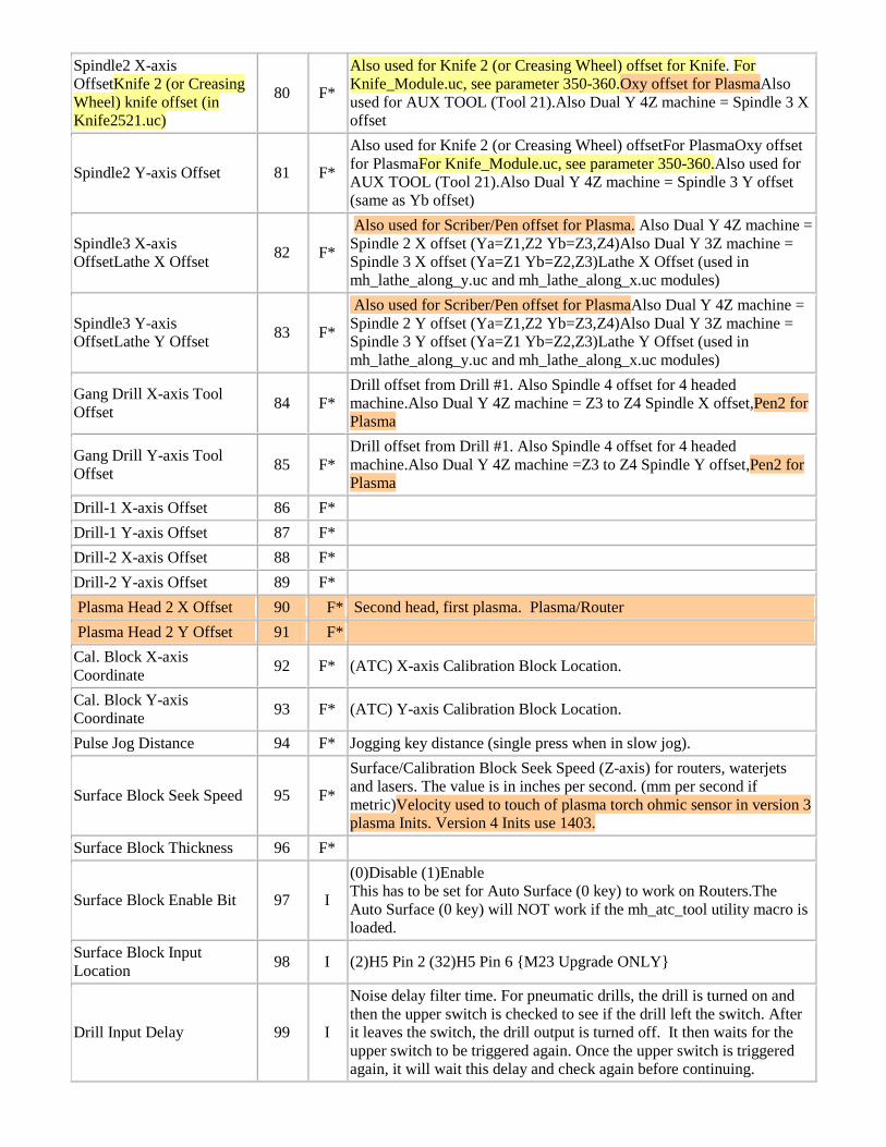
Spindle2 X-axis OffsetKnife 2 (or Creasing Wheel) knife offset (in Knife2521.uc)
80 F*
Also used for Knife 2 (or Creasing Wheel) offset for Knife. For Knife_Module.uc, see parameter 350-360.Oxy offset for PlasmaAlso used for AUX TOOL (Tool 21).Also Dual Y 4Z machine = Spindle 3 X offset
Spindle2 Y-axis Offset 81 F*
Also used for Knife 2 (or Creasing Wheel) offsetFor PlasmaOxy offset for PlasmaFor Knife_Module.uc, see parameter 350-360.Also used for AUX TOOL (Tool 21).Also Dual Y 4Z machine = Spindle 3 Y offset (same as Yb offset)
Spindle3 X-axis OffsetLathe X Offset 82 F*
Also used for Scriber/Pen offset for Plasma. Also Dual Y 4Z machine = Spindle 2 X offset (Ya=Z1,Z2 Yb=Z3,Z4)Also Dual Y 3Z machine = Spindle 3 X offset (Ya=Z1 Yb=Z2,Z3)Lathe X Offset (used in mh_lathe_along_y.uc and mh_lathe_along_x.uc modules)
Spindle3 Y-axis OffsetLathe Y Offset 83 F*
Also used for Scriber/Pen offset for PlasmaAlso Dual Y 4Z machine = Spindle 2 Y offset (Ya=Z1,Z2 Yb=Z3,Z4)Also Dual Y 3Z machine = Spindle 3 Y offset (Ya=Z1 Yb=Z2,Z3)Lathe Y Offset (used in mh_lathe_along_y.uc and mh_lathe_along_x.uc modules)
Gang Drill X-axis Tool Offset 84 F*
Drill offset from Drill #1. Also Spindle 4 offset for 4 headed machine.Also Dual Y 4Z machine = Z3 to Z4 Spindle X offset,Pen2 for Plasma
Gang Drill Y-axis Tool Offset 85 F*
Drill offset from Drill #1. Also Spindle 4 offset for 4 headed machine.Also Dual Y 4Z machine =Z3 to Z4 Spindle Y offset,Pen2 for Plasma
Drill-1 X-axis Offset 86 F* Drill-1 Y-axis Offset 87 F* Drill-2 X-axis Offset 88 F* Drill-2 Y-axis Offset 89 F* Plasma Head 2 X Offset 90 F* Second head, first plasma. Plasma/Router Plasma Head 2 Y Offset 91 F* Cal. Block X-axis Coordinate 92 F* (ATC) X-axis Calibration Block Location.
Cal. Block Y-axis Coordinate 93 F* (ATC) Y-axis Calibration Block Location.
Pulse Jog Distance 94 F* Jogging key distance (single press when in slow jog).
Surface Block Seek Speed 95 F*
Surface/Calibration Block Seek Speed (Z-axis) for routers, waterjets and lasers. The value is in inches per second. (mm per second if metric)Velocity used to touch of plasma torch ohmic sensor in version 3 plasma Inits. Version 4 Inits use 1403.
Surface Block Thickness 96 F*
Surface Block Enable Bit 97 I
(0)Disable (1)Enable This has to be set for Auto Surface (0 key) to work on Routers.The Auto Surface (0 key) will NOT work if the mh_atc_tool utility macro is loaded.
Surface Block Input Location 98 I (2)H5 Pin 2 (32)H5 Pin 6 {M23 Upgrade ONLY}
Drill Input Delay 99 I
Noise delay filter time. For pneumatic drills, the drill is turned on and then the upper switch is checked to see if the drill left the switch. After it leaves the switch, the drill output is turned off. It then waits for the upper switch to be triggered again. Once the upper switch is triggered again, it will wait this delay and check again before continuing.
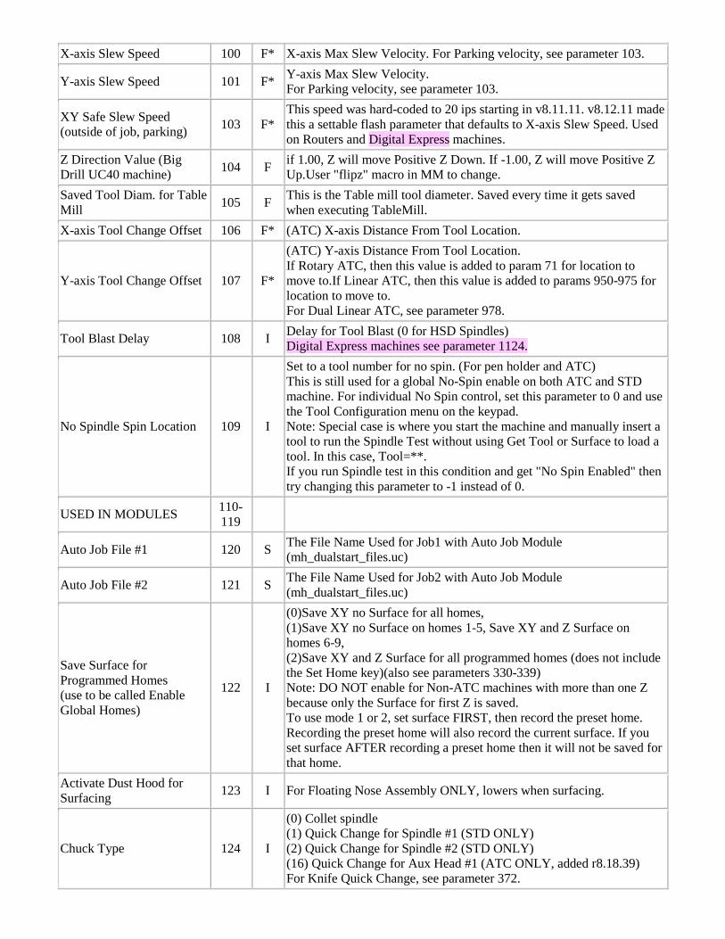
X-axis Slew Speed 100 F* X-axis Max Slew Velocity. For Parking velocity, see parameter 103.
Y-axis Slew Speed 101 F* Y-axis Max Slew Velocity. For Parking velocity, see parameter 103.
XY Safe Slew Speed (outside of job, parking) 103 F*
This speed was hard-coded to 20 ips starting in v8.11.11. v8.12.11 made this a settable flash parameter that defaults to X-axis Slew Speed. Used on Routers and Digital Express machines.
Z Direction Value (Big Drill UC40 machine) 104 F if 1.00, Z will move Positive Z Down. If -1.00, Z will move Positive Z
Up.User "flipz" macro in MM to change. Saved Tool Diam. for Table Mill 105 F This is the Table mill tool diameter. Saved every time it gets saved
when executing TableMill. X-axis Tool Change Offset 106 F* (ATC) X-axis Distance From Tool Location.
Y-axis Tool Change Offset 107 F*
(ATC) Y-axis Distance From Tool Location. If Rotary ATC, then this value is added to param 71 for location to move to.If Linear ATC, then this value is added to params 950-975 for location to move to. For Dual Linear ATC, see parameter 978.
Tool Blast Delay 108 I Delay for Tool Blast (0 for HSD Spindles) Digital Express machines see parameter 1124.
No Spindle Spin Location 109 I
Set to a tool number for no spin. (For pen holder and ATC) This is still used for a global No-Spin enable on both ATC and STD machine. For individual No Spin control, set this parameter to 0 and use the Tool Configuration menu on the keypad. Note: Special case is where you start the machine and manually insert a tool to run the Spindle Test without using Get Tool or Surface to load a tool. In this case, Tool=**. If you run Spindle test in this condition and get "No Spin Enabled" then try changing this parameter to -1 instead of 0.
USED IN MODULES 110-119
Auto Job File #1 120 S The File Name Used for Job1 with Auto Job Module (mh_dualstart_files.uc)
Auto Job File #2 121 S The File Name Used for Job2 with Auto Job Module (mh_dualstart_files.uc)
Save Surface for Programmed Homes (use to be called Enable Global Homes)
122 I
(0)Save XY no Surface for all homes, (1)Save XY no Surface on homes 1-5, Save XY and Z Surface on homes 6-9, (2)Save XY and Z Surface for all programmed homes (does not include the Set Home key)(also see parameters 330-339) Note: DO NOT enable for Non-ATC machines with more than one Z because only the Surface for first Z is saved. To use mode 1 or 2, set surface FIRST, then record the preset home. Recording the preset home will also record the current surface. If you set surface AFTER recording a preset home then it will not be saved for that home.
Activate Dust Hood for Surfacing 123 I For Floating Nose Assembly ONLY, lowers when surfacing.
Chuck Type 124 I
(0) Collet spindle (1) Quick Change for Spindle #1 (STD ONLY) (2) Quick Change for Spindle #2 (STD ONLY) (16) Quick Change for Aux Head #1 (ATC ONLY, added r8.18.39) For Knife Quick Change, see parameter 372.
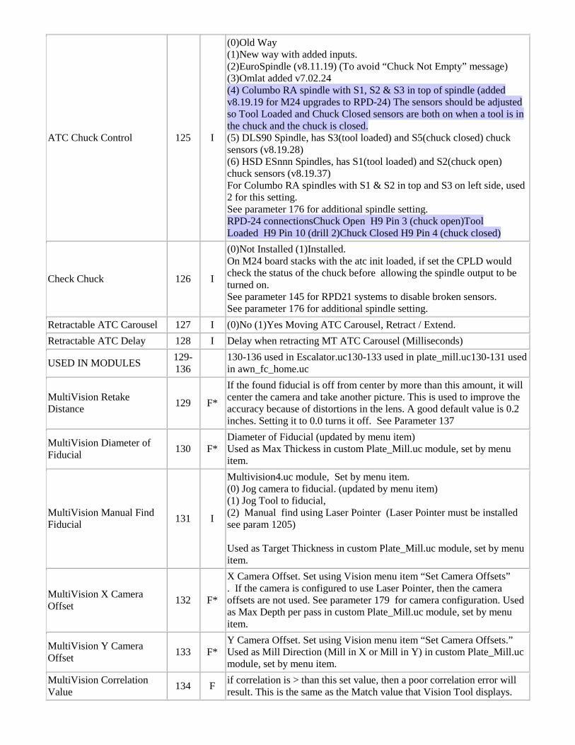
ATC Chuck Control 125 I
(0)Old Way (1)New way with added inputs. (2)EuroSpindle (v8.11.19) (To avoid “Chuck Not Empty” message) (3)Omlat added v7.02.24 (4) Columbo RA spindle with S1, S2 & S3 in top of spindle (added v8.19.19 for M24 upgrades to RPD-24) The sensors should be adjusted so Tool Loaded and Chuck Closed sensors are both on when a tool is in the chuck and the chuck is closed. (5) DLS90 Spindle, has S3(tool loaded) and S5(chuck closed) chuck sensors (v8.19.28) (6) HSD ESnnn Spindles, has S1(tool loaded) and S2(chuck open) chuck sensors (v8.19.37) For Columbo RA spindles with S1 & S2 in top and S3 on left side, used 2 for this setting. See parameter 176 for additional spindle setting. RPD-24 connectionsChuck Open H9 Pin 3 (chuck open)Tool Loaded H9 Pin 10 (drill 2)Chuck Closed H9 Pin 4 (chuck closed)
Check Chuck 126 I
(0)Not Installed (1)Installed. On M24 board stacks with the atc init loaded, if set the CPLD would check the status of the chuck before allowing the spindle output to be turned on. See parameter 145 for RPD21 systems to disable broken sensors. See parameter 176 for additional spindle setting.
Retractable ATC Carousel 127 I (0)No (1)Yes Moving ATC Carousel, Retract / Extend. Retractable ATC Delay 128 I Delay when retracting MT ATC Carousel (Milliseconds)
USED IN MODULES 129-136 130-136 used in Escalator.uc130-133 used in plate_mill.uc130-131 used
in awn_fc_home.uc
MultiVision Retake Distance 129 F*
If the found fiducial is off from center by more than this amount, it will center the camera and take another picture. This is used to improve the accuracy because of distortions in the lens. A good default value is 0.2 inches. Setting it to 0.0 turns it off. See Parameter 137
MultiVision Diameter of Fiducial 130 F*
Diameter of Fiducial (updated by menu item) Used as Max Thickess in custom Plate_Mill.uc module, set by menu item.
MultiVision Manual Find Fiducial 131 I
Multivision4.uc module, Set by menu item. (0) Jog camera to fiducial. (updated by menu item) (1) Jog Tool to fiducial, (2) Manual find using Laser Pointer (Laser Pointer must be installed see param 1205) Used as Target Thickness in custom Plate_Mill.uc module, set by menu item.
MultiVision X Camera Offset 132 F*
X Camera Offset. Set using Vision menu item “Set Camera Offsets” . If the camera is configured to use Laser Pointer, then the camera offsets are not used. See parameter 179 for camera configuration. Used as Max Depth per pass in custom Plate_Mill.uc module, set by menu item.
MultiVision Y Camera Offset 133 F*
Y Camera Offset. Set using Vision menu item “Set Camera Offsets.” Used as Mill Direction (Mill in X or Mill in Y) in custom Plate_Mill.uc module, set by menu item.
MultiVision Correlation Value 134 F if correlation is > than this set value, then a poor correlation error will
result. This is the same as the Match value that Vision Tool displays.
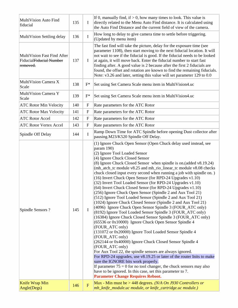
MultiVision Auto Find fiducial 135 I
If 0, manually find, if > 0, how many times to look. This value is directly related to the Menu Auto Find distance. It is calculated using the Auto Find Distance and the current field of view of the camera.
MultiVision Settling delay 136 I How long to delay to give camera time to settle before triggering. (Updated by menu item)
MultiVision Fast Find After FiducialFiducial Number removed.
137 I
The fast find will take the picture, delay for the exposure time (see parameter 1108), then start moving to the next fiducial location. It will not wait to see if the fiducial is good. If the fiducial needs to be looked at again, it will move back. Enter the fiducial number to start fast finding after. A good value is 2 because after the first 2 fiducials are found, the offset and rotation are known to find the remaining fiducials. Note: v3.26 and later, setting this value will set parameter 129 to 0.0
MultiVision Camera X Scale 138 F* Set using Set Camera Scale menu item in MultiVision4.uc
MultiVision Camera Y Scale 139 F* Set using Set Camera Scale menu item in MultiVision4.uc
ATC Rotor Min Velocity 140 F Rate parameters for the ATC Rotor ATC Rotor Max Velocity 141 F Rate parameters for the ATC Rotor ATC Rotor Accel 142 F Rate parameters for the ATC Rotor ATC Rotor Vertex Accel 143 F Rate parameters for the ATC Rotor
Spindle Off Delay 144 I Ramp Down Time for ATC Spindle before opening Dust collector after pausing.M23/K520 Spindle Off Delay.
Spindle Sensors ? 145 I
(1) Ignore Chuck Open Sensor (Open Chuck delay used instead, see param 190) (2) Ignore Tool Loaded Sensor (4) Ignore Chuck Closed Sensor (8) Ignore Chuck Closed Sensor when spindle is on.(added v8.19.24) (mh_atcb_tc module v8.25 and mh_rio_linear_tc module v8.08 checks chuck closed input every second when running a job with spindle on. ) (16) Invert Chuck Open Sensor (for RPD-24 Upgrades v1.10) (32) Invert Tool Loaded Sensor (for RPD-24 Upgrades v1.10) (64) Invert Chuck Closed Senor (for RPD-24 Upgrades v1.10) (256) Ignore Chuck Open Sensor (Spindle 2 and Aux Tool 21) (512) Ignore Tool Loaded Sensor (Spindle 2 and Aux Tool 21) (1024) Ignore Chuck Closed Sensor (Spindle 2 and Aux Tool 21) (4096) Ignore Chuck Open Sensor Spindle 3 (FOUR_ATC only) (8192) Ignore Tool Loaded Sensor Spindle 3 (FOUR_ATC only) (16384) Ignore Chuck Closed Sensor Spindle 3 (FOUR_ATC only) (65536 or 0x10000) Ignore Chuck Open Sensor Spindle 4 (FOUR_ATC only) (131072 or 0x20000) Ignore Tool Loaded Sensor Spindle 4 (FOUR_ATC only) (262144 or 0x40000) Ignore Chuck Closed Sensor Spindle 4 (FOUR_ATC only) For Aux Tool 22, the spindle sensors are always ignored. For RPD-24 upgrades, use v8.19.25 or later of the router Inits to make sure the IGNORE bits work properly. If parameter 75 = 0 for no tool changer, the chuck sensors may also have to be ignored. In this case, set this parameter to 7. Parameter Change Requires Reboot.
Knife Wrap Min Angle(Degs) 146 F Max - Min must be > 448 degrees. (N/A On J930 Controllers or
mh_knife_module.uc module, or knife_cartridge.uc module.)
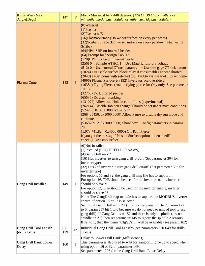
Knife Wrap Max Angle(Degs) 147 F Max - Min must be > 448 degrees. (N/A On J930 Controllers or
mh_knife_module.uc module, or knife_cartridge.uc module.)
Plasma Cutter 148 I
(0)Waterjet (1)Plasma (2)Plasma w/Z. (16)PlasmaSurface (Do we set surface on every pendown) (32)Scribe Surface (Do we set surface on every pendown when using Scribe) (64)HP4, SBE on Internal header (64) Prompt for "Assign Tool 1" (128)HP4, Scribe on Internal header (256) 0 = Sample ATHC, 1 = Use Material Library voltage (512) 0 = Use normal ZTrack params, 1 = Use thin gage ZTrack params (1024) 1=Disable surface block relay if consumables appear shorted. (2048) 1=Set home with selected tool, 0=Always use tool 1 to set home (4096) Plasma Surface 2(8192) Invert surface override 2 (16384) Flying Pierce (enable flying pierce for Oxy only. See parameter 1093) (32768) Do Buffered pierces (65536) Do argon marking. (131072) Allow true Hole in cut utilities (experimental) (262144) Disable Job pen change. Should be set under most conditions. (524288, 0x0008 0000) UseRad? (268435456, 0x1000 0000) Allow Pause to disable dry run mode and continue (536870912, 0x2000 0000) Show bevel Config parameters in params 2d. (1,073,741,824, 0x4000 0000) Off Path Pierce. If you get the message "Plasma Surface option not enabled!", check (16)PlasmaSurface
Gang Drill Installed 149 I
(0)Not Installed (1)Installed (REQUIRED FOR SAWS) (4)Gang Drill on Z2 (16) Has inverter to turn gang drill on/off (Set parameter 304 for inverter type) (32) Has 2nd inverter to turn gang drill on/off (Set parameter 306 for inverter type) For options 16 and 32, the gang drill map file has to support it. For option 16, TH3 should be used for the inverter enable, inverter should be slave #5 For option 32, TH4 should be used for the inverter enable, inverter should be slave #7 Note: The GangDrill map module has to support the MODBUS inverter control if option 16 or 32 is selected. Set to 5 if Gang Drill is on Z2 (If on Z2, set param 65 to 2, param 177 to 0, param 257 bit 1 to 0 because we do not need to unload tool to use gang drill). If Gang Drill is on Z2 and there is only 1 spindle (i.e. no spindle on Z2) then set parameter 145 to ignore the spindle 2 sensors. If set to 1, then the menu “CfgGDrill” will be available (see param 162)
Gang Drill Tool Length (drills 1-10)
150-159 F* Individual Gang Drill Tool Lengths (see parameters 620-649 for drills
11-40)
Gang Drill Bank Lower Delay 160 I
Delay to Lower Drill Bank (Milliseconds) This parameter is also used to wait for gang drill to be up to speed when using option 16 or 32 of parameter 149. See parameter 1296 for the Gang Drill Bank Raise Delay.
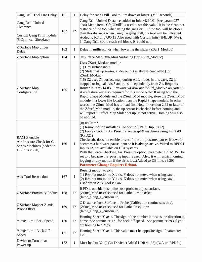
Gang Drill Tool Fire Delay 161 I Delay for each Drill Tool to Fire down or lower. (Milliseconds)
Gang Drill Unload Clearance Custom Gang Drill module (GDrill_cal_2head.uc)
162 F*
Gang Drill Unload Distance, added to Inits v8.10.01 (see param 257 also) Menu item “CfgGDrill” is used to set this value. It is the clearance distance of the tool when using the gang drill. If the tool will be closer than this distance when using the gang drill, the tool will be unloaded. Added to K5ldr v7.05.13 Also used with Custom Inits (H4LDR_PW). 1=Gang Drill could reach cal block, 0=could not.
Z Surface Map Slider Delay 163 I Delay in milliseconds when lowering the slider (ZSurf_Mod.uc)
Z Surface Map option 164 I 0=Surface Map, 3=Radius Surfacing (for ZSurf_Mod.uc)
Z Surface Map Configuration 165 I
Uses ZSurf_Mod.uc module (1) Has surface input (2) Slider has up sensor, slider output is always controlled.(for ZSurf_Mod.uc) (16) Z2 uses Z1 surface map during ALL mode. In this case, Z2 is mapped to logical axis 5 and runs independently from Z1. Requires Router Inits v8.14.03, Firmware v4.48w and ZSurf_Mod v2.48.Note: 5 Axis feature key also required for this mode.Note: If using both the Rapid Shape Module and the ZSurf_Mod module, store the ZSurf_Mod module in a lower file location than the Rapid Shape module. In other words, the ZSurf_Mod has to load first.Note: In version 2.62 or later of the ZSurf_Mod module, the up sensor is checked before homing and will report "Surface Map Slider not up" if not active. Homing will also be aborted.
RAM-Z enable Air Pressure Check for G-Series Machines (added to DE Inits v8.20)
166 I
(0) no RamZ (1) RamZ option installed (Connect to RPD21 Input #12) (2) Force checking Air Pressure on GraphX machines using Input #9 (RPD21) Checks air, does not enable drives if low air pressure, pauses if low. It becomes a hardware pause input so it is always active. Wired to RPD21 Input#12, not available on HP4 systems. With the Force Checking Air Pressure option, parameter 199 MUST be set to 0 because the pausing input is used. Also, it will restrict homing, jogging or any motion if the air is low.(Added to DE Inits v8.20) Parameter Change Requires Reboot.
Aux Tool Restriction 167 I
Restrict motion to axis (1) Restrict motion to X-axis, Y does not move when using saw. (2) Restrict motion to Y-axis, X does not move when using saw. Used when Aux Tool is Saw.
Z Surface Proximity Radius 168 F* If PD is outside this radius, use probe to adjust surface. (ZSurf_Mod.uc)Also used for Lathe Limit Offset (lathe_along_x_custom.uc)
Z Surface Mapper Z-axis Probe Offset 169 F*
Z Distance from Surface to Probe (Calibration routine sets this). (ZSurf_Mod.uc)Also used for Lathe Resolution (lathe_along_x_custom.uc)
Y-axis Limit Seek Speed 170 F* Homing Speed Y-axis. The sign of the number indicates the direction to home. See parameter 171 for back off speed. See parameter 293 if you are homing to YMax.
Y-axis Limit Back Off Speed 171 F* Homing Speed Y-axis. This value must be opposite sign of parameter
170. Device to Turn on at Power-up 172 I Must be 0 to 32. (0)No Device. (Added LDR v1.68) (N/A on RPD21)
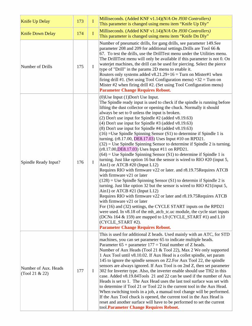
Knife Up Delay 173 I Milliseconds. (Added KNF v1.14)(N/A On J930 Controllers) This parameter is changed using menu item “Knife Up Dly”
Knife Down Delay 174 I Milliseconds. (Added KNF v1.14)(N/A On J930 Controllers) This parameter is changed using menu item “Knife Dn Dly”
Number of Drills 175 I
Number of pneumatic drills, for gang drills, see parameter 149.See parameter 208 and 209 for additional settings.Drills are Tool 66 & 67. To test the drills, use the DrillTest menu under the Utilities menu. The DrilllTest menu will only be available if this parameter is not 0. On waterjet machines, the drill can be used for piercing. Select the pierce type of "Drill" in the params 2D menu to enable it. Routers only systems added v8.21.29+16 = Turn on Mister#1 when firing drill #1. (Set using Tool Configuration menu) +32 = Turn on Mister #2 when firing drill #2. (Set using Tool Configuration menu) Parameter Change Requires Reboot.
Spindle Ready Input? 176 I
(0)Use Input (1)Don't Use Input. The Spindle ready input is used to check if the spindle is running before lifting the dust collector or opening the chuck. Normally it should always be set to 0 unless the input is broken. (2) Don't use input for Spindle #2 (added v8.19.63) (4) Don't use input for Spindle #3 (added v8.19.63) (8) Don't use input for Spindle #4 (added v8.19.63) (16) =Use Spindle Spinning Sensor (S1) to determine if Spindle 1 is turning. (r8.17.00, DE8.17.03) Uses Input #10 on RPD21. (32) = Use Spindle Spinning Sensor to determine if Spindle 2 is turning. (r8.17.00,DE8.17.03) Uses Input #11 on RPD21. (64) = Use Spindle Spinning Sensor (S1) to determine if Spindle 1 is turning. Just like option 16 but the sensor is wired to RIO #20 (input 5, Ain1) or ATCB #20 (Input L12) Requires RIO with firmware v22 or later. and r8.19.75Requires ATCB with firmware v21 or later (128) = Use Spindle Spinning Sensor (S1) to determin if Spindle 2 is turning. Just like option 32 but the sensor is wired to RIO #21(input 5, Ain1) or ATCB #21 (Input L12) Requires RIO with firmware v22 or later and r8.19.75Requires ATCB with firmware v21 or later For (16) and (32) settings, the CYCLE START inputs on the RPD21 were used. In v8.18 of the mh_atcb_tc.uc module, the cycle start inputs (DCNs 164 & 159) are mapped to L9 (CYCLE_START #1) and L10 (CYCLE_START #2). Parameter Change Requires Reboot.
Number of Aux. Heads (Tool 21 & 22) 177 I
This is used for additional Z heads. Used mainly with an ATC, for STD machines, you can set parameter 65 to indicate multiple heads. Parameter 65 + parameter 177 = Total number of Z heads. Number of Aux Heads (Tool 21 & Tool 22), Max 2 We only supported 1 Aux Tool until v8.10.02. If Aux Head is a collet spindle, set param 145 to ignore the spindle sensors on Z2.For Aux Tool 22, the spindle sensors are always ignored. If Aux Tool is on 2nd Z, then set parameter 302 for Inverter type. Also, the inverter enable should use TH2 in this case. Added v8.19.84Tools 21 and 22 can be used if the number of Aux Heads is set to 1. The Aux Head uses the last tool surface was set with to determine if Tool 21 or Tool 22 is the current tool in the Aux Head. When switching tools in a job, a manual tool change will be performed. If the Aux Tool chuck is opened, the current tool in the Aux Head is reset and another surface will have to be performed to set the current tool.Parameter Change Requires Reboot.
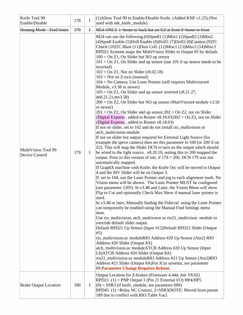
Knife Tool 99 Enable/Disable 178 I (1)Allow Tool 99 to Enable/Disable Knife. (Added KNF v1.25) (Not
used with mh_knife_module) Homing Mode - Find limits 179 I M54 ONLY 1=home to back but set 0,0 at front 0=home to front
MultiVision Tool 99 Device Control 179 I
M24 can use the following.(0)Spndl1 (1)Mist1 (2)Spndl2 (3)Mist2 (4)Spndl Enable (5)Drill Enable (6)Drill1 (7)Drill2 (8)Caution (9)TC Chuck (10)TC Blast (11)Dust Coll. (12)Misc1 (13)Misc2 (14)Misc3 RPD21 Systems maps the MultiVision Slider to Output #5 by default. 100 = On Z1, On Slider but NO up sensor 101 = On Z1, On Slider and up sensor (use 105 if up sensor needs to be inverted) 102 = On Z1, Not on Slider (r8.02.18) 103 = Not on Z-axis (manual) 104 = No Camera, Use Laser Pointer (still requires Multivision4 Module, v3.38 or newer) 105 = On Z1, On Slider and up sensor inverted (r8.21.27, de8.21.21,mv3.58) 200 = On Z2, On Slider but NO up sensor (MutiVision4 module v3.50 or newer) 201 = On Z2, On Slider and up sensor.202 = On Z2, not on Slider (Digital Express , added to Router v8.18.03)302 = On Z3, not on Slider (Digital Express , added to Router v8.18.03) If not on slider, set to 102 and do not install rio_multivision or atcb_multivision module If not on slider but output required for External Light Source (for example the ipevo camera) then set this parameter to 100 (or 200 if on Z2). This will map the Slider DCN to turn on the output which should be wired to the light source. v8.20.19, setting this to 200 mapped the output. Prior to this version of init, if 179 = 200, DCN 179 was not automatically mapped. If GraphX machine with Knife, the Knife Osc will be moved to Output 4 and the MV Slider will be on Output 5. If set to 104, use the Laser Pointer and jog to each alignment mark. No Vision menu will be shown. The Laser Pointer MUST be configured (see parameter 1205). In v3.48 and Later, the Vision Menu will show Flip to Cut and optionally Check Max Skew if manual laser pointer is used. In v3.48 or later, Manually finding the Fiducial using the Laser Pointer can temporarily be enabled using the Manual Find Settings menu item. Use rio_multivision, atcb_multivsion or rio21_multivison module to override default slider output. Default RPD21 Up Sensor (Input #12)Default RPD21 Slider (Output #5) rio_multivision.uc moduleRIO Address #20 Up Sensor (Ain2) RIO Address #20 Slider (Output 8A) atcb_multivision.uc moduleATCB Address #20 Up Sensor (Input L6)ATCB Address #20 Slider (Output 8A) rio21_multivision.uc moduleRIO Address #21 Up Sensor (Ain2)RIO Address #21 Slider (Output 8A)For ICut systems, see parameter 69.Parameter Change Requires Reboot.
Brake Output Location 180 I
Output Location for Z-brakes (Firmware 4.44d, Init V8.02) RPD21 (1) = PNP Output 1 (Pin 21 External I/O) HP4/HP5 (8) = SSR3 (if knife_module, see parameter 600) RPD45 (1) =Relay NC Contact, 2=SSR3(NOTE: Moved from param 189 due to conflict with RIO Table Vac)
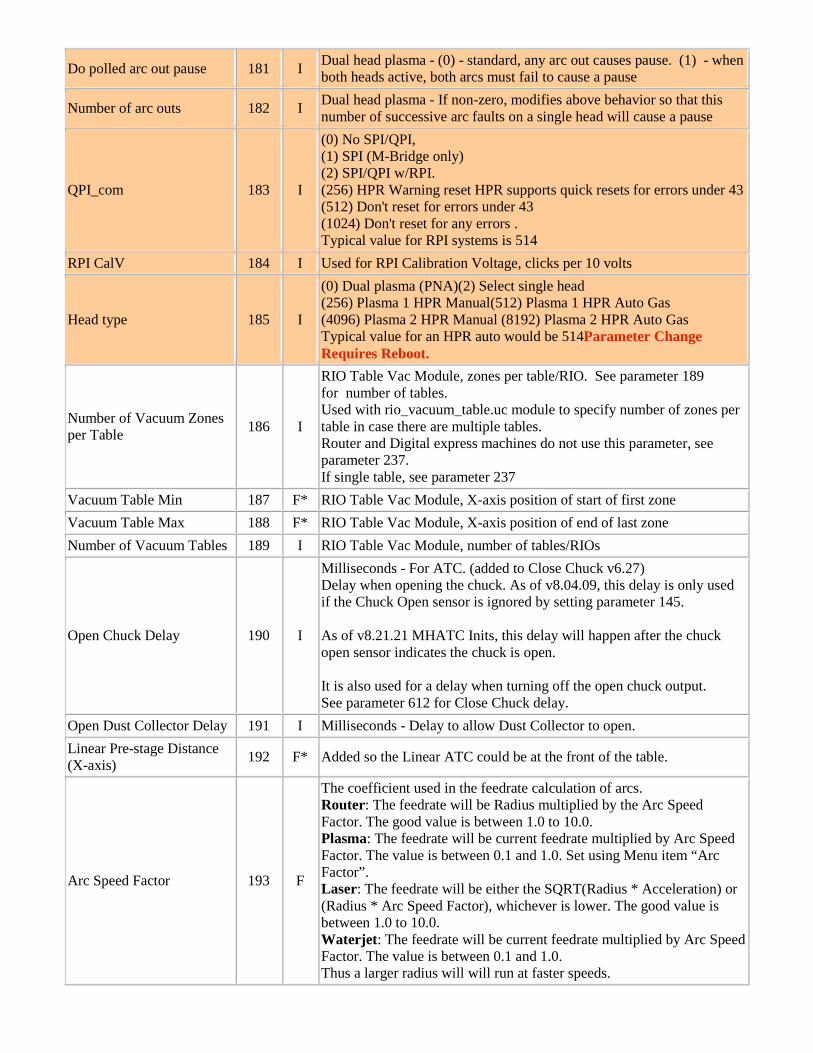
Do polled arc out pause 181 I Dual head plasma - (0) - standard, any arc out causes pause. (1) - when both heads active, both arcs must fail to cause a pause
Number of arc outs 182 I Dual head plasma - If non-zero, modifies above behavior so that this number of successive arc faults on a single head will cause a pause
QPI_com 183 I
(0) No SPI/QPI, (1) SPI (M-Bridge only) (2) SPI/QPI w/RPI. (256) HPR Warning reset HPR supports quick resets for errors under 43 (512) Don't reset for errors under 43 (1024) Don't reset for any errors . Typical value for RPI systems is 514
RPI CalV 184 I Used for RPI Calibration Voltage, clicks per 10 volts
Head type 185 I
(0) Dual plasma (PNA)(2) Select single head (256) Plasma 1 HPR Manual(512) Plasma 1 HPR Auto Gas (4096) Plasma 2 HPR Manual (8192) Plasma 2 HPR Auto Gas Typical value for an HPR auto would be 514Parameter Change Requires Reboot.
Number of Vacuum Zones per Table 186 I
RIO Table Vac Module, zones per table/RIO. See parameter 189 for number of tables. Used with rio_vacuum_table.uc module to specify number of zones per table in case there are multiple tables. Router and Digital express machines do not use this parameter, see parameter 237. If single table, see parameter 237
Vacuum Table Min 187 F* RIO Table Vac Module, X-axis position of start of first zone Vacuum Table Max 188 F* RIO Table Vac Module, X-axis position of end of last zone Number of Vacuum Tables 189 I RIO Table Vac Module, number of tables/RIOs
Open Chuck Delay 190 I
Milliseconds - For ATC. (added to Close Chuck v6.27) Delay when opening the chuck. As of v8.04.09, this delay is only used if the Chuck Open sensor is ignored by setting parameter 145. As of v8.21.21 MHATC Inits, this delay will happen after the chuck open sensor indicates the chuck is open. It is also used for a delay when turning off the open chuck output. See parameter 612 for Close Chuck delay.
Open Dust Collector Delay 191 I Milliseconds - Delay to allow Dust Collector to open. Linear Pre-stage Distance (X-axis) 192 F* Added so the Linear ATC could be at the front of the table.
Arc Speed Factor 193 F
The coefficient used in the feedrate calculation of arcs. Router: The feedrate will be Radius multiplied by the Arc Speed Factor. The good value is between 1.0 to 10.0. Plasma: The feedrate will be current feedrate multiplied by Arc Speed Factor. The value is between 0.1 and 1.0. Set using Menu item “Arc Factor”. Laser: The feedrate will be either the SQRT(Radius * Acceleration) or (Radius * Arc Speed Factor), whichever is lower. The good value is between 1.0 to 10.0. Waterjet: The feedrate will be current feedrate multiplied by Arc Speed Factor. The value is between 0.1 and 1.0. Thus a larger radius will will run at faster speeds.
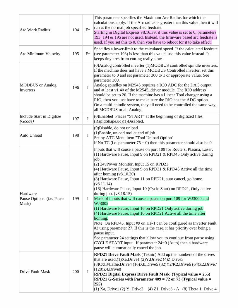
Arc Work Radius 194 F*
This parameter specifies the Maximum Arc Radius for which the calculations apply. If the Arc radius is greater than this value then it will run at the normal job specified feedrate. Starting in Digital Express v8.16.39, if this value is set to 0, parameters 193, 194 & 195 are not used. Instead, the firmware based arc feedrate is used. If you set this to 0, then you have to reboot for it to take effect.
Arc Minimum Velocity 195 F* Specifies a lower-limit to the calculated speed. If the calculated feedrate (see parameter 193) is less than this value, use this value instead. It keeps tiny arcs from cutting really slow.
MODBUS or Analog Inverters 196 I
(0)Analog controlled inverter (1)MODBUS controlled spindle inverters. If the machine does not have a MODBUS Controlled inverter, set this parameter to 0 and set parameter 300 to 1 or appropriate value. See parameter 300. Analog spindles on M2545 requires a RIO ADC for the DAC output and at least v1.40 of the M2545_driver module. The RIO address should be set to 20. If the machine has a Linear Tool changer using a RIO, then you just have to make sure the RIO has the ADC option. On a multi-spindle system, they all need to be controlled the same way, all MODBUS or all Analog.
Include Start in Digitize (Gcode) 197 I (0)Enabled Places “START” at the beginning of digitized files.
(RapidShape.uc)(1)Disabled.
Auto Unload 198 I
(0)Disable, do not unload. (1)Enable, unload tool at end of job Set by ATC Menu item "Tool Unload Option" if No TC (i.e. parameter 75 = 0) then this parameter should also be 0.
Hardware Pause Options (i.e. Pause Mask)
199 I
Inputs that will cause a pause on port 109 for Routers, Plasma, Laser. (1) Hardware Pause, Input 9 on RPD21 & RPD45 Only active during job. (2) 24vPower Monitor, Input 15 on RPD21 (4) Hardware Pause, Input 9 on RPD21 & RPD45 Active all the time after homing (v8.10.20) (8) Hardware Pause, Input 11 on RPD21, auto cancel, go home. (v8.11.14) (16) Hardware Pause, Input 10 (Cycle Start) on RPD21, Only active during job. (v8.18.15) Mask of inputs that will cause a pause on port 109 for WJ3000 and WJ3005 (1) Hardware Pause, Input 16 on RPD21 Only active during job (4) Hardware Pause, Input 16 on RPD21 Active all the time after homing. Note: On RPD45, Input #9 on HF-1 can be configured as Inverter Fault #2 using parameter 27. If this is the case, it has priority over being a pause input. See parameter 24 settings that allow you to continue from pause using CYCLE START input. If parameter 24=0 (Auto) then a hardware pause will automatically cancel the job.
Drive Fault Mask 200 I
RPD21 Drive Fault Mask (Teknic) Add up the numbers of the drives that are used.(1)Xa,Drive1 (2)Y,Drive2 (4)Z,Drive3 (8)C/Z3/Lathe,Drive4 (16)Xb,Drive5 (32)Y2/K2,Drive6 (64)Z2,Drive7 (128)Z4,Drive8 RPD21 Digital Express Drive Fault Mask (Typical value = 255) RPD21 G-Series with Parameter 409 = 72 or 73 (Typical value = 255) (1) Xa, Drive1 (2) Y, Drive2 (4) Z1, Drive3 - A (8) Theta 1, Drive 4
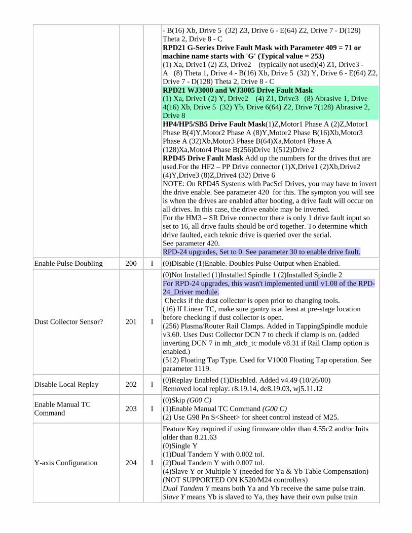
- B(16) Xb, Drive 5 (32) Z3, Drive 6 - E(64) Z2, Drive 7 - D(128) Theta 2, Drive 8 - C RPD21 G-Series Drive Fault Mask with Parameter 409 = 71 or machine name starts with 'G' (Typical value = 253) (1) Xa, Drive1 (2) Z3, Drive2 (typically not used)(4) Z1, Drive3 - A (8) Theta 1, Drive 4 - B(16) Xb, Drive 5 (32) Y, Drive 6 - E(64) Z2, Drive 7 - D(128) Theta 2, Drive 8 - C RPD21 WJ3000 and WJ3005 Drive Fault Mask (1) Xa, Drive1 (2) Y, Drive2 (4) Z1, Drive3 (8) Abrasive 1, Drive 4(16) Xb, Drive 5 (32) Yb, Drive 6(64) Z2, Drive 7(128) Abrasive 2, Drive 8 HP4/HP5/SB5 Drive Fault Mask(1)Z,Motor1 Phase A (2)Z,Motor1 Phase B(4)Y,Motor2 Phase A (8)Y,Motor2 Phase B(16)Xb,Motor3 Phase A (32)Xb,Motor3 Phase B(64)Xa,Motor4 Phase A (128)Xa,Motor4 Phase B(256)Drive 1(512)Drive 2 RPD45 Drive Fault Mask Add up the numbers for the drives that are used.For the HF2 – PP Drive connector (1)X,Drive1 (2)Xb,Drive2 (4)Y,Drive3 (8)Z,Drive4 (32) Drive 6 NOTE: On RPD45 Systems with PacSci Drives, you may have to invert the drive enable. See parameter 420 for this. The sympton you will see is when the drives are enabled after booting, a drive fault will occur on all drives. In this case, the drive enable may be inverted. For the HM3 – SR Drive connector there is only 1 drive fault input so set to 16, all drive faults should be or'd together. To determine which drive faulted, each teknic drive is queried over the serial. See parameter 420. RPD-24 upgrades, Set to 0. See parameter 30 to enable drive fault.
Enable Pulse Doubling 200 I (0)Disable (1)Enable. Doubles Pulse Output when Enabled.
Dust Collector Sensor? 201 I
(0)Not Installed (1)Installed Spindle 1 (2)Installed Spindle 2 For RPD-24 upgrades, this wasn't implemented until v1.08 of the RPD-24_Driver module. Checks if the dust collector is open prior to changing tools. (16) If Linear TC, make sure gantry is at least at pre-stage location before checking if dust collector is open. (256) Plasma/Router Rail Clamps. Added in TappingSpindle module v3.60. Uses Dust Collector DCN 7 to check if clamp is on. (added inverting DCN 7 in mh_atcb_tc module v8.31 if Rail Clamp option is enabled.) (512) Floating Tap Type. Used for V1000 Floating Tap operation. See parameter 1119.
Disable Local Replay 202 I (0)Replay Enabled (1)Disabled. Added v4.49 (10/26/00) Removed local replay: r8.19.14, de8.19.03, wj5.11.12
Enable Manual TC Command 203 I
(0)Skip (G00 C) (1)Enable Manual TC Command (G00 C) (2) Use G98 Pn S<Sheet> for sheet control instead of M25.
Y-axis Configuration 204 I
Feature Key required if using firmware older than 4.55c2 and/or Inits older than 8.21.63 (0)Single Y (1)Dual Tandem Y with 0.002 tol. (2)Dual Tandem Y with 0.007 tol. (4)Slave Y or Multiple Y (needed for Ya & Yb Table Compensation) (NOT SUPPORTED ON K520/M24 controllers) Dual Tandem Y means both Ya and Yb receive the same pulse train. Slave Y means Yb is slaved to Ya, they have their own pulse train
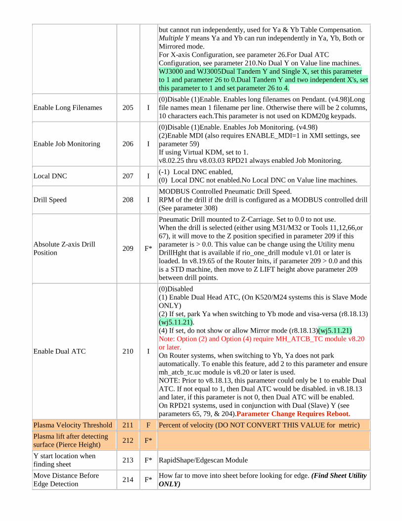
but cannot run independently, used for Ya & Yb Table Compensation. Multiple Y means Ya and Yb can run independently in Ya, Yb, Both or Mirrored mode. For X-axis Configuration, see parameter 26.For Dual ATC Configuration, see parameter 210.No Dual Y on Value line machines. WJ3000 and WJ3005Dual Tandem Y and Single X, set this parameter to 1 and parameter 26 to 0.Dual Tandem Y and two independent X's, set this parameter to 1 and set parameter 26 to 4.
Enable Long Filenames 205 I (0)Disable (1)Enable. Enables long filenames on Pendant. (v4.98)Long file names mean 1 filename per line. Otherwise there will be 2 columns, 10 characters each.This parameter is not used on KDM20g keypads.
Enable Job Monitoring 206 I
(0)Disable (1)Enable. Enables Job Monitoring. (v4.98) (2)Enable MDI (also requires ENABLE_MDI=1 in XMI settings, see parameter 59) If using Virtual KDM, set to 1. v8.02.25 thru v8.03.03 RPD21 always enabled Job Monitoring.
Local DNC 207 I (-1) Local DNC enabled, (0) Local DNC not enabled.No Local DNC on Value line machines.
Drill Speed 208 I MODBUS Controlled Pneumatic Drill Speed. RPM of the drill if the drill is configured as a MODBUS controlled drill (See parameter 308)
Absolute Z-axis Drill Position 209 F*
Pneumatic Drill mounted to Z-Carriage. Set to 0.0 to not use. When the drill is selected (either using M31/M32 or Tools 11,12,66,or 67), it will move to the Z position specified in parameter 209 if this parameter is > 0.0. This value can be change using the Utility menu DrillHght that is available if rio_one_drill module v1.01 or later is loaded. In v8.19.65 of the Router Inits, if parameter 209 > 0.0 and this is a STD machine, then move to Z LIFT height above parameter 209 between drill points.
Enable Dual ATC 210 I
(0)Disabled (1) Enable Dual Head ATC, (On K520/M24 systems this is Slave Mode ONLY) (2) If set, park Ya when switching to Yb mode and visa-versa (r8.18.13) (wj5.11.21). (4) If set, do not show or allow Mirror mode (r8.18.13)(wj5.11.21) Note: Option (2) and Option (4) require MH_ATCB_TC module v8.20 or later. On Router systems, when switching to Yb, Ya does not park automatically. To enable this feature, add 2 to this parameter and ensure mh_atcb_tc.uc module is v8.20 or later is used. NOTE: Prior to v8.18.13, this parameter could only be 1 to enable Dual ATC. If not equal to 1, then Dual ATC would be disabled. in v8.18.13 and later, if this parameter is not 0, then Dual ATC will be enabled. On RPD21 systems, used in conjunction with Dual (Slave) Y (see parameters 65, 79, & 204).Parameter Change Requires Reboot.
Plasma Velocity Threshold 211 F Percent of velocity (DO NOT CONVERT THIS VALUE for metric) Plasma lift after detecting surface (Pierce Height) 212 F*
Y start location when finding sheet 213 F* RapidShape/Edgescan Module
Move Distance Before Edge Detection 214 F* How far to move into sheet before looking for edge. (Find Sheet Utility
ONLY)
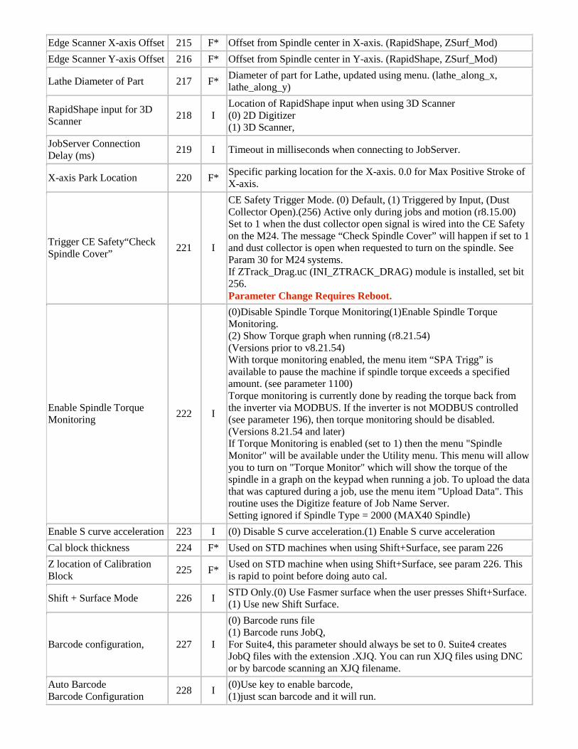
Edge Scanner X-axis Offset 215 F* Offset from Spindle center in X-axis. (RapidShape, ZSurf_Mod) Edge Scanner Y-axis Offset 216 F* Offset from Spindle center in Y-axis. (RapidShape, ZSurf_Mod)
Lathe Diameter of Part 217 F* Diameter of part for Lathe, updated using menu. (lathe_along_x, lathe_along_y)
RapidShape input for 3D Scanner 218 I
Location of RapidShape input when using 3D Scanner (0) 2D Digitizer (1) 3D Scanner,
JobServer Connection Delay (ms) 219 I Timeout in milliseconds when connecting to JobServer.
X-axis Park Location 220 F* Specific parking location for the X-axis. 0.0 for Max Positive Stroke of X-axis.
Trigger CE Safety“Check Spindle Cover” 221 I
CE Safety Trigger Mode. (0) Default, (1) Triggered by Input, (Dust Collector Open).(256) Active only during jobs and motion (r8.15.00) Set to 1 when the dust collector open signal is wired into the CE Safety on the M24. The message “Check Spindle Cover” will happen if set to 1 and dust collector is open when requested to turn on the spindle. See Param 30 for M24 systems. If ZTrack_Drag.uc (INI_ZTRACK_DRAG) module is installed, set bit 256. Parameter Change Requires Reboot.
Enable Spindle Torque Monitoring 222 I
(0)Disable Spindle Torque Monitoring(1)Enable Spindle Torque Monitoring. (2) Show Torque graph when running (r8.21.54) (Versions prior to v8.21.54) With torque monitoring enabled, the menu item “SPA Trigg” is available to pause the machine if spindle torque exceeds a specified amount. (see parameter 1100) Torque monitoring is currently done by reading the torque back from the inverter via MODBUS. If the inverter is not MODBUS controlled (see parameter 196), then torque monitoring should be disabled. (Versions 8.21.54 and later) If Torque Monitoring is enabled (set to 1) then the menu "Spindle Monitor" will be available under the Utility menu. This menu will allow you to turn on "Torque Monitor" which will show the torque of the spindle in a graph on the keypad when running a job. To upload the data that was captured during a job, use the menu item "Upload Data". This routine uses the Digitize feature of Job Name Server. Setting ignored if Spindle Type = 2000 (MAX40 Spindle)
Enable S curve acceleration 223 I (0) Disable S curve acceleration.(1) Enable S curve acceleration Cal block thickness 224 F* Used on STD machines when using Shift+Surface, see param 226 Z location of Calibration Block 225 F* Used on STD machine when using Shift+Surface, see param 226. This
is rapid to point before doing auto cal.
Shift + Surface Mode 226 I STD Only.(0) Use Fasmer surface when the user presses Shift+Surface. (1) Use new Shift Surface.
Barcode configuration, 227 I
(0) Barcode runs file (1) Barcode runs JobQ, For Suite4, this parameter should always be set to 0. Suite4 creates JobQ files with the extension .XJQ. You can run XJQ files using DNC or by barcode scanning an XJQ filename.
Auto Barcode Barcode Configuration 228 I (0)Use key to enable barcode,
(1)just scan barcode and it will run.
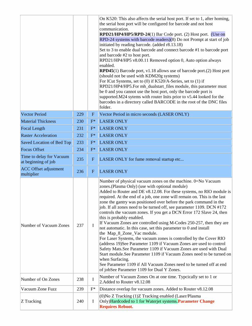
On K520: This also affects the serial host port. If set to 1, after homing, the serial host port will be configured for barcode and not host communication. RPD21/HP4/HP5/RPD-24(1) Bar Code port. (2) Host port. (Use on RPD-24 systems with barcode readers)(8) Do not Prompt at start of job initiated by reading barcode. (added r8.13.18) Set to 3 to enable dual barcode and connect barcode #1 to barcode port and barcode #2 to host port. RPD21/HP4/HP5 v8.00.11 Removed option 0, Auto option always enabled. RPD45(1) Barcode port, v1.18 allows use of barcode port.(2) Host port (should not be used with KDM20g systems) For ICut Systems, set to (0) if K520/A-Series, set to (1) if RPD21/HP4/HP5.For mh_dualstart_files module, this parameter must be 0 and you cannot use the host port, only the barcode port is supported.M24 sytems with router Inits prior to v5.44 looked for the barcodes in a directory called BARCODE in the root of the DNC files folder.
Vector Period 229 F Vector Period in micro seconds (LASER ONLY) Material Thickness 230 F* LASER ONLY Focal Length 231 F* LASER ONLY Raster Acceleration 232 F* LASER ONLY Saved Location of Bed Top 233 F* LASER ONLY Focus Offset 234 F* LASER ONLY Time to delay for Vacuum at beginning of job 235 F LASER ONLY for fume removal startup etc...
ACC Offset adjustment multiplier 236 F LASER ONLY
Number of Vacuum Zones 237 I
Number of physical vacuum zones on the machine. 0=No Vacuum zones.(Plasma Only) (use with optional module) Added to Router and DE v8.12.08. For these systems, no RIO module is required. At the end of a job, one zone will remain on. This is the last zone the gantry was positioned over before the park command in the job. If all zones need to be turned off, see parameter 1109. DCN #172 controls the vacuum zones. If you get a DCN Error 172 Slave 24, then this is probably enabled. If Vacuum Zones are controlled using M-Codes 250-257, then they are not automatic. In this case, set this parameter to 0 and install the Map_8_Zone_Vac module. For Laser Systems, the vacuum zones is controlled by the Cover RIO (address 19)See Parameter 1109 if Vacuum Zones are used to control Safety Mats.See Parameter 1109 if Vacuum Zones are used with Dual Start module.See Parameter 1109 if Vacuum Zones need to be turned on when Surfacing. See Parameter 1109 if All Vacuum Zones need to be turned off at end of jobSee Parameter 1109 for Dual Y Zones.
Number of On Zones 238 I Number of Vacuum Zones On at one time. Typcically set to 1 or 2.Added to Router v8.12.08
Vacuum Zone Fuzz 239 F* Distance overlap for vacuum zones. Added to Router v8.12.08
Z Tracking 240 I (0)No Z Tracking (1)Z Tracking enabled (Laser/Plasma Only)Hardcoded to 1 for Waterjet systems.Parameter Change Requires Reboot.
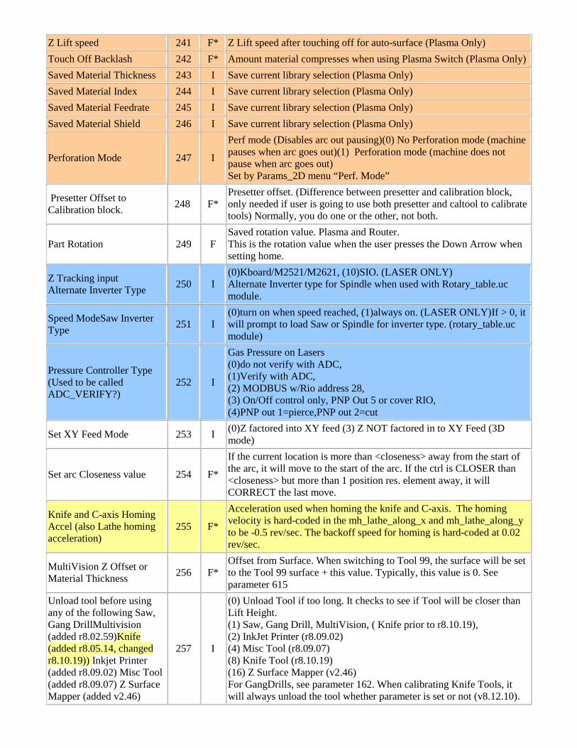
Z Lift speed 241 F* Z Lift speed after touching off for auto-surface (Plasma Only) Touch Off Backlash 242 F* Amount material compresses when using Plasma Switch (Plasma Only) Saved Material Thickness 243 I Save current library selection (Plasma Only) Saved Material Index 244 I Save current library selection (Plasma Only) Saved Material Feedrate 245 I Save current library selection (Plasma Only) Saved Material Shield 246 I Save current library selection (Plasma Only)
Perforation Mode 247 I
Perf mode (Disables arc out pausing)(0) No Perforation mode (machine pauses when arc goes out)(1) Perforation mode (machine does not pause when arc goes out) Set by Params_2D menu “Perf. Mode”
Presetter Offset to Calibration block. 248 F*
Presetter offset. (Difference between presetter and calibration block, only needed if user is going to use both presetter and caltool to calibrate tools) Normally, you do one or the other, not both.
Part Rotation 249 F Saved rotation value. Plasma and Router. This is the rotation value when the user presses the Down Arrow when setting home.
Z Tracking input Alternate Inverter Type 250 I
(0)Kboard/M2521/M2621, (10)SIO. (LASER ONLY) Alternate Inverter type for Spindle when used with Rotary_table.uc module.
Speed ModeSaw Inverter Type 251 I
(0)turn on when speed reached, (1)always on. (LASER ONLY)If > 0, it will prompt to load Saw or Spindle for inverter type. (rotary_table.uc module)
Pressure Controller Type (Used to be called ADC_VERIFY?)
252 I
Gas Pressure on Lasers (0)do not verify with ADC, (1)Verify with ADC, (2) MODBUS w/Rio address 28, (3) On/Off control only, PNP Out 5 or cover RIO, (4)PNP out 1=pierce,PNP out 2=cut
Set XY Feed Mode 253 I (0)Z factored into XY feed (3) Z NOT factored in to XY Feed (3D mode)
Set arc Closeness value 254 F*
If the current location is more than <closeness> away from the start of the arc, it will move to the start of the arc. If the ctrl is CLOSER than <closeness> but more than 1 position res. element away, it will CORRECT the last move.
Knife and C-axis Homing Accel (also Lathe homing acceleration)
255 F*
Acceleration used when homing the knife and C-axis. The homing velocity is hard-coded in the mh_lathe_along_x and mh_lathe_along_y to be -0.5 rev/sec. The backoff speed for homing is hard-coded at 0.02 rev/sec.
MultiVision Z Offset or Material Thickness 256 F*
Offset from Surface. When switching to Tool 99, the surface will be set to the Tool 99 surface + this value. Typically, this value is 0. See parameter 615
Unload tool before using any of the following Saw, Gang DrillMultivision (added r8.02.59)Knife (added r8.05.14, changed r8.10.19)) Inkjet Printer (added r8.09.02) Misc Tool (added r8.09.07) Z Surface Mapper (added v2.46)
257 I
(0) Unload Tool if too long. It checks to see if Tool will be closer than Lift Height. (1) Saw, Gang Drill, MultiVision, ( Knife prior to r8.10.19), (2) InkJet Printer (r8.09.02) (4) Misc Tool (r8.09.07) (8) Knife Tool (r8.10.19) (16) Z Surface Mapper (v2.46) For GangDrills, see parameter 162. When calibrating Knife Tools, it will always unload the tool whether parameter is set or not (v8.12.10).
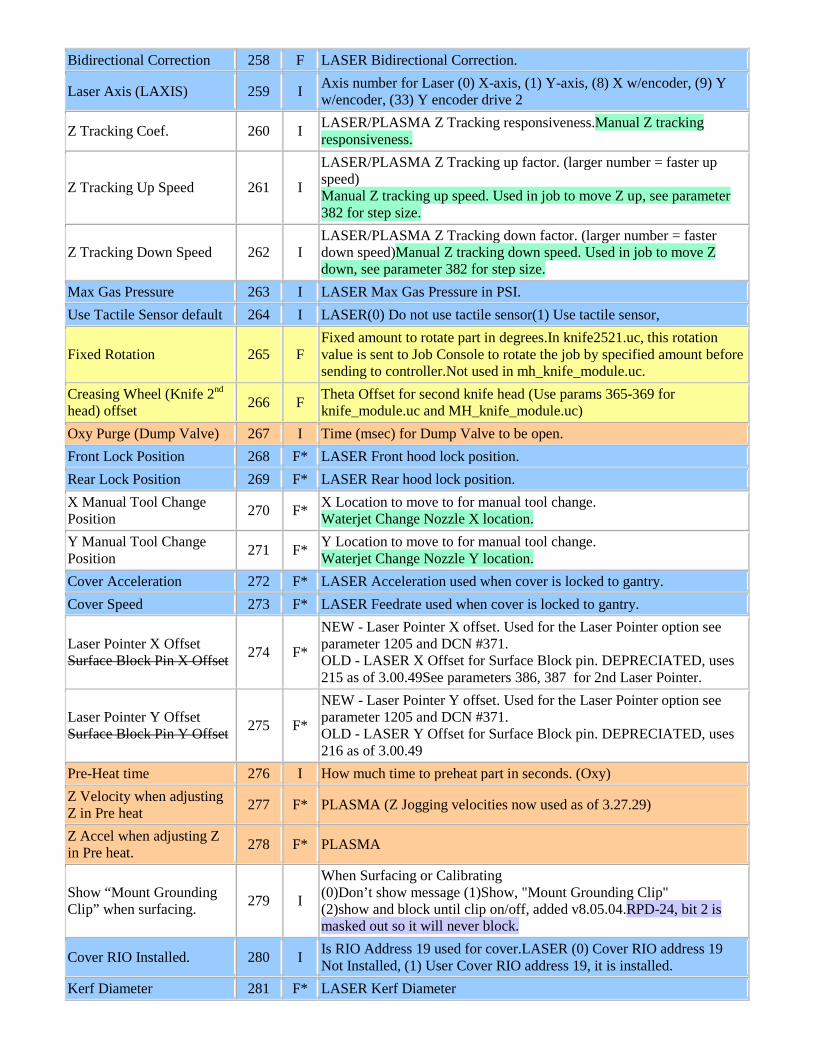
Bidirectional Correction 258 F LASER Bidirectional Correction.
Laser Axis (LAXIS) 259 I Axis number for Laser (0) X-axis, (1) Y-axis, (8) X w/encoder, (9) Y w/encoder, (33) Y encoder drive 2
Z Tracking Coef. 260 I LASER/PLASMA Z Tracking responsiveness.Manual Z tracking responsiveness.
Z Tracking Up Speed 261 I
LASER/PLASMA Z Tracking up factor. (larger number = faster up speed) Manual Z tracking up speed. Used in job to move Z up, see parameter 382 for step size.
Z Tracking Down Speed 262 I LASER/PLASMA Z Tracking down factor. (larger number = faster down speed)Manual Z tracking down speed. Used in job to move Z down, see parameter 382 for step size.
Max Gas Pressure 263 I LASER Max Gas Pressure in PSI. Use Tactile Sensor default 264 I LASER(0) Do not use tactile sensor(1) Use tactile sensor,
Fixed Rotation 265 F Fixed amount to rotate part in degrees.In knife2521.uc, this rotation value is sent to Job Console to rotate the job by specified amount before sending to controller.Not used in mh_knife_module.uc.
Creasing Wheel (Knife 2nd head) offset 266 F Theta Offset for second knife head (Use params 365-369 for
knife_module.uc and MH_knife_module.uc) Oxy Purge (Dump Valve) 267 I Time (msec) for Dump Valve to be open. Front Lock Position 268 F* LASER Front hood lock position. Rear Lock Position 269 F* LASER Rear hood lock position. X Manual Tool Change Position 270 F* X Location to move to for manual tool change.
Waterjet Change Nozzle X location. Y Manual Tool Change Position 271 F* Y Location to move to for manual tool change.
Waterjet Change Nozzle Y location. Cover Acceleration 272 F* LASER Acceleration used when cover is locked to gantry. Cover Speed 273 F* LASER Feedrate used when cover is locked to gantry.
Laser Pointer X Offset Surface Block Pin X Offset 274 F*
NEW - Laser Pointer X offset. Used for the Laser Pointer option see parameter 1205 and DCN #371. OLD - LASER X Offset for Surface Block pin. DEPRECIATED, uses 215 as of 3.00.49See parameters 386, 387 for 2nd Laser Pointer.
Laser Pointer Y Offset Surface Block Pin Y Offset 275 F*
NEW - Laser Pointer Y offset. Used for the Laser Pointer option see parameter 1205 and DCN #371. OLD - LASER Y Offset for Surface Block pin. DEPRECIATED, uses 216 as of 3.00.49
Pre-Heat time 276 I How much time to preheat part in seconds. (Oxy) Z Velocity when adjusting Z in Pre heat 277 F* PLASMA (Z Jogging velocities now used as of 3.27.29)
Z Accel when adjusting Z in Pre heat. 278 F* PLASMA
Show “Mount Grounding Clip” when surfacing. 279 I
When Surfacing or Calibrating (0)Don’t show message (1)Show, "Mount Grounding Clip" (2)show and block until clip on/off, added v8.05.04.RPD-24, bit 2 is masked out so it will never block.
Cover RIO Installed. 280 I Is RIO Address 19 used for cover.LASER (0) Cover RIO address 19 Not Installed, (1) User Cover RIO address 19, it is installed.
Kerf Diameter 281 F* LASER Kerf Diameter
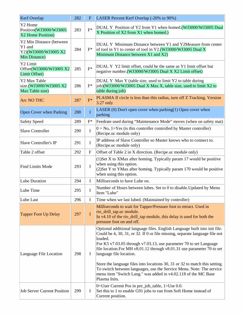
Kerf Overlap 282 F LASER Percent Kerf Overlap (-20% to 90%) Y2 Home Position(WJ3000/WJ3005 X2 Home Position)
283 F* DUAL Y Position of Y2 from Y1 when homed.(WJ3000/WJ3005 Dual X Position of X2 from X1 when homed.)
Y2 Min Distance (between Y1 and Y2)(WJ3000/WJ3005 X2 Min Distance)
284 F* DUAL Y Minimum Distance between Y1 and Y2Measure from center of tool in Y1 to center of tool in Y2.(WJ3000/WJ3005 Dual X Minimum Distance between X1 and X2)
Y2 Limit Offset(WJ3000/WJ3005 X2 Limit Offset)
285 F* DUAL Y Y2 limit offset, could be the same as Y1 limit offset but negative number.(WJ3000/WJ3005 Dual X X2 Limit offset)
Y2 Max Table size.(WJ3000/WJ3005 X2 Max Table size)
286 F* DUAL Y Max Y (table size, used to limit Y2 to table during job)(WJ3000/WJ3005 Dual X Max X, table size, used to limit X2 to table during job)
Arc NO THC 287 F* PLASMA If circle is less than this radius, turn off Z Tracking. Version 3.27 only
Open Cover when Parking 288 I LASER (0) Don't open cover when parking(1) Open cover when parking
Safety Speed 289 F* Feedrate used during “Maintenance Mode” moves (when on safety mat)
Slave Controller 290 I 0 = No, 1=Yes (is this controller controlled by Master controller) (Recipe.uc module only)
Slave Controller's IP 291 I IP address of Slave Controller so Master knows who to connect to. (Recipe.uc module only)
Table 2 offset 292 F Offset of Table 2 in X direction. (Recipe.uc module only)
Find Limits Mode 293 I
(1)Set X to XMax after homing. Typically param 17 would be positive when using this option. (2)Set Y to YMax after homing. Typically param 170 would be positive when using this option.
Lube Duration 294 I Milliseconds to have Lube on.
Lube Time 295 I Number of Hours between lubes. Set to 0 to disable.Updated by Menu Item "Lube"
Lube Last 296 I Time when we last lubed. (Maintained by controller)
Tapper Foot Up Delay 297 I
Milliseconds to wait for Tapper/Pressure foot to retract. Used in rio_drill_tap.uc module. In v4.10 of the rio_drill_tap module, this delay is used for both the pressure foot on and off.
Language File Location 298 I
Optional additional language files. English Language built into init file. Could be 4, 30, 31, or 32. If 0 or file missing, separate language file not loaded. For K5 v7.03.05 through v7.03.13, use parameter 70 to set Language file location.For MH v8.01.12 through v8.01.31 use parameter 70 to set language file location. Store the language files into locations 30, 31 or 32 to match this setting. To switch between languages, use the Service Menu. Note: The service menu item "Switch Lang." was added in v4.02.118 of the MC Base Plasma Inits.
Job Server Current Position 299 I 0=User Current Pos in pre_job_table, 1=Use 0.0. Set this to 1 to enable G91 jobs to run from Soft Home instead of Current position.
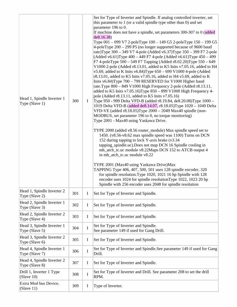
Head 1, Spindle Inverter 1 Type (Slave 1) 300 I
Set for Type of Inverter and Spindle. If analog controlled inverter, set this parameter to 1 (or a valid spindle type other than 0) and set parameter 196 to 0. If machine does not have a spindle, set parameters 300-307 to 0 (added de8.16.38) Type 001 – 099 V7 2-poleType 100 – 149 G5 2-poleType 150 – 199 G5 4-poleType 200 – 299 P5 (no longer supported because of 9600 baud rate)Type 300 – 349 V7 4-pole (Added v6.37)Type 350 – 399 F7 2-pole (Added v6.61)Type 400 – 449 F7 4-pole (Added v6.61)Type 450 – 499 F7 4-poleType 500 – 549 F7 Tapping (Added r8.02.20)Type 550 – 649 V1000 2-pole (Added r8.13.01, added to K5 Inits v7.05.16, added to H4 v5.69, added to K Inits v6.84)Type 650 – 699 V1000 4-pole (Added r8.13.01, added to K5 Inits v7.05.16, added to H4 v5.69, added to K Inits v6.84)Type 700 – 799 RESERVED for V1000 Higher baud rate.Type 800 – 849 V1000 High Frequency 2-pole (Added r8.13.11, added to K5 Inits v7.05.16)Type 850 – 899 V1000 High Frequency 4-pole (Added r8.13.11, added to K5 Inits v7.05.16) Type 950 - 999 Delta VFD-B (added r8.19.84, de8.20.08)Type 1000 – 1019 Delta VFD-B (added de8.14.07, r8.18.05)Type 1020 – 1049 Delta VFD-VE (added r8.18.05)Type 2000 – 2049 Max40 spindle (non-MODBUS, set parameter 196 to 0, no torque monitoring) Type 2001 - Max40 using Yaskawa Drive. TYPE 2000 (added v8.56 router_module) Max spindle speed set to
1450. (v8.56-v8.62 max spindle speed was 1100) Turns on DCN 152 during tapping to lock Y-axis brake (v3.34 tapping_spindle.uc).Does not map DCN 16 Spindle cooling in mh_atcb_tc.uc module v8.22Maps DCN 152 to ATCB output 4 in mh_atcb_tc.uc module v8.22
TYPE 2001 (Max40 using Yaskawa Drive)Max TAPPING Type 406, 407, 500, 501 uses 128 spindle encoder, 320
for spindle resolution.Type 1020, 1021 16 hp Spindle with 128 encoder uses 1024 for spindle resolutionType 1022, 1023 20 hp Spindle with 256 encoder uses 2048 for spindle resolution
Head 1, Spindle Inverter 2 Type (Slave 2) 301 I Set for Type of Inverter and Spindle.
Head 2, Spindle Inverter 1 Type (Slave 3) 302 I Set for Type of Inverter and Spindle.
Head 2, Spindle Inverter 2 Type (Slave 4) 303 I Set for Type of Inverter and Spindle.
Head 3, Spindle Inverter 1 Type (Slave 5) 304 I Set for Type of Inverter and Spindle.
See parameter 149 if used for Gang Drill. Head 3, Spindle Inverter 2 Type (Slave 6) 305 I Set for Type of Inverter and Spindle.
Head 4, Spindle Inverter 1 Type (Slave 7) 306 I Set for Type of Inverter and Spindle.See parameter 149 if used for Gang
Drill. Head 4, Spindle Inverter 2 Type (Slave 8) 307 I Set for Type of Inverter and Spindle.
Drill 1, Inverter 1 Type (Slave 10) 308 I Set for Type of Inverter and Drill. See parameter 208 to set the drill
RPM. Extra Mod bus Device. (Slave 11) 309 I Type of Inverter.
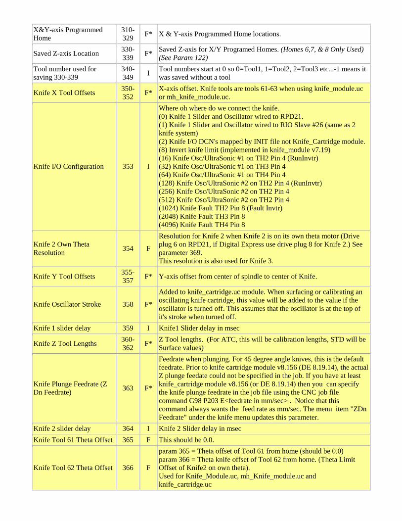
X&Y-axis Programmed Home
310-329 F* X & Y-axis Programmed Home locations.
Saved Z-axis Location 330-339 F* Saved Z-axis for X/Y Programed Homes. (Homes 6,7, & 8 Only Used)
(See Param 122) Tool number used for saving 330-339
340-349 I Tool numbers start at 0 so 0=Tool1, 1=Tool2, 2=Tool3 etc...-1 means it
was saved without a tool
Knife X Tool Offsets 350-352 F* X-axis offset. Knife tools are tools 61-63 when using knife_module.uc
or mh_knife_module.uc.
Knife I/O Configuration 353 I
Where oh where do we connect the knife. (0) Knife 1 Slider and Oscillator wired to RPD21. (1) Knife 1 Slider and Oscillator wired to RIO Slave #26 (same as 2 knife system) (2) Knife I/O DCN's mapped by INIT file not Knife_Cartridge module. (8) Invert knife limit (implemented in knife_module v7.19) (16) Knife Osc/UltraSonic #1 on TH2 Pin 4 (RunInvtr) (32) Knife Osc/UltraSonic #1 on TH3 Pin 4 (64) Knife Osc/UltraSonic #1 on TH4 Pin 4 (128) Knife Osc/UltraSonic #2 on TH2 Pin 4 (RunInvtr) (256) Knife Osc/UltraSonic #2 on TH2 Pin 4 (512) Knife Osc/UltraSonic #2 on TH2 Pin 4 (1024) Knife Fault TH2 Pin 8 (Fault Invtr) (2048) Knife Fault TH3 Pin 8 (4096) Knife Fault TH4 Pin 8
Knife 2 Own Theta Resolution 354 F
Resolution for Knife 2 when Knife 2 is on its own theta motor (Drive plug 6 on RPD21, if Digital Express use drive plug 8 for Knife 2.) See parameter 369. This resolution is also used for Knife 3.
Knife Y Tool Offsets 355-357 F* Y-axis offset from center of spindle to center of Knife.
Knife Oscillator Stroke 358 F*
Added to knife_cartridge.uc module. When surfacing or calibrating an oscillating knife cartridge, this value will be added to the value if the oscillator is turned off. This assumes that the oscillator is at the top of it's stroke when turned off.
Knife 1 slider delay 359 I Knife1 Slider delay in msec
Knife Z Tool Lengths 360-362 F* Z Tool lengths. (For ATC, this will be calibration lengths, STD will be
Surface values)
Knife Plunge Feedrate (Z Dn Feedrate) 363 F*
Feedrate when plunging. For 45 degree angle knives, this is the default feedrate. Prior to knife cartridge module v8.156 (DE 8.19.14), the actual Z plunge feedate could not be specified in the job. If you have at least knife_cartridge module v8.156 (or DE 8.19.14) then you can specify the knife plunge feedrate in the job file using the CNC job file command G98 P203 E<feedrate in mm/sec> . Notice that this command always wants the feed rate as mm/sec. The menu item "ZDn Feedrate" under the knife menu updates this parameter.
Knife 2 slider delay 364 I Knife 2 Slider delay in msec Knife Tool 61 Theta Offset 365 F This should be 0.0.
Knife Tool 62 Theta Offset 366 F
param 365 = Theta offset of Tool 61 from home (should be 0.0) param 366 = Theta knife offset of Tool 62 from home. (Theta Limit Offset of Knife2 on own theta). Used for Knife_Module.uc, mh_Knife_module.uc and knife_cartridge.uc
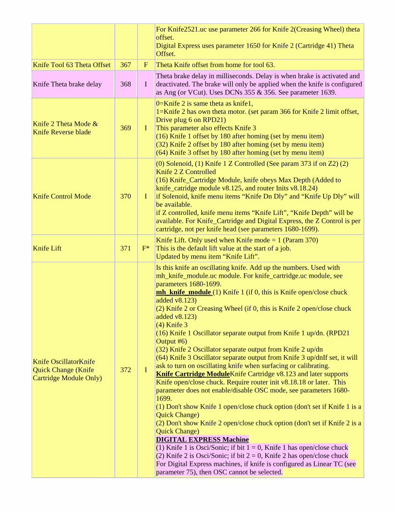
For Knife2521.uc use parameter 266 for Knife 2(Creasing Wheel) theta offset. Digital Express uses parameter 1650 for Knife 2 (Cartridge 41) Theta Offset.
Knife Tool 63 Theta Offset 367 F Theta Knife offset from home for tool 63.
Knife Theta brake delay 368 I Theta brake delay in milliseconds. Delay is when brake is activated and deactivated. The brake will only be applied when the knife is configured as Ang (or VCut). Uses DCNs 355 & 356. See parameter 1639.
Knife 2 Theta Mode & Knife Reverse blade 369 I
0=Knife 2 is same theta as knife1, 1=Knife 2 has own theta motor. (set param 366 for Knife 2 limit offset, Drive plug 6 on RPD21) This parameter also effects Knife 3 (16) Knife 1 offset by 180 after homing (set by menu item) (32) Knife 2 offset by 180 after homing (set by menu item) (64) Knife 3 offset by 180 after homing (set by menu item)
Knife Control Mode 370 I
(0) Solenoid, (1) Knife 1 Z Controlled (See param 373 if on Z2) (2) Knife 2 Z Controlled (16) Knife_Cartridge Module, knife obeys Max Depth (Added to knife_catridge module v8.125, and router Inits v8.18.24) if Solenoid, knife menu items “Knife Dn Dly” and “Knife Up Dly” will be available. if Z controlled, knife menu items “Knife Lift”, “Knife Depth” will be available. For Knife_Cartridge and Digital Express, the Z Control is per cartridge, not per knife head (see parameters 1680-1699).
Knife Lift 371 F* Knife Lift. Only used when Knife mode = 1 (Param 370) This is the default lift value at the start of a job. Updated by menu item “Knife Lift”.
Knife OscillatorKnife Quick Change (Knife Cartridge Module Only)
372 I
Is this knife an oscillating knife. Add up the numbers. Used with mh_knife_module.uc module. For knife_cartridge.uc module, see parameters 1680-1699. mh_knife_module (1) Knife 1 (if 0, this is Knife open/close chuck added v8.123) (2) Knife 2 or Creasing Wheel (if 0, this is Knife 2 open/close chuck added v8.123) (4) Knife 3 (16) Knife 1 Oscillator separate output from Knife 1 up/dn. (RPD21 Output #6) (32) Knife 2 Oscillator separate output from Knife 2 up/dn (64) Knife 3 Oscillator separate output from Knife 3 up/dnIf set, it will ask to turn on oscillating knife when surfacing or calibrating. Knife Cartridge ModuleKnife Cartridge v8.123 and later supports Knife open/close chuck. Require router init v8.18.18 or later. This parameter does not enable/disable OSC mode, see parameters 1680-1699. (1) Don't show Knife 1 open/close chuck option (don't set if Knife 1 is a Quick Change) (2) Don't show Knife 2 open/close chuck option (don't set if Knife 2 is a Quick Change) DIGITAL EXPRESS Machine (1) Knife 1 is Osci/Sonic; if bit 1 = 0, Knife 1 has open/close chuck (2) Knife 2 is Osci/Sonic; if bit 2 = 0, Knife 2 has open/close chuck For Digital Express machines, if knife is configured as Linear TC (see parameter 75), then OSC cannot be selected.

Knife Head Configuration 373 I
Is this knife on Z2 or Z3. (0 ) K1 is on Z1 with slider (knife_cartridge: if dual knife, K2 is also on Z1 with slider, on DE machines, if =0, then K1 is on Z1 and K2 is on Z2. Also used on G-Series machines) (1 ) K1 is on Z2, no slider (2 ) K2 is on Z3, no slider (4 ) K2 is on Z2 (knife_cartridge v8.161) (16 ) Knife assembly on Slider, uses DCN 197 (knife_cartridge v8.124) (32 ) Check Knife assembly Up Sensor, uses DCN 189 (knife_cartridge v8.124) For Digital Express machine, this value should be set to 3 to indicate K1 is on Z2 and K2 is on Z3. For G-Series machines, this parameter is typically set to 0 to indicate K1 is on Z1 and K2 is on Z2. Parameter Change Requires Reboot.
Knife Limit Offset 374 F
Used when homing the knife. (see param 366 for Knife 2 limit offset, see param 367 for Knife 3 limit offset)) Digital Express uses parameter 1640 for Knife 1 (Cartridge 31) Limit Offset.
Knife Cut Depth 375-377 F* Knife cut depth when using Knife_Module.uc. Only used when Knife
Mode = 1 (Param 370)
Knife Z Control 378 I
What specifies the Knife Cut Depth and Lift Height. (0) Keypad (1) G-Code Control of feedrate was added in kc8.94. If set to 1,the Z depth, Lift Height and the Knife Feedrate will be controlled from the Job File.
Number of Knife Heads 379 I
Specify number of Knife heads.Max 3 Knives for mh_knife_module.uc, tools 61, 62 & 63.Max 2 knives for knife_cartridge.uc up to version v8.89, tools 31-40 & 41-50Max 3 knives for knife_cartridge.uc v8.90 and above, tools 31-40, 41-45 & 46-50. See parameter 369 if Knife 2 has it own theta motor that needs to be homed. See parameter 986 for number of knife tools in knife tool changer. See parameter 1720 for number of tools for knife head 1 (added DE.8.18.35). See parameter 1721 for number of tools for knife head 2 (added DE 8.18.35)
Waterjet Options 380 I
(1) Has Abrasive unit (Uses RPD21 TH#1 RunInvtr for on/off) (2) Has Hi/Lo intensifier (Uses RPD21 Output 9) (4) Invert Hi/Lo intensifier (Uses RPD21 TH#1 RunInvtr, Note: This is the same output as Abrasive.) (8) Stores Cut Acceleration in material library without per minute conversion. (16) Does this waterjet have a calibrated abrasive unit. (32) v5.11.05 Set Surface at start of job. With this option, you don't need to set surface before running a job. At the start of a job, the current Z position will be the cut height. (64) v5.11.24 Move to Lift Height after pressing Go Home key. In v5.11.23 and prior, it would always move to lift height after pressing Go Home key. In addition, v5.11.24 will always move to Z=0.0 before moving in X and Y to go home. (128) v5.12 Turn on WJ Pump at start of job.(Used for M2545 when param 600 = 30 or 31) (256) v5.12 Turn off WJ Pump at end of job (Used for M2545 when param 600 = 30 or 31) (512) v5.12.69 Move to Z_LIFT at start of job. v5.12.67. Prior versions would always move to Z lift at the start of the job.
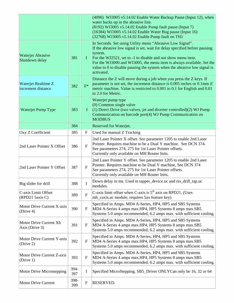
(4096) WJ3005 v5.14.02 Enable Water Backup Pause (Input 12), when water backs up in the abrasive line. (8192) WJ3005 v5.14.02 Enable Pump fault pause (Input 7) (16384) WJ3005 v5.14.02 Enable Water Bug pause (Input 16) (32768) WJ3005 v5.14.02 Enable Pump fault on TH1
Waterjet Abrasive Shutdown delay 381 I
In Seconds. Set using Utility menu “Abrasive Low Signal”. If the abrasive low signal is set, wait for delay specified before pausing system. For the WJ2521, set to -1 to disable and not show menu item. For the WJ3000 and WJ3005, the menu item is always available. Set the value to 0 to disable pausing the system when the abrasive low signal is activated.
Waterjet Realtime Z increment distance 382 F*
Distance the Z will move during a job when you press the Z keys. If parameter is not set, the increment distance is 0.005 inches or 0.1mm if metric machine. Value is restricted to 0.001 to 0.1 for English and 0.01 to 2.0 for Metric.
Waterjet Pump Type 383 I
Waterjet pump type (0) Common single valve (1) Direct Drive (two valves, jet and diverter controlled)(2) WJ Pump Communication on barcode port(4) WJ Pump Communication on MODBUS
384 Reserved for Waterjet. Oxy Z Coefficient 385 F Used for manual Z Tracking
2nd Laser Pointer X Offset 386 F
2nd Laser Pointer X offset. See parameter 1205 to enable 2nd Laser Pointer. Requires machine to be a Dual Y machine. See DCN 374. See parameters 274, 275 for 1st Laser Pointer offsets. Currently only available on MH Router Inits.
2nd Laser Pointer Y Offset 387 F
2nd Laser Pointer Y offset. See parameter 1205 to enable 2nd Laser Pointer. Requires machine to be Dual Y machine, See DCN 374 See parameters 274, 275 for 1st Laser Pointer offsets. Currently only available on MH Router Inits.
Big slider for drill 388 I Down delay in ms. Used in tapper_device.uc and rio_drill_tap.uc modules.
C-axis Limit Offset (RPD21 5axis C) 389 F C-axis limit offset when C-axis is 5th axis on RPD21. (Uses
mh_caxis.uc module, requires 5ax feature key)
Motor Drive Current X-axis (Drive 4) 390 F
Specified in Amps. MD4 A-Series, HP4, HP5 and SB5 Systems MD4 A-Series 4 amps max.HP4, HP5 Systems 8 amps max.SB5 Systems 5.0 amps recommended, 6.2 amps max. with sufficient cooling.
Motor Drive Current Xb Axis (Drive 3) 391 F
Specified in Amps. MD4 A-Series, HP4, HP5 and SB5 Systems MD4 A-Series 4 amps max.HP4, HP5 Systems 8 amps max.SB5 Systems 5.0 amps recommended, 6.2 amps max. with sufficient cooling.
Motor Drive Current Y-axis (Drive 2) 392 F
Specified in Amps. MD4 A-Series, HP4, HP5 and SB5 Systems MD4 A-Series 4 amps max.HP4, HP5 Systems 8 amps max.SB5 Systems 5.0 amps recommended, 6.2 amps max. with sufficient cooling.
Motor Drive Current Z-axis (Drive 1) 393 F
Specified in Amps. MD4 A-Series, HP4, HP5 and SB5 Systems MD4 A-Series 4 amps max.HP4, HP5 Systems 8 amps max.SB5 Systems 5.0 amps recommended, 6.2 amps max. with sufficient cooling.
Motor Drive Microstepping 394-397 I Specified MicroStepping. SB5_Driver ONLYCan only be 16, 32 or 64
Motor Drive Current 398-399 F RESERVED.
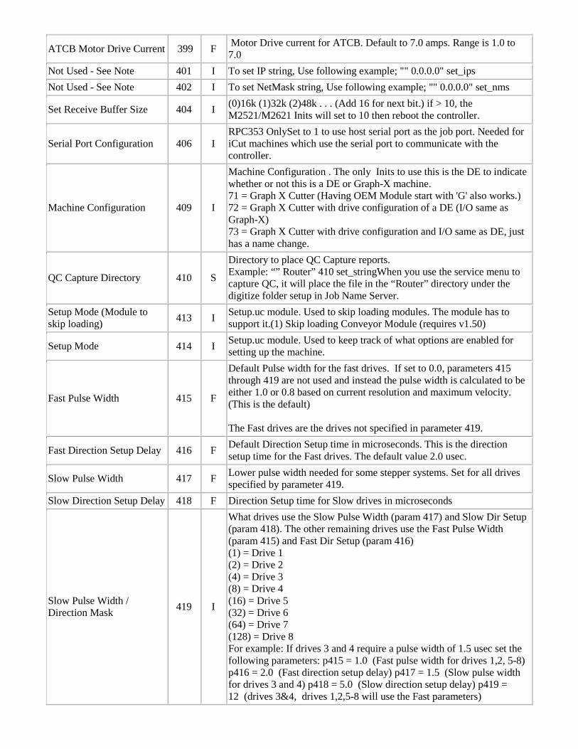
ATCB Motor Drive Current 399 F Motor Drive current for ATCB. Default to 7.0 amps. Range is 1.0 to 7.0
Not Used - See Note 401 I To set IP string, Use following example; "" 0.0.0.0" set_ips Not Used - See Note 402 I To set NetMask string, Use following example; "" 0.0.0.0" set_nms
Set Receive Buffer Size 404 I (0)16k (1)32k (2)48k . . . (Add 16 for next bit.) if > 10, the M2521/M2621 Inits will set to 10 then reboot the controller.
Serial Port Configuration 406 I RPC353 OnlySet to 1 to use host serial port as the job port. Needed for iCut machines which use the serial port to communicate with the controller.
Machine Configuration 409 I
Machine Configuration . The only Inits to use this is the DE to indicate whether or not this is a DE or Graph-X machine. 71 = Graph X Cutter (Having OEM Module start with 'G' also works.) 72 = Graph X Cutter with drive configuration of a DE (I/O same as Graph-X) 73 = Graph X Cutter with drive configuration and I/O same as DE, just has a name change.
QC Capture Directory 410 S
Directory to place QC Capture reports. Example: “” Router” 410 set_stringWhen you use the service menu to capture QC, it will place the file in the “Router” directory under the digitize folder setup in Job Name Server.
Setup Mode (Module to skip loading) 413 I Setup.uc module. Used to skip loading modules. The module has to
support it.(1) Skip loading Conveyor Module (requires v1.50)
Setup Mode 414 I Setup.uc module. Used to keep track of what options are enabled for setting up the machine.
Fast Pulse Width 415 F
Default Pulse width for the fast drives. If set to 0.0, parameters 415 through 419 are not used and instead the pulse width is calculated to be either 1.0 or 0.8 based on current resolution and maximum velocity. (This is the default) The Fast drives are the drives not specified in parameter 419.
Fast Direction Setup Delay 416 F Default Direction Setup time in microseconds. This is the direction setup time for the Fast drives. The default value 2.0 usec.
Slow Pulse Width 417 F Lower pulse width needed for some stepper systems. Set for all drives specified by parameter 419.
Slow Direction Setup Delay 418 F Direction Setup time for Slow drives in microseconds
Slow Pulse Width / Direction Mask 419 I
What drives use the Slow Pulse Width (param 417) and Slow Dir Setup (param 418). The other remaining drives use the Fast Pulse Width (param 415) and Fast Dir Setup (param 416) (1) = Drive 1 (2) = Drive 2 (4) = Drive 3 (8) = Drive 4 (16) = Drive 5 (32) = Drive 6 (64) = Drive 7 (128) = Drive 8 For example: If drives 3 and 4 require a pulse width of 1.5 usec set the following parameters: p415 = 1.0 (Fast pulse width for drives 1,2, 5-8) p416 = 2.0 (Fast direction setup delay) p417 = 1.5 (Slow pulse width for drives 3 and 4) p418 = 5.0 (Slow direction setup delay) p419 = 12 (drives 3&4, drives 1,2,5-8 will use the Fast parameters)
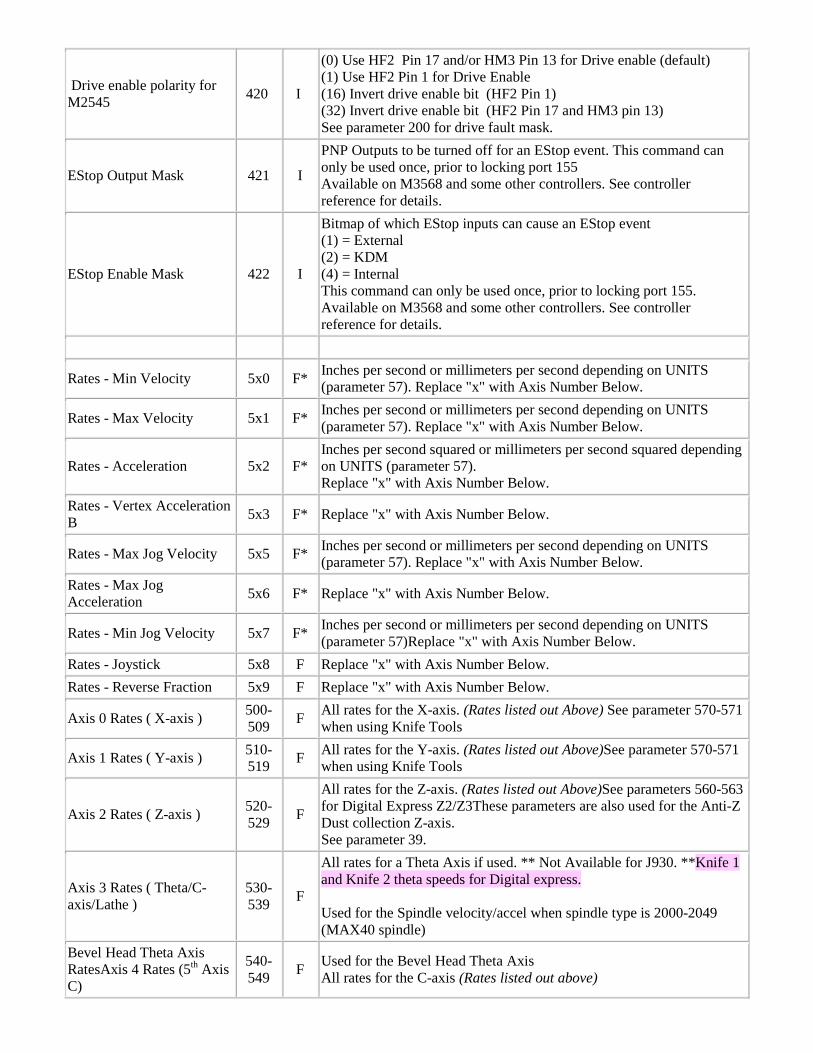
Drive enable polarity for M2545 420 I
(0) Use HF2 Pin 17 and/or HM3 Pin 13 for Drive enable (default) (1) Use HF2 Pin 1 for Drive Enable (16) Invert drive enable bit (HF2 Pin 1) (32) Invert drive enable bit (HF2 Pin 17 and HM3 pin 13) See parameter 200 for drive fault mask.
EStop Output Mask 421 I
PNP Outputs to be turned off for an EStop event. This command can only be used once, prior to locking port 155 Available on M3568 and some other controllers. See controller reference for details.
EStop Enable Mask 422 I
Bitmap of which EStop inputs can cause an EStop event (1) = External (2) = KDM (4) = Internal This command can only be used once, prior to locking port 155. Available on M3568 and some other controllers. See controller reference for details.
Rates - Min Velocity 5x0 F* Inches per second or millimeters per second depending on UNITS (parameter 57). Replace "x" with Axis Number Below.
Rates - Max Velocity 5x1 F* Inches per second or millimeters per second depending on UNITS (parameter 57). Replace "x" with Axis Number Below.
Rates - Acceleration 5x2 F* Inches per second squared or millimeters per second squared depending on UNITS (parameter 57). Replace "x" with Axis Number Below.
Rates - Vertex Acceleration B 5x3 F* Replace "x" with Axis Number Below.
Rates - Max Jog Velocity 5x5 F* Inches per second or millimeters per second depending on UNITS (parameter 57). Replace "x" with Axis Number Below.
Rates - Max Jog Acceleration 5x6 F* Replace "x" with Axis Number Below.
Rates - Min Jog Velocity 5x7 F* Inches per second or millimeters per second depending on UNITS (parameter 57)Replace "x" with Axis Number Below.
Rates - Joystick 5x8 F Replace "x" with Axis Number Below. Rates - Reverse Fraction 5x9 F Replace "x" with Axis Number Below.
Axis 0 Rates ( X-axis ) 500-509 F All rates for the X-axis. (Rates listed out Above) See parameter 570-571
when using Knife Tools
Axis 1 Rates ( Y-axis ) 510-519 F All rates for the Y-axis. (Rates listed out Above)See parameter 570-571
when using Knife Tools
Axis 2 Rates ( Z-axis ) 520-529 F
All rates for the Z-axis. (Rates listed out Above)See parameters 560-563 for Digital Express Z2/Z3These parameters are also used for the Anti-Z Dust collection Z-axis. See parameter 39.
Axis 3 Rates ( Theta/C-axis/Lathe )
530-539 F
All rates for a Theta Axis if used. ** Not Available for J930. **Knife 1 and Knife 2 theta speeds for Digital express. Used for the Spindle velocity/accel when spindle type is 2000-2049 (MAX40 spindle)
Bevel Head Theta Axis RatesAxis 4 Rates (5th Axis C)
540-549 F Used for the Bevel Head Theta Axis
All rates for the C-axis (Rates listed out above)
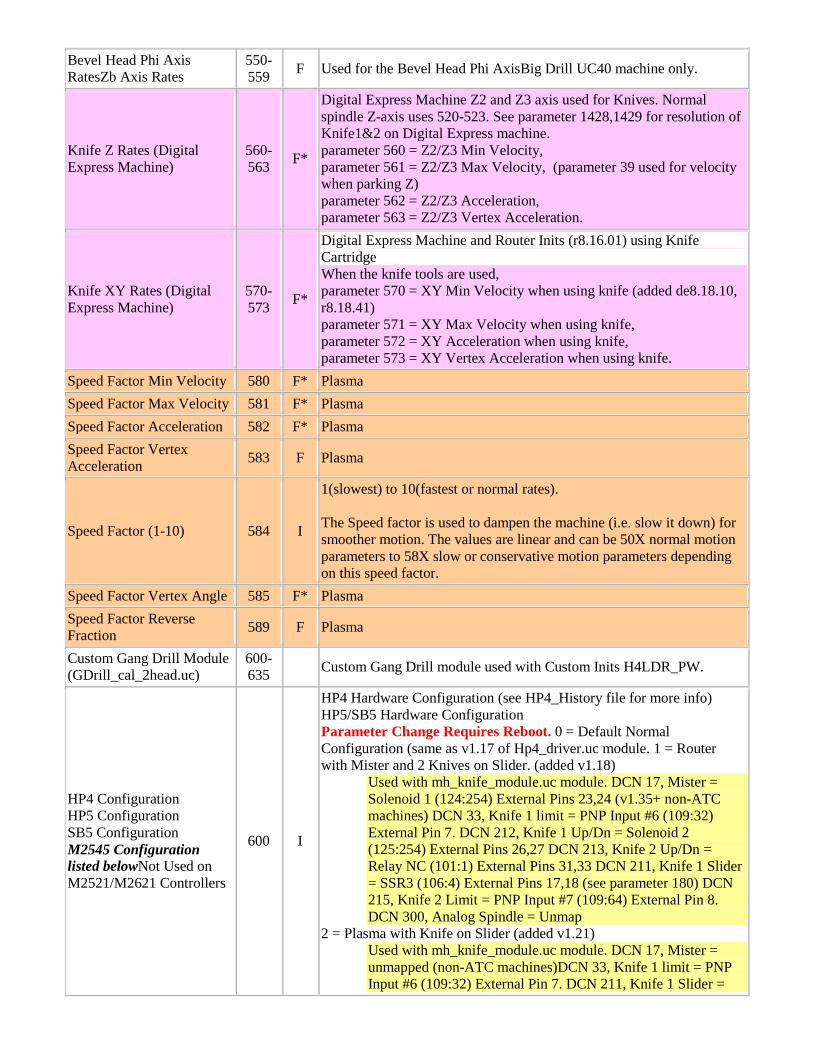
Bevel Head Phi Axis RatesZb Axis Rates
550-559 F Used for the Bevel Head Phi AxisBig Drill UC40 machine only.
Knife Z Rates (Digital Express Machine)
560-563 F*
Digital Express Machine Z2 and Z3 axis used for Knives. Normal spindle Z-axis uses 520-523. See parameter 1428,1429 for resolution of Knife1&2 on Digital Express machine. parameter 560 = Z2/Z3 Min Velocity, parameter 561 = Z2/Z3 Max Velocity, (parameter 39 used for velocity when parking Z) parameter 562 = Z2/Z3 Acceleration, parameter 563 = Z2/Z3 Vertex Acceleration.
Knife XY Rates (Digital Express Machine)
570-573 F*
Digital Express Machine and Router Inits (r8.16.01) using Knife Cartridge When the knife tools are used, parameter 570 = XY Min Velocity when using knife (added de8.18.10, r8.18.41) parameter 571 = XY Max Velocity when using knife, parameter 572 = XY Acceleration when using knife, parameter 573 = XY Vertex Acceleration when using knife.
Speed Factor Min Velocity 580 F* Plasma Speed Factor Max Velocity 581 F* Plasma Speed Factor Acceleration 582 F* Plasma Speed Factor Vertex Acceleration 583 F Plasma
Speed Factor (1-10) 584 I
1(slowest) to 10(fastest or normal rates). The Speed factor is used to dampen the machine (i.e. slow it down) for smoother motion. The values are linear and can be 50X normal motion parameters to 58X slow or conservative motion parameters depending on this speed factor.
Speed Factor Vertex Angle 585 F* Plasma Speed Factor Reverse Fraction 589 F Plasma
Custom Gang Drill Module (GDrill_cal_2head.uc)
600-635 Custom Gang Drill module used with Custom Inits H4LDR_PW.
HP4 Configuration HP5 Configuration SB5 Configuration M2545 Configuration listed belowNot Used on M2521/M2621 Controllers
600 I
HP4 Hardware Configuration (see HP4_History file for more info) HP5/SB5 Hardware Configuration Parameter Change Requires Reboot. 0 = Default Normal Configuration (same as v1.17 of Hp4_driver.uc module. 1 = Router with Mister and 2 Knives on Slider. (added v1.18)
Used with mh_knife_module.uc module. DCN 17, Mister = Solenoid 1 (124:254) External Pins 23,24 (v1.35+ non-ATC machines) DCN 33, Knife 1 limit = PNP Input #6 (109:32) External Pin 7. DCN 212, Knife 1 Up/Dn = Solenoid 2 (125:254) External Pins 26,27 DCN 213, Knife 2 Up/Dn = Relay NC (101:1) External Pins 31,33 DCN 211, Knife 1 Slider = SSR3 (106:4) External Pins 17,18 (see parameter 180) DCN 215, Knife 2 Limit = PNP Input #7 (109:64) External Pin 8. DCN 300, Analog Spindle = Unmap
2 = Plasma with Knife on Slider (added v1.21) Used with mh_knife_module.uc module. DCN 17, Mister = unmapped (non-ATC machines)DCN 33, Knife 1 limit = PNP Input #6 (109:32) External Pin 7. DCN 211, Knife 1 Slider =
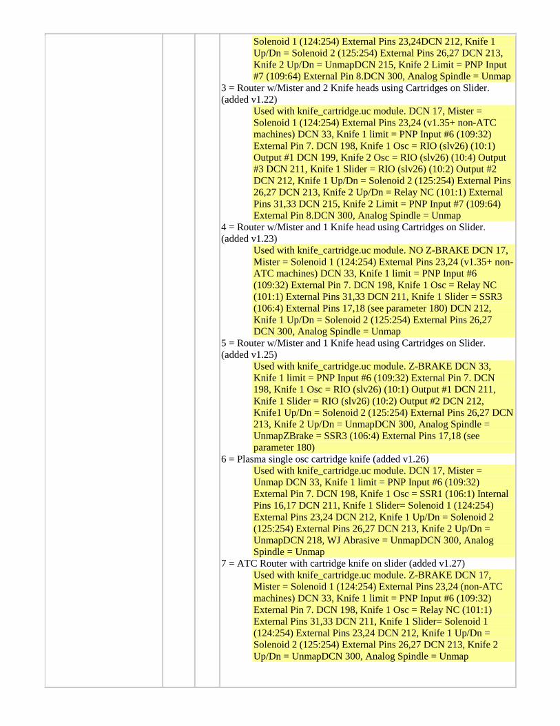
Solenoid 1 (124:254) External Pins 23,24DCN 212, Knife 1 Up/Dn = Solenoid 2 (125:254) External Pins 26,27 DCN 213, Knife 2 Up/Dn = UnmapDCN 215, Knife 2 Limit = PNP Input #7 (109:64) External Pin 8.DCN 300, Analog Spindle = Unmap
3 = Router w/Mister and 2 Knife heads using Cartridges on Slider. (added v1.22)
Used with knife_cartridge.uc module. DCN 17, Mister = Solenoid 1 (124:254) External Pins 23,24 (v1.35+ non-ATC machines) DCN 33, Knife 1 limit = PNP Input #6 (109:32) External Pin 7. DCN 198, Knife 1 Osc = RIO (slv26) (10:1) Output #1 DCN 199, Knife 2 Osc = RIO (slv26) (10:4) Output #3 DCN 211, Knife 1 Slider = RIO (slv26) (10:2) Output #2 DCN 212, Knife 1 Up/Dn = Solenoid 2 (125:254) External Pins 26,27 DCN 213, Knife 2 Up/Dn = Relay NC (101:1) External Pins 31,33 DCN 215, Knife 2 Limit = PNP Input #7 (109:64) External Pin 8.DCN 300, Analog Spindle = Unmap
4 = Router w/Mister and 1 Knife head using Cartridges on Slider. (added v1.23)
Used with knife_cartridge.uc module. NO Z-BRAKE DCN 17, Mister = Solenoid 1 (124:254) External Pins 23,24 (v1.35+ non-ATC machines) DCN 33, Knife 1 limit = PNP Input #6 (109:32) External Pin 7. DCN 198, Knife 1 Osc = Relay NC (101:1) External Pins 31,33 DCN 211, Knife 1 Slider = SSR3 (106:4) External Pins 17,18 (see parameter 180) DCN 212, Knife 1 Up/Dn = Solenoid 2 (125:254) External Pins 26,27 DCN 300, Analog Spindle = Unmap
5 = Router w/Mister and 1 Knife head using Cartridges on Slider. (added v1.25)
Used with knife_cartridge.uc module. Z-BRAKE DCN 33, Knife 1 limit = PNP Input #6 (109:32) External Pin 7. DCN 198, Knife 1 Osc = RIO (slv26) (10:1) Output #1 DCN 211, Knife 1 Slider = RIO (slv26) (10:2) Output #2 DCN 212, Knife1 Up/Dn = Solenoid 2 (125:254) External Pins 26,27 DCN 213, Knife 2 Up/Dn = UnmapDCN 300, Analog Spindle = UnmapZBrake = SSR3 (106:4) External Pins 17,18 (see parameter 180)
6 = Plasma single osc cartridge knife (added v1.26) Used with knife_cartridge.uc module. DCN 17, Mister = Unmap DCN 33, Knife 1 limit = PNP Input #6 (109:32) External Pin 7. DCN 198, Knife 1 Osc = SSR1 (106:1) Internal Pins 16,17 DCN 211, Knife 1 Slider= Solenoid 1 (124:254) External Pins 23,24 DCN 212, Knife 1 Up/Dn = Solenoid 2 (125:254) External Pins 26,27 DCN 213, Knife 2 Up/Dn = UnmapDCN 218, WJ Abrasive = UnmapDCN 300, Analog Spindle = Unmap
7 = ATC Router with cartridge knife on slider (added v1.27) Used with knife_cartridge.uc module. Z-BRAKE DCN 17, Mister = Solenoid 1 (124:254) External Pins 23,24 (non-ATC machines) DCN 33, Knife 1 limit = PNP Input #6 (109:32) External Pin 7. DCN 198, Knife 1 Osc = Relay NC (101:1) External Pins 31,33 DCN 211, Knife 1 Slider= Solenoid 1 (124:254) External Pins 23,24 DCN 212, Knife 1 Up/Dn = Solenoid 2 (125:254) External Pins 26,27 DCN 213, Knife 2 Up/Dn = UnmapDCN 300, Analog Spindle = Unmap
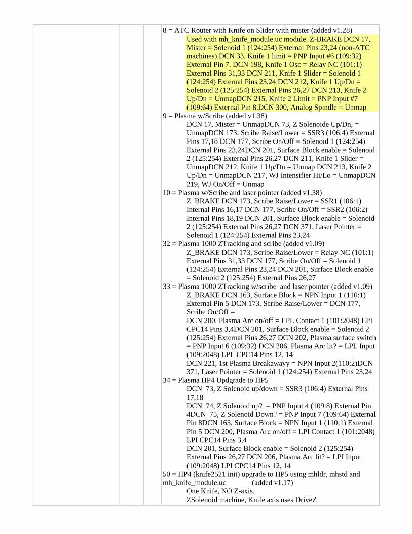
8 = ATC Router with Knife on Slider with mister (added v1.28) Used with mh_knife_module.uc module. Z-BRAKE DCN 17, Mister = Solenoid 1 (124:254) External Pins 23,24 (non-ATC machines) DCN 33, Knife 1 limit = PNP Input #6 (109:32) External Pin 7. DCN 198, Knife 1 Osc = Relay NC (101:1) External Pins 31,33 DCN 211, Knife 1 Slider = Solenoid 1 (124:254) External Pins 23,24 DCN 212, Knife 1 Up/Dn = Solenoid 2 (125:254) External Pins 26,27 DCN 213, Knife 2 Up/Dn = UnmapDCN 215, Knife 2 Limit = PNP Input #7 (109:64) External Pin 8.DCN 300, Analog Spindle = Unmap
9 = Plasma w/Scribe (added v1.38) DCN 17, Mister = UnmapDCN 73, Z Solenoide Up/Dn, = UnmapDCN 173, Scribe Raise/Lower = SSR3 (106:4) External Pins 17,18 DCN 177, Scribe On/Off = Solenoid 1 (124:254) External Pins 23,24DCN 201, Surface Block enable = Solenoid 2 (125:254) External Pins 26,27 DCN 211, Knife 1 Slider = UnmapDCN 212, Knife 1 Up/Dn = Unmap DCN 213, Knife 2 Up/Dn = UnmapDCN 217, WJ Intensifier Hi/Lo = UnmapDCN 219, WJ On/Off = Unmap
10 = Plasma w/Scribe and laser pointer (added v1.38) Z_BRAKE DCN 173, Scribe Raise/Lower = SSR1 (106:1) Internal Pins 16,17 DCN 177, Scribe On/Off = SSR2 (106:2) Internal Pins 18,19 DCN 201, Surface Block enable = Solenoid 2 (125:254) External Pins 26,27 DCN 371, Laser Pointer = Solenoid 1 (124:254) External Pins 23,24
32 = Plasma 1000 ZTracking and scribe (added v1.09) Z_BRAKE DCN 173, Scribe Raise/Lower = Relay NC (101:1) External Pins 31,33 DCN 177, Scribe On/Off = Solenoid 1 (124:254) External Pins 23,24 DCN 201, Surface Block enable = Solenoid 2 (125:254) External Pins 26,27
33 = Plasma 1000 ZTracking w/scribe and laser pointer (added v1.09) Z_BRAKE DCN 163, Surface Block = NPN Input 1 (110:1) External Pin 5 DCN 173, Scribe Raise/Lower = DCN 177, Scribe On/Off = DCN 200, Plasma Arc on/off = LPL Contact 1 (101:2048) LPI CPC14 Pins 3,4DCN 201, Surface Block enable = Solenoid 2 (125:254) External Pins 26,27 DCN 202, Plasma surface switch = PNP Input 6 (109:32) DCN 206, Plasma Arc lit? = LPL Input (109:2048) LPL CPC14 Pins 12, 14 DCN 221, 1st Plasma Breakawayy = NPN Input 2(110:2)DCN 371, Laser Pointer = Solenoid 1 (124:254) External Pins 23,24
34 = Plasma HP4 Updgrade to HP5 DCN 73, Z Solenoid up/down = SSR3 (106:4) External Pins 17,18 DCN 74, Z Solenoid up? = PNP Input 4 (109:8) External Pin 4DCN 75, Z Solenoid Down? = PNP Input 7 (109:64) External Pin 8DCN 163, Surface Block = NPN Input 1 (110:1) External Pin 5 DCN 200, Plasma Arc on/off = LPI Contact 1 (101:2048) LPI CPC14 Pins 3,4 DCN 201, Surface Block enable = Solenoid 2 (125:254) External Pins 26,27 DCN 206, Plasma Arc lit? = LPI Input (109:2048) LPI CPC14 Pins 12, 14
50 = HP4 (knife2521 init) upgrade to HP5 using mhldr, mhstd and mh_knife_module.uc (added v1.17)
One Knife, NO Z-axis. ZSolenoid machine, Knife axis uses DriveZ
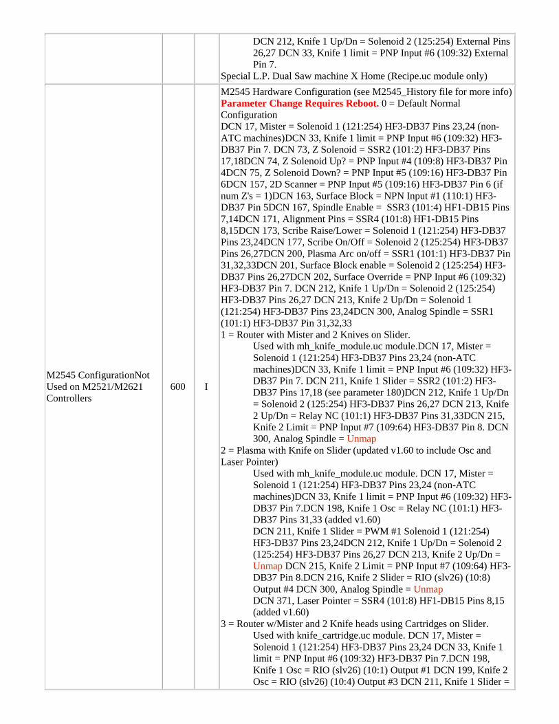
DCN 212, Knife 1 Up/Dn = Solenoid 2 (125:254) External Pins 26,27 DCN 33, Knife 1 limit = PNP Input #6 (109:32) External Pin 7.
Special L.P. Dual Saw machine X Home (Recipe.uc module only)
M2545 ConfigurationNot Used on M2521/M2621 Controllers
600 I
M2545 Hardware Configuration (see M2545_History file for more info) Parameter Change Requires Reboot. 0 = Default Normal Configuration DCN 17, Mister = Solenoid 1 (121:254) HF3-DB37 Pins 23,24 (non-ATC machines)DCN 33, Knife 1 limit = PNP Input #6 (109:32) HF3-DB37 Pin 7. DCN 73, Z Solenoid = SSR2 (101:2) HF3-DB37 Pins 17,18DCN 74, Z Solenoid Up? = PNP Input #4 (109:8) HF3-DB37 Pin 4DCN 75, Z Solenoid Down? = PNP Input #5 (109:16) HF3-DB37 Pin 6DCN 157, 2D Scanner = PNP Input #5 (109:16) HF3-DB37 Pin 6 (if num Z's = 1)DCN 163, Surface Block = NPN Input #1 (110:1) HF3-DB37 Pin 5DCN 167, Spindle Enable = SSR3 (101:4) HF1-DB15 Pins 7,14DCN 171, Alignment Pins = SSR4 (101:8) HF1-DB15 Pins 8,15DCN 173, Scribe Raise/Lower = Solenoid 1 (121:254) HF3-DB37 Pins 23,24DCN 177, Scribe On/Off = Solenoid 2 (125:254) HF3-DB37 Pins 26,27DCN 200, Plasma Arc on/off = SSR1 (101:1) HF3-DB37 Pin 31,32,33DCN 201, Surface Block enable = Solenoid 2 (125:254) HF3-DB37 Pins 26,27DCN 202, Surface Override = PNP Input #6 (109:32) HF3-DB37 Pin 7. DCN 212, Knife 1 Up/Dn = Solenoid 2 (125:254) HF3-DB37 Pins 26,27 DCN 213, Knife 2 Up/Dn = Solenoid 1 (121:254) HF3-DB37 Pins 23,24DCN 300, Analog Spindle = SSR1 (101:1) HF3-DB37 Pin 31,32,33 1 = Router with Mister and 2 Knives on Slider.
Used with mh_knife_module.uc module.DCN 17, Mister = Solenoid 1 (121:254) HF3-DB37 Pins 23,24 (non-ATC machines)DCN 33, Knife 1 limit = PNP Input #6 (109:32) HF3-DB37 Pin 7. DCN 211, Knife 1 Slider = SSR2 (101:2) HF3-DB37 Pins 17,18 (see parameter 180)DCN 212, Knife 1 Up/Dn = Solenoid 2 (125:254) HF3-DB37 Pins 26,27 DCN 213, Knife 2 Up/Dn = Relay NC (101:1) HF3-DB37 Pins 31,33DCN 215, Knife 2 Limit = PNP Input #7 (109:64) HF3-DB37 Pin 8. DCN 300, Analog Spindle = Unmap
2 = Plasma with Knife on Slider (updated v1.60 to include Osc and Laser Pointer)
Used with mh_knife_module.uc module. DCN 17, Mister = Solenoid 1 (121:254) HF3-DB37 Pins 23,24 (non-ATC machines)DCN 33, Knife 1 limit = PNP Input #6 (109:32) HF3-DB37 Pin 7.DCN 198, Knife 1 Osc = Relay NC (101:1) HF3-DB37 Pins 31,33 (added v1.60) DCN 211, Knife 1 Slider = PWM #1 Solenoid 1 (121:254) HF3-DB37 Pins 23,24DCN 212, Knife 1 Up/Dn = Solenoid 2 (125:254) HF3-DB37 Pins 26,27 DCN 213, Knife 2 Up/Dn = Unmap DCN 215, Knife 2 Limit = PNP Input #7 (109:64) HF3-DB37 Pin 8.DCN 216, Knife 2 Slider = RIO (slv26) (10:8) Output #4 DCN 300, Analog Spindle = Unmap DCN 371, Laser Pointer = SSR4 (101:8) HF1-DB15 Pins 8,15 (added v1.60)
3 = Router w/Mister and 2 Knife heads using Cartridges on Slider. Used with knife_cartridge.uc module. DCN 17, Mister = Solenoid 1 (121:254) HF3-DB37 Pins 23,24 DCN 33, Knife 1 limit = PNP Input #6 (109:32) HF3-DB37 Pin 7.DCN 198, Knife 1 Osc = RIO (slv26) (10:1) Output #1 DCN 199, Knife 2 Osc = RIO (slv26) (10:4) Output #3 DCN 211, Knife 1 Slider =
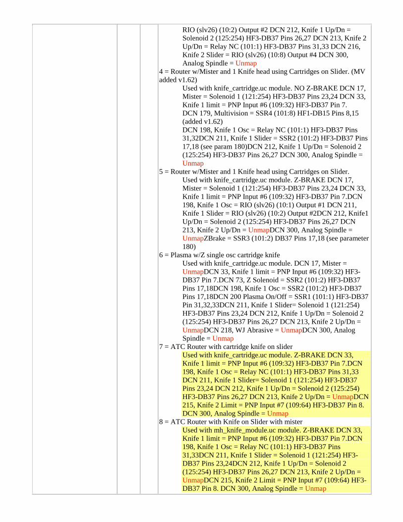
RIO (slv26) (10:2) Output #2 DCN 212, Knife 1 Up/Dn = Solenoid 2 (125:254) HF3-DB37 Pins 26,27 DCN 213, Knife 2 Up/Dn = Relay NC (101:1) HF3-DB37 Pins 31,33 DCN 216, Knife 2 Slider = RIO (slv26) (10:8) Output #4 DCN 300, Analog Spindle = Unmap
4 = Router w/Mister and 1 Knife head using Cartridges on Slider. (MV added v1.62)
Used with knife_cartridge.uc module. NO Z-BRAKE DCN 17, Mister = Solenoid 1 (121:254) HF3-DB37 Pins 23,24 DCN 33, Knife 1 limit = PNP Input #6 (109:32) HF3-DB37 Pin 7. DCN 179, Multivision = SSR4 (101:8) HF1-DB15 Pins 8,15 (added v1.62) DCN 198, Knife 1 Osc = Relay NC (101:1) HF3-DB37 Pins 31,32DCN 211, Knife 1 Slider = SSR2 (101:2) HF3-DB37 Pins 17,18 (see param 180)DCN 212, Knife 1 Up/Dn = Solenoid 2 (125:254) HF3-DB37 Pins 26,27 DCN 300, Analog Spindle = Unmap
5 = Router w/Mister and 1 Knife head using Cartridges on Slider. Used with knife_cartridge.uc module. Z-BRAKE DCN 17, Mister = Solenoid 1 (121:254) HF3-DB37 Pins 23,24 DCN 33, Knife 1 limit = PNP Input #6 (109:32) HF3-DB37 Pin 7.DCN 198, Knife 1 Osc = RIO (slv26) (10:1) Output #1 DCN 211, Knife 1 Slider = RIO (slv26) (10:2) Output #2DCN 212, Knife1 Up/Dn = Solenoid 2 (125:254) HF3-DB37 Pins 26,27 DCN 213, Knife 2 Up/Dn = UnmapDCN 300, Analog Spindle = UnmapZBrake = SSR3 (101:2) DB37 Pins 17,18 (see parameter 180)
6 = Plasma w/Z single osc cartridge knife Used with knife_cartridge.uc module. DCN 17, Mister = UnmapDCN 33, Knife 1 limit = PNP Input #6 (109:32) HF3-DB37 Pin 7.DCN 73, Z Solenoid = SSR2 (101:2) HF3-DB37 Pins 17,18DCN 198, Knife 1 Osc = SSR2 (101:2) HF3-DB37 Pins 17,18DCN 200 Plasma On/Off = SSR1 (101:1) HF3-DB37 Pin 31,32,33DCN 211, Knife 1 Slider= Solenoid 1 (121:254) HF3-DB37 Pins 23,24 DCN 212, Knife 1 Up/Dn = Solenoid 2 (125:254) HF3-DB37 Pins 26,27 DCN 213, Knife 2 Up/Dn = UnmapDCN 218, WJ Abrasive = UnmapDCN 300, Analog Spindle = Unmap
7 = ATC Router with cartridge knife on slider Used with knife_cartridge.uc module. Z-BRAKE DCN 33, Knife 1 limit = PNP Input #6 (109:32) HF3-DB37 Pin 7.DCN 198, Knife 1 Osc = Relay NC (101:1) HF3-DB37 Pins 31,33 DCN 211, Knife 1 Slider= Solenoid 1 (121:254) HF3-DB37 Pins 23,24 DCN 212, Knife 1 Up/Dn = Solenoid 2 (125:254) HF3-DB37 Pins 26,27 DCN 213, Knife 2 Up/Dn = UnmapDCN 215, Knife 2 Limit = PNP Input #7 (109:64) HF3-DB37 Pin 8. DCN 300, Analog Spindle = Unmap
8 = ATC Router with Knife on Slider with mister Used with mh_knife_module.uc module. Z-BRAKE DCN 33, Knife 1 limit = PNP Input #6 (109:32) HF3-DB37 Pin 7.DCN 198, Knife 1 Osc = Relay NC (101:1) HF3-DB37 Pins 31,33DCN 211, Knife 1 Slider = Solenoid 1 (121:254) HF3-DB37 Pins 23,24DCN 212, Knife 1 Up/Dn = Solenoid 2 (125:254) HF3-DB37 Pins 26,27 DCN 213, Knife 2 Up/Dn = UnmapDCN 215, Knife 2 Limit = PNP Input #7 (109:64) HF3-DB37 Pin 8. DCN 300, Analog Spindle = Unmap
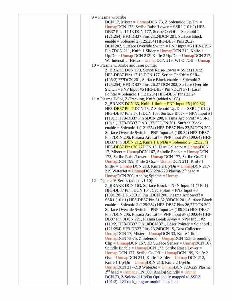
9 = Plasma w/Scribe DCN 17, Mister = UnmapDCN 73, Z Solenoide Up/Dn, = UnmapDCN 173, Scribe Raise/Lower = SSR2 (101:2) HF3-DB37 Pins 17,18 DCN 177, Scribe On/Off = Solenoid 1 (121:254) HF3-DB37 Pins 23,24DCN 201, Surface Block enable = Solenoid 2 (125:254) HF3-DB37 Pins 26,27 DCN 202, Surface Override Switch = PNP Input #6 HF3-DB37 Pin 7DCN 211, Knife 1 Slider = UnmapDCN 212, Knife 1 Up/Dn = Unmap DCN 213, Knife 2 Up/Dn = UnmapDCN 217, WJ Intensifier Hi/Lo = UnmapDCN 219, WJ On/Off = Unmap
10 = Plasma w/Scribe and laser pointer Z_BRAKE DCN 173, Scribe Raise/Lower = SSR3 (101:2) HF3-DB37 Pins 17,18 DCN 177, Scribe On/Off = SSR4 (106:2) ???DCN 201, Surface Block enable = Solenoid 2 (125:254) HF3-DB37 Pins 26,27 DCN 202, Surface Override Switch = PNP Input #6 HF3-DB37 Pin 7DCN 371, Laser Pointer = Solenoid 1 (121:254) HF3-DB37 Pins 23,24
11 = Plasma Z-Sol, Z-Tracking, Knife (added v1.08) Z_BRAKE DCN 33, Knife 1 limit = PNP Input #6 (109:32) HF3-DB37 Pin 7.DCN 73, Z Solenoid Up/Dn, = SSR2 (101:2) HF3-DB37 Pins 17,18DCN 163, Surface Block = NPN Input #1 (110:1) HF3-DB37 Pin 5DCN 200, Plasma Arc on/off = SSR1 (101:1) HF3-DB37 Pin 31,32,33DCN 201, Surface Block enable = Solenoid 1 (121:254) HF3-DB37 Pins 23,24DCN 202, Surface Override Switch = PNP Input #6 (109:32) HF3-DB37 Pin 7DCN 206, Plasma Arc Lit? = PNP Input #7 (109:64) HF3-DB37 Pin 8DCN 212, Knife 1 Up/Dn = Solenoid 2 (125:254) HF3-DB37 Pins 26,27DCN 15, Dust Collector = UnmapDCN 17, Mister = UnmapDCN 167, Spindle Enable = UnmapDCN 173, Scribe Raise/Lower = Unmap DCN 177, Scribe On/Off = UnmapDCN 199, Knife 2 Osc = UnmapDCN 211, Knife 1 Slider = Unmap DCN 213, Knife 2 Up/Dn = UnmapDCN 217-219 WaterJet = UnmapDCN 220-229 Plasma 2nd head = UnmapDCN 300, Analog Spindle = Unmap
12 = Plasma V-Series (added v1.10) Z_BRAKE DCN 163, Surface Block = NPN Input #1 (110:1) HF3-DB37 Pin 5DCN 164, Cycle Start = PNP Input #8 (109:128) HF1-DB15 Pin 1DCN 200, Plasma Arc on/off = SSR1 (101:1) HF3-DB37 Pin 31,32,33DCN 201, Surface Block enable = Solenoid 2 (125:254) HF3-DB37 Pins 26,27DCN 202, Surface Override Switch = PNP Input #6 (109:32) HF3-DB37 Pin 7DCN 206, Plasma Arc Lit? = PNP Input #7 (109:64) HF3-DB37 Pin 8DCN 221, Plasma Break Away = NPN Input #2 (110:2) HF3-DB37 Pin 10DCN 371, Laser Pointer = Solenoid 1 (121:254) HF3-DB37 Pins 23,24DCN 15, Dust Collector = UnmapDCN 17, Mister = UnmapDCN 33, Knife 1 limit = UnmapDCN 73-75, Z Solenoid = UnmapDCN 153, Grounding Clip = UnmapDCN 157, 3D Surface Sensor = UnmapDCN 167, Spindle Enable = UnmapDCN 173, Scribe Raise/Lower = Unmap DCN 177, Scribe On/Off = UnmapDCN 199, Knife 2 Osc = UnmapDCN 211, Knife 1 Slider = Unmap DCN 212, Knife 1 Up/Dn = UnmapDCN 213, Knife 2 Up/Dn = UnmapDCN 217-219 WaterJet = UnmapDCN 220-229 Plasma 2nd head = UnmapDCN 300, Analog Spindle = Unmap DCN 73, Z Solenoid Up/Dn Optionally mapped to SSR2 (101:2) if ZTrack_drag.uc module installed.
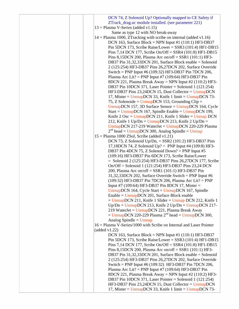
DCN 74, Z Solenoid Up? Optionally mapped to CE Safety if ZTrack_drag.uc module installed. (see parameter 221)
13 = Plasma V-Series (added v1.15) Same as type 12 with NO break-away 14 = Plasma 1000, ZTracking with scribe on internal (added v1.16)
DCN 163, Surface Block = NPN Input #1 (110:1) HF3-DB37 Pin 5DCN 173, Scribe Raise/Lower = SSR3 (101:4) HF1-DB15 Pins 7,14 DCN 177, Scribe On/Off = SSR4 (101:8) HF1-DB15 Pins 8,15DCN 200, Plasma Arc on/off = SSR1 (101:1) HF3-DB37 Pin 31,32,33DCN 201, Surface Block enable = Solenoid 2 (125:254) HF3-DB37 Pins 26,27DCN 202, Surface Override Switch = PNP Input #6 (109:32) HF3-DB37 Pin 7DCN 206, Plasma Arc Lit? = PNP Input #7 (109:64) HF3-DB37 Pin 8DCN 221, Plasma Break Away = NPN Input #2 (110:2) HF3-DB37 Pin 10DCN 371, Laser Pointer = Solenoid 1 (121:254) HF3-DB37 Pins 23,24DCN 15, Dust Collector = UnmapDCN 17, Mister = UnmapDCN 33, Knife 1 limit = UnmapDCN 73-75, Z Solenoide = UnmapDCN 153, Grounding Clip = UnmapDCN 157, 3D Surface Sensor = UnmapDCN 164, Cycle Start = UnmapDCN 167, Spindle Enable = UnmapDCN 199, Knife 2 Osc = UnmapDCN 211, Knife 1 Slider = Unmap DCN 212, Knife 1 Up/Dn = UnmapDCN 213, Knife 2 Up/Dn = UnmapDCN 217-219 WaterJet = UnmapDCN 220-229 Plasma 2nd head = UnmapDCN 300, Analog Spindle = Unmap
15 = Plasma 1000 ZSol, Scribe (added v1.21) DCN 73, Z Solenoid Up/Dn, = SSR2 (101:2) HF3-DB37 Pins 17,18DCN 74, Z Solenoid Up? = PNP Input #4 (109:8) HF3-DB37 Pin 4DCN 75, Z Solenoid Down? = PNP Input #5 (109:16) HF3-DB37 Pin 6DCN 173, Scribe Raise/Lower = Solenoid 2 (125:254) HF3-DB37 Pins 26,27DCN 177, Scribe On/Off = Solenoid 1 (121:254) HF3-DB37 Pins 23,24 DCN 200, Plasma Arc on/off = SSR1 (101:1) HF3-DB37 Pin 31,32,33DCN 202, Surface Override Switch = PNP Input #6 (109:32) HF3-DB37 Pin 7DCN 206, Plasma Arc Lit? = PNP Input #7 (109:64) HF3-DB37 Pin 8DCN 17, Mister = UnmapDCN 164, Cycle Start = UnmapDCN 167, Spindle Enable = UnmapDCN 201, Surface Block enable = UnmapDCN 211, Knife 1 Slider = Unmap DCN 212, Knife 1 Up/Dn = UnmapDCN 213, Knife 2 Up/Dn = UnmapDCN 217-219 WaterJet = UnmapDCN 221, Plasma Break Away = UnmapDCN 220-229 Plasma 2nd head = UnmapDCN 300, Analog Spindle = Unmap
16 = Plasma V-Series/1000 with Scribe on Internal and Laser Pointer (added v1.22)
DCN 163, Surface Block = NPN Input #1 (110:1) HF3-DB37 Pin 5DCN 173, Scribe Raise/Lower = SSR3 (101:4) HF1-DB15 Pins 7,14 DCN 177, Scribe On/Off = SSR4 (101:8) HF1-DB15 Pins 8,15DCN 200, Plasma Arc on/off = SSR1 (101:1) HF3-DB37 Pin 31,32,33DCN 201, Surface Block enable = Solenoid 2 (125:254) HF3-DB37 Pins 26,27DCN 202, Surface Override Switch = PNP Input #6 (109:32) HF3-DB37 Pin 7DCN 206, Plasma Arc Lit? = PNP Input #7 (109:64) HF3-DB37 Pin 8DCN 221, Plasma Break Away = NPN Input #2 (110:2) HF3-DB37 Pin 10DCN 371, Laser Pointer = Solenoid 1 (121:254) HF3-DB37 Pins 23,24DCN 15, Dust Collector = UnmapDCN 17, Mister = UnmapDCN 33, Knife 1 limit = UnmapDCN 73-
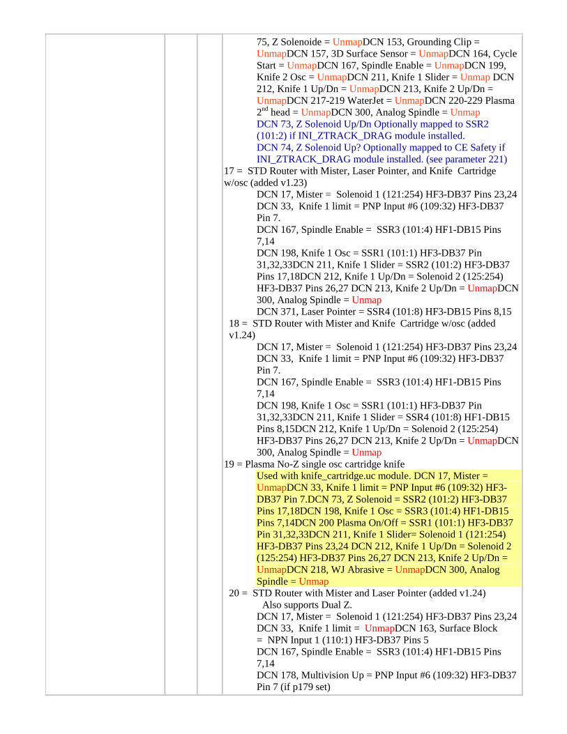
75, Z Solenoide = UnmapDCN 153, Grounding Clip = UnmapDCN 157, 3D Surface Sensor = UnmapDCN 164, Cycle Start = UnmapDCN 167, Spindle Enable = UnmapDCN 199, Knife 2 Osc = UnmapDCN 211, Knife 1 Slider = Unmap DCN 212, Knife 1 Up/Dn = UnmapDCN 213, Knife 2 Up/Dn = UnmapDCN 217-219 WaterJet = UnmapDCN 220-229 Plasma 2nd head = UnmapDCN 300, Analog Spindle = Unmap DCN 73, Z Solenoid Up/Dn Optionally mapped to SSR2 (101:2) if INI_ZTRACK_DRAG module installed. DCN 74, Z Solenoid Up? Optionally mapped to CE Safety if INI_ZTRACK_DRAG module installed. (see parameter 221)
17 = STD Router with Mister, Laser Pointer, and Knife Cartridge w/osc (added v1.23)
DCN 17, Mister = Solenoid 1 (121:254) HF3-DB37 Pins 23,24 DCN 33, Knife 1 limit = PNP Input #6 (109:32) HF3-DB37 Pin 7. DCN 167, Spindle Enable = SSR3 (101:4) HF1-DB15 Pins 7,14 DCN 198, Knife 1 Osc = SSR1 (101:1) HF3-DB37 Pin 31,32,33DCN 211, Knife 1 Slider = SSR2 (101:2) HF3-DB37 Pins 17,18DCN 212, Knife 1 Up/Dn = Solenoid 2 (125:254) HF3-DB37 Pins 26,27 DCN 213, Knife 2 Up/Dn = UnmapDCN 300, Analog Spindle = Unmap DCN 371, Laser Pointer = SSR4 (101:8) HF3-DB15 Pins 8,15
18 = STD Router with Mister and Knife Cartridge w/osc (added v1.24)
DCN 17, Mister = Solenoid 1 (121:254) HF3-DB37 Pins 23,24 DCN 33, Knife 1 limit = PNP Input #6 (109:32) HF3-DB37 Pin 7. DCN 167, Spindle Enable = SSR3 (101:4) HF1-DB15 Pins 7,14 DCN 198, Knife 1 Osc = SSR1 (101:1) HF3-DB37 Pin 31,32,33DCN 211, Knife 1 Slider = SSR4 (101:8) HF1-DB15 Pins 8,15DCN 212, Knife 1 Up/Dn = Solenoid 2 (125:254) HF3-DB37 Pins 26,27 DCN 213, Knife 2 Up/Dn = UnmapDCN 300, Analog Spindle = Unmap
19 = Plasma No-Z single osc cartridge knife Used with knife_cartridge.uc module. DCN 17, Mister = UnmapDCN 33, Knife 1 limit = PNP Input #6 (109:32) HF3-DB37 Pin 7.DCN 73, Z Solenoid = SSR2 (101:2) HF3-DB37 Pins 17,18DCN 198, Knife 1 Osc = SSR3 (101:4) HF1-DB15 Pins 7,14DCN 200 Plasma On/Off = SSR1 (101:1) HF3-DB37 Pin 31,32,33DCN 211, Knife 1 Slider= Solenoid 1 (121:254) HF3-DB37 Pins 23,24 DCN 212, Knife 1 Up/Dn = Solenoid 2 (125:254) HF3-DB37 Pins 26,27 DCN 213, Knife 2 Up/Dn = UnmapDCN 218, WJ Abrasive = UnmapDCN 300, Analog Spindle = Unmap
20 = STD Router with Mister and Laser Pointer (added v1.24) Also supports Dual Z.
DCN 17, Mister = Solenoid 1 (121:254) HF3-DB37 Pins 23,24 DCN 33, Knife 1 limit = UnmapDCN 163, Surface Block = NPN Input 1 (110:1) HF3-DB37 Pins 5 DCN 167, Spindle Enable = SSR3 (101:4) HF1-DB15 Pins 7,14 DCN 178, Multivision Up = PNP Input #6 (109:32) HF3-DB37 Pin 7 (if p179 set)
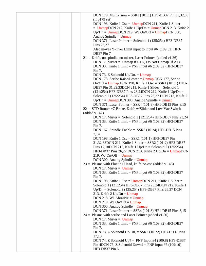
DCN 179, Multivision = SSR1 (101:1) HF3-DB37 Pin 31,32,33 (if p179 set) DCN 198, Knife 1 Osc = UnmapDCN 211, Knife 1 Slider = UnmapDCN 212, Knife 1 Up/Dn = UnmapDCN 213, Knife 2 Up/Dn = UnmapDCN 219, WJ On/Off = UnmapDCN 300, Analog Spindle = Unmap DCN 371, Laser Pointer = Solenoid 1 (125:254) HF3-DB37 Pins 26,27 Also moves Y-Over Limit input to input #6 (109:32) HF3-DB37 Pin 7
21 = Knife, no spindle, no mister, Laser Pointer (added v1.36) DCN 17, Mister = Unmap if STD, Do Not Unmap if ATC DCN 33, Knife 1 limit = PNP Input #6 (109:32) HF3-DB37 Pin 7. DCN 73, Z Solenoid Up/Dn, = Unmap DCN 173, Scribe Raise/Lower = Unmap DCN 177, Scribe On/Off = Unmap DCN 198, Knife 1 Osc = SSR1 (101:1) HF3-DB37 Pin 31,32,33DCN 211, Knife 1 Slider = Solenoid 1 (121:254) HF3-DB37 Pins 23,24DCN 212, Knife 1 Up/Dn = Solenoid 2 (125:254) HF3-DB37 Pins 26,27 DCN 213, Knife 2 Up/Dn = UnmapDCN 300, Analog Spindle = Unmap DCN 371, Laser Pointer = SSR4 (101:8) HF1-DB15 Pins 8,15
22 = STD Router +Z Brake, Knife w/Slider and Low Vac Switch (added v1.42)
DCN 17, Mister = Solenoid 1 (121:254) HF3-DB37 Pins 23,24 DCN 33, Knife 1 limit = PNP Input #6 (109:32) HF3-DB37 Pin 7. DCN 167, Spindle Enable = SSR3 (101:4) HF1-DB15 Pins 7,14 DCN 198, Knife 1 Osc = SSR1 (101:1) HF3-DB37 Pin 31,32,33DCN 211, Knife 1 Slider = SSR2 (101:2) HF3-DB37 Pins 17,18DCN 212, Knife 1 Up/Dn = Solenoid 2 (125:254) HF3-DB37 Pins 26,27 DCN 213, Knife 2 Up/Dn = UnmapDCN 219, WJ On/Off = Unmap DCN 300, Analog Spindle = Unmap
23 = Plasma with Floating Head, knife no-osc (added v1.48) DCN 17, Mister = Unmap DCN 33, Knife 1 limit = PNP Input #6 (109:32) HF3-DB37 Pin 7. DCN 198, Knife 1 Osc = UnmapDCN 211, Knife 1 Slider = Solenoid 1 (121:254) HF3-DB37 Pins 23,24DCN 212, Knife 1 Up/Dn = Solenoid 2 (125:254) HF3-DB37 Pins 26,27 DCN 213, Knife 2 Up/Dn = Unmap DCN 218, WJ Abrasive = Unmap DCN 219, WJ On/Off = Unmap DCN 300, Analog Spindle = Unmap DCN 371, Laser Pointer = SSR4 (101:8) HF1-DB15 Pins 8,15
24 = Plasma with scribe and Laser Pointer (added v1.50) DCN 17, Mister = Unmap DCN 33, Knife 1 limit = PNP Input #6 (109:32) HF3-DB37 Pin 7. DCN 73, Z Solenoid Up/Dn, = SSR2 (101:2) HF3-DB37 Pins 17,18 DCN 74, Z Solenoid Up? = PNP Input #4 (109:8) HF3-DB37 Pin 4DCN 75, Z Solenoid Down? = PNP Input #5 (109:16) HF3-DB37 Pin 6
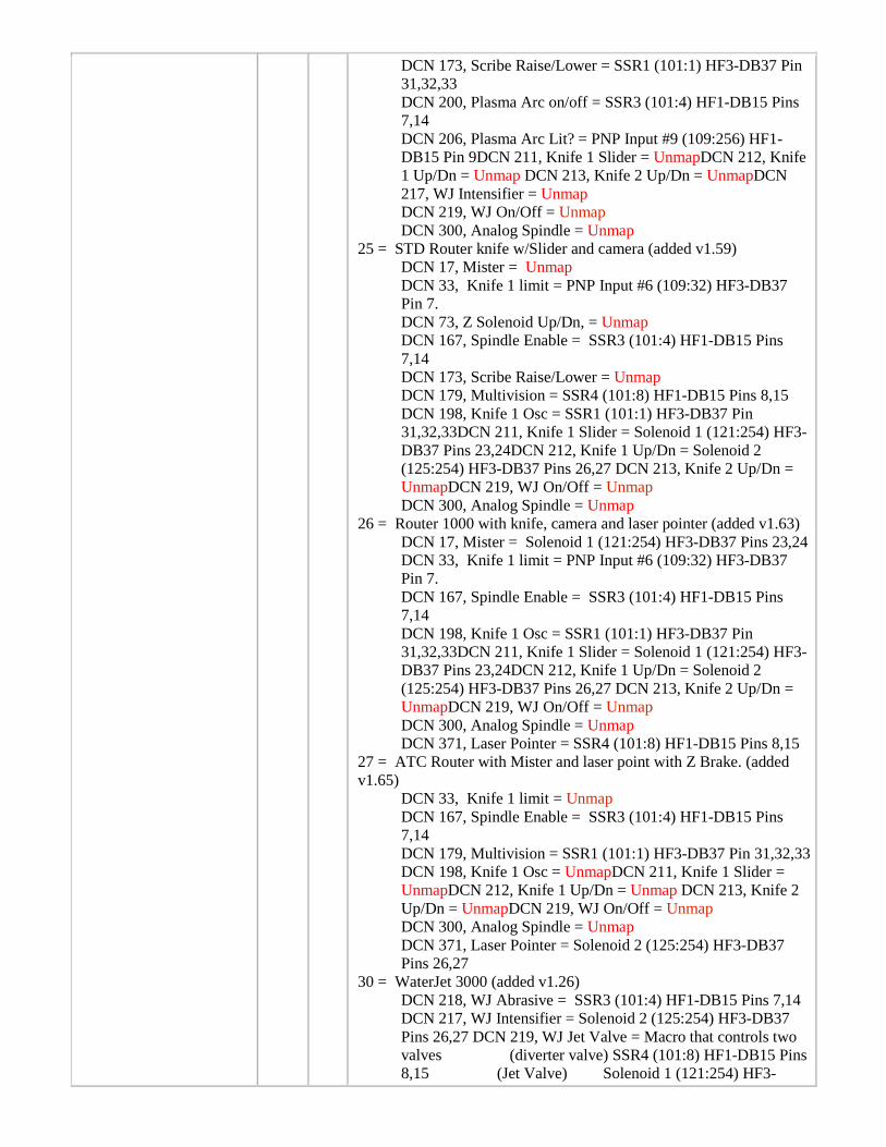
DCN 173, Scribe Raise/Lower = SSR1 (101:1) HF3-DB37 Pin 31,32,33 DCN 200, Plasma Arc on/off = SSR3 (101:4) HF1-DB15 Pins 7,14 DCN 206, Plasma Arc Lit? = PNP Input #9 (109:256) HF1-DB15 Pin 9DCN 211, Knife 1 Slider = UnmapDCN 212, Knife 1 Up/Dn = Unmap DCN 213, Knife 2 Up/Dn = UnmapDCN 217, WJ Intensifier = Unmap DCN 219, WJ On/Off = Unmap DCN 300, Analog Spindle = Unmap
25 = STD Router knife w/Slider and camera (added v1.59) DCN 17, Mister = Unmap DCN 33, Knife 1 limit = PNP Input #6 (109:32) HF3-DB37 Pin 7. DCN 73, Z Solenoid Up/Dn, = Unmap DCN 167, Spindle Enable = SSR3 (101:4) HF1-DB15 Pins 7,14 DCN 173, Scribe Raise/Lower = Unmap DCN 179, Multivision = SSR4 (101:8) HF1-DB15 Pins 8,15 DCN 198, Knife 1 Osc = SSR1 (101:1) HF3-DB37 Pin 31,32,33DCN 211, Knife 1 Slider = Solenoid 1 (121:254) HF3-DB37 Pins 23,24DCN 212, Knife 1 Up/Dn = Solenoid 2 (125:254) HF3-DB37 Pins 26,27 DCN 213, Knife 2 Up/Dn = UnmapDCN 219, WJ On/Off = Unmap DCN 300, Analog Spindle = Unmap
26 = Router 1000 with knife, camera and laser pointer (added v1.63) DCN 17, Mister = Solenoid 1 (121:254) HF3-DB37 Pins 23,24 DCN 33, Knife 1 limit = PNP Input #6 (109:32) HF3-DB37 Pin 7. DCN 167, Spindle Enable = SSR3 (101:4) HF1-DB15 Pins 7,14 DCN 198, Knife 1 Osc = SSR1 (101:1) HF3-DB37 Pin 31,32,33DCN 211, Knife 1 Slider = Solenoid 1 (121:254) HF3-DB37 Pins 23,24DCN 212, Knife 1 Up/Dn = Solenoid 2 (125:254) HF3-DB37 Pins 26,27 DCN 213, Knife 2 Up/Dn = UnmapDCN 219, WJ On/Off = Unmap DCN 300, Analog Spindle = Unmap DCN 371, Laser Pointer = SSR4 (101:8) HF1-DB15 Pins 8,15
27 = ATC Router with Mister and laser point with Z Brake. (added v1.65)
DCN 33, Knife 1 limit = Unmap DCN 167, Spindle Enable = SSR3 (101:4) HF1-DB15 Pins 7,14 DCN 179, Multivision = SSR1 (101:1) HF3-DB37 Pin 31,32,33 DCN 198, Knife 1 Osc = UnmapDCN 211, Knife 1 Slider = UnmapDCN 212, Knife 1 Up/Dn = Unmap DCN 213, Knife 2 Up/Dn = UnmapDCN 219, WJ On/Off = Unmap DCN 300, Analog Spindle = Unmap DCN 371, Laser Pointer = Solenoid 2 (125:254) HF3-DB37 Pins 26,27
30 = WaterJet 3000 (added v1.26) DCN 218, WJ Abrasive = SSR3 (101:4) HF1-DB15 Pins 7,14 DCN 217, WJ Intensifier = Solenoid 2 (125:254) HF3-DB37 Pins 26,27 DCN 219, WJ Jet Valve = Macro that controls two valves (diverter valve) SSR4 (101:8) HF1-DB15 Pins 8,15 (Jet Valve) Solenoid 1 (121:254) HF3-
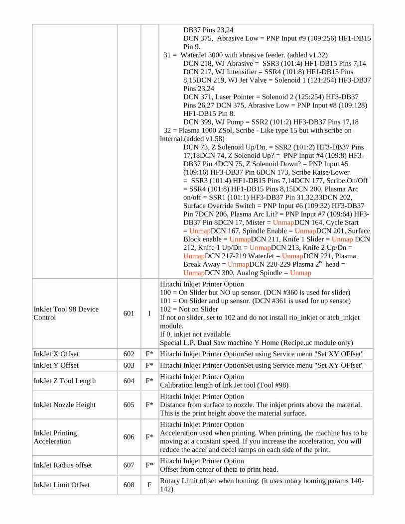
DB37 Pins 23,24 DCN 375, Abrasive Low = PNP Input #9 (109:256) HF1-DB15 Pin 9.
31 = WaterJet 3000 with abrasive feeder. (added v1.32) DCN 218, WJ Abrasive = SSR3 (101:4) HF1-DB15 Pins 7,14 DCN 217, WJ Intensifier = SSR4 (101:8) HF1-DB15 Pins 8,15DCN 219, WJ Jet Valve = Solenoid 1 (121:254) HF3-DB37 Pins 23,24 DCN 371, Laser Pointer = Solenoid 2 (125:254) HF3-DB37 Pins 26,27 DCN 375, Abrasive Low = PNP Input #8 (109:128) HF1-DB15 Pin 8. DCN 399, WJ Pump = SSR2 (101:2) HF3-DB37 Pins 17,18
32 = Plasma 1000 ZSol, Scribe - Like type 15 but with scribe on internal.(added v1.58)
DCN 73, Z Solenoid Up/Dn, = SSR2 (101:2) HF3-DB37 Pins 17,18DCN 74, Z Solenoid Up? = PNP Input #4 (109:8) HF3-DB37 Pin 4DCN 75, Z Solenoid Down? = PNP Input #5 (109:16) HF3-DB37 Pin 6DCN 173, Scribe Raise/Lower = SSR3 (101:4) HF1-DB15 Pins 7,14DCN 177, Scribe On/Off = SSR4 (101:8) HF1-DB15 Pins 8,15DCN 200, Plasma Arc on/off = SSR1 (101:1) HF3-DB37 Pin 31,32,33DCN 202, Surface Override Switch = PNP Input #6 (109:32) HF3-DB37 Pin 7DCN 206, Plasma Arc Lit? = PNP Input #7 (109:64) HF3-DB37 Pin 8DCN 17, Mister = UnmapDCN 164, Cycle Start = UnmapDCN 167, Spindle Enable = UnmapDCN 201, Surface Block enable = UnmapDCN 211, Knife 1 Slider = Unmap DCN 212, Knife 1 Up/Dn = UnmapDCN 213, Knife 2 Up/Dn = UnmapDCN 217-219 WaterJet = UnmapDCN 221, Plasma Break Away = UnmapDCN 220-229 Plasma 2nd head = UnmapDCN 300, Analog Spindle = Unmap
InkJet Tool 98 Device Control 601 I
Hitachi Inkjet Printer Option 100 = On Slider but NO up sensor. (DCN #360 is used for slider) 101 = On Slider and up sensor. (DCN #361 is used for up sensor) 102 = Not on Slider If not on slider, set to 102 and do not install rio_inkjet or atcb_inkjet module. If 0, inkjet not available. Special L.P. Dual Saw machine Y Home (Recipe.uc module only)
InkJet X Offset 602 F* Hitachi Inkjet Printer OptionSet using Service menu "Set XY OFfset" InkJet Y Offset 603 F* Hitachi Inkjet Printer OptionSet using Service menu "Set XY OFfset"
InkJet Z Tool Length 604 F* Hitachi Inkjet Printer Option Calibration length of Ink Jet tool (Tool #98)
InkJet Nozzle Height 605 F* Hitachi Inkjet Printer Option Distance from surface to nozzle. The inkjet prints above the material. This is the print height above the material surface.
InkJet Printing Acceleration 606 F*
Hitachi Inkjet Printer Option Acceleration used when printing. When printing, the machine has to be moving at a constant speed. If you increase the acceleration, you will reduce the accel and decel ramps on each side of the print.
InkJet Radius offset 607 F* Hitachi Inkjet Printer Option Offset from center of theta to print head.
InkJet Limit Offset 608 F Rotary Limit offset when homing. (it uses rotary homing params 140-142)
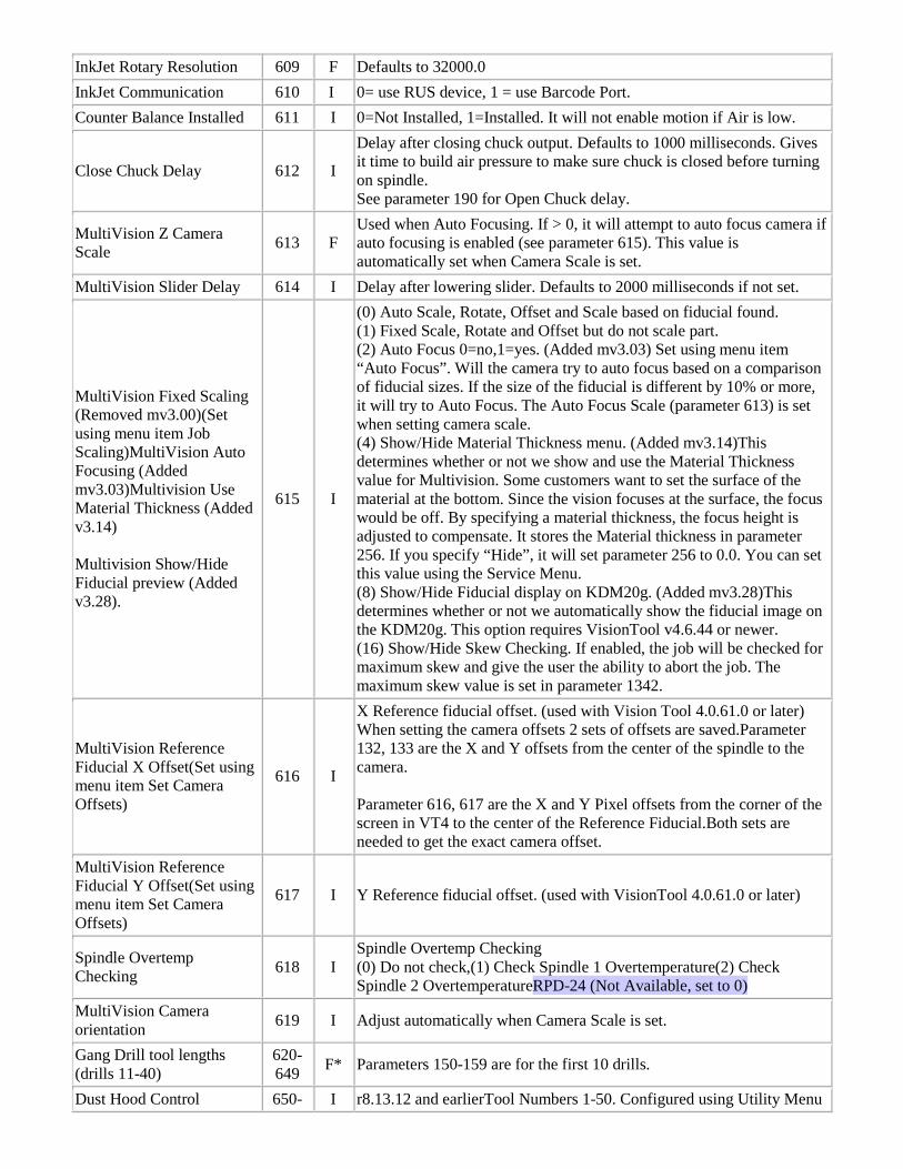
InkJet Rotary Resolution 609 F Defaults to 32000.0 InkJet Communication 610 I 0= use RUS device, 1 = use Barcode Port. Counter Balance Installed 611 I 0=Not Installed, 1=Installed. It will not enable motion if Air is low.
Close Chuck Delay 612 I
Delay after closing chuck output. Defaults to 1000 milliseconds. Gives it time to build air pressure to make sure chuck is closed before turning on spindle. See parameter 190 for Open Chuck delay.
MultiVision Z Camera Scale 613 F
Used when Auto Focusing. If > 0, it will attempt to auto focus camera if auto focusing is enabled (see parameter 615). This value is automatically set when Camera Scale is set.
MultiVision Slider Delay 614 I Delay after lowering slider. Defaults to 2000 milliseconds if not set.
MultiVision Fixed Scaling (Removed mv3.00)(Set using menu item Job Scaling)MultiVision Auto Focusing (Added mv3.03)Multivision Use Material Thickness (Added v3.14) Multivision Show/Hide Fiducial preview (Added v3.28).
615 I
(0) Auto Scale, Rotate, Offset and Scale based on fiducial found. (1) Fixed Scale, Rotate and Offset but do not scale part. (2) Auto Focus 0=no,1=yes. (Added mv3.03) Set using menu item “Auto Focus”. Will the camera try to auto focus based on a comparison of fiducial sizes. If the size of the fiducial is different by 10% or more, it will try to Auto Focus. The Auto Focus Scale (parameter 613) is set when setting camera scale. (4) Show/Hide Material Thickness menu. (Added mv3.14)This determines whether or not we show and use the Material Thickness value for Multivision. Some customers want to set the surface of the material at the bottom. Since the vision focuses at the surface, the focus would be off. By specifying a material thickness, the focus height is adjusted to compensate. It stores the Material thickness in parameter 256. If you specify “Hide”, it will set parameter 256 to 0.0. You can set this value using the Service Menu. (8) Show/Hide Fiducial display on KDM20g. (Added mv3.28)This determines whether or not we automatically show the fiducial image on the KDM20g. This option requires VisionTool v4.6.44 or newer. (16) Show/Hide Skew Checking. If enabled, the job will be checked for maximum skew and give the user the ability to abort the job. The maximum skew value is set in parameter 1342.
MultiVision Reference Fiducial X Offset(Set using menu item Set Camera Offsets)
616 I
X Reference fiducial offset. (used with Vision Tool 4.0.61.0 or later) When setting the camera offsets 2 sets of offsets are saved.Parameter 132, 133 are the X and Y offsets from the center of the spindle to the camera. Parameter 616, 617 are the X and Y Pixel offsets from the corner of the screen in VT4 to the center of the Reference Fiducial.Both sets are needed to get the exact camera offset.
MultiVision Reference Fiducial Y Offset(Set using menu item Set Camera Offsets)
617 I Y Reference fiducial offset. (used with VisionTool 4.0.61.0 or later)
Spindle Overtemp Checking 618 I
Spindle Overtemp Checking (0) Do not check,(1) Check Spindle 1 Overtemperature(2) Check Spindle 2 OvertemperatureRPD-24 (Not Available, set to 0)
MultiVision Camera orientation 619 I Adjust automatically when Camera Scale is set.
Gang Drill tool lengths (drills 11-40)
620-649 F* Parameters 150-159 are for the first 10 drills.
Dust Hood Control 650- I r8.13.12 and earlierTool Numbers 1-50. Configured using Utility Menu
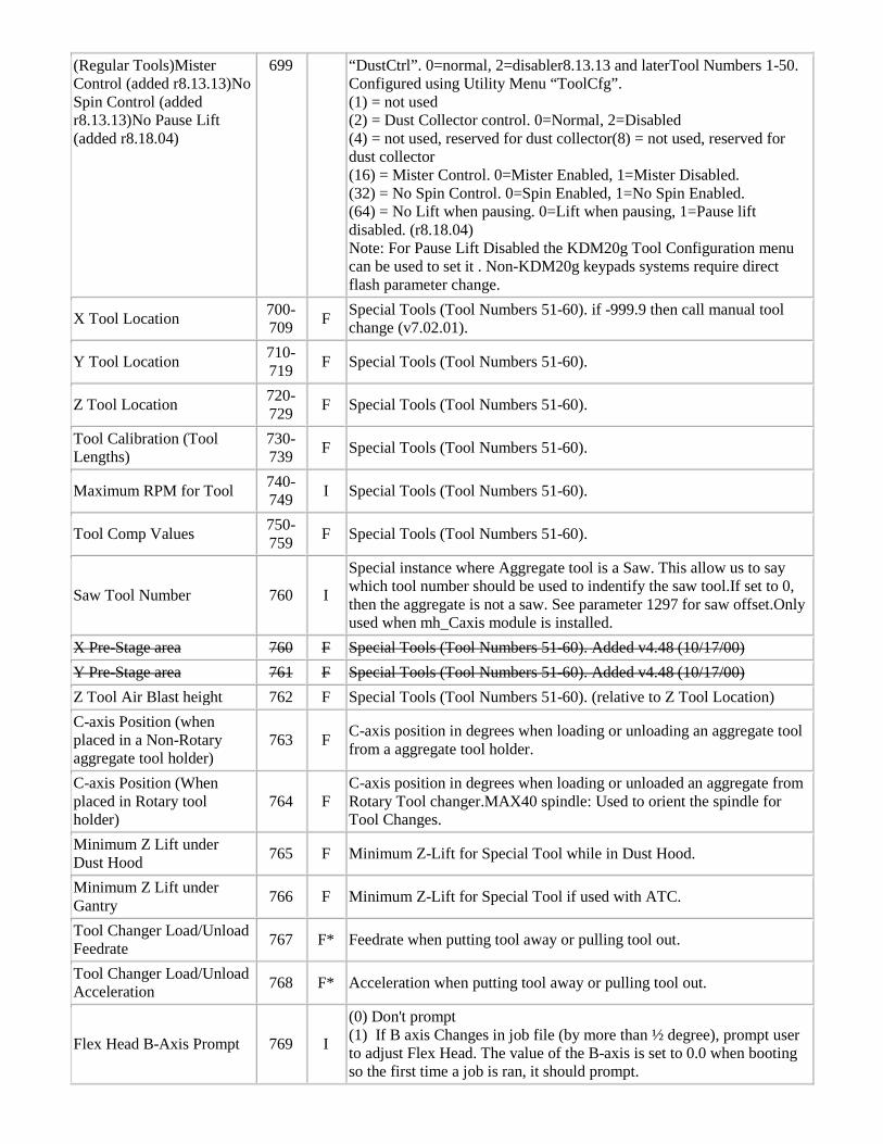
(Regular Tools)Mister Control (added r8.13.13)No Spin Control (added r8.13.13)No Pause Lift (added r8.18.04)
699 “DustCtrl”. 0=normal, 2=disabler8.13.13 and laterTool Numbers 1-50. Configured using Utility Menu “ToolCfg”. (1) = not used (2) = Dust Collector control. 0=Normal, 2=Disabled (4) = not used, reserved for dust collector(8) = not used, reserved for dust collector (16) = Mister Control. 0=Mister Enabled, 1=Mister Disabled. (32) = No Spin Control. 0=Spin Enabled, 1=No Spin Enabled. (64) = No Lift when pausing. 0=Lift when pausing, 1=Pause lift disabled. (r8.18.04) Note: For Pause Lift Disabled the KDM20g Tool Configuration menu can be used to set it . Non-KDM20g keypads systems require direct flash parameter change.
X Tool Location 700-709 F Special Tools (Tool Numbers 51-60). if -999.9 then call manual tool
change (v7.02.01).
Y Tool Location 710-719 F Special Tools (Tool Numbers 51-60).
Z Tool Location 720-729 F Special Tools (Tool Numbers 51-60).
Tool Calibration (Tool Lengths)
730-739 F Special Tools (Tool Numbers 51-60).
Maximum RPM for Tool 740-749 I Special Tools (Tool Numbers 51-60).
Tool Comp Values 750-759 F Special Tools (Tool Numbers 51-60).
Saw Tool Number 760 I
Special instance where Aggregate tool is a Saw. This allow us to say which tool number should be used to indentify the saw tool.If set to 0, then the aggregate is not a saw. See parameter 1297 for saw offset.Only used when mh_Caxis module is installed.
X Pre-Stage area 760 F Special Tools (Tool Numbers 51-60). Added v4.48 (10/17/00) Y Pre-Stage area 761 F Special Tools (Tool Numbers 51-60). Added v4.48 (10/17/00) Z Tool Air Blast height 762 F Special Tools (Tool Numbers 51-60). (relative to Z Tool Location) C-axis Position (when placed in a Non-Rotary aggregate tool holder)
763 F C-axis position in degrees when loading or unloading an aggregate tool from a aggregate tool holder.
C-axis Position (When placed in Rotary tool holder)
764 F C-axis position in degrees when loading or unloaded an aggregate from Rotary Tool changer.MAX40 spindle: Used to orient the spindle for Tool Changes.
Minimum Z Lift under Dust Hood 765 F Minimum Z-Lift for Special Tool while in Dust Hood.
Minimum Z Lift under Gantry 766 F Minimum Z-Lift for Special Tool if used with ATC.
Tool Changer Load/Unload Feedrate 767 F* Feedrate when putting tool away or pulling tool out.
Tool Changer Load/Unload Acceleration 768 F* Acceleration when putting tool away or pulling tool out.
Flex Head B-Axis Prompt 769 I
(0) Don't prompt (1) If B axis Changes in job file (by more than ½ degree), prompt user to adjust Flex Head. The value of the B-axis is set to 0.0 when booting so the first time a job is ran, it should prompt.
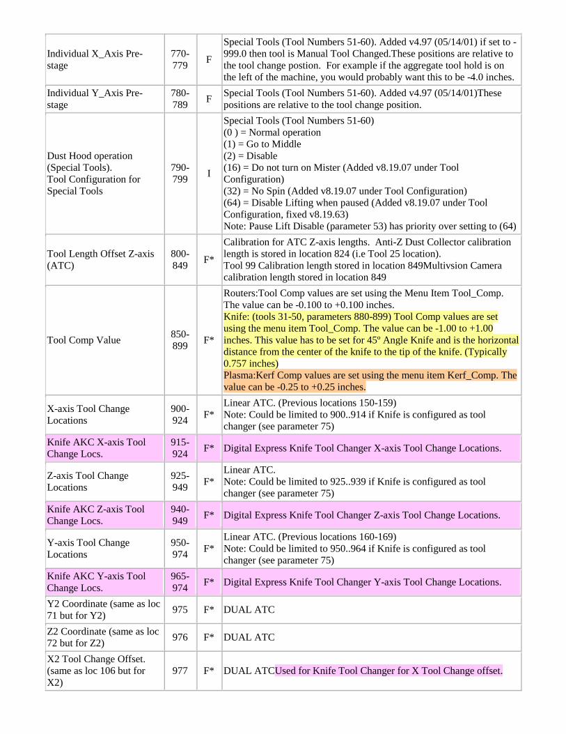
Individual X_Axis Pre-stage
770-779 F
Special Tools (Tool Numbers 51-60). Added v4.97 (05/14/01) if set to -999.0 then tool is Manual Tool Changed.These positions are relative to the tool change postion. For example if the aggregate tool hold is on the left of the machine, you would probably want this to be -4.0 inches.
Individual Y_Axis Pre-stage
780-789 F Special Tools (Tool Numbers 51-60). Added v4.97 (05/14/01)These
positions are relative to the tool change position.
Dust Hood operation (Special Tools). Tool Configuration for Special Tools
790-799 I
Special Tools (Tool Numbers 51-60) (0 ) = Normal operation (1) = Go to Middle (2) = Disable (16) = Do not turn on Mister (Added v8.19.07 under Tool Configuration) (32) = No Spin (Added v8.19.07 under Tool Configuration) (64) = Disable Lifting when paused (Added v8.19.07 under Tool Configuration, fixed v8.19.63) Note: Pause Lift Disable (parameter 53) has priority over setting to (64)
Tool Length Offset Z-axis (ATC)
800-849 F*
Calibration for ATC Z-axis lengths. Anti-Z Dust Collector calibration length is stored in location 824 (i.e Tool 25 location). Tool 99 Calibration length stored in location 849Multivsion Camera calibration length stored in location 849
Tool Comp Value 850-899 F*
Routers:Tool Comp values are set using the Menu Item Tool_Comp. The value can be -0.100 to +0.100 inches. Knife: (tools 31-50, parameters 880-899) Tool Comp values are set using the menu item Tool_Comp. The value can be -1.00 to +1.00 inches. This value has to be set for 45º Angle Knife and is the horizontal distance from the center of the knife to the tip of the knife. (Typically 0.757 inches) Plasma:Kerf Comp values are set using the menu item Kerf_Comp. The value can be -0.25 to +0.25 inches.
X-axis Tool Change Locations
900-924 F*
Linear ATC. (Previous locations 150-159) Note: Could be limited to 900..914 if Knife is configured as tool changer (see parameter 75)
Knife AKC X-axis Tool Change Locs.
915-924 F* Digital Express Knife Tool Changer X-axis Tool Change Locations.
Z-axis Tool Change Locations
925-949 F*
Linear ATC. Note: Could be limited to 925..939 if Knife is configured as tool changer (see parameter 75)
Knife AKC Z-axis Tool Change Locs.
940-949 F* Digital Express Knife Tool Changer Z-axis Tool Change Locations.
Y-axis Tool Change Locations
950-974 F*
Linear ATC. (Previous locations 160-169) Note: Could be limited to 950..964 if Knife is configured as tool changer (see parameter 75)
Knife AKC Y-axis Tool Change Locs.
965-974 F* Digital Express Knife Tool Changer Y-axis Tool Change Locations.
Y2 Coordinate (same as loc 71 but for Y2) 975 F* DUAL ATC
Z2 Coordinate (same as loc 72 but for Z2) 976 F* DUAL ATC
X2 Tool Change Offset. (same as loc 106 but for X2)
977 F* DUAL ATCUsed for Knife Tool Changer for X Tool Change offset.
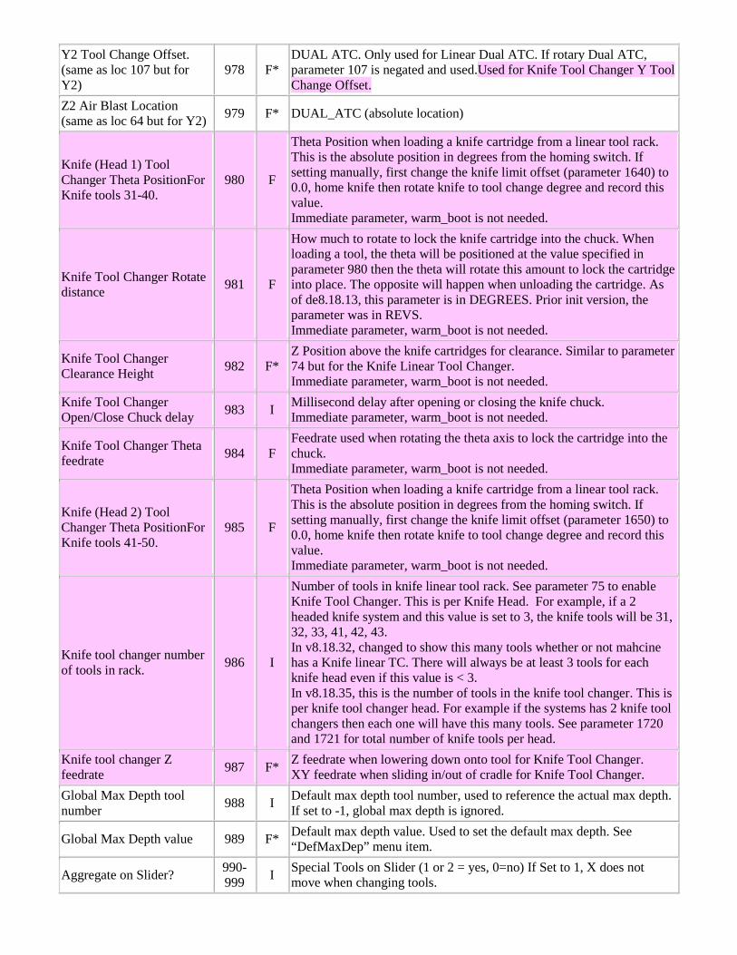
Y2 Tool Change Offset. (same as loc 107 but for Y2)
978 F* DUAL ATC. Only used for Linear Dual ATC. If rotary Dual ATC, parameter 107 is negated and used.Used for Knife Tool Changer Y Tool Change Offset.
Z2 Air Blast Location (same as loc 64 but for Y2) 979 F* DUAL_ATC (absolute location)
Knife (Head 1) Tool Changer Theta PositionFor Knife tools 31-40.
980 F
Theta Position when loading a knife cartridge from a linear tool rack. This is the absolute position in degrees from the homing switch. If setting manually, first change the knife limit offset (parameter 1640) to 0.0, home knife then rotate knife to tool change degree and record this value. Immediate parameter, warm_boot is not needed.
Knife Tool Changer Rotate distance 981 F
How much to rotate to lock the knife cartridge into the chuck. When loading a tool, the theta will be positioned at the value specified in parameter 980 then the theta will rotate this amount to lock the cartridge into place. The opposite will happen when unloading the cartridge. As of de8.18.13, this parameter is in DEGREES. Prior init version, the parameter was in REVS. Immediate parameter, warm_boot is not needed.
Knife Tool Changer Clearance Height 982 F*
Z Position above the knife cartridges for clearance. Similar to parameter 74 but for the Knife Linear Tool Changer. Immediate parameter, warm_boot is not needed.
Knife Tool Changer Open/Close Chuck delay 983 I Millisecond delay after opening or closing the knife chuck.
Immediate parameter, warm_boot is not needed.
Knife Tool Changer Theta feedrate 984 F
Feedrate used when rotating the theta axis to lock the cartridge into the chuck. Immediate parameter, warm_boot is not needed.
Knife (Head 2) Tool Changer Theta PositionFor Knife tools 41-50.
985 F
Theta Position when loading a knife cartridge from a linear tool rack. This is the absolute position in degrees from the homing switch. If setting manually, first change the knife limit offset (parameter 1650) to 0.0, home knife then rotate knife to tool change degree and record this value. Immediate parameter, warm_boot is not needed.
Knife tool changer number of tools in rack. 986 I
Number of tools in knife linear tool rack. See parameter 75 to enable Knife Tool Changer. This is per Knife Head. For example, if a 2 headed knife system and this value is set to 3, the knife tools will be 31, 32, 33, 41, 42, 43. In v8.18.32, changed to show this many tools whether or not mahcine has a Knife linear TC. There will always be at least 3 tools for each knife head even if this value is < 3. In v8.18.35, this is the number of tools in the knife tool changer. This is per knife tool changer head. For example if the systems has 2 knife tool changers then each one will have this many tools. See parameter 1720 and 1721 for total number of knife tools per head.
Knife tool changer Z feedrate 987 F* Z feedrate when lowering down onto tool for Knife Tool Changer.
XY feedrate when sliding in/out of cradle for Knife Tool Changer. Global Max Depth tool number 988 I Default max depth tool number, used to reference the actual max depth.
If set to -1, global max depth is ignored.
Global Max Depth value 989 F* Default max depth value. Used to set the default max depth. See “DefMaxDep” menu item.
Aggregate on Slider? 990-999 I Special Tools on Slider (1 or 2 = yes, 0=no) If Set to 1, X does not
move when changing tools.
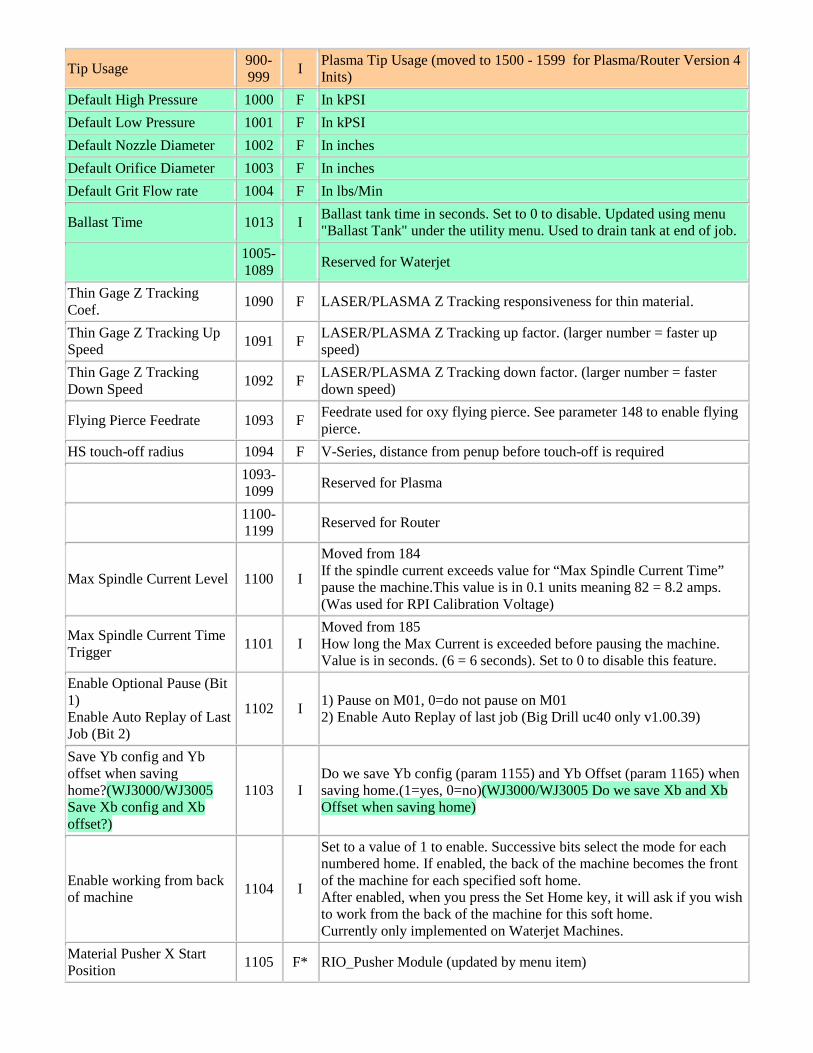
Tip Usage 900-999 I Plasma Tip Usage (moved to 1500 - 1599 for Plasma/Router Version 4
Inits) Default High Pressure 1000 F In kPSI Default Low Pressure 1001 F In kPSI Default Nozzle Diameter 1002 F In inches Default Orifice Diameter 1003 F In inches Default Grit Flow rate 1004 F In lbs/Min
Ballast Time 1013 I Ballast tank time in seconds. Set to 0 to disable. Updated using menu "Ballast Tank" under the utility menu. Used to drain tank at end of job.
1005-1089 Reserved for Waterjet
Thin Gage Z Tracking Coef. 1090 F LASER/PLASMA Z Tracking responsiveness for thin material.
Thin Gage Z Tracking Up Speed 1091 F LASER/PLASMA Z Tracking up factor. (larger number = faster up
speed) Thin Gage Z Tracking Down Speed 1092 F LASER/PLASMA Z Tracking down factor. (larger number = faster
down speed)
Flying Pierce Feedrate 1093 F Feedrate used for oxy flying pierce. See parameter 148 to enable flying pierce.
HS touch-off radius 1094 F V-Series, distance from penup before touch-off is required
1093-1099 Reserved for Plasma
1100-1199 Reserved for Router
Max Spindle Current Level 1100 I
Moved from 184 If the spindle current exceeds value for “Max Spindle Current Time” pause the machine.This value is in 0.1 units meaning 82 = 8.2 amps. (Was used for RPI Calibration Voltage)
Max Spindle Current Time Trigger 1101 I
Moved from 185 How long the Max Current is exceeded before pausing the machine. Value is in seconds. (6 = 6 seconds). Set to 0 to disable this feature.
Enable Optional Pause (Bit 1) Enable Auto Replay of Last Job (Bit 2)
1102 I 1) Pause on M01, 0=do not pause on M01 2) Enable Auto Replay of last job (Big Drill uc40 only v1.00.39)
Save Yb config and Yb offset when saving home?(WJ3000/WJ3005 Save Xb config and Xb offset?)
1103 I Do we save Yb config (param 1155) and Yb Offset (param 1165) when saving home.(1=yes, 0=no)(WJ3000/WJ3005 Do we save Xb and Xb Offset when saving home)
Enable working from back of machine 1104 I
Set to a value of 1 to enable. Successive bits select the mode for each numbered home. If enabled, the back of the machine becomes the front of the machine for each specified soft home. After enabled, when you press the Set Home key, it will ask if you wish to work from the back of the machine for this soft home. Currently only implemented on Waterjet Machines.
Material Pusher X Start Position 1105 F* RIO_Pusher Module (updated by menu item)
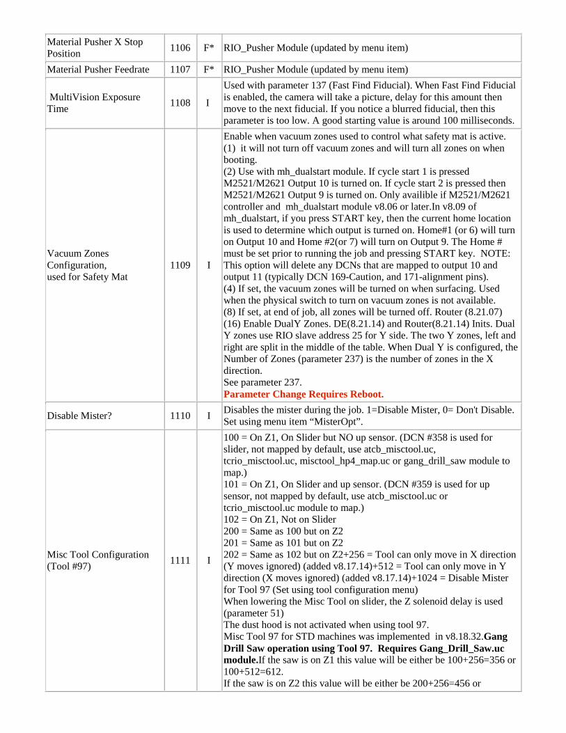
Material Pusher X Stop Position 1106 F* RIO_Pusher Module (updated by menu item)
Material Pusher Feedrate 1107 F* RIO_Pusher Module (updated by menu item)
MultiVision Exposure Time 1108 I
Used with parameter 137 (Fast Find Fiducial). When Fast Find Fiducial is enabled, the camera will take a picture, delay for this amount then move to the next fiducial. If you notice a blurred fiducial, then this parameter is too low. A good starting value is around 100 milliseconds.
Vacuum Zones Configuration, used for Safety Mat
1109 I
Enable when vacuum zones used to control what safety mat is active. (1) it will not turn off vacuum zones and will turn all zones on when booting. (2) Use with mh_dualstart module. If cycle start 1 is pressed M2521/M2621 Output 10 is turned on. If cycle start 2 is pressed then M2521/M2621 Output 9 is turned on. Only availible if M2521/M2621 controller and mh_dualstart module v8.06 or later.In v8.09 of mh_dualstart, if you press START key, then the current home location is used to determine which output is turned on. Home#1 (or 6) will turn on Output 10 and Home #2(or 7) will turn on Output 9. The Home # must be set prior to running the job and pressing START key. NOTE: This option will delete any DCNs that are mapped to output 10 and output 11 (typically DCN 169-Caution, and 171-alignment pins). (4) If set, the vacuum zones will be turned on when surfacing. Used when the physical switch to turn on vacuum zones is not available. (8) If set, at end of job, all zones will be turned off. Router (8.21.07) (16) Enable DualY Zones. DE(8.21.14) and Router(8.21.14) Inits. Dual Y zones use RIO slave address 25 for Y side. The two Y zones, left and right are split in the middle of the table. When Dual Y is configured, the Number of Zones (parameter 237) is the number of zones in the X direction. See parameter 237. Parameter Change Requires Reboot.
Disable Mister? 1110 I Disables the mister during the job. 1=Disable Mister, 0= Don't Disable. Set using menu item “MisterOpt”.
Misc Tool Configuration (Tool #97) 1111 I
100 = On Z1, On Slider but NO up sensor. (DCN #358 is used for slider, not mapped by default, use atcb_misctool.uc, tcrio_misctool.uc, misctool_hp4_map.uc or gang_drill_saw module to map.) 101 = On Z1, On Slider and up sensor. (DCN #359 is used for up sensor, not mapped by default, use atcb_misctool.uc or tcrio_misctool.uc module to map.) 102 = On Z1, Not on Slider 200 = Same as 100 but on Z2 201 = Same as 101 but on Z2 202 = Same as 102 but on Z2+256 = Tool can only move in X direction (Y moves ignored) (added v8.17.14)+512 = Tool can only move in Y direction (X moves ignored) (added v8.17.14)+1024 = Disable Mister for Tool 97 (Set using tool configuration menu) When lowering the Misc Tool on slider, the Z solenoid delay is used (parameter 51) The dust hood is not activated when using tool 97. Misc Tool 97 for STD machines was implemented in v8.18.32.Gang Drill Saw operation using Tool 97. Requires Gang_Drill_Saw.uc module.If the saw is on Z1 this value will be either be 100+256=356 or 100+512=612. If the saw is on Z2 this value will be either be 200+256=456 or
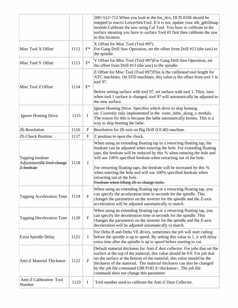
200+512=712.When you look at the list_dcn, DCN #358 should be mapped to macro LowerSawTool. If it is not, update your mh_gdrillmap module.Calibrate the saw using Cal Tool. You have to calibrate to the surface meaning you have to surface Tool #1 first then calibrate the saw to this location.
Misc Tool X Offset 1112 F* X Offset for Misc Tool (Tool #97). For Gang Drill Saw Operation, set the offset from Drill #13 (the saw) to the spindle.
Misc Tool Y Offset 1113 F* Y Offset for Misc Tool (Tool #97)For Gang Drill Saw Operation, set the offset from Drill #13 (the saw) to the spindle.
Misc Tool Z Offset 1114 F*
Z Offset for Misc Tool (Tool #97)This is the calibrated tool length for ATC machines. On STD machines, this value is the offset from tool 1 to tool 97. Before setting surface with tool 97, set surface with tool 1. Then, later when tool 1 surface is changed, tool 97 will automatically be adjusted to the new surface.
Ignore Homing Drive 1115 I
Ignore Homing Drive. Specifies which drive to skip homing on. Currently only implemented in the route_lathe_along_x module. The reason for this is because the lathe automatically homes. This is a way to skip homing the lathe.
Zb Resolution 1116 F Resolution for Zb axis on Big Drill (UC40) machine. Zb Chuck Position 1117 F Z position to open the chuck.
Tapping feedrate AdjustmentZb Tool change Z feedrate
1118 I
When using an extending floating tap or a retracting floating tap, the feedrate can be adjusted when entering the hole. For extending floating taps, the feedrate will be reduced by this % when entering the hole and will use 100% specified feedrate when retracting out of the hole. For retracting floating taps, the feedrate will be increased by this % when entering the hole and will use 100% specified feedrate when retracting out of the hole. Feedrate when lifting Zb to change tools.
Tapping Acceleration Time 1119 F
When using an extending floating tap or a retracting floating tap, you can specify the acceleration time in seconds for the spindle. This changes the parameters on the inverter for the spindle and the Z-axis acceleration will be adjusted automatically to match.
Tapping Deceleration Time 1120 F
When using an extending floating tap or a retracting floating tap, you can specify the deceleration time in seconds for the spindle. This changes the parameters on the inverter for the spindle and the Z-axis deceleration will be adjusted automatically to match.
Extra Spindle Delay 1121 I For Delta B and Delta VE drives, sometimes the job will start cutting before the spindle is up to speed. By setting this value to 1, it will delay extra time after the spindle is up to speed before starting to cut.
Anti-Z Material Thickness 1122 F
Default material thickness for Anti-Z dust collector. For jobs that set the surface at the top of the material, this value should be 0.0. For job that set the surface at the bottom of the material, this value should be the thickness of the material. The material thickness can also be changed by the job file command G98 P185 E<thickness>. The job file command does not change this parameter.
Anti-Z Calibration Tool Number 1123 I Tool number used to calibrate the Anti-Z Dust Collector.
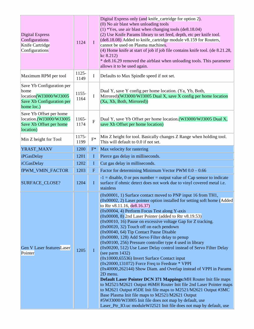
Digital Express Configurations Knife Cartridge Configurations
1124 I
Digital Express only (and knife_cartridge for option 2). (0) No air blast when unloading tools (1) *Yes, use air blast when changing tools (de8.18.04) (2) Use Knife Params library to set feed, depth, etc per knife tool. (de8.18.08) Added to knife_cartridge module v8.159 for Routers, cannot be used on Plasma machines. (4) Home knife at start of job if job file contains knife tool. (de 8.21.28, kc 8.212) * de8.16.29 removed the airblast when unloading tools. This parameter allows it to be used again.
Maximum RPM per tool 1125-1149 I Defaults to Max Spindle speed if not set.
Save Yb Configuration per home location(WJ3000/WJ3005 Save Xb Configuration per home loc.)
1155-1164 I
Dual Y, save Y config per home location. (Ya, Yb, Both, Mirrored)(WJ3000/WJ3005 Dual X, save X config per home location (Xa, Xb, Both, Mirrored))
Save Yb Offset per home location.(WJ3000/WJ3005 Save Xb Offset per home location)
1165-1174 F Dual Y, save Yb Offset per home location.(WJ3000/WJ3005 Dual X,
save Xb Offset per home location)
Min Z height for Tool 1175-1199 F* Min Z height for tool. Basically changes Z Range when holding tool.
This will default to 0.0 if not set. YRAST_MAXV 1200 F* Max velocity for rastering iPGasDelay 1201 I Pierce gas delay in milliseconds. iCGasDelay 1202 I Cut gas delay in milliseconds. fPWM_VMIN_FACTOR 1203 F Factor for determining Minimum Vector PWM 0.0 – 0.66
SURFACE_CLOSE? 1204 I -1 = disable, 0 or pos number = output value of Cap sensor to indicate surface if ohmic detect does not work due to vinyl covered metal i.e. stainless
Gen V Laser featuresLaser Pointer 1205 I
(0x00001, 1) Surface contact moved to PNP input 16 from TH1, (0x00002, 2) Laser pointer option installed for setting soft home (Added to Rtr v8.11.16, de8.16.37) (0x00004, 4) Perform Focus Test along Y-axis (0x00008, 8) 2nd Laser Pointer (added to Rtr v8.19.53) (0x00010, 16) Pause on excessive voltage Gap for Z tracking. (0x00020, 32) Touch off on each pendown (0x00040, 64) Tip Contact Pause Disable (0x00080, 128) Add Servo Filter delay to penup (0x00100, 256) Pressure controller type 4 used in library (0x00200, 512) Use Laser Delay control instead of Servo Filter Delay (see parm 1432) (0x10000,65536) Invert Surface Contact input (0x20000,131072) Force Freq to Feedrate * VPPI (0x40000,262144) Show Diam. and Overlap instead of VPPI in Params 2D menu. Default Laser Pointer DCN 371 Mappings:MH Router Init file maps to M2521/M2621 Output #6MH Router Init file 2nd Laser Pointer maps to M2621 Output #5DE Init file maps to M2521/M2621 Output #3MC Base Plasma Init file maps to M2521/M2621 Output #5WJ3000/WJ3005 Init file does not map by default, use Laser_Ptr_IO.uc moduleWJ2521 Init file does not map by default, use
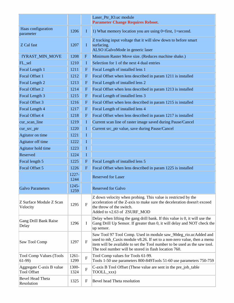
Laser_Ptr_IO.uc module Parameter Change Requires Reboot.
Haas configuration parameter 1206 I 1) What memory location you are using 0=first, 1=second.
Z Cal fast 1207 I Z tracking input voltage that it will slew down to before smart surfacing. ALSO iGalvoMode in generic laser
fYRAST_MIN_MOVE 1208 F Minimum Raster Move size. (Reduces machine shake.) FL_sel 1210 I Selection for 1 of the next 4 dual entries Focal Length 1 1211 F Focal Length of installed lens 1 Focal Offset 1 1212 F Focal Offset when lens described in param 1211 is installed Focal Length 2 1213 F Focal Length of installed lens 2 Focal Offset 2 1214 F Focal Offset when lens described in param 1213 is installed Focal Length 3 1215 F Focal Length of installed lens 3 Focal Offset 3 1216 F Focal Offset when lens described in param 1215 is installed Focal Length 4 1217 F Focal Length of installed lens 4 Focal Offset 4 1218 F Focal Offset when lens described in param 1217 is installed cur_scan_line 1219 I Current scan line of raster image saved during Pause/Cancel cur_src_ptr 1220 I Current src_ptr value, save during Pause/Cancel Agitator on time 1221 I Agitator off time 1222 I Agitator hold time 1223 I Reserved 1224 I Focal length 5 1225 F Focal Length of installed lens 5 Focal Offset 5 1226 F Focal Offset when lens described in param 1225 is installed
1227-1244 Reserved for Laser
Galvo Parameters 1245-1259 Reserved for Galvo
Z Surface Module Z Scan Velocity 1295 F
Z down velocity when probing. This value is restricted by the acceleration of the Z-axis to make sure the deceleration doesn't exceed the throw of the switch. Added to v2.63 of ZSURF_MOD
Gang Drill Bank Raise Delay 1296 I
Delay when lifting the gang drill bank. If this value is 0, it will use the Gang Drill Up Sensor. If greater than 0, it will delay and NOT check the up sensor.
Saw Tool Comp 1297 F
Saw Tool 97 Tool Comp. Used in module saw_90deg_rio.ucAdded and used to mh_Caxis module v8.26. If set to a non-zero value, then a menu item will be available to set the Tool number to be used as the saw tool. The tool number will be stored in flash location 760.
Tool Comp Values (Tools 61-99)
1261-1299 F Tool Comp values for Tools 61-99.
Tools 1-50 use parameters 800-849Tools 51-60 use parameters 750-759 Aggregate C-axis B value Tool Offset
1300-1324 F C-axis B Tool Offset (These value are sent in the pre_job_table
TOOLL_xxx) Bevel Head Theta Resolution 1325 F Bevel head Theta resolution
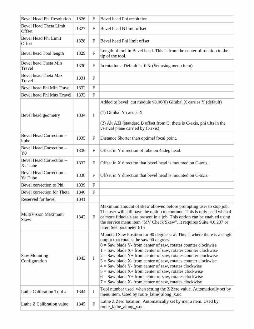
Bevel Head Phi Resolution 1326 F Bevel head Phi resolution Bevel Head Theta Limit Offset 1327 F Bevel head B limit offset
Bevel Head Phi Limit Offset 1328 F Bevel head Phi limit offset
Bevel head Tool length 1329 F Length of tool in Bevel head. This is from the center of rotation to the tip of the tool.
Bevel head Theta Min Travel 1330 F In rotations. Default is -0.3. (Set using menu item)
Bevel head Theta Max Travel 1331 F
Bevel head Phi Min Travel 1332 F Bevel head Phi Max Travel 1333 F
Bevel head geometry 1334 I
Added to bevel_cut module v8.06(0) Gimbal X carries Y (default) (1) Gimbal Y carries X (2) Alt AZI (standard B offset from C, theta is C-axis, phi tilts in the vertical plane carried by C-axis)
Bevel Head Correction -- ltube 1335 F Distance Shorter than optimal focal point.
Bevel Head Correction -- Y0 1336 F Offset in Y direction of tube on 45deg head.
Bevel Head Correction -- Xc Tube 1337 F Offset in X direction that bevel head is mounted on C-axis.
Bevel Head Correction -- Yc Tube 1338 F Offset in Y direction that bevel head is mounted on C-axis.
Bevel correction to Phi 1339 F Bevel correction for Theta 1340 F Reserved for bevel 1341
MultiVision Maximum Skew 1342 F
Maximum amount of skew allowed before prompting user to stop job. The user will still have the option to continue. This is only used when 4 or more fiducials are present in a job. This option can be enabled using the service menu item "MV Check Skew". It requires Suite 4.6.237 or later. See parameter 615
Saw Mounting Configuration 1343 I
Mounted Saw Position for 90 degree saw. This is where there is a single output that rotates the saw 90 degrees. 0 = Saw blade Y- from center of saw, rotates counter clockwise 1 = Saw blade X+ from center of saw, rotates counter clockwise 2 = Saw blade Y+ from center of saw, rotates counter clockwise 3 = Saw blade X- from center of saw, rotates counter clockwise 4 = Saw blade Y- from center of saw, rotates clockwise 5 = Saw blade X+ from center of saw, rotates clockwise 6 = Saw blade Y+ from center of saw, rotates clockwise 7 = Saw blade X- from center of saw, rotates clockwise
Lathe Calibration Tool # 1344 I Tool number used when setting the Z Zero value. Automatically set by menu item. Used by route_lathe_along_x.uc
Lathe Z Calibration value 1345 F Lathe Z Zero location. Automatically set by menu item. Used by route_lathe_along_x.uc
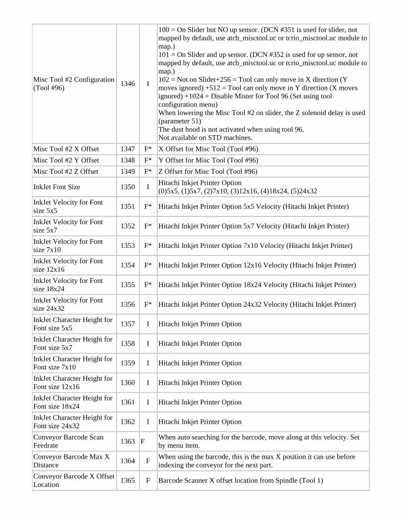
Misc Tool #2 Configuration (Tool #96) 1346 I
100 = On Slider but NO up sensor. (DCN #351 is used for slider, not mapped by default, use atcb_misctool.uc or tcrio_misctool.uc module to map.) 101 = On Slider and up sensor. (DCN #352 is used for up sensor, not mapped by default, use atcb_misctool.uc or tcrio_misctool.uc module to map.) 102 = Not on Slider+256 = Tool can only move in X direction (Y moves ignored) +512 = Tool can only move in Y direction (X moves ignored) +1024 = Disable Mister for Tool 96 (Set using tool configuration menu) When lowering the Misc Tool #2 on slider, the Z solenoid delay is used (parameter 51) The dust hood is not activated when using tool 96. Not available on STD machines.
Misc Tool #2 X Offset 1347 F* X Offset for Misc Tool (Tool #96) Misc Tool #2 Y Offset 1348 F* Y Offset for Misc Tool (Tool #96) Misc Tool #2 Z Offset 1349 F* Z Offset for Misc Tool (Tool #96)
InkJet Font Size 1350 I Hitachi Inkjet Printer Option (0)5x5, (1)5x7, (2)7x10, (3)12x16, (4)18x24, (5)24x32
InkJet Velocity for Font size 5x5 1351 F* Hitachi Inkjet Printer Option 5x5 Velocity (Hitachi Inkjet Printer)
InkJet Velocity for Font size 5x7 1352 F* Hitachi Inkjet Printer Option 5x7 Velocity (Hitachi Inkjet Printer)
InkJet Velocity for Font size 7x10 1353 F* Hitachi Inkjet Printer Option 7x10 Velocity (Hitachi Inkjet Printer)
InkJet Velocity for Font size 12x16 1354 F* Hitachi Inkjet Printer Option 12x16 Velocity (Hitachi Inkjet Printer)
InkJet Velocity for Font size 18x24 1355 F* Hitachi Inkjet Printer Option 18x24 Velocity (Hitachi Inkjet Printer)
InkJet Velocity for Font size 24x32 1356 F* Hitachi Inkjet Printer Option 24x32 Velocity (Hitachi Inkjet Printer)
InkJet Character Height for Font size 5x5 1357 I Hitachi Inkjet Printer Option
InkJet Character Height for Font size 5x7 1358 I Hitachi Inkjet Printer Option
InkJet Character Height for Font size 7x10 1359 I Hitachi Inkjet Printer Option
InkJet Character Height for Font size 12x16 1360 I Hitachi Inkjet Printer Option
InkJet Character Height for Font size 18x24 1361 I Hitachi Inkjet Printer Option
InkJet Character Height for Font size 24x32 1362 I Hitachi Inkjet Printer Option
Conveyor Barcode Scan Feedrate 1363 F When auto searching for the barcode, move along at this velocity. Set
by menu item. Conveyor Barcode Max X Distance 1364 F When using the barcode, this is the max X position it can use before
indexing the conveyor for the next part. Conveyor Barcode X Offset Location 1365 F Barcode Scanner X offset location from Spindle (Tool 1)
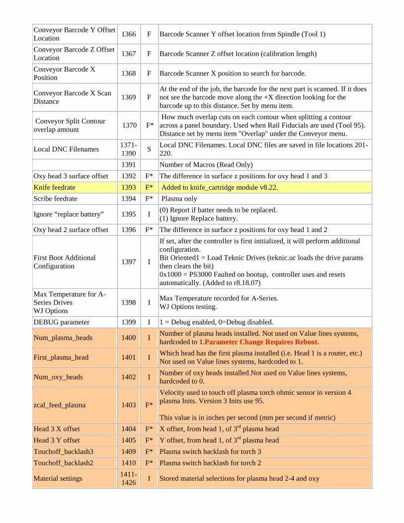
Conveyor Barcode Y Offset Location 1366 F Barcode Scanner Y offset location from Spindle (Tool 1)
Conveyor Barcode Z Offset Location 1367 F Barcode Scanner Z offset location (calibration length)
Conveyor Barcode X Position 1368 F Barcode Scanner X position to search for barcode.
Conveyor Barcode X Scan Distance 1369 F
At the end of the job, the barcode for the next part is scanned. If it does not see the barcode move along the +X direction looking for the barcode up to this distance. Set by menu item.
Conveyor Split Contour overlap amount 1370 F*
How much overlap cuts on each contour when splitting a contour across a panel boundary. Used when Rail Fiducials are used (Tool 95). Distance set by menu item "Overlap" under the Conveyor menu.
Local DNC Filenames 1371-1390 S Local DNC Filenames. Local DNC files are saved in file locations 201-
220. 1391 Number of Macros (Read Only) Oxy head 3 surface offset 1392 F* The difference in surface z positions for oxy head 1 and 3 Knife feedrate 1393 F* Added to knife_cartridge module v8.22. Scribe feedrate 1394 F* Plasma only
Ignore “replace battery” 1395 I (0) Report if batter needs to be replaced. (1) Ignore Replace battery.
Oxy head 2 surface offset 1396 F* The difference in surface z positions for oxy head 1 and 2
First Boot Additional Configuration 1397 I
If set, after the controller is first initialized, it will perform additional configuration. Bit Oriented1 = Load Teknic Drives (teknic.uc loads the drive params then clears the bit) 0x1000 = PS3000 Faulted on bootup, controller uses and resets automatically. (Added to r8.18.07)
Max Temperature for A-Series Drives WJ Options
1398 I Max Temperature recorded for A-Series. WJ Options testing.
DEBUG parameter 1399 I 1 = Debug enabled, 0=Debug disabled.
Num_plasma_heads 1400 I Number of plasma heads installed. Not used on Value lines systems, hardcoded to 1.Parameter Change Requires Reboot.
First_plasma_head 1401 I Which head has the first plasma installed (i.e. Head 1 is a router, etc.) Not used on Value lines systems, hardcoded to 1.
Num_oxy_heads 1402 I Number of oxy heads installed.Not used on Value lines systems, hardcoded to 0.
zcal_feed_plasma 1403 F*
Velocity used to touch off plasma torch ohmic sensor in version 4 plasma Inits. Version 3 Inits use 95. This value is in inches per second (mm per second if metric)
Head 3 X offset 1404 F* X offset, from head 1, of 3rd plasma head Head 3 Y offset 1405 F* Y offset, from head 1, of 3rd plasma head Touchoff_backlash3 1409 F* Plasma switch backlash for torch 3 Touchoff_backlash2 1410 F* Plasma switch backlash for torch 2
Material settings 1411-1426 I Stored material selections for plasma head 2-4 and oxy
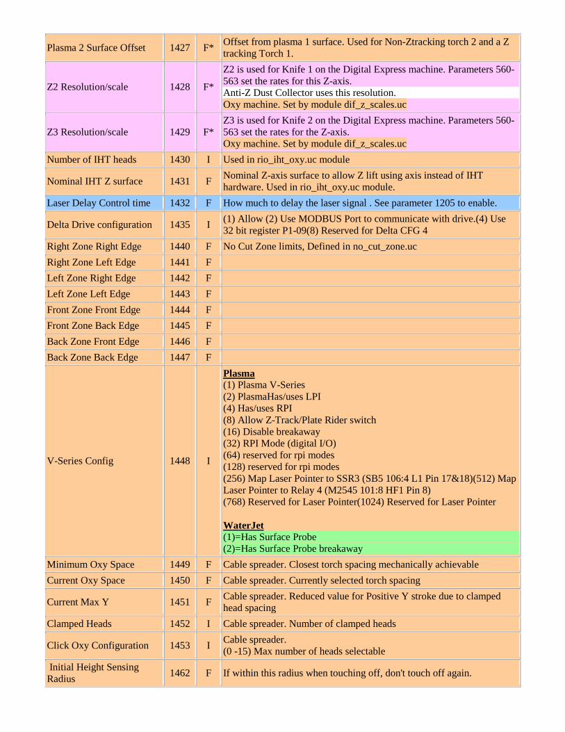
Plasma 2 Surface Offset 1427 F* Offset from plasma 1 surface. Used for Non-Ztracking torch 2 and a Z tracking Torch 1.
Z2 Resolution/scale 1428 F*
Z2 is used for Knife 1 on the Digital Express machine. Parameters 560-563 set the rates for this Z-axis. Anti-Z Dust Collector uses this resolution. Oxy machine. Set by module dif_z_scales.uc
Z3 Resolution/scale 1429 F* Z3 is used for Knife 2 on the Digital Express machine. Parameters 560-563 set the rates for the Z-axis. Oxy machine. Set by module dif_z_scales.uc
Number of IHT heads 1430 I Used in rio_iht_oxy.uc module
Nominal IHT Z surface 1431 F Nominal Z-axis surface to allow Z lift using axis instead of IHT hardware. Used in rio_iht_oxy.uc module.
Laser Delay Control time 1432 F How much to delay the laser signal . See parameter 1205 to enable.
Delta Drive configuration 1435 I (1) Allow (2) Use MODBUS Port to communicate with drive.(4) Use 32 bit register P1-09(8) Reserved for Delta CFG 4
Right Zone Right Edge 1440 F No Cut Zone limits, Defined in no_cut_zone.uc Right Zone Left Edge 1441 F Left Zone Right Edge 1442 F Left Zone Left Edge 1443 F Front Zone Front Edge 1444 F Front Zone Back Edge 1445 F Back Zone Front Edge 1446 F Back Zone Back Edge 1447 F
V-Series Config 1448 I
Plasma (1) Plasma V-Series (2) PlasmaHas/uses LPI (4) Has/uses RPI (8) Allow Z-Track/Plate Rider switch (16) Disable breakaway (32) RPI Mode (digital I/O) (64) reserved for rpi modes (128) reserved for rpi modes (256) Map Laser Pointer to SSR3 (SB5 106:4 L1 Pin 17&18)(512) Map Laser Pointer to Relay 4 (M2545 101:8 HF1 Pin 8) (768) Reserved for Laser Pointer(1024) Reserved for Laser Pointer WaterJet (1)=Has Surface Probe (2)=Has Surface Probe breakaway
Minimum Oxy Space 1449 F Cable spreader. Closest torch spacing mechanically achievable Current Oxy Space 1450 F Cable spreader. Currently selected torch spacing
Current Max Y 1451 F Cable spreader. Reduced value for Positive Y stroke due to clamped head spacing
Clamped Heads 1452 I Cable spreader. Number of clamped heads
Click Oxy Configuration 1453 I Cable spreader. (0 -15) Max number of heads selectable
Initial Height Sensing Radius 1462 F If within this radius when touching off, don't touch off again.
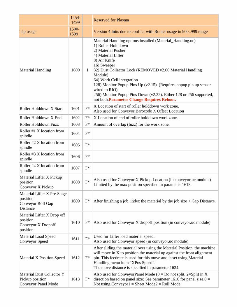
1454-1499 Reserved for Plasma
Tip usage 1500-1599 Version 4 Inits due to conflict with Router usage in 900..999 range
Material Handling 1600 I
Material Handling options installed (Material_Handling.uc) 1) Roller Holddown 2) Material Pusher 4) Material Lifter 8) Air Knife 16) Sweeper 32) Dust Collector Lock (REMOVED v2.00 Material Handling Module) 64) Work Cell integration 128) Monitor Popup Pins Up (v2.15). (Requires popup pin up sensor wired to RIO). 256) Monitor Popup Pins Down (v2.22). Either 128 or 256 supported, not both.Parameter Change Requires Reboot.
Roller Holddown X Start 1601 F* X Location of start of roller holddown work zone. Also used for Conveyor Barocode X Offset Location
Roller Holddown X End 1602 F* X Location of end of roller holddown work zone. Roller Holddown Fuzz 1603 F* Amount of overlap (fuzz) for the work zone. Roller #1 X location from spindle 1604 F*
Roller #2 X location from spindle 1605 F*
Roller #3 X location from spindle 1606 F*
Roller #4 X location from spindle 1607 F*
Material Lifter X Pickup position Conveyor X Pickup
1608 F* Also used for Conveyor X Pickup Location (in conveyor.uc module) Limited by the max position specified in parameter 1618.
Material Lifter X Pre-Stage position Conveyor Roll Gap Distance
1609 F* After finishing a job, index the material by the job size + Gap Distance.
Material Lifter X Drop off position Conveyor X Dropoff position
1610 F* Also used for Conveyor X dropoff position (in conveyor.uc module)
Material Load Speed Conveyor Speed 1611 F* Used for Lifter load material speed.
Also used for Conveyor speed (in conveyor.uc module)
Material X Position Speed 1612 F*
After sliding the material over using the Material Position, the machine will move in X to position the material up against the front alignment pin. This feedrate is used for this move and is set using Material Handling menu item “XPos Speed”. The move distance is specified in parameter 1624.
Material Dust Collector Y Pickup position Conveyor Panel Mode
1613 F* Also used for ConveyorPanel Mode (0 = Do not split, 2=Split in X direction based on panel size) See parameter 1616 for panel size.0 = Not using Conveyor1 = Sheet Mode2 = Roll Mode
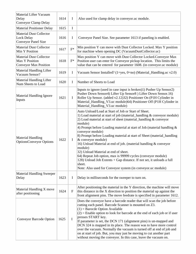
Material Lifter Vacuum Delay Conveyor Clamp Delay
1614 I Also used for clamp delay in conveyor.uc module.
Material Positioner Delay 1615 I Material Dust Collector Lock Delay Conveyor Panel Size
1616 I Conveyor Panel Size. See parameter 1613 if paneling is enabled.
Material Dust Collector Min Y Position 1617 F* Min position Y can move with Dust Collector Locked. Max Y position
for machine when opening DC (VacuumDustCollector.uc) Material Dust Collector Max Y Position Conveyor Max Position
1618 F* Max position Y can move with Dust Collector Locked.Conveyor Max Position user can enter for Conveyor pickup location. This limits the value that can be entered for parameter 1608. (in conveyor.uc module)
Material Handling Lifter Vacuum Sensor? 1619 I Vacuum Sensor Installed? (1=yes, 0=no) (Material_Handling.uc v2.0)
Material Handling Lifter Num Sheets to Load 1620 I Number of Sheets to Load
Material Handling Ignore Inputs 1621 I
Inputs to ignore (used in case input is broken)1) Pusher Up Sensor2) Pusher Down Sensor4) Lifter Up Sensor8 ) Lifter Down Sensor.16) Roller Up Sensor. (added v2.12)32) Positioner On (P1H Cylinder in Material_Handling_V3.uc module)64) Positioner Off (P1H Cylinder in Material_Handling_V3.uc module)
Material Handling OptionsConveyor Options 1622 I
Auto Unload/Load at Start of Job or Start of Sheet. 1) Load material at start of job (material_handling & conveyor module) 2) Load material at start of sheet (material_handling & conveyor module) 4) Prompt before Loading material at start of Job (material handling & conveyor module) 8) Prompt before Loading material at start of Sheet (material_handling & conveyor module) 16) Unload Material at end of job. (material handling & conveyor module) 32) Unload Material at end of sheet. 64) Repeat Job option, max is 99999 cycles (conveyor module) 128) Unload Job Extents + Gap distance. If not set, it unloads a full sheet. Note: Also used for Conveyor system (in conveyor.uc module)
Material Handling Sweeper Delay
1623 I Delay in milliseconds for the sweeper to turn on.
Material Handling X move after positioning 1624 F
After positioning the material in the Y direction, the machine will move this distance in the X direction to position the material up against the front alignment pins. The move feedrate is specified in parameter 1612.
Conveyor Barcode Option 1625 I
Does the conveyor have a barcode reader that will scan the job before cutting each panel. Barcode Scanner is mounted on Z3. (1) = Barocde Option Available (2) = Enable option to look for barcode at the end of each job or if user presses START key. If parameter is set, the DCN 171 (alignment pins) is un-mapped and DCN 324 is mapped in its place. The reason was to have more control over the vacuum. Normally the vacuum is turned off at end of job and on at start of job. But, you may just be moving to cut another part without moving the conveyor. In this case, leave the vacuum on.
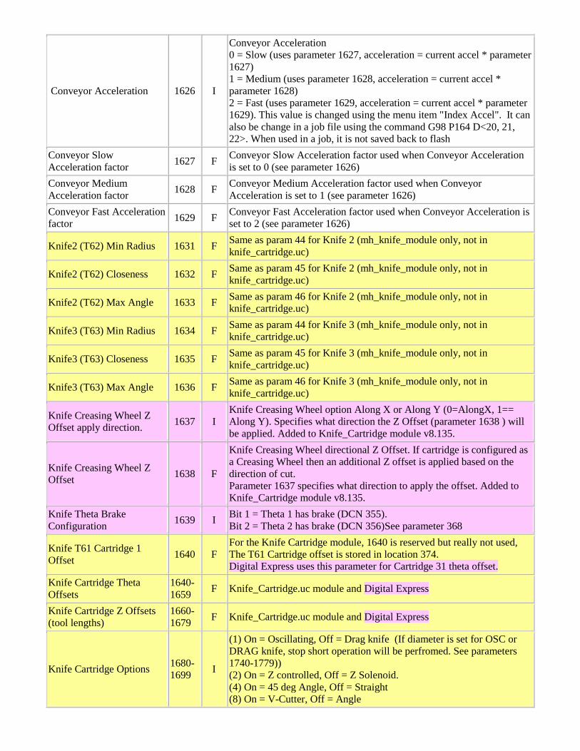
Conveyor Acceleration 1626 I
Conveyor Acceleration 0 = Slow (uses parameter 1627, acceleration = current accel * parameter 1627) 1 = Medium (uses parameter 1628, acceleration = current accel * parameter 1628) 2 = Fast (uses parameter 1629, acceleration = current accel * parameter 1629). This value is changed using the menu item "Index Accel". It can also be change in a job file using the command G98 P164 D<20, 21, 22>. When used in a job, it is not saved back to flash
Conveyor Slow Acceleration factor 1627 F Conveyor Slow Acceleration factor used when Conveyor Acceleration
is set to 0 (see parameter 1626) Conveyor Medium Acceleration factor 1628 F Conveyor Medium Acceleration factor used when Conveyor
Acceleration is set to 1 (see parameter 1626) Conveyor Fast Acceleration factor 1629 F Conveyor Fast Acceleration factor used when Conveyor Acceleration is
set to 2 (see parameter 1626)
Knife2 (T62) Min Radius 1631 F Same as param 44 for Knife 2 (mh_knife_module only, not in knife_cartridge.uc)
Knife2 (T62) Closeness 1632 F Same as param 45 for Knife 2 (mh_knife_module only, not in knife_cartridge.uc)
Knife2 (T62) Max Angle 1633 F Same as param 46 for Knife 2 (mh_knife_module only, not in knife_cartridge.uc)
Knife3 (T63) Min Radius 1634 F Same as param 44 for Knife 3 (mh_knife_module only, not in knife_cartridge.uc)
Knife3 (T63) Closeness 1635 F Same as param 45 for Knife 3 (mh_knife_module only, not in knife_cartridge.uc)
Knife3 (T63) Max Angle 1636 F Same as param 46 for Knife 3 (mh_knife_module only, not in knife_cartridge.uc)
Knife Creasing Wheel Z Offset apply direction. 1637 I
Knife Creasing Wheel option Along X or Along Y (0=AlongX, 1== Along Y). Specifies what direction the Z Offset (parameter 1638 ) will be applied. Added to Knife_Cartridge module v8.135.
Knife Creasing Wheel Z Offset 1638 F
Knife Creasing Wheel directional Z Offset. If cartridge is configured as a Creasing Wheel then an additional Z offset is applied based on the direction of cut. Parameter 1637 specifies what direction to apply the offset. Added to Knife_Cartridge module v8.135.
Knife Theta Brake Configuration 1639 I Bit 1 = Theta 1 has brake (DCN 355).
Bit 2 = Theta 2 has brake (DCN 356)See parameter 368
Knife T61 Cartridge 1 Offset 1640 F
For the Knife Cartridge module, 1640 is reserved but really not used, The T61 Cartridge offset is stored in location 374. Digital Express uses this parameter for Cartridge 31 theta offset.
Knife Cartridge Theta Offsets
1640-1659 F Knife_Cartridge.uc module and Digital Express
Knife Cartridge Z Offsets (tool lengths)
1660-1679 F Knife_Cartridge.uc module and Digital Express
Knife Cartridge Options 1680-1699 I
(1) On = Oscillating, Off = Drag knife (If diameter is set for OSC or DRAG knife, stop short operation will be perfromed. See parameters 1740-1779)) (2) On = Z controlled, Off = Z Solenoid. (4) On = 45 deg Angle, Off = Straight (8) On = V-Cutter, Off = Angle
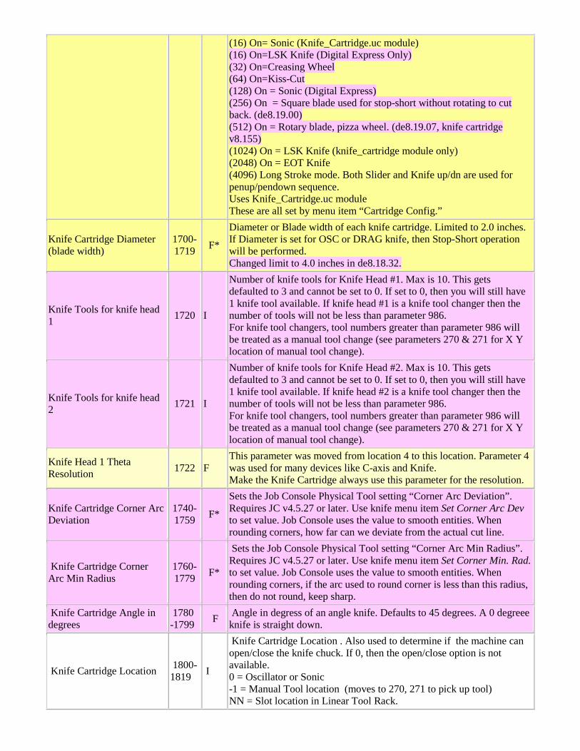
(16) On= Sonic (Knife_Cartridge.uc module) (16) On=LSK Knife (Digital Express Only) (32) On=Creasing Wheel (64) On=Kiss-Cut (128) On = Sonic (Digital Express) (256) On = Square blade used for stop-short without rotating to cut back. (de8.19.00) (512) On = Rotary blade, pizza wheel. (de8.19.07, knife cartridge v8.155) (1024) On = LSK Knife (knife_cartridge module only) (2048) On = EOT Knife (4096) Long Stroke mode. Both Slider and Knife up/dn are used for penup/pendown sequence. Uses Knife_Cartridge.uc module These are all set by menu item “Cartridge Config.”
Knife Cartridge Diameter (blade width)
1700-1719 F*
Diameter or Blade width of each knife cartridge. Limited to 2.0 inches. If Diameter is set for OSC or DRAG knife, then Stop-Short operation will be performed. Changed limit to 4.0 inches in de8.18.32.
Knife Tools for knife head 1 1720 I
Number of knife tools for Knife Head #1. Max is 10. This gets defaulted to 3 and cannot be set to 0. If set to 0, then you will still have 1 knife tool available. If knife head #1 is a knife tool changer then the number of tools will not be less than parameter 986. For knife tool changers, tool numbers greater than parameter 986 will be treated as a manual tool change (see parameters 270 & 271 for X Y location of manual tool change).
Knife Tools for knife head 2 1721 I
Number of knife tools for Knife Head #2. Max is 10. This gets defaulted to 3 and cannot be set to 0. If set to 0, then you will still have 1 knife tool available. If knife head #2 is a knife tool changer then the number of tools will not be less than parameter 986. For knife tool changers, tool numbers greater than parameter 986 will be treated as a manual tool change (see parameters 270 & 271 for X Y location of manual tool change).
Knife Head 1 Theta Resolution 1722 F
This parameter was moved from location 4 to this location. Parameter 4 was used for many devices like C-axis and Knife. Make the Knife Cartridge always use this parameter for the resolution.
Knife Cartridge Corner Arc Deviation
1740-1759 F*
Sets the Job Console Physical Tool setting “Corner Arc Deviation”. Requires JC v4.5.27 or later. Use knife menu item Set Corner Arc Dev to set value. Job Console uses the value to smooth entities. When rounding corners, how far can we deviate from the actual cut line.
Knife Cartridge Corner Arc Min Radius
1760-1779 F*
Sets the Job Console Physical Tool setting “Corner Arc Min Radius”. Requires JC v4.5.27 or later. Use knife menu item Set Corner Min. Rad. to set value. Job Console uses the value to smooth entities. When rounding corners, if the arc used to round corner is less than this radius, then do not round, keep sharp.
Knife Cartridge Angle in degrees
1780 -1799 F Angle in degress of an angle knife. Defaults to 45 degrees. A 0 degreee
knife is straight down.
Knife Cartridge Location 1800-1819 I
Knife Cartridge Location . Also used to determine if the machine can open/close the knife chuck. If 0, then the open/close option is not available. 0 = Oscillator or Sonic -1 = Manual Tool location (moves to 270, 271 to pick up tool) NN = Slot location in Linear Tool Rack.
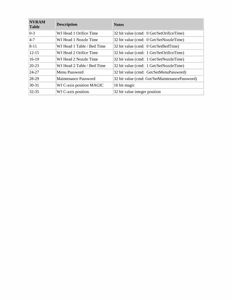
NVRAM Table Description
Notes
0-3 WJ Head 1 Orifice Time 32 bit value (cmd: 0 Get/SetOrificeTime) 4-7 WJ Head 1 Nozzle Time 32 bit value (cmd: 0 Get/SetNozzleTime) 8-11 WJ Head 1 Table / Bed Time 32 bit value (cmd: 0 Get/SetBedTime) 12-15 WJ Head 2 Orifice Time 32 bit value (cmd: 1 Get/SetOrificeTime) 16-19 WJ Head 2 Nozzle Time 32 bit value (cmd: 1 Get/SetNozzleTime) 20-23 WJ Head 2 Table / Bed Time 32 bit value (cmd: 1 Get/SetNozzleTime) 24-27 Menu Password 32 bit value (cmd: Get/SetMenuPassword) 28-29 Maintenance Password 32 bit value (cmd: Get/SetMaintenancePassword) 30-31 WJ C-axis position MAGIC 16 bit magic 32-35 WJ C-axis position. 32 bit value integer position