Embed Size (px)
Citation preview
Multimaterial Mesh-Based Surface Tracking
Fang Da⇤Columbia University
Christopher Batty†University of Waterloo
Eitan Grinspun‡
Columbia University
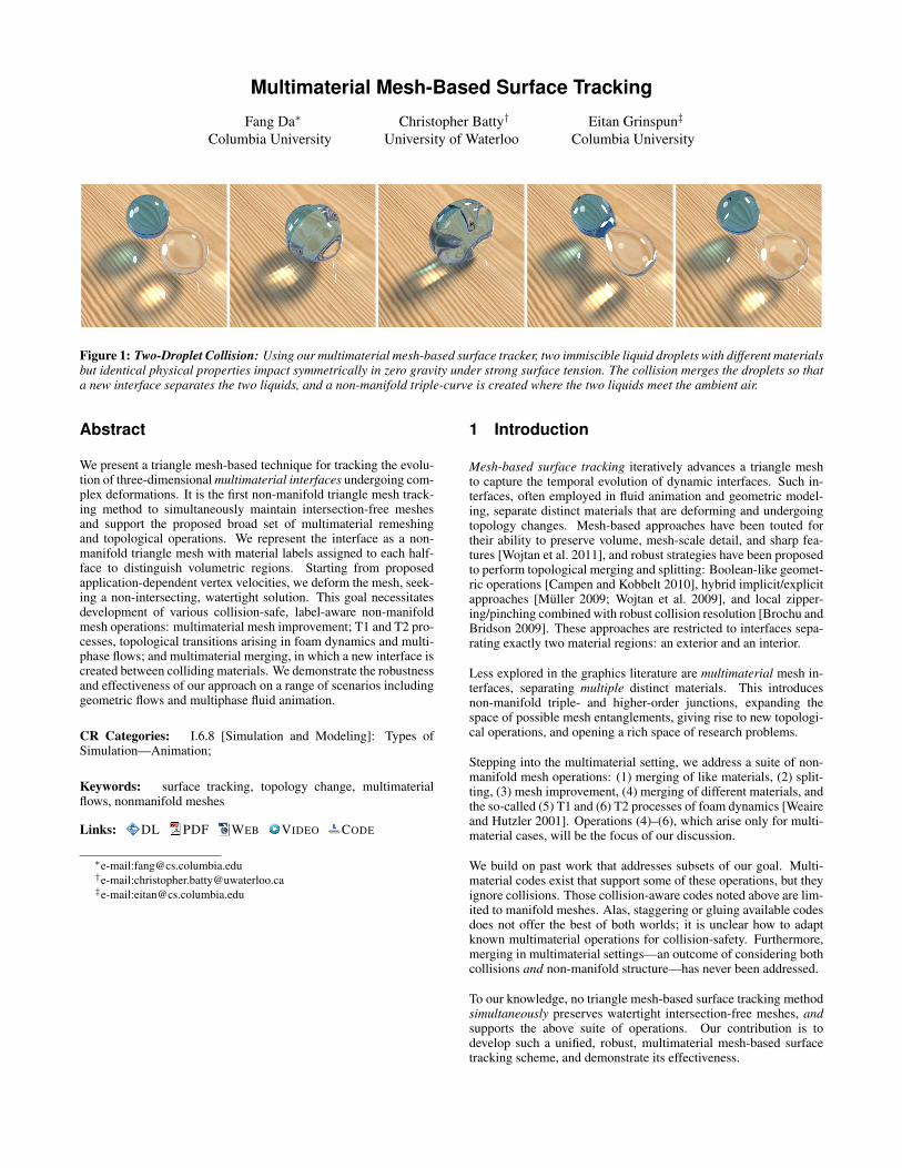
Figure 1: Two-Droplet Collision: Using our multimaterial mesh-based surface tracker, two immiscible liquid droplets with different materialsbut identical physical properties impact symmetrically in zero gravity under strong surface tension. The collision merges the droplets so thata new interface separates the two liquids, and a non-manifold triple-curve is created where the two liquids meet the ambient air.
Abstract
We present a triangle mesh-based technique for tracking the evolu-tion of three-dimensional multimaterial interfaces undergoing com-plex deformations. It is the first non-manifold triangle mesh track-ing method to simultaneously maintain intersection-free meshesand support the proposed broad set of multimaterial remeshingand topological operations. We represent the interface as a non-manifold triangle mesh with material labels assigned to each half-face to distinguish volumetric regions. Starting from proposedapplication-dependent vertex velocities, we deform the mesh, seek-ing a non-intersecting, watertight solution. This goal necessitatesdevelopment of various collision-safe, label-aware non-manifoldmesh operations: multimaterial mesh improvement; T1 and T2 pro-cesses, topological transitions arising in foam dynamics and multi-phase flows; and multimaterial merging, in which a new interface iscreated between colliding materials. We demonstrate the robustnessand effectiveness of our approach on a range of scenarios includinggeometric flows and multiphase fluid animation.
CR Categories: I.6.8 [Simulation and Modeling]: Types ofSimulation—Animation;
Keywords: surface tracking, topology change, multimaterialflows, nonmanifold meshes
Links: DL PDF WEB VIDEO CODE
⇤e-mail:[email protected]†e-mail:[email protected]‡e-mail:[email protected]
1 Introduction
Mesh-based surface tracking iteratively advances a triangle meshto capture the temporal evolution of dynamic interfaces. Such in-terfaces, often employed in fluid animation and geometric model-ing, separate distinct materials that are deforming and undergoingtopology changes. Mesh-based approaches have been touted fortheir ability to preserve volume, mesh-scale detail, and sharp fea-tures [Wojtan et al. 2011], and robust strategies have been proposedto perform topological merging and splitting: Boolean-like geomet-ric operations [Campen and Kobbelt 2010], hybrid implicit/explicitapproaches [Muller 2009; Wojtan et al. 2009], and local zipper-ing/pinching combined with robust collision resolution [Brochu andBridson 2009]. These approaches are restricted to interfaces sepa-rating exactly two material regions: an exterior and an interior.
Less explored in the graphics literature are multimaterial mesh in-terfaces, separating multiple distinct materials. This introducesnon-manifold triple- and higher-order junctions, expanding thespace of possible mesh entanglements, giving rise to new topologi-cal operations, and opening a rich space of research problems.
Stepping into the multimaterial setting, we address a suite of non-manifold mesh operations: (1) merging of like materials, (2) split-ting, (3) mesh improvement, (4) merging of different materials, andthe so-called (5) T1 and (6) T2 processes of foam dynamics [Weaireand Hutzler 2001]. Operations (4)–(6), which arise only for multi-material cases, will be the focus of our discussion.
We build on past work that addresses subsets of our goal. Multi-material codes exist that support some of these operations, but theyignore collisions. Those collision-aware codes noted above are lim-ited to manifold meshes. Alas, staggering or gluing available codesdoes not offer the best of both worlds; it is unclear how to adaptknown multimaterial operations for collision-safety. Furthermore,merging in multimaterial settings—an outcome of considering bothcollisions and non-manifold structure—has never been addressed.
To our knowledge, no triangle mesh-based surface tracking methodsimultaneously preserves watertight intersection-free meshes, andsupports the above suite of operations. Our contribution is todevelop such a unified, robust, multimaterial mesh-based surfacetracking scheme, and demonstrate its effectiveness.
2 Related Work
2.1 Multimaterial Surface Tracking Methods
Level set methods [Sethian 1999; Osher and Fedkiw 2002] areusually extended to multimaterial settings by replacing the binarysign of the distance field with an integer material label [Losassoet al. 2006; Zheng et al. 2006; Kim 2010; Saye and Sethian 2012].In some methods one signed distance field is used per region,while other methods reduce storage and computational costs byusing a single unsigned distance field for all regions. Starinshaket al. [2014] discuss one challenge specific to multimaterial levelset methods—overlaps or vacuums at the triple junctions—whichis typically corrected via projection. By contrast, our non-manifoldmesh-based approach explicitly tracks such triple-junctions, avoid-ing vacuums/overlaps by construction. Previous work in mesh-based surface tracking has explored trade-offs between explicit andimplicit approaches in the standard two-material setting (e.g., [Duet al. 2006; Wojtan et al. 2009]).
Particle-based surface representations augment each particlewith a material label or color [Muller et al. 2005; Solenthaler andPajarola 2008], or assign material properties to particles directly.
Volume-of-fluid methods [Hirt and Nichols 1981] store a volumefraction per cell, and their multimaterial generalizations store apartition of unity (one fraction per material); various approachesexist to reconstruct continuous interface geometry from this data[Dyadechko and Shashkov 2008; Anderson et al. 2010].
Moving mesh or Lagrangian volumetric mesh methods [Quanand Schmidt 2007; Pons and Boissonnat 2007a; Pons and Boisson-nat 2007b; Quan et al. 2009; Misztal et al. 2012] assign materiallabels to each volume element. For example, for a tetrahedraliza-tion of space, the interface is the subset of triangular faces border-ing two differently labeled tetrahedra. Several recent works addressmesh quality maintenance [Wicke et al. 2010; Clausen et al. 2013].
2.2 Triangle Meshes with Merging and Splitting
Mesh Surgery / Boolean Approaches. Topology changes are rec-ognized as a challenge for surface mesh evolution, or “front track-ing” [Glimm et al. 1998; Glimm et al. 2000]. Colliding surfaces en-tangle and must be stitched via mesh surgery or Boolean(-like) op-erations [Campen and Kobbelt 2010; Zaharescu et al. 2011; Bern-stein and Wojtan 2013]. Existing two-phase solutions do not mapdirectly to the multimaterial setting, where new topological changesarise. For instance, the collision of two different materials im-mersed in a third requires that a separating interface be established;this interface is not a component of any existing surface. Bern-stein and Wojtan [2013] specifically highlight this limitation of theirmethod, noting that a broader set of fundamentally different topo-logical operations may be required for some applications.
Hybrid Implicit Approaches sidestep the requisite mesh opera-tions by converting colliding regions into implicit (e.g., Eulerian)representations, either globally or locally, and then reconstructing(e.g., via marching cubes) a new mesh [Glimm et al. 2000; Du et al.2006; Bargteil et al. 2006; Muller 2009; Wojtan et al. 2009; Wo-jtan et al. 2010]. In computational physics the best known is theFronTier package [Du et al. 2006]. These methods rely on a binaryinside/outside classification, and a multimaterial extension appearsnontrivial.
Proximity-Based Merging locally stitches proximate meshes,maintaining an intersection-free invariant via either conservativebounds on time step [Stanculescu et al. 2011] or robust post-collision processing [Brochu and Bridson 2009]. The reliance on
a kernel of simple, local mesh operations led us to extend this lineof work to multiple materials, building on El Topo [Brochu andBridson 2009].
2.3 Triangle Mesh-Based Multimaterial Techniques
Surface Evolver [Brakke 1992], a popular software package, isa great source of inspiration for our work. The package uses anevolving non-manifold triangle mesh to find equilibria for myriadvariational problems. It supports the foam and film-like topologicaltransformations arising in many multimaterial settings, known asT1 and T2 processes (§4.4). We differ principally in (1) consider-ing collisions, which induce new merging-type topology changes,and (2) ensuring intersection-safety throughout, which is difficultwhen topological transitions have special cases or affect large meshneighborhoods. We develop a new approach for T1 processes (§5)that avoids special cases and, crucially, iteratively applies only asingle local vertex operation.
Surface Evolver and related approaches have been applied to foamcoarsening and grain growth problems in material sciences, forwhich collisions are often unimportant [Weygand and Brechet1999; Wakai et al. 2000; Kuprat et al. 2003; Mora et al. 2008; Syhaand Weygand 2010]. Most recently, Lazar et al. [2011] consideredlarge-scale simulations of up to 100,000 distinct grains. Authors ingraphics have also studied constant mean curvature surfaces usingrelated techniques [Pan et al. 2012]. In general, these methods donot consider collision-induced merging or intersection-safety, andapply topological operations with larger mesh stencils.
3 Multimaterial Mesh Representation
Two-material mesh-based methods rely on a binary inside/outsideclassification of space. This classification may employ parity count-ing of ray casts, which does not readily extend to multiple materials;alternatively, it may employ a consistent orientation of mesh trian-gles: each triangle’s vertex ordering and the right-hand rule define anormal direction, which by convention points to the interior. If eachtriangle is oriented consistently with its neighbors, and the mesh iswatertight and non-self-intersecting, we have a strict binary classi-fication that enables safe topological operations.
The non-manifold setting requires n-ary materialclassification, so mesh normals do not suffice. In-stead, we follow previous authors [Brakke 1992;Yuan et al. 2012] in giving each material a unique in-teger label, and applying labels to the front and backof each triangle (i.e., each half-face is labeled). Inthis analogous 2D polygon example, colors indicatelabels. The top image shows the represented mate-rial regions (including the “exterior” orange region),while the bottom image shows the correspondingmesh where edges each have two labels. This rep-resentation does not require consistent triangle ori-entation, even for triangle-pairs sharing a manifoldedge. Instead, it requires consistent material labels: all half-facesbounding a closed region must be labeled identically. Maintainingand exploiting this extended notion of mesh orientation allows usto preserve watertight regions.
Throughout, the term region refers to a closed volume of space,while material refers to a region’s type, indicated by its labels.Thus, two regions may be composed of the same material, but aregion cannot consist of more than one material.
4 Method Overview
Beginning from an initially valid and non-self-intersecting multi-material mesh, our overall approach proceeds as follows. The clientapplication proposes a set of vertex trajectories, which we processwith collision resolution techniques to recover an intersection-freestate. We then perform merging, mesh improvement, and splitting,ensuring that each operation maintains intersection-safety. Algo-rithm 1 lays out the structure of our method.
Algorithm 1 Multimaterial Mesh-Based Surface Tracking
Note: mesh is intersection-free after each checkmark (X)while simulating do
Advance vertices to predicted positions (§4.1)Resolve interpenetrations (§4.2) XPerform topological merging (§7) XPerform mesh improvement (§4.3) XPerform topological separation (§5 and §6) X
end while
4.1 Computing Vertex Positions
We first ask the domain-application to advance the mesh verticesto their proposed positions. A typical application will respond bytime-integrating a physical equation or geometric flow, but ulti-mately we are agnostic to the source of the motion. The proposedtrajectory may induce mesh intersections.
4.2 Resolving Interpenetrations
Next, we perturb the proposed trajectory to a non-intersecting state.We apply exact continuous collision detection (CCD) [Brochu et al.2012], and resolve collisions using the method of Bridson et al.[2002] as extended by Harmon et al. [2008]. Our enforcement ofan intersection-free invariant is crucial: subsequent steps rely on itto ensure that remeshing and topology changes are performed safelyand successfully, following the general strategy of Brochu and Brid-son [2009]. Beginning from the intersection-free state produced bycollision-resolution, every proposed edit to the mesh is checked forcollisions and canceled if any would be introduced. That is, in-dividual mesh edits are treated as atomic operations that eithercomplete in full or are canceled; at all other times the mesh isintersection-free. Treating mesh edits atomically also implies thatwe should prefer fine-grained local edits, since these can be morecheaply collision-checked and succeed more often in the presenceof tangled geometries.
4.3 Mesh Improvement
Strong mesh deformations necessitate remeshing to maintain tri-angle sizes and aspect ratios. We apply an incremental, feature-preserving scheme based on that of Brochu and Bridson [2009],which is collision-safe per the discussion above. Complete details,including extensions for non-manifoldness and multimaterial label-ing, are in the supplemental material.
4.4 Multimaterial Topology Changes
Multimaterial scenarios in 3D undergo new topological transitionsthat do not arise with only two materials. We first discuss the 2Danalogs to provide intuition (Figure 2).
Multimaterial Merging, discussed in §7, occurs when two distinctmaterial regions collide while immersed in a third; the middle re-gion divides in two, and a new interface maintains separation be-tween the originally disjoint outer regions (Figure 2, top). This
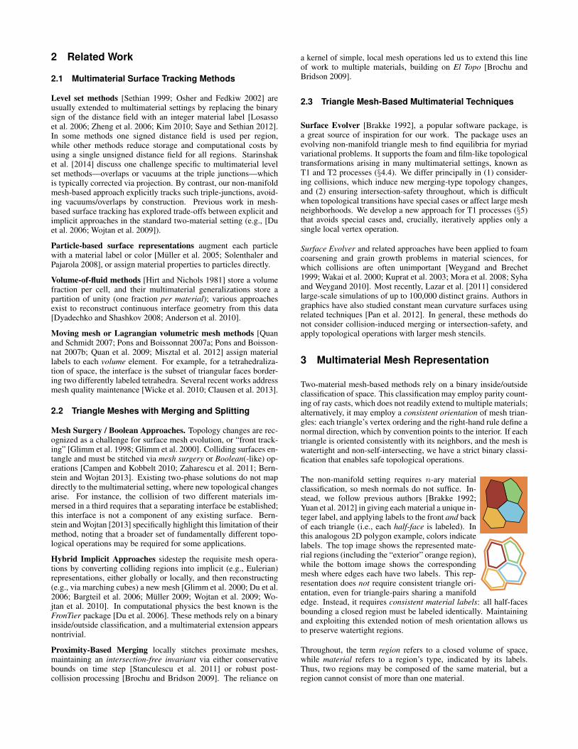
Figure 2: Multimaterial topology changes in 2D. Merging (top):Two material regions separated by a third collide to yield a sharedinterface. T1 process (middle): Two regions that share a borderseparate while the remaining pair become connected. T2 pro-cess (bottom): One region (cyan) collapses away.
contrasts with the usual two-material case, where colliding regionsalways have the same material, and merge into one.
T1 and T2 Processes are known from the literature on soap filmsand bubbles [Weaire and Hutzler 2001], and can describe how airbubbles (i.e., materials) within a connected soap foam can changetheir local connectivity under flow. In a T1 process two materi-als that originally share a border separate from one another whiletwo different neighbouring materials become connected (Figure 2,middle). This forms a new interface while leaving the region countunchanged, and can only occur with four or more materials. In aT2 process a region collapses to a point and disappears as occurscommonly in convergent flows (Figure 2, bottom).
5 T1 Processes
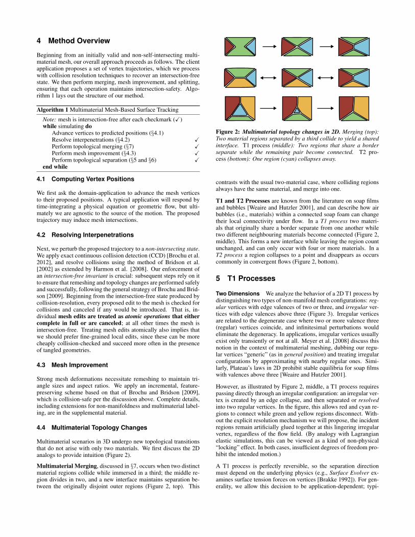
Two Dimensions We analyze the behavior of a 2D T1 process bydistinguishing two types of non-manifold mesh configurations: reg-ular vertices with edge valences of two or three, and irregular ver-tices with edge valences above three (Figure 3). Irregular verticesare related to the degenerate case where two or more valence three(regular) vertices coincide, and infinitesimal perturbations wouldeliminate the degeneracy. In applications, irregular vertices usuallyexist only transiently or not at all. Meyer et al. [2008] discuss thisnotion in the context of multimaterial meshing, dubbing our regu-lar vertices “generic” (as in general position) and treating irregularconfigurations by approximating with nearby regular ones. Simi-larly, Plateau’s laws in 2D prohibit stable equilibria for soap filmswith valences above three [Weaire and Hutzler 2001].
However, as illustrated by Figure 2, middle, a T1 process requirespassing directly through an irregular configuration: an irregular ver-tex is created by an edge collapse, and then separated or resolvedinto two regular vertices. In the figure, this allows red and cyan re-gions to connect while green and yellow regions disconnect. With-out the explicit resolution mechanism we will propose, the incidentregions remain artificially glued together at this lingering irregularvertex, regardless of the flow field. (By analogy with Lagrangianelastic simulations, this can be viewed as a kind of non-physical“locking” effect. In both cases, insufficient degrees of freedom pro-hibit the intended motion.)
A T1 process is perfectly reversible, so the separation directionmust depend on the underlying physics (e.g., Surface Evolver ex-amines surface tension forces on vertices [Brakke 1992]). For gen-erality, we allow this decision to be application-dependent; typi-
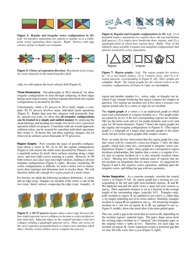
Figure 3: Regular and irregular vertex configurations in 2D:
Left: An interface separating two regions is regular, as is a triple-point vertex separating three regions. Right: Vertices with edgevalence of four or higher are irregular.
Figure 4: Choice of separation direction: Resolution of an irregu-lar vertex depends on the underlying flow field.
cally, we will analyze the local velocity field (Figure 4).
Three Dimensions Our philosophy in 3D is identical: we allowirregular configurations to arise through collapsing of short edgesduring mesh improvement, and then separate them back into regularconfigurations as dictated by the flow.
Unfortunately, while a T1 process in 2D is fairly simple, a com-plete 3D T1 process involves many individual mesh operations(Figure 5). Rather than treat this situation with potentially frag-ile, special-case code, we show that all irregular configurationscan be treated in a simple and unified manner by analyzing themesh topology and iterating on a single, low-level vertex separationoperation which we propose. Consistent with our overall approach,collision-safety can be assured by canceling individual operationsthat violate it. In theory this can delay topology changes, but weobserved no artifacts across thousands of T1 processes.
Region Graphs Now consider the space of possible configura-tions about a vertex in 3D. As in 2D, the regular configurations(Figure 6, left) mirror the stable states described by Plateau’s laws:a manifold surface by itself; three surfaces meeting along a triplecurve; and four triple curves meeting at a point. However, in 3Dboth vertices and edges may have high valences, leading to diverseirregular configurations (Figure 6, right). Because visualizing 3Dvertex configurations is difficult, we need a better tool to charac-terize their topology and determine how to resolve them. We willtherefore define the concept of a region graph of a mesh vertex.
For brevity, we adopt the following incidence definitions. A vertexand an edge (resp. triangle) are incident if the vertex is one of thetwo (resp. three) vertices composing the edge (resp. triangle). A
Figure 5: A 3D T1 process begins when a short edge between dis-tinct triple-junction curves collapses to become a vertex incident onfour materials. Adjacent edges on the original interface (red) alsocollapse yielding a quadruple-junction curve. Then, one vertex onthe curve separates perpendicularly to create a new interface (darkblue). Nearby vertices follow suit to complete the process.
Figure 6: Regular and irregular configurations in 3D: Left: (1) Amanifold surface separating two regions (here, the top and bottomhalf-spaces), (2) a triple-curve bordering three regions, and (3) aquadruple-point at which four regions meet. Right: Four of theinfinitely many possible irregular non-manifold configurations thatmust be resolved by vertex separation.
Regular Irregular
Figure 7: Region graphs: Left: The region graphs for verticesat: (1) a two-region surface, (2) a 3-region curve, and (3) a 4-region junction, corresponding to Figure 6, left. Their graphs arecomplete. Right: The region graphs for the central vertices in theirregular configurations of Figure 6, right, are incomplete.
region and another simplex (i.e., vertex, edge, or triangle) are in-cident if any triangle bordering that region contains the simplex inquestion. Two regions are incident only if they share a triangle; tworegions joined only by a vertex or edge are not incident.
The region graph of a vertex v is an undirected graph in whicheach node corresponds to a region incident on v. Two graph nodesare joined by an arc if the two corresponding regions are incident.(We use the terms node and arc for graph elements, and vertex andedge for 3D mesh elements). Figure 7 shows the region graphs forthe regular and irregular configurations in Figures 6. (This regiongraph is a subgraph of a larger dual (pseudo-)graph of the entiremesh, but per-vertex region graphs offer simpler visuals.)
Next, we make the key observation that the region graph for a reg-ular vertex will be completely connected (Figure 7, left); all othergraphs, which lack some arcs, correspond to irregular vertex con-figurations (Figure 7, right). Since graph arcs correspond to regionincidence relationships, this implies that a vertex v is regular if ev-ery pair of regions incident on v is also mutually incident (sharea face). Missing arcs therefore indicate pairs of regions that arenot incident, an irregularity that we must correct. As suggested byFigures 8 and 9, this requires vertex separation: splitting apart theirregular vertex, and filling the gap with new geometry.
Vertex Separation As a concrete example, consider the centralvertex v in Figure 9, left. Its region graph has a missing arc cor-responding to the left and right (non-incident) regions, A and B.We duplicate and pull the mesh vertex v apart into new vertices vaand vb. Their separation distance is set to a fraction of the averagelength of the surrounding edges, typically 10%. Triangles origi-nally incident to region A are updated to use vertex va rather thanv, by simply relabeling one of its vertex indices. Similarly, trianglesincident to region B are updated to use vb. All remaining trianglesincident on v, but not on region A or B, are updated to use vb.Figure 9, middle, shows the mesh after it has been pulled apart.
This may yield a gap in the mesh that we need to fill, depending onthe incident regions’ material types. The gap’s shape arises fromthe existing edges incident on v “opening” into triangular gaps, asthe original vertex v splits in two. Therefore, for each edge vwincident on region A, vertex separation creates a potential gap thatwe may fill with a new face vavbw (Figure 9, right).
v va vb va vb
v vbva
Mesh(Primal)
Region Graph(Dual)
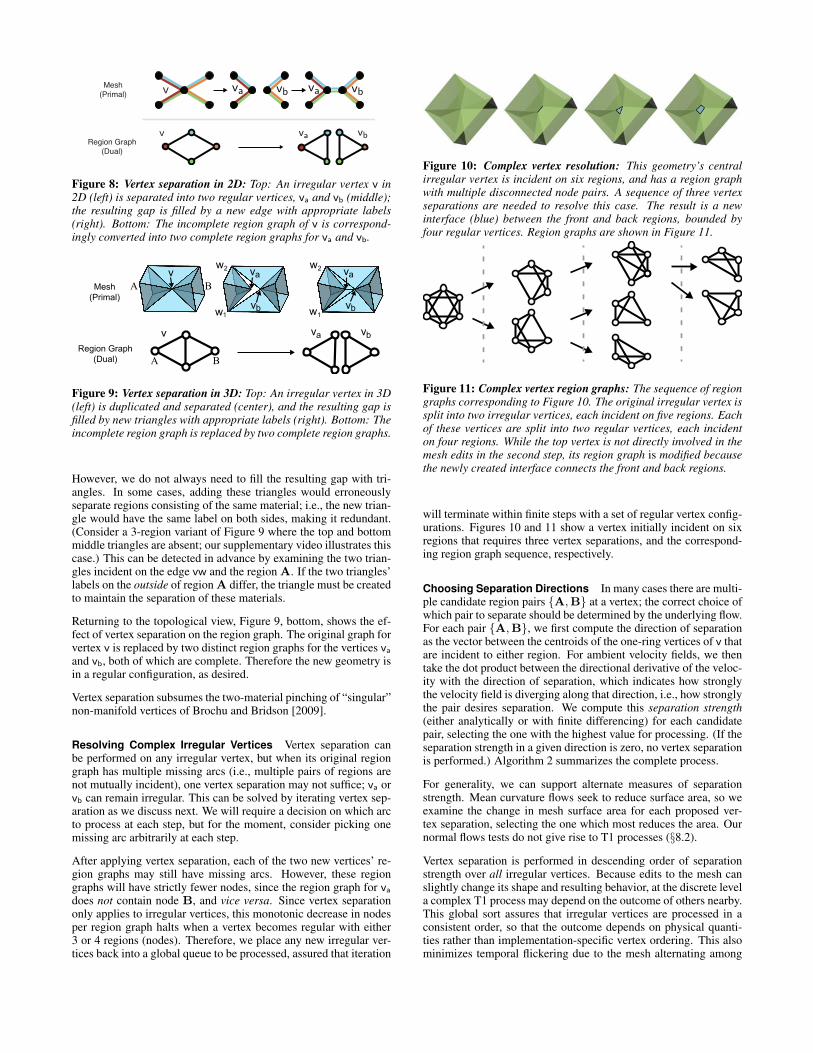
Figure 8: Vertex separation in 2D: Top: An irregular vertex v in2D (left) is separated into two regular vertices, va and vb (middle);the resulting gap is filled by a new edge with appropriate labels(right). Bottom: The incomplete region graph of v is correspond-ingly converted into two complete region graphs for va and vb.
v
vb
va
vb1
w2
w1
w2
va vbv
Mesh (Primal)
Region Graph (Dual)
w
vaA B
A B
Figure 9: Vertex separation in 3D: Top: An irregular vertex in 3D(left) is duplicated and separated (center), and the resulting gap isfilled by new triangles with appropriate labels (right). Bottom: Theincomplete region graph is replaced by two complete region graphs.
However, we do not always need to fill the resulting gap with tri-angles. In some cases, adding these triangles would erroneouslyseparate regions consisting of the same material; i.e., the new trian-gle would have the same label on both sides, making it redundant.(Consider a 3-region variant of Figure 9 where the top and bottommiddle triangles are absent; our supplementary video illustrates thiscase.) This can be detected in advance by examining the two trian-gles incident on the edge vw and the region A. If the two triangles’labels on the outside of region A differ, the triangle must be createdto maintain the separation of these materials.
Returning to the topological view, Figure 9, bottom, shows the ef-fect of vertex separation on the region graph. The original graph forvertex v is replaced by two distinct region graphs for the vertices vaand vb, both of which are complete. Therefore the new geometry isin a regular configuration, as desired.
Vertex separation subsumes the two-material pinching of “singular”non-manifold vertices of Brochu and Bridson [2009].
Resolving Complex Irregular Vertices Vertex separation canbe performed on any irregular vertex, but when its original regiongraph has multiple missing arcs (i.e., multiple pairs of regions arenot mutually incident), one vertex separation may not suffice; va orvb can remain irregular. This can be solved by iterating vertex sep-aration as we discuss next. We will require a decision on which arcto process at each step, but for the moment, consider picking onemissing arc arbitrarily at each step.
After applying vertex separation, each of the two new vertices’ re-gion graphs may still have missing arcs. However, these regiongraphs will have strictly fewer nodes, since the region graph for vadoes not contain node B, and vice versa. Since vertex separationonly applies to irregular vertices, this monotonic decrease in nodesper region graph halts when a vertex becomes regular with either3 or 4 regions (nodes). Therefore, we place any new irregular ver-tices back into a global queue to be processed, assured that iteration
Figure 10: Complex vertex resolution: This geometry’s centralirregular vertex is incident on six regions, and has a region graphwith multiple disconnected node pairs. A sequence of three vertexseparations are needed to resolve this case. The result is a newinterface (blue) between the front and back regions, bounded byfour regular vertices. Region graphs are shown in Figure 11.
Figure 11: Complex vertex region graphs: The sequence of regiongraphs corresponding to Figure 10. The original irregular vertex issplit into two irregular vertices, each incident on five regions. Eachof these vertices are split into two regular vertices, each incidenton four regions. While the top vertex is not directly involved in themesh edits in the second step, its region graph is modified becausethe newly created interface connects the front and back regions.
will terminate within finite steps with a set of regular vertex config-urations. Figures 10 and 11 show a vertex initially incident on sixregions that requires three vertex separations, and the correspond-ing region graph sequence, respectively.
Choosing Separation Directions In many cases there are multi-ple candidate region pairs {A,B} at a vertex; the correct choice ofwhich pair to separate should be determined by the underlying flow.For each pair {A,B}, we first compute the direction of separationas the vector between the centroids of the one-ring vertices of v thatare incident to either region. For ambient velocity fields, we thentake the dot product between the directional derivative of the veloc-ity with the direction of separation, which indicates how stronglythe velocity field is diverging along that direction, i.e., how stronglythe pair desires separation. We compute this separation strength(either analytically or with finite differencing) for each candidatepair, selecting the one with the highest value for processing. (If theseparation strength in a given direction is zero, no vertex separationis performed.) Algorithm 2 summarizes the complete process.
For generality, we can support alternate measures of separationstrength. Mean curvature flows seek to reduce surface area, so weexamine the change in mesh surface area for each proposed ver-tex separation, selecting the one which most reduces the area. Ournormal flows tests do not give rise to T1 processes (§8.2).
Vertex separation is performed in descending order of separationstrength over all irregular vertices. Because edits to the mesh canslightly change its shape and resulting behavior, at the discrete levela complex T1 process may depend on the outcome of others nearby.This global sort assures that irregular vertices are processed in aconsistent order, so that the outcome depends on physical quanti-ties rather than implementation-specific vertex ordering. This alsominimizes temporal flickering due to the mesh alternating among

Algorithm 2 Vertex Separation
while T1 process has occurred in the last iteration doCandidate list C = { }
for all vertex v in the mesh doConstruct v’s region graph G = V,EIf the graph G is already complete, skip this vertexfor all {A,B} /2 E where A 2 V,B 2 V do
Compute separation direction dAB
tAB separation strength(dAB)if tAB > 0 then
Add {A,B, tAB ,dAB} into the candidate list Cend if
end forend forSort C with descending t (separation strength)for all candidate {A,B, tAB ,dAB} in C do
tAB separation strength(dAB)If tAB < 0, skip this candidateCreate vertices va and vbva v + ✏dAB
vb v � ✏dAB
for all face f incident to v doif f is incident to region A then
Change f ’s vertex v to va, keeping its labelselse
Change f ’s vertex v to vb, keeping its labelsend if
end forfor all vertex w adjacent to v and incident to A do
Add face vavbw with proper labels if neededend for
end forend while
nearby configurations. While more costly than greedily separatingin the optimal direction for each vertex individually, irregular ver-tices typically comprise a small and sparse subset of the mesh.
Consistency with Edge Collapses Since edge collapse and ver-tex separation are essentially dual operations, their triggering crite-ria should be consistent. Otherwise, the same irregular vertex maybe repeatedly created and destroyed causing temporal coherence is-sues. Therefore, when performing a collapse of a short edge thatwould create an irregular vertex, we also check if the velocity fieldis acting to decrease the edge length. If not, this indicates that thephysics is driving the geometry away from the potential T1 process,so the instigating edge collapse is cancelled.
Collision-Safety It remains to ensure collision-safety of vertexseparation. To do so, we exploit the concept of pseudo-motions[Brochu and Bridson 2009], which approximates certain instanta-neous mesh operations as a continuous deformation over a step offictitious time. This allows CCD checks to identify any collisionsbetween the relevant geometry and the rest of the mesh. Vertex sep-aration can be viewed as a pseudo-motion transporting vertex v tothe position of vb, followed by a second pseudo-motion that sepa-rates va from vb, bringing the triangles of region A along with it.The newly created gap-filling triangles vavbw are just the sweepingtrajectories of the edges vbw due to the motion from vb to va.
In addition to colliding with the rest of the mesh, triangles andedges moved in the second pseudo-motion can end up intersectingthe geometry they were pulled apart from. This cannot be testedvia CCD since these elements are initially incident to vertex v, i.e.,
Figure 12: In a 3D T2 process, one region (blue) collapses away.
trivially colliding. We instead detect such intersections through in-stantaneous (static) collision detection on the final configuration.Specifically, the final positions of triangles incident on region Aare tested against all mesh edges, and the final positions of edgesincident on A are tested against all mesh triangles. This will guar-antee no intersections, but could potentially allow tunneling of verysmall components. We rule this out by testing for instantaneouscollisions between all mesh vertices and the volume swept out byeach moving triangle’s pseudo-motion. Since only a single vertexof each triangle moves during the pseudo-motion, these volumesare tetrahedra, and a standard point-in-tetrahedron test suffices.
Ordering of Operations In Algorithm 1, we perform mergingand mesh improvement before vertex separation. This choice en-sures that potential T1 processes initiated by edge collapses are usu-ally completed by vertex separation operations before proceeding tothe next time step. This allows the underlying physics to continueevolving without locking four or more regions together.
6 T2 Processes
We now consider the simpler T2 process in which a region shrinksuntil it disappears, as occurs in convergent velocity fields (Fig-ure 12). In the discrete case, a closed tetrahedron shaped regionmay undergo an edge collapse or edge flip during remeshing thatyields a specific degenerate configuration: a pair of triangles shar-ing the same three vertices. Their labels nevertheless remain con-sistent; i.e., the conceptual zero-volume region “between” the twotriangles is closed and consistently labeled.
To resolve this degeneracy, we detect if theouter regions of the two triangles have dif-ferent material labels; if so, we delete one ofthe two triangles and relabel the other, effec-tively removing the degenerate region whileleaving in place a separating interface be-tween materials (top). Otherwise, the outerregions have the same material and shouldbe connected, so we simply delete both trian-gles (bottom). The latter subsumes the two-material analog described by Brochu and Bridson [2009].
Degeneracy removal also provides a second natural splitting mech-anism. If thread-like geometry becomes very slender its tetrahedracollapse and are removed, without the explicit detection or cuttingof spindles (e.g., [Wojtan et al. 2010]).
7 Multimaterial Merging
T1 and T2 processes involve regions that are locally connected bythe non-manifold mesh. Multimaterial surface tracking also re-quires the ability to handle collision-induced topology changes be-tween regions that are initially disjoint, either merging them intoone or establishing a new separating interface. Like previous au-thors [Brochu and Bridson 2009; Stanculescu et al. 2011], we initi-
ate merging when geometry comes within a user-defined proximitythreshold. However, these existing two-phase approaches dependon a local zippering operation. While we adapted zippering to mul-tiple materials (detailed in the supplemental material), in practiceit requires well-aligned geometry to avoid causing intersections.Hence many zippering operations are canceled, preventing merg-ing and causing lingering interface noise (cf. [Brochu et al. 2010]).
7.1 Snap-Based Merging
We propose a new merging strategy based on snap-ping together of nearby vertices. Our snapping oper-ation is identical to an edge collapse, which coalescestwo existing vertices, except that the original verticesdo not share an edge. This simple operation can leadto more effective merging.
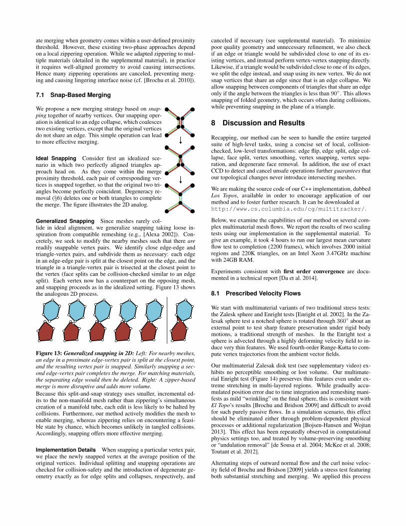
Ideal Snapping Consider first an idealized sce-nario in which two perfectly aligned triangles ap-proach head on. As they come within the mergeproximity threshold, each pair of corresponding ver-tices is snapped together, so that the original two tri-angles become perfectly coincident. Degeneracy re-moval (§6) deletes one or both triangles to completethe merge. The figure illustrates the 2D analog.
Generalized Snapping Since meshes rarely col-lide in ideal alignment, we generalize snapping taking loose in-spiration from compatible remeshing (e.g., [Alexa 2002]). Con-cretely, we seek to modify the nearby meshes such that there arereadily snappable vertex pairs. We identify close edge-edge andtriangle-vertex pairs, and subdivide them as necessary: each edgein an edge-edge pair is split at the closest point on the edge, and thetriangle in a triangle-vertex pair is trisected at the closest point tothe vertex (face splits can be collision-checked similar to an edgesplit). Each vertex now has a counterpart on the opposing mesh,and snapping proceeds as in the idealized setting. Figure 13 showsthe analogous 2D process.
Figure 13: Generalized snapping in 2D: Left: For nearby meshes,an edge in a proximate edge-vertex pair is split at the closest point,and the resulting vertex pair is snapped. Similarly snapping a sec-ond edge-vertex pair completes the merge. For matching materials,the separating edge would then be deleted. Right: A zipper-basedmerge is more disruptive and adds more volume.Because this split-and-snap strategy uses smaller, incremental ed-its to the non-manifold mesh rather than zippering’s simultaneouscreation of a manifold tube, each edit is less likely to be halted bycollisions. Furthermore, our method actively modifies the mesh toenable merging, whereas zippering relies on encountering a feasi-ble state by chance, which becomes unlikely in tangled collisions.Accordingly, snapping offers more effective merging.
Implementation Details When snapping a particular vertex pair,we place the newly snapped vertex at the average position of theoriginal vertices. Individual splitting and snapping operations arechecked for collision-safety and the introduction of degenerate ge-ometry exactly as for edge splits and collapses, respectively, and
canceled if necessary (see supplemental material). To minimizepoor quality geometry and unnecessary refinement, we also checkif an edge or triangle would be subdivided close to one of its ex-isting vertices, and instead perform vertex-vertex snapping directly.Likewise, if a triangle would be subdivided close to one of its edges,we split the edge instead, and snap using its new vertex. We do notsnap vertices that share an edge since that is an edge collapse. Weallow snapping between components of triangles that share an edgeonly if the angle between the triangles is less than 90�. This allowssnapping of folded geometry, which occurs often during collisions,while preventing snapping in the plane of a triangle.
8 Discussion and Results
Recapping, our method can be seen to handle the entire targetedsuite of high-level tasks, using a concise set of local, collision-checked, low-level transformations: edge flip, edge split, edge col-lapse, face split, vertex smoothing, vertex snapping, vertex sepa-ration, and degenerate face removal. In addition, the use of exactCCD to detect and cancel unsafe operations further guarantees thatour topological changes never introduce intersecting meshes.
We are making the source code of our C++ implementation, dubbedLos Topos, available in order to encourage application of ourmethod and to foster further research. It can be downloaded athttp://www.cs.columbia.edu/cg/multitracker/.
Below, we examine the capabilities of our method on several com-plex multimaterial mesh flows. We report the results of two scalingtests using our implementation in the supplemental material. Togive an example, it took 4 hours to run our largest mean curvatureflow test to completion (2200 frames), which involves 2000 initialregions and 220K triangles, on an Intel Xeon 3.47GHz machinewith 24GB RAM.
Experiments consistent with first order convergence are docu-mented in a technical report [Da et al. 2014].
8.1 Prescribed Velocity Flows
We start with multimaterial variants of two traditional stress tests:the Zalesk sphere and Enright tests [Enright et al. 2002]. In the Za-lesak sphere test a notched sphere is rotated through 360� about anexternal point to test sharp feature preservation under rigid bodymotions, a traditional strength of meshes. In the Enright test asphere is advected through a highly deforming velocity field to in-duce very thin features. We used fourth-order Runge-Kutta to com-pute vertex trajectories from the ambient vector fields.
Our multimaterial Zalesak disk test (see supplementary video) ex-hibits no perceptible smoothing or lost volume. Our multimate-rial Enright test (Figure 14) preserves thin features even under ex-treme stretching in multi-layered regions. While gradually accu-mulated position error due to time integration and remeshing mani-fests as mild “wrinkling” on the final sphere, this is consistent withEl Topo’s results [Brochu and Bridson 2009] and difficult to avoidfor such purely passive flows. In a simulation scenario, this effectshould be eliminated either through problem-dependent physicalprocesses or additional regularization [Bojsen-Hansen and Wojtan2013]. This effect has been repeatedly observed in computationalphysics settings too, and treated by volume-preserving smoothingor “undulation removal” [de Sousa et al. 2004; McKee et al. 2008;Toutant et al. 2012].
Alternating steps of outward normal flow and the curl noise veloc-ity field of Brochu and Bridson [2009] yields a stress test featuringboth substantial stretching and merging. We applied this process
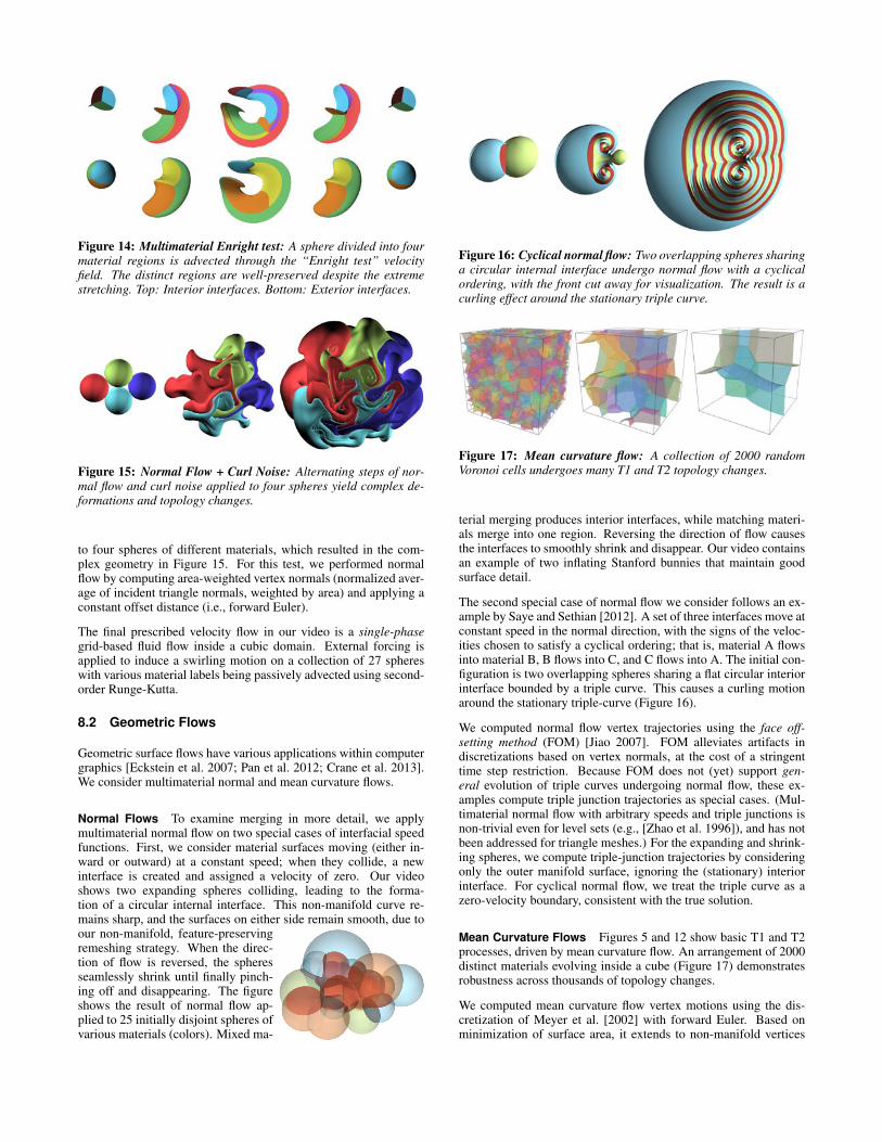
Figure 14: Multimaterial Enright test: A sphere divided into fourmaterial regions is advected through the “Enright test” velocityfield. The distinct regions are well-preserved despite the extremestretching. Top: Interior interfaces. Bottom: Exterior interfaces.
Figure 15: Normal Flow + Curl Noise: Alternating steps of nor-mal flow and curl noise applied to four spheres yield complex de-formations and topology changes.
to four spheres of different materials, which resulted in the com-plex geometry in Figure 15. For this test, we performed normalflow by computing area-weighted vertex normals (normalized aver-age of incident triangle normals, weighted by area) and applying aconstant offset distance (i.e., forward Euler).
The final prescribed velocity flow in our video is a single-phasegrid-based fluid flow inside a cubic domain. External forcing isapplied to induce a swirling motion on a collection of 27 sphereswith various material labels being passively advected using second-order Runge-Kutta.
8.2 Geometric Flows
Geometric surface flows have various applications within computergraphics [Eckstein et al. 2007; Pan et al. 2012; Crane et al. 2013].We consider multimaterial normal and mean curvature flows.
Normal Flows To examine merging in more detail, we applymultimaterial normal flow on two special cases of interfacial speedfunctions. First, we consider material surfaces moving (either in-ward or outward) at a constant speed; when they collide, a newinterface is created and assigned a velocity of zero. Our videoshows two expanding spheres colliding, leading to the forma-tion of a circular internal interface. This non-manifold curve re-mains sharp, and the surfaces on either side remain smooth, due toour non-manifold, feature-preservingremeshing strategy. When the direc-tion of flow is reversed, the spheresseamlessly shrink until finally pinch-ing off and disappearing. The figureshows the result of normal flow ap-plied to 25 initially disjoint spheres ofvarious materials (colors). Mixed ma-
Figure 16: Cyclical normal flow: Two overlapping spheres sharinga circular internal interface undergo normal flow with a cyclicalordering, with the front cut away for visualization. The result is acurling effect around the stationary triple curve.
Figure 17: Mean curvature flow: A collection of 2000 randomVoronoi cells undergoes many T1 and T2 topology changes.
terial merging produces interior interfaces, while matching materi-als merge into one region. Reversing the direction of flow causesthe interfaces to smoothly shrink and disappear. Our video containsan example of two inflating Stanford bunnies that maintain goodsurface detail.
The second special case of normal flow we consider follows an ex-ample by Saye and Sethian [2012]. A set of three interfaces move atconstant speed in the normal direction, with the signs of the veloc-ities chosen to satisfy a cyclical ordering; that is, material A flowsinto material B, B flows into C, and C flows into A. The initial con-figuration is two overlapping spheres sharing a flat circular interiorinterface bounded by a triple curve. This causes a curling motionaround the stationary triple-curve (Figure 16).
We computed normal flow vertex trajectories using the face off-setting method (FOM) [Jiao 2007]. FOM alleviates artifacts indiscretizations based on vertex normals, at the cost of a stringenttime step restriction. Because FOM does not (yet) support gen-eral evolution of triple curves undergoing normal flow, these ex-amples compute triple junction trajectories as special cases. (Mul-timaterial normal flow with arbitrary speeds and triple junctions isnon-trivial even for level sets (e.g., [Zhao et al. 1996]), and has notbeen addressed for triangle meshes.) For the expanding and shrink-ing spheres, we compute triple-junction trajectories by consideringonly the outer manifold surface, ignoring the (stationary) interiorinterface. For cyclical normal flow, we treat the triple curve as azero-velocity boundary, consistent with the true solution.
Mean Curvature Flows Figures 5 and 12 show basic T1 and T2processes, driven by mean curvature flow. An arrangement of 2000distinct materials evolving inside a cube (Figure 17) demonstratesrobustness across thousands of topology changes.
We computed mean curvature flow vertex motions using the dis-cretization of Meyer et al. [2002] with forward Euler. Based onminimization of surface area, it extends to non-manifold vertices
simply by considering the area of all incident triangles.
8.3 Comparing Snapping and Zippering
To compare snap-based merging against zipperingwe consider two spheres merging under normalflow, with the resulting shared interfaces shown tothe right. With zippering (top), the growing inter-section curve and internal interface develop in a dis-continuous and noisy fashion. By contrast, snapping(bottom) yields smoother growth of the new inter-face. The video shows that the outer geometry alsoexhibits greater overall symmetry and smoothness.
For these tests, we intentionally used normal flowbased on vertex normals. This gives merging velocities more re-flective of fluid or solid animations, which undergo many topologi-cal operations during collisions; by contrast, FOM generates vertexvelocities that (combined with small time steps) avoid merge oper-ations after initial contact. The latter yields better normal flows, asin §8.2, but does not adequately stress test complex merging.
8.4 Liquid Animation
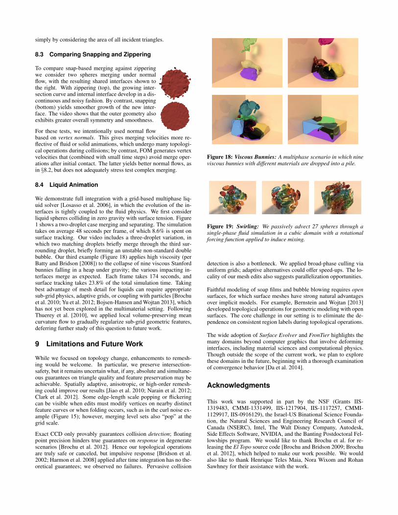
We demonstrate full integration with a grid-based multiphase liq-uid solver [Losasso et al. 2006], in which the evolution of the in-terfaces is tightly coupled to the fluid physics. We first considerliquid spheres colliding in zero gravity with surface tension. Figure1 shows a two-droplet case merging and separating. The simulationtakes on average 48 seconds per frame, of which 8.6% is spent onsurface tracking. Our video includes a three-droplet variation, inwhich two matching droplets briefly merge through the third sur-rounding droplet, briefly forming an unstable non-standard doublebubble. Our third example (Figure 18) applies high viscosity (perBatty and Bridson [2008]) to the collapse of nine viscous Stanfordbunnies falling in a heap under gravity; the various impacting in-terfaces merge as expected. Each frame takes 174 seconds, andsurface tracking takes 23.8% of the total simulation time. Takingbest advantage of mesh detail for liquids can require appropriatesub-grid physics, adaptive grids, or coupling with particles [Brochuet al. 2010; Yu et al. 2012; Bojsen-Hansen and Wojtan 2013], whichhas not yet been explored in the multimaterial setting. FollowingThuerey et al. [2010], we applied local volume-preserving meancurvature flow to gradually regularize sub-grid geometric features,deferring further study of this question to future work.
9 Limitations and Future Work
While we focused on topology change, enhancements to remesh-ing would be welcome. In particular, we preserve intersection-safety, but it remains uncertain what, if any, absolute and simultane-ous guarantees on triangle quality and feature preservation may beachievable. Spatially adaptive, anisotropic, or high-order remesh-ing could improve our results [Jiao et al. 2010; Narain et al. 2012;Clark et al. 2012]. Some edge-length scale popping or flickeringcan be visible when edits must modify vertices on nearby distinctfeature curves or when folding occurs, such as in the curl noise ex-ample (Figure 15); however, merging level sets also “pop” at thegrid scale.
Exact CCD only provably guarantees collision detection; floatingpoint precision hinders true guarantees on response in degeneratescenarios [Brochu et al. 2012]. Hence our topological operationsare truly safe or canceled, but impulsive response [Bridson et al.2002; Harmon et al. 2008] applied after time integration has no the-oretical guarantees; we observed no failures. Pervasive collision
Figure 18: Viscous Bunnies: A multiphase scenario in which nineviscous bunnies with different materials are dropped into a pile.
Figure 19: Swirling: We passively advect 27 spheres through asingle-phase fluid simulation in a cubic domain with a rotationalforcing function applied to induce mixing.
detection is also a bottleneck. We applied broad-phase culling viauniform grids; adaptive alternatives could offer speed-ups. The lo-cality of our mesh edits also suggests parallelization opportunities.
Faithful modeling of soap films and bubble blowing requires opensurfaces, for which surface meshes have strong natural advantagesover implicit models. For example, Bernstein and Wojtan [2013]developed topological operations for geometric modeling with opensurfaces. The core challenge in our setting is to eliminate the de-pendence on consistent region labels during topological operations.
The wide adoption of Surface Evolver and FronTier highlights themany domains beyond computer graphics that involve deforminginterfaces, including material sciences and computational physics.Though outside the scope of the current work, we plan to explorethese domains in the future, beginning with a thorough examinationof convergence behavior [Da et al. 2014].
Acknowledgments
This work was supported in part by the NSF (Grants IIS-1319483, CMMI-1331499, IIS-1217904, IIS-1117257, CMMI-1129917, IIS-0916129), the Israel-US Binational Science Founda-tion, the Natural Sciences and Engineering Research Council ofCanada (NSERC), Intel, The Walt Disney Company, Autodesk,Side Effects Software, NVIDIA, and the Banting Postdoctoral Fel-lowships program. We would like to thank Brochu et al. for re-leasing the El Topo source code [Brochu and Bridson 2009; Brochuet al. 2012], which helped to make our work possible. We wouldalso like to thank Henrique Teles Maia, Nora Wixom and RohanSawhney for their assistance with the work.
References
ALEXA, M. 2002. Recent advances in mesh morphing. ComputerGraphics Forum 21, 2, 173–198.
ANDERSON, J. C., GARTH, C., DUCHAINEAU, M. A., AND JOY,K. I. 2010. Smooth, volume-accurate material interface recon-struction. IEEE TVCG 16, 5, 802–814.
BARGTEIL, A. W., O’BRIEN, J. F., GOKTEKIN, T. G., ANDSTRAIN, J. A. 2006. A semi-Lagrangian contouring methodfor fluid simulation. ACM Trans. Graph. 25, 1 (Jan.), 19–38.
BATTY, C., AND BRIDSON, R. 2008. Accurate viscous free sur-faces for buckling, coiling, and rotating liquids. In Symposiumon Computer Animation, 219–228.
BERNSTEIN, G., AND WOJTAN, C. 2013. Putting holes in holeygeometry: Topology change for arbitrary surfaces. ACM Trans.Graph. (SIGGRAPH) 32, 4, 34.
BOJSEN-HANSEN, M., AND WOJTAN, C. 2013. Liquid surfacetracking with error compensation. ACM Trans. Graph. (SIG-GRAPH) 32, 4, 79:1–79:10.
BRAKKE, K. 1992. The surface evolver. Experimental Mathemat-ics 1, 2, 141–165.
BRIDSON, R., FEDKIW, R., AND ANDERSON, J. 2002. Robusttreatment of collisions, contact and friction for cloth animation.ACM Trans. Graph. (SIGGRAPH) 21, 3, 594–603.
BROCHU, T., AND BRIDSON, R. 2009. Robust topological opera-tions for dynamic explicit surfaces. SIAM J. Sci. Comput. 31, 4,2472–2493.
BROCHU, T., BATTY, C., AND BRIDSON, R. 2010. Matching fluidsimulation elements to surface geometry and topology. ACMTrans. Graph. (SIGGRAPH) 29, 4, 47.
BROCHU, T., EDWARDS, E., AND BRIDSON, R. 2012. Efficientgeometrically exact continuous collision detection. ACM Trans.Graph. (SIGGRAPH) 31, 4, 96.
CAMPEN, M., AND KOBBELT, L. 2010. Exact and robust (self-)intersections for polygonal meshes. Computer Graphics Forum(Eurographics) 29, 2 (June), 397–406.
CLARK, B., RAY, N., AND JIAO, X. 2012. Surface mesh opti-mization, adaption, and untangling with high-order accuracy. InInternational Meshing Roundtable, Springer, Berlin, X. Jiao andJ.-C. Weill, Eds., 385–402.
CLAUSEN, P., WICKE, M., SHEWCHUK, J. R., AND O’BRIEN,J. F. 2013. Simulating liquids and solid-liquid interactions withLagrangian meshes. ACM Trans. Graph. 32, 2, 17.
CRANE, K., PINKALL, U., AND SCHRODER, P. 2013. Robustfairing via conformal curvature flow. ACM Trans. Graph. (SIG-GRAPH) 32, 4, 61.
DA, F., BATTY, C., AND GRINSPUN, E. 2014. A convergencestudy of multimaterial mesh-based surface tracking. Tech. rep.,Columbia University.
DE SOUSA, F. S., MANGIAVACCHI, N., NONATO, L. G.,CASTELO, A., TOME, M. F., AND MCKEE, S. 2004. A front-tracking/front-capturing method for the simulation of 3D multi-fluid flows with free surfaces. J. Comp. Phys. 198, 2, 469–499.
DU, J., FIX, B., GLIMM, J., JIA, X., LI, X., LI, Y., AND WU, L.2006. A simple package for front tracking. J. Comp. Phys. 213,2, 613–628.
DYADECHKO, V., AND SHASHKOV, M. 2008. Reconstruction ofmulti-material interfaces from moment data. J. Comp. Phys. 227,11, 5361–5384.
ECKSTEIN, I., PONS, J.-P., TONG, Y., KUO, C.-C. J., AND DES-BRUN, M. 2007. Generalized surface flows for mesh processing.In Symposium on Geometry Processing, 183–192.
ENRIGHT, D., FEDKIW, R., FERZIGER, J., AND MITCHELL, I.2002. A hybrid particle level set method for improved interfacecapturing. J. Comp. Phys. 183, 1, 83–116.
GLIMM, J., GROVE, J. W., LI, X., SHYUE, K.-M., ZENG, Y.,AND ZHANG, Q. 1998. Three-dimensional front tracking. SIAMJ. Sci. Comput. 19, 3, 703–727.
GLIMM, J., GROVE, J. W., LI, X. L., AND TAN, D. C. 2000.Robust computational algorithms for dynamic interface trackingin three dimensions. SIAM J. Sci. Comput. 21, 6, 2240–2256.
HARMON, D., VOUGA, E., TAMSTORF, R., AND GRINSPUN, E.2008. Robust treatment of simultaneous collisions. ACM Trans.Graph. (SIGGRAPH) 27, 3, 23.
HIRT, C. W., AND NICHOLS, B. D. 1981. Volume of fluid (VOF)method for the dynamics of free boundaries. J. Comp. Phys. 39,1, 201–225.
JIAO, X., COLOMBI, A., NI, X., AND HART, J. 2010. Anisotropicmesh adaptation for evolving triangulated surfaces. Engineeringwith Computers 26, 4, 363–376.
JIAO, X. 2007. Face offsetting: A unified approach for explicitmoving interfaces. J. Comp. Phys. 220, 2, 612–625.
KIM, B. 2010. Multiphase fluid simulation using regional levelsets. ACM Trans. Graph. (SIGGRAPH Asia) 29, 6, 175.
KUPRAT, A., GEORGE, D., STRAUB, G., AND DEMIREL, M. C.2003. Modeling microstructure evolution in three dimensionswith Grain3D and LaGriT. Computational Materials Science28, 1, 199–208.
LAZAR, E. 2011. The evolution of cellular structures via curvatureflow. PhD thesis, Columbia University.
LOSASSO, F., SHINAR, T., SELLE, A., AND FEDKIW, R. 2006.Multiple interacting liquids. ACM Trans. Graph. (SIGGRAPH)25, 3, 812–819.
MCKEE, S., TOME, M. F., FERREIRA, V. G., CUMINATO, J. A.,CASTELO, A., DE SOUSA, F. S., AND MANGIAVACCHI, N.2008. The MAC method. Computers & Fluids 37, 8 (Sept.),907–930.
MEYER, M., DESBRUN, M., SCHRODER, P., AND BARR, A.2002. Discrete differential-geometry operators for triangulated2-manifolds. In VisMath, Springer-Verlag, Berlin, Germany, 35–54.
MEYER, M., WHITAKER, R. T., KIRBY, R. M., LEDERGERBER,C., AND PFISTER, H. 2008. Particle-based sampling and mesh-ing of surfaces in multimaterial volumes. IEEE TVCG 14, 6,1539–1546.
MISZTAL, M., ERLEBEN, K., BARGTEIL, A. W., CHRISTENSEN,B. B., BAERENTZEN, A., AND BRIDSON, R. 2012. Multiphaseflow of immiscible fluids on unstructured moving meshes. InSymposium on Computer Animation, Eurographics Association,Lausanne, Switzerland, 97–106.
MORA, L. B., GOTTSTEIN, G., AND SCHVINDLERMAN, L. S.2008. Three-dimensional grain growth: Analytical approachesand computer simulations. Acta Materialia 56, 1, 5915–5926.
MULLER, M., SOLENTHALER, B., KEISER, R., AND GROSS, M.2005. Particle-based fluid-fluid interaction. In Symposium onComputer Animation, ACM, Los Angeles, CA, USA, 237–244.
MULLER, M. 2009. Fast and robust tracking of fluid surfaces.In Symposium on Computer Animation, ACM, New York, NY,USA, 237–245.
NARAIN, R., SAMII, A., AND O’BRIEN, J. F. 2012. Adaptiveanisotropic remeshing for cloth simulation. ACM Trans. Graph.(SIGGRAPH Asia) 31, 6, 147.
OSHER, S., AND FEDKIW, R. 2002. Level Set Methods and Dy-namic Implicit Surfaces. Springer, New York.
PAN, H., CHOI, Y.-K., LIU, Y., HU, W., DU, Q., POLTHIER, K.,ZHANG, C., AND WANG, W. 2012. Robust modeling of con-stant mean curvature surfaces. ACM Trans. Graph. (SIGGRAPH)31, 4, 85.
PONS, J.-P., AND BOISSONNAT, J.-D. 2007. A Lagrangian ap-proach to dynamic interfaces through kinetic triangulation of theambient space. Computer Graphics Forum 26, 2, 227–239.
PONS, J.-P., AND BOISSONNAT, J.-D. 2007. Delaunay de-formable models: Topology-adaptive meshes based on the re-stricted delaunay triangulation. In CVPR, IEEE, Minneapolis,Minnesota, USA, 1–8.
QUAN, S., AND SCHMIDT, D. P. 2007. A moving mesh interfacetracking method for 3D incompressible two-phase flows. Jour-nal of Computational Physics 221, 2, 761–780.
QUAN, S., LOU, J., AND SCHMIDT, D. P. 2009. Modelingmerging and breakup in the moving mesh interface trackingmethod for multiphase flow simulations. Journal of Computa-tional Physics 228, 7, 2660–2675.
SAYE, R., AND SETHIAN, J. 2012. Analysis and applications ofthe Voronoi Implicit Interface Method. J. Comp. Phys. 231, 18,6051–6085.
SETHIAN, J. 1999. Level set methods and fast marching methods.Cambridge University Press.
SOLENTHALER, B., AND PAJAROLA, R. 2008. Density contrastSPH interfaces. In Symposium on Computer Animation, Euro-graphics Association, Dublin, 211–218.
STANCULESCU, L., CHAINE, R., AND CANI, M.-P. 2011.Freestyle: Sculpting meshes with self-adaptive topology. Com-puters and Graphics 35, 3, 614–622.
STARINSHAK, D. P., KARNI, S., AND ROE, P. L. 2014. A newlevel set model for multimaterial flows. J. Comp. Phys. In press.
SYHA, M., AND WEYGAND, D. 2010. A generalized vertex dy-namics model for grain growth in three dimensions. ModellingSimul. Mater. Sci. Eng. 18, 1, 015010.
THUEREY, N., WOJTAN, C., GROSS, M., AND TURK, G. 2010. Amultiscale approach to mesh-based surface tension flows. ACMTrans. Graph. (SIGGRAPH) 29, 3.
TOUTANT, A., MATHIEU, B., AND LEBAIGUE, O. 2012. Volume-conserving smoothing for front tracking methods. Computers &Fluids 67, 16–25.
WAKAI, F., ENOMOTO, N., AND OGAWA, H. 2000. Three-dimensional microstructural evolution in ideal grain growth -general statistics. Acta Materialia 48, 1, 1297–1311.
WEAIRE, D., AND HUTZLER, S. 2001. Physics of Foams. OxfordUniversity Press, New York.
WEYGAND, D., AND BRECHET, Y. 1999. Three-dimensionalgrain growth: a vertex dynamics simulation. Philosophical Mag-azine B 79, 5, 703–716.
WICKE, M., RITCHIE, D., KLINGNER, B. M., BURKE, S.,SHEWCHUK, J. R., AND O’BRIEN, J. F. 2010. Dynamic lo-cal remeshing for elastoplastic simulation. ACM Trans. Graph.(SIGGRAPH) 29, 4, 49.
WOJTAN, C., THUEREY, N., GROSS, M., AND TURK, G. 2009.Deforming meshes that split and merge. ACM Trans. Graph.(SIGGRAPH) 28, 3, 76.
WOJTAN, C., THUEREY, N., GROSS, M., AND TURK, G. 2010.Physically-inspired topology changes for thin fluid features.ACM Trans. Graph. (SIGGRAPH) 29, 3, 50.
WOJTAN, C., MULLER-FISCHER, M., AND BROCHU, T. 2011.Liquid simulation with mesh-based surface tracking. In SIG-GRAPH Courses, ACM, Vancouver, 8.
YU, J., WOJTAN, C., TURK, G., AND YAP, C. 2012. Explicitmesh surfaces for particle based fluids. Computer Graphics Fo-rum (Eurographics) 31, 2, 815–824.
YUAN, Z., YU, Y., AND WANG, W. 2012. Object-space multi-phase implicit functions. ACM Trans. Graph. (SIGGRAPH) 31,4, 114.
ZAHARESCU, A., BOYER, E., AND HORAUD, R. 2011. Topology-adaptive mesh deformation for surface evolution, morphing, andmultiview reconstruction. IEEE TPAMI 33, 4, 823–837.
ZHAO, H.-K., CHAN, T., MERRIMAN, B., AND OSHER, S. 1996.A variational level set approach to multiphase motion. J. Comp.Phys. 127, 1, 179–195.
ZHENG, W., YONG, J.-H., AND PAUL, J.-C. 2006. Simulation ofbubbles. In Symposium on Computer Animation, EurographicsAssociation, Vienna, 325–333.


![Topology-Adaptive Mesh Deformation for Surface Evolution, … · Topology-Adaptive Mesh Deformation for Surface Evolution, Morphing, and Multi-View Reconstruction. [Research Report]](https://img.pdfslide.net/doc/110x75/5f785df833d37a1d7d2d6044/topology-adaptive-mesh-deformation-for-surface-evolution-topology-adaptive-mesh.jpg)


![MESH GENERATION ON HIGH-CURVATURE SURFACESimr.sandia.gov/papers/imr11/miranda.pdfsurface mesh generation. Tristano and collaborators [4] proposed a similar algorithm for surface mesh](https://img.pdfslide.net/doc/110x75/5f944efbb994dc5a6467b13e/mesh-generation-on-high-curvature-surface-mesh-generation-tristano-and-collaborators.jpg)