Embed Size (px)
Citation preview
Multimodality Cardiovascular MolecularImaging Technology
Matthew O’Donnell1, Elliot R. McVeigh2, H. William Strauss3, Atsushi Tanaka4, Brett E. Bouma5,6,Guillermo J. Tearney5,6, Michael A. Guttman7, and Ernest V. Garcia8
1University of Washington, Seattle, Washington; 2Johns Hopkins University School of Medicine, Baltimore, Maryland; 3MemorialSloan-Kettering Cancer Center, New York, New York; 4Harvard Medical School, Boston, Massachusetts; 5Harvard-MIT HealthSciences and Technology, Cambridge, Massachusetts; 6Massachusetts General Hospital, Boston, Massachusetts; 7Surgivision Inc.,Baltimore, Maryland; and 8Emory University, Atlanta, Georgia
Cardiovascular molecular imaging is a new discipline that inte-grates scientific advances in both functional imaging and mo-lecular probes to improve our understanding of the molecularbasis of the cardiovascular system. These advances are drivenby in vivo imaging of molecular processes in animals, usuallysmall animals, and are rapidly moving toward clinical applica-tions. Molecular imaging has the potential to revolutionize thediagnosis and treatment of cardiovascular disease. The 2 keycomponents of all molecular imaging systems are the molecularcontrast agents and the imaging system providing spatial andtemporal localization of these agents within the body. Theymust deliver images with the appropriate sensitivity and specific-ity to drive clinical applications. As work in molecular contrastagents matures and highly sensitive and specific probes are de-veloped, these systems will provide the imaging technologies re-quired for translation into clinical tools. This is the promise ofmolecular medicine.
Key Words: molecular imaging; cardiovascular; multidisciplin-ary approach
J Nucl Med 2010; 51:38S–50SDOI: 10.2967/jnumed.109.068155
Cardiovascular molecular imaging is a new disciplinethat integrates scientific advances in both functionalimaging and molecular probes to improve our understand-ing of the molecular basis of the cardiovascular system.These advances are driven by in vivo imaging of molecu-lar processes in animals, usually small animals. A naturalprogression of this research is that our increased under-standing of these cardiovascular processes will allow us tonot only recognize the pathogenesis of the cardiac dis-ease process in individual patients but also translate thatknowledge to the development of diagnostic and therapeu-tic breakthroughs to detect and reverse disease before
permanent damage takes place. This is the promise ofmolecular medicine.
To achieve this goal, it is well accepted that a multidis-ciplinary approach is required, bringing together scientists,engineers, and clinicians. Also, the advantages of each ofthe available imaging modalities in a multimodality ap-proach is required to understand cardiovascular molecularprocesses. Advances in cardiovascular molecular imagingusing the following 4 modalities are described in thisarticle: ultrasound integrated with other techniques such asphotoacoustic imaging; real-time MRI for image-guidedtherapy; intravascular radiation detectors to measure vas-cular plaque properties; and optical coherence tomography(OCT) for microscopic coronary plaque imaging. Thefollowing sections are excellent representative examplesof the progress in and promise of the field of cardiovascularmolecular imaging.
NOVEL ULTRASOUND IMAGING APPROACHES
Ultrasound imaging has been an essential player incardiovascular diagnostics for more than a generation.However, ultrasound-based tools for molecular imaginghave been slow to develop. Molecular imaging studies todate primarily have used microbubbles. They can be coatedwith polymers or proteins and targeted like other molecularimaging agents (1). Although initially gas-filled, they canalso be filled with pharmaceuticals such as chemothera-peutics. In addition to microbubbles, perfluorocarbon-basednanoparticles targeted to cell-bound proteins becomehighly reflective and are detectable on ultrasound (2).
Because microbubbles are relatively large (;1 mm), theyare primarily limited to the vasculature. A complementarymolecular imaging approach uses a class of biologicallytargeted agents with significant optical absorption (i.e., notfluorescence) over a limited wavelength range. They aresimilar in size and binding characteristics to naturalmacromolecules and can provide high contrast per mole-cule for photoacoustic imaging. Photoacoustics combinesoptical and acoustic methods in which contrast is based onoptical absorption and spatial resolution scales with ultra-
Received Feb. 22, 2010; revision accepted Apr. 3, 2010.For correspondence or reprints contact: Elliot R. McVeigh, Johns
Hopkins University School of Medicine, 720 Rutland Ave., 720 RossBldg., Baltimore, MD 21205.
E-mail: [email protected] ª 2010 by the Society of Nuclear Medicine, Inc.
38S THE JOURNAL OF NUCLEAR MEDICINE • Vol. 51 • No. 5 (Suppl) • May 2010
by on April 10, 2018. For personal use only. jnm.snmjournals.org Downloaded from
sonic frequency. It is not sensitive to the scatteringlimitations of optical imaging and can provide real-timeimages at significant image depth with high spatial resolu-tion. Results in animal models have demonstrated itspotential for ultrasound molecular imaging beyond thevascular bed, particularly for early diagnosis of commoncancers such as those of the prostate (3).
Photoacoustic imaging can sample optical phenomenawithin tissue to a depth of several centimeters (4,5).Absorbed pulsed laser light in the near-infrared rangecreates acoustic sources whose strength is proportional tothe local absorption at the incident optical wavelength. Animage is formed using ultrasound technology, with photo-acoustic contrast directly related to optical absorption.Photoacoustics represents one of the most promising tech-niques for molecular imaging because the optical absorptionof bioconjugated nanoparticles can greatly exceed that oftissue over a range of wavelengths in which light canpenetrate a few centimeters into the body. Integratingphotoacoustic imaging into a real-time ultrasound systemcan provide simultaneous ultrasound–photoacoustic images.Finally, real-time ultrasound–photoacoustic imaging can beintegrated with molecular therapy to produce low-cost toolsfor molecular medicine.
Recent Experimental Results
As a specific example of the potential of this technology,we summarize recent results on photoacoustic imaging ofnanoparticles targeted to a specific biomarker of vascularinflammation (6,7). Excessive and uncontrolled inflamma-tion plays a key role in atherogenesis. Furthermore, chronicsystemic inflammation is a key risk factor for acceleratedatherosclerosis. Consequently, the noninvasive identifica-tion and quantification of inflammation in the vasculaturemay provide prognostic information of significant clinicalutility. There are several potential molecular biomarkers ofendothelial cell inflammation, including cytokines, tumornecrosis factor a, and cell adhesion molecules such asintercellular adhesion molecule-1 (ICAM-1). As an initialtest of photoacoustic imaging of vascular inflammation,gold nanorods were conjugated to anti-ICAM-1, whichbinds to the surface of cells overexpressing ICAM-1. Peakabsorption of the gold nanorods was tuned to a wavelengthof 700 nm for this study, far from background absorptionpeaks in tissue.
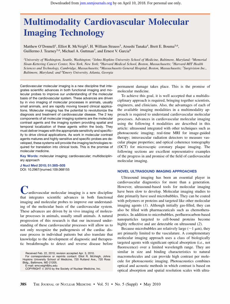
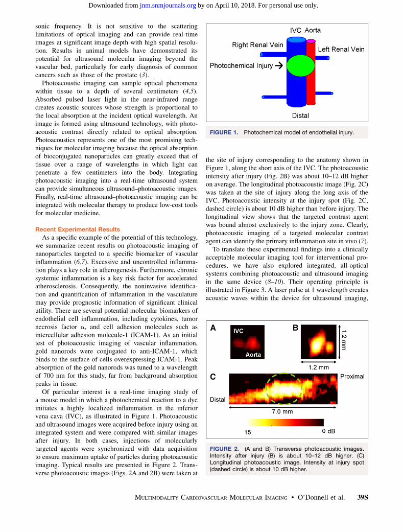
Of particular interest is a real-time imaging study ofa mouse model in which a photochemical reaction to a dyeinitiates a highly localized inflammation in the inferiorvena cava (IVC), as illustrated in Figure 1. Photoacousticand ultrasound images were acquired before injury using anintegrated system and were compared with similar imagesafter injury. In both cases, injections of molecularlytargeted agents were synchronized with data acquisitionto ensure maximum uptake of particles during photoacousticimaging. Typical results are presented in Figure 2. Trans-verse photoacoustic images (Figs. 2A and 2B) were taken at
the site of injury corresponding to the anatomy shown inFigure 1, along the short axis of the IVC. The photoacousticintensity after injury (Fig. 2B) was about 10–12 dB higheron average. The longitudinal photoacoustic image (Fig. 2C)was taken at the site of injury along the long axis of theIVC. Photoacoustic intensity at the injury spot (Fig. 2C,dashed circle) is about 10 dB higher than before injury. Thelongitudinal view shows that the targeted contrast agentwas bound almost exclusively to the injury zone. Clearly,photoacoustic imaging of a targeted molecular contrastagent can identify the primary inflammation site in vivo (7).
To translate these experimental findings into a clinicallyacceptable molecular imaging tool for interventional pro-cedures, we have also explored integrated, all-opticalsystems combining photoacoustic and ultrasound imagingin the same device (8–10). Their operating principle isillustrated in Figure 3. A laser pulse at 1 wavelength createsacoustic waves within the device for ultrasound imaging,
FIGURE 1. Photochemical model of endothelial injury.
FIGURE 2. (A and B) Transverse photoacoustic images.Intensity after injury (B) is about 10–12 dB higher. (C)Longitudinal photoacoustic image. Intensity at injury spot(dashed circle) is about 10 dB higher.
MULTIMODALITY CARDIOVASCULAR MOLECULAR IMAGING • O’Donnell et al. 39S
by on April 10, 2018. For personal use only. jnm.snmjournals.org Downloaded from
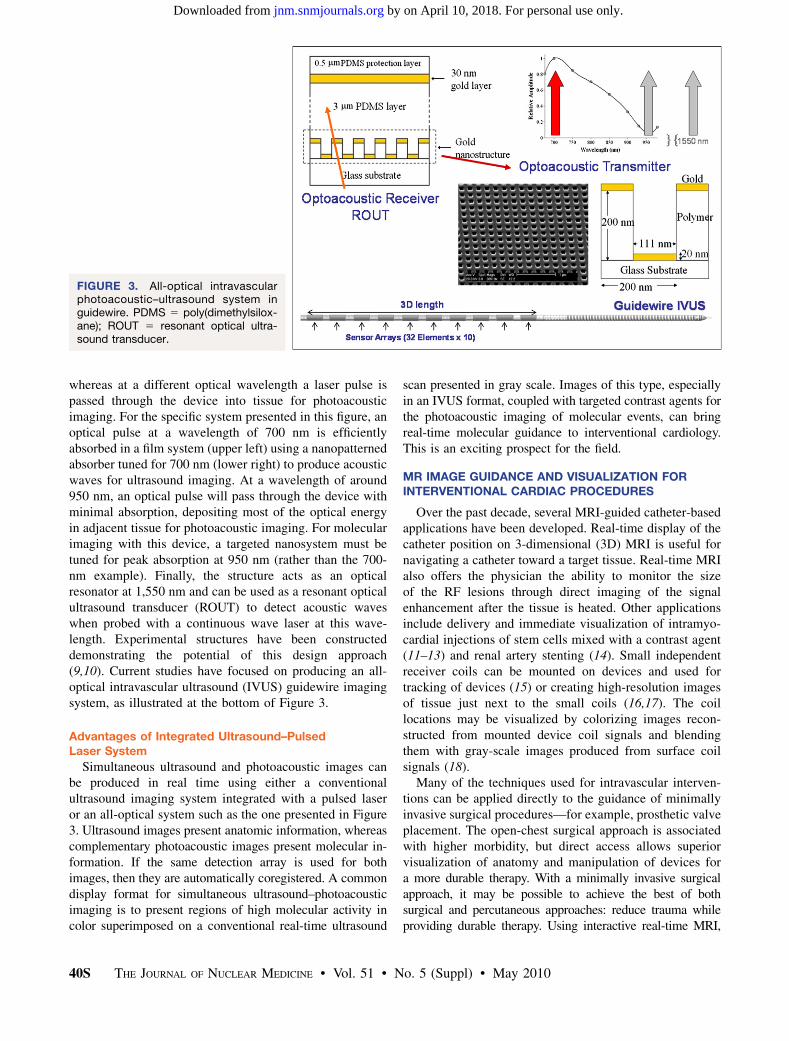
whereas at a different optical wavelength a laser pulse ispassed through the device into tissue for photoacousticimaging. For the specific system presented in this figure, anoptical pulse at a wavelength of 700 nm is efficientlyabsorbed in a film system (upper left) using a nanopatternedabsorber tuned for 700 nm (lower right) to produce acousticwaves for ultrasound imaging. At a wavelength of around950 nm, an optical pulse will pass through the device withminimal absorption, depositing most of the optical energyin adjacent tissue for photoacoustic imaging. For molecularimaging with this device, a targeted nanosystem must betuned for peak absorption at 950 nm (rather than the 700-nm example). Finally, the structure acts as an opticalresonator at 1,550 nm and can be used as a resonant opticalultrasound transducer (ROUT) to detect acoustic waveswhen probed with a continuous wave laser at this wave-length. Experimental structures have been constructeddemonstrating the potential of this design approach(9,10). Current studies have focused on producing an all-optical intravascular ultrasound (IVUS) guidewire imagingsystem, as illustrated at the bottom of Figure 3.
Advantages of Integrated Ultrasound–PulsedLaser System
Simultaneous ultrasound and photoacoustic images canbe produced in real time using either a conventionalultrasound imaging system integrated with a pulsed laseror an all-optical system such as the one presented in Figure3. Ultrasound images present anatomic information, whereascomplementary photoacoustic images present molecular in-formation. If the same detection array is used for bothimages, then they are automatically coregistered. A commondisplay format for simultaneous ultrasound–photoacousticimaging is to present regions of high molecular activity incolor superimposed on a conventional real-time ultrasound
scan presented in gray scale. Images of this type, especiallyin an IVUS format, coupled with targeted contrast agents forthe photoacoustic imaging of molecular events, can bringreal-time molecular guidance to interventional cardiology.This is an exciting prospect for the field.
MR IMAGE GUIDANCE AND VISUALIZATION FORINTERVENTIONAL CARDIAC PROCEDURES
Over the past decade, several MRI-guided catheter-basedapplications have been developed. Real-time display of thecatheter position on 3-dimensional (3D) MRI is useful fornavigating a catheter toward a target tissue. Real-time MRIalso offers the physician the ability to monitor the sizeof the RF lesions through direct imaging of the signalenhancement after the tissue is heated. Other applicationsinclude delivery and immediate visualization of intramyo-cardial injections of stem cells mixed with a contrast agent(11–13) and renal artery stenting (14). Small independentreceiver coils can be mounted on devices and used fortracking of devices (15) or creating high-resolution imagesof tissue just next to the small coils (16,17). The coillocations may be visualized by colorizing images recon-structed from mounted device coil signals and blendingthem with gray-scale images produced from surface coilsignals (18).
Many of the techniques used for intravascular interven-tions can be applied directly to the guidance of minimallyinvasive surgical procedures—for example, prosthetic valveplacement. The open-chest surgical approach is associatedwith higher morbidity, but direct access allows superiorvisualization of anatomy and manipulation of devices fora more durable therapy. With a minimally invasive surgicalapproach, it may be possible to achieve the best of bothsurgical and percutaneous approaches: reduce trauma whileproviding durable therapy. Using interactive real-time MRI,
FIGURE 3. All-optical intravascularphotoacoustic–ultrasound system inguidewire. PDMS 5 poly(dimethylsilox-ane); ROUT 5 resonant optical ultra-sound transducer.
40S THE JOURNAL OF NUCLEAR MEDICINE • Vol. 51 • No. 5 (Suppl) • May 2010
by on April 10, 2018. For personal use only. jnm.snmjournals.org Downloaded from
the surgeon positioned the prosthetic valve in the correctlocation at the aortic annulus within 90 s. Ventricular function,blood flow through the valve, and myocardial perfusion wereimmediately evaluated with MRI (19,20).
Cardiac Interventional MRI System
New Magnet Configuration. A new 1.5-T magnet designhas recently become available; it is a closed-bore designwith shorter depth and wider opening (Espree; SiemensMedical Solutions). It has a 120-cm-long bore that is 70 cmwide; this size provides greater accessibility with only anapproximately 20% loss in imaging speed. The imagingfield of view was reduced to 30 cm but was adequate formany cardiac interventions. This magnet bore is shortenough for a surgeon to reach the center of the magnetand wide enough to allow placement and manipulation ofinstruments over the patient’s body.
Interventional Imaging Platform. The platforms devel-oped at the National Heart, Lung and Blood Institute(NHLBI) for interventional real-time MRI (rtMRI) usedclinical 1.5-T MRI scanners (Sonata with 8 receiverchannels, Espree with 18 channels, and Avanto with 32channels; Siemens Medical Solutions), with additionalsoftware for socket communication over gigabit Ethernetwith a Linux workstation (8–central processing unit, 64-bitAMD Opteron; HPC Systems) running custom software forrapid image reconstruction, display, and 3D rendering(18,21). The workstation is connected directly to theimage-reconstruction computer of the MRI scanner forquick access to the raw echo data.
At the beginning of a scan, imaging parameters are sentfrom the scanner to the workstation for initialization of thereconstruction program. At the end of each image acquisi-tion, a packet of data is sent containing dynamic imagingparameters and the raw MRI data. Commands are sent tothe scanner in response to user input via the same networkinterface.
Real-Time Imaging Features. A useful navigation tech-nique using adaptively oriented projection navigation (18)was designed to facilitate steering of an active devicetoward target tissue. A device-only projection image andat least 1 standard thin-slice image are displayed together ina 3D rendering, all updated using real-time imaging. As theuser interactively rotates the 3D rendering, the scannerautomatically changes the projection direction, analogous tochanging x-ray gantry position during fluoroscopy. Thisprovides a real-time 3D view of the catheter position andtrajectory with respect to the thin-slice image plane. Foranatomic context, the thin-slice image is positioned to containtarget tissue, and the combination of projection and thin-sliceviews can be used to navigate the device toward the target.
The NHLBI rtMRI implementation contains the pro-jection imaging features and many other interactive fea-tures, which can be controlled by simple keyboard ormouse operation without stopping the scanner. The follow-ing is a partial list of interactive features available (18,22):
• Enable or disable acquisition of selected slices. Thisfeature was often used when slices were initiallyprescribed for all stages of the procedure, and thenonly those needed at the time were enabled.
• Display each slice in a separate window and a 3Drendering showing the respective location in space(Figs. 4 and 5). This feature provided simultaneous viewsof all slices and devices in 1 window, from any angle.
• Highlight device channels in different colors, blendedwith gray-scale images from surface coils (Fig. 5). Thedevice signal magnitude can be squared to sharpen thedevice profile.
• Mark reference points. Reference points are displayedas separate graphic objects, such as small coloredspheres, in the 3D rendering. This feature is used tomark anatomic structures for device positioning andtargeting (Fig. 5).
• Enable or disable the device-only projection view onselected slices to show the entire device if it exits fromthe thinner imaging slice.
• Enable or disable adaptive projection navigation modefor 3D projection views of the device.
• Change the acceleration factor.• Enable subtraction imaging for enhancing contrast
injections.• Enable saving of raw data to files. The same program
can be used later to review the images with the same ordifferent options for reconstruction or display. Severaldisplay and rendering parameters (such as 3D renderingorientation, highlight colors, and window positions)are also saved. Postprocedure review, therefore, canmimic how the images were displayed during theactual procedure.
Initial Preclinical Procedures
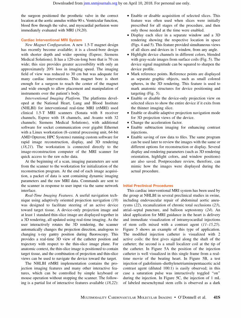
This cardiac interventional MRI system has been used bythe group at NHLBI in several preclinical studies in swine,including endovascular repair of abdominal aortic aneu-rysms (22), recanalization of chronic total occlusions (23),atrial–septal puncture, and balloon septostomy (24). Anideal application for MRI guidance in the heart is deliveryand immediate visualization of intramyocardial injectionsof stem cells mixed with a contrast agent (11–15,25).Figure 5 shows an example of this type of application.The modified injection catheter is visualized with 2active coils: the first gives signal along the shaft of thecatheter; the second is a small localizer coil at the tip ofthe catheter. In Figure 5A the position of the injectioncatheter is well visualized in this single frame from a real-time movie of the beating heart. In Figure 5B, a testinjection of gadolinium–diethylenetriaminepentaacetic acidcontrast agent (diluted 100:1) is easily observed; in thiscase a saturation pulse was interactively toggled ‘‘on’’during the injection. In Figure 5C, the injection of 1 mLof labeled mesenchymal stem cells is observed as a dark
MULTIMODALITY CARDIOVASCULAR MOLECULAR IMAGING • O’Donnell et al. 41S
by on April 10, 2018. For personal use only. jnm.snmjournals.org Downloaded from
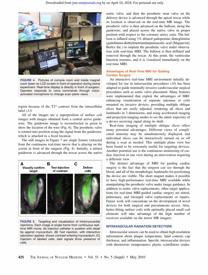
region because of the T2* contrast from the intracellularlabel (13)
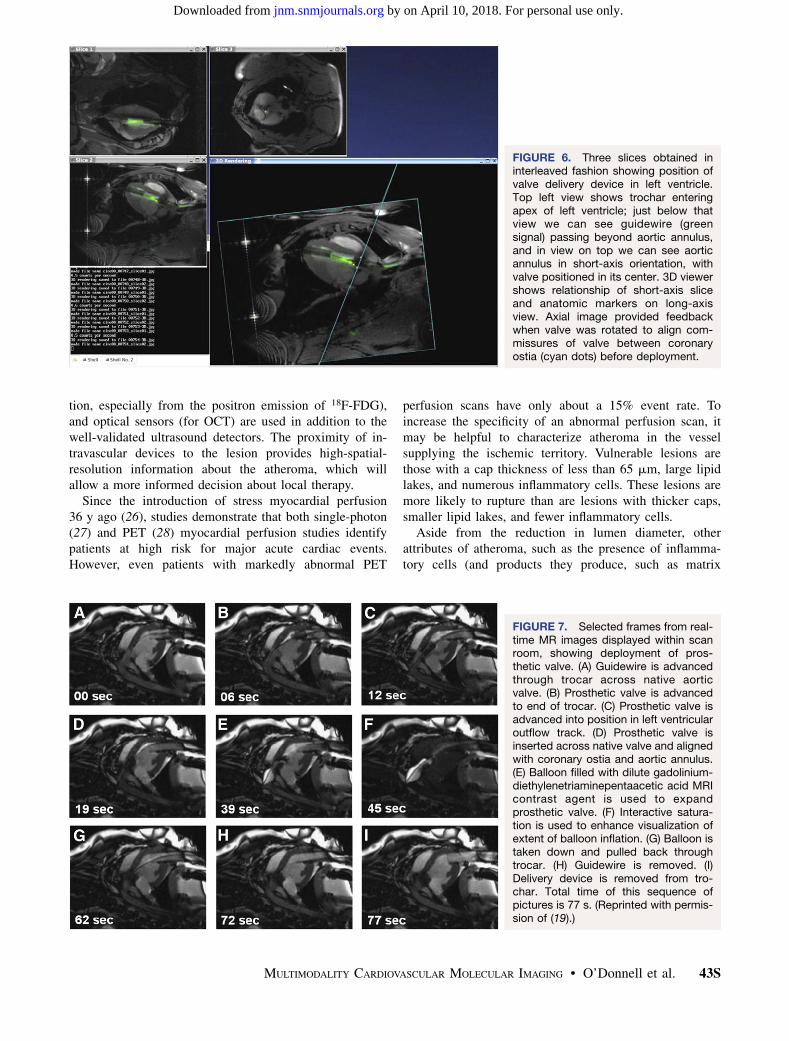
All of the images are a superposition of surface coilimages with images obtained from a central active guide-wire. The guidewire image is reconstructed in green toshow the location of the wire (Fig. 6). The prosthetic valveis rotated into position using the signal from the guidewire,which is attached in a fixed location.
The still images in Figure 7 are single frames extractedfrom the continuous real-time movie that is playing on thescreen in front of the surgeon (Fig. 4). Initially, a nitinolguidewire is advanced through the trocar across the native
aortic valve, and then the prosthetic stent valve on thedelivery device is advanced through the apical trocar whileits location is observed on the real-time MR image. Theprosthetic valve is then advanced on the balloon, along theguidewire, and placed across the native valve in properposition with respect to the coronary artery ostia. The bal-loon is inflated using 1% diluted gadopentate dimeglumine(gadolinium-diethylenetriaminepentaacetic acid [Magnavist];Berlex Inc.) to implant the prosthetic valve under observa-tion with real-time MRI. The balloon is then deflated andremoved through the trocar. At this point, the ventricularfunction resumes, and it is visualized immediately on thereal-time MRI.
Advantages of Real-Time MRI for GuidingCardiac Surgery
An interactive real-time MRI environment initially de-veloped for use in intravascular procedures (18) has beenadapted to guide minimally invasive cardiovascular surgicalprocedures such as aortic valve placement. Many featureswere implemented that exploit the advantages of MRI:enhancing visualization of separate antennae or coilsmounted on invasive devices, providing multiple obliqueslices that are easily adjusted, rendering all slices andlandmarks in 3 dimensions, and using accelerated imagingand projection imaging modes to see the entire trajectory ofa device receiving signal along its shaft.
Real-time imaging of multiple oblique slices offersmany potential advantages. Different views of compli-cated anatomy may be simultaneously displayed, andindividual slices can be interactively turned on or offduring a scan as needed. This multiple plane view hasbeen found to be extremely useful for targeting devices.Another potential use is the continuous monitoring of car-diac function in one view during an intervention requiringa different view.
The distinct advantage of MRI for guiding cardiacsurgery is the fact that the surgeon can see through theblood, and all of the morphologic landmarks for positioningthe device are visible. The short magnet makes it possibleto have high-performance real-time MRI available whilemanipulating the prosthetic valve under image guidance. Inaddition to aortic valve replacements, other target applica-tions for real-time MRI-guided cardiac surgery are mitral,pulmonary, and tricuspid valve replacements or repairs.Future work will concentrate on the development of noveldevices for both surgical and percutaneous access. Also,better-fitting surface coils with optimally placed small coilelements will take advantage of the high number ofreceivers available on the newer MR imagers.
INTRAVASCULAR RADIATION DETECTORS
Intravascular sensors can be used to obtain high-resolutioninformation about plaque temperature, lipid content, capthickness, and inflammation. Specific intravascular deviceswith thermistors (temperature), plastic scintillators (radia-
FIGURE 4. Pictures of console room and inside magnetroom (seen on LCD screen in front of operator) during swineexperiment. Real-time display is directly in front of surgeon.Operator responds to voice commands through voice-activated microphone to change scan plane views.
FIGURE 5. Targeting and visualization of intramyocardialinjections. Each image is single frame from continuous real-time MRI movie. (A) Injection catheter in position with distaltip against myocardium. (B) Test injection, with interactivesaturation applied, shows contrast entering myocardium. (C)Injection of labeled cells; dark signals show presence ofcells.
42S THE JOURNAL OF NUCLEAR MEDICINE • Vol. 51 • No. 5 (Suppl) • May 2010
by on April 10, 2018. For personal use only. jnm.snmjournals.org Downloaded from
tion, especially from the positron emission of 18F-FDG),and optical sensors (for OCT) are used in addition to thewell-validated ultrasound detectors. The proximity of in-travascular devices to the lesion provides high-spatial-resolution information about the atheroma, which willallow a more informed decision about local therapy.
Since the introduction of stress myocardial perfusion36 y ago (26), studies demonstrate that both single-photon(27) and PET (28) myocardial perfusion studies identifypatients at high risk for major acute cardiac events.However, even patients with markedly abnormal PET
perfusion scans have only about a 15% event rate. Toincrease the specificity of an abnormal perfusion scan, itmay be helpful to characterize atheroma in the vesselsupplying the ischemic territory. Vulnerable lesions arethose with a cap thickness of less than 65 mm, large lipidlakes, and numerous inflammatory cells. These lesions aremore likely to rupture than are lesions with thicker caps,smaller lipid lakes, and fewer inflammatory cells.
Aside from the reduction in lumen diameter, otherattributes of atheroma, such as the presence of inflamma-tory cells (and products they produce, such as matrix
FIGURE 6. Three slices obtained ininterleaved fashion showing position ofvalve delivery device in left ventricle.Top left view shows trochar enteringapex of left ventricle; just below thatview we can see guidewire (greensignal) passing beyond aortic annulus,and in view on top we can see aorticannulus in short-axis orientation, withvalve positioned in its center. 3D viewershows relationship of short-axis sliceand anatomic markers on long-axisview. Axial image provided feedbackwhen valve was rotated to align com-missures of valve between coronaryostia (cyan dots) before deployment.
FIGURE 7. Selected frames from real-time MR images displayed within scanroom, showing deployment of pros-thetic valve. (A) Guidewire is advancedthrough trocar across native aorticvalve. (B) Prosthetic valve is advancedto end of trocar. (C) Prosthetic valve isadvanced into position in left ventricularoutflow track. (D) Prosthetic valve isinserted across native valve and alignedwith coronary ostia and aortic annulus.(E) Balloon filled with dilute gadolinium-diethylenetriaminepentaacetic acid MRIcontrast agent is used to expandprosthetic valve. (F) Interactive satura-tion is used to enhance visualization ofextent of balloon inflation. (G) Balloon istaken down and pulled back throughtrocar. (H) Guidewire is removed. (I)Delivery device is removed from tro-char. Total time of this sequence ofpictures is 77 s. (Reprinted with permis-sion of (19).)
MULTIMODALITY CARDIOVASCULAR MOLECULAR IMAGING • O’Donnell et al. 43S
by on April 10, 2018. For personal use only. jnm.snmjournals.org Downloaded from
metalloproteinase (29)), may be useful in characterizing thelesion. Numerous other markers—including the presence oflow-density lipoprotein, oxidized low-density lipoprotein,apoptosis, cap thickness, total lipid content, and integrinexpression—exist.
Histopathologic evidence (30,31) supports the importanceof inflammation as a major constituent of vulnerable lesions.One hypothesis is that combining data from a myocardialperfusion scan demonstrating ischemia in a particularterritory with specific information on the presence ofinflammatory cells in the wall of the vessel perfusing theregion will identify lesions at high risk for causing majorevents.
Inflammatory cells in the atheroma can be identified onthe basis of their upregulation of chemotactic receptors(such as monocyte chemoattractant peptide-1 [also calledC-C chemokine receptor 2]) (32–34) on the surface of theactivated macrophage. An alternative approach uses theknown increase in metabolism of the activated cells.Activated macrophages increased their metabolic rate by10–100 times, compared with baseline. These cells useexogenous glucose to meet their energy needs. As a result,18F-FDG PET scans (in conjunction with CT or MRI foranatomic localization) have been advocated to localizethese lesions (35).
Interrogating specific lesions in the catheterization lab-oratory for the degree of inflammation may distinguishlesions that are likely to progress from those that are stable.This information may be useful in selecting areas forspecific treatment, such as balloon angioplasty alone,angioplasty plus bare metal stents, or angioplasty plusdrug-eluting stents.
An intravascular radiation-sensitive catheter can localize(and quantify) inflammation in an atheroma. The maximumpath length of the positron emitted by 18F is 3 mm (meanpath, 1 mm). This path length is well suited to detection bya 3-French catheter using either a plastic scintillator matedto an optical fiber or a solid-state detector such as cadmiumtelluride mounted on the guidewire of a coronary arterycatheter.
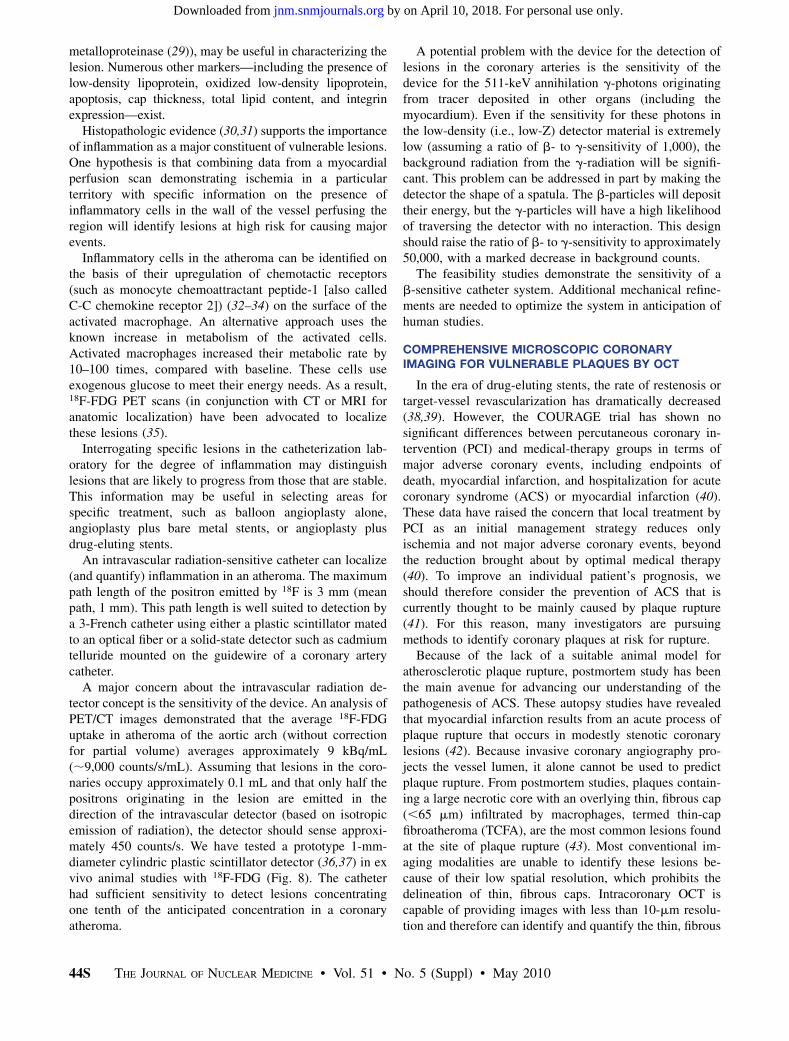
A major concern about the intravascular radiation de-tector concept is the sensitivity of the device. An analysis ofPET/CT images demonstrated that the average 18F-FDGuptake in atheroma of the aortic arch (without correctionfor partial volume) averages approximately 9 kBq/mL(;9,000 counts/s/mL). Assuming that lesions in the coro-naries occupy approximately 0.1 mL and that only half thepositrons originating in the lesion are emitted in thedirection of the intravascular detector (based on isotropicemission of radiation), the detector should sense approxi-mately 450 counts/s. We have tested a prototype 1-mm-diameter cylindric plastic scintillator detector (36,37) in exvivo animal studies with 18F-FDG (Fig. 8). The catheterhad sufficient sensitivity to detect lesions concentratingone tenth of the anticipated concentration in a coronaryatheroma.
A potential problem with the device for the detection oflesions in the coronary arteries is the sensitivity of thedevice for the 511-keV annihilation g-photons originatingfrom tracer deposited in other organs (including themyocardium). Even if the sensitivity for these photons inthe low-density (i.e., low-Z) detector material is extremelylow (assuming a ratio of b- to g-sensitivity of 1,000), thebackground radiation from the g-radiation will be signifi-cant. This problem can be addressed in part by making thedetector the shape of a spatula. The b-particles will deposittheir energy, but the g-particles will have a high likelihoodof traversing the detector with no interaction. This designshould raise the ratio of b- to g-sensitivity to approximately50,000, with a marked decrease in background counts.
The feasibility studies demonstrate the sensitivity of ab-sensitive catheter system. Additional mechanical refine-ments are needed to optimize the system in anticipation ofhuman studies.
COMPREHENSIVE MICROSCOPIC CORONARYIMAGING FOR VULNERABLE PLAQUES BY OCT
In the era of drug-eluting stents, the rate of restenosis ortarget-vessel revascularization has dramatically decreased(38,39). However, the COURAGE trial has shown nosignificant differences between percutaneous coronary in-tervention (PCI) and medical-therapy groups in terms ofmajor adverse coronary events, including endpoints ofdeath, myocardial infarction, and hospitalization for acutecoronary syndrome (ACS) or myocardial infarction (40).These data have raised the concern that local treatment byPCI as an initial management strategy reduces onlyischemia and not major adverse coronary events, beyondthe reduction brought about by optimal medical therapy(40). To improve an individual patient’s prognosis, weshould therefore consider the prevention of ACS that iscurrently thought to be mainly caused by plaque rupture(41). For this reason, many investigators are pursuingmethods to identify coronary plaques at risk for rupture.
Because of the lack of a suitable animal model foratherosclerotic plaque rupture, postmortem study has beenthe main avenue for advancing our understanding of thepathogenesis of ACS. These autopsy studies have revealedthat myocardial infarction results from an acute process ofplaque rupture that occurs in modestly stenotic coronarylesions (42). Because invasive coronary angiography pro-jects the vessel lumen, it alone cannot be used to predictplaque rupture. From postmortem studies, plaques contain-ing a large necrotic core with an overlying thin, fibrous cap(,65 mm) infiltrated by macrophages, termed thin-capfibroatheroma (TCFA), are the most common lesions foundat the site of plaque rupture (43). Most conventional im-aging modalities are unable to identify these lesions be-cause of their low spatial resolution, which prohibits thedelineation of thin, fibrous caps. Intracoronary OCT iscapable of providing images with less than 10-mm resolu-tion and therefore can identify and quantify the thin, fibrous
44S THE JOURNAL OF NUCLEAR MEDICINE • Vol. 51 • No. 5 (Suppl) • May 2010
by on April 10, 2018. For personal use only. jnm.snmjournals.org Downloaded from
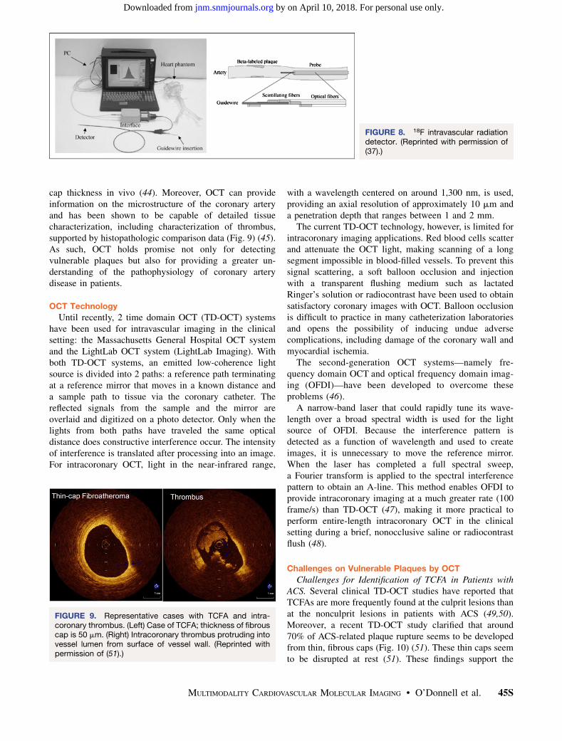
cap thickness in vivo (44). Moreover, OCT can provideinformation on the microstructure of the coronary arteryand has been shown to be capable of detailed tissuecharacterization, including characterization of thrombus,supported by histopathologic comparison data (Fig. 9) (45).As such, OCT holds promise not only for detectingvulnerable plaques but also for providing a greater un-derstanding of the pathophysiology of coronary arterydisease in patients.
OCT Technology
Until recently, 2 time domain OCT (TD-OCT) systemshave been used for intravascular imaging in the clinicalsetting: the Massachusetts General Hospital OCT systemand the LightLab OCT system (LightLab Imaging). Withboth TD-OCT systems, an emitted low-coherence lightsource is divided into 2 paths: a reference path terminatingat a reference mirror that moves in a known distance anda sample path to tissue via the coronary catheter. Thereflected signals from the sample and the mirror areoverlaid and digitized on a photo detector. Only when thelights from both paths have traveled the same opticaldistance does constructive interference occur. The intensityof interference is translated after processing into an image.For intracoronary OCT, light in the near-infrared range,
with a wavelength centered on around 1,300 nm, is used,providing an axial resolution of approximately 10 mm anda penetration depth that ranges between 1 and 2 mm.
The current TD-OCT technology, however, is limited forintracoronary imaging applications. Red blood cells scatterand attenuate the OCT light, making scanning of a longsegment impossible in blood-filled vessels. To prevent thissignal scattering, a soft balloon occlusion and injectionwith a transparent flushing medium such as lactatedRinger’s solution or radiocontrast have been used to obtainsatisfactory coronary images with OCT. Balloon occlusionis difficult to practice in many catheterization laboratoriesand opens the possibility of inducing undue adversecomplications, including damage of the coronary wall andmyocardial ischemia.
The second-generation OCT systems—namely fre-quency domain OCT and optical frequency domain imag-ing (OFDI)—have been developed to overcome theseproblems (46).
A narrow-band laser that could rapidly tune its wave-length over a broad spectral width is used for the lightsource of OFDI. Because the interference pattern isdetected as a function of wavelength and used to createimages, it is unnecessary to move the reference mirror.When the laser has completed a full spectral sweep,a Fourier transform is applied to the spectral interferencepattern to obtain an A-line. This method enables OFDI toprovide intracoronary imaging at a much greater rate (100frame/s) than TD-OCT (47), making it more practical toperform entire-length intracoronary OCT in the clinicalsetting during a brief, nonocclusive saline or radiocontrastflush (48).
Challenges on Vulnerable Plaques by OCT
Challenges for Identification of TCFA in Patients withACS. Several clinical TD-OCT studies have reported thatTCFAs are more frequently found at the culprit lesions thanat the nonculprit lesions in patients with ACS (49,50).Moreover, a recent TD-OCT study clarified that around70% of ACS-related plaque rupture seems to be developedfrom thin, fibrous caps (Fig. 10) (51). These thin caps seemto be disrupted at rest (51). These findings support the
FIGURE 8. 18F intravascular radiationdetector. (Reprinted with permission of(37).)
FIGURE 9. Representative cases with TCFA and intra-coronary thrombus. (Left) Case of TCFA; thickness of fibrouscap is 50 mm. (Right) Intracoronary thrombus protruding intovessel lumen from surface of vessel wall. (Reprinted withpermission of (51).)
MULTIMODALITY CARDIOVASCULAR MOLECULAR IMAGING • O’Donnell et al. 45S
by on April 10, 2018. For personal use only. jnm.snmjournals.org Downloaded from
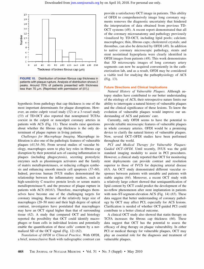
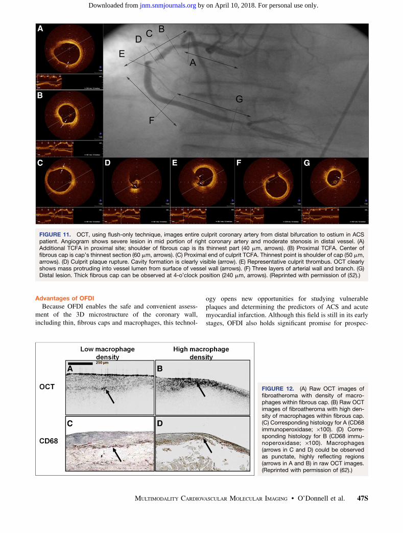
hypothesis from pathology that cap thickness is one of themost important determinants for plaque disruptions. How-ever, an entire culprit vessel study (52) or a 3-vessel study(53) of TD-OCT also reported that nonruptured TCFAscoexist in the culprit or nonculprit coronary arteries inpatients with ACS (Fig. 11). These results raise questionsabout whether the fibrous cap thickness is the only de-terminant of plaque rupture in living patients.
Challenges for Macrophage Imaging. Macrophage in-filtration is also one of the pathologic features of vulnerableplaques (43,54–56). From several studies of vascular bi-ology, macrophages seem to play key roles in fibrous capdisruption by their potential acts of causing inflammation inplaques (including phagocytosis), secreting proteolyticenzymes such as plasminogen activators and the familyof matrix metalloproteinases, or reducing collagen synthe-sis and enhancing smooth muscle cell apoptosis (57–60).Indeed, previous human IVUS studies demonstrated therelationship between the inflammatory markers, such ashigh-sensitivity C-reactive protein levels or serum matrixmetalloproteinase-9, and the presence of plaque rupture inpatients with ACS (60,61). Therefore, macrophages them-selves have become one of the challenging targets forcoronary imaging. Because of the relatively large size ofmacrophages (20–50 mm) and their high degree of opticalcontrast, investigators have postulated that macrophagesmay have an OCT signal higher than that of surroundingtissue (62). A study that compared OCT and histologyreported the possibility that OCT could identify macro-phages or foam cells in individual lesions and potentiallyenable the quantification of these cells’ content by a nor-malized SD of the OCT signal (Fig. 12) (62).
Translation of OFDI to Clinical Practice. With OFDI,a brief, nonocclusive flush with radiographic contrast can
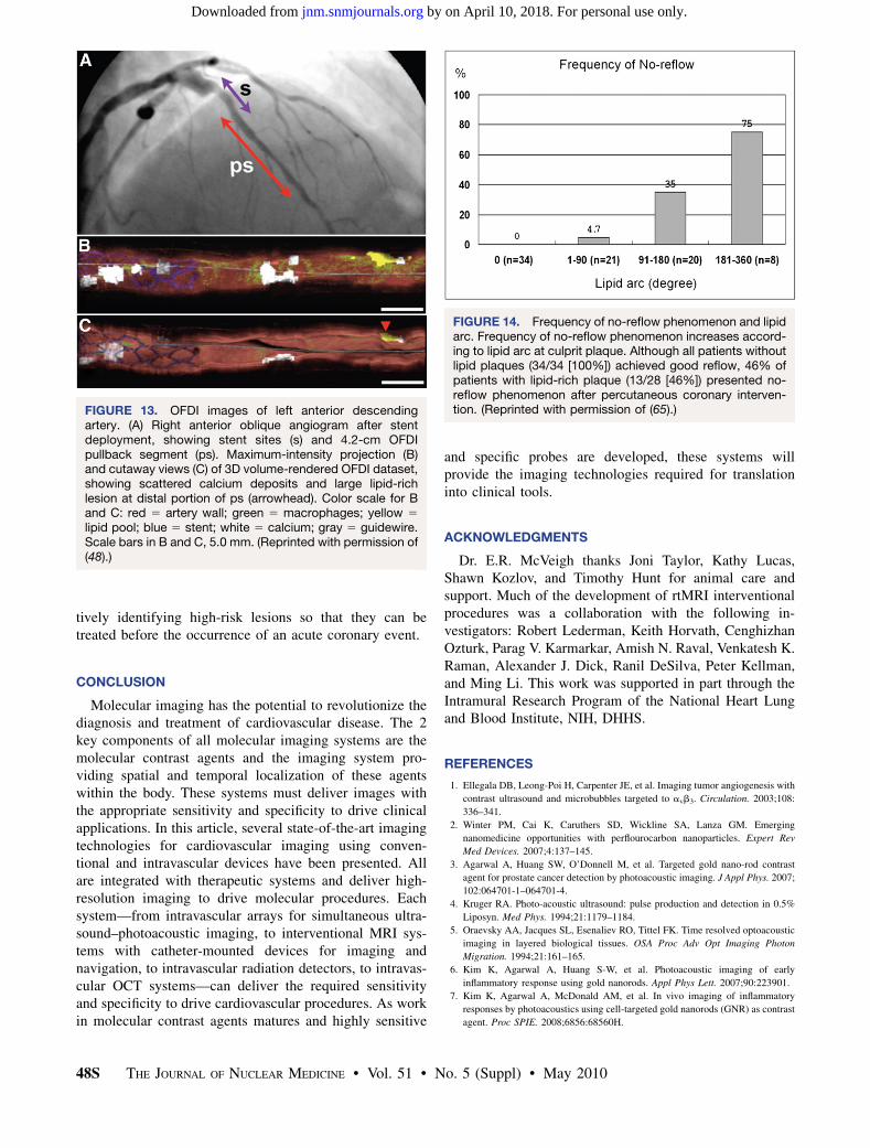
provide a satisfactory OCT image in patients. This abilityof OFDI to comprehensively image long coronary seg-ments removes the diagnostic uncertainty that hinderedthe interpretation of data obtained from previous TD-OCT systems (48). A recent report demonstrated that allof the coronary microanatomy and pathology previouslyvisualized by TD-OCT, including lipid pools; calcium;macrophages; thin, fibrous caps; cholesterol crystals; andthrombus, can also be detected by OFDI (48). In additionto native coronary microscopic pathology, stents andstent neointimal hyperplasia were clearly identified inOFDI images from patients (48). This work demonstratesthat 3D microscopic images of long coronary arterysegments can now be acquired conveniently in the cath-eterization lab, and as a result, OFDI may be considereda viable tool for studying the pathophysiology of ACS(Fig. 13).
Future Directions and Clinical Implications
Natural History of Vulnerable Plaques. Although au-topsy studies have contributed to our better understandingof the etiology of ACS, their retrospective nature limits ourability to interrogate a natural history of vulnerable plaquesand the clinical significance of these lesions. To know theevolution of vulnerable plaques would improve our un-derstanding of ACS and patients’ care.
Currently, only OFDI seems to have the potential toprovide reliable microscopic features of vulnerable plaquesin whole coronary arteries. OFDI would be a promisingdevice to clarify the natural history of vulnerable plaques.Now, several OCT–OFDI studies have been performedthroughout the world.
PCI and Medical Therapy for Vulnerable Plaques:Guided OCT–OFDI. Until recently, IVUS was the goldstandard imaging modality to assist in PCI procedures.However, a clinical study reported that OCT for monitoringstent deployments can provide contrast and resolutionsuperior to those of IVUS for depicting arterial disease(63). An OCT study demonstrated different vascular re-sponses between patients with unstable and patients withstable angina (64). Moreover, a recent OCT study witha relatively large cohort showed that semiquantification oflipid content by OCT could predict the development of theno-reflow phenomenon after stent implantation in patientswith non–ST-segment-elevation ACS (Fig. 14) (65). Thesedata suggest that better understanding of coronary pathol-ogy by OCT may affect PCI, especially for ACS lesions.Clarification is needed of whether OCT-guided PCI couldcontribute to a better clinical outcome.
A clinical OCT study also showed that statin therapy onTCFA increases the fibrous cap thickness (66). Thesedata suggest that OCT has the potential to assess theefficacy of drug therapy on plaque vulnerability. In eitherPCI or medical therapy for vulnerable plaques, OCT mayplay an essential role for the diagnosis and treatment ofvulnerable plaques.
FIGURE 10. Distribution of broken fibrous cap thickness inpatients with plaque rupture. Analysis of distribution shows 2peaks. Around 70% of patients presented with thicknessless than 70 mm. (Reprinted with permission of (51).)
46S THE JOURNAL OF NUCLEAR MEDICINE • Vol. 51 • No. 5 (Suppl) • May 2010
by on April 10, 2018. For personal use only. jnm.snmjournals.org Downloaded from
Advantages of OFDI
Because OFDI enables the safe and convenient assess-ment of the 3D microstructure of the coronary wall,including thin, fibrous caps and macrophages, this technol-
ogy opens new opportunities for studying vulnerableplaques and determining the predictors of ACS and acutemyocardial infarction. Although this field is still in its earlystages, OFDI also holds significant promise for prospec-
FIGURE 11. OCT, using flush-only technique, images entire culprit coronary artery from distal bifurcation to ostium in ACSpatient. Angiogram shows severe lesion in mid portion of right coronary artery and moderate stenosis in distal vessel. (A)Additional TCFA in proximal site; shoulder of fibrous cap is its thinnest part (40 mm, arrows). (B) Proximal TCFA. Center offibrous cap is cap’s thinnest section (60 mm, arrows). (C) Proximal end of culprit TCFA. Thinnest point is shoulder of cap (50 mm,arrows). (D) Culprit plaque rupture. Cavity formation is clearly visible (arrow). (E) Representative culprit thrombus. OCT clearlyshows mass protruding into vessel lumen from surface of vessel wall (arrows). (F) Three layers of arterial wall and branch. (G)Distal lesion. Thick fibrous cap can be observed at 4-o’clock position (240 mm, arrows). (Reprinted with permission of (52).)
FIGURE 12. (A) Raw OCT images offibroatheroma with density of macro-phages within fibrous cap. (B) Raw OCTimages of fibroatheroma with high den-sity of macrophages within fibrous cap.(C) Corresponding histology for A (CD68immunoperoxidase; ·100). (D) Corre-sponding histology for B (CD68 immu-noperoxidase; ·100). Macrophages(arrows in C and D) could be observedas punctate, highly reflecting regions(arrows in A and B) in raw OCT images.(Reprinted with permission of (62).)
MULTIMODALITY CARDIOVASCULAR MOLECULAR IMAGING • O’Donnell et al. 47S
by on April 10, 2018. For personal use only. jnm.snmjournals.org Downloaded from
tively identifying high-risk lesions so that they can betreated before the occurrence of an acute coronary event.
CONCLUSION
Molecular imaging has the potential to revolutionize thediagnosis and treatment of cardiovascular disease. The 2key components of all molecular imaging systems are themolecular contrast agents and the imaging system pro-viding spatial and temporal localization of these agentswithin the body. These systems must deliver images withthe appropriate sensitivity and specificity to drive clinicalapplications. In this article, several state-of-the-art imagingtechnologies for cardiovascular imaging using conven-tional and intravascular devices have been presented. Allare integrated with therapeutic systems and deliver high-resolution imaging to drive molecular procedures. Eachsystem—from intravascular arrays for simultaneous ultra-sound–photoacoustic imaging, to interventional MRI sys-tems with catheter-mounted devices for imaging andnavigation, to intravascular radiation detectors, to intravas-cular OCT systems—can deliver the required sensitivityand specificity to drive cardiovascular procedures. As workin molecular contrast agents matures and highly sensitive
and specific probes are developed, these systems willprovide the imaging technologies required for translationinto clinical tools.
ACKNOWLEDGMENTS
Dr. E.R. McVeigh thanks Joni Taylor, Kathy Lucas,Shawn Kozlov, and Timothy Hunt for animal care andsupport. Much of the development of rtMRI interventionalprocedures was a collaboration with the following in-vestigators: Robert Lederman, Keith Horvath, CenghizhanOzturk, Parag V. Karmarkar, Amish N. Raval, Venkatesh K.Raman, Alexander J. Dick, Ranil DeSilva, Peter Kellman,and Ming Li. This work was supported in part through theIntramural Research Program of the National Heart Lungand Blood Institute, NIH, DHHS.
REFERENCES
1. Ellegala DB, Leong-Poi H, Carpenter JE, et al. Imaging tumor angiogenesis with
contrast ultrasound and microbubbles targeted to avb3. Circulation. 2003;108:
336–341.
2. Winter PM, Cai K, Caruthers SD, Wickline SA, Lanza GM. Emerging
nanomedicine opportunities with perflourocarbon nanoparticles. Expert Rev
Med Devices. 2007;4:137–145.
3. Agarwal A, Huang SW, O’Donnell M, et al. Targeted gold nano-rod contrast
agent for prostate cancer detection by photoacoustic imaging. J Appl Phys. 2007;
102:064701-1–064701-4.
4. Kruger RA. Photo-acoustic ultrasound: pulse production and detection in 0.5%
Liposyn. Med Phys. 1994;21:1179–1184.
5. Oraevsky AA, Jacques SL, Esenaliev RO, Tittel FK. Time resolved optoacoustic
imaging in layered biological tissues. OSA Proc Adv Opt Imaging Photon
Migration. 1994;21:161–165.
6. Kim K, Agarwal A, Huang S-W, et al. Photoacoustic imaging of early
inflammatory response using gold nanorods. Appl Phys Lett. 2007;90:223901.
7. Kim K, Agarwal A, McDonald AM, et al. In vivo imaging of inflammatory
responses by photoacoustics using cell-targeted gold nanorods (GNR) as contrast
agent. Proc SPIE. 2008;6856:68560H.
FIGURE 13. OFDI images of left anterior descendingartery. (A) Right anterior oblique angiogram after stentdeployment, showing stent sites (s) and 4.2-cm OFDIpullback segment (ps). Maximum-intensity projection (B)and cutaway views (C) of 3D volume-rendered OFDI dataset,showing scattered calcium deposits and large lipid-richlesion at distal portion of ps (arrowhead). Color scale for Band C: red 5 artery wall; green 5 macrophages; yellow 5
lipid pool; blue 5 stent; white 5 calcium; gray 5 guidewire.Scale bars in B and C, 5.0 mm. (Reprinted with permission of(48).)
FIGURE 14. Frequency of no-reflow phenomenon and lipidarc. Frequency of no-reflow phenomenon increases accord-ing to lipid arc at culprit plaque. Although all patients withoutlipid plaques (34/34 [100%]) achieved good reflow, 46% ofpatients with lipid-rich plaque (13/28 [46%]) presented no-reflow phenomenon after percutaneous coronary interven-tion. (Reprinted with permission of (65).)
48S THE JOURNAL OF NUCLEAR MEDICINE • Vol. 51 • No. 5 (Suppl) • May 2010
by on April 10, 2018. For personal use only. jnm.snmjournals.org Downloaded from
8. Ashkenazi S, Hou Y, Huang S-W, Buma T, O’Donnell M. High frequency
optoacoustic transducers for ultrasonic and photoacoustic imaging and
spectroscopy. In: Wang L, ed. Optical Science and Engineering. Oxford, U.K.:
CRC Press; 2009:223–238.
9. Hou Y, Kim J-S, Ashkenazi S, Huang SW, Guo LJ, O’Donnell M. Broadband all-
optical ultrasound transducers. Appl Phys Lett. 2007;91:073507.
10. Hou Y, Kim J-S, Huang SW, Ashkenazi S, Guo LJ, O’Donnell M.
Characterization of a broadband all-optical ultrasound transducer : from optical
and acoustical properties to imaging. IEEE Trans Ultrason Ferroelectr Freq
Control. 2008;55:1867–1877.
11. Lederman RJ, Guttman MA, Peters DC, et al. Catheter-based endomyocardial
injection with real-time magnetic resonance imaging. Circulation. 2002;105:
1282–1284.
12. Kraitchman DL, Heldman AW, Atalar E, et al. In vivo magnetic resonance
imaging of mesenchymal stem cells in myocardial infarction. Circulation. 2003;
107:2290–2293.
13. Dick AJ, Guttman MA, Raman VK, et al. Magnetic resonance fluoroscopy
allows targeted delivery of mesenchymal stem cells to infarct borders in swine.
Circulation. 2003;108:2899–2904.
14. Elgort DR, Hillenbrand CM, Zhang S, et al. Image-guided and -monitored renal
artery stenting using only MRI. J Magn Reson Imaging. 2006;23:619–627.
15. Zuehlsdorff S, Umathum R, Volz S, et al. MR coil design for simultaneous tip
tracking and curvature delineation of a catheter. Magn Reson Med. 2004;52:214–218.
16. Atalar E, Kraitchman DL, Carkhuff B, et al. Catheter-tracking FOV MR
fluoroscopy. Magn Reson Med. 1998;40:865–872.
17. Hillenbrand CM, Elgort DR, Wong EY, et al. Active device tracking and high-
resolution intravascular MRI using a novel catheter-based, opposed-solenoid
phased array coil. Magn Reson Med. 2004;51:668–675.
18. Guttman MA, Ozturk C, Raval AN, et al. Interventional cardiovascular
procedures guided by real-time MR imaging: an interactive interface using
multiple slices, adaptive projection modes and live 3D renderings. J Magn Reson
Imaging. 2007;26:1429–1435.
19. McVeigh ER, Guttman MA, Lederman RJ, et al. Real-time interactive MRI-
guided cardiac surgery: aortic valve replacement using a direct apical approach.
Magn Reson Med. 2006;56:958–964.
20. Horvath KA, Li M, Mazilu D, Guttman MA, McVeigh ER. Real-time magnetic
resonance imaging guidance for cardiovascular procedures. Semin Thorac
Cardiovasc Surg. 2007;19:330–335.
21. Guttman MA, Lederman RJ, Sorger JM, McVeigh ER. Real-time volume rendered
MRI for interventional guidance. J Cardiovasc Magn Reson. 2002;4:431–442.
22. Raman VK, Karmarkar PV, Guttman MA, et al. Real-time magnetic resonance-
guided endovascular repair of experimental abdominal aortic aneurysm in swine.
J Am Coll Cardiol. 2005;45:2069–2077.
23. Raval AN, Karmarkar PV, Guttman MA, et al. Real-time magnetic resonance
imaging-guided endovascular recanalization of chronic total arterial occlusion in
a swine model. Circulation. 2006;113:1101–1107.
24. Raval AN, Karmarkar PV, Guttman MA, et al. Real-time MRI guided atrial
septal puncture and balloon septostomy in swine. Catheter Cardiovasc Interv.
2006;67:637–643.
25. Hill JM, Dick AJ, Raman VK, et al. Serial cardiac magnetic resonance imaging
of injected mesenchymal stem cells. Circulation. 2003;108:1009–1014.
26. Zaret BL, Strauss HW, Martin ND, Wells HP Jr, Flamm MD Jr. Noninvasive
regional myocardial perfusion with radioactive potassium: study of patients at
rest, with exercise and during angina pectoris. N Engl J Med. 1973;288:809–812.
27. Brown KA, Boucher CA, Okada RD, et al. Prognostic value of exercise thallium-
201 imaging in patients for evaluation of chest pain. J Am Coll Cardiol. 1983;1:
994–1001.
28. Yoshinaga K, Chow BJ, Williams K, et al. What is the prognostic value of
myocardial perfusion imaging using rubidium-82 positron emission tomogra-
phy? J Am Coll Cardiol. 2006;48:1029–1039.
29. Hartung D, Schafers M, Fujimoto S, et al. Targeting of matrix metalloproteinase
activation for noninvasive detection of vulnerable atherosclerotic lesions. Eur J
Nucl Med Mol Imaging. 2007;34(suppl 1):S1–S8.
30. Virmani R, Burke AP, Farb A, Kolodgie FD. Pathology of the vulnerable plaque.
J Am Coll Cardiol. 2006;47(8, suppl):C13–C18.
31. Spagnoli LG, Bonanno E, Sangiorgi G, Mauriello A. Role of inflammation in
atherosclerosis. J Nucl Med. 2007;48:1800–1815.
32. Ohtsuki K, Hayase M, Akashi K, Kopiwoda S, Strauss HW. Detection of
monocyte chemoattractant protein-1 receptor expression in experimental athero-
sclerotic lesions: an autoradiographic study. Circulation. 2001;104:203–208.
33. Blankenberg FG, Tait JF, Blankenberg TA, Post AM, Strauss HW. Imaging
macrophages and the apoptosis of granulocytes in a rodent model of subacute
and chronic abscesses with radiolabeled monocyte chemotactic peptide-1 and
annexin V. Eur J Nucl Med. 2001;28:1384–1393.
34. Blankenberg FG, Wen P, Dai M, et al. Detection of early atherosclerosis with
radiolabeled monocyte chemoattractant protein-1 in prediabetic Zucker rats.
Pediatr Radiol. 2001;31:827–835.
35. Rudd JH, Myers KS, Bansilal S, et al. Relationships among regional arterial
inflammation, calcification, risk factors, and biomarkers: a prospective fluo-
rodeoxyglucose positron-emission tomography/computed tomography imaging
study. Circ Cardiovasc Imaging. 2009;2:107–115.
36. Strauss HW, Mari C, Patt BE, Ghazarossian V. Intravascular radiation detectors
for the detection of vulnerable atheroma. J Am Coll Cardiol. 2006;47(8, suppl):
C97–C100.
37. Janecek M, Patt BE, Iwanczyk JS, et al. Intravascular probe for detection of
vulnerable plaque. Mol Imaging Biol. 2004;6:131–138.
38. Morice MC, Serruys PW, Sousa JE, et al. A randomized comparison of
a sirolimus-eluting stent with a standard stent for coronary revascularization. N
Engl J Med. 2002;346:1773–1780.
39. Moses JW, Leon MB, Popma JJ, et al. Sirolimus-eluting stents versus standard
stents in patients with stenosis in a native coronary artery. N Engl J Med. 2003;
349:1315–1323.
40. Boden WE, O’Rourke RA, Teo KK, et al. Optimal medical therapy with or
without PCI for stable coronary disease. N Engl J Med. 2007;356:1503–1516.
41. Fuster V, Badimon L, Cohen M, Ambrose JA, Badimon JJ, Chesebro J. Insights into
the pathogenesis of acute ischemic syndromes. Circulation. 1988;77:1213–1220.
42. Falk E. Plaque rupture with severe pre-existing stenosis precipitating coronary
thrombosis: characteristics of coronary atherosclerotic plaques underlying fatal
occlusive thrombi. Br Heart J. 1983;50:127–134.
43. Virmani R, Kolodgie FD, Burke AP, Farb A, Schwartz SM. Lessons from sudden
coronary death: a comprehensive morphological classification scheme for
atherosclerotic lesions. Arterioscler Thromb Vasc Biol. 2000;20:1262–1275.
44. Kume T, Akasaka T, Kawamoto T, et al. Measurement of the thickness of the
fibrous cap by optical coherence tomography. Am Heart J. 2006;152:755e1–755e4.
45. Tearney GJ, Jang IK, Bouma BE. Optical coherence tomography for imaging the
vulnerable plaque. J Biomed Opt. 2006;11:021002.
46. Yun SH, Boudoux C, Tearney GJ, Bouma BE. High-speed wavelength-swept
semiconductor laser with a polygon-scanner-based wavelength filter. Opt Lett.
2003;28:1981–1983.
47. de Boer JF, Cense B, Park BH, Pierce MC, Tearney GJ, Bouma BE. Improved
signal-to-noise ratio in spectral-domain compared with time-domain optical
coherence tomography. Opt Lett. 2003;28:2067–2069.
48. Tearney GJ, Waxman S, Shishkov M, et al. Three-dimensional coronary artery
microscopy by intracoronary optical frequency domain imaging. JACC
Cardiovasc Imaging. 2008;1:752–761.
49. Jang IK, Tearney GJ, MacNeill B, et al. In vivo characterization of coronary
atherosclerotic plaque by use of optical coherence tomography. Circulation.
2005;111:1551–1555.
50. Kubo T, Imanishi T, Takarada S, et al. Assessment of culprit lesion morphology
in acute myocardial infarction: ability of optical coherence tomography
compared with intravascular ultrasound and coronary angioscopy. J Am Coll
Cardiol. 2007;50:933–939.
51. Tanaka A, Imanishi T, Kitabata H, et al. Morphology of exertion-triggered
plaque rupture in patients with acute coronary syndrome: an optical coherence
tomography study. Circulation. 2008;118:2368–2373.
52. Tanaka A, Imanishi T, Kitabata H, et al. Distribution and frequency of thin-
capped fibroatheromas and ruptured plaques in the entire culprit coronary artery
in patients with acute coronary syndrome as determined by optical coherence
tomography. Am J Cardiol. 2008;102:975–979.
53. Fujii K, Masutani M, Okumura T, et al. Frequency and predictor of coronary
thin-cap fibroatheroma in patients with acute myocardial infarction and stable
angina pectoris a 3-vessel optical coherence tomography study. J Am Coll
Cardiol. 2008;52:787–788.
54. Davies MJ, Richardson PD, Woolf N, Katz DR, Mann J. Risk of thrombosis in
human atherosclerotic plaques: role of extracellular lipid, macrophage, and
smooth muscle cell content. Br Heart J. 1993;69:377–381.
55. van der Wal AC, Becker AE, van der Loos CM, Das PK. Site of intimal rupture or
erosion of thrombosed coronary atherosclerotic plaques is characterized by an
inflammatory process irrespective of the dominant plaque morphology. Circula-
tion. 1994;89:36–44.
56. Libby P. Current concepts of the pathogenesis of the acute coronary syndromes.
Circulation. 2001;104:365–372.
57. Moreno PR, Lodder RA, Purushothaman KR, Charash WE, O’Connor WN,
Muller JE. Detection of lipid pool, thin fibrous cap, and inflammatory cells in
human aortic atherosclerotic plaques by near-infrared spectroscopy. Circulation.
2002;105:923–927.
58. Falk E, Shah PK, Fuster V. Coronary plaque disruption. Circulation. 1995;92:
657–671.
MULTIMODALITY CARDIOVASCULAR MOLECULAR IMAGING • O’Donnell et al. 49S
by on April 10, 2018. For personal use only. jnm.snmjournals.org Downloaded from
59. Arbustini E, Grasso M, Diegoli M, et al. Coronary atherosclerotic plaques with
and without thrombus in ischemic heart syndromes: a morphologic, immuno-
histochemical, and biochemical study. Am J Cardiol. 1991;68:36B–50B.
60. Sano T, Tanaka A, Namba M, et al. C-reactive protein and lesion morphology
in patients with acute myocardial infarction. Circulation. 2003;108:282–
285.
61. Fukuda D, Shimada K, Tanaka A, et al. Comparison of levels of serum
matrix metalloproteinase-9 in patients with acute myocardial infarction versus
unstable angina pectoris versus stable angina pectoris. Am J Cardiol. 2006;97:
175–180.
62. Tearney GJ, Yabushita H, Houser SL, et al. Quantification of macrophage
content in atherosclerotic plaques by optical coherence tomography. Circulation.
2003;107:113–119.
63. Bouma BE, Tearney GJ, Yabushita H, et al. Evaluation of intracoronary stenting
by intravascular optical coherence tomography. Heart. 2003;89:317–320.
64. Kubo T, Imanishi T, Kitabata H, et al. Comparison of vascular response after
sirolimus-eluting stent implantation between patients with unstable and stable
angina pectoris: a serial optical coherence tomography study. JACC Cardiovasc
Imaging. 2008;1:475–484.
65. Tanaka A, Imanishi T, Kitabata H, et al. Lipid-rich plaque and myocardial
perfusion after successful stenting in patients with non-ST-segment elevation
acute coronary syndrome: an optical coherence tomography study. Eur Heart J.
2009;30:1348–1355.
66. Takarada S, Imanishi T, Kubo T, et al. Effect of statin therapy on coronary
fibrous-cap thickness in patients with acute coronary syndrome: assessment by
optical coherence tomography study. Atherosclerosis. 2009;202:491–497.
50S THE JOURNAL OF NUCLEAR MEDICINE • Vol. 51 • No. 5 (Suppl) • May 2010
by on April 10, 2018. For personal use only. jnm.snmjournals.org Downloaded from
Doi: 10.2967/jnumed.109.0681552010;51:38S-50S.J Nucl Med.
Michael A. Guttman and Ernest V. GarciaMatthew O'Donnell, Elliot R. McVeigh, H. William Strauss, Atsushi Tanaka, Brett E. Bouma, Guillermo J. Tearney, Multimodality Cardiovascular Molecular Imaging Technology
http://jnm.snmjournals.org/content/51/Supplement_1/38SThis article and updated information are available at:
http://jnm.snmjournals.org/site/subscriptions/online.xhtml
Information about subscriptions to JNM can be found at:
http://jnm.snmjournals.org/site/misc/permission.xhtmlInformation about reproducing figures, tables, or other portions of this article can be found online at:
(Print ISSN: 0161-5505, Online ISSN: 2159-662X)1850 Samuel Morse Drive, Reston, VA 20190.SNMMI | Society of Nuclear Medicine and Molecular Imaging
is published monthly.The Journal of Nuclear Medicine
© Copyright 2010 SNMMI; all rights reserved.
by on April 10, 2018. For personal use only. jnm.snmjournals.org Downloaded from