Embed Size (px)
Citation preview

Multiport IIMultichannel Analyzer
User’s Manual9234709B

Copyright 2003, Canberra Industries, Inc. All rights reserved.
The material in this document, including all information, pictures,graphics and text, is the property of Canberra Industries, Inc. andis protected by U.S. copyright laws and international copyrightconventions.
Canberra expressly grants the purchaser of this product the rightto copy any material in this document for the purchaser’s own use,including as part of a submission to regulatory or legal authoritiespursuant to the purchaser’s legitimate business needs.
No material in this document may be copied by any third party, orused for any commercial purpose, or for any use other than thatgranted to the purchaser, without the written permission ofCanberra Industries, Inc.
Canberra Industries, 800 Research Parkway, Meriden, CT 06450Tel: 203-238-2351 FAX: 203-235-1347 http://www.canberra.com
The information in this document describes the product asaccurately as possible, but is subject to change without notice.
Printed in the United States of America.
Table of Contents
1. Introduction . . . . . . . . . . . . . . . . . . . . . . . . . . . . . 1Software Support . . . . . . . . . . . . . . . . . . . . . . . . . . . . . . . . . . . . . . . . . . 2
2. Controls and Connectors . . . . . . . . . . . . . . . . . . . . . . 3Front Panel . . . . . . . . . . . . . . . . . . . . . . . . . . . . . . . . . . . . . . . . . . . . . 3
Rear Panel . . . . . . . . . . . . . . . . . . . . . . . . . . . . . . . . . . . . . . . . . . . . . . 4
Internal Controls and Connectors . . . . . . . . . . . . . . . . . . . . . . . . . . . . . . . . . . 5
Main Board – Front . . . . . . . . . . . . . . . . . . . . . . . . . . . . . . . . . . . . . . . 5
Main Board – Rear . . . . . . . . . . . . . . . . . . . . . . . . . . . . . . . . . . . . . . . 6
MCA Board . . . . . . . . . . . . . . . . . . . . . . . . . . . . . . . . . . . . . . . . . . . 7
3. Setup and Configuration . . . . . . . . . . . . . . . . . . . . . . 8Installation . . . . . . . . . . . . . . . . . . . . . . . . . . . . . . . . . . . . . . . . . . . . . . 8
Field Installing Additional Boards . . . . . . . . . . . . . . . . . . . . . . . . . . . . . . . . . 8
Connecting the System . . . . . . . . . . . . . . . . . . . . . . . . . . . . . . . . . . . . . . . 9
Connecting to the Host Computer . . . . . . . . . . . . . . . . . . . . . . . . . . . . . . . . . . 9
MID Definition . . . . . . . . . . . . . . . . . . . . . . . . . . . . . . . . . . . . . . . . 10
4. User Interface and Controls . . . . . . . . . . . . . . . . . . . . 11Creating an MCA Input Definition. . . . . . . . . . . . . . . . . . . . . . . . . . . . . . . . . 11
The MID Wizard . . . . . . . . . . . . . . . . . . . . . . . . . . . . . . . . . . . . . . . . . . 11
The MCA Input Definition Editor . . . . . . . . . . . . . . . . . . . . . . . . . . . . . . . . . 14
Starting the MID Editor . . . . . . . . . . . . . . . . . . . . . . . . . . . . . . . . . . . . 15
Adding an MCA . . . . . . . . . . . . . . . . . . . . . . . . . . . . . . . . . . . . . . . . 15
Deleting an MCA . . . . . . . . . . . . . . . . . . . . . . . . . . . . . . . . . . . . . . . 17
Defining an MCA . . . . . . . . . . . . . . . . . . . . . . . . . . . . . . . . . . . . . . . . . 17
Device Setup . . . . . . . . . . . . . . . . . . . . . . . . . . . . . . . . . . . . . . . . . . 17
MCA. . . . . . . . . . . . . . . . . . . . . . . . . . . . . . . . . . . . . . . . . . . . 18
Sample Changer . . . . . . . . . . . . . . . . . . . . . . . . . . . . . . . . . . . . . . 20
Amplifier, High Voltage, and MCS . . . . . . . . . . . . . . . . . . . . . . . . . . . . 20
The Settings . . . . . . . . . . . . . . . . . . . . . . . . . . . . . . . . . . . . . . . . . . 20
MCA Settings . . . . . . . . . . . . . . . . . . . . . . . . . . . . . . . . . . . . . . . 21
Sample Changer Settings . . . . . . . . . . . . . . . . . . . . . . . . . . . . . . . . . 21
ADC Settings . . . . . . . . . . . . . . . . . . . . . . . . . . . . . . . . . . . . . . . 21
MCS Settings . . . . . . . . . . . . . . . . . . . . . . . . . . . . . . . . . . . . . . . 22
Input Settings . . . . . . . . . . . . . . . . . . . . . . . . . . . . . . . . . . . . . . . 23
Saving and Loading the Input Definition . . . . . . . . . . . . . . . . . . . . . . . . . . . . . 24
More Information on the MID Editor . . . . . . . . . . . . . . . . . . . . . . . . . . . . . . . 24
Acquisition Window Adjust Dialogs. . . . . . . . . . . . . . . . . . . . . . . . . . . . . . . . 24
ADC . . . . . . . . . . . . . . . . . . . . . . . . . . . . . . . . . . . . . . . . . . . . . . 25
MCS Parameters . . . . . . . . . . . . . . . . . . . . . . . . . . . . . . . . . . . . . . . . 26
Acquire Setup Screen . . . . . . . . . . . . . . . . . . . . . . . . . . . . . . . . . . . . . . . 27
A. Specifications . . . . . . . . . . . . . . . . . . . . . . . . . . . 28ADC Inputs. . . . . . . . . . . . . . . . . . . . . . . . . . . . . . . . . . . . . . . . . . . . . 28
Logic Inputs . . . . . . . . . . . . . . . . . . . . . . . . . . . . . . . . . . . . . . . . . . . . 28
Logic Outputs . . . . . . . . . . . . . . . . . . . . . . . . . . . . . . . . . . . . . . . . . . . 29
Rear Panel Control . . . . . . . . . . . . . . . . . . . . . . . . . . . . . . . . . . . . . . . . . 29
Internal Controls . . . . . . . . . . . . . . . . . . . . . . . . . . . . . . . . . . . . . . . . . . 29
Software Controls . . . . . . . . . . . . . . . . . . . . . . . . . . . . . . . . . . . . . . . . . 29
Indicators . . . . . . . . . . . . . . . . . . . . . . . . . . . . . . . . . . . . . . . . . . . . . . 30
Communication . . . . . . . . . . . . . . . . . . . . . . . . . . . . . . . . . . . . . . . . . . 30
Performance . . . . . . . . . . . . . . . . . . . . . . . . . . . . . . . . . . . . . . . . . . . . 30
Power. . . . . . . . . . . . . . . . . . . . . . . . . . . . . . . . . . . . . . . . . . . . . . . . 31
±12 V Power Supply –. . . . . . . . . . . . . . . . . . . . . . . . . . . . . . . . . . . . . 31
±6 V Power Supply – . . . . . . . . . . . . . . . . . . . . . . . . . . . . . . . . . . . . . 31
Physical . . . . . . . . . . . . . . . . . . . . . . . . . . . . . . . . . . . . . . . . . . . . . . 32
Environmental . . . . . . . . . . . . . . . . . . . . . . . . . . . . . . . . . . . . . . . . . . . 32
System Requirements . . . . . . . . . . . . . . . . . . . . . . . . . . . . . . . . . . . . . . . 32
Ordering Information . . . . . . . . . . . . . . . . . . . . . . . . . . . . . . . . . . . . . . . 32
B. Cables and Connectors . . . . . . . . . . . . . . . . . . . . . . 34I/O Connector . . . . . . . . . . . . . . . . . . . . . . . . . . . . . . . . . . . . . . . . . . . 34
C1801 PUR/LTC Cable . . . . . . . . . . . . . . . . . . . . . . . . . . . . . . . . . . . . . . 35
ii

C1802 PUR/LTC Start/Stop and Sample Changer Cable . . . . . . . . . . . . . . . . . . . . . 35
C1804 PUR/LTC – MCS Start/Stop Cable . . . . . . . . . . . . . . . . . . . . . . . . . . . . 36
Communication Connectors . . . . . . . . . . . . . . . . . . . . . . . . . . . . . . . . . . . . 36
USB Connector . . . . . . . . . . . . . . . . . . . . . . . . . . . . . . . . . . . . . . . . 36
Ethernet Connector . . . . . . . . . . . . . . . . . . . . . . . . . . . . . . . . . . . . . . 37
C. Registry Variables . . . . . . . . . . . . . . . . . . . . . . . . . 38
D. Software Installation . . . . . . . . . . . . . . . . . . . . . . . . 40USB Driver Installation . . . . . . . . . . . . . . . . . . . . . . . . . . . . . . . . . . . . . . 40
E. Configuring the Ethernet Option . . . . . . . . . . . . . . . . . 42
F. Installation Considerations . . . . . . . . . . . . . . . . . . . . 45
G. Preventive Maintenance . . . . . . . . . . . . . . . . . . . . . . 46
iii

Notes
iv

1. Introduction
Existing amplifier and HVPS modules are to be combined with a high analog perfor-mance, low-cost ADC/MCA. It provides greater flexibility than traditional bus plug-inboards but at a comparable cost. Multiport II can be purchased in versions from one tosix inputs. Units with fewer than six inputs can be field upgraded with additional in-puts. Two communications interface versions are available: Ethernet/USB and USBonly.
The Multiport II is easy to install and easy to link. Host computer interfacing is ac-complished via a standard USB port or a standard Ethernet port (unshielded twistedpair) and through standard protocols. These widely recognized interfaces make theMultiport II compatible with a wide range of computer platforms, so the Multiport IIuser need not worry about compatibility as computer bus standards evolve. Also, mul-tiple Multiport II units can be totally remote-controlled from a single computer. TheMultiport II provides better performance and lower noise than plug-in PC board basedMCAs by keeping all sensitive components out of the computer itself and by puttingthe MCA close to the radiation detectors. Furthermore, there is only one cable betweenthe host computer and the Multiport II NIM module for simplicity of inter connection.
Multiport II is suitable for use with a wide range of radiation detectors. Selecting aproper preamplifier, amplifier and high voltage power supply, makes Multiport IIcompatible with NaI(Tl), HPGe, SiLi, CdTe, ion implanted, plastic scintillation, BGOand other detector technologies. Modular NIM packaging makes it easy to reconfiguresystems as needs change or as new technologies become available.
The use of parallel processing technique results in an effective zero time to “add one”in memory, resulting in a fast conversion time. Furthermore, the on-board implementa-tion of the sliding scale method improves the linearity and the channel uniformity. Toprotect long collections from power failure, the Multiport II features on-board data andsettings retention at fixed time intervals for each of its MCAs.
Multiport II provides full I/O support, including Canberra standard PUR/LTC, samplechanger synchronization and advanced PHA operations.
For more flexibility and more applications, Multiport II supports both Pulse HeightAnalysis (PHA and SCA) and Multichannel Scaling (MCS) modes of operation.

Software SupportThe Multiport II is fully supported by Genie 2000 software family suite. Multiport II isfully remote controlled under Genie 2000 (parameters such as gain, LLD, ULD, ADCzero and MCS parameters) via standard Genie 2000 tools. Genie 2000 supports a widerange of time proven spectral analysis algorithms, modern spectrum display and userinterface as well as a variety of special applications programs. Genie 2000 softwaresolutions are available for applications ranging as widely as laboratory gamma and al-pha spectroscopy, waste measurement, whole body counting and nuclear safeguards.
2
Introduction
2. Controls and Connectors
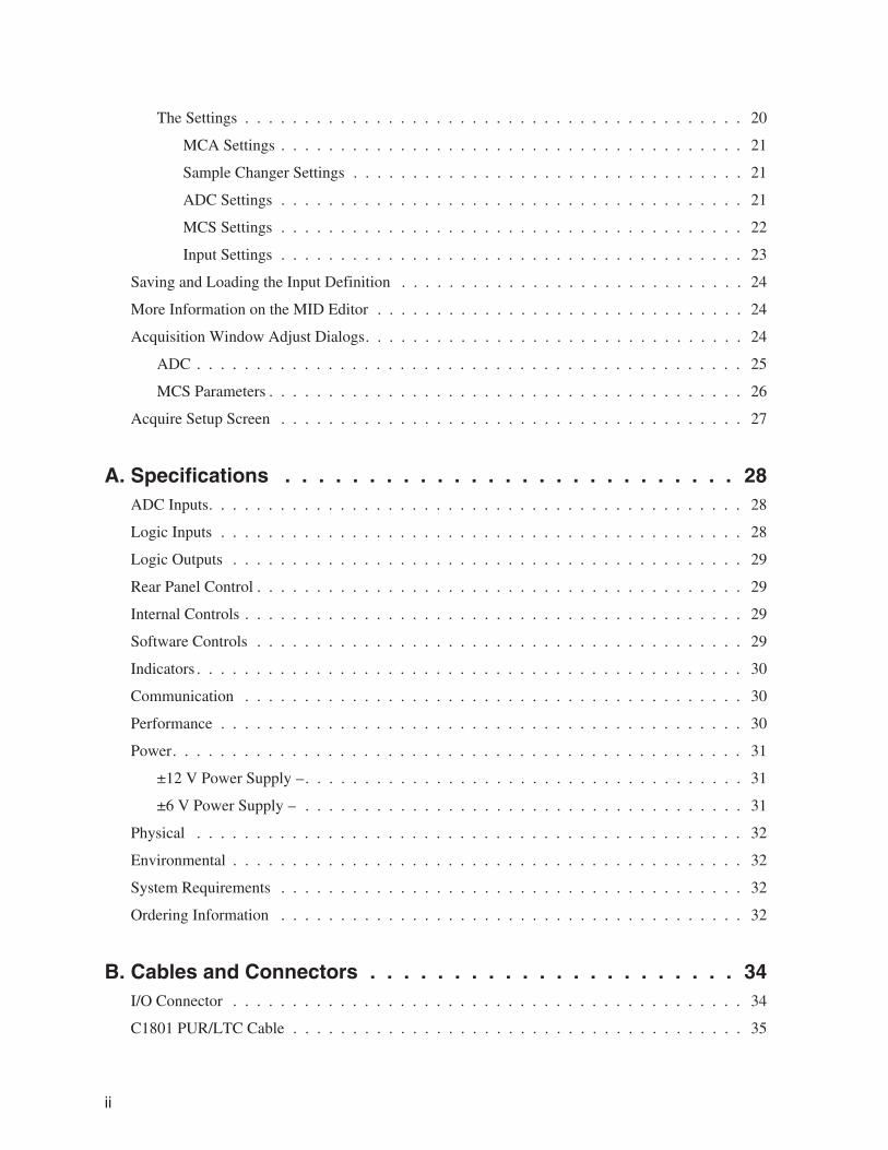
Front PanelThis is a brief description of the Multiport II’s front panel indicators and connectors.For more detailed information, refer to Appendix A, Specifications.
3
Front Panel
Figure 1 Front Panel Indicators and Connectors
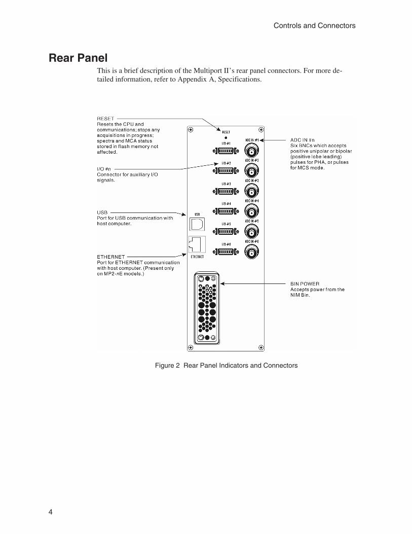
Rear PanelThis is a brief description of the Multiport II’s rear panel connectors. For more de-tailed information, refer to Appendix A, Specifications.
4
Controls and Connectors
Figure 2 Rear Panel Indicators and Connectors
Internal Controls and Connectors
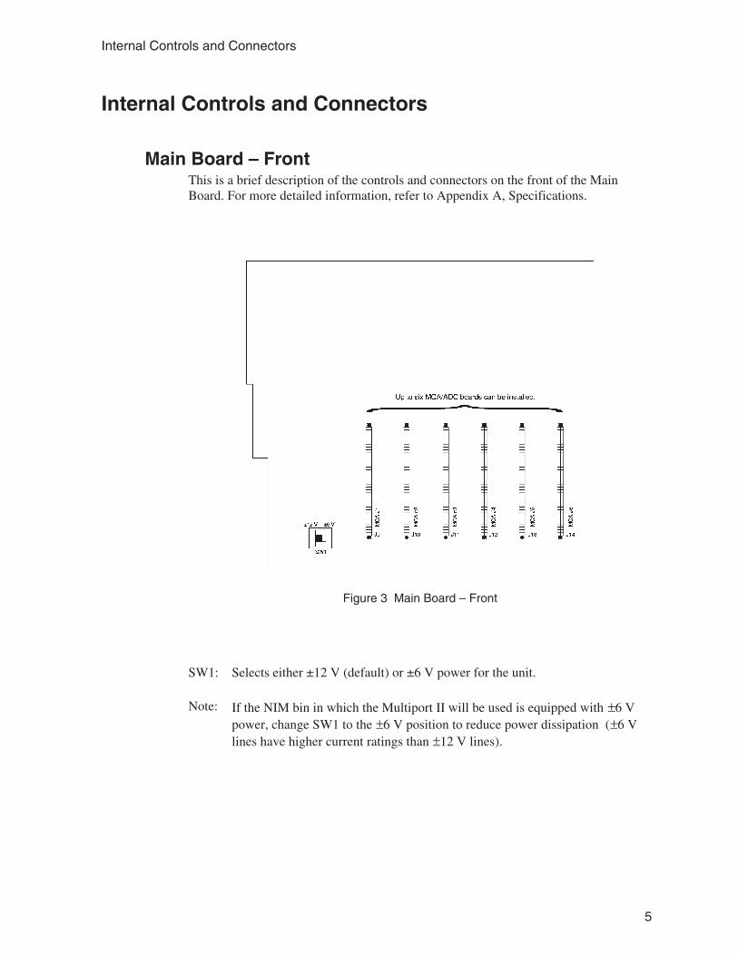
Main Board – FrontThis is a brief description of the controls and connectors on the front of the MainBoard. For more detailed information, refer to Appendix A, Specifications.
SW1: Selects either ±12 V (default) or ±6 V power for the unit.
Note: If the NIM bin in which the Multiport II will be used is equipped with ±6 Vpower, change SW1 to the ±6 V position to reduce power dissipation (±6 Vlines have higher current ratings than ±12 V lines).
5
Internal Controls and Connectors
Figure 3 Main Board – Front

Main Board – RearThis is a brief description of the controls and connectors on the rear of the MainBoard. For more detailed information, refer to Appendix A, Specifications.
SW2: This switch, if installed, is for Factory Diagnostics only; all switches must beleft in the OFF position.
J7: This jumper is for Factory Use Only; do not connect anything to it.
6
Controls and Connectors
Figure 4 Main Board – Rear
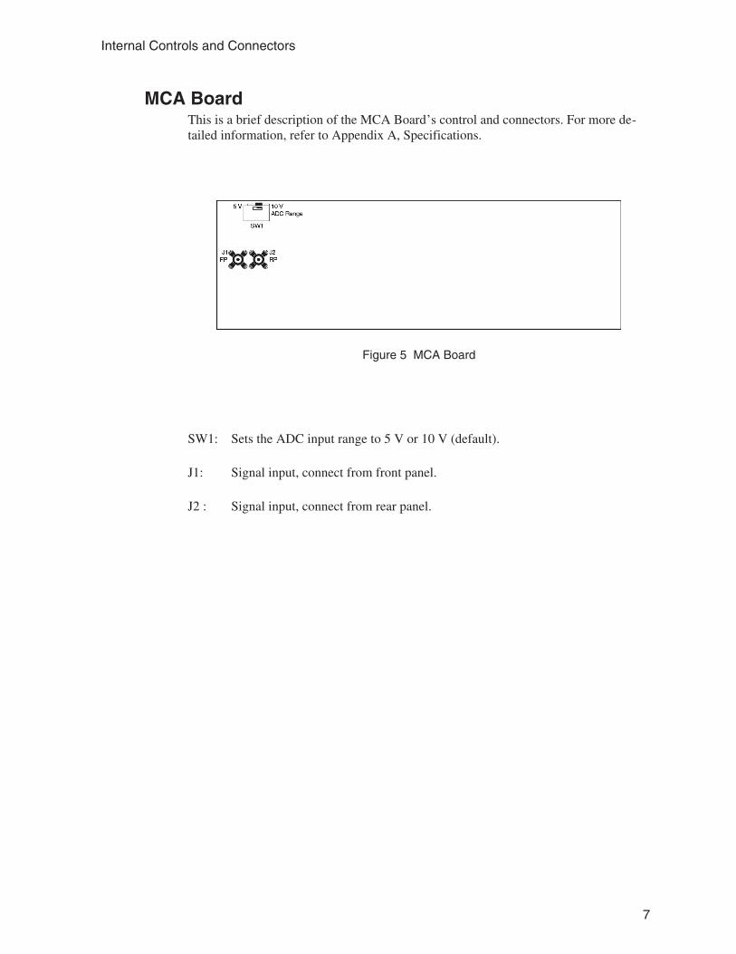
MCA BoardThis is a brief description of the MCA Board’s control and connectors. For more de-tailed information, refer to Appendix A, Specifications.
SW1: Sets the ADC input range to 5 V or 10 V (default).
J1: Signal input, connect from front panel.
J2 : Signal input, connect from rear panel.
7
Internal Controls and Connectors
Figure 5 MCA Board

3. Setup and Configuration
This chapter will guide you through to connecting and setting up the system.
InstallationThe Canberra Model 2100 Bin and Power Supply, or other bin and power supply sys-tems conforming to the mechanical and electrical standards set by DOE/ER-00457Twill accommodate the Multiport II NIM module. The module’s right side cover acts asa guide for insertion of the instrument. The module is secured by turning the two frontpanel captive screws clockwise until finger tight. It is recommended that the NIM binpower switch be OFF whenever the module is installed or removed. To ensure safety,be sure to use a NIM Bin which complies with all applicable safety requirements.
The Multiport II can be operated where the ambient air temperature is between 0°Cand +50°C (+120°F maximum). Perforations in the top and bottom sides permit cool-ing air to circulate through the module. When relay rack mounted along with otherheat generating equipment, adequate clearance should be provided to allow for suffi-cient air flow through both the perforated top and bottom covers of the NIM Bin.
Field Installing Additional BoardsEach Multiport II NIM module can accommodate up to six MCA/ADC boards. Addi-tional MCA/ADC boards can be field installed. Though the boards can be installed inany available slot, the recommended practice is to install them in numerical order.
To install additional MCA/ADC boards, follow these steps:
1. Turn off the NIM Bin’s power and remove the Multiport II NIM modulefrom the Bin.
2. Remove both of the Multiport II’s side covers.
3. When the Multiport II is shipped, each pair of unused signal cables, one fromthe rear panel and one from the front panel, is tied to each slot’s card guides.Before installing a board, you’ll have to cut and remove the cable tie from aboard slot.
4. Plugthe front panel signal cable into the board’s J1 connector and the rearpanel signal cable into the J2 connector. Refer to Figure 5, MCA Board, onpage 7 for connector locations.
8
Setup and Configuration

5. Slide the MCA/ADC board into the slots in the board guides. Make sure thatthe multi-pin connector on the edge of the board is aligned with the matingconnector on the main board.
6. Press the MCA/ADC board in, while supporting the main board from thebottom to prevent excessive flexing. The board is properly inserted when itstop edge does not protrude above the board guides.
7. Repeat steps 3–6 for each additional board being installed.
8. Replace the Multiport II’s side covers.
9. Insert the Multiport II into the NIM Bin, turn on the Bin’s power and verifythat the Multiport II is functioning correctly.
Connecting the SystemEach of the installed MCA boards can be connected to an amplifier output signal.Connect the amplifier signal to the board’s front or rear ADC IN connector.
Connecting to the Host ComputerThe Multiport II supports two computer interface systems; high speed USB 1.1 andEthernet. Connect the Multiport II to the host computer using the USB or Ethernet in-terface as described below. Refer to Appendix D, Software Installation, and AppendixE, Configuring the Ethernet Option, for instructions on how to install/configure theUSB or Ethernet communications.
Connecting the USB CableThe USB cable allows transfer of computer commands and spectral data between theMultiport II and the host computer. Both ends have USB connectors which are definedby the USB standard; one end is rectangular, the other end is square. Connect thesquare end to the USB port located on the rear panel of the Multiport II, connect therectangular end to the USB port on the host computer.
Note: The Multiport II ships with a 3 m (10 ft) USB cable. A maximum cable lengthof up to 5 m (16 ft) may be used.
9
Connecting the System

Connecting the Ethernet CableThe Multiport II connects to the local network using a standard RJ-45 (8-pin) patch ca-ble. The Multiport II may be used by any computer on the local network. TheMultiport II’s IP Address or Device name is assigned using the Multiport_II_Ether-net_Configuration.exe program. Refer to Appendix E, Configuring the Ethernet Op-tion, for complete instructions on using the configuration program.
MID DefinitionBefore the Multiport II can be used with Genie-2000, the communication interfacemust be defined and configured in the Genie-2000 MCA Input Definition (MID) Edi-tor.
• When using Ethernet, the Multiport II’s Network (IP) Address or Device Namemust be entered into the MID Configuration. Prior to that, the Multiport II’sEthernet port has to be enabled by using the Mulitport II’s USB connection (seeAppendix D, Software Installation).
• When using USB, the Multiport II’s serial number must be entered into theMID Configuration to allow the Genie-2000 software to identify the specificMultiport II instrument.
If this has not already been done please refer to “The MID Wizard” on page 11 forinstruction on defining the Multiport II MID input definition for USB or Ethernetoperation.
10
Setup and Configuration
4. User Interface and Controls
This chapter provides basic information on the user interface and functional operationof the setup control for the Multiport II.
Creating an MCA Input DefinitionAfter you’ve set up and connected your system, the first step in using your MultiportII is to create an MCA Input Definition (MID) for each MCA board.
For most cases, you’ll use the MID Wizard to help you set up your Multiport II’s InputDefinition quickly and easily.
If your Input Definition is more complex than the MID Wizard was designed to handleyou’ll need to use the MID Editor (page 14) to create your definition. The MID Editoris also used to change (edit) an existing definition.
The MID WizardTo use the MID Wizard, open the Genie-2000 folder and select the MID Wizard iconto start the definition process.
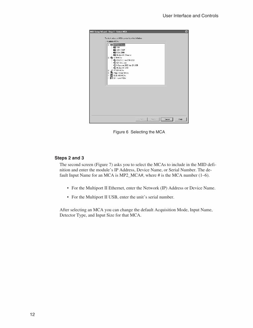
Step 1The first screen (Figure 6) lets you select the MCA you want to define. Select eitherMultiport II Ethernet from the “Network MCAs” list or Multiport II USB from the“USB MCAs” list.
11
Creating an MCA Input Definition
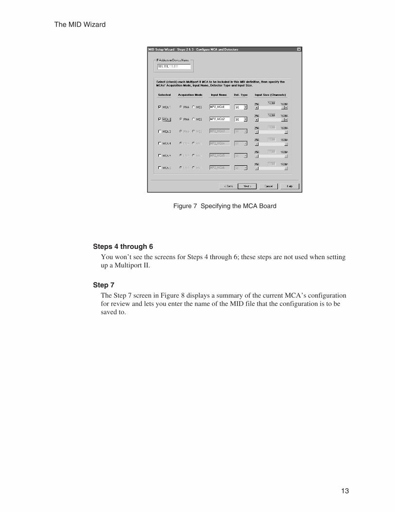
Steps 2 and 3The second screen (Figure 7) asks you to select the MCAs to include in the MID defi-nition and enter the module’s IP Address, Device Name, or Serial Number. The de-fault Input Name for an MCA is MP2_MCA#, where # is the MCA number (1–6).
• For the Multiport II Ethernet, enter the Network (IP) Address or Device Name.
• For the Multiport II USB, enter the unit’s serial number.
After selecting an MCA you can change the default Acquisition Mode, Input Name,Detector Type, and Input Size for that MCA.
12
User Interface and Controls
Figure 6 Selecting the MCA
Steps 4 through 6You won’t see the screens for Steps 4 through 6; these steps are not used when settingup a Multiport II.
Step 7The Step 7 screen in Figure 8 displays a summary of the current MCA’s configurationfor review and lets you enter the name of the MID file that the configuration is to besaved to.
13
The MID Wizard
Figure 7 Specifying the MCA Board
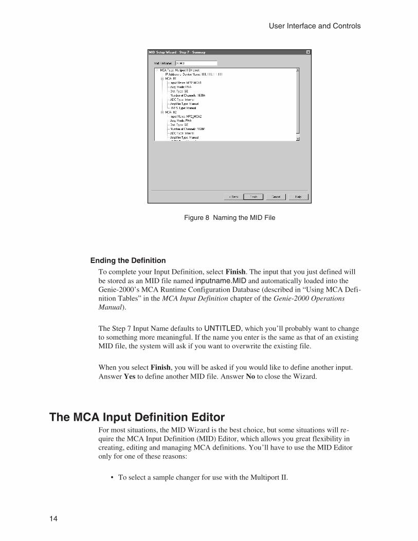
Ending the DefinitionTo complete your Input Definition, select Finish. The input that you just defined willbe stored as an MID file named inputname.MID and automatically loaded into theGenie-2000’s MCA Runtime Configuration Database (described in “Using MCA Defi-nition Tables” in the MCA Input Definition chapter of the Genie-2000 OperationsManual).
The Step 7 Input Name defaults to UNTITLED, which you’ll probably want to changeto something more meaningful. If the name you enter is the same as that of an existingMID file, the system will ask if you want to overwrite the existing file.
When you select Finish, you will be asked if you would like to define another input.Answer Yes to define another MID file. Answer No to close the Wizard.
The MCA Input Definition EditorFor most situations, the MID Wizard is the best choice, but some situations will re-quire the MCA Input Definition (MID) Editor, which allows you great flexibility increating, editing and managing MCA definitions. You’ll have to use the MID Editoronly for one of these reasons:
• To select a sample changer for use with the Multiport II.
14
User Interface and Controls
Figure 8 Naming the MID File
• To change input Settings such as detector type.
• To choose between PHA and MCS modes.
• To change the default ADC settings.
Note: You can not change the MCS Settings using the MID Editor.
The editing procedure is described in “Editing an MCA Definition” in the MCA InputDefinition chapter of the Genie-2000 Operations Manual. That chapter also hasdetailed information on using the MID Editor.
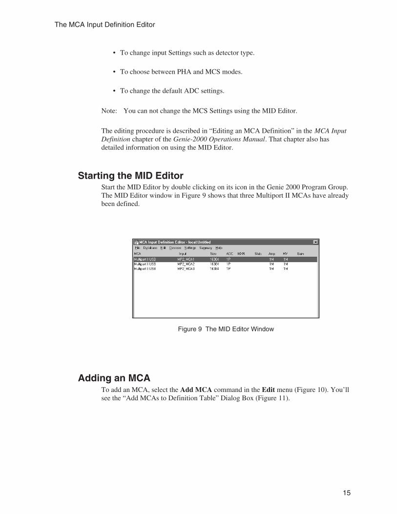
Starting the MID EditorStart the MID Editor by double clicking on its icon in the Genie 2000 Program Group.The MID Editor window in Figure 9 shows that three Multiport II MCAs have alreadybeen defined.
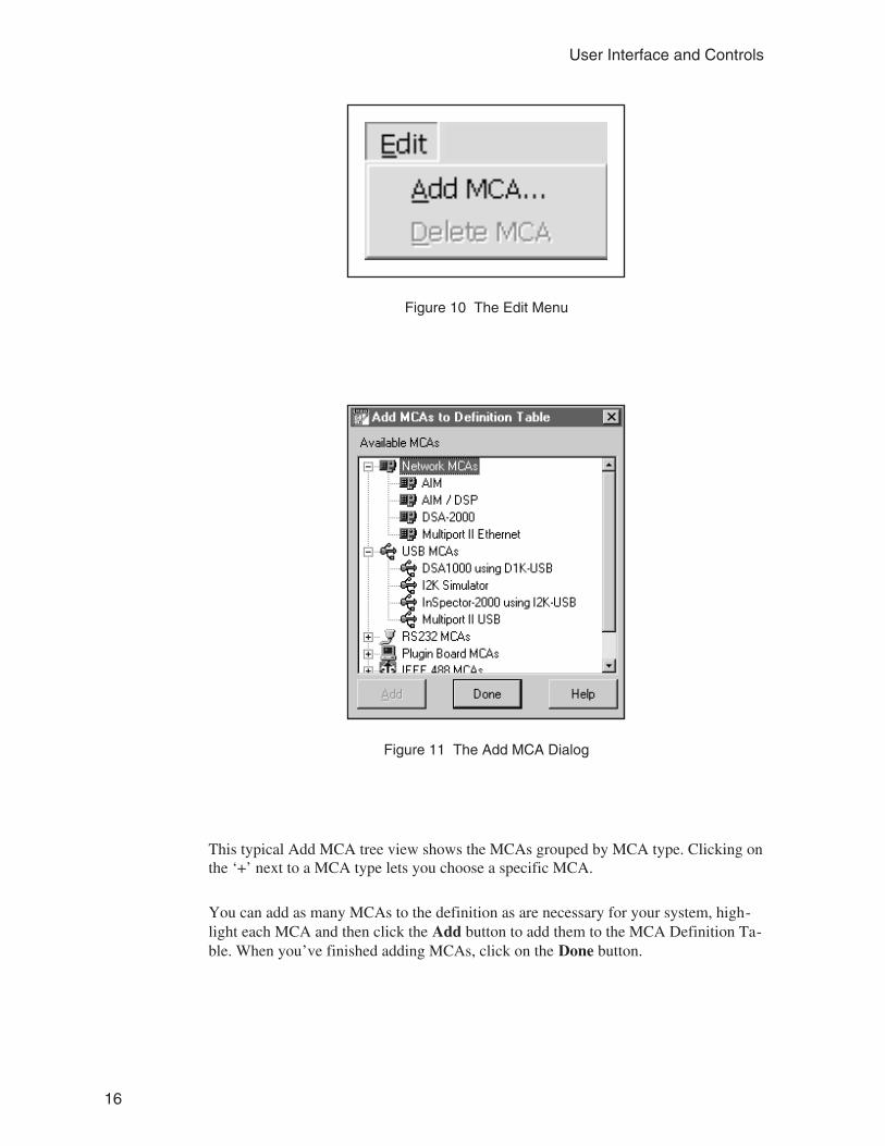
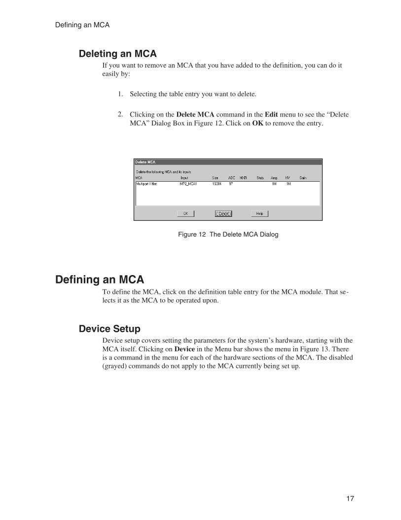
Adding an MCATo add an MCA, select the Add MCA command in the Edit menu (Figure 10). You’llsee the “Add MCAs to Definition Table” Dialog Box (Figure 11).
15
The MCA Input Definition Editor
Figure 9 The MID Editor Window
This typical Add MCA tree view shows the MCAs grouped by MCA type. Clicking onthe ‘+’ next to a MCA type lets you choose a specific MCA.
You can add as many MCAs to the definition as are necessary for your system, high-light each MCA and then click the Add button to add them to the MCA Definition Ta-ble. When you’ve finished adding MCAs, click on the Done button.
16
User Interface and Controls
Figure 10 The Edit Menu
Figure 11 The Add MCA Dialog
Deleting an MCAIf you want to remove an MCA that you have added to the definition, you can do iteasily by:
1. Selecting the table entry you want to delete.
2. Clicking on the Delete MCA command in the Edit menu to see the “DeleteMCA” Dialog Box in Figure 12. Click on OK to remove the entry.
Defining an MCATo define the MCA, click on the definition table entry for the MCA module. That se-lects it as the MCA to be operated upon.
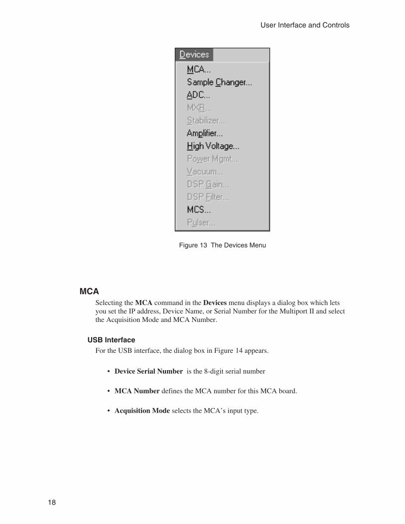
Device SetupDevice setup covers setting the parameters for the system’s hardware, starting with theMCA itself. Clicking on Device in the Menu bar shows the menu in Figure 13. Thereis a command in the menu for each of the hardware sections of the MCA. The disabled(grayed) commands do not apply to the MCA currently being set up.
17
Defining an MCA
Figure 12 The Delete MCA Dialog
MCASelecting the MCA command in the Devices menu displays a dialog box which letsyou set the IP address, Device Name, or Serial Number for the Multiport II and selectthe Acquisition Mode and MCA Number.
USB InterfaceFor the USB interface, the dialog box in Figure 14 appears.
• Device Serial Number is the 8-digit serial number
• MCA Number defines the MCA number for this MCA board.
• Acquisition Mode selects the MCA’s input type.
18
User Interface and Controls
Figure 13 The Devices Menu
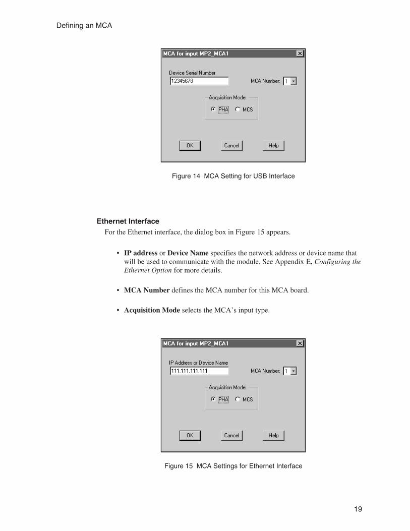
Ethernet InterfaceFor the Ethernet interface, the dialog box in Figure 15 appears.
• IP address or Device Name specifies the network address or device name thatwill be used to communicate with the module. See Appendix E, Configuring theEthernet Option for more details.
• MCA Number defines the MCA number for this MCA board.
• Acquisition Mode selects the MCA’s input type.
19
Defining an MCA
Figure 14 MCA Setting for USB Interface
Figure 15 MCA Settings for Ethernet Interface
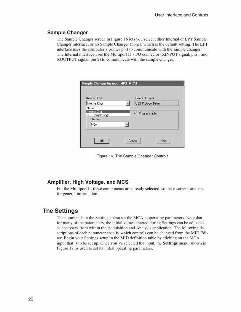
Sample ChangerThe Sample Changer screen in Figure 16 lets you select either Internal or LPT SampleChanger interface, or no Sample Changer (none), which is the default setting. The LPTinterface uses the computer’s printer port to communicate with the sample changer.The Internal interface uses the Multiport II’s I/O connector (XINPUT signal, pin 1 andXOUTPUT signal, pin 2) to communicate with the sample changer.
Amplifier, High Voltage, and MCSFor the Multiport II, these components are already selected, so these screens are usedfor general information.
The SettingsThe commands in the Settings menu set the MCA’s operating parameters. Note thatfor many of the parameters, the initial values entered during Settings can be adjustedas necessary from within the Acquisition and Analysis application. The following de-scriptions of each parameter specify which controls can be changed from the MID Edi-tor. Begin your Settings setup in the MID definition table by clicking on the MCAinput that is to be set up. Once you’ve selected the input, the Settings menu, shown inFigure 17, is used to set its initial operating parameters.
20
User Interface and Controls
Figure 16 The Sample Changer Controls
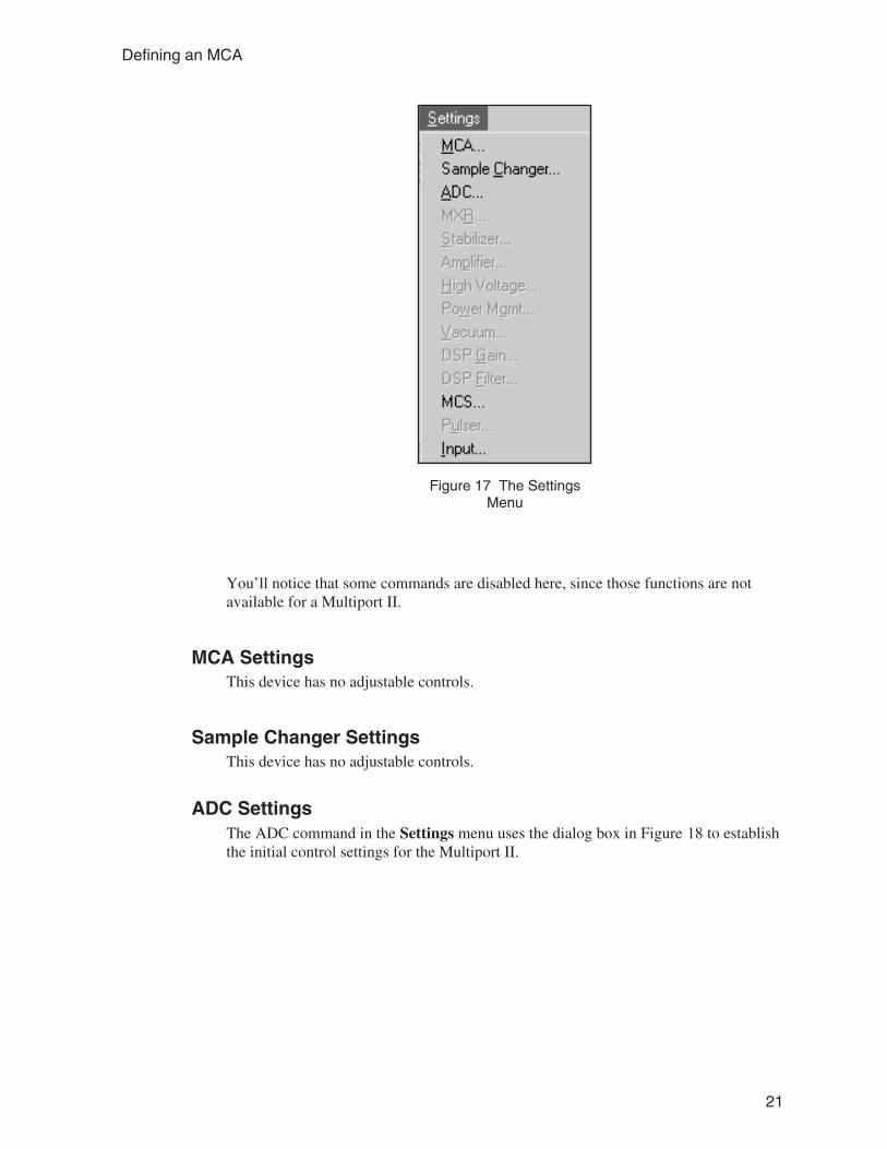
You’ll notice that some commands are disabled here, since those functions are notavailable for a Multiport II.
MCA SettingsThis device has no adjustable controls.
Sample Changer SettingsThis device has no adjustable controls.
ADC SettingsThe ADC command in the Settings menu uses the dialog box in Figure 18 to establishthe initial control settings for the Multiport II.
21
Defining an MCA
Figure 17 The SettingsMenu
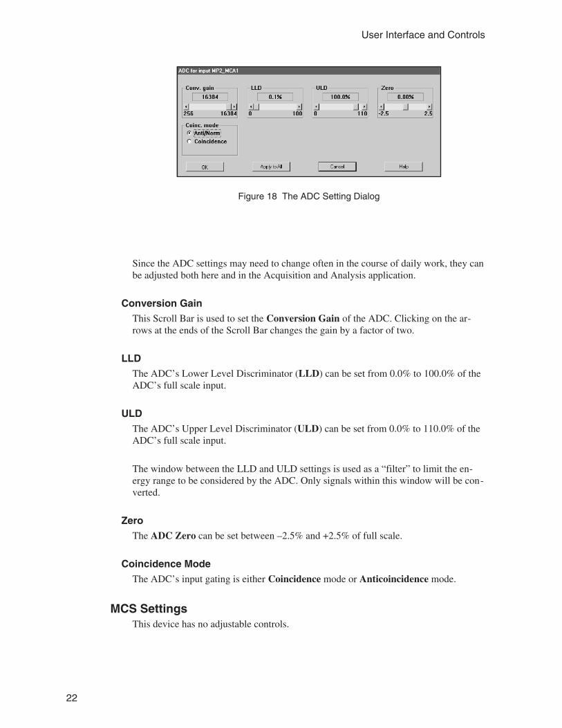
Since the ADC settings may need to change often in the course of daily work, they canbe adjusted both here and in the Acquisition and Analysis application.
Conversion GainThis Scroll Bar is used to set the Conversion Gain of the ADC. Clicking on the ar-rows at the ends of the Scroll Bar changes the gain by a factor of two.
LLDThe ADC’s Lower Level Discriminator (LLD) can be set from 0.0% to 100.0% of theADC’s full scale input.
ULDThe ADC’s Upper Level Discriminator (ULD) can be set from 0.0% to 110.0% of theADC’s full scale input.
The window between the LLD and ULD settings is used as a “filter” to limit the en-ergy range to be considered by the ADC. Only signals within this window will be con-verted.
ZeroThe ADC Zero can be set between –2.5% and +2.5% of full scale.
Coincidence ModeThe ADC’s input gating is either Coincidence mode or Anticoincidence mode.
MCS SettingsThis device has no adjustable controls.
22
User Interface and Controls
Figure 18 The ADC Setting Dialog
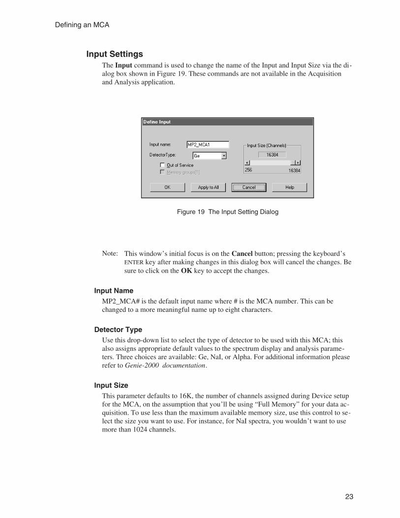
Input SettingsThe Input command is used to change the name of the Input and Input Size via the di-alog box shown in Figure 19. These commands are not available in the Acquisitionand Analysis application.
Note: This window’s initial focus is on the Cancel button; pressing the keyboard’sENTER key after making changes in this dialog box will cancel the changes. Besure to click on the OK key to accept the changes.
Input NameMP2_MCA# is the default input name where # is the MCA number. This can bechanged to a more meaningful name up to eight characters.
Detector TypeUse this drop-down list to select the type of detector to be used with this MCA; thisalso assigns appropriate default values to the spectrum display and analysis parame-ters. Three choices are available: Ge, NaI, or Alpha. For additional information pleaserefer to Genie-2000 documentation.
Input SizeThis parameter defaults to 16K, the number of channels assigned during Device setupfor the MCA, on the assumption that you’ll be using “Full Memory” for your data ac-quisition. To use less than the maximum available memory size, use this control to se-lect the size you want to use. For instance, for NaI spectra, you wouldn’t want to usemore than 1024 channels.
23
Defining an MCA
Figure 19 The Input Setting Dialog
Out of ServiceThis check box allows you to place this Input temporarily “out of service”. That is, itwill remain as an entry in your MCA Definition File but will not be available for dataacquisition. It is meant to be used when the MCA or its front end electronics are tem-porarily disconnected.
Memory GroupsIs always 1 memory group.
Saving and Loading the Input DefinitionHaving completed a definition, the next step is to save it in a disk file so it can be usedin the future. From the File menu the command Save As saves the definition to a userdefined MID file and the command Save saves the settings to an exisiting MID file.
After having saved the definition, the next step is to load it into the run-time databaseso that it can be used by the Genie2000 applications. Use the Load To command inthe Database menu to load the definition.
Refer to the MCA Input Definition chapter of the Genie 2000 Operations Manual foradditional information regarding saving and loading definition files, as well as editingexisting files.
More Information on the MID EditorYou can find information on Changing the Editor’s Summary View, Editing an MCADefinition and Using MCA Definition Tables in the MCA Input Definition chapter ofthe Genie-2000 Operations Manual.
Acquisition Window Adjust DialogsThe MCA Adjust Screens, which are accessed from the Gamma Acquisition andAnalysis application’s Menu Bar, allow you to adjust the Multiport II’s programmablecontrols.
As adjustments are made in the dialog box, the new values are sent to the Multiport II.To save the adjustments to the datasource’s MID file, use the Gamma Acquisition andAnalysis application’s File | Save command so that the next time this datasource is se-lected, the proper setting will be loaded into the Multiport II.
24
User Interface and Controls
The Next and Prev(ious) buttons at the left side of the Adjust screen are used to moveto the next (or previous) “page” of the controls when there are more control elementsthan will fit in the basic box.
To access the Adjust screens, a Multiport II datasource must have been opened. Toopen, select File | Open Datasource, then select “Detector” in the Type box. Next, se-lect the datasource file and click on open.
Each of the following sections describes one of the Multiport II parameters that can bechanged in the Gamma Acquisition and Analysis (GAA) application’s Adjust dialog.To change a parameter, click on MCA | Adjust in the GAA application’s Main Menu,then select the radio button for the parameter you want to change.
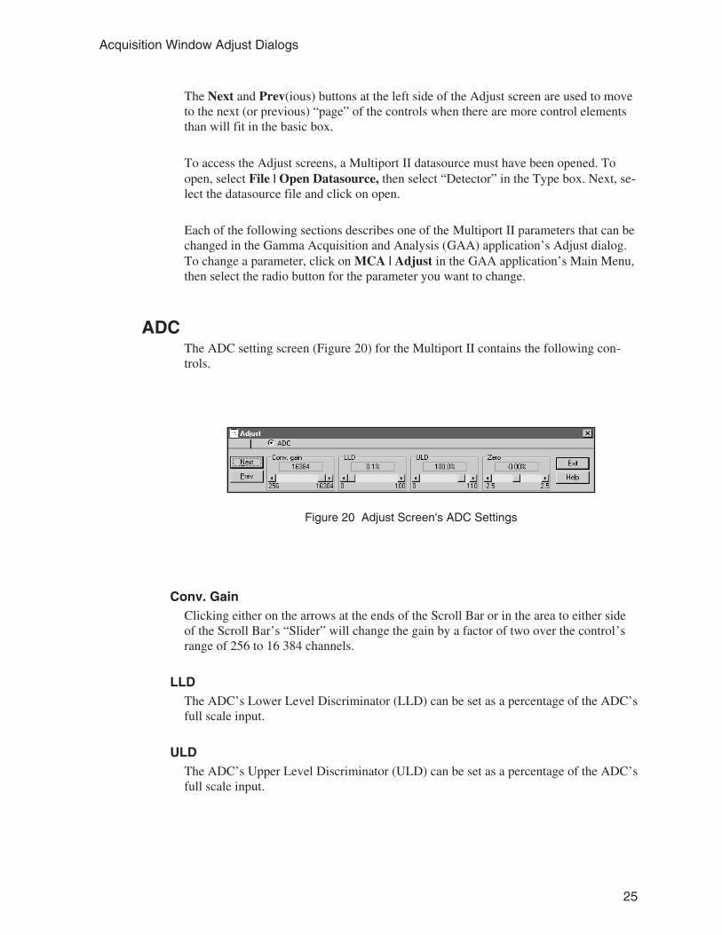
ADCThe ADC setting screen (Figure 20) for the Multiport II contains the following con-trols.
Conv. GainClicking either on the arrows at the ends of the Scroll Bar or in the area to either sideof the Scroll Bar’s “Slider” will change the gain by a factor of two over the control’srange of 256 to 16 384 channels.
LLDThe ADC’s Lower Level Discriminator (LLD) can be set as a percentage of the ADC’sfull scale input.
ULDThe ADC’s Upper Level Discriminator (ULD) can be set as a percentage of the ADC’sfull scale input.
25
Acquisition Window Adjust Dialogs
Figure 20 Adjust Screen's ADC Settings
ZeroThe ADC’s Zero is factory set for each conversion gain, so that a Zero setting of 0%corresponds to zero intercept (zero energy input stores in channel 1, the first channelused for spectral data storage) for that conversion gain. The Zero control can be usedto change the zero intercept to another channel.
Coinc. ModeSets the coincidence mode for the extended Gate signal, when external gating is used.
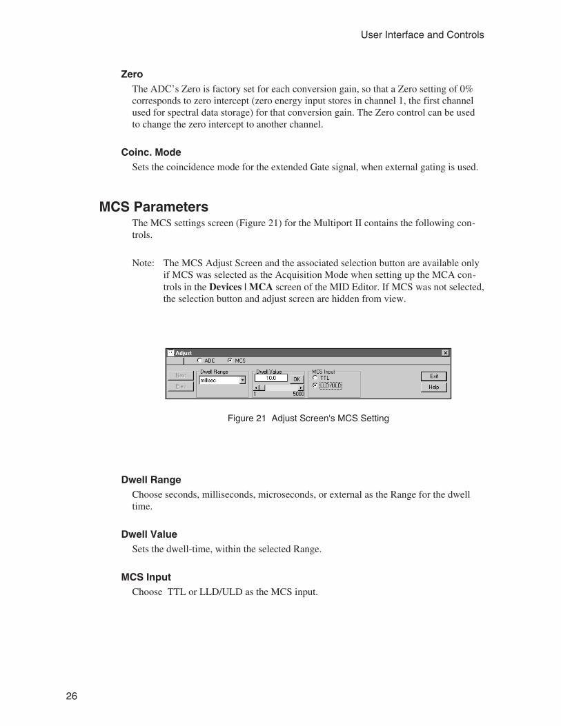
MCS ParametersThe MCS settings screen (Figure 21) for the Multiport II contains the following con-trols.
Note: The MCS Adjust Screen and the associated selection button are available onlyif MCS was selected as the Acquisition Mode when setting up the MCA con-trols in the Devices | MCA screen of the MID Editor. If MCS was not selected,the selection button and adjust screen are hidden from view.
Dwell RangeChoose seconds, milliseconds, microseconds, or external as the Range for the dwelltime.
Dwell ValueSets the dwell-time, within the selected Range.
MCS InputChoose TTL or LLD/ULD as the MCS input.
26
User Interface and Controls
Figure 21 Adjust Screen's MCS Setting
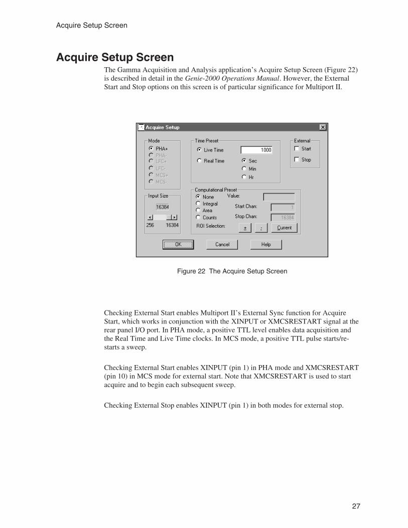
Acquire Setup ScreenThe Gamma Acquisition and Analysis application’s Acquire Setup Screen (Figure 22)is described in detail in the Genie-2000 Operations Manual. However, the ExternalStart and Stop options on this screen is of particular significance for Multiport II.
Checking External Start enables Multiport II’s External Sync function for AcquireStart, which works in conjunction with the XINPUT or XMCSRESTART signal at therear panel I/O port. In PHA mode, a positive TTL level enables data acquisition andthe Real Time and Live Time clocks. In MCS mode, a positive TTL pulse starts/re-starts a sweep.
Checking External Start enables XINPUT (pin 1) in PHA mode and XMCSRESTART(pin 10) in MCS mode for external start. Note that XMCSRESTART is used to startacquire and to begin each subsequent sweep.
Checking External Stop enables XINPUT (pin 1) in both modes for external stop.
27
Acquire Setup Screen
Figure 22 The Acquire Setup Screen
A. Specifications
ADC InputsADC IN – Accepts positive unipolar or bipolar, positive lobe leading, pulses for PHAand MCS, LLD/ULD selected for Internal Pulse Source; amplitude 0 to +10 V or 0 to+5 V, switch selectable; rise time >0.25 µs; width >0.5 µs; Zin = 1.33 kΩ (10 V range)or 2 kΩ (5 V range); direct coupled; front and rear panel BNCs, one pair per MCA.
Logic InputsRear panel mini-D I/O connectors for logic input and output signals, one per MCA.
XINPUT – External start/stop and sample changer ready input; active high, active lowsetting; 10 kΩ pull-up to 5 V; TTL pulse; pin 1 of the I/O connector.
XSUSPEND – Suspends pulse processing and preset counters; fixed active low; 10 kΩpull-up to +5 V; TTL pulse; pin 3 of the I/O connector.
XDT – PUR dead time input; active high, active low setting; forced to inactive state by1 kΩ pull-up to +5 V or pull-down to GND when no signal is present; TTL pulse; pin5 of the I/O connector.
XMCSRESTART – MCS sweep advance input; active high, active low setting; edgetriggered; 10 kΩ pull-up to +5 V; TTL pulse; pin 10 of the I/O connector.
XMCSADVANCE – External channel advance input; active high, active low setting;edge triggered; duration ≥10 ns; max. rate 1 MHz; 10kΩ pull-up to +5 V; positiveTTL pulse; pin 11 of the I/O connector.
XMCSPULSE – MCS input; active high, active low setting; edge triggered; duration≥10 ns; rate ≤ 10 MHz; 10 kΩ pull-up to +5 V; positive TTL pulse; pin 12 of the I/Oconnector.
XCOINC – Coincidence/Anticoincidence input; active high, active low setting; edgetriggered, level sensitive selection; forced to inactive state by 1 kΩ pull-up to +5 V orpull-down to GND when no signal is present; TTL pulse; pin 13 of the I/O connector.
XREJ – Pileup reject input; must occur during the ADC linear gate (LG) time activehigh, active low setting; forced to inactive state by 1 kΩ pull-up to +5 V or pull-downto GND when no signal is present; positive TTL pulse; pin 14 of the I/O connector.
28
Specifications
Logic OutputsRear panel mini-D I/O connectors for logic input and output signals, one per MCA.
XOUTPUT – Advance sample changer output; active high, active low setting; 150 msTTL pulse; pin 2 of the I/O connector.
XSCA – Single channel analyzer output; ≈250 ns TTL pulse generated for input pulsesdetected between LLD and ULD; active high; pin 4 of the I/O connector.
XLG – PUR linear gate output; active when ADC acquires an input pulse; active high,active low setting; TTL pulse; pin 6 of the I/O connector.
XCOLLECTSTATUS – External acquire status; active high, active low setting; TTLpulse; pin 9 of the I/O connector.
+5 V – Power output for external circuitry; 100 mA max. per connector; pin 7 of theI/O connector.
Rear Panel ControlRESET – Resets the CPU and communication; stops any acquisition in progress; spec-tra and MCA status stored in flash memory not affected; rear panel pushbutton.
Internal ControlsADC INPUT RANGE – Sets the ADC input range to 0–10 V (default) or 0–5 V; slideswitch on the MCA board.
POWER SUPPLY VOLTAGE – Selects either ±12 V (default) or ±6 V; slide switchon the main board.
Software ControlsADC LLD – 0 to 100% of full scale (4096 steps).
ADC ULD – 0 to 110% of full scale (4096 steps).
ADC ZERO – ±2.5% of full scale (4096 steps).
29
Logic Outputs
ADC CONVERSION GAIN – 256, 512, 1024, 2048, 4096, 8192, 16 384.
REAL TIME PRESET – Maximum of ≈49.71 days.
LIVE TIME PRESET – Maximum of ≈49.71 days.
IndicatorsMCA #n – ON when MCA board in slot #n is installed and power in ON; front panelgreen LED.
ACQUIRE – ON when the corresponding MCA is acquiring; front panel green LED.
RATE – Flashes for every input pulse processed in the corresponding MCA; frontpanel yellow LED.
COMM – ON when unit is ready for USB and/or Ethernet communication; flashesbrighter when data transfer occurs; front panel yellow LED.
CommunicationUSB – Standard USB port; rear panel USB type-B connector.
ETHERNET – Optional Ethernet port; rear panel RJ-45 connector.
PerformanceINTEGRAL NONLINEARITY – <±0.025% of full scale over the top 99.5% of se-lected range.
DIFFERENTIAL NONLINEARITY – <±0.9% of full scale over the top 99.5% ofrange including effects from differential nonlinearity.
GAIN DRIFT – <±0.005% of full scale/oC.
ZERO DRIFT – <±0.005% of full scale/oC.
LONG TERM DRIFT – <±0.005% of full scale/24 h at a constant temperature.
30
Specifications

PEAK SHIFT – <±0.025% of full scale at rates up to 100 kHz.
ADC DEAD TIME – Linear gate time +1.2 µs.
CHANNEL PROFILE – Typically flat over 90% of channel width.
MCS –
INPUT RATE – Up to 10 MHz.
DWELL TIME – Software selectable from 1 µs to ≈71 min, with varying resolu-tion in increments of 1 µs.
SWEEP SELECTION – Software selectable preset sweeps from 1 to 232–1.
DEAD TIME – Between channels: 0. Between sweeps: 0 for internal sweep restart,0–40 ns for external sweep restart.
NUMBER OF CHANNELS – 16 384.
COUNTS/CHANNEL – 232–1.
PowerDepends on the setting of the internal control for Power Supply Voltage (±12 V or ±6V):
±12 V Power Supply –One MCA board:
+12 V – 250 mA –12 V – 50 mA
Each additional MCA board:
+12 V – 90 mA –12 V – 50 mA
±6 V Power Supply –One MCA board:
+6 V – 475 mA –6 V – 50 mA
31
Power
Each additional MCA board:
+6 V – 150 mA –6 V – 50 mA
PhysicalSIZE – Standard double width NIM module 6.86 x 22.12 cm (2.70 x 8.71 in.) perDOE/ER-0457T.
NET WEIGHT – 1.36 kg (3.0 lb) with one MCA/ADC board.
EnvironmentalOPERATING TEMPERATURE – 0–45 oC.
OPERATING HUMIDITY – 0–80% relative, non-condensing.
Meets the environmental conditions specified by EN 61010, Installation Category I,Pollution Degree 2.
System RequirementsA PC-based system with a USB port. Ethernet version also requires Ethernet connec-tion.
Model S500 Genie 2000 Basic Spectroscopy Software, V2.1a or later.
Ordering InformationMP2-nU – Multiport II USB module with n inputs, where n is 1 to 6; not fieldungradable to the Ethernet module; includes one 3 m (10 ft) shielded USB cable.
MP2-nE – Multiport II Ethernet/USB module with n inputs, where n is 1 to 6; includesone 3 m (10 ft) shielded USB cable.
MPT2-MCA – One additional Multiport II MCA/ADC board.
C1801 – Multiport II PUR/LTC Cable (included with each MCA/ADC board).
32
Specifications

C1802 – Multiport II PUR/LTC Start/Stop and Sample Changer Cable.
C1804 – Multiport II PUR/LTC and MCS Start/Stop Cable.
33
Ordering Information

B. Cables and Connectors
I/O Connector
Pin Signal Description
1 XINPUT TTL Input. Can be used for External Start, External Stop, or toMonitor for Sample Changer Ready.
2 XOUTPUT TTL Output. Software Settable. Can be used to Advance Sam-ple Changer.
3 XSUSPEND TTL Input. Suspends pulse processing and preset counters.
4 XSCA Single Channel Analyzer Output.
5 XDT TTL Input. PUR Dead Time Signal. Hardware will force to itsinactive state when no signal is hooked up.
6 XLG TTL Output. PUR Linear Gate Signal.
7 +5 V Fused 5 V output, 100 mA max.
8 GND
9 XCOLLECTSTATUS TTL Output. Active while collecting.
10 XMCSRESTART TTL Input. Used during MCS Multisweep collections to syn-chronize the start of each sweep with an external event.
11 XMCSADV TTL Input. Used for MCS External Channel Advance instead ofDwell Counter.
12 XMCSPULSE TTL Input. If enabled, provides Pulses for MCS collection.
13 XCOINC Coincidence Input. Edge Triggered, Level Sensitive Setting.Anticoincidence, Coincidence Setting. Hardware will force toits active state when no signal is hooked up
14 XREJ TTL Input. PUR Reject. Hardware will force to its inactive statewhen no signal is hooked up.
34
Cables and Connectors
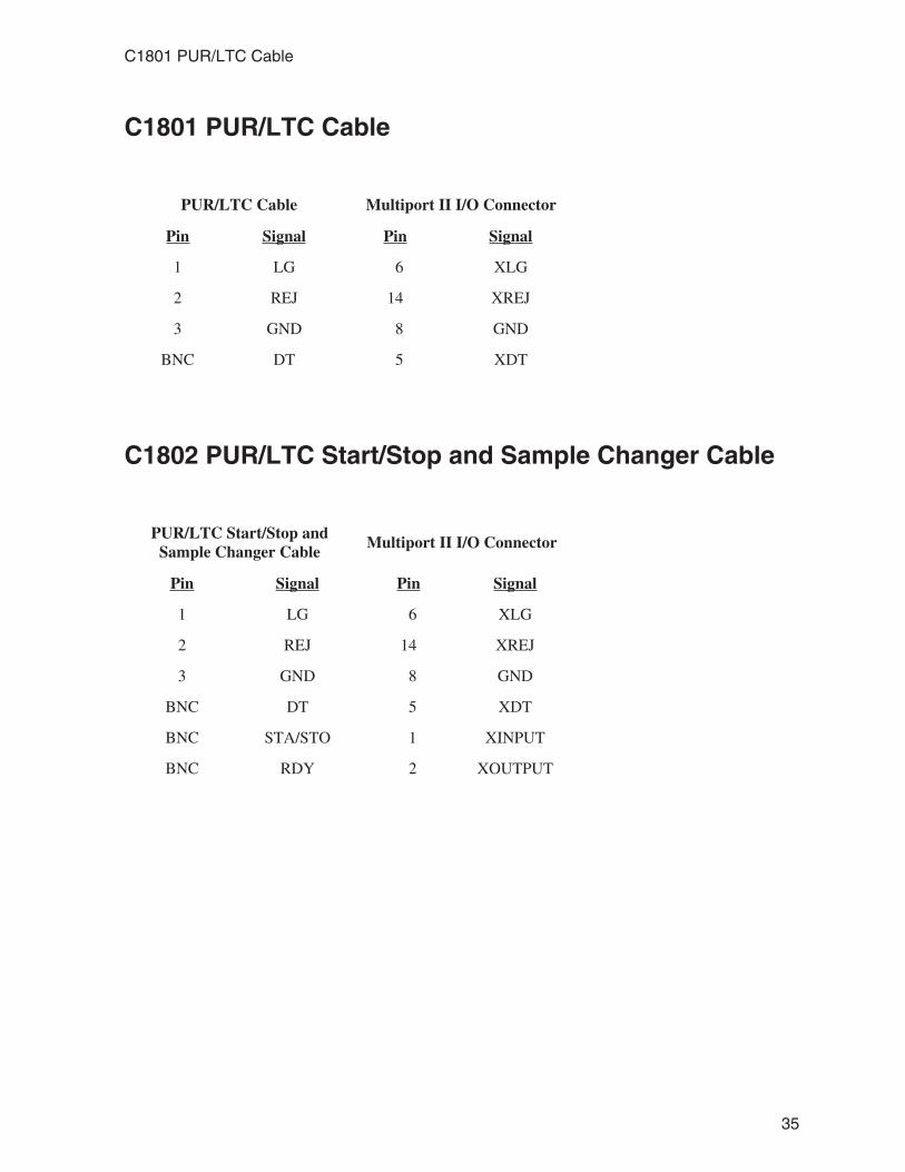
C1801 PUR/LTC Cable
PUR/LTC Cable Multiport II I/O Connector
Pin Signal Pin Signal
1 LG 6 XLG
2 REJ 14 XREJ
3 GND 8 GND
BNC DT 5 XDT
C1802 PUR/LTC Start/Stop and Sample Changer Cable
PUR/LTC Start/Stop andSample Changer Cable
Multiport II I/O Connector
Pin Signal Pin Signal
1 LG 6 XLG
2 REJ 14 XREJ
3 GND 8 GND
BNC DT 5 XDT
BNC STA/STO 1 XINPUT
BNC RDY 2 XOUTPUT
35
C1801 PUR/LTC Cable
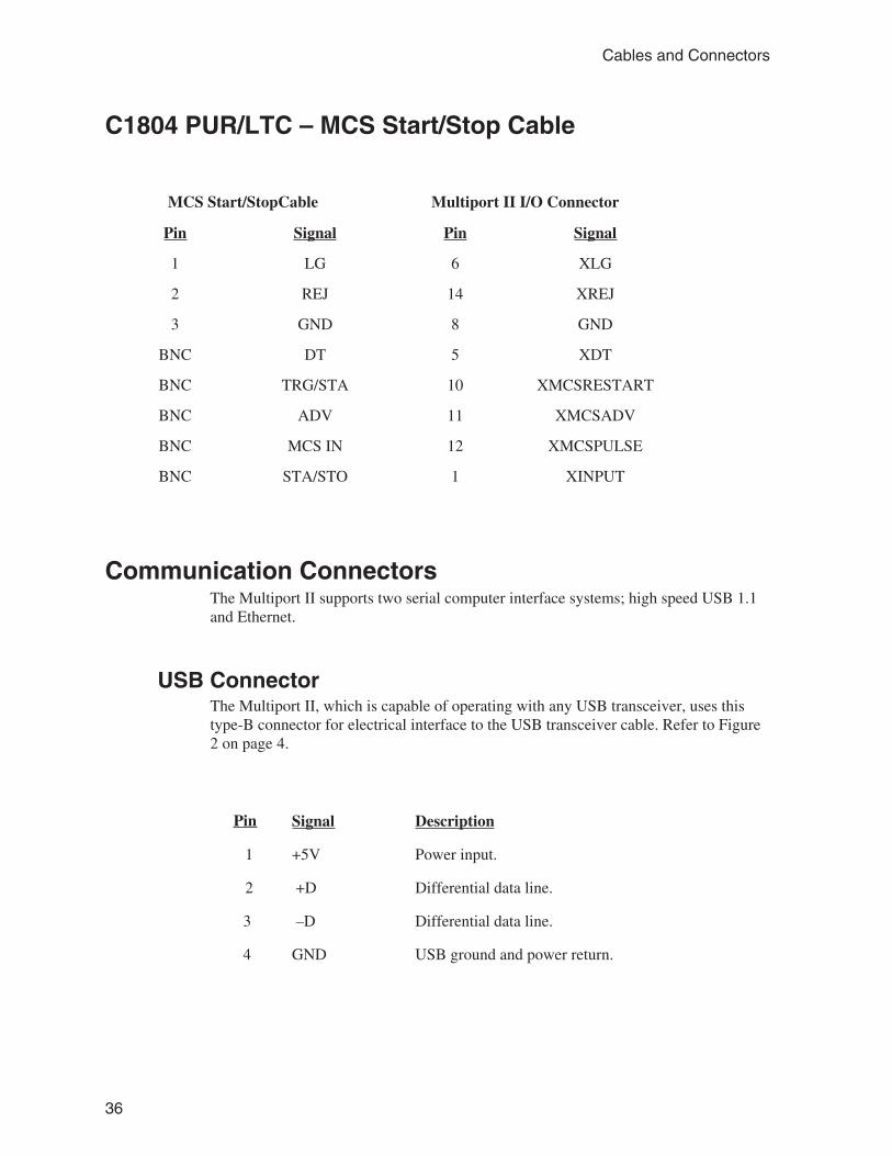
C1804 PUR/LTC – MCS Start/Stop Cable
MCS Start/StopCable Multiport II I/O Connector
Pin Signal Pin Signal
1 LG 6 XLG
2 REJ 14 XREJ
3 GND 8 GND
BNC DT 5 XDT
BNC TRG/STA 10 XMCSRESTART
BNC ADV 11 XMCSADV
BNC MCS IN 12 XMCSPULSE
BNC STA/STO 1 XINPUT
Communication ConnectorsThe Multiport II supports two serial computer interface systems; high speed USB 1.1and Ethernet.
USB ConnectorThe Multiport II, which is capable of operating with any USB transceiver, uses thistype-B connector for electrical interface to the USB transceiver cable. Refer to Figure2 on page 4.
Pin Signal Description
1 +5V Power input.
2 +D Differential data line.
3 –D Differential data line.
4 GND USB ground and power return.
36
Cables and Connectors

Ethernet ConnectorThe Multiport II, which is capable of operating with any IEEE 802.3-compliant Ether-net transceiver, uses this RJ45 connector for electrical interface to the Ethernet trans-ceiver cable. Refer to Figure 2 on page 4.
Pin Signal Description
1 TD+ Transmitted data to terminal.
2 TD– Transmitted data to terminal.
3 RD+ Received data from terminal.
4 NC No connection.
5 NC No connection.
6 RD- Received data from terminal.
7 NC No connection.
8 NC No connection.
37
Communication Connectors

C. Registry Variables
The Multiport II Parameters shown below cannot be modified directly within the Ge-nie Applications (e.g. GAA) using adjust controls. However, the predetermined pa-rameter values will be stored in the system registry and used to set the Multiport IIhardware accordingly. These parameters define hardware settings which are typicallynot modified in most Genie customer applications. However, those customers who doneed to modify these settings may change the values stored in the registry before start-ing the Genie Application. These parameters will be stored in registry key:“HKEY_LOCAL_MACHINE\SOFTWARE\Canberra Industries, Inc.\GENIE-2000Environment\Multiport II”.
Most of the parameters specify the “active” state of a particular input/output signal.Also specified is the state which the hardware internally pulls the signal when no ex-ternal signal is applied. In some cases the hardware pulls the signal High (+5), inwhich case the default value of Active Low (0 V) should be maintained when no sig-nal is applied. In other cases the hardware always pulls to the Inactive state as definedby the polarity setting.
The [default] specification defines this setting as the default value, which is the valueset in the registry when Genie is installed (i.e. the value unmodified by a customer).
Pin Signal Description Registry Settings
1 XINPUT Polarity of External Input - ExternalStart, Stop, or Sample Changer Ready.Pulled High (+5V) internally.
XinputPolarity:0 = Active Low (0V)1 = Active High (5V) [default]
2 XOUTPUT Polarity of Programmable Output -Sample Changer Advance signal.
XOutputPolarity:0 = Active Low (0V) [default]1 = Active High (5V)
3 XSUSPEND (in) External Suspend. Pulled High (+5) in-ternally.
Not programmable. Fixed Active Low.
4 XSCA (out) Single Channel Analyzer output. Not programmable. Fixed Active High.
5 XDT (in) Polarity of PUR Dead Time Correctionsignal. Pulled Inactive internally.
XAdcExtrnlDeadTPolarity:0 = Active Low (0V) [default]1 = Active High (5V)
6 XLG (out) Polarity of PUR Linear Gate Signal. XAdcExtrnlLGatePolarity0 = Active Low (0V) [default]1 = Active High (5V)
9 XCOLLECTSTATUS(out)
Polarity of Collection Status. XAdcExtrnlLGatePolarity:0 = Active Low (0V while collecting)
[default]1 = Active High (5V while collecting)
38
Registry Variables
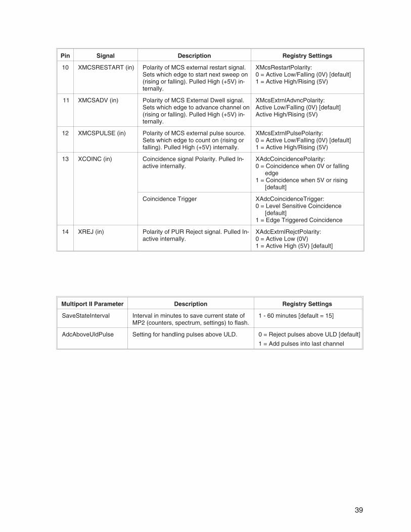
Pin Signal Description Registry Settings
10 XMCSRESTART (in) Polarity of MCS external restart signal.Sets which edge to start next sweep on(rising or falling). Pulled High (+5V) in-ternally.
XMcsRestartPolarity:0 = Active Low/Falling (0V) [default]1 = Active High/Rising (5V)
11 XMCSADV (in) Polarity of MCS External Dwell signal.Sets which edge to advance channel on(rising or falling). Pulled High (+5V) in-ternally.
XMcsExtrnlAdvncPolarity:Active Low/Falling (0V) [default]Active High/Rising (5V)
12 XMCSPULSE (in) Polarity of MCS external pulse source.Sets which edge to count on (rising orfalling). Pulled High (+5V) internally.
XMcsExtrnlPulsePolarity:0 = Active Low/Falling (0V) [default]1 = Active High/Rising (5V)
13 XCOINC (in) Coincidence signal Polarity. Pulled In-active internally.
XAdcCoincidencePolarity:0 = Coincidence when 0V or falling
edge1 = Coincidence when 5V or rising
[default]
Coincidence Trigger XAdcCoincidenceTrigger:0 = Level Sensitive Coincidence
[default]1 = Edge Triggered Coincidence
14 XREJ (in) Polarity of PUR Reject signal. Pulled In-active internally.
XAdcExtrnlRejctPolarity:0 = Active Low (0V)1 = Active High (5V) [default]
Multiport II Parameter Description Registry Settings
SaveStateInterval Interval in minutes to save current state ofMP2 (counters, spectrum, settings) to flash.
1 - 60 minutes [default = 15]
AdcAboveUldPulse Setting for handling pulses above ULD. 0 = Reject pulses above ULD [default]
1 = Add pulses into last channel
39

D. Software Installation
If your system wasn’t integrated by Canberra please follow the instructions on the Ge-nie-2000 installation CD to install the Genie-2000 software and purchased options.
Note: The Multiport II is supported under the following operating systems: Windows98, Windows Me, Windows NT® V4.0 (Ethernet only), Windows 2000, orWindows XP.
USB Driver InstallationThe USB driver must be installed for both Multiport II USB module and the MultiportII Ethernet/USB model, since the USB connection is required to configure theMultiport II’s Ethernet port. This cannot be performed on Windows NT systems due tolack of USB support. The Multiport II must be configured on a system that supportsUSB.
If this has not already been done please follow the directions below for setting up theUSB driver.
1. Connect the Multiport II to the host computer using the USB port and usingthe supplied USB cable. Please reference “Connecting the USB Cable” onpage 9.
2. Turn the Multiport II power to ON.
3. Windows 98/Me/2000/XP will automatically prompt you for the USB driverdiskette as part of its plug and play device architecture. There is no need tore-boot your system.
4. Follow the steps in the “Add New Hardware” Wizard to add your new USBdriver. Use the default steps by clicking “Next”.
5. Choose “Search for the best driver for your device” by clicking the Nextbutton (default).
6. Click on the check box for “specify a location”. The USB driver files,Mport2.inf and Mport2.sys, are located in the "CIUSB" folder on theinstallation CD or disk (disk #2).
Note: Window XP will display a warning message indicating the MultiportII driver is not signed. Acknowledge this menu and continue.
40
Software Installation

7. Click Next and Finish to complete the steps to install the USB driver. It isnot necessary to reboot.
Note: These steps are only required once, i.e. when Windows detects that new hard-ware has been added to your system or if the drivers are missing or need to bere-installed.
41
USB Driver Installation

E. Configuring the Ethernet Option
The Multiport II is configured at the factory for USB communications only. If youhave a Model MP2-nE with Ethernet/USB capability, you must configure its Ethernetoption before trying to communicate with your host computer via the Ethernet. TheUtility Multiport_II_Ethernet_Configuration.exe is installed into the“...Genie2k\Exefiles” directory. Run this utility to configure the Multiport II for Ether-net communication.
The Multiport_II_Ethernet_Configuration.exe utility mainly assigns an IP Addressor Network ID to the module, to allows it to communicate over Ethernet using TCP/IP.You can assign a Device Name (for systems using DHCP) or IP Address.
Note: USB communication with the Multiport II module is required to run the Ether-net Configuration Utility. Therefore, install the USB driver before running theconfiguration utility. Refer to Appendix D, Software Installation, for details.
The utility searches for any connected Multiport II modules (via USB) and lists themodules’ serial numbers (see Figure 23). It also determines whether or not eachmodule is a model Multiport II Ethernet, with Ethernet support. If not then the moduleis listed as “USB only”.
IP Address, Device name and Subnet Mask are validated according to standard rules,and appropriate error messages are displayed.
42
Configuring the Ethernet Option
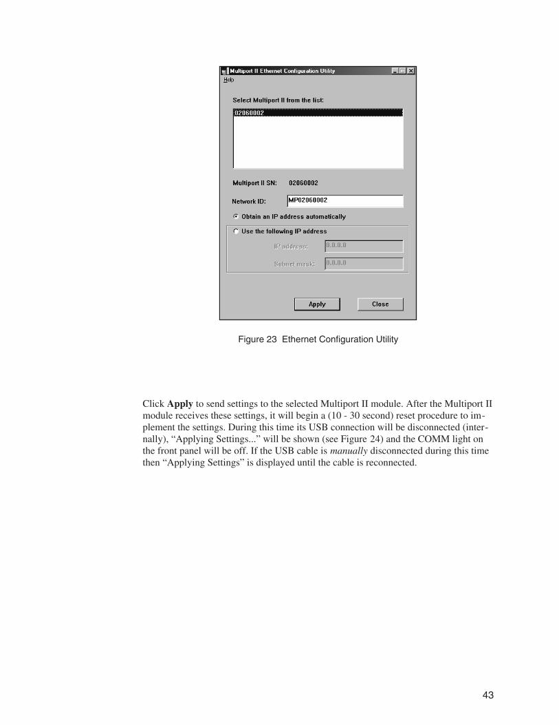
Click Apply to send settings to the selected Multiport II module. After the Multiport IImodule receives these settings, it will begin a (10 - 30 second) reset procedure to im-plement the settings. During this time its USB connection will be disconnected (inter-nally), “Applying Settings...” will be shown (see Figure 24) and the COMM light onthe front panel will be off. If the USB cable is manually disconnected during this timethen “Applying Settings” is displayed until the cable is reconnected.
43
Figure 23 Ethernet Configuration Utility
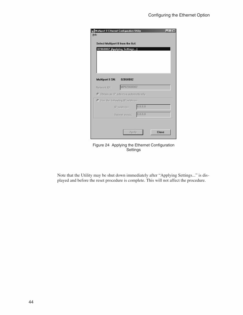
Note that the Utility may be shut down immediately after “Applying Settings...” is dis-played and before the reset procedure is complete. This will not affect the procedure.
44
Configuring the Ethernet Option
Figure 24 Applying the Ethernet ConfigurationSettings

F. Installation Considerations
This unit complies with all applicable European Union requirements.
Compliance testing was performed with application configurations commonly used forthis module; i.e. a CE compliant NIM Bin and Power Supply with additional CE com-pliant application-specific NIM were racked in a floor cabinet to support the moduleunder test.
During the design and assembly of the module, reasonable precautions were taken bythe manufacturer to minimize the effects of RFI and EMC on the system. However,care should be taken to maintain full compliance. These considerations include:
• A rack or tabletop enclosure fully closed on all sides with rear door access
• Single point external cable access
• Blank panels to cover open front panel Bin area
• Compliant grounding and safety precautions for any internal power distribution
• The use of CE compliant accessories such as fans, UPS, etc.
Any repairs or maintenance should be performed by a qualified Canberra servicerepresentative. Failure to use exact replacement components, or failure to reassemblethe unit as delivered, may affect the unit’s compliance with the specified EUrequirements.
45

G. Preventive Maintenance
Preventive maintenance is not required for this unit.
When needed, the front panel of the unit may be cleaned. Remove power from the unitbefore cleaning. Use only a soft cloth dampened with warm water and make sure theunit is fully dry before restoring power. Because of access holes in the NIM wrap, DONOT use any liquids to clean the wrap, side or rear panels.
46

Canberra (we, us, our) warrants to the customer (you, your) that for a period of ninety (90) days from the date ofshipment, software provided by us in connection with equipment manufactured by us shall operate in accordancewith applicable specifications when used with equipment manufactured by us and that the media on which thesoftware is provided shall be free from defects. We also warrant that (A) equipment manufactured by us shall befree from defects in materials and workmanship for a period of one (1) year from the date of shipment of suchequipment, and (B) services performed by us in connection with such equipment, such as site supervision andinstallation services relating to the equipment, shall be free from defects for a period of one (1) year from the date ofperformance of such services.
If defects in materials or workmanship are discovered within the applicable warranty period as set forth above, weshall, at our option and cost, (A) in the case of defective software or equipment, either repair or replace thesoftware or equipment, or (B) in the case of defective services, reperform such services.
LIMITATIONSEXCEPT AS SET FORTH HEREIN, NO OTHER WARRANTIES OR REMEDIES, WHETHER STATUTORY,WRITTEN, ORAL, EXPRESSED, IMPLIED (INCLUDING WITHOUT LIMITATION, THE WARRANTIES OFMERCHANTABILITY OR FITNESS FOR A PARTICULAR PURPOSE) OR OTHERWISE, SHALL APPLY. IN NOEVENT SHALL CANBERRA HAVE ANY LIABILITY FOR ANY SPECIAL, EXEMPLARY, PUNITIVE, INDIRECTOR CONSEQUENTIAL LOSSES OR DAMAGES OF ANY NATURE WHATSOEVER, WHETHER AS A RESULTOF BREACH OF CONTRACT, TORT LIABILITY (INCLUDING NEGLIGENCE), STRICT LIABILITY OROTHERWISE. REPAIR OR REPLACEMENT OF THE SOFTWARE OR EQUIPMENT DURING THEAPPLICABLE WARRANTY PERIOD AT CANBERRA'S COST, OR, IN THE CASE OF DEFECTIVE SERVICES,REPERFORMANCE AT CANBERRA'S COST, IS YOUR SOLE AND EXCLUSIVE REMEDY UNDER THISWARRANTY.
EXCLUSIONSOur warranty does not cover damage to equipment which has been altered or modified without our writtenpermission or damage which has been caused by abuse, misuse, accident, neglect or unusual physical orelectrical stress, as determined by our Service Personnel.
We are under no obligation to provide warranty service if adjustment or repair is required because of damagecaused by other than ordinary use or if the equipment is serviced or repaired, or if an attempt is made to service orrepair the equipment, by other than our Service Personnel without our prior approval.
Our warranty does not cover detector damage due to neutrons or heavy charged particles. Failure of beryllium,carbon composite, or polymer windows, or of windowless detectors caused by physical or chemical damage fromthe environment is not covered by warranty.
We are not responsible for damage sustained in transit. You should examine shipments upon receipt for evidenceof damage caused in transit. If damage is found, notify us and the carrier immediately. Keep all packages,materials and documents, including the freight bill, invoice and packing list.
When purchasing our software, you have purchased a license to use the software, not the software itself. Becausetitle to the software remains with us, you may not sell, distribute or otherwise transfer the software. This licenseallows you to use the software on only one computer at a time. You must get our written permission for anyexception to this limited license.
BACKUP COPIESOur software is protected by United States Copyright Law and by International Copyright Treaties. You have ourexpress permission to make one archival copy of the software for backup protection. You may not copy oursoftware or any part of it for any other purpose.
Revised 1 Apr 03


![TOWARDS VATICAN II’S CENTENARY: YOUR NEXT FIFTY YEARS · 2017-07-08 · TOWARDS VATICAN II’S CENTENARY: YOUR NEXT FIFTY YEARS ... Fall 2016] TOWARDS VATICAN II’S CENTENARY 5](https://img.pdfslide.net/doc/110x75/5e7bcc2c5f9e2b0e0173ef43/towards-vatican-iias-centenary-your-next-fifty-years-2017-07-08-towards-vatican.jpg)