Embed Size (px)
Citation preview

Product Data Sheet 00813-0100-4799
Model 3244MVMultiVariable Temperature Transmitterwith Profibus PAPROFIBUS PA CAPABILITIES
• Can be integrated to a Profibus DP network
• Reduces wiring costs and installationcommissioning, operation, and maintenancetime compared to traditional smart transmitters
MULTIVARIABLE BENEFITS
• Reduce process variability with differentialtemperature measurement
• Pre-configure your transmitter at theRosemount® factory with customconfiguration options
SUPERIOR PERFORMANCEAND RELIABILITY
• Accuracy: ±0.10 °C (± 0.18 °F) for Pt 100 RTDs
• 5 year stability
• 18 bit analog-to-digital converter with ambienttemperature compensation providesoutstanding measurement performance
• Dual-compartment housing provides superiorreliability in high-humidity, corrosive, and RFIenvironments
COMPLETE POINT SOLUTIONS ™
Have your temperature assembly shippedinstallation-ready.
This complete temperature assembly includes thetransmitter, sensor, extension, and thermowell.This assembly is shipped fully assembled,calibrated, wired and configured.
VISIT ROSEMOUNT PRODUCTS ON THE
WORLD WIDE WEB AT
WWW.ROSEMOUNT.COM
Model 3244MV MultiVariable Temperature Transmitter with Profibus PA
2
TRANSMITTER DESCRIPTION
Inputs
The transmitter is compatible with any of the temperature sensor listed below:
2-, 3-, and 4-wire RTD Sensors
• Pt 100
• Pt 200
• Pt 500
• Pt 1000 (a = 0.00385)
• Pt 100 (a = 0.003916)
• Ni 120
• Cu 10
Thermocouples (1)
• Type B
• Type E
• Type J
• Type K
• Type N
• Type R
• Type S
• Type T
Millivolt Input Sensors
• –10 to 100 millivolts
2-, 3-, and 4-wire Ohm Input Sensors
• 0 to 2000 ohms
Custom Input Sensors
• Special RTD or thermocouple calibration schedules
• NIST Type C thermocouple
Refer to Table 1 on page 7 for a complete listing of input options and specifications.
The sensor type and configuration are software-selectable using any Profibus PA Class 2-compliant host. In addition, you can select appropriate display scaling for convenient readout directly in engineering units including Celsius, Fahrenheit, Kelvin, Rankine scale, millivolts, and ohms.
A complete line of temperature sensors, thermowells, and accessory mounting hardware are available from Rosemount Inc. Refer to the Temperature Sensors and Accessories for Temperature Transmitter Assemblies Product Data Sheets, Volumes 1, 2, or 3.
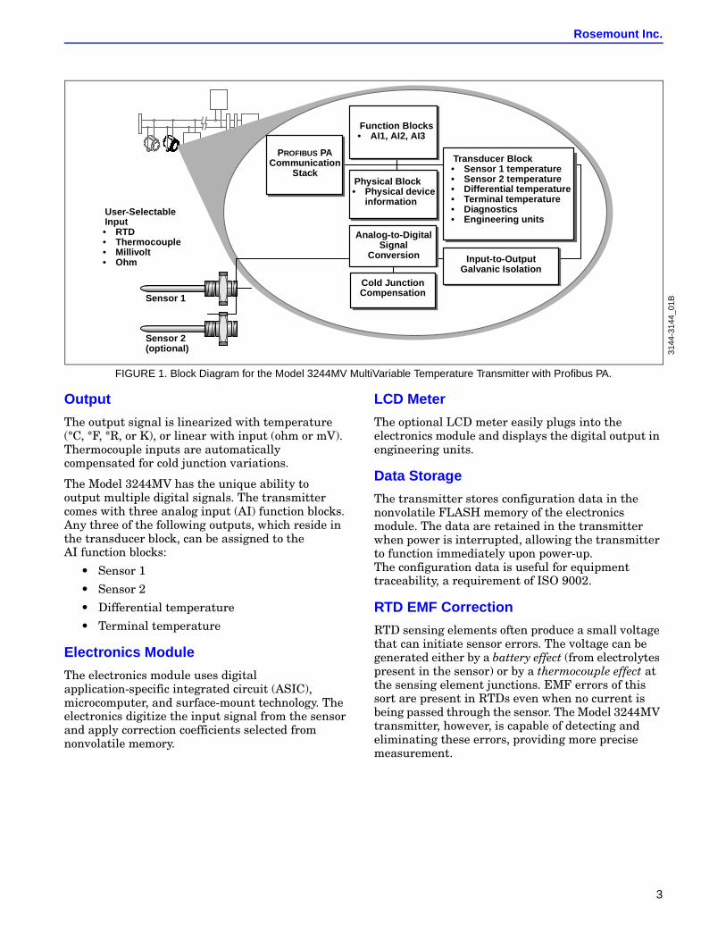
Figure 1 illustrates how a temperature signal is channelled through the transmitter.
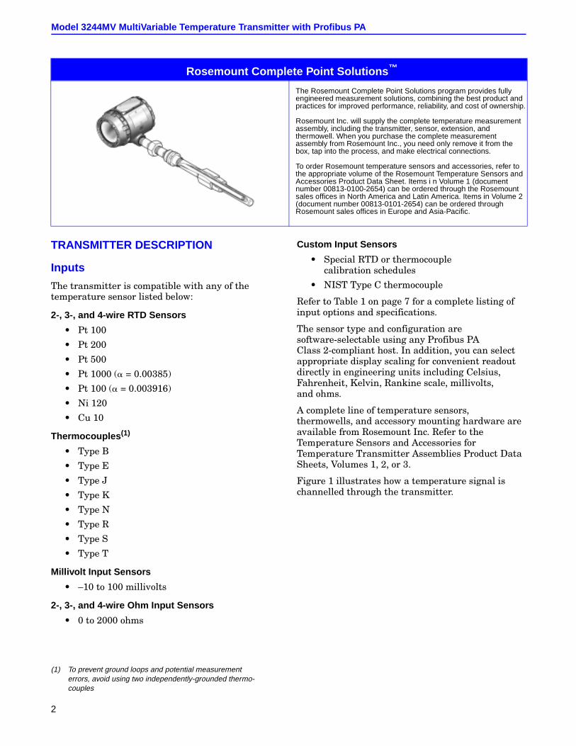
Rosemount Complete Point Solutions ™
The Rosemount Complete Point Solutions program provides fullyengineered measurement solutions, combining the best product andpractices for improved performance, reliability, and cost of ownership.
Rosemount Inc. will supply the complete temperature measurementassembly, including the transmitter, sensor, extension, andthermowell. When you purchase the complete measurementassembly from Rosemount Inc., you need only remove it from thebox, tap into the process, and make electrical connections.
To order Rosemount temperature sensors and accessories, refer tothe appropriate volume of the Rosemount Temperature Sensors andAccessories Product Data Sheet. Items i n Volume 1 (documentnumber 00813-0100-2654) can be ordered through the Rosemountsales offices in North America and Latin America. Items in Volume 2(document number 00813-0101-2654) can be ordered throughRosemount sales offices in Europe and Asia-Pacific.
(1) To prevent ground loops and potential measurementerrors, avoid using two independently-grounded thermo-couples
Rosemount Inc.
3
FIGURE 1. Block Diagram for the Model 3244MV MultiVariable Temperature Transmitter with Profibus PA.
Output
The output signal is linearized with temperature (°C, °F, °R, or K), or linear with input (ohm or mV). Thermocouple inputs are automatically compensated for cold junction variations.
The Model 3244MV has the unique ability to output multiple digital signals. The transmitter comes with three analog input (AI) function blocks. Any three of the following outputs, which reside in the transducer block, can be assigned to the AI function blocks:
• Sensor 1
• Sensor 2
• Differential temperature
• Terminal temperature
Electronics Module
The electronics module uses digital application-specific integrated circuit (ASIC), microcomputer, and surface-mount technology. The electronics digitize the input signal from the sensor and apply correction coefficients selected from nonvolatile memory.
LCD Meter
The optional LCD meter easily plugs into the electronics module and displays the digital output in engineering units.
Data Storage
The transmitter stores configuration data in the nonvolatile FLASH memory of the electronics module. The data are retained in the transmitter when power is interrupted, allowing the transmitter to function immediately upon power-up.The configuration data is useful for equipment traceability, a requirement of ISO 9002.
RTD EMF Correction
RTD sensing elements often produce a small voltage that can initiate sensor errors. The voltage can be generated either by a battery effect (from electrolytes present in the sensor) or by a thermocouple effect at the sensing element junctions. EMF errors of this sort are present in RTDs even when no current is being passed through the sensor. The Model 3244MV transmitter, however, is capable of detecting and eliminating these errors, providing more precise measurement.
Analog-to-DigitalSignal
Conversion
Cold JunctionCompensation
Input-to-OutputGalvanic Isolation
Transducer Block• Sensor 1 temperature• Sensor 2 temperature• Differential temperature• Terminal temperature• Diagnostics• Engineering units
Function Blocks• AI1, AI2, AI3
Physical Block• Physical device
information
PROFIBUS PACommunication
Stack
User-SelectableInput• RTD• Thermocouple• Millivolt• Ohm
Sensor 1
Sensor 2(optional) 31
44-3
144_
01B
Model 3244MV MultiVariable Temperature Transmitter with Profibus PA
4
SOFTWARE CAPABILITIES
The software used in the transmitter allows for remote testing and configuration using any Profibus PA Class 2-compliant host.
Transducer Blocks
Transducer blocks (TB) allow several inputs to be read by the host. TB1 contains sensor 1 data, TB2 contains sensor 2 data, and TB3 contains sensor differential data. All TBs contain the terminal temperature. Multiple transducer blocks give any Profibus PA Class 2-compliant host the ability to configure basic device features.
The Siemens Profibus PA Class 2-compliant host, through the use of device description files, allows for additional configuration parameters, including:
• Special sensor types
• Calibration
• Diagnostics
• LCD meter configuration.
Physical Block
The physical block contains transmitter information including:
• Available memory
• Manufacturer identification
• Device type
• Software tag
• Any additional identification.
Analog Input Function Block
The analog input function block processes the measurement and makes it available to other function blocks. Using this block, the following can be changed:
• Filtering
• Alarming
• Engineering unit
Basic Configuration
Basic configuration of the of the Model 3244MV requires connecting the transmitter to a power supply, connecting the sensor, and defining operational parameters.
The transmitter is easily configurable using any Profibus PA Class 2 compliant host. The following are some examples of user-configurable parameters:
• Sensor type
• Number of sensor input wires
• Damping
• Engineering unit selection
Tagging information can be entered into the transmitter to allow identification and a physical description. 30-character tags are provided for identification of the transmitter and each function block.
Advanced Configuration
Using the Siemens Profibus PA Class 2-compliant host, the transmitter can be configured for advanced features such as:
• Transmitter-Sensor Matching
• LCD meter configuration
• 50 or 60 Hz line filtering option
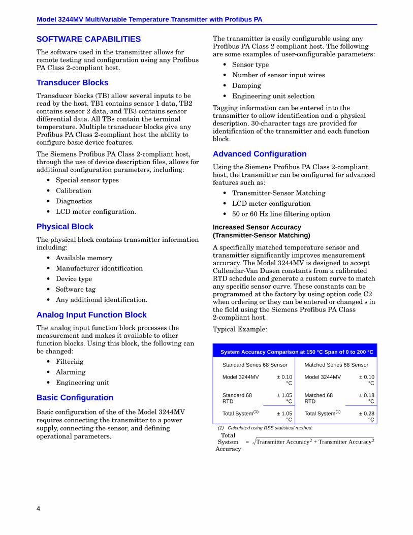
Increased Sensor Accuracy(Transmitter-Sensor Matching)
A specifically matched temperature sensor and transmitter significantly improves measurement accuracy. The Model 3244MV is designed to accept Callendar-Van Dusen constants from a calibrated RTD schedule and generate a custom curve to match any specific sensor curve. These constants can be programmed at the factory by using option code C2 when ordering or they can be entered or changed s in the field using the Siemens Profibus PA Class 2-compliant host.
Typical Example:
System Accuracy Comparison at 150 °C Span of 0 to 200 °C
Standard Series 68 Sensor Matched Series 68 Sensor
Model 3244MV ± 0.10°C
Model 3244MV ± 0.10°C
Standard 68RTD
± 1.05°C
Matched 68RTD
± 0.18°C
Total System(1)
(1) Calculated using RSS statistical method:
± 1.05°C
Total System(1) ± 0.28°C
Transmitter Accuracy2 Transmitter Accuracy2+=Total
System Accuracy
Rosemount Inc.
5
Specifications and Reference Data
FUNCTIONAL SPECIFICATIONS
InputsSee Table 1. User-selectable. (sensor terminals are rated to 42.4 V dc.)
OutputsManchester-encoded digital signal that conforms to IEC 1158-2 and ISA 50.02.
IsolationInput/output isolation tested to 500 V rms (707 V dc).
Power SupplyExternal power supply required. Transmitter operates between 9.0 and 32.0 V dc, 17.5 mA maximum. (Transmitter power terminals are rated to 42.4 V dc.)
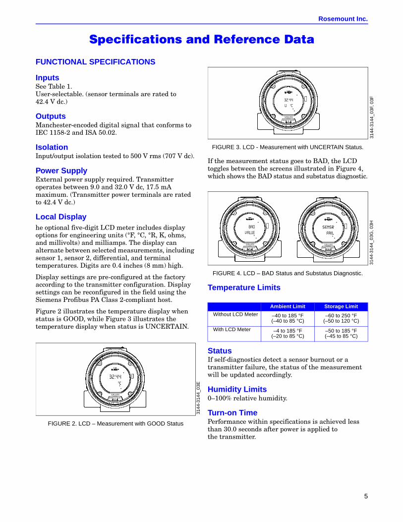
Local Displayhe optional five-digit LCD meter includes display options for engineering units (°F, °C, °R, K, ohms, and millivolts) and milliamps. The display can alternate between selected measurements, including sensor 1, sensor 2, differential, and terminal temperatures. Digits are 0.4 inches (8 mm) high.
Display settings are pre-configured at the factory according to the transmitter configuration. Display settings can be reconfigured in the field using the Siemens Profibus PA Class 2-compliant host.
Figure 2 illustrates the temperature display when status is GOOD, while Figure 3 illustrates the temperature display when status is UNCERTAIN.
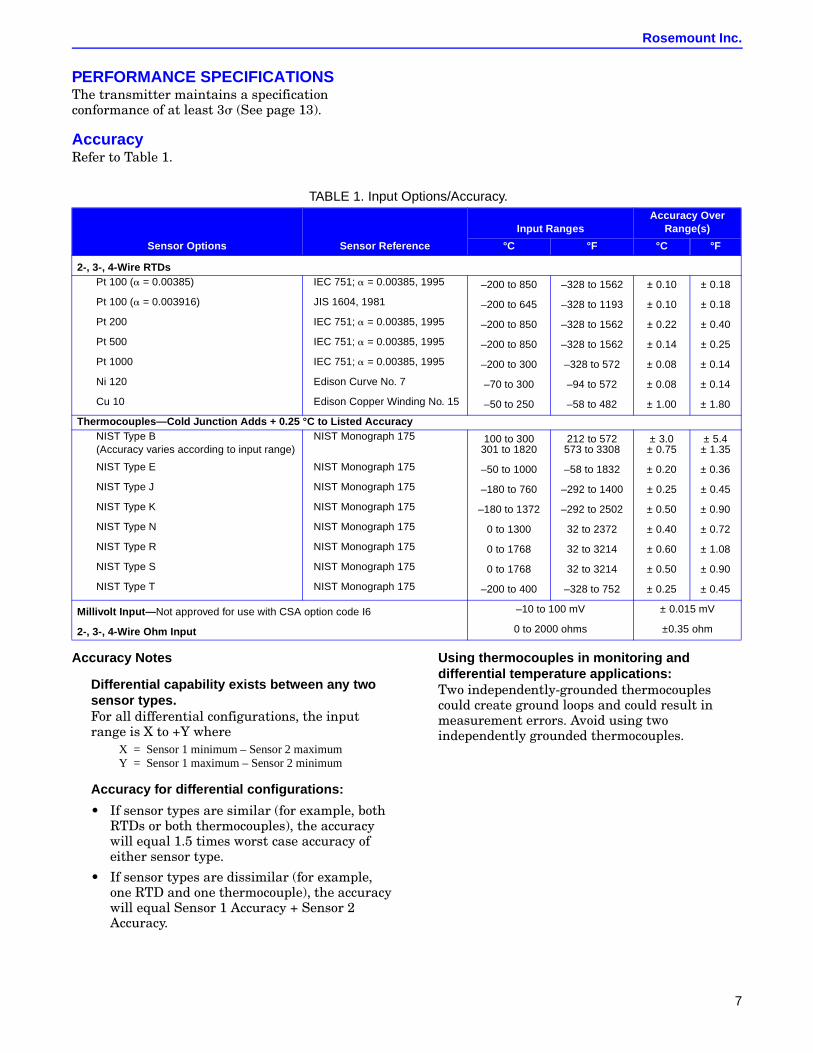
FIGURE 2. LCD – Measurement with GOOD Status
FIGURE 3. LCD - Measurement with UNCERTAIN Status.
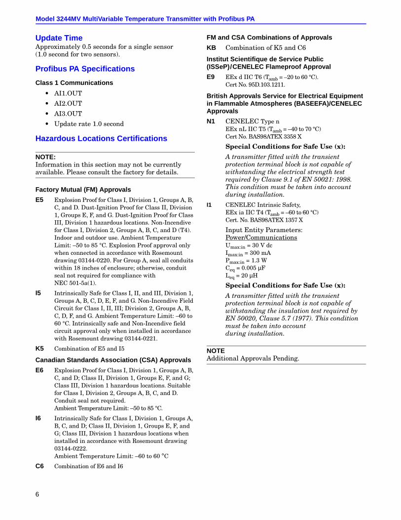
If the measurement status goes to BAD, the LCD toggles between the screens illustrated in Figure 4, which shows the BAD status and substatus diagnostic.
FIGURE 4. LCD – BAD Status and Substatus Diagnostic.
Temperature Limits
StatusIf self-diagnostics detect a sensor burnout or a transmitter failure, the status of the measurement will be updated accordingly.
Humidity Limits0–100% relative humidity.
Turn-on TimePerformance within specifications is achieved less than 30.0 seconds after power is applied to the transmitter.
3144
-314
4_03
E
Ambient Limit Storage Limit
Without LCD Meter –40 to 185 °F(–40 to 85 °C)
–60 to 250 °F(–50 to 120 °C)
With LCD Meter –4 to 185 °F(–20 to 85 °C)
–50 to 185 °F(–45 to 85 °C)
3144
-314
4_03
F,03
F31
44-3
144_
03G
,03H
Model 3244MV MultiVariable Temperature Transmitter with Profibus PA
6
Update TimeApproximately 0.5 seconds for a single sensor (1.0 second for two sensors).
Profibus PA Specifications
Class 1 Communications
• AI1.OUT
• AI2.OUT
• AI3.OUT
• Update rate 1.0 second
Hazardous Locations Certifications
NOTE:Information in this section may not be currently available. Please consult the factory for details.
Factory Mutual (FM) Approvals
E5 Explosion Proof for Class I, Division 1, Groups A, B, C, and D. Dust-Ignition Proof for Class II, Division 1, Groups E, F, and G. Dust-Ignition Proof for Class III, Division 1 hazardous locations. Non-Incendive for Class I, Division 2, Groups A, B, C, and D (T4). Indoor and outdoor use. Ambient Temperature Limit: –50 to 85 °C. Explosion Proof approval only when connected in accordance with Rosemount drawing 03144-0220. For Group A, seal all conduits within 18 inches of enclosure; otherwise, conduit seal not required for compliance with NEC 501-5a(1).
I5 Intrinsically Safe for Class I, II, and III, Division 1, Groups A, B, C, D, E, F, and G. Non-Incendive Field Circuit for Class I, II, III; Division 2, Groups A, B, C, D, F, and G. Ambient Temperature Limit: –60 to 60 °C. Intrinsically safe and Non-Incendive field circuit approval only when installed in accordance with Rosemount drawing 03144-0221.
K5 Combination of E5 and I5
Canadian Standards Association (CSA) Approvals
E6 Explosion Proof for Class I, Division 1, Groups A, B, C, and D; Class II, Division 1, Groups E, F, and G; Class III, Division 1 hazardous locations. Suitable for Class I, Division 2, Groups A, B, C, and D. Conduit seal not required. Ambient Temperature Limit: –50 to 85 °C.
I6 Intrinsically Safe for Class I, Division 1, Groups A, B, C, and D; Class II, Division 1, Groups E, F, and G; Class III, Division 1 hazardous locations when installed in accordance with Rosemount drawing 03144-0222. Ambient Temperature Limit: –60 to 60 °C
C6 Combination of E6 and I6
FM and CSA Combinations of Approvals
KB Combination of K5 and C6
Institut Scientifique de Service Public(ISSeP)/CENELEC Flameproof Approval
E9 EEx d IIC T6 (Tamb = –20 to 60 °C).Cert No. 95D.103.1211.
British Approvals Service for Electrical Equipmentin Flammable Atmospheres (BASEEFA)/CENELECApprovals
N1 CENELEC Type n EEx nL IIC T5 (Tamb = –40 to 70 °C)Cert No. BAS98ATEX 3358 X
Special Conditions for Safe Use (x):
A transmitter fitted with the transient protection terminal block is not capable of withstanding the electrical strength test required by Clause 9.1 of EN 50021: 1998. This condition must be taken into account during installation.
I1 CENELEC Intrinsic Safety, EEx ia IIC T4 (Tamb = –60 to 60 °C)Cert. No. BAS98ATEX 1357 X
Input Entity Parameters:Power/CommunicationsUmax:in = 30 V dcImax:in = 300 mAPmax:in = 1.3 WCeq = 0.005 µFLeq = 20 µH
Special Conditions for Safe Use (x):
A transmitter fitted with the transient protection terminal block is not capable of withstanding the insulation test required by EN 50020, Clause 5.7 (1977). This condition must be taken into account during installation.
NOTEAdditional Approvals Pending.
Rosemount Inc.
7
PERFORMANCE SPECIFICATIONSThe transmitter maintains a specification conformance of at least 3s (See page 13).
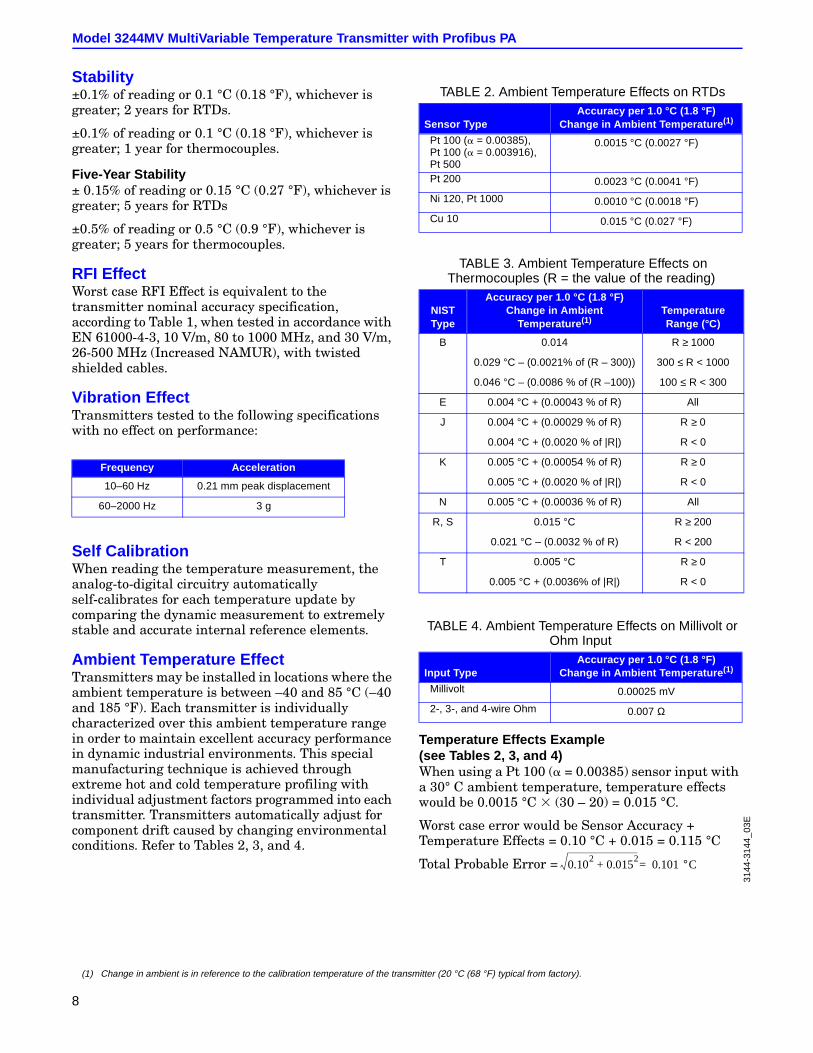
AccuracyRefer to Table 1.
Accuracy Notes
Differential capability exists between any twosensor types.For all differential configurations, the input range is X to +Y where
Accuracy for differential configurations:
• If sensor types are similar (for example, both RTDs or both thermocouples), the accuracy will equal 1.5 times worst case accuracy of either sensor type.
• If sensor types are dissimilar (for example, one RTD and one thermocouple), the accuracy will equal Sensor 1 Accuracy + Sensor 2 Accuracy.
Using thermocouples in monitoring anddifferential temperature applications:Two independently-grounded thermocouples could create ground loops and could result in measurement errors. Avoid using two independently grounded thermocouples.
TABLE 1. Input Options/Accuracy.
Sensor Options Sensor Reference
Input RangesAccuracy Over
Range(s)
°C °F °C °F
2-, 3-, 4-Wire RTDsPt 100 (a = 0.00385) IEC 751; a = 0.00385, 1995 –200 to 850 –328 to 1562 ± 0.10 ± 0.18
Pt 100 (a = 0.003916) JIS 1604, 1981 –200 to 645 –328 to 1193 ± 0.10 ± 0.18
Pt 200 IEC 751; a = 0.00385, 1995 –200 to 850 –328 to 1562 ± 0.22 ± 0.40
Pt 500 IEC 751; a = 0.00385, 1995 –200 to 850 –328 to 1562 ± 0.14 ± 0.25
Pt 1000 IEC 751; a = 0.00385, 1995 –200 to 300 –328 to 572 ± 0.08 ± 0.14
Ni 120 Edison Curve No. 7 –70 to 300 –94 to 572 ± 0.08 ± 0.14
Cu 10 Edison Copper Winding No. 15 –50 to 250 –58 to 482 ± 1.00 ± 1.80
Thermocouples—Cold Junction Adds + 0.25 °C to Listed AccuracyNIST Type B(Accuracy varies according to input range)
NIST Monograph 175 100 to 300301 to 1820
212 to 572573 to 3308
± 3.0± 0.75
± 5.4± 1.35
NIST Type E NIST Monograph 175 –50 to 1000 –58 to 1832 ± 0.20 ± 0.36
NIST Type J NIST Monograph 175 –180 to 760 –292 to 1400 ± 0.25 ± 0.45
NIST Type K NIST Monograph 175 –180 to 1372 –292 to 2502 ± 0.50 ± 0.90
NIST Type N NIST Monograph 175 0 to 1300 32 to 2372 ± 0.40 ± 0.72
NIST Type R NIST Monograph 175 0 to 1768 32 to 3214 ± 0.60 ± 1.08
NIST Type S NIST Monograph 175 0 to 1768 32 to 3214 ± 0.50 ± 0.90
NIST Type T NIST Monograph 175 –200 to 400 –328 to 752 ± 0.25 ± 0.45
Millivolt Input— Not approved for use with CSA option code I6 –10 to 100 mV ± 0.015 mV
2-, 3-, 4-Wire Ohm Input 0 to 2000 ohms ±0.35 ohm
X Sensor 1 minimum Sensor 2 maximum–=Y Sensor 1 maximum Sensor 2 minimum–=
Model 3244MV MultiVariable Temperature Transmitter with Profibus PA
8
Stability±0.1% of reading or 0.1 °C (0.18 °F), whichever is greater; 2 years for RTDs.
±0.1% of reading or 0.1 °C (0.18 °F), whichever is greater; 1 year for thermocouples.
Five-Year Stability± 0.15% of reading or 0.15 °C (0.27 °F), whichever is greater; 5 years for RTDs
±0.5% of reading or 0.5 °C (0.9 °F), whichever is greater; 5 years for thermocouples.
RFI EffectWorst case RFI Effect is equivalent to the transmitter nominal accuracy specification, according to Table 1, when tested in accordance with EN 61000-4-3, 10 V/m, 80 to 1000 MHz, and 30 V/m, 26-500 MHz (Increased NAMUR), with twisted shielded cables.
Vibration EffectTransmitters tested to the following specifications with no effect on performance:
Self CalibrationWhen reading the temperature measurement, the analog-to-digital circuitry automatically self-calibrates for each temperature update by comparing the dynamic measurement to extremely stable and accurate internal reference elements.
Ambient Temperature EffectTransmitters may be installed in locations where the ambient temperature is between –40 and 85 °C (–40 and 185 °F). Each transmitter is individually characterized over this ambient temperature range in order to maintain excellent accuracy performance in dynamic industrial environments. This special manufacturing technique is achieved through extreme hot and cold temperature profiling with individual adjustment factors programmed into each transmitter. Transmitters automatically adjust for component drift caused by changing environmental conditions. Refer to Tables 2, 3, and 4.
(1)
Temperature Effects Example(see Tables 2, 3, and 4)When using a Pt 100 (a = 0.00385) sensor input with a 30° C ambient temperature, temperature effects would be 0.0015 °C 3 (30 – 20) = 0.015 °C.
Worst case error would be Sensor Accuracy + Temperature Effects = 0.10 °C + 0.015 = 0.115 °C
Total Probable Error =
Frequency Acceleration
10–60 Hz 0.21 mm peak displacement
60–2000 Hz 3 g
TABLE 2. Ambient Temperature Effects on RTDs
Sensor TypeAccuracy per 1.0 °C (1.8 °F)
Change in Ambient Temperature (1)
Pt 100 (a = 0.00385),Pt 100 (a = 0.003916),Pt 500
0.0015 °C (0.0027 °F)
Pt 200 0.0023 °C (0.0041 °F)
Ni 120, Pt 1000 0.0010 °C (0.0018 °F)
Cu 10 0.015 °C (0.027 °F)
TABLE 3. Ambient Temperature Effects onThermocouples (R = the value of the reading)
NISTType
Accuracy per 1.0 °C (1.8 °F)Change in Ambient
Temperature (1)TemperatureRange (°C)
B 0.014 R ≥ 1000
0.029 °C – (0.0021% of (R – 300)) 300 ≤ R < 1000
0.046 °C – (0.0086 % of (R –100)) 100 ≤ R < 300
E 0.004 °C + (0.00043 % of R) All
J 0.004 °C + (0.00029 % of R) R ≥ 0
0.004 °C + (0.0020 % of |R|) R < 0
K 0.005 °C + (0.00054 % of R) R ≥ 0
0.005 °C + (0.0020 % of |R|) R < 0
N 0.005 °C + (0.00036 % of R) All
R, S 0.015 °C R ≥ 200
0.021 °C – (0.0032 % of R) R < 200
T 0.005 °C R ≥ 0
0.005 °C + (0.0036% of |R|) R < 0
TABLE 4. Ambient Temperature Effects on Millivolt orOhm Input
Input TypeAccuracy per 1.0 °C (1.8 °F)
Change in Ambient Temperature (1)
Millivolt 0.00025 mV
2-, 3-, and 4-wire Ohm 0.007 Ω
(1) Change in ambient is in reference to the calibration temperature of the transmitter (20 °C (68 °F) typical from factory).
0.102
0.0152
+ 0.101°C=
3144
-314
4_03
E
Rosemount Inc.
9
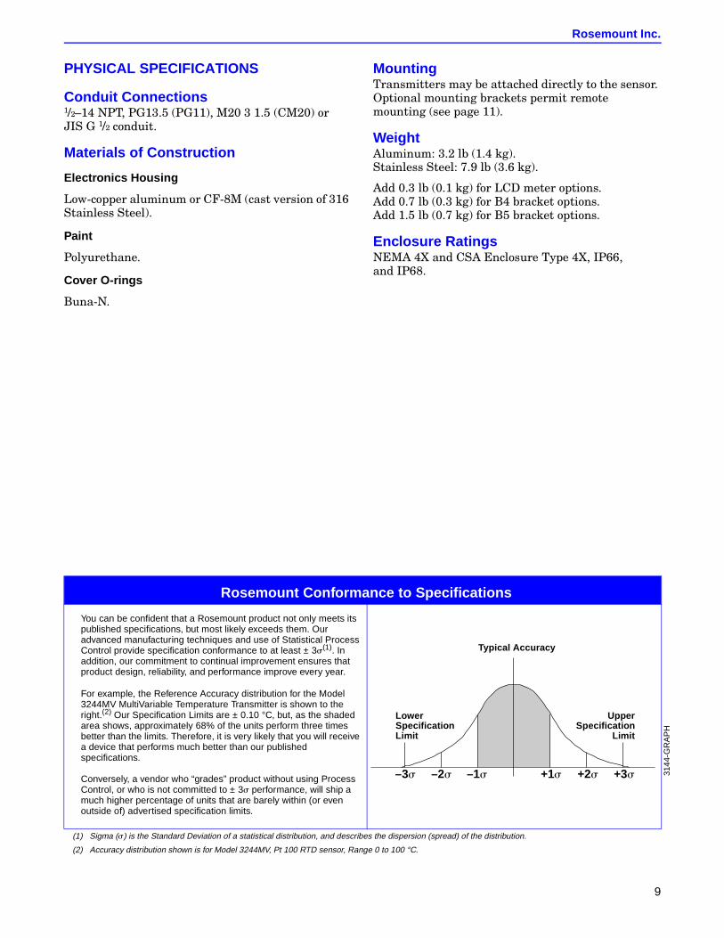
PHYSICAL SPECIFICATIONS
Conduit Connections1/2–14 NPT, PG13.5 (PG11), M20 3 1.5 (CM20) or JIS G 1/2 conduit.
Materials of Construction
Electronics Housing
Low-copper aluminum or CF-8M (cast version of 316 Stainless Steel).
Paint
Polyurethane.
Cover O-rings
Buna-N.
MountingTransmitters may be attached directly to the sensor. Optional mounting brackets permit remote mounting (see page 11).
WeightAluminum: 3.2 lb (1.4 kg).Stainless Steel: 7.9 lb (3.6 kg).
Add 0.3 lb (0.1 kg) for LCD meter options.Add 0.7 lb (0.3 kg) for B4 bracket options.Add 1.5 lb (0.7 kg) for B5 bracket options.
Enclosure RatingsNEMA 4X and CSA Enclosure Type 4X, IP66, and IP68.
Rosemount Conformance to Specifications
You can be confident that a Rosemount product not only meets itspublished specifications, but most likely exceeds them. Ouradvanced manufacturing techniques and use of Statistical ProcessControl provide specification conformance to at least ± 3s(1). Inaddition, our commitment to continual improvement ensures thatproduct design, reliability, and performance improve every year.
For example, the Reference Accuracy distribution for the Model3244MV MultiVariable Temperature Transmitter is shown to theright.(2) Our Specification Limits are ± 0.10 °C, but, as the shadedarea shows, approximately 68% of the units perform three timesbetter than the limits. Therefore, it is very likely that you will receivea device that performs much better than our publishedspecifications.
Conversely, a vendor who “grades” product without using ProcessControl, or who is not committed to ± 3s performance, will ship amuch higher percentage of units that are barely within (or evenoutside of) advertised specification limits.
(1) Sigma (s) is the Standard Deviation of a statistical distribution, and describes the dispersion (spread) of the distribution.
(2) Accuracy distribution shown is for Model 3244MV, Pt 100 RTD sensor, Range 0 to 100 °C.
–3s +3s–2s –1s +2s+1s
LowerSpecificationLimit
UpperSpecification
Limit
Typical Accuracy
3144
-GR
AP
H
Model 3244MV MultiVariable Temperature Transmitter with Profibus PA
10
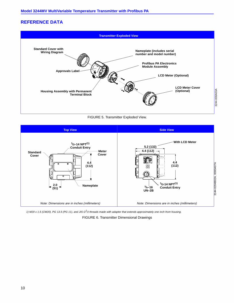
REFERENCE DATA
FIGURE 5. Transmitter Exploded View.
FIGURE 6. Transmitter Dimensional Drawings
Transmitter Exploded View
Standard Cover withWiring Diagram
Housing Assembly with PermanentTerminal Block
Nameplate (includes serialnumber and model number)
Profibus PA ElectronicsModule Assembly
Approvals LabelLCD Meter (Optional)
LCD Meter Cover(Optional)
3244
-000
A03
A
Top View Side View
Note: Dimensions are in inches (millimeters) Note: Dimensions are in inches (millimeters)
1) M20 x 1.5 (CM20), PG 13.5 (PG 11), and JIS G1/2 threads made with adapter that extends approximately one inch from housing.
StandardCover
1/2–14 NPT(1)
Conduit EntryMeterCover
Nameplate2.0(51)
4.4(112)
5.2 (132)4.4 (112)
3/8–16UN–2B
With LCD Meter
3144
-020
4B02
A,0
000A
07A4.4
(112)
1/2-14 NPT(1)
Conduit Entry
Rosemount Inc.
11
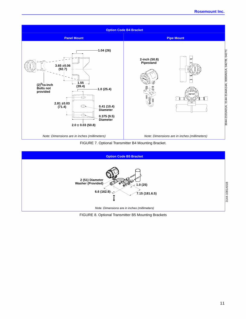
FIGURE 7. Optional Transmitter B4 Mounting Bracket.
FIGURE 8. Optional Transmitter B5 Mounting Brackets
Option Code B4 Bracket
Panel Mount Pipe Mount
Note: Dimensions are in inches (millimeters) Note: Dimensions are in inches (millimeters)
3.65 ±0.06(92.7)
1.55(39.4)
2.81 ±0.03(71.4)
(2)5/16-inchBolts notprovided
2.0 ± 0.03 (50.8)
0.41 (10.4)Diameter
1.04 (26)
1.0 (25.4)
0.375 (9.5)Diameter
2-inch (50.8)Pipestand
3044
-210
1A01
A,3
144-
3144
A14
A,0
000A
01A
,042
7B,0
427C
Option Code B5 Bracket
ÿþýüûúùø÷üöõøþöõúôóüúøöúøöòñüõúð÷øïïø÷üýüóõî
1.0 (25)
2 (51) DiameterWasher (Provided)
6.6 (162.6) 7.15 (181.6.5)
3144
-108
1A01
B
Model 3244MV MultiVariable Temperature Transmitter with Profibus PA
12
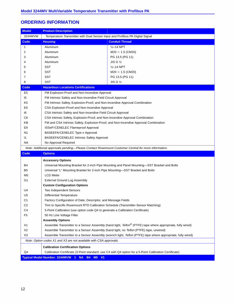
ORDERING INFORMATION
Model Product Description
3244MVW Temperature Transmitter with Dual Sensor Input and Profibus PA Digital Signal
Code Housing Conduit Thread
1 Aluminum ½–14 NPT
2 Aluminum M20 3 1.5 (CM20)
3 Aluminum PG 13.5 (PG 11)
4 Aluminum JIS G ½
5 SST ½–14 NPT
6 SST M20 3 1.5 (CM20)
7 SST PG 13.5 (PG 11)
8 SST JIS G ½
Code Hazardous Locations Certifications
E5 FM Explosion-Proof and Non-Incendive Approval
I5 FM Intrinsic Safety and Non-Incendive Field Circuit Approval
K5 FM Intrinsic Safety, Explosion-Proof, and Non-Incendive Approval Combination
E6 CSA Explosion-Proof and Non-Incendive Approval
I6 CSA Intrinsic Safety and Non-Incendive Field Circuit Approval
C6 CSA Intrinsic Safety, Explosion-Proof, and Non-Incendive Approval Combination
KB FM and CSA Intrinsic Safety, Explosion-Proof, and Non-Incendive Approval Combination
E9 ISSeP/CENELEC Flameproof Approval
N1 BASEEFA/CENELEC Type n Approval
I1 BASEEFA/CENELEC Intrinsic Safety Approval
NA No Approval Required
Note: Additional approvals pending—Please Contact Rosemount Customer Central for more information.
Code Options
Accessory Options
B4 Universal Mounting Bracket for 2-inch Pipe Mounting and Panel Mounting—SST Bracket and Bolts
B5 Universal “L” Mounting Bracket for 2-inch Pipe Mounting—SST Bracket and Bolts
M5 LCD Meter
G1 External Ground Lug Assembly
Custom Configuration Options
U4 Two Independent Sensors
U5 Differential Temperature
C1 Factory Configuration of Date, Descriptor, and Message Fields
C2 Trim to Specific Rosemount RTD Calibration Schedule (Transmitter-Sensor Matching)
C4 5-Point Calibration (use option code Q4 to generate a Calibration Certificate)
F5 50 Hz Line Voltage Filter
Assembly Options
X1 Assemble Transmitter to a Sensor Assembly (hand tight, Teflon® (PTFE) tape where appropriate, fully wired)
X2 Assemble Transmitter to a Sensor Assembly (hand tight, no Teflon (PTFE) tape, unwired)
X3 Assemble Transmitter to a Sensor Assembly (wrench tight, Teflon (PTFE) tape where appropriate, fully wired)
Note: Option codes X1 and X3 are not available with CSA approvals.
Calibration Certification Options
Q4 Calibration Certificate (3-Point standard; use C4 with Q4 option for a 5-Point Calibration Certificate)
Typical Model Number: 3244MVW 1 NA B4 M5 X1
Rosemount Inc.
13
Tagging
Hardware Tag
• no charge
• tagged in accordance with customer requirements
• stainless steel construction
• permanently attached to transmitter
• character height is 1/16-in. (1.6 mm)
Software Tag
• no charge
• transmitter can store up to 30 characters. If no such characters are specified, the first 30 characters of the hardware tag are used as the default.
TRANSMITTER CONFIGURATIONThe transmitter is available from the factory with either the standard configuration or one of the custom configuration options when specified in the model number. Use “Configuration Data Sheet” on page 15 if any modifications are needed to the selected configuration.
The configuration settings and block configuration may be changed in the field using a Profibus PA Class 2-compliant host.
Custom ConfigurationIf you want to have the Model 3244MV factory configured for one of the applications described under ”Monitoring Applications — Option Code U4 (Two Independent Sensors)‚’ indicate the appropriate option code in the model number when ordering. If you do not order one of these option codes, the transmitter will be shipped with its standard configuration.
Standard Configuration
Unless otherwise specified, the transmitter will be shipped as follows:
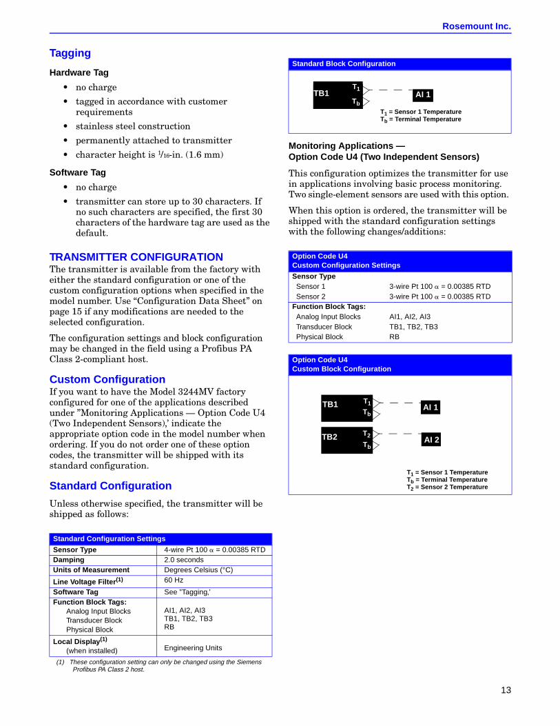
Monitoring Applications —Option Code U4 (Two Independent Sensors)
This configuration optimizes the transmitter for use in applications involving basic process monitoring. Two single-element sensors are used with this option.
When this option is ordered, the transmitter will be shipped with the standard configuration settings with the following changes/additions:
Standard Configuration Settings
Sensor Type 4-wire Pt 100 a = 0.00385 RTDDamping 2.0 secondsUnits of Measurement Degrees Celsius (°C)
Line Voltage Filter (1)
(1) These configuration setting can only be changed using the SiemensProfibus PA Class 2 host.
60 Hz
Software Tag See ”Tagging‚’Function Block Tags:
Analog Input BlocksTransducer BlockPhysical Block
AI1, AI2, AI3TB1, TB2, TB3RB
Local Display (1)
(when installed) Engineering Units
Standard Block Configuration
Option Code U4Custom Configuration Settings
Sensor TypeSensor 1 3-wire Pt 100 a = 0.00385 RTDSensor 2 3-wire Pt 100 a = 0.00385 RTD
Function Block Tags:Analog Input Blocks AI1, AI2, AI3Transducer Block TB1, TB2, TB3Physical Block RB
Option Code U4Custom Block Configuration
AI 1
T1 = Sensor 1 TemperatureTb = Terminal Temperature
T1TB1T1
Tb
T1 = Sensor 1 TemperatureTb = Terminal TemperatureT2 = Sensor 2 Temperature
AI 1
AI 2
TB1 T1
Tb
TB2 T2
Tb
Model 3244MV MultiVariable Temperature Transmitter with Profibus PA
14
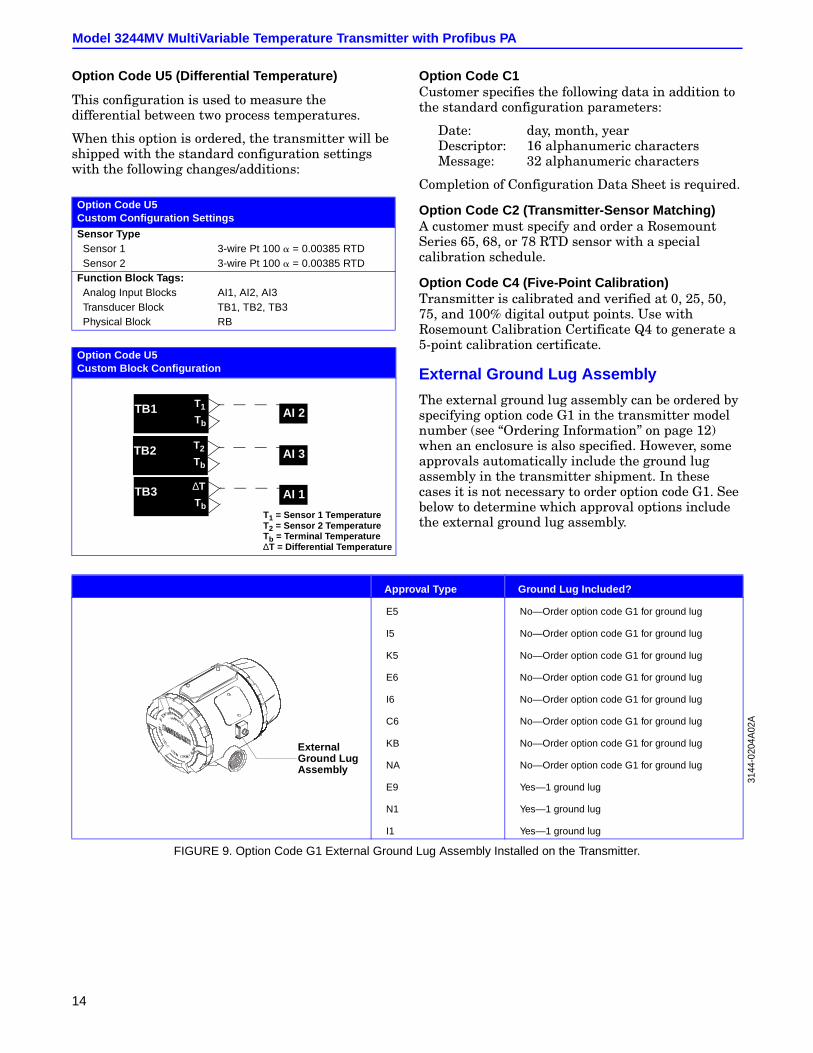
Option Code U5 (Differential Temperature)
This configuration is used to measure the differential between two process temperatures.
When this option is ordered, the transmitter will be shipped with the standard configuration settings with the following changes/additions:
Option Code C1Customer specifies the following data in addition to the standard configuration parameters:
Date: day, month, yearDescriptor: 16 alphanumeric charactersMessage: 32 alphanumeric characters
Completion of Configuration Data Sheet is required.
Option Code C2 (Transmitter-Sensor Matching)A customer must specify and order a Rosemount Series 65, 68, or 78 RTD sensor with a special calibration schedule.
Option Code C4 (Five-Point Calibration)Transmitter is calibrated and verified at 0, 25, 50, 75, and 100% digital output points. Use with Rosemount Calibration Certificate Q4 to generate a 5-point calibration certificate.
External Ground Lug Assembly
The external ground lug assembly can be ordered by specifying option code G1 in the transmitter model number (see “Ordering Information” on page 12) when an enclosure is also specified. However, some approvals automatically include the ground lug assembly in the transmitter shipment. In these cases it is not necessary to order option code G1. See below to determine which approval options include the external ground lug assembly.
FIGURE 9. Option Code G1 External Ground Lug Assembly Installed on the Transmitter.
Option Code U5Custom Configuration Settings
Sensor TypeSensor 1 3-wire Pt 100 a = 0.00385 RTDSensor 2 3-wire Pt 100 a = 0.00385 RTD
Function Block Tags:Analog Input Blocks AI1, AI2, AI3Transducer Block TB1, TB2, TB3Physical Block RB
Option Code U5Custom Block Configuration
T1 = Sensor 1 TemperatureT2 = Sensor 2 TemperatureTb = Terminal Temperature∆T = Differential Temperature
AI 2
AI 1
TB1 T1
Tb
TB2 T2
Tb
TB3 ∆T
Tb
AI 3
Approval Type Ground Lug Included?
E5 No—Order option code G1 for ground lug
I5 No—Order option code G1 for ground lug
K5 No—Order option code G1 for ground lug
E6 No—Order option code G1 for ground lug
I6 No—Order option code G1 for ground lug
C6 No—Order option code G1 for ground lug
KB No—Order option code G1 for ground lug
NA No—Order option code G1 for ground lug
E9 Yes—1 ground lug
N1 Yes—1 ground lug
I1 Yes—1 ground lug
ExternalGround LugAssembly
3144
-020
4A02
A
Rosemount Inc.
15
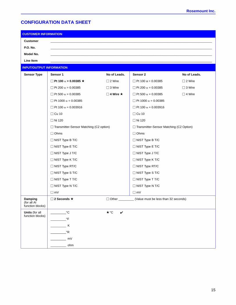
CONFIGURATION DATA SHEET
CUSTOMER INFORMATION
Customer ______________________________________________________________________________________________
P.O. No. ______________________________________________________________________________________________
Model No. ______________________________________________________________________________________________
Line Item ______________________________________________________________________________________________
INPUT/OUTPUT INFORMATION
Sensor Type Sensor 1 No of Leads. Sensor 2 No of Leads.
M Pt 100 a = 0.00385 M 2 Wire M Pt 100 a = 0.00385 M 2 Wire
M Pt 200 a = 0.00385 M 3 Wire M Pt 200 a = 0.00385 M 3 Wire
M Pt 500 a = 0.00385 M 4 Wire M Pt 500 a = 0.00385 M 4 Wire
M Pt 1000 a = 0.00385 M Pt 1000 a = 0.00385
M Pt 100 a = 0.003916 M Pt 100 a = 0.003916
M Cu 10 M Cu 10
M Ni 120 M Ni 120
M Transmitter-Sensor Matching (C2 option) M Transmitter-Sensor Matching (C2 Option)
M Ohms M Ohms
M NIST Type B T/C M NIST Type B T/C
M NIST Type E T/C M NIST Type E T/C
M NIST Type J T/C M NIST Type J T/C
M NIST Type K T/C M NIST Type K T/C
M NIST Type RT/C M NIST Type RT/C
M NIST Type S T/C M NIST Type S T/C
M NIST Type T T/C M NIST Type T T/C
M NIST Type N T/C M NIST Type N T/C
M mV M mV
Damping(for all AIfunction blocks)
M 2 Seconds M Other _________ (Value must be less than 32 seconds)
Units (for allfunction blocks)
_________°C °C
_________°F
_________ K
_________°R
_________ mV
_________ ohm
Rosemount Inc.8200 Market BoulevardChanhassen, MN 55317 USATel 1-800-999-9307Fax (952) 949-7001© 2000 Rosemount, Inc.
PR
INTED
INU.S. A.
Fisher-Rosemount LimitedHeath Place Bognor RegisWest Sussex PO22 9SHEnglandTel 44 (1243) 863 121Fax 44 (1243) 867 5541
Fisher-RosemountSingapore Pte Ltd.1 Pandan CrescentSingapore 128461Tel (65) 777-8211Fax (65) [email protected]
http://www.rosemount.com
¢00813-0100-4769-¤00813-0100-4799 Rev. AA 04/00
Rosemount, the Rosemount logotype, Complete Point Solutions, and MultiVariable (MV) areregistered trademarks of Rosemount Inc.Teflon is a registered trademark of E.I. du Pont de Nemours & Co.
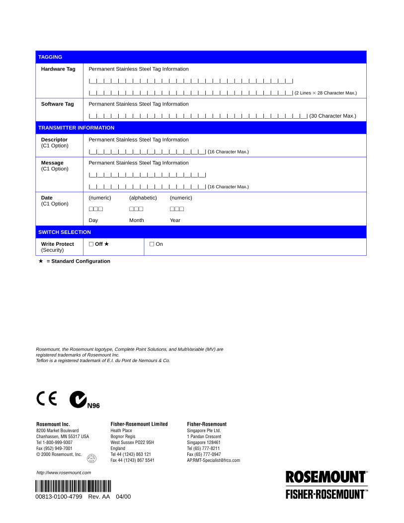
TAGGING
Hardware Tag Permanent Stainless Steel Tag Information
|__|__|__|__|__|__|__|__|__|__|__|__|__|__|__|__|__|__|__|__|__|__|__|__|__|__|__|__|
|__|__|__|__|__|__|__|__|__|__|__|__|__|__|__|__|__|__|__|__|__|__|__|__|__|__|__|__| (2 Lines 3 28 Character Max.)
Software Tag Permanent Stainless Steel Tag Information
|__|__|__|__|__|__|__|__|__|__|__|__|__|__|__|__|__|__|__|__|__|__|__|__|__|__|__|__|__|__| (30 Character Max.)
TRANSMITTER INFORMATION
Descriptor(C1 Option)
Permanent Stainless Steel Tag Information
|__|__|__|__|__|__|__|__|__|__|__|__|__|__|__|__| (16 Character Max.)
Message(C1 Option)
Permanent Stainless Steel Tag Information
|__|__|__|__|__|__|__|__|__|__|__|__|__|__|__|__|
|__|__|__|__|__|__|__|__|__|__|__|__|__|__|__|__| (16 Character Max.)
Date(C1 Option)
(numeric) (alphabetic) (numeric)
MMM MMM MMM
Day Month Year
SWITCH SELECTION
Write Protect(Security)
M Off M On
= Standard Configuration