Embed Size (px)
Citation preview
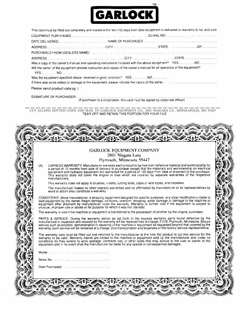
2601 NIAGARA LANE, PLYMOUTH, MN 55447Phone: (763) 553-1935
Fax (763) 553-7765
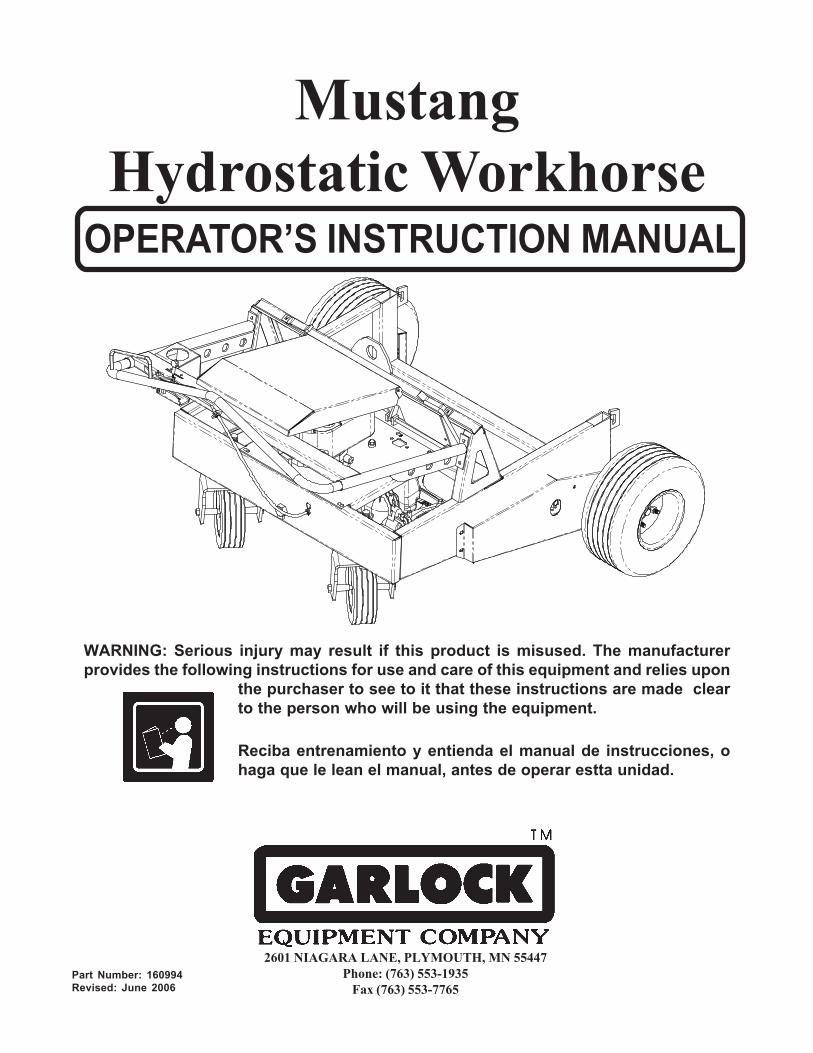
MustangHydrostatic Workhorse
Part Number: 160994Revised: June 2006
Reciba entrenamiento y entienda el manual de instrucciones, ohaga que le lean el manual, antes de operar estta unidad.
WARNING: Serious injury may result if this product is misused. The manufacturerprovides the following instructions for use and care of this equipment and relies upon
the purchaser to see to it that these instructions are made clearto the person who will be using the equipment.
OPERATOR’S INSTRUCTION MANUAL
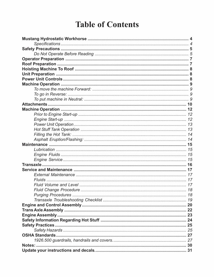
Table of ContentsMustang Hydrostatic Workhorse ...................................................................................... 4
Specifications ............................................................................................................. 4Safety Precautions ............................................................................................................. 5
Do Not Operate Before Reading ................................................................................ 5Operator Preparation ......................................................................................................... 7Roof Preparation ................................................................................................................ 7Hoisting Machine To Roof ................................................................................................. 8Unit Preparation ................................................................................................................. 8Power Unit Controls ........................................................................................................... 8Machine Operation ............................................................................................................. 9
To move the machine Forward: .................................................................................. 9To go in Reverse: ....................................................................................................... 9To put machine in Neutral: ......................................................................................... 9
Attachments ...................................................................................................................... 10Machine Operation ........................................................................................................... 12
Prior to Engine Start-up ............................................................................................ 12Engine Start-up ........................................................................................................ 12Power Unit Operation................................................................................................ 13Hot Stuff Tank Operation .......................................................................................... 13Filling the Hot Tank: ................................................................................................. 14Asphalt Eruption/Flashing: ....................................................................................... 14
Maintenance ..................................................................................................................... 15Lubrication ............................................................................................................... 15Engine Fluids ........................................................................................................... 15Engine Service ......................................................................................................... 15
Transaxle ........................................................................................................................... 16Service and Maintenance ................................................................................................ 17
External Maintenance .............................................................................................. 17Fluids ....................................................................................................................... 17Fluid Volume and Level ........................................................................................... 17Fluid Change Procedure .......................................................................................... 18Purging Procedures ................................................................................................. 18Transaxle Troubleshooting Checklist ....................................................................... 19
Engine and Control Assembly......................................................................................... 20Trans Axle Assembly ........................................................................................................ 22Engine Assembly .............................................................................................................. 23Safety Information Regarding Hot Stuff ......................................................................... 24Safety Practices ................................................................................................................ 25
Safety Hazards ......................................................................................................... 25OSHA Standards............................................................................................................... 27
1926.500 guardrails, handrails and covers............................................................... 27Notes: ................................................................................................................................ 30Update your instructions and decals.............................................................................. 31
4
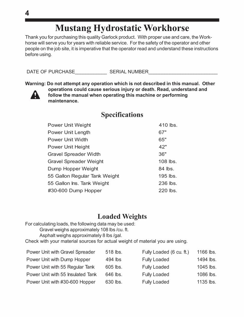
SpecificationsthgieWtinUrewoP .sbl014
htgneLtinUrewoP "76htdiWtinUrewoP "56
thgieHtinUrewoP "24htdiWredaerpSlevarG "63
thgieWredaerpSlevarG .sbl801thgieWreppoHpmuD .sbl48
thgieWknaTralugeRnollaG55 .sbl591thgieWknaT.snInollaG55 .sbl632
reppoHpmuD006-03# .sbl022
Mustang Hydrostatic WorkhorseThank you for purchasing this quality Garlock product. With proper use and care, the Work-horse will serve you for years with reliable service. For the safety of the operator and otherpeople on the job site, it is imperative that the operator read and understand these instructionsbefore using.
DATE OF PURCHASE____________ SERIAL NUMBER__________________________
redaerpSlevarGhtiwtinUrewoP .sbl815 ).tf.uc6(dedaoLylluF .sbl6611reppoHpmuDhtiwtinUrewoP sbl494 dedaoLylluF .sbl4941
knaTralugeR55htiwtinUrewoP .sbl506 dedaoLylluF .sbl5401knaTdetalusnI55htiwtinUrewoP .sbl646 dedaoLylluF .sbl6801reppoH006-03#htiwtinUrewoP .sbl036 dedaoLylluF .sbl5311
Loaded WeightsFor calculating loads, the following data may be used:
Gravel weighs approximately 108 lbs /cu. ft.Asphalt weighs approximately 8 lbs /gal.
Check with your material sources for actual weight of material you are using.
Warning: Do not attempt any operation which is not described in this manual. Otheroperations could cause serious injury or death. Read, understand andfollow the manual when operating this machine or performingmaintenance.
5
Safety PrecautionsDo Not Operate Before Reading
INTENDED USE: This machine is intended to be used as a: felt carrier, insulation carrier,rubbish and gravel carrier, hot stuff carrier, gravel spreader and hot stuff dispenser. Foruse on flat level roofs only. Any other use of this equipment voids the manufacturer's war-ranty and is the sole responsibility of the owner/user, should damage or injury occur.
Do not hoist the Workhorse with #30 debris hopper or hot stuff tank installed.
Do not hoist the Workhorse with gravel spreader or dump hopper loaded.
For use on flat, level roofs only.
Keep other people clear of machine during operation.
Do not operate without a perimeter warning line system.
Do not operate within ten feet of roof edge (or within six feet if operating parallel to edge).
Do not operate without spotter.
Guard all openings in the roof.
Keep the equipment in good operating condition.
Do not operate the machine if it is damaged. Repairs must be made by a qualified me-chanic. Replace damaged components.
Do not modify the machine. Do not operate a machine that has been modified.
Wear proper attire: Long sleeve cotton shirt, buttoned at the cuff, long pants without cuffs,gloves (cotton or leather) that cover your wrist and fit snug at cuff, and high top safetyshoes.
Avoid slick areas on the roof to prevent slipping.
Do not operate this machine if you are under the influence of alcohol, marijuana, or drugsthat could impair judgment and ability.
6The owner or operator must see that all warning decals are in place and legible. Write toGarlock Equipment Co. for replacement decals and instructions if needed.
Operator must be trained to do the specific job before operating equipment on an actualjob.
Do not exceed weight carrying capacity of the deck. Check with owner or architect for deckcapacity.
Never tip dispenser when filling, transporting or dispensing hot stuff.
Never stand downwind of draincock when filling or draining hot tank. Fumes and hot stuffwill blow on windy days.
Stand clear of the path of discharging hot material.
Keep external ignition sources away from hot stuff.
Check material temperature with an accurate thermometer.
The following information is quoted from OSHA:Safety and Health Standards Digest, OSHA 2202 revised September 1983.
It is usually a good idea for the employer to keep a record of all safety and health training.Records can provide evidence of the employer’s good faith and compliance with OSHAstandards. Documentation can also supply an answer to one of the first questions anaccident investigator will ask: “Was the injured party trained to do the job?”
Training in the proper performance of a job is time and money well spent and the employermight regard it as an investment rather than an expense. An effective program of safetyand health training for workers can result in fewer accidents and illnesses, better moraleand lower insurance premiums and other benefits.
Readers with questions concerning worker safety and health training should contact theirregional OSHA office.
7
Operator PreparationRead Instruction Manual
Reading the instructions completely is the first step to safe operation. An uninformedoperator can subject himself and others to death or serious injury.
Wear Proper AttireSafety glasses are recommended and must be worn if any roof cutting or scraping is beingdone in the vicinity. Safety glasses and/or face shield are also necessary when workingwith hot stuff. Wear properly fitting clothes. Tight clothing can restrict movement and slowdown reaction time in a dangerous situation. Loose fitting clothing can be dangerous andcause serious injury if it gets caught in moving mechanical parts. Wear a long-sleevedshirt, buttoned at the cuffs, safety shoes, and pants without cuffs. Operator must wear hardhat when work is being done at a higher level
Roof PreparationInspect Roof Deck
Before allowing equipment and personnel access to roof, make certain roof is strongenough to support the weight. Check load limits of deck with owner, builder or architect.Clear the work area of all potentially dangerous obstacles that could cause personal injuryto the operator or others. Keep unauthorized people away from construction area. Check tosee that all roof openings are guarded to protect against falls.
Warning Line SystemOperation of Workhorse must be in compliance with Federal OSHA standards governingsafety perimeters with respect to the use of power equipment. When operating parallel toroof edge, warning line system must be at least six feet from edge. When operating per-pendicular to edge, warning line must be ten feet from roof edge. For specific informationon warning lines, the use of guard rails and motion-stopping –safety systems, refer tosection on OSHA Law.
8
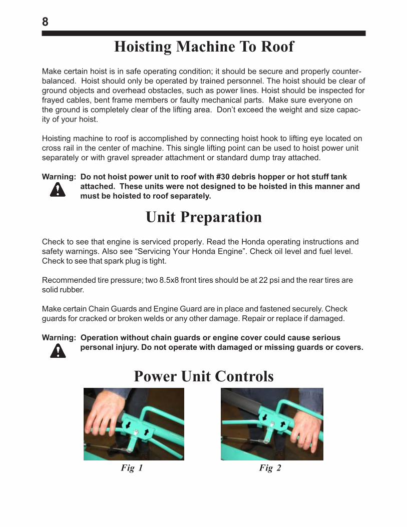
Hoisting Machine To RoofMake certain hoist is in safe operating condition; it should be secure and properly counter-balanced. Hoist should only be operated by trained personnel. The hoist should be clear ofground objects and overhead obstacles, such as power lines. Hoist should be inspected forfrayed cables, bent frame members or faulty mechanical parts. Make sure everyone onthe ground is completely clear of the lifting area. Don’t exceed the weight and size capac-ity of your hoist.
Hoisting machine to roof is accomplished by connecting hoist hook to lifting eye located oncross rail in the center of machine. This single lifting point can be used to hoist power unitseparately or with gravel spreader attachment or standard dump tray attached.
Warning: Do not hoist power unit to roof with #30 debris hopper or hot stuff tankattached. These units were not designed to be hoisted in this manner andmust be hoisted to roof separately.
Unit PreparationCheck to see that engine is serviced properly. Read the Honda operating instructions andsafety warnings. Also see “Servicing Your Honda Engine”. Check oil level and fuel level.Check to see that spark plug is tight.
Recommended tire pressure; two 8.5x8 front tires should be at 22 psi and the rear tires aresolid rubber.
Make certain Chain Guards and Engine Guard are in place and fastened securely. Checkguards for cracked or broken welds or any other damage. Repair or replace if damaged.
Warning: Operation without chain guards or engine cover could cause seriouspersonal injury. Do not operate with damaged or missing guards or covers.
Power Unit Controls
Fig 1 Fig 2
9
The Gravel Dispenser Lever is located on the right side of the Power Unit Handle. Pulling backon the handle opens the discharge door of gravel dispenser. Pushing forward will close door.For detailed Gravel Spreader installation instructions, see “Gravel Spreader Attachment”section in this manual.The Dump Hopper (or Felt Carrier) release lever is located just to the right of the enginecover. Pull back to release the hopper lock. Be sure hopper is locked in down (load)position before leaving dump site. For detailed Dump Hopper installation instructions, see“Dump Hopper Attachment” section in this manual.
The #30 Debris Hopper Dump Lever is located beneath the rear and on both sides of theDebris Hopper. The Debris Hopper lock is disengaged when the dump lever is lifted. The lockis automatically engaged when the Debris Hopper is set back down. For detailed DebrisHopper installation instructions, see “#30 Debris Hopper Attachment” section in thismanual.
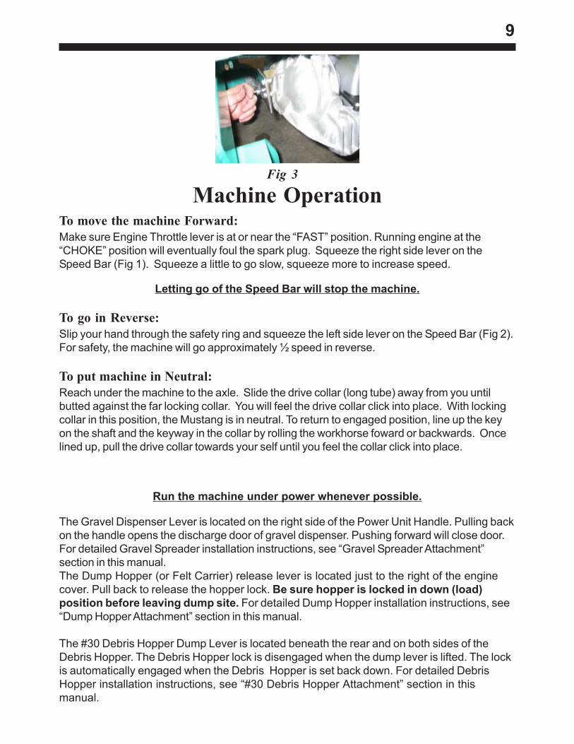
Machine OperationTo move the machine Forward:Make sure Engine Throttle lever is at or near the “FAST” position. Running engine at the“CHOKE” position will eventually foul the spark plug. Squeeze the right side lever on theSpeed Bar (Fig 1). Squeeze a little to go slow, squeeze more to increase speed.
Letting go of the Speed Bar will stop the machine.
To go in Reverse:Slip your hand through the safety ring and squeeze the left side lever on the Speed Bar (Fig 2).For safety, the machine will go approximately ½ speed in reverse.
To put machine in Neutral:Reach under the machine to the axle. Slide the drive collar (long tube) away from you untilbutted against the far locking collar. You will feel the drive collar click into place. With lockingcollar in this position, the Mustang is in neutral. To return to engaged position, line up the keyon the shaft and the keyway in the collar by rolling the workhorse foward or backwards. Oncelined up, pull the drive collar towards your self until you feel the collar click into place.
Run the machine under power whenever possible.
Fig 3
10
AttachmentsWarning: On wide span decks, check load limits with builder, owner, or architect
before setting up unit.
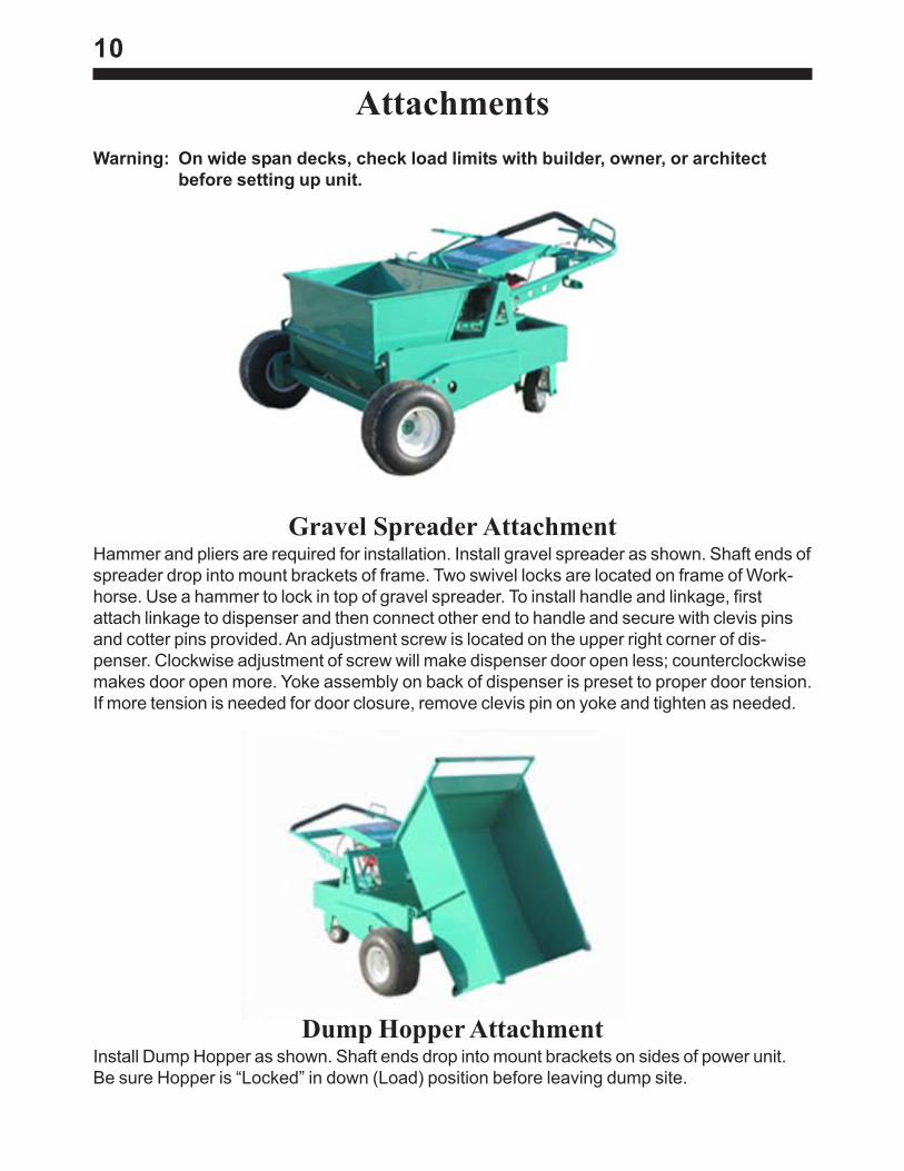
Gravel Spreader AttachmentHammer and pliers are required for installation. Install gravel spreader as shown. Shaft ends ofspreader drop into mount brackets of frame. Two swivel locks are located on frame of Work-horse. Use a hammer to lock in top of gravel spreader. To install handle and linkage, firstattach linkage to dispenser and then connect other end to handle and secure with clevis pinsand cotter pins provided. An adjustment screw is located on the upper right corner of dis-penser. Clockwise adjustment of screw will make dispenser door open less; counterclockwisemakes door open more. Yoke assembly on back of dispenser is preset to proper door tension.If more tension is needed for door closure, remove clevis pin on yoke and tighten as needed.
Dump Hopper AttachmentInstall Dump Hopper as shown. Shaft ends drop into mount brackets on sides of power unit.Be sure Hopper is “Locked” in down (Load) position before leaving dump site.
11
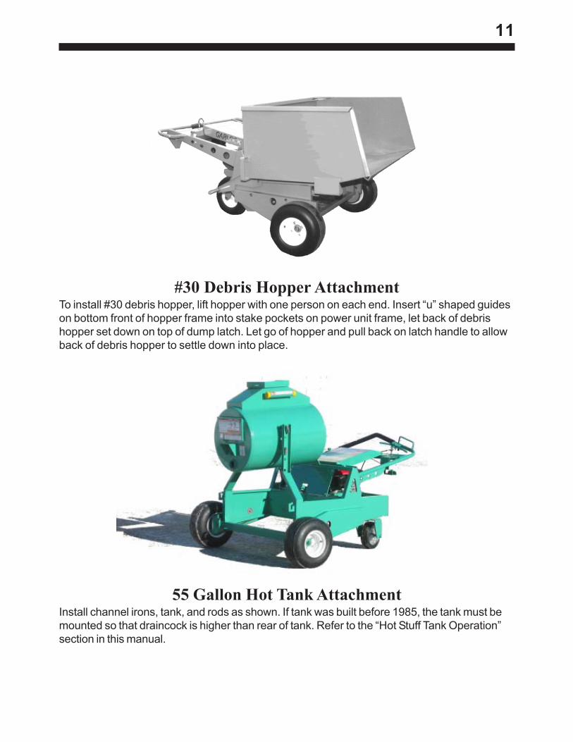
#30 Debris Hopper AttachmentTo install #30 debris hopper, lift hopper with one person on each end. Insert “u” shaped guideson bottom front of hopper frame into stake pockets on power unit frame, let back of debrishopper set down on top of dump latch. Let go of hopper and pull back on latch handle to allowback of debris hopper to settle down into place.
55 Gallon Hot Tank AttachmentInstall channel irons, tank, and rods as shown. If tank was built before 1985, the tank must bemounted so that draincock is higher than rear of tank. Refer to the “Hot Stuff Tank Operation”section in this manual.
12
Machine OperationPrior to Engine Start-up
After reading through all of the instructions, the Mustang Hydrostatic Workhorse should beready for operation. When operating the machine for the first time, position the machine on theground or in an open level area away from obstructions and roof edges. Start engine and allowto warm up for five minutes. With no load on the Workhorse, practice maneuvering the ma-chine by operating controls as described in the “Power Unit Controls” section of this manual.Check brake operation. When the Speed Bar is released the Workhorse should stop instantly.If not, do not operate machine until repairs or adjustments are completed.
Engine Start-up
See illustration for lever locations.
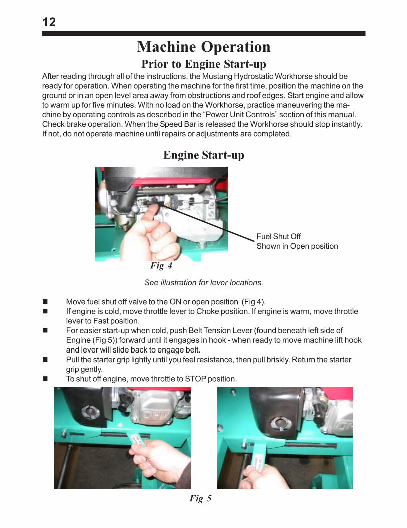
Move fuel shut off valve to the ON or open position (Fig 4).If engine is cold, move throttle lever to Choke position. If engine is warm, move throttlelever to Fast position.For easier start-up when cold, push Belt Tension Lever (found beneath left side ofEngine (Fig 5)) forward until it engages in hook - when ready to move machine lift hookand lever will slide back to engage belt.Pull the starter grip lightly until you feel resistance, then pull briskly. Return the startergrip gently.To shut off engine, move throttle to STOP position.
Fuel Shut OffShown in Open position
Fig 4
Fig 5
13
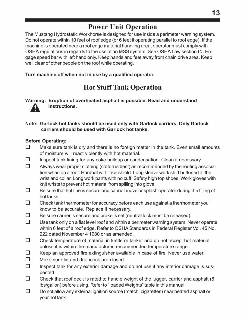
Power Unit OperationThe Mustang Hydrostatic Workhorse is designed for use inside a perimeter warning system.Do not operate within 10 feet of roof edge (or 6 feet if operating parallel to roof edge). If themachine is operated near a roof edge material handling area, operator must comply withOSHA regulations in regards to the use of an MSS system. See OSHA Law section IX. En-gage speed bar with left hand only. Keep hands and feet away from chain drive area. Keepwell clear of other people on the roof while operating.
Turn machine off when not in use by a qualified operator.
Hot Stuff Tank Operation
Warning: Eruption of overheated asphalt is possible. Read and understandinstructions.
Note: Garlock hot tanks should be used only with Garlock carriers. Only Garlockcarriers should be used with Garlock hot tanks.
Before Operating:Make sure tank is dry and there is no foreign matter in the tank. Even small amountsof moisture will react violently with hot material.Inspect tank lining for any coke buildup or condensation. Clean if necessary.Always wear proper clothing (cotton is best) as recommended by the roofing associa-tion when on a roof: Hardhat with face shield. Long sleeve work shirt buttoned at thewrist and collar. Long work pants with no cuff. Safety high top shoes. Work gloves withknit wrists to prevent hot material from spilling into glove.Be sure that hot line is secure and cannot move or splash operator during the filling ofhot tanks.Check tank thermometer for accuracy before each use against a thermometer youknow to be accurate. Replace if necessary.Be sure carrier is secure and brake is set (neutral lock must be released).Use tank only on a flat level roof and within a perimeter warning system. Never operatewithin 6 feet of a roof edge. Refer to OSHA Standards in Federal Register Vol. 45 No.222 dated November 4 1980 or as amended.Check temperature of material in kettle or tanker and do not accept hot materialunless it is within the manufactures recommended temperature range.Keep an approved fire extinguisher available in case of fire. Never use water.Make sure lid and draincock are closed.Inspect tank for any exterior damage and do not use if any interior damage is sus-pected.Check that roof deck is rated to handle weight of the lugger, carrier and asphalt (8lbs/gallon) before using. Refer to “loaded Weights” table in this manual.Do not allow any external ignition source (match, cigarettes) near heated asphalt oryour hot tank.
14
Filling the Hot Tank:Never stand down wind of hot source when filling as fumes and/or hot material may causeinjury.
Do not fill hot tank more than ¾ full to avoid the splashing of material.
Warning: Never fill hot tank with overheated material. Overheated asphalt may erupt.Flash points vary and proper temperature must be obtained from theasphalt manufacturer.
Asphalt Eruption/Flashing:An eruption requires these three components to happen.
Fuel: Flammable gasses from overheated or poorly refined hot material.Air: Can come from tipping, sloshing or discharging asphalt with lid open.Ignition: Overheated material or material in tank with lower flash point (coked
material on tank walls, trash, cigarettes or matches).Obtain information from your supplier of hot material for specific instructions on ways toavoid eruption or flashing of their particular product.
Transporting and Draining Hot Tank:Transport hot tank very smoothly and slowly so splashing can’t occur. Check pathfor obstacles and bumps and approach with caution. Do not make sudden stops orturns. Avoid transporting hot stuff on ramps. Keep lid closed during transporting and drain-ing. Never tip hot tank while transporting, filling, or draining. Tip only when tank is emptyand cool. Be sure brake is set (neutral lock released) before discharging Hot material.Never stand downwind from draincock while discharging as wind may blow fumes or hotmaterial. Stand clear of the path of discharging hot material.
Warning: Do not attempt any operation which is not described in this manual. Otheroperations could cause serious injury or death. Read, understand andfollow the manual when operating this machine or performingmaintenance.
15
MaintenanceNote: Disconnect spark plug wire before working on the machine.
LubricationLubrication recommendations are as follows: Grease roller bearings on wheels weekly oras needed. Zerks for 8.5x8 wheels are located on the hub between the tire and chain drivesprocket. Also grease swivel caster and speed bar. Zerks are provided for both. Bearings ontransaxle assembly are sealed and do not require grease. Dispenser handles should begreased at rotation points (zerks provided). Also oil pivot points of linkages. Roller chainshould be lubricated with spray chain lube such as PJI Blue Label or a quality bar oil. Cleanmonthly with a wire brush.
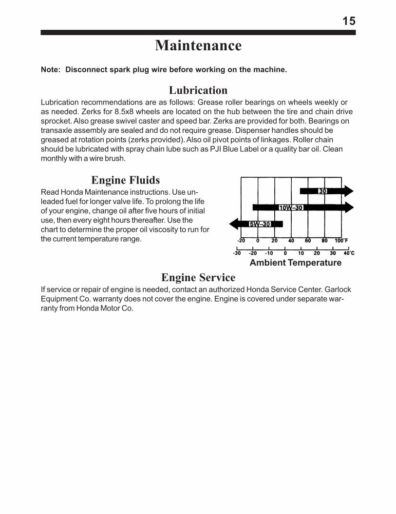
Engine FluidsRead Honda Maintenance instructions. Use un-leaded fuel for longer valve life. To prolong the lifeof your engine, change oil after five hours of initialuse, then every eight hours thereafter. Use thechart to determine the proper oil viscosity to run forthe current temperature range.
Ambient TemperatureEngine Service
If service or repair of engine is needed, contact an authorized Honda Service Center. GarlockEquipment Co. warranty does not cover the engine. Engine is covered under separate war-ranty from Honda Motor Co.
16
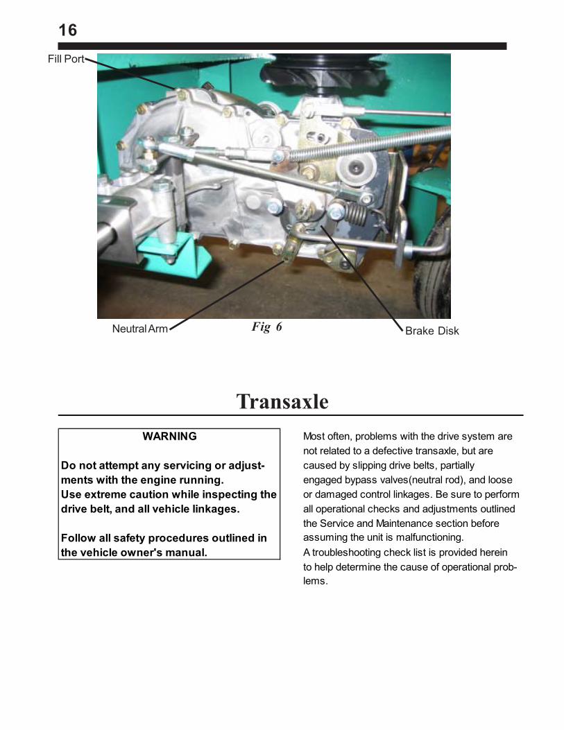
WARNING Most often, problems with the drive system arenot related to a defective transaxle, but are
Do not attempt any servicing or adjust- caused by slipping drive belts, partially ments with the engine running. engaged bypass valves(neutral rod), and looseUse extreme caution while inspecting the or damaged control linkages. Be sure to performdrive belt, and all vehicle linkages. all operational checks and adjustments outlined
the Service and Maintenance section beforeFollow all safety procedures outlined in assuming the unit is malfunctioning. the vehicle owner's manual. A troubleshooting check list is provided herein
to help determine the cause of operational prob-lems.
Transaxle
Fig 6 Brake DiskNeutral Arm
Fill Port
17
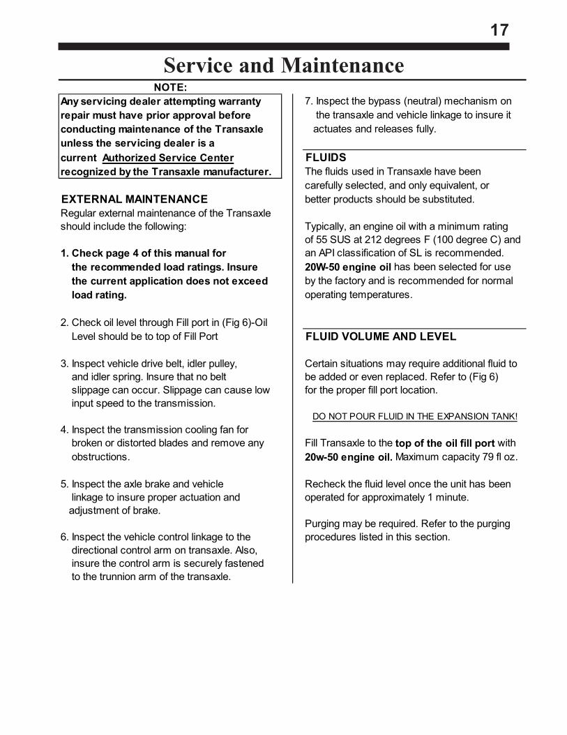
NOTE:Any servicing dealer attempting warranty 7. Inspect the bypass (neutral) mechanism on repair must have prior approval before the transaxle and vehicle linkage to insure itconducting maintenance of the Transaxle actuates and releases fully.unless the servicing dealer is acurrent Authorized Service Center FLUIDSrecognized by the Transaxle manufacturer. The fluids used in Transaxle have been
carefully selected, and only equivalent, orEXTERNAL MAINTENANCE better products should be substituted.Regular external maintenance of the Transaxleshould include the following: Typically, an engine oil with a minimum rating
of 55 SUS at 212 degrees F (100 degree C) and1. Check page 4 of this manual for an API classification of SL is recommended. the recommended load ratings. Insure 20W-50 engine oil has been selected for use the current application does not exceed by the factory and is recommended for normal load rating. operating temperatures.
2. Check oil level through Fill port in (Fig 6)-Oil Level should be to top of Fill Port FLUID VOLUME AND LEVEL
3. Inspect vehicle drive belt, idler pulley, Certain situations may require additional fluid to and idler spring. Insure that no belt be added or even replaced. Refer to (Fig 6) slippage can occur. Slippage can cause low for the proper fill port location. input speed to the transmission.
DO NOT POUR FLUID IN THE EXPANSION TANK!4. Inspect the transmission cooling fan for broken or distorted blades and remove any Fill Transaxle to the top of the oil fill port with obstructions. 20w-50 engine oil. Maximum capacity 79 fl oz.
5. Inspect the axle brake and vehicle Recheck the fluid level once the unit has been linkage to insure proper actuation and operated for approximately 1 minute. adjustment of brake.
Purging may be required. Refer to the purging6. Inspect the vehicle control linkage to the procedures listed in this section. directional control arm on transaxle. Also, insure the control arm is securely fastened to the trunnion arm of the transaxle.
Service and Maintenance
External MaintenanceFluids
Fluid Volume and Level
18
FLUID CHANGE PROCEDUREThis transaxle is factory filled, sealed and does 6. Remove the tank and drain the oil from thenot require oil maintenance. However, in the tank. DO NOT remove the vent cap from theevent of oil contamination or degradation, oil tank. DO NOT remove the tank hose oraddition or change may alleviate certain perfor- o-ring unless a replacement is needed.mance problems.
7. Install the tank by first inserting the hose1. Remove the transaxle from the vehicle. into the opening in the expansion tank.
Push the tank opening over the o-ring to en-2. Clean the expansion tank and oil port sure a proper seal. areas of any debris.
8. Install the tank support bracket and self tap-3. Remove the oil fill port fitting. ping bolt making sure not to cross thread
the bolt. Torque the bolt to 42-65 LB-IN4. Position the transaxle so the oil will drain completely out of the housing.
9. Fill the transaxle at the oil fill port shown in5. After all the oil is drained from the transaxle, (Fig 6). Oil level should be to the top of the remove the expansion tank by removing the Fill Port self tapping bolt (10-32x1/2) that holds the tank support bracket. 10. Install the oil fill port fitting.
PURGING PROCEDURESDue to the effects air has on efficiency in The following procedures should be performed hydrostatic drive applications, it is critical that it with the vehicle drive wheels off the ground,be purged from the system. then repeated under normal operating conditions.
These purge procedures should be implemented 1.With the bypass valve open and the engine any time a hydrostatic system has been opened running, slowly move the directional controlto facilitate maintenance or any additional oil has in both forward and reverse directions been added to the system. (5 to 6 times), as air is purged from the unit,
the oil level will drop.Air creates inefficiency because it's compressionand expansion rate is higher than that of the oil 2. With the bypass valve closed and the engineapproved for use in hydrostatic drive systems. running, slowly move the directional control in
both forward and reverse directions The resulting symptoms in hydrostatic systems (5 to 6 times). Check oil level, and add oil asmay be: required after stopping engine.
1. Noisy operation or lack of power or drive 3. It may be necessary to repeat Steps 1 and 2 after short term operation. until all the air is completely purged from the
system. When the transaxle moves forward2. High operation temperature and excessive and reverse at normal speed purging is expansion of oil. complete.
Before starting, make sure the transaxle is filledwith oil to the proper level. If it is not,fill to the specification described above in"Fluid Volume And Level" and (Fig 6)
Fluid Change ProcedurePurging Procedures
19
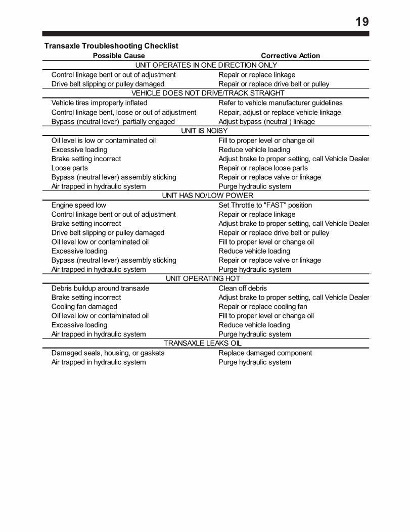
Transaxle Troubleshooting ChecklistPossible Cause Corrective Action
UNIT OPERATES IN ONE DIRECTION ONLY Control linkage bent or out of adjustment Repair or replace linkage Drive belt slipping or pulley damaged Repair or replace drive belt or pulley VEHICLE DOES NOT DRIVE/TRACK STRAIGHT Vehicle tires improperly inflated Refer to vehicle manufacturer guidelines Control linkage bent, loose or out of adjustment Repair, adjust or replace vehicle linkage Bypass (neutral lever) partially engaged Adjust bypass (neutral ) linkage UNIT IS NOISY Oil level is low or contaminated oil Fill to proper level or change oil Excessive loading Reduce vehicle loading Brake setting incorrect Adjust brake to proper setting, call Vehicle Dealer Loose parts Repair or replace loose parts Bypass (neutral lever) assembly sticking Repair or replace valve or linkage Air trapped in hydraulic system Purge hydraulic system UNIT HAS NO/LOW POWER Engine speed low Set Throttle to "FAST" position Control linkage bent or out of adjustment Repair or replace linkage Brake setting incorrect Adjust brake to proper setting, call Vehicle Dealer Drive belt slipping or pulley damaged Repair or replace drive belt or pulley Oil level low or contaminated oil Fill to proper level or change oil Excessive loading Reduce vehicle loading Bypass (neutral lever) assembly sticking Repair or replace valve or linkage Air trapped in hydraulic system Purge hydraulic system UNIT OPERATING HOT Debris buildup around transaxle Clean off debris Brake setting incorrect Adjust brake to proper setting, call Vehicle Dealer Cooling fan damaged Repair or replace cooling fan Oil level low or contaminated oil Fill to proper level or change oil Excessive loading Reduce vehicle loading Air trapped in hydraulic system Purge hydraulic system TRANSAXLE LEAKS OIL Damaged seals, housing, or gaskets Replace damaged component Air trapped in hydraulic system Purge hydraulic system
Transaxle Troubleshooting Checklist
20
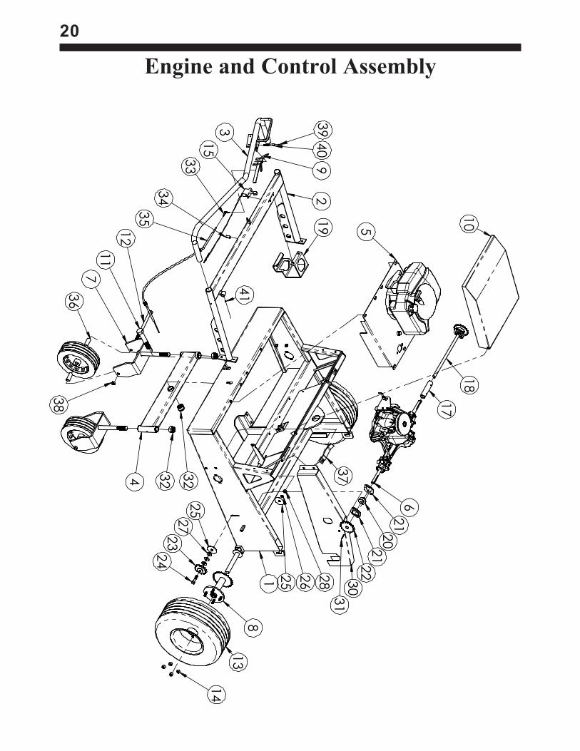
Engine and Control Assembly
25
27
23
24
8
13
14
1 25
26
28 30
22
21
20
21
6
37
5
10
17
18
19
239
40
9
3
15
33
34
35
12
36
7
4 32
32
11
38
41
31

21
ITEM#QTY.PART#
DESCRIPTIO
NITEM#QTY.PART#
DESCRIPTIO
N
11
40
47
82
FR
AM
E W
ELD
ME
NT
23
21
11
24
15
0E
15
IDLE
R S
PR
OC
KE
T
21
40
47
84
HA
ND
LE
WE
LD
ME
NT
24
21
00
03
5H
HC
S 1
/2 X
2-1
/4
31
40
47
85
HA
ND
LE
BA
R W
DM
T.
25
41
00
19
61
/2 X
2.5
OD
WA
SH
ER
41
40
47
86
RE
AR
AX
LE
ASSE
MB
LY
26
21
00
09
51
/2 L
OC
K W
ASH
ER
51
40
47
87
EN
GIN
E A
SSE
MB
LY
27
61
00
45
71
/2 F
LA
T W
ASH
ER
61
40
47
88
TR
AN
SA
XLE
ASSE
MB
LY
28
21
00
17
01
/2-1
3 N
UT
72
40
47
89
CA
STE
R W
ELD
ME
NT
29
14
21
34
9C
HA
IN G
UA
RD
-LE
FT
82
40
47
90
FR
ON
T H
UB
WD
MT.
30
14
21
35
0C
HA
IN G
UA
RD
-RH
91
40
47
91
F/R
LE
VE
R3
14
11
00
91
KE
Y, 3
/16
X 1
1/2
10
14
21
34
3E
NG
INE
CO
VE
R3
23
10
05
93
1.0
INSE
RT N
UT
11
11
00
65
5H
HC
S 1
X 5
-1/2
33
11
11
24
5R
OD
EN
D .2
5 M
ALE
12
21
00
90
2H
HC
S 5
/8 X
93
41
15
20
12
CA
BLE
CLA
MP
NO
.6
13
21
40
00
5W
HE
EL 1
8/8
.50
35
21
30
09
0P
USH
ON
CA
BLE
14
81
00
13
5LU
G- .5
0-2
0 X
.75
36
44
21
36
4SP
AC
ER
15
11
30
13
9TH
RO
TTLE
ASSE
MB
LY
37
24
19
01
3H
OLD
DO
WN
16
21
40
51
1W
HE
EL 1
2x3
x3
/43
82
10
00
81
5/8
JA
M N
UT
17
14
21
35
3SH
AFT C
OLLA
R3
91
15
00
13
GR
EA
SE
ZE
RK
3/1
6
18
14
21
36
3A
XLE
SH
AFT
40
11
00
02
2G
RE
ASE
BO
LT-.3
8
19
14
21
36
5C
UP
HO
LD
ER
41
11
50
01
3G
RE
ASE
ZE
RK
20
21
10
50
0B
EA
RIN
G 3
/4 ID
*42
11
11
24
4B
ELT
21
41
10
50
1SP
HE
RE
BR
NG
FLN
G*4
32
11
12
47
DR
IVE
CH
AIN
22
21
11
24
3SP
KT. C
PLG
. 1" (1
6t)
* IND
EC
ATE
S IT
EM
NO
T S
HO
WN
22
11
5
4
109
6
3
8
2
7
12
1
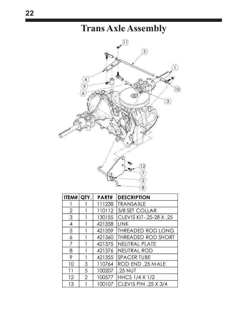
Trans Axle Assembly
ITEM# QTY. PART# DESCRIPTION
1 1 111238 TRANSAXLE
2 1 110112 3/8 SET COLLAR
3 1 130155 CLEVIS KIT-.25-28 X .25
4 1 421358 LINK
5 1 421359 THREADED ROD LONG
6 1 421360 THREADED ROD SHORT
7 1 421375 NEUTRAL PLATE
8 1 421376 NEUTRAL ROD
9 1 421355 SPACER TUBE
10 3 110764 ROD END .25 MALE
11 5 100207 .25 NUT
12 2 100577 HHCS 1/4 X 1/2
13 1 100107 CLEVIS PIN .25 X 3/4
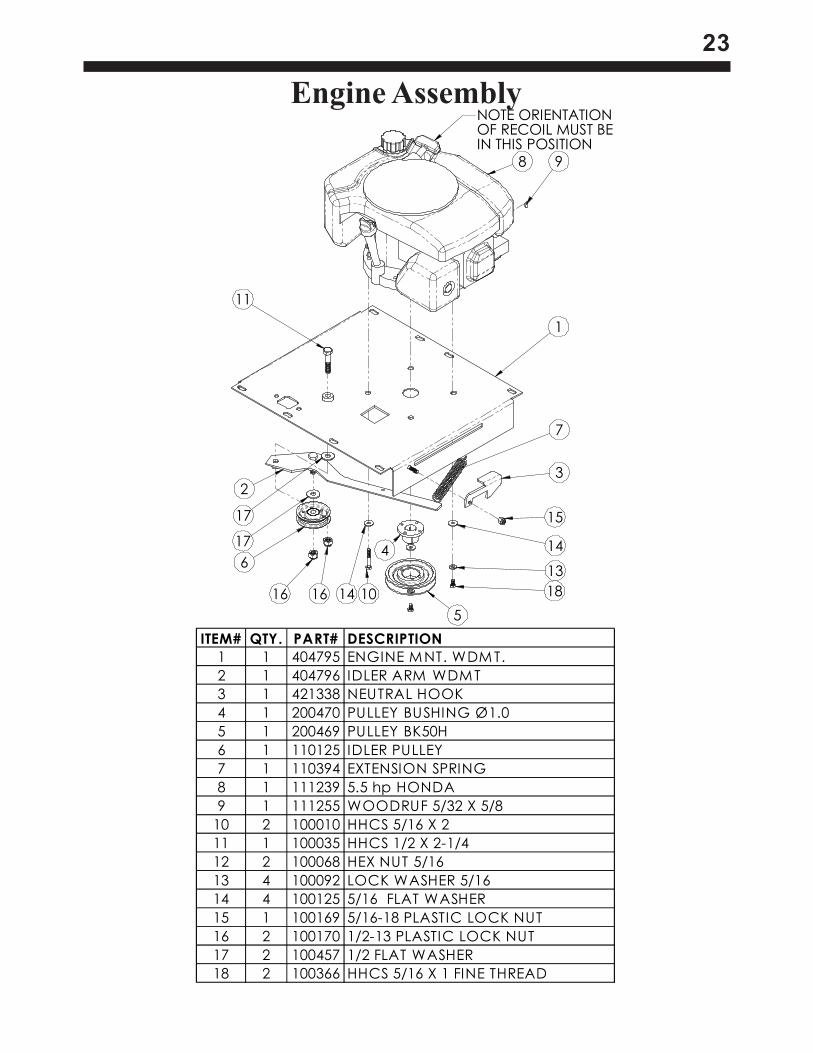
23
NOTE ORIENTATION
OF RECOIL MUST BE
IN THIS POSITION
8 9
1
3
7
15
14
13
18
5
4
10141616
6
17
2
17
11
Engine Assembly
ITEM# QTY. PART# DESCRIPTION
1 1 404795 ENGINE MNT. WDM T.
2 1 404796 IDLER ARM WDMT
3 1 421338 NEUTRAL HOOK
4 1 200470 PULLEY BUSHING Ø1.0
5 1 200469 PULLEY BK50H
6 1 110125 IDLER PULLEY
7 1 110394 EXTENSION SPRING
8 1 111239 5.5 hp HONDA
9 1 111255 WOODRUF 5/32 X 5/8
10 2 100010 HHCS 5/16 X 2
11 1 100035 HHCS 1/2 X 2-1/4
12 2 100068 HEX NUT 5/16
13 4 100092 LOCK WASHER 5/16
14 4 100125 5/16 FLAT WASHER
15 1 100169 5/16-18 PLASTIC LOCK NUT
16 2 100170 1/2-13 PLASTIC LOCK NUT
17 2 100457 1/2 FLAT WASHER
18 2 100366 HHCS 5/16 X 1 FINE THREAD
24
Safety Information Regarding Hot StuffHot Stuff Burns
Hot stuff burns are the most common types of injury that Roofers have. Using good work practices can helpprevent or minimize their occurrence. Always wear your protective clothing. Do not overfill containers. Keepthe level of hot stuff where it will not splash out. Keep clear from opening of hot luggers. Use the shut off onthe pump and keep back as far as possible when checking the level of hot stuff in luggers. Avoid spilling andwalking in hot stuff; It is slippery and may cause falls resulting in burns. Keep an adequate supply of water onthe job site while working with hot stuff. If you are burned, cool the area with water. Do not apply ointment orsalve to second or third degree burns. Cool the burned area only until the bitumen has hardened. Do notremove bitumen or clothing from burned area. Seek medical attention for serious burns.
Important For Users Of Hot BitumenAsphalt is the major bituminous material used in the roofing industry while coal tar pitch is minor, being usedin less than 10% of applications. Asphalt is the high boiling residual remaining after the exhaustive distillationof crude oil. Coal tar pitch is the high boiling point fraction of the distillate obtained during the production ofcoke from bituminous coal. While pitch and asphalt look alike, their chemical composition and physicalproperties are quite different with unique application, behavior, and air pollution potential.
Asphalt is primarily a mixture of paraffinic, alicyclic, and aromatic hydrocarbons with a very small amount ofpolymeric oxygenated derivatives, which are produced during the blowing process from the labile unsaturatedhydrocarbons. The small amount of oxygenated material most likely provides a bonding medium for thealiphatic hydrocarbon polymeric chains, similar to sulfur as a bonding agent for vulcanized rubber. Thisbonding or cross-linking is necessary to enhance the elasticity and durability of the hydrocarbon polymer. Anumber of properties of roofing asphalt are listed in Table I. These are significant in considering certainaspects relative to air pollution control.
Table I(i) Density
Slightly greater than water at all temperatures (1.01-1.05). The rule of thumb is 8 pounds per gallon.(ii) Softening Point (Fusion Temperature)
The softening point roughly corresponds to the temperature at which the melt commences in amelting point determination. Because the composition of the material is so complex, the melting point may beover 200°F, i.e. Softening point°F + 200°F = Temperature°F at which all of the material has melted. Asphalt isfrequently characterized by this parameter according to the following ASTM specifications:
“Dead Level” Type I SP=135-150pen@77=18/60“Standard” Type II SP=160-175pen@77=18/40“Steep” Type III SP=180-200pen@77=15/35“Special Steep” Type IV SP=205-225pen@77=12/25
(The majority of usage is with Types I and III)(iii) Specific Heat (and Latent Heat of Fusion)
Heat required to raise the heat of one pound of material one degree F. The rule of thumb for alltemperatures is 0.5 BTU/pound/°F
Example: Heat required to bring 1# of solid asphalt from ambient temperature (75°F) to 475°F.0.5 BTU/# x 1# x (475-75) = 200 BTU
Asphalt may show a slight plateau, but in general will show a slow steady increase in temperaturewith time even when there is considerable solid in the melt. This is in contrast to water, which has a high heatfusion enabling the ready maintenance of 32°F at the triple point. For this reason in rough heat balance thelatent heat of fusion is not taken into consideration.(iv) Cracking Temperature (Paralysis or Destructive Distillation)
This is the temperature at which thermal degradation occurs, primarily of the paraffinic components ofasphalt producing a wide array of low molecular weight saturated and unsaturated hydrocarbons. For allasphaltic material, cracking commences at 200°F. It slowly increases but is generally not significant attemperatures up to 550°F.
25(v) Flash Point
The temperature at which sufficient hydrocarbons are emitted in gas phase from liquid melt to exceedconcentration of lower explosive limit (LEL). Material of low flash point = 400-550°F. Material of high flashpoint = 550-650°F. (Majority of materials being used correspond to the latter).(vi) Auto Ignition Temperature
Provided overhead gasses have exceeded the concentration of the LEL, this is the temperaturenecessary for ignition. Auto ignition temperature for the majority of materials being used = 650°F.
(Note: It is not necessary to have an arc, spark, or flame for ignition. A heated surface of sufficienttemperature may cause ignition).(vii) Explosive limits of gaseous emissions from heating asphalt.
Lower explosive limit = 2% by volume.Upper explosive limit = 6% by volume.
(viii) ViscosityOperating viscosity = 2000 centistoke or less.
CAUTION: Avoid OverheatingFlash point of coal tar is generally lower than that of asphalt. Most manufacturers recommend an applicationtemperature of from 345° to 375°F, and a kettle temperature of 425°F. Kettle operator and pipeline operatormust monitor temperature of asphalt to avoid overheating. Maintaining proper temperature is important notonly for a good application job. It could also help avoid sever personal injury.
WARNING: Due to the possibility of flashing and fire, never heat material higher thanmaterial manufacturer’s recommendation. Check material temperature with an accuratethermometer.
Be familiar with the danger signs of overheating material:Change of smoke color from kettle or tanker.Leakage at unions.Worsening of odor from hot stuffFire or flame at kettle, tanker or rooftop.
Safety PracticesSafety Hazards
Safety hazards are not always obvious to workers. Unlike exposure to health hazards, where illness andinjury develop slowly, safety hazards result in immediate injury or death. Broken bones, cuts, bruises, sprainsand burns, as well as loss of limbs, eyesight, and hearing may be caused by safety hazards. The rate ofinjuries in the roofing industry ranks among the top ten of all major occupational groups.
FallsFalls are the number one cause of serious injury and death to Roofers. An estimated 10% of all roofingaccidents are a result of falls from roof edges, through roof openings, or from ladders. Unprotected andunguarded roof edges and roof openings create extremely hazardous conditions. More than half of thenonfatal accidents result in serious injury.
Ladders should be inspected and maintained regularly. Ladders with any of the following conditions should bediscarded or repaired:Cracked, loose, or missing steps.Broken, loose, or missing locks.Coated with grease oils or hardened bitumen.Ladders should be long enough to extend three feet above the rooftop.
26Improperly balanced or unstable hoists may overturn and often carry the worker(s) along with it. Rolls of roofingfelt should not be used as counterweight. Workers should know the load capacity; it should be posted on hoist.
BurnsSkin contact with hot asphalt and hot coal tar pitch usually results in second or third degree burns. Theyusually involve deeper portions of the skin and are easily infected. An estimated 16% of all roofing accidentsare a result of burns from hot stuff. The major causes are from:Kettle flashes.Kettle splashes from dropping pieces of coal pitch or asphalt into the kettle.Slips and trips while carrying hot bitumen in open containers.Splashes involving transfer operations from the hot pipe outlet to a hot lugger, from a hot lugger to a mop cart or
pail, or from the kettle to a pail.
Heavy LiftingSprains and strains, majorities of which involve the back, are a common roofing injury. Almost 30% of theseinjuries result in ten or more days away from work.
Fire/ExplosionTwo conditions must be met in order for fires or explosions to occur. First, there must be an ignition source; awelding arc, spark, cigarette, flame, or simply a hot spot as in a kettle or tanker. Second, there must be theright mixture of vapors (from asphalt, pitch, or solvents), and oxygen. For kettles and tankers, fire/explosionconditions arise when:Oversized burners are used to fire the kettle, causing localized overheating of the heating tubes creating a hot
spot.The temperature of the bitumen is brought up to the desired operating temperature to quickly.The level of bitumen is allowed to drop to the level of the firing tubes allowing excessively high surface tempera-
ture.The bitumen is heated to its flash point (525-540°F for asphalt, 450-475°F for pitch).The bitumen is heated to its auto-ignition level.The vent pipe is clogged or plugged so that flammable vapor is allowed to build up to explosive levels.
Many solvents evaporate quickly at room temperatures. Explosive mixtures of vapor can be readily formedwithin confined spaces like high parapet walls, in atrium or in any space where little or no ventilation exists.Any kind of spark or flame may ignite the vapors.
ElectrocutionLow voltage electricity can cause shock, muscle contraction, breathing difficulty, irregular heartbeat, severeburns, and death. The route the current takes through the body effects the degree of injury. Current flowingfrom one finger to another would not pass vital organs while from one hand to the other would pass throughthe heart and lungs.
Electrical tools should be properly grounded. The electrical cord should end in a three prong groundingcontact, or the wires should be enclosed in a metal case with a special grounding attachment.
Employers are required to provide ground fault circuit interrupters for all outlets on construction sites that arenot part of the permanent wiring of the building. This is actually a fast acting circuit breaker, which can shutoff electricity in a fraction of a second.
Aluminum or other metal ladders pose a serious electrical hazard around electrical equipment and energizedlines.Falling ObjectsTools, bricks, materials, buckets, boxes, pallets or almost anything dropped from a sufficient height can causesevere damage. Head injuries, one of the highest compensated injuries to workers, often include braindamage. Workers need protective headgear when working beneath people, tools and equipment.Flying Objects
27Objects can be projected by machines, from welding or grinding operations and can be wind blown. Tears offoperations, where power cutters, power brooms and power spudders are generally used, are the majorsource of flying substances. The eyes are the part of the body most often injured by flying objects.
Upgraded MachineryExposed blades and chains on powered machinery like hoists and roof cutters can severely lacerate andcrush parts of the body. Guards should always be fitted over moving parts to protect workers.
OSHA Standards1926.500 guardrails, handrails and covers.
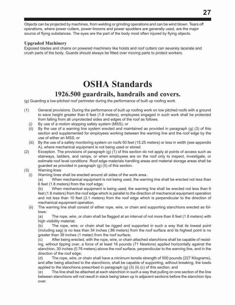
(g) Guarding a low-pitched roof perimeter during the performance of built up roofing work.
(1) General provisions. During the performance of built up roofing work on low pitched roofs with a groundto eave height greater than 6 feet (1.8 meters), employees engaged in such work shall be protectedfrom falling from all unprotected sides and edges of the roof as follows.
(i) By use of a motion stopping safety system (MSS); or(ii) By the use of a warning line system erected and maintained as provided in paragraph (g) (3) of this
section and supplemented for employees working between the warning line and the roof edge by theuse of either an MSS; or
(iii) By the use of a safety monitoring system on roofs 50 feet (15.25 meters) or less in width (see appendixA), where mechanical equipment is not being used or stored.
(2) Exception. The provisions of paragraph (g) (1) of this section do not apply at points of access such asstairways, ladders, and ramps, or when employees are on the roof only to inspect, investigate, orestimate roof level conditions. Roof edge materials handling areas and material storage areas shall beguarded as provided in paragraph (g) (5) of this section.
(3) Warning lines(i) Warning lines shall be erected around all sides of the work area..
(a) When mechanical equipment is not being used, the warning line shall be erected not less than6 feet (1.8 meters) from the roof edge;(b) When mechanical equipment is being used, the warning line shall be erected not less than 6feet (1.8 meters) from the roof edge which is parallel to the direction of mechanical equipment operationand not less than 10 feet (3.1 meters) from the roof edge which is perpendicular to the direction ofmechanical equipment operation.
(ii) The warning line shall consist of either rope, wire, or chain and supporting stanchions erected as fol-lows:(a) The rope, wire, or chain shall be flagged at an interval of not more than 6 feet (1.8 meters) withhigh visibility material;(b) The rope, wire, or chain shall be rigged and supported in such a way that its lowest point(including sag) is no less than 34 inches (.86 meters) from the roof surface and its highest point is nogreater than 39 inches (1 meter) from the roof surface;(c) After being erected, with the rope, wire, or chain attached stanchions shall be capable of resist-ing, without tipping over, a force of at least 16 pounds (71 Newtons) applied horizontally against thestanchion, 30 inches (0.76 meters) above the roof surface, perpendicular to the warning line, and in thedirection of the roof edge;(d) The rope, wire, or chain shall have a minimum tensile strength of 500 pounds (227 Kilograms),and after being attached to the stanchions, shall be capable of supporting, without breaking, the loadsapplied to the stanchions prescribed in paragraph (g) (3) (ii) (c) of this section; and(e) The line shall be attached at each stanchion in such a way that pulling on one section of the linebetween stanchions will not result in slack being taken up in adjacent sections before the stanchion tipsover.
28(iii) Access paths shall be erected as follows:
(a) Points of access, materials handling areas and material storage areas shall be connected to thework area by a clear access path formed by 2 warning lines;(b) When a path to a point of access is not in use, a rope, wire, or chain equal in strength and heightto the warning line shall be placed across the path at the point where the path intersects the warning lineerected around the work area.
(4) Mechanical Equipment. Mechanical equipment may be used or stored only in areas where employeesare being protected by either a warning line or an MSS. Mechanical Equipment may not be used orstored between the warning line and the roof edge unless the employees are being protected by a MSS.Mechanical equipment may not be used or stored where the only protection provided is by a safetymonitoring system.
(5) Roof Edge Materials Handling Areas and Materials Storage. Employees working in a roof edge materi-als handling or materials storage area located on a low pitch roof with a ground to eave height of greaterthan 6 feet (1.8 meters) shall be protected from falling by the use of an MSS along all unprotected roofsides and edges of the area.
(i) When guardrails are used at hoisting areas, a minimum of four feet of guardrail shall be erected on eachside of the access point through which materials are hoisted.
(ii) A chain or gate shall be placed across the opening between the guardrail sections when hoisting opera-tions are not taking place.
(iii) When guardrails are used at bitumen pipe outlets, a minimum of four feet of guardrail shall be erected oneach side of the pipe.
(iv) When safety belt systems are used, they shall not be attached to the hoist.(v) When safety belt systems are used they shall be rigged to allow the movement of employees only as far
as the roof edge.(vi) Materials may not be stored within 6 feet (1.8 meters) of the roof edge unless guardrails are erected at
the roof edge.(vii) Materials that are piled, grouped, or stacked shall be stable and self supporting.
(6) Training(i) The employer shall provide a training program for all employees engaged in build up roofing work so that
they are able to recognize and deal with the hazards of falling associated with working near a roofperimeter. The employees shall also be trained in the safety procedures to be followed in order toprevent such falls.
(ii) The employer shall assure that employees engaged in build up roofing work have been trained andinstructed in the following areas:(a) The nature of fall hazards in the work area near a roof edge;(b) The function, use, and operation of the MSS, warning line, and safety monitoring systems to beused.(c) The correct procedures for erecting, maintaining, and disassembling the systems to be used;(d) The role of each employee in the safety monitoring system when it is in use.(e) The limitations on the use of mechanical equipment; and(f) The correct procedures for the handling and storage of equipment and materials.
(iii) Training shall be provided for each newly hired employee and for all other employees as necessary toassure that employees maintain proficiency in the areas listed in paragraph (g) (6) (ii) of this section.
Section 1926.502 of 29 CFR Part 1926 Is Amended By Adding a New Paragraph (p) to Read asFollows:(p) For the purpose of paragraph (g) of 1936.500, the following definitions shall apply:
(1) “Built-up-roofing” – a weatherproof cover, applied over roof decks, consisting of either liquid appliedsystem, on single-ply system or a multiple-ply system. Liquid apply systems generally consist of siliconrubber, plastics, or similar material applied by spray or roller equipment. Single-ply systems generallyconsist of a single layer of synthetic rubber, plastic, or similar material, and a layer of adhesive. Multiple-ply systems generally consist of a layer of felt and bitumen, and may be covered by a layer of mineralaggregate.
(2) “Built-up-roofing work” – the hoisting, storage, application, and removal of built-up-roofing materials andequipment, including related insulation, sheet metal, and vapor barrier work but not including the con-struction of the roof deck.
29(3) “Low pitched roof” – a roof having a slope less than or equal to four in twelve.(4) “Mechanical equipment” – all motor or human propelled wheeled equipment except wheel borrows and
mop carts.(5) “MSS” (motion stopping safety system) – fall protection using the following equipment singly or in com-
bination; standard railings (guardrails) as described in 1926.500(f); scaffolds or platforms with guardrailsas described in section 1926.451; safety nets as described in 1926.105; and safety belt systems asdescribed in 1926.104.
(6) “Roof” – the exterior surface on the top of the building. This does not include floors, which because thebuilding has not been completely built, temporarily becomes the top surface of the building.
(7) “Safety monitoring system” – a safety system in which a competent person monitors the safety of allemployees in a roofing crew, and warns them when it appears to the monitor that they are unaware ofthe hazard or are acting in unsafe manner. The competent person must be on the same roof and withinvisual sighting distance of the employees, and must be close enough to verbally communicate with theemployees.
(8) “Unprotected side or edge” – any side or edge of a roof perimeter where there is no wall 3 feet (.9meters) or more in height.
(9) “Work area” – that portion of a roof where built-up roofing work is being performed.

30
Notes:
31
CUT ALLONG DOTTED LINES AND MAIL TO GARLOCK EQUIPMENT CO., 2601 NIAGARA LN., MINNEAPOLIS, MN 55447

32

33
Notes:

34
Notes:
35
2601 NIAGARA LANEPLYMOUTH, MN 55447
Mail to:Company
Street
City, State, Zip
Your Name
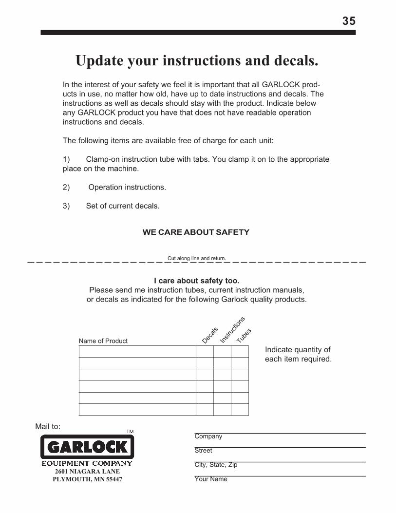
I care about safety too.Please send me instruction tubes, current instruction manuals,
or decals as indicated for the following Garlock quality products.
Tube
s
Instru
ction
s
Decals
Name of ProductIndicate quantity ofeach item required.
WE CARE ABOUT SAFETY
Cut along line and return.
Update your instructions and decals.In the interest of your safety we feel it is important that all GARLOCK prod-ucts in use, no matter how old, have up to date instructions and decals. Theinstructions as well as decals should stay with the product. Indicate belowany GARLOCK product you have that does not have readable operationinstructions and decals.
The following items are available free of charge for each unit:
1) Clamp-on instruction tube with tabs. You clamp it on to the appropriateplace on the machine.
2) Operation instructions.
3) Set of current decals.

2601 NIAGARA LANE, PLYMOUTH, MN 55447Phone: (763) 553-1935
Fax (763) 553-7765