Embed Size (px)
Citation preview
Vysoká škola báňská – Technická univerzita Ostrava
NANOMATERIALS II. Selected chapters
Miroslav Greger
Ostrava 2015
Nanomaterials II.
© Miroslav Greger 2
CONTENT
1. PREFACE: SPD – NANOMATERIALS AND NANOTECHNOLOGY 3
2. PROPERTIES OF FINE GRAINED AND NANOSTRUCTURED MATERIALS 4 2.1 Mechanical properties of fine grained materials 4
2.1.1 Modulus of elasticity in tension 5 2.1.2 Yield strength, hardness, strength 5 2.1.3 Hall-Petch relation 5 2.1.4 Diffusion creep 6 2.1.5 Grain boundary sliding 6 2.1.6 Yield strength at very small grains 7
3. PLASTIC PROPERTIES OF ULTRA-FINE GRAINED AND NANOSTRUCTURED MATERIALS 8 3.1 Ductility, plasticity 8 3.2 Superplasticity 9
4. GRAIN GROWTH AND TEMPERATURE STABILITY OF ULTRA-FINE GRAINED AND NANOSTRUCTURED MATERIALS 11 4.1 Grain growth 11 4.2 Temperature stability 11
5. METHODS OF PREPARATION OF ULTRA-FINE GRAINED MATERIALS 13 5.1 Batch processing 14
5.1.1 ECAP – Equal Channel Angular Pressing 14 5.1.2 HPT – High Pressure Torsion 15 5.1.3 HPTT - High-Pressure Tube Twisting 16 5.1.4 RCS – Repetitive Corrugation Straightening 16 5.1.5 TE - Twist Extrusion 16
6. CONTINUOUS METHODS OF PREPARATION OF ULTRA-FINE GRAINED MATERIALS 18 6.1 Continuous processes 18
6.1.1 ARB – Accumulative Roll Bonding 18 6.1.2 Conshearing Process 18 6.1.3 C2S2 - Continuous Confined Strip Shearing 19 6.1.4 ECAP – Conform 19 6.1.5 Continuous RCS (Repetitive Corrugation and Straightening) 19
6.2 Comparison of the severe plastic deformation methods 20 6.3 Research of steels with ultra-fine grained and nanocrystalline structure 21 6.4 The most important research workplaces 21
7. CONCLUSION 23
LITERATURE 24
Nanomaterials II.
© Miroslav Greger 3
1. PREFACE: SPD – NANOMATERIALS AND NANOTECHNOLOGY
In recent 20 years the attention was focused on the research of nanostructured materials, which promise to achieve new mechanical and other physical properties in comparison with their coarse-grained equivalents.
There are various shapes and forms of nanostructured materials featuring extraordinary chemical, physi-cal and mechanical properties. If the grain size is in the critical size region, i.e. 10 ÷ 20 nm, then 50 vol.% of atoms are connected with grain boundaries or interphase interface. On the basis of this fact the grain bounda-ry regions influence the complex properties of nanomaterials. In this case dislocation chains do not originate and the Hall-Petch relation for formation of coarse-grained material is not applied. Nevertheless, grain boundaries play an important part for deformation of nanomaterials, the most frequently superelasticity oc-curs here at lower temperatures than in conventional materials.
Structures of nanocrystalline materials can be divided into four groups: dimensionless atomic clusters, one-dimensional modulated layers, two-dimensional fine-grained layers, three-dimensional nanostructures.
Nanocrystalline materials can comprise crystals, quasicrystals and amorphous phases, which may occur in metals, intermetallics, ceramics and composites. Gleiter divided nanocrystalline matters into twelve groups relating to their shape and chemical composition of basic structural elements. The first dividing of nano-materials relates to shapes of crystallites: layered crystals, rod crystals (the thickness of which is in order-of-magnitude of several nanometers) and equilateral crystals.
The second dividing categorizes the above mentioned three groups into four subgroups according to the difference in chemical composition of crystals. The atomic structure of all crystals is identical. A single dif-ference between them is their crystallographic orientation. However, this does not apply in regions of bound-aries, where crystals meet. In the regions of crystal boundaries the average atom density and ordering be-tween the nearest neighbours of atoms differ. The presence of two structural components of a comparable volume with a typical crystal size of several nanometers is decisive for properties of nanostructural materials.
An important group of nanomaterials are nanocomposite layers, the thickness of which is lower than 100 nm. Many times the layers consist of a two-phase structure and are formed as a result of segregation of the second phase on the boundaries of the first phase. The essential property of these layers is that the number of atoms in the boundary regions is comparable to or higher than the number of atoms in the volume, which are surrounded by the segregated atoms. This means that the material properties are not determined only and solely by atoms in grains, as in polycrystalline metals, but also by behavior of boundary atoms and their mu-tual interaction. This fact dramatically differs properties of highly fine-grained layers from properties of pol-ycrystalline layers consisting of large grains (> 100 nm).
Nanocrystalline materials are perspective materials with many unique properties. Their greatest asset is a possibility to enhance usable properties substantially in comparison with conventional “coarse-grained” ma-terials. Some ceramic and metal nanocrystalline materials have been used in operation already. While the material grain sizes decrease, the grain surface sizes increase, which in a case of metal materials leads to enhancement of strength and hardness, electrical resistance, an increase in the specific thermal capacity, a decrease in the thermal conductivity and enhancement of magnetic properties. Nanocrystalline metal materi-als can also be applied as catalyzers with an active area many-fold higher in comparison with coarse-grained materials.
In preparation of nanocrystalline metal structural materials, the preparation of bulk nanostructured mate-rials has been and still is a problem. Over time, various methods for the preparation of these materials have been developed, whereas the main problem, which is being solved now, is the inner homogeneity of semi-products (in the preparation technologies based on compaction of powder nanomaterials), a size of the ob-tained nanostructured materials (in technologies using grain refinement by severe plastic deformations) and also plastic properties of materials manufactured this way. Another remaining problem is enhancement of resistance of fine-grained materials against grain growth during its processing at higher temperatures or heat-ing, which is many times necessary for performing the forming process and for achieving required proper-ties.
Usually, nanostructured materials are considered those the structure of which consists of components hav-ing at least one dimension between 1 ÷ 100 nm. These components may be atom clusters (to c. 10 nm), larger particles (10 ÷ 100 nm), subgrains, grains, lamellae, layers, filaments, tubes, etc. For instance, lamellar pearl-ite can be considered a nanocomposite (it consists of ferrite and cementite lamellae of widths usually below 100 nm).
Nanomaterials II.
© Miroslav Greger 4
Many authors use a term ‘nanostructured material’ for the materials comprising particles of sizes below 1 micrometer. For materials with components ranging between 100 ÷ 1000 nm, the name ultra-fine grained materials is also used.
The research of preparation of ultra-fine grained and nanostructured materials and investigation of their properties and possibilities of their practical application has been focused on a large quantity of chemical elements, particularly metals, their alloys, but also e.g. on semiconductors. From the point of view of practi-cal operation, the highest attention is nowadays focused on aluminum, copper and titanium alloys and a number of intermetallic compounds. The research of preparation technologies and properties of ultra-fine grained structured steels is essential, too.
These lecture notes are a follow-up to the part Nanomaterials I and deal particularly with preparation of ultra-fine grained materials through the extreme plastic deformation methods known under the abbrevia-tion SPD (Severe Plastic Deformation). This is the topic the main attention is focused on in these lecture notes. 2. PROPERTIES OF FINE GRAINED AND NANOSTRUCTURED
MATERIALS
Time needed for studying: 90 minutes
Aim: After studying this chapter you will
Define ultra-fine grained and nanostructured materials Describe the dependency of mechanical properties of nanostructured materials on a grain size Calculate strength properties of nanostructured materials using the Hall-Petch relation
Explication
2.1 Mechanical properties of fine grained materials
It has been known that strength and hardness of a material increase, while a grain size in its structure de-creases, which has been known since the beginning of the fifties of the last century, when N.J. Petch and E.O. Hall independently of each other defined the well-known Hall-Petch relation:
σy = σo + k d-1/2 , (1)
where σy stands for yield strength, σo stands for a certain stress required to overcome Peierls-Nabarro friction stress, resistance of dissolved foreign atoms, resistance of precipitates form the solid solution and defects of a lattice, k stands for a constant and it is a factor for the shear stress required to release accumulated disloca-tions and d stands for a grain dimension.
Equation (1) implies that the material yield strength increases, while the grain dimensions decrease. This applies also for hardness of a polycrystalline material. This phenomenon became a driving force for the re-search and development of high strength structural materials, especially in steels. Later it was shown that refinement may lead also to the increased ductility of metallic materials.
A preparation of sufficiently large samples with small dimensions of structural components was the main problem for investigation of strength properties in particular. Attention to this topic was turned in the early eighties of the last century especially by Gleiter et al., who started to deal with preparation and properties of materials with ultra-fine grained structure, which were called nanocrystalline materialsi by them. Plain enough was a consideration that based on the same hardening mechanism, reducing the grain sizes down to the nanometer level may result in a great increase in the material strength. It can be calculated that for grain sizes of 10 ÷ 20 nm the yield strength value gets close to the theoretical strength of the material. Over time
Nanomaterials II.
© Miroslav Greger 5
the validity of relation (1) has proved, with the exception of its validity for large grains and very fine grains (c. below 10 nm).
Step by step, the results of the original investigation of ultra-fine grained materials were revised, since the results were not reliable due to faulty preparation of the samples. At those times the materials were pre-pared from nanoparticles (nanocrystals) by imperfect compacting processes (sintering etc.), leading in the early stages of the research to structures containing many pores and other defects (e.g. cracks), which distort-ed the results.
Nanocrystalline materials contain high density of grain boundaries and other interfaces, which has led to an idea of a possibility to extend the effect of high-temperature deformation mechanisms respecting the role of grain boundaries to lower temperature regions. For example, there was an idea that a nanocrystalline ma-terial would be deformable by processes controlled by the grain boundary diffusion at significantly lower homologous temperatures. This indicated a possibility of production of plastic ceramics, effect of diffusion creep of pure copper at room temperature, a possibility of superplastic behavior of metals and ceramics at low temperatures etc.
In the following part the most important mechanical properties of materials with ultra-fine grained and nanocrystalline structures and mechanisms of processes that determine them are discussed. 2.1.1 Modulus of elasticity in tension
Although former works pointed out low values of the elasticity modulus of nanocrystalline materials compared to coarse-grained materials, it has been judged nowadays that modulus of elasticity in tension E is the same for polycrystalline as well as for nanocrystalline materials. 2.1.2 Yield strength, hardness, strength
The basis of every deformation behavior is kinetics of generation of defects (lattice defects, on interphas-es), their motion and annihilation. Micro-mechanisms respecting lattice dislocations, dislocations on grain boundaries and vacancies are particularly important. These defects may contribute to the total plasticity, independently or in a combination, but a dominating mechanism can be identified by evaluation of strain rate, grain size and temperature dependence.
Above all, three ideas of the mechanical behavior of nanocrystalline materials have attracted the attention: 1. The Hall-Petch relation, in which the deformation stress dependency on the grain size at low tempera-
tures results from the process of blocking the move of dislocations on grain boundaries. 2. Diffusion creep mechanism which involves the movement of vacancies at the gradient of the applied
stress. 3. The mechanism of grain boundary sliding, which involves a movement of all three above mentioned
defects depending on specific micro-mechanisms.
2.1.3 Hall-Petch relation
In the above mentioned Hall-Petch relation (1), σo changes along with chemical composition of material, structure and technological processing. k constant is thermally independent, but σo increases noticeably, while temperature decreases.
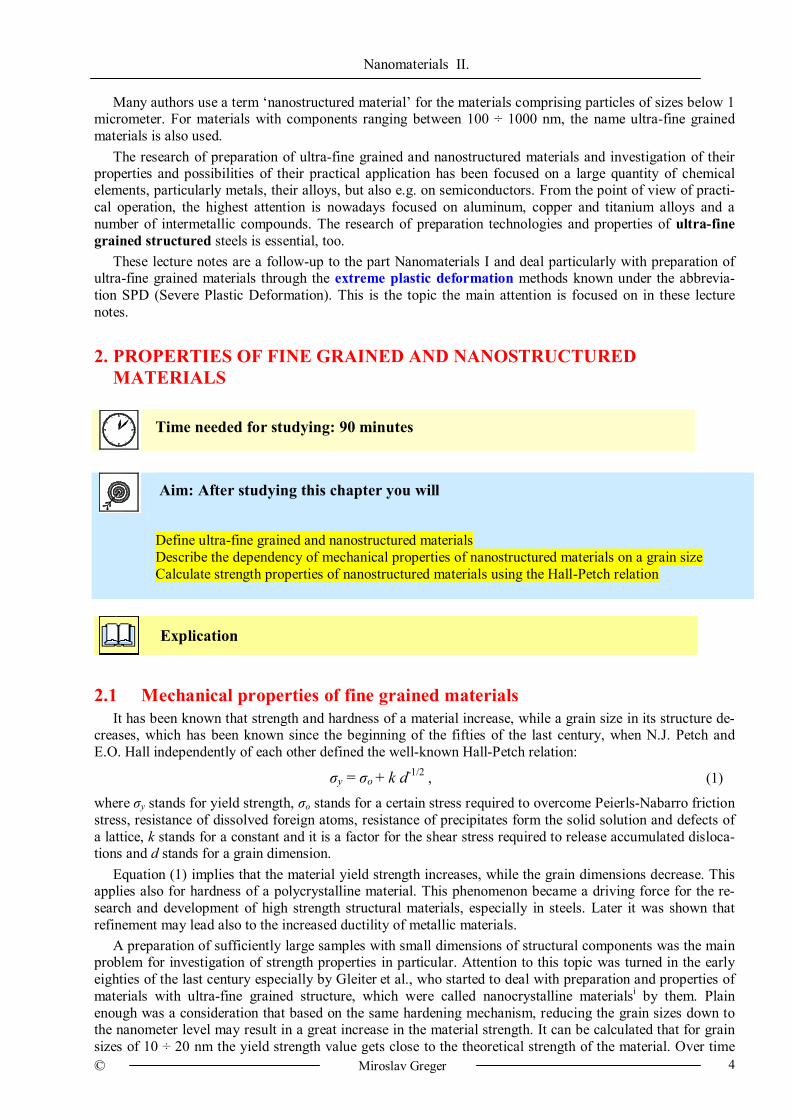
Lots of mechanisms were suggested for explanation of the Hall-Petch relation, three of which are sche-matically depicted in Fig. 1.
Dislocation pile-up before the grain boundary, which at a specific stress activate the Frank-Read source in a neighbouring grain and deformation propagates through the grain and through the entire material after-wards.
Generation of dislocations on ledges of grain boundaries formed during the deformation. Generation of dislocations on grain boundaries forming a hardening layer on them. In this case equation (1) includes also the expression d–1, which is significant at small grain sizes and reduces a value of k constant.
Other mechanisms were proposed by Conrad, Ashby and others; they are based on activity of dislocations in grains or near their boundaries.
Nanomaterials II.
© Miroslav Greger 6
Fig. 1 Basic models proposed to explain the Hall-Petch relation
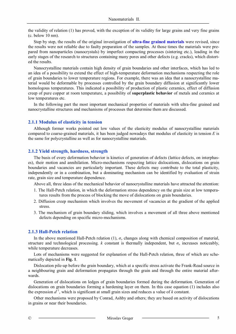
It was found out that the Hall-Petch relation (1) applies for various materials approximately to the grain
dimension of 30 nm, then the strength stops to increase or even decreases. This is schematically depicted in Fig. 2. A region below the critical grain size dc (regime II - G.B. sliding) is sometimes called the inverse Hall-Petch relation and dislocation mechanisms stop to have effect here.
Fig. 2 Hardness (strength) to the grain size dependency in nanometer field
2.1.4 Diffusion creep
Coble has proposed a modification of the known Nabarro-Herring diffusion creep mechanism, involving into their relation the faster grain boundary diffusion at medium temperatures. He presented the relation
έ = 47.7 (Ω δ Dg σ/k T d3), (2) where έ stands for the strain rate, Ω stands for the atomic volume, δ stands for the grain boundary thickness, Dg stands for the grain boundary diffusivity, σ stands for the strain stress, k stands for the Boltzmann con-stant, T stands for the absolute temperature and d stands for the grain size.
The grain boundary thickness value is typically 1 nm. According to relation (2), if the grain size decreases from 10 μm to 10 nm (i.e. by three orders of magnitude), the strain rate at creep will increase by nine orders of magnitude. At the same time, it is known that the grain boundary diffusivity in nanocrystalline materials is higher than in materials with larger grains. A combination of these phenomena has led to the expectation of a possibility of plastic deformation of ceramic materials and intermetallic compounds at room temperature. The theory of Coble creep effect in a region below dc was supported e.g. by Masumura et al. In his model the dependency of the H-P relation should be sensitive to temperature, which has not been observed so far. 2.1.5 Grain boundary sliding
A constitutive relation for grain boundary sliding can be written as: έ = 2.105 (Dg G b/k T) (b/d)3 (σ/G)2 (3)
where G stands for shear modulus, b stands for the Burgers vector, the other symbols have the same meaning as in relation (2).
The grain boundary sliding is a dominating deformation mechanism of the structural superplasticity of fi-ne-grained materials. A prerequisite for the relation (3) validity for nanocrystalline materials is the grain boundary sliding micro-mechanism effect in this dimension area.
Nanomaterials II.
© Miroslav Greger 7
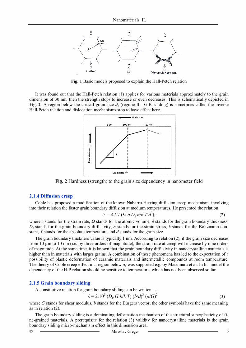
The validity of relations (2) and (3) was tested experimentally. Fig. 3 shows the dependencies of the strain stress on the strain rate according to relation (2) – a dashed line and relation (3) – a dotted line for 673 K temperature. Both the relations are compared with the results of tests of pure iron with grain dimensions of 100 nm, made by severe plastic deformation, without pores and cracks that can be found in samples manu-factured by powder metallurgy. A high discordance between the experimental results and theoretical assump-tions can be seen. The measured values of the strain stress are much higher. The diffusion creep model will need to be made more accurate then.
Fig. 3 Comparison of experimentally found values of strain stress with a theoretical prediction according to relations (2) and (3) for nanocrystalline iron with grain dimensions of 100 nm
2.1.6 Yield strength at very small grains Unsuitability of the Hall-Petch relation (1) for a calculation of yield strength of nanocrystalline materials
(see Fig. 2) at the grain size values below c. 30 nm and the evident inapplicability of relations (2) and (3) led to an attempt to explain this phenomenon. This co-called inverse Hall-Petch relation was observed in many materials and a relationship is assumed.
dky /1 . (4)
To explain the limited validity of the Hall-Petch relation, the following models are used: An influence of the volume occupied by triple points. As the grain dimension decreases to nanometers,
the volume proportion of the triple point area, to which softening of material may be ascribed, becomes more significant. This idea was for the first time presented by V.B. Rjabuchin and supported experimentally e.g. by Palumbo et al. on samples of nanocrystalline Ni obtained by electro-deposition.
A composite model. This model takes into account both the influence of the crystal matrix and the inter-crystalline layers. Grjaznov et al. formulated a dependency of yield strength on the grain size of nanocrystal-line materials as a sum of a contribution of a matrix and an intercrystalline contribution. Both of the contri-butions are connected linearly with the corresponding shear moduli and they are the grain size function. This model seems not to be adequately theoretically supported.
Conclusion While the material grain size decreases, its strength (hardness, yield strength) increases as high as to the nanocrystalline material region. The Hall-Petch relation describes this phenomenon well enough (1). This fact is a driving force for the research of manufacturing technologies of massive nanocrystalline materials for structural purposes. In the grain critical size area dc (below c. 50 ÷ 30 nm) the dislocation activity diminishes and yield strength (very high) becomes independent of the grain size, or even decreases in some materials.
Strain rate (s–1)
Stre
ss (M
Pa)
10–5 10–4 10–3 10–2
105
104
103
102
101
Nanocrystalline Fe, 673 K, 100 nm
Experimental values Diffusion creep (Coble) Grain boundary sliding (Sherry and Wadsworth)
Nanomaterials II.
© Miroslav Greger 8
3. PLASTIC PROPERTIES OF ULTRA-FINE GRAINED AND NANOSTRUCTURED MATERIALS
Time needed for studying: 90 minutes
Aim: After studying this chapter you will:
Define plastic properties of ultra-fine grained and nanostructured materials Calculate the basic plastic properties Determine an influence of strain rate, homologous temperature and grain size on the superplastic behavior of metal materials
Explication
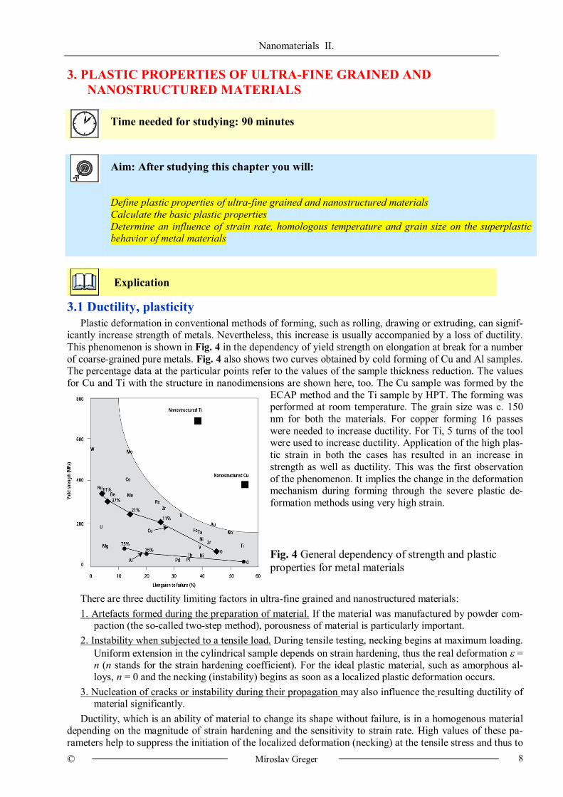
3.1 Ductility, plasticity Plastic deformation in conventional methods of forming, such as rolling, drawing or extruding, can signif-
icantly increase strength of metals. Nevertheless, this increase is usually accompanied by a loss of ductility. This phenomenon is shown in Fig. 4 in the dependency of yield strength on elongation at break for a number of coarse-grained pure metals. Fig. 4 also shows two curves obtained by cold forming of Cu and Al samples. The percentage data at the particular points refer to the values of the sample thickness reduction. The values for Cu and Ti with the structure in nanodimensions are shown here, too. The Cu sample was formed by the
ECAP method and the Ti sample by HPT. The forming was performed at room temperature. The grain size was c. 150 nm for both the materials. For copper forming 16 passes were needed to increase ductility. For Ti, 5 turns of the tool were used to increase ductility. Application of the high plas-tic strain in both the cases has resulted in an increase in strength as well as ductility. This was the first observation of the phenomenon. It implies the change in the deformation mechanism during forming through the severe plastic de-formation methods using very high strain.
Fig. 4 General dependency of strength and plastic properties for metal materials
There are three ductility limiting factors in ultra-fine grained and nanostructured materials: 1. Artefacts formed during the preparation of material. If the material was manufactured by powder com-
paction (the so-called two-step method), porousness of material is particularly important. 2. Instability when subjected to a tensile load. During tensile testing, necking begins at maximum loading.
Uniform extension in the cylindrical sample depends on strain hardening, thus the real deformation = n (n stands for the strain hardening coefficient). For the ideal plastic material, such as amorphous al-loys, n = 0 and the necking (instability) begins as soon as a localized plastic deformation occurs.
3. Nucleation of cracks or instability during their propagation may also influence the resulting ductility of material significantly.
Ductility, which is an ability of material to change its shape without failure, is in a homogenous material depending on the magnitude of strain hardening and the sensitivity to strain rate. High values of these pa-rameters help to suppress the initiation of the localized deformation (necking) at the tensile stress and thus to
Nanomaterials II.
© Miroslav Greger 9
increase ductility. The strain hardening results from the accumulation of crystal lattice defects, such as dislo-cations, which makes further deformation more difficult. However, in nanostructured metals the accumula-tion of dislocations is impossible, since grains are too smallii. Dislocations are emitted from one grain bound-ary segment and vanish in another, thus the inside of the grains is dislocationless. In many nanostructured metals a zero strain hardening has been really observed. Nevertheless, a distinctive relationship between a certain mechanism of plastic deformation and ductility has not been investigated yet. The endeavor to en-hance low values of nanocrystalline materials ductility is a subject of continuing research, the results have been optimistic so far.
3.2 Superplasticity The superplasticity phenomenon was observed in many fine-grained crystalline materials. For this phe-
nomenon to occur, two essential conditions must be met: 1. The material grain size must be very small (typically below 10 μm) and grain boundaries must be
large-angled. 2. Deformation in tension must be applied at relatively high temperatures, so that diffusion-controlled
mechanisms can occur. This is usually at temperatures above 0.5 Tm. During superplastic deformation, grains preserve an equiaxed shape in principle, even if elongated very
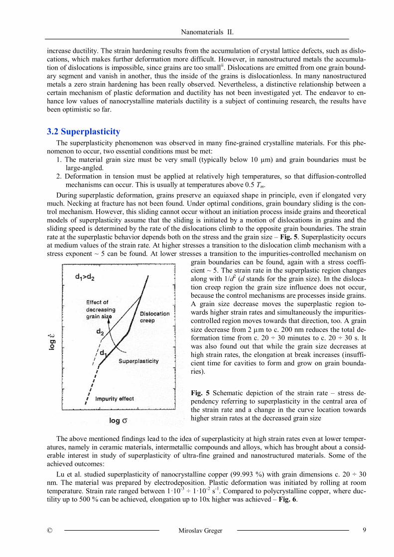
much. Necking at fracture has not been found. Under optimal conditions, grain boundary sliding is the con-trol mechanism. However, this sliding cannot occur without an initiation process inside grains and theoretical models of superplasticity assume that the sliding is initiated by a motion of dislocations in grains and the sliding speed is determined by the rate of the dislocations climb to the opposite grain boundaries. The strain rate at the superplastic behavior depends both on the stress and the grain size – Fig. 5. Superplasticity occurs at medium values of the strain rate. At higher stresses a transition to the dislocation climb mechanism with a stress exponent ~ 5 can be found. At lower stresses a transition to the impurities-controlled mechanism on
grain boundaries can be found, again with a stress coeffi-cient ~ 5. The strain rate in the superplastic region changes along with 1/d2 (d stands for the grain size). In the disloca-tion creep region the grain size influence does not occur, because the control mechanisms are processes inside grains. A grain size decrease moves the superplastic region to-wards higher strain rates and simultaneously the impurities-controlled region moves towards that direction, too. A grain size decrease from 2 m to c. 200 nm reduces the total de-formation time from c. 20 ÷ 30 minutes to c. 20 ÷ 30 s. It was also found out that while the grain size decreases at high strain rates, the elongation at break increases (insuffi-cient time for cavities to form and grow on grain bounda-ries). Fig. 5 Schematic depiction of the strain rate – stress de-pendency referring to superplasticity in the central area of the strain rate and a change in the curve location towards higher strain rates at the decreased grain size
The above mentioned findings lead to the idea of superplasticity at high strain rates even at lower temper-atures, namely in ceramic materials, intermetallic compounds and alloys, which has brought about a consid-erable interest in study of superplasticity of ultra-fine grained and nanostructured materials. Some of the achieved outcomes:
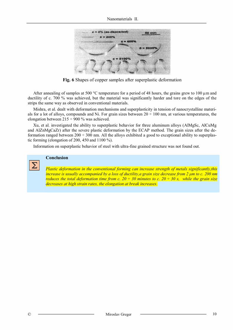
Lu et al. studied superplasticity of nanocrystalline copper (99.993 %) with grain dimensions c. 20 ÷ 30 nm. The material was prepared by electrodeposition. Plastic deformation was initiated by rolling at room temperature. Strain rate ranged between 1·10-3 ÷ 1·10-2 s-1. Compared to polycrystalline copper, where duc-tility up to 500 % can be achieved, elongation up to 10x higher was achieved – Fig. 6.
Nanomaterials II.
© Miroslav Greger 10
Fig. 6 Shapes of copper samples after superplastic deformation
After annealing of samples at 500 °C temperature for a period of 48 hours, the grains grew to 100 m and
ductility of c. 700 % was achieved, but the material was significantly harder and tore on the edges of the strips the same way as observed in conventional materials.
Mishra, et al. dealt with deformation mechanisms and superplasticity in tension of nanocrystalline materi-als for a lot of alloys, compounds and Ni. For grain sizes between 20 ÷ 100 nm, at various temperatures, the elongation between 215 ÷ 900 % was achieved.
Xu, et al. investigated the ability to superplastic behavior for three aluminum alloys (AlMgSc, AlCuMg and AlZnMgCaZr) after the severe plastic deformation by the ECAP method. The grain sizes after the de-formation ranged between 200 ÷ 300 nm. All the alloys exhibited a good to exceptional ability to superplas-tic forming (elongation of 200, 450 and 1100 %).
Information on superplastic behavior of steel with ultra-fine grained structure was not found out.
Conclusion Plastic deformation in the conventional forming can increase strength of metals significantly,this increase is usually accompanied by a loss of ductility,a grain size decrease from 2 μm to c. 200 nm reduces the total deformation time from c. 20 ÷ 30 minutes to c. 20 ÷ 30 s, while the grain size decreases at high strain rates, the elongation at break increases.
Nanomaterials II.
© Miroslav Greger 11
4. GRAIN GROWTH AND TEMPERATURE STABILITY OF ULTRA-FINE GRAINED AND NANOSTRUCTURED MATERIALS
Time needed for studying: 90 minutes
Aim: After studying this chapter you will: Describe the grain growth in conventional and nanocrystalline materials Define the activation energy for the grain growth in nanocrystalline materials Describe the grain growth kinetics and mechanism Determine the phases preventing or decelerating migration of grain boundaries
Explication
4.1 Grain growth Regarding to small grain dimensions and ensuing large surface area, nanocrystalline materials tend to the
grain growth. Knowledge of thermal stability of nanocrystalline materials is important both for scientific and technological reasons. From the technological point of view, the thermal stability is important for e.g. na-nopowders consolidation with elimination of structure coarsening or for superplastic processing of ceramics and metals. From the scientific point of view, it is important whether the grain growth mechanism in nano-crystalline materials differs from the grain growth in coarse-grained materials.
The grain growth in conventional materials is described by the equation
dn – don = Ko exp (-Q/R T) t , (4)
where d stands for the grain size after annealing the sample at temperature T for a period t, do stands for the initial grain size, n stands for the grain growth exponent, Ko stands for the constant, Q stands for the activa-tion energy of the grain growth and R stands for the gas constant. Q and n are important parameters charac-terizing the grain growth kinetics and mechanism. The exponent n in an ideal case equals 2, which assumes a parabolic course of the grain growth.
However, in nanocrystalline materials the exponent n values from 2 to 10 were observed. The value 2 is only reached when annealing is performed at relatively high values of the temperature proportion T/Tm (Tm is melting point of the investigated material). Factors, which could explain higher values of the exponent n, include segregation of dissolved substances on grain boundaries and grain boundary blocking. The activation energy for the grain growth in nanocrystalline materials (Qn) is usually compared to the activation energy of volume diffusion (Qv) or grain boundary diffusion (Qgb) in coarse-grained materials. Usually Qn can be com-pared to Qgb rather than to Qv, although some exceptions were found. It was also observed that Qn value of nanocrystalline Fe at temperatures above 500 °C got close to Qv for coarse-grained Fe and at temperatures below 500 °C got nearer to Qgb, which indicates different mechanisms of the grain growth. A large grain growth was observed e.g. in annealing nanocrystalline materials prepared by high plastic strain or prepared by condensation of clusters and their consolidation.
4.2 Temperature stability In order to use the advantageous properties of a nanostructure is important to maintain the dimensions of
nanocrystals during heat treatment, forming, in case of need during processing at higher temperatures, the same or only a little increased. One of the methods to achieve this is to locate a fine dispersed phase on the grain boundary to avoid or moderate their migration. This strategy was used e.g. by Kim et al. for develop-ment of a composite ceramic material, which sustained high strain rates during superplastic forming. The material was a nanocomposite containing ZnO, alumino-magnesium spinel and α-Al2O3. The nanocomposite
Nanomaterials II.
© Miroslav Greger 12
was superplastic even at strain rate 1 s-1. Ductility exceeding 1000 % was achieved. Another method is a segregation of impurities on grain boundaries and achieving the “grain boundary stabilized structure”. An example of this method can be found in the work by Liu et al with fine-grained RuAl containing impurities. Another method to prevent the grain growth is also residual porosity, which was observed in nanocrystalline ceramics and nanocrystalline Pd prepared by electrodeposition.
Conclusion Nanocrystal size increases during forming and processing at higher temperatures, the grain growth in conventional materials is described by equation (4), the grain growth depends on temperature T, exposure time t, grain growth exponent n, constant Ko and the activation energy of the grain growth Q, exponent n for conventional materials (coarse-grained) is about the value 2, for nanostructured and ultra-fine grained materials, n ranges between 2 ÷ 10.
Nanomaterials II.
© Miroslav Greger 13
5. METHODS OF PREPARATION OF ULTRA-FINE GRAINED MATERIALS
Time needed for studying: 90 minutes
Aim: After studying this chapter you will: Define the basic methods of preparation of ultra-fine grained and nanostructured materials. Describe the preparation of nanostructured and ultra-fine grained materials by the SPD processes. Select an applicable method of preparation of an ultra-fine grained structure through application of ECAP. Calculate a value of shear and real strain in the particular SPD technologies.
Explication
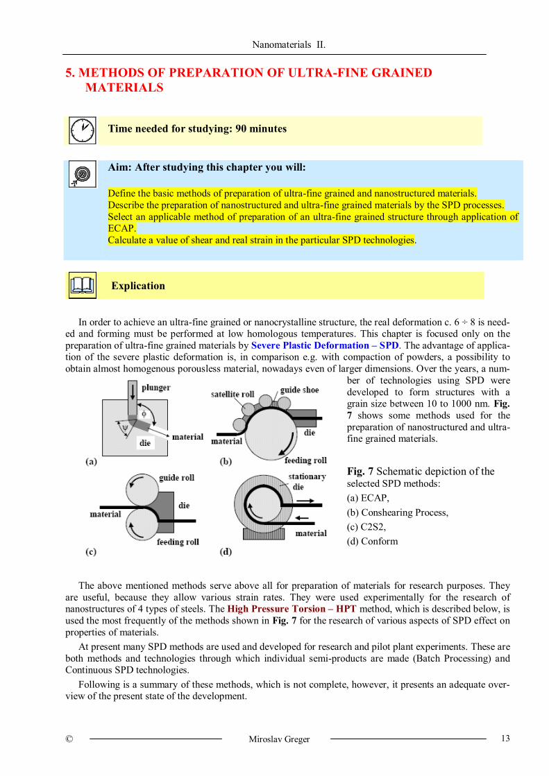
In order to achieve an ultra-fine grained or nanocrystalline structure, the real deformation c. 6 ÷ 8 is need-
ed and forming must be performed at low homologous temperatures. This chapter is focused only on the preparation of ultra-fine grained materials by Severe Plastic Deformation – SPD. The advantage of applica-tion of the severe plastic deformation is, in comparison e.g. with compaction of powders, a possibility to obtain almost homogenous porousless material, nowadays even of larger dimensions. Over the years, a num-
ber of technologies using SPD were developed to form structures with a grain size between 10 to 1000 nm. Fig. 7 shows some methods used for the preparation of nanostructured and ultra-fine grained materials.
Fig. 7 Schematic depiction of the selected SPD methods: (a) ECAP, (b) Conshearing Process, (c) C2S2, (d) Conform
The above mentioned methods serve above all for preparation of materials for research purposes. They
are useful, because they allow various strain rates. They were used experimentally for the research of nanostructures of 4 types of steels. The High Pressure Torsion – HPT method, which is described below, is used the most frequently of the methods shown in Fig. 7 for the research of various aspects of SPD effect on properties of materials.
At present many SPD methods are used and developed for research and pilot plant experiments. These are both methods and technologies through which individual semi-products are made (Batch Processing) and Continuous SPD technologies.
Following is a summary of these methods, which is not complete, however, it presents an adequate over-view of the present state of the development.
Nanomaterials II.
© Miroslav Greger 14
5.1 Batch processing These technologies include: ECAP, HPT, MCF, RCS and TE.
5.1.1 ECAP – Equal Channel Angular Pressing
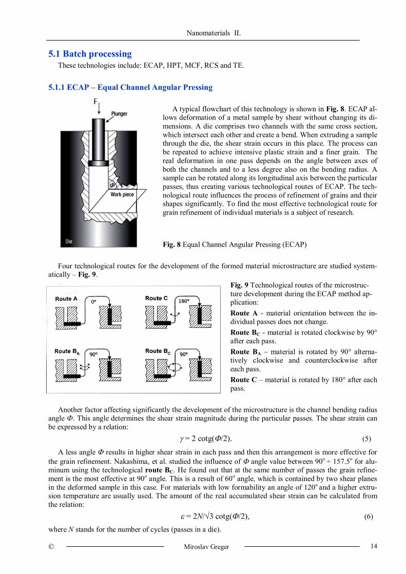
A typical flowchart of this technology is shown in Fig. 8. ECAP al-
lows deformation of a metal sample by shear without changing its di-mensions. A die comprises two channels with the same cross section, which intersect each other and create a bend. When extruding a sample through the die, the shear strain occurs in this place. The process can be repeated to achieve intensive plastic strain and a finer grain. The real deformation in one pass depends on the angle between axes of both the channels and to a less degree also on the bending radius. A sample can be rotated along its longitudinal axis between the particular passes, thus creating various technological routes of ECAP. The tech-nological route influences the process of refinement of grains and their shapes significantly. To find the most effective technological route for grain refinement of individual materials is a subject of research. Fig. 8 Equal Channel Angular Pressing (ECAP)
Four technological routes for the development of the formed material microstructure are studied system-atically – Fig. 9.
Fig. 9 Technological routes of the microstruc-ture development during the ECAP method ap-plication: Route A - material orientation between the in-dividual passes does not change. Route BC - material is rotated clockwise by 90° after each pass. Route BA – material is rotated by 90° alterna-tively clockwise and counterclockwise after each pass. Route C – material is rotated by 180° after each pass.
Another factor affecting significantly the development of the microstructure is the channel bending radius angle Ф. This angle determines the shear strain magnitude during the particular passes. The shear strain can be expressed by a relation:
= 2 cotg(/2). (5)
A less angle results in higher shear strain in each pass and then this arrangement is more effective for the grain refinement. Nakashima, et al. studied the influence of angle value between 90o ÷ 157.5o for alu-minum using the technological route BC. He found out that at the same number of passes the grain refine-ment is the most effective at 90o angle. This is a result of 60o angle, which is contained by two shear planes in the deformed sample in this case. For materials with low formability an angle of 120o and a higher extru-sion temperature are usually used. The amount of the real accumulated shear strain can be calculated from the relation:
= 2N/3 cotg(/2), (6)
where N stands for the number of cycles (passes in a die).
Nanomaterials II.
© Miroslav Greger 15
The microstructure development during the ECAP method was to the great extent studied only for mate-
rials with a face centered cubic lattice (Al, Cu) and with a hexagonal close packed lattice (Ti, Mg, Zn). A lattice of these metals contains few slip systems and the strain is influenced by a value of stacking fault ener-gy. Metals with a medium to high value of the stacking fault energy (Al, Cu) are deformed above all by slip mechanisms, while metals with low values of the stacking fault energy (Ag) are deformed mainly by twin-ning.
Metals with a body centered cubic lattice (Ni, Fe) have more slip systems, such as {110}<111>, {112}<111> and {123}<111>, therefore they are deformed by slip mechanisms. In the meanwhile, the re-search of the ECAP method for forming metals with the body centered cubic lattice is of a limited extent, above all due to low formability of these metals at low and medium temperatures.
The ECAP method has been still developed. Improved conditions of friction between the deformed sam-ple and inner surface of the die resulted in obtaining an ultra-fine grained structure in materials with low formability, such as W and Ti.
For example, ultra-fine grained bars with a diameter of 30 mm and length of 150 mm were manufactured from Ti. During the rod forming, the back-pressure on the formed material was also used, which increased formability of the used material significantly. Also, a rotational die was developed, the use of which elimi-nates a need to perform the extrusion of the entire sample and to re-insert it into the die between the particu-lar passes. A device which is a modification of the ECAP method has been installed in the RMSTC laborato-ry (VŠB – Technical University of Ostrava). The equipment is used for forming of long rods (the Conform technology).
5.1.2 HPT – High Pressure Torsion
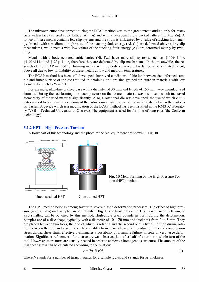
A flowchart of this technology and the photo of the real equipment are shown in Fig. 10.
Fig. 10 Metal forming by the High Pressure Tor-sion (HPT) method
Unconstrained HPT Constrained HPT
The HPT method belongs among favourite severe plastic deformation processes. The effect of high pres-sure (several GPa) on a sample can be unlimited (Fig. 10) or limited by a die. Grains with sizes to 10 nm, or also smaller, can be obtained by this method. High-angle grain boundaries form during the deformation. Samples are of a disc shape, typically with a diameter of 10 ÷ 20 mm and thickness from 2 to 5 mm. They are placed between two tools, the one of which is rotating and the second one is fixed. Friction during rota-tion between the tool and a sample surface enables to increase shear strain gradually. Imposed compression stress during shear strain effectively eliminates a possibility of a sample failure, in spite of very large defor-mation. Significant refinement of the structure was observed just after half of a turn or a whole turn of the tool. However, more turns are usually needed in order to achieve a homogenous structure. The amount of the real shear strain can be calculated according to the relation:
= 2 N r/d, (7)
where N stands for a number of turns, r stands for a sample radius and t stands for its thickness.
Nanomaterials II.
© Miroslav Greger 16
The HPT method was used successfully for refinement of a microstructure of non-ferrous metals and al-loys, steels, composites and semiconductors. At present, HPT is only used for processing of small samples, it is limited to a laboratory research. 5.1.3 HPTT - High-Pressure Tube Twisting
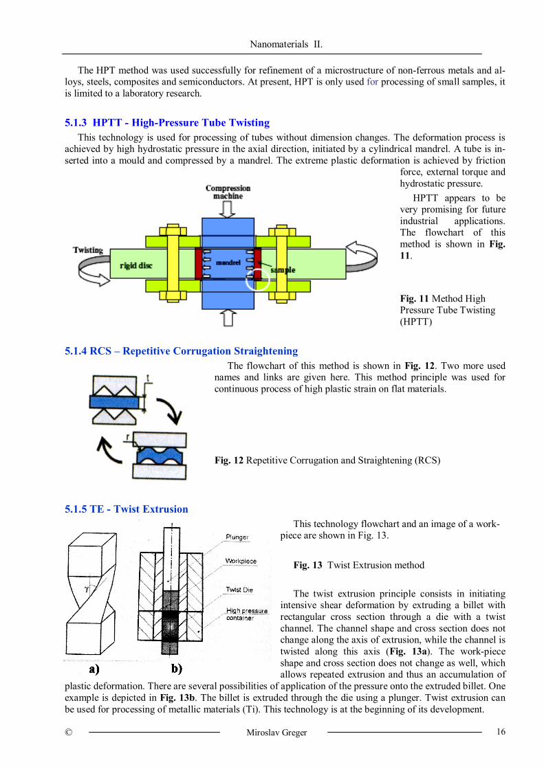
This technology is used for processing of tubes without dimension changes. The deformation process is achieved by high hydrostatic pressure in the axial direction, initiated by a cylindrical mandrel. A tube is in-serted into a mould and compressed by a mandrel. The extreme plastic deformation is achieved by friction
force, external torque and hydrostatic pressure.
HPTT appears to be very promising for future industrial applications. The flowchart of this method is shown in Fig. 11. Fig. 11 Method High Pressure Tube Twisting (HPTT)
5.1.4 RCS – Repetitive Corrugation Straightening The flowchart of this method is shown in Fig. 12. Two more used
names and links are given here. This method principle was used for continuous process of high plastic strain on flat materials. Fig. 12 Repetitive Corrugation and Straightening (RCS)
5.1.5 TE - Twist Extrusion
This technology flowchart and an image of a work-piece are shown in Fig. 13.
Fig. 13 Twist Extrusion method
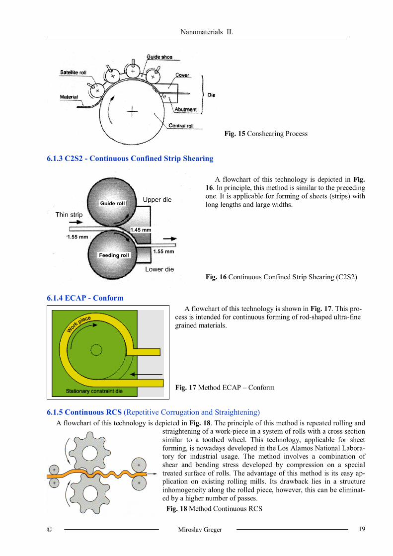
The twist extrusion principle consists in initiating intensive shear deformation by extruding a billet with rectangular cross section through a die with a twist channel. The channel shape and cross section does not change along the axis of extrusion, while the channel is twisted along this axis (Fig. 13a). The work-piece shape and cross section does not change as well, which allows repeated extrusion and thus an accumulation of
plastic deformation. There are several possibilities of application of the pressure onto the extruded billet. One example is depicted in Fig. 13b. The billet is extruded through the die using a plunger. Twist extrusion can be used for processing of metallic materials (Ti). This technology is at the beginning of its development.

Nanomaterials II.
© Miroslav Greger 17
Conclusion Batch processing technology:
ECAP – Equal Channel Angular Pressing HPT – High Pressure Torsion HPTT - High-Pressure Tube Twisting RCS – Repetitive Corrugation Straghtening TE - Twist Extrusion
Nanomaterials II.
© Miroslav Greger 18
6. CONTINUOUS METHODS OF PREPARATION OF ULTRA-FINE GRAINED MATERIALS
Time needed for studying: 90 minutes
Aim: After studying this chapter you will: Define the ARB process principle. Describe the particular technologies of preparation of nanocrystalline materials. Compare the processes of severe plastic deformation, get to know the most important SPD research
workplaces.
Explication
6.1 Continuous processes
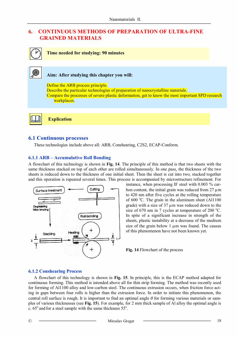
These technologies include above all: ARB, Conshearing, C2S2, ECAP-Conform. 6.1.1 ARB – Accumulative Roll Bonding A flowchart of this technology is shown in Fig. 14. The principle of this method is that two sheets with the same thickness stacked on top of each other are rolled simultaneously. In one pass, the thickness of the two sheets is reduced down to the thickness of one initial sheet. Then the sheet is cut into two, stacked together and this operation is repeated several times. This process is accompanied by microstructure refinement. For
instance, when processing IF steel with 0.003 % car-bon content, the initial grain was reduced from 27 m to 420 nm after five cycles at the rolling temperature of 600 oC. The grain in the aluminum sheet (Al1100 grade) with a size of 37 m was reduced down to the size of 670 nm in 7 cycles at temperature of 200 oC. In spite of a significant increase in strength of the sheets, plastic instability at a decrease of the medium size of the grain below 1 m was found. The causes of this phenomenon have not been known yet. Fig. 14 Flowchart of the process
6.1.2 Conshearing Process
A flowchart of this technology is shown in Fig. 15. In principle, this is the ECAP method adapted for continuous forming. This method is intended above all for thin strip forming. The method was recently used for forming of Al1100 alloy and low-carbon steel. The continuous extrusion occurs, when friction force act-ing in gaps between four rolls is higher than the extrusion force. In order to initiate this phenomenon, the central roll surface is rough. It is important to find an optimal angle for forming various materials or sam-ples of various thicknesses (see Fig. 15). For example, for 2 mm thick sample of Al alloy the optimal angle is c. 65o and for a steel sample with the same thickness 55o.
Nanomaterials II.
© Miroslav Greger 19
Fig. 15 Conshearing Process
6.1.3 C2S2 - Continuous Confined Strip Shearing
A flowchart of this technology is depicted in Fig.
16. In principle, this method is similar to the preceding one. It is applicable for forming of sheets (strips) with long lengths and large widths. Fig. 16 Continuous Confined Strip Shearing (C2S2)
6.1.4 ECAP - Conform
A flowchart of this technology is shown in Fig. 17. This pro-cess is intended for continuous forming of rod-shaped ultra-fine grained materials. Fig. 17 Method ECAP – Conform
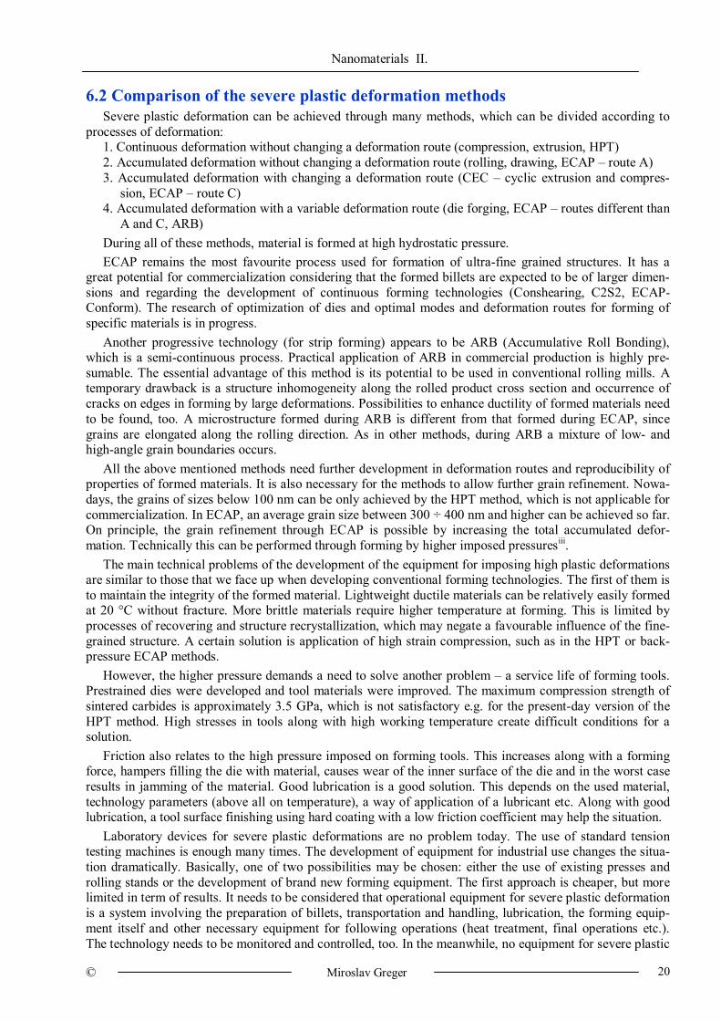
6.1.5 Continuous RCS (Repetitive Corrugation and Straightening)
A flowchart of this technology is depicted in Fig. 18. The principle of this method is repeated rolling and straightening of a work-piece in a system of rolls with a cross section similar to a toothed wheel. This technology, applicable for sheet forming, is nowadays developed in the Los Alamos National Labora-tory for industrial usage. The method involves a combination of shear and bending stress developed by compression on a special treated surface of rolls. The advantage of this method is its easy ap-plication on existing rolling mills. Its drawback lies in a structure inhomogeneity along the rolled piece, however, this can be eliminat-ed by a higher number of passes. Fig. 18 Method Continuous RCS
Upper die
Lower die
Thin strip
Feeding roll
Guide roll
1.55 mm
1.55 mm
1.45 mm
Nanomaterials II.
© Miroslav Greger 20
6.2 Comparison of the severe plastic deformation methods Severe plastic deformation can be achieved through many methods, which can be divided according to
processes of deformation: 1. Continuous deformation without changing a deformation route (compression, extrusion, HPT) 2. Accumulated deformation without changing a deformation route (rolling, drawing, ECAP – route A) 3. Accumulated deformation with changing a deformation route (CEC – cyclic extrusion and compres-
sion, ECAP – route C) 4. Accumulated deformation with a variable deformation route (die forging, ECAP – routes different than
A and C, ARB) During all of these methods, material is formed at high hydrostatic pressure. ECAP remains the most favourite process used for formation of ultra-fine grained structures. It has a
great potential for commercialization considering that the formed billets are expected to be of larger dimen-sions and regarding the development of continuous forming technologies (Conshearing, C2S2, ECAP-Conform). The research of optimization of dies and optimal modes and deformation routes for forming of specific materials is in progress.
Another progressive technology (for strip forming) appears to be ARB (Accumulative Roll Bonding), which is a semi-continuous process. Practical application of ARB in commercial production is highly pre-sumable. The essential advantage of this method is its potential to be used in conventional rolling mills. A temporary drawback is a structure inhomogeneity along the rolled product cross section and occurrence of cracks on edges in forming by large deformations. Possibilities to enhance ductility of formed materials need to be found, too. A microstructure formed during ARB is different from that formed during ECAP, since grains are elongated along the rolling direction. As in other methods, during ARB a mixture of low- and high-angle grain boundaries occurs.
All the above mentioned methods need further development in deformation routes and reproducibility of properties of formed materials. It is also necessary for the methods to allow further grain refinement. Nowa-days, the grains of sizes below 100 nm can be only achieved by the HPT method, which is not applicable for commercialization. In ECAP, an average grain size between 300 ÷ 400 nm and higher can be achieved so far. On principle, the grain refinement through ECAP is possible by increasing the total accumulated defor-mation. Technically this can be performed through forming by higher imposed pressuresiii.
The main technical problems of the development of the equipment for imposing high plastic deformations are similar to those that we face up when developing conventional forming technologies. The first of them is to maintain the integrity of the formed material. Lightweight ductile materials can be relatively easily formed at 20 °C without fracture. More brittle materials require higher temperature at forming. This is limited by processes of recovering and structure recrystallization, which may negate a favourable influence of the fine-grained structure. A certain solution is application of high strain compression, such as in the HPT or back-pressure ECAP methods.
However, the higher pressure demands a need to solve another problem – a service life of forming tools. Prestrained dies were developed and tool materials were improved. The maximum compression strength of sintered carbides is approximately 3.5 GPa, which is not satisfactory e.g. for the present-day version of the HPT method. High stresses in tools along with high working temperature create difficult conditions for a solution.
Friction also relates to the high pressure imposed on forming tools. This increases along with a forming force, hampers filling the die with material, causes wear of the inner surface of the die and in the worst case results in jamming of the material. Good lubrication is a good solution. This depends on the used material, technology parameters (above all on temperature), a way of application of a lubricant etc. Along with good lubrication, a tool surface finishing using hard coating with a low friction coefficient may help the situation.
Laboratory devices for severe plastic deformations are no problem today. The use of standard tension testing machines is enough many times. The development of equipment for industrial use changes the situa-tion dramatically. Basically, one of two possibilities may be chosen: either the use of existing presses and rolling stands or the development of brand new forming equipment. The first approach is cheaper, but more limited in term of results. It needs to be considered that operational equipment for severe plastic deformation is a system involving the preparation of billets, transportation and handling, lubrication, the forming equip-ment itself and other necessary equipment for following operations (heat treatment, final operations etc.). The technology needs to be monitored and controlled, too. In the meanwhile, no equipment for severe plastic
Nanomaterials II.
© Miroslav Greger 21
deformation runs in regular operational conditions. Some methods are relatively near to this target, above all for forming of aluminum alloys.
6.3 Research of steels with ultra-fine grained and nanocrystalline structure The main motivation for the research of the given steels is their potential application in automotive indus-
try, because they may provide an excellent combination of properties (strength and toughness). Compared to works performed with aluminum alloys (applications in aircraft and space industry and also in cars) and with titanium alloys (applications in medicine), the research of production processes for ultra-fine grained steels and study of their properties is performed in a substantially less extent.
6.4 The most important research workplaces Institutions concerned with the research of ultra-fine grained and nanostructured steels: o Department of Metallurgy and Materials Science Hanyang University, Ansan, Korea, Prof. Shin Dong Hyuk; [email protected] o Institute o Physics of Advanced Materials Ufa State Aviation Technical University, Ufa Russia, Prof. Valiev Ruslan Z., Stolyarev Vladimir, Raab Georgij [email protected]; [email protected]; [email protected] o Department of Plastic Deformation of Special Alloys Moscow State Institute of Steel and Alloys –Technological University, Moscow, Russia, Prof. Dobatkin Sergej V.; [email protected] o Department of Materials Science and Technology Nanjing University of Science and Technology, Nanjing, China, Prof. Wang Jingtao o Technology School of Metallurgical Engineering Xian University of Architecture and Technology, Xian, China, Prof. Zhao Xicheng o Department of Production systems Engineering Toyohashi University of Technology, Toyohashi, Japan, Prof. Umemoto Minoru o Department of Adaptive Machine Systems Osaka University, Osaka, Japan, Prof. Tsuji Nobuhiro; [email protected] o Department of Aerospace and Mechanical Engineering University of Southern California, Los Angeles, USA, Prof. Langdon Terrence G., [email protected] o Division of Advanced Materials Science and Engineering Hanbat National University, Taejon, Korea, Prof. Park Kyaung-Tae o Division of Materials Design, Faculty of Materials Science and EngineeringnWarsaw University of Technology, Warzaw, Poland, L. Olejnik, K. J. Kurzydlowski, [email protected]
At the VŠB - Technical University of Ostrava, the development of nanotechnologies using the severe plastic deformation is performed in the workplace at the Department of Materials Forming within the frame-work of the solved project MPO Impuls, FI-IM/033 “Research and utilization of nanotechnologies and the manufacture of nanostructured materials of high strength for modern constructions” (2004-2007) and GA CR project no. 106/09/1598 „Structure and properties of titanium for dental implants” (2009-2011).
The subject of the research within the project “Impuls” was the research and development of metal mate-rials with a structure in submicron and nanometric region. The research activities were focused on studying processes and mechanisms leading to creating ultra-fine grained microstructures using extreme deformations (ε = 2 ÷ 16). This way, bulk materials were prepared in order to investigate the physical-metallurgical princi-ple of the development of ultra-fine grained structures (nanostructures) and possibilities for preserving the nanostructure stability and accompanying mechanical properties of metal materials (Cu; Ti, Al, Mg alloys; plain and high-quality steels) at elevated temperatures with application of alloying methods and thermo-
Nanomaterials II.
© Miroslav Greger 22
mechanical processing of the obtained nanostructures. For preparation of bulk metal materials with a submi-croscopic structure (or nanostructure), the following technologies were used:
ECAP - (Equal Channel Angular Pressing) – extrusion through a channel’s two parts with a bending con-taining an angle of 90°, 105°
ARB - Accumulative Roll Bonding CEC - Cyclic Extrusion Compression C2S2 – Continuous Confined Strip Shearing A combination of powder metallurgy methods and CEC, ECAP In order to keep stability of ultra-fine grained structures at elevated temperatures, thermo-mechanical pro-
cessing in a combination with alloying and solution annealing was performed (additional hardening by effect of alloying elements and precipitation during plastic deformation under hot condition, or under cold condi-tion). To avoid thermal degradation of the microstructure of hardened materials, a repeated thermo-mechanical processing was applied subsequently.
Investigation and analysis of the severe plastic deformation and an influence of parameters of this method (total deformation, strain rate, temperature) on the formation and thermal stability of ultra-fine grained struc-tures were applied for various metals and alloys (Al, Cu, Mg and various steels).
The following methods were used for the evaluation of assets of the severe plastic deformation (SPD) for creating fine-grained structures: optical microscopy, electron microscopy and X-ray and neutron diffraction (evaluation of the crystallographic texture and development of micro-deformations). Further, microhardness, physical and mechanical properties and superplasticity were evaluated and documented.
Conclusion Continuous methods Severe Plastic deformation:
ARB – Accumulative Roll Bonding Conshearing Process C2S2 - Continuous Confined Strip Shearing ECAP - Conform Continuous RCS (Repetitive Corrugation and Straightening
Nanomaterials II.
© Miroslav Greger 23
7. CONCLUSION
Time needed for studying: 60 minutes
Aim: After studying this chapter you will: Define the mechanism of plastic deformation in nanostructured materials. Describe the research and development of new technologies of preparation of ultra-fine grained
and nanostructured materials. Specify the particular SPD technologies for different metal materials. Determine mechanical properties of nanostructured and ultra-fine grained materials.
Explication
The research and development of steels with ultra-fine grained and nanocrystalline structures is motivated by utilization of their very high strength properties for components, above all in the automotive industry. The present-day drawback is the achieved low ductility of these steels. The research is performed in the world-wide scale only in a limited number of academic workplaces. However, workplaces in Asia (Korea, China, Japan) have strong relationships with industrial enterprises supporting this research.
From the point of view of practical application of the above mentioned steels, the main problem is a size of the formed work-piece, reproducibility of the technology and especially the need to ensure mass produc-tion. According to the available information, the developing continuous methods of severe plastic defor-mation have been practically usable only for easily formable materials (Al alloys etc.) so far.
A next step in the research of ultra-fine grained steels is to continue the development of the higher productivity ECAP equipment, such as the C2S2 and ECAP-Conform methods. When developing the equipment, the patent situation needs to be taken into account (see the patents list on www.nanospd.org). Together with the development of the equipment, the research needs to be performed to develop optimal forming technologies through the ECAP method for selected steel grades in order to achieve satisfactory mechanical properties.
ECAP (under cold, semi-hot and hot condition) and ARB (semi continuous process) have been the most frequently used methods for preparation of ultra-fine grained steels of larger dimensions so far. According to the available information, only works on laboratory devices are performed. The subject of the research is particularly investigation of the microstructure growth in steels of different types (above all IF steels, low-carbon steels and pearlitic steels).
The plastic deformation mechanism in ultra-fine grained steels differs from mechanisms acting during de-formation of Al, Cu and Ti. The main mechanism is shear banding and formation of nanograins inside bands.
Several-fold increased strength values are achieved after the ECAP deformation in steels. For the time be-ing, satisfactory ductility values are an exception. The ECAP method results depend on lots of factors (initial structure, forming temperature, deformation route, strain rate, lubrication, die design etc.).
Conclusion The ECAP method is most frequently used for preparation of ultra-fine grained materials of larger
dimensions, the HPT method is most frequently used for preparation of nanostructured materials, the SPD methods are mainly used for laboratory equipment, the main mechanism of grain refinement is shear strain, several-fold increased strength values are achieved after the ECAP deformation, the SPD method results depend on the initial structure, deformation temperature, deformation
route, strain rate, lubrication, tool design.
Nanomaterials II.
© Miroslav Greger 24
LITERATURE
References to the Chapter 2 PETCH, N.J. J. Iron Steel Inst., 174, 1953, p. 25. HALL, E.O. Proc. Roy. Soc., 64B, 1951, p. 474. MASUMURA, R.A. et al. Acta Mater., 46, 1998, p. 4527. RJABUCHIN, V.B. Fizika Metallov i Metallovedenije, 43, 1995, p. 3027. PALUMBO, G. et al. Scripta Metall. Mater., 24, 1990, p. 1347. GRJAZNOV, V.G. et al. J. Mat. Sci., 38, 1993, p. 4359. GLEITER, H. Progr. Mat. Sci., 33,1989, p. 33.
References to the Chapter 3 LU, L. et al. Adv. Eng. Mat., 3, 2001, p. 663. XU, Ch. et al. Adv. Eng. Mat., 5, 2003, p. 359. MISHRA, R. S. et al. JOM, Jan. 1999, p. 37.
References to the Chapter 4 KIM, B. N. Nature, 413, 2001, p. 288. LIU, K.W. et al. Acta Mater., 49, 2001, p. 395.
References to the Chapter 5 VALIEV, R. Z. et al. Progr.Mat.Sci., 45, 2000, p. 103. UMEMOTO, M. et al. Ultrafine Grained Materials. Ed. by Zhu Y.T. et al. TMS,
Warrendale, PA, 2004, p. 241. ZHU, Y.T. et al. Mat. Sci. Eng., A291, 2000, p. 46. NAKASHIMA, K. et al. Acta Mater., 46, 1998, p. 1589. LOWE, T.C. et al. JOM, 56, Oct. 2004, p. 66. BELGEYZIMER, V. et al. Ultrafine Grained Materials. Ed. by Zhu Y.T. et al,
TMS, PA, Warrendale, PA, 2002, p. 356.
References to the Chapter 6 VALIEV, R.Z. et al. Progr. Mat. Sci., 45, 2000, p. 103. TSUJI, N. et al. Nanomaterials by Severe Plastic Deformation. Ed. M.J. Zehet-
bauer and R.Z. Valiev, Wiley-VCH, Weinheim, 2004, p. 479. UTSUNOMIYA H. et al. Ultrafine Grained Materials III. Ed. by Zhu Y.T. et
al., TMS, Warrendale, PA, 2004, p. 149. RAAB, G.J. et al. Mat. Sci. Eng., A328, 2004, p. 30. ZHU, Y.T. et al. Metall. Mater. Trans., 32A, 2001, p. 1559. ZEHETBAUER, M.J. et al. Adv. Eng. Mat., 5, 2003, p. 45.