Embed Size (px)
Citation preview
By
Dr. Jay Lindly Dr. Andrew Graettinger
Dr. Philip Johnson Mr. Michael Sherer Mr. Kyle Johnson
Department of Civil, Construction, and Environmental Engineering
The University of Alabama Tuscaloosa, Alabama
Prepared by
UTCA University Transportation Center for Alabama
The University of Alabama, The University of Alabama at Birmingham, and The University of Alabama in Huntsville
ALDOT Report Number 930-836 UTCA Report Number 12401
March 2015
Natural Gas Encasement for Highway Crossings
UTCA Theme: Management and Safety of Transportation Systems
About UTCA The University Transportation Center for Alabama (UTCA) is headquartered in the
Department of Civil, Construction, and Environmental Engineering at the University of Alabama (UA).
Interdisciplinary faculty members perform research, education, and technology-transfer projects using funds
provided by UTCA and external sponsors.
Mission Statement and Strategic Plan The mission of UTCA is “to advance the technology and
expertise in the multiple disciplines that comprise transportation through the mechanisms of education,
research, and technology transfer while serving as a university-based center of excellence.”
The UTCA strategic plan contains six goals that support this mission:
Education – conduct a multidisciplinary program of coursework and experiential learning that
reinforces the theme of transportation;
Human Resources – increase the number of students, faculty and staff who are attracted to and
substantively involved in the undergraduate, graduate, and professional programs of UTCA;
Diversity – develop students, faculty and staff who reflect the growing diversity of the US workforce
and are substantively involved in the undergraduate, graduate, and professional programs of
UTCA;
Research Selection – utilize an objective process for selecting and reviewing research that
balances the multiple objectives of the program;
Research Performance – conduct an ongoing program of basic and applied research, the products
of which are judged by peers or other experts in the field to advance the body of knowledge in
transportation; and
Technology Transfer – ensure the availability of research results to potential users in a form that
can be directly implemented, utilized or otherwise applied.
Theme The UTCA theme is “MANAGEMENT AND SAFETY OF TRANSPORTATION SYSTEMS.” UTCA concentrates
upon the highway and mass transit modes but also conducts projects featuring rail, waterway, air, and other
transportation modes as well as intermodal issues.
Acknowledgement This project was sponsored by Alabama Department of Transportation (ALDOT).
UTCA is grateful for ALDOT’s continued encouragement and support.
Disclaimer The contents of this report reflect the views of the authors, who are responsible for the facts
and the accuracy of the data presented herein. The contents do not necessarily reflect the official views or
policies of Alabama DOT, the University of Alabama, or UTCA, and they assume no liability for the contents
or use thereof. This report does not constitute a standard, specification, or regulation. Comments contained
in this report related to specific testing equipment and materials should not be considered an endorsement
of any commercial product or service; no such endorsement is intended or implied.
University Transportation Center for Alabama
i
Natural Gas Encasement for Highway Crossings
By
Dr. Jay Lindly Dr. Andrew Graettinger
Dr. Philip Johnson Mr. Michael Sherer Mr. Kyle Johnson
Department of Civil, Construction, and Environmental Engineering
The University of Alabama Tuscaloosa, Alabama
Prepared by
UTCA University Transportation Center for Alabama
The University of Alabama, The University of Alabama at Birmingham, and The University of Alabama in Huntsville
UTCA Report Number 12401
March 2015
ii
Technical Report Documentation Page 1. Report No.
2. Government Accession No.
3. Recipient Catalog No.
4. Title and Subtitle Natural Gas Encasement for Highway Crossings
5. Report Date March 2015 6. Performing Organization Code
7. Author(s) Dr. Jay Lindly, Dr. Andrew Graettinger, Dr. Philip Smith, Mr. Michael Sherer, Mr. Kyle Johnson
8. Performing Organization Report No. UTCA Final Report Number 12401
9. Performing Organization Name and Address University Transportation Center for Alabama Department of Civil, Construction & Environmental Engineering The University of Alabama, Box 870205 Tuscaloosa, AL 35487-0205
10. Work Unit No. (TRAIS) 11. Contract or Grant No. ALDOT Research Project 930-836
12. Sponsoring Agency Name and Address Alabama Department of Transportation 1409 Coliseum Boulevard Montgomery, AL 36110
13. Type of Report and Period Covered 14. Sponsoring Agency Code
15. Supplementary Notes
16. Abstract The University Transportation Center for Alabama researchers examined the Alabama Department of Transportation’s current policy regarding the encasement of natural gas and hazardous liquid pipelines at roadway crossings. The group collected information from a variety of sources regarding the benefits and drawbacks of encasement, including current standards, state policies, interviews with utility company personnel and utility contractor personnel, academic and non-academic publications, and gas pipeline incident reports. Though PHMSA incident reports indicate that encasement reduces excavation damages, the group recommended that the encasement of natural gas and hazardous liquid pipelines should not be mandatory at highway crossings except for special situations already cited in the ALDOT Utilities Manual. Instead, natural gas and hazardous material pipeline designers should follow the Code of Federal Regulations (CFR) Title 49 Volume 3 -- Parts 192 and 195, respectively -- which by reference includes all the necessary standards for pipeline design. The following findings support the conclusions:
• PHMSA recommends uncased crossings where practicable, • ASME 31.4 specifies that uncased crossings are “preferred” for hazardous liquid pipelines, • NACE International (formerly the National Association of Corrosion Engineers) considers casings a
corrosion hazard and recommends against them, • Though costs vary by installation, a cased crossing may typically cost twice as much as an equivalent
uncased crossing • Several hypothesized benefits of casing (such as usefulness for replacing damaged pipes at road crossings)
have not been proven in service, • The risk associated with uncased crossings appears to be orders of magnitude below acceptable limits, and • The majority of city and local road crossings in Alabama are uncased to no apparent detriment.
17. Key Words Cased, casing, encasement
18. Distribution Statement
19. Security Classification (of this report)
Unclassified
20. Security Classification (of this page)
Unclassified
21. No. of pages
22. Price
iii
Contents
Page
Executive Summary ........................................................................................................... vi Chapter 1 - Introduction ...................................................................................................... 1 Chapter 2 – Specifications/Codes ....................................................................................... 2
2.1 Standards ................................................................................................................... 2 2.2 Codes and Regulations……………………………………………….……………. 2 2.3 Regulations that Apply to Pipelines Crossing Highways ........................................ 2 2.4 Standards that Apply to Gas Pipelines ..................................................................... 2 2.5 Standards that Apply to Hazardous Liquid Pipelines .............................................. 6 2.6 FHWA/AASHTO… ................................................................................................. 9 2.7 Study Utility Accommodation Manual Policies ..................................................... 10 2.8 Local Policies ........................................................................................................ 14
Chapter 3 – Benefits and Drawbacks of Encasement ....................................................... 15 3.1 The Benefits of Encasement .................................................................................. 15 3.2 The Drawbacks to Encasement .............................................................................. 16
Chapter 4 – Data Analysis ............................................................................................... 18 4.1 PHMSA Incident Reports ...................................................................................... 18 4.2 Quantity of Pipeline-Roadway Crossings and Risk ............................................... 23 4.3 Geographic Information Systems Analysis ........................................................... 24 4.4 Natural Gas Customers .......................................................................................... 26 4.5 Acceptable Risk ..................................................................................................... 27
Chapter 5 - Software ....................................................................................................... 29 Chapter 6 - Conclusions .................................................................................................... 31 References ......................................................................................................................... 33 Appendix A – Proposed Revsions to ALDOT Utility Manual ......................................... 35 Appendix B - Pipeline Stress Analysis ............................................................................. 44
iv
List of Tables
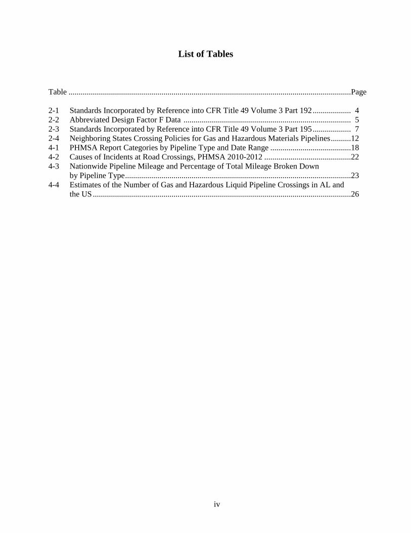
Table ............................................................................................................................................Page 2-1 Standards Incorporated by Reference into CFR Title 49 Volume 3 Part 192 ................... 4 2-2 Abbreviated Design Factor F Data ................................................................................... 5 2-3 Standards Incorporated by Reference into CFR Title 49 Volume 3 Part 195 ................... 7 2-4 Neighboring States Crossing Policies for Gas and Hazardous Materials Pipelines ..........12 4-1 PHMSA Report Categories by Pipeline Type and Date Range ........................................18 4-2 Causes of Incidents at Road Crossings, PHMSA 2010-2012 ...........................................22 4-3 Nationwide Pipeline Mileage and Percentage of Total Mileage Broken Down by Pipeline Type ................................................................................................................23 4-4 Estimates of the Number of Gas and Hazardous Liquid Pipeline Crossings in AL and the US ................................................................................................................................26
v
List of Figures
Figure Page 4-1 Culled Hazardous Liquid Incidents by Failure Type, 2010 - 2012 ........................ 19 4-2 Culled Transmission/Gathering Incidents by Failure Type, 2010 - 2012 .............. 20 4-3 Culled Distribution Incidents by Failure Type, 2010 – 2012 ................................. 20 4-4 State Highways, Transmission/Gathering Gas Pipelines, and Crossings in AL .... 25 4-5 Engineering Failures Plotted by Annual Probability of Failure vs. the Consequence of Failure .......................................................................................... 27 5-1 Pipeline Design Spreadsheet Created by Dr. P. Johnson ....................................... 30
vi
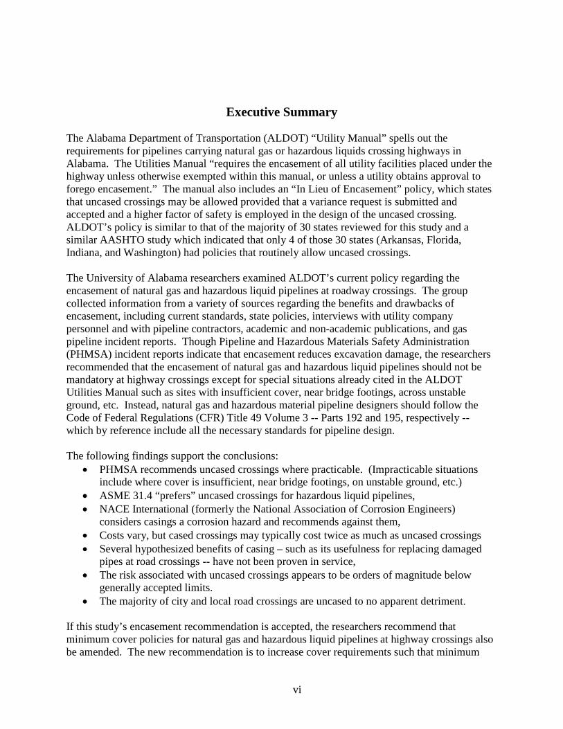
Executive Summary The Alabama Department of Transportation (ALDOT) “Utility Manual” spells out the requirements for pipelines carrying natural gas or hazardous liquids crossing highways in Alabama. The Utilities Manual “requires the encasement of all utility facilities placed under the highway unless otherwise exempted within this manual, or unless a utility obtains approval to forego encasement.” The manual also includes an “In Lieu of Encasement” policy, which states that uncased crossings may be allowed provided that a variance request is submitted and accepted and a higher factor of safety is employed in the design of the uncased crossing. ALDOT’s policy is similar to that of the majority of 30 states reviewed for this study and a similar AASHTO study which indicated that only 4 of those 30 states (Arkansas, Florida, Indiana, and Washington) had policies that routinely allow uncased crossings. The University of Alabama researchers examined ALDOT’s current policy regarding the encasement of natural gas and hazardous liquid pipelines at roadway crossings. The group collected information from a variety of sources regarding the benefits and drawbacks of encasement, including current standards, state policies, interviews with utility company personnel and with pipeline contractors, academic and non-academic publications, and gas pipeline incident reports. Though Pipeline and Hazardous Materials Safety Administration (PHMSA) incident reports indicate that encasement reduces excavation damage, the researchers recommended that the encasement of natural gas and hazardous liquid pipelines should not be mandatory at highway crossings except for special situations already cited in the ALDOT Utilities Manual such as sites with insufficient cover, near bridge footings, across unstable ground, etc. Instead, natural gas and hazardous material pipeline designers should follow the Code of Federal Regulations (CFR) Title 49 Volume 3 -- Parts 192 and 195, respectively -- which by reference include all the necessary standards for pipeline design. The following findings support the conclusions:
• PHMSA recommends uncased crossings where practicable. (Impracticable situations include where cover is insufficient, near bridge footings, on unstable ground, etc.)
• ASME 31.4 “prefers” uncased crossings for hazardous liquid pipelines, • NACE International (formerly the National Association of Corrosion Engineers)
considers casings a corrosion hazard and recommends against them, • Costs vary, but cased crossings may typically cost twice as much as uncased crossings • Several hypothesized benefits of casing – such as its usefulness for replacing damaged
pipes at road crossings -- have not been proven in service, • The risk associated with uncased crossings appears to be orders of magnitude below
generally accepted limits. • The majority of city and local road crossings are uncased to no apparent detriment.
If this study’s encasement recommendation is accepted, the researchers recommend that minimum cover policies for natural gas and hazardous liquid pipelines at highway crossings also be amended. The new recommendation is to increase cover requirements such that minimum
vii
cover requirements become 48 inches under ditches or 60 inches from the highway surface, whichever places the pipe facility deeper. This recommendation decreases the probability of damage from excavation and damage from the installation of sign supports and barrier rail posts.
Proposed revised text of the Utilities Manual as it relates to natural gas and hazardous liquid pipeline encasement policy can be found in Appendix A of this report.
1
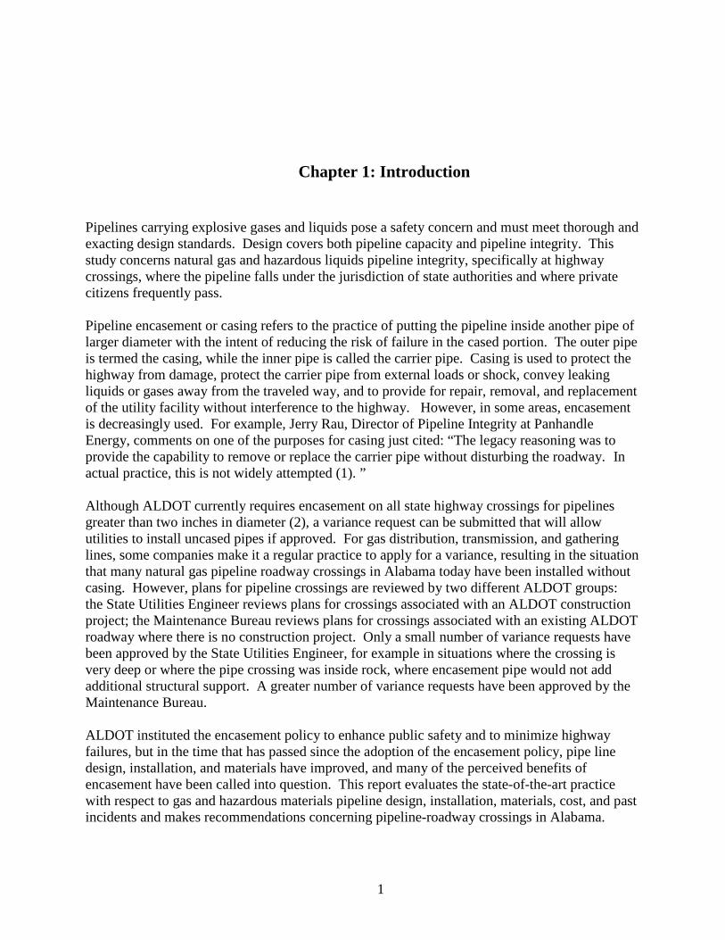
Chapter 1: Introduction
Pipelines carrying explosive gases and liquids pose a safety concern and must meet thorough and exacting design standards. Design covers both pipeline capacity and pipeline integrity. This study concerns natural gas and hazardous liquids pipeline integrity, specifically at highway crossings, where the pipeline falls under the jurisdiction of state authorities and where private citizens frequently pass. Pipeline encasement or casing refers to the practice of putting the pipeline inside another pipe of larger diameter with the intent of reducing the risk of failure in the cased portion. The outer pipe is termed the casing, while the inner pipe is called the carrier pipe. Casing is used to protect the highway from damage, protect the carrier pipe from external loads or shock, convey leaking liquids or gases away from the traveled way, and to provide for repair, removal, and replacement of the utility facility without interference to the highway. However, in some areas, encasement is decreasingly used. For example, Jerry Rau, Director of Pipeline Integrity at Panhandle Energy, comments on one of the purposes for casing just cited: “The legacy reasoning was to provide the capability to remove or replace the carrier pipe without disturbing the roadway. In actual practice, this is not widely attempted (1). ” Although ALDOT currently requires encasement on all state highway crossings for pipelines greater than two inches in diameter (2), a variance request can be submitted that will allow utilities to install uncased pipes if approved. For gas distribution, transmission, and gathering lines, some companies make it a regular practice to apply for a variance, resulting in the situation that many natural gas pipeline roadway crossings in Alabama today have been installed without casing. However, plans for pipeline crossings are reviewed by two different ALDOT groups: the State Utilities Engineer reviews plans for crossings associated with an ALDOT construction project; the Maintenance Bureau reviews plans for crossings associated with an existing ALDOT roadway where there is no construction project. Only a small number of variance requests have been approved by the State Utilities Engineer, for example in situations where the crossing is very deep or where the pipe crossing was inside rock, where encasement pipe would not add additional structural support. A greater number of variance requests have been approved by the Maintenance Bureau. ALDOT instituted the encasement policy to enhance public safety and to minimize highway failures, but in the time that has passed since the adoption of the encasement policy, pipe line design, installation, and materials have improved, and many of the perceived benefits of encasement have been called into question. This report evaluates the state-of-the-art practice with respect to gas and hazardous materials pipeline design, installation, materials, cost, and past incidents and makes recommendations concerning pipeline-roadway crossings in Alabama.
2
Chapter 2: Specifications/Codes
2.1 Standards Recognized authorities such as professional societies or trade organizations promulgate engineering standards to assure safety, reliability, and consistency in materials, components, and methods. By themselves, standards do not have the force of law; rather, they are accepted and applied by consensus. Further, standards evolve; practicing professionals continuously review and update standards based on new findings or experience. Safety and integrity of the facilities are of the utmost importance. 2.2 Codes and Regulations Codes and regulations are laws passed by federal, state, or local governments to ensure public safety in the built environment. Because the bodies that pass codes and regulations are not necessarily knowledgeable in technical matters, they often incorporate by reference standards that have been developed by technically-knowledgeable organizations. For instance, the ALDOT Utilities Manual (3) cites the Code of Federal Regulations (CFR), which includes some specific information on design of gas pipelines but also incorporates American Society of Mechanical Engineers (ASME) standards and other standards by reference. 2.3 Regulations that Apply to Pipelines Crossing Highways At the federal level, pipelines are regulated by CFR Title 49 Volume 3 Parts 191 (reporting), 192 (natural gas pipelines), and 195 (hazardous liquid pipelines). In addition, each state imposes regulations, and cities, towns, and counties may add additional levels of regulation. Federal regulations make reference to highway crossings of pipelines but do not require encasement, while the ALDOT Utilities Manual specifically calls for encasement (2). CFR Title 49 Volume 3 Part 192-TRANSPORTATION OF NATURAL AND OTHER GAS BY PIPELINE: MINIMUM FEDERAL SAFETY STANDARDS requires special treatment for road crossings compared to pipelines traveling cross-country, but it does not require encasement. The regulation does impose requirements for casings should casings be installed. CFR Title 49 Volume 3 Part 195-TRANSPORTATION OF HAZARDOUS LIQUIDS BY PIPELINE makes no reference to casings at crossings, nor does the regulation require any special pipeline design treatment at crossings. In the section on construction, the regulation does state that, “The pipe at each railroad or highway crossing must be installed so as to adequately withstand the dynamic forces exerted by anticipated traffic loads.” 2.4 Standards that Apply to Gas Pipelines As noted in foregoing sections, CFR Title 49 Volume 3 Part 192-TRANSPORTATION OF NATURAL AND OTHER GAS BY PIPELINE: MINIMUM FEDERAL SAFETY
3
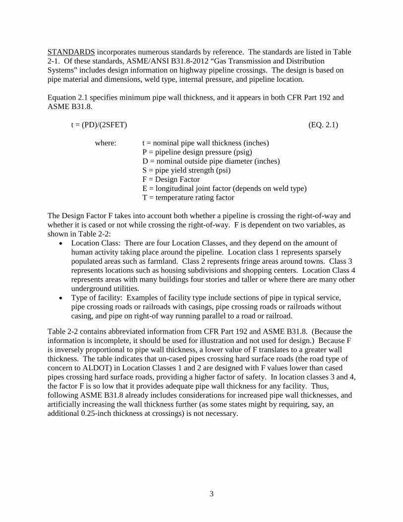
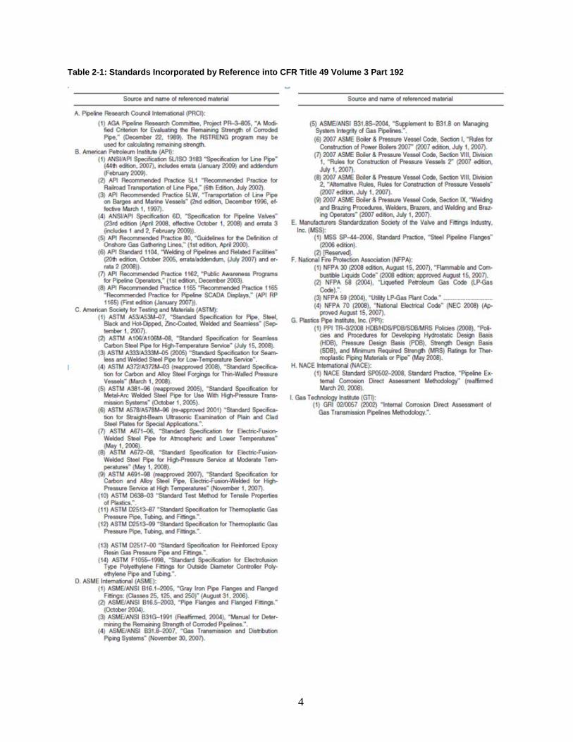
STANDARDS incorporates numerous standards by reference. The standards are listed in Table 2-1. Of these standards, ASME/ANSI B31.8-2012 “Gas Transmission and Distribution Systems” includes design information on highway pipeline crossings. The design is based on pipe material and dimensions, weld type, internal pressure, and pipeline location. Equation 2.1 specifies minimum pipe wall thickness, and it appears in both CFR Part 192 and ASME B31.8.
t = (PD)/(2SFET) (EQ. 2.1) where: t = nominal pipe wall thickness (inches) P = pipeline design pressure (psig) D = nominal outside pipe diameter (inches) S = pipe yield strength (psi) F = Design Factor E = longitudinal joint factor (depends on weld type) T = temperature rating factor The Design Factor F takes into account both whether a pipeline is crossing the right-of-way and whether it is cased or not while crossing the right-of-way. F is dependent on two variables, as shown in Table 2-2:
• Location Class: There are four Location Classes, and they depend on the amount of human activity taking place around the pipeline. Location class 1 represents sparsely populated areas such as farmland. Class 2 represents fringe areas around towns. Class 3 represents locations such as housing subdivisions and shopping centers. Location Class 4 represents areas with many buildings four stories and taller or where there are many other underground utilities.
• Type of facility: Examples of facility type include sections of pipe in typical service, pipe crossing roads or railroads with casings, pipe crossing roads or railroads without casing, and pipe on right-of way running parallel to a road or railroad.
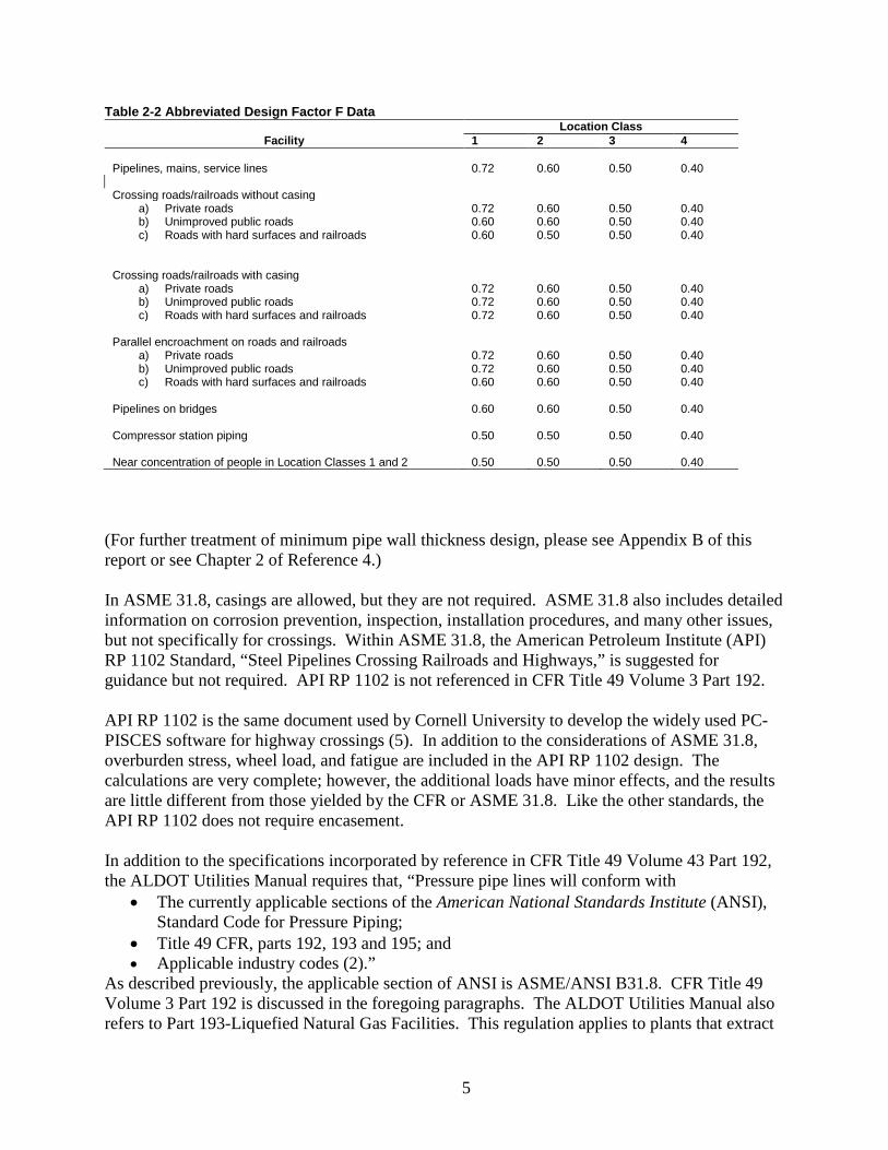
Table 2-2 contains abbreviated information from CFR Part 192 and ASME B31.8. (Because the information is incomplete, it should be used for illustration and not used for design.) Because F is inversely proportional to pipe wall thickness, a lower value of F translates to a greater wall thickness. The table indicates that un-cased pipes crossing hard surface roads (the road type of concern to ALDOT) in Location Classes 1 and 2 are designed with F values lower than cased pipes crossing hard surface roads, providing a higher factor of safety. In location classes 3 and 4, the factor F is so low that it provides adequate pipe wall thickness for any facility. Thus, following ASME B31.8 already includes considerations for increased pipe wall thicknesses, and artificially increasing the wall thickness further (as some states might by requiring, say, an additional 0.25-inch thickness at crossings) is not necessary.
4
Table 2-1: Standards Incorporated by Reference into CFR Title 49 Volume 3 Part 192
5
Table 2-2 Abbreviated Design Factor F Data Location Class
Facility 1 2 3 4 Pipelines, mains, service lines 0.72 0.60 0.50 0.40 Crossing roads/railroads without casing
a) Private roads b) Unimproved public roads c) Roads with hard surfaces and railroads
0.72 0.60 0.60
0.60 0.60 0.50
0.50 0.50 0.50
0.40 0.40 0.40
Crossing roads/railroads with casing
a) Private roads b) Unimproved public roads c) Roads with hard surfaces and railroads
0.72 0.72 0.72
0.60 0.60 0.60
0.50 0.50 0.50
0.40 0.40 0.40
Parallel encroachment on roads and railroads
a) Private roads b) Unimproved public roads c) Roads with hard surfaces and railroads
0.72 0.72 0.60
0.60 0.60 0.60
0.50 0.50 0.50
0.40 0.40 0.40
Pipelines on bridges 0.60 0.60 0.50 0.40 Compressor station piping 0.50 0.50 0.50 0.40 Near concentration of people in Location Classes 1 and 2 0.50 0.50 0.50 0.40
(For further treatment of minimum pipe wall thickness design, please see Appendix B of this report or see Chapter 2 of Reference 4.) In ASME 31.8, casings are allowed, but they are not required. ASME 31.8 also includes detailed information on corrosion prevention, inspection, installation procedures, and many other issues, but not specifically for crossings. Within ASME 31.8, the American Petroleum Institute (API) RP 1102 Standard, “Steel Pipelines Crossing Railroads and Highways,” is suggested for guidance but not required. API RP 1102 is not referenced in CFR Title 49 Volume 3 Part 192. API RP 1102 is the same document used by Cornell University to develop the widely used PC-PISCES software for highway crossings (5). In addition to the considerations of ASME 31.8, overburden stress, wheel load, and fatigue are included in the API RP 1102 design. The calculations are very complete; however, the additional loads have minor effects, and the results are little different from those yielded by the CFR or ASME 31.8. Like the other standards, the API RP 1102 does not require encasement. In addition to the specifications incorporated by reference in CFR Title 49 Volume 43 Part 192, the ALDOT Utilities Manual requires that, “Pressure pipe lines will conform with
• The currently applicable sections of the American National Standards Institute (ANSI), Standard Code for Pressure Piping;
• Title 49 CFR, parts 192, 193 and 195; and • Applicable industry codes (2).”
As described previously, the applicable section of ANSI is ASME/ANSI B31.8. CFR Title 49 Volume 3 Part 192 is discussed in the foregoing paragraphs. The ALDOT Utilities Manual also refers to Part 193-Liquefied Natural Gas Facilities. This regulation applies to plants that extract
6
liquefiable fractions from natural gas. Such plants operate within a fenced boundary, and while a state highway might pass by such a plant, it would not pass through one. Part 193 does not address road crossings at all; thus, Part 193 does not appear applicable to this study. Part 195-Transport of Hazardous Liquids by Pipeline is discussed in the following section titled “Standards that Apply to Liquid Pipelines.” The ALDOT Utilities Manual also includes the phrase “and applicable industry codes (3).” In practice, the CFR includes all applicable industry standards.
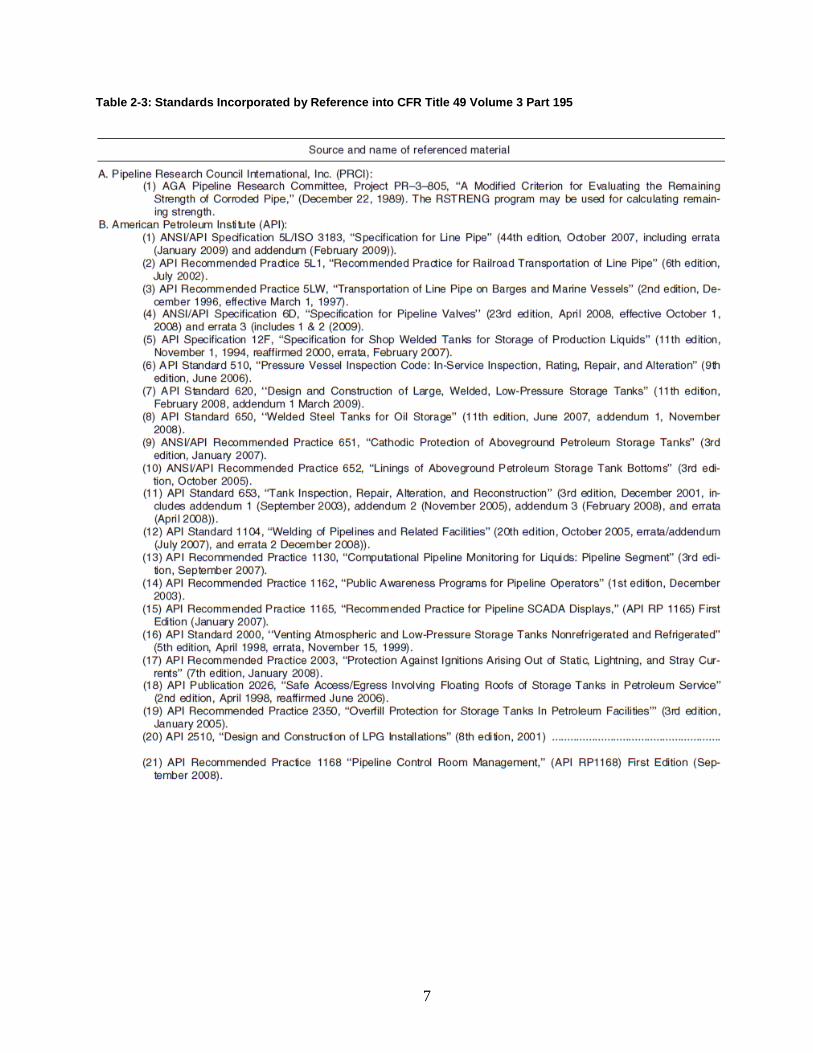
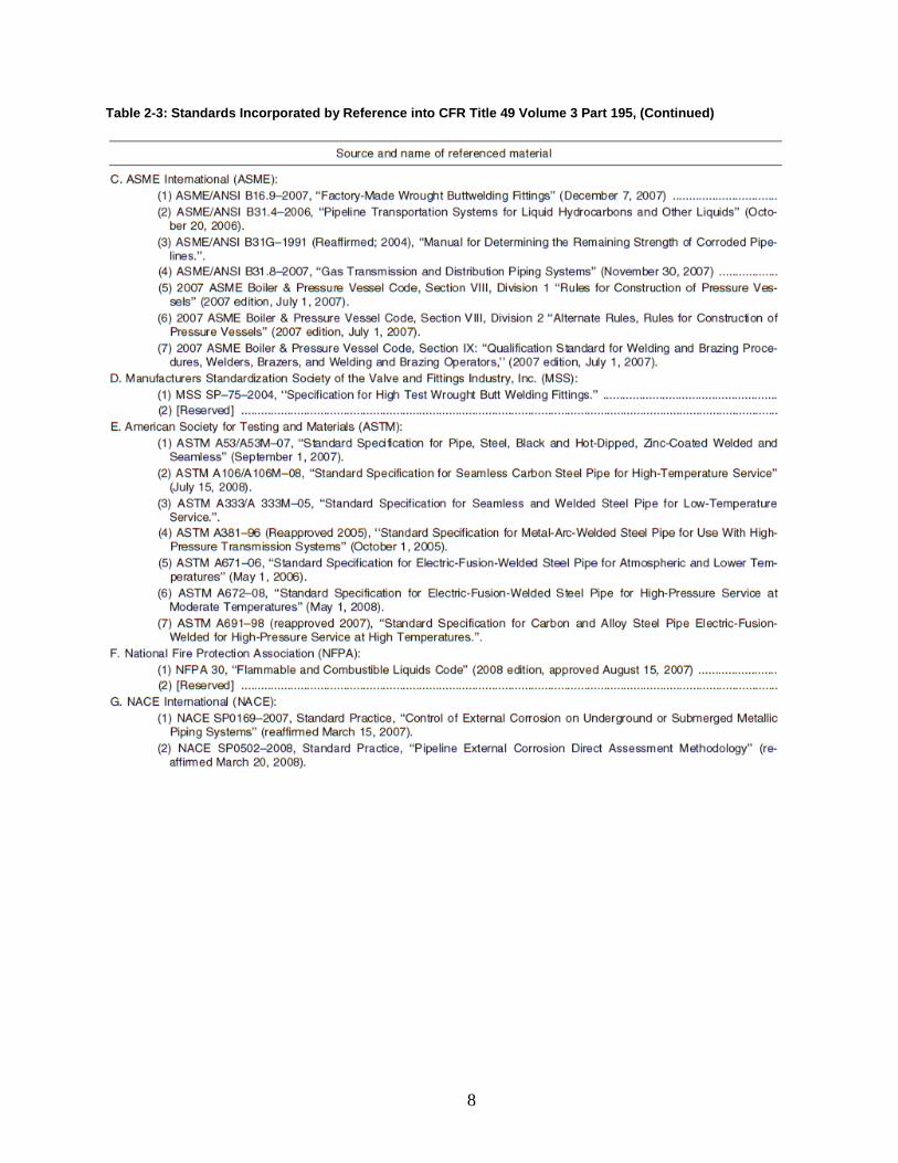
2.5 Standards that Apply to Hazardous Liquid Pipelines As noted in the foregoing sections, CFR Title 49 Volume 3 Part 195-Transportation of Hazardous Liquids by Pipeline incorporates numerous standards by reference. The standards are listed in Table 2-3. Of these, ASME/ANSI B31.8-2007 Gas Transmission and Distribution Systems, and ASME/ANSI B31.4 Pipeline Transmission Systems for Liquid Hydrocarbons and Other Liquids are the most applicable. ASME B31.8 has been discussed in the foregoing sections. ASME B31.4 does not require encasement at highway crossings; in fact, the 2012 standard actually recommends uncased pipe, as shown below (underlining provided by the authors):
“434.13.4 Railroad and Highway Crossings (a) The safety of the general public and the prevention of damage to the pipeline by reason of its location are primary considerations. The great variety of such crossings precludes standard design. The construction specifications shall cover the procedure for such crossings, based upon the requirements of the specific location. (b) Installation of uncased carrier pipe is preferred.”
ASME B31.4 states that its design is adequate for public safety under typical situations. However, it does list encasement as a possible alternative design for the “unusual external conditions” that may be encountered as described below:
“…in river crossings, offshore and inland coastal water areas, bridges, areas of heavy traffic, long self-supported spans, unstable ground, vibration, weight of special attachments, or forces resulting from abnormal thermal conditions. Some of the protective measures that the design may provide are encasing with steel pipe of larger diameter, adding concrete protective coating, adding a concrete cap, increasing the wall thickness, lowering the line to a greater depth, or indicating the presence of the line with additional markers.”
7
Table 2-3: Standards Incorporated by Reference into CFR Title 49 Volume 3 Part 195
8
Table 2-3: Standards Incorporated by Reference into CFR Title 49 Volume 3 Part 195, (Continued)
9
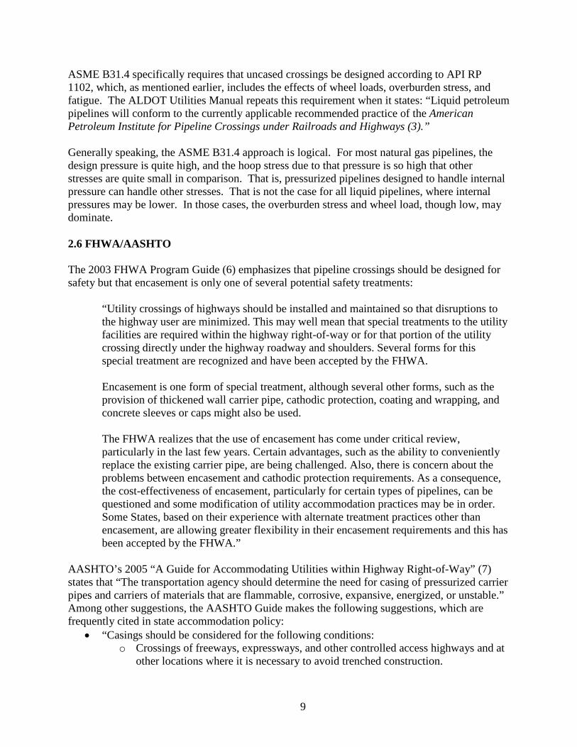
ASME B31.4 specifically requires that uncased crossings be designed according to API RP 1102, which, as mentioned earlier, includes the effects of wheel loads, overburden stress, and fatigue. The ALDOT Utilities Manual repeats this requirement when it states: “Liquid petroleum pipelines will conform to the currently applicable recommended practice of the American Petroleum Institute for Pipeline Crossings under Railroads and Highways (3).” Generally speaking, the ASME B31.4 approach is logical. For most natural gas pipelines, the design pressure is quite high, and the hoop stress due to that pressure is so high that other stresses are quite small in comparison. That is, pressurized pipelines designed to handle internal pressure can handle other stresses. That is not the case for all liquid pipelines, where internal pressures may be lower. In those cases, the overburden stress and wheel load, though low, may dominate. 2.6 FHWA/AASHTO The 2003 FHWA Program Guide (6) emphasizes that pipeline crossings should be designed for safety but that encasement is only one of several potential safety treatments:
“Utility crossings of highways should be installed and maintained so that disruptions to the highway user are minimized. This may well mean that special treatments to the utility facilities are required within the highway right-of-way or for that portion of the utility crossing directly under the highway roadway and shoulders. Several forms for this special treatment are recognized and have been accepted by the FHWA. Encasement is one form of special treatment, although several other forms, such as the provision of thickened wall carrier pipe, cathodic protection, coating and wrapping, and concrete sleeves or caps might also be used. The FHWA realizes that the use of encasement has come under critical review, particularly in the last few years. Certain advantages, such as the ability to conveniently replace the existing carrier pipe, are being challenged. Also, there is concern about the problems between encasement and cathodic protection requirements. As a consequence, the cost-effectiveness of encasement, particularly for certain types of pipelines, can be questioned and some modification of utility accommodation practices may be in order. Some States, based on their experience with alternate treatment practices other than encasement, are allowing greater flexibility in their encasement requirements and this has been accepted by the FHWA.”
AASHTO’s 2005 “A Guide for Accommodating Utilities within Highway Right-of-Way” (7) states that “The transportation agency should determine the need for casing of pressurized carrier pipes and carriers of materials that are flammable, corrosive, expansive, energized, or unstable.” Among other suggestions, the AASHTO Guide makes the following suggestions, which are frequently cited in state accommodation policy:
• “Casings should be considered for the following conditions: o Crossings of freeways, expressways, and other controlled access highways and at
other locations where it is necessary to avoid trenched construction.
10
o As protection for carrier pipe from external loads or shock either during or after construction of the highway.
o As a means of conveying leaking fluids or gases away from the area …..” • “Jacked or bored installations of coated carrier pipes should be encased. Exceptions may
be made where assurance can be provided against damage to the protective coating.” • “On uncased construction the carrier shall conform to the material and design
requirements of utility industry and governmental codes and standards. In addition, the carrier pipe should be designed to support the load of the highway plus superimposed loads thereon when the pipe is operated under all ranges of pressure from maximum internal to zero pressure. Such installations should employ a higher factor of safety in the design, construction, and testing than would normally be required for cased construction.”
• “Uncased crossing of welded steel pipelines which carry flammable, corrosive, expansive, energized, or unstable materials, particularly if carried at high pressure or potential, maybe permitted, provided additional protective measures are taken in lieu of encasement. Such measures would employ a higher factor of safety in the location, design, construction, and testing of the uncased-carrier pipe, including such features as increased depth of cover, thicker wall pipe, radiograph testing of welds, hydrostatic testing, coating and wrapping, and cathodic protection.”
2.7 State Utility Accommodation Manual Policies The ALDOT Utilities Manual spells out the requirements for pipelines crossing highways in Alabama. With regards to encasement of crossings, the Utilities Manual “requires the encasement of all utility facilities placed under the highway unless otherwise exempted within this manual, or unless a utility obtains approval to forego encasement.” The manual also includes an “In Lieu of Encasement” policy, which states that uncased crossings may be allowed provided that a variance request is submitted and accepted and a higher factor of safety is employed in the design of the uncased crossing. In fact, the CFR, the ASME Standards, and API RP 1102 do not always require higher factors of safety in uncased versus cased gas pipeline crossings. This was demonstrated previously in Table 2-2, where 1/F represents the safety factor. In the low population areas represented by Class Locations 1 and 2, uncased crossings of hard surfaced public roads do require a higher factor of safety than cased crossings (1.67 versus 1.39 for both Location Classes). However, in the more densely populated areas represented by Location Classes 3 and 4, the factor of safety for all steel pipelines is 2.0 and 2.5, respectively, and no additional thickness is deemed necessary regardless of encasement. Most states operate in the same mode as Alabama and require either encasement or that the utility obtain an encasement waver. However, with improvements in design, installation, and pipeline materials, this situation is changing in some states. Washington State ceased requiring encasement for gas pipelines in 2007, except in special circumstances (8). Conversations with representatives of the Washington DOT indicate that this change has not created a problem, but the state has not extended this policy to include hazardous liquid pipelines, where encasement is still required. Indiana states that crossings “may be cased or non-encased.” Regarding cover, Indiana states “All lines which are under or within 5.0 feet of the roadway will have a minimum depth of cover under the pavement of 4.0 feet for encased and non-encased lines (9).” For a
11
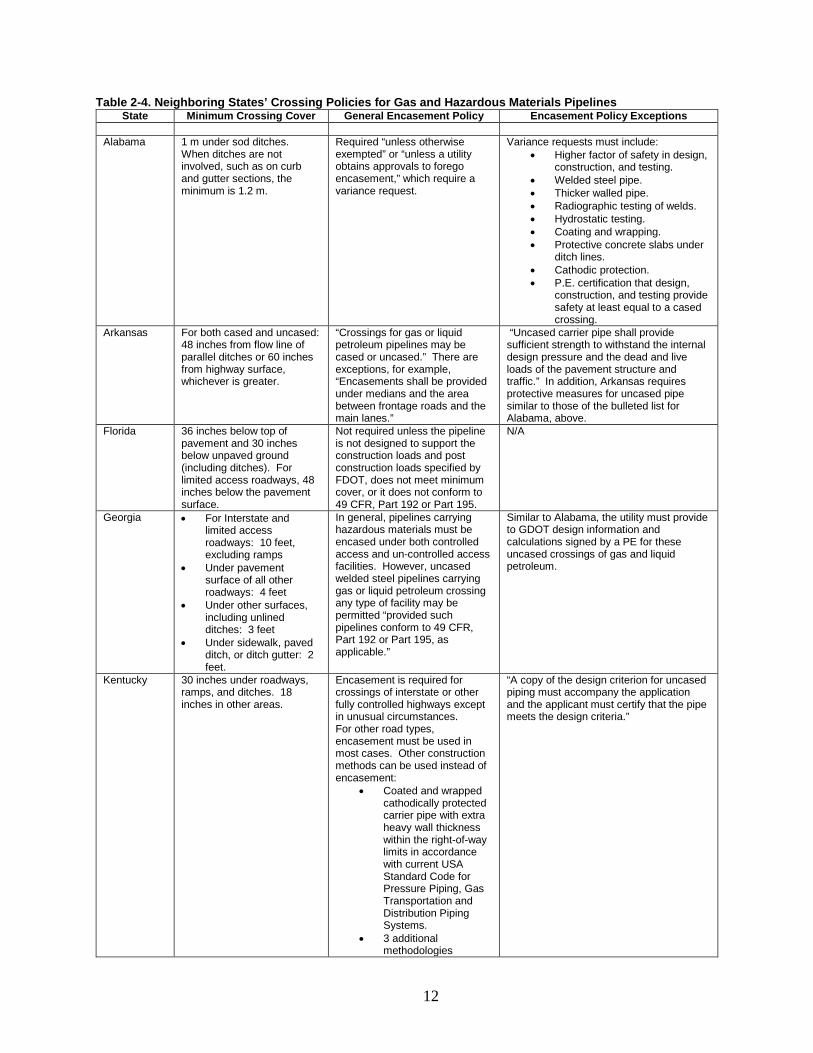
more in-depth treatment of different states’ policies, the reader may refer to “Guidelines for Utility Encasement Policy for Highway Crossings (4).” The UA research team conducted a review of seven nearby state policies, and the results are shown in Table 2-4. The table shows each state’s general policies for crossings of gas pipelines and other hazardous material pipelines; the table does not reflect unusual conditions such as where there is insufficient cover or where a pipe passes very close to a bridge footing. There are many similarities in state policies. For example, most states include some form of the following statements:
• “Pressure pipelines shall conform with the currently applicable section of The Standard Code for Pressure Piping of the American National Standards Institute, latest edition; Title 49 CFR, Parts 191, 192 and 195, latest version; and applicable industry codes, including current issues of ……..” (South Carolina)
• “Encasement or other suitable protection may also be required for any pipeline (1) with less than minimum bury, (2) near footings of bridges or other highway structures or across unstable or subsiding ground, or (3) near other locations where there may be a hazard.” (Alabama)
• “Pavements, shoulders, roadways or ramps can not be excavated by the open trench method except with the approval of the Department and Federal Highway Administration (where applicable).” (Kentucky)
However, state policies do vary regarding encasement policy, and the principle findings of the review follow:
• Two of the seven neighbor states reviewed – Arkansas and Florida – allow gas and hazardous material pipelines crossings to be installed cased or uncased.
• Five of the seven neighbor states – Georgia, Kentucky, Louisiana, South Carolina, and Tennessee – have policies similar to Alabama that normally require encased crossings but allow applications for waivers for uncased crossings. In general, the requests must contain calculations for thicker walled pipe and contain provisions for radiographic weld testing, hydrostatic testing, cathodic protection, etc., as shown in the table.
• Two of the neighbor states – Louisiana and Tennessee – require that “the wall thickness for natural gas and other hazardous material pipelines be at least two increments greater than that required by Federal DOT Title 49.” (Tennessee) UA researchers contacted Louisiana and Tennessee to inquire about the reasoning behind the “two increments greater” thickness requirement. LaDOTD personnel did not know the origins of the requirement but theorized that it might arise from Equation 2.1 in Section 2.4, where Design Factor F may increase twice: once with Location Class and a second time at a road crossing (see Table 2-2). TDOT personnel wrote that the thickness requirement was added “to increase the safety confidence level.”
• Minimum cover depth can be widely variable, for example 10 feet under Interstate and limited access freeways (Georgia) and two feet under drainage ditches for cased crossings (Louisiana).
12
Table 2-4. Neighboring States’ Crossing Policies for Gas and Hazardous Materials Pipelines State Minimum Crossing Cover General Encasement Policy Encasement Policy Exceptions
Alabama 1 m under sod ditches.
When ditches are not involved, such as on curb and gutter sections, the minimum is 1.2 m.
Required “unless otherwise exempted” or “unless a utility obtains approvals to forego encasement,” which require a variance request.
Variance requests must include: • Higher factor of safety in design,
construction, and testing. • Welded steel pipe. • Thicker walled pipe. • Radiographic testing of welds. • Hydrostatic testing. • Coating and wrapping. • Protective concrete slabs under
ditch lines. • Cathodic protection. • P.E. certification that design,
construction, and testing provide safety at least equal to a cased crossing.
Arkansas For both cased and uncased: 48 inches from flow line of parallel ditches or 60 inches from highway surface, whichever is greater.
“Crossings for gas or liquid petroleum pipelines may be cased or uncased.” There are exceptions, for example, “Encasements shall be provided under medians and the area between frontage roads and the main lanes.”
“Uncased carrier pipe shall provide sufficient strength to withstand the internal design pressure and the dead and live loads of the pavement structure and traffic.” In addition, Arkansas requires protective measures for uncased pipe similar to those of the bulleted list for Alabama, above.
Florida 36 inches below top of pavement and 30 inches below unpaved ground (including ditches). For limited access roadways, 48 inches below the pavement surface.
Not required unless the pipeline is not designed to support the construction loads and post construction loads specified by FDOT, does not meet minimum cover, or it does not conform to 49 CFR, Part 192 or Part 195.
N/A
Georgia • For Interstate and limited access roadways: 10 feet, excluding ramps
• Under pavement surface of all other roadways: 4 feet
• Under other surfaces, including unlined ditches: 3 feet
• Under sidewalk, paved ditch, or ditch gutter: 2 feet.
In general, pipelines carrying hazardous materials must be encased under both controlled access and un-controlled access facilities. However, uncased welded steel pipelines carrying gas or liquid petroleum crossing any type of facility may be permitted “provided such pipelines conform to 49 CFR, Part 192 or Part 195, as applicable.”
Similar to Alabama, the utility must provide to GDOT design information and calculations signed by a PE for these uncased crossings of gas and liquid petroleum.
Kentucky 30 inches under roadways, ramps, and ditches. 18 inches in other areas.
Encasement is required for crossings of interstate or other fully controlled highways except in unusual circumstances. For other road types, encasement must be used in most cases. Other construction methods can be used instead of encasement:
• Coated and wrapped cathodically protected carrier pipe with extra heavy wall thickness within the right-of-way limits in accordance with current USA Standard Code for Pressure Piping, Gas Transportation and Distribution Piping Systems.
• 3 additional methodologies
“A copy of the design criterion for uncased piping must accompany the application and the applicant must certify that the pipe meets the design criteria.”
13
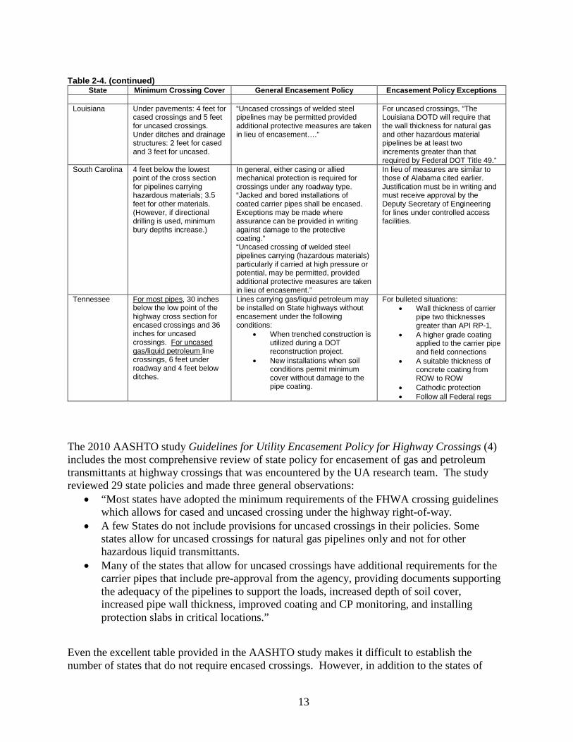
Table 2-4. (continued)
State Minimum Crossing Cover General Encasement Policy Encasement Policy Exceptions Louisiana Under pavements: 4 feet for
cased crossings and 5 feet for uncased crossings. Under ditches and drainage structures: 2 feet for cased and 3 feet for uncased.
“Uncased crossings of welded steel pipelines may be permitted provided additional protective measures are taken in lieu of encasement….”
For uncased crossings, “The Louisiana DOTD will require that the wall thickness for natural gas and other hazardous material pipelines be at least two increments greater than that required by Federal DOT Title 49.”
South Carolina 4 feet below the lowest point of the cross section for pipelines carrying hazardous materials; 3.5 feet for other materials. (However, if directional drilling is used, minimum bury depths increase.)
In general, either casing or allied mechanical protection is required for crossings under any roadway type. “Jacked and bored installations of coated carrier pipes shall be encased. Exceptions may be made where assurance can be provided in writing against damage to the protective coating.” “Uncased crossing of welded steel pipelines carrying (hazardous materials) particularly if carried at high pressure or potential, may be permitted, provided additional protective measures are taken in lieu of encasement.”
In lieu of measures are similar to those of Alabama cited earlier. Justification must be in writing and must receive approval by the Deputy Secretary of Engineering for lines under controlled access facilities.
Tennessee For most pipes, 30 inches below the low point of the highway cross section for encased crossings and 36 inches for uncased crossings. For uncased gas/liquid petroleum line crossings, 6 feet under roadway and 4 feet below ditches.
Lines carrying gas/liquid petroleum may be installed on State highways without encasement under the following conditions:
• When trenched construction is utilized during a DOT reconstruction project.
• New installations when soil conditions permit minimum cover without damage to the pipe coating.
For bulleted situations: • Wall thickness of carrier
pipe two thicknesses greater than API RP-1,
• A higher grade coating applied to the carrier pipe and field connections
• A suitable thickness of concrete coating from ROW to ROW
• Cathodic protection • Follow all Federal regs
The 2010 AASHTO study Guidelines for Utility Encasement Policy for Highway Crossings (4)
includes the most comprehensive review of state policy for encasement of gas and petroleum transmittants at highway crossings that was encountered by the UA research team. The study reviewed 29 state policies and made three general observations:
• “Most states have adopted the minimum requirements of the FHWA crossing guidelines which allows for cased and uncased crossing under the highway right-of-way.
• A few States do not include provisions for uncased crossings in their policies. Some states allow for uncased crossings for natural gas pipelines only and not for other hazardous liquid transmittants.
• Many of the states that allow for uncased crossings have additional requirements for the carrier pipes that include pre-approval from the agency, providing documents supporting the adequacy of the pipelines to support the loads, increased depth of soil cover, increased pipe wall thickness, improved coating and CP monitoring, and installing protection slabs in critical locations.”
Even the excellent table provided in the AASHTO study makes it difficult to establish the number of states that do not require encased crossings. However, in addition to the states of
14
Arkansas and Florida identified earlier, AASHTO seems to identify at least two other states that list conditions where encased crossings are not required (quotes are from the AASHTO study):
• Indiana: “May be encased or non-encased.” • Washington: “Casings shall not be required for pipelines carrying natural gas. Casing is
required for pressurized carrier pipes, other than natural gas.”
ALDOT minimum cover policies for pipelines in typical highway crossing situations currently require three feet of cover under sod ditches and 4 feet of cover under pavements where ditches are not involved (such as in curb and gutter areas). If this study’s recommendation that encasement of natural gas and hazardous liquid pipelines at roadway crossings no longer be required is accepted, the researchers recommend that minimum cover policies also be amended. The new recommendation is that minimum cover requirements become a minimum 48 inches under ditches or a minimum 60 inches from highway surface, whichever places the pipe facility deeper. Two pieces of information support this position:
• In Alabama, sign supports are placed at three feet depth and barrier rail posts are placed at four feet depth. The recommended minimum depth provides increased safety for pipelines near those facilities.
• ALDOT personnel are strongly concerned about the integrity of the roadway prism and damage from dig-ins when pipes are not shielded with casing. The recommended minimum depth provides increased safety from such dig-ins.
2.8 Local Policies Cities and towns in Alabama generally do not require encasement at road crossings. Tuscaloosa, for instance, has no specific regulation regarding pipeline road crossings, but the crossings must meet approval by the city engineer. Tuscaloosa does not generally require encasement. Similarly, Mobile has no requirements concerning encasement of natural gas and hazardous liquid material pipelines.
15
Chapter 3: Benefits and Drawbacks of Encasement 3.1 The Benefits of Encasement The following reasons have been cited for employing encasement at road crossings:
• The casing reduces the fatigue, overburden, and wheel loads on the pipe, • Casing allows for easy replacement of damaged pipes, • Casing reduces the risk of dig-ins, • Casing provides for detection of leaks, • Casing prevents coating damage during pipe installation, and • The dry environment in the casing prevents corrosion.
The following sections address these perceived benefits and show why several of them have not proven accurate in practice. Wheel loads and overburden stresses act to collapse the pipe, while internal pressures tend to burst the pipe. The two counteract each other to some extent. The worst case for collapse comes when the internal pressure is zero, and casing certainly reduces the collapse loads on the carrier pipe. However, even on construction sites with heavy equipment and off-road wheel loads, overburden stresses are actually quite small compared to typical burst loads from internal pressures, and ASME no longer includes collapse loads in design of gas pipe, either steel or plastic, rather depending on the thickness required for burst loading to support the collapse loading. Collapse loads are included for hazardous liquids pipelines by requiring the application of API 1102 at crossings, probably because internal pressures are generally low in hazardous liquids lines. Several recent state highway crossings of gas pipelines are uncased, and few of the crossings in Alabama cities and towns are cased, without apparent repercussions. The researchers’ analysis of PHMSA data on gas and hazardous material pipeline incidents found in Section 4.1 of this report does not indicate any instances of pipeline failure by collapse. Furthermore, casing is designed in the same way as carrier pipe. So, at a road crossing, the casing of a gas line, which carries no internal pressure, is designed only to withstand the collapse and fatigue loads, while the carrier pipe is designed to withstand the burst pressure, usually resulting in carrier pipe that is more robust than the casing. Replacement of damaged pipes at road crossings is usually managed by boring or drilling a new crossing rather than reusing the existing casing. Accessing the old casing and removing the old carrier pipe requires accurate excavation of a sizable work pit on both sides of the highway and pulling out and replacing the carrier pipe, which is substantially more demanding than installing a new crossing and abandoning the old pipe in-place. Casing may reduce the risk of dig-ins. Table 4 in Chapter 4 of this report shows hazardous liquid pipeline and natural gas pipeline incident data from PHMSA from 2010 to 2012 at road
16
crossings. From 2010 to 2012, there were 11 incidents at road crossings with cased pipe and 19 with uncased pipe. Of the uncased incidents, 10 were dig-ins, while no dig-ins occurred on cased pipe. Though the table represents a small data set, it does imply that encasement provides protection from dig-ins. However, uncased pipe in the right-of-way running longitudinally to the road is commonly allowed, and, because there is a far greater length of longitudinal pipe than crossing pipe on highway right-of-way, it may be a far greater risk for dig-ins than the crossings. Casing directly provides for detection of gas leaks only in the special case of vertical vent pipes with telltale flip-up caps on the top. These are not in use at Alabama state highway crossings, where the vents are open and pointing downward. The downward pointing vents could be checked with a gas sniffer, but this is not common practice. When there is no casing in place, gas leaks may sometimes be identified by a patch of dead grass or weeds over the leak site. Casing would prevent this occurring. Regardless, a gas leak from a pipeline at a crossing is equally likely to cause a highway shutdown for repair whether the crossing is cased or uncased. It should be noted that vent pipes do provide a visual indication of a pipe crossing but also cause an additional obstacle for maintenance operations such as mowing. Modern pipeline coatings are highly resistant to damage during installation. Immediately after installation and throughout the life of uncased pipelines, the coating integrity is checked by pipe to earth conductivity measurements, so that if the coating is damaged it can be detected quickly. This check works at any depth and underneath pavements for uncased pipe, but this simple check cannot be performed inside cased pipes. The environment in the casing does not prevent corrosion. Although casings are installed with seals at the ends, it is common to find old casings with the seals partially collapsed and leaking water into the casing. This water produces a corrosive environment that is further exacerbated if the pipe actually contacts the casing, which can happen when spacers around the carrier pipe do not perform as intended. Reports from NACE International (10) (see Section 3.2 of this report) and from the research team’s review of PHMSA data found in Section 4.1 indicate that corrosion problems are more likely in cased crossings than uncased crossings.
3.2 The Drawbacks to Encasement The following have been cited as drawbacks to encasement:
• Increased likelihood of corrosion • Increased difficulty and cost of inspection and maintenance • Increased cost of installation
The following sections address these drawbacks and provide examples to substantiate them. An increased likelihood of external corrosion is a primary drawback to encasement. Corrosion is a significant cause of failure in both natural gas and hazardous liquid pipelines, and according to many in the industry, the problem of corrosion is exacerbated by casings. NACE International (formerly the National Association of Corrosion Engineers) cautions against the use of casings. According to NACE International, there is little evidence that casings provide their
17
purported benefits (protection from dig-ins, protection from external loads, replacement of carrier pipe without disturbing the roadway), but there are conditions that can develop inside a casing that increase the likelihood of external corrosion (10). Furthermore, casings increase the difficulty of providing the carrier pipe with cathodic protection (10). NACE International experts assert that the benefits desired from casing can be achieved through other means, including a concrete coating for protection from third-party damage and additional cover (10). PHMSA has indicated that uncased crossings are preferred where feasible due to the lack of cathodic protection shielding issues and ease of maintenance (11). If uncased crossings are used, an increase in pipe wall thickness may be required based on Location Class (11). PHMSA recommends the design process detailed in API RP 1102 for welded steel pipelines carrying natural gas or hazardous liquids (11). PHMSA is preparing a letter to the ALDOT Chief Engineer that will contain the following language, “PHMSA recommends, where practicable, the installation of uncased pipeline highway crossings because uncased crossings: 1) require a heavier wall thickness (or stronger/higher grade) pipe, 2) reduces integrity and maintenance issues, and 3) avoids cathodic protection issues associated with cased pipes.” Inspection and maintenance is more difficult and costly to perform on cased pipes than uncased pipes. Casings make inspection more difficult because “conventional aboveground indirect inspection tools used in [direct assessment] are not effective if there is no electrical path to the structure, such as with cased pipelines (10).” This is more of an issue for gas pipelines than hazardous liquid lines, as hazardous liquid lines can be assessed by a pressure test or inline inspection. Existing methods of inspecting cased pipes have “practical limits as well as high cost (10).” If there is a problem with a carrier pipe within a casing, the casing is typically not reused, which significantly increases the cost of maintaining cased pipes. Cased pipe is more costly to install than uncased pipe. The AASHTO study (4) cites higher material, labor, equipment, and maintenance costs for cased crossings. The study provides a cost estimate comparing cased vs. uncased crossing for a 6-inch diameter, 300-foot long steel pipe based on 2008 Midwest cost estimates. The results indicate that “these costs may add up to be twice to three times the cost of installing a single carrier pipe (4).” UA researchers interviewed three Alabama utility contractors whose names had been supplied by the Alabama Utility Contractors Association. The contractors confirmed the increased costs for cased crossings but pointed out that the cost associated with a cased vs. an uncased crossing is highly dependent on site conditions and project requirements. Their general comments follow:
• By allowing uncased crossings, construction techniques such as horizontal directional drilling (HDD) become available, which in many situations is very economical.
• If the construction technique is constant, it can be expected that a cased crossing can cost twice as much as an uncased crossing.
• Installing only a carrier pipe at a crossing and allowing horizontal directional drilling, as opposed to requiring jack and bore and a cased crossing, a savings of 75 percent could be realized.
• Horizontal directional drilling becomes even more economical on longer crossings, greater than 200 feet, because jack and bore requires larger diameter casing pipes that are able to withstand the large jacking forces associated with long runs.
18
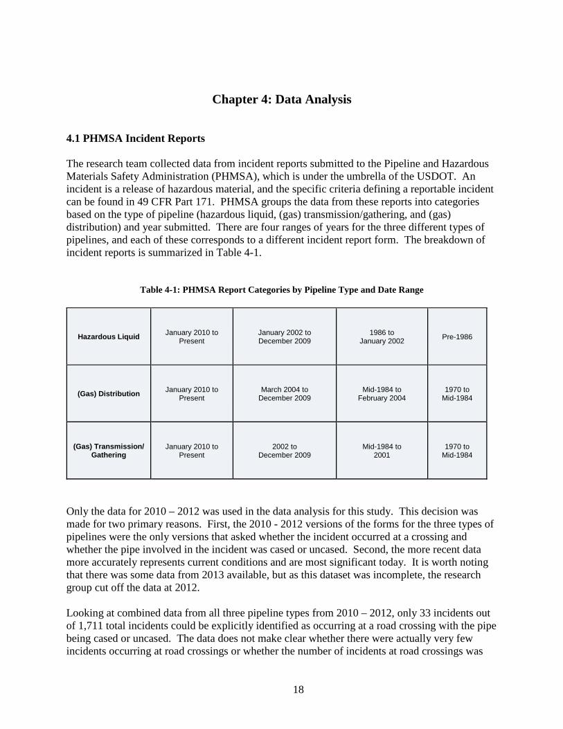
Chapter 4: Data Analysis 4.1 PHMSA Incident Reports The research team collected data from incident reports submitted to the Pipeline and Hazardous Materials Safety Administration (PHMSA), which is under the umbrella of the USDOT. An incident is a release of hazardous material, and the specific criteria defining a reportable incident can be found in 49 CFR Part 171. PHMSA groups the data from these reports into categories based on the type of pipeline (hazardous liquid, (gas) transmission/gathering, and (gas) distribution) and year submitted. There are four ranges of years for the three different types of pipelines, and each of these corresponds to a different incident report form. The breakdown of incident reports is summarized in Table 4-1.
Table 4-1: PHMSA Report Categories by Pipeline Type and Date Range
Hazardous Liquid January 2010 to Present
January 2002 to December 2009
1986 to January 2002 Pre-1986
(Gas) Distribution January 2010 to Present
March 2004 to December 2009
Mid-1984 to February 2004
1970 to Mid-1984
(Gas) Transmission/ Gathering
January 2010 to Present
2002 to December 2009
Mid-1984 to 2001
1970 to Mid-1984
Only the data for 2010 – 2012 was used in the data analysis for this study. This decision was made for two primary reasons. First, the 2010 - 2012 versions of the forms for the three types of pipelines were the only versions that asked whether the incident occurred at a crossing and whether the pipe involved in the incident was cased or uncased. Second, the more recent data more accurately represents current conditions and are most significant today. It is worth noting that there was some data from 2013 available, but as this dataset was incomplete, the research group cut off the data at 2012.
Looking at combined data from all three pipeline types from 2010 – 2012, only 33 incidents out of 1,711 total incidents could be explicitly identified as occurring at a road crossing with the pipe being cased or uncased. The data does not make clear whether there were actually very few incidents occurring at road crossings or whether the number of incidents at road crossings was
19
being underreported due to changes in the incident reporting form. According to the PHMSA data, 14 of the 1,711 pipeline incidents that occurred from 2010 - 2012 occurred in Alabama. None of these incidents occurred at road crossings. Because there were only 33 crossing incidents to analyze, the UA research team examined the remaining data to detect general trends in incidents of the type that could occur at crossings or near a roadway. For example, the team looked for broad trends in the number of incidents due to corrosion, excavation, material failure, etc. To reduce the 1,711 incidents to examine only the types of incidents that could have occurred at crossings, the data was subjected to a culling process. Pipes located above ground, under water, or under buildings were eliminated, as well as incidents associated with appurtenances that would not be found at a road crossing (valves, stopples, sumps, etc.). The culling process reduced the total incidents from 1,711 to 476, a 72.2% reduction. The 476 represent incidents both at highway crossings and not at highway crossings; however, because the large majority of the 476 were not identified as being at crossings, the research team inferred that most of these incidents represent uncased pipes.
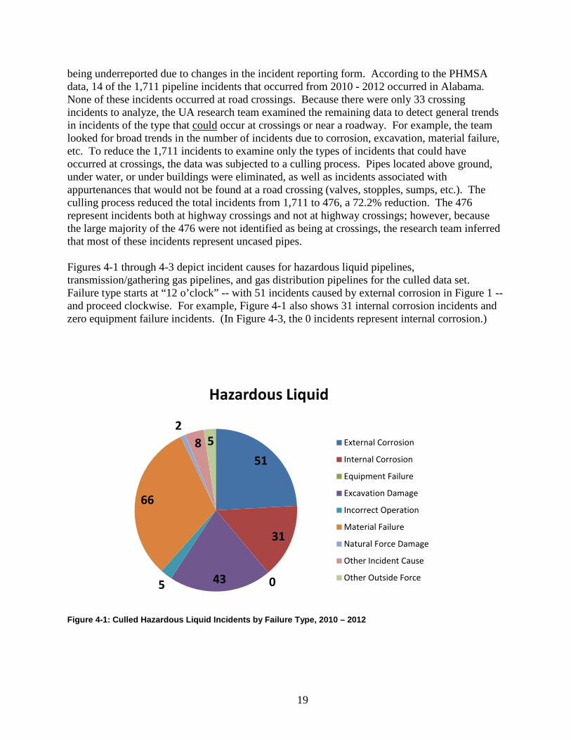
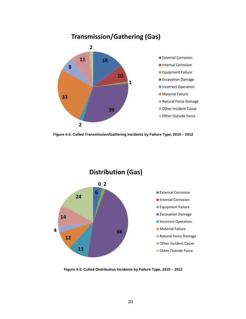
Figures 4-1 through 4-3 depict incident causes for hazardous liquid pipelines, transmission/gathering gas pipelines, and gas distribution pipelines for the culled data set. Failure type starts at “12 o’clock” -- with 51 incidents caused by external corrosion in Figure 1 -- and proceed clockwise. For example, Figure 4-1 also shows 31 internal corrosion incidents and zero equipment failure incidents. (In Figure 4-3, the 0 incidents represent internal corrosion.)
Figure 4-1: Culled Hazardous Liquid Incidents by Failure Type, 2010 – 2012
51
31
0435
66
28 5
Hazardous Liquid
External Corrosion
Internal Corrosion
Equipment Failure
Excavation Damage
Incorrect Operation
Material Failure
Natural Force Damage
Other Incident Cause
Other Outside Force
20
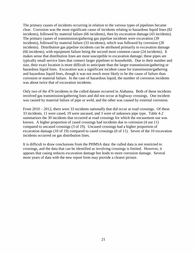
Figure 4-2: Culled Transmission/Gathering Incidents by Failure Type, 2010 – 2012
Figure 4-3: Culled Distribution Incidents by Failure Type, 2010 – 2012
18
101
39
2
33
811
2
Transmission/Gathering (Gas)
External Corrosion
Internal Corrosion
Equipment Failure
Excavation Damage
Incorrect Operation
Material Failure
Natural Force Damage
Other Incident Cause
Other Outside Force
60 2
66
13
124
14
24
Distribution (Gas)
External Corrosion
Internal Corrosion
Equipment Failure
Excavation Damage
Incorrect Operation
Material Failure
Natural Force Damage
Other Incident Cause
Other Outside Force
21
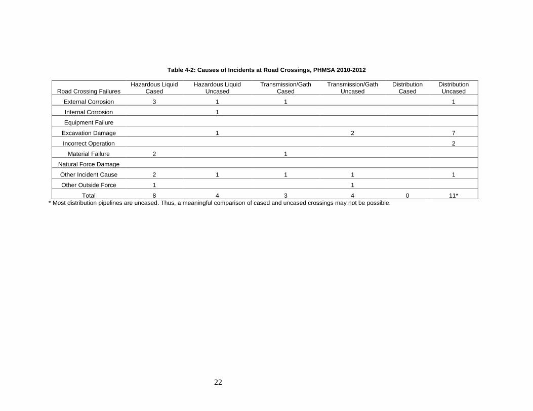
The primary causes of incidents occurring in relation to the various types of pipelines became clear. Corrosion was the most significant cause of incidents relating to hazardous liquid lines (82 incidents), followed by material failure (66 incidents), then by excavation damage (43 incidents). The primary causes of transmission/gathering gas pipeline incidents were excavation (39 incidents), followed by material failure (33 incidents), which was followed by corrosion (28 incidents). Distribution gas pipeline incidents can be attributed primarily to excavation damage (66 incidents), with equipment failure being the second most common cause (24 incidents). It makes sense that distribution lines are most susceptible to excavation damage; these pipes are typically small service lines that connect larger pipelines to households. Due to their number and size, their exact location is more difficult to anticipate than the larger transmission/gathering or hazardous liquid lines. Excavation was a significant incident cause for transmission/gathering and hazardous liquid lines, though it was not much more likely to be the cause of failure than corrosion or material failure. In the case of hazardous liquid, the number of corrosion incidents was about twice that of excavation incidents. Only two of the 476 incidents in the culled dataset occurred in Alabama. Both of these incidents involved gas transmission/gathering lines and did not occur at highway crossings. One incident was caused by material failure of pipe or weld, and the other was caused by external corrosion. From 2010 – 2012, there were 33 incidents nationally that did occur at road crossings. Of these 33 incidents, 11 were cased, 19 were uncased, and 3 were of unknown pipe type. Table 4-2 summarizes the 30 incidents that occurred at road crossings for which the encasement use was known. A higher proportion of cased crossings had incidents due to corrosion (4 out 11) compared to uncased crossings (3 of 19). Uncased crossings had a higher proportion of excavation damage (10 of 19) compared to cased crossings (0 of 11). Seven of the 10 excavation incidents occurred on gas distribution lines. It is difficult to draw conclusions from the PHMSA data: the culled data is not restricted to crossings, and the data that can be identified as involving crossings is limited. However, it appears that casing reduces excavation damage but leads to more corrosion damage. Several more years of data with the new report form may provide a clearer picture.
22
Table 4-2: Causes of Incidents at Road Crossings, PHMSA 2010-2012
Road Crossing Failures Hazardous Liquid
Cased Hazardous Liquid
Uncased Transmission/Gath
Cased Transmission/Gath
Uncased Distribution
Cased Distribution Uncased
External Corrosion 3 1 1 1
Internal Corrosion 1
Equipment Failure
Excavation Damage 1 2 7
Incorrect Operation 2
Material Failure 2 1
Natural Force Damage
Other Incident Cause 2 1 1 1 1
Other Outside Force 1 1
Total 8 4 3 4 0 11* * Most distribution pipelines are uncased. Thus, a meaningful comparison of cased and uncased crossings may not be possible.
23
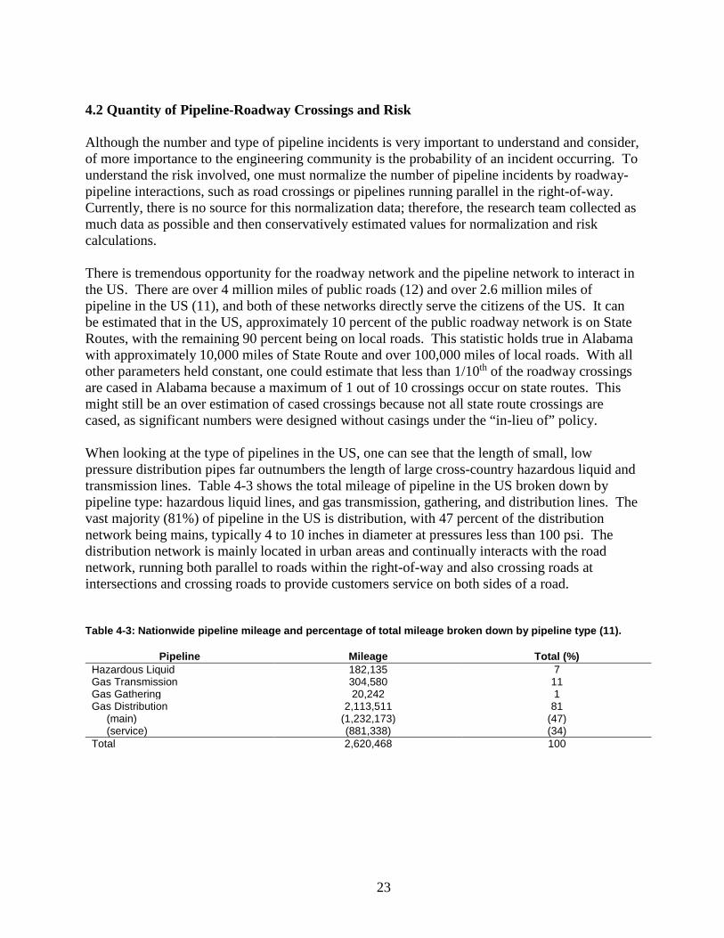
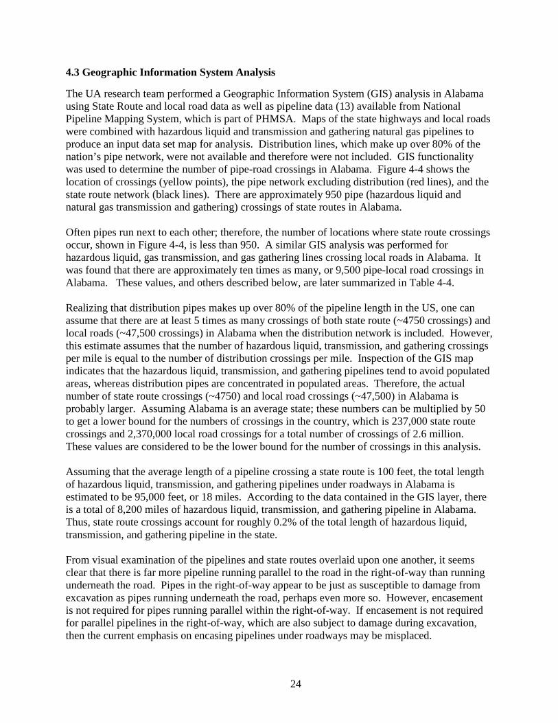
4.2 Quantity of Pipeline-Roadway Crossings and Risk Although the number and type of pipeline incidents is very important to understand and consider, of more importance to the engineering community is the probability of an incident occurring. To understand the risk involved, one must normalize the number of pipeline incidents by roadway-pipeline interactions, such as road crossings or pipelines running parallel in the right-of-way. Currently, there is no source for this normalization data; therefore, the research team collected as much data as possible and then conservatively estimated values for normalization and risk calculations. There is tremendous opportunity for the roadway network and the pipeline network to interact in the US. There are over 4 million miles of public roads (12) and over 2.6 million miles of pipeline in the US (11), and both of these networks directly serve the citizens of the US. It can be estimated that in the US, approximately 10 percent of the public roadway network is on State Routes, with the remaining 90 percent being on local roads. This statistic holds true in Alabama with approximately 10,000 miles of State Route and over 100,000 miles of local roads. With all other parameters held constant, one could estimate that less than 1/10th of the roadway crossings are cased in Alabama because a maximum of 1 out of 10 crossings occur on state routes. This might still be an over estimation of cased crossings because not all state route crossings are cased, as significant numbers were designed without casings under the “in-lieu of” policy. When looking at the type of pipelines in the US, one can see that the length of small, low pressure distribution pipes far outnumbers the length of large cross-country hazardous liquid and transmission lines. Table 4-3 shows the total mileage of pipeline in the US broken down by pipeline type: hazardous liquid lines, and gas transmission, gathering, and distribution lines. The vast majority (81%) of pipeline in the US is distribution, with 47 percent of the distribution network being mains, typically 4 to 10 inches in diameter at pressures less than 100 psi. The distribution network is mainly located in urban areas and continually interacts with the road network, running both parallel to roads within the right-of-way and also crossing roads at intersections and crossing roads to provide customers service on both sides of a road.
Table 4-3: Nationwide pipeline mileage and percentage of total mileage broken down by pipeline type (11).
Pipeline Mileage Total (%) Hazardous Liquid 182,135 7 Gas Transmission 304,580 11 Gas Gathering 20,242 1 Gas Distribution 2,113,511 81 (main) (1,232,173) (47) (service) (881,338) (34) Total 2,620,468 100
24
4.3 Geographic Information System Analysis
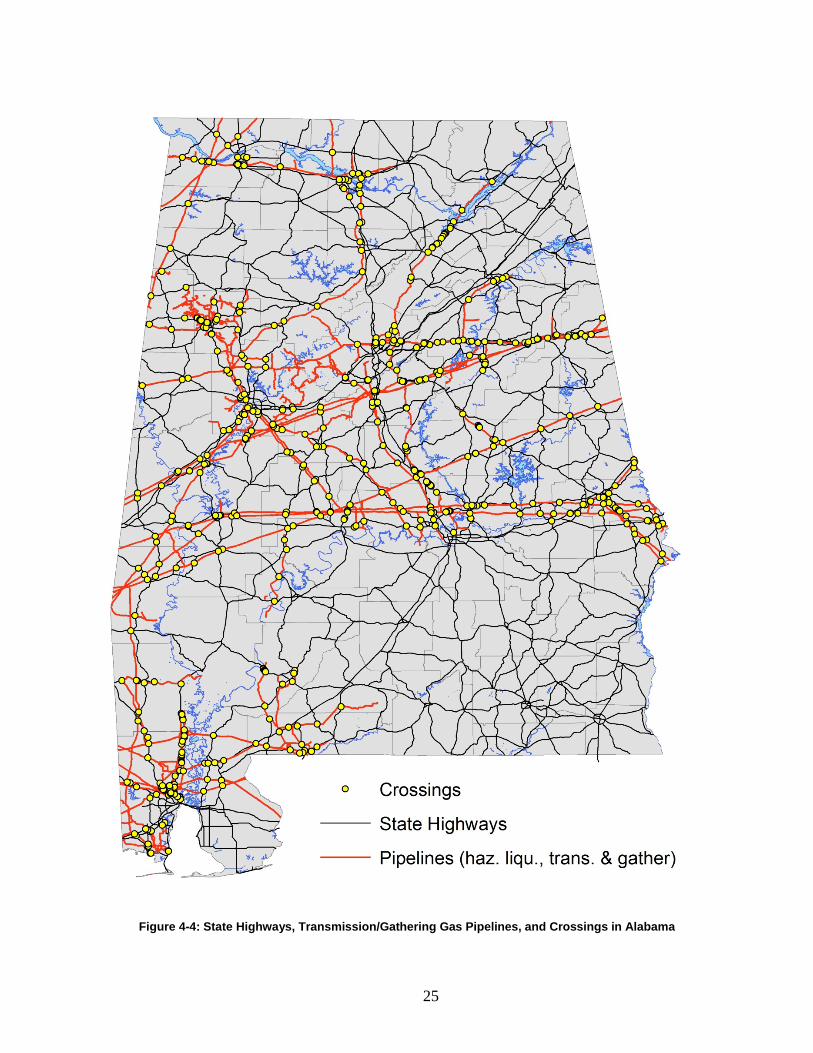
The UA research team performed a Geographic Information System (GIS) analysis in Alabama using State Route and local road data as well as pipeline data (13) available from National Pipeline Mapping System, which is part of PHMSA. Maps of the state highways and local roads were combined with hazardous liquid and transmission and gathering natural gas pipelines to produce an input data set map for analysis. Distribution lines, which make up over 80% of the nation’s pipe network, were not available and therefore were not included. GIS functionality was used to determine the number of pipe-road crossings in Alabama. Figure 4-4 shows the location of crossings (yellow points), the pipe network excluding distribution (red lines), and the state route network (black lines). There are approximately 950 pipe (hazardous liquid and natural gas transmission and gathering) crossings of state routes in Alabama. Often pipes run next to each other; therefore, the number of locations where state route crossings occur, shown in Figure 4-4, is less than 950. A similar GIS analysis was performed for hazardous liquid, gas transmission, and gas gathering lines crossing local roads in Alabama. It was found that there are approximately ten times as many, or 9,500 pipe-local road crossings in Alabama. These values, and others described below, are later summarized in Table 4-4. Realizing that distribution pipes makes up over 80% of the pipeline length in the US, one can assume that there are at least 5 times as many crossings of both state route (~4750 crossings) and local roads (~47,500 crossings) in Alabama when the distribution network is included. However, this estimate assumes that the number of hazardous liquid, transmission, and gathering crossings per mile is equal to the number of distribution crossings per mile. Inspection of the GIS map indicates that the hazardous liquid, transmission, and gathering pipelines tend to avoid populated areas, whereas distribution pipes are concentrated in populated areas. Therefore, the actual number of state route crossings (~4750) and local road crossings (~47,500) in Alabama is probably larger. Assuming Alabama is an average state; these numbers can be multiplied by 50 to get a lower bound for the numbers of crossings in the country, which is 237,000 state route crossings and 2,370,000 local road crossings for a total number of crossings of 2.6 million. These values are considered to be the lower bound for the number of crossings in this analysis. Assuming that the average length of a pipeline crossing a state route is 100 feet, the total length of hazardous liquid, transmission, and gathering pipelines under roadways in Alabama is estimated to be 95,000 feet, or 18 miles. According to the data contained in the GIS layer, there is a total of 8,200 miles of hazardous liquid, transmission, and gathering pipeline in Alabama. Thus, state route crossings account for roughly 0.2% of the total length of hazardous liquid, transmission, and gathering pipeline in the state. From visual examination of the pipelines and state routes overlaid upon one another, it seems clear that there is far more pipeline running parallel to the road in the right-of-way than running underneath the road. Pipes in the right-of-way appear to be just as susceptible to damage from excavation as pipes running underneath the road, perhaps even more so. However, encasement is not required for pipes running parallel within the right-of-way. If encasement is not required for parallel pipelines in the right-of-way, which are also subject to damage during excavation, then the current emphasis on encasing pipelines under roadways may be misplaced.
25
Figure 4-4: State Highways, Transmission/Gathering Gas Pipelines, and Crossings in Alabama
26
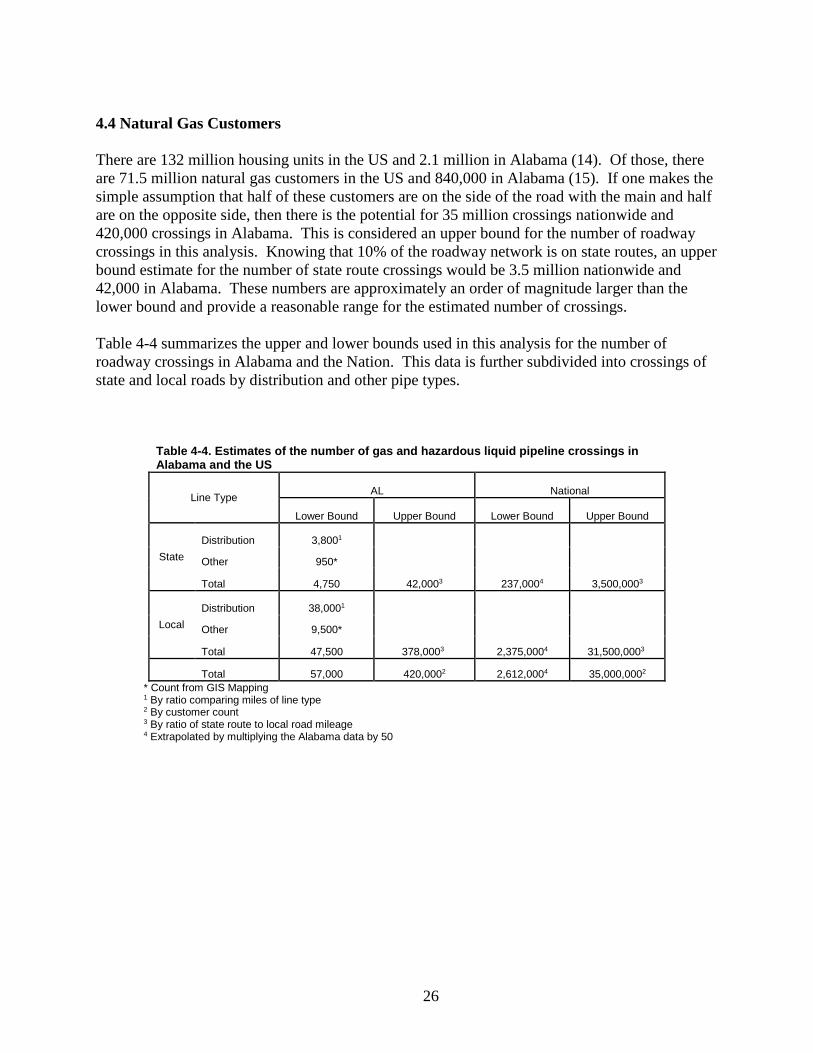
4.4 Natural Gas Customers There are 132 million housing units in the US and 2.1 million in Alabama (14). Of those, there are 71.5 million natural gas customers in the US and 840,000 in Alabama (15). If one makes the simple assumption that half of these customers are on the side of the road with the main and half are on the opposite side, then there is the potential for 35 million crossings nationwide and 420,000 crossings in Alabama. This is considered an upper bound for the number of roadway crossings in this analysis. Knowing that 10% of the roadway network is on state routes, an upper bound estimate for the number of state route crossings would be 3.5 million nationwide and 42,000 in Alabama. These numbers are approximately an order of magnitude larger than the lower bound and provide a reasonable range for the estimated number of crossings. Table 4-4 summarizes the upper and lower bounds used in this analysis for the number of roadway crossings in Alabama and the Nation. This data is further subdivided into crossings of state and local roads by distribution and other pipe types.
Table 4-4. Estimates of the number of gas and hazardous liquid pipeline crossings in Alabama and the US
Line Type AL National
Lower Bound Upper Bound Lower Bound Upper Bound
State Distribution 3,8001
Other 950*
Total 4,750 42,0003 237,0004 3,500,0003
Local Distribution 38,0001
Other 9,500*
Total 47,500 378,0003 2,375,0004 31,500,0003
Total 57,000 420,0002 2,612,0004 35,000,0002 * Count from GIS Mapping 1 By ratio comparing miles of line type 2 By customer count 3 By ratio of state route to local road mileage 4 Extrapolated by multiplying the Alabama data by 50
27
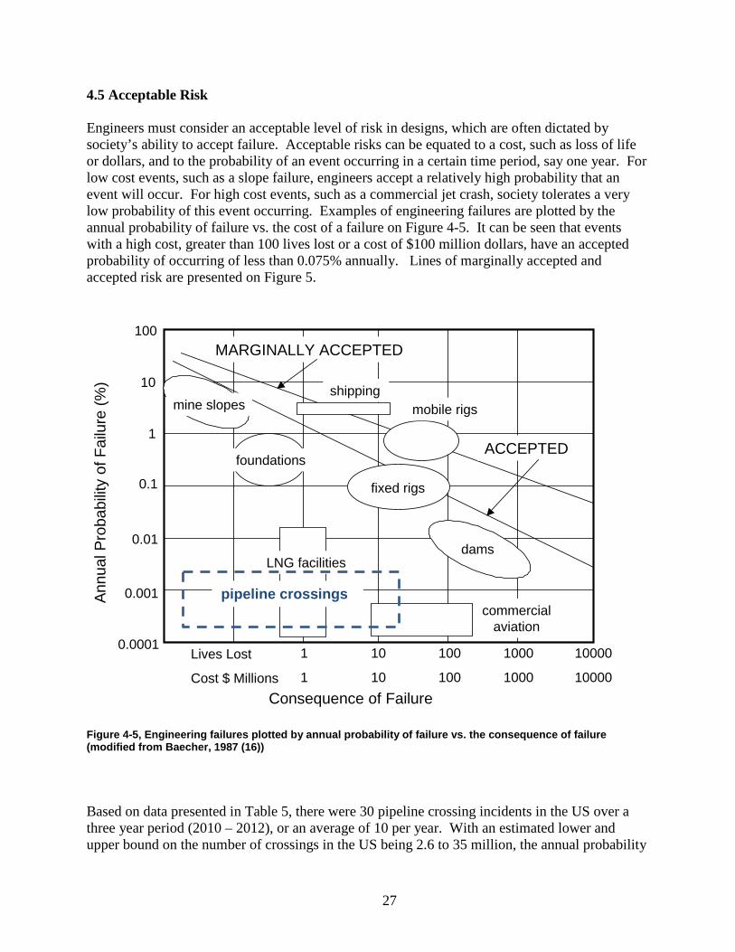
4.5 Acceptable Risk Engineers must consider an acceptable level of risk in designs, which are often dictated by society’s ability to accept failure. Acceptable risks can be equated to a cost, such as loss of life or dollars, and to the probability of an event occurring in a certain time period, say one year. For low cost events, such as a slope failure, engineers accept a relatively high probability that an event will occur. For high cost events, such as a commercial jet crash, society tolerates a very low probability of this event occurring. Examples of engineering failures are plotted by the annual probability of failure vs. the cost of a failure on Figure 4-5. It can be seen that events with a high cost, greater than 100 lives lost or a cost of $100 million dollars, have an accepted probability of occurring of less than 0.075% annually. Lines of marginally accepted and accepted risk are presented on Figure 5.
Figure 4-5, Engineering failures plotted by annual probability of failure vs. the consequence of failure (modified from Baecher, 1987 (16))
Based on data presented in Table 5, there were 30 pipeline crossing incidents in the US over a three year period (2010 – 2012), or an average of 10 per year. With an estimated lower and upper bound on the number of crossings in the US being 2.6 to 35 million, the annual probability
MARGINALLY ACCEPTED
ACCEPTED
mine slopes
foundations
dams
mobile rigs
commercialaviation
LNG facilities
fixed rigs
shipping
1
1
10
10
100
100
1000
1000
10000
10000
100
10
1
0.1
0.01
0.001
0.0001
Annu
al P
roba
bilit
y of
Fai
lure
(%)
Consequence of Failure
Lives Lost
Cost $ Millions
pipeline crossings
28
of failure at a crossing is 0.004% to 0.0003%. Assuming that the cost of an incident might be between $20 K and $20 M, pipeline roadway crossing incidents can be plotted on Figure 4-5. The dashed box on Figure 4-5 shows the annual probability of a pipeline crossing incident plotted against the consequence of failure. It can be seen that pipeline crossings are performing at least 2 orders of magnitude better than the acceptable level of risk. It should be noted that the vast majority, perhaps greater than 90%, of the pipeline crossings in the US that are performing so well are uncased crossings because the analysis above considered local roads and state routes as well as hazardous liquid, and gas transmission, gathering, and distribution pipelines.
29
Chapter 5: Software The UA researchers examined several pipeline design software packages and evaluated their suitability based on required functionality and cost. Robust software packages that contained extensive functionality tended to be expensive. Because ALDOT’s primary purpose for a software package is to check pipeline designs to ensure a sufficient factor of safety, many of the programs included functionality not necessary for ALDOT’s purposes, including GIS-based spatial representation of networks, modeling capability, asset management, and analysis tools for network components other than pipes. Some of the packages that were investigated included software from Quorum Business Solutions, Inc., New Century Software, GL Noble Denton, Energy Solutions International, PROCAD Software, and Bentley. One commercial software that appears to meet ALDOT’s needs is Pipeline Toolbox – Gas published by Technical Toolboxes. This software is based on ASME B31.8, and it includes “PC-Pisces/Wheel & Track Load Calculations.” These calculations should be similar (if not identical) to the calculations that are being used by ALDOT to check variances. This software package costs $995/per user/per year. The research group evaluated this software, and it is able to perform the types of calculations required by ALDOT. However, one shortcoming of the software is that the calculations are not transparent. The user inputs the design, and the program indicates whether the design passed or failed four different checks. It does not clearly display how it determined whether the design passed or failed these checks. It also does not indicate the factor of safety that was applied.
To better understand the results offered by Pipeline Toolbox, UA’s Dr. Philip Johnson programmed a spreadsheet based on API RP 1102. The spreadsheet is very similar to the well-known but no longer available PC-Pisces software, and it produces results almost identical to Pipeline Toolbox. The spreadsheet is a much more transparent program in that the user can see the safety factor (also called the design factor) and have a better idea of how it is determined. The software is currently in the alpha version, and it would need to undergo a thorough testing process before it could be used to check pipe designs. Figure 5-1 shows a screenshot of the spreadsheet.
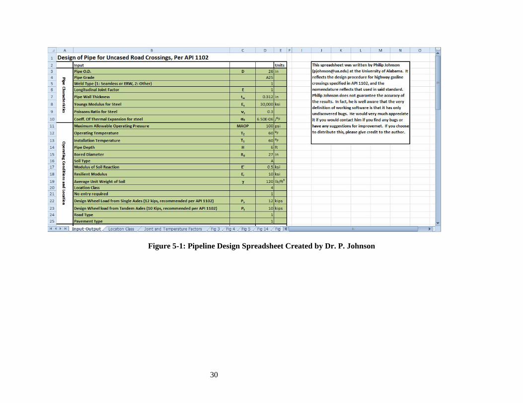
30
Figure 5-1: Pipeline Design Spreadsheet Created by Dr. P. Johnson
31
Chapter 6: Conclusions It is the recommendation of the University of Alabama researchers that ALDOT follow CFR Title 49 Volume 3 Part 192 for natural gas pipeline design and CFR Title 49 Volume 3 Part 195 for hazardous liquid pipeline design and that the encasement of natural gas and hazardous liquid pipelines at ALDOT highway crossings should not be required, except for special situations already cited in the ALDOT Utilities Manual such as instances of insufficient cover or near footings of bridges. The principal reasons for this finding are listed below:
• PHMSA recommends, where practicable to install, uncased natural gas and hazardous liquid pipeline highway crossings because uncased crossings: 1) may require a heavier wall thickness pipe based on Location Class, 2) reduce maintenance issues, and 3) avoid cathodic protection shielding issues associated with cased pipes.
• ASME B31.4 states that uncased crossings are “preferred” for hazardous liquid pipelines. • NACE, the National Association of Corrosion Engineers recommends against casing and
cites other alternatives in situations where extra strength might be desired. • Though costs vary by installation, a cased crossing may typically cost twice as much as
an equivalent uncased crossing • Many of the perceived benefits of casings have not been proven in service. For example,
ASME/ANSI standards no longer include collapse losses in design of gas pipelines; instead, they depend on the thickness required for burst loading. At the same time, casing can lead to an increased likelihood of corrosion, a higher cost in installation and maintenance, and a greater level of difficulty in performing maintenance.
• Allowing uncased highway crossings will place ALDOT in agreement with the practices of most cities in Alabama.
• An analysis of natural gas transmission and gathering lines using GIS indicates that there is significantly more pipeline running parallel to the road in the right-of-way than running underneath the road, and encasement is not required for this longitudinal pipe. If encasement is not required for longitudinal pipelines in the right-of-way, which are also subject to damage during excavation, then the current emphasis on encasing pipelines under roadways may be misplaced.
• A risk analysis showed that for gas and hazardous material pipeline crossings the level of risk appears to be at least 2 orders of magnitude better than the acceptable level of risk. Because the large majority of these crossings are uncased, then uncased crossings are also performing to this standard.
Analysis of PHMSA incident data for roadway crossings does show a higher proportion of excavation (dig-in) incidents for uncased pipe than for cased pipe. However, that analysis also indicates that cased crossings lead to more corrosion damage. Based on these findings, the researchers recommend that the requirement for encasement of natural gas and hazardous liquid pipelines be removed from the Alabama Utilities Manual and be replaced with a requirement to follow CFR Title 49 Volume 3 Part 192 for natural gas pipeline design and CFR Title 49 Volume 3 Part 195 for hazardous liquid pipeline design, both
32
of which incorporate other relevant standards by reference. Appendix A shows recommended revisions to the ALDOT Utilities Manual to reflect these findings. Separate reviews of state encasement policies performed for this project and in 2010 for a similar AASHTO study covered a total of 30 states. Of those states, four states – Arkansas, Florida, Indiana, and Washington – allow uncased crossings without requiring an approved variance request supported by special documentation. (Washington requires encasement for hazardous materials pipelines but not for natural gas pipelines). Thus, the recommendations of this report are in place in only four of 30 states reviewed. The ALDOT Utilities Manual minimum cover policies for pipelines in typical highway crossing situations currently require three feet of cover under sod ditches and 4 feet of cover under pavements where ditches are not involved (such as in curb and gutter areas). If this study’s recommendation that encasement of natural gas and hazardous liquid pipelines at roadway crossings no longer be required is accepted, the researchers recommend that minimum cover policies also be amended. The new recommendation is that minimum cover requirements become a minimum 48 inches under ditches or a minimum 60 inches from the highway surface, whichever places the pipe facility deeper. The new recommendation is made to protect the pipeline from damage from sign support and barrier rail post installation and to provide further measures to protect the integrity of the roadway prism. The researchers also evaluated several pipeline design software packages that ALDOT could use to check pipeline designs to ensure a sufficient factor of safety. They identified Pipeline Toolbox -- Gas published by Technical Toolboxes as one package that can meet ALDOT’s needs. As an additional aid in this area, UA’s Dr. Philip Johnson programmed a spreadsheet based on API RP 1102 and offered it as a potential alternative to commercial software after it undergoes verification testing.
33
References
1. “Protecting Pipelines at Crossings: Are Casings Obsolete?” Pipeline & Gas Journal, Vol. 236, No. 3, March 2009. 2. Alabama Department of Transportation. ALDOT Utilities Manual § 2.20.3 – 2.20.4
3. Alabama Department of Transportation. ALDOT Utilities Manual § 2.9.1 4. Farrag, K. “Guidelines for Utility Encasement Policy for Highway Crossings.” AASHTO Standing Committee on Highways. Project 20-07, Task 248 NCHRP. February 2010. 5. Stewart, H. E., O’Rourke, T. D., Ingraffea, A. R., Barry, A., Behn, M. T., Crossley, C. W., & El-Gharbawy, S. L. (1991). Guidelines for pipelines crossing highways (GRI-91/0284). Ithaca, NY: School of Civil and Environmental Engineering, Cornell University. 6. Federal Highway Administration, Program Guide: Utility Relocation and Accommodation on Federal-Aid Highway Projects, FHWA-IF-03-014, 2003. 7. American Association of State Highway and Transportation Officials, A Guide for Accommodating Utilities within Highway Right-of-Way, 2005. 8. Washington Administrative Code 478–136–030 9. INDOT Utility Accommodation Policy, Indiana Department of Transportation, Indianapolis, IN, July 30, 2013. 10. "Protecting Pipelines at Crossings: Are Casings Obsolete?" Pipeline & Gas Journal 236.3, 2009. 11. Nanney, Steve. “Highway Crossings – Cased or Uncased?” 2013 AASHTO Subcommittee on Right of Way, Utilities & Outdoor Advertising Controls Conference. Hyatt Regency, Savannah, GA. 16 April 2013. Conference Presentation. 12. Bureau of Transportation Statistics (2013) Unites states Department of Transportation, U.S. Public Road and Street Mileage by Functional System http://www.rita.dot.gov/bts/sites/rita.dot.gov.bts/files/publications/national_transportation_statistics/html/table_01_05.html 13. NPMS (2013), National Pipeline Mapping System, Pipeline and Hazardous Materials Safety Administration, https://www.npms.phmsa.dot.gov/
14. Unites States Census Bureau (2013) State and County Quick Facts, http://quickfacts.census.gov/qfd/states/01000.html
34
15. US Energy Information Administration (2013) Number of Natural Gas Consumers, http://www.eia.gov/dnav/ng/ng_cons_num_dcu_nus_a.htm 16. Baecher, G. B., 1987, Geotechnical Risk Analysis User’s Guide, FHWA/RD-87-011, Fed.
Hwy. Admin., McLean, 55p.
35
Appendix A – Recommended Changes to the ALDOT Utilities Manual This Appendix excerpts portions of Sections 2.9, 2.20, and 2.28 of the Alabama Utilities Accommodation Manual. It shows suggested changes to those sections to implement the encasement recommendations made in this report. Recommended deletions from the existing manual are shown as strikethroughs. Recommended additional language is italicized. The sections of the manual are not shown in their entirety; only portions to which recommended changes apply are included. 2.9.1 Industry Codes and Standards Utility installations on, over, or under the ROW of state highways and the utility attachments to highway structures will (as a minimum) be of durable materials designed for long service life expectancy and minimum need for routine service and maintenance. Installations will meet the following requirements: 1. Electric power and communication facilities will conform with the current applicable National Electrical Safety Code 2.Water lines will conform with the currently applicable specifications of the American Water Works Association 3.Pressure pipe lines will conform with the currently applicable sections of American National Standards Institute (ANSI), Standard Code for Pressure Piping; Title 49 CFR, parts 192, 193, and 195; and applicable industry codes 4.Liquid petroleum pipelines will conform with the currently applicable recommended practice of the American Petroleum Institute for Pipeline Crossings under Railroads and Highways 5.Any pipeline carrying hazardous materials will conform to the rules and regulations of the U. S. Department of Transportation governing the transportation of such materials . . . . . 2.20.2 Bury Cover of Pipelines The critical controls of bury cover on a pipeline crossing are the low points in the highway cross-section. Usually these are the bottoms of the longitudinal ditches as shown on figure 2-2. In establishing the depth of bury cover below an unpaved ditch, consideration will be given to potential increases in ditch depth from scour, ditch maintenance operations, or the need to increase the capacity of the ditch. On longitudinal installations the critical controls for bury cover are usually the depths of lateral drainage facilities, landscaping, buried utility lines, bridge
36
structures, and likely highway maintenance operations. The minimum required bury cover of pipelines within the highway right of way are explained in the following paragraphs. Under Ditches The minimum bury cover under sod ditches will be 1 meter. A lesser bury cover depth may be considered under paved ditches on a project by project basis. Under Pavement Where ditches are not involved, such as on curb and gutter sections, the minimum required bury cover under pavement for new or relocated installations will be 1.2 meters.
Other Situations
The minimum bury cover for utility installation within the ROW in other situations will be 1 meter on all types of highways. When installations must pass beneath highway drainage facilities, clearances will be approved on a project by project basis depending on the type of utility involved.
Minimum Bury Cover Not Possible
Where less than minimum prescribed bury cover is necessary because of other utilities, water table, ordinances, or similar reasons, the pipe will be protected with a casing or concrete slab not in contact with the pipeline, or other suitable measures acceptable to the Department will be used. Where less than minimum prescribed bury cover is desired, a variance must be filed and the utility bears the responsibility of justifying that minimum bury cover cannot be obtained and of supplying the Department with sufficient documentation to verify the pertinent circumstances in support of the request.
Hazardous Transmittants
Cover for pipelines carrying transmittants which are flammable, corrosive, expansive, energized, or unstable will not be granted a variance for the minimum prescribed bury cover outlined in these standards. National And Local Codes
37
The utility will not place a facility with less than the minimum bury cover required by national, state, local, or other applicable industrial codes governing the particular type of transmittant. A partial list of accepted industrial codes may be found in § 2.9 and chapter 5 of this manual. . . . . . 2.20.3 Encasement The Department requires the encasement of all utility facilities placed under the highway unless otherwise exempted within this manual, or unless a utility obtains approval to forego encasement. The encasement maximizes safety of traffic and structural integrity of the highway. Where a utility desires to place a facility under the highway prism without encasement, it must file a variance request. The Department places the burden of proof on the utility if it contends that encasement is unnecessary. The following controls are provided for encasement of pipeline crossings of the highway. Exemptions Natural gas pipelines and hazardous liquid pipelines are exempt from the general encasement requirement. However, encasement for these pipelines may be required by the Department (1) for any pipeline with less than minimum bury, (2) near footings of bridges or other highway structures or across unstable or subsiding ground, or (3) near other locations where there may be a hazard. Where Required Casings may be required for the following conditions and in other instances when indicated by the Department: If expedient for the insertion, removal, replacement, or maintenance of carrier pipe crossings of freeways, expressways, and other controlled access highways, and at other locations where it is necessary in order to avoid open-trenched construction As protection for carrier pipe from external loads or shock either during or after construction of the highway As a means of conveying leaking fluids away from the area directly beneath the traveled way to a point of venting at or near the ROW line, or to a point of drainage in the highway ditch or a natural drainage way Encasement or other suitable protection may also be required for any pipeline (1) with less than minimum bury, (2) near footings of bridges or other highway structures or across unstable or subsiding ground, or (3) near other locations where there may be hazard.
38
Transmittants to be Encased Except for exempted pipeline types, Where the utility cannot give satisfactory assurance to the Department that the highway user and the highway structure are adequately protected without the use of encasement, casing will be required for (1) pressurized carrier pipes crossing under major highways, and (2) carriers of transmittants which are flammable, corrosive, expansive, energized, or unstable, particularly if carried at high pressure or potential. Joint Use of Encasements The Department encourages joint use of a single encasement pipe where right of way is limited and utility relocation costs are extraordinary. The utility companies involved shall contact the Utility Engineer, for review and approval prior to beginning design work, where a joint use encasement is being considered. Under normal circumstances, two different utilities will not be allowed to place their pipeline in a single encasement. Coated Pipe If coated pipe is used for jacking or boring, the same pipe may not be used for a carrier pipe unless a method is devised to ensure that there is no damage to the pipe coatings. Pavement Support Rigid encasement or suitable bridging will be used where support of pavement would be impaired by depression of flexible carrier pipe. Figure 2-3 illustrates this process. Structural Design Casings will be designed to support the load of the highway plus any superimposed loads. They will equal or exceed the structural requirements for highway drainage facilities. Casings should be composed of materials of satisfactory durability for conditions to which they may be exposed. Length of Encasement Where encasements are used they will (where practical) extend (1) as far from the toe of the fill slope as the depth of the pit required to install or maintain the encasement and pipeline or (2) back of the ditch far enough to allow the ditch to function as a drain while the pit is open for the installation of the encasement and carrier pipe or (3) far enough to pull the carrier pipe and prevent water from the ditch from getting into the encasement or subgrade of the highway during construction or maintenance operation. On curbed sections encasement will extend outside the outer curb to a point far enough that the face of the pit (to install or maintain the encasement or pipe) will not be closer than 2 meters from the face of curb. Where appropriate, the encasement will extend to the access control line, to the outside of frontage roads, or to an indicated line that allows for future widening of the highway. Seal
39
Casing pipe will be sealed at the ends with an approved flexible material to prevent flowing water and debris from entering the annular space between the casing and the carrier. Appurtenances The installation will include necessary appurtenances such as vents and markers. Where possible on crossings the vents will be located at the ROW line so that they serve as markers for the pipeline crossing of the highway. See figure 2-2. 2.20.4 Allied Mechanical Protection for Encasement For a few situations, pipeline crossings may be installed without encasement. Normally such an installation is limited to open-trenched construction and service lines with inside diameter less than or equal to 50 mm. Examples of encasement and allied mechanical protection are shown on figure 2-4. The guidance in the following paragraphs applies when providing allied mechanical protection to uncased pipeline crossings of the highway. As specified in Section 2.20.3, natural gas pipelines and hazardous liquid pipelines are exempt from the general encasement requirement. Carrier Pipe Design On uncased construction, the carrier pipe will conform to the material and design requirements of appropriate utility industry and governmental codes and specifications. In addition, the carrier pipe will be designed to support the load of the highway plus any superimposed loads when the pipe is operated under all of its intended ranges of pressure. The installation will employ a higher factor of safety in the design, construction, and testing than normally would be required for cased construction. On new installations, or for retention of existing utility facilities under proposed highway construction, the utility's engineer, in accordance with the provisions of the state laws and regulations that regulate the practice of engineering in the State of Alabama, will certify to the Department that these facilities provide maximum reasonable protection to the highway facility, and minimum potential maintenance of the utility and highway facilities. Protection of Existing Pipelines Suitable bridging, concrete slabs, or other appropriate measures will be used to protect existing uncased pipelines if shallow bury or their location make them vulnerable to damage from highway construction or maintenance operations. Figure 2-3 illustrates an example of the protection methods. Existing pipelines may remain in place without further protective measures if they are of adequate depth and do not conflict with highway construction or maintenance operations provided that both highway and utility officials are satisfied that the lines are and will remain structurally sound and operationally safe. In Lieu of Encasement
40
Uncased crossings of welded steel pipelines carrying transmittants which are flammable, corrosive, expansive, energized, or unstable, particularly if carried at high pressure or potential, may be permitted, provided additional protective measures are taken in lieu of encasement. These measures will employ a higher factor of safety in the design, construction, and testing of the uncased carrier pipe. Thicker-wall pipe, radiograph testing of welds, hydro-static testing, coating and wrapping, and cathodic protection are some of the features that will be included in the design. The utility bears the responsibility of documenting to the Department that such treatment provides safety equivalent to, or exceeding, that of a cased crossing. In order to place an uncased carrier under a highway facility, a variance request is required for both reimbursable and non-reimbursable adjustments. A variance request is required prior to, or with a request for authorization of relocation assemblies and/or permits. Variance requests for uncased crossings will not be approved subsequent to authorization of relocation plans and permits which show cased crossings. The utility bears the responsibility of demonstration, to the Department of Transportation, that an uncased crossing is in the best interest of the public, the Department of Transportation, and the utility. Consideration should be given to the cost of installation and the cost of future maintenance, as well as the interest of the utility’s facility. Each variance request shall be evaluated based upon individual merit. Each variance request must include, but may not be limited to, the following minimum requirements:
A. Design, Construction, Testing
Additional measures shall be taken in the design, construction, and testing of uncased carriers. These shall include additional protective measures to be taken in lieu of encasement. Measures shall include, but shall no be limited to:
1. Higher factor of safety in the design, construction, and testing of uncased carriers. 2. Welded steel pipe. 3. Thicker walled pipe. 4. Radiographic testing of welds. 5. Hydrostatic testing. 6. Coating and wrapping. 7. Protective concrete slabs under ditch lines. 8. Cathodic protection. B. Professional Engineer’s Certification A qualified Professional Engineer shall certify the following: 1. The carrier will be designed to withstand all internal and external stresses, during and after
construction operations, and during any subsequent maintenance operations.
41
2. The carrier will be designed, constructed and tested in accordance with all applicable federal and state requirements and in compliance with accepted industry standards.
3. The uncased crossing provides a degree of safety equal to or greater than a encased crossing. C. Utility’s Certification A certification will be required from the utility stating that the uncased carrier will be designed, constructed, tested, and maintained in accordance with all applicable federal, state, and local requirements. Additional requirements may be needed on a case by case basis. Uncased Service Lines Uncased service-line crossings of continuous-roll, type "K" copper pipelines with inside diameter 50 mm or less may be permitted. Uncased service-line crossings with inside diameter not greater than 50 mm may be permitted for natural gas service lines provided wrapped or coated steel pipe is used. Otherwise all water and gas service lines will be encased. Joints in uncased service lines will not be allowed under the roadway prism. PVC or PE encasement, with nominal size less than or equal to 100 mm, will be allowed for water service lines. Such encasement shall be Class 200 or higher. A water service line and a gas service line serves no more than two customers. Uncased Pipe Materials Where trenched construction and backfill is allowed by the Department, uncased water lines or sanitary sewers may be allowed within the highway structure provided that ductile iron pipe is used. Maintenance of Uncased Lines Where the utility justifies not casing its facilities crossing the highway structure and the Department issues a permit accordingly, the Department considers such approval to be prima facie evidence that the utility owner will not open cut the highway structure for the purpose of maintaining the facility except in emergency situations. An emergency is a situation which threatens the safety of the public. Where emergency situations require that the highway be open cut, the utility will promptly notify the Division Engineer, and at the same time exercise every reasonable means to ensure the safety and convenience of the traveling public. If failure occurs in an uncased crossing, the Department may require the utility to abandon the failed crossing and to replace it by boring, jacking, or other methods to avoid damage to the pavement or base structure. 2.20.5 Appurtenances
42
Vents, drains, markers, manholes, and valves are examples of appurtenances to pipeline installations. Controls for use of appurtenances include the following. Vent Standpipes Where used, vent standpipes will be located and constructed so that they do not interfere with maintenance or use of the highway and so that they will not be concealed by vegetation. Preferably they will be placed from 0 to 300 mm inside the fence or ROW line. An example is shown on figure 2-2(a). In urban areas vents will be allowed only where they do not affect pedestrian traffic. In the situation where a gas pipe is lined (for example, a new plastic liner may be placed inside an existing galvanized pipe) and there is no space between the liner and the pipe, this pipe does not qualify as encased pipe and no venting is required. Drains The utility will provide drains for casings, tunnels, or galleries enclosing carriers of liquid, liquefied gas, or heavy gas. Drains may outfall into roadside ditches or at locations approved by the Department. The outfall will not be used as a wasteway for purging the carrier unless that is specifically authorized. Markers The utility will place readily identifiable and suitable markers along or within 300 mm of the ROW line to indicate the location of the underground utility crossing. Example markers are shown in figure 2-2(c). The marker will show an accurate offset to a longitudinal utility installation within the highway ROW. Markers will be placed at agreed-upon spacing, depending upon the type of installation and its potential hazard to the highway user, the highway structure, the highway ROW, maintenance personnel working on the highway ROW, or the facility itself. The spacing will be agreed upon by the utility company and the Division Engineer. Where curb-and-gutter highways are involved, an exemplary, suitable marker may be a metal plate or disc affixed to the curb. Vent pipes also may serve as a marker for these crossings. If free-standing markers are used, they will be of sufficient height for visibility during mowing operations. . . . . . 2.20.7 Installation . . . . .
43
Side Roads and Private Roads Underground installations placed parallel to highways under the Department's jurisdiction, and which cross side roads and private drives within the normal State ROW, will be installed and maintained under the same standards as State-controlled routes. Full consideration will be given to the highway user, property owner, side roads, and private drives so that they are not blocked without the consent of the Division Engineer, who may wish to take into consideration the desires of the property owner. In general, the standards or requirements for crossing side roads and private drives within the normal highway ROW will be the same as those crossing the highway itself except where written permission from the Division Engineer is given in particular cases. For side roads and private drives the following criteria give the method of installation:
1. If the road or street is unpaved, the utility may be installed by open cut and backfill in accordance with these accommodation standards
2. If a paved road or street has an average daily traffic (ADT) less than 500, the utility will be installed by boring but it normally will not be encased 3. If a paved road or street has an ADT greater than 500, except for exempted pipeline types, the utility will be installed by boring and encasing in accordance with the requirements found in these standards
4. Private driveways and wide commercial-establishment paved aprons (such as for convenience stores and gas stations) represent special cases. They may be open cut with permission of the Division Engineer, providing that access to the commercial establishment can be maintained during the process. In making the decision, the Division Engineer may wish to honor the desires of the property owner.
44
Appendix B: Pipeline Stress Analysis
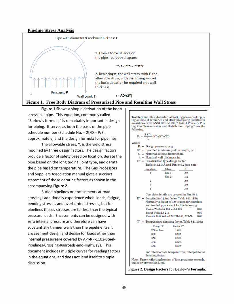
45
Pipeline Stress Analysis
Figure 1 Shows a simple derivation of the hoop
stress in a pipe. This equation, commonly called “Barlow’s formula,” is remarkably important in design for piping. It serves as both the basis of the pipe schedule number (Schedule No. = 2t/D = P/S, approximately) and the design formula for pipelines.
The allowable stress, Y, is the yield stress modified by three design factors. The design factors provide a factor of safety based on location, derate the pipe based on the longitudinal joint type, and derate the pipe based on temperature. The Gas Processors and Suppliers Association manual gives a succinct statement of those derating factors as shown in the accompanying Figure 2.
Buried pipelines or encasements at road crossings additionally experience wheel loads, fatigue, bending stresses and overburden stresses, but for pipelines theses stresses are far less than the typical pressure loads. Encasements can be designed with zero internal pressure and therefore can have substantially thinner walls than the pipeline itself. Encasement design and design for loads other than internal pressureare covered by API-RP-1102-Steel-Pipelines-Crossing-Railroads-and-Highways. This document includes multiple curves for reading factors in the equations, and does not lend itself to simple discussion.
Figure 2. Design Factors for Barlow’s Formula.
Figure 1. Free Body Diagram of Pressurized Pipe and Resulting Wall Stress
Executive Committee
Dr. Jay K. Lindly, Director UTCA The University of Alabama
Dr. Michael Hardin, Associate Director UTCA
The University of Alabama
Dr. Fouad H. Fouad, Associate Director UTCA The University of Alabama at Birmingham
Dr. Houssam A. Toutanji, Associate Director UTCA
The University of Alabama in Huntsville
Staff
Ms. Connie Harris, Secretary UTCA
Contact Information
University Transportation Center for Alabama 1105 Bevill Building
Box 870205 Tuscaloosa, AL 35487-0205
(205) 348-9925 (205) 348-6862 fax
http://utca.eng.ua.edu
University Transportation Center for Alabama