Embed Size (px)
Citation preview
Amazing Venture LTD Rev. 1
NDM457C EEPROM Programmer
User’s Guide
AMAZING VENTURE

AMAZING VENTURE NDM457C Programmer User’s Guide 2
TABLE OF CONTENTS
1. PREFACE ....................................................................................................................................... 3
2. CHECKLIST AND REQUIREMENTS ......................................................................................... 3
3. INSTALLATION AND USE ......................................................................................................... 4
3.1 PROGRAMMER CHECK AND CONNECTION TO PC ....................................................... 5
3.2 PROGRAMMER FIRMWARE UPDATE ............................................................................... 5
4. INTERFACE TYPES ..................................................................................................................... 6
4.1 IN-CIRCUIT PROGRAMMING ............................................................................................. 6
4.2 ON-BOARD PROGRAMMING .............................................................................................. 6
5. WORKING WITH TARGET EEPROM ........................................................................................ 7
5.1 In-Circuit EEPROM reading example ...................................................................................... 7
5.2 In-Circuit EEPROM programming example ............................................................................ 7
5.3 On-Board EEPROM reading example ...................................................................................... 8
5.4 On-Board EEPROM programming example ............................................................................ 8
5.5 Mileage Correction example ..................................................................................................... 9
6. FILE OPERATIONS .................................................................................................................... 13
6.1 LOAD FILE INTO BUFFER ................................................................................................. 13
6.2 SAVE FILE FROM BUFFER ................................................................................................ 13
7. ERRORS AND TROUBLESHOOTING ..................................................................................... 14
8. WARRANTY STATEMENT AND DISCLAIMER.................................................................... 15
9. APPENDIX ................................................................................................................................... 16
Figure 2. Wiring diagram for NDM457C EEPROM ....................................................................... 16
Figure 3. Wiring diagram for 51006 EEPROM ............................................................................... 16
Figure 4. Wiring diagram for 16911G EEPROM ............................................................................ 16
Figure 5. Wiring diagram for TC97101P EEPROM ....................................................................... 16

AMAZING VENTURE NDM457C Programmer User’s Guide 3
1. PREFACE
This manual will guide you through the installation and operation of the NDM457C
Programmer, referenced hereafter as the NDM457-Programmer.
The NDM457-Programmer has been designed for reading and programming of
Electrically-Erasable Programmable Read-Only Memory (EEPROM):
NDM457C
51006A
16911G
TC97101P
Note: Most number of devices can be programmed in two operating modes In-
Circuit and On-Board.
Note: Devices that not mentioned above in list can’t be guaranteed of correct
reading, programming by NDM457-Programmer.
2. CHECKLIST AND REQUIREMENTS
The following describes what items are supplied with the NDM457-Programmer and the
system requirements if used by a PC.
NDM457-Programmer – supplied
Cable -A DB9 “straight-thru” cable - supplied
NDM457-Programmer PC software on CD-ROM – Optional Extra
Desktop PC and a free Serial Communication Port (COM1...8)
Memory - Minimum 32 Mbytes
Display - Color SVGA display recommended
Power supply 12 Volt/200 mA linear power supply source
OS-MS-Windows (Win98, Win ME, Win2000/XP)
AMAZING VENTURE NDM457C Programmer User’s Guide 4
3. INSTALLATION AND USE
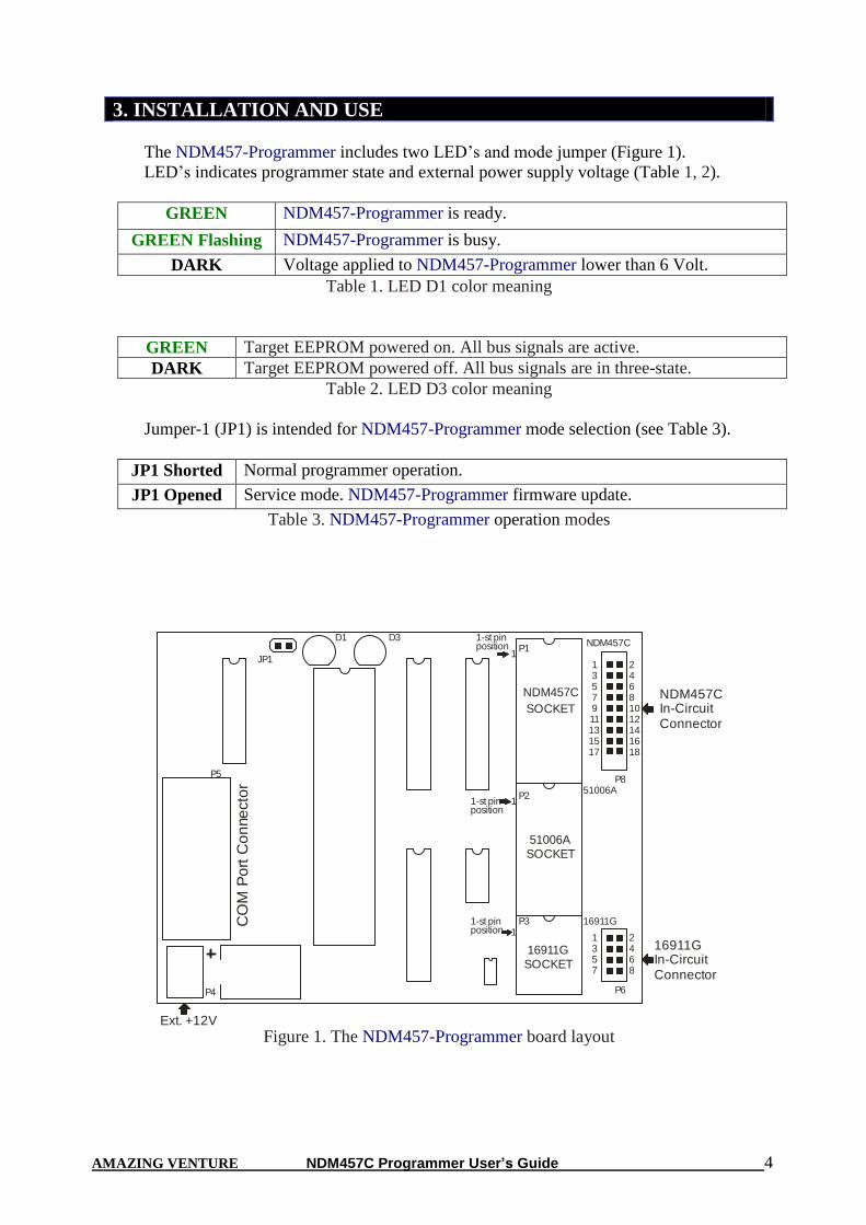
The NDM457-Programmer includes two LED’s and mode jumper (Figure 1).
LED’s indicates programmer state and external power supply voltage (Table 1, 2).
GREEN NDM457-Programmer is ready.
GREEN Flashing NDM457-Programmer is busy.
DARK Voltage applied to NDM457-Programmer lower than 6 Volt.
Table 1. LED D1 color meaning
GREEN Target EEPROM powered on. All bus signals are active.
DARK Target EEPROM powered off. All bus signals are in three-state.
Table 2. LED D3 color meaning
Jumper-1 (JP1) is intended for NDM457-Programmer mode selection (see Table 3).
JP1 Shorted Normal programmer operation.
JP1 Opened Service mode. NDM457-Programmer firmware update.
Table 3. NDM457-Programmer operation modes
1357911131517
24681012141618
1357
2468
NDM457C
SOCKET
1P1
NDM457C
51006ASOCKET
51006A1
P2
NDM457CIn-CircuitConnector
P8
P31
1-st pinposition
1-st pinposition
1-st pinposition
16911GSOCKET
16911G
P6
16911GIn-CircuitConnector
P4
P5
JP1
D1 D3
Ext. +12V
CO
M P
ort
Co
nne
cto
r
Figure 1. The NDM457-Programmer board layout
AMAZING VENTURE NDM457C Programmer User’s Guide 5
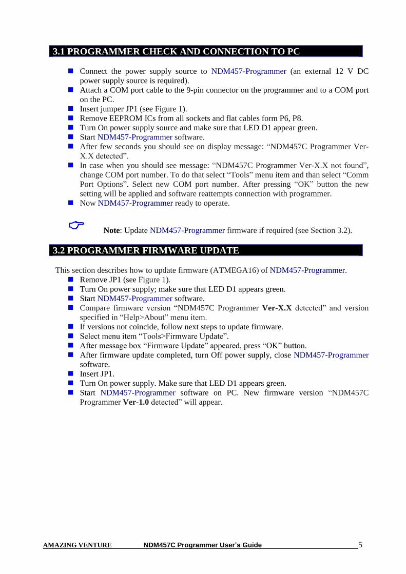
3.1 PROGRAMMER CHECK AND CONNECTION TO PC
Connect the power supply source to NDM457-Programmer (an external 12 V DC
power supply source is required).
Attach a COM port cable to the 9-pin connector on the programmer and to a COM port
on the PC.
Insert jumper JP1 (see Figure 1).
Remove EEPROM ICs from all sockets and flat cables form P6, P8.
Turn On power supply source and make sure that LED D1 appear green.
Start NDM457-Programmer software.
After few seconds you should see on display message: “NDM457C Programmer Ver-
X.X detected”.
In case when you should see message: “NDM457C Programmer Ver-X.X not found”,
change COM port number. To do that select “Tools” menu item and than select “Comm
Port Options”. Select new COM port number. After pressing “OK” button the new
setting will be applied and software reattempts connection with programmer.
Now NDM457-Programmer ready to operate.
Note: Update NDM457-Programmer firmware if required (see Section 3.2).
3.2 PROGRAMMER FIRMWARE UPDATE
This section describes how to update firmware (ATMEGA16) of NDM457-Programmer.
Remove JP1 (see Figure 1).
Turn On power supply; make sure that LED D1 appears green.
Start NDM457-Programmer software.
Compare firmware version “NDM457C Programmer Ver-X.X detected” and version
specified in “Help>About” menu item.
If versions not coincide, follow next steps to update firmware.
Select menu item “Tools>Firmware Update”.
After message box “Firmware Update” appeared, press “OK” button.
After firmware update completed, turn Off power supply, close NDM457-Programmer
software.
Insert JP1.
Turn On power supply. Make sure that LED D1 appears green.
Start NDM457-Programmer software on PC. New firmware version “NDM457C
Programmer Ver-1.0 detected” will appear.

AMAZING VENTURE NDM457C Programmer User’s Guide 6
4. INTERFACE TYPES
This section describes two interfaces, In-Circuit Programming (ICP) and On-Board
Programming (OBP) of NDM457-Programmer.
4.1 IN-CIRCUIT PROGRAMMING
In-Circuit programming interface is optional for NDM457-Programmer. Using of this mode
possible not for all EEPROM memory. For example 51006A EEPROM can not be read, program
in this mode. To use In-Circuit mode programmer must be connected with help of wire bus to
target EEPROM. For wiring information refer to Appendix Section. At the beginning of read,
program sequence programmer starts pins testing. If some pin(s) shorted to GND or +5V
programmer displays Error Message, for example: "BUS(s):0 must be disconnected from external
circuit". Such message indicates that BUS0 must be disconnected from external circuit. For pin
assignment information refer to Appendix section. Also if power supply protection errors appear in
this mode disconnect +5V signal from programmer and apply external power to explore board.
Note: Wire bus length used for connection between NDM457-Programmer and
target EEPROM must be 20 Cm (7 Inch) or lower.
Note: When using In-Circuit programming interface remove any EEPROM
from on-board sockets (see Figure 1).
4.2 ON-BOARD PROGRAMMING
On-Board programming interface is basic for NDM457-Programmer. Using of this mode
possible for all EEPROM memory. To use On-Board mode target EEPROM must be inserted in to
corresponding socket (See picture 1). At the beginning of read, program sequence programmer
starts pins testing. If some pin(s) shorted to GND or +5V programmer displays Error Message, for
example: "BUS(s):0 must be disconnected from external circuit". In this mode pin tester message
indicates that EEPROM has damaged pin connected internally to GND or +5Vpin. To make sure
of this, remove EEPROM from socket and start read, program sequence again. If error message
diapered, probably, EEPROM damaged. If error message remain, possible, programmer ports
damaged. In this case contact AMAZING VENTURE technical support for further instruction.
Note: Before insertion EEPROM into socket clean pins from colophony
otherwise correct reading, programming not guaranteed. Also superfluous solder
can lead to socket damage.
Note: When On-board programming interface used, remove cable from ICP
connectors (see Figure 1).

AMAZING VENTURE NDM457C Programmer User’s Guide 7
5. WORKING WITH TARGET EEPROM
This section contains EEPROM reading, programming examples in both On-Board and In-
Circuit programmer modes. When NDM457-Programmer successfully installed (see Section 3)
target EEPROM can be read, program and verify.
5.1 In-Circuit EEPROM reading example
Connect required pins from programmer to target EEPROM with help of wire bus.
Refer Appendix Section for wiring diagram.
Remove any EEPROM from On-Board sockets (see Figure 1).
Apply power to NDM457-Programmer. LED D1 became to green light (see Table 1).
Select “Read Sequence” panel in NDM457-Programmer software.
Select corresponding device in NDM457-Programmer software (“Device” button).
Press “EEPROM button.
Press “Start” button.
LED D3 on NDM457-Programmer became to green light. That means that +5 voltage
regulator switched on and VCC applied to target EEPROM.
When LED D1 on NDM457-Programmer became permanent green, reading completed.
Target EEPROM powered off.
After read sequence successfully completed it is necessarily to save memory dump to
file (see Section 6.2).
If some errors appeared during reading process refer to Section 7.
Note: Wire bus length used for connection between NDM457-Programmer and
target EEPROM must be 20 Cm (7 Inch) or lower.
Note: When using In-Circuit programming interface remove any EEPROM
from on-board sockets (see Figure 1).
5.2 In-Circuit EEPROM programming example
Connect required pins from programmer to target EEPROM with help of wire bus.
Refer Appendix Section for wiring diagram.
Remove any EEPROM from On-Board sockets (see Figure 1).
Apply power to NDM457-Programmer. LED D1 became to green light (see Table 1).
Select “Program Sequence” panel in NDM457-Programmer software.
Select corresponding device in NDM457-Programmer software (“Device” button).
Load EEPROM data from file (see Section 6.1) or enter data to Hex Editor.
Press “EEPROM button.
Press “Start” button.
LED D3 on NDM457-Programmer became to green light. That means that +5 voltage
regulator switched on and VCC applied to target EEPROM.
When LED D1 on NDM457-Programmer became permanent green, programming
completed. Target EEPROM powered off.
If some errors appeared during reading process refer to Section 7.
Note: Strongly recommended before EEPROM programming, for a first time,
read EEPROM contents and save it to file.
AMAZING VENTURE NDM457C Programmer User’s Guide 8
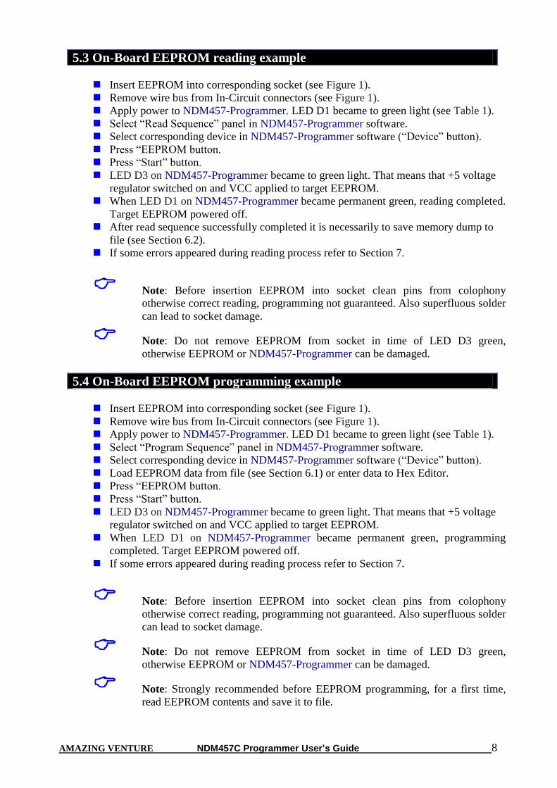
5.3 On-Board EEPROM reading example
Insert EEPROM into corresponding socket (see Figure 1).
Remove wire bus from In-Circuit connectors (see Figure 1).
Apply power to NDM457-Programmer. LED D1 became to green light (see Table 1).
Select “Read Sequence” panel in NDM457-Programmer software.
Select corresponding device in NDM457-Programmer software (“Device” button).
Press “EEPROM button.
Press “Start” button.
LED D3 on NDM457-Programmer became to green light. That means that +5 voltage
regulator switched on and VCC applied to target EEPROM.
When LED D1 on NDM457-Programmer became permanent green, reading completed.
Target EEPROM powered off.
After read sequence successfully completed it is necessarily to save memory dump to
file (see Section 6.2).
If some errors appeared during reading process refer to Section 7.
Note: Before insertion EEPROM into socket clean pins from colophony
otherwise correct reading, programming not guaranteed. Also superfluous solder
can lead to socket damage.
Note: Do not remove EEPROM from socket in time of LED D3 green,
otherwise EEPROM or NDM457-Programmer can be damaged.
5.4 On-Board EEPROM programming example
Insert EEPROM into corresponding socket (see Figure 1).
Remove wire bus from In-Circuit connectors (see Figure 1).
Apply power to NDM457-Programmer. LED D1 became to green light (see Table 1).
Select “Program Sequence” panel in NDM457-Programmer software.
Select corresponding device in NDM457-Programmer software (“Device” button).
Load EEPROM data from file (see Section 6.1) or enter data to Hex Editor.
Press “EEPROM button.
Press “Start” button.
LED D3 on NDM457-Programmer became to green light. That means that +5 voltage
regulator switched on and VCC applied to target EEPROM.
When LED D1 on NDM457-Programmer became permanent green, programming
completed. Target EEPROM powered off.
If some errors appeared during reading process refer to Section 7.
Note: Before insertion EEPROM into socket clean pins from colophony
otherwise correct reading, programming not guaranteed. Also superfluous solder
can lead to socket damage.
Note: Do not remove EEPROM from socket in time of LED D3 green,
otherwise EEPROM or NDM457-Programmer can be damaged.
Note: Strongly recommended before EEPROM programming, for a first time,
read EEPROM contents and save it to file.
AMAZING VENTURE NDM457C Programmer User’s Guide 9
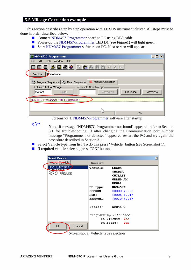
5.5 Mileage Correction example
This section describes step by step operation with LEXUS instrument cluster. All steps must be
done in order described below.
Connect NDM457-Programmer board to PC using DB9 cable.
Power-up the NDM457-Programmer LED D1 (see Figure1) will light green.
Start NDM457-Programmer software on PC. Next screen will appear:
Screenshot 1. NDM457-Programmer software after startup
Note: If message "NDM457C Programmer not found" appeared refer to Section
3.1 for troubleshooting. If after changing the Communication port number
message "Programmer not detected" appeared restart the PC and try again the
procedure described in Section 3.1.
Select Vehicle type from list. To do this press "Vehicle" button (see Screenshot 1).
If required vehicle selected, press "OK" button.
Screenshot 2. Vehicle type selection
AMAZING VENTURE NDM457C Programmer User’s Guide 10
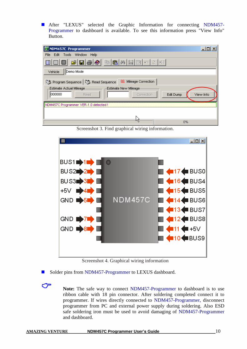
After "LEXUS" selected the Graphic Information for connecting NDM457-
Programmer to dashboard is available. To see this information press "View Info"
Button.
Screenshot 3. Find graphical wiring information.
Screenshot 4. Graphical wiring information
Solder pins from NDM457-Programmer to LEXUS dashboard.
Note: The safe way to connect NDM457-Programmer to dashboard is to use
ribbon cable with 18 pin connector. After soldering completed connect it to
programmer. If wires directly connected to NDM457-Programmer, disconnect
programmer from PC and external power supply during soldering. Also ESD
safe soldering iron must be used to avoid damaging of NDM457-Programmer
and dashboard.
AMAZING VENTURE NDM457C Programmer User’s Guide 11
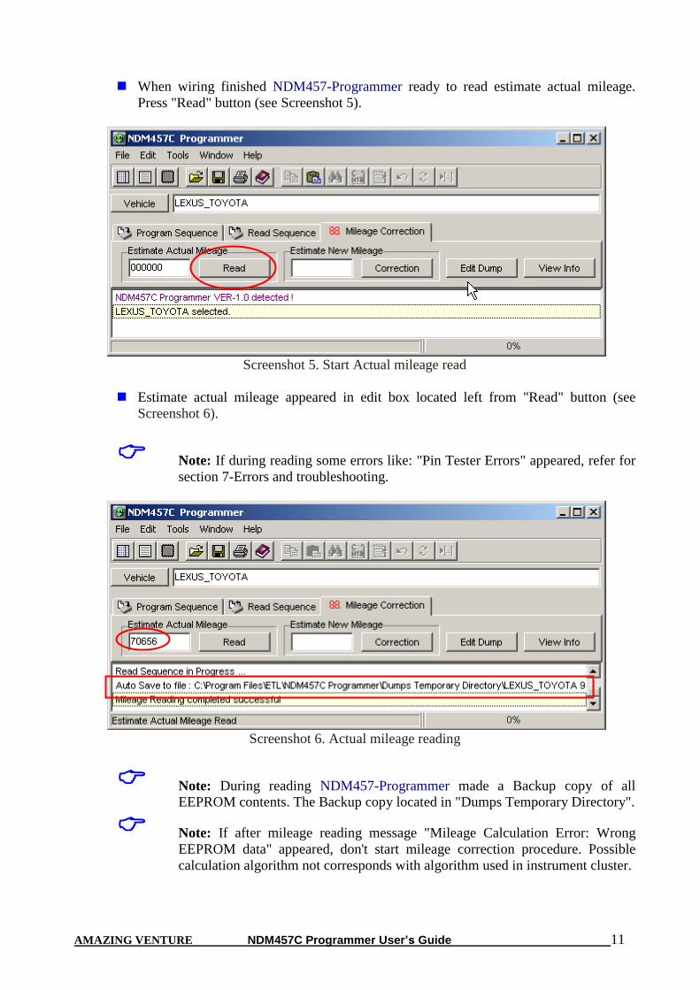
When wiring finished NDM457-Programmer ready to read estimate actual mileage.
Press "Read" button (see Screenshot 5).
Screenshot 5. Start Actual mileage read
Estimate actual mileage appeared in edit box located left from "Read" button (see
Screenshot 6).
Note: If during reading some errors like: "Pin Tester Errors" appeared, refer for
section 7-Errors and troubleshooting.
Screenshot 6. Actual mileage reading
Note: During reading NDM457-Programmer made a Backup copy of all
EEPROM contents. The Backup copy located in "Dumps Temporary Directory".
Note: If after mileage reading message "Mileage Calculation Error: Wrong
EEPROM data" appeared, don't start mileage correction procedure. Possible
calculation algorithm not corresponds with algorithm used in instrument cluster.
AMAZING VENTURE NDM457C Programmer User’s Guide 12
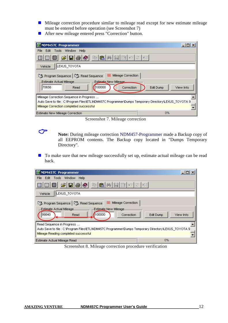
Mileage correction procedure similar to mileage read except for new estimate mileage
must be entered before operation (see Screenshot 7)
After new mileage entered press "Correction" button.
Screenshot 7. Mileage correction
Note: During mileage correction NDM457-Programmer made a Backup copy of
all EEPROM contents. The Backup copy located in "Dumps Temporary
Directory".
To make sure that new mileage successfully set up, estimate actual mileage can be read
back.
Screenshot 8. Mileage correction procedure verification

AMAZING VENTURE NDM457C Programmer User’s Guide 13
6. FILE OPERATIONS This section describes basic rules working with files. Memory dump from Hex Editor (Buffer)
can be load/save from/to hard disk. Also short descriptions such as project name, EEPROM type
and memory cell assignment can be done for future fast remind. NDM457-Programmer accepts
tree types of file formats:
BIN (Binary format)
Motorola S-Record (4 byte address)
Motorola S-Record (6 byte address)
EEF (Extended ETL Format)
6.1 LOAD FILE INTO BUFFER Select “File>Open” menu item.
Press “Browse” button.
In File Open Dialog window, select file witch need to be open.
Press “Open” button.
Than opposite “Auto Format Detected:” text, select correct file format. Note that software
try automatically detects file format, but unknown records in file will fail this detection.
“Load Entire file” check box must be checked if automatically loading procedures
required.
Than press “OK” button.
Sometimes load data from file to specific buffer allocations required. For Example if required
load buffer from $B600 address from binary file beginning from $0000 address follow next steps:
Select “File>Open” menu item.
Press “Browse” button.
In File Open Dialog window, select file which need to be open.
Press “Open” button.
Than, opposite “Auto Format Detected:” select Binary format.
Uncheck “Load Entire File” check box.
In field “Offset Value to Place Data to Buffer:” enter 0xB600.
Than press “OK” button.
Now data placed to Hex Editor Buffer from the beginning of 0xB600 address.
If more complicated operations with files required, for example load Hex Editor Buffer from
many files “Lowest Address From File To Load”, “Highest Address From File To Load” and
“Clear Buffer Before Loading File” options are available.
6.2 SAVE FILE FROM BUFFER Select “File>Save” menu item.
Press “Browse” button.
Select directory in which file will be saved.
Type file name, for example “test1”
Press “Save” button.
Than select format in which file will be saved*.
Press “OK” button.
Note: Use EEF Format for future “Load File Into Buffer” automatically
processing. Also, only in EEF Format Project Description, Device Name and
Memory Cells attributes can be saved.
AMAZING VENTURE NDM457C Programmer User’s Guide 14
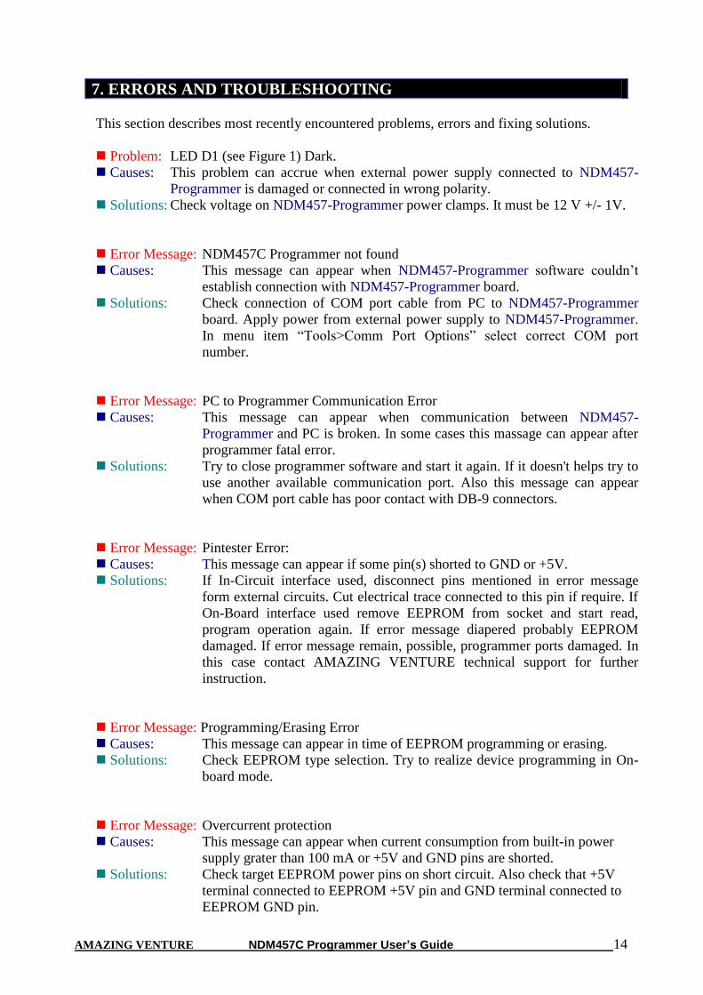
7. ERRORS AND TROUBLESHOOTING
This section describes most recently encountered problems, errors and fixing solutions.
Problem: LED D1 (see Figure 1) Dark.
Causes: This problem can accrue when external power supply connected to NDM457-
Programmer is damaged or connected in wrong polarity.
Solutions: Check voltage on NDM457-Programmer power clamps. It must be 12 V +/- 1V.
Error Message: NDM457C Programmer not found
Causes: This message can appear when NDM457-Programmer software couldn’t
establish connection with NDM457-Programmer board.
Solutions: Check connection of COM port cable from PC to NDM457-Programmer
board. Apply power from external power supply to NDM457-Programmer.
In menu item “Tools>Comm Port Options” select correct COM port
number.
Error Message: PC to Programmer Communication Error
Causes: This message can appear when communication between NDM457-
Programmer and PC is broken. In some cases this massage can appear after
programmer fatal error.
Solutions: Try to close programmer software and start it again. If it doesn't helps try to
use another available communication port. Also this message can appear
when COM port cable has poor contact with DB-9 connectors.
Error Message: Pintester Error:
Causes: This message can appear if some pin(s) shorted to GND or +5V.
Solutions: If In-Circuit interface used, disconnect pins mentioned in error message
form external circuits. Cut electrical trace connected to this pin if require. If
On-Board interface used remove EEPROM from socket and start read,
program operation again. If error message diapered probably EEPROM
damaged. If error message remain, possible, programmer ports damaged. In
this case contact AMAZING VENTURE technical support for further
instruction.
Error Message: Programming/Erasing Error
Causes: This message can appear in time of EEPROM programming or erasing.
Solutions: Check EEPROM type selection. Try to realize device programming in On-
board mode.
Error Message: Overcurrent protection
Causes: This message can appear when current consumption from built-in power
supply grater than 100 mA or +5V and GND pins are shorted.
Solutions: Check target EEPROM power pins on short circuit. Also check that +5V
terminal connected to EEPROM +5V pin and GND terminal connected to
EEPROM GND pin.

AMAZING VENTURE NDM457C Programmer User’s Guide 15
Error Message: +10V Power Supply voltage out of range
Causes: This error can appear if voltage on +10V pin lower then 7V.
Solutions: If In-Circuit interface used, disconnect +10V pin form external circuits. Cut
electrical trace connected to this pin if require. If On-Board interface used
remove EEPROM from socket and start read, program operation again. If
error message diapered probably EEPROM damaged. If error message
remain, possible, programmer ports damaged. In this case contact
AMAZING VENTURE technical support for further instruction.
Error Message: WRONG SUBROUTINE CALL
WRONG DEVICE TYPE
Causes: These messages can appear when fatal problems with NDM457-
Programmer hardware/firmware occurred.
Solutions: Contact AMAZING VENTURE technical support.
Note: NDM457-Programmer has Log Window which can be stored to file. To
perform this operation right clicks on Log Window. Than click on “Save to
ndm457p.log file“ menu item. Now this file can be found in the same directory
as NDM457-Programmer software. Log File can be send by E-mail to
[email protected] for non described problem solution.
AMAZING VENTURE warrants that Product delivered shall conform to applicable. Report
any defects for a 30 days period, from the applicable data on invoice.
All AMAZING VENTURE 's product are intended for lawful service, repair or replacement of
various electronic equipment with the laws of the country in which the product is being sold or
used.
8. WARRANTY STATEMENT AND DISCLAIMER
AMAZING VENTURE NDM457C Programmer User’s Guide 16
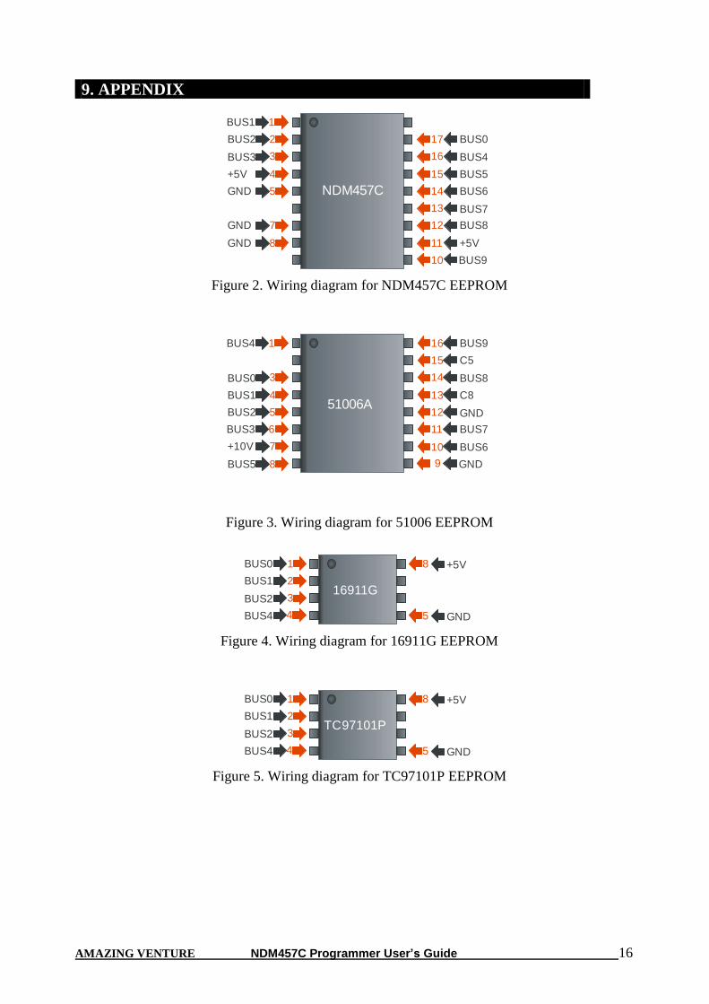
NDM457C
1BUS1
2BUS2
3BUS3
4+5V
5GND
7GND
8GND
17 BUS0
16 BUS4
15 BUS5
14 BUS6
12 BUS8
11 +5V
10
13 BUS7
BUS9
Figure 2. Wiring diagram for NDM457C EEPROM
51006A
1BUS4
3BUS0
4BUS1
5BUS2
7+10V
8BUS5
16 BUS9
15 C5
14 BUS8
13 C8
11 BUS7
10 BUS6
9
12 GND
GND
6BUS3
Figure 3. Wiring diagram for 51006 EEPROM
16911G
1BUS0
2BUS1
3BUS2
8 +5V
5 GND4BUS4
Figure 4. Wiring diagram for 16911G EEPROM
TC97101P
1BUS0
2BUS1
3BUS2
8 +5V
5 GND4BUS4
Figure 5. Wiring diagram for TC97101P EEPROM
9. APPENDIX