Embed Size (px)
Citation preview
NEB 6500NEB 6500 R
4M898-0_letter
NEB 6500 and NEB 6500 R
Table of Contents1 Technical features 51.1 Main features 51.2 Dimensions and weights 51.3 Description of the components 5
2 Introduction 52.1 General safety rules 5
3 Installation 63.1 Materials supplied 63.2 Preliminary operations 6
4 Positioning 64.1 Wall installation 74.2 Hanging installation 84.3 Electrical connections 84.3.1 Wiring diagram 94.3.2 Cabling 94.4 Hydraulic connections 94.5 Final operations 10
5 Operation & Control 105.1 Preliminary checking 105.2 Starting 105.3 Stopping 10
6 Electronic control 106.1 The electronic board 106.1.1 Dip switches 116.2 Adjusting the humidification capacity 116.3 The washing/reset cycle 11
7 Maintenance 127.1 Cleaning the air filter 127.2 Drain siphon 127.3 Feeding solenoid valve. 127.4 Performing the washing/reset cycle 12
8 Storing 138.1 Points to check before and after a long period of inactivity 138.1.1 Before 138.1.2 After 13
9 Disposal of the product 13
5M898-0_letter
NEB 6500 and NEB 6500 R
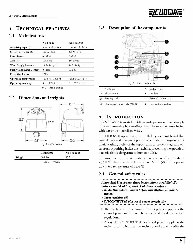
1 Technical features1.1 Main features
NEB 6500 NEB 6500 RAtomizing capacity 3.3 - 14.3 lbs/hour 3.3 - 14.3 lbs/hour
Electric power supply 120 V, 60 Hz 120 V, 60 Hz
Rated Power 0.23 kW 0.3 kW
Air Flow 164.8 cfm 164.8 cfm
Water Supply Pressure 14.5 - 145 psi 14.5 - 145 psi
Supply Tank Water Content 0.12 lbs 0.12 lbs
Protection Rating IPX4
Operating Temperature +33.8 °F … +95 °F -28.4 °F … +95 °F
Operating humidity 0 … 100% R.H. n.c. 0…100% R.H. n.c.
Tab. 1 - Main features
1.2 Dimensions and weights
Fig. 1 - Dimensions
NEB 6500 NEB 6500 RWeight 38.8 lbs 43.2 lbs
Tab. 2 - Weights
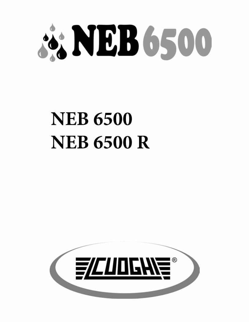
1.3 Description of the components
Fig. 2 - Main components
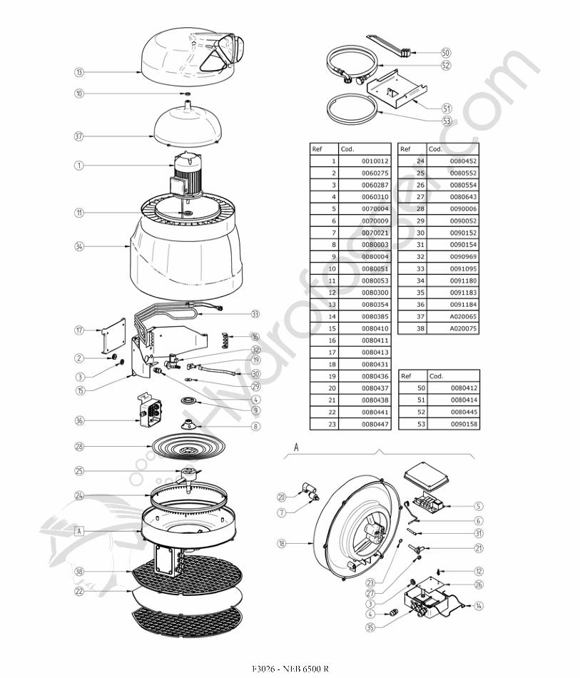
1 Air diffuser 5 Suction cone
2 Electric motor 6 Air filter
3 Rotating disk 7 External junction box
4 Heating resistance (only 6500 R) 8 Internal junction box
2 IntroductionThe NEB 6500 is an air humidifier and operates on the principle of water atomizing by centrifugation. The machine must be fed with tap or demineralized water.The NEB 6500 operation is controlled by a circuit board that runs the normal machine operations and also the regular auto-matic washing cycles of the supply tank to prevent stagnant wa-ter from depositing inside the machine, preventing the growth of bacteria that is dangerous to human health.The machine can operate under a temperature of up to about +33.8 °F. The anti-freeze device allows NEB 6500 R to operate down to a temperature of 28.4 °F.
2.1 General safety rules
Attention! Please read these instructions carefully! <To reduce the risk of fire, electrical shock or injury:• READ this entire manual before installation or mainte-
nance.• Turn machine off.• DISCONNECT all electrical power completely.
» The machine must be connected to a power supply via the control panel and in compliance with all local and federal regulations.
» Always DISCONNECT the electrical power supply at the main cutoff switch on the main control panel. Verify the
6M898-0_letter
NEB 6500 and NEB 6500 R
unit has no power with a voltage tester. » Make sure no tools or extra parts have been left in the ma-
chine prior to reinstallation and powering up the unit. » Installation and maintenance of the machine must be done
by expert and qualified personnel, capable of carrying out the work according to the instructions found in this manual.
» This machine has been designed to humidify the air; it is not advisable to use the machine for anything other than humidity control.
» Any use other than that described in this manual is to be considered improper, potentially damaging and dangerous.
» Carefully keep these instructions for future reference.
This humidifier is NOT intended for people, children included, with limited physical or mental capabilities or without enough experience concerning the use of it. Keep it away from children and animals.
3 Installation3.1 Materials suppliedThe following materials are supplied with the machine. Check that all the materials listed below are in the pack before starting work.
» N.1 humidifier mod. NEB 6500 or NEB 6500 R; » N.1 technical installation manual; » N.4 Wall bolt anchors with screws; » N.1 Fastening brackets for wall mounting; » N.3 Brackets for hanging installation; » N.1 safety screws: M6×20, with hexagonal cavity; » N.1 washers: Ø6×12; » N.1 Water supply pipe 59 inches long, with screw connec-
tors G3/4; » N. 1 water drain pipe 59 inches long and 0.39 inches inter-
nal diameter » N. 3 cable straps;
3.2 Preliminary operations To make the NEB 6500 operative you need:
• an electrical control box with a 120 V circuit for power with a ground connection and protection devices;
Installation must comply with the safety requirements of the local regulations in force.
• Water supply connection • Water drain connection
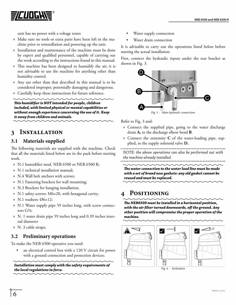
It is advisable to carry out the operations listed below before starting the actual installation.First, connect the hydraulic inputs under the rear bracket as shown in Fig. 3.
Fig. 3 - Main hydraulic connections
Refer to Fig. 3 and: » Connect the supplied pipe, going to the water discharge
drain A, to the discharge elbow bend B. » Connect the extremity C of the water-loading pipe, sup-
plied, to the supply solenoid valve D.
NOTE: the above operations can also be performed out with the machine already installed.
The water connection to the water load line must be made with a set of brand new gaskets: any old gasket cannot be reused and must be replaced.
4 PositioningThe NEB6500 must be installed in a horizontal position, with the air filter turned downwards, off the ground. Any other position will compromise the proper operation of the machine.
Fig. 4 - Inclination
7M898-0_letter
NEB 6500 and NEB 6500 R
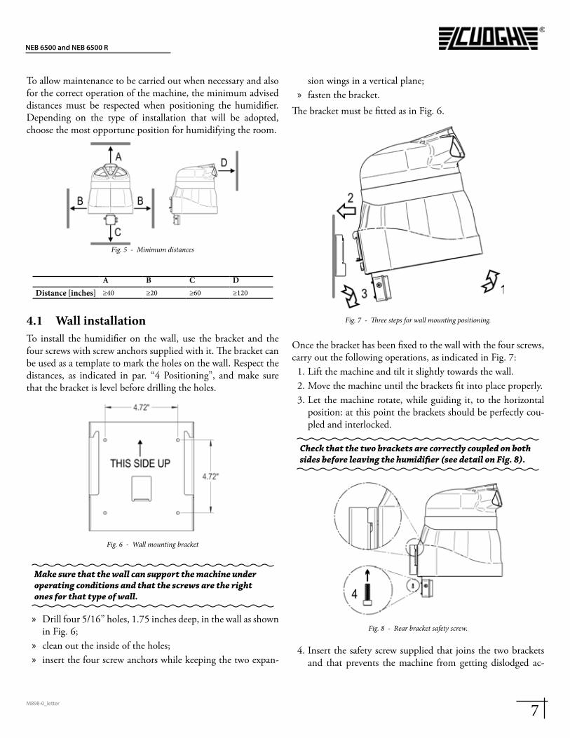
To allow maintenance to be carried out when necessary and also for the correct operation of the machine, the minimum advised distances must be respected when positioning the humidifier. Depending on the type of installation that will be adopted, choose the most opportune position for humidifying the room.
Fig. 5 - Minimum distances
A B C DDistance [inches] ≥40 ≥20 ≥60 ≥120
4.1 Wall installationTo install the humidifier on the wall, use the bracket and the four screws with screw anchors supplied with it. The bracket can be used as a template to mark the holes on the wall. Respect the distances, as indicated in par. “4 Positioning”, and make sure that the bracket is level before drilling the holes.
Fig. 6 - Wall mounting bracket
Make sure that the wall can support the machine under operating conditions and that the screws are the right ones for that type of wall.
» Drill four 5/16” holes, 1.75 inches deep, in the wall as shown in Fig. 6;
» clean out the inside of the holes; » insert the four screw anchors while keeping the two expan-
sion wings in a vertical plane; » fasten the bracket.
The bracket must be fitted as in Fig. 6.
Fig. 7 - Three steps for wall mounting positioning.
Once the bracket has been fixed to the wall with the four screws, carry out the following operations, as indicated in Fig. 7:
1. Lift the machine and tilt it slightly towards the wall.2. Move the machine until the brackets fit into place properly.3. Let the machine rotate, while guiding it, to the horizontal
position: at this point the brackets should be perfectly cou-pled and interlocked.
Check that the two brackets are correctly coupled on both sides before leaving the humidifier (see detail on Fig. 8).
Fig. 8 - Rear bracket safety screw.
4. Insert the safety screw supplied that joins the two brackets and that prevents the machine from getting dislodged ac-
8M898-0_letter
NEB 6500 and NEB 6500 R
cidentally (see Fig. 8).
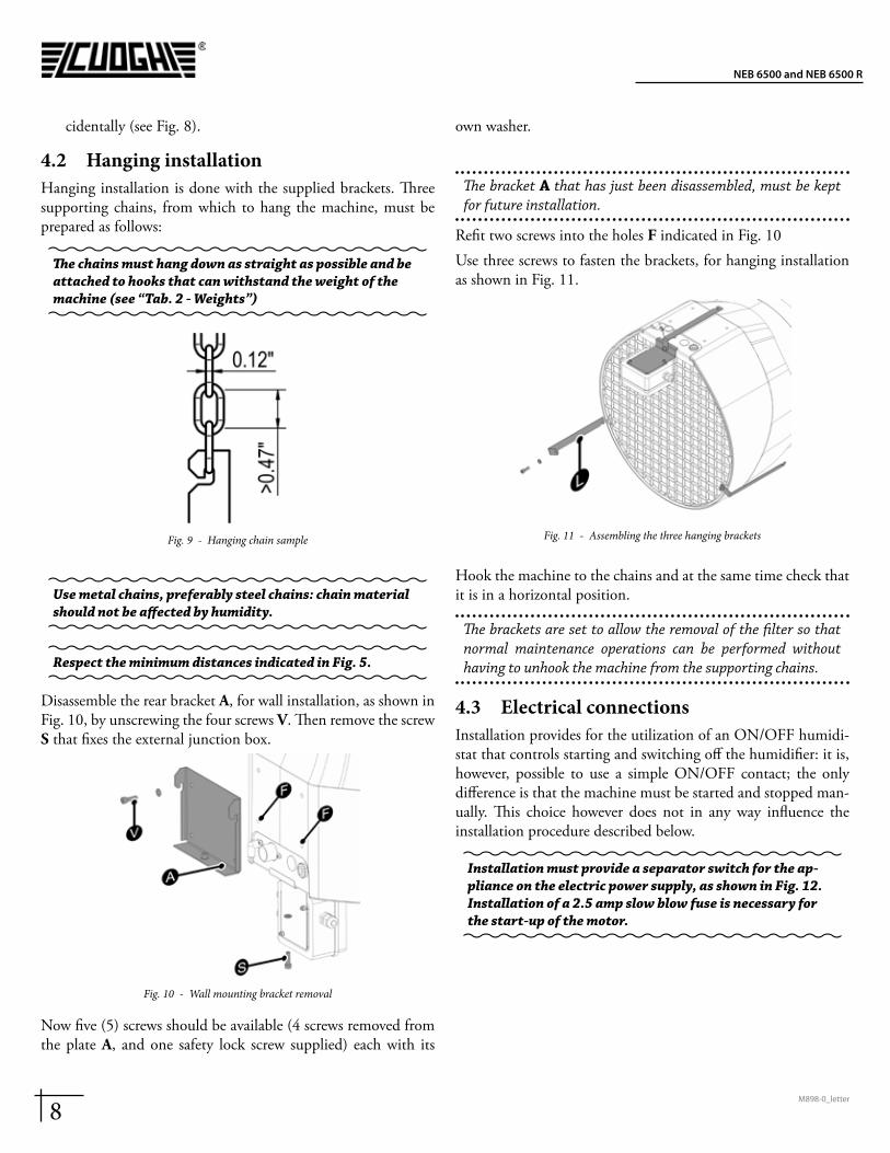
4.2 Hanging installationHanging installation is done with the supplied brackets. Three supporting chains, from which to hang the machine, must be prepared as follows:
The chains must hang down as straight as possible and be attached to hooks that can withstand the weight of the machine (see “Tab. 2 - Weights”)
Fig. 9 - Hanging chain sample
Use metal chains, preferably steel chains: chain material should not be affected by humidity.
Respect the minimum distances indicated in Fig. 5.
Disassemble the rear bracket A, for wall installation, as shown in Fig. 10, by unscrewing the four screws V. Then remove the screw S that fixes the external junction box.
Fig. 10 - Wall mounting bracket removal
Now five (5) screws should be available (4 screws removed from the plate A, and one safety lock screw supplied) each with its
own washer.
The bracket A that has just been disassembled, must be kept for future installation.
Refit two screws into the holes F indicated in Fig. 10Use three screws to fasten the brackets, for hanging installation as shown in Fig. 11.
Fig. 11 - Assembling the three hanging brackets
Hook the machine to the chains and at the same time check that it is in a horizontal position.
The brackets are set to allow the removal of the filter so that normal maintenance operations can be performed without having to unhook the machine from the supporting chains.
4.3 Electrical connectionsInstallation provides for the utilization of an ON/OFF humidi-stat that controls starting and switching off the humidifier: it is, however, possible to use a simple ON/OFF contact; the only difference is that the machine must be started and stopped man-ually. This choice however does not in any way influence the installation procedure described below.
Installation must provide a separator switch for the ap-pliance on the electric power supply, as shown in Fig. 12. Installation of a 2.5 amp slow blow fuse is necessary for the start-up of the motor.
9M898-0_letter
NEB 6500 and NEB 6500 R
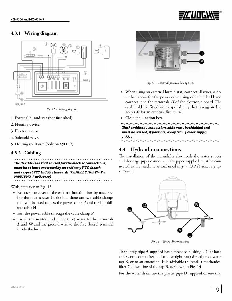
4.3.1 Wiring diagram
Fig. 12 - Wiring diagram
1. External humidistat (not furnished).2. Floating device.3. Electric motor.4. Solenoid valve.5. Heating resistance (only on 6500 R)
4.3.2 Cabling
The flexible lead that is used for the electric connections, must be at least protected by an ordinary PVC sheath and respect 227 IEC 53 standards (CENELEC H05VV-F or H05VVH2-F or better)
With reference to Fig. 13: » Remove the cover of the external junction box by unscrew-
ing the four screws. In the box there are two cable clamps that will be used to pass the power cable P and the humidi-stat cable H.
» Pass the power cable through the cable clamp P. » Fasten the neutral and phase (live) wires to the terminals L and W and the ground wire to the free (loose) terminal inside the box.
Fig. 13 - External junction box opened.
» When using an external humidistat, connect all wires as de-scribed above for the power cable using cable holder H and connect it to the terminals H of the electronic board. The cable holder is fitted with a special plug that is suggested to keep safe for an eventual future use.
» Close the junction box.
The humidistat connection cable must be shielded and must be passed, if possible, away from power supply cables.
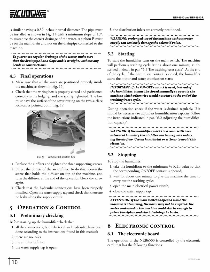
4.4 Hydraulic connectionsThe installation of the humidifier also needs the water supply and drainage pipes connected. The pipes supplied must be con-nected to the machine as explained in par. “3.2 Preliminary op-erations”.
Fig. 14 - Hydraulic connections
The supply pipe A supplied has a threaded bushing G3/4 at both ends: connect the free end (the straight one) directly to a water tap B, or to an extension. It is advisable to install a mechanical filter C down-line of the tap B, as shown in Fig. 14.For the water drain use the plastic pipe D supplied or one that
10M898-0_letter
NEB 6500 and NEB 6500 R
is similar having a 0.39 inches internal diameter. The pipe must be installed as shown in Fig. 14 with a minimum slope of 10°, to guarantee the correct drainage of the water. A siphon E must be on the main drain and not on the drainpipe connected to the machine.
To guarantee regular drainage of the water, make sure that the drainpipe has a slope and is straight, without any bends or constrictions.
4.5 Final operations » Make sure that all the wires are positioned properly inside
the machine as shown in Fig. 15. » Check that the wiring box is properly closed and positioned
correctly in its lodging, and the spring tightened. The box must have the surface of the cover resting on the two surface locators as pointed out in Fig. 17
Fig. 15 - The internal junction box
» Replace the air filter and tighten the three supporting screws. » Direct the outlets of the air diffuser. To do this, loosen the
screw that holds the diffuser on top of the machine, and turn the diffuser: at the end of the operation block the screw again.
» Check that the hydraulic connections have been properly installed. Open the water supply tap and check that there are no leaks along the supply circuit
5 Operation & Control5.1 Preliminary checkingBefore starting up the humidifier check that:
1. all the connections, both electrical and hydraulic, have been done according to the instructions found in this manual;
2. there are no leaks;3. the air filter is fitted;4. the water supply tap is open;
5. the distribution inlets are correctly positioned.
WARNING: prolonged use of the machine without water supply can seriously damage the solenoid valve.
5.2 StartingTo start the humidifier turn on the main switch. The machine will perform a washing cycle lasting about one minute, as de-scribed in detail in par. “6.3 The washing/reset cycle”. At the end of the cycle, if the humidistat contact is closed, the humidifier starts the motor and water atomization starts.
IMPORTANT: if the ON/OFF contact is used, instead of the humidistat, it must be closed manually to operate the machine which otherwise would not start at the end of the washing/reset cycle.
During operation check if the water is drained regularly. If it should be necessary to adjust its humidification capacity, follow the instructions indicated in par. “6.2 Adjusting the humidifica-tion capacity”.
WARNING: if the humidifier works in a room with over saturated humidity the air filter can impregnate reduc-ing the air flow. Use an humidistat or a timer to avoid this situation.
5.3 StoppingTo stop the humidifier:
1. take the humidistat to the minimum % R.H. value so that the corresponding ON/OFF contact is opened;
2. wait for about one minute to give the machine the time to carry out the washing cycle;
3. open the main electrical power switch;4. close the water supply tap.
ATTENTION: if the main switch is opened while the machine is atomizing, the basin may not be emptied: the water contained in the machine could still be enough to prime the siphon and start draining the basin.
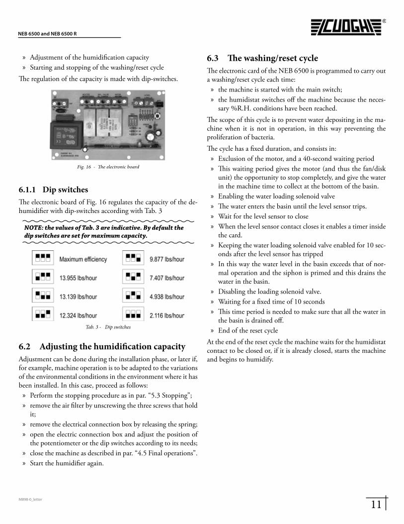
6 Electronic control6.1 The electronic boardThe operation of the NEB6500 is controlled by the electronic card, that has the following functions:
11M898-0_letter
NEB 6500 and NEB 6500 R
» Adjustment of the humidification capacity » Starting and stopping of the washing/reset cycle
The regulation of the capacity is made with dip-switches.
Fig. 16 - The electronic board
6.1.1 Dip switchesThe electronic board of Fig. 16 regulates the capacity of the de-humidifier with dip-switches according with Tab. 3
NOTE: the values of Tab. 3 are indicative. By default the dip switches are set for maximum capacity.
Tab. 3 - Dip switches
6.2 Adjusting the humidification capacityAdjustment can be done during the installation phase, or later if, for example, machine operation is to be adapted to the variations of the environmental conditions in the environment where it has been installed. In this case, proceed as follows:
» Perform the stopping procedure as in par. “5.3 Stopping”; » remove the air filter by unscrewing the three screws that hold
it; » remove the electrical connection box by releasing the spring; » open the electric connection box and adjust the position of
the potentiometer or the dip switches according to its needs; » close the machine as described in par. “4.5 Final operations”. » Start the humidifier again.
6.3 The washing/reset cycleThe electronic card of the NEB 6500 is programmed to carry out a washing/reset cycle each time:
» the machine is started with the main switch; » the humidistat switches off the machine because the neces-
sary %R.H. conditions have been reached.The scope of this cycle is to prevent water depositing in the ma-chine when it is not in operation, in this way preventing the proliferation of bacteria.The cycle has a fixed duration, and consists in:
» Exclusion of the motor, and a 40-second waiting period » This waiting period gives the motor (and thus the fan/disk
unit) the opportunity to stop completely, and give the water in the machine time to collect at the bottom of the basin.
» Enabling the water loading solenoid valve » The water enters the basin until the level sensor trips. » Wait for the level sensor to close » When the level sensor contact closes it enables a timer inside
the card. » Keeping the water loading solenoid valve enabled for 10 sec-
onds after the level sensor has tripped » In this way the water level in the basin exceeds that of nor-
mal operation and the siphon is primed and this drains the water in the basin.
» Disabling the loading solenoid valve. » Waiting for a fixed time of 10 seconds » This time period is needed to make sure that all the water in
the basin is drained off. » End of the reset cycle
At the end of the reset cycle the machine waits for the humidistat contact to be closed or, if it is already closed, starts the machine and begins to humidify.
12M898-0_letter
NEB 6500 and NEB 6500 R
7 MaintenanceThe NEB6500 is designed to guarantee efficient and faultless operation for a long time. It is however, necessary to carry out some simple maintenance operations, how often they are car-ried out depends on the environmental conditions in which the NEB6500 operates and on the quality of the water supply.
ATTENTION: Before carrying out any maintenance open (switch off) the main switch and wait for the machine to come to a come to a perfect standstill. Close the water sup-ply tap. Keep to the general safety rules found in par. “2.1 General safety rules”. Before starting the machine again, duly check everything as described in this manual.
7.1 Cleaning the air filter
Fig. 17 - air filter.
The filter must be cleaned periodically, since the accumulation of dirt and dust reduces air delivery and so the efficiency of the machine.
» Remove the filter by unscrewing the three screws holding it; » separate the two plastic grids A from the filter material B;
Clean the filter B with a vacuum cleaner or immerse it in slightly soapy water, and rinse: dry without wringing. Filter MUST BE COMPLETELY DRY before reinstallation.
ATTENTION: never enable the humidifier without the air filter fitted! The air filter is composed of three pieces that must be assembled in such a way that the filter material B is enclosed between the two plastic grids A (Fig. 17).
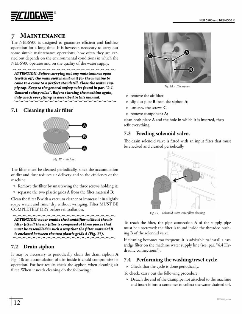
7.2 Drain siphonIt may be necessary to periodically clean the drain siphon A Fig. 18: an accumulation of dirt inside it could compromise its operation. For best results check the syphon when cleaning air filter. When it needs cleaning do the following :
Fig. 18 - The siphon
» remove the air filter; » slip out pipe B from the siphon A; » unscrew the screws C; » remove component A;
clean both piece A and the hole in which it is inserted, then refit everything.
7.3 Feeding solenoid valve.The drain solenoid valve is fitted with an input filter that must be checked and cleaned periodically.
Fig. 19 - Solenoid valve water filter cleaning
To reach the filter, the pipe connection A of the supply pipe must be unscrewed: the filter is found inside the threaded bush-ing B of the solenoid valve.If cleaning becomes too frequent, it is advisable to install a car-tridge filter on the machine water supply line (see: par. “4.4 Hy-draulic connections”).
7.4 Performing the washing/reset cycle » Check that the cycle is done periodically.
To check, carry out the following procedure: » Detach the end of the drainpipe not attached to the machine
and insert it into a container to collect the water drained off.
13M898-0_letter
NEB 6500 and NEB 6500 R
» Stop the humidifier by turning off the control humidistat: this starts the washing cycle.
If the cycle does not go on regularly, the water basin must be cleaned and the siphon.
ATTENTION: The NEB6500 is an air humidifier, so any other use to which it might be put, and which is not what it was designed for (for example spraying insecticides, disinfectants, essences or any product other than water) may be dangerous or compromise the good operation of the machine.
8 Storing » Keep the machine in an environment with a temperature
range between 14 °F and 140 °F. » When the machine is still packed, keep it upright. » Do not put any other heavy things on the box.
8.1 Points to check before and after a long period of inactivity
8.1.1 Before » Disconnect the electric connections and close the supply wa-
ter ON/OFF taps; » Cover the machine to protect it from the dust.
8.1.2 After » Check the state of the air filter and clean it if necessary. » Check that the float switch is operational by moving it, and
check that the fan/disk unit turns freely. » Make sure that all the connections have been done correctly,
according to instructions. » See that the washing/reset cycle is tested, as described at par.
“7.4 Performing the washing/reset cycle” of the following manual.
9 Disposal of the productThe machine is mainly composed of parts in plastic, and some parts in metal; both materials can be recycled. Before disposing of the product it is advisable to separate the plastic parts (cap, fan, foils, etc.) from the metal parts (motor, installation flanges). Remove the electronic card from the electric connection box and see to its disposal according to the regulations in force.

14M898-0_letter
NEB 6500 and NEB 6500 R
Notes
15M898-0_letter
NEB 6500 and NEB 6500 R
Notes

CUOGHI s.r.l.via Garibaldi, 1535020 Albignasego (PD) - Italyphone +39 049 8629099fax +39 049 [email protected]


![[XLS] and Construction... · Web view36 6500 30 3000 9 36 6500 62 4500 42 6500 37 3000 19 17 36 6500 42 6000 19 17 41 6500 36 3000 14 11 31 6500 33 6000 10 8 33 6500 31 3000 10 8](https://img.pdfslide.net/doc/110x75/5aaaff237f8b9a8f498b52b0/xls-and-constructionweb-view36-6500-30-3000-9-36-6500-62-4500-42-6500-37-3000.jpg)