Embed Size (px)
Citation preview
6000 ENDecember 2005
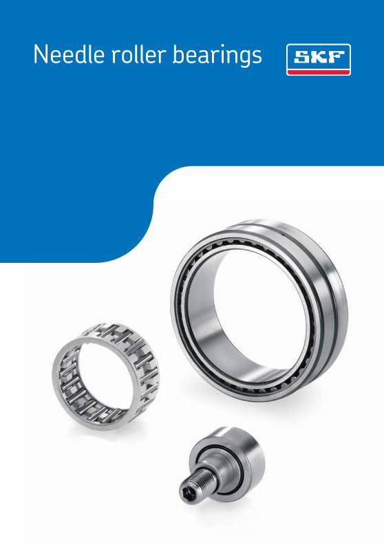
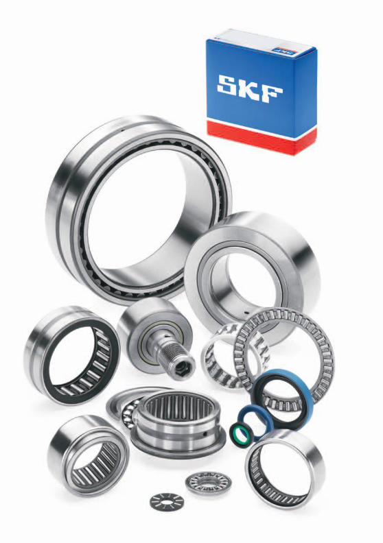
Needle roller bearings
® SKF is a registered trademark of the SKF Group.
© SKF Group 2015The contents of this publication are the copyright of the publisher and may not be reproduced (even extracts) unless prior written permission is granted. Every care has been taken to ensure the accuracy of the information contained in this publication but no liability can be accepted for any loss or damage whether direct, indirect or consequential arising out of the use of the information contained herein.
PUB PSD/P1 06003/2 EN · April 2015
Certain image(s) used under license from Shutterstock.com
Principles of bearing selection and application ............. 13
Needle roller and cage assemblies ............................... 57
Drawn cup needle roller bearings ................................ 75
Needle roller bearings with machined rings .................. 97
Alignment needle roller bearings ................................. 141
Needle roller thrust bearings and bearing washers ....... 151
Combined needle roller bearings .................................. 169
Needle roller bearing components ............................... 195
Track runner bearings ................................................. 215
1
9
8
7
6
5
4
3
2
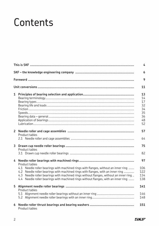
Contents
This is SKF ............................................................................................................ 4
SKF – the knowledge engineering company ............................................................. 6
Foreword .............................................................................................................. 9
Unit conversions .................................................................................................... 11
1 Principles of bearing selection and application ..................................................... 13Bearing terminology ................................................................................................................ 14Bearing types ........................................................................................................................... 17Bearing life and loads .............................................................................................................. 32Friction ..................................................................................................................................... 34Speeds ...................................................................................................................................... 35Bearing data – general ............................................................................................................ 36Application of bearings ............................................................................................................ 48Lubrication ............................................................................................................................... 52
2 Needle roller and cage assemblies ..................................................................... 57Product tables2.1 Needle roller and cage assemblies ................................................................................ 64
3 Drawn cup needle roller bearings ....................................................................... 75Product tables3.1 Drawn cup needle roller bearings ................................................................................. 82
4 Needle roller bearings with machined rings ......................................................... 97Product tables4.1 Needle roller bearings with machined rings with flanges, without an inner ring ....... 1064.2 Needle roller bearings with machined rings with flanges, with an inner ring ............. 1224.3 Needle roller bearings with machined rings without flanges, without an inner ring .. 1344.4 Needle roller bearings with machined rings without flanges, with an inner ring ....... 138
5 Alignment needle roller bearings ....................................................................... 141Product tables5.1 Alignment needle roller bearings without an inner ring ............................................... 1465.2 Alignment needle roller bearings with an inner ring ..................................................... 148
6 Needle roller thrust bearings and bearing washers .............................................. 151Product tables
2
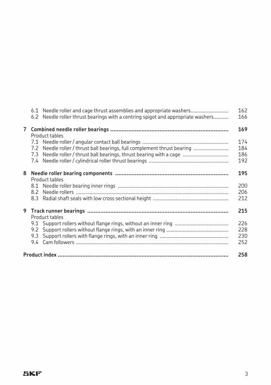
6.1 Needle roller and cage thrust assemblies and appropriate washers ............................ 1626.2 Needle roller thrust bearings with a centring spigot and appropriate washers ........... 166
7 Combined needle roller bearings ........................................................................ 169Product tables7.1 Needle roller / angular contact ball bearings ................................................................ 1747.2 Needle roller / thrust ball bearings, full complement thrust bearing .......................... 1847.3 Needle roller / thrust ball bearings, thrust bearing with a cage .................................. 1867.4 Needle roller / cylindrical roller thrust bearings ........................................................... 192
8 Needle roller bearing components ..................................................................... 195Product tables8.1 Needle roller bearing inner rings .................................................................................. 2008.2 Needle rollers ................................................................................................................. 2068.3 Radial shaft seals with low cross sectional height ........................................................ 212
9 Track runner bearings ...................................................................................... 215Product tables9.1 Support rollers without flange rings, without an inner ring ........................................ 2269.2 Support rollers without flange rings, with an inner ring .............................................. 2289.3 Support rollers with flange rings, with an inner ring ................................................... 2309.4 Cam followers ................................................................................................................. 252
Product index ........................................................................................................ 258
3
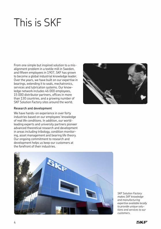
This is SKF
From one simple but inspired solution to a mis-alignment problem in a textile mill in Sweden, and fifteen employees in 1907, SKF has grown to become a global industrial knowledge leader. Over the years, we have built on our expertise in bearings, extending it to seals, mecha tronics, services and lubrication systems. Our know-ledge network includes 46 000 employees, 15 000 distributor partners, offices in more than 130 countries, and a growing number of SKF Solution Factory sites around the world.
Research and development We have hands-on experience in over forty industries based on our employees’ knowledge of real life conditions. In addition, our world-leading experts and university partners pioneer advanced theoretical research and development in areas including tribology, condition monitor-ing, asset management and bearing life theory. Our ongoing commitment to research and devel opment helps us keep our customers at the forefront of their industries.
SKF Solution Factory makes SKF knowledge and manu facturing expertise available locally to provide unique solu-tions and services to our customers.
4
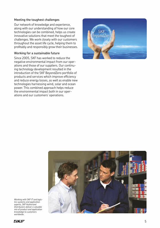
Meeting the toughest challenges Our network of knowledge and experience, along with our understanding of how our core technologies can be combined, helps us create innovative solutions that meet the toughest of challenges. We work closely with our customers throughout the asset life cycle, helping them to profitably and re spon sibly grow their businesses.
Working for a sustainable future Since 2005, SKF has worked to reduce the negative environmental impact from our operations and those of our suppliers. Our continuing technology development resulted in the introduction of the SKF BeyondZero portfolio of prod ucts and services which improve efficiency and reduce energy losses, as well as enable new technol ogies har nessing wind, solar and ocean power. This combined approach helps reduce the en vir on mental impact both in our operations and our customers’ oper ations.
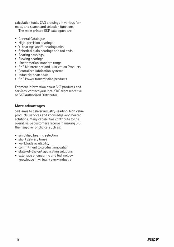
Working with SKF IT and logistics systems and application experts, SKF Authorized Distributors deliver a valuable mix of product and application knowledge to customers worldwide.
5

Our knowledge – your successSKF Life Cycle Management is how we combine our technology platforms and advanced ser vices, and apply them at each stage of the asset life cycle, to help our cus tomers to be more success ful, sustainable and profitable.
Working closely with you Our objective is to help our customers improve productivity, minimize main ten ance, achieve higher energy and resource efficiency, and optimize designs for long service life and reliability.
Innovative solutions Whether the application is linear or rotary or a combination, SKF engineers can work with you at each stage of the asset life cycle to improve machine performance by looking at the entire
application. This approach doesn’t just focus on individual components like bearings or seals. It looks at the whole application to see how each com po nent interacts with each other.
Design optimization and verificationSKF can work with you to optimize current or new designs with proprietary 3D mod ell ing software that can also be used as a virtual test rig to confirm the integrity of the design.
SKF – the knowledge engineering company
Spec
ifi catio
nDesign and develop
Manufacture and test
Install a
nd co
mm
issi
on
Operate and monitor
Maintain and repair
SKF Life Cycle Management
6
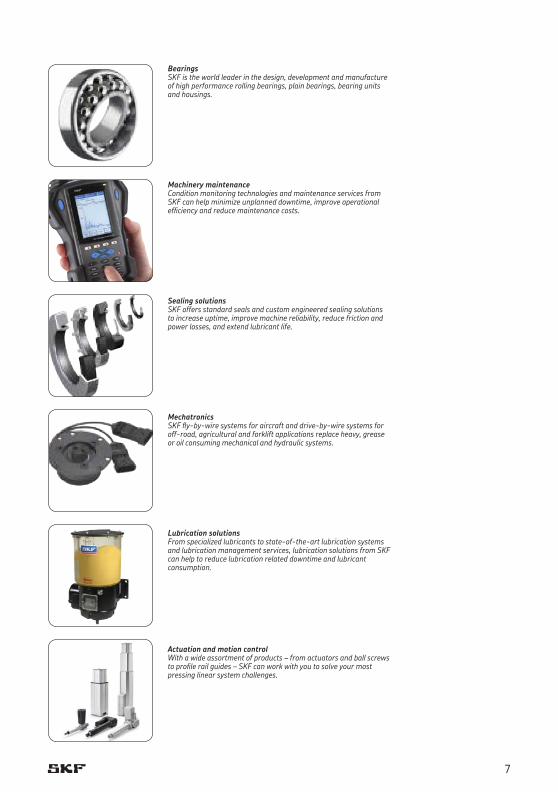
BearingsSKF is the world leader in the design, development and manufacture of high performance rolling bearings, plain bearings, bearing units and housings.
Machinery maintenanceCondition monitoring technologies and main tenance services from SKF can help minimize unplanned downtime, improve operational efficiency and reduce maintenance costs.
Sealing solutionsSKF offers standard seals and custom engineered sealing solutions to increase uptime, improve machine reliability, reduce friction and power losses, and extend lubricant life.
MechatronicsSKF flybywire systems for aircraft and drivebywire systems for offroad, agricultural and forklift applications replace heavy, grease or oil consuming mechanical and hydraulic systems.
Lubrication solutionsFrom specialized lubricants to stateoftheart lubrication systems and lubrication management ser vices, lubrication solutions from SKF can help to reduce lubrication related downtime and lubricant consumption.
Actuation and motion controlWith a wide assortment of products – from actu ators and ball screws to profile rail guides – SKF can work with you to solve your most pressing linear system challenges.
7

8
Foreword
Many bearing arrangements have limited radial space, but require bearings having a high load carrying capacity and a high degree of stiffness. SKF needle roller bearings with their low cross section fulfil these requirements. They also pro-vide an economical solution to these challenges if the shaft or housing bore can serve as raceways.
SKF track runner bearings are an excellent choice for all types of cam drives, tracks, con-veyor systems etc. where guidance is required.
For motorsport applications, SKF Racing has been using customized, high-performance needle roller bearings for many years. These special needle roller bearings are used in the most demanding Formula One applications, such as gearboxes. Using different advanced materials, coatings and designs, SKF’s advanced engineering knowledge can improve the per-formance and reliability of virtually any application.
SKF supplies needle roller bearings as well as track runner bearings in many designs, series and sizes, which make them appropriate for various operating conditions.
This catalogue presents the current standard assortment of SKF needle roller bearings, track runner bearings and radial shaft seals with low cross sectional height.
Structure of the catalogueThe catalogue starts with general product infor-mation followed by nine main chapters, which are marked with numbered blue tabs in the right margin:
• Chapter1providesbearingterminologyandtypes as well as selection, design and applica-tion recommendations.
• Chapters2to8describethevariousneedleroller bearing types and their associated com-ponents. Each chapter contains descriptions of the products as well as product tables, which list data for selecting a bearing and designing the bearing arrangement.• Similarly,chapter9presentsthevarious
designs and series of track runner bearings, incorporating needle or cylindrical rollers.
The index at the end lists all products presented in this catalogue in alphanumeric order.
About the data in this catalogueThe data in this catalogue relates to SKF’s state-of-the-art technology as of mid-2009. The data may differ from that shown in earlier catalogues because of revised methods of calculation, redesign or technological developments.
SKF reserves the right to make continuing improvements to SKF products with respect to materials, design and manufacturing methods, as well as changes necessitated by technological developments.
The units used in this catalogue are in accord-ance with ISO (International Organization for Standardization) standard 1000:1992, and SI (Système International d’Unités). A table for unit conversions can be found on page 7.
Other SKF cataloguesThe total SKF product portfolio is much broader than only needle roller bearings and track run-ner bearings. Product information is also avail-able via the SKF website at www.skf.com. The SKF Interactive Engineering Catalogue provides not only product information, but also online
9
calculation tools, CAD drawings in various for-mats, and search and selection functions.
The main printed SKF catalogues are:
• GeneralCatalogue• High-precisionbearings• Y-bearingsandY-bearingunits• Sphericalplainbearingsandrodends• Bearinghousings• Slewingbearings• Linearmotionstandardrange• SKFMaintenanceandLubricationProducts• Centralizedlubricationsystems• Industrialshaftseals• SKFPowertransmissionproducts
For more information about SKF products and services, contact your local SKF representative or SKF Authorized Distributor.
More advantagesSKF aims to deliver industry-leading, high value products, services and knowledge-engineered solutions. Many capabilities contribute to the overall value customers receive in making SKF their supplier of choice, such as:
• simplifiedbearingselection• shortdeliverytimes• worldwideavailability• commitmenttoproductinnovation• state-of-the-artapplicationsolutions• extensiveengineeringandtechnology
knowledge in virtually every industry
10
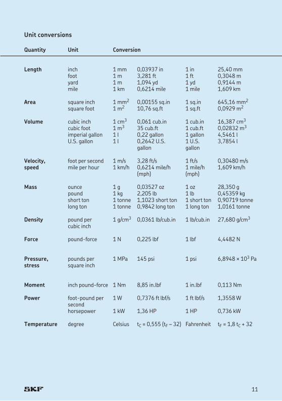
Unit conversions
Quantity Unit Conversion
Length inch 1 mm 0,03937 in 1 in 25,40 mm foot 1 m 3,281 ft 1 ft 0,3048 m yard 1 m 1,094 yd 1 yd 0,9144 m mile 1 km 0,6214 mile 1 mile 1,609 km
Area square inch 1 mm2 0,00155 sq.in 1 sq.in 645,16 mm2
square foot 1 m2 10,76 sq.ft 1 sq.ft 0,0929 m2
Volume cubic inch 1 cm3 0,061 cub.in 1 cub.in 16,387 cm3
cubic foot 1 m3 35 cub.ft 1 cub.ft 0,02832 m3
imperial gallon 1 l 0,22 gallon 1 gallon 4,5461 l U.S. gallon 1 l 0,2642 U.S. 1 U.S. 3,7854 l gallon gallon
Velocity, foot per second 1 m/s 3,28 ft/s 1 ft/s 0,30480 m/sspeed mile per hour 1 km/h 0,6214 mile/h 1 mile/h 1,609 km/h (mph) (mph)
Mass ounce 1 g 0,03527 oz 1 oz 28,350 g pound 1 kg 2,205 lb 1 lb 0,45359 kg short ton 1 tonne 1,1023 short ton 1 short ton 0,90719 tonne long ton 1 tonne 0,9842 long ton 1 long ton 1,0161 tonne
Density pound per 1 g/cm3 0,0361 lb/cub.in 1 lb/cub.in 27,680 g/cm3
cubic inch
Force pound-force 1 N 0,225 lbf 1 lbf 4,4482 N
Pressure, pounds per 1 MPa 145 psi 1 psi 6,8948 ¥ 103 Pastress square inch
Moment inch pound-force 1 Nm 8,85 in.lbf 1 in.lbf 0,113 Nm
Power foot-pound per 1 W 0,7376 ft lbf/s 1 ft lbf/s 1,3558 W second horsepower 1kW 1,36HP 1HP 0,736kW
Temperature degree Celsius tC = 0,555 (tF – 32) Fahrenheit tF = 1,8 tC + 32
11
Bearing terminology............................................................................................... 14
Bearing types ........................................................................................................ 17Needle roller bearings ................................................................................................................... 17Track runner bearings ................................................................................................................... 27
Bearing life and loads ............................................................................................. 32Bearing life ..................................................................................................................................... 32Equivalent bearing loads ............................................................................................................... 32Static bearing loads ....................................................................................................................... 32Requisite minimum load ............................................................................................................... 32
Friction ................................................................................................................. 34Estimating the frictional moment ................................................................................................. 34
Speeds .................................................................................................................. 35
Bearing data – general ........................................................................................... 36Tolerances ...................................................................................................................................... 36Internal clearance .......................................................................................................................... 42Cages .............................................................................................................................................. 43Seals ............................................................................................................................................... 43Materials ........................................................................................................................................ 43Supplementary designations ........................................................................................................ 46
Application of bearings ........................................................................................... 48Design of associated components ................................................................................................ 48Surface roughness of bearing seats ............................................................................................. 50Raceways on shafts and in housings ............................................................................................ 50
Lubrication ............................................................................................................ 52The SKF traffic light concept ......................................................................................................... 52Lubricating greases ....................................................................................................................... 53
Principles of bearing selection and application
13
1
Bearing terminology
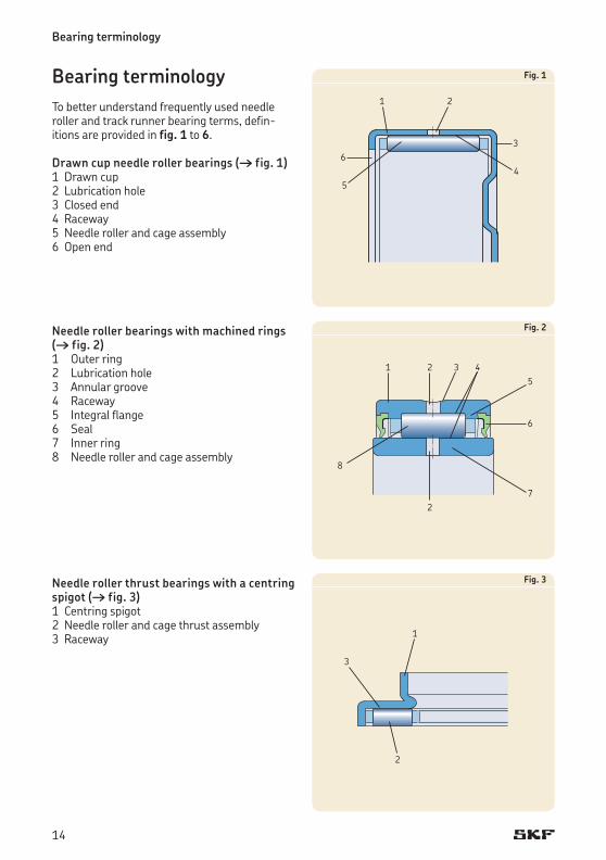
Bearing terminology To better understand frequently used needle roller and track runner bearing terms, defin-itions are provided in fig. 1 to 6.
Drawn cup needle roller bearings († fig. 1)1 Drawn cup2 Lubrication hole3 Closed end4 Raceway5 Needle roller and cage assembly6 Open end
Needle roller bearings with machined rings († fig. 2)1 Outer ring 2 Lubrication hole3 Annular groove4 Raceway5 Integral flange6 Seal7 Inner ring8 Needle roller and cage assembly
Needle roller thrust bearings with a centring spigot († fig. 3)1 Centring spigot2 Needle roller and cage thrust assembly3 Raceway
Fig. 1
Fig. 2
Fig. 3
1 2
5
64
3
1 25
6
43
8
27
1
2
3
14
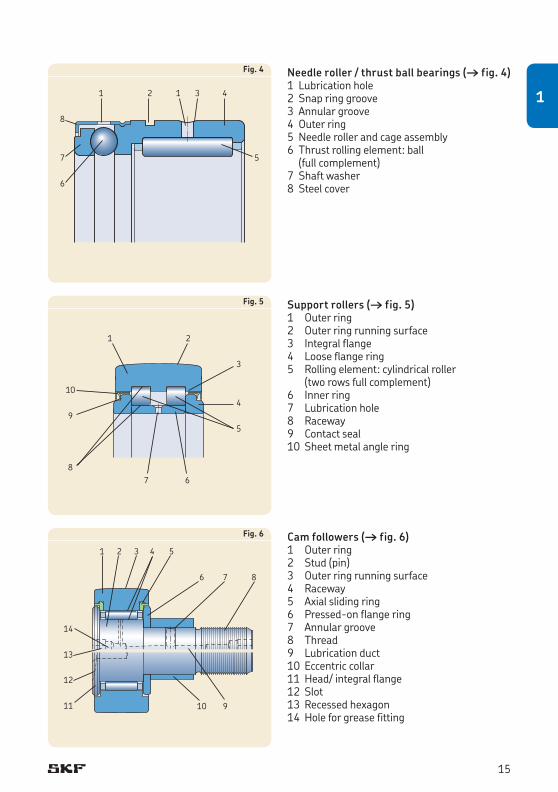
Needle roller / thrust ball bearings († fig. 4)1 Lubrication hole2 Snap ring groove3 Annular groove4 Outer ring5 Needle roller and cage assembly6 Thrust rolling element: ball
(full complement)7 Shaft washer8 Steel cover
Support rollers († fig. 5)1 Outer ring 2 Outer ring running surface3 Integral flange4 Loose flange ring5 Rolling element: cylindrical roller
(two rows full complement)6 Inner ring7 Lubrication hole8 Raceway9 Contact seal10 Sheet metal angle ring
Cam followers († fig. 6)1 Outer ring 2 Stud (pin)3 Outer ring running surface4 Raceway5 Axial sliding ring6 Pressed-on flange ring7 Annular groove8 Thread9 Lubrication duct10 Eccentric collar11Head/integralflange12 Slot13 Recessed hexagon14Holeforgreasefitting
Fig. 4
Fig. 5
Fig. 6
1 2
5
6
431
7
8
6
2
59
4
3
1
10
87
6
2 5
9
431
10
87
11
12
13
14
15
1
Bearing types
Needle roller bearingsNeedle roller bearings are bearings with cylin-drical rollers that are small in diameter. In spite of their low cross section, needle roller bearings have a high load carrying capacity and are therefore extremely suitable for bearing arrangements where radial space is limited.
SKF supplies needle roller bearings in differ-ent designs and in a wide range of sizes, which are appropriate for different applications. In addition to customized designs, they comprise the following types and components:
• needlerollerandcageassemblies• drawncupneedlerollerbearings• universaljointbearings• needlerollerbearingswithmachinedrings• alignmentneedlerollerbearings• needlerollerthrustbearings• bearingwashers• combinedneedlerollerbearings• needlerollerbearinginnerrings• needlerollers• radialshaftsealswithlowcrosssectional
height
Basic information about the different needle roller bearing types, washers, and seals is provided in the following overview.
17
1
Bearing types
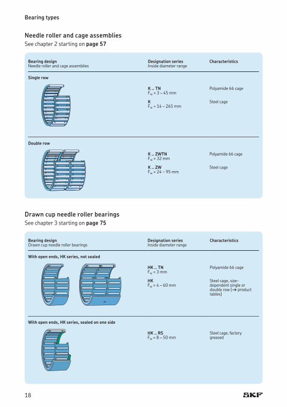
Needle roller and cage assembliesSee chapter 2 starting on page 57
Bearing designNeedle roller and cage assemblies
Designation series Inside diameter range
Characteristics
Single row
K .. TNFw = 3 – 45 mm
K Fw = 14 – 265 mm
Polyamide 66 cage
Steel cage
Double row
K .. ZWTNFw = 32 mm
K .. ZWFw = 24 – 95 mm
Polyamide 66 cage
Steel cage
Drawn cup needle roller bearingsSee chapter 3 starting on page 75
Bearing designDrawn cup needle roller bearings
Designation series Inside diameter range
Characteristics
With open ends, HK series, not sealed
HK .. TNFw = 3 mm
HK Fw = 4 – 60 mm
Polyamide 66 cage
Steel cage, size- dependent single or double row († product tables)
With open ends, HK series, sealed on one side
HK .. RSFw = 8 – 50 mm
Steel cage, factory greased
18
Bearing designDrawn cup needle roller bearings
Designation series Inside diameter range
Characteristics
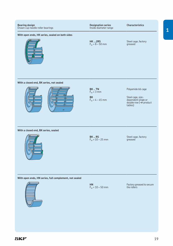
With open ends, HK series, sealed on both sides
HK ...2RSFw = 8 – 50 mm
Steel cage, factory greased
With a closed end, BK series, not sealed
BK .. TNFw = 3 mm
BK Fw = 4 – 45 mm
Polyamide 66 cage
Steel cage, size- dependent single or double row († product tables)
With a closed end, BK series, sealed
BK .. RSFw = 10 – 25 mm
Steel cage, factory greased
With open ends, HN series, full complement, not sealed
HN Fw = 10 – 50 mm
Factory greased to secure the rollers
19
1
Bearing types
Universal joint bearingsNot covered in this catalogue. For additional information, refer to the SKF Interactive Engineering Catalogue.
Needle roller bearings with machined ringsSee chapter 4 starting on page 97
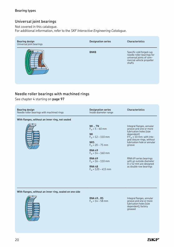
Bearing designUniversaljointbearings
Designation series Characteristics
BNKB Specific cold forged cup needle roller bearings for universaljointsofcom-mercial vehicle propeller shafts
Bearing designNeedle roller bearings with machined rings
Designation series Inside diameter range
Characteristics
With flanges, without an inner ring, not sealed
NK .. TNFw = 5 – 60 mm
NKFw = 12 – 110 mm
NKSFw = 20 – 75 mm
RNA 49Fw = 14 – 160 mm
RNA 69Fw = 16 – 110 mm
RNA 48 Fw = 120 – 415 mm
Integral flanges, annular groove and one or more lubrication holes (size dependent)If Fw ≤ 10 mm: with inte-gral closure rings, without lubrication hole or annular groove
RNA 69 series bearings with an outside diameter D ≥ 52 mm are designed as double row bearings
With flanges, without an inner ring, sealed on one side
RNA 49.. RSFw = 14 – 58 mm
Integral flanges, annular groove and one or more lubrication holes (size dependent), factory greased
20
Bearing designNeedle roller bearings with machined rings
Designation series Inside/bore diameter range
Characteristics
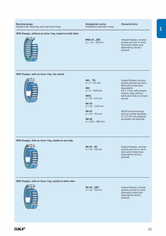
With flanges, without an inner ring, sealed on both sides
RNA 49...2RSFw = 14 – 58 mm
Integral flanges, annular groove and one or more lubrication holes (size dependent), factory greased
With flanges, with an inner ring, not sealed
NKI .. TNd = 5 – 55 mm
NKId = 9 – 100 mm
NKIS d = 15 – 65 mm
NA 49d = 10 – 140 mm
NA 69 d = 12 – 95 mm
NA 48d = 110 – 380 mm
Integral flanges, annular groove and one ore more lubrication holes (size dependent)If d ≤ 7 mm: with integral closure rings, without lubrication hole or annular groove
NA 69 series bearings with an outside diameter D ≥ 52 mm are designed as double row bearings
With flanges, with an inner ring, sealed on one side
NA 49.. RSd = 10 – 50 mm
Integral flanges, annular groove and one or more lubrication holes (size dependent), factory greased
With flanges, with an inner ring, sealed on both sides
NA 49...2RSd = 10 – 50 mm
Integral flanges, annular groove and one or more lubrication holes (size dependent), factory greased
21
1
Bearing types
Alignment needle roller bearingsSee chapter 5 starting on page 141
Bearing designNeedle roller bearings with machined rings
Designation series Inside/bore diameter range
Characteristics
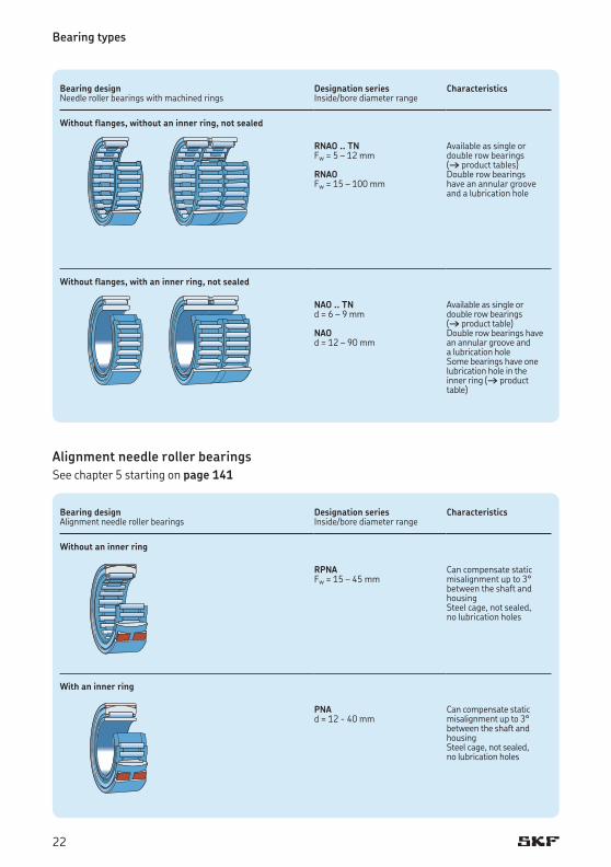
Without flanges, without an inner ring, not sealed
RNAO .. TNFw = 5 – 12 mm
RNAO Fw = 15 – 100 mm
Available as single or double row bearings († product tables)Double row bearings have an annular groove and a lubrication hole
Without flanges, with an inner ring, not sealed
NAO .. TNd = 6 – 9 mm
NAOd = 12 – 90 mm
Available as single or double row bearings († product table) Double row bearings have an annular groove and a lubrication holeSome bearings have one lubrication hole in the inner ring († product table)
Bearing designAlignment needle roller bearings
Designation series Inside/bore diameter range
Characteristics
Without an inner ring
RPNAFw = 15 – 45 mm
Can compensate static misalignment up to 3° between the shaft and housingSteel cage, not sealed, no lubrication holes
With an inner ring
PNAd = 12 - 40 mm
Can compensate static misalignment up to 3° between the shaft and housingSteel cage, not sealed, no lubrication holes
22
Bearing washersSee chapter 6 on page 154
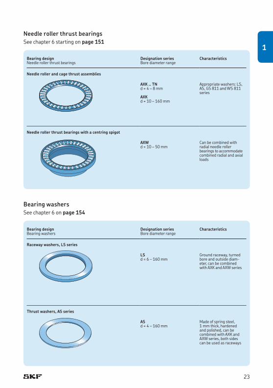
Needle roller thrust bearingsSee chapter 6 starting on page 151
Bearing designNeedle roller thrust bearings
Designation series Bore diameter range
Characteristics
Needle roller and cage thrust assemblies
AXK .. TNd = 4 – 8 mm
AXKd = 10 – 160 mm
Appropriate washers: LS, AS, GS 811 and WS 811 series
Needle roller thrust bearings with a centring spigot
AXWd = 10 – 50 mm
Can be combined with radial needle roller bearings to accommodate combined radial and axial loads
Bearing designBearing washers
Designation series Bore diameter range
Characteristics
Raceway washers, LS series
LSd = 6 – 160 mm
Ground raceway, turned bore and outside diam-eter, can be combined with AXK and AXW series
Thrust washers, AS series
ASd = 4 – 160 mm
Made of spring steel, 1 mm thick, hardened and polished, can be combined with AXK and AXW series, both sides can be used as raceways
LS
AS
23
1
Bearing types
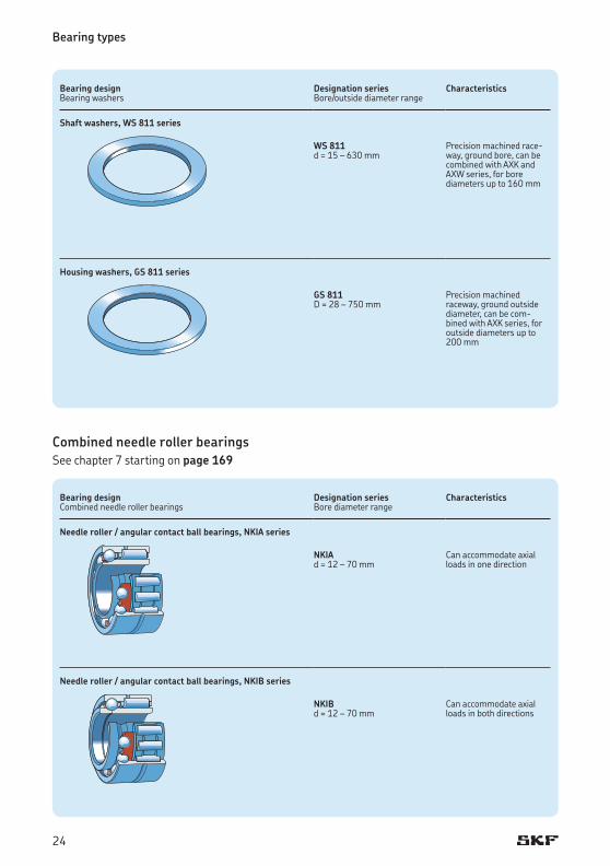
Combined needle roller bearingsSee chapter 7 starting on page 169
Bearing designBearing washers
Designation series Bore/outside diameter range
Characteristics
Shaft washers, WS 811 series
WS 811d = 15 – 630 mm
Precision machined race-way, ground bore, can be combined with AXK and AXW series, for bore diameters up to 160 mm
Housing washers, GS 811 series
GS 811D = 28 – 750 mm
Precision machined raceway, ground outside diameter, can be com-bined with AXK series, for outside diameters up to 200 mm
Bearing designCombined needle roller bearings
Designation series Bore diameter range
Characteristics
Needle roller / angular contact ball bearings, NKIA series
NKIAd = 12 – 70 mm
Can accommodate axial loads in one direction
Needle roller / angular contact ball bearings, NKIB series
NKIBd = 12 – 70 mm
Can accommodate axial loads in both directions
GS
WS
24
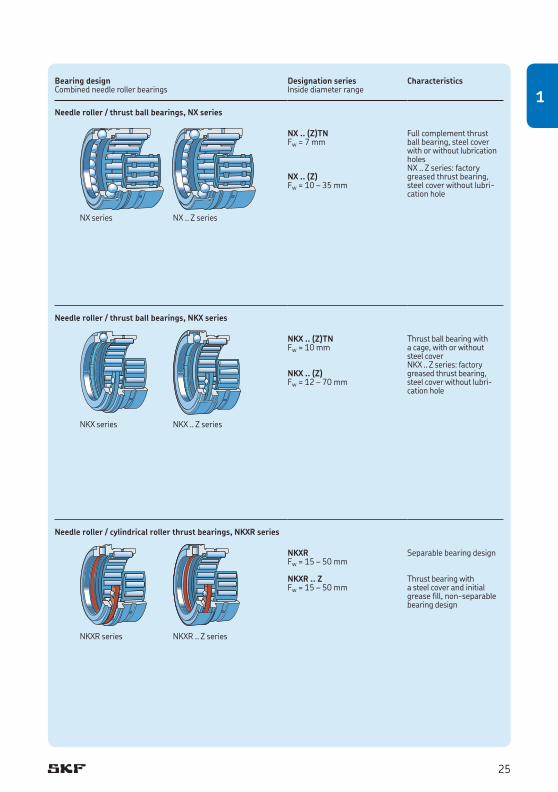
Bearing designCombined needle roller bearings
Designation series Inside diameter range
Characteristics
Needle roller / thrust ball bearings, NX series
NX .. (Z)TNFw = 7 mm
NX .. (Z)Fw = 10 – 35 mm
Full complement thrust ball bearing, steel cover with or without lubrication holesNX .. Z series: factory greased thrust bearing, steel cover without lubri-cation hole
Needle roller / thrust ball bearings, NKX series
NKX .. (Z)TNFw = 10 mm
NKX .. (Z)Fw = 12 – 70 mm
Thrust ball bearing with a cage, with or without steel cover NKX .. Z series: factory greased thrust bearing, steel cover without lubri-cation hole
Needle roller / cylindrical roller thrust bearings, NKXR series
NKXRFw = 15 – 50 mm
NKXR .. ZFw = 15 – 50 mm
Separable bearing design
Thrust bearing with a steel cover and initial grease fill, non-separable bearing design
NKX series NKX .. Z series
NKXR series NKXR .. Z series
NX series NX .. Z series
25
1
Bearing types
Radial shaft seals with a low cross sectional heightSee chapter 8 on page 208
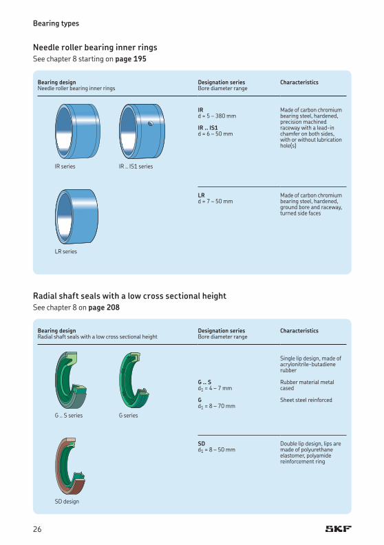
Needle roller bearing inner ringsSee chapter 8 starting on page 195
Bearing designNeedle roller bearing inner rings
Designation series Bore diameter range
Characteristics
IRd = 5 – 380 mm
IR .. IS1d = 6 – 50 mm
Made of carbon chromium bearing steel, hardened, precision machined raceway with a lead-in chamfer on both sides, with or without lubrication hole(s)
LRd = 7 – 50 mm
Made of carbon chromium bearing steel, hardened, ground bore and raceway, turned side faces
IR series IR .. IS1 series
LR series
Bearing designRadial shaft seals with a low cross sectional height
Designation series Bore diameter range
Characteristics
G .. Sd1 = 4 – 7 mm
Gd1 = 8 – 70 mm
Single lip design, made of acrylonitrile-butadiene rubber
Rubber material metal cased
Sheet steel reinforced
SDd1 = 8 – 50 mm
Double lip design, lips are made of polyurethane elastomer, polyamide reinforcement ring
G .. S series G series
SD design
26
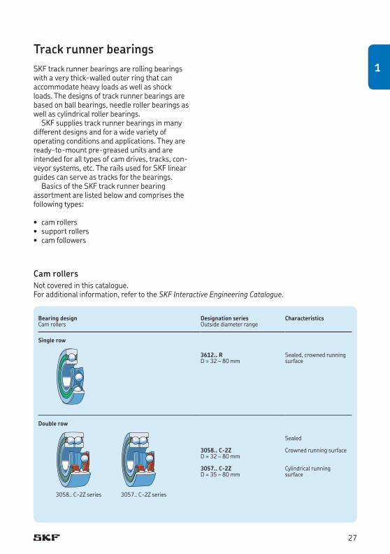
Track runner bearingsSKF track runner bearings are rolling bearings with a very thick-walled outer ring that can accommodate heavy loads as well as shock loads. The designs of track runner bearings are based on ball bearings, needle roller bearings as well as cylindrical roller bearings.
SKF supplies track runner bearings in many different designs and for a wide variety of operating conditions and applications. They are ready-to-mount pre-greased units and are intended for all types of cam drives, tracks, con-veyor systems, etc. The rails used for SKF linear guides can serve as tracks for the bearings.
Basics of the SKF track runner bearing assortment are listed below and comprises the following types:
• camrollers• supportrollers• camfollowers
Cam rollersNot covered in this catalogue. For additional information, refer to the SKF Interactive Engineering Catalogue.
Bearing designCam rollers
Designation series Outside diameter range
Characteristics
Single row
3612.. RD = 32 – 80 mm
Sealed, crowned running surface
Double row
3058.. C-2ZD = 32 – 80 mm
3057.. C-2ZD = 35 – 80 mm
Sealed
Crowned running surface
Cylindrical running surface
3058.. C-2Z series 3057.. C-2Z series
27
1
Bearing types
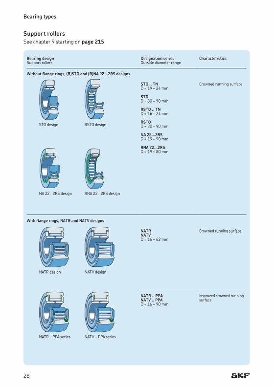
Support rollersSee chapter 9 starting on page 215
Bearing designSupport rollers
Designation series Outside diameter range
Characteristics
Without flange rings, (R)STO and (R)NA 22...2RS designs
STO .. TND = 19 – 24 mm
STO D = 30 – 90 mm
RSTO .. TND = 16 – 24 mm
RSTO D = 30 – 90 mm
NA 22…2RSD = 19 – 90 mm
RNA 22…2RSD = 19 – 80 mm
Crowned running surface
With flange rings, NATR and NATV designs
NATR NATVD = 16 – 62 mm
Crowned running surface
NATR .. PPANATV .. PPAD = 16 – 90 mm
Improved crowned running surface
STO design RSTO design
NA 22…2RS design RNA 22…2RS design
NATR design NATV design
NATR .. PPA series NATV .. PPA series
28
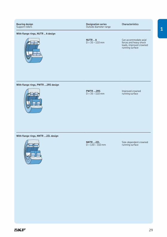
Bearing designSupport rollers
Designation series Outside diameter range
Characteristics
With flange rings, NUTR .. A design
NUTR .. AD = 35 – 110 mm
Can accommodate axial forces and heavy shock loads, improved crowned running surface
With flange rings, PWTR ...2RS design
PWTR ...2RSD = 35 – 110 mm
Improved crowned running surface
With flange rings, NNTR ...2ZL design
NNTR ...2ZLD = 130 – 310 mm
Size-dependent crowned running surface
29
1
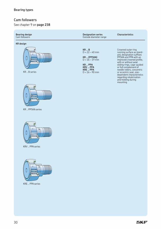
Bearing designCam followers
Designation series Outside diameter range
Characteristics
KR design
KR .. BD = 22 – 40 mm
KR .. (PPSKA)D = 16 – 19 mm
KR .. PPAKRV .. PPAKRE .. PPAD = 16 – 90 mm
Crowned outer ring running surface as stand-ard, designation suffixes PPSKA and PPA with an improved crowned profile, with or without axial sliding rings, cage-guided or full complement of needle rollers, concentric or eccentric seat, size-dependent characteristics regarding relubrication and holding during mounting
Bearing types
Cam followersSee chapter 9 on page 238
KR .. B series
KR .. PPSKA series
KRV .. PPA series
KRE .. PPA series
30
Bearing designCam followers
Designation series Outside diameter range
Characteristics
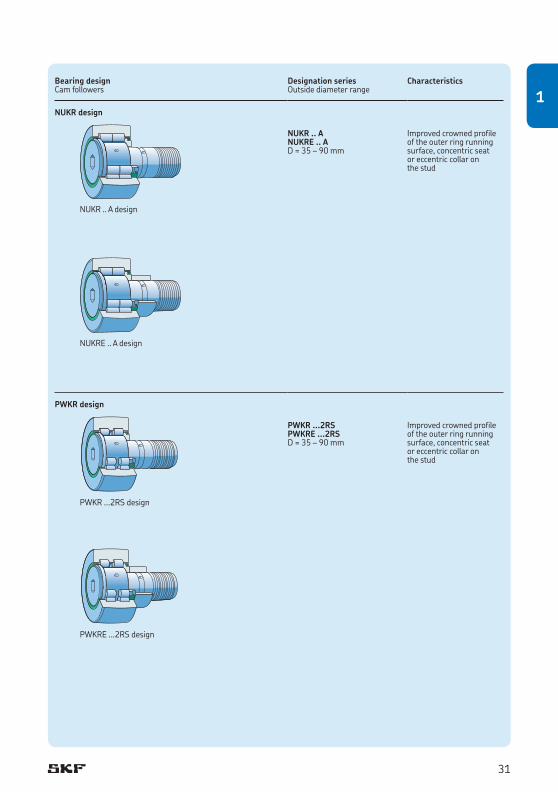
NUKR design
NUKR .. ANUKRE .. AD = 35 – 90 mm
Improved crowned profile of the outer ring running surface, concentric seat or eccentric collar on the stud
PWKR design
PWKR ...2RSPWKRE ...2RSD = 35 – 90 mm
Improved crowned profile of the outer ring running surface, concentric seat or eccentric collar on the stud
NUKR .. A design
NUKRE .. A design
PWKR ...2RS design
PWKRE ...2RS design
31
1
Bearing life and loads
Bearing lifeThe bearing size to be used can be selected on the basis of its load ratings in relation to the applied loads and the requirements regarding bearing life and reliability. A simple way to calcu-late bearing life is the classic ISO formula for basicratinglife.However,SKFrecommendsusing the SKF rating life, which makes predicting bearing life more reliable.
The values of the basic dynamic load rating C and the basic static load rating C0 are listed in the product tables.
For additional information about the calcula-tion methods and the equations, refer to the SKF General Catalogue. Calculations can also be performed easily online using the SKF Interactive Engineering Catalogue, available online at www.skf.com.
The general information about bearing life calculations and basic load ratings provided in the SKF General Catalogue and in the SKF Interactive Engineering Catalogue are also valid for needle roller bearings.
Equivalent bearing loadsNeedle roller bearings can accommodate either radial loads (radial bearings) or axial loads (thrust bearings). Therefore, the equivalent bearing load P is equal to the calculated bearing load F and can be inserted directly into the life equations.
Combined needle roller bearingsThe equation P = F is also valid for the radial and thrust bearing of combined needle roller bear-ings. It is necessary to calculate the life of the
radial needle roller bearing and the thrust bear-ing separately.
For needle roller / angular contact ball bear-ings, the axial component of the load Fa must not exceed 25% of the radial component of the load Fr.
The values of the basic load ratings C for the radial and axial bearings are listed separately in the product tables.
Static bearing loadsThe basic static load rating C0 is used in calcula-tions when the bearings are to:
• rotateatveryslowspeeds(n < 10 r/min)• performveryslowoscillatingmovements• bestationaryunderloadforextendedperiods• beundershockorheavypeakloads,whether
it is rotating (dynamically stressed) or at rest
If one of these conditions exists, refer to the SKF General Catalogue (section Selection of bearing size).
Requisite minimum loadThe correlation between load and service life is lessimportantwhenbearingsaresubjectedtovery light loads, because the failure mode is typic ally something other than fatigue.
To achieve satisfactory operation, needle roller and track runner bearings must always be sub-jectedtoarequisiteminimumload.Applyinga requisite minimum load is especially important for bearings that operate at high speeds or are subjectedtohighaccelerationsorrapidchangesin the direction of load. Under these conditions, not applying the correct minimum load can
32
result in damaging sliding movement between the rollers and raceways caused by the inertia forces of the needle rollers and cage and friction in the lubricant.
The requisite minimum radial and axial loads to be applied can be estimated for:
• radialneedlerollerbearingsusing Frm = 0,02 C
• needlerollerthrustbearingsusing Fam = 0,0005 C0
• trackrunnerbearingsusing Frm = 0,0167 C0
The requisite minimum axial load for the thrust part of combined bearings can be obtained for:
• angularcontactballbearingsusing C0 q n dm w2 Fam = 0,25 ––––– –––––––– 1 000 < 100 000 z
• cylindricalrollerthrustbearingsusing
q n w2 Fam = 0,0005 C0 + A –––––– < 1 000 z
• thrustballbearingsusing
q n w2 Fam = A –––––– < 1 000 z
whereFrm = minimum radial load [kN]Fam = minimum axial load [kN]C = basic dynamic load rating
(† product tables) [kN]C0 = basic static load rating
(† product tables) [kN]dm = mean bearing diameter = 0,5 (d + D) [mm]n = rotational speed [r/min]A = minimum load factor († product tables)
When starting up at low temperatures or when the lubricant is highly viscous, an even greater minimumloadmayberequired.However,theweight of the components supported by the bearing, together with the external forces, generally exceeds the requisite minimum load. If this is not the case, the bearing must be sub-jectedtoanadditionalradialand/oraxialload.
33
1
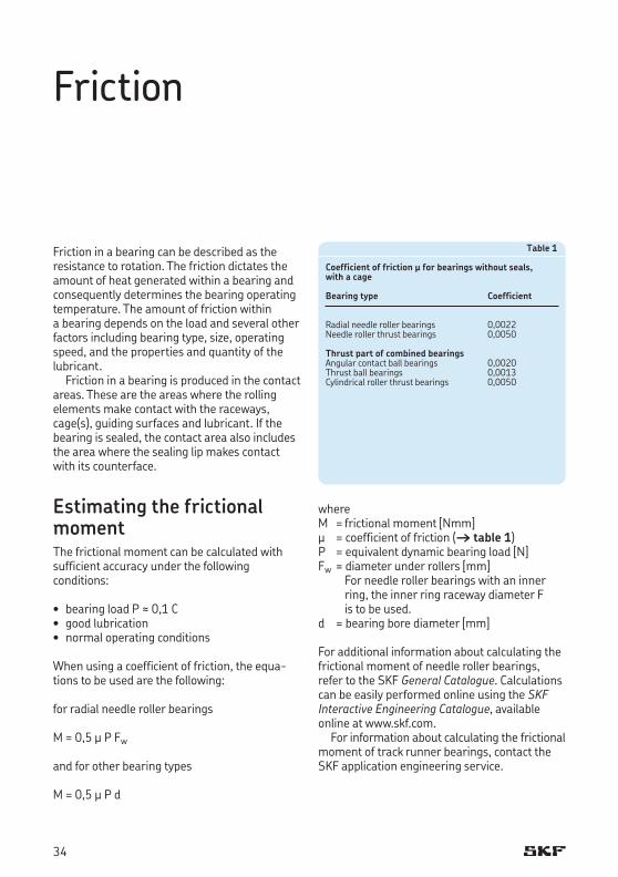
Table 1
Coefficient of friction µ for bearings without seals,with a cage
Bearing type Coefficient
Radial needle roller bearings 0,0022Needle roller thrust bearings 0,0050
Thrust part of combined bearingsAngular contact ball bearings 0,0020Thrust ball bearings 0,0013Cylindrical roller thrust bearings 0,0050
Friction
Friction in a bearing can be described as the resistance to rotation. The friction dictates the amount of heat generated within a bearing and consequently determines the bearing operating temperature. The amount of friction within a bearing depends on the load and several other factors including bearing type, size, operating speed, and the properties and quantity of the lubricant.
Friction in a bearing is produced in the contact areas. These are the areas where the rolling elem ents make contact with the raceways, cage(s), guiding surfaces and lubricant. If the bearing is sealed, the contact area also includes the area where the sealing lip makes contact with its counterface.
Estimating the frictional momentThe frictional moment can be calculated with sufficient accuracy under the following conditions:
• bearingloadP ≈ 0,1 C• goodlubrication• normaloperatingconditions
When using a coefficient of friction, the equa-tions to be used are the following:
for radial needle roller bearings
M = 0,5 μ P Fw
and for other bearing types
M = 0,5 μ P d
whereM = frictional moment [Nmm] μ = coefficient of friction († table 1) P = equivalent dynamic bearing load [N]Fw = diameter under rollers [mm]
For needle roller bearings with an inner ring, the inner ring raceway diameter F is to be used.
d = bearing bore diameter [mm]
For additional information about calculating the frictional moment of needle roller bearings, refer to the SKF General Catalogue. Calculations can be easily performed online using the SKF Interactive Engineering Catalogue, available online at www.skf.com.
For information about calculating the frictional moment of track runner bearings, contact the SKF application engineering service.
34
Speeds
In the product tables, two speeds are typically listed: reference speed and limiting speed.
The reference speed represents the speed, under specific operating conditions, at which there is equilibrium between the heat that is generated by the bearing and the heat that is dissipated from the bearing via the shaft, hous-ing and lubricant.
Limiting speed is determined by criteria that include the form stability or strength of the cage, lubrication of cage guiding surfaces, centri fugal and gyratory forces acting on the rolling elements, precision and other speed-limiting factors such as seals and lubricant for sealed bearings.
Which of these two speed values to consider depends on the needs of the application. In certain applications, such as very low speeds or oscillating movements, the speed limits are superseded in importance by other considerations.
For certain bearings, where the speed limit is not determined by heat from the rolling elem-ents/raceway contacts, only limiting speeds are listed in the product tables. These include, for example, bearings with contact seals and all track runner bearings.
For additional information about speeds and calculations, refer to the SKF General Catalogue (section Speeds and vibration).
35
1
Bearing data – general
SKF needle roller bearings are manufactured to several specifications. These specifications, con-cerning tolerances and internal clearance, are described in the following sections. Information about each bearing type is provided in the intro-ductory text of the individual product chapters.
TolerancesUnless otherwise stated, the needle roller bear-ings listed in this catalogue are manufactured to dimensional, form and running accuracy of needle roller bearings in accordance with the following international standards:
• ISO 199:2005: Rolling bearings – Thrust bearings – Tolerances• ISO 492:2002: Rolling bearings –
Radial bearings – Tolerances
Information about the bearing types and the relevant tolerance classes are provided in the introductory text of the individual product chapters as well as tolerances for the inside diameter Fw of the roller set. Actual tolerance values are listed in tables 2 to 5 on pages 38 to 41. The tolerance symbols used there are listed together with their definitions in table 1.
36
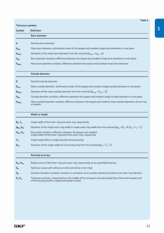
Table 1
Tolerance symbols
Symbol Definition
Bore diameter
d Nominal bore diameter
dmp Mean bore diameter, arithmetical mean of the largest and smallest single bore diameters in one plane
Δdmp Deviation of the mean bore diameter from the nominal (Δdmp = dmp – d)
Vdp Bore diameter variation; difference between the largest and smallest single bore diameters in one plane
Vdmp Mean bore diameter variation; difference between the largest and smallest mean bore diameter
Outside diameter
D Nominal outside diameter
Dmp Mean outside diameter; arithmetical mean of the largest and smallest single outside diameters in one plane
ΔDmp Deviation of the mean outside diameter from the nominal (ΔDmp = Dmp – D)
VDp Outside diameter variation; difference between the largest and smallest single outside diameters in one plane
VDmp Mean outside diameter variation; difference between the largest and smallest mean outside diameters of one ring or washer
Width or height
Bs, Cs Single width of the inner ring and outer ring, respectively
ΔBs, ΔCs Deviation of the single inner ring width or single outer ring width from the nominal (ΔBs = Bs – B; ΔCs = Cs – C)
VBs, VCs Ring width variation; difference between the largest and smallest single widths of the inner ring and of the outer ring, respectively
TS Singleheight(H)ofasingledirectionthrustbearing
ΔTs Deviation of the single height of a thrust bearing from the nominal (ΔTs = TS – T)
Running accuracy
Kia, Kea Radial runout of the inner ring and outer ring, respectively, of an assembled bearing
Sd Side face runout with reference to the bore (of an inner ring)
SD Outside inclination variation; variation in inclination of an outside cylindrical surface to an outer ring side face
Si, Se Thickness variation, measured from the middle of the raceway to the back (seat) face of the shaft washer and of the housing washer, respectively (axial runout)
37
1
Bearing data – general
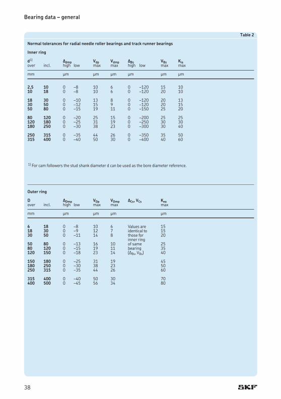
Table 2
Normal tolerances for radial needle roller bearings and track runner bearings
Inner ring d1) Δdmp Vdp Vdmp ΔBs VBs Kiaover incl. high low max max high low max max
mm μm μm μm μm μm μm
2,5 10 0 –8 10 6 0 –120 15 1010 18 0 –8 10 6 0 –120 20 10
18 30 0 –10 13 8 0 –120 20 1330 50 0 –12 15 9 0 –120 20 1550 80 0 –15 19 11 0 –150 25 20
80 120 0 –20 25 15 0 –200 25 25120 180 0 –25 31 19 0 –250 30 30180 250 0 –30 38 23 0 –300 30 40
250 315 0 –35 44 26 0 –350 35 50315 400 0 –40 50 30 0 –400 40 60
1) For cam followers the stud shank diameter d can be used as the bore diameter reference.
Outer ring
D ΔDmp VDp VDmp ΔCs, VCs Keaover incl. high low max max max
mm μm μm μm μm
6 18 0 –8 10 6 Values are 1518 30 0 –9 12 7 identical to 1530 50 0 –11 14 8 those for 20 inner ring 50 80 0 –13 16 10 of same 2580 120 0 –15 19 11 bearing 35120 150 0 –18 23 14 (ΔBs, VBs) 40
150 180 0 –25 31 19 45180 250 0 –30 38 23 50250 315 0 –35 44 26 60
315 400 0 –40 50 30 70400 500 0 –45 56 34 80
38
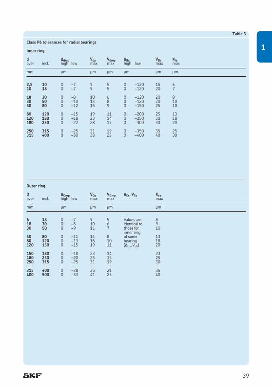
Table 3
Class P6 tolerances for radial bearings
Inner ring d Δdmp Vdp Vdmp ΔBs VBs Kiaover incl. high low max max high low max max
mm μm μm μm μm μm μm
2,5 10 0 –7 9 5 0 –120 15 610 18 0 –7 9 5 0 –120 20 7 18 30 0 –8 10 6 0 –120 20 830 50 0 –10 13 8 0 –120 20 1050 80 0 –12 15 9 0 –150 25 10 80 120 0 –15 19 11 0 –200 25 13120 180 0 –18 23 14 0 –250 30 18180 250 0 –22 28 17 0 –300 30 20 250 315 0 –25 31 19 0 –350 35 25315 400 0 –30 38 23 0 –400 40 30
Outer ring D ΔDmp VDp VDmp ΔCs, VCs Keaover incl. high low max max max
mm μm μm μm μm
6 18 0 –7 9 5 Values are 818 30 0 –8 10 6 identical to 930 50 0 –9 11 7 those for 10 inner ring 50 80 0 –11 14 8 of same 1380 120 0 –13 16 10 bearing 18120 150 0 –15 19 11 (ΔBs, VBs) 20
150 180 0 –18 23 14 23180 250 0 –20 25 15 25250 315 0 –25 31 19 30
315 400 0 –28 35 21 35400 500 0 –33 41 25 40
39
1
Bearing data – general
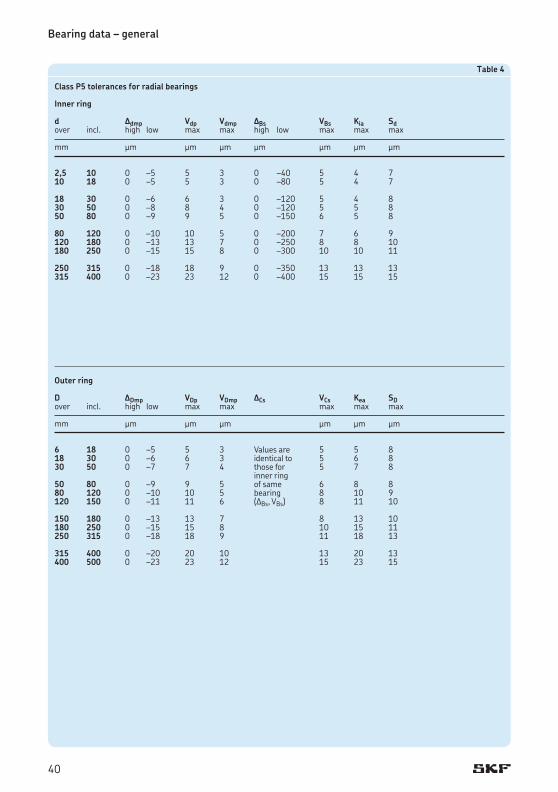
Table 4
Class P5 tolerances for radial bearings
Inner ring d Δdmp Vdp Vdmp ΔBs VBs Kia Sdover incl. high low max max high low max max max
mm μm μm μm μm μm μm μm
2,5 10 0 –5 5 3 0 –40 5 4 710 18 0 –5 5 3 0 –80 5 4 7 18 30 0 –6 6 3 0 –120 5 4 830 50 0 –8 8 4 0 –120 5 5 850 80 0 –9 9 5 0 –150 6 5 8 80 120 0 –10 10 5 0 –200 7 6 9120 180 0 –13 13 7 0 –250 8 8 10180 250 0 –15 15 8 0 –300 10 10 11 250 315 0 –18 18 9 0 –350 13 13 13315 400 0 –23 23 12 0 –400 15 15 15
Outer ring
D ΔDmp VDp VDmp ΔCs VCs Kea SDover incl. high low max max max max max
mm μm μm μm μm μm μm
6 18 0 –5 5 3 Values are 5 5 818 30 0 –6 6 3 identical to 5 6 830 50 0 –7 7 4 those for 5 7 8 inner ring 50 80 0 –9 9 5 of same 6 8 880 120 0 –10 10 5 bearing 8 10 9120 150 0 –11 11 6 (ΔBs, VBs) 8 11 10 150 180 0 –13 13 7 8 13 10180 250 0 –15 15 8 10 15 11250 315 0 –18 18 9 11 18 13 315 400 0 –20 20 10 13 20 13400 500 0 –23 23 12 15 23 15
40
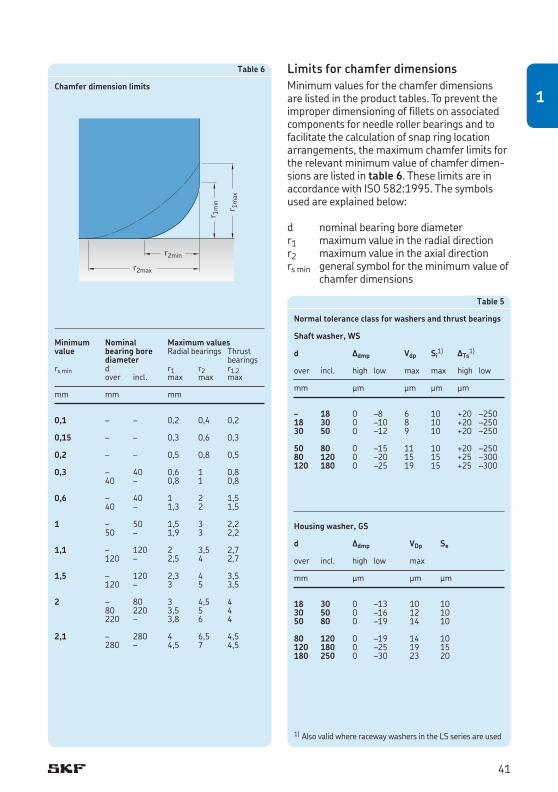
Limits for chamfer dimensionsMinimum values for the chamfer dimensions are listed in the product tables. To prevent the improper dimensioning of fillets on associated components for needle roller bearings and to facilitate the calculation of snap ring location arrangements, the maximum chamfer limits for the relevant minimum value of chamfer dimen-sions are listed in table 6. These limits are in accordance with ISO 582:1995. The symbols used are explained below:
d nominal bearing bore diameterr1 maximum value in the radial directionr2 maximum value in the axial directionrs min general symbol for the minimum value of
chamfer dimensions
Table 6
Chamfer dimension limits
Minimum Nominal Maximum valuesvalue bearing bore Radial bearings Thrust diameter bearingsrs min d r1 r2 r1,2 over incl. max max max
mm mm mm
0,1 – – 0,2 0,4 0,2
0,15 – – 0,3 0,6 0,3
0,2 – – 0,5 0,8 0,5
0,3 – 40 0,6 1 0,8 40 – 0,8 1 0,8
0,6 – 40 1 2 1,5 40 – 1,3 2 1,5
1 – 50 1,5 3 2,2 50 – 1,9 3 2,2
1,1 – 120 2 3,5 2,7 120 – 2,5 4 2,7
1,5 – 120 2,3 4 3,5 120 – 3 5 3,5
2 – 80 3 4,5 4 80 220 3,5 5 4 220 – 3,8 6 4
2,1 – 280 4 6,5 4,5 280 – 4,5 7 4,5
r2min
r2max
r 1m
in
r 1m
ax
Table 5
Normal tolerance class for washers and thrust bearings
Shaft washer, WS
d Δdmp Vdp Si1) ΔTs
1)
over incl. high low max max high low
mm μm μm μm μm
– 18 0 –8 6 10 +20 –25018 30 0 –10 8 10 +20 –25030 50 0 –12 9 10 +20 –250
50 80 0 –15 11 10 +20 –25080 120 0 –20 15 15 +25 –300120 180 0 –25 19 15 +25 –300
Housing washer, GS
d Δdmp VDp Se
over incl. high low max
mm μm μm μm
18 30 0 –13 10 1030 50 0 –16 12 1050 80 0 –19 14 10 80 120 0 –19 14 10120 180 0 –25 19 15180 250 0 –30 23 20
1) Also valid where raceway washers in the LS series are used
41
1
Bearing data – general
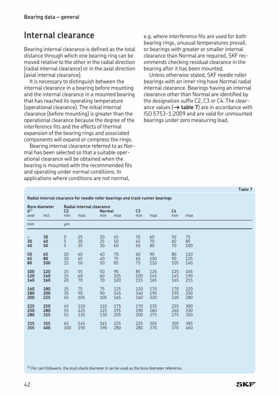
Internal clearanceBearing internal clearance is defined as the total distance through which one bearing ring can be moved relative to the other in the radial direction (radial internal clearance) or in the axial direction (axial internal clearance).
It is necessary to distinguish between the internal clearance in a bearing before mounting and the internal clearance in a mounted bearing that has reached its operating temperature (operational clearance). The initial internal clearance (before mounting) is greater than the operational clearance because the degree of the interference fits and the effects of thermal expansion of the bearing rings and associated components will expand or compress the rings.
Bearing internal clearance referred to as Nor-mal has been selected so that a suitable oper-ational clearance will be obtained when the bearing is mounted with the recommended fits and operating under normal conditions. In applications where conditions are not normal,
e.g. where interference fits are used for both bearing rings, unusual temperatures prevail, or bearings with greater or smaller internal clearance than Normal are required, SKF rec-ommends checking residual clearance in the bearing after it has been mounted.
Unless otherwise stated, SKF needle roller bearings with an inner ring have Normal radial internal clearance. Bearings having an internal clearance other than Normal are identified by the designation suffix C2, C3 or C4. The clear-ance values († table 7) are in accordance with ISO 5753-1:2009 and are valid for unmounted bearings under zero measuring load.
Table 7
Radial internal clearance for needle roller bearings and track runner bearings
Bore diameter Radial internal clearance d1) C2 Normal C3 C4 over incl. min max min max min max min max
mm μm
– 30 0 25 20 45 35 60 50 7530 40 5 30 25 50 45 70 60 8540 50 5 35 30 60 50 80 70 100
50 65 10 40 40 70 60 90 80 11065 80 10 45 40 75 65 100 90 12580 100 15 50 50 85 75 110 105 140
100 120 15 55 50 90 85 125 125 165120 140 15 60 60 105 100 145 145 190140 160 20 70 70 120 115 165 165 215
160 180 25 75 75 125 120 170 170 220180 200 35 90 90 145 140 195 195 250200 225 45 105 105 165 160 220 220 280
225 250 45 110 110 175 170 235 235 300250 280 55 125 125 195 190 260 260 330280 315 55 130 130 205 200 275 275 350
315 355 65 145 145 225 225 305 305 385355 400 100 190 190 280 280 370 370 460
1) For cam followers, the stud shank diameter d can be used as the bore diameter reference.
42
CagesBearing cages can influence the suitability of a rolling bearing for a particular application. Their main purposes are:
• toseparatetherollingelementsandkeepthemspaced evenly for uniform load distribution• toreducenoiselevels• toguidetherollingelementsintheunloaded
zone to improve rolling conditions and pre-vent damaging sliding movements• toretaintherollingelementswhenmounting
separable bearings
Cages are stressed by friction, inertia forces and heat. Depending on the material, cages can also be affected by certain lubricants, lubricant addi-tives, organic solvents, coolants, or by-products of these substances as they age. Therefore, cage design and material are of paramount import-ance for the performance and the operational reliability of the bearing.
For larger bearings, the standard cage may be different than the one used in smaller bearings even though they are in the same design or series. In the introductory text of each product chapter, information is provided about standard cages.
SealsThe seals integrated in a needle roller bearing can have a considerable impact on the perform-ance and reliability of the bearing. Their primary purpose is to exclude solid contaminants and moisture and retain the lubricant in the bearing. The seal materials must withstand oxidation and offer excellent thermal or chemical resist-ance. Integral seals are generally contact seals or sliding rings.
Depending on the internal geometry and design of the bearing, the arrangement of the bearing and associated components can form non-contact seals and act as efficient labyrinth or gap-type seals.
Additional information about seals is available in the introductory text of each product chapter, if seals are available.
In addition to integral bearing seals, SKF also supplies an assortment of radial shaft seals that can be used as external seals. Appropriate seals are listed in the product tables, if available. For
additional information, refer to the section Radial shaft seals with a low cross sectional height, starting on page 208.
MaterialsThe material used to make a bearing component determines, to a large extent, the performance and reliability of that bearing. For the bearing rings and rolling elements, typical considerations include hardness for load carrying capacity, fatigue resistance under rolling contact condi-tions, under clean or contaminated lubrication conditions, and the dimensional stability of the bearing components.
For additional information about seal materials, refer to the SKF General Catalogue. The general information about materials also applies to needle roller bearings.
Materials for bearing rings and rolling elementsThe standard steel used to produce machined rings and rolling elements of SKF needle roller bearings is a carbon chromium steel for through-hardening, containing approximately 1% carbon and 1,5% chromium, in accordance with ISO 683:17:1999.
Unless otherwise stated in the product chap-ters, bearing washers are also made of this carbon chromium bearing steel.
The thin-walled deep drawn outer rings of drawn cup needle roller bearings and the drawn sheet steel sleeve of alignment needle roller bearings are exceptions. They are made of mild steel in accordance with EN 10139:1997.Themajorityofouterringsoftrackrunner
bearings are made of bearing steels for case-hardening because of their ability to withstand heavy shock loads. Materials that can be used are chromium-nickel and manganese-chromium alloyed steel in accordance with ISO 683-17:1999.
Standard needle roller bearings and track runner bearings made of carbon chromium steel or steel for case hardening are heat stabilized up to 120 °C unless otherwise stated in the in tro duc tory text of the product chapter. Bearings used in applica-tions where temperatures exceed 120 °C must besubjectedtoaspecialheatstabilizationpro-cess to provide adequate dimensional stability.
43
1
Bearing data – general
Cage materials
Polyamide 66Polyamide 66, with glass fibre reinforcement, is used for cages in many needle roller bearings and thrust bearings. Polyamide 66 is character-ized by a favourable combination of strength and elasticity.
Due to its excellent sliding properties on lubricated steel surfaces and the superior finish of the contact surfaces, polyamide 66 cages promote low friction, low heat generation and low wear.
Polyamide 66 can be used for operating tem-peratures ranging from –40 to +120 °C, pro-vided it does not come in contact with aggres-sive lubricants. Aggressive lubricants (e.g. oils with EP additives or some synthetic oils) pro-mote ageing effects that can be compensated for by reducing the normal operating tempera-ture. At temperatures below –40 °C, polyamide loses its elasticity, which can result in cage fail-ures. For additional information about the cage material, particularly the relationship between the operating temperatures and the cage ageing life, refer to the SKF General Catalogue.
Steel cagesSteel cages can be used at operating tempera-tures up to 300 °C. They are not affected either by mineral or synthetic oil-based lubricants or by the organic solvents used to clean a bearing. They are designed as window-type cage.
Sheet steel cages are pressed from continu-ously hot-rolled low carbon steel. These light-weight cages have relatively high strength and can be surface treated to further reduce friction and wear.
Machined steel cages are made of non- alloyed structural steel. To improve sliding and wear-resistance, some machined steel cages are surface treated.
Seal materials
Acrylonitrile-butadiene rubber (NBR)Acrylonitrile-butadiene rubber (NBR) is the “universal” seal material. This copolymer, pro-duced from acrylonitrile and butadiene, shows good resistance to the following media:
• mostmineraloilsandgreaseswithamineraloil base• normalfuels:petrol,dieselandlightheating
oils• animalandvegetableoilsandfats• hotwater
NBR also tolerates short-term dry running of the sealing lip. The permissible operating tem-perature range is –40 to +100 °C. For brief periods, temperatures of up to 120 °C can be tolerated. At higher temperatures, the material hardens.
PolyurethanePolyurethane (AU) is a wear-resistant organic ma ter ial with good elastic prop erties. It is resistant to mineral oil based greases and lubricating oils, even those containing small quantities of EP (Extreme Pressure) additives. The permissible operating temperature range is –30 to +100 °C.
Fluoro rubberFluoro rubbers (FKM) are characterized by their high thermal and chemical resistance. Their resistance to ageing and ozone is very good and their gas permeability is very slight. They have exceptionally good wear characteristics even under harsh environmental conditions and can withstand operating temperatures up to 200 °C. Seals made from this material can tolerate dry running of the lip for short periods.
Fluoro rubbers are also resistant to oils and hydraulic fluids, fuels and lubricants, mineral acids and aliphatic, as well as aromatic hydro-carbons, which would cause seals made from other materials to fail. In the presence of esters, ethers, ketones, certain amines and hot anhy-drous hydrofluorides, fluoro rubbers should not be used.
NoteAt temperatures above 300 °C, fluoro rubber gives off dangerous fumes. As handling seals made of fluoro rubber constitutes a potential safety risk, the safety precautions mentioned hereafter must always be followed.
44
WARNING!
Safety precautions for fluoro rubber Fluoro rubber is very stable under normal operating conditions up to 200 °C. At tem-peratures above 200 °C, the material hardens and loses its effectiveness.
At temperatures above 300 °C, which is usually the result of a fire or the flame of a cutting torch, fluoro rubber seals will give off hazardous fumes which can be harmful to the eyes and, if inhaled, to the respiratory system.
Once fluoro rubber has been heated to 300 °C or above, it is dangerous to handle, even after it has cooled. Therefore, the following safety precautions should be observed when handling such material:
• Alwayswearprotectivegoggles,glovesand appropriate breathing apparatus.• Placetheremainsofthesealsinan
airtight plastic container marked with a symbol for “material will etch”.• Followthesafetyprecautionsinthe
appropriate material safety data sheet (MSDS).
Anyone who contacts these seals or their remains should wash their hands with soap and plenty of water and flush eyes with plenty of water and consult a doctor imme-diately. If the fumes have been inhaled, they should consult a doctor immediately.
The user is responsible for the correct use of the product during its service life and its proper disposal.
45
1
EGS Inner ring with a non-directionally ground raceway
G2 Needle roller in accordance with ISO 3096:1996 Grade 2
H.. Needle roller bearing without an inner ring, with reduced inside diameter (under rollers) tolerance, followed by tolerance limits in μm, e.g. H+27+20
IS.. Needle roller bearing with one or more lubricating holes in the inner ring, a figure following indicates the number of holes
ISR.. Needle roller bearing with an annular groove and one or more lubricating holes in the inner ring, a figure follow-ing indicates the number of holes
M../M.. Diameter tolerance of needle rollers, e.g. M2/M4 indicates diameter toler-ance –2 to –4 μm
N/M.. Diameter tolerance of needle rollers, e.g. N/M2 indicates diameter tolerance 0 to –2 μm
P5 Dimensional and running accuracies to ISO tolerance class 5
P6 Dimensional and running accuracies to ISO tolerance class 6
P6CNR P6 + CNRP62 P6 + C2P63 P6 + C3PPA 1. NATR or NATV design support roll-
ers with a polyamide 66 axial sliding and sealing ring on both sides. Improved crowned profile of the outer ring running surface.
2. KR design cam followers have the same features as listed above. Sizes 16 and 19 have one slot in the head of the stud as standard. Size 22 and larger have a recessed hexagon on both ends.
PPSKA KR design cam followers, sizes 16 and 19, with a polyamide 66 axial sliding and sealing ring on both sides, improved crowned profile of the outer ring running surface and a hexagon recessed into the head of the stud. These cannot be relubricated.
PPXA Cam followers with PPA features except for the outer ring running surface, which has a cylindrical profile
RS Contact seal of acrylonitrile-butadiene rubber (NBR) with or without sheet steel reinforcement on one side of the bearing
Bearing data – general
Supplementary designationsThe complete designation for needle roller and track runner bearings consists of a basic desig-nation, which identifies bearing type and size, as well as supplementary designations. These des-ignation suffixes identify design features that differ from the standard design. Where several supplementary designations are used to identify a particular bearing, they are always written in a specific order. The supplementary designations listed below are not exhaustive, but include those most commonly used.
Suffix Description
A NUTR design support rollers and NUKR design cam followers with an improved crowned profile of the outer ring run-ning surface
AS.. Lubrication hole(s) in the outer ring, a figure following indicates the number of holes
ASR.. Annular groove and lubrication hole(s) in the outer ring, a figure following indicates the number of holes
B KR design cam followers with a crowned profile of the outer ring run-ning surface and a recessed hexagon on both ends of the stud
BF Needle roller with flat endsC2 Bearing internal clearance smaller than
NormalC3 Bearing internal clearance greater than
NormalCN Bearing internal clearance Normal,
only used together with an additional letter(H,L,M,P)thatidentifiesareduced or displaced clearance range
C4 Bearing internal clearance greater than C3
D Deviating or modified internal design with the same boundary dimensions. Generally dropped after a certain changeover period, but may have the significance to bound to the particular bearing design/series Example: K 40¥45¥17 D Needle roller and cage assembly with a double split cage
DS Single split needle roller and cage assembly
46
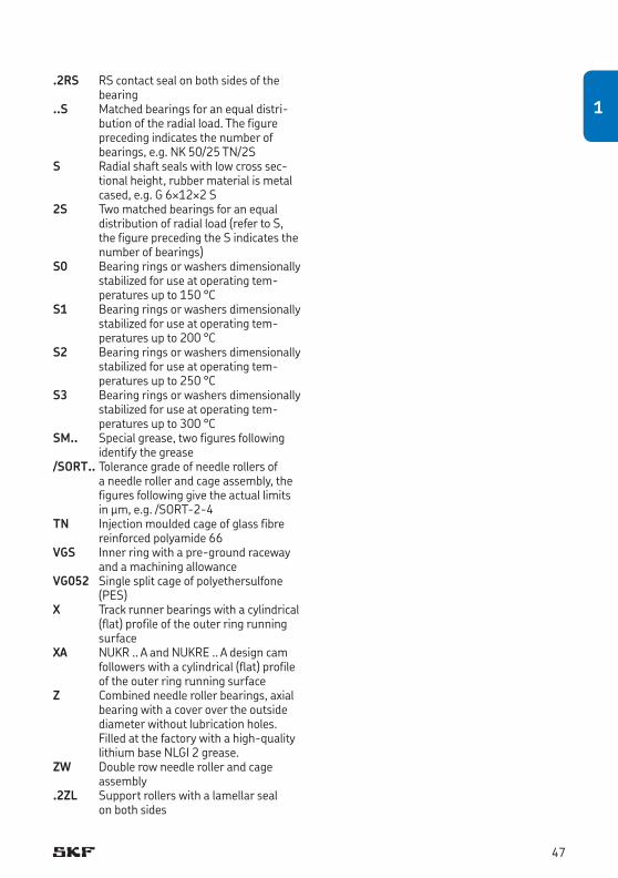
.2RS RS contact seal on both sides of the bearing
..S Matched bearings for an equal distri-bution of the radial load. The figure preceding indicates the number of bearings, e.g. NK 50/25 TN/2S
S Radial shaft seals with low cross sec-tional height, rubber material is metal cased, e.g. G 6¥12¥2 S
2S Two matched bearings for an equal distribution of radial load (refer to S, the figure preceding the S indicates the number of bearings)
S0 Bearing rings or washers dimensionally stabilized for use at operating tem-pera tures up to 150 °C
S1 Bearing rings or washers dimensionally stabilized for use at operating tem-pera tures up to 200 °C
S2 Bearing rings or washers dimensionally stabilized for use at operating tem-pera tures up to 250 °C
S3 Bearing rings or washers dimensionally stabilized for use at operating tem-pera tures up to 300 °C
SM.. Special grease, two figures following identify the grease
/SORT.. Tolerance grade of needle rollers of a needle roller and cage assembly, the figures following give the actual limits in μm, e.g. /SORT-2-4
TN Injectionmouldedcageofglassfibrereinforced polyamide 66
VGS Inner ring with a pre-ground raceway and a machining allowance
VG052 Single split cage of polyethersulfone (PES)
X Track runner bearings with a cylindrical (flat) profile of the outer ring running surface
XA NUKR .. A and NUKRE .. A design cam followers with a cylindrical (flat) profile of the outer ring running surface
Z Combined needle roller bearings, axial bearing with a cover over the outside diameter without lubrication holes. Filled at the factory with a high-quality lithium base NLGI 2 grease.
ZW Double row needle roller and cage assembly
.2ZL Support rollers with a lamellar seal on both sides
47
1
Application of bearings
Application of bearings
The bearing arrangement of a rotating machine component such as a shaft generally requires locating and a non-locating bearing arrange-ment to support and locate the component radially and axially relative to the housing. As radial needle roller bearings can accommodate axial displacement within the bearing, they generally are used as non-locating bearings.
Needle roller thrust bearings can only accom-modate axial loads acting in one direction. A double direction needle roller thrust bearing can be created by combining two needle roller and cage thrust assemblies and bearing washers with an intermediate washer. Radial loads must be accommodated by a combined needle roller bearing or a separate radial bearing.
Combined needle roller bearings can accom-modate radial loads and axial loads in one direc-tion only. Therefore, a second combined needle roller bearing is required to be able to take axial loads in the opposite direction (except NKIB series needle roller bearings that can accom-modate axial loads in both directions).
For additional information about bearing arrangements, refer to the SKF General Catalogue. The application information for bearings provided in the SKF General Catalogue is also valid for needle roller bearings.
If necessary, the introductory text of each product chapter provides information about
• axialguidance• axialandradiallocation• recommendedfitsforshaftsandhousings
Design of associated components
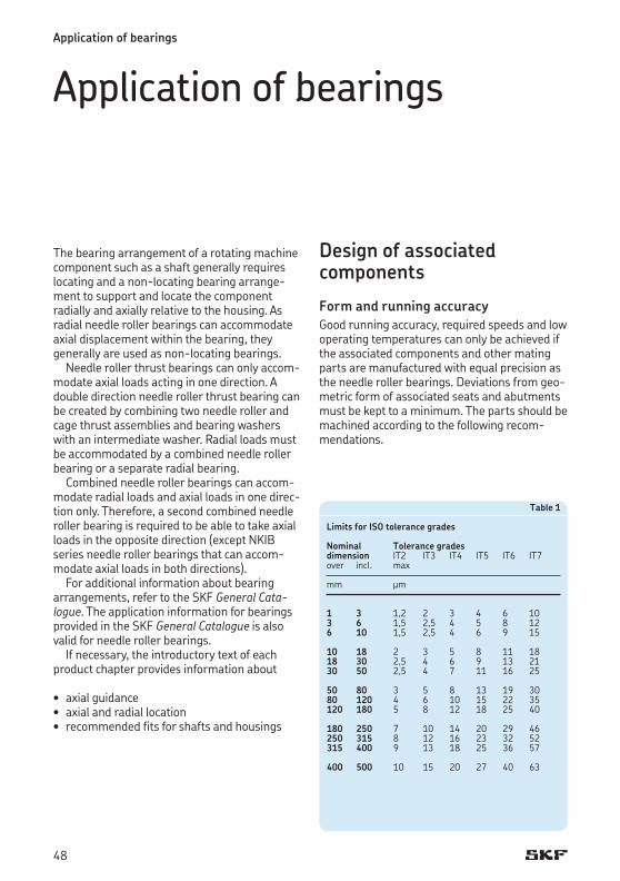
Form and running accuracyGood running accuracy, required speeds and low operating temperatures can only be achieved if the associated components and other mating parts are manufactured with equal precision as the needle roller bearings. Deviations from geo-metric form of associated seats and abutments must be kept to a minimum. The parts should be machined according to the following recom-mendations.
Table 1
Limits for ISO tolerance grades
Nominal Tolerance grades dimension IT2 IT3 IT4 IT5 IT6 IT7over incl. max
mm μm
1 3 1,2 2 3 4 6 103 6 1,5 2,5 4 5 8 126 10 1,5 2,5 4 6 9 15
10 18 2 3 5 8 11 1818 30 2,5 4 6 9 13 2130 50 2,5 4 7 11 16 25
50 80 3 5 8 13 19 3080 120 4 6 10 15 22 35120 180 5 8 12 18 25 40
180 250 7 10 14 20 29 46250 315 8 12 16 23 32 52315 400 9 13 18 25 36 57
400 500 10 15 20 27 40 63
48
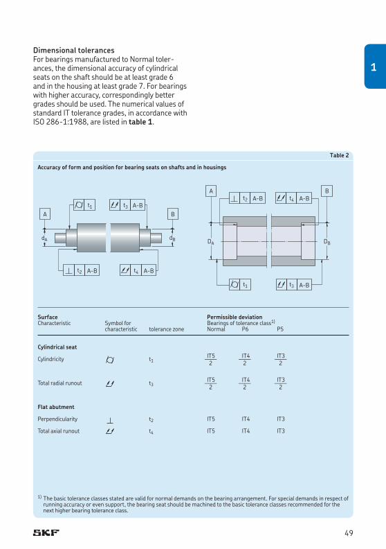
Table 2
Accuracy of form and position for bearing seats on shafts and in housings
Surface Permissible deviation Characteristic Symbol for Bearings of tolerance class1) characteristic tolerance zone Normal P6 P5
Cylindrical seat IT5 IT4 IT3Cylindricity t1 —— —— —— 2 2 2
IT5 IT4 IT3Total radial runout t3 —— —— —— 2 2 2
Flat abutment
Perpendicularity t2 IT5 IT4 IT3
Total axial runout t4 IT5 IT4 IT3
t1 t3 A-B
A-B A-Bt2 t4
A B
dA dB
t1
A-Bt4
t3 A-B
A BA-Bt2
DA DB
1) The basic tolerance classes stated are valid for normal demands on the bearing arrangement. For special demands in respect of running accuracy or even support, the bearing seat should be machined to the basic tolerance classes recommended for the next higher bearing tolerance class.
Dimensional tolerancesFor bearings manufactured to Normal toler-ances, the dimensional accuracy of cylindrical seats on the shaft should be at least grade 6 and in the housing at least grade 7. For bearings with higher accuracy, correspondingly better grades should be used. The numerical values of standard IT tolerance grades, in accordance with ISO 286-1:1988, are listed in table 1.
49
1
Application of bearings
Tolerances for cylindrical formThe cylindricity tolerances as defined in ISO 1101-2004 should be one to two IT grades better than the prescribed dimensional toler-ance, depending on requirements. For example, if a bearing shaft seat has been manufactured to m6 tolerance class, then the accuracy of form should be to IT5 or IT4 tolerance grade. The tolerance value for cylindricity, t1, is obtained for an assumed shaft diam eter of 150 mm from t1 = IT5/2 = 18/2 = 9 μm.However,thetolerancet1 is for a radius, hence 2 t1 applies for the shaft diameter. Guideline values for the cylindrical form tolerance and the total runout tolerance for the different bearing tolerance classes are listed in table 2 on page 49.
Tolerances for perpendicularityAbutments for bearing rings should have a rectangularity tolerance as defined in ISO 1101-2004, which is better by at least one IT grade than the diameter tolerance of the associated cylindrical seat. For thrust bearing washer seats, the tolerance for perpendicularity should not exceed IT5 tolerance grade. Guide-line values for the tolerance for rectangularity and for the total axial runout are listed in table 2 on page 49.
Surface roughness of bearing seatsThe surface roughness of a bearing seat does not have the same degree of influence on bear-ing performance as the dimensional, form and runningaccuracies.However,theaccuracyofaninterference fit is directly proportional to the smoothness of the mating surface.
For bearing arrangements where accuracy is a key operational parameter, guideline values for the mean surface roughness Ra are listed in table 3. These recommendations apply to ground seats, which are normally assumed for shaft seats.
Table 3
Guideline values for surface roughness of bearing seats
Diameter Recommended Ra valueof seat for ground seats d (D) Diameter tolerance toover incl. IT7 IT6 IT5
mm μm
– 80 1,6 (N7) 0,8 (N6) 0,4 (N5) 80 500 1,6 (N7) 1,6 (N7) 0,8 (N6)
Raceways on shafts and in housings
Raceway hardness and its influenceIf the load carrying capacity of the bearing or assembly is to be fully exploited, the raceways machined in associated components must be hardenedtobetween58and64HRC.
Raceway surface finish and accuracyThe surface roughness should be Ra ≤ 0,2 μm or Rz ≤ 1 μm. For less demanding applications, rougher surfaces may be used.
The out-of-round and deviation from cylin-drical form must not exceed 25 and 50%, respectively, of the actual diameter tolerance of the raceway.
The permissible axial runouts of raceways for thrust assemblies are the same as for the shaft and housing washers of thrust bearings, listed in table 5 on page 41.
Raceway materialsSuitable materials for the raceways include steel for through-hardening, e.g. 100Cr6 in accord-ance with ISO 683-17:1999, steels for case-hardening, e.g. 20Cr3 or 17MnCr5 in accord-ance with ISO 683-17:1999) as well as steels for induction-hardening that can be surface hardened.
50
The recommended hardening depth for raceways machined in associated components depends on various factors including the dynamic and static load ratios (P/C and P0/C0 respectively) as well as the core hardness of the component. Therefore, it is difficult to make generalizations regarding hardening depth. For example, under conditions of purely static load up to the magnitude of the basic static load rat-ing and with a core hardness of 350HV, the rec-ommended hardening depth is in the order of 0,1 times the rolling element diameter. For dynamic loads, however, smaller hardening depths are permitted. For additional informa-tion, contact the SKF application engineering service.
51
1
Lubrication
If rolling bearings are to operate reliably they must be adequately lubricated to prevent direct metal-to-metal contact between the rolling elem ents, raceways and cages. The lubricant also inhibits wear and protects the bearing sur-faces against corrosion. The choice of a suitable lubricant and method of lubrication for each individual bearing application is therefore important, as is adequate maintenance.
Differences in the lubricating properties of seemingly identical lubricants – particularly grease – produced at different locations can exist. As a result, SKF will not accept responsi-bility for the performance of any of its lubri-cants. The user is therefore advised to specify lubricant properties in detail so as to obtain the most suitable lubricant for the application.
The SKF traffic light conceptMost grease suppliers indicate the specific values for the low and high temperature limits in their product information. The SKF traffic light con-cept is distinctly different from that. SKF recog-nizes that the really important temperatures for reliable operation lie within a smaller range. This range depends largely on the type of base oil and thickener used, as well as the additives. The relevant temperatures are given by the SKF traffic light concept. They are schematically illustrated in diagram 1 in the form of a double traffic light.
It is clear that grease in the red zones should not be applied at all, as damage may occur. Within the green zone, the grease will function reliably and the grease life can be determined accurately.
At temperatures in the amber zone above the high temperature performance limit (HTPL), grease will age and oxidize with increasing rapidity and the by-products of the oxidation will have a detrimental effect on lubrication. An amber zone also exists for low temperatures. Short periods in this zone such as during a cold start are not harmful since the heat caused by friction will bring the bearing temperature into the green zone.
For additional information about the SKF traffic light concept, refer to the SKF General Catalogue (section Lubrication).
52
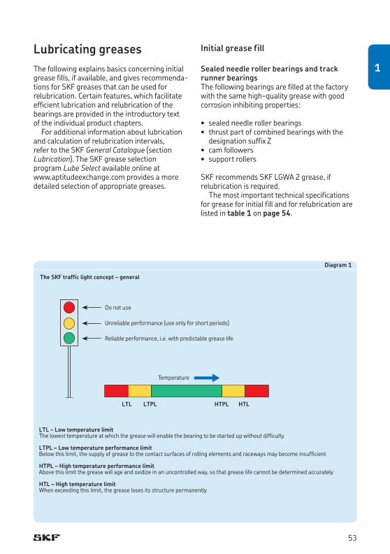
Diagram 1
The SKF traffic light concept – general
LTL – Low temperature limitThe lowest temperature at which the grease will enable the bearing to be started up without difficulty
LTPL – Low temperature performance limitBelow this limit, the supply of grease to the contact surfaces of rolling elements and raceways may become insufficient
HTPL – High temperature performance limitAbove this limit the grease will age and oxidize in an uncontrolled way, so that grease life cannot be determined accurately
HTL – High temperature limitWhen exceeding this limit, the grease loses its structure permanently
Lubricating greasesThe following explains basics concerning initial grease fills, if available, and gives recommenda-tions for SKF greases that can be used for relubri cation. Certain features, which facilitate efficient lubrication and relubrication of the bearings are provided in the introductory text of the individual product chapters.
For additional information about lubrication and calculation of relubrication intervals, refer to the SKF General Catalogue (section Lubrication). The SKF grease selection program Lube Select available online at www.aptitudeexchange.com provides a more detailed selection of appropriate greases.
Initial grease fill
Sealed needle roller bearings and track runner bearingsThe following bearings are filled at the factory with the same high-quality grease with good cor rosion inhibiting properties:
• sealedneedlerollerbearings• thrustpartofcombinedbearingswiththe
designation suffix Z• camfollowers• supportrollers
SKF recommends SKF LGWA 2 grease, if relubrication is required.
The most important technical specifications for grease for initial fill and for relubrication are listed in table 1 on page 54.
Temperature
LTL LTPL HTPL HTL
Do not use
Unreliable performance (use only for short periods)
Reliable performance, i.e. with predictable grease life
53
1
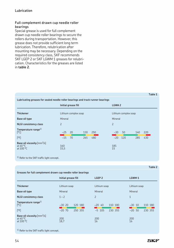
Lubrication
Table 1
Lubricating greases for sealed needle roller bearings and track runner bearings
Initial grease fill LGWA 2
Thickener Lithium complex soap Lithium complex soap
Base oil type Mineral Mineral
NLGI consistency class 2 2
Temperature range1)
[°C] –25 20 130 250 –30 50 140 220
[°F] –15 70 265 480 –20 120 285 430
Base oil viscosity [mm2/s]at 40 °C 160 185at 100 °C 15,5 15
Table 2
Greases for full complement drawn cup needle roller bearings
Initial grease fill LGEP 2 LGWM 1
Thickener Lithium soap Lithium soap Lithium soap
Base oil type Mineral Mineral Mineral
NLGI consistency class 1 – 2 2 1
Temperature range1)
[°C] –30 20 120 180 –20 40 110 180 –30 10 110 180
[°F] –20 70 250 355 –5 105 230 355 –20 50 230 355
Base oil viscosity [mm2/s]at 40 °C 200 200 200at 100 °C 18,7 16 16
1) Refer to the SKF traffic light concept.
1) Refer to the SKF traffic light concept.
Full complement drawn cup needle roller bearingsSpecial grease is used for full complement drawn cup needle roller bearings to secure the rollersduringtransportation.However,thisgrease does not provide sufficient long term lubrication. Therefore, relubrication after mounting may be necessary. Depending on the required consistency class, SKF recommends SKF LGEP 2 or SKF LGWM 1 greases for relubri-cation. Characteristics for the greases are listed in table 2.
54

55
1
Dimensions............................................................................................................ 58
Tolerances ............................................................................................................ 60
Operational clearance ............................................................................................ 60
Misalignment ......................................................................................................... 61
Cages .................................................................................................................... 62
Abutment dimensions ............................................................................................. 63
Supplementary designations ................................................................................... 63
Product tables ....................................................................................................... 642.1 Needle roller and cage assemblies ....................................................................................... 64
Needle roller and cage assemblies
2
57
2
57
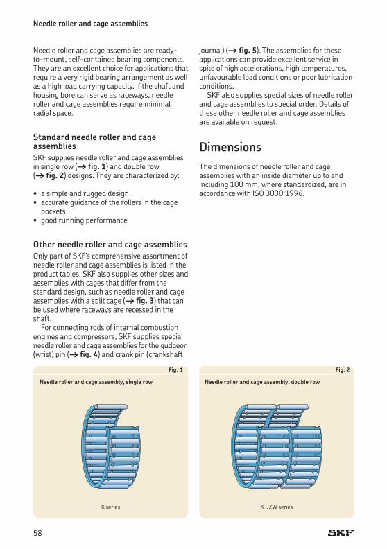
Needle roller and cage assemblies are ready- to-mount, self-contained bearing components. They are an excellent choice for applications that require a very rigid bearing arrangement as well as a high load carrying capacity. If the shaft and housing bore can serve as raceways, needle roller and cage assemblies require minimal radial space.
Standard needle roller and cage assembliesSKF supplies needle roller and cage assemblies in single row († fig. 1) and double row († fig. 2) designs. They are characterized by:
• asimpleandruggeddesign• accurateguidanceoftherollersinthecage
pockets• goodrunningperformance
Other needle roller and cage assembliesOnly part of SKF’s comprehensive assortment of needle roller and cage assemblies is listed in the product tables. SKF also supplies other sizes and assemblies with cages that differ from the standard design, such as needle roller and cage assemblies with a split cage († fig. 3) that can be used where raceways are recessed in the shaft.
For connecting rods of internal combustion engines and compressors, SKF supplies special needle roller and cage assemblies for the gudgeon (wrist) pin († fig. 4) and crank pin (crankshaft
Fig. 1
Needle roller and cage assembly, single row
Fig. 2
Needle roller and cage assembly, double row
Needle roller and cage assemblies
journal)(† fig. 5). The assemblies for these applications can provide excellent service in spite of high accelerations, high temperatures, unfavourable load conditions or poor lubrication conditions.
SKF also supplies special sizes of needle roller and cage assemblies to special order. Details of these other needle roller and cage assemblies are available on request.
DimensionsThe dimensions of needle roller and cage assemblies with an inside diameter up to and including 100 mm, where standardized, are in accordance with ISO 3030:1996.
K series K .. ZW series
58
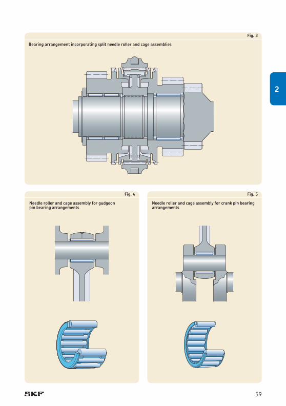
Fig. 3
Bearing arrangement incorporating split needle roller and cage assemblies
Fig. 4
Needle roller and cage assembly for gudgeon pin bearing arrangements
Fig. 5
Needle roller and cage assembly for crank pin bearing arrangements
59
2
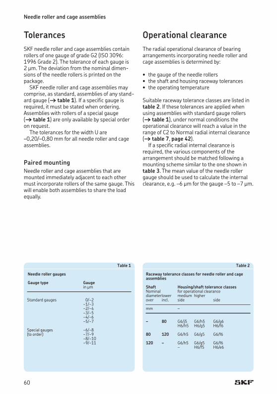
Needle roller and cage assemblies
TolerancesSKF needle roller and cage assemblies contain rollers of one gauge of grade G2 (ISO 3096: 1996 Grade 2). The tolerance of each gauge is 2 μm. The deviation from the nominal dimen-sions of the needle rollers is printed on the package.
SKF needle roller and cage assemblies may comprise, as standard, assemblies of any stand-ard gauge († table 1). If a specific gauge is required, it must be stated when ordering. Assemblies with rollers of a special gauge († table 1) are only available by special order on request.
The tolerances for the width U are –0,20/–0,80 mm for all needle roller and cage assemblies.
Paired mountingNeedle roller and cage assemblies that are mountedimmediatelyadjacenttoeachothermust incorporate rollers of the same gauge. This will enable both assemblies to share the load equally.
Table 1
Needle roller gauges
Gauge type Gauge in μm
Standard gauges 0/−2 −1/−3 −2/−4 −3/−5 −4/−6 −5/−7
Special gauges −6/−8(to order) −7/−9 −8/−10 −9/−11
Operational clearanceThe radial operational clearance of bearing arrangements incorporating needle roller and cage assemblies is determined by:
• thegaugeoftheneedlerollers• theshaftandhousingracewaytolerances• theoperatingtemperature
Suitable raceway tolerance classes are listed in table 2. If these tolerances are applied when using assemblies with standard gauge rollers († table 1), under normal conditions the operational clearance will reach a value in the range of C2 to Normal radial internal clearance († table 7, page 42).
If a specific radial internal clearance is required, the various components of the arrangement should be matched following a mounting scheme similar to the one shown in table 3. The mean value of the needle roller gauge should be used to calculate the internal clearance, e.g. –6 μm for the gauge –5 to –7 μm.
Table 2
Raceway tolerance classes for needle roller and cage assemblies
Shaft Housing/shaft tolerance classes Nominal for operational clearancediameter lower medium higherover incl. side side
mm –
– 80 G6/j5 G6/h5 G6/g6 H6/h5 H6/g5 H6/f6
80 120 G6/h5 G6/g5 G6/f6
120 – G6/h5 G6/g5 G6/f6 – H6/f5 H6/e6
60
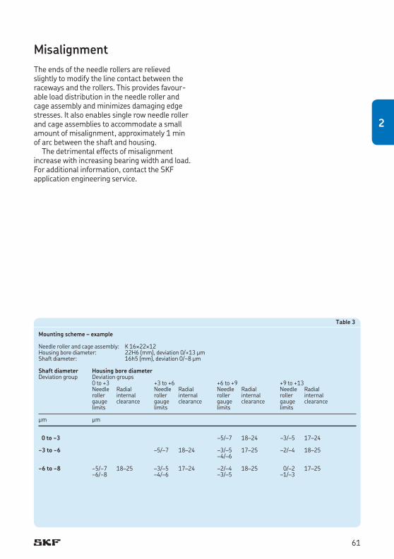
MisalignmentThe ends of the needle rollers are relieved slightly to modify the line contact between the raceways and the rollers. This provides favour-able load distribution in the needle roller and cage assembly and minimizes damaging edge stresses. It also enables single row needle roller and cage assemblies to accommodate a small amount of misalignment, approximately 1 min of arc between the shaft and housing.
The detrimental effects of misalignment increase with increasing bearing width and load. For additional information, contact the SKF application engineering service.
Table 3
Mounting scheme – example
Needle roller and cage assembly: K 16¥22¥12 Housingborediameter: 22H6(mm),deviation0/+13μmShaft diameter: 16h5 (mm), deviation 0/−8 μm
Shaft diameter Housing bore diameter Deviation group Deviation groups 0 to +3 +3 to +6 +6 to +9 +9 to +13 Needle Radial Needle Radial Needle Radial Needle Radial roller internal roller internal roller internal roller internal gauge clearance gauge clearance gauge clearance gauge clearance limits limits limits limits
μm μm
0 to −3 –5/–7 18–24 –3/–5 17–24
−3 to −6 –5/–7 18–24 –3/–5 17–25 –2/–4 18–25 –4/–6
−6 to −8 −5/−7 18–25 –3/–5 17–24 –2/–4 18–25 0/–2 17–25 −6/−8 –4/–6 –3/–5 –1/–3
61
2
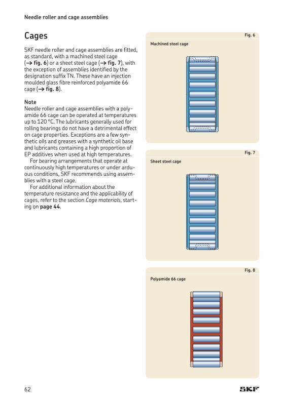
Needle roller and cage assemblies
Fig. 6
Machined steel cage
Fig. 7
Sheet steel cage
Fig. 8
Polyamide 66 cage
CagesSKF needle roller and cage assemblies are fitted, as standard, with a machined steel cage († fig. 6) or a sheet steel cage († fig. 7), with the exception of assemblies identified by the designation suffix TN.Thesehaveaninjectionmoulded glass fibre reinforced polyamide 66 cage († fig. 8).
Note Needle roller and cage assemblies with a poly-amide 66 cage can be operated at temperatures up to 120 °C. The lubricants generally used for rolling bearings do not have a detrimental effect on cage properties. Exceptions are a few syn-thetic oils and greases with a synthetic oil base and lubricants containing a high proportion of EP additives when used at high temperatures.
For bearing arrangements that operate at continuously high temperatures or under ardu-ous conditions, SKF recommends using assem-blies with a steel cage.
For additional information about the tempera ture resistance and the applicability of cages, refer to the section Cage materials, start-ing on page 44.
62
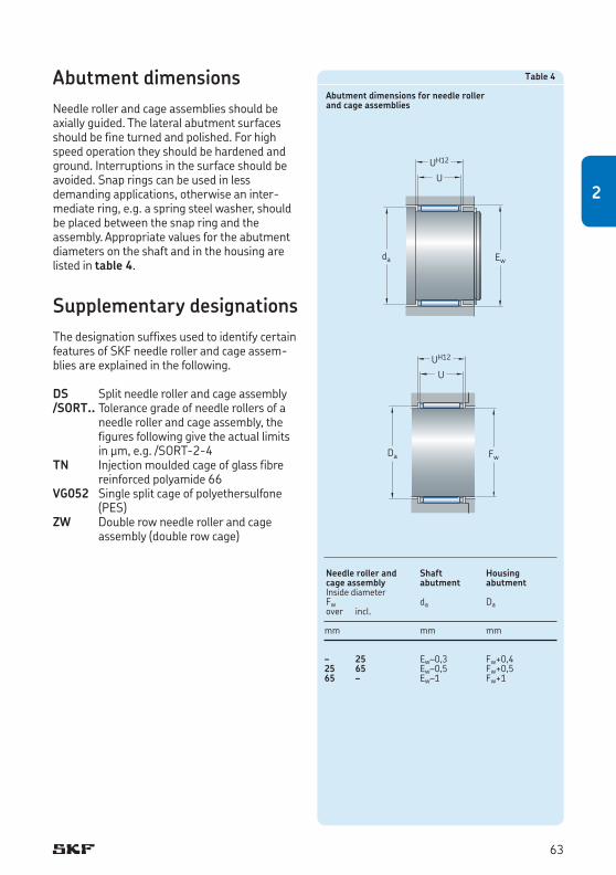
Abutment dimensionsNeedle roller and cage assemblies should be axially guided. The lateral abutment surfaces should be fine turned and polished. For high speed operation they should be hardened and ground. Interruptions in the surface should be avoided. Snap rings can be used in less demanding applications, otherwise an inter-medi ate ring, e.g. a spring steel washer, should be placed between the snap ring and the assembly. Appropriate values for the abutment diameters on the shaft and in the housing are listed in table 4.
Supplementary designationsThe designation suffixes used to identify certain features of SKF needle roller and cage assem-blies are explained in the following.
DS Split needle roller and cage assembly/SORT.. Tolerance grade of needle rollers of a
needle roller and cage assembly, the figures following give the actual limits in μm, e.g. /SORT-2-4
TN Injectionmouldedcageofglassfibrereinforced polyamide 66
VG052 Single split cage of polyethersulfone (PES)
ZW Double row needle roller and cage assembly (double row cage)
Table 4
Abutment dimensions for needle roller and cage assemblies
Needle roller and Shaft Housing cage assembly abutment abutmentInside diameterFw da Daover incl.
mm mm mm
– 25 Ew–0,3 Fw+0,425 65 Ew–0,5 Fw+0,565 – Ew–1 Fw+1
U
da Ew
UH12
U
Da Fw
UH12
63
2
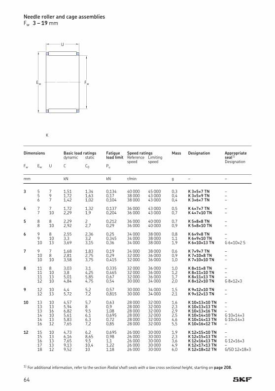
Dimensions Basic load ratings Fatigue Speed ratings Mass Designation Appropriate dynamic static load limit Reference Limiting seal1)
speed speed DesignationFw Ew U C C0 Pu
mm kN kN r/min g – –
3 5 7 1,51 1,34 0,134 40 000 45 000 0,3 K 3¥5¥7 TN – 5 9 1,72 1,63 0,17 38 000 43 000 0,4 K 3¥5¥9 TN – 6 7 1,42 1,02 0,104 38 000 43 000 0,4 K 3¥6¥7 TN – 4 7 7 1,72 1,32 0,137 36 000 43 000 0,5 K 4¥7¥7 TN – 7 10 2,29 1,9 0,204 36 000 43 000 0,7 K 4¥7¥10 TN – 5 8 8 2,29 2 0,212 36 000 40 000 0,7 K 5¥8¥8 TN – 8 10 2,92 2,7 0,29 36 000 40 000 0,9 K 5¥8¥10 TN – 6 9 8 2,55 2,36 0,25 34 000 38 000 0,8 K 6¥9¥8 TN – 9 10 3,3 3,2 0,345 34 000 38 000 1,1 K 6¥9¥10 TN – 10 13 3,69 3,15 0,36 34 000 38 000 1,9 K 6¥10¥13 TN G 6¥10¥2 S 7 9 7 1,68 1,83 0,19 34 000 38 000 0,6 K 7¥9¥7 TN – 10 8 2,81 2,75 0,29 32 000 36 000 0,9 K 7¥10¥8 TN – 10 10 3,58 3,75 0,415 32 000 36 000 1,0 K 7¥10¥10 TN – 8 11 8 3,03 3,1 0,335 32 000 36 000 1,0 K 8¥11¥8 TN – 11 10 3,8 4,25 0,465 32 000 36 000 1,2 K 8¥11¥10 TN – 11 13 5,01 5,85 0,67 32 000 36 000 1,7 K 8¥11¥13 TN – 12 10 4,84 4,75 0,54 30 000 34 000 2,0 K 8¥12¥10 TN G 8¥12¥3 9 12 10 4,4 5,2 0,57 30 000 34 000 1,5 K 9¥12¥10 TN – 12 13 5,72 7,2 0,815 30 000 34 000 2,1 K 9¥12¥13 TN – 10 13 10 4,57 5,7 0,63 28 000 32 000 1,6 K 10¥13¥10 TN – 13 13 5,94 8 0,9 28 000 32 000 2,3 K 10¥13¥13 TN – 13 16 6,82 9,5 1,08 28 000 32 000 2,9 K 10¥13¥16 TN – 14 10 5,61 6,1 0,695 28 000 32 000 2,5 K 10¥14¥10 TN G 10¥14¥3 14 13 5,83 6,3 0,72 28 000 32 000 4,6 K 10¥14¥13 TN G 10¥14¥3 16 12 7,65 7,2 0,85 28 000 32 000 5,5 K 10¥16¥12 TN – 12 15 10 4,73 6,2 0,695 26 000 30 000 1,9 K 12¥15¥10 TN – 15 13 6,16 8,65 0,98 26 000 30 000 2,3 K 12¥15¥13 TN – 16 13 7,65 9,5 1,1 26 000 30 000 3,6 K 12¥16¥13 TN G 12¥16¥3 17 13 9,13 10,4 1,22 26 000 30 000 4,9 K 12¥17¥13 TN – 18 12 9,52 10 1,18 26 000 30 000 6,0 K 12¥18¥12 TN G/SD 12¥18¥3
Needle roller and cage assembliesFw 3 – 19 mm
1) For additional information, refer to the section Radial shaft seals with a low cross sectional height, starting on page 208.
FwEw
U
K
64
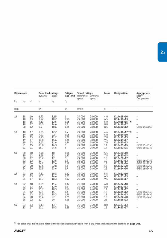
14 18 10 6,93 8,65 1 24 000 28 000 4,0 K 14¥18¥10 – 18 13 7,92 10,2 1,18 24 000 28 000 6,5 K 14¥18¥13 – 18 15 9,13 12,5 1,46 24 000 28 000 5,0 K 14¥18¥15 TN – 18 17 10,5 14,6 1,7 24 000 28 000 8,0 K 14¥18¥17 – 20 12 9,9 10,6 1,25 24 000 28 000 8,5 K 14¥20¥12 G/SD 14¥20¥3 15 18 17 7,65 12,2 1,4 24 000 28 000 4,6 K 15¥18¥17 TN – 19 10 7,21 9,3 1,06 24 000 28 000 5,0 K 15¥19¥10 – 19 13 8,25 11,2 1,29 24 000 28 000 7,0 K 15¥19¥13 – 19 17 10,8 15,6 1,86 24 000 28 000 9,5 K 15¥19¥17 – 20 13 9,52 11,6 1,34 24 000 26 000 7,0 K 15¥20¥13 – 21 15 13,8 16,3 2 24 000 26 000 11 K 15¥21¥15 G/SD 15¥21¥3 21 21 18,7 24,5 3 24 000 26 000 17 K 15¥21¥21 G/SD 15¥21¥3 16 20 10 7,48 10 1,16 24 000 26 000 5,5 K 16¥20¥10 – 20 13 8,58 12 1,37 24 000 26 000 7,5 K 16¥20¥13 – 20 17 11,2 17 2 24 000 26 000 10 K 16¥20¥17 – 22 12 11 12,5 1,5 22 000 26 000 10 K 16¥22¥12 G/SD 16¥22¥3 22 16 14,2 17,6 2,12 22 000 26 000 12 K 16¥22¥16 G/SD 16¥22¥3 22 20 17,6 22,8 2,8 22 000 26 000 17 K 16¥22¥20 G/SD 16¥22¥3 24 20 20,5 23,6 2,9 22 000 24 000 22 K 16¥24¥20 G/SD 16¥24¥3 17 21 10 7,81 10,8 1,22 22 000 26 000 5,5 K 17¥21¥10 – 21 13 10,1 14,6 1,73 22 000 26 000 6,5 K 17¥21¥13 – 21 17 11,7 18,3 2,12 22 000 26 000 9,5 K 17¥21¥17 – 18 22 10 8,09 11,4 1,32 22 000 24 000 6,0 K 18¥22¥10 – 22 13 8,8 12,9 1,5 22 000 24 000 8,0 K 18¥22¥13 – 22 17 11,7 18,3 2,16 22 000 24 000 11 K 18¥22¥17 – 24 12 12,1 15 1,8 20 000 24 000 12 K 18¥24¥12 G/SD 18¥24¥3 24 13 12,5 15,3 1,86 20 000 24 000 13 K 18¥24¥13 G/SD 18¥24¥3 24 20 19,4 27 3,25 20 000 24 000 18 K 18¥24¥20 G/SD 18¥24¥3 25 22 22 29 3,55 20 000 24 000 23 K 18¥25¥22 – 19 23 13 9,13 13,7 1,6 20 000 24 000 8,0 K 19¥23¥13 – 23 17 12,1 19,3 2,28 20 000 24 000 11 K 19¥23¥17 –
Dimensions Basic load ratings Fatigue Speed ratings Mass Designation Appropriate dynamic static load limit Reference Limiting seal1)
speed speed DesignationFw Ew U C C0 Pu
mm kN kN r/min g – –
1) For additional information, refer to the section Radial shaft seals with a low cross sectional height, starting on page 208.
65
2.1
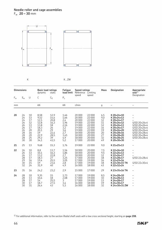
20 24 10 8,58 12,9 1,46 20 000 22 000 6,5 K 20¥24¥10 – 24 13 9,52 14,6 1,66 20 000 22 000 9,0 K 20¥24¥13 – 24 17 12,5 20,8 2,4 20 000 22 000 12 K 20¥24¥17 – 26 12 12,8 16,3 1,96 19 000 22 000 11 K 20¥26¥12 G/SD 20¥26¥4 26 13 13,8 18 2,16 19 000 22 000 12 K 20¥26¥13 G/SD 20¥26¥4 26 17 18,3 26 3,2 19 000 22 000 16 K 20¥26¥17 G/SD 20¥26¥4 26 20 20,1 29 3,6 19 000 22 000 19 K 20¥26¥20 G/SD 20¥26¥4 28 16 19 22,4 2,7 18 000 20 000 20 K 20¥28¥16 G/SD 20¥28¥4 28 20 22,9 28,5 3,45 18 000 20 000 27 K 20¥28¥20 G/SD 20¥28¥4 28 25 29,2 39 4,9 18 000 20 000 32 K 20¥28¥25 G/SD 20¥28¥4 30 30 34,1 41,5 5,2 17 000 20 000 49 K 20¥30¥30 – 21 25 13 9,68 15,3 1,76 19 000 22 000 9,0 K 21¥25¥13 – 22 26 10 8,8 13,7 1,56 18 000 20 000 7,5 K 22¥26¥10 – 26 13 10,1 16,3 1,86 18 000 20 000 9,5 K 22¥26¥13 – 26 17 13,2 22,8 2,7 18 000 20 000 12 K 22¥26¥17 – 28 17 18,3 27 3,25 17 000 20 000 18 K 22¥28¥17 G/SD 22¥28¥4 29 16 19,4 25,5 3,05 17 000 19 000 16 K 22¥29¥16 30 15 19 23,6 2,8 17 000 19 000 18 K 22¥30¥15 TN G/SD 22¥30¥4 32 24 31,9 40 4,9 16 000 18 000 43 K 22¥32¥24 – 23 35 16 24,2 23,2 2,9 15 000 17 000 29 K 23¥35¥16 TN – 24 28 10 9,35 15 1,73 17 000 19 000 8,5 K 24¥28¥10 – 28 13 10,6 18 2,08 17 000 19 000 10 K 24¥28¥13 – 28 17 14 25,5 3 17 000 19 000 13 K 24¥28¥17 – 30 17 18,7 27,5 3,4 16 000 18 000 19 K 24¥30¥17 – 30 31 26,4 43 5,3 16 000 18 000 32 K 24¥30¥31 ZW –
Dimensions Basic load ratings Fatigue Speed ratings Mass Designation Appropriate dynamic static load limit Reference Limiting seal1)
speed speed DesignationFw Ew U C C0 Pu
mm kN kN r/min g – –
Needle roller and cage assembliesFw 20 – 30 mm
1) For additional information, refer to the section Radial shaft seals with a low cross sectional height, starting on page 208.
FwEw
U
K K .. ZW
66
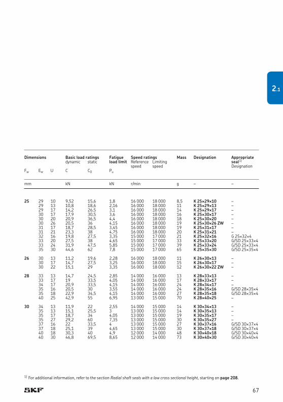
25 29 10 9,52 15,6 1,8 16 000 18 000 8,5 K 25¥29¥10 – 29 13 10,8 18,6 2,16 16 000 18 000 11 K 25¥29¥13 – 29 17 14,2 26,5 3,1 16 000 18 000 14 K 25¥29¥17 – 30 17 17,9 30,5 3,6 16 000 18 000 16 K 25¥30¥17 – 30 20 20,9 36,5 4,4 16 000 18 000 18 K 25¥30¥20 – 30 26 20,5 36 4,15 16 000 18 000 19 K 25¥30¥26 ZW – 31 17 18,7 28,5 3,45 16 000 18 000 19 K 25¥31¥17 – 31 21 23,3 38 4,75 16 000 18 000 20 K 25¥31¥21 – 32 16 19,8 27,5 3,35 15 000 17 000 21 K 25¥32¥16 G 25¥32¥4 33 20 27,5 38 4,65 15 000 17 000 33 K 25¥33¥20 G/SD 25¥33¥4 33 24 31,9 47,5 5,85 15 000 17 000 39 K 25¥33¥24 G/SD 25¥33¥4 35 30 44,6 62 7,8 15 000 17 000 65 K 25¥35¥30 G/SD 25¥35¥4 26 30 13 11,2 19,6 2,28 16 000 18 000 11 K 26¥30¥13 – 30 17 14,7 27,5 3,25 16 000 18 000 15 K 26¥30¥17 – 30 22 15,1 29 3,35 16 000 18 000 12 K 26¥30¥22 ZW – 28 33 13 14,7 24,5 2,85 14 000 16 000 13 K 28¥33¥13 – 33 17 19 33,5 4,05 14 000 16 000 17 K 28¥33¥17 – 34 17 20,9 33,5 4,15 14 000 16 000 24 K 28¥34¥17 – 35 16 20,5 30 3,55 14 000 16 000 24 K 28¥35¥16 G/SD 28¥35¥4 35 18 22,9 34,5 4,15 14 000 16 000 27 K 28¥35¥18 G/SD 28¥35¥4 40 25 42,9 55 6,95 13 000 15 000 70 K 28¥40¥25 – 30 34 13 11,9 22 2,55 14 000 15 000 14 K 30¥34¥13 – 35 13 15,1 25,5 3 13 000 15 000 14 K 30¥35¥13 – 35 17 18,7 34 4,05 13 000 15 000 19 K 30¥35¥17 – 35 27 29,2 60 7,35 13 000 15 000 30 K 30¥35¥27 – 37 16 22 33,5 4 13 000 15 000 27 K 30¥37¥16 G/SD 30¥37¥4 37 18 25,1 39 4,65 13 000 15 000 30 K 30¥37¥18 G/SD 30¥37¥4 40 18 30,3 40 4,9 12 000 14 000 48 K 30¥40¥18 G/SD 30¥40¥4 40 30 46,8 69,5 8,65 12 000 14 000 73 K 30¥40¥30 G/SD 30¥40¥4
Dimensions Basic load ratings Fatigue Speed ratings Mass Designation Appropriate dynamic static load limit Reference Limiting seal1)
speed speed DesignationFw Ew U C C0 Pu
mm kN kN r/min g – –
1) For additional information, refer to the section Radial shaft seals with a low cross sectional height, starting on page 208.
67
2.1
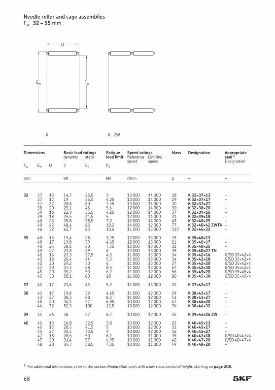
32 37 13 14,7 25,5 3 13 000 14 000 18 K 32¥37¥13 – 37 17 19 35,5 4,25 13 000 14 000 19 K 32¥37¥17 – 37 27 28,6 60 7,35 13 000 14 000 30 K 32¥37¥27 – 38 20 25,1 45 5,6 12 000 14 000 30 K 32¥38¥20 – 39 16 22,9 35,5 4,25 12 000 14 000 37 K 32¥39¥16 – 39 18 25,5 41,5 5 12 000 14 000 31 K 32¥39¥18 – 40 25 35,8 58,5 7,2 12 000 14 000 49 K 32¥40¥25 – 40 42 48,4 83 10,2 14 000 12 000 77 K 32¥40¥42 ZWTN – 46 32 62,7 83 10,4 11 000 13 000 119 K 32¥46¥32 – 35 40 13 15,4 28 3,25 12 000 13 000 19 K 35¥40¥13 – 40 17 19,8 39 4,65 12 000 13 000 21 K 35¥40¥17 – 40 25 28,1 60 7,35 12 000 13 000 31 K 35¥40¥25 – 40 27 23,8 49 6 12 000 13 000 39 K 35¥40¥27 TN – 42 16 23,3 37,5 4,5 11 000 13 000 34 K 35¥42¥16 G/SD 35¥42¥4 42 18 26,4 44 5,3 11 000 13 000 34 K 35¥42¥18 G/SD 35¥42¥4 42 20 29,2 50 6 11 000 13 000 37 K 35¥42¥20 G/SD 35¥42¥4 42 30 37,4 68 8,5 11 000 13 000 67 K 35¥42¥30 G/SD 35¥42¥4 45 20 35,2 50 6,2 11 000 12 000 56 K 35¥45¥20 G/SD 35¥45¥4 45 30 50,1 80 10 11 000 12 000 80 K 35¥45¥30 G/SD 35¥45¥4 37 42 17 21,6 43 5,2 11 000 13 000 22 K 37¥42¥17 – 38 43 17 19,8 39 4,65 11 000 12 000 29 K 38¥43¥17 – 43 27 30,3 68 8,3 11 000 12 000 43 K 38¥43¥27 – 46 20 34,1 57 6,95 10 000 12 000 47 K 38¥46¥20 – 46 32 52,3 100 12,5 10 000 12 000 76 K 38¥46¥32 – 39 44 26 26 57 6,7 10 000 12 000 45 K 39¥44¥26 ZW – 40 45 13 16,8 32,5 3,8 10 000 12 000 22 K 40¥45¥13 – 45 17 20,5 41,5 5 10 000 12 000 31 K 40¥45¥17 – 45 27 31,4 73,5 9 10 000 12 000 46 K 40¥45¥27 – 47 18 28,6 50 6,1 10 000 11 000 39 K 40¥47¥18 G/SD 40¥47¥4 47 20 31,4 57 6,95 10 000 11 000 42 K 40¥47¥20 G/SD 40¥47¥4 48 20 34,7 58,5 7,35 10 000 11 000 49 K 40¥48¥20 –
Dimensions Basic load ratings Fatigue Speed ratings Mass Designation Appropriate dynamic static load limit Reference Limiting seal1)
speed speed DesignationFw Ew U C C0 Pu
mm kN kN r/min g – –
Needle roller and cage assembliesFw 32 – 55 mm
1) For additional information, refer to the section Radial shaft seals with a low cross sectional height, starting on page 208.
FwEw
U
K K .. ZW
68
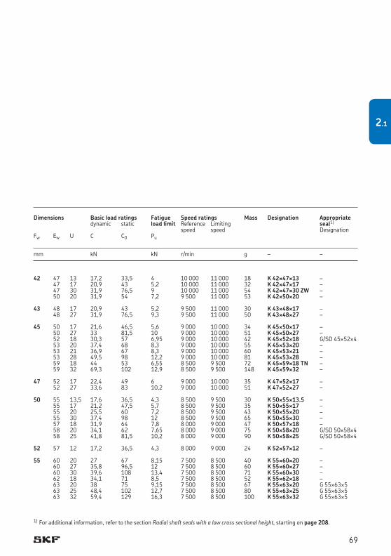
42 47 13 17,2 33,5 4 10 000 11 000 18 K 42¥47¥13 – 47 17 20,9 43 5,2 10 000 11 000 32 K 42¥47¥17 – 47 30 31,9 76,5 9 10 000 11 000 54 K 42¥47¥30 ZW – 50 20 31,9 54 7,2 9 500 11 000 53 K 42¥50¥20 – 43 48 17 20,9 43 5,2 9 500 11 000 30 K 43¥48¥17 – 48 27 31,9 76,5 9,3 9 500 11 000 50 K 43¥48¥27 – 45 50 17 21,6 46,5 5,6 9 000 10 000 34 K 45¥50¥17 – 50 27 33 81,5 10 9 000 10 000 51 K 45¥50¥27 – 52 18 30,3 57 6,95 9 000 10 000 42 K 45¥52¥18 G/SD 45¥52¥4 53 20 37,4 68 8,3 9 000 10 000 55 K 45¥53¥20 – 53 21 36,9 67 8,3 9 000 10 000 60 K 45¥53¥21 – 53 28 49,5 98 12,2 9 000 10 000 81 K 45¥53¥28 – 59 18 44 53 6,55 8 500 9 500 72 K 45¥59¥18 TN – 59 32 69,3 102 12,9 8 500 9 500 148 K 45¥59¥32 – 47 52 17 22,4 49 6 9 000 10 000 35 K 47¥52¥17 – 52 27 33,6 83 10,2 9 000 10 000 51 K 47¥52¥27 – 50 55 13,5 17,6 36,5 4,3 8 500 9 500 30 K 50¥55¥13.5 – 55 17 21,2 47,5 5,7 8 500 9 500 35 K 50¥55¥17 – 55 20 25,5 60 7,2 8 500 9 500 43 K 50¥55¥20 – 55 30 37,4 98 12 8 500 9 500 65 K 50¥55¥30 – 57 18 31,9 64 7,8 8 000 9 000 47 K 50¥57¥18 – 58 20 34,1 62 7,65 8 000 9 000 75 K 50¥58¥20 G/SD 50¥58¥4 58 25 41,8 81,5 10,2 8 000 9 000 90 K 50¥58¥25 G/SD 50¥58¥4 52 57 12 17,2 36,5 4,3 8 000 9 000 24 K 52¥57¥12 – 55 60 20 27 67 8,15 7 500 8 500 40 K 55¥60¥20 – 60 27 35,8 96,5 12 7 500 8 500 60 K 55¥60¥27 – 60 30 39,6 108 13,4 7 500 8 500 71 K 55¥60¥30 – 62 18 34,1 71 8,5 7 500 8 500 52 K 55¥62¥18 – 63 20 38 75 9,15 7 500 8 500 67 K 55¥63¥20 G 55¥63¥5 63 25 48,4 102 12,7 7 500 8 500 80 K 55¥63¥25 G 55¥63¥5 63 32 59,4 129 16,3 7 500 8 500 100 K 55¥63¥32 G 55¥63¥5
Dimensions Basic load ratings Fatigue Speed ratings Mass Designation Appropriate dynamic static load limit Reference Limiting seal1)
speed speed DesignationFw Ew U C C0 Pu
mm kN kN r/min g – –
1) For additional information, refer to the section Radial shaft seals with a low cross sectional height, starting on page 208.
69
2.1
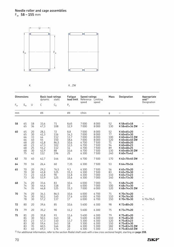
58 65 18 33,6 71 8,65 7 000 8 000 52 K 58¥65¥18 – 65 36 47,3 108 12,9 7 000 8 000 130 K 58¥65¥36 ZW – 60 65 20 28,1 72 8,8 7 000 8 000 52 K 60¥65¥20 – 65 30 41,3 116 14,3 7 000 8 000 77 K 60¥65¥30 – 66 33 44 112 13,7 7 000 8 000 100 K 60¥66¥33 ZW – 66 40 55 150 18,6 7 000 8 000 120 K 60¥66¥40 ZW – 68 20 41,8 86,5 10,6 6 700 7 500 71 K 60¥68¥20 – 68 23 47,3 102 12,5 6 700 7 500 94 K 60¥68¥23 – 68 25 51,2 112 14 6 700 7 500 89 K 60¥68¥25 – 68 30 42,9 88 10,6 6 700 7 500 130 K 60¥68¥30 ZW – 75 42 112 196 25 6 300 7 500 240 K 60¥75¥42 – 62 70 40 62,7 146 18,6 6 700 7 500 170 K 62¥70¥40 ZW – 64 70 16 26,4 60 7,35 6 300 7 500 53 K 64¥70¥16 – 65 70 20 29,2 76,5 9,3 6 300 7 500 56 K 65¥70¥20 – 70 30 41,8 125 15,3 6 300 7 500 83 K 65¥70¥30 – 73 23 41,8 90 11,8 6 300 7 000 110 K 65¥73¥23 – 73 30 53,9 125 15,6 6 300 7 000 140 K 65¥73¥30 – 68 74 20 33,6 83 10,4 6 000 7 000 71 K 68¥74¥20 – 74 30 44,6 118 15 6 000 7 000 100 K 68¥74¥30 – 74 35 46,8 125 15,3 7 000 6 000 120 K 68¥74¥35 ZW – 70 76 20 34,1 86,5 10,6 6 000 6 700 71 K 70¥76¥20 – 76 30 50,1 140 17,6 6 000 6 700 110 K 70¥76¥30 – 78 30 57,2 137 17 6 000 6 700 150 K 70¥78¥30 G 70¥78¥5 72 80 20 39,6 85 10,6 5 600 6 300 98 K 72¥80¥20 – 73 79 20 35,2 90 11,2 5 600 6 300 75 K 73¥79¥20 – 75 81 20 35,8 93 11,6 5 600 6 300 79 K 75¥81¥20 – 81 30 50,1 143 18 5 600 6 300 110 K 75¥81¥30 – 83 23 47,3 110 13,7 5 300 6 300 120 K 75¥83¥23 – 83 30 59,4 143 18 5 300 6 300 150 K 75¥83¥30 – 83 35 60,5 146 18 6 300 5 300 182 K 75¥83¥35 ZW – 83 40 69,3 176 22 6 300 5 300 211 K 75¥83¥40 ZW –1) For additional information, refer to the section Radial shaft seals with a low cross sectional height, starting on page 208.
Dimensions Basic load ratings Fatigue Speed ratings Mass Designation Appropriate dynamic static load limit Reference Limiting seal1)
speed speed DesignationFw Ew U C C0 Pu
mm kN kN r/min g – –
Needle roller and cage assembliesFw 58 – 155 mm
K .. ZW
FwEw
U
K
70
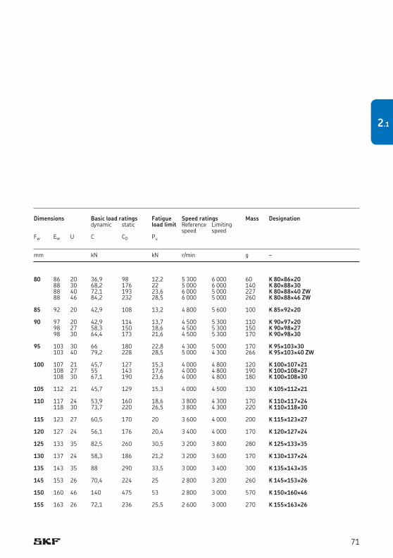
80 86 20 36,9 98 12,2 5 300 6 000 60 K 80¥86¥20 88 30 68,2 176 22 5 000 6 000 140 K 80¥88¥30 88 40 72,1 193 23,6 6 000 5 000 227 K 80¥88¥40 ZW 88 46 84,2 232 28,5 6 000 5 000 260 K 80¥88¥46 ZW 85 92 20 42,9 108 13,2 4 800 5 600 100 K 85¥92¥20 90 97 20 42,9 114 13,7 4 500 5 300 110 K 90¥97¥20 98 27 58,3 150 18,6 4 500 5 300 150 K 90¥98¥27 98 30 64,4 173 21,6 4 500 5 300 170 K 90¥98¥30 95 103 30 66 180 22,8 4 300 5 000 170 K 95¥103¥30 103 40 79,2 228 28,5 5 000 4 300 266 K 95¥103¥40 ZW 100 107 21 45,7 127 15,3 4 000 4 800 120 K 100¥107¥21 108 27 55 143 17,6 4 000 4 800 190 K 100¥108¥27 108 30 67,1 190 23,6 4 000 4 800 180 K 100¥108¥30 105 112 21 45,7 129 15,3 4 000 4 500 130 K 105¥112¥21 110 117 24 53,9 160 18,6 3 800 4 300 170 K 110¥117¥24 118 30 73,7 220 26,5 3 800 4 300 220 K 110¥118¥30 115 123 27 60,5 170 20 3 600 4 000 200 K 115¥123¥27 120 127 24 56,1 176 20,4 3 400 4 000 170 K 120¥127¥24 125 133 35 82,5 260 30,5 3 200 3 800 280 K 125¥133¥35 130 137 24 58,3 186 21,2 3 200 3 600 170 K 130¥137¥24 135 143 35 88 290 33,5 3 000 3 400 300 K 135¥143¥35 145 153 26 70,4 224 25 2 800 3 200 260 K 145¥153¥26 150 160 46 140 475 53 2 800 3 000 570 K 150¥160¥46 155 163 26 72,1 236 25,5 2 600 3 000 270 K 155¥163¥26
Dimensions Basic load ratings Fatigue Speed ratings Mass Designation dynamic static load limit Reference Limiting speed speed Fw Ew U C C0 Pu
mm kN kN r/min g –
71
2.1

160 170 46 145 510 56 2 600 2 800 550 K 160¥170¥46 165 173 26 76,5 265 28,5 2 400 2 800 320 K 165¥173¥26 175 183 32 95,2 355 37,5 2 400 2 600 400 K 175¥183¥32 185 195 37 123 425 45 2 200 2 400 610 K 185¥195¥37 195 205 37 125 450 46,5 2 000 2 400 620 K 195¥205¥37 210 220 42 147 560 57 1 900 2 200 740 K 210¥220¥42 220 230 42 151 585 58,5 1 800 2 000 790 K 220¥230¥42 240 250 42 157 630 62 1 700 1 900 850 K 240¥250¥42 265 280 50 242 850 83 1 500 1 700 1 800 K 265¥280¥50
Dimensions Basic load ratings Fatigue Speed ratings Mass Designation dynamic static load limit Reference Limiting speed speed Fw Ew U C C0 Pu
mm kN kN r/min g –
Needle roller and cage assembliesFw 160 – 265 mm
FwEw
U
K
72

73
2.1
Drawn cup needle roller bearings
Sealed drawn cup needle roller bearings .................................................................. 78
Full complement drawn cup needle roller bearings ................................................... 79
Dimensions............................................................................................................ 79
Tolerances ............................................................................................................ 79
Misalignment ......................................................................................................... 80
Cages .................................................................................................................... 80
Shaft and housing tolerances .................................................................................. 80
Operational clearance ............................................................................................ 80
Mounting instructions ............................................................................................ 81
Static safety factor ................................................................................................. 81
Supplementary designations ................................................................................... 81
Product tables ....................................................................................................... 823.1 Drawn cup needle roller bearings ........................................................................................ 82
3
75
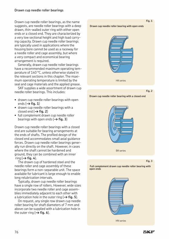
Drawn cup needle roller bearings
Drawn cup needle roller bearings, as the name suggests, are needle roller bearings with a deep drawn, thin-walled outer ring with either open ends or a closed end. They are characterized by a very low sectional height and high load carry-ing capacity. Drawn cup needle roller bearings are typically used in applications where the housing bore cannot be used as a raceway for a needle roller and cage assembly, but where a very compact and economical bearing arrangement is required.
Generally, drawn cup needle roller bearings have a recommended maximum operating tem-perature of 140 °C, unless otherwise stated in the relevant sections in this chapter. The maxi-mum operating temperature is limited by the seal and cage materials and the applied grease.
SKF supplies a wide assortment of drawn cup needle roller bearings. This includes:
• drawncupneedlerollerbearingswithopenends († fig. 1)• drawncupneedlerollerbearingswitha
closed end († fig. 2) • fullcomplementdrawncupneedleroller
bearings with open ends († fig. 3)
Drawn cup needle roller bearings with a closed end are suitable for bearing arrangements at the ends of shafts. The profiled design of the closed end accommodates small axial guidance forces. Drawn cup needle roller bearings gener-allyrundirectlyontheshaft.However,incaseswhere the shaft cannot be hardened and ground, they can be combined with an inner ring († fig. 4).
The drawn cup of hardened steel and the needle roller and cage assembly of these bearings form a non-separable unit. The space available for lubricant is large enough to enable long relubrication intervals.
Typically, drawn cup needle roller bearings haveasinglerowofrollers.However,widesizesincorporate two needle roller and cage assem-bliesimmediatelyadjacenttoeachotherwith a lubrication hole in the outer ring († fig. 5).
On request, any single row drawn cup needle roller bearing for shaft diameters of 7 mm and above can be supplied with a lubrication hole in the outer ring († fig. 6).
Fig. 2
Drawn cup needle roller bearing with a closed end
Fig. 1
Drawn cup needle roller bearing with open ends
Fig. 3
Full complement drawn cup needle roller bearing with open ends
HKseries
BK series
HNseries
76
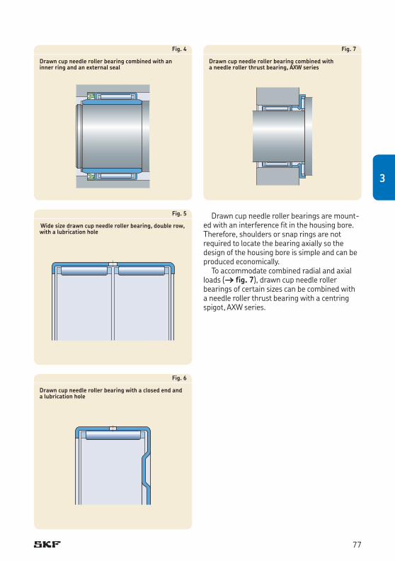
Fig. 5
Wide size drawn cup needle roller bearing, double row, with a lubrication hole
Fig. 4
Drawn cup needle roller bearing combined with an inner ring and an external seal
Fig. 6
Drawn cup needle roller bearing with a closed end and a lubrication hole
Fig. 7
Drawn cup needle roller bearing combined with a needle roller thrust bearing, AXW series
Drawn cup needle roller bearings are mount-ed with an interference fit in the housing bore. Therefore, shoulders or snap rings are not required to locate the bearing axially so the design of the housing bore is simple and can be produced economically.
To accommodate combined radial and axial loads († fig. 7), drawn cup needle roller bearings of certain sizes can be combined with a needle roller thrust bearing with a centring spigot, AXW series.
77
3
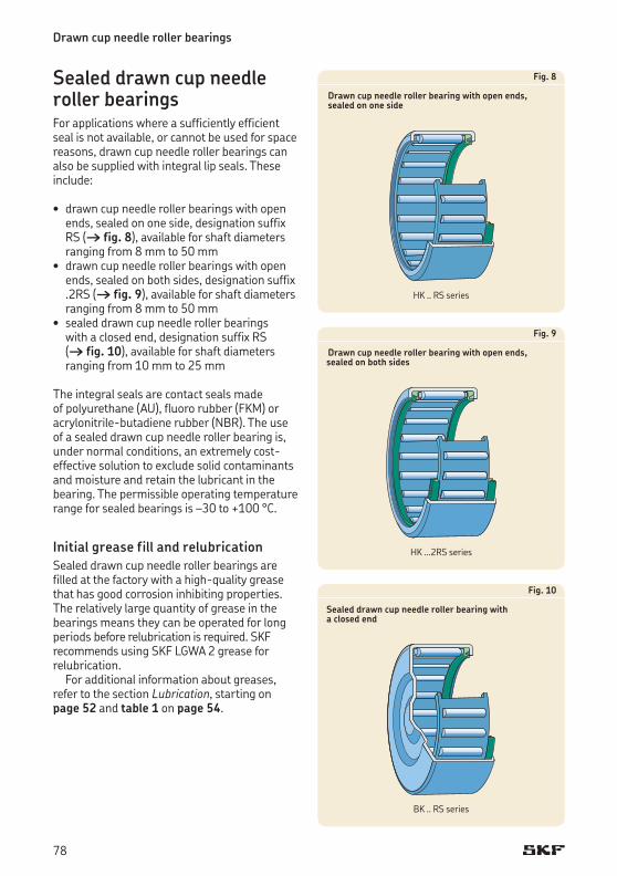
Sealed drawn cup needle roller bearingsFor applications where a sufficiently efficient seal is not available, or cannot be used for space reasons, drawn cup needle roller bearings can also be supplied with integral lip seals. These include:
• drawncupneedlerollerbearingswithopenends, sealed on one side, designation suffix RS († fig. 8), available for shaft diameters ranging from 8 mm to 50 mm• drawncupneedlerollerbearingswithopen
ends, sealed on both sides, designation suffix .2RS († fig. 9), available for shaft diameters ranging from 8 mm to 50 mm• sealeddrawncupneedlerollerbearings
with a closed end, designation suffix RS († fig. 10), available for shaft diameters ranging from 10 mm to 25 mm
The integral seals are contact seals made of polyurethane (AU), fluoro rubber (FKM) or acrylonitrile-butadiene rubber (NBR). The use of a sealed drawn cup needle roller bearing is, under normal conditions, an extremely cost- effective solution to exclude solid contaminants and moisture and retain the lubricant in the bearing. The permissible operating temperature range for sealed bearings is –30 to +100 °C.
Initial grease fill and relubricationSealed drawn cup needle roller bearings are filled at the factory with a high-quality grease that has good corrosion inhibiting properties. The relatively large quantity of grease in the bearings means they can be operated for long periods before relubrication is required. SKF recommends using SKF LGWA 2 grease for relubrication.
For additional information about greases, refer to the section Lubrication, starting on page 52 and table 1 on page 54.
Fig. 9
Drawn cup needle roller bearing with open ends, sealed on both sides
Fig. 8
Drawn cup needle roller bearing with open ends, sealed on one side
Fig. 10
Sealed drawn cup needle roller bearing with a closed end
Drawn cup needle roller bearings
HK..RSseries
HK...2RSseries
BK .. RS series
78
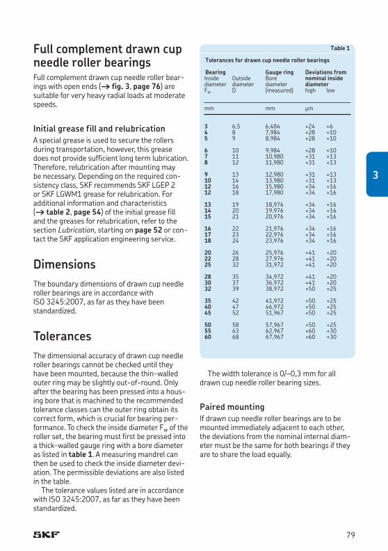
Full complement drawn cup needle roller bearingsFull complement drawn cup needle roller bear-ings with open ends († fig. 3, page 76) are suitable for very heavy radial loads at moderate speeds.
Initial grease fill and relubricationA special grease is used to secure the rollers during transportation, however, this grease does not provide sufficient long term lubri cation. Therefore, relubrication after mounting may be necessary. Depending on the required con-sistency class, SKF recommends SKF LGEP 2 or SKF LGWM1 grease for relubrication. For additional information and characteristics († table 2, page 54) of the initial grease fill and the greases for relubrication, refer to the section Lubrication, starting on page 52 or con-tact the SKF application engineering service.
DimensionsThe boundary dimensions of drawn cup needle roller bearings are in accordance with ISO 3245:2007, as far as they have been standardized.
TolerancesThe dimensional accuracy of drawn cup needle roller bearings cannot be checked until they have been mounted, because the thin-walled outer ring may be slightly out-of-round. Only after the bearing has been pressed into a hous-ing bore that is machined to the recommended tolerance classes can the outer ring obtain its correct form, which is crucial for bearing per-formance. To check the inside diameter Fw of the roller set, the bearing must first be pressed into a thick-walled gauge ring with a bore diameter as listed in table 1. A measuring mandrel can then be used to check the inside diameter devi-ation. The permissible deviations are also listed in the table.
The tolerance values listed are in accordance with ISO 3245:2007, as far as they have been standardized.
The width tolerance is 0/–0,3 mm for all drawn cup needle roller bearing sizes.
Paired mountingIf drawn cup needle roller bearings are to be mountedimmediatelyadjacenttoeachother,the deviations from the nominal internal diam-eter must be the same for both bearings if they are to share the load equally.
Table 1
Tolerances for drawn cup needle roller bearings
Bearing Gauge ring Deviations fromInside Outside Bore nominal insidediameter diameter diameter diameterFw D (measured) high low
mm mm μm
3 6,5 6,484 +24 +64 8 7,984 +28 +105 9 8,984 +28 +10
6 10 9,984 +28 +107 11 10,980 +31 +138 12 11,980 +31 +13
9 13 12,980 +31 +1310 14 13,980 +31 +1312 16 15,980 +34 +1612 18 17,980 +34 +16
13 19 18,976 +34 +1614 20 19,976 +34 +1615 21 20,976 +34 +16
16 22 21,976 +34 +1617 23 22,976 +34 +1618 24 23,976 +34 +16
20 26 25,976 +41 +2022 28 27,976 +41 +2025 32 31,972 +41 +20
28 35 34,972 +41 +2030 37 36,972 +41 +2032 39 38,972 +50 +25
35 42 41,972 +50 +2540 47 46,972 +50 +2545 52 51,967 +50 +25
50 58 57,967 +50 +2555 63 62,967 +60 +3060 68 67,967 +60 +30
79
3
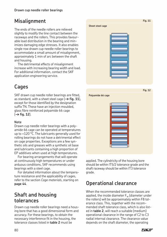
MisalignmentThe ends of the needle rollers are relieved slightly to modify the line contact between the raceways and the rollers. This provides favour-able load distribution in the bearing and min-imizes damaging edge stresses. It also enables single row drawn cup needle roller bearings to accommodate a small amount of misalignment, approximately 1 min of arc between the shaft and housing.
The detrimental effects of misalignment increase with increasing bearing width and load. For additional information, contact the SKF application engineering service.
CagesSKF drawn cup needle roller bearings are fitted, as standard, with a sheet steel cage († fig. 11), except for those identified by the designation suffixTN.Thesehaveaninjectionmoulded,glass fibre reinforced polyamide 66 cage († fig. 12).
Note Drawn cup needle roller bearings with a poly-amide 66 cage can be operated at temperatures up to +120 °C. The lubricants generally used for rolling bearings do not have a detrimental effect on cage properties. Exceptions are a few syn-thetic oils and greases with a synthetic oil base and lubricants containing a high proportion of EP additives when used at high temperatures.
For bearing arrangements that will operate at continuously high temperatures or under arduous conditions, SKF recommends using bearings with a steel cage.
For detailed information about the tempera-ture resistance and the applicability of cages, refer to the section Cage materials, starting on page 44.
Shaft and housing tolerancesDrawn cup needle roller bearings need a hous-ing bore that has a good dimensional form and accuracy. For these bearings, to obtain the ne cessary interference fit in the housing, the tolerance classes listed in table 2 must be
Fig. 11
Sheet steel cage
Fig. 12
Polyamide 66 cage
Drawn cup needle roller bearings
applied. The cylindricity of the housing bore should be within IT5/2 tolerance grade and the shaft raceway should be within IT3 tolerance grade.
Operational clearanceWhen the recommended tolerance classes are applied, the inside diameter Fw (diameter under the rollers) will be approximately within F8 tol-erance class. This, together with the recom-mended shaft tolerance class, which is also list-ed in table 2, will reach a suitable (medium) oper ational clearance in the range of C2 to C3 radial internal clearance. The clearance value depends on the shaft diameter, the operating
80
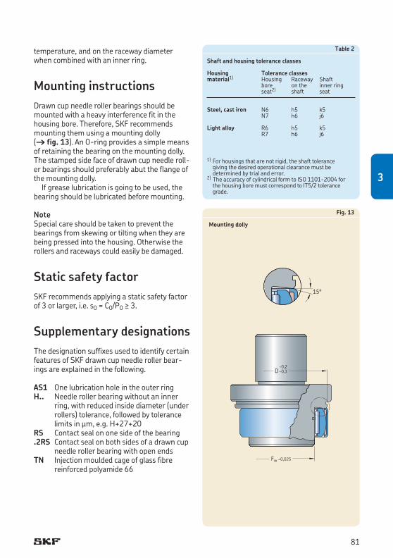
temperature, and on the raceway diameter when combined with an inner ring.
Mounting instructionsDrawn cup needle roller bearings should be mounted with a heavy interference fit in the housing bore. Therefore, SKF recommends mounting them using a mounting dolly († fig. 13). An O-ring provides a simple means of retaining the bearing on the mounting dolly. The stamped side face of drawn cup needle roll-er bearings should preferably abut the flange of the mounting dolly.
If grease lubrication is going to be used, the bearing should be lubricated before mounting.
NoteSpecial care should be taken to prevent the bearings from skewing or tilting when they are being pressed into the housing. Otherwise the rollers and raceways could easily be damaged.
Static safety factorSKF recommends applying a static safety factor of 3 or larger, i.e. s0 = C0/P0 ≥ 3.
Supplementary designationsThe designation suffixes used to identify certain features of SKF drawn cup needle roller bear-ings are explained in the following.
AS1 One lubrication hole in the outer ringH.. Needle roller bearing without an inner
ring, with reduced inside diameter (under rollers) tolerance, followed by tolerance limits in μm, e.g. H+27+20
RS Contact seal on one side of the bearing.2RS Contact seal on both sides of a drawn cup
needle roller bearing with open endsTN Injectionmouldedcageofglassfibre
re inforced polyamide 66
Table 2
Shaft and housing tolerance classes
Housing Tolerance classesmaterial1) Housing Raceway Shaft bore on the inner ring seat2) shaft seat
Steel, cast iron N6 h5 k5 N7 h6 j6
Light alloy R6 h5 k5 R7 h6 j6
1) For housings that are not rigid, the shaft tolerance giving the desired operational clearance must be determined by trial and error.
2) The accuracy of cylindrical form to ISO 1101-2004 for the housing bore must correspond to IT5/2 tolerance grade.
Fig. 13
Mounting dolly
Fw –0,025
D–0,2–0,3
15°
81
3
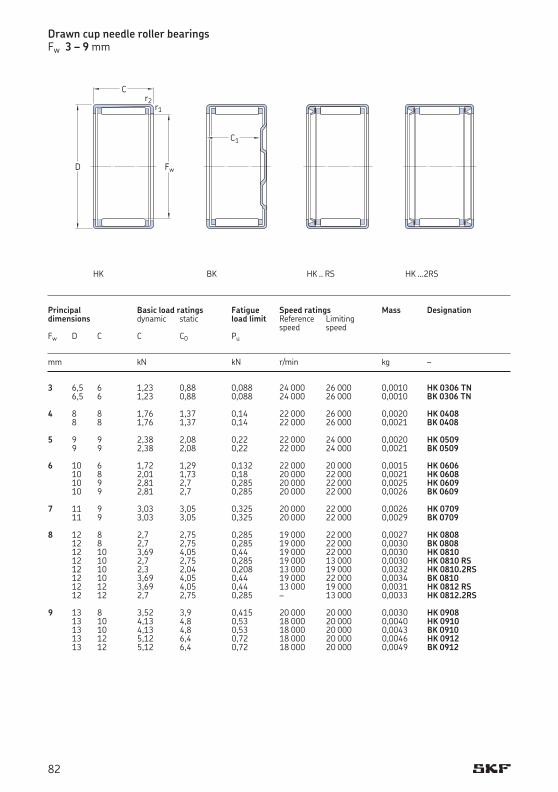
3 6,5 6 1,23 0,88 0,088 24 000 26 000 0,0010 HK 0306 TN 6,5 6 1,23 0,88 0,088 24 000 26 000 0,0010 BK 0306 TN 4 8 8 1,76 1,37 0,14 22 000 26 000 0,0020 HK 0408 8 8 1,76 1,37 0,14 22 000 26 000 0,0021 BK 0408 5 9 9 2,38 2,08 0,22 22 000 24 000 0,0020 HK 0509 9 9 2,38 2,08 0,22 22 000 24 000 0,0021 BK 0509 6 10 6 1,72 1,29 0,132 22 000 20 000 0,0015 HK 0606 10 8 2,01 1,73 0,18 20 000 22 000 0,0021 HK 0608 10 9 2,81 2,7 0,285 20 000 22 000 0,0025 HK 0609 10 9 2,81 2,7 0,285 20 000 22 000 0,0026 BK 0609 7 11 9 3,03 3,05 0,325 20 000 22 000 0,0026 HK 0709 11 9 3,03 3,05 0,325 20 000 22 000 0,0029 BK 0709 8 12 8 2,7 2,75 0,285 19 000 22 000 0,0027 HK 0808 12 8 2,7 2,75 0,285 19 000 22 000 0,0030 BK 0808 12 10 3,69 4,05 0,44 19 000 22 000 0,0030 HK 0810 12 10 2,7 2,75 0,285 19 000 13 000 0,0030 HK 0810 RS 12 10 2,3 2,04 0,208 13 000 19 000 0,0032 HK 0810.2RS 12 10 3,69 4,05 0,44 19 000 22 000 0,0034 BK 0810 12 12 3,69 4,05 0,44 13 000 19 000 0,0031 HK 0812 RS 12 12 2,7 2,75 0,285 – 13 000 0,0033 HK 0812.2RS 9 13 8 3,52 3,9 0,415 20 000 20 000 0,0030 HK 0908 13 10 4,13 4,8 0,53 18 000 20 000 0,0040 HK 0910 13 10 4,13 4,8 0,53 18 000 20 000 0,0043 BK 0910 13 12 5,12 6,4 0,72 18 000 20 000 0,0046 HK 0912 13 12 5,12 6,4 0,72 18 000 20 000 0,0049 BK 0912
Drawn cup needle roller bearingsFw 3 – 9 mm
Principal Basic load ratings Fatigue Speed ratings Mass Designationdimensions dynamic static load limit Reference Limiting speed speed Fw D C C C0 Pu
mm kN kN r/min kg –
Fw
C
D
r2r1
HK HK...2RS
C1
BK HK..RS
82
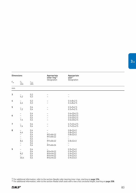
3 – 0,3 – – 5,2 0,3 – – 4 – 0,3 – G 4¥8¥2 S 6,4 0,3 – G 4¥8¥2 S 5 – 0,4 – G 5¥9¥2 S 7,2 0,4 – G 5¥9¥2 S – 0,4 – G 6¥10¥2 S6 – 0,4 – G 6¥10¥2 S – 0,4 – G 6¥10¥2 S 7,4 0,4 – G 6¥10¥2 S 7 – 0,4 – G 7¥11¥2 S 7,4 0,4 – G 7¥11¥2 S 8 – 0,4 – G 8¥12¥3 6,4 0,4 – G 8¥12¥3 – 0,4 IR 5¥8¥12 G 8¥12¥3 – 0,4 IR 5¥8¥12 – – 0,4 – – 8,4 0,4 IR 5¥8¥12 G 8¥12¥3 – 0,4 – – – 0,4 IR 5¥8¥16 – 9 – 0,4 – G 9¥13¥3 – 0,4 IR 6¥9¥12 G 9¥13¥3 8,2 0,4 IR 6¥9¥12 G 9¥13¥3 – 0,4 IR 6¥9¥12 G 9¥13¥3 10,4 0,4 IR 6¥9¥12 G 9¥13¥3
Dimensions Appropriate Appropriate inner ring1) seal2)
Designation DesignationFw C1 r1,2 min min
mm
1) For additional information, refer to the section Needle roller bearing inner rings, starting on page 196.2) For additional information, refer to the section Radial shaft seals with a low cross sectional height, starting on page 208.
83
3.1
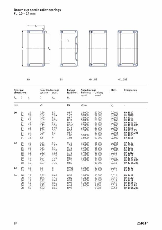
10 14 10 4,29 5,3 0,57 18 000 20 000 0,0041 HK 1010 14 10 6,82 11,4 1,27 18 000 14 000 0,0046 HN 1010 14 10 4,29 5,3 0,57 18 000 20 000 0,0043 BK 1010 14 12 5,39 6,95 0,78 18 000 20 000 0,0048 HK 1012 14 12 4,29 5,3 0,57 18 000 12 000 0,0042 HK 1012 RS 14 12 3,19 3,55 0,365 12 000 18 000 0,0043 HK 1012.2RS 14 12 5,39 6,95 0,78 18 000 20 000 0,0050 BK 1012 14 12 4,29 5,3 0,57 12 000 18 000 0,0043 BK 1012 RS 14 14 4,29 5,3 0,57 – 12 000 0,0046 HK 1014.2RS 14 15 6,6 9 1,02 18 000 20 000 0,0060 HK 1015 14 15 6,6 9 1,02 18 000 20 000 0,0062 BK 1015 12 16 10 4,84 6,4 0,71 16 000 18 000 0,0046 HK 1210 16 10 7,48 13,7 1,53 17 000 13 000 0,0053 HN 1210 16 10 4,84 6,4 0,71 16 000 18 000 0,0052 BK 1210 18 12 6,27 7,35 0,85 16 000 18 000 0,0090 HK 1212 18 12 9,52 15,3 1,76 17 000 13 000 0,011 HN 1212 18 12 6,27 7,35 0,85 16 000 18 000 0,010 BK 1212 18 14 6,27 7,35 0,85 16 000 10 000 0,010 HK 1214 RS 16 14 4,84 6,4 0,71 10 000 16 000 0,0080 HK 1214.2RS 18 16 6,27 7,35 0,85 – 10 000 0,011 HK 1216.2RS 13 19 12 6,6 8 0,915 16 000 17 000 0,010 HK 1312 19 12 6,6 8 0,915 16 000 17 000 0,011 BK 1312 14 20 12 6,82 8,65 0,98 15 000 17 000 0,011 HK 1412 20 12 10,5 17,6 2,04 15 000 12 000 0,012 HN 1412 20 12 6,82 8,65 0,98 15 000 17 000 0,012 BK 1412 20 14 6,82 8,65 0,98 15 000 9 500 0,012 HK 1414 RS 20 14 6,82 8,65 0,98 15 000 9 500 0,013 BK 1414 RS 20 16 6,82 8,65 0,98 – 9 500 0,013 HK 1416.2RS
Principal Basic load ratings Fatigue Speed ratings Mass Designationdimensions dynamic static load limit Reference Limiting speed speed Fw D C C C0 Pu
mm kN kN r/min kg –
Drawn cup needle roller bearingsFw 10 – 14 mm
HK...2RS
Fw
C
D
r2r1
HK
C1
BK HK..RS
84
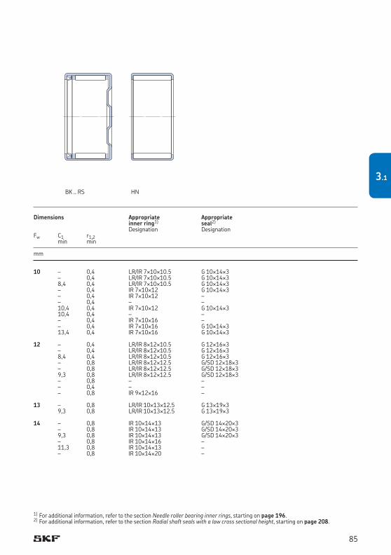
10 – 0,4 LR/IR 7¥10¥10.5 G 10¥14¥3 – 0,4 LR/IR 7¥10¥10.5 G 10¥14¥3 8,4 0,4 LR/IR 7¥10¥10.5 G 10¥14¥3 – 0,4 IR 7¥10¥12 G 10¥14¥3 – 0,4 IR 7¥10¥12 – – 0,4 – – 10,4 0,4 IR 7¥10¥12 G 10¥14¥3 10,4 0,4 – – – 0,4 IR 7¥10¥16 – – 0,4 IR 7¥10¥16 G 10¥14¥3 13,4 0,4 IR 7¥10¥16 G 10¥14¥3 12 – 0,4 LR/IR 8¥12¥10.5 G 12¥16¥3 – 0,4 LR/IR 8¥12¥10.5 G 12¥16¥3 8,4 0,4 LR/IR 8¥12¥10.5 G 12¥16¥3 – 0,8 LR/IR 8¥12¥12.5 G/SD 12¥18¥3 – 0,8 LR/IR 8¥12¥12.5 G/SD 12¥18¥3 9,3 0,8 LR/IR 8¥12¥12.5 G/SD 12¥18¥3 – 0,8 – – – 0,4 – – – 0,8 IR 9¥12¥16 – 13 – 0,8 LR/IR 10¥13¥12.5 G 13¥19¥3 9,3 0,8 LR/IR 10¥13¥12.5 G 13¥19¥3 14 – 0,8 IR 10¥14¥13 G/SD 14¥20¥3 – 0,8 IR 10¥14¥13 G/SD 14¥20¥3 9,3 0,8 IR 10¥14¥13 G/SD 14¥20¥3 – 0,8 IR 10¥14¥16 – 11,3 0,8 IR 10¥14¥13 – – 0,8 IR 10¥14¥20 –
1) For additional information, refer to the section Needle roller bearing inner rings, starting on page 196.2) For additional information, refer to the section Radial shaft seals with a low cross sectional height, starting on page 208.
Dimensions Appropriate Appropriate inner ring1) seal2)
Designation DesignationFw C1 r1,2 min min
mm
BK .. RS HN
85
3.1
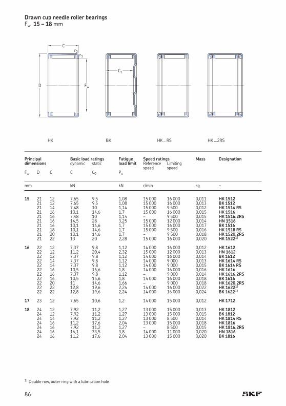
15 21 12 7,65 9,5 1,08 15 000 16 000 0,011 HK 1512 21 12 7,65 9,5 1,08 15 000 16 000 0,013 BK 1512 21 14 7,48 10 1,14 15 000 9 500 0,012 HK 1514 RS 21 16 10,1 14,6 1,7 15 000 16 000 0,015 HK 1516 21 16 7,48 10 1,14 – 9 500 0,015 HK 1516.2RS 21 16 14,5 28 3,25 15 000 12 000 0,014 HN 1516 21 16 10,1 14,6 1,7 15 000 16 000 0,017 BK 1516 21 18 10,1 14,6 1,7 15 000 9 500 0,016 HK 1518 RS 21 20 10,1 14,6 1,7 – 9 500 0,018 HK 1520.2RS 21 22 13 20 2,28 15 000 16 000 0,020 HK 15221)
16 22 12 7,37 9,8 1,12 14 000 16 000 0,012 HK 1612 22 12 11,2 20,4 2,32 15 000 12 000 0,013 HN 1612 22 12 7,37 9,8 1,12 14 000 16 000 0,014 BK 1612 22 14 7,37 9,8 1,12 14 000 9 000 0,013 HK 1614 RS 22 14 7,37 9,8 1,12 14 000 9 000 0,015 BK 1614 RS 22 16 10,5 15,6 1,8 14 000 16 000 0,016 HK 1616 22 16 7,37 9,8 1,12 – 9 000 0,014 HK 1616.2RS 22 16 10,5 15,6 1,8 14 000 16 000 0,018 BK 1616 22 20 11 14,6 1,66 – 9 000 0,018 HK 1620.2RS 22 22 12,8 19,6 2,24 14 000 16 000 0,022 HK 16221)
22 22 12,8 19,6 2,24 14 000 16 000 0,024 BK 16221)
17 23 12 7,65 10,6 1,2 14 000 15 000 0,012 HK 1712 18 24 12 7,92 11,2 1,27 13 000 15 000 0,013 HK 1812 24 12 7,92 11,2 1,27 13 000 15 000 0,015 BK 1812 24 14 7,92 11,2 1,27 13 000 8 500 0,014 HK 1814 RS 24 16 11,2 17,6 2,04 13 000 15 000 0,018 HK 1816 24 16 7,92 11,2 1,27 – 8 500 0,015 HK 1816.2RS 24 16 16,1 33,5 3,8 14 000 11 000 0,020 HN 1816 24 16 11,2 17,6 2,04 13 000 15 000 0,020 BK 1816
1) Double row, outer ring with a lubrication hole
Principal Basic load ratings Fatigue Speed ratings Mass Designationdimensions dynamic static load limit Reference Limiting speed speed Fw D C C C0 Pu
mm kN kN r/min kg –
Drawn cup needle roller bearingsFw 15 – 18 mm
HK...2RS
Fw
C
D
r2r1
HK
C1
BK HK..RS
86

15 – 0,8 LR/IR 12¥15¥12.5 G/SD 15¥21¥3 9,3 0,8 LR/IR 12¥15¥12.5 G/SD 15¥21¥3 – 0,8 LR/IR 12¥15¥16.5 – – 0,8 LR/IR 12¥15¥16.5 G/SD 15¥21¥3 – 0,8 LR/IR 12¥15¥16.5 – – 0,8 LR/IR 12¥15¥16.5 G/SD 15¥21¥3 13,3 0,8 LR/IR 12¥15¥16.5 G/SD 15¥21¥3 – 0,8 – – – 0,8 LR/IR 12¥15¥22.5 – – 0,8 LR/IR 12¥15¥22.5 G/SD 15¥21¥3 16 – 0,8 IR 12¥16¥13 G/SD 16¥22¥3 – 0,8 IR 12¥16¥13 G/SD 16¥22¥3 9,3 0,8 IR 12¥16¥13 G/SD 16¥22¥3 – 0,8 IR 12¥16¥16 – 11,3 0,8 IR 12¥16¥13 – – 0,8 IR 12¥16¥16 G/SD 16¥22¥3 – 0,8 IR 12¥16¥20 – 13,3 0,8 IR 12¥16¥16 G/SD 16¥22¥3 – 0,8 IR 12¥16¥22 – – 0,8 IR 12¥16¥22 G/SD 16¥22¥3 19,3 0,8 IR 12¥16¥22 G/SD 16¥22¥3 17 – 0,8 – G/SD 17¥23¥3 18 – 0,8 LR 15¥18¥12.5 G/SD 18¥24¥3 9,3 0,8 LR 15¥18¥12.5 G/SD 18¥24¥3 – 0,8 LR/IR 15¥18¥16.5 – – 0,8 LR/IR 15¥18¥16.5 G/SD 18¥24¥3 – 0,8 LR/IR 15¥18¥16.5 – – 0,8 LR/IR 15¥18¥16.5 G/SD 18¥24¥3 13,3 0,8 LR/IR 15¥18¥16.5 G/SD 18¥24¥3
Dimensions Appropriate Appropriate inner ring1) seal2)
Designation DesignationFw C1 r1,2 min min
mm
1) For additional information, refer to the section Needle roller bearing inner rings, starting on page 196.2) For additional information, refer to the section Radial shaft seals with a low cross sectional height, starting on page 208.
HK(double row)
BK(double row)
BK .. RS HN
87
3.1
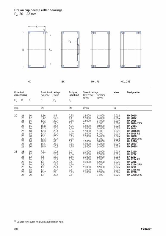
20 26 10 6,16 8,5 0,93 12 000 14 000 0,012 HK 2010 26 12 8,42 12,5 1,4 12 000 14 000 0,014 HK 2012 26 16 12,3 20,4 2,36 12 000 14 000 0,019 HK 2016 26 16 8,42 12,5 1,4 – 8 000 0,018 HK 2016.2RS 26 16 16,8 36,5 4,25 12 000 10 000 0,022 HN 2016 26 16 12,3 20,4 2,36 12 000 14 000 0,022 BK 2016 26 18 12,3 20,4 2,36 12 000 8 000 0,021 HK 2018 RS 26 18 12,3 20,4 2,36 12 000 8 000 0,024 BK 2018 RS 26 20 15,1 26,5 3,15 12 000 14 000 0,024 HK 2020 26 20 12,3 20,4 2,36 – 8 000 0,023 HK 2020.2RS 26 20 20,9 48 5,7 12 000 10 000 0,030 HN 2020 26 20 15,1 26,5 3,15 12 000 14 000 0,027 BK 20201)
26 30 20,9 40,5 4,75 12 000 14 000 0,035 HK 20301)
22 28 10 7,21 10,6 1,2 11 000 12 000 0,013 HK 2210 28 12 8,8 13,7 1,56 11 000 12 000 0,015 HK 2212 28 12 8,8 13,7 1,56 11 000 12 000 0,018 BK 2212 28 14 8,8 13,7 1,56 11 000 7 500 0,016 HK 2214 RS 28 16 13 22,4 2,6 11 000 12 000 0,021 HK 2216 28 16 8,8 13,7 1,56 – 7 500 0,018 HK 2216.2RS 28 16 13 22,4 2,6 11 000 12 000 0,024 BK 2216 28 18 13 22,4 2,6 11 000 7 500 0,024 HK 2218 RS 28 20 15,7 29 3,45 11 000 12 000 0,026 HK 2220 28 20 13 22,4 2,6 – 7 500 0,026 HK 2220.2RS
Principal Basic load ratings Fatigue Speed ratings Mass Designationdimensions dynamic static load limit Reference Limiting speed speed Fw D C C C0 Pu
mm kN kN r/min kg –
Drawn cup needle roller bearingsFw 20 – 22 mm
1) Double row, outer ring with a lubrication hole
HK...2RS
Fw
C
D
r2r1
HK
C1
BK HK..RS
88
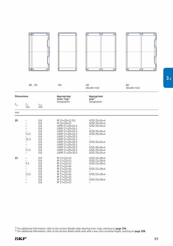
20 – 0,8 IR 15¥20¥12 IS1 G/SD 20¥26¥4 – 0,8 IR 15¥20¥13 G/SD 20¥26¥4 – 0,8 LR/IR 17¥20¥16.5 G/SD 20¥26¥4 – 0,8 LR/IR 17¥20¥16.5 – – 0,8 LR/IR 17¥20¥16.5 G/SD 20¥26¥4 13,3 0,8 LR/IR 17¥20¥16.5 G/SD 20¥26¥4 – 0,8 LR/IR 17¥20¥20.5 – 15,3 0,8 LR/IR 17¥20¥16.5 – – 0,8 LR/IR 17¥20¥20.5 G/SD 20¥26¥4 – 0,8 LR/IR 17¥20¥20.5 – – 0,8 LR/IR 17¥20¥20.5 G/SD 20¥26¥4 17,3 0,8 LR/IR 17¥20¥20.5 G/SD 20¥26¥4 – 0,8 LR/IR 17¥20¥30.5 G/SD 20¥26¥4 22 – 0,8 IR 17¥22¥13 G/SD 22¥28¥4 – 0,8 IR 17¥22¥13 G/SD 22¥28¥4 9,3 0,8 IR 17¥22¥13 G/SD 22¥28¥4 – 0,8 IR 17¥22¥16 – – 0,8 IR 17¥22¥16 G/SD 22¥28¥4 – 0,8 IR 17¥22¥23 – 13,3 0,8 IR 17¥22¥16 G/SD 22¥28¥4 – 0,8 IR 17¥22¥23 – – 0,8 IR 17¥22¥23 G/SD 22¥28¥4 – 0,8 IR 17¥22¥23 –
Dimensions Appropriate Appropriate inner ring1) seal2)
Designation DesignationFw C1 r1,2 min min
mm
1) For additional information, refer to the section Needle roller bearing inner rings, starting on page 196.2) For additional information, refer to the section Radial shaft seals with a low cross sectional height, starting on page 208.
HK(double row)
BK(double row)
BK .. RS HN
89
3.1
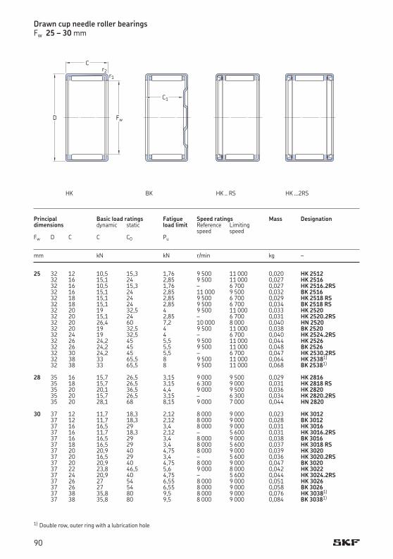
25 32 12 10,5 15,3 1,76 9 500 11 000 0,020 HK 2512 32 16 15,1 24 2,85 9 500 11 000 0,027 HK 2516 32 16 10,5 15,3 1,76 – 6 700 0,027 HK 2516.2RS 32 16 15,1 24 2,85 11 000 9 500 0,032 BK 2516 32 18 15,1 24 2,85 9 500 6 700 0,029 HK 2518 RS 32 18 15,1 24 2,85 9 500 6 700 0,034 BK 2518 RS 32 20 19 32,5 4 9 500 11 000 0,033 HK 2520 32 20 15,1 24 2,85 – 6 700 0,031 HK 2520.2RS 32 20 26,4 60 7,2 10 000 8 000 0,040 HN 2520 32 20 19 32,5 4 9 500 11 000 0,038 BK 2520 32 24 19 32,5 4 – 6 700 0,040 HK 2524.2RS 32 26 24,2 45 5,5 9 500 11 000 0,044 HK 2526 32 26 24,2 45 5,5 9 500 11 000 0,048 BK 2526 32 30 24,2 45 5,5 – 6 700 0,047 HK 2530.2RS 32 38 33 65,5 8 9 500 11 000 0,064 HK 25381)
32 38 33 65,5 8 9 500 11 000 0,068 BK 25381)
28 35 16 15,7 26,5 3,15 9 000 9 500 0,029 HK 2816 35 18 15,7 26,5 3,15 6 300 9 000 0,031 HK 2818 RS 35 20 20,1 36,5 4,4 9 000 9 500 0,036 HK 2820 35 20 15,7 26,5 3,15 – 6 300 0,034 HK 2820.2RS 35 20 28,1 68 8,15 9 000 7 000 0,044 HN 2820 30 37 12 11,7 18,3 2,12 8 000 9 000 0,023 HK 3012 37 12 11,7 18,3 2,12 8 000 9 000 0,028 BK 3012 37 16 16,5 29 3,4 8 000 9 000 0,031 HK 3016 37 16 11,7 18,3 2,12 – 5 600 0,031 HK 3016.2RS 37 16 16,5 29 3,4 8 000 9 000 0,038 BK 3016 37 18 16,5 29 3,4 8 000 5 600 0,037 HK 3018 RS 37 20 20,9 40 4,75 8 000 9 000 0,039 HK 3020 37 20 16,5 29 3,4 – 5 600 0,036 HK 3020.2RS 37 20 20,9 40 4,75 8 000 9 000 0,047 BK 3020 37 22 23,8 46,5 5,6 9 000 8 000 0,042 HK 3022 37 24 20,9 40 4,75 – 5 600 0,044 HK 3024.2RS 37 26 27 54 6,55 8 000 9 000 0,051 HK 3026 37 26 27 54 6,55 8 000 9 000 0,058 BK 3026 37 38 35,8 80 9,5 8 000 9 000 0,076 HK 30381)
37 38 35,8 80 9,5 8 000 9 000 0,084 BK 30381)
Principal Basic load ratings Fatigue Speed ratings Mass Designationdimensions dynamic static load limit Reference Limiting speed speed Fw D C C C0 Pu
mm kN kN r/min kg –
Drawn cup needle roller bearingsFw 25 – 30 mm
1) Double row, outer ring with a lubrication hole
HK...2RS
Fw
C
D
r2r1
HK
C1
BK HK..RS
90
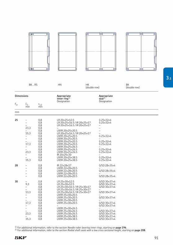
25 – 0,8 LR 20¥25¥12.5 G 25¥32¥4 – 0,8 LR 20¥25¥16.5 / IR 20¥25¥17 G 25¥32¥4 – 0,8 LR 20¥25¥16.5 / IR 20¥25¥17 – 23,3 0,8 – – – 0,8 LR/IR 20¥25¥20.5 – 15,3 0,8 LR 20¥25¥16.5 / IR 20¥25¥17 – – 0,8 LR/IR 20¥25¥20.5 G 25¥32¥4 – 0,8 LR/IR 20¥25¥20.5 – – 0,8 LR/IR 20¥25¥20.5 G 25¥32¥4 17,3 0,8 LR/IR 20¥25¥20.5 G 25¥32¥4 – 0,8 LR/IR 20¥25¥26.5 – – 0,8 LR/IR 20¥25¥26.5 G 25¥32¥4 23,3 0,8 LR/IR 20¥25¥26.5 G 25¥32¥4 – 0,8 IR 20¥25¥30 – – 0,8 LR/IR 20¥25¥38.5 G 25¥32¥4 35,3 0,8 LR/IR 20¥25¥38.5 G 25¥32¥4 28 – 0,8 IR 22¥28¥17 G/SD 28¥35¥4 – 0,8 LR/IR 22¥28¥20.5 – – 0,8 LR/IR 22¥28¥20.5 G/SD 28¥35¥4 – 0,8 LR/IR 22¥28¥20.5 – – 0,8 LR/IR 22¥28¥20.5 G/SD 28¥35¥4 30 – 0,8 LR 25¥30¥12.5 G/SD 30¥37¥4 9,3 0,8 LR 25¥30¥12.5 G/SD 30¥37¥4 – 0,8 LR 25¥30¥16.5 / IR 25¥30¥17 G/SD 30¥37¥4 – 0,8 LR 25¥30¥16.5 / IR 25¥30¥17 – 13,3 0,8 LR 25¥30¥16.5 / IR 25¥30¥17 G/SD 30¥37¥4 – 0,8 LR/IR 25¥30¥20.5 – – 0,8 LR/IR 25¥30¥20.5 G/SD 30¥37¥4 – 0,8 LR/IR 25¥30¥20.5 – 17,3 0,8 LR/IR 25¥30¥20.5 G/SD 30¥37¥4 – 0,8 – G/SD 30¥37¥4 – 0,8 LR/IR 25¥30¥26.5 – – 0,8 LR/IR 25¥30¥26.5 G/SD 30¥37¥4 23,3 0,8 LR/IR 25¥30¥26.5 G/SD 30¥37¥4 – 0,8 LR/IR 25¥30¥38.5 G/SD 30¥37¥4 35,3 0,8 LR/IR 25¥30¥38.5 G/SD 30¥37¥4
Dimensions Appropriate Appropriate inner ring1) seal2)
Designation DesignationFw C1 r1,2 min min
mm
1) For additional information, refer to the section Needle roller bearing inner rings, starting on page 196.2) For additional information, refer to the section Radial shaft seals with a low cross sectional height, starting on page 208.
HK(double row)
BK(double row)
BK .. RS HN
91
3.1
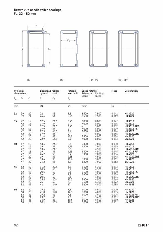
Drawn cup needle roller bearingsFw 32 – 50 mm
32 39 20 22 43 5,2 8 500 7 500 0,041 HK 3220 39 24 26,4 54 6,55 8 500 7 500 0,049 HK 3224 35 42 12 12,5 21,6 2,45 7 000 8 000 0,027 HK 3512 42 16 17,9 34 4 7 000 8 000 0,036 HK 3516 42 16 12,5 21,6 2,45 – 5 000 0,032 HK 3516.2RS 42 18 17,9 34 4 7 000 5 000 0,039 HK 3518 RS 42 20 22,9 46,5 5,6 7 000 8 000 0,044 HK 3520 42 20 17,9 34 4 – 5 000 0,041 HK 3520.2RS 42 20 31,4 83 10,2 7 500 6 000 0,054 HN 3520 42 20 22,9 46,5 5,6 7 000 8 000 0,053 BK 3520 40 47 12 13,4 24,5 2,8 6 300 7 000 0,030 HK 4012 47 16 19 39 4,55 6 300 7 000 0,039 HK 4016 47 16 13,4 24,5 2,8 – 4 500 0,037 HK 4016.2RS 47 18 19 39 4,55 6 300 4 500 0,045 HK 4018 RS 47 20 24,2 53 6,4 6 300 7 000 0,054 HK 4020 47 20 19 39 4,55 – 4 500 0,048 HK 4020.2RS 47 20 33,6 95 11,6 6 300 5 000 0,061 HN 4020 47 20 24,2 53 6,4 6 300 7 000 0,062 BK 4020 45 52 12 14,2 27,5 3,2 5 600 6 300 0,033 HK 4512 52 16 20,5 43 5,1 5 600 6 300 0,046 HK 4516 52 18 20,5 43 5,1 5 600 4 000 0,050 HK 4518 RS 52 20 26 60 7,2 5 600 6 300 0,056 HK 4520 52 20 20,5 43 5,1 – 4 000 0,054 HK 4520.2RS 52 20 35,8 108 13,2 5 600 4 500 0,066 HN 4520 52 20 26 60 7,2 5 600 6 300 0,072 BK 4520 52 25 44 140 17 5 600 4 500 0,085 HN 4525 50 58 20 29,2 63 7,8 5 000 5 600 0,070 HK 5020 58 20 41,8 120 14,3 5 000 4 000 0,085 HN 5020 58 22 29,2 63 7,8 5 000 3 600 0,076 HK 5022 RS 58 24 29,2 63 7,8 – 3 600 0,081 HK 5024.2RS 58 25 36,9 85 10,6 5 000 5 600 0,090 HK 5025 58 25 50,1 153 18,6 5 000 4 000 0,11 HN 5025
Principal Basic load ratings Fatigue Speed ratings Mass Designationdimensions dynamic static load limit Reference Limiting speed speed Fw D C C C0 Pu
mm kN kN r/min kg –
C1
BK HK..RS HK...2RS
Fw
C
D
r2r1
HK
92
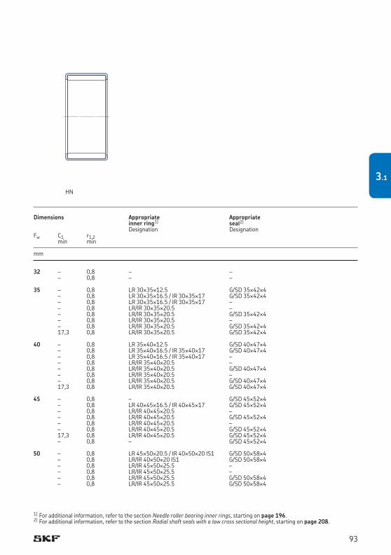
32 – 0,8 – – – 0,8 – – 35 – 0,8 LR 30¥35¥12.5 G/SD 35¥42¥4 – 0,8 LR 30¥35¥16.5 / IR 30¥35¥17 G/SD 35¥42¥4 – 0,8 LR 30¥35¥16.5 / IR 30¥35¥17 – – 0,8 LR/IR 30¥35¥20.5 – – 0,8 LR/IR 30¥35¥20.5 G/SD 35¥42¥4 – 0,8 LR/IR 30¥35¥20.5 – – 0,8 LR/IR 30¥35¥20.5 G/SD 35¥42¥4 17,3 0,8 LR/IR 30¥35¥20.5 G/SD 35¥42¥4 40 – 0,8 LR 35¥40¥12.5 G/SD 40¥47¥4 – 0,8 LR 35¥40¥16.5 / IR 35¥40¥17 G/SD 40¥47¥4 – 0,8 LR 35¥40¥16.5 / IR 35¥40¥17 – – 0,8 LR/IR 35¥40¥20.5 – – 0,8 LR/IR 35¥40¥20.5 G/SD 40¥47¥4 – 0,8 LR/IR 35¥40¥20.5 – – 0,8 LR/IR 35¥40¥20.5 G/SD 40¥47¥4 17,3 0,8 LR/IR 35¥40¥20.5 G/SD 40¥47¥4 45 – 0,8 – G/SD 45¥52¥4 – 0,8 LR 40¥45¥16.5 / IR 40¥45¥17 G/SD 45¥52¥4 – 0,8 LR/IR 40¥45¥20.5 – – 0,8 LR/IR 40¥45¥20.5 G/SD 45¥52¥4 – 0,8 LR/IR 40¥45¥20.5 – – 0,8 LR/IR 40¥45¥20.5 G/SD 45¥52¥4 17,3 0,8 LR/IR 40¥45¥20.5 G/SD 45¥52¥4 – 0,8 – G/SD 45¥52¥4 50 – 0,8 LR 45¥50¥20.5 / IR 40¥50¥20 IS1 G/SD 50¥58¥4 – 0,8 LR/IR 40¥50¥20 IS1 G/SD 50¥58¥4 – 0,8 LR/IR 45¥50¥25.5 – – 0,8 LR/IR 45¥50¥25.5 – – 0,8 LR/IR 45¥50¥25.5 G/SD 50¥58¥4 – 0,8 LR/IR 45¥50¥25.5 G/SD 50¥58¥4
Dimensions Appropriate Appropriate inner ring1) seal2)
Designation DesignationFw C1 r1,2 min min
mm
1) For additional information, refer to the section Needle roller bearing inner rings, starting on page 196.2) For additional information, refer to the section Radial shaft seals with a low cross sectional height, starting on page 208.
HN
93
3.1
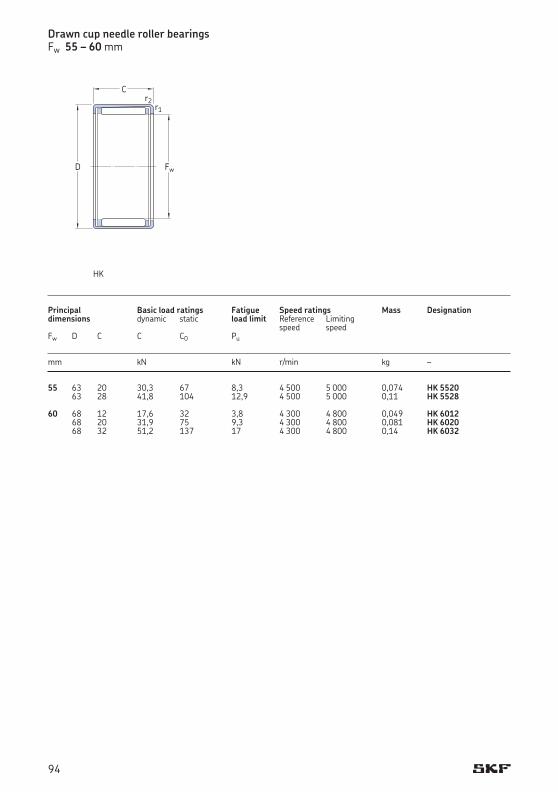
Drawn cup needle roller bearingsFw 55 – 60 mm
Principal Basic load ratings Fatigue Speed ratings Mass Designationdimensions dynamic static load limit Reference Limiting speed speed Fw D C C C0 Pu
mm kN kN r/min kg –
55 63 20 30,3 67 8,3 4 500 5 000 0,074 HK 5520 63 28 41,8 104 12,9 4 500 5 000 0,11 HK 5528 60 68 12 17,6 32 3,8 4 300 4 800 0,049 HK 6012 68 20 31,9 75 9,3 4 300 4 800 0,081 HK 6020 68 32 51,2 137 17 4 300 4 800 0,14 HK 6032
Fw
C
D
r2r1
HK
94
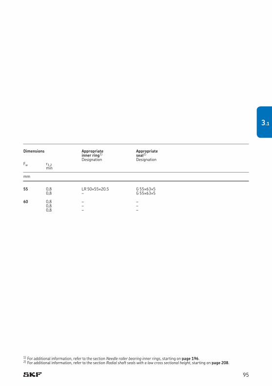
Dimensions Appropriate Appropriate inner ring1) seal2)
Designation DesignationFw r1,2 min
mm
55 0,8 LR 50¥55¥20.5 G 55¥63¥5 0,8 – G 55¥63¥5 60 0,8 – – 0,8 – – 0,8 – –
1) For additional information, refer to the section Needle roller bearing inner rings, starting on page 196.2) For additional information, refer to the section Radial shaft seals with a low cross sectional height, starting on page 208.
95
3.1
Needle roller bearings with machined rings with flanges ........................................... 100
Needle roller bearings with machined rings without flanges ...................................... 102
Dimensions............................................................................................................ 102
Tolerances ............................................................................................................ 102
Internal clearance .................................................................................................. 103
Misalignment ......................................................................................................... 101
Cages .................................................................................................................... 104
Shaft and housing tolerances .................................................................................. 104
Supplementary designations ................................................................................... 105
Product tables ....................................................................................................... 1064.1 Needle roller bearings with machined rings with flanges, without an inner ring .............. 1064.2 Needle roller bearings with machined rings with flanges, with an inner ring ................... 1224.3 Needle roller bearings with machined rings without flanges, without an inner ring ........ 1344.4 Needle roller bearings with machined rings without flanges, with an inner ring .............. 138
Needle roller bearings with machined rings
4
97
4
97
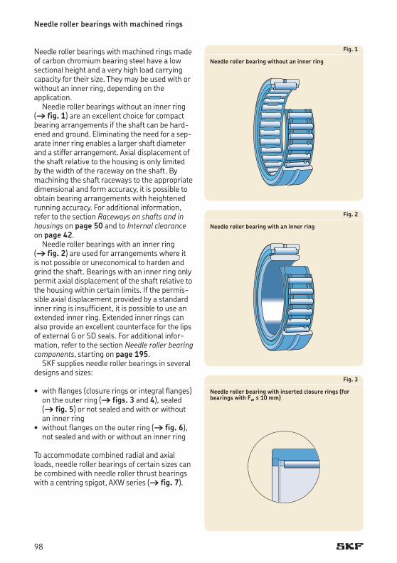
Needle roller bearings with machined rings
Needle roller bearings with machined rings made of carbon chromium bearing steel have a low sectional height and a very high load carrying capacity for their size. They may be used with or without an inner ring, depending on the application.
Needle roller bearings without an inner ring († fig. 1) are an excellent choice for compact bearing arrangements if the shaft can be hard-ened and ground. Eliminating the need for a sep-arate inner ring enables a larger shaft diameter and a stiffer arrangement. Axial displacement of the shaft relative to the housing is only limited by the width of the raceway on the shaft. By machining the shaft raceways to the appropriate dimensional and form accuracy, it is possible to obtain bearing arrangements with heightened running accuracy. For additional information, refer to the section Raceways on shafts and in housings on page 50 and to Internal clearance on page 42.
Needle roller bearings with an inner ring († fig. 2) are used for arrangements where it is not possible or uneconomical to harden and grind the shaft. Bearings with an inner ring only permit axial displacement of the shaft relative to the housing within certain limits. If the permis-sible axial displacement provided by a standard inner ring is insufficient, it is possible to use an extended inner ring. Extended inner rings can also provide an excellent counterface for the lips of external G or SD seals. For add itional infor-mation, refer to the section Needle roller bearing components, starting on page 195.
SKF supplies needle roller bearings in several designs and sizes:
• withflanges(closureringsorintegralflanges)on the outer ring († figs. 3 and 4), sealed († fig. 5) or not sealed and with or without an inner ring• withoutflangesontheouterring(† fig. 6),
not sealed and with or without an inner ring
To accommodate combined radial and axial loads, needle roller bearings of certain sizes can be combined with needle roller thrust bearings with a centring spigot, AXW series († fig. 7).
Fig. 1
Needle roller bearing without an inner ring
Fig. 2
Needle roller bearing with an inner ring
Fig. 3
Needle roller bearing with inserted closure rings (for bearings with Fw ≤ 10 mm)
98
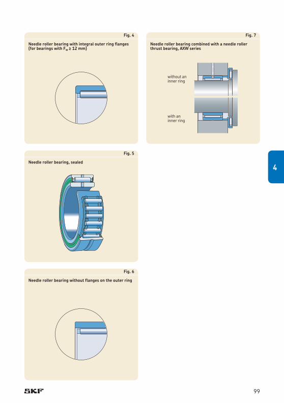
Fig. 4
Needle roller bearing with integral outer ring flanges (for bearings with Fw ≥ 12 mm)
Fig. 5
Needle roller bearing, sealed
Fig. 6
Needle roller bearing without flanges on the outer ring
Fig. 7
Needle roller bearing combined with a needle roller thrust bearing, AXW series
without an inner ring
with aninner ring
99
4
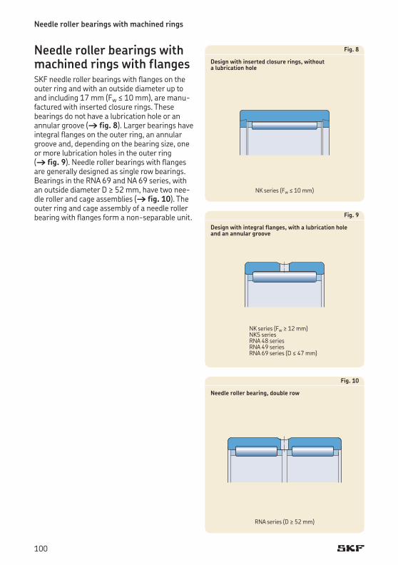
Needle roller bearings with machined rings
Needle roller bearings with machined rings with flangesSKF needle roller bearings with flanges on the outer ring and with an outside diameter up to and including 17 mm (Fw ≤ 10 mm), are manu-factured with inserted closure rings. These bearings do not have a lubrication hole or an annular groove († fig. 8). Larger bearings have integral flanges on the outer ring, an annular groove and, depending on the bearing size, one or more lubrication holes in the outer ring († fig. 9). Needle roller bearings with flanges are generally designed as single row bearings. Bearings in the RNA 69 and NA 69 series, with an outside diameter D ≥ 52 mm, have two nee-dle roller and cage assemblies († fig. 10). The outer ring and cage assembly of a needle roller bearing with flanges form a non-separable unit.
Fig. 8
Design with inserted closure rings, without a lubrication hole
Fig. 9
Design with integral flanges, with a lubrication hole and an annular groove
Fig. 10
Needle roller bearing, double row
NK series (Fw ≤ 10 mm)
NK series (Fw ≥ 12 mm)NKS seriesRNA 48 seriesRNA 49 seriesRNA 69 series (D ≤ 47 mm)
RNA series (D ≥ 52 mm)
100
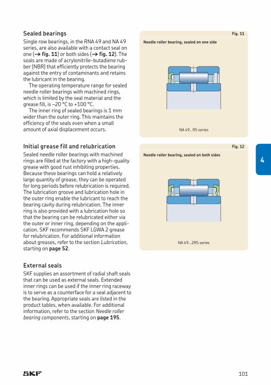
Sealed bearings Single row bearings, in the RNA 49 and NA 49 series, are also available with a contact seal on one († fig. 11) or both sides († fig. 12). The seals are made of acrylonitrile-butadiene rub-ber (NBR) that efficiently protects the bearing against the entry of contaminants and retains the lubricant in the bearing.
The operating temperature range for sealed needle roller bearings with machined rings, which is limited by the seal material and the grease fill, is –20 °C to +100 °C.
The inner ring of sealed bearings is 1 mm wider than the outer ring. This maintains the efficiency of the seals even when a small amount of axial displacement occurs.
Initial grease fill and relubricationSealed needle roller bearings with machined rings are filled at the factory with a high-quality grease with good rust inhibiting properties. Because these bearings can hold a relatively large quantity of grease, they can be operated for long periods before relubrication is required. The lubrication groove and lubrication hole in the outer ring enable the lubricant to reach the bearing cavity during relubrication. The inner ring is also provided with a lubrication hole so that the bearing can be relubricated either via the outer or inner ring, depending on the appli-cation. SKF recommends SKF LGWA 2 grease for relubrication. For additional information about greases, refer to the section Lubrication, starting on page 52.
External sealsSKF supplies an assortment of radial shaft seals that can be used as external seals. Extended inner rings can be used if the inner ring raceway istoserveasacounterfaceforasealadjacenttothe bearing. Appropriate seals are listed in the product tables, when available. For additional information, refer to the section Needle roller bearing components, starting on page 195.
Fig. 11
Needle roller bearing, sealed on one side
Fig. 12
Needle roller bearing, sealed on both sides
NA 49.. RS series
NA 49...2RS series
101
4
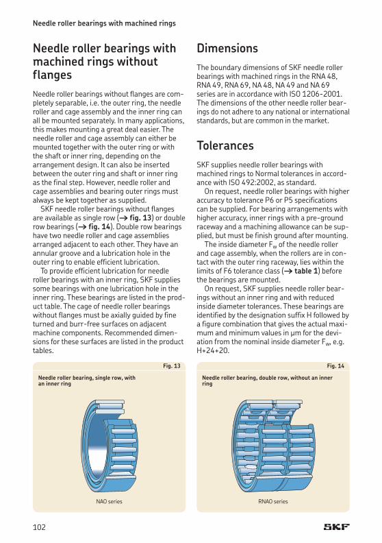
Needle roller bearings with machined rings
Needle roller bearings with machined rings without flangesNeedle roller bearings without flanges are com-pletely separable, i.e. the outer ring, the needle roller and cage assembly and the inner ring can all be mounted separately. In many applications, this makes mounting a great deal easier. The needle roller and cage assembly can either be mounted together with the outer ring or with the shaft or inner ring, depending on the arrangement design. It can also be inserted between the outer ring and shaft or inner ring asthefinalstep.However,needlerollerandcage assemblies and bearing outer rings must always be kept together as supplied.
SKF needle roller bearings without flanges are available as single row († fig. 13) or double row bearings († fig. 14). Double row bearings have two needle roller and cage assemblies arrangedadjacenttoeachother.Theyhaveanannular groove and a lubrication hole in the outer ring to enable efficient lubrication.
To provide efficient lubrication for needle roller bearings with an inner ring, SKF supplies some bearings with one lubrication hole in the inner ring. These bearings are listed in the prod-uct table. The cage of needle roller bearings without flanges must be axially guided by fine turnedandburr-freesurfacesonadjacentmachine components. Recommended dimen-sions for these surfaces are listed in the product tables.
Fig. 13
Needle roller bearing, single row, with an inner ring
Fig. 14
Needle roller bearing, double row, without an inner ring
NAO series RNAO series
DimensionsThe boundary dimensions of SKF needle roller bearings with machined rings in the RNA 48, RNA 49, RNA 69, NA 48, NA 49 and NA 69 series are in accordance with ISO 1206-2001. The dimensions of the other needle roller bear-ings do not adhere to any national or international standards, but are common in the market.
TolerancesSKF supplies needle roller bearings with machined rings to Normal tolerances in accord-ance with ISO 492:2002, as standard.
On request, needle roller bearings with higher accuracy to tolerance P6 or P5 specifications can be supplied. For bearing arrangements with higher accur acy, inner rings with a pre-ground raceway and a machining allowance can be sup-plied, but must be finish ground after mounting.
The inside diameter Fw of the needle roller and cage assembly, when the rollers are in con-tact with the outer ring raceway, lies within the limits of F6 tolerance class († table 1) before the bearings are mounted.
On request, SKF supplies needle roller bear-ings without an inner ring and with reduced inside diameter tolerances. These bearings are identifiedbythedesignationsuffixHfollowedbya figure com bination that gives the actual maxi-mum and minimum values in μm for the devi-ation from the nominal inside diameter Fw, e.g. H+24+20.
102
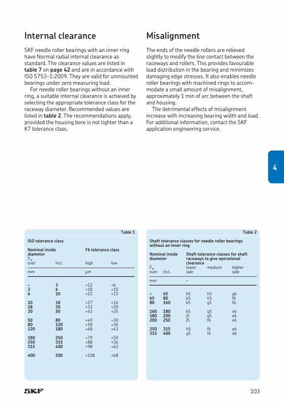
Internal clearanceSKF needle roller bearings with an inner ring have Normal radial internal clearance as standard. The clearance values are listed in table 7 on page 42 and are in accordance with ISO 5753-1:2009. They are valid for unmounted bearings under zero measuring load.
For needle roller bearings without an inner ring, a suitable internal clearance is achieved by selecting the appropriate tolerance class for the raceway diameter. Recommended values are listed in table 2. The recommendations apply, pro vided the housing bore is not tighter than a K7 tolerance class.
Table 2
Shaft tolerance classes for needle roller bearings without an inner ring
Nominal inside Shaft tolerance classes for shaft diameter raceways to give operational clearanceFw lower medium higherover incl. side side
mm –
– 65 k5 h5 g665 80 k5 h5 f680 160 k5 g5 f6
160 180 k5 g5 e6180 200 j5 g5 e6200 250 j5 f6 e6
250 315 h5 f6 e6315 400 g5 f6 d6
Table 1
ISO tolerance class
Nominal inside F6 tolerance classdiameterFw over incl. high low
mm μm
– 3 +12 +63 6 +18 +106 10 +22 +13
10 18 +27 +1618 30 +33 +2030 50 +41 +25
50 80 +49 +3080 120 +58 +36120 180 +68 +43
180 250 +79 +50250 315 +88 +56315 400 +98 +62
400 500 +108 +68
MisalignmentThe ends of the needle rollers are relieved slightly to modify the line contact between the raceways and rollers. This provides favourable load distribution in the bearing and minimizes damaging edge stresses. It also enables needle roller bearings with machined rings to accom-modate a small amount of misalignment, approximately 1 min of arc between the shaft and housing.
The detrimental effects of misalignment increase with increasing bearing width and load. For additional information, contact the SKF application engineering service.
103
4
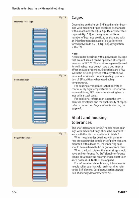
Needle roller bearings with machined rings
CagesDepending on their size, SKF needle roller bear-ings with machined rings are fitted as standard with a machined steel († fig. 15) or sheet steel cage († fig. 16), no designation suffix. A number of bearings are fitted as standard with aninjectionmouldedcageofglassfibrerein-forced polyamide 66 († fig. 17), designation suffix TN.
Note Needle roller bearings with a polyamide 66 cage that are not sealed can be operated at tempera-tures up to 120 °C. The lubricants generally used for rolling bearings do not have a detrimental effect on cage properties. Exceptions are a few synthetic oils and greases with a synthetic oil base and lubricants containing a high propor-tion of EP additives when used at high temperatures.
For bearing arrangements that operate at continuously high temperatures or under ardu-ous conditions, SKF recommends using bear-ings with a steel cage.
For additional information about the tem-pera ture resistance and the applicability of cages, refer to the section Cage materials, starting on page 44.
Shaft and housing tolerancesThe shaft tolerances for SKF needle roller bear-ings with machined rings should be in accord-ance with the fits that are listed in table 3.
When needle roller bearings with an inner ring are used under conditions of point load and mounted with a loose fit, the inner ring seat should be machined to h6 or g6 tolerance class.
When the load rotates, the inner rings should have an interference fit. Sufficient interference can be obtained if the recommended shaft toler-ance classes († table 3) are applied.
For information about housing tolerances for needle roller bearings with an inner ring, refer to the SKF General Catalogue, section Application of bearings/Recommended fits.
Fig. 15
Machined steel cage
Fig. 16
Sheet steel cage
Fig. 17
Polyamide 66 cage
104
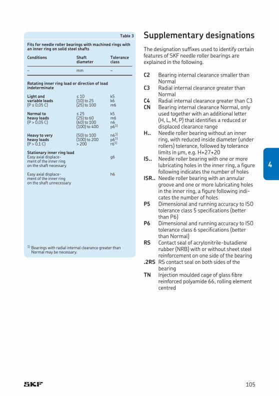
Table 3
Fits for needle roller bearings with machined rings with an inner ring on solid steel shafts
Conditions Shaft Tolerance diameter class
– mm –
Rotating inner ring load or direction of load indeterminate
Light and ≤ 10 k5variable loads (10) to 25 k6(P ≤ 0,05 C) (25) to 100 m6
Normal to ≤ 25 k5heavy loads (25) to 60 m6(P > 0,05 C) (60) to 100 n6 (100) to 400 p61)
Heavy to very (50) to 100 n61)
heavy loads (100) to 200 p61)
(P > 0,1 C) > 200 r61)
Stationary inner ring loadEasy axial displace- g6 ment of the inner ring on the shaft necessary
Easy axial displace- h6 ment of the inner ring on the shaft unnecessary
Supplementary designationsThe designation suffixes used to identify certain features of SKF needle roller bearings are explained in the following.
C2 Bearing internal clearance smaller than Normal
C3 Radial internal clearance greater than Normal
C4 Radial internal clearance greater than C3CN Bearing internal clearance Normal, only
used together with an additional letter (H,L,M,P)thatidentifiesareducedordisplaced clearance range
H.. Needle roller bearing without an inner ring, with reduced inside diameter (under rollers) tolerance, followed by tolerance limits in μm, e.g. H+27+20
IS.. Needle roller bearing with one or more lubricating holes in the inner ring, a figure following indicates the number of holes
ISR.. Needle roller bearing with an annular groove and one or more lubricating holes in the inner ring, a figure following indi-cates the number of holes
P5 Dimensional and running accuracy to ISO tolerance class 5 specifications (better than P6)
P6 Dimensional and running accuracy to ISO tolerance class 6 specifications (better than Normal)
RS Contact seal of acrylonitrile-butadiene rubber (NRB) with or without sheet steel reinforcement on one side of the bearing
.2RS RS contact seal on both sides of the bearing
TN Injectionmouldedcageofglassfibrere inforced polyamide 66, rolling element centred
1) Bearings with radial internal clearance greater than Normal may be necessary.
105
4
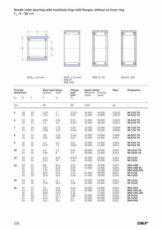
5 10 10 2,29 2 0,212 36 000 40 000 0,0031 NK 5/10 TN 10 12 2,92 2,7 0,29 36 000 40 000 0,0037 NK 5/12 TN 6 12 10 2,55 2,36 0,25 34 000 38 000 0,0047 NK 6/10 TN 12 12 3,3 3,2 0,345 34 000 38 000 0,0057 NK 6/12 TN 7 14 10 2,81 2,75 0,29 32 000 36 000 0,0069 NK 7/10 TN 14 12 3,58 3,75 0,415 32 000 36 000 0,0082 NK 7/12 TN 8 15 12 3,8 4,25 0,465 32 000 36 000 0,0087 NK 8/12 TN 15 16 5,01 5,85 0,67 32 000 36 000 0,012 NK 8/16 TN 9 16 12 4,4 5,2 0,57 30 000 34 000 0,010 NK 9/12 TN 16 16 5,72 7,2 0,815 30 000 34 000 0,013 NK 9/16 TN 10 17 12 4,4 5,4 0,62 28 000 32 000 0,010 NK 10/12 TN 17 16 5,94 8 0,9 28 000 32 000 0,013 NK 10/16 TN 12 19 12 6,71 8,15 0,965 26 000 30 000 0,012 NK 12/12 19 16 9,13 12 1,46 26 000 30 000 0,016 NK 12/16 14 22 13 8,8 10,4 1,25 26 000 30 000 0,017 RNA 4900 22 13 7,37 8,15 0,95 13 000 12 000 0,016 RNA 4900 RS 22 13 7,37 8,15 0,95 – 12 000 0,016 RNA 4900.2RS 22 16 10,2 12,5 1,53 24 000 28 000 0,021 NK 14/16 22 20 12,8 16,6 2,08 24 000 28 000 0,026 NK 14/20 15 23 16 11 14 1,7 24 000 26 000 0,022 NK 15/16 23 20 13,8 18,3 2,28 24 000 26 000 0,027 NK 15/20 16 24 13 9,9 12,2 1,46 22 000 26 000 0,017 RNA 4901 24 13 8,09 9,65 1,14 22 000 11 000 0,018 RNA 4901 RS 24 13 8,09 9,65 1,14 – 11 000 0,018 RNA 4901.2RS 24 16 11,7 15,3 1,86 22 000 26 000 0,022 NK 16/16 24 20 14,5 20 2,5 22 000 26 000 0,028 NK 16/20 24 22 16,1 23,2 2,9 22 000 26 000 0,031 RNA 6901
Needle roller bearings with machined rings with flanges, without an inner ringFw 5 – 16 mm
Principal Basic load ratings Fatigue Speed ratings Mass Designationdimensions dynamic static load Reference Limiting limit speed speed Fw D C C C0 Pu
mm kN kN r/min kg –
C
Fw
r1r2
D
RNA 49.. RS RNA 49...2RS NK (Fw ≤ 10 mm) NK (Fw ≥ 12 mm)RNA 49RNA 6901
106

5 0,15 8,8 0,1 G 5¥10¥2 S 0,15 8,8 0,1 G 5¥10¥2 S 6 0,15 10,8 0,1 G 6¥12¥2 S 0,15 10,8 0,1 G 6¥12¥2 S 7 0,3 12 0,3 G 7¥14¥2 0,3 12 0,3 G 7¥14¥2 8 0,3 13 0,3 G/SD 8¥15¥3 0,3 13 0,3 G/SD 8¥15¥3 9 0,3 14 0,3 G 9¥16¥3 0,3 14 0,3 G 9¥16¥3 10 0,3 15 0,3 G/SD 10¥17¥3 0,3 15 0,3 G/SD 10¥17¥3 12 0,3 17 0,3 G/SD 12¥19¥3 0,3 17 0,3 G/SD 12¥19¥3 14 0,3 20 0,3 G/SD 14¥22¥3 0,3 20 0,3 – 0,3 20 0,3 – 0,3 20 0,3 G/SD 14¥22¥3 0,3 20 0,3 G/SD 14¥22¥3 15 0,3 21 0,3 G/SD 15¥23¥3 0,3 21 0,3 G/SD 15¥23¥3 16 0,3 22 0,3 G/SD 16¥24¥3 0,3 22 0,3 – 0,3 22 0,3 – 0,3 22 0,3 G/SD 16¥24¥3 0,3 22 0,3 G/SD 16¥24¥3 0,3 22 0,3 G/SD 16¥24¥3
Dimensions Abutment and Appropriate seal1)
fillet dimensions Designation Fw r1,2 Da ra min max max
mm mm –
Da
ra
1) For additional information, refer to the section Radial shaft seals with a low cross sectional height, starting on page 208. For additional information about SKF seals, refer to the SKF catalogue Industrial shaft seals.
107
4.1
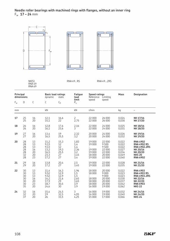
17 25 16 12,1 16,6 2 22 000 26 000 0,024 NK 17/16 25 20 15,1 22 2,75 22 000 26 000 0,030 NK 17/20 18 26 16 12,8 17,6 2,16 22 000 24 000 0,025 NK 18/16 26 20 16,1 23,6 3 22 000 24 000 0,031 NK 18/20 19 27 16 13,4 19 2,32 20 000 24 000 0,026 NK 19/16 27 20 16,5 25,5 3,2 20 000 24 000 0,032 NK 19/20 20 28 13 11,2 15,3 1,83 19 000 22 000 0,022 RNA 4902 28 13 9,13 12 1,4 19 000 9 500 0,022 RNA 4902 RS 28 13 9,13 12 1,4 – 9 500 0,022 RNA 4902.2RS 28 16 13,2 19,3 2,36 19 000 22 000 0,027 NK 20/16 28 20 16,5 25,5 3,2 19 000 22 000 0,034 NK 20/20 32 20 23,3 27 3,45 18 000 20 000 0,049 NKS 20 28 23 17,2 27 3,4 19 000 22 000 0,040 RNA 6902 21 29 16 13,8 20,4 2,5 19 000 22 000 0,028 NK 21/16 29 20 17,2 27 3,45 19 000 22 000 0,035 NK 21/20 22 30 13 11,4 16,3 1,96 18 000 20 000 0,022 RNA 4903 30 13 9,52 12,9 1,5 18 000 9 000 0,023 RNA 4903 RS 30 13 9,52 12,9 1,5 – 9 000 0,023 RNA 4903.2RS 30 16 14,2 21,6 2,65 18 000 20 000 0,030 NK 22/16 30 20 17,9 29 3,65 18 000 20 000 0,037 NK 22/20 30 23 18,7 30,5 3,9 18 000 20 000 0,042 RNA 6903 35 20 24,6 30 3,9 16 000 19 000 0,062 NKS 22 24 32 16 15,4 24,5 3 16 000 19 000 0,032 NK 24/16 32 20 19 32,5 4,05 16 000 19 000 0,040 NK 24/20 37 20 26 33,5 4,25 15 000 17 000 0,066 NKS 24
Principal Basic load ratings Fatigue Speed ratings Mass Designationdimensions dynamic static load Reference Limiting limit speed speed Fw D C C C0 Pu
mm kN kN r/min kg –
Needle roller bearings with machined rings with flanges, without an inner ringFw 17 – 24 mm
Fw
C
D
r2r1
RNA 49.. RS RNA 49...2RSNK(S)RNA 49RNA 69
108
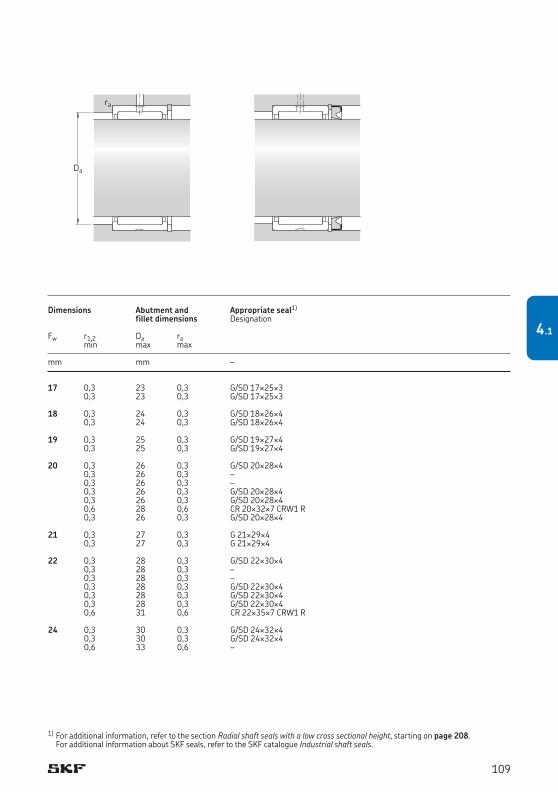
17 0,3 23 0,3 G/SD 17¥25¥3 0,3 23 0,3 G/SD 17¥25¥3 18 0,3 24 0,3 G/SD 18¥26¥4 0,3 24 0,3 G/SD 18¥26¥4 19 0,3 25 0,3 G/SD 19¥27¥4 0,3 25 0,3 G/SD 19¥27¥4 20 0,3 26 0,3 G/SD 20¥28¥4 0,3 26 0,3 – 0,3 26 0,3 – 0,3 26 0,3 G/SD 20¥28¥4 0,3 26 0,3 G/SD 20¥28¥4 0,6 28 0,6 CR 20¥32¥7 CRW1 R 0,3 26 0,3 G/SD 20¥28¥4 21 0,3 27 0,3 G 21¥29¥4 0,3 27 0,3 G 21¥29¥4 22 0,3 28 0,3 G/SD 22¥30¥4 0,3 28 0,3 – 0,3 28 0,3 – 0,3 28 0,3 G/SD 22¥30¥4 0,3 28 0,3 G/SD 22¥30¥4 0,3 28 0,3 G/SD 22¥30¥4 0,6 31 0,6 CR 22¥35¥7 CRW1 R 24 0,3 30 0,3 G/SD 24¥32¥4 0,3 30 0,3 G/SD 24¥32¥4 0,6 33 0,6 –
Dimensions Abutment and Appropriate seal1)
fillet dimensions Designation Fw r1,2 Da ra min max max
mm mm –
1) For additional information, refer to the section Radial shaft seals with a low cross sectional height, starting on page 208. For additional information about SKF seals, refer to the SKF catalogue Industrial shaft seals.
Da
ra
109
4.1
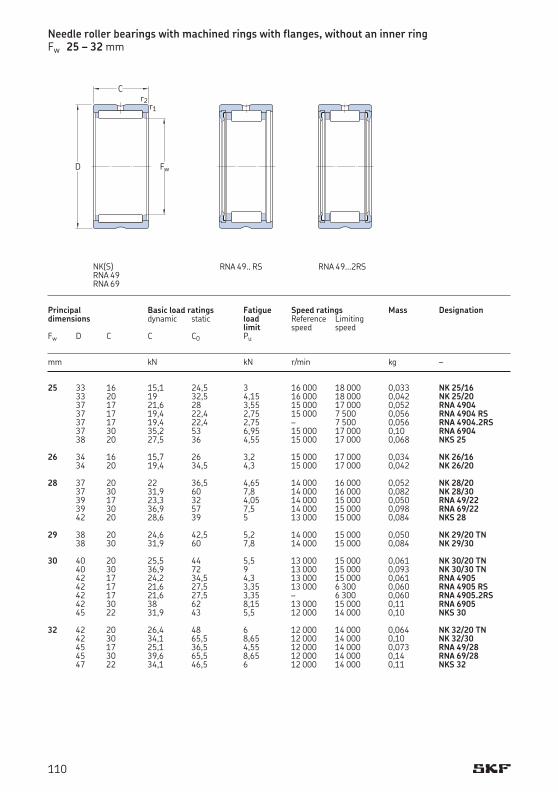
25 33 16 15,1 24,5 3 16 000 18 000 0,033 NK 25/16 33 20 19 32,5 4,15 16 000 18 000 0,042 NK 25/20 37 17 21,6 28 3,55 15 000 17 000 0,052 RNA 4904 37 17 19,4 22,4 2,75 15 000 7 500 0,056 RNA 4904 RS 37 17 19,4 22,4 2,75 – 7 500 0,056 RNA 4904.2RS 37 30 35,2 53 6,95 15 000 17 000 0,10 RNA 6904 38 20 27,5 36 4,55 15 000 17 000 0,068 NKS 25 26 34 16 15,7 26 3,2 15 000 17 000 0,034 NK 26/16 34 20 19,4 34,5 4,3 15 000 17 000 0,042 NK 26/20 28 37 20 22 36,5 4,65 14 000 16 000 0,052 NK 28/20 37 30 31,9 60 7,8 14 000 16 000 0,082 NK 28/30 39 17 23,3 32 4,05 14 000 15 000 0,050 RNA 49/22 39 30 36,9 57 7,5 14 000 15 000 0,098 RNA 69/22 42 20 28,6 39 5 13 000 15 000 0,084 NKS 28 29 38 20 24,6 42,5 5,2 14 000 15 000 0,050 NK 29/20 TN 38 30 31,9 60 7,8 14 000 15 000 0,084 NK 29/30 30 40 20 25,5 44 5,5 13 000 15 000 0,061 NK 30/20 TN 40 30 36,9 72 9 13 000 15 000 0,093 NK 30/30 TN 42 17 24,2 34,5 4,3 13 000 15 000 0,061 RNA 4905 42 17 21,6 27,5 3,35 13 000 6 300 0,060 RNA 4905 RS 42 17 21,6 27,5 3,35 – 6 300 0,060 RNA 4905.2RS 42 30 38 62 8,15 13 000 15 000 0,11 RNA 6905 45 22 31,9 43 5,5 12 000 14 000 0,10 NKS 30 32 42 20 26,4 48 6 12 000 14 000 0,064 NK 32/20 TN 42 30 34,1 65,5 8,65 12 000 14 000 0,10 NK 32/30 45 17 25,1 36,5 4,55 12 000 14 000 0,073 RNA 49/28 45 30 39,6 65,5 8,65 12 000 14 000 0,14 RNA 69/28 47 22 34,1 46,5 6 12 000 14 000 0,11 NKS 32
Principal Basic load ratings Fatigue Speed ratings Mass Designationdimensions dynamic static load Reference Limiting limit speed speed Fw D C C C0 Pu
mm kN kN r/min kg –
Needle roller bearings with machined rings with flanges, without an inner ringFw 25 – 32 mm
Fw
C
D
r2r1
RNA 49.. RS RNA 49...2RSNK(S)RNA 49RNA 69
110

25 0,3 31 0,3 G/SD 25¥33¥4 0,3 31 0,3 G/SD 25¥33¥4 0,3 35 0,3 CR 25¥35¥7 CRW1 R 0,3 35 0,3 – 0,3 35 0,3 – 0,3 35 0,3 CR 25¥35¥7 CRW1 R 0,6 34 0,6 CR 25¥38¥7 CRW1 R 26 0,3 32 0,3 G/SD 26¥34¥4 0,3 32 0,3 G/SD 26¥34¥4 28 0,3 35 0,3 G 28¥37¥4 0,3 35 0,3 G 28¥37¥4 0,3 37 0,3 – 0,3 37 0,3 – 0,6 38 0,6 CR 28¥42¥7 CRW1 R 29 0,3 36 0,3 G 29¥38¥4 0,3 36 0,3 G 29¥38¥4 30 0,3 38 0,3 G/SD 30¥40¥4 0,3 38 0,3 G/SD 30¥40¥4 0,3 40 0,3 CR 30¥42¥7 CRW1 R 0,3 40 0,3 – 0,3 40 0,3 – 0,3 40 0,3 CR 30¥42¥7 CRW1 R 0,6 41 0,6 CR 30¥45¥8 CRW1 R 32 0,3 40 0,3 G/SD 32¥42¥4 0,3 40 0,3 G/SD 32¥42¥4 0,3 43 0,3 G 32¥45¥4 0,3 43 0,3 G 32¥45¥4 0,6 43 0,6 CR 32¥47¥8 CRW1 R
Dimensions Abutment and Appropriate seal1)
fillet dimensions Designation Fw r1,2 Da ra min max max
mm mm –
1) For additional information, refer to the section Radial shaft seals with a low cross sectional height, starting on page 208. For additional information about SKF seals, refer to the SKF catalogue Industrial shaft seals.
Da
ra
111
4.1
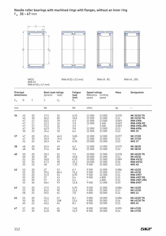
35 45 20 27,5 52 6,55 11 000 13 000 0,070 NK 35/20 TN 45 30 40,2 85 10,6 11 000 13 000 0,11 NK 35/30 TN 47 17 25,5 39 4,9 11 000 13 000 0,069 RNA 4906 47 17 23,3 32 3,9 11 000 5 600 0,069 RNA 4906 RS 47 17 23,3 32 3,9 – 5 600 0,069 RNA 4906.2RS 47 30 42,9 75 9,8 11 000 13 000 0,13 RNA 6906 50 22 35,2 50 6,4 11 000 12 000 0,12 NKS 35 37 47 20 25,1 46,5 5,85 11 000 12 000 0,077 NK 37/20 47 30 36,9 76,5 10 11 000 12 000 0,11 NK 37/30 52 22 36,9 54 6,95 10 000 12 000 0,12 NKS 37 38 48 20 25,5 49 6,2 11 000 12 000 0,079 NK 38/20 48 30 37,4 80 10,4 11 000 12 000 0,12 NK 38/30 40 50 20 30,3 61 7,5 10 000 11 000 0,078 NK 40/20 TN 50 30 38 83 10,8 10 000 11 000 0,13 NK 40/30 52 20 30,8 51 6,55 10 000 11 000 0,089 RNA 49/32 52 36 47,3 90 11,2 10 000 11 000 0,16 RNA 69/32 55 22 38 57 7,35 9 500 11 000 0,13 NKS 40 42 52 20 27 53 6,7 9 500 11 000 0,086 NK 42/20 52 30 39,1 86,5 11,2 9 500 11 000 0,13 NK 42/30 55 20 31,9 54 6,95 9 500 11 000 0,11 RNA 4907 55 20 27 43 5,4 9 500 4 800 0,11 RNA 4907 RS 55 20 27 43 5,4 – 4 800 0,11 RNA 4907.2RS 55 36 48,4 93 11,8 9 500 11 000 0,19 RNA 6907 43 53 20 27,5 55 6,95 9 500 11 000 0,086 NK 43/20 53 30 40,2 90 11,6 9 500 11 000 0,13 NK 43/30 58 22 39,1 61 7,8 9 000 10 000 0,14 NKS 43 45 55 20 31,4 67 8,3 9 000 10 000 0,086 NK 45/20 TN 55 30 45,7 108 13,4 9 000 10 000 0,14 NK 45/30 TN 60 22 40,2 64 8,3 8 500 10 000 0,15 NKS 45 47 57 20 29,2 61 7,65 8 500 10 000 0,095 NK 47/20 57 30 41,8 98 12,9 8 500 10 000 0,14 NK 47/30
Principal Basic load ratings Fatigue Speed ratings Mass Designationdimensions dynamic static load Reference Limiting limit speed speed Fw D C C C0 Pu
mm kN kN r/min kg –
Needle roller bearings with machined rings with flanges, without an inner ringFw 35 – 47 mm
Fw
C
D
r2r1
RNA 69 (D ≥ 52 mm) RNA 49.. RS RNA 49...2RS NK(S)RNA 49RNA 69 (D ≤ 47 mm)
112
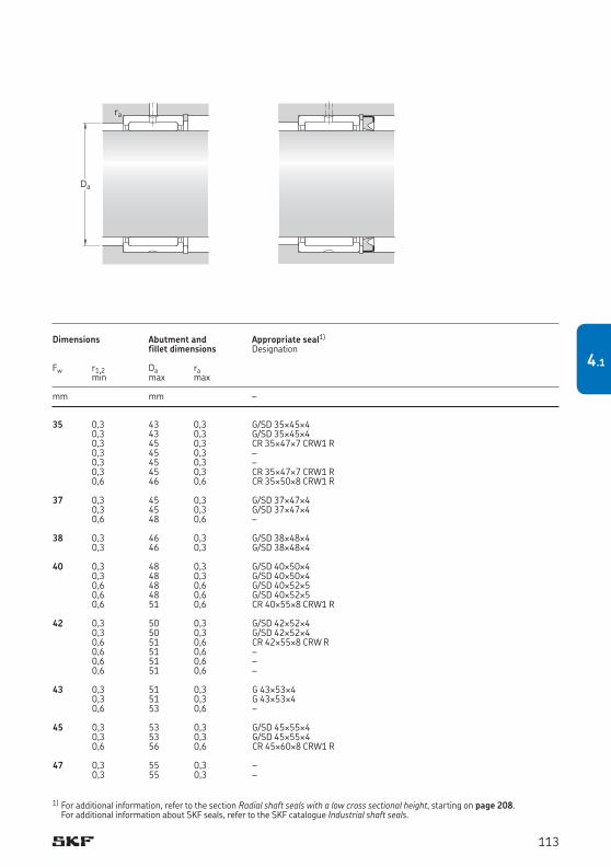
35 0,3 43 0,3 G/SD 35¥45¥4 0,3 43 0,3 G/SD 35¥45¥4 0,3 45 0,3 CR 35¥47¥7 CRW1 R 0,3 45 0,3 – 0,3 45 0,3 – 0,3 45 0,3 CR 35¥47¥7 CRW1 R 0,6 46 0,6 CR 35¥50¥8 CRW1 R 37 0,3 45 0,3 G/SD 37¥47¥4 0,3 45 0,3 G/SD 37¥47¥4 0,6 48 0,6 – 38 0,3 46 0,3 G/SD 38¥48¥4 0,3 46 0,3 G/SD 38¥48¥4 40 0,3 48 0,3 G/SD 40¥50¥4 0,3 48 0,3 G/SD 40¥50¥4 0,6 48 0,6 G/SD 40¥52¥5 0,6 48 0,6 G/SD 40¥52¥5 0,6 51 0,6 CR 40¥55¥8 CRW1 R 42 0,3 50 0,3 G/SD 42¥52¥4 0,3 50 0,3 G/SD 42¥52¥4 0,6 51 0,6 CR 42¥55¥8 CRW R 0,6 51 0,6 – 0,6 51 0,6 – 0,6 51 0,6 – 43 0,3 51 0,3 G 43¥53¥4 0,3 51 0,3 G 43¥53¥4 0,6 53 0,6 – 45 0,3 53 0,3 G/SD 45¥55¥4 0,3 53 0,3 G/SD 45¥55¥4 0,6 56 0,6 CR 45¥60¥8 CRW1 R 47 0,3 55 0,3 – 0,3 55 0,3 –
Dimensions Abutment and Appropriate seal1)
fillet dimensions Designation Fw r1,2 Da ra min max max
mm mm –
1) For additional information, refer to the section Radial shaft seals with a low cross sectional height, starting on page 208. For additional information about SKF seals, refer to the SKF catalogue Industrial shaft seals.
Da
ra
113
4.1
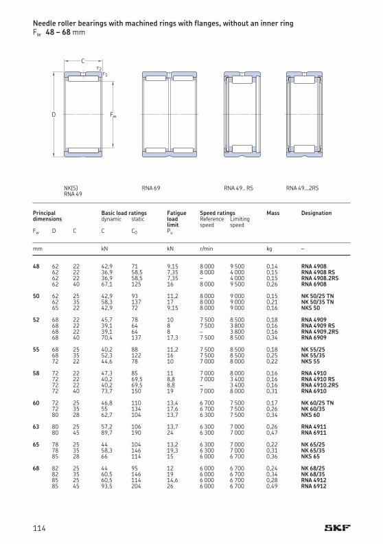
48 62 22 42,9 71 9,15 8 000 9 500 0,14 RNA 4908 62 22 36,9 58,5 7,35 8 000 4 000 0,15 RNA 4908 RS 62 22 36,9 58,5 7,35 – 4 000 0,15 RNA 4908.2RS 62 40 67,1 125 16 8 000 9 500 0,26 RNA 6908 50 62 25 42,9 93 11,2 8 000 9 000 0,15 NK 50/25 TN 62 35 58,3 137 17 8 000 9 000 0,21 NK 50/35 TN 65 22 42,9 72 9,15 8 000 9 000 0,16 NKS 50 52 68 22 45,7 78 10 7 500 8 500 0,18 RNA 4909 68 22 39,1 64 8 7 500 3 800 0,16 RNA 4909 RS 68 22 39,1 64 8 – 3 800 0,16 RNA 4909.2RS 68 40 70,4 137 17,3 7 500 8 500 0,34 RNA 6909 55 68 25 40,2 88 11,2 7 500 8 500 0,18 NK 55/25 68 35 52,3 122 16 7 500 8 500 0,25 NK 55/35 72 22 44,6 78 10 7 000 8 000 0,22 NKS 55 58 72 22 47,3 85 11 7 000 8 000 0,16 RNA 4910 72 22 40,2 69,5 8,8 7 000 3 400 0,16 RNA 4910 RS 72 22 40,2 69,5 8,8 – 3 400 0,16 RNA 4910.2RS 72 40 73,7 150 19 7 000 8 000 0,31 RNA 6910 60 72 25 46,8 110 13,4 6 700 7 500 0,17 NK 60/25 TN 72 35 55 134 17,6 6 700 7 500 0,26 NK 60/35 80 28 62,7 104 13,7 6 300 7 500 0,34 NKS 60 63 80 25 57,2 106 13,7 6 300 7 000 0,26 RNA 4911 80 45 89,7 190 24 6 300 7 000 0,47 RNA 6911 65 78 25 44 104 13,2 6 300 7 000 0,22 NK 65/25 78 35 58,3 146 19,3 6 300 7 000 0,31 NK 65/35 85 28 66 114 15 6 000 6 700 0,36 NKS 65 68 82 25 44 95 12 6 000 6 700 0,24 NK 68/25 82 35 60,5 146 19 6 000 6 700 0,34 NK 68/35 85 25 60,5 114 14,6 6 000 6 700 0,28 RNA 4912 85 45 93,5 204 26 6 000 6 700 0,49 RNA 6912
Principal Basic load ratings Fatigue Speed ratings Mass Designationdimensions dynamic static load Reference Limiting limit speed speed Fw D C C C0 Pu
mm kN kN r/min kg –
Needle roller bearings with machined rings with flanges, without an inner ringFw 48 – 68 mm
NK(S)RNA 49
RNA 69 RNA 49.. RS RNA 49...2RS
Fw
C
D
r2r1
114

48 0,6 58 0,6 CR 48¥62¥8 CRW1 R 0,6 58 0,6 – 0,6 58 0,6 – 0,6 58 0,6 – 50 0,6 58 0,6 G/SD 50¥62¥5 0,6 58 0,6 G/SD 50¥62¥5 1 60 1 CR 50¥65¥8 CRW1 R 52 0,6 64 0,6 CR 52¥68¥8 CRW1 R 0,6 64 0,6 – 0,6 64 0,6 – 0,6 64 0,6 – 55 0,6 64 0,6 – 0,6 64 0,6 – 1 67 1 CR 55¥72¥8 CRW1 R 58 0,6 68 0,6 CR 58¥72¥8 CRW1 R 0,6 68 0,6 – 0,6 68 0,6 – 0,6 68 0,6 – 60 0,6 68 0,6 – 0,6 68 0,6 – 1,1 73,5 1 – 63 1 75 1 CR 63¥80¥8 CRW1 R 1 75 1 – 65 0,6 74 0,6 – 0,6 74 0,6 – 1,1 78,5 1 CR 65¥85¥8 CRW1 R 68 0,6 78 0,6 – 0,6 78 0,6 – 1 80 1 CR 68¥85¥8 CRW1 R 1 80 1 –
Dimensions Abutment and Appropriate seal1)
fillet dimensions Designation Fw r1,2 Da ra min max max
mm mm –
1) For additional information, refer to the section Radial shaft seals with a low cross sectional height, starting on page 208. For additional information about SKF seals, refer to the SKF catalogue Industrial shaft seals.
Da
ra
115
4.1
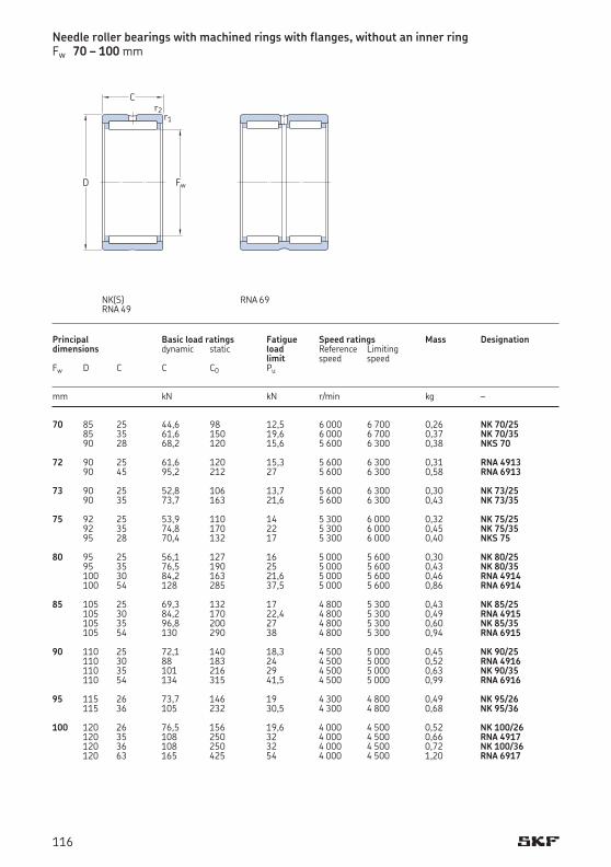
70 85 25 44,6 98 12,5 6 000 6 700 0,26 NK 70/25 85 35 61,6 150 19,6 6 000 6 700 0,37 NK 70/35 90 28 68,2 120 15,6 5 600 6 300 0,38 NKS 70 72 90 25 61,6 120 15,3 5 600 6 300 0,31 RNA 4913 90 45 95,2 212 27 5 600 6 300 0,58 RNA 6913 73 90 25 52,8 106 13,7 5 600 6 300 0,30 NK 73/25 90 35 73,7 163 21,6 5 600 6 300 0,43 NK 73/35 75 92 25 53,9 110 14 5 300 6 000 0,32 NK 75/25 92 35 74,8 170 22 5 300 6 000 0,45 NK 75/35 95 28 70,4 132 17 5 300 6 000 0,40 NKS 75 80 95 25 56,1 127 16 5 000 5 600 0,30 NK 80/25 95 35 76,5 190 25 5 000 5 600 0,43 NK 80/35 100 30 84,2 163 21,6 5 000 5 600 0,46 RNA 4914 100 54 128 285 37,5 5 000 5 600 0,86 RNA 6914 85 105 25 69,3 132 17 4 800 5 300 0,43 NK 85/25 105 30 84,2 170 22,4 4 800 5 300 0,49 RNA 4915 105 35 96,8 200 27 4 800 5 300 0,60 NK 85/35 105 54 130 290 38 4 800 5 300 0,94 RNA 6915 90 110 25 72,1 140 18,3 4 500 5 000 0,45 NK 90/25 110 30 88 183 24 4 500 5 000 0,52 RNA 4916 110 35 101 216 29 4 500 5 000 0,63 NK 90/35 110 54 134 315 41,5 4 500 5 000 0,99 RNA 6916 95 115 26 73,7 146 19 4 300 4 800 0,49 NK 95/26 115 36 105 232 30,5 4 300 4 800 0,68 NK 95/36 100 120 26 76,5 156 19,6 4 000 4 500 0,52 NK 100/26 120 35 108 250 32 4 000 4 500 0,66 RNA 4917 120 36 108 250 32 4 000 4 500 0,72 NK 100/36 120 63 165 425 54 4 000 4 500 1,20 RNA 6917
Principal Basic load ratings Fatigue Speed ratings Mass Designationdimensions dynamic static load Reference Limiting limit speed speed Fw D C C C0 Pu
mm kN kN r/min kg –
Needle roller bearings with machined rings with flanges, without an inner ringFw 70 – 100 mm
NK(S)RNA 49
Fw
C
D
r2r1
RNA 69
116
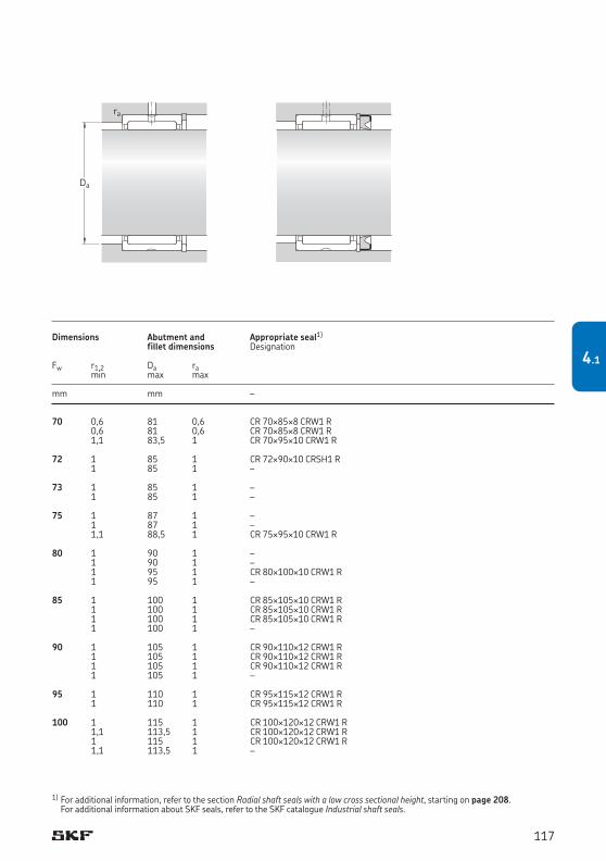
70 0,6 81 0,6 CR 70¥85¥8 CRW1 R 0,6 81 0,6 CR 70¥85¥8 CRW1 R 1,1 83,5 1 CR 70¥95¥10 CRW1 R 72 1 85 1 CR 72¥90¥10CRSH1R 1 85 1 – 73 1 85 1 – 1 85 1 – 75 1 87 1 – 1 87 1 – 1,1 88,5 1 CR 75¥95¥10 CRW1 R 80 1 90 1 – 1 90 1 – 1 95 1 CR 80¥100¥10 CRW1 R 1 95 1 – 85 1 100 1 CR 85¥105¥10 CRW1 R 1 100 1 CR 85¥105¥10 CRW1 R 1 100 1 CR 85¥105¥10 CRW1 R 1 100 1 – 90 1 105 1 CR 90¥110¥12 CRW1 R 1 105 1 CR 90¥110¥12 CRW1 R 1 105 1 CR 90¥110¥12 CRW1 R 1 105 1 – 95 1 110 1 CR 95¥115¥12 CRW1 R 1 110 1 CR 95¥115¥12 CRW1 R 100 1 115 1 CR 100¥120¥12 CRW1 R 1,1 113,5 1 CR 100¥120¥12 CRW1 R 1 115 1 CR 100¥120¥12 CRW1 R 1,1 113,5 1 –
Dimensions Abutment and Appropriate seal1)
fillet dimensions Designation
Fw r1,2 Da ra min max max
mm mm –
1) For additional information, refer to the section Radial shaft seals with a low cross sectional height, starting on page 208. For additional information about SKF seals, refer to the SKF catalogue Industrial shaft seals.
Da
ra
117
4.1
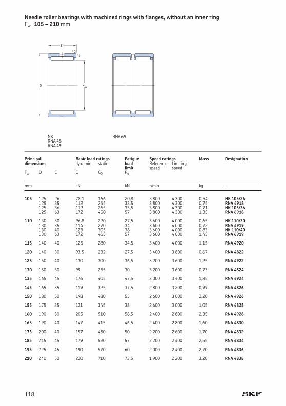
105 125 26 78,1 166 20,8 3 800 4 300 0,54 NK 105/26 125 35 112 265 33,5 3 800 4 300 0,75 RNA 4918 125 36 112 265 33,5 3 800 4 300 0,71 NK 105/36 125 63 172 450 57 3 800 4 300 1,35 RNA 6918 110 130 30 96,8 220 27,5 3 600 4 000 0,65 NK 110/30 130 35 114 270 34 3 600 4 000 0,72 RNA 4919 130 40 123 305 38 3 600 4 000 0,83 NK 110/40 130 63 172 465 57 3 600 4 000 1,45 RNA 6919 115 140 40 125 280 34,5 3 400 4 000 1,15 RNA 4920 120 140 30 93,5 232 27,5 3 400 3 800 0,67 RNA 4822 125 150 40 130 300 36,5 3 200 3 600 1,25 RNA 4922 130 150 30 99 255 30 3 200 3 600 0,73 RNA 4824 135 165 45 176 405 47,5 3 000 3 400 1,85 RNA 4924 145 165 35 119 325 37,5 2 800 3 200 0,99 RNA 4826 150 180 50 198 480 55 2 600 3 000 2,20 RNA 4926 155 175 35 121 345 38 2 600 3 000 1,05 RNA 4828 160 190 50 205 510 58,5 2 400 2 800 2,35 RNA 4928 165 190 40 147 415 46,5 2 400 2 800 1,60 RNA 4830 175 200 40 157 450 50 2 200 2 600 1,70 RNA 4832 185 215 45 179 520 57 2 200 2 400 2,55 RNA 4834 195 225 45 190 570 60 2 000 2 400 2,70 RNA 4836 210 240 50 220 710 73,5 1 900 2 200 3,20 RNA 4838
Principal Basic load ratings Fatigue Speed ratings Mass Designationdimensions dynamic static load Reference Limiting limit speed speed Fw D C C C0 Pu
mm kN kN r/min kg –
Needle roller bearings with machined rings with flanges, without an inner ringFw 105 – 210 mm
RNA 69NKRNA 48RNA 49
Fw
C
D
r2r1
118
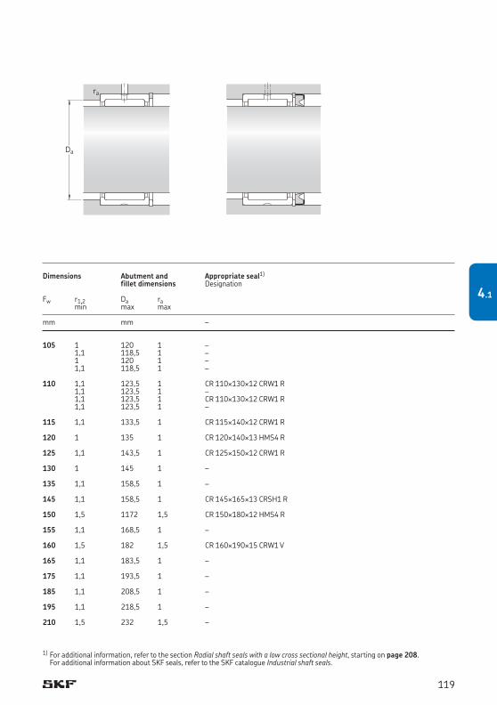
105 1 120 1 – 1,1 118,5 1 – 1 120 1 – 1,1 118,5 1 – 110 1,1 123,5 1 CR 110¥130¥12 CRW1 R 1,1 123,5 1 – 1,1 123,5 1 CR 110¥130¥12 CRW1 R 1,1 123,5 1 – 115 1,1 133,5 1 CR 115¥140¥12 CRW1 R 120 1 135 1 CR 120¥140¥13HMS4R 125 1,1 143,5 1 CR 125¥150¥12 CRW1 R 130 1 145 1 – 135 1,1 158,5 1 – 145 1,1 158,5 1 CR 145¥165¥13CRSH1R 150 1,5 1172 1,5 CR 150¥180¥12HMS4R 155 1,1 168,5 1 – 160 1,5 182 1,5 CR 160¥190¥15 CRW1 V 165 1,1 183,5 1 – 175 1,1 193,5 1 – 185 1,1 208,5 1 – 195 1,1 218,5 1 – 210 1,5 232 1,5 –
Dimensions Abutment and Appropriate seal1)
fillet dimensions Designation Fw r1,2 Da ra min max max
mm mm –
1) For additional information, refer to the section Radial shaft seals with a low cross sectional height, starting on page 208. For additional information about SKF seals, refer to the SKF catalogue Industrial shaft seals.
Da
ra
119
4.1
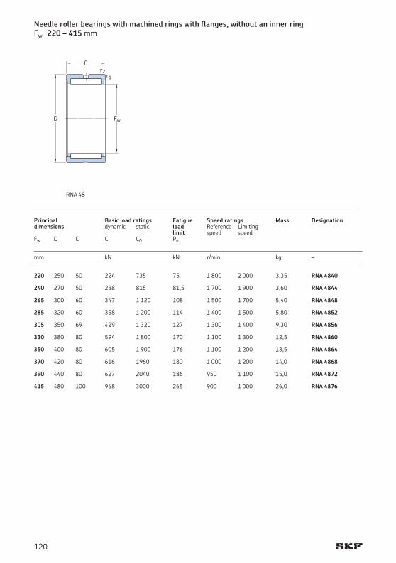
220 250 50 224 735 75 1 800 2 000 3,35 RNA 4840 240 270 50 238 815 81,5 1 700 1 900 3,60 RNA 4844 265 300 60 347 1 120 108 1 500 1 700 5,40 RNA 4848 285 320 60 358 1 200 114 1 400 1 500 5,80 RNA 4852 305 350 69 429 1 320 127 1 300 1 400 9,30 RNA 4856 330 380 80 594 1 800 170 1 100 1 300 12,5 RNA 4860 350 400 80 605 1 900 176 1 100 1 200 13,5 RNA 4864 370 420 80 616 1960 180 1 000 1 200 14,0 RNA 4868 390 440 80 627 2040 186 950 1 100 15,0 RNA 4872 415 480 100 968 3000 265 900 1 000 26,0 RNA 4876
Principal Basic load ratings Fatigue Speed ratings Mass Designationdimensions dynamic static load Reference Limiting limit speed speed Fw D C C C0 Pu
mm kN kN r/min kg –
Needle roller bearings with machined rings with flanges, without an inner ringFw 220 – 415 mm
RNA 48
Fw
C
D
r2r1
120
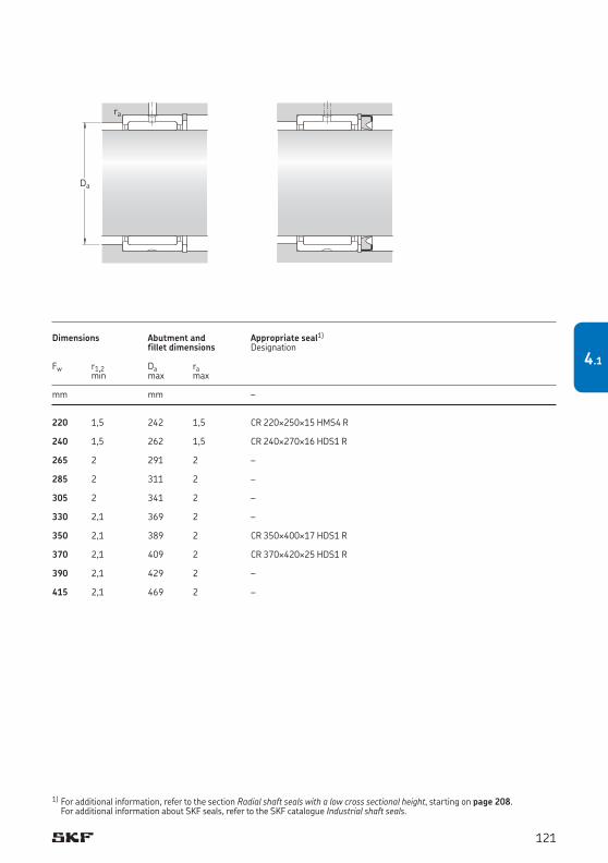
220 1,5 242 1,5 CR 220¥250¥15HMS4R 240 1,5 262 1,5 CR 240¥270¥16HDS1R 265 2 291 2 – 285 2 311 2 – 305 2 341 2 – 330 2,1 369 2 – 350 2,1 389 2 CR 350¥400¥17HDS1R 370 2,1 409 2 CR 370¥420¥25HDS1R 390 2,1 429 2 – 415 2,1 469 2 –
Dimensions Abutment and Appropriate seal1)
fillet dimensions Designation Fw r1,2 Da ra min max max
mm mm –
1) For additional information, refer to the section Radial shaft seals with a low cross sectional height, starting on page 208. For additional information about SKF seals, refer to the SKF catalogue Industrial shaft seals.
Da
ra
121
4.1
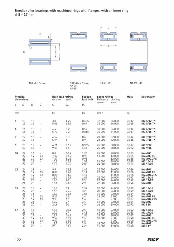
5 15 12 – 3,8 4,25 0,465 32 000 36 000 0,012 NKI 5/12 TN 15 16 – 5,01 5,85 0,67 32 000 36 000 0,015 NKI 5/16 TN 6 16 12 – 4,4 5,2 0,57 30 000 34 000 0,014 NKI 6/12 TN 16 16 – 5,72 7,2 0,815 30 000 34 000 0,017 NKI 6/16 TN 7 17 12 – 4,57 5,7 0,63 28 000 32 000 0,014 NKI 7/12 TN 17 16 – 5,94 8 0,9 28 000 32 000 0,018 NKI 7/16 TN 9 19 12 – 6,71 8,15 0,965 26 000 30 000 0,017 NKI 9/12 19 16 – 9,13 12 1,46 26 000 30 000 0,022 NKI 9/16 10 22 13 – 8,8 10,4 1,25 24 000 28 000 0,023 NA 4900 22 14 13 7,37 8,15 0,95 13 000 12 000 0,025 NA 4900 RS 22 14 13 7,37 8,15 0,95 – 12 000 0,025 NA 4900.2RS 22 16 – 10,2 12,5 1,53 24 000 28 000 0,029 NKI 10/16 22 20 – 12,8 16,6 2,08 24 000 28 000 0,037 NKI 10/20 12 24 13 – 9,9 12,2 1,46 22 000 26 000 0,026 NA 4901 24 14 13 8,09 9,65 1,14 22 000 11 000 0,028 NA 4901 RS 24 14 13 8,09 9,65 1,14 – 11 000 0,028 NA 4901.2RS 24 16 – 11,7 15,3 1,86 22 000 26 000 0,033 NKI 12/16 24 20 – 14,5 20 2,5 22 000 26 000 0,042 NKI 12/20 24 22 – 16,1 23,2 2,9 22 000 26 000 0,046 NA 6901 15 27 16 – 13,4 19 2,32 20 000 24 000 0,039 NKI 15/16 27 20 – 16,5 25,5 3,2 20 000 24 000 0,049 NKI 15/20 28 13 – 11,2 15,3 1,83 19 000 22 000 0,034 NA 4902 28 14 13 9,13 12 1,4 19 000 9 500 0,037 NA 4902 RS 28 14 13 9,13 12 1,4 – 9 500 0,037 NA 4902.2RS 28 23 – 17,2 27 3,4 19 000 22 000 0,064 NA 6902 35 20 – 24,6 30 3,9 16 000 19 000 0,092 NKIS 15 17 29 16 – 13,8 20,4 2,5 19 000 22 000 0,042 NKI 17/16 29 20 – 17,2 27 3,45 19 000 22 000 0,053 NKI 17/20 30 13 – 11,4 16,3 1,96 18 000 20 000 0,037 NA 4903 30 14 13 9,52 12,9 1,5 18 000 9 000 0,040 NA 4903 RS 30 14 13 9,52 12,9 1,5 – 9 000 0,040 NA 4903.2RS 30 23 – 18,7 30,5 3,9 18 000 20 000 0,072 NA 6903 37 20 – 26 33,5 4,25 15 000 17 000 0,098 NKIS 17
Needle roller bearings with machined rings with flanges, with an inner ringd 5 – 17 mm
Principal Basic load ratings Fatigue Speed ratings Mass Designationdimensions dynamic static load limit Reference Limiting speed speedd D B C C C0 Pu
mm kN kN r/min kg –
d
B
r1
F
r1
r2
r2
D
C
B
NA 49.. RS NA 49...2RSNKI (d ≤ 7 mm) NKI(S) (d ≥ 9 mm)NA 49NA 69
122
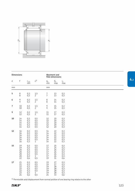
5 8 0,3 1,5 7 13 0,3 8 0,3 2 7 13 0,3 6 9 0,3 1,5 8 14 0,3 9 0,3 2 8 14 0,3 7 10 0,3 1,5 9 15 0,3 10 0,3 2 9 15 0,3 9 12 0,3 1,5 11 17 0,3 12 0,3 2 11 17 0,3 10 14 0,3 0,5 12 20 0,3 14 0,3 0,5 12 20 0,3 14 0,3 0,5 12 20 0,3 14 0,3 0,5 12 20 0,3 14 0,3 0,5 12 20 0,3 12 16 0,3 0,5 14 22 0,3 16 0,3 0,5 14 22 0,3 16 0,3 0,5 14 22 0,3 16 0,3 0,5 14 22 0,3 16 0,3 0,5 14 22 0,3 16 0,3 1 14 22 0,3 15 19 0,3 0,5 17 25 0,3 19 0,3 0,5 17 25 0,3 20 0,3 0,5 17 26 0,3 20 0,3 0,5 17 26 0,3 20 0,3 0,5 17 26 0,3 20 0,3 1 17 26 0,3 22 0,6 0,5 19 31 0,6 17 21 0,3 0,5 19 27 0,3 21 0,3 0,5 19 27 0,3 22 0,3 0,5 19 28 0,3 22 0,3 0,5 19 28 0,3 22 0,3 0,5 19 28 0,3 22 0,3 1 19 28 0,3 24 0,6 0,5 21 33 0,6
Dimensions Abutment and fillet dimensions
d F r1,2 s1) da Da ra min min max max mm mm
1) Permissible axial displacement from normal position of one bearing ring relative to the other
daDa
ra
ra
123
4.2
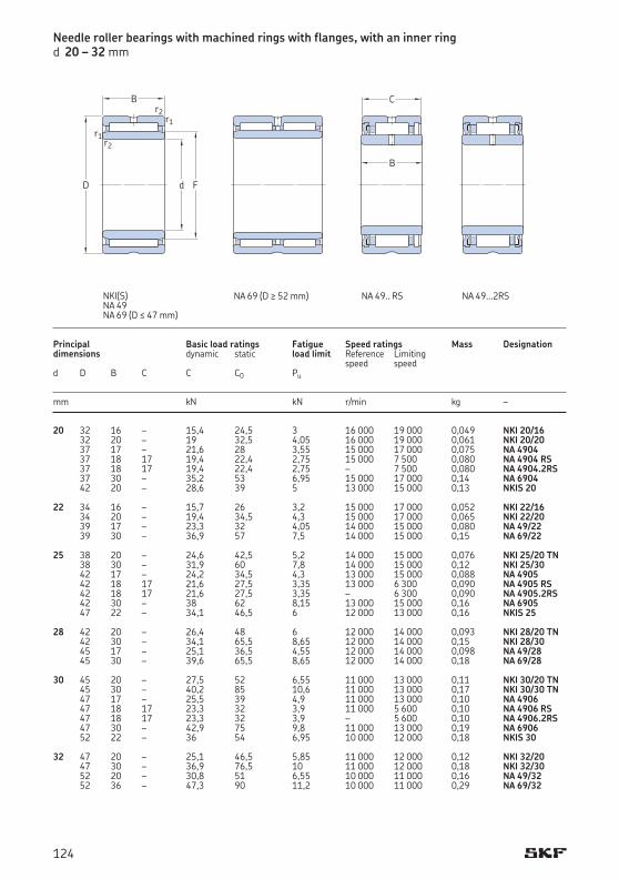
Principal Basic load ratings Fatigue Speed ratings Mass Designationdimensions dynamic static load limit Reference Limiting speed speedd D B C C C0 Pu
mm kN kN r/min kg –
20 32 16 – 15,4 24,5 3 16 000 19 000 0,049 NKI 20/16 32 20 – 19 32,5 4,05 16 000 19 000 0,061 NKI 20/20 37 17 – 21,6 28 3,55 15 000 17 000 0,075 NA 4904 37 18 17 19,4 22,4 2,75 15 000 7 500 0,080 NA 4904 RS 37 18 17 19,4 22,4 2,75 – 7 500 0,080 NA 4904.2RS 37 30 – 35,2 53 6,95 15 000 17 000 0,14 NA 6904 42 20 – 28,6 39 5 13 000 15 000 0,13 NKIS 20 22 34 16 – 15,7 26 3,2 15 000 17 000 0,052 NKI 22/16 34 20 – 19,4 34,5 4,3 15 000 17 000 0,065 NKI 22/20 39 17 – 23,3 32 4,05 14 000 15 000 0,080 NA 49/22 39 30 – 36,9 57 7,5 14 000 15 000 0,15 NA 69/22 25 38 20 – 24,6 42,5 5,2 14 000 15 000 0,076 NKI 25/20 TN 38 30 – 31,9 60 7,8 14 000 15 000 0,12 NKI 25/30 42 17 – 24,2 34,5 4,3 13 000 15 000 0,088 NA 4905 42 18 17 21,6 27,5 3,35 13 000 6 300 0,090 NA 4905 RS 42 18 17 21,6 27,5 3,35 – 6 300 0,090 NA 4905.2RS 42 30 – 38 62 8,15 13 000 15 000 0,16 NA 6905 47 22 – 34,1 46,5 6 12 000 13 000 0,16 NKIS 25 28 42 20 – 26,4 48 6 12 000 14 000 0,093 NKI 28/20 TN 42 30 – 34,1 65,5 8,65 12 000 14 000 0,15 NKI 28/30 45 17 – 25,1 36,5 4,55 12 000 14 000 0,098 NA 49/28 45 30 – 39,6 65,5 8,65 12 000 14 000 0,18 NA 69/28 30 45 20 – 27,5 52 6,55 11 000 13 000 0,11 NKI 30/20 TN 45 30 – 40,2 85 10,6 11 000 13 000 0,17 NKI 30/30 TN 47 17 – 25,5 39 4,9 11 000 13 000 0,10 NA 4906 47 18 17 23,3 32 3,9 11 000 5 600 0,10 NA 4906 RS 47 18 17 23,3 32 3,9 – 5 600 0,10 NA 4906.2RS 47 30 – 42,9 75 9,8 11 000 13 000 0,19 NA 6906 52 22 – 36 54 6,95 10 000 12 000 0,18 NKIS 30 32 47 20 – 25,1 46,5 5,85 11 000 12 000 0,12 NKI 32/20 47 30 – 36,9 76,5 10 11 000 12 000 0,18 NKI 32/30 52 20 – 30,8 51 6,55 10 000 11 000 0,16 NA 49/32 52 36 – 47,3 90 11,2 10 000 11 000 0,29 NA 69/32
d
B
r1
F
r1
r2
r2
D
C
B
Needle roller bearings with machined rings with flanges, with an inner ringd 20 – 32 mm
NA 49.. RS NA 49...2RSNA 69 (D ≥ 52 mm)NKI(S)NA 49NA 69 (D ≤ 47 mm)
124
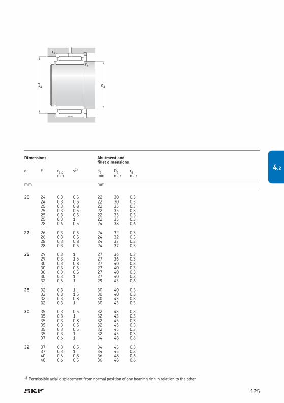
20 24 0,3 0,5 22 30 0,3 24 0,3 0,5 22 30 0,3 25 0,3 0,8 22 35 0,3 25 0,3 0,5 22 35 0,3 25 0,3 0,5 22 35 0,3 25 0,3 1 22 35 0,3 28 0,6 0,5 24 38 0,6 22 26 0,3 0,5 24 32 0,3 26 0,3 0,5 24 32 0,3 28 0,3 0,8 24 37 0,3 28 0,3 0,5 24 37 0,3 25 29 0,3 1 27 36 0,3 29 0,3 1,5 27 36 0,3 30 0,3 0,8 27 40 0,3 30 0,3 0,5 27 40 0,3 30 0,3 0,5 27 40 0,3 30 0,3 1 27 40 0,3 32 0,6 1 29 43 0,6 28 32 0,3 1 30 40 0,3 32 0,3 1,5 30 40 0,3 32 0,3 0,8 30 43 0,3 32 0,3 1 30 43 0,3 30 35 0,3 0,5 32 43 0,3 35 0,3 1 32 43 0,3 35 0,3 0,8 32 45 0,3 35 0,3 0,5 32 45 0,3 35 0,3 0,5 32 45 0,3 35 0,3 1 32 45 0,3 37 0,6 1 34 48 0,6 32 37 0,3 0,5 34 45 0,3 37 0,3 1 34 45 0,3 40 0,6 0,8 36 48 0,6 40 0,6 0,5 36 48 0,6
Dimensions Abutment and fillet dimensions
d F r1,2 s1) da Da ra min min max max mm mm
1) Permissible axial displacement from normal position of one bearing ring in relation to the other
daDa
ra
ra
125
4.2

35 50 20 – 30,3 61 7,5 10 000 11 000 0,13 NKI 35/20 TN 50 30 – 38 83 10,8 10 000 11 000 0,19 NKI 35/30 55 20 – 31,9 54 6,95 9 500 11 000 0,17 NA 4907 55 21 20 27 43 5,4 9 500 5 400 0,18 NA 4907 RS 55 21 20 27 43 5,4 – 5 400 0,18 NA 4907.2RS 55 36 – 48,4 93 11,8 9 500 11 000 0,31 NA 6907 58 22 – 39,1 61 7,8 9 000 10 000 0,22 NKIS 35 38 53 20 – 27,5 55 6,95 9 500 11 000 0,14 NKI 38/20 53 30 – 40,2 90 11,6 9 500 11 000 0,21 NKI 38/30 40 55 20 – 31,4 67 8,3 9 000 10 000 0,14 NKI 40/20 TN 55 30 – 45,7 108 13,4 9 000 10 000 0,22 NKI 40/30 TN 62 22 – 42,9 71 9,15 8 000 9 500 0,23 NA 4908 62 23 22 36,9 58,5 7,35 8 000 4 000 0,25 NA 4908 RS 62 23 22 36,9 58,5 7,35 – 4 000 0,25 NA 4908.2RS 62 40 – 67,1 125 16 8 000 9 500 0,43 NA 6908 65 22 – 42,9 72 9,15 8 000 9 000 0,28 NKIS 40 42 57 20 – 29,2 61 7,65 8 500 10 000 0,15 NKI 42/20 57 30 – 41,8 98 12,9 8 500 10 000 0,22 NKI 42/30 45 62 25 – 42,9 93 11,2 8 000 9 000 0,22 NKI 45/25 TN 62 35 – 58,3 137 17 8 000 9 000 0,31 NKI 45/35 TN 68 22 – 45,7 78 10 7 500 8 500 0,27 NA 4909 68 23 22 39,1 64 8 7 500 3 800 0,29 NA 4909 RS 68 23 22 39,1 64 8 – 3 800 0,29 NA 4909.2RS 68 40 – 70,4 137 17,3 7 500 8 500 0,50 NA 6909 72 22 – 44,6 78 10 7 000 8 000 0,34 NKIS 45 50 68 25 – 40,2 88 11,2 7 500 8 500 0,27 NKI 50/25 68 35 – 52,3 122 16 7 500 8 500 0,38 NKI 50/35 72 22 – 47,3 85 11 7 000 8 000 0,27 NA 4910 72 23 22 40,2 69,5 8,8 7 000 3 400 0,30 NA 4910 RS 72 23 22 40,2 69,5 8,8 – 3 400 0,30 NA 4910.2RS 72 40 – 73,7 150 19 7 000 8 000 0,52 NA 6910 80 28 – 62,7 104 13,7 6 300 7 500 0,52 NKIS 50
Principal Basic load ratings Fatigue Speed ratings Mass Designationdimensions dynamic static load limit Reference Limiting speed speedd D B C C C0 Pu
mm kN kN r/min kg –
Needle roller bearings with machined rings with flanges, with an inner ringd 35 – 50 mm
NA 49...2RSNA 49.. RSNA 69NKI(S)NA 49
d
B
r1
F
r1
r2
r2
D
C
B
126

35 40 0,3 0,5 37 48 0,3 40 0,3 1 37 48 0,3 42 0,6 0,8 39 51 0,6 42 0,6 0,5 39 51 0,6 42 0,6 0,5 39 51 0,6 42 0,6 0,5 39 51 0,6 43 0,6 0,5 39 54 0,6 38 43 0,3 0,5 40 51 0,3 43 0,3 1 40 51 0,3 40 45 0,3 0,5 42 53 0,3 45 0,3 1 42 53 0,3 48 0,6 1 44 58 0,6 48 0,6 0,5 44 58 0,6 48 0,6 0,5 44 58 0,6 48 0,6 0,5 44 58 0,6 50 1 0,5 45 60 1 42 47 0,3 0,5 44 55 0,3 47 0,3 1 44 55 0,3 45 50 0,6 1,5 49 58 0,6 50 0,6 2 49 58 0,6 52 0,6 1 49 64 0,6 52 0,6 0,5 49 64 0,6 52 0,6 0,5 49 64 0,6 52 0,6 0,5 49 64 0,6 55 1 0,5 50 67 1 50 55 0,6 1,5 54 64 0,6 55 0,6 2 54 64 0,6 58 0,6 1 54 68 0,6 58 0,6 0,5 54 68 0,6 58 0,6 0,5 54 68 0,6 58 0,6 0,5 54 68 0,6 60 1,1 2 56,5 73,5 1
Dimensions Abutment and fillet dimensions
d F r1,2 s1) da Da ra min min max max mm mm
1) Permissible axial displacement from normal position of one bearing ring in relation to the other
daDa
ra
ra
127
4.2
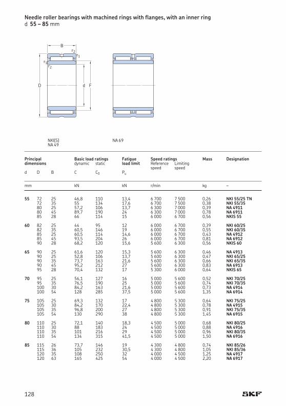
55 72 25 46,8 110 13,4 6 700 7 500 0,26 NKI 55/25 TN 72 35 55 134 17,6 6 700 7 500 0,38 NKI 55/35 80 25 57,2 106 13,7 6 300 7 000 0,39 NA 4911 80 45 89,7 190 24 6 300 7 000 0,78 NA 6911 85 28 66 114 15 6 000 6 700 0,56 NKIS 55 60 82 25 44 95 12 6 000 6 700 0,39 NKI 60/25 82 35 60,5 146 19 6 000 6 700 0,55 NKI 60/35 85 25 60,5 114 14,6 6 000 6 700 0,43 NA 4912 85 45 93,5 204 26 6 000 6 700 0,81 NA 6912 90 28 68,2 120 15,6 5 600 6 300 0,56 NKIS 60 65 90 25 61,6 120 15,3 5 600 6 300 0,46 NA 4913 90 25 52,8 106 13,7 5 600 6 300 0,47 NKI 65/25 90 35 73,7 163 21,6 5 600 6 300 0,66 NKI 65/35 90 45 95,2 212 27 5 600 6 300 0,83 NA 6913 95 28 70,4 132 17 5 300 6 000 0,64 NKIS 65 70 95 25 56,1 127 16 5 000 5 600 0,52 NKI 70/25 95 35 76,5 190 25 5 000 5 600 0,74 NKI 70/35 100 30 84,2 163 21,6 5 000 5 600 0,73 NA 4914 100 54 128 285 37,5 5 000 5 600 1,35 NA 6914 75 105 25 69,3 132 17 4 800 5 300 0,64 NKI 75/25 105 30 84,2 170 22,4 4 800 5 300 0,78 NA 4915 105 35 96,8 200 27 4 800 5 300 0,91 NKI 75/35 105 54 130 290 38 4 800 5 300 1,45 NA 6915 80 110 25 72,1 140 18,3 4 500 5 000 0,68 NKI 80/25 110 30 88 183 24 4 500 5 000 0,88 NA 4916 110 35 101 216 29 4 500 5 000 0,96 NKI 80/35 110 54 134 315 41,5 4 500 5 000 1,50 NA 6916 85 115 26 73,7 146 19 4 300 4 800 0,74 NKI 85/26 115 36 105 232 30,5 4 300 4 800 1,05 NKI 85/36 120 35 108 250 32 4 000 4 500 1,25 NA 4917 120 63 165 425 54 4 000 4 500 2,20 NA 6917
Principal Basic load ratings Fatigue Speed ratings Mass Designationdimensions dynamic static load limit Reference Limiting speed speedd D B C C0 Pu
mm kN kN r/min kg –
Needle roller bearings with machined rings with flanges, with an inner ringd 55 – 85 mm
NKI(S)NA 49
d
B
r1
F
r1
r2
r2
D
NA 69
128

55 60 0,6 1,5 59 68 0,6 60 0,6 2 59 68 0,6 63 1 1,5 60 75 1 63 1 1,5 60 75 1 65 1,1 2 61,5 78,5 1 60 68 0,6 1 64 78 0,6 68 0,6 1 64 78 0,6 68 1 1,5 65 80 1 68 1 1,5 65 80 1 70 1,1 2 66,5 83,5 1 65 72 1 1,5 70 85 1 73 1 1 70 85 1 73 1 1 70 85 1 72 1 1,5 70 85 1 75 1,1 2 71,5 88,5 1 70 80 1 0,8 75 90 1 80 1 0,8 75 90 1 80 1 1,5 75 95 1 80 1 1 75 95 1 75 85 1 1 80 100 1 85 1 1,5 80 100 1 85 1 1 80 100 1 85 1 1 80 100 1 80 90 1 1 85 105 1 90 1 1,5 85 105 1 90 1 1 85 105 1 90 1 1 85 105 1 85 95 1 1,5 90 110 1 95 1 1,5 90 110 1 100 1,1 1 91,5 113,5 1 100 1,1 1 91,5 113,5 1
Dimensions Abutment and fillet dimensions
d F r1,2 s1) da Da ra min min max max mm mm
1) Permissible axial displacement from normal position of one bearing ring in relation to the other
daDa
ra
ra
129
4.2
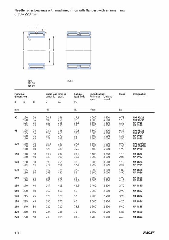
90 120 26 76,5 156 19,6 4 000 4 500 0,78 NKI 90/26 120 36 108 250 32 4 000 4 500 1,10 NKI 90/36 125 35 112 265 33,5 3 800 4 300 1,30 NA 4918 125 63 172 450 57 3 800 4 300 2,30 NA 6918 95 125 26 78,1 166 20,8 3 800 4 300 0,82 NKI 95/26 125 36 112 265 33,5 3 800 4 300 1,15 NKI 95/36 130 35 114 270 34 3 600 4 000 1,35 NA 4919 130 63 172 465 57 3 600 4 000 2,50 NA 6919 100 130 30 96,8 220 27,5 3 600 4 000 0,99 NKI 100/30 130 40 123 305 38 3 600 4 000 1,35 NKI 100/40 140 40 125 280 34,5 3 400 4 000 1,90 NA 4920 110 140 30 93,5 232 27,5 3 400 3 800 1,10 NA 4822 150 40 130 300 36,5 3 200 3 600 2,05 NA 4922 120 150 30 99 255 30 3 200 3 600 1,15 NA 4824 165 45 176 405 47,5 3 000 3 400 2,85 NA 4924 130 165 35 119 325 37,5 2 800 3 200 1,80 NA 4826 180 50 198 480 55 2 600 3 000 3,90 NA 4926 140 175 35 121 345 38 2 600 3 000 1,90 NA 4828 190 50 205 510 58,5 2 400 2 800 4,15 NA 4928 150 190 40 147 415 46,5 2 400 2 800 2,70 NA 4830 160 200 40 157 450 50 2 200 2 600 2,90 NA 4832 170 215 45 179 520 57 2 200 2 400 3,95 NA 4834 180 225 45 190 570 60 2 000 2 400 4,20 NA 4836 190 240 50 220 710 73,5 1 900 2 200 5,60 NA 4838 200 250 50 224 735 75 1 800 2 000 5,85 NA 4840 220 270 50 238 815 81,5 1 700 1 900 6,40 NA 4844
Principal Basic load ratings Fatigue Speed ratings Mass Designationdimensions dynamic static load limit Reference Limiting speed speedd D B C C0 Pu
mm kN kN r/min kg –
Needle roller bearings with machined rings with flanges, with an inner ringd 90 – 220 mm
NA 69NKINA 48NA 49
d
B
r1
F
r1
r2
r2
D
130

90 100 1 1,5 95 115 1 100 1 1,5 95 115 1 105 1,1 1 96,5 118,5 1 105 1,1 1 96,5 118,5 1 95 105 1 1,5 100 120 1 105 1 1,5 100 120 1 110 1,1 1 101,5 123,5 1 110 1,1 1 101,5 123,5 1 100 110 1,1 1,5 106,5 123,5 1 110 1,1 2 106,5 123,5 1 115 1,1 2 106,5 133,5 1 110 120 1 0,8 115 135 1 125 1,1 2 116,5 143,5 1 120 130 1 0,8 125 145 1 135 1,1 2 126,5 158,5 1 130 145 1,1 1 136,5 158,5 1 150 1,5 1,5 138 172 1,5 140 155 1,1 1 146,5 168,5 1 160 1,5 1,5 148 182 1,5 150 165 1,1 1,5 156,5 183,5 1 160 175 1,1 1,5 166,5 193,5 1 170 185 1,1 1,5 176,5 208,5 1 180 195 1,1 1,5 186,5 218,5 1 190 210 1,5 1,5 198 232 1,5 200 220 1,5 1,5 208 242 1,5 220 240 1,5 1,5 228 262 1,5
Dimensions Abutment and fillet dimensions
d F r1,2 s1) da Da ra min min max max mm mm
1) Permissible axial displacement from normal position of one bearing ring in relation to the other
daDa
ra
ra
131
4.2
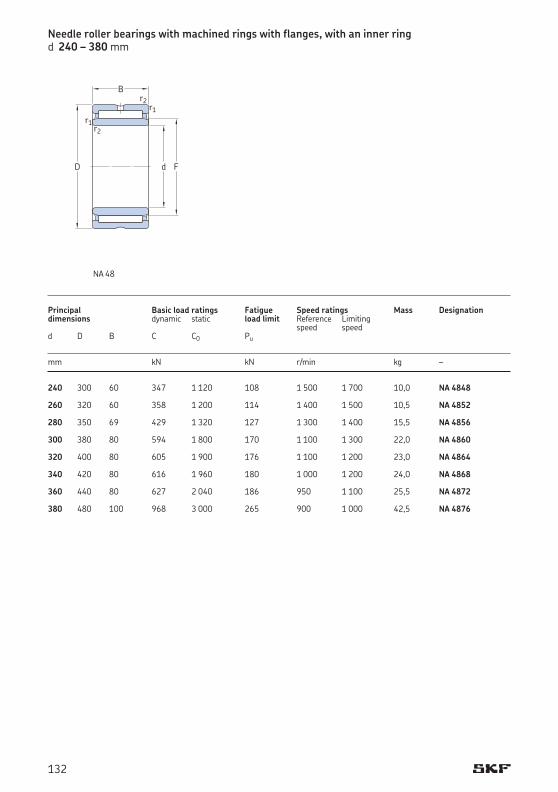
240 300 60 347 1 120 108 1 500 1 700 10,0 NA 4848 260 320 60 358 1 200 114 1 400 1 500 10,5 NA 4852 280 350 69 429 1 320 127 1 300 1 400 15,5 NA 4856 300 380 80 594 1 800 170 1 100 1 300 22,0 NA 4860 320 400 80 605 1 900 176 1 100 1 200 23,0 NA 4864 340 420 80 616 1 960 180 1 000 1 200 24,0 NA 4868 360 440 80 627 2 040 186 950 1 100 25,5 NA 4872 380 480 100 968 3 000 265 900 1 000 42,5 NA 4876
Principal Basic load ratings Fatigue Speed ratings Mass Designationdimensions dynamic static load limit Reference Limiting speed speedd D B C C0 Pu
mm kN kN r/min kg –
Needle roller bearings with machined rings with flanges, with an inner ringd 240 – 380 mm
NA 48
d
B
r1
F
r1
r2
r2
D
132
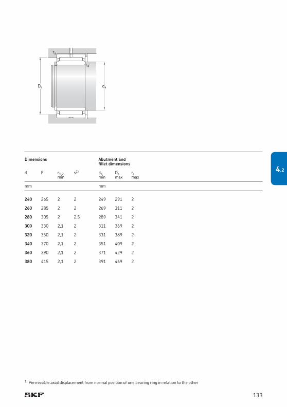
240 265 2 2 249 291 2 260 285 2 2 269 311 2 280 305 2 2,5 289 341 2 300 330 2,1 2 311 369 2 320 350 2,1 2 331 389 2 340 370 2,1 2 351 409 2 360 390 2,1 2 371 429 2 380 415 2,1 2 391 469 2
Dimensions Abutment and fillet dimensions
d F r1,2 s1) da Da ra min min max max mm mm
1) Permissible axial displacement from normal position of one bearing ring in relation to the other
daDa
ra
ra
133
4.2
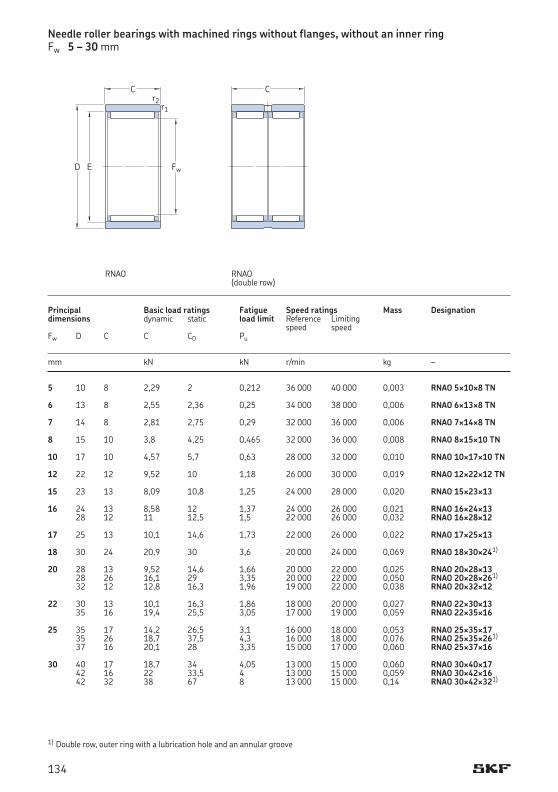
Needle roller bearings with machined rings without flanges, without an inner ringFw 5 – 30 mm
5 10 8 2,29 2 0,212 36 000 40 000 0,003 RNAO 5¥10¥8 TN 6 13 8 2,55 2,36 0,25 34 000 38 000 0,006 RNAO 6¥13¥8 TN 7 14 8 2,81 2,75 0,29 32 000 36 000 0,006 RNAO 7¥14¥8 TN 8 15 10 3,8 4,25 0,465 32 000 36 000 0,008 RNAO 8¥15¥10 TN 10 17 10 4,57 5,7 0,63 28 000 32 000 0,010 RNAO 10¥17¥10 TN 12 22 12 9,52 10 1,18 26 000 30 000 0,019 RNAO 12¥22¥12 TN 15 23 13 8,09 10,8 1,25 24 000 28 000 0,020 RNAO 15¥23¥13 16 24 13 8,58 12 1,37 24 000 26 000 0,021 RNAO 16¥24¥13 28 12 11 12,5 1,5 22 000 26 000 0,032 RNAO 16¥28¥12 17 25 13 10,1 14,6 1,73 22 000 26 000 0,022 RNAO 17¥25¥13 18 30 24 20,9 30 3,6 20 000 24 000 0,069 RNAO 18¥30¥241)
20 28 13 9,52 14,6 1,66 20 000 22 000 0,025 RNAO 20¥28¥13 28 26 16,1 29 3,35 20 000 22 000 0,050 RNAO 20¥28¥261)
32 12 12,8 16,3 1,96 19 000 22 000 0,038 RNAO 20¥32¥12 22 30 13 10,1 16,3 1,86 18 000 20 000 0,027 RNAO 22¥30¥13 35 16 19,4 25,5 3,05 17 000 19 000 0,059 RNAO 22¥35¥16 25 35 17 14,2 26,5 3,1 16 000 18 000 0,053 RNAO 25¥35¥17 35 26 18,7 37,5 4,3 16 000 18 000 0,076 RNAO 25¥35¥261)
37 16 20,1 28 3,35 15 000 17 000 0,060 RNAO 25¥37¥16 30 40 17 18,7 34 4,05 13 000 15 000 0,060 RNAO 30¥40¥17 42 16 22 33,5 4 13 000 15 000 0,059 RNAO 30¥42¥16 42 32 38 67 8 13 000 15 000 0,14 RNAO 30¥42¥321)
1) Double row, outer ring with a lubrication hole and an annular groove
C
Fw
r1r2
ED
RNAO
Principal Basic load ratings Fatigue Speed ratings Mass Designationdimensions dynamic static load limit Reference Limiting speed speedFw D C C C0 Pu
mm kN kN r/min kg –
C
RNAO (double row)
134
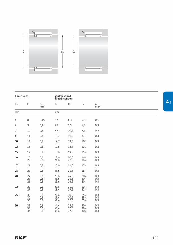
daDa
ra
Db
ra
5 8 0,15 7,7 8,3 5,3 0,1 6 9 0,3 8,7 9,3 6,3 0,3 7 10 0,3 9,7 10,3 7,3 0,3 8 11 0,3 10,7 11,3 8,3 0,3 10 13 0,3 12,7 13,3 10,3 0,3 12 18 0,3 17,6 18,3 12,3 0,3 15 19 0,3 18,6 19,3 15,4 0,3 16 20 0,3 19,6 20,3 16,4 0,3 22 0,3 21,6 22,3 16,4 0,3 17 21 0,3 20,6 21,3 17,4 0,3 18 24 0,3 23,6 24,5 18,4 0,3 20 24 0,3 23,6 24,3 20,4 0,3 24 0,3 23,6 24,3 20,4 0,3 26 0,3 25,6 26,5 20,4 0,3 22 26 0,3 25,6 26,3 22,4 0,3 29 0,3 28,4 29,5 22,4 0,3 25 30 0,3 29,4 30,5 25,6 0,3 30 0,3 29,4 30,5 25,6 0,3 32 0,3 31,4 32,5 25,6 0,3 30 35 0,3 34,4 35,5 30,6 0,3 37 0,3 36,4 37,5 30,6 0,3 37 0,3 36,4 37,5 30,6 0,3
Dimensions Abutment and fillet dimensions
Fw E r1,2 da Da Db ra min max
mm mm
135
4.3
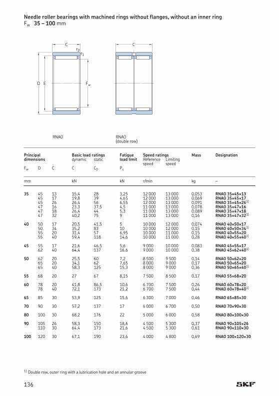
35 45 13 15,4 28 3,25 12 000 13 000 0,053 RNAO 35¥45¥13 45 17 19,8 39 4,65 12 000 13 000 0,069 RNAO 35¥45¥17 45 26 26,4 56 6,55 12 000 13 000 0,091 RNAO 35¥45¥261)
47 16 23,3 37,5 4,5 11 000 13 000 0,078 RNAO 35¥47¥16 47 18 26,4 44 5,3 11 000 13 000 0,089 RNAO 35¥47¥18 47 32 40,2 75 9 11 000 13 000 0,16 RNAO 35¥47¥321)
40 50 17 20,5 41,5 5 10 000 12 000 0,074 RNAO 40¥50¥17 50 34 35,2 83 10 10 000 12 000 0,15 RNAO 40¥50¥341)
55 20 31,4 57 6,95 10 000 11 000 0,15 RNAO 40¥55¥20 55 40 59,4 118 14,6 10 000 11 000 0,28 RNAO 40¥55¥401)
45 55 17 21,6 46,5 5,6 9 000 10 000 0,083 RNAO 45¥55¥17 62 40 64,4 137 16,6 9 000 10 000 0,38 RNAO 45¥62¥401)
50 62 20 25,5 60 7,2 8 500 9 500 0,14 RNAO 50¥62¥20 65 20 34,1 62 7,65 8 000 9 000 0,17 RNAO 50¥65¥20 65 40 58,3 125 15,3 8 000 9 000 0,36 RNAO 50¥65¥401)
55 68 20 27 67 8,15 7 500 8 500 0,17 RNAO 55¥68¥20 60 78 20 41,8 86,5 10,6 6 700 7 500 0,26 RNAO 60¥78¥20 78 40 72,1 173 21,2 6 700 7 500 0,44 RNAO 60¥78¥401)
65 85 30 53,9 125 15,6 6 300 7 000 0,46 RNAO 65¥85¥30 70 90 30 57,2 137 17 6 000 6 700 0,50 RNAO 70¥90¥30 80 100 30 68,2 176 22 5 000 6 000 0,58 RNAO 80¥100¥30 90 105 26 58,3 150 18,6 4 500 5 300 0,37 RNAO 90¥105¥26 110 30 64,4 173 21,6 4 500 5 300 0,61 RNAO 90¥110¥30 100 120 30 67,1 190 23,6 4 000 4 800 0,69 RNAO 100¥120¥30
1) Double row, outer ring with a lubrication hole and an annular groove
Needle roller bearings with machined rings without flanges, without an inner ringFw 35 – 100 mm
Principal Basic load ratings Fatigue Speed ratings Mass Designationdimensions dynamic static load limit Reference Limiting speed speedFw D C C C0 Pu
mm kN kN r/min kg –
C
Fw
r1r2
ED
RNAO
C
RNAO (double row)
136
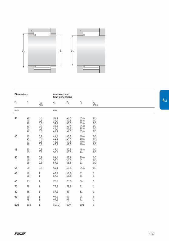
35 40 0,3 39,4 40,5 35,6 0,3 40 0,3 39,4 40,5 35,6 0,3 40 0,3 39,4 40,5 35,6 0,3 42 0,3 41,4 42,5 35,8 0,3 42 0,3 41,4 42,5 35,6 0,3 42 0,3 41,4 42,5 35,6 0,3 40 45 0,3 44,4 45,5 40,6 0,3 45 0,3 44,4 45,5 40,6 0,3 47 0,3 46,2 47,5 40,6 0,3 48 0,3 47,2 47,5 40,6 0,3 45 50 0,3 49,4 50,5 45,6 0,3 53 0,3 52,2 53,5 46 0,3 50 55 0,3 54,4 55,8 50,6 0,3 58 0,3 57,2 58,5 51 0,3 58 0,3 57,2 58,5 51 0,3 55 60 0,3 59,4 60,8 55,6 0,3 60 68 1 67,2 68,8 61 1 68 1 67,2 68,8 61 1 65 73 1 72,2 73,8 66 1 70 78 1 77,2 78,8 71 1 80 88 1 87,2 89 81 1 90 98 1 97,2 99 91 1 98 1 97,2 99 91 1 100 108 1 107,2 109 101 1
Dimensions Abutment and fillet dimensions
Fw E r1,2 da Da Db ra min max
mm mm
daDa
ra
Db
ra
137
4.3
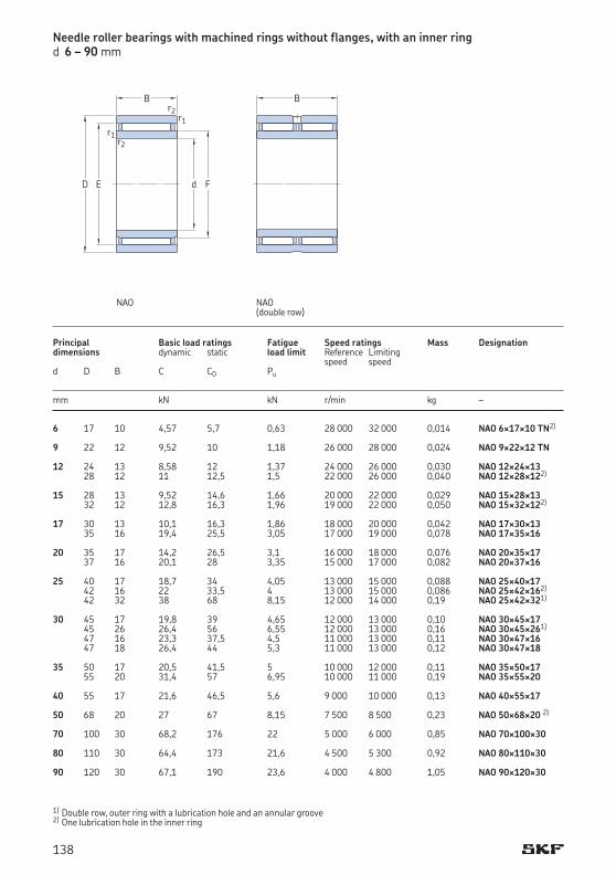
NAO(double row)
NAO
Needle roller bearings with machined rings without flanges, with an inner ringd 6 – 90 mm
B
d
r1
F
r1
r2
r2
ED
B
6 17 10 4,57 5,7 0,63 28 000 32 000 0,014 NAO 6¥17¥10 TN2)
9 22 12 9,52 10 1,18 26 000 28 000 0,024 NAO 9¥22¥12 TN 12 24 13 8,58 12 1,37 24 000 26 000 0,030 NAO 12¥24¥13 28 12 11 12,5 1,5 22 000 26 000 0,040 NAO 12¥28¥122)
15 28 13 9,52 14,6 1,66 20 000 22 000 0,029 NAO 15¥28¥13 32 12 12,8 16,3 1,96 19 000 22 000 0,050 NAO 15¥32¥122)
17 30 13 10,1 16,3 1,86 18 000 20 000 0,042 NAO 17¥30¥13 35 16 19,4 25,5 3,05 17 000 19 000 0,078 NAO 17¥35¥16 20 35 17 14,2 26,5 3,1 16 000 18 000 0,076 NAO 20¥35¥17 37 16 20,1 28 3,35 15 000 17 000 0,082 NAO 20¥37¥16 25 40 17 18,7 34 4,05 13 000 15 000 0,088 NAO 25¥40¥17 42 16 22 33,5 4 13 000 15 000 0,086 NAO 25¥42¥162)
42 32 38 68 8,15 12 000 14 000 0,19 NAO 25¥42¥321)
30 45 17 19,8 39 4,65 12 000 13 000 0,10 NAO 30¥45¥17 45 26 26,4 56 6,55 12 000 13 000 0,16 NAO 30¥45¥261)
47 16 23,3 37,5 4,5 11 000 13 000 0,11 NAO 30¥47¥16 47 18 26,4 44 5,3 11 000 13 000 0,12 NAO 30¥47¥18 35 50 17 20,5 41,5 5 10 000 12 000 0,11 NAO 35¥50¥17 55 20 31,4 57 6,95 10 000 11 000 0,19 NAO 35¥55¥20 40 55 17 21,6 46,5 5,6 9 000 10 000 0,13 NAO 40¥55¥17 50 68 20 27 67 8,15 7 500 8 500 0,23 NAO 50¥68¥20 2)
70 100 30 68,2 176 22 5 000 6 000 0,85 NAO 70¥100¥30 80 110 30 64,4 173 21,6 4 500 5 300 0,92 NAO 80¥110¥30 90 120 30 67,1 190 23,6 4 000 4 800 1,05 NAO 90¥120¥30
1) Double row, outer ring with a lubrication hole and an annular groove2) One lubrication hole in the inner ring
Principal Basic load ratings Fatigue Speed ratings Mass Designationdimensions dynamic static load limit Reference Limiting speed speed d D B C C0 Pu mm kN kN r/min kg –
138
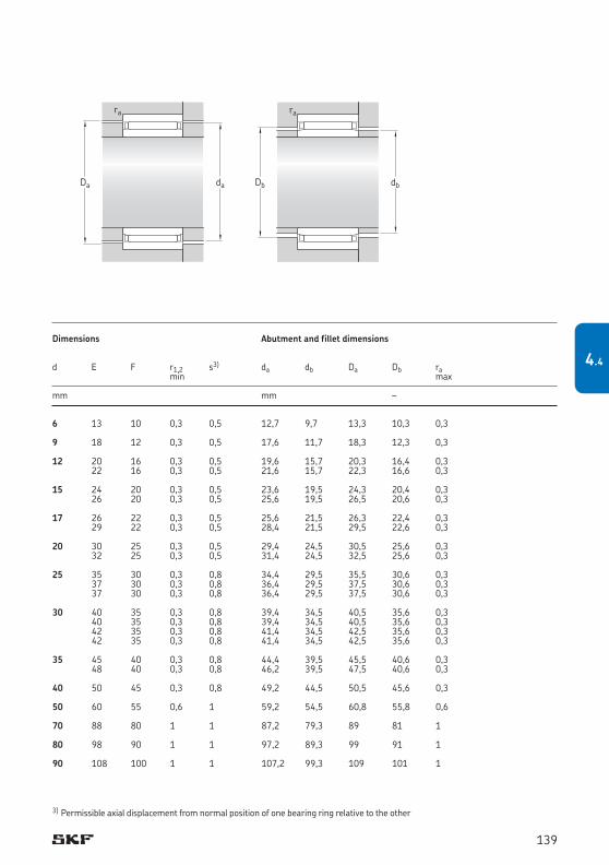
daDa
ra
dbDb
ra
6 13 10 0,3 0,5 12,7 9,7 13,3 10,3 0,3 9 18 12 0,3 0,5 17,6 11,7 18,3 12,3 0,3 12 20 16 0,3 0,5 19,6 15,7 20,3 16,4 0,3 22 16 0,3 0,5 21,6 15,7 22,3 16,6 0,3 15 24 20 0,3 0,5 23,6 19,5 24,3 20,4 0,3 26 20 0,3 0,5 25,6 19,5 26,5 20,6 0,3 17 26 22 0,3 0,5 25,6 21,5 26,3 22,4 0,3 29 22 0,3 0,5 28,4 21,5 29,5 22,6 0,3 20 30 25 0,3 0,5 29,4 24,5 30,5 25,6 0,3 32 25 0,3 0,5 31,4 24,5 32,5 25,6 0,3 25 35 30 0,3 0,8 34,4 29,5 35,5 30,6 0,3 37 30 0,3 0,8 36,4 29,5 37,5 30,6 0,3 37 30 0,3 0,8 36,4 29,5 37,5 30,6 0,3 30 40 35 0,3 0,8 39,4 34,5 40,5 35,6 0,3 40 35 0,3 0,8 39,4 34,5 40,5 35,6 0,3 42 35 0,3 0,8 41,4 34,5 42,5 35,6 0,3 42 35 0,3 0,8 41,4 34,5 42,5 35,6 0,3 35 45 40 0,3 0,8 44,4 39,5 45,5 40,6 0,3 48 40 0,3 0,8 46,2 39,5 47,5 40,6 0,3 40 50 45 0,3 0,8 49,2 44,5 50,5 45,6 0,3 50 60 55 0,6 1 59,2 54,5 60,8 55,8 0,6 70 88 80 1 1 87,2 79,3 89 81 1 80 98 90 1 1 97,2 89,3 99 91 1 90 108 100 1 1 107,2 99,3 109 101 1
Dimensions Abutment and fillet dimensions d E F r1,2 s3) da db Da Db ra min max mm mm –
3) Permissible axial displacement from normal position of one bearing ring relative to the other
139
4.4
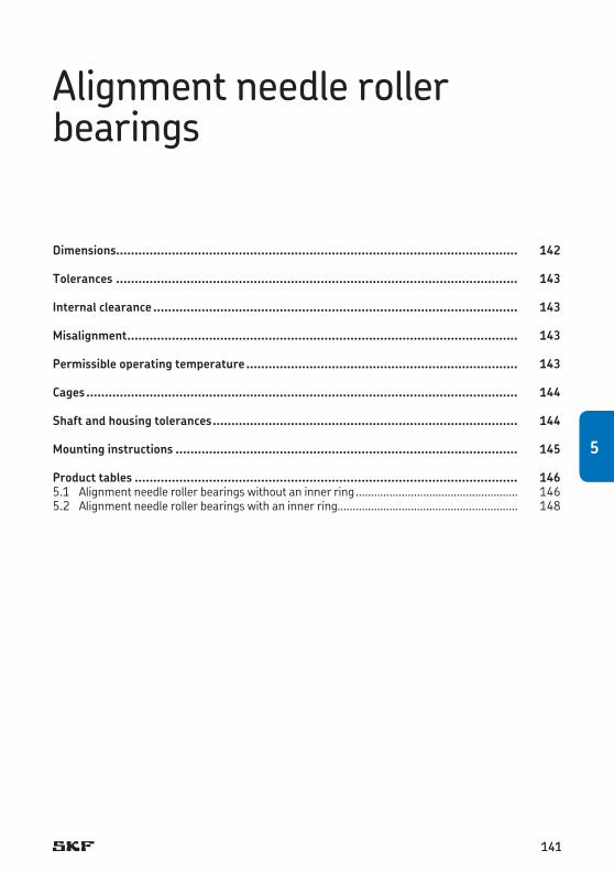
Dimensions............................................................................................................ 142
Tolerances ............................................................................................................ 143
Internal clearance .................................................................................................. 143
Misalignment ......................................................................................................... 143
Permissible operating temperature ......................................................................... 143
Cages .................................................................................................................... 144
Shaft and housing tolerances .................................................................................. 144
Mounting instructions ............................................................................................ 145
Product tables ....................................................................................................... 1465.1 Alignment needle roller bearings without an inner ring ..................................................... 1465.2 Alignment needle roller bearings with an inner ring........................................................... 148
Alignment needle roller bearings
5
141141
5
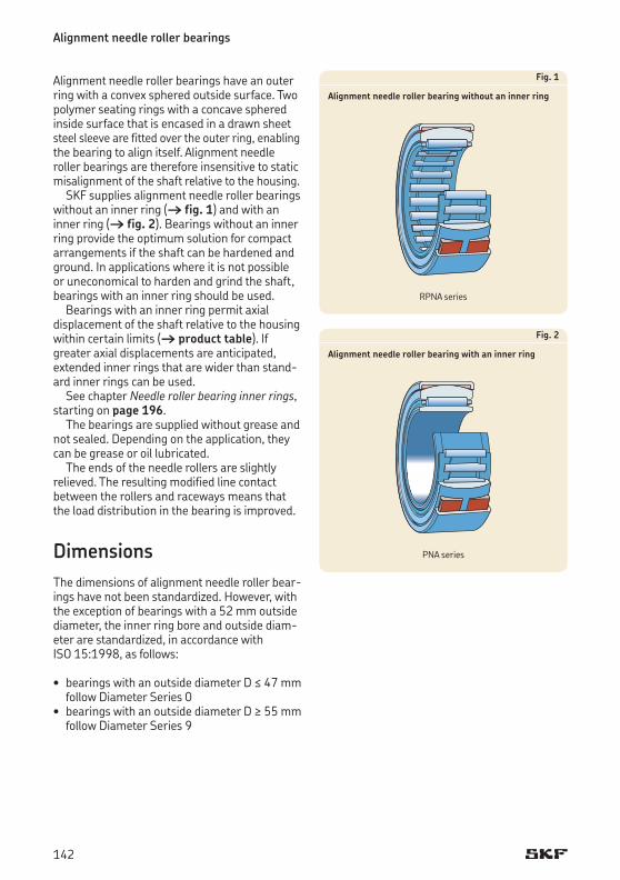
Alignment needle roller bearings
Alignment needle roller bearings have an outer ring with a convex sphered outside surface. Two polymer seating rings with a concave sphered inside surface that is encased in a drawn sheet steel sleeve are fitted over the outer ring, en abling the bearing to align itself. Alignment needle roller bearings are therefore insensitive to static misalignment of the shaft relative to the housing.
SKF supplies alignment needle roller bearings without an inner ring († fig. 1) and with an inner ring († fig. 2). Bearings without an inner ring provide the optimum solution for compact arrangements if the shaft can be hardened and ground. In applications where it is not possible or uneconomical to harden and grind the shaft, bearings with an inner ring should be used.
Bearings with an inner ring permit axial displace ment of the shaft relative to the housing within certain limits († product table). If greater axial displacements are anticipated, extended inner rings that are wider than stand-ard inner rings can be used.
See chapter Needle roller bearing inner rings, starting on page 196.
The bearings are supplied without grease and not sealed. Depending on the application, they can be grease or oil lubricated.
The ends of the needle rollers are slightly relieved. The resulting modified line contact between the rollers and raceways means that the load distribution in the bearing is improved.
DimensionsThe dimensions of alignment needle roller bear-ingshavenotbeenstandardized.However,withthe exception of bearings with a 52 mm outside diameter, the inner ring bore and outside diam-eter are standardized, in accordance with ISO 15:1998, as follows:
• bearingswithanoutsidediameterD ≤ 47 mm follow Diameter Series 0 • bearingswithanoutsidediameterD ≥ 55 mm
follow Diameter Series 9
Fig. 1
Alignment needle roller bearing without an inner ring
Fig. 2
Alignment needle roller bearing with an inner ring
RPNA series
PNA series
142
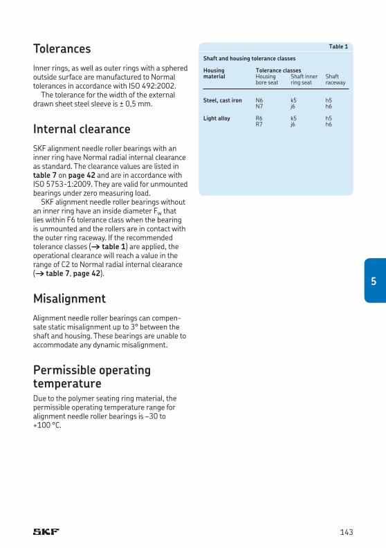
TolerancesInner rings, as well as outer rings with a sphered outside surface are manufactured to Normal tolerances in accordance with ISO 492:2002.
The tolerance for the width of the external drawn sheet steel sleeve is ± 0,5 mm.
Internal clearanceSKF alignment needle roller bearings with an inner ring have Normal radial internal clearance as standard. The clearance values are listed in table 7 on page 42 and are in accordance with ISO 5753-1:2009. They are valid for unmounted bearings under zero measuring load.
SKF alignment needle roller bearings without an inner ring have an inside diameter Fw that lies within F6 tolerance class when the bearing is unmounted and the rollers are in contact with the outer ring raceway. If the recommended tolerance classes († table 1) are applied, the oper ational clearance will reach a value in the range of C2 to Normal radial internal clearance († table 7, page 42).
MisalignmentAlignment needle roller bearings can compen-sate static misalignment up to 3° between the shaft and housing. These bearings are unable to accommodate any dynamic misalignment.
Permissible operating temperatureDue to the polymer seating ring material, the permissible operating temperature range for alignment needle roller bearings is –30 to +100 °C.
Table 1
Shaft and housing tolerance classes
Housing Tolerance classesmaterial Housing Shaftinner Shaft bore seat ring seat raceway
Steel, cast iron N6 k5 h5 N7 j6 h6
Light alloy R6 k5 h5 R7 j6 h6
143
5
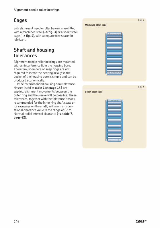
Alignment needle roller bearings
Fig. 3
Machined steel cage
Fig. 4
Sheet steel cage
CagesSKF alignment needle roller bearings are fitted with a machined steel († fig. 3) or a sheet steel cage († fig. 4), with adequate free space for lubricant.
Shaft and housing tolerancesAlignment needle roller bearings are mounted with an interference fit in the housing bore. Therefore, shoulders or snap rings are not required to locate the bearing axially so the design of the housing bore is simple and can be produced economically.
If the recommended housing bore tolerance classes listed in table 1 on page 143 are applied, alignment movements between the outer ring and the sleeve will be possible. These tolerances, together with the tolerance classes recommended for the inner ring shaft seats or for raceways on the shaft, will reach an oper-ational clearance value in the range of C2 to Normal radial internal clearance († table 7, page 42).
144
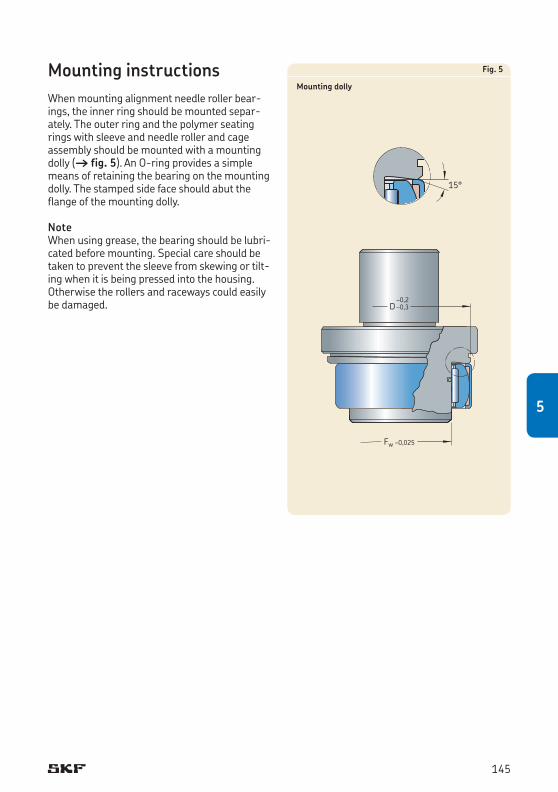
Fig. 5
Mounting dolly
Fw –0,025
D–0,2–0,3
15°
Mounting instructionsWhen mounting alignment needle roller bear-ings, the inner ring should be mounted separ-ately. The outer ring and the polymer seating rings with sleeve and needle roller and cage assembly should be mounted with a mounting dolly († fig. 5). An O-ring provides a simple means of retaining the bearing on the mounting dolly. The stamped side face should abut the flange of the mounting dolly.
NoteWhen using grease, the bearing should be lubri-cated before mounting. Special care should be taken to prevent the sleeve from skewing or tilt-ing when it is being pressed into the housing. Otherwise the rollers and raceways could easily be damaged.
145
5
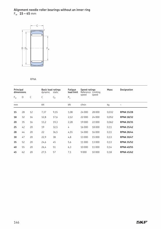
RPNA
15 28 12 7,37 9,15 1,08 24 000 28 000 0,032 RPNA 15/28 18 32 16 12,8 17,6 2,12 22 000 24 000 0,052 RPNA 18/32 20 35 16 13,2 19,3 2,28 19 000 22 000 0,062 RPNA 20/35 25 42 20 19 32,5 4 16 000 18 000 0,11 RPNA 25/42 28 44 20 22 36,5 4,55 14 000 16 000 0,11 RPNA 28/44 30 47 20 22,9 38 4,8 13 000 15 000 0,13 RPNA 30/47 35 52 20 24,6 45 5,6 11 000 13 000 0,13 RPNA 35/52 40 55 20 26,4 51 6,3 10 000 11 000 0,14 RPNA 40/55 45 62 20 27,5 57 7,1 9 000 10 000 0,18 RPNA 45/62
Principal Basic load ratings Fatigue Speed ratings Mass Designationdimensions dynamic static load limit Reference Limiting speed speed Fw D C C C0 Pu mm kN kN r/min kg –
Alignment needle roller bearings without an inner ringFw 15 – 45 mm
C
r
FwD D1
146
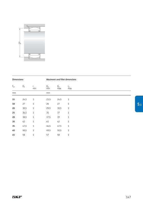
15 24,5 1 23,5 24,5 1 18 27 1 26 27 1 20 30,5 1 29,5 30,5 1 25 36,5 1 35 37 1 28 38,5 1 37,5 39 1 30 42 1 41 42 1 35 47,5 1 46,5 47,5 1 40 50,5 1 49,5 50,5 1 45 58 1 57 58 1
Dimensions Abutment and fillet dimensions Fw D1 r Da Da ra min min max max mm mm
Da
ra
147
5.1
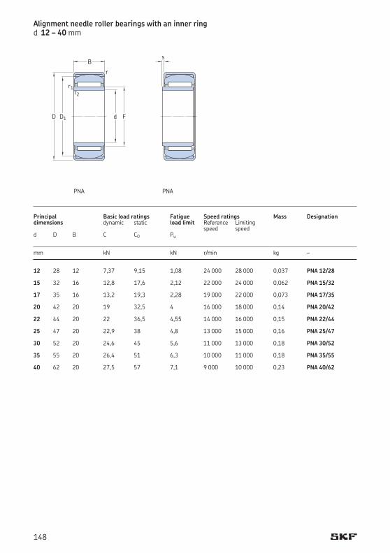
PNA PNA
Alignment needle roller bearings with an inner ringd 12 – 40 mm
12 28 12 7,37 9,15 1,08 24 000 28 000 0,037 PNA 12/28 15 32 16 12,8 17,6 2,12 22 000 24 000 0,062 PNA 15/32 17 35 16 13,2 19,3 2,28 19 000 22 000 0,073 PNA 17/35 20 42 20 19 32,5 4 16 000 18 000 0,14 PNA 20/42 22 44 20 22 36,5 4,55 14 000 16 000 0,15 PNA 22/44 25 47 20 22,9 38 4,8 13 000 15 000 0,16 PNA 25/47 30 52 20 24,6 45 5,6 11 000 13 000 0,18 PNA 30/52 35 55 20 26,4 51 6,3 10 000 11 000 0,18 PNA 35/55 40 62 20 27,5 57 7,1 9 000 10 000 0,23 PNA 40/62
Principal Basic load ratings Fatigue Speed ratings Mass Designationdimensions dynamic static load limit Reference Limiting speed speed d D B C C0 Pu mm kN kN r/min kg –
d
B
r
r1
FD1
r2
D
s
148
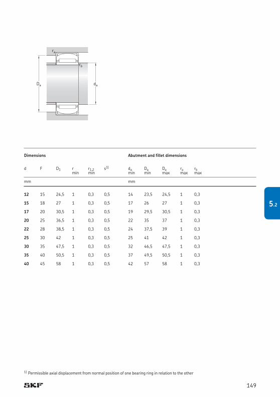
daDa
ra
rb
12 15 24,5 1 0,3 0,5 14 23,5 24,5 1 0,3 15 18 27 1 0,3 0,5 17 26 27 1 0,3 17 20 30,5 1 0,3 0,5 19 29,5 30,5 1 0,3 20 25 36,5 1 0,3 0,5 22 35 37 1 0,3 22 28 38,5 1 0,3 0,5 24 37,5 39 1 0,3 25 30 42 1 0,3 0,5 25 41 42 1 0,3 30 35 47,5 1 0,3 0,5 32 46,5 47,5 1 0,3 35 40 50,5 1 0,3 0,5 37 49,5 50,5 1 0,3 40 45 58 1 0,3 0,5 42 57 58 1 0,3
Dimensions Abutment and fillet dimensions d F D1 r r1,2 s1) da Da Da ra rb min min min min max max max
mm mm
1) Permissible axial displacement from normal position of one bearing ring in relation to the other
149
5.2
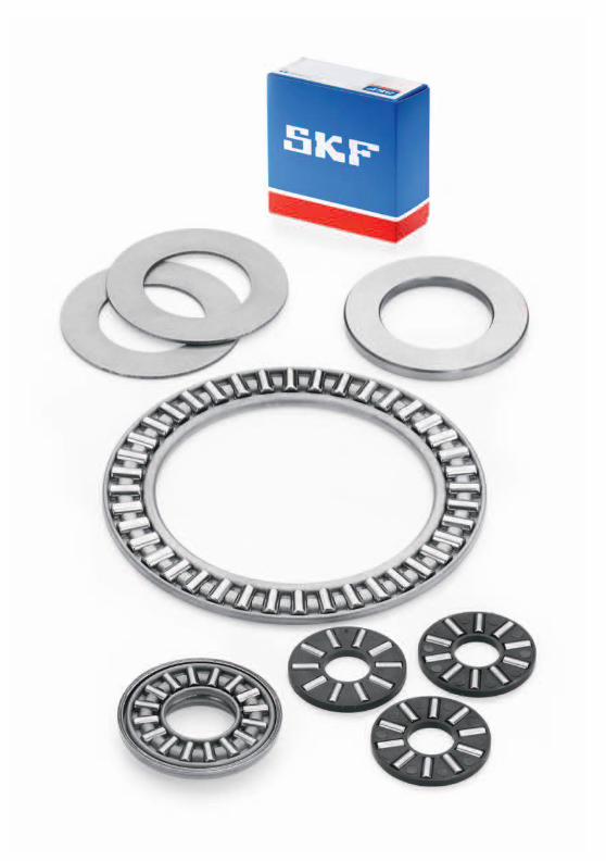
Needle roller and cage thrust assemblies, AXK series ................................................ 153
Needle roller thrust bearings with a centring spigot, AXW series ................................ 154
Bearing washers .................................................................................................... 154
Dimensions............................................................................................................ 157
Tolerances ............................................................................................................ 157
Misalignment ......................................................................................................... 157
Cages .................................................................................................................... 158
Design of associated components ............................................................................ 159
Raceways on a shaft and in a housing ...................................................................... 160
Supplementary designations ................................................................................... 160
Product tables ....................................................................................................... 1626.1 Needle roller and cage thrust assemblies and appropriate washers ................................. 1626.2 Needle roller thrust bearings with a centring spigot and appropriate washers ................ 166
Needle roller thrust bearings and bearing washers
6
151151
6
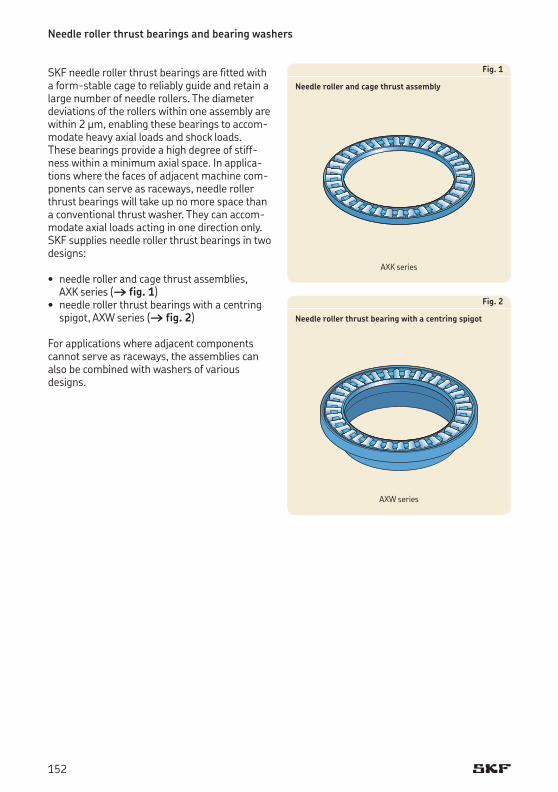
Needle roller thrust bearings and bearing washers
SKF needle roller thrust bearings are fitted with a form-stable cage to reliably guide and retain a large number of needle rollers. The diameter deviations of the rollers within one assembly are within 2 μm, enabling these bearings to accom-modate heavy axial loads and shock loads. These bearings provide a high degree of stiff-ness within a minimum axial space. In applica-tionswherethefacesofadjacentmachinecom-ponents can serve as raceways, needle roller thrust bearings will take up no more space than a conventional thrust washer. They can accom-modate axial loads acting in one direction only. SKF supplies needle roller thrust bearings in two designs: • needlerollerandcagethrustassemblies,
AXK series († fig. 1)• needlerollerthrustbearingswithacentring
spigot, AXW series († fig. 2)
Forapplicationswhereadjacentcomponentscannot serve as raceways, the assemblies can also be combined with washers of various designs.
Fig. 1
Needle roller and cage thrust assembly
Fig. 2
Needle roller thrust bearing with a centring spigot
AXK series
AXW series
152
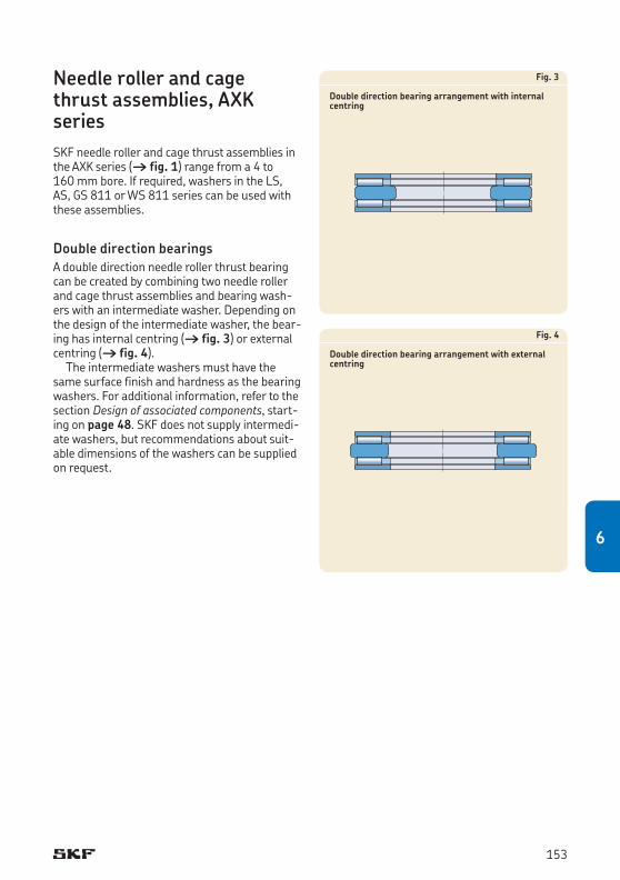
Fig. 3
Double direction bearing arrangement with internal centring
Fig. 4
Double direction bearing arrangement with external centring
Needle roller and cage thrust assemblies, AXK seriesSKF needle roller and cage thrust assemblies in the AXK series († fig. 1) range from a 4 to 160 mm bore. If required, washers in the LS, AS, GS 811 or WS 811 series can be used with these assemblies.
Double direction bearingsA double direction needle roller thrust bearing can be created by combining two needle roller and cage thrust assemblies and bearing wash-ers with an intermediate washer. Depending on the design of the intermediate washer, the bear-ing has internal centring († fig. 3) or external centring († fig. 4).
The intermediate washers must have the same surface finish and hardness as the bearing washers. For additional information, refer to the section Design of associated components, start-ing on page 48. SKF does not supply intermedi-ate washers, but recommendations about suit-able dimensions of the washers can be supplied on request.
153
6
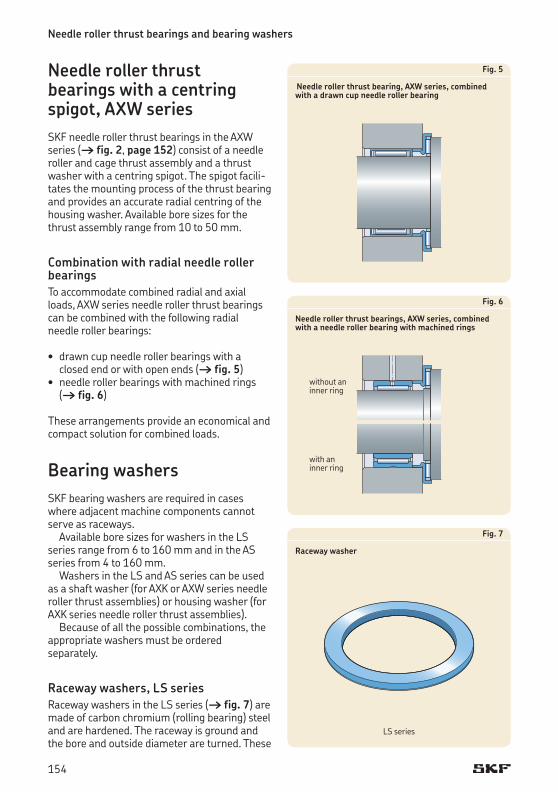
Needle roller thrust bearings and bearing washers
Needle roller thrust bearings with a centring spigot, AXW seriesSKF needle roller thrust bearings in the AXW series († fig. 2, page 152) consist of a needle roller and cage thrust assembly and a thrust washer with a centring spigot. The spigot facili-tates the mounting process of the thrust bearing and provides an accurate radial centring of the housing washer. Available bore sizes for the thrust assembly range from 10 to 50 mm.
Combination with radial needle roller bearingsTo accommodate combined radial and axial loads, AXW series needle roller thrust bearings can be combined with the following radial needle roller bearings:
• drawncupneedlerollerbearingswithaclosed end or with open ends († fig. 5)• needlerollerbearingswithmachinedrings
(† fig. 6)
These arrangements provide an economical and compact solution for combined loads.
Bearing washersSKF bearing washers are required in cases whereadjacentmachinecomponentscannotserve as raceways.
Available bore sizes for washers in the LS series range from 6 to 160 mm and in the AS series from 4 to 160 mm.
Washers in the LS and AS series can be used as a shaft washer (for AXK or AXW series needle roller thrust assemblies) or housing washer (for AXK series needle roller thrust assemblies).
Because of all the possible combinations, the appropriate washers must be ordered separately.
Raceway washers, LS series Raceway washers in the LS series († fig. 7) are made of carbon chromium (rolling bearing) steel and are hardened. The raceway is ground and the bore and outside diameter are turned. These
Fig. 5
Needle roller thrust bearing, AXW series, combined with a drawn cup needle roller bearing
Fig. 6
Needle roller thrust bearings, AXW series, combined with a needle roller bearing with machined rings
Fig. 7
Raceway washer
LS
LS series
without an inner ring
with an inner ring
154
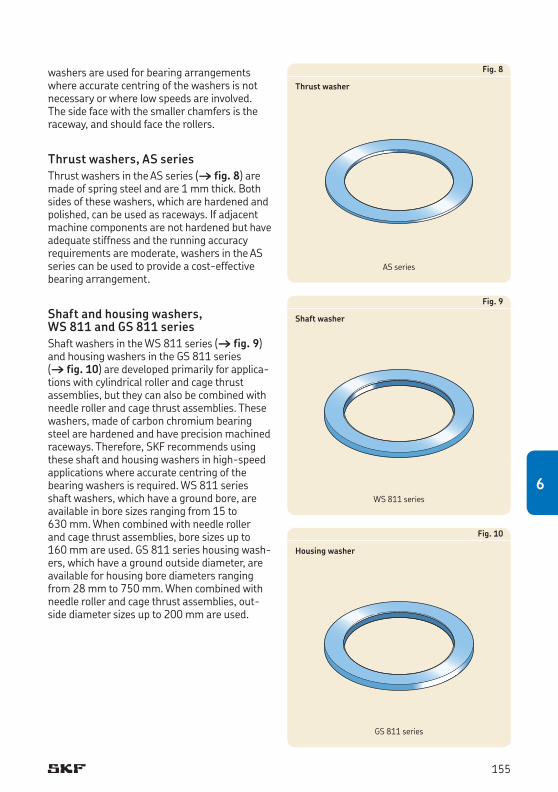
Fig. 8
Thrust washer
AS
Fig. 9
Shaft washer
WS
Fig. 10
Housing washer
GS
washers are used for bearing arrangements where accurate centring of the washers is not necessary or where low speeds are involved. The side face with the smaller chamfers is the raceway, and should face the rollers.
Thrust washers, AS series Thrust washers in the AS series († fig. 8) are made of spring steel and are 1 mm thick. Both sides of these washers, which are hardened and polished,canbeusedasraceways.Ifadjacentmachine components are not hardened but have adequate stiffness and the running accuracy requirements are moderate, washers in the AS series can be used to provide a cost-effective bearing arrangement.
Shaft and housing washers, WS 811 and GS 811 seriesShaft washers in the WS 811 series († fig. 9) and housing washers in the GS 811 series († fig. 10) are developed primarily for applica-tions with cylindrical roller and cage thrust assemblies, but they can also be combined with needle roller and cage thrust assemblies. These washers, made of carbon chromium bearing steel are hardened and have precision machined raceways. Therefore, SKF recommends using these shaft and housing washers in high-speed applications where ac cur ate centring of the bearing washers is required. WS 811 series shaft washers, which have a ground bore, are available in bore sizes ranging from 15 to 630 mm. When combined with needle roller and cage thrust assemblies, bore sizes up to 160 mm are used. GS 811 series housing wash-ers, which have a ground outside diameter, are available for housing bore diameters ranging from 28 mm to 750 mm. When combined with needle roller and cage thrust assemblies, out-side diameter sizes up to 200 mm are used.
AS series
WS 811 series
GS 811 series
155
6
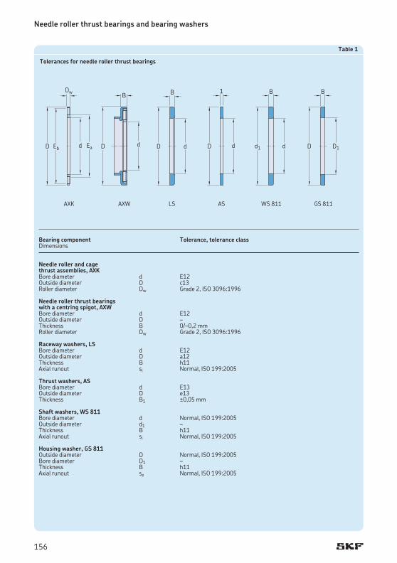
Needle roller thrust bearings and bearing washers
Table 1
Tolerances for needle roller thrust bearings
Bearing component Tolerance, tolerance classDimensions
Needle roller and cage thrust assemblies, AXKBore diameter d E12Outside diameter D c13Roller diameter Dw Grade 2, ISO 3096:1996
Needle roller thrust bearings with a centring spigot, AXWBore diameter d E12Outside diameter D –Thickness B 0/–0,2 mmRoller diameter Dw Grade 2, ISO 3096:1996
Raceway washers, LSBore diameter d E12Outside diameter D a12Thickness B h11Axial runout si Normal, ISO 199:2005
Thrust washers, ASBore diameter d E13Outside diameter D e13Thickness B1 ±0,05 mm
Shaft washers, WS 811Bore diameter d Normal, ISO 199:2005Outside diameter d1 –Thickness B h11Axial runout si Normal, ISO 199:2005
Housing washer, GS 811Outside diameter D Normal, ISO 199:2005Bore diameter D1 –Thickness B h11Axial runout se Normal, ISO 199:2005
d
Dw
EaEbD
AXK
B
dD
AXW
D1
B
D
GS 811
B
dd1
WS 811
d
B
D
LS
d
1
D
AS
156
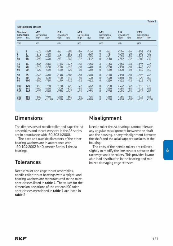
DimensionsThe dimensions of needle roller and cage thrust assemblies and thrust washers in the AS series are in accordance with ISO 3031:2000.
The bore and outside diameters of the other bearing washers are in accordance with ISO 104:2002 for Diameter Series 1 thrust bearings.
TolerancesNeedle roller and cage thrust assemblies, needle roller thrust bearings with a spigot, and bearing washers are manufactured to the toler-ance classes listed in table 1. The values for the dimension deviations of the various ISO toler-ance classes mentioned in table 1 are listed in table 2.
Table 2
ISO tolerance classes
Nominal a12 c13 e13 h11 E12 E13dimension Deviations Deviations Deviations Deviations Deviations Deviationsover incl. high low high low high low high low high low high low
mm μm μm μm μm μm μm
– 3 –270 –370 –60 –200 –14 –154 0 –60 +114 +14 +154 +143 6 –270 –390 –70 –250 –20 –200 0 –75 +140 +20 +200 +206 10 –280 –430 –80 –300 –25 –245 0 –90 +175 +25 +245 +2510 18 –290 –470 –95 –365 –32 –302 0 –110 +212 +32 +302 +32
18 30 –300 –510 –110 –440 –40 –370 0 –130 +250 +40 +370 +4030 40 –310 –560 –120 –510 –50 –440 0 –160 +300 +50 +440 +5040 50 –320 –570 –130 –520 –50 –440 0 –160 +300 +50 +440 +50
50 65 –340 –640 –140 –600 –60 –520 0 –190 +360 +60 +520 +6065 80 –360 –660 –150 –610 –60 –520 0 –190 +360 +60 +520 +6080 100 –380 –730 –170 –710 –72 –612 0 –220 +422 +72 +612 +72
100 120 –410 –760 –180 –720 –72 –612 0 –220 +422 +72 +612 +72120 140 –460 –860 –200 –830 –85 –715 0 –250 +485 +85 +715 +85140 160 –520 –920 –210 –840 –85 –715 0 –250 +485 +85 +715 +85
160 180 –580 –980 –230 –860 –85 –715 0 –250 +485 +85 +715 +85180 200 –660 –1 120 –240 –960 –100 –820 0 –290 +560 +100 +820 +100
MisalignmentNeedle roller thrust bearings cannot tolerate any angular misalignment between the shaft and the housing, or any misalignment between the shaft and the axial support surfaces in the housing.
The ends of the needle rollers are relieved slightly to modify the line contact between the raceways and the rollers. This provides favour-able load distribution in the bearing and min-imizes damaging edge stresses.
157
6
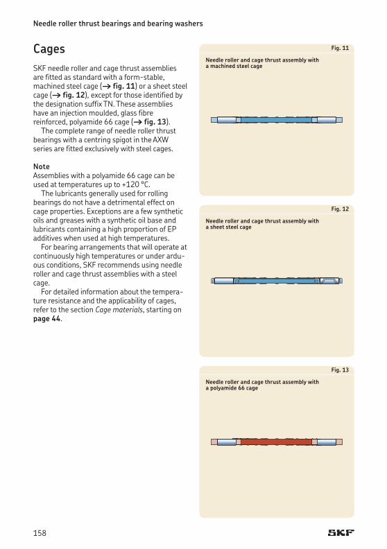
Needle roller thrust bearings and bearing washers
Fig. 11
Needle roller and cage thrust assembly with a machined steel cage
Fig. 12
Needle roller and cage thrust assembly with a sheet steel cage
Fig. 13
Needle roller and cage thrust assembly with a polyamide 66 cage
CagesSKF needle roller and cage thrust assemblies are fitted as standard with a form-stable, machined steel cage († fig. 11) or a sheet steel cage († fig. 12), except for those identified by the designation suffix TN. These assemblies haveaninjectionmoulded,glassfibrere inforced, polyamide 66 cage († fig. 13).
The complete range of needle roller thrust bearings with a centring spigot in the AXW series are fitted exclusively with steel cages.
Note Assemblies with a polyamide 66 cage can be used at temperatures up to +120 °C.
The lubricants generally used for rolling bearings do not have a detrimental effect on cage properties. Exceptions are a few synthetic oils and greases with a synthetic oil base and lubricants containing a high proportion of EP additives when used at high temperatures.
For bearing arrangements that will operate at continuously high temperatures or under ardu-ous conditions, SKF recommends using needle roller and cage thrust assemblies with a steel cage.
For detailed information about the tempera-ture resistance and the applicability of cages, refer to the section Cage materials, starting on page 44.
158
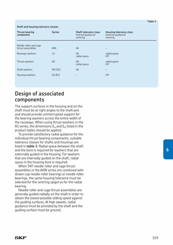
Table 3
Shaft and housing tolerance classes
Thrust bearing Series Shaft tolerance class Housing tolerance classcomponent Internal guidance/ External guidance/ centring centring
Needle roller and cagethrust assemblies AXK h8 –
Raceway washers LS h8 radial space radialspace H9
Thrust washers AS h8 radial space radialspace H9
Shaft washers WS 811 h8 –
Housingwashers GS811 – H9
Design of associated componentsThe support surfaces in the housing and on the shaft must be at right angles to the shaft axis and should provide uninterrupted support for the bearing washers across the entire width of the raceways. When using thrust washers in the AS series, the dimensions Ea and Eb listed in the product tables should be applied.
To provide satisfactory radial guidance for the individual thrust bearing components, suitable tolerance classes for shafts and housings are listed in table 3. Radial space between the shaft and the bore is required for washers that are externally guided in the housing. For washers that are internally guided on the shaft, radial space in the housing bore is required.
When SKF needle roller and cage thrust assemblies in the AXW series are combined with drawn cup needle roller bearings or needle roller bearings, the same housing tolerance must be selected for the centring spigot as for the radial bearing.
Needle roller and cage thrust assemblies are generally guided radially on the shaft in order to obtain the lowest possible sliding speed against the guiding surfaces. At high speeds, radial guidance must be provided by the shaft and the guiding surface must be ground.
159
6
Needle roller thrust bearings and bearing washers
Raceways on a shaft and in a housingFor detailed information about suitable materi-als as well as surface hardness and surface fin-ish, refer to the section Raceways on shafts and in housings, starting on page 50.
Raceways machined on the shaft or in the housing should have the same axial runout as is common for shaft or housing washers. The values for the permissible axial runout for the shaft and housing washers of thrust bearings are listed in table 4.
Supplementary designationsThe designation suffixes used to identify certain features of SKF needle roller thrust bearings are explained in the following.
TN Injectionmouldedcageofglassfibrere inforced polyamide 66
160
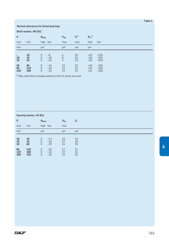
Table 4
Normal tolerances for thrust bearings
Shaft washer, WS 811
d Δdmp Vdp Si1) ΔTs
1)
over incl. high low max max high low
mm μm μm μm μm
– 18 0 –8 6 10 +20 –25018 30 0 –10 8 10 +20 –25030 50 0 –12 9 10 +20 –250
50 80 0 –15 11 10 +20 –30080 120 0 –20 15 15 +25 –300120 180 0 –25 19 15 +25 –400
1) Also valid where raceway washers in the LS series are used
Housing washer, GS 811
D ΔDmp VDp Se
over incl. high low max
mm μm μm μm
18 30 0 –13 10 1030 50 0 –16 12 1050 80 0 –19 14 10 80 120 0 –22 17 15120 180 0 –25 19 15180 250 0 –30 23 20
161
6
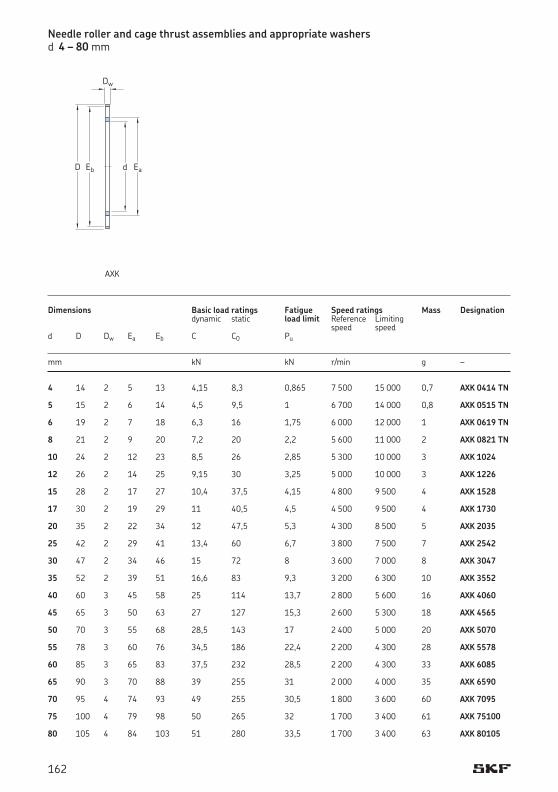
Needle roller and cage thrust assemblies and appropriate washers d 4 – 80 mm
4 14 2 5 13 4,15 8,3 0,865 7 500 15 000 0,7 AXK 0414 TN 5 15 2 6 14 4,5 9,5 1 6 700 14 000 0,8 AXK 0515 TN 6 19 2 7 18 6,3 16 1,75 6 000 12 000 1 AXK 0619 TN 8 21 2 9 20 7,2 20 2,2 5 600 11 000 2 AXK 0821 TN 10 24 2 12 23 8,5 26 2,85 5 300 10 000 3 AXK 1024 12 26 2 14 25 9,15 30 3,25 5 000 10 000 3 AXK 1226 15 28 2 17 27 10,4 37,5 4,15 4 800 9 500 4 AXK 1528 17 30 2 19 29 11 40,5 4,5 4 500 9 500 4 AXK 1730 20 35 2 22 34 12 47,5 5,3 4 300 8 500 5 AXK 2035 25 42 2 29 41 13,4 60 6,7 3 800 7 500 7 AXK 2542 30 47 2 34 46 15 72 8 3 600 7 000 8 AXK 3047 35 52 2 39 51 16,6 83 9,3 3 200 6 300 10 AXK 3552 40 60 3 45 58 25 114 13,7 2 800 5 600 16 AXK 4060 45 65 3 50 63 27 127 15,3 2 600 5 300 18 AXK 4565 50 70 3 55 68 28,5 143 17 2 400 5 000 20 AXK 5070 55 78 3 60 76 34,5 186 22,4 2 200 4 300 28 AXK 5578 60 85 3 65 83 37,5 232 28,5 2 200 4 300 33 AXK 6085 65 90 3 70 88 39 255 31 2 000 4 000 35 AXK 6590 70 95 4 74 93 49 255 30,5 1 800 3 600 60 AXK 7095 75 100 4 79 98 50 265 32 1 700 3 400 61 AXK 75100 80 105 4 84 103 51 280 33,5 1 700 3 400 63 AXK 80105
Dimensions Basic load ratings Fatigue Speed ratings Mass Designation dynamic static load limit Reference Limiting speed speed d D Dw Ea Eb C C0 Pu mm kN kN r/min g –
d
Dw
EaEbD
AXK
162
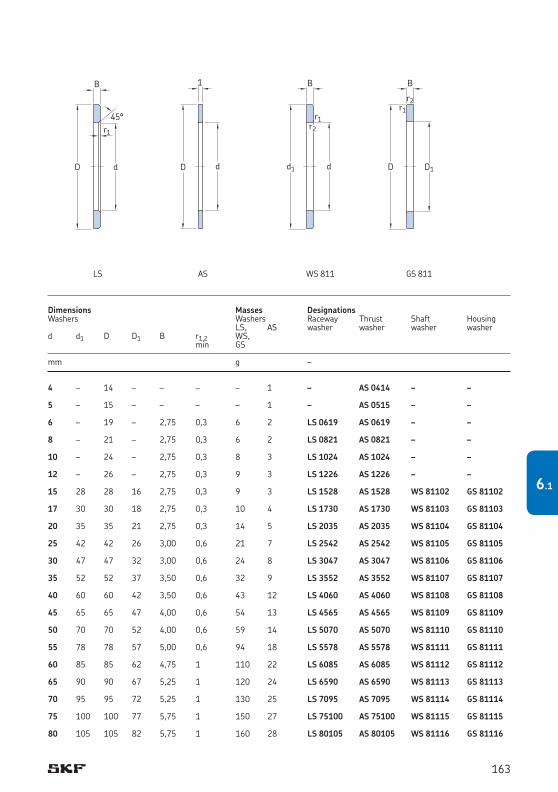
4 – 14 – – – – 1 – AS 0414 – – 5 – 15 – – – – 1 – AS 0515 – – 6 – 19 – 2,75 0,3 6 2 LS 0619 AS 0619 – – 8 – 21 – 2,75 0,3 6 2 LS 0821 AS 0821 – – 10 – 24 – 2,75 0,3 8 3 LS 1024 AS 1024 – – 12 – 26 – 2,75 0,3 9 3 LS 1226 AS 1226 – – 15 28 28 16 2,75 0,3 9 3 LS 1528 AS 1528 WS 81102 GS 81102 17 30 30 18 2,75 0,3 10 4 LS 1730 AS 1730 WS 81103 GS 81103 20 35 35 21 2,75 0,3 14 5 LS 2035 AS 2035 WS 81104 GS 81104 25 42 42 26 3,00 0,6 21 7 LS 2542 AS 2542 WS 81105 GS 81105 30 47 47 32 3,00 0,6 24 8 LS 3047 AS 3047 WS 81106 GS 81106 35 52 52 37 3,50 0,6 32 9 LS 3552 AS 3552 WS 81107 GS 81107 40 60 60 42 3,50 0,6 43 12 LS 4060 AS 4060 WS 81108 GS 81108 45 65 65 47 4,00 0,6 54 13 LS 4565 AS 4565 WS 81109 GS 81109 50 70 70 52 4,00 0,6 59 14 LS 5070 AS 5070 WS 81110 GS 81110 55 78 78 57 5,00 0,6 94 18 LS 5578 AS 5578 WS 81111 GS 81111 60 85 85 62 4,75 1 110 22 LS 6085 AS 6085 WS 81112 GS 81112 65 90 90 67 5,25 1 120 24 LS 6590 AS 6590 WS 81113 GS 81113 70 95 95 72 5,25 1 130 25 LS 7095 AS 7095 WS 81114 GS 81114 75 100 100 77 5,75 1 150 27 LS 75100 AS 75100 WS 81115 GS 81115 80 105 105 82 5,75 1 160 28 LS 80105 AS 80105 WS 81116 GS 81116
Dimensions Masses DesignationsWashers Washers Raceway Thrust Shaft Housing LS, AS washer washer washer washerd d1 D D1 B r1,2 WS, min GS
mm g –
d
B
r1
45°
D
LS
d
1
D
AS
B
d
r2
d1
r1
WS 811
D1
B
D
r1r2
GS 811
163
6.1
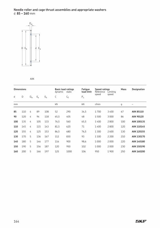
85 110 4 89 108 52 290 34,5 1 700 3 400 67 AXK 85110 90 120 4 94 118 65,5 405 48 1 500 3 000 86 AXK 90120 100 135 4 105 133 76,5 560 65,5 1 400 2 800 100 AXK 100135 110 145 4 115 143 81,5 620 71 1 400 2 800 120 AXK 110145 120 155 4 125 153 86,5 680 76,5 1 300 2 600 130 AXK 120155 130 170 5 136 167 112 830 93 1 100 2 200 210 AXK 130170 140 180 5 146 177 116 900 98,6 1 000 2 000 220 AXK 140180 150 190 5 156 187 120 950 102 1 000 2 000 230 AXK 150190 160 200 5 166 197 125 1000 106 950 1 900 250 AXK 160200
Dimensions Basic load ratings Fatigue Speed ratings Mass Designation dynamic static load limit Reference Limiting speed speed d D Dw Ea Eb C C0 Pu mm kN kN r/min g –
Needle roller and cage thrust assemblies and appropriate washers d 85 – 160 mm
d
Dw
EaEbD
AXK
164
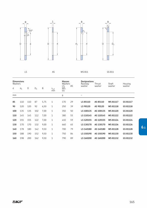
85 110 110 87 5,75 1 170 29 LS 85110 AS 85110 WS 81117 GS 81117 90 120 120 92 6,50 1 250 39 LS 90120 AS 90120 WS 81118 GS 81118 100 135 135 102 7,00 1 350 50 LS 100135 AS 100135 WS 81120 GS 81120 110 145 145 112 7,00 1 380 55 LS 110145 AS 110145 WS 81122 GS 81122 120 155 155 122 7,00 1 410 59 LS 120155 AS 120155 WS 81124 GS 81124 130 170 170 132 9,00 1 660 65 LS 130170 AS 130170 WS 81126 GS 81126 140 178 180 142 9,50 1 700 79 LS 140180 AS 140180 WS 81128 GS 81128 150 188 190 152 9,50 1 750 84 LS 150190 AS 150190 WS 81130 GS 81130 160 198 200 162 9,50 1 790 89 LS 160200 AS 160200 WS 81132 GS 81132
Dimensions Masses DesignationsWashers Washers Raceway Thrust Shaft Housing LS, AS washer washer washer washerd d1 D D1 B r1,2 WS, min GS
mm g –
d
B
r1
45°
D
LS
d
1
D
AS
B
d
r2
d1
r1
WS 811
D1
B
D
r1r2
GS 811
165
6.1
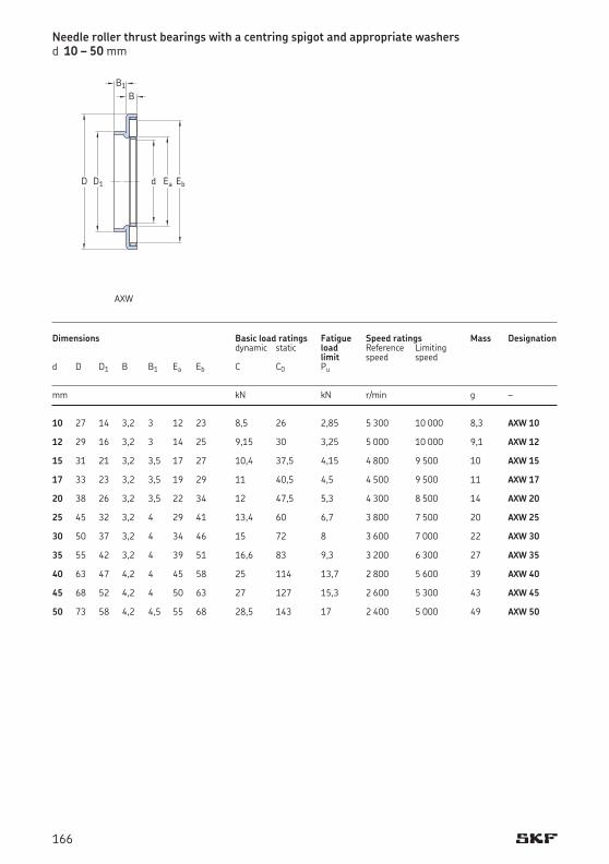
10 27 14 3,2 3 12 23 8,5 26 2,85 5 300 10 000 8,3 AXW 10 12 29 16 3,2 3 14 25 9,15 30 3,25 5 000 10 000 9,1 AXW 12 15 31 21 3,2 3,5 17 27 10,4 37,5 4,15 4 800 9 500 10 AXW 15 17 33 23 3,2 3,5 19 29 11 40,5 4,5 4 500 9 500 11 AXW 17 20 38 26 3,2 3,5 22 34 12 47,5 5,3 4 300 8 500 14 AXW 20 25 45 32 3,2 4 29 41 13,4 60 6,7 3 800 7 500 20 AXW 25 30 50 37 3,2 4 34 46 15 72 8 3 600 7 000 22 AXW 30 35 55 42 3,2 4 39 51 16,6 83 9,3 3 200 6 300 27 AXW 35 40 63 47 4,2 4 45 58 25 114 13,7 2 800 5 600 39 AXW 40 45 68 52 4,2 4 50 63 27 127 15,3 2 600 5 300 43 AXW 45 50 73 58 4,2 4,5 55 68 28,5 143 17 2 400 5 000 49 AXW 50
Dimensions Basic load ratings Fatigue Speed ratings Mass Designation dynamic static load Reference Limiting limit speed speedd D D1 B B1 Ea Eb C C0 Pu
mm kN kN r/min g –
Needle roller thrust bearings with a centring spigot and appropriate washers d 10 – 50 mm
B
dD D1 Ea Eb
B1
AXW
166
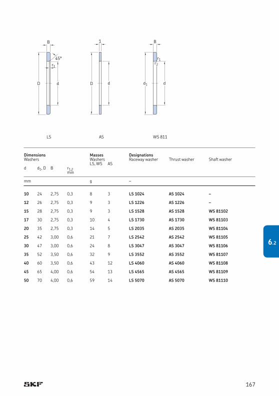
10 24 2,75 0,3 8 3 LS 1024 AS 1024 – 12 26 2,75 0,3 9 3 LS 1226 AS 1226 – 15 28 2,75 0,3 9 3 LS 1528 AS 1528 WS 81102 17 30 2,75 0,3 10 4 LS 1730 AS 1730 WS 81103 20 35 2,75 0,3 14 5 LS 2035 AS 2035 WS 81104 25 42 3,00 0,6 21 7 LS 2542 AS 2542 WS 81105 30 47 3,00 0,6 24 8 LS 3047 AS 3047 WS 81106 35 52 3,50 0,6 32 9 LS 3552 AS 3552 WS 81107 40 60 3,50 0,6 43 12 LS 4060 AS 4060 WS 81108 45 65 4,00 0,6 54 13 LS 4565 AS 4565 WS 81109 50 70 4,00 0,6 59 14 LS 5070 AS 5070 WS 81110
Dimensions Masses DesignationsWashers Washers Raceway washer Thrust washer Shaft washer LS, WS ASd d1, D B r1,2 min
mm g –
d
B
r1
45°
D
LS
d
1
D
AS
B
d
r2
d1
r1
WS 811
167
6.2
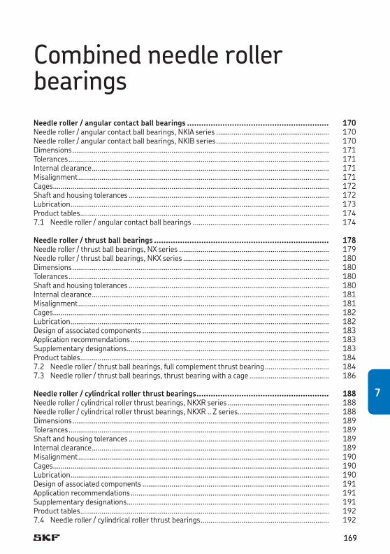
Combined needle roller bearingsNeedle roller / angular contact ball bearings ............................................................ 170Needle roller / angular contact ball bearings, NKIA series .......................................................... 170Needle roller / angular contact ball bearings, NKIB series .......................................................... 170Dimensions .................................................................................................................................... 171Tolerances ...................................................................................................................................... 171Internal clearance .......................................................................................................................... 171Misalignment ................................................................................................................................. 171Cages .............................................................................................................................................. 172Shaft and housing tolerances ....................................................................................................... 172Lubrication ..................................................................................................................................... 173Product tables ................................................................................................................................ 1747.1 Needle roller / angular contact ball bearings ...................................................................... 174
Needle roller / thrust ball bearings .......................................................................... 178Needle roller / thrust ball bearings, NX series ............................................................................. 179Needle roller / thrust ball bearings, NKX series ........................................................................... 180Dimensions .................................................................................................................................... 180Tolerances ...................................................................................................................................... 180Shaft and housing tolerances ....................................................................................................... 180Internal clearance .......................................................................................................................... 181Misalignment ................................................................................................................................. 181Cages .............................................................................................................................................. 182Lubrication ..................................................................................................................................... 182Design of associated components ................................................................................................ 183Application recommendations ...................................................................................................... 183Supplementary designations ........................................................................................................ 183Product tables ................................................................................................................................ 1847.2 Needle roller / thrust ball bearings, full complement thrust bearing ................................. 1847.3 Needle roller / thrust ball bearings, thrust bearing with a cage ......................................... 186
Needle roller / cylindrical roller thrust bearings ........................................................ 188Needle roller / cylindrical roller thrust bearings, NKXR series .................................................... 188Needle roller / cylindrical roller thrust bearings, NKXR .. Z series............................................... 188Dimensions .................................................................................................................................... 189Tolerances ...................................................................................................................................... 189Shaft and housing tolerances ....................................................................................................... 189Internal clearance .......................................................................................................................... 189Misalignment ................................................................................................................................. 190Cages .............................................................................................................................................. 190Lubrication ..................................................................................................................................... 190Design of associated components ................................................................................................ 191Application recommendations ...................................................................................................... 191Supplementary designations ........................................................................................................ 191Product tables ................................................................................................................................ 1927.4 Needle roller / cylindrical roller thrust bearings .................................................................. 192
7
169169
7
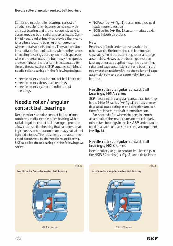
Needle roller / angular contact ball bearings
Combined needle roller bearings consist of a radial needle roller bearing combined with a thrust bearing and are consequently able to accommodate both radial and axial loads. Com-bined needle roller bearings provide the means to produce locating bearing arrangements where radial space is limited. They are particu-larly suitable for applications where other types of locating bearings occupy too much space, or where the axial loads are too heavy, the speeds are too high, or the lubricant is inadequate for simple thrust washers. SKF supplies combined needle roller bearings in the following designs:
• needleroller/angularcontactballbearings• needleroller/thrustballbearings• needleroller/cylindricalrollerthrust
bearings
Needle roller / angular contact ball bearingsNeedle roller / angular contact ball bearings combine a radial needle roller bearing with a radial angular contact ball bearing to produce a low cross section bearing that can operate at high speeds and accommodate heavy radial and light axial loads. The radial loads are accommo-dated exclusively by the needle roller bearing. SKF supplies these bearings in the following two series:
Fig. 1
Needle roller / angular contact ball bearing
Fig. 2
Needle roller / angular contact ball bearing
• NKIAseries(† fig. 1), accommodates axial loads in one direction• NKIBseries(† fig. 2), accommodates axial
loads in both directions
NoteBearings of both series are separable. In other words, the inner ring can be mounted separately from the outer ring, roller and cage assemblies.However,thebearingsmustbe kept together as supplied – e.g. the outer ring, roller and cage assembly from one bearing are not interchangeable with the the roller and cage assembly from another seemingly identical bearing.
Needle roller / angular contact ball bearings, NKIA seriesSKF needle roller / angular contact ball bearings in the NKIA 59 series († fig. 1) can accommo-date axial loads acting in one direction and can therefore locate the shaft in one direction.
For short shafts, where changes in length as a result of thermal expansion are relatively minor, two bearings in the NKIA 59 series can be used in a back-to-back (mirrored) arrangement († fig. 3).
Needle roller / angular contact ball bearings, NKIB seriesNeedle roller / angular contact ball bearings in the NKIB 59 series († fig. 2) are able to locate
NKIA 59 series NKIB 59 series
170
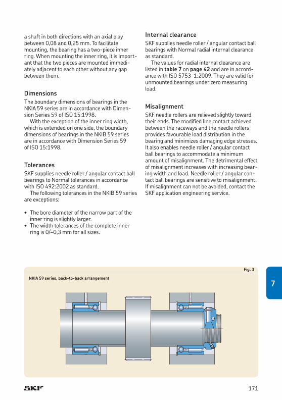
a shaft in both directions with an axial play between 0,08 and 0,25 mm. To facilitate mounting, the bearing has a two-piece inner ring. When mounting the inner ring, it is import-ant that the two pieces are mounted immedi-atelyadjacenttoeachotherwithoutanygapbetween them.
DimensionsThe boundary dimensions of bearings in the NKIA 59 series are in accordance with Dimen-sion Series 59 of ISO 15:1998.
With the exception of the inner ring width, which is extended on one side, the boundary dimensions of bearings in the NKIB 59 series are in accordance with Dimension Series 59 of ISO 15:1998.
TolerancesSKF supplies needle roller / angular contact ball bearings to Normal tolerances in accordance with ISO 492:2002 as standard.
The following tolerances in the NKIB 59 series are exceptions:
• Theborediameterofthenarrowpartoftheinner ring is slightly larger.• Thewidthtolerancesofthecompleteinner
ring is 0/–0,3 mm for all sizes.
Fig. 3
NKIA 59 series, back-to-back arrangement
Internal clearanceSKF supplies needle roller / angular contact ball bearings with Normal radial internal clearance as standard.
The values for radial internal clearance are listed in table 7 on page 42 and are in accord-ance with ISO 5753-1:2009. They are valid for unmounted bearings under zero measuring load.
MisalignmentSKF needle rollers are relieved slightly toward their ends. The modified line contact achieved between the raceways and the needle rollers provides favourable load distribution in the bearing and minimizes damaging edge stresses. It also enables needle roller / angular contact ball bearings to accommodate a minimum amount of misalignment. The detrimental effect of misalignment increases with increasing bear-ing width and load. Needle roller / angular con-tact ball bearings are sensitive to misalignment. If misalignment can not be avoided, contact the SKF application engineering service.
171
7
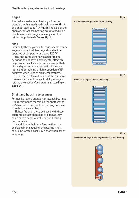
Needle roller / angular contact ball bearings
CagesThe radial needle roller bearing is fitted as standard with a machined steel cage († fig. 4) or a sheet steel cage († fig. 5). The balls of the angular contact ball bearing are retained in an injectionmouldedcagemadeofglassfibrere inforced polyamide 66 († fig. 6).
NoteLimited by the polyamide 66 cage, needle roller / angular contact ball bearings should not be operated at temperatures above 120 °C.
The lubricants generally used for rolling bearings do not have a detrimental effect on cage properties. Exceptions are a few synthetic oils and greases with a synthetic oil base and lubricants containing a high proportion of EP additives when used at high temperatures.
For detailed information about the tempera-ture resistance and the applicability of cages, refer to the section Cage materials, starting on page 44.
Shaft and housing tolerancesFor needle roller / angular contact ball bearings SKF recommends machining the shaft seat to a k5 tolerance class, and the housing bore seat to an M6 tolerance class.
Tighter fits than those achieved with these tolerance classes should be avoided as they could have a negative influence on bearing performance.
In addition to their interference fit on the shaft and in the housing, the bearing rings should be located axially by a shaft shoulder or snap ring.
Fig. 4
Machined steel cage of the radial bearing
Fig. 5
Sheet steel cage of the radial bearing
Fig. 6
Polyamide 66 cage of the angular contact ball bearing
172
Lubrication To facilitate efficient lubrication, the needle roller bearing has an annular groove with one lubrication hole in the outer ring. Depending on the application, needle roller / angular contact ball bearings can be grease or oil lubricated. In the case of grease lubrication, both the needle roller bearing and ball bearing should be filled with the same lubricant. If grease lubrication is going to be used, the bearing should be lubri-cated before mounting.
Relubrication intervals for the needle roller and angular contact ball bearing must be calcu-lated separately. The lower of the two intervals should be used.
For additional information about lubrication, refer to the section Lubrication, starting on page 52.
173
7
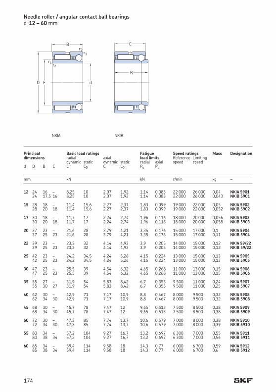
Needle roller / angular contact ball bearingsd 12 – 60 mm
12 24 16 – 8,25 10 2,07 1,92 1,14 0,083 22 000 26 000 0,04 NKIA 5901 24 17,5 16 8,25 10 2,07 1,92 1,14 0,083 22 000 26 000 0,043 NKIB 5901 15 28 18 – 11,4 15,6 2,27 2,37 1,83 0,099 19 000 22 000 0,05 NKIA 5902 28 20 18 11,4 15,6 2,27 2,37 1,83 0,099 19 000 22 000 0,052 NKIB 5902 17 30 18 – 11,7 17 2,24 2,74 1,96 0,116 18 000 20 000 0,056 NKIA 5903 30 20 18 11,7 17 2,24 2,74 1,96 0,116 18 000 20 000 0,058 NKIB 5903 20 37 23 – 21,6 28 3,79 4,21 3,35 0,176 15 000 17 000 0,1 NKIA 5904 37 25 23 21,6 28 3,79 4,21 3,35 0,176 15 000 17 000 0,11 NKIB 5904 22 39 23 – 23,3 32 4,14 4,93 3,9 0,205 14 000 15 000 0,12 NKIA 59/22 39 25 23 23,3 32 4,14 4,93 3,9 0,205 14 000 15 000 0,12 NKIB 59/22 25 42 23 – 24,2 34,5 4,24 5,26 4,15 0,224 13 000 15 000 0,13 NKIA 5905 42 25 23 24,2 34,5 4,24 5,26 4,15 0,224 13 000 15 000 0,13 NKIB 5905 30 47 23 – 25,5 39 4,54 6,32 4,65 0,268 11 000 13 000 0,15 NKIA 5906 47 25 23 25,5 39 4,54 6,32 4,65 0,268 11 000 13 000 0,15 NKIB 5906 35 55 27 – 31,9 54 5,83 8,42 6,7 0,355 9 500 11 000 0,24 NKIA 5907 55 30 27 31,9 54 5,83 8,42 6,7 0,355 9 500 11 000 0,25 NKIB 5907 40 62 30 – 42,9 71 7,17 10,9 8,8 0,467 8 000 9 500 0,32 NKIA 5908 62 34 30 42,9 71 7,17 10,9 8,8 0,467 8 000 9 500 0,32 NKIB 5908 45 68 30 – 45,7 78 7,47 12 9,65 0,513 7 500 8 500 0,38 NKIA 5909 68 34 30 45,7 78 7,47 12 9,65 0,513 7 500 8 500 0,38 NKIB 5909 50 72 30 – 47,3 85 7,74 13,7 10,6 0,579 7 000 8 000 0,38 NKIA 5910 72 34 30 47,3 85 7,74 13,7 10,6 0,579 7 000 8 000 0,39 NKIB 5910 55 80 34 – 57,2 104 9,27 16,7 13,2 0,697 6 300 7 000 0,55 NKIA 5911 80 38 34 57,2 104 9,27 16,7 13,2 0,697 6 300 7 000 0,56 NKIB 5911 60 85 34 – 59,4 114 9,58 18 14,3 0,77 6 000 6 700 0,59 NKIA 5912 85 38 34 59,4 114 9,58 18 14,3 0,77 6 000 6 700 0,6 NKIB 5912
Principal Basic load ratings Fatigue Speed ratings Mass Designationdimensions radial axial load limits Reference Limiting dynamic static dynamic static radial axial speed speedd D B C C C0 C C0 Pu Pu mm kN kN r/min kg –
d
B
r1
r1
F
r2
r2
D
C
B
NKIA NKIB
174
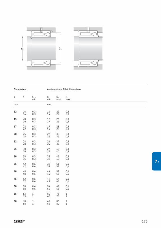
12 16 0,3 14 22 0,3 16 0,3 14 22 0,3 15 20 0,3 17 26 0,3 20 0,3 17 26 0,3 17 22 0,3 19 28 0,3 22 0,3 19 28 0,3 20 25 0,3 22 35 0,3 25 0,3 22 35 0,3 22 28 0,3 24 37 0,3 28 0,3 24 37 0,3 25 30 0,3 27 40 0,3 30 0,3 27 40 0,3 30 35 0,3 32 45 0,3 35 0,3 32 45 0,3 35 42 0,6 39 51 0,6 42 0,6 39 51 0,6 40 48 0,6 44 58 0,6 48 0,6 44 58 0,6 45 52 0,6 49 64 0,6 52 0,6 49 64 0,6 50 58 0,6 54 68 0,6 58 0,6 54 68 0,6 55 63 1 60 75 1 63 1 60 75 1 60 68 1 65 80 1 68 1 65 80 1
Dimensions Abutment and fillet dimensions
d F r1,2 da Da ra min min max max mm mm
Dada
ra
ra
175
7.1
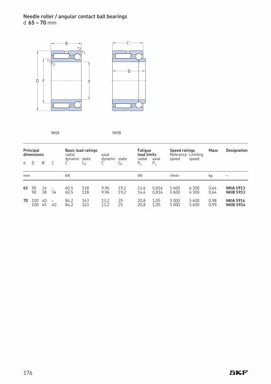
65 90 34 – 60,5 118 9,96 19,2 14,6 0,816 5 600 6 300 0,64 NKIA 5913 90 38 34 60,5 118 9,96 19,2 14,6 0,816 5 600 6 300 0,64 NKIB 5913 70 100 40 – 84,2 163 13,2 25 20,8 1,05 5 000 5 600 0,98 NKIA 5914 100 45 40 84,2 163 13,2 25 20,8 1,05 5 000 5 600 0,99 NKIB 5914
Needle roller / angular contact ball bearingsd 65 – 70 mm
Principal Basic load ratings Fatigue Speed ratings Mass Designationdimensions radial axial load limits Reference Limiting dynamic static dynamic static radial axial speed speed d D B C C C0 C C0 Pu Pu mm kN kN r/min kg –
d
B
r1
r1
F
r2
r2
D
C
B
NKIA NKIB
176
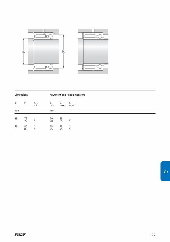
65 72 1 70 85 1 72 1 70 85 1 70 80 1 75 95 1 80 1 75 95 1
Dimensions Abutment and fillet dimensions
d F r1,2 da Da ra min min max max mm mm
Dada
ra
ra
177
7.1
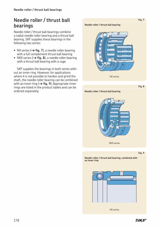
Needle roller / thrust ball bearings
Needle roller / thrust ball bearingsNeedle roller / thrust ball bearings combine a radial needle roller bearing and a thrust ball bearing. SKF supplies these bearings in the following two series:
• NX series († fig. 7), a needle roller bearing with a full complement thrust ball bearing • NKX series († fig. 8), a needle roller bearing
with a thrust ball bearing with a cage
SKF supplies the bearings in both series with-outaninnerring.However,forapplicationswhere it is not possible to harden and grind the shaft, the needle roller bearing can be combined with an inner ring († fig. 9). Appropriate inner rings are listed in the product tables and can be ordered separately.
Fig. 7
Needle roller / thrust ball bearing
Fig. 8
Needle roller / thrust ball bearing
Fig. 9
Needle roller / thrust ball bearing, combined with an inner ring
NX series
NKX series
NX series
178
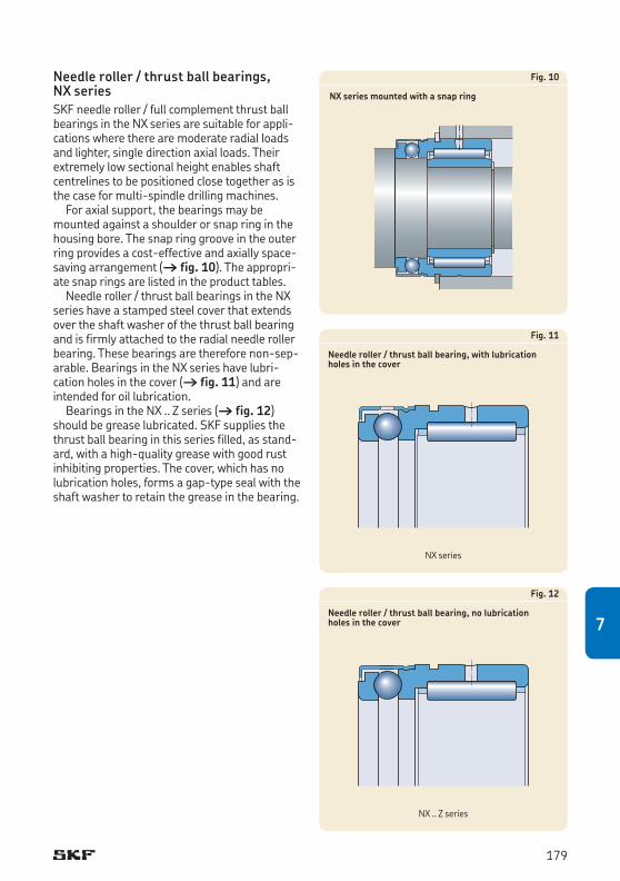
Needle roller / thrust ball bearings, NX series SKF needle roller / full complement thrust ball bearings in the NX series are suitable for appli-cations where there are moderate radial loads and lighter, single direction axial loads. Their extremely low sectional height enables shaft centrelines to be positioned close together as is the case for multi-spindle drilling machines.
For axial support, the bearings may be mounted against a shoulder or snap ring in the housing bore. The snap ring groove in the outer ring provides a cost-effective and axially space-saving arrangement († fig. 10). The appropri-ate snap rings are listed in the product tables.
Needle roller / thrust ball bearings in the NX series have a stamped steel cover that extends over the shaft washer of the thrust ball bearing and is firmly attached to the radial needle roller bearing. These bearings are therefore non-sep-arable. Bearings in the NX series have lubri-cation holes in the cover († fig. 11) and are intended for oil lubrication.
Bearings in the NX .. Z series († fig. 12) should be grease lubricated. SKF supplies the thrust ball bearing in this series filled, as stand-ard, with a high-quality grease with good rust inhibiting properties. The cover, which has no lubrication holes, forms a gap-type seal with the shaft washer to retain the grease in the bearing.
Fig. 10
NX series mounted with a snap ring
Fig. 11
Needle roller / thrust ball bearing, with lubrication holes in the cover
Fig. 12
Needle roller / thrust ball bearing, no lubrication holes in the cover
NX series
NX .. Z series
179
7
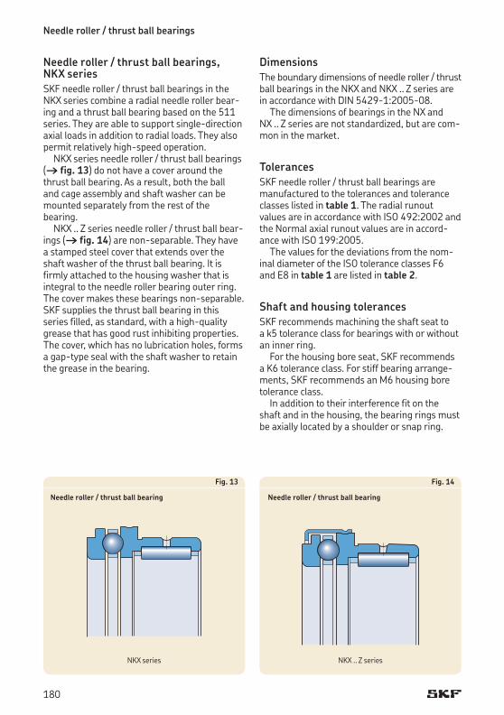
Needle roller / thrust ball bearings
Needle roller / thrust ball bearings, NKX series SKF needle roller / thrust ball bearings in the NKX series combine a radial needle roller bear-ing and a thrust ball bearing based on the 511 series. They are able to support single-direction axial loads in addition to radial loads. They also permit relatively high-speed operation.
NKX series needle roller / thrust ball bearings († fig. 13) do not have a cover around the thrust ball bearing. As a result, both the ball and cage assembly and shaft washer can be mounted separately from the rest of the bearing.
NKX .. Z series needle roller / thrust ball bear-ings († fig. 14) are non-separable. They have a stamped steel cover that extends over the shaft washer of the thrust ball bearing. It is firmly attached to the housing washer that is integral to the needle roller bearing outer ring. The cover makes these bearings non-separable. SKF supplies the thrust ball bearing in this series filled, as standard, with a high-quality grease that has good rust inhibiting properties. The cover, which has no lubrication holes, forms a gap-type seal with the shaft washer to retain the grease in the bearing.
Fig. 13
Needle roller / thrust ball bearing
Fig. 14
Needle roller / thrust ball bearing
DimensionsThe boundary dimensions of needle roller / thrust ball bearings in the NKX and NKX .. Z series are in accordance with DIN 5429-1:2005-08.
The dimensions of bearings in the NX and NX .. Z series are not standardized, but are com-mon in the market.
TolerancesSKF needle roller / thrust ball bearings are manu factured to the tolerances and tolerance classes listed in table 1. The radial runout val ues are in accordance with ISO 492:2002 and the Normal axial runout values are in accord-ance with ISO 199:2005.
The values for the devi ations from the nom-inal diameter of the ISO tolera nce classes F6 and E8 in table 1 are listed in table 2.
Shaft and housing tolerancesSKF recommends machining the shaft seat to a k5 tolerance class for bearings with or without an inner ring.
For the housing bore seat, SKF recommends a K6 tolerance class. For stiff bearing arrange-ments, SKF recommends an M6 housing bore tolerance class.
In addition to their interference fit on the shaft and in the housing, the bearing rings must be axially located by a shoulder or snap ring.
NKX series NKX .. Z series
180
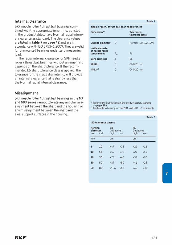
Table 1
Needle roller / thrust ball bearing tolerances
Dimension1) Tolerance, tolerance class
Outside diameter D Normal, ISO 492:1994
Inside diameter of needle roller complement Fw F6
Bore diameter d E8
Width C 0/–0,25 mm
Width2) C1 0/–0,20 mm
Table 2
ISO tolerance classes
Nominal E8 F6diameter Deviations Deviationsover incl. high low high low
mm μm μm
6 10 +47 +25 +22 +13
10 18 +59 +32 +27 +16
18 30 +73 +40 +33 +20
30 50 +89 +50 +41 +25
50 80 +106 +60 +49 +30
1) Refer to the illustrations in the product tables, starting on page 184.
2) Applicable to bearings in the NKX and NKX .. Z series only
Internal clearanceSKF needle roller / thrust ball bearings com-bined with the appropriate inner ring, as listed in the product tables, have Normal radial intern-al clearance as standard. The clearance values are listed in table 7 on page 42 and are in accordance with ISO 5753-1:2009. They are valid for unmounted bearings under zero measuring load.
The radial internal clearance for SKF needle roller / thrust ball bearings without an inner ring depends on the shaft tolerance. If the recom-mended k5 shaft tolerance class is applied, the tolerance for the inside diameter Fw will provide an internal clearance that is slightly less than the Normal radial internal clearance.
MisalignmentSKF needle roller / thrust ball bearings in the NX and NKX series cannot tolerate any angular mis-alignment between the shaft and the housing or any misalignment between the shaft and the axial support surfaces in the housing.
181
7
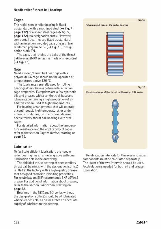
Needle roller / thrust ball bearings
CagesThe radial needle roller bearing is fitted as standard with a machined steel († fig. 4, page 172) or a sheet steel cage († fig. 5, page 172),nodesignationsuffix.However,some small bearings are fitted as standard withaninjectionmouldedcageofglassfibrereinforced polyamide 66 († fig. 15), desig-nation suffix TN.
The cage, that retains the balls of the thrust ball bearing (NKX series), is made of sheet steel († fig. 16).
NoteNeedle roller / thrust ball bearings with a poly amide 66 cage should not be operated at temperatures above 120 °C.
The lubricants generally used for rolling bearings do not have a detrimental effect on cage properties. Exceptions are a few synthetic oils and greases with a synthetic oil base and lubricants containing a high proportion of EP additives when used at high temperatures.
For bearing arrangements that will operate at continuously high temperatures or under arduous conditions, SKF recommends using needle roller / thrust ball bearings with steel cages.
For detailed information about the tempera-ture resistance and the applicability of cages, refer to the section Cage materials, starting on page 44.
Lubrication To facilitate efficient lubrication, the needle roller bearing has an annular groove with one lubrication hole in the outer ring.
The shielded thrust bearing of needle roller / thrust ball bearings with the designation suffix Z is filled at the factory with a high-quality grease that has good corrosion inhibiting properties. For relubrication, SKF recommends SKF LGWA 2 grease. For additional information about greases, refer to the section Lubrication, starting on page 52.
Bearings in the NKX and NX series without the designation suffix Z should be oil lubricated whenever possible, as oil facilitates an adequate supply of lubricant to the bearing.
Fig. 15
Polyamide 66 cage of the radial bearing
Fig. 16
Sheet steel cage of the thrust ball bearing, NKX series
Relubrication intervals for the axial and radial components must be calculated separately. The lower of the two intervals should be used. A calculation is needed for both oil and grease lubrication.
182
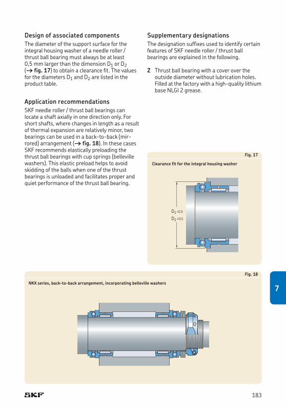
Design of associated componentsThe diameter of the support surface for the integral housing washer of a needle roller / thrust ball bearing must always be at least 0,5 mm larger than the dimension D1 or D2 († fig. 17) to obtain a clearance fit. The values for the diameters D1 and D2 are listed in the product table.
Application recommendationsSKF needle roller / thrust ball bearings can locate a shaft axially in one direction only. For short shafts, where changes in length as a result of thermal expansion are relatively minor, two bearings can be used in a back-to-back (mir-rored) arrangement († fig. 18). In these cases SKF recommends elastically preloading the thrust ball bearings with cup springs (belle ville washers). This elastic preload helps to avoid skidding of the balls when one of the thrust bearings is unloaded and facilitates proper and quiet performance of the thrust ball bearing.
Fig. 17
Clearance fit for the integral housing washer
D1D2
+0,5
+0,5
Fig. 18
NKX series, back-to-back arrangement, incorporating belleville washers
Supplementary designationsThe designation suffixes used to identify certain features of SKF needle roller / thrust ball bearings are explained in the following.
Z Thrust ball bearing with a cover over the outside diameter without lubrication holes. Filled at the factory with a high-quality lithium base NLGI 2 grease.
183
7
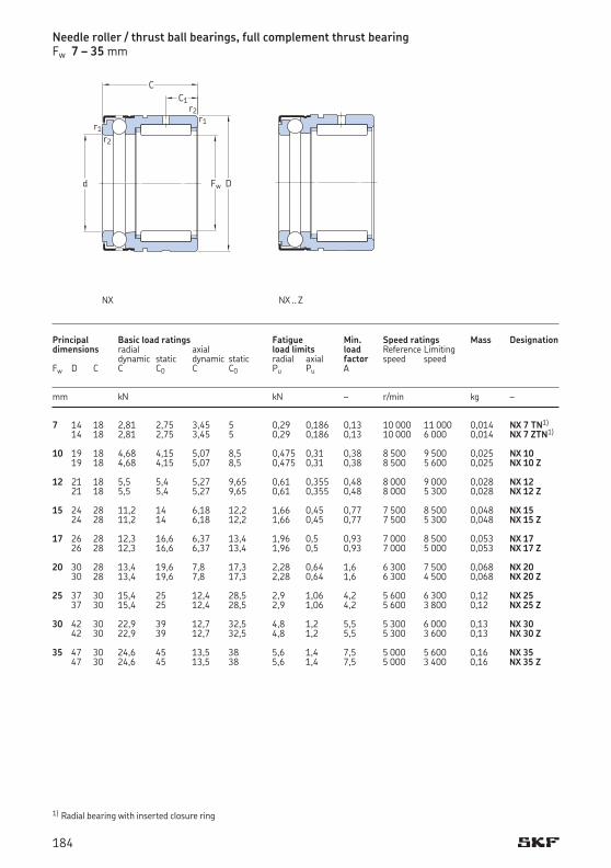
Needle roller / thrust ball bearings, full complement thrust bearingFw 7 – 35 mm
7 14 18 2,81 2,75 3,45 5 0,29 0,186 0,13 10 000 11 000 0,014 NX 7 TN1)
14 18 2,81 2,75 3,45 5 0,29 0,186 0,13 10 000 6 000 0,014 NX 7 ZTN1)
10 19 18 4,68 4,15 5,07 8,5 0,475 0,31 0,38 8 500 9 500 0,025 NX 10 19 18 4,68 4,15 5,07 8,5 0,475 0,31 0,38 8 500 5 600 0,025 NX 10 Z 12 21 18 5,5 5,4 5,27 9,65 0,61 0,355 0,48 8 000 9 000 0,028 NX 12 21 18 5,5 5,4 5,27 9,65 0,61 0,355 0,48 8 000 5 300 0,028 NX 12 Z 15 24 28 11,2 14 6,18 12,2 1,66 0,45 0,77 7 500 8 500 0,048 NX 15 24 28 11,2 14 6,18 12,2 1,66 0,45 0,77 7 500 5 300 0,048 NX 15 Z 17 26 28 12,3 16,6 6,37 13,4 1,96 0,5 0,93 7 000 8 500 0,053 NX 17 26 28 12,3 16,6 6,37 13,4 1,96 0,5 0,93 7 000 5 000 0,053 NX 17 Z 20 30 28 13,4 19,6 7,8 17,3 2,28 0,64 1,6 6 300 7 500 0,068 NX 20 30 28 13,4 19,6 7,8 17,3 2,28 0,64 1,6 6 300 4 500 0,068 NX 20 Z 25 37 30 15,4 25 12,4 28,5 2,9 1,06 4,2 5 600 6 300 0,12 NX 25 37 30 15,4 25 12,4 28,5 2,9 1,06 4,2 5 600 3 800 0,12 NX 25 Z 30 42 30 22,9 39 12,7 32,5 4,8 1,2 5,5 5 300 6 000 0,13 NX 30 42 30 22,9 39 12,7 32,5 4,8 1,2 5,5 5 300 3 600 0,13 NX 30 Z 35 47 30 24,6 45 13,5 38 5,6 1,4 7,5 5 000 5 600 0,16 NX 35 47 30 24,6 45 13,5 38 5,6 1,4 7,5 5 000 3 400 0,16 NX 35 Z
Principal Basic load ratings Fatigue Min. Speed ratings Mass Designationdimensions radial axial load limits load Reference Limiting dynamic static dynamic static radial axial factor speed speed Fw D C C C0 C C0 Pu Pu A mm kN kN – r/min kg –
1) Radial bearing with inserted closure ring
Fw
C1C
r1
D
r1
r2
r2
d
NX NX .. Z
184
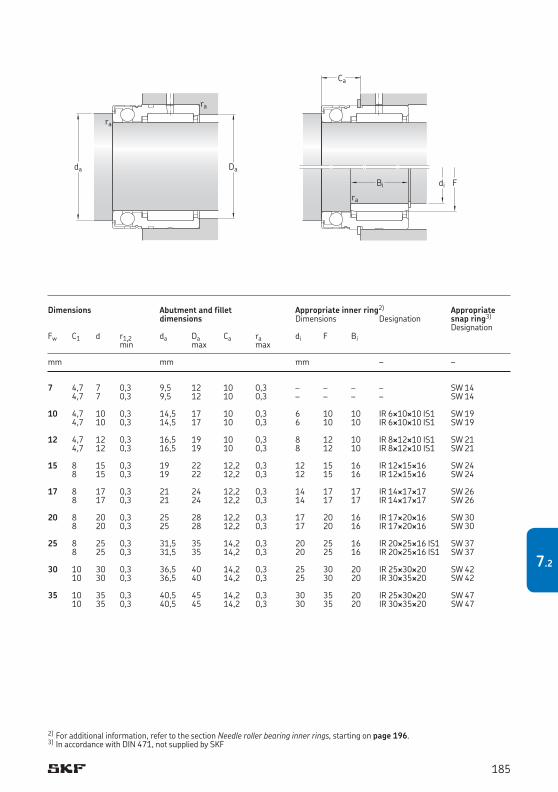
7 4,7 7 0,3 9,5 12 10 0,3 – – – – SW 14 4,7 7 0,3 9,5 12 10 0,3 – – – – SW 14 10 4,7 10 0,3 14,5 17 10 0,3 6 10 10 IR 6¥10¥10 IS1 SW 19 4,7 10 0,3 14,5 17 10 0,3 6 10 10 IR 6¥10¥10 IS1 SW 19 12 4,7 12 0,3 16,5 19 10 0,3 8 12 10 IR 8¥12¥10 IS1 SW 21 4,7 12 0,3 16,5 19 10 0,3 8 12 10 IR 8¥12¥10 IS1 SW 21 15 8 15 0,3 19 22 12,2 0,3 12 15 16 IR 12¥15¥16 SW 24 8 15 0,3 19 22 12,2 0,3 12 15 16 IR 12¥15¥16 SW 24 17 8 17 0,3 21 24 12,2 0,3 14 17 17 IR 14¥17¥17 SW 26 8 17 0,3 21 24 12,2 0,3 14 17 17 IR 14¥17¥17 SW 26 20 8 20 0,3 25 28 12,2 0,3 17 20 16 IR 17¥20¥16 SW 30 8 20 0,3 25 28 12,2 0,3 17 20 16 IR 17¥20¥16 SW 30 25 8 25 0,3 31,5 35 14,2 0,3 20 25 16 IR 20¥25¥16 IS1 SW 37 8 25 0,3 31,5 35 14,2 0,3 20 25 16 IR 20¥25¥16 IS1 SW 37 30 10 30 0,3 36,5 40 14,2 0,3 25 30 20 IR 25¥30¥20 SW 42 10 30 0,3 36,5 40 14,2 0,3 25 30 20 IR 30¥35¥20 SW 42 35 10 35 0,3 40,5 45 14,2 0,3 30 35 20 IR 25¥30¥20 SW 47 10 35 0,3 40,5 45 14,2 0,3 30 35 20 IR 30¥35¥20 SW 47
Dimensions Abutment and fillet Appropriate inner ring2) Appropriate dimensions Dimensions Designation snap ring3)
DesignationFw C1 d r1,2 da Da Ca ra di F Bi min max max
mm mm mm – –
2) For additional information, refer to the section Needle roller bearing inner rings, starting on page 196.3) In accordance with DIN 471, not supplied by SKF
Dada
ra
ra
di
Ca
FBi
ra
185
7.2
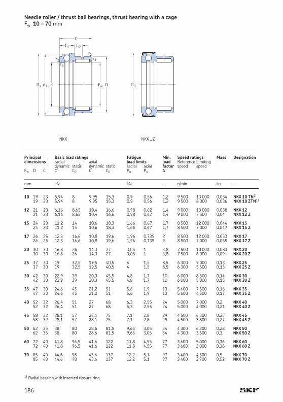
Needle roller / thrust ball bearings, thrust bearing with a cageFw 10 – 70 mm
10 19 23 5,94 8 9,95 15,3 0,9 0,56 1,2 9 500 13 000 0,034 NKX 10 TN1)
19 23 5,94 8 9,95 15,3 0,9 0,56 1,2 9 500 8 000 0,036 NKX 10 ZTN1)
12 21 23 6,16 8,65 10,4 16,6 0,98 0,62 1,4 9 000 13 000 0,038 NKX 12 21 23 6,16 8,65 10,4 16,6 0,98 0,62 1,4 9 000 7 500 0,04 NKX 12 Z 15 24 23 11,2 14 10,6 18,3 1,66 0,67 1,7 8 500 12 000 0,044 NKX 15 24 23 11,2 14 10,6 18,3 1,66 0,67 1,7 8 500 7 000 0,047 NKX 15 Z 17 26 25 12,3 16,6 10,8 19,6 1,96 0,735 2 8 500 12 000 0,053 NKX 17 26 25 12,3 16,6 10,8 19,6 1,96 0,735 2 8 500 7 000 0,055 NKX 17 Z 20 30 30 16,8 26 14,3 27 3,05 1 3,8 7 500 10 000 0,083 NKX 20 30 30 16,8 26 14,3 27 3,05 1 3,8 7 500 6 000 0,09 NKX 20 Z 25 37 30 19 32,5 19,5 40,5 4 1,5 8,5 6 300 9 000 0,13 NKX 25 37 30 19 32,5 19,5 40,5 4 1,5 8,5 6 300 5 500 0,13 NKX 25 Z 30 42 30 22,9 39 20,3 45,5 4,8 1,7 10 6 000 8 500 0,14 NKX 30 42 30 22,9 39 20,3 45,5 4,8 1,7 10 6 000 5 000 0,15 NKX 30 Z 35 47 30 24,6 45 21,2 51 5,6 1,9 13 5 600 7 500 0,16 NKX 35 47 30 24,6 45 21,2 51 5,6 1,9 13 5 600 4 500 0,17 NKX 35 Z 40 52 32 26,4 51 27 68 6,3 2,55 24 5 000 7 000 0,2 NKX 40 52 32 26,4 51 27 68 6,3 2,55 24 5 000 4 000 0,21 NKX 40 Z 45 58 32 28,1 57 28,1 75 7,1 2,8 29 4 500 6 300 0,25 NKX 45 58 32 28,1 57 28,1 75 7,1 2,8 29 4 500 3 800 0,27 NKX 45 Z 50 62 35 38 80 28,6 81,5 9,65 3,05 34 4 300 6 300 0,28 NKX 50 62 35 38 80 28,6 81,5 9,65 3,05 34 4 300 3 600 0,3 NKX 50 Z 60 72 40 41,8 96,5 41,6 122 11,8 4,55 77 3 600 5 000 0,36 NKX 60 72 40 41,8 96,5 41,6 122 11,8 4,55 77 3 600 3 000 0,38 NKX 60 Z 70 85 40 44,6 98 43,6 137 12,2 5,1 97 3 400 4 500 0,5 NKX 70 85 40 44,6 98 43,6 137 12,2 5,1 97 3 400 2 700 0,52 NKX 70 Z
Principal Basic load ratings Fatigue Min. Speed ratings Mass Designationdimensions radial axial load limits load Reference Limiting dynamic static dynamic static radial axial factor speed speed Fw D C C C0 C C0 Pu Pu A mm kN kN – r/min kg –
1) Radial bearing with inserted closure ring
Fw
C1 C2
C
r1
Dd
r2
r2r1
d1D1 D2
NKX NKX .. Z
186
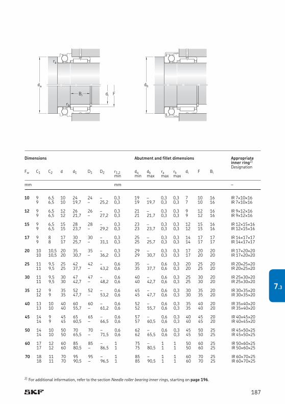
2) For additional information, refer to the section Needle roller bearing inner rings, starting on page 196.
10 9 6,5 10 24 24 – 0,3 19 – 0,3 0,3 7 10 16 IR 7¥10¥16 9 6,5 10 19,7 – 25,2 0,3 19 19,7 0,3 0,3 7 10 16 IR 7¥10¥16 12 9 6,5 12 26 26 – 0,3 21 – 0,3 0,3 9 12 16 IR 9¥12¥16 9 6,5 12 21,7 – 27,2 0,3 21 21,7 0,3 0,3 9 12 16 IR 9¥12¥16 15 9 6,5 15 28 28 – 0,3 23 – 0,3 0,3 12 15 16 IR 12¥15¥16 9 6,5 15 23,7 – 29,2 0,3 23 23,7 0,3 0,3 12 15 16 IR 12¥15¥16 17 9 8 17 30 30 – 0,3 25 – 0,3 0,3 14 17 17 IR 14¥17¥17 9 8 17 25,7 – 31,1 0,3 25 25,7 0,3 0,3 14 17 17 IR 14¥17¥17 20 10 10,5 20 35 35 – 0,3 29 – 0,3 0,3 17 20 20 IR 17¥20¥20 10 10,5 20 30,7 – 36,2 0,3 29 30,7 0,3 0,3 17 20 20 IR 17¥20¥20 25 11 9,5 25 42 42 – 0,6 35 – 0,6 0,3 20 25 20 IR 20¥25¥20 11 9,5 25 37,7 – 43,2 0,6 35 37,7 0,6 0,3 20 25 20 IR 20¥25¥20 30 11 9,5 30 47 47 – 0,6 40 – 0,6 0,3 25 30 20 IR 25¥30¥20 11 9,5 30 42,7 – 48,2 0,6 40 42,7 0,6 0,3 25 30 20 IR 25¥30¥20 35 12 9 35 52 52 – 0,6 45 – 0,6 0,3 30 35 20 IR 30¥35¥20 12 9 35 47,7 – 53,2 0,6 45 47,7 0,6 0,3 30 35 20 IR 30¥35¥20 40 13 10 40 60 60 – 0,6 52 – 0,6 0,3 35 40 20 IR 35¥40¥20 13 10 40 55,7 – 61,2 0,6 52 55,7 0,6 0,3 35 40 20 IR 35¥40¥20 45 14 9 45 65 65 – 0,6 57 – 0,6 0,3 40 45 20 IR 40¥45¥20 14 9 45 60,5 – 66,5 0,6 57 60,5 0,6 0,3 40 45 20 IR 40¥45¥20 50 14 10 50 70 70 – 0,6 62 – 0,6 0,3 45 50 25 IR 45¥50¥25 14 10 50 65,5 – 71,5 0,6 62 65,5 0,6 0,3 45 50 25 IR 45¥50¥25 60 17 12 60 85 85 – 1 75 – 1 1 50 60 25 IR 50¥60¥25 17 12 60 80,5 – 86,5 1 75 80,5 1 1 50 60 25 IR 50¥60¥25 70 18 11 70 95 95 – 1 85 – 1 1 60 70 25 IR 60¥70¥25 18 11 70 90,5 – 96,5 1 85 90,5 1 1 60 70 25 IR 60¥70¥25
Dimensions Abutment and fillet dimensions Appropriate inner ring2)
DesignationFw C1 C2 d d1 D1 D2 r1,2 da db ra rb di F Bi min min max max max
mm mm –
di FBi
rb
ra
da db
187
7.3
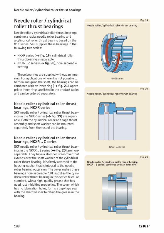
Needle roller / cylindrical roller thrust bearings
Needle roller / cylindrical roller thrust bearingsNeedle roller / cylindrical roller thrust bearings combine a radial needle roller bearing and a cylindrical roller thrust bearing based on the 811 series. SKF supplies these bearings in the following two series:
• NKXR series († fig. 19), cylindrical roller thrust bearing is separable • NKXR .. Z series († fig. 20), non-separable
bearing
These bearings are supplied without an inner ring. For applications where it is not possible to harden and grind the shaft, the bearings can be combined with an inner ring († fig. 21). Appro-priate inner rings are listed in the product tables and can be ordered separately.
Needle roller / cylindrical roller thrust bearings, NKXR seriesSKF needle roller / cylindrical roller thrust bear-ings in the NKXR series († fig. 19) are separ-able. Both the cylindrical roller and cage thrust assembly and shaft washer can be mounted separately from the rest of the bearing.
Needle roller / cylindrical roller thrust bearings, NKXR .. Z seriesSKF needle roller / cylindrical roller thrust bear-ings in the NKXR .. Z series († fig. 20) are non-separable. They have a stamped steel cover that extends over the shaft washer of the cylindrical roller thrust bearing. It is firmly attached to the housing washer that is integral to the needle roller bearing outer ring. The cover makes these bearings non-separable. SKF supplies the cylin-drical roller thrust bearing in this series filled, as standard, with a high-quality grease that has good rust inhibiting properties. The cover, which has no lubrication holes, forms a gap-type seal with the shaft washer to retain the grease in the bearing.
Fig. 19
Needle roller / cylindrical roller thrust bearing
Fig. 20
Needle roller / cylindrical roller thrust bearing
Fig. 21
Needle roller / cylindrical roller thrust bearing, NKXR .. Z series, combined with an inner ring
NKXR series
NKXR .. Z series
188
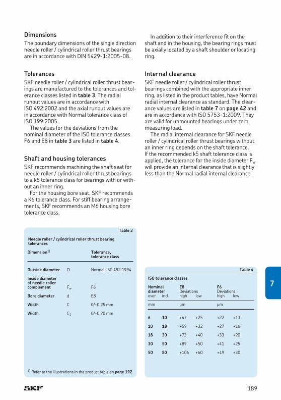
DimensionsThe boundary dimensions of the single direction needle roller / cylindrical roller thrust bearings are in accordance with DIN 5429-1:2005-08.
TolerancesSKF needle roller / cylindrical roller thrust bear-ings are manufactured to the tolerances and tol-erance classes listed in table 3. The radial runout values are in accordance with ISO 492:2002 and the axial runout values are in accordance with Normal tolerance class of ISO 199:2005.
The values for the deviations from the nominal diameter of the ISO tolerance classes F6 and E8 in table 3 are listed in table 4.
Shaft and housing tolerancesSKF recommends machining the shaft seat for needle roller / cylindrical roller thrust bearings to a k5 tolerance class for bearings with or with-out an inner ring.
For the housing bore seat, SKF recommends a K6 tolerance class. For stiff bearing arrange-ments, SKF recommends an M6 housing bore tolerance class.
Table 3
Needle roller / cylindrical roller thrust bearing tolerances
Dimension1) Tolerance, tolerance class
Outside diameter D Normal, ISO 492:1994
Inside diameter of needle rollercomplement Fw F6
Bore diameter d E8
Width C 0/–0,25 mm
Width C1 0/–0,20 mm
Table 4
ISO tolerance classes
Nominal E8 F6diameter Deviations Deviationsover incl. high low high low
mm μm μm
6 10 +47 +25 +22 +13
10 18 +59 +32 +27 +16
18 30 +73 +40 +33 +20
30 50 +89 +50 +41 +25
50 80 +106 +60 +49 +30
1) Refer to the illustrations in the product table on page 192
In addition to their interference fit on the shaft and in the housing, the bearing rings must be axially located by a shaft shoulder or locating ring.
Internal clearanceSKF needle roller / cylindrical roller thrust bearings combined with the appropriate inner ring, as listed in the product tables, have Normal radial internal clearance as standard. The clear-ance values are listed in table 7 on page 42 and are in accordance with ISO 5753-1:2009. They are valid for unmounted bearings under zero measuring load.
The radial internal clearance for SKF needle roller / cylindrical roller thrust bearings without an inner ring depends on the shaft tolerance. If the recommended k5 shaft tolerance class is applied, the tolerance for the inside diameter Fw will provide an internal clearance that is slightly less than the Normal radial internal clearance.
189
7
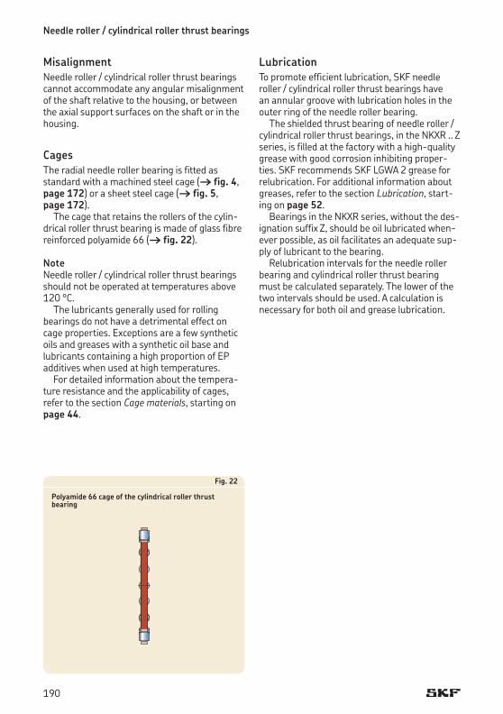
Needle roller / cylindrical roller thrust bearings
MisalignmentNeedle roller / cylindrical roller thrust bearings cannot accommodate any angular misalignment of the shaft relative to the housing, or between the axial support surfaces on the shaft or in the housing.
CagesThe radial needle roller bearing is fitted as standard with a machined steel cage († fig. 4, page 172) or a sheet steel cage († fig. 5, page 172).
The cage that retains the rollers of the cylin-drical roller thrust bearing is made of glass fibre reinforced polyamide 66 († fig. 22).
NoteNeedle roller / cylindrical roller thrust bearings should not be operated at temperatures above 120 °C.
The lubricants generally used for rolling bearings do not have a detrimental effect on cage properties. Exceptions are a few synthetic oils and greases with a synthetic oil base and lubricants containing a high proportion of EP additives when used at high temperatures.
For detailed information about the tempera-ture resistance and the applicability of cages, refer to the section Cage materials, starting on page 44.
Fig. 22
Polyamide 66 cage of the cylindrical roller thrust bearing
Lubrication To promote efficient lubrication, SKF needle roller / cylindrical roller thrust bearings have an annular groove with lubrication holes in the outer ring of the needle roller bearing.
The shielded thrust bearing of needle roller / cylindrical roller thrust bearings, in the NKXR .. Z series, is filled at the factory with a high-quality grease with good corrosion inhibiting proper-ties. SKF recommends SKF LGWA 2 grease for relubrication. For additional information about greases, refer to the section Lubrication, start-ing on page 52.
Bearings in the NKXR series, without the des-ignation suffix Z, should be oil lubricated when-ever possible, as oil facilitates an adequate sup-ply of lubricant to the bearing.
Relubrication intervals for the needle roller bearing and cylindrical roller thrust bearing must be calculated separately. The lower of the two intervals should be used. A calculation is necessary for both oil and grease lubrication.
190
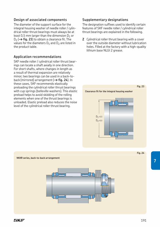
Design of associated componentsThe diameter of the support surface for the integral housing washer of needle roller / cylin-drical roller thrust bearings must always be at least 0,5 mm larger than the dimension D1 or D2 († fig. 23) to obtain a clearance fit. The values for the diameters D1 and D2 are listed in the product table.
Application recommendationsSKF needle roller / cylindrical roller thrust bear-ings can locate a shaft axially in one direction. For short shafts, where changes in length as a result of thermal expansion are relatively minor, two bearings can be used in a back-to-back (mirrored) arrangement († fig. 24). In these cases, SKF recommends elastically preloading the cylindrical roller thrust bearings with cup springs (belleville washers). This elastic preload helps to avoid skidding of the rolling elements when one of the thrust bearings is unloaded. Elastic preload also reduces the noise level of the cylindrical roller thrust bearing.
Fig. 23
Clearance fit for the integral housing washer
D1D2
+0,5
+0,5
Fig. 24
NKXR series, back-to-back arrangement
Supplementary designationsThe designation suffixes used to identify certain features of SKF needle roller / cylindrical roller thrust bearings are explained in the following.
Z Cylindrical roller thrust bearing with a cover over the outside diameter without lubrication holes. Filled at the factory with a high-quality lithium base NLGI 2 grease.
191
7
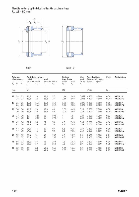
Needle roller / cylindrical roller thrust bearingsFw 15 – 50 mm
15 24 23 11,2 14 11,2 27 1,66 2,45 0,058 4 300 8 500 0,042 NKXR 15 24 23 11,2 14 11,2 27 1,66 2,45 0,058 4 300 8 500 0,045 NKXR 15 Z 17 26 25 12,3 16,6 12,2 31,5 1,96 2,85 0,079 4 300 8 500 0,05 NKXR 17 26 25 12,3 16,6 12,2 31,5 1,96 2,85 0,079 4 300 8 500 0,053 NKXR 17 Z 20 30 30 16,8 26 18,6 48 3,05 4,65 0,18 3 800 7 500 0,08 NKXR 20 30 30 16,8 26 18,6 48 3,05 4,65 0,18 3 800 7 500 0,084 NKXR 20 Z 25 37 30 19 32,5 25 69,5 4 6,8 0,39 3 200 6 300 0,12 NKXR 25 37 30 19 32,5 25 69,5 4 6,8 0,39 3 200 6 300 0,13 NKXR 25 Z 30 42 30 22,9 39 27 78 4,8 7,65 0,49 3 000 6 000 0,14 NKXR 30 42 30 22,9 39 27 78 4,8 7,65 0,49 3 000 6 000 0,14 NKXR 30 Z 35 47 30 24,6 45 29 93 5,6 9,15 0,69 2 800 5 600 0,16 NKXR 35 47 30 24,6 45 29 93 5,6 9,15 0,69 2 800 5 600 0,17 NKXR 35 Z 40 52 32 26,4 51 43 137 6,3 13,7 1,5 2 400 5 000 0,2 NKXR 40 52 32 26,4 51 43 137 6,3 13,7 1,5 2 400 5 000 0,21 NKXR 40 Z 45 58 32 28,1 57 45 153 7,1 15,3 1,9 2 200 4 500 0,24 NKXR 45 58 32 28,1 57 45 153 7,1 15,3 1,9 2 200 4 500 0,26 NKXR 45 Z 50 62 35 38 80 47,5 166 9,65 16,6 2,2 2 200 4 300 0,27 NKXR 50 62 35 38 80 47,5 166 9,65 16,6 2,2 2 200 4 300 0,29 NKXR 50 Z
Principal Basic load ratings Fatigue Min. Speed ratings Mass Designationdimensions radial axial load limits load Reference Limiting dynamic static dynamic static radial axial factor speed speed Fw D C C C0 C C0 Pu Pu A mm kN kN – r/min kg –
Fw
C1 C2
C
r1
Dd
r2
r2r1
D1 D2
NKXR NKXR .. Z
192
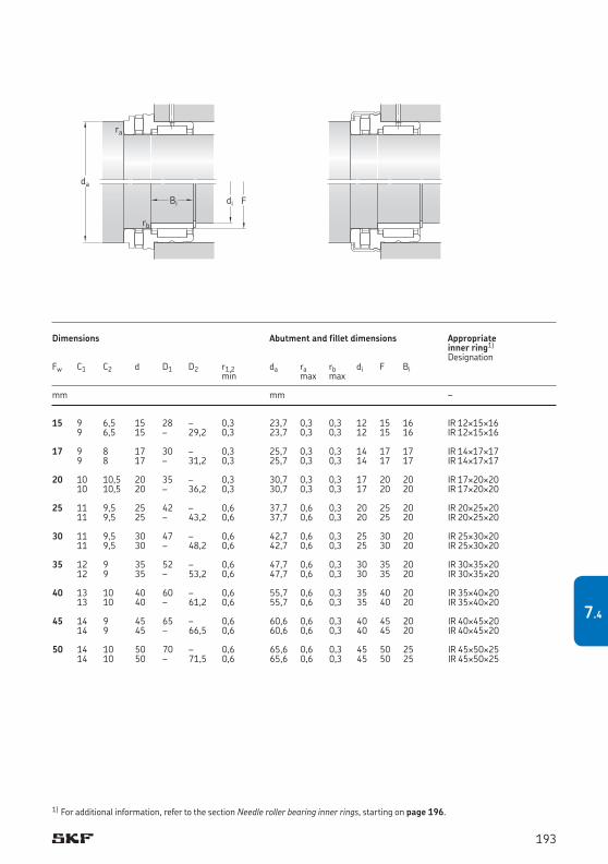
15 9 6,5 15 28 – 0,3 23,7 0,3 0,3 12 15 16 IR 12¥15¥16 9 6,5 15 – 29,2 0,3 23,7 0,3 0,3 12 15 16 IR 12¥15¥16 17 9 8 17 30 – 0,3 25,7 0,3 0,3 14 17 17 IR 14¥17¥17 9 8 17 – 31,2 0,3 25,7 0,3 0,3 14 17 17 IR 14¥17¥17 20 10 10,5 20 35 – 0,3 30,7 0,3 0,3 17 20 20 IR 17¥20¥20 10 10,5 20 – 36,2 0,3 30,7 0,3 0,3 17 20 20 IR 17¥20¥20 25 11 9,5 25 42 – 0,6 37,7 0,6 0,3 20 25 20 IR 20¥25¥20 11 9,5 25 – 43,2 0,6 37,7 0,6 0,3 20 25 20 IR 20¥25¥20 30 11 9,5 30 47 – 0,6 42,7 0,6 0,3 25 30 20 IR 25¥30¥20 11 9,5 30 – 48,2 0,6 42,7 0,6 0,3 25 30 20 IR 25¥30¥20 35 12 9 35 52 – 0,6 47,7 0,6 0,3 30 35 20 IR 30¥35¥20 12 9 35 – 53,2 0,6 47,7 0,6 0,3 30 35 20 IR 30¥35¥20 40 13 10 40 60 – 0,6 55,7 0,6 0,3 35 40 20 IR 35¥40¥20 13 10 40 – 61,2 0,6 55,7 0,6 0,3 35 40 20 IR 35¥40¥20 45 14 9 45 65 – 0,6 60,6 0,6 0,3 40 45 20 IR 40¥45¥20 14 9 45 – 66,5 0,6 60,6 0,6 0,3 40 45 20 IR 40¥45¥20 50 14 10 50 70 – 0,6 65,6 0,6 0,3 45 50 25 IR 45¥50¥25 14 10 50 – 71,5 0,6 65,6 0,6 0,3 45 50 25 IR 45¥50¥25
Dimensions Abutment and fillet dimensions Appropriate inner ring1)
DesignationFw C1 C2 d D1 D2 r1,2 da ra rb di F Bi min max max
mm mm –
1) For additional information, refer to the section Needle roller bearing inner rings, starting on page 196.
di FBi
rb
ra
da
193
7.4
Needle roller bearing inner rings ............................................................................. 196Inner rings in the IR series ............................................................................................................ 196
Tolerances ................................................................................................................................ 196Internal clearance .................................................................................................................... 197Raceways with a machining allowance ................................................................................... 197
Inner rings in the LR series ........................................................................................................... 197Tolerances ................................................................................................................................ 198
Inner ring seats ............................................................................................................................. 198Shaft diameter tolerances ....................................................................................................... 198Cylindricity ................................................................................................................................ 198Runout ...................................................................................................................................... 198
Supplementary designations ........................................................................................................ 199Product tables ................................................................................................................................ 2008.1 Needle roller bearing inner rings ......................................................................................... 200
Needle rollers ........................................................................................................ 204Materials ........................................................................................................................................ 204Tolerances ...................................................................................................................................... 204Supplementary designations ........................................................................................................ 205Product tables ................................................................................................................................ 2068.2 Needle rollers ........................................................................................................................ 206
Radial shaft seals with a low cross sectional height ................................................... 208G design radial shaft seals............................................................................................................. 208SD design radial shaft seals .......................................................................................................... 208Design of associated components ................................................................................................ 209Speeds ........................................................................................................................................... 210Operating temperature range ....................................................................................................... 210Mounting instructions ................................................................................................................... 210Product tables ................................................................................................................................ 2128.3 Radial shaft seals with a low cross sectional height ............................................................ 212
Needle roller bearing components
8
195
8
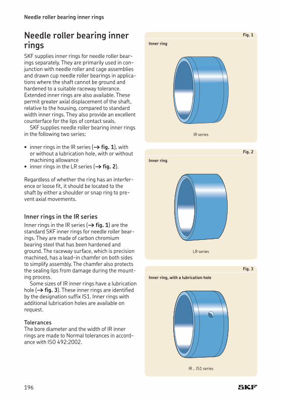
Needle roller bearing inner rings
Needle roller bearing inner ringsSKF supplies inner rings for needle roller bear-ings separately. They are primarily used in con-junctionwithneedlerollerandcageassembliesand drawn cup needle roller bearings in applica-tions where the shaft cannot be ground and hardened to a suitable raceway tolerance. Extended inner rings are also available. These permit greater axial displacement of the shaft, relative to the housing, compared to standard width inner rings. They also provide an excellent counterface for the lips of contact seals.
SKF supplies needle roller bearing inner rings in the following two series:
• innerringsintheIR series († fig. 1), with or without a lubrication hole, with or without machining allowance• innerringsintheLR series († fig. 2).
Regardless of whether the ring has an interfer-ence or loose fit, it should be located to the shaft by either a shoulder or snap ring to pre-vent axial movements.
Inner rings in the IR series Inner rings in the IR series († fig. 1) are the standard SKF inner rings for needle roller bear-ings. They are made of carbon chromium bearing steel that has been hardened and ground. The raceway surface, which is precision machined, has a lead-in chamfer on both sides to simplify assembly. The chamfer also protects the sealing lips from damage during the mount-ing process.
Some sizes of IR inner rings have a lubrication hole († fig. 3). These inner rings are identified by the designation suffix IS1. Inner rings with additional lubrication holes are available on request.
TolerancesThe bore diameter and the width of IR inner rings are made to Normal tolerances in accord-ance with ISO 492:2002.
Fig. 1
Inner ring
Fig. 2
Inner ring
Fig. 3
Inner ring, with a lubrication hole
IR series
LR series
IR .. IS1 series
196
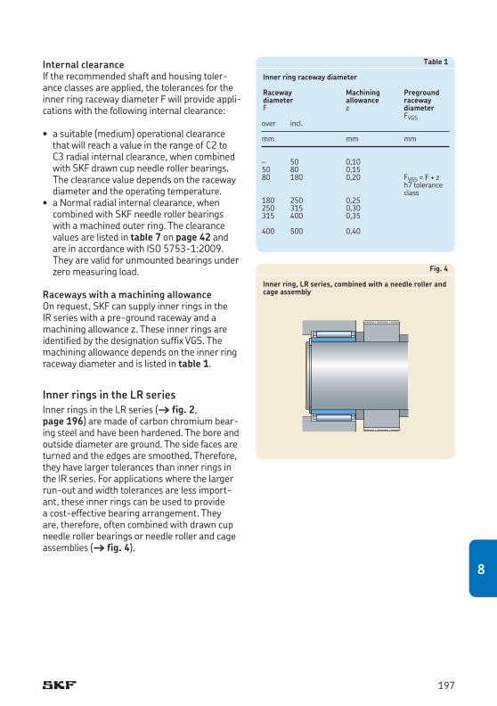
Internal clearance If the recommended shaft and housing toler-ance classes are applied, the tolerances for the inner ring raceway diameter F will provide appli-cations with the following internal clearance:
• asuitable(medium)operationalclearancethat will reach a value in the range of C2 to C3 radial internal clearance, when combined with SKF drawn cup needle roller bearings. The clearance value depends on the raceway diameter and the operating temperature. • aNormalradialinternalclearance,when
combined with SKF needle roller bearings with a machined outer ring. The clearance values are listed in table 7 on page 42 and are in accordance with ISO 5753-1:2009. They are valid for unmounted bearings under zero measuring load.
Raceways with a machining allowanceOn request, SKF can supply inner rings in the IR series with a pre-ground raceway and a machining allowance z. These inner rings are identified by the designation suffix VGS. The machining allowance depends on the inner ring raceway diameter and is listed in table 1.
Inner rings in the LR series Inner rings in the LR series († fig. 2, page 196) are made of carbon chromium bear-ing steel and have been hardened. The bore and outside diameter are ground. The side faces are turned and the edges are smoothed. Therefore, they have larger tolerances than inner rings in the IR series. For applications where the larger run-out and width tolerances are less import-ant, these inner rings can be used to provide a cost-effective bearing arrangement. They are, therefore, often combined with drawn cup needle roller bearings or needle roller and cage assemblies († fig. 4).
Table 1
Inner ring raceway diameter
Raceway Machining Pregrounddiameter allowance racewayF z diameter FVGSover incl.
mm mm mm
– 50 0,10 50 80 0,15 80 180 0,20 FVGS = F + z h7 tolerance class180 250 0,25 250 315 0,30 315 400 0,35
400 500 0,40
Fig. 4
Inner ring, LR series, combined with a needle roller and cage assembly
197
8
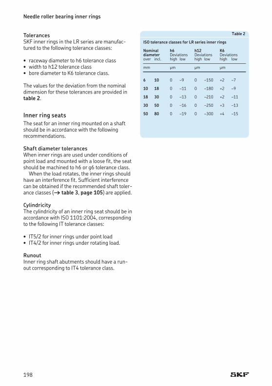
Needle roller bearing inner rings
TolerancesSKF inner rings in the LR series are manufac-tured to the following tolerance classes:
• racewaydiametertoh6toleranceclass• widthtoh12toleranceclass• borediametertoK6toleranceclass.
The values for the deviation from the nominal dimension for these tolerances are provided in table 2.
Inner ring seatsThe seat for an inner ring mounted on a shaft should be in accordance with the following recommendations.
Shaft diameter tolerances When inner rings are used under conditions of point load and mounted with a loose fit, the seat should be machined to h6 or g6 tolerance class.
When the load rotates, the inner rings should have an interference fit. Sufficient interference can be obtained if the recommended shaft toler-ance classes († table 3, page 105) are applied.
Cylindricity The cylindricity of an inner ring seat should be in accordance with ISO 1101:2004, corresponding to the following IT tolerance classes:
• IT5/2 for inner rings under point load • IT4/2 for inner rings under rotating load.
Runout Inner ring shaft abutments should have a run-out corresponding to IT4 tolerance class.
Table 2
ISO tolerance classes for LR series inner rings
Nominal h6 h12 K6diameter Deviations Deviations Deviationsover incl. high low high low high low
mm μm μm μm
6 10 0 –9 0 –150 +2 –7
10 18 0 –11 0 –180 +2 –9
18 30 0 –13 0 –210 +2 –11
30 50 0 –16 0 –250 +3 –13
50 80 0 –19 0 –300 +4 –15
198
Supplementary designationsThe designation suffixes used to identify certain features of SKF needle roller bearing inner rings are explained in the following.
EGS Inner ring with non-directionally ground raceway
IS.. Needle roller bearing with one or more lubricating holes in the inner ring, a figure following indicates the number of holes
ISR.. Needle roller bearing with an annular groove and one or more lubricating holes in the inner ring, a figure following indi-cates the number of holes
VGS Inner ring with a pre-ground raceway and a machining allowance
C2 Bearing internal clearance smaller than Normal
C3 Bearing internal clearance greater than Normal
C4 Bearing internal clearance greater than C3
199
8
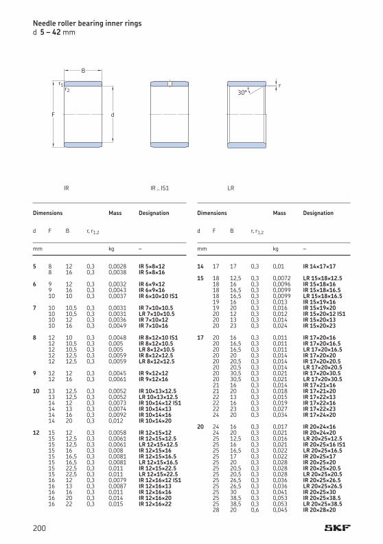
Needle roller bearing inner ringsd 5 – 42 mm
Dimensions Mass Designation
d F B r, r1,2
mm kg –
5 8 12 0,3 0,0028 IR 5¥8¥12 8 16 0,3 0,0038 IR 5¥8¥16 6 9 12 0,3 0,0032 IR 6¥9¥12 9 16 0,3 0,0043 IR 6¥9¥16 10 10 0,3 0,0037 IR 6¥10¥10 IS1 7 10 10,5 0,3 0,0031 IR 7¥10¥10.5 10 10,5 0,3 0,0031 LR 7¥10¥10.5 10 12 0,3 0,0036 IR 7¥10¥12 10 16 0,3 0,0049 IR 7¥10¥16 8 12 10 0,3 0,0048 IR 8¥12¥10 IS1 12 10,5 0,3 0,005 IR 8¥12¥10.5 12 10,5 0,3 0,005 LR 8¥12¥10.5 12 12,5 0,3 0,0059 IR 8¥12¥12.5 12 12,5 0,3 0,0059 LR 8¥12¥12.5 9 12 12 0,3 0,0045 IR 9¥12¥12 12 16 0,3 0,0061 IR 9¥12¥16 10 13 12,5 0,3 0,0052 IR 10¥13¥12.5 13 12,5 0,3 0,0052 LR 10¥13¥12.5 14 12 0,3 0,0073 IR 10¥14¥12 IS1 14 13 0,3 0,0074 IR 10¥14¥13 14 16 0,3 0,0092 IR 10¥14¥16 14 20 0,3 0,012 IR 10¥14¥20 12 15 12 0,3 0,0058 IR 12¥15¥12 15 12,5 0,3 0,0061 IR 12¥15¥12.5 15 12,5 0,3 0,0061 LR 12¥15¥12.5 15 16 0,3 0,008 IR 12¥15¥16 15 16,5 0,3 0,0081 IR 12¥15¥16.5 15 16,5 0,3 0,0081 LR 12¥15¥16.5 15 22,5 0,3 0,011 IR 12¥15¥22.5 15 22,5 0,3 0,011 LR 12¥15¥22.5 16 12 0,3 0,0079 IR 12¥16¥12 IS1 16 13 0,3 0,0087 IR 12¥16¥13 16 16 0,3 0,011 IR 12¥16¥16 16 20 0,3 0,014 IR 12¥16¥20 16 22 0,3 0,015 IR 12¥16¥22
Dimensions Mass Designation
d F B r, r1,2
mm kg –
14 17 17 0,3 0,01 IR 14¥17¥17 15 18 12,5 0,3 0,0072 LR 15¥18¥12.5 18 16 0,3 0,0096 IR 15¥18¥16 18 16,5 0,3 0,0099 IR 15¥18¥16.5 18 16,5 0,3 0,0099 LR 15¥18¥16.5 19 16 0,3 0,013 IR 15¥19¥16 19 20 0,3 0,016 IR 15¥19¥20 20 12 0,3 0,012 IR 15¥20¥12 IS1 20 13 0,3 0,014 IR 15¥20¥13 20 23 0,3 0,024 IR 15¥20¥23 17 20 16 0,3 0,011 IR 17¥20¥16 20 16,5 0,3 0,011 IR 17¥20¥16.5 20 16,5 0,3 0,011 LR 17¥20¥16.5 20 20 0,3 0,014 IR 17¥20¥20 20 20,5 0,3 0,014 IR 17¥20¥20.5 20 20,5 0,3 0,014 LR 17¥20¥20.5 20 30,5 0,3 0,021 IR 17¥20¥30.5 20 30,5 0,3 0,021 LR 17¥20¥30.5 21 16 0,3 0,014 IR 17¥21¥16 21 20 0,3 0,018 IR 17¥21¥20 22 13 0,3 0,015 IR 17¥22¥13 22 16 0,3 0,019 IR 17¥22¥16 22 23 0,3 0,027 IR 17¥22¥23 24 20 0,3 0,034 IR 17¥24¥20 20 24 16 0,3 0,017 IR 20¥24¥16 24 20 0,3 0,021 IR 20¥24¥20 25 12,5 0,3 0,016 LR 20¥25¥12.5 25 16 0,3 0,021 IR 20¥25¥16 IS1 25 16,5 0,3 0,022 LR 20¥25¥16.5 25 17 0,3 0,022 IR 20¥25¥17 25 20 0,3 0,028 IR 20¥25¥20 25 20,5 0,3 0,028 IR 20¥25¥20.5 25 20,5 0,3 0,028 LR 20¥25¥20.5 25 26,5 0,3 0,036 IR 20¥25¥26.5 25 26,5 0,3 0,036 LR 20¥25¥26.5 25 30 0,3 0,041 IR 20¥25¥30 25 38,5 0,3 0,053 IR 20¥25¥38.5 25 38,5 0,3 0,053 LR 20¥25¥38.5 28 20 0,6 0,045 IR 20¥28¥20
d
r1r2
F
B
IR LR
r30°
IR .. IS1
200
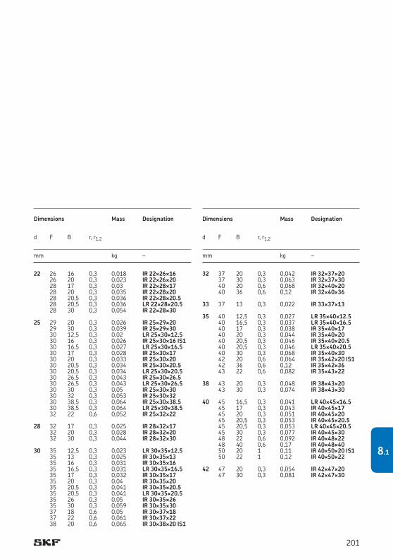
Dimensions Mass Designation
d F B r, r1,2
mm kg –
22 26 16 0,3 0,018 IR 22¥26¥16 26 20 0,3 0,023 IR 22¥26¥20 28 17 0,3 0,03 IR 22¥28¥17 28 20 0,3 0,035 IR 22¥28¥20 28 20,5 0,3 0,036 IR 22¥28¥20.5 28 20,5 0,3 0,036 LR 22¥28¥20.5 28 30 0,3 0,054 IR 22¥28¥30 25 29 20 0,3 0,026 IR 25¥29¥20 29 30 0,3 0,039 IR 25¥29¥30 30 12,5 0,3 0,02 LR 25¥30¥12.5 30 16 0,3 0,026 IR 25¥30¥16 IS1 30 16,5 0,3 0,027 LR 25¥30¥16.5 30 17 0,3 0,028 IR 25¥30¥17 30 20 0,3 0,033 IR 25¥30¥20 30 20,5 0,3 0,034 IR 25¥30¥20.5 30 20,5 0,3 0,034 LR 25¥30¥20.5 30 26,5 0,3 0,043 IR 25¥30¥26.5 30 26,5 0,3 0,043 LR 25¥30¥26.5 30 30 0,3 0,05 IR 25¥30¥30 30 32 0,3 0,053 IR 25¥30¥32 30 38,5 0,3 0,064 IR 25¥30¥38.5 30 38,5 0,3 0,064 LR 25¥30¥38.5 32 22 0,6 0,052 IR 25¥32¥22 28 32 17 0,3 0,025 IR 28¥32¥17 32 20 0,3 0,028 IR 28¥32¥20 32 30 0,3 0,044 IR 28¥32¥30 30 35 12,5 0,3 0,023 LR 30¥35¥12.5 35 13 0,3 0,025 IR 30¥35¥13 35 16 0,3 0,031 IR 30¥35¥16 35 16,5 0,3 0,031 LR 30¥35¥16.5 35 17 0,3 0,032 IR 30¥35¥17 35 20 0,3 0,04 IR 30¥35¥20 35 20,5 0,3 0,041 IR 30¥35¥20.5 35 20,5 0,3 0,041 LR 30¥35¥20.5 35 26 0,3 0,05 IR 30¥35¥26 35 30 0,3 0,059 IR 30¥35¥30 37 18 0,6 0,05 IR 30¥37¥18 37 22 0,6 0,061 IR 30¥37¥22 38 20 0,6 0,065 IR 30¥38¥20 IS1
Dimensions Mass Designation
d F B r, r1,2
mm kg –
32 37 20 0,3 0,042 IR 32¥37¥20 37 30 0,3 0,063 IR 32¥37¥30 40 20 0,6 0,068 IR 32¥40¥20 40 36 0,6 0,12 IR 32¥40¥36 33 37 13 0,3 0,022 IR 33¥37¥13 35 40 12,5 0,3 0,027 LR 35¥40¥12.5 40 16,5 0,3 0,037 LR 35¥40¥16.5 40 17 0,3 0,038 IR 35¥40¥17 40 20 0,3 0,044 IR 35¥40¥20 40 20,5 0,3 0,046 IR 35¥40¥20.5 40 20,5 0,3 0,046 LR 35¥40¥20.5 40 30 0,3 0,068 IR 35¥40¥30 42 20 0,6 0,064 IR 35¥42¥20 IS1 42 36 0,6 0,12 IR 35¥42¥36 43 22 0,6 0,082 IR 35¥43¥22 38 43 20 0,3 0,048 IR 38¥43¥20 43 30 0,3 0,074 IR 38¥43¥30 40 45 16,5 0,3 0,041 LR 40¥45¥16.5 45 17 0,3 0,043 IR 40¥45¥17 45 20 0,3 0,051 IR 40¥45¥20 45 20,5 0,3 0,053 IR 40¥45¥20.5 45 20,5 0,3 0,053 LR 40¥45¥20.5 45 30 0,3 0,077 IR 40¥45¥30 48 22 0,6 0,092 IR 40¥48¥22 48 40 0,6 0,17 IR 40¥48¥40 50 20 1 0,11 IR 40¥50¥20 IS1 50 22 1 0,12 IR 40¥50¥22 42 47 20 0,3 0,054 IR 42¥47¥20 47 30 0,3 0,081 IR 42¥47¥30
201
8.1
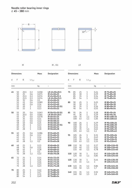
45 50 20,5 0,3 0,058 LR 45¥50¥20.5 50 25 0,6 0,071 IR 45¥50¥25 50 25,5 0,3 0,074 IR 45¥50¥25.5 50 25,5 0,3 0,074 LR 45¥50¥25.5 50 35 0,6 0,1 IR 45¥50¥35 52 22 0,6 0,089 IR 45¥52¥22 52 40 0,6 0,16 IR 45¥52¥40 55 20 1 0,12 IR 45¥55¥20 IS1 55 22 1 0,13 IR 45¥55¥22
50 55 20 0,6 0,063 IR 50¥55¥20 IS1 55 20,5 0,6 0,064 LR 50¥55¥20.5 55 25 0,6 0,078 IR 50¥55¥25 55 35 0,6 0,11 IR 50¥55¥35 58 22 0,6 0,12 IR 50¥58¥22 58 40 0,6 0,21 IR 50¥58¥40 60 20 1 0,13 IR 50¥60¥20 IS1 60 25 1 0,16 IR 50¥60¥25 60 28 1 0,18 IR 50¥60¥28
55 60 25 0,6 0,086 IR 55¥60¥25 60 35 0,6 0,12 IR 55¥60¥35 63 25 1 0,14 IR 55¥63¥25 63 45 1 0,26 IR 55¥63¥45 65 28 1,1 0,2 IR 55¥65¥28 60 68 25 1 0,15 IR 60¥68¥25 68 35 0,6 0,21 IR 60¥68¥35 68 45 1 0,28 IR 60¥68¥45 70 25 1 0,2 IR 60¥70¥25 70 28 1,1 0,22 IR 60¥70¥28 65 72 25 1 0,14 IR 65¥72¥25 72 45 1 0,26 IR 65¥72¥45 73 25 1 0,16 IR 65¥73¥25 73 35 1 0,23 IR 65¥73¥35 75 28 1,1 0,23 IR 65¥75¥28 70 80 25 1 0,22 IR 70¥80¥25 80 30 1 0,27 IR 70¥80¥30 80 35 1 0,31 IR 70¥80¥35 80 54 1 0,49 IR 70¥80¥54
Dimensions Mass Designation
d F B r, r1,2
mm kg –
Dimensions Mass Designation
d F B r, r1,2
mm kg –
75 85 25 1 0,24 IR 75¥85¥25 85 30 1 0,29 IR 75¥85¥30 85 35 1 0,34 IR 75¥85¥35 85 54 1 0,52 IR 75¥85¥54 80 90 25 1 0,25 IR 80¥90¥25 90 30 1 0,3 IR 80¥90¥30 90 35 1 0,36 IR 80¥90¥35 90 54 1 0,55 IR 80¥90¥54 85 95 26 1 0,28 IR 85¥95¥26 95 36 1 0,39 IR 85¥95¥36 100 35 1,1 0,58 IR 85¥100¥35 100 63 1,1 1,05 IR 85¥100¥63 90 100 26 1 0,29 IR 90¥100¥26 100 30 1 0,34 IR 90¥100¥30 100 36 1 0,41 IR 90¥100¥36 105 35 1,1 0,61 IR 90¥105¥35 105 63 1,1 1,1 IR 90¥105¥63 95 105 26 1 0,31 IR 95¥105¥26 105 36 1 0,43 IR 95¥105¥36 110 35 1,1 0,64 IR 95¥110¥35 110 63 1,1 1,15 IR 95¥110¥63 100 110 30 1,1 0,37 IR 100¥110¥30 110 40 1,1 0,51 IR 100¥110¥40 115 40 1,1 0,78 IR 100¥115¥40 110 120 30 1 0,41 IR 110¥120¥30 125 40 1,1 0,84 IR 110¥125¥40 120 130 30 1 0,44 IR 120¥130¥30 135 45 1,1 1 IR 120¥135¥45 130 145 35 1,1 0,86 IR 130¥145¥35 150 50 1,5 1,7 IR 130¥150¥50 140 155 35 1,1 0,92 IR 140¥155¥35 160 50 1,5 1,8 IR 140¥160¥50
Needle roller bearing inner ringsd 45 – 380 mm
d
r1r2
F
B
IR LRIR .. IS1
r30°
202
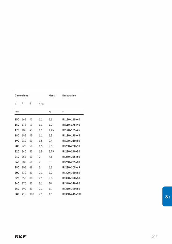
Dimensions Mass Designation
d F B r, r1,2
mm kg –
150 165 40 1,1 1,1 IR 150¥165¥40 160 175 40 1,1 1,2 IR 160¥175¥40 170 185 45 1,1 1,45 IR 170¥185¥45 180 195 45 1,1 1,5 IR 180¥195¥45 190 210 50 1,5 2,4 IR 190¥210¥50 200 220 50 1,5 2,5 IR 200¥220¥50 220 240 50 1,5 2,75 IR 220¥240¥50 240 265 60 2 4,6 IR 240¥265¥60 260 285 60 2 5 IR 260¥285¥60 280 305 69 2 6,1 IR 280¥305¥69 300 330 80 2,1 9,2 IR 300¥330¥80 320 350 80 2,1 9,8 IR 320¥350¥80 340 370 80 2,1 10 IR 340¥370¥80 360 390 80 2,1 11 IR 360¥390¥80 380 415 100 2,1 17 IR 380¥415¥100
203
8.1
Needle rollers
Needle rollersNeedle rollers can be used to make full comple-ment bearing arrangements for slow speed or oscillating applications. These compact bearing arrangements have a high load carrying cap-acity and are economical, provided the shaft and housing bore can serve as raceways. The cylin-drical surface of the rollers is slightly relieved toward the roller ends to prevent damaging edge stresses.
For additional information about surface requirements for raceways, refer to the section Raceways on shafts and in housings, starting on page 50. For assistance in designing full com-plement bearing arrangements or to calculate performance data for these bearing arrange-ments, contact the SKF application engineering service.
MaterialsSKF needle rollers are made from carbon chro-mium steel with a hardness of 58 to 65 HRC and have a precision machined surface.
TolerancesSKF needle rollers are in accordance with ISO 3096:1996 Grade 2 for flat end needle roll-ers. SKF supplies needle rollers with the dimen-sional and form tolerances as listed in table 3, where the preferred diameter deviations range from 0 to –7 μm.
Table 3
Dimensional and form accuracy of SKF needle rollers, grade G2
Diameter Dw Length LwDeviation Gauge Gauge Roundness Tolerance class tolerance limits (max circularityhigh low deviation in accordance with ISO 3096)
μm –
0 -10 2 0/–2 1 h13 –1/–3 –2/–4 –3/–5 –4/–6 –5/–7 –6/–8 –7/–9 –8/–10
The rollers are gauged according to their minimum and maximum deviation from the nom inal diameter.
Needle rollers for each gauge are packed separ ately and the package is marked with the gauge limits, e.g. N/M2 or M2/M4, where M sig-nifies minus and N zero. For a needle roller with a 2 mm nominal diameter and gauge limits M2/M4, the actual diameter is between 1,998 mm and 1,996 mm.
Note Needle rollers of the same gauge should be used in each bearing arrangement.
A delivery of needle rollers of the same nom-inal diameter may contain packages of one or more gauges, depending on availability at the time.
204

Supplementary designations
The designation suffixes used to identify certain features of SKF needle rollers are explained in the following.
BF Needle roller with flat endsG2 Needle roller in accordance with
ISO 3096:1996 Grade 2M../M.. Diameter tolerance of needle rollers,
e.g. M2/M4 indicates diameter tolerance –2 to –4 μm
N/M.. Diameter tolerance of needle rollers, e.g. N/M2 indicates diameter tolerance 0 to –2 μm
205
8
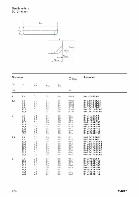
Needle rollersDw 1 – 6 mm
Dimensions Mass Designation per 1000 Dw Lw r1,2 r1 r2 min max max mm kg –
1 7,8 0,1 0,4 0,6 0,048 RN-1¥7.8 BF/G2 1,5 5,8 0,1 0,4 0,6 0,081 RN-1.5¥5.8 BF/G2 6,8 0,1 0,4 0,6 0,094 RN-1.5¥6.8 BF/G2 7,8 0,1 0,4 0,6 0,108 RN-1.5¥7.8 BF/G2 9,8 0,1 0,4 0,6 0,136 RN-1.5¥9.8 BF/G2 11,8 0,1 0,4 0,6 0,164 RN-1.5¥11.8 BF/G2 13,8 0,1 0,4 0,6 0,191 RN-1.5¥13.8 BF/G2 2 6,3 0,2 0,6 0,8 0,16 RN-2¥6.3 BF/G2 7,8 0,2 0,6 0,8 0,19 RN-2¥7.8 BF/G2 9,8 0,2 0,6 0,8 0,24 RN-2¥9.8 BF/G2 11,8 0,2 0,6 0,8 0,29 RN-2¥11.8 BF/G2 13,8 0,2 0,6 0,8 0,34 RN-2¥13.8 BF/G2 15,8 0,2 0,6 0,8 0,39 RN-2¥15.8 BF/G2 17,8 0,2 0,6 0,8 0,44 RN-2¥17.8 BF/G2 19,8 0,2 0,6 0,8 0,49 RN-2¥19.8 BF/G2 21,8 0,2 0,6 0,8 0,54 RN-2¥21.8 BF/G2 2,5 7,8 0,2 0,6 0,8 0,3 RN-2.5¥7.8 BF/G2 9,8 0,2 0,6 0,8 0,38 RN-2.5¥9.8 BF/G2 11,8 0,2 0,6 0,8 0,45 RN-2.5¥11.8 BF/G2 13,8 0,2 0,6 0,8 0,53 RN-2.5¥13.8 BF/G2 15,8 0,2 0,6 0,8 0,61 RN-2.5¥15.8 BF/G2 17,8 0,2 0,6 0,8 0,69 RN-2.5¥17.8 BF/G2 19,8 0,2 0,6 0,8 0,76 RN-2.5¥19.8 BF/G2 21,8 0,2 0,6 0,8 0,84 RN-2.5¥21.8 BF/G2 23,8 0,2 0,6 0,8 0,92 RN-2.5¥23.8 BF/G2 3 9,8 0,2 0,6 0,8 0,54 RN-3¥9.8 BF/G2 11,8 0,2 0,6 0,8 0,65 RN-3¥11.8 BF/G2 13,8 0,2 0,6 0,8 0,77 RN-3¥13.8 BF/G2 15,8 0,2 0,6 0,8 0,88 RN-3¥15.8 BF/G2 17,8 0,2 0,6 0,8 0,99 RN-3¥17.8 BF/G2 19,8 0,2 0,6 0,8 1,1 RN-3¥19.8 BF/G2 21,8 0,2 0,6 0,8 1,21 RN-3¥21.8 BF/G2 23,8 0,2 0,6 0,8 1,32 RN-3¥23.8 BF/G2
Dw
Lw
r1 min
r1 max
r2 min
r2 max
206
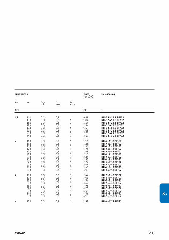
Dimensions Mass Designation per 1000 Dw Lw r1,2 r1 r2 min max max mm kg –
3,5 11,8 0,3 0,8 1 0,89 RN-3.5¥11.8 BF/G2 13,8 0,3 0,8 1 1,04 RN-3.5¥13.8 BF/G2 15,8 0,3 0,8 1 1,19 RN-3.5¥15.8 BF/G2 17,8 0,3 0,8 1 1,34 RN-3.5¥17.8 BF/G2 19,8 0,3 0,8 1 1,5 RN-3.5¥19.8 BF/G2 21,8 0,3 0,8 1 1,65 RN-3.5¥21.8 BF/G2 29,8 0,3 0,8 1 2,25 RN-3.5¥29.8 BF/G2 34,8 0,3 0,8 1 2,63 RN-3.5¥34.8 BF/G2 4 11,8 0,3 0,8 1 1,16 RN-4¥11.8 BF/G2 13,8 0,3 0,8 1 1,36 RN-4¥13.8 BF/G2 15,8 0,3 0,8 1 1,56 RN-4¥15.8 BF/G2 17,8 0,3 0,8 1 1,76 RN-4¥17.8 BF/G2 19,8 0,3 0,8 1 1,95 RN-4¥19.8 BF/G2 21,8 0,3 0,8 1 2,15 RN-4¥21.8 BF/G2 23,8 0,3 0,8 1 2,35 RN-4¥23.8 BF/G2 25,8 0,3 0,8 1 2,55 RN-4¥25.8 BF/G2 27,8 0,3 0,8 1 2,74 RN-4¥27.8 BF/G2 29,8 0,3 0,8 1 2,94 RN-4¥29.8 BF/G2 34,8 0,3 0,8 1 3,43 RN-4¥34.8 BF/G2 39,8 0,3 0,8 1 3,93 RN-4¥39.8 BF/G2 5 15,8 0,3 0,8 1 2,44 RN-5¥15.8 BF/G2 19,8 0,3 0,8 1 3,05 RN-5¥19.8 BF/G2 21,8 0,3 0,8 1 3,36 RN-5¥21.8 BF/G2 23,8 0,3 0,8 1 3,67 RN-5¥23.8 BF/G2 25,8 0,3 0,8 1 3,98 RN-5¥25.8 BF/G2 27,8 0,3 0,8 1 4,28 RN-5¥27.8 BF/G2 29,8 0,3 0,8 1 4,59 RN-5¥29.8 BF/G2 34,8 0,3 0,8 1 5,36 RN-5¥34.8 BF/G2 39,8 0,3 0,8 1 6,13 RN-5¥39.8 BF/G2 6 17,8 0,3 0,8 1 3,95 RN-6¥17.8 BF/G2
207
8.2
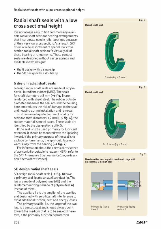
Radial shaft seals with a low cross sectional height
Radial shaft seals with a low cross sectional heightIt is not always easy to find commercially avail-able radial shaft seals for bearing arrangements that incorporate needle roller bearings because of their very low cross section. As a result, SKF offers a wide assortment of special low cross section radial shaft seals to fit virtually all of these bearing arrangements. These contact seals are designed without garter springs and available in two designs:
• theG design with a single lip• theSD design with a double lip
G design radial shaft seals G design radial shaft seals are made of acrylo-nitrile-butadiene rubber (NBR). The seals for shaft diameters ≥ 8 mm († fig. 5) are reinforced with sheet steel. The rubber outside diameter enhances the seal around the housing bore and reduces the risk of damage to the seal and housing during installation and removal.
To attain an adequate degree of rigidity for seals for shaft diameters ≤ 7 mm († fig. 6), the rubber material is metal cased. These seals are identified by the designation suffix S.
If the seal is to be used primarily for lubricant retention, it should be mounted with the lip facing inward. If the primary purpose of the seal is to exclude contaminants, the lip should face out-ward, away from the bearing († fig. 7).
For information about the chemical resistance of acrylonitrile-butadiene rubber (NBR), refer to the SKF Interactive Engineering Catalogue (sec-tion Chemical resistance).
SD design radial shaft seals SD design radial shaft seals († fig. 8) have a primary seal lip and an auxiliary dust lip. The lips are made of polyurethane (AU) and the reinforcement ring is made of polyamide (PA) instead of metal.
The auxiliary lip is the smaller of the two lips and designed with zero lip/shaft interference to avoid additional friction, heat and energy losses.
The primary seal lip, i.e. the larger of the two lips, is a contact seal and should always point toward the medium that is to be sealed. There-fore, if the primarily function is protection
Fig. 5
Radial shaft seal
Fig. 6
Radial shaft seal
Fig. 7
Needle roller bearing with machined rings with an external G design seal
Primary lip facing inward
Primary lip facing outward
G series (d1 ≥ 8 mm)
G .. S series (d1 ≤ 7 mm)
208
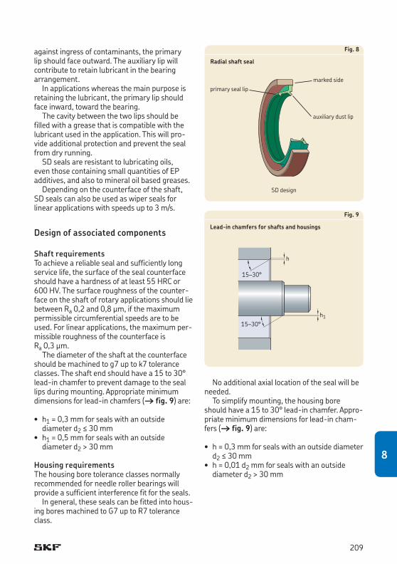
against ingress of contaminants, the primary lip should face outward. The auxiliary lip will contribute to retain lubricant in the bearing arrangement.
In applications whereas the main purpose is retaining the lubricant, the primary lip should face inward, toward the bearing.
The cavity between the two lips should be filled with a grease that is compatible with the lubricant used in the application. This will pro-vide additional protection and prevent the seal from dry running.
SD seals are resistant to lubricating oils, even those containing small quantities of EP additives, and also to mineral oil based greases.
Depending on the counterface of the shaft, SD seals can also be used as wiper seals for linear applications with speeds up to 3 m/s.
Design of associated components
Shaft requirements To achieve a reliable seal and sufficiently long service life, the surface of the seal counterface should have a hardness of at least 55HRC or 600HV. The surface roughness of the counter-face on the shaft of rotary applications should lie between Ra 0,2 and 0,8 μm, if the maximum permissible circumferential speeds are to be used. For linear applications, the maximum per-missible roughness of the counterface is Ra 0,3 μm.
The diameter of the shaft at the counterface should be machined to g7 up to k7 tolerance classes. The shaft end should have a 15 to 30° lead-in chamfer to prevent damage to the seal lips during mounting. Appropriate minimum dimensions for lead-in chamfers († fig. 9) are:
• h1 = 0,3 mm for seals with an outside diameter d2 ≤ 30 mm • h1 = 0,5 mm for seals with an outside
diameter d2 > 30 mm
Housing requirements The housing bore tolerance classes normally recommended for needle roller bearings will provide a sufficient interference fit for the seals.
In general, these seals can be fitted into hous-ing bores machined to G7 up to R7 tolerance class.
No additional axial location of the seal will be needed.
To simplify mounting, the housing bore should have a 15 to 30° lead-in chamfer. Appro-priate minimum dimensions for lead-in cham-fers († fig. 9) are:
• h = 0,3 mm for seals with an outside diameter d2 ≤ 30 mm • h = 0,01 d2 mm for seals with an outside
diameter d2 > 30 mm
Fig. 9
Lead-in chamfers for shafts and housings
h115–30°
h
15–30°
Fig. 8
Radial shaft seal
marked sideprimary seal lip
auxiliary dust lip
SD design
209
8
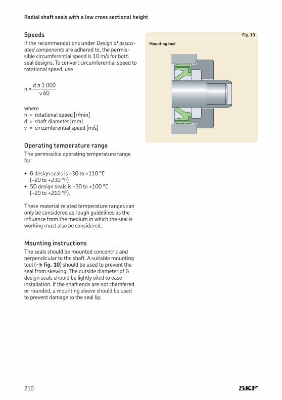
Radial shaft seals with a low cross sectional height
SpeedsIf the recommendations under Design of associated components are adhered to, the permis-sible circumferential speed is 10 m/s for both seal designs. To convert circumferential speed to rotational speed, use
d π 1 000n = –––––––– v 60
wheren = rotational speed [r/min]d = shaft diameter [mm]v = circumferential speed [m/s]
Operating temperature rangeThe permissible operating temperature range for
• G design seals is –30 to +110 °C (–20 to +230 °F) • SD design seals is –30 to +100 °C
(–20 to +210 °F).
These material related temperature ranges can only be considered as rough guidelines as the influence from the medium in which the seal is working must also be considered.
Mounting instructionsThe seals should be mounted concentric and perpendicular to the shaft. A suitable mounting tool († fig. 10) should be used to prevent the seal from skewing. The outside diameter of G design seals should be lightly oiled to ease installation. If the shaft ends are not chamfered or rounded, a mounting sleeve should be used to prevent damage to the seal lip.
Fig. 10
Mounting tool
210

211
8
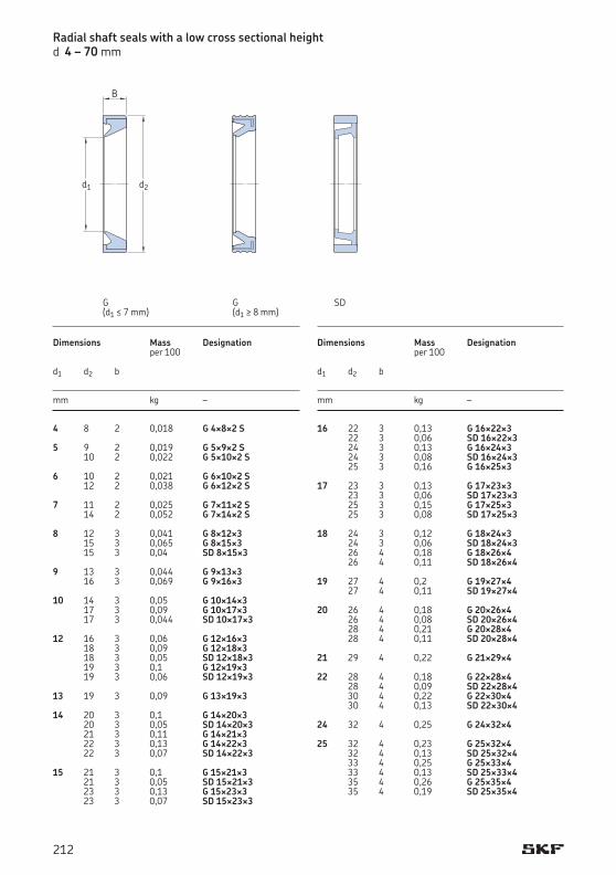
Radial shaft seals with a low cross sectional heightd 4 – 70 mm
Dimensions Mass Designation per 100
d1 d2 b
mm kg –
4 8 2 0,018 G 4¥8¥2 S 5 9 2 0,019 G 5¥9¥2 S 10 2 0,022 G 5¥10¥2 S 6 10 2 0,021 G 6¥10¥2 S 12 2 0,038 G 6¥12¥2 S 7 11 2 0,025 G 7¥11¥2 S 14 2 0,052 G 7¥14¥2 S 8 12 3 0,041 G 8¥12¥3 15 3 0,065 G 8¥15¥3 15 3 0,04 SD 8¥15¥3 9 13 3 0,044 G 9¥13¥3 16 3 0,069 G 9¥16¥3 10 14 3 0,05 G 10¥14¥3 17 3 0,09 G 10¥17¥3 17 3 0,044 SD 10¥17¥3 12 16 3 0,06 G 12¥16¥3 18 3 0,09 G 12¥18¥3 18 3 0,05 SD 12¥18¥3 19 3 0,1 G 12¥19¥3 19 3 0,06 SD 12¥19¥3 13 19 3 0,09 G 13¥19¥3 14 20 3 0,1 G 14¥20¥3 20 3 0,05 SD 14¥20¥3 21 3 0,11 G 14¥21¥3 22 3 0,13 G 14¥22¥3 22 3 0,07 SD 14¥22¥3 15 21 3 0,1 G 15¥21¥3 21 3 0,05 SD 15¥21¥3 23 3 0,13 G 15¥23¥3 23 3 0,07 SD 15¥23¥3
Dimensions Mass Designation per 100
d1 d2 b
mm kg –
16 22 3 0,13 G 16¥22¥3 22 3 0,06 SD 16¥22¥3 24 3 0,13 G 16¥24¥3 24 3 0,08 SD 16¥24¥3 25 3 0,16 G 16¥25¥3 17 23 3 0,13 G 17¥23¥3 23 3 0,06 SD 17¥23¥3 25 3 0,15 G 17¥25¥3 25 3 0,08 SD 17¥25¥3 18 24 3 0,12 G 18¥24¥3 24 3 0,06 SD 18¥24¥3 26 4 0,18 G 18¥26¥4 26 4 0,11 SD 18¥26¥4 19 27 4 0,2 G 19¥27¥4 27 4 0,11 SD 19¥27¥4 20 26 4 0,18 G 20¥26¥4 26 4 0,08 SD 20¥26¥4 28 4 0,21 G 20¥28¥4 28 4 0,11 SD 20¥28¥4 21 29 4 0,22 G 21¥29¥4 22 28 4 0,18 G 22¥28¥4 28 4 0,09 SD 22¥28¥4 30 4 0,22 G 22¥30¥4 30 4 0,13 SD 22¥30¥4 24 32 4 0,25 G 24¥32¥4 25 32 4 0,23 G 25¥32¥4 32 4 0,13 SD 25¥32¥4 33 4 0,25 G 25¥33¥4 33 4 0,13 SD 25¥33¥4 35 4 0,26 G 25¥35¥4 35 4 0,19 SD 25¥35¥4
B
d1 d2
SDG(d1 ≤ 7 mm)
G(d1 ≥ 8 mm)
212
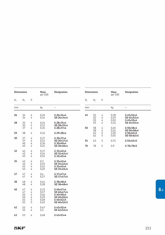
Dimensions Mass Designation per 100
d1 d2 b
mm kg –
26 34 4 0,26 G 26¥34¥4 34 4 0,14 SD 26¥34¥4 28 35 4 0,24 G 28¥35¥4 35 4 0,13 SD 28¥35¥4 37 4 0,31 G 28¥37¥4 29 38 4 0,32 G 29¥38¥4 30 37 4 0,27 G 30¥37¥4 37 4 0,13 SD 30¥37¥4 40 4 0,36 G 30¥40¥4 40 4 0,21 SD 30¥40¥4 32 42 4 0,37 G 32¥42¥4 42 4 0,24 SD 32¥42¥4 45 4 0,51 G 32¥45¥4 35 42 4 0,3 G 35¥42¥4 42 4 0,15 SD 35¥42¥4 45 4 0,41 G 35¥45¥4 45 4 0,25 SD 35¥45¥4 37 47 4 0,4 G 37¥47¥4 47 4 0,27 SD 37¥47¥4 38 48 4 0,44 G 38¥48¥4 48 4 0,28 SD 38¥48¥4 40 47 4 0,33 G 40¥47¥4 47 4 0,17 SD 40¥47¥4 50 4 0,46 G 40¥50¥4 50 4 0,29 SD 40¥50¥4 52 5 0,48 G 40¥52¥5 52 5 0,45 SD 40¥52¥5 42 52 4 0,47 G 42¥52¥4 52 4 0,3 SD 42¥52¥4 43 53 4 0,48 G 43¥53¥4
Dimensions Mass Designation per 100
d1 d2 b
mm kg –
45 52 4 0,38 G 45¥52¥4 52 4 0,19 SD 45¥52¥4 55 4 0,52 G 45¥55¥4 55 4 0,32 SD 45¥55¥4 50 58 4 0,45 G 50¥58¥4 58 4 0,24 SD 50¥58¥4 62 5 1,05 G 50¥62¥5 62 5 0,55 SD 50¥62¥5 55 63 5 0,71 G 55¥63¥5 70 78 5 0,9 G 70¥78¥5
213
8.3
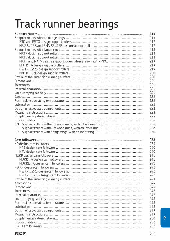
Track runner bearingsSupport rollers ...................................................................................................... 216Support rollers without flange rings ............................................................................................ 216
STO and RSTO design support rollers .................................................................................... 217NA 22...2RS and RNA 22...2RS design support rollers.......................................................... 217
Support rollers with flange rings .................................................................................................. 218NATR design support rollers ................................................................................................... 218NATV design support rollers ................................................................................................... 218NATR and NATV design support rollers, designation suffix PPA ........................................... 219NUTR .. A design support rollers ............................................................................................. 219PWTR ...2RS design support rollers ....................................................................................... 219NNTR ...2ZL design support rollers ........................................................................................ 220
Profile of the outer ring running surface ...................................................................................... 220Dimensions .................................................................................................................................... 221Tolerances ...................................................................................................................................... 221Internal clearance .......................................................................................................................... 221Load carrying capacity .................................................................................................................. 221Cages .............................................................................................................................................. 222Permissible operating temperature ............................................................................................. 222Lubrication ..................................................................................................................................... 222Design of associated components ................................................................................................ 223Mounting instructions ................................................................................................................... 223Supplementary designations ........................................................................................................ 224Product tables ................................................................................................................................ 2269.1 Support rollers without flange rings, without an inner ring ............................................... 2269.2 Support rollers without flange rings, with an inner ring .................................................... 2289.3 Support rollers with flange rings, with an inner ring .......................................................... 230
Cam followers ........................................................................................................ 238KR design cam followers ............................................................................................................... 239
KRE design cam followers ....................................................................................................... 240KRV design cam followers ....................................................................................................... 240
NUKR design cam followers .......................................................................................................... 241NUKR .. A design cam followers .............................................................................................. 241NUKRE .. A design cam followers ............................................................................................ 241
PWKR design cam followers ......................................................................................................... 242PWKR ...2RS design cam followers ......................................................................................... 242PWKRE ...2RS design cam followers ...................................................................................... 242
Profile of the outer ring running surface ...................................................................................... 243Accessories .................................................................................................................................... 244Dimensions .................................................................................................................................... 246Tolerances ...................................................................................................................................... 247Internal clearance .......................................................................................................................... 247Load carrying capacity .................................................................................................................. 248Permissible operating temperature ............................................................................................. 248Lubrication ..................................................................................................................................... 248Design of associated components ................................................................................................ 249Mounting instructions ................................................................................................................... 249Supplementary designations ........................................................................................................ 250Product tables ................................................................................................................................ 2529.4 Cam followers ....................................................................................................................... 252
9
215
9
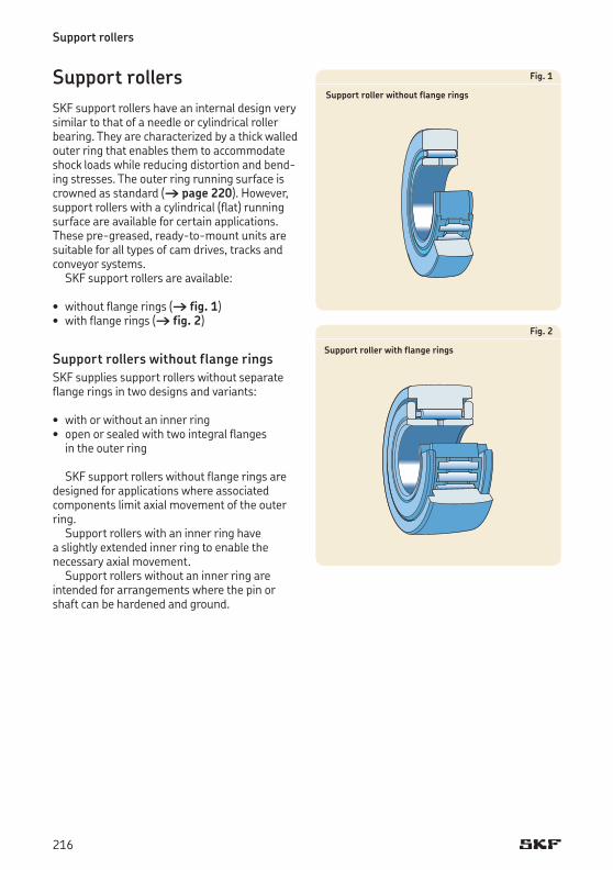
Support rollers
Support rollersSKF support rollers have an internal design very similar to that of a needle or cylindrical roller bearing. They are characterized by a thick walled outer ring that enables them to accommodate shock loads while reducing distortion and bend-ing stresses. The outer ring running surface is crowned as standard († page 220).However,support rollers with a cylindrical (flat) running surface are available for certain applications. These pre-greased, ready-to-mount units are suitable for all types of cam drives, tracks and conveyor systems.
SKF support rollers are available:
• withoutflangerings(† fig. 1) • withflangerings(† fig. 2)
Support rollers without flange ringsSKF supplies support rollers without separate flange rings in two designs and variants:
• withorwithoutaninnerring• openorsealedwithtwointegralflanges
in the outer ring
SKF support rollers without flange rings are designed for applications where associated components limit axial movement of the outer ring.
Support rollers with an inner ring have a slightly extended inner ring to enable the ne ces sary axial movement.
Support rollers without an inner ring are intended for arrangements where the pin or shaft can be hardened and ground.
Fig. 1
Support roller without flange rings
Fig. 2
Support roller with flange rings
216
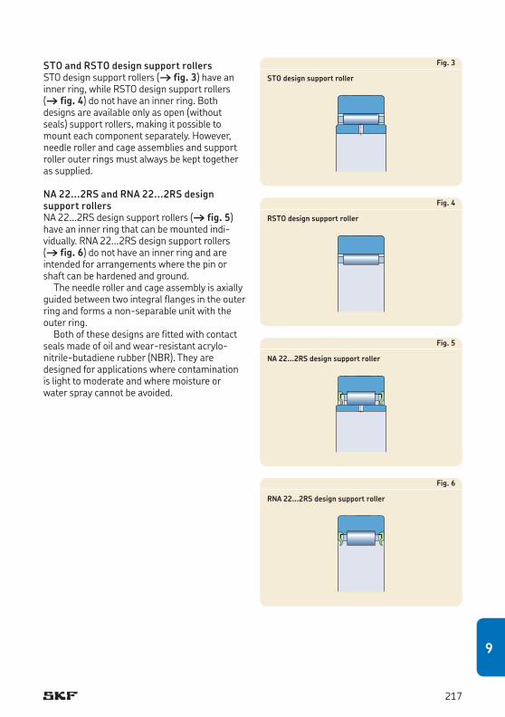
STO and RSTO design support rollers STO design support rollers († fig. 3) have an inner ring, while RSTO design support rollers († fig. 4) do not have an inner ring. Both designs are available only as open (without seals) support rollers, making it possible to mounteachcomponentseparately.However,needle roller and cage assemblies and support roller outer rings must always be kept together as supplied.
NA 22...2RS and RNA 22...2RS design support rollersNA 22...2RS design support rollers († fig. 5) have an inner ring that can be mounted indi-vidu ally. RNA 22...2RS design support rollers († fig. 6) do not have an inner ring and are intended for arrangements where the pin or shaft can be hardened and ground.
The needle roller and cage assembly is axially guided between two integral flanges in the outer ring and forms a non-separable unit with the outer ring.
Both of these designs are fitted with contact seals made of oil and wear-resistant acrylo-nitrile-butadiene rubber (NBR). They are designed for applications where contamination is light to moderate and where moisture or water spray cannot be avoided.
Fig. 3
STO design support roller
Fig. 4
RSTO design support roller
Fig. 5
NA 22...2RS design support roller
Fig. 6
RNA 22...2RS design support roller
217
9
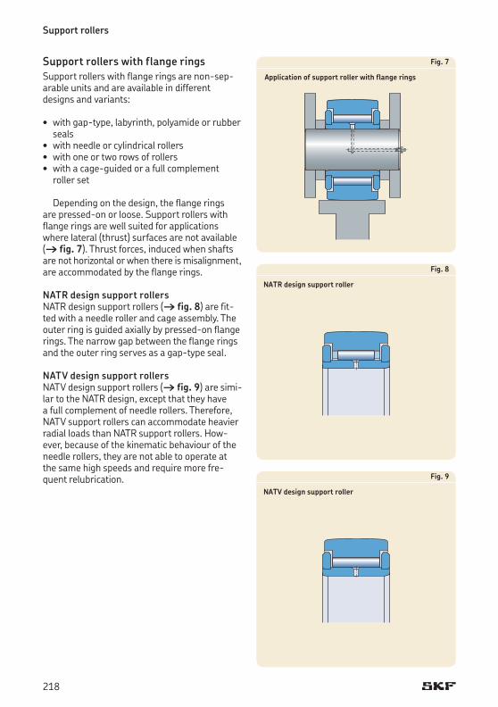
Support rollers
Support rollers with flange ringsSupport rollers with flange rings are non-sep-arable units and are available in different designs and variants:
• withgap-type,labyrinth,polyamideorrubberseals• withneedleorcylindricalrollers• withoneortworowsofrollers• withacage-guidedorafullcomplement
roller set
Depending on the design, the flange rings are pressed-on or loose. Support rollers with flange rings are well suited for applications where lateral (thrust) surfaces are not available († fig. 7). Thrust forces, induced when shafts are not horizontal or when there is misalignment, are accom modated by the flange rings.
NATR design support rollers NATR design support rollers († fig. 8) are fit-ted with a needle roller and cage assembly. The outer ring is guided axially by pressed-on flange rings. The narrow gap between the flange rings and the outer ring serves as a gap-type seal.
NATV design support rollers NATV design support rollers († fig. 9) are simi-lar to the NATR design, except that they have a full complement of needle rollers. Therefore, NATV support rollers can accommodate heavier radial loads than NATRsupportrollers.How-ever, because of the kinematic behaviour of the needle rollers, they are not able to operate at the same high speeds and require more fre-quent relubrication.
Fig. 7
Application of support roller with flange rings
Fig. 8
NATR design support roller
Fig. 9
NATV design support roller
218
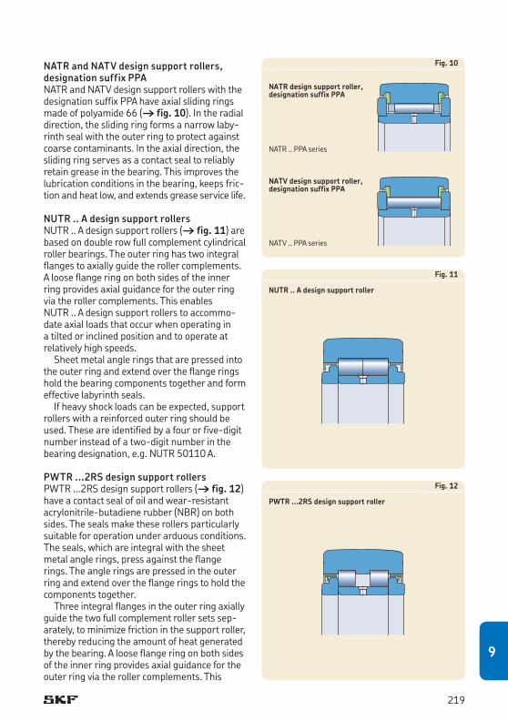
NATR and NATV design support rollers, designation suffix PPA NATR and NATV design support rollers with the designation suffix PPA have axial sliding rings made of polyamide 66 († fig. 10). In the radial direction, the sliding ring forms a narrow laby-rinth seal with the outer ring to protect against coarse contaminants. In the axial direction, the sliding ring serves as a contact seal to reliably retain grease in the bearing. This improves the lubrication conditions in the bearing, keeps fric-tion and heat low, and extends grease service life.
NUTR .. A design support rollers NUTR .. A design support rollers († fig. 11) are based on double row full complement cylindrical roller bearings. The outer ring has two integral flanges to axially guide the roller complements. A loose flange ring on both sides of the inner ring provides axial guidance for the outer ring via the roller complements. This enables NUTR .. A design support rollers to accommo-date axial loads that occur when operating in a tilted or inclined position and to operate at relatively high speeds.
Sheet metal angle rings that are pressed into the outer ring and extend over the flange rings hold the bearing components together and form effective labyrinth seals.
If heavy shock loads can be expected, support rollers with a reinforced outer ring should be used. These are identified by a four or five-digit number instead of a two-digit number in the bearing designation, e.g. NUTR 50110 A.
PWTR ...2RS design support rollers PWTR ...2RS design support rollers († fig. 12) have a contact seal of oil and wear-resistant acrylonitrile-butadiene rubber (NBR) on both sides. The seals make these rollers particularly suitable for operation under arduous conditions. The seals, which are integral with the sheet metal angle rings, press against the flange rings. The angle rings are pressed in the outer ring and extend over the flange rings to hold the components together.
Three integral flanges in the outer ring axially guide the two full complement roller sets sep-arately, to minimize friction in the support roller, thereby reducing the amount of heat generated by the bearing. A loose flange ring on both sides of the inner ring provides axial guidance for the outer ring via the roller complements. This
Fig. 10
NATR design support roller, designation suffix PPA
NATV design support roller, designation suffix PPA
Fig. 11
NUTR .. A design support roller
Fig. 12
PWTR ...2RS design support roller
NATV .. PPA series
NATR .. PPA series
219
9
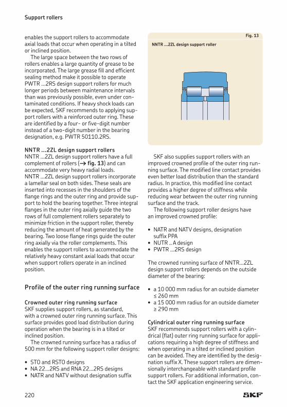
Support rollers
enables the support rollers to accommodate axial loads that occur when operating in a tilted or inclined position.
The large space between the two rows of rollers enables a large quantity of grease to be incorporated. The large grease fill and efficient sealing method make it possible to operate PWTR ...2RS design support rollers for much longer periods between maintenance intervals than was previously possible, even under con-taminated conditions. If heavy shock loads can be expected, SKF recommends to applying sup-port rollers with a reinforced outer ring. These are identified by a four- or five-digit number instead of a two-digit number in the bearing designation, e.g. PWTR 50110.2RS.
NNTR ...2ZL design support rollers NNTR ...2ZL design support rollers have a full complement of rollers († fig. 13) and can accommodate very heavy radial loads. NNTR ...2ZL design support rollers incorporate a lamellar seal on both sides. These seals are inserted into recesses in the shoulders of the flange rings and the outer ring and provide sup-port to hold the bearing together. Three integral flanges in the outer ring axially guide the two rows of full complement rollers separately to minimize friction in the support roller, thereby reducing the amount of heat generated by the bearing. Two loose flange rings guide the outer ring axially via the roller complements. This enables the support rollers to accommodate the relatively heavy constant axial loads that occur when support rollers operate in an inclined position.
Profile of the outer ring running surface
Crowned outer ring running surfaceSKF supplies support rollers, as standard, with a crowned outer ring running surface. This surface provides good load distribution during operation when the bearing is in a tilted or inclined position.
The crowned running surface has a radius of 500 mm for the following support roller designs:
• STO and RSTO designs• NA 22...2RS and RNA 22...2RS designs• NATR and NATV without designation suffix
Fig. 13
NNTR ...2ZL design support roller
SKF also supplies support rollers with an improved crowned profile of the outer ring run-ning surface. The modified line contact provides even better load distribution than the standard radius. In practice, this modified line contact provides a higher degree of stiffness while reducing wear between the outer ring running surface and the track.
The following support roller designs have an improved crowned profile:
• NATR and NATV designs, designation suffix PPA• NUTR .. A design• PWTR ...2RS design
The crowned running surface of NNTR...2ZL design support rollers depends on the outside diameter of the bearing:
• a10 000 mm radius for an outside diameter ≤ 260 mm • a15 000 mm radius for an outside diameter
≥ 290 mm
Cylindrical outer ring running surfaceSKF recommends support rollers with a cylin-drical (flat) outer ring running surface for appli-cations requiring a high degree of stiffness and when operating in a tilted or inclined position can be avoided. They are identified by the desig-nation suffix X. These support rollers are dimen-sionally interchangeable with standard profile support rollers. For additional information, con-tact the SKF application engineering service.
220
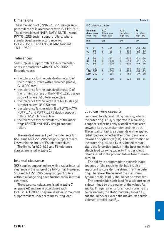
DimensionsThe dimensions of (R)NA 22...2RS design sup-port rollers are in accordance with ISO 15:1998. The dimensions of NATR, NATV, NUTR .. A and PWTR ...2RS design support rollers, where standardized, are in accordance with ISO 7063:2003 and ANSI/ABMA Standard 18.1-1982.
TolerancesSKF supplies support rollers to Normal toler-ances in accordance with ISO 492:2002. Exceptions are:
• thetolerancefortheoutsidediameterDofthe running surface with a crowned profile, 0/–0,050 mm• thetolerancefortheoutsidediameterDof
the running surface of the NNTR ...2ZL design support rollers, h10 tolerance class• thetoleranceforthewidthBofNNTR design
support rollers, 0/-0,50 mm• thetoleranceforthewidthBofNATR, NATV,
NUTR .. A and PWTR ...2RS design support rollers , h12 tolerance class• thetoleranceforthecircularityoftheinner
rings of NATR and NATV design support rollers
The inside diameter Fw of the roller sets for RSTO and RNA 22...2RS design support rollers lies within the limits of F6 tolerance class.
The limits for h10, h12 and F6 tolerance classes are listed in table 1.
Internal clearanceSKF supplies support rollers with a radial internal clearanceintherangeofC2toNormal.However,STO and NA 22...2RS design support rollers without a flange ring have Normal radial internal clearance.
The clearance values are listed in table 7 on page 42 and are in accordance with ISO 5753-1:2009. They are valid for unmounted support rollers under zero measuring load.
Load carrying capacityCompared to a typical rolling bearing, where the outer ring is fully supported in a housing, a support roller has only a small contact area between its outside diameter and the track. The actual contact area depends on the applied ra dial load and whether the running surface is crowned or cylindrical (flat). The deformation of the outer ring, caused by this limited contact, alters the force distribution in the bearing, which affects load carrying capacity. The basic load ratings listed in the product tables take this into account.
The ability to accommodate dynamic loads depends on the requisite life, but it is also important to consider the strength of the outer ring. Therefore, the value of the maximum dynamic radial load Fr should not be exceeded.
The permissible static load for a support roller is determined by the smaller of the values F0r and C0. If requirements for smooth running are below normal, the static load may exceed C0, but should never exceed the maximum permis-sible static radial load F0r.
Table 1
ISO tolerance classes
Nominal h10 h12 F6dimension Deviations Deviations Deviationsover incl. high low high low high low
mm μm μm μm
3 6 0 –48 0 –120 +18 +106 10 0 –58 0 –150 +22 +1310 18 0 –70 0 –180 +27 +16
18 30 0 –84 0 –210 +33 +2030 50 0 –100 0 –250 +41 +2550 80 0 –120 0 –300 +49 +30
80 120 0 –140 0 –350 +58 +36120 180 0 –160 0 –400 +68 +43180 250 0 –185 0 –460 +79 +50
250 315 0 –210 0 –520 +88 +56
221
9
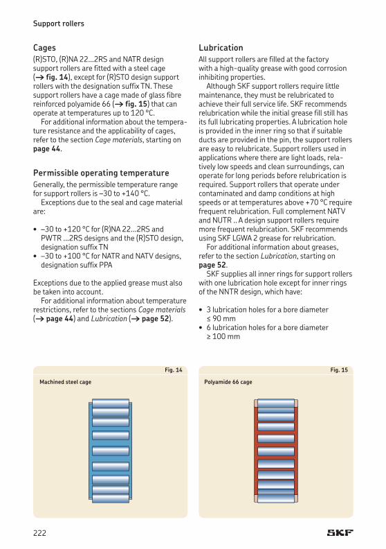
Support rollers
Cages(R)STO, (R)NA 22...2RS and NATR design support rollers are fitted with a steel cage († fig. 14), except for (R)STO design support rollers with the designation suffix TN. These support rollers have a cage made of glass fibre reinforced polyamide 66 († fig. 15) that can operate at temperatures up to 120 °C.
For additional information about the tempera-ture resistance and the applicability of cages, refer to the section Cage materials, starting on page 44.
Permissible operating temperatureGenerally, the permissible temperature range for support rollers is –30 to +140 °C.
Exceptions due to the seal and cage material are:
• –30to+120 °C for (R)NA 22...2RS and PWTR ...2RS designs and the (R)STO design, designation suffix TN• –30to+100 °C for NATR and NATV designs,
designation suffix PPA
Exceptions due to the applied grease must also be taken into account.
For additional information about temperature restrictions, refer to the sections Cage materials († page 44) and Lubrication († page 52).
Fig. 14
Machined steel cage
Fig. 15
Polyamide 66 cage
LubricationAll support rollers are filled at the factory with a high-quality grease with good corrosion inhibiting properties.
Although SKF support rollers require little maintenance, they must be relubricated to achieve their full service life. SKF recommends relubrication while the initial grease fill still has its full lubricating properties. A lubrication hole is provided in the inner ring so that if suitable ducts are provided in the pin, the support rollers are easy to relubricate. Support rollers used in applications where there are light loads, rela-tively low speeds and clean surroundings, can operate for long periods before relubrication is required. Support rollers that operate under contaminated and damp conditions at high speeds or at temperatures above +70 °C require frequent relubrication. Full complement NATV and NUTR .. A design support rollers require more frequent relubrication. SKF recom mends using SKF LGWA 2 grease for relubrication.
For additional information about greases, refer to the section Lubrication, starting on page 52.
SKF supplies all inner rings for support rollers with one lubrication hole except for inner rings of the NNTR design, which have:
• 3lubricationholesforaborediameter≤ 90 mm• 6lubricationholesforaborediameter
≥ 100 mm
222
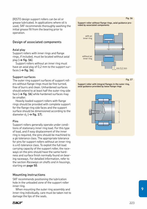
(R)STO design support rollers can be oil or grease lubricated. In applications where oil is used, SKF recommends thoroughly washing the initial grease fill from the bearing prior to operation.
Design of associated components
Axial playSupport rollers with inner rings and flange rings, if included, must be located without axial play († fig. 16).
Support rollers without an inner ring must have an axial play of 0,2 mm to the support sur-faces († fig. 16).
Support surfacesThe outer ring support surfaces of support roll-ers without flange rings must be fine turned, free of burrs and clean. Unhardened surfaces should extend to at least half the outer ring side face († fig. 16) while hardened surfaces may be smaller. Heavilyloadedsupportrollerswithflange
rings should be provided with complete support for the flange ring side faces and the support surface should be dimensioned according to the diameter d1 († fig. 17).
PinsSupport rollers generally operate under condi-tions of stationary inner ring load. For this type of load, and if easy displacement of the inner ring is required, the pins should be machined to a g6 tolerance class. The appropriate tolerance for pins for support rollers without an inner ring is a k5 tolerance class. To exploit the full load carry ing capacity of the support roller, the race-ways on the pins should have the same hard-ness and surface finish normally found on bear-ing raceways. For detailed information, refer to the section Raceways on shafts and in housings, starting on page 50.
Mounting instructionsSKF recommends positioning the lubrication hole in the unloaded zone of the support roller inner ring.
When mounting the outer ring assembly and inner ring individually, care must be taken not to damage the lips of the seals.
Fig. 16
Support roller without flange rings, axial guidance pro-vided by associated components
Fig. 17
Support roller with integral flanges in the outer ring, axial guidance provided by loose flange rings
d1
min 0,2 mm
with an inner ring
without an inner ring
223
9
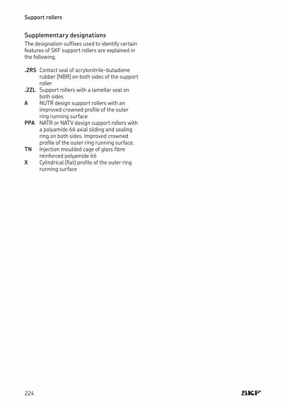
Support rollers
Supplementary designationsThe designation suffixes used to identify certain features of SKF support rollers are explained in the following.
.2RS Contact seal of acrylonitrile-butadiene rubber (NBR) on both sides of the support roller
.2ZL Support rollers with a lamellar seal on both sides
A NUTR design support rollers with an improved crowned profile of the outer ring running surface
PPA NATR or NATV design support rollers with a polyamide 66 axial sliding and sealing ring on both sides. Improved crowned profile of the outer ring running surface.
TN Injectionmouldedcageofglassfibre reinforced polyamide 66
X Cylindrical (flat) profile of the outer ring running surface
224

225
9
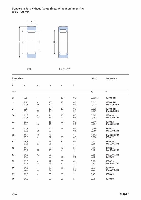
16 7,8 – 7 10 0,3 0,0085 RSTO 5 TN 19 9,8 – 10 13 0,3 0,013 RSTO 6 TN 11,8 16 10 – 0,3 0,018 RNA 22/6.2RS 24 9,8 – 12 15 0,3 0,021 RSTO 8 TN 11,8 18 12 – 0,3 0,029 RNA 22/8.2RS 30 11,8 – 14 20 0,3 0,042 RSTO 10 13,8 20 14 – 0,6 0,052 RNA 2200.2RS 32 11,8 – 16 22 0,3 0,049 RSTO 12 13,8 22 16 – 0,6 0,057 RNA 2201.2RS 35 11,8 – 20 26 0,3 0,050 RSTO 15 13,8 26 20 – 0,6 0,060 RNA 2202.2RS 40 15,8 28 22 – 1 0,094 RNA 2203.2RS 15,8 – 22 29 0,3 0,088 RSTO 17 47 15,8 – 25 32 0,3 0,13 RSTO 20 17,8 33 25 – 1 0,15 RNA 2204.2RS 52 15,8 – 30 37 0,3 0,15 RSTO 25 17,8 38 30 – 1 0,18 RNA 2205.2RS 62 19,8 43 35 – 1 0,28 RNA 2206.2RS 19,8 – 38 46 0,6 0,26 RSTO 30 72 19,8 – 42 50 0,6 0,38 RSTO 35 22,7 50 42 – 1,1 0,43 RNA 2207.2RS 80 19,8 – 50 58 1 0,42 RSTO 40 22,7 57 48 – 1,1 0,53 RNA 2208.2RS 85 19,8 – 55 63 1 0,45 RSTO 45 90 19,8 – 60 68 1 0,48 RSTO 50
Support rollers without flange rings, without an inner ringD 16 – 90 mm
Dimensions Mass Designation D C D1 Fw E r mm kg –
C
r
FwED D1
RNA 22...2RSRSTO
226
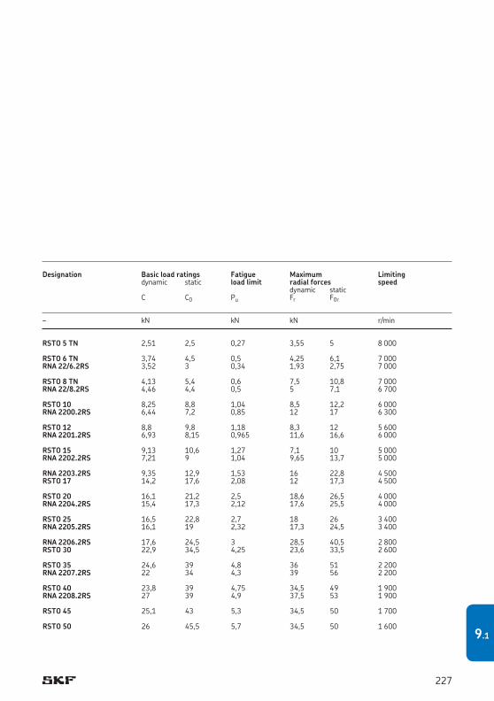
RSTO 5 TN 2,51 2,5 0,27 3,55 5 8 000
RSTO 6 TN 3,74 4,5 0,5 4,25 6,1 7 000RNA 22/6.2RS 3,52 3 0,34 1,93 2,75 7 000
RSTO 8 TN 4,13 5,4 0,6 7,5 10,8 7 000RNA 22/8.2RS 4,46 4,4 0,5 5 7,1 6 700
RSTO 10 8,25 8,8 1,04 8,5 12,2 6 000RNA 2200.2RS 6,44 7,2 0,85 12 17 6 300
RSTO 12 8,8 9,8 1,18 8,3 12 5 600RNA 2201.2RS 6,93 8,15 0,965 11,6 16,6 6 000
RSTO 15 9,13 10,6 1,27 7,1 10 5 000RNA 2202.2RS 7,21 9 1,04 9,65 13,7 5 000
RNA 2203.2RS 9,35 12,9 1,53 16 22,8 4 500RSTO 17 14,2 17,6 2,08 12 17,3 4 500
RSTO 20 16,1 21,2 2,5 18,6 26,5 4 000RNA 2204.2RS 15,4 17,3 2,12 17,6 25,5 4 000
RSTO 25 16,5 22,8 2,7 18 26 3 400RNA 2205.2RS 16,1 19 2,32 17,3 24,5 3 400
RNA 2206.2RS 17,6 24,5 3 28,5 40,5 2 800RSTO 30 22,9 34,5 4,25 23,6 33,5 2 600
RSTO 35 24,6 39 4,8 36 51 2 200RNA 2207.2RS 22 34 4,3 39 56 2 200
RSTO 40 23,8 39 4,75 34,5 49 1 900RNA 2208.2RS 27 39 4,9 37,5 53 1 900
RSTO 45 25,1 43 5,3 34,5 50 1 700
RSTO 50 26 45,5 5,7 34,5 50 1 600
Designation Basic load ratings Fatigue Maximum Limiting dynamic static load limit radial forces speed dynamic static C C0 Pu Fr F0r
– kN kN kN r/min
227
9.1
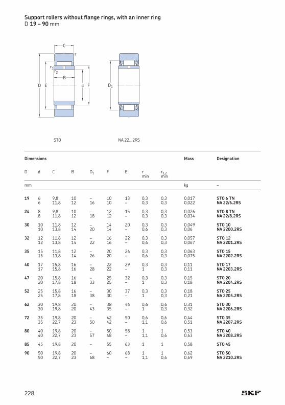
d
C
B
r1
F
r2
r
D E
Support rollers without flange rings, with an inner ringD 19 – 90 mm
19 6 9,8 10 – 10 13 0,3 0,3 0,017 STO 6 TN 6 11,8 12 16 10 – 0,3 0,3 0,022 NA 22/6.2RS 24 8 9,8 10 – 12 15 0,3 0,3 0,026 STO 8 TN 8 11,8 12 18 12 – 0,3 0,3 0,034 NA 22/8.2RS 30 10 11,8 12 – 14 20 0,3 0,3 0,049 STO 10 10 13,8 14 20 14 – 0,6 0,3 0,06 NA 2200.2RS 32 12 11,8 12 – 16 22 0,3 0,3 0,057 STO 12 12 13,8 14 22 16 – 0,6 0,3 0,067 NA 2201.2RS 35 15 11,8 12 – 20 26 0,3 0,3 0,063 STO 15 15 13,8 14 26 20 – 0,6 0,3 0,075 NA 2202.2RS 40 17 15,8 16 – 22 29 0,3 0,3 0,11 STO 17 17 15,8 16 28 22 – 1 0,3 0,11 NA 2203.2RS 47 20 15,8 16 – 25 32 0,3 0,3 0,15 STO 20 20 17,8 18 33 25 – 1 0,3 0,18 NA 2204.2RS 52 25 15,8 16 – 30 37 0,3 0,3 0,18 STO 25 25 17,8 18 38 30 – 1 0,3 0,21 NA 2205.2RS 62 30 19,8 20 – 38 46 0,6 0,6 0,31 STO 30 30 19,8 20 43 35 – 1 0,3 0,32 NA 2206.2RS 72 35 19,8 20 – 42 50 0,6 0,6 0,44 STO 35 35 22,7 23 50 42 – 1,1 0,6 0,51 NA 2207.2RS 80 40 19,8 20 – 50 58 1 1 0,53 STO 40 40 22,7 23 57 48 – 1,1 0,6 0,63 NA 2208.2RS 85 45 19,8 20 – 55 63 1 1 0,58 STO 45 90 50 19,8 20 – 60 68 1 1 0,62 STO 50 50 22,7 23 68 – – 1,1 0,6 0,69 NA 2210.2RS
Dimensions Mass Designation
D d C B D1 F E r r1,2 min min
mm kg –
STO NA 22...2RS
D1
228

STO 6 TN 3,74 4,5 0,5 4,25 6,1 7 000NA 22/6.2RS 3,52 3 0,34 1,93 2,75 7 000
STO 8 TN 4,13 5,4 0,6 7,5 10,8 7 000NA 22/8.2RS 4,46 4,4 0,5 5 7,1 6 700
STO 10 8,25 8,8 1,04 8,5 12,2 6 000NA 2200.2RS 6,44 7,2 0,85 12 17 6 300
STO 12 8,8 9,8 1,18 8,3 12 5 600NA 2201.2RS 6,93 8,15 0,965 11,6 16,6 6 000
STO 15 9,13 10,6 1,27 7,1 10 5 000NA 2202.2RS 7,21 9 1,04 9,65 13,7 5 000
STO 17 14,2 17,6 2,08 12 17,3 4 500NA 2203.2RS 9,35 12,9 1,53 16 22,8 4 500
STO 20 16,1 21,2 2,5 18,6 26,5 4 000NA 2204.2RS 15,4 17,3 2,12 17,6 25,5 4 000
STO 25 16,5 22,8 2,7 18 26 3 400NA 2205.2RS 16,1 19 2,32 17,3 24,5 3 400
STO 30 22,9 34,5 4,25 23,6 33,5 2 800NA 2206.2RS 17,6 24,5 3 28,5 40,5 2 600
STO 35 25,5 40,5 5 36 51 2 200NA 2207.2RS 22 34 4,3 39 56 2 200
STO 40 23,8 39 4,75 34,5 49 1 900NA 2208.2RS 27 39 4,9 37,5 53 1 900
STO 45 25,1 43 5,3 34,5 50 1 700
STO 50 26 45,5 5,7 34,5 50 1 600NA 2210.2RS 27 41,5 5,2 36,5 52 1 600
Designation Basic load ratings Fatigue Maximum Limiting dynamic static load limit radial forces speed dynamic static C C0 Pu Fr F0r
– kN kN kN r/min
229
9.2
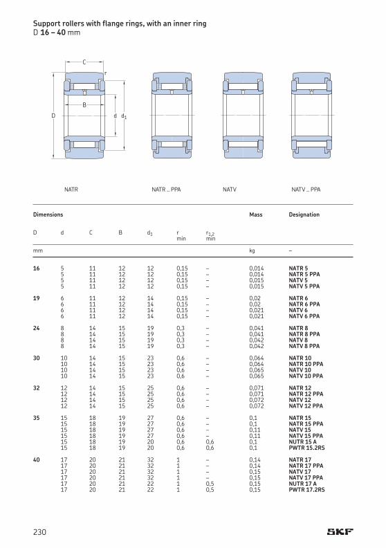
Support rollers with flange rings, with an inner ringD 16 – 40 mm
16 5 11 12 12 0,15 – 0,014 NATR 5 5 11 12 12 0,15 – 0,014 NATR 5 PPA 5 11 12 12 0,15 – 0,015 NATV 5 5 11 12 12 0,15 – 0,015 NATV 5 PPA 19 6 11 12 14 0,15 – 0,02 NATR 6 6 11 12 14 0,15 – 0,02 NATR 6 PPA 6 11 12 14 0,15 – 0,021 NATV 6 6 11 12 14 0,15 – 0,021 NATV 6 PPA 24 8 14 15 19 0,3 – 0,041 NATR 8 8 14 15 19 0,3 – 0,041 NATR 8 PPA 8 14 15 19 0,3 – 0,042 NATV 8 8 14 15 19 0,3 – 0,042 NATV 8 PPA 30 10 14 15 23 0,6 – 0,064 NATR 10 10 14 15 23 0,6 – 0,064 NATR 10 PPA 10 14 15 23 0,6 – 0,065 NATV 10 10 14 15 23 0,6 – 0,065 NATV 10 PPA 32 12 14 15 25 0,6 – 0,071 NATR 12 12 14 15 25 0,6 – 0,071 NATR 12 PPA 12 14 15 25 0,6 – 0,072 NATV 12 12 14 15 25 0,6 – 0,072 NATV 12 PPA 35 15 18 19 27 0,6 – 0,1 NATR 15 15 18 19 27 0,6 – 0,1 NATR 15 PPA 15 18 19 27 0,6 – 0,11 NATV 15 15 18 19 27 0,6 – 0,11 NATV 15 PPA 15 18 19 20 0,6 0,6 0,1 NUTR 15 A 15 18 19 20 0,6 0,6 0,1 PWTR 15.2RS 40 17 20 21 32 1 – 0,14 NATR 17 17 20 21 32 1 – 0,14 NATR 17 PPA 17 20 21 32 1 – 0,15 NATV 17 17 20 21 32 1 – 0,15 NATV 17 PPA 17 20 21 22 1 0,5 0,15 NUTR 17 A 17 20 21 22 1 0,5 0,15 PWTR 17.2RS
Dimensions Mass Designation D d C B d1 r r1,2 min min
mm kg –
d
C
B
d1
r
D
NATR NATR .. PPA NATV .. PPANATV
230
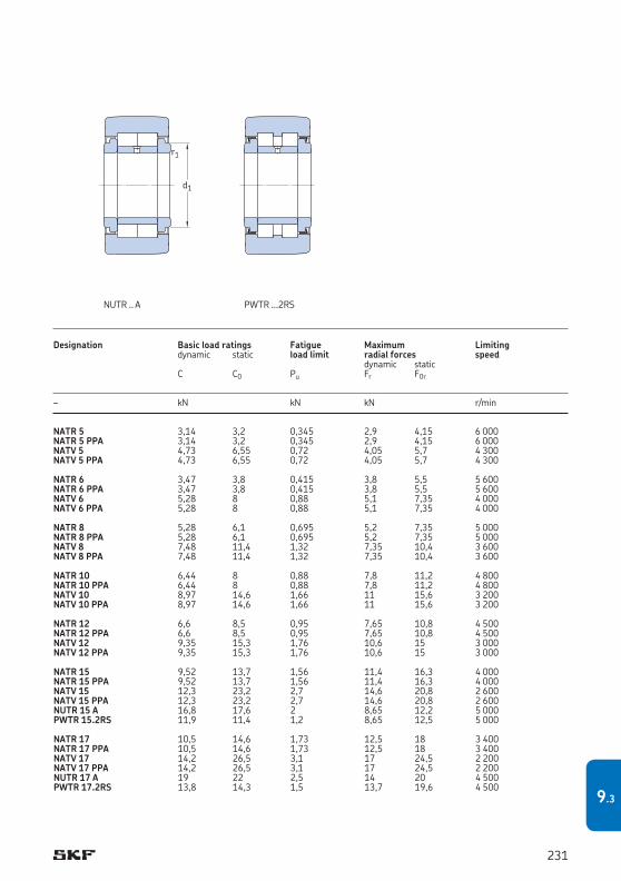
NATR 5 3,14 3,2 0,345 2,9 4,15 6 000NATR 5 PPA 3,14 3,2 0,345 2,9 4,15 6 000NATV 5 4,73 6,55 0,72 4,05 5,7 4 300NATV 5 PPA 4,73 6,55 0,72 4,05 5,7 4 300
NATR 6 3,47 3,8 0,415 3,8 5,5 5 600NATR 6 PPA 3,47 3,8 0,415 3,8 5,5 5 600NATV 6 5,28 8 0,88 5,1 7,35 4 000NATV 6 PPA 5,28 8 0,88 5,1 7,35 4 000
NATR 8 5,28 6,1 0,695 5,2 7,35 5 000NATR 8 PPA 5,28 6,1 0,695 5,2 7,35 5 000NATV 8 7,48 11,4 1,32 7,35 10,4 3 600NATV 8 PPA 7,48 11,4 1,32 7,35 10,4 3 600
NATR 10 6,44 8 0,88 7,8 11,2 4 800NATR 10 PPA 6,44 8 0,88 7,8 11,2 4 800NATV 10 8,97 14,6 1,66 11 15,6 3 200NATV 10 PPA 8,97 14,6 1,66 11 15,6 3 200
NATR 12 6,6 8,5 0,95 7,65 10,8 4 500NATR 12 PPA 6,6 8,5 0,95 7,65 10,8 4 500NATV 12 9,35 15,3 1,76 10,6 15 3 000NATV 12 PPA 9,35 15,3 1,76 10,6 15 3 000
NATR 15 9,52 13,7 1,56 11,4 16,3 4 000NATR 15 PPA 9,52 13,7 1,56 11,4 16,3 4 000NATV 15 12,3 23,2 2,7 14,6 20,8 2 600NATV 15 PPA 12,3 23,2 2,7 14,6 20,8 2 600NUTR 15 A 16,8 17,6 2 8,65 12,2 5 000PWTR 15.2RS 11,9 11,4 1,2 8,65 12,5 5 000
NATR 17 10,5 14,6 1,73 12,5 18 3 400NATR 17 PPA 10,5 14,6 1,73 12,5 18 3 400NATV 17 14,2 26,5 3,1 17 24,5 2 200NATV 17 PPA 14,2 26,5 3,1 17 24,5 2 200NUTR 17 A 19 22 2,5 14 20 4 500PWTR 17.2RS 13,8 14,3 1,5 13,7 19,6 4 500
Designation Basic load ratings Fatigue Maximum Limiting dynamic static load limit radial forces speed dynamic static C C0 Pu Fr F0r
– kN kN kN r/min
d1
r1
NUTR .. A PWTR ...2RS
231
9.3
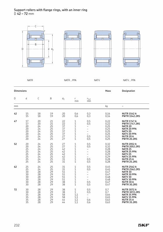
42 15 18 19 20 0,6 0,3 0,16 NUTR 1542 A 15 18 19 20 0,6 0,3 0,16 PWTR 1542.2RS 47 17 20 21 22 1 0,5 0,22 NUTR 1747 A 17 20 21 22 1 0,5 0,22 PWTR 1747.2RS 20 24 25 37 1 – 0,25 NATR 20 20 24 25 37 1 – 0,25 NATR 20 PPA 20 24 25 37 1 – 0,25 NATV 20 20 24 25 37 1 – 0,25 NATV 20 PPA 20 24 25 27 1 0,5 0,25 NUTR 20 A 20 24 25 27 1 0,5 0,25 PWTR 20.2RS 52 20 24 25 27 1 0,5 0,32 NUTR 2052 A 20 24 25 27 1 0,5 0,32 PWTR 2052.2RS 25 24 25 42 1 – 0,28 NATR 25 25 24 25 42 1 – 0,28 NATR 25 PPA 25 24 25 42 1 – 0,29 NATV 25 25 24 25 42 1 – 0,29 NATV 25 PPA 25 24 25 31 1 0,5 0,28 NUTR 25 A 25 24 25 31 1 0,5 0,28 PWTR 25.2RS 62 25 24 25 31 1 0,5 0,45 NUTR 2562 A 25 24 25 31 1 0,5 0,45 PWTR 2562.2RS 30 28 29 51 1 – 0,47 NATR 30 30 28 29 51 1 – 0,47 NATR 30 PPA 30 28 29 51 1 – 0,48 NATV 30 30 28 29 51 1 – 0,48 NATV 30 PPA 30 28 29 38 1 0,5 0,47 NUTR 30 A 30 28 29 38 1 0,5 0,47 PWTR 30.2RS 72 30 28 29 38 1 0,5 0,7 NUTR 3072 A 30 28 29 38 1 0,5 0,7 PWTR 3072.2RS 35 28 29 58 1,1 – 0,64 NATR 35 PPA 35 28 29 58 1,1 – 0,65 NATV 35 PPA 35 28 29 44 1,1 0,6 0,63 NUTR 35 A 35 28 29 44 1,1 0,6 0,63 PWTR 35.2RS
Dimensions Mass Designation D d C B d1 r r1,2 min min
mm kg –
Support rollers with flange rings, with an inner ringD 42 – 72 mm
d
C
B
d1
r
D
NATR NATR .. PPA NATV .. PPANATV
232
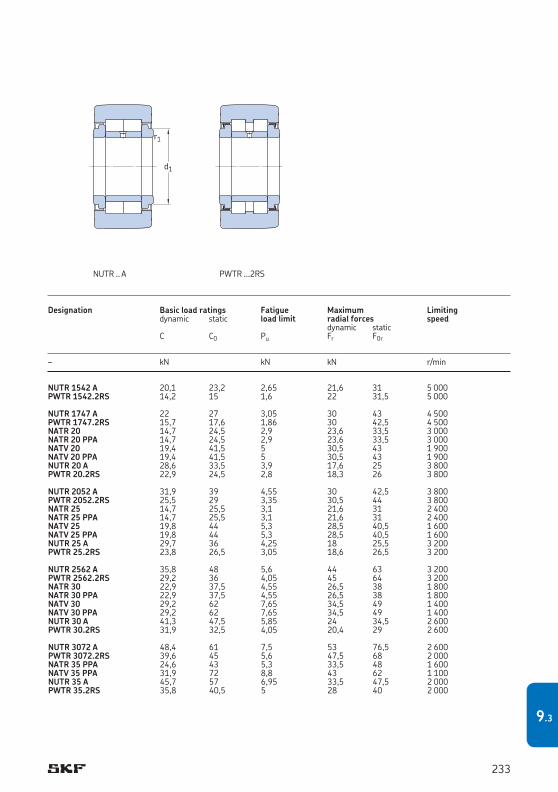
NUTR 1542 A 20,1 23,2 2,65 21,6 31 5 000PWTR 1542.2RS 14,2 15 1,6 22 31,5 5 000
NUTR 1747 A 22 27 3,05 30 43 4 500PWTR 1747.2RS 15,7 17,6 1,86 30 42,5 4 500NATR 20 14,7 24,5 2,9 23,6 33,5 3 000NATR 20 PPA 14,7 24,5 2,9 23,6 33,5 3 000NATV 20 19,4 41,5 5 30,5 43 1 900NATV 20 PPA 19,4 41,5 5 30,5 43 1 900NUTR 20 A 28,6 33,5 3,9 17,6 25 3 800PWTR 20.2RS 22,9 24,5 2,8 18,3 26 3 800
NUTR 2052 A 31,9 39 4,55 30 42,5 3 800PWTR 2052.2RS 25,5 29 3,35 30,5 44 3 800NATR 25 14,7 25,5 3,1 21,6 31 2 400NATR 25 PPA 14,7 25,5 3,1 21,6 31 2 400NATV 25 19,8 44 5,3 28,5 40,5 1 600NATV 25 PPA 19,8 44 5,3 28,5 40,5 1 600NUTR 25 A 29,7 36 4,25 18 25,5 3 200PWTR 25.2RS 23,8 26,5 3,05 18,6 26,5 3 200
NUTR 2562 A 35,8 48 5,6 44 63 3 200PWTR 2562.2RS 29,2 36 4,05 45 64 3 200NATR 30 22,9 37,5 4,55 26,5 38 1 800NATR 30 PPA 22,9 37,5 4,55 26,5 38 1 800NATV 30 29,2 62 7,65 34,5 49 1 400NATV 30 PPA 29,2 62 7,65 34,5 49 1 400NUTR 30 A 41,3 47,5 5,85 24 34,5 2 600PWTR 30.2RS 31,9 32,5 4,05 20,4 29 2 600
NUTR 3072 A 48,4 61 7,5 53 76,5 2 600PWTR 3072.2RS 39,6 45 5,6 47,5 68 2 000NATR 35 PPA 24,6 43 5,3 33,5 48 1 600NATV 35 PPA 31,9 72 8,8 43 62 1 100NUTR 35 A 45,7 57 6,95 33,5 47,5 2 000PWTR 35.2RS 35,8 40,5 5 28 40 2 000
Designation Basic load ratings Fatigue Maximum Limiting dynamic static load limit radial forces speed dynamic static C C0 Pu Fr F0r
– kN kN kN r/min
d1
r1
NUTR .. A PWTR ...2RS
233
9.3
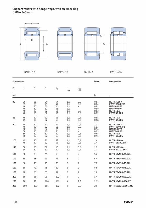
80 35 28 29 44 1,1 0,6 0,84 NUTR 3580 A 35 28 29 44 1,1 0,6 0,84 PWTR 3580.2RS 40 30 32 66 1,1 – 0,81 NATR 40 PPA 40 30 32 66 1,1 – 0,89 NATV 40 PPA 40 30 32 51 1,1 0,6 0,82 NUTR 40 A 40 30 32 51 1,1 0,6 0,82 PWTR 40.2RS 85 45 30 32 55 1,1 0,6 0,88 NUTR 45 A 45 30 32 55 1,1 0,6 0,88 PWTR 45.2RS 90 40 30 32 51 1,1 0,6 1,13 NUTR 4090 A 40 30 32 51 1,1 0,6 1,13 PWTR 4090.2RS 50 30 32 76 1,1 – 0,96 NATR 50 PPA 50 30 32 76 1,1 – 0,99 NATV 50 PPA 50 30 32 60 1,1 0,6 0,95 NUTR 50 A 50 30 32 60 1,1 0,6 0,95 PWTR 50.2RS 100 45 30 32 55 1,1 0,6 1,4 NUTR 45100 A 45 30 32 55 1,1 0,6 1,4 PWTR 45100.2RS 110 50 30 32 60 1,1 0,6 1,7 NUTR 50110 A 50 30 32 60 1,1 0,6 1,7 PWTR 50110.2RS 130 50 63 65 63 3 2 5,2 NNTR 50x130x65.2ZL 140 55 68 70 73 3 2 6,4 NNTR 55x140x70.2ZL 150 60 73 75 78 3 2 7,8 NNTR 60x150x75.2ZL 160 65 73 75 82 3 2 8,8 NNTR 65x160x75.2ZL 180 70 83 85 92 3 2 13 NNTR 70x180x85.2ZL 200 80 88 90 102 4 2 17 NNTR 80x200x90.2ZL 220 90 98 100 119 4 2,5 22,5 NNTR 90x220x100.2ZL 240 100 103 105 132 4 2,5 28 NNTR 100x240x105.2ZL
Support rollers with flange rings, with an inner ringD 80 – 240 mm
Dimensions Mass Designation D d C B d1 r r1,2 min min
mm kg –
d
C
B
d1
r
D
NATR .. PPA NATV .. PPA
d1
r1
NUTR .. A PWTR ...2RS
234
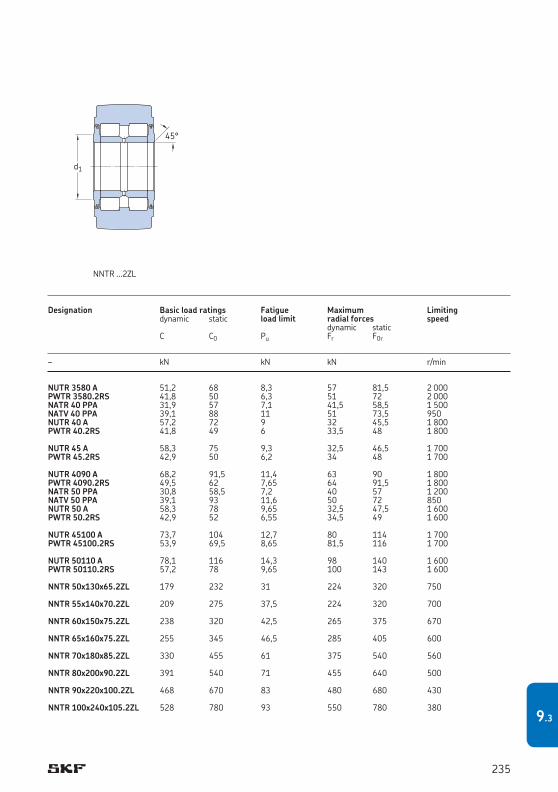
NUTR 3580 A 51,2 68 8,3 57 81,5 2 000PWTR 3580.2RS 41,8 50 6,3 51 72 2 000NATR 40 PPA 31,9 57 7,1 41,5 58,5 1 500NATV 40 PPA 39,1 88 11 51 73,5 950NUTR 40 A 57,2 72 9 32 45,5 1 800PWTR 40.2RS 41,8 49 6 33,5 48 1 800
NUTR 45 A 58,3 75 9,3 32,5 46,5 1 700PWTR 45.2RS 42,9 50 6,2 34 48 1 700
NUTR 4090 A 68,2 91,5 11,4 63 90 1 800PWTR 4090.2RS 49,5 62 7,65 64 91,5 1 800NATR 50 PPA 30,8 58,5 7,2 40 57 1 200NATV 50 PPA 39,1 93 11,6 50 72 850NUTR 50 A 58,3 78 9,65 32,5 47,5 1 600PWTR 50.2RS 42,9 52 6,55 34,5 49 1 600
NUTR 45100 A 73,7 104 12,7 80 114 1 700PWTR 45100.2RS 53,9 69,5 8,65 81,5 116 1 700
NUTR 50110 A 78,1 116 14,3 98 140 1 600PWTR 50110.2RS 57,2 78 9,65 100 143 1 600
NNTR 50x130x65.2ZL 179 232 31 224 320 750
NNTR 55x140x70.2ZL 209 275 37,5 224 320 700
NNTR 60x150x75.2ZL 238 320 42,5 265 375 670
NNTR 65x160x75.2ZL 255 345 46,5 285 405 600
NNTR 70x180x85.2ZL 330 455 61 375 540 560
NNTR 80x200x90.2ZL 391 540 71 455 640 500
NNTR 90x220x100.2ZL 468 670 83 480 680 430
NNTR 100x240x105.2ZL 528 780 93 550 780 380
Designation Basic load ratings Fatigue Maximum Limiting dynamic static load limit radial forces speed dynamic static C C0 Pu Fr F0r
– kN kN kN r/min
d1
45°
NNTR ...2ZL
235
9.3
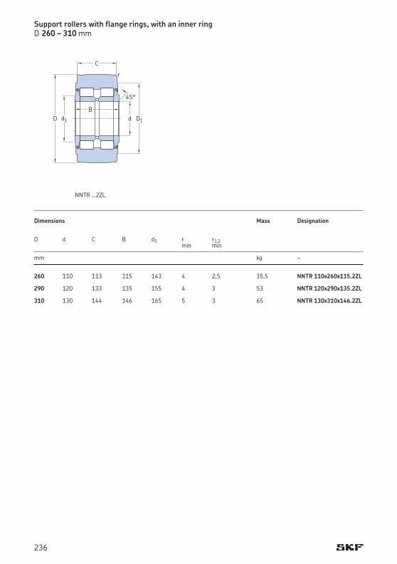
260 110 113 115 143 4 2,5 35,5 NNTR 110x260x115.2ZL 290 120 133 135 155 4 3 53 NNTR 120x290x135.2ZL 310 130 144 146 165 5 3 65 NNTR 130x310x146.2ZL
Support rollers with flange rings, with an inner ringD 260 – 310 mm
Dimensions Mass Designation D d C B d1 r r1,2 min min
mm kg –
d1
45°
d
C
BD1
r
D
NNTR ...2ZL
236
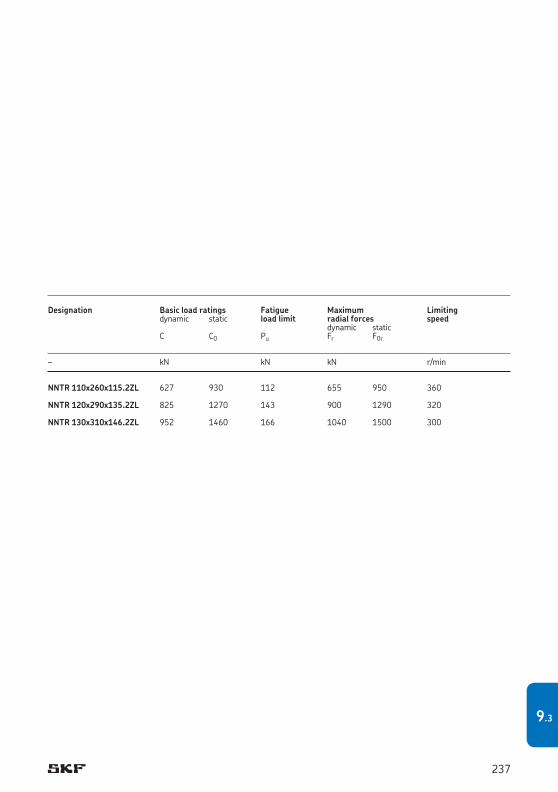
NNTR 110x260x115.2ZL 627 930 112 655 950 360
NNTR 120x290x135.2ZL 825 1270 143 900 1290 320
NNTR 130x310x146.2ZL 952 1460 166 1040 1500 300
Designation Basic load ratings Fatigue Maximum Limiting dynamic static load limit radial forces speed dynamic static C C0 Pu Fr F0r
– kN kN kN r/min
237
9.3
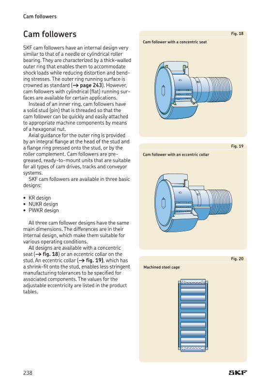
Cam followers
Cam followersSKF cam followers have an internal design very similar to that of a needle or cylindrical roller bearing. They are characterized by a thick-walled outer ring that enables them to accommodate shock loads while reducing distortion and bend-ing stresses. The outer ring running surface is crowned as standard († page 243).However,cam followers with cylindrical (flat) running sur-faces are available for certain applications.
Instead of an inner ring, cam followers have a solid stud (pin) that is threaded so that the cam follower can be quickly and easily attached to appropriate machine components by means of a hexagonal nut.
Axial guidance for the outer ring is provided by an integral flange at the head of the stud and a flange ring pressed onto the stud, or by the roller complement. Cam followers are pre-greased, ready-to-mount units that are suitable for all types of cam drives, tracks and conveyor systems.
SKF cam followers are available in three basic designs:
• KR design• NUKR design• PWKR design
All three cam follower designs have the same main dimensions. The differences are in their internal design, which make them suitable for various operating conditions.
All designs are available with a concentric seat († fig. 18) or an eccentric collar on the stud. An eccentric collar († fig. 19), which has a shrink-fit onto the stud, enables less stringent manufacturing tolerances to be specified for associated components. The values for the adjustableeccentricityarelistedintheproducttables.
Fig. 18
Cam follower with a concentric seat
Fig. 19
Cam follower with an eccentric collar
Fig. 20
Machined steel cage
238
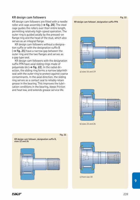
KR design cam followers KR design cam followers are fitted with a needle roller and cage assembly († fig. 20). The steel cage guides the rollers over their entire length, permitting relatively high-speed operation. The outer ring is guided axially by the pressed-on flange ring and the head of the stud, which also serves as an integral flange.
KR design cam followers without a designa-tion suffix or with the designation suffix B († fig. 21) have a narrow gap between the outer ring and the two flanges and serves as a gap type seal.
KR design cam followers with the designation suffix PPA have axial sliding rings made of polyamide 66 († fig. 22). In the radial dir-ection, the sliding ring forms a narrow labyrinth seal with the outer ring to protect against coarse contaminants. In the axial direction, the sliding ring serves as a contact seal to reliably retain grease in the bearing. This improves the lubri-cation conditions in the bearing, keeps friction and heat low, and extends grease service life.
Fig. 22
KR design cam follower, designation suffix PPA
Fig. 21
KR design cam follower, designation suffix B, sizes 22 and 26
c) from size 30
b) sizes 22 and 26
a) sizes 16 and 19
239
9
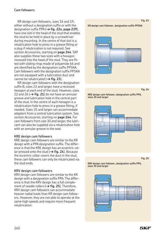
Cam followers
KR design cam followers, sizes 16 and 19, either without a designation suffix or with the designation suffix PPA († fig. 22a, page 239), have one slot in the head of the stud that enables the stud to be held in place by a screwdriver during mounting. In the centre of that slot is a relubrication hole to press in a grease fitting or a plug if relubrication is not required. See section Accessories, starting on page 244. SKF also supplies these two sizes with a hexagon recessed into the head of the stud. They are fit-ted with sliding rings made of polyamide 66 and are identified by the designation suffix PPSKA. Cam followers with the designation suffix PPSKA are not equipped with a lubrication duct and cannot be relubricated († fig. 23).
KR design cam followers with the designation suffix B, sizes 22 and larger, have a recessed hexagonateachendofthestud.However,sizes22 and 26 († fig. 21) do not have an annular groove and lubrication hole in the central part of the stud. In the centre of each hexagon is a relubrication hole to press in a grease fitting, if needed. Sizes 35 and larger can accommodate adapters from a central lubrication system. See section Accessories, starting on page 244. For cam followers from size 30 and larger, the lubri-cant can also be supplied via a relubrication hole with an annular groove in the seat.
KRE design cam followers KRE design cam followers are similar to the KR design with a PPA designation suffix. The differ-ence is that the KRE design has an eccentric col-lar pressed onto the stud († fig. 24). Because the eccentric collar covers the duct in the stud, these cam followers can only be relubricated via the stud ends.
KRV design cam followersKRV design cam followers are similar to the KR design with a designation suffix PPA. The differ-ence is that the KRV design has a full comple-ment of needle rollers († fig. 25). Therefore, KRV design cam followers can accommodate heavier radial loads than KR design cam follow-ers.However,theyarenotabletooperateatthesame high speeds and require more frequent relubrication.
Fig. 23
KR design cam follower, designation suffix PPSKA
Fig. 24
KRE design cam follower, designation suffix PPA, sizes 30 and larger
Fig. 25
KRV design cam follower, designation suffix PPA, sizes 30 and larger
240
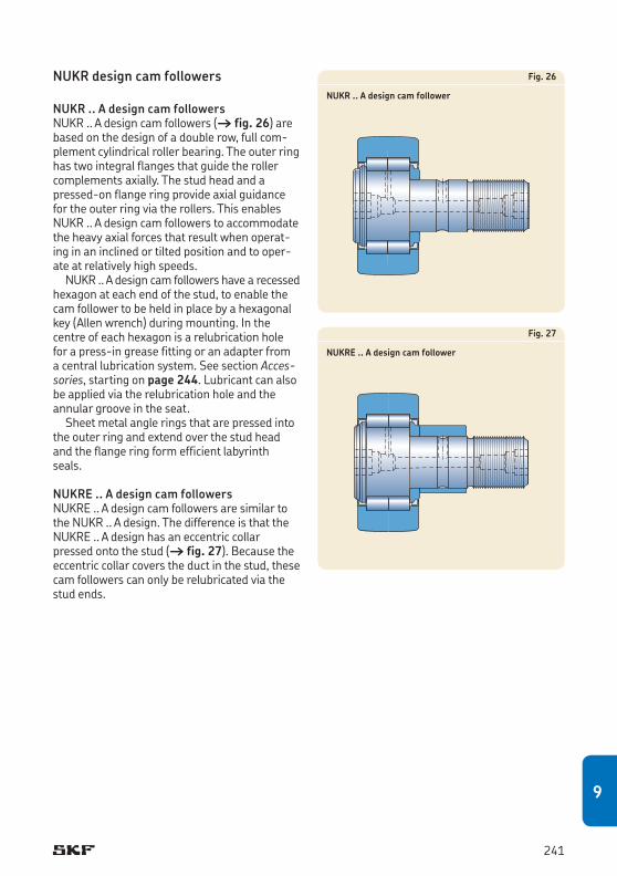
NUKR design cam followers
NUKR .. A design cam followersNUKR .. A design cam followers († fig. 26) are based on the design of a double row, full com-plement cylindrical roller bearing. The outer ring has two integral flanges that guide the roller complements axially. The stud head and a pressed-on flange ring provide axial guidance for the outer ring via the rollers. This enables NUKR .. A design cam followers to accommodate the heavy axial forces that result when operat-ing in an inclined or tilted position and to oper-ate at relatively high speeds.
NUKR .. A design cam followers have a re cessed hexa gon at each end of the stud, to enable the cam follower to be held in place by a hexagonal key (Allen wrench) during mounting. In the centre of each hexagon is a relubrication hole for a press-in grease fitting or an adapter from a central lubrication system. See section Accessories, starting on page 244. Lubricant can also be applied via the relubrication hole and the annular groove in the seat.
Sheet metal angle rings that are pressed into the outer ring and extend over the stud head and the flange ring form efficient labyrinth seals.
NUKRE .. A design cam followersNUKRE .. A design cam followers are similar to the NUKR .. A design. The difference is that the NUKRE .. A design has an eccentric collar pressed onto the stud († fig. 27). Because the eccentric collar covers the duct in the stud, these cam followers can only be relubricated via the stud ends.
Fig. 26
NUKR .. A design cam follower
Fig. 27
NUKRE .. A design cam follower
241
9
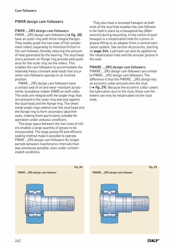
Cam followers
PWKR design cam followers
PWKR ...2RS design cam followers PWKR ...2RS design cam followers († fig. 28) have an outer ring with three integral flanges. They axially guide the two rows of full comple-ment rollers separately to minimize friction in the cam follower, thereby reducing the amount of heat generated by the bearing. The stud head and a pressed-on flange ring provide axial guid-ance for the outer ring via the rollers. This en ables the cam followers to accommodate the relatively heavy constant axial loads that occur when cam followers operate in an inclined position.
PWKR ...2RS design cam followers have a contact seal of oil and wear-resistant acrylo-nitrile-butadiene rubber (NBR) on both sides. The seals are integral with the angle rings that are pressed in the outer ring and seal against the stud head and the flange ring. The sheet metal angle rings extend over the stud head and the flange ring to form secondary labyrinth seals, making them particularly suitable for operation under arduous conditions.
The large space between the two rows of roll-ers enables a large quantity of grease to be incorporated. The large grease fill and efficient sealing method make it possible to operate PWKR ...2RS design cam followers for longer periods between maintenance intervals than was previously possible, even under contam-inated conditions.
Fig. 28
PWKR ...2RS design cam follower
Fig. 29
PWKRE ...2RS design cam follower
They also have a recessed hexagon at both ends of the stud that enables the cam follower to be held in place by a hexagonal key (Allen wrench) during mounting. In the centre of each hexagon is a relubrication hole for a press-in grease fitting or an adapter from a central lubri-cation system. See section Accessories, starting on page 244. Lubricant can also be applied via the relubrication hole and the annular groove in the seat.
PWKRE ...2RS design cam followersPWKRE ...2RS design cam followers are similar to PWKR ...2RS design cam followers. The differ ence is that the PWKRE ...2RS design has an eccentric collar pressed onto the stud († fig. 29). Because the eccentric collar covers the lubrication duct in the stud, these cam fol-lowers can only be relubricated via the stud ends.
242
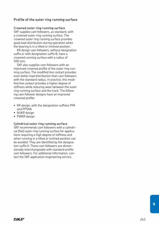
Profile of the outer ring running surface
Crowned outer ring running surfaceSKF supplies cam followers, as standard, with a crowned outer ring running surface. The crowned outer ring running surface provides good load distribution during operation when the bearing is in a tilted or inclined position.
KR design cam followers, without designation suffix or with designation suffix B, have a crowned running surface with a radius of 500 mm.
SKF also supplies cam followers with an improved crowned profile of the outer ring run-ning surface. The modified line contact provides even better load distribution than cam followers with the standard radius. In practice, this modi-fied line contact provides a higher degree of stiffness while reducing wear between the outer ring running surface and the track. The follow-ing cam follower designs have an improved crowned profile:
• KR design, with the designation suffixes PPA and PPSKA• NUKR design• PWKR design
Cylindrical outer ring running surfaceSKF recommends cam followers with a cylindri-cal (flat) outer ring running surface for applica-tions requiring a high degree of stiffness and when running in a tilted or inclined position can be avoided. They are identified by the designa-tion suffix X. These cam followers are dimen-sionally interchangeable with standard profile cam followers. For additional information, con-tact the SKF application engineering service.
243
9
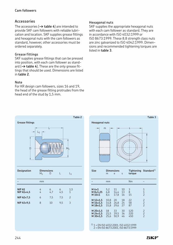
Cam followers
AccessoriesThe accessories († table 4) are intended to provide SKF cam followers with reliable lubri-cation and location. SKF supplies grease fittings and hexagonal nuts with the cam followers as standard, however, other accessories must be ordered separately.
Grease fittings SKF supplies grease fittings that can be pressed into position, with each cam follower as stand-ard († table 4). These are the only grease fit-tings that should be used. Dimensions are listed in table 2.
NoteFor KR design cam followers, sizes 16 and 19, the head of the grease fitting protrudes from the head end of the stud by 1,5 mm.
Table 3
Hexagonal nuts
Size Dimensions Tightening Standard1)
m e s torque
– mm Nm –
M 6¥1 5,2 11 10 3 1M 8¥1,25 6,8 14,4 13 8 1M 10¥1 8,4 17,8 16 15 2
M 12¥1,5 10,8 20 18 22 2M 16¥1,5 14,8 26,8 24 58 2M 18¥1,5 15,8 29,6 27 87 2
M 20¥1,5 18 33 30 120 2M 24¥1,5 21,5 39,5 36 220 2M 30¥1,5 25,6 50,9 46 450 2
Table 2
Grease fittings
Designation Dimensions M1 D L L1
– mm
NIP A1 4 6 6 1,5NIP A1¥4,5 4 4,7 4,5 1
NIP A2¥7,5 6 7,5 7,5 2
NIP A3¥9,5 8 10 9,5 3
LL1
D M1 e
sm
Hexagonal nuts SKF supplies the appropriate hexagonal nuts with each cam follower as standard. They are in accordance with ISO 4032:1999 or ISO 8673:1999. These 8.8 strength class nuts are zinc galvanized to ISO 4042:1999. Dimen-sions and recommended tightening torques are listed in table 3.
1) 1 = EN ISO 4032:2001, ISO 4032:1999 2 = EN ISO 8673:2001, ISO 8673:1999
244
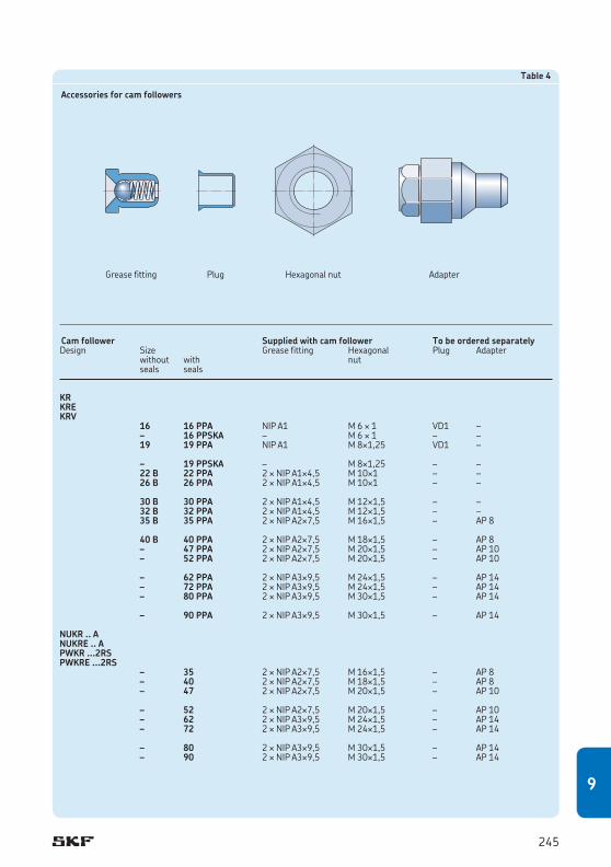
Table 4
Accessories for cam followers
Greasefitting Plug Hexagonalnut Adapter
Cam follower Supplied with cam follower To be ordered separatelyDesign Size Greasefitting Hexagonal Plug Adapter without with nut seals seals
KRKRE KRV 16 16 PPA NIP A1 M 6 ¥ 1 VD1 – – 16 PPSKA – M 6 ¥ 1 – – 19 19 PPA NIP A1 M 8¥1,25 VD1 –
– 19 PPSKA – M 8¥1,25 – – 22 B 22 PPA 2 ¥ NIP A1¥4,5 M 10¥1 – – 26 B 26 PPA 2 ¥ NIP A1¥4,5 M 10¥1 – –
30 B 30 PPA 2 ¥ NIP A1¥4,5 M 12¥1,5 – – 32 B 32 PPA 2 ¥ NIP A1¥4,5 M 12¥1,5 – – 35 B 35 PPA 2 ¥ NIP A2¥7,5 M 16¥1,5 – AP 8
40 B 40 PPA 2 ¥ NIP A2¥7,5 M 18¥1,5 – AP 8 – 47 PPA 2 ¥ NIP A2¥7,5 M 20¥1,5 – AP 10 – 52 PPA 2 ¥ NIP A2¥7,5 M 20¥1,5 – AP 10
– 62 PPA 2 ¥ NIP A3¥9,5 M 24¥1,5 – AP 14 – 72 PPA 2 ¥ NIP A3¥9,5 M 24¥1,5 – AP 14 – 80 PPA 2 ¥ NIP A3¥9,5 M 30¥1,5 – AP 14
– 90 PPA 2 ¥ NIP A3¥9,5 M 30¥1,5 – AP 14
NUKR .. ANUKRE .. APWKR ...2RSPWKRE ...2RS – 35 2 ¥ NIP A2¥7,5 M 16¥1,5 – AP 8 – 40 2 ¥ NIP A2¥7,5 M 18¥1,5 – AP 8 – 47 2 ¥ NIP A2¥7,5 M 20¥1,5 – AP 10
– 52 2 ¥ NIP A2¥7,5 M 20¥1,5 – AP 10 – 62 2 ¥ NIP A3¥9,5 M 24¥1,5 – AP 14 – 72 2 ¥ NIP A3¥9,5 M 24¥1,5 – AP 14
– 80 2 ¥ NIP A3¥9,5 M 30¥1,5 – AP 14 – 90 2 ¥ NIP A3¥9,5 M 30¥1,5 – AP 14
245
9
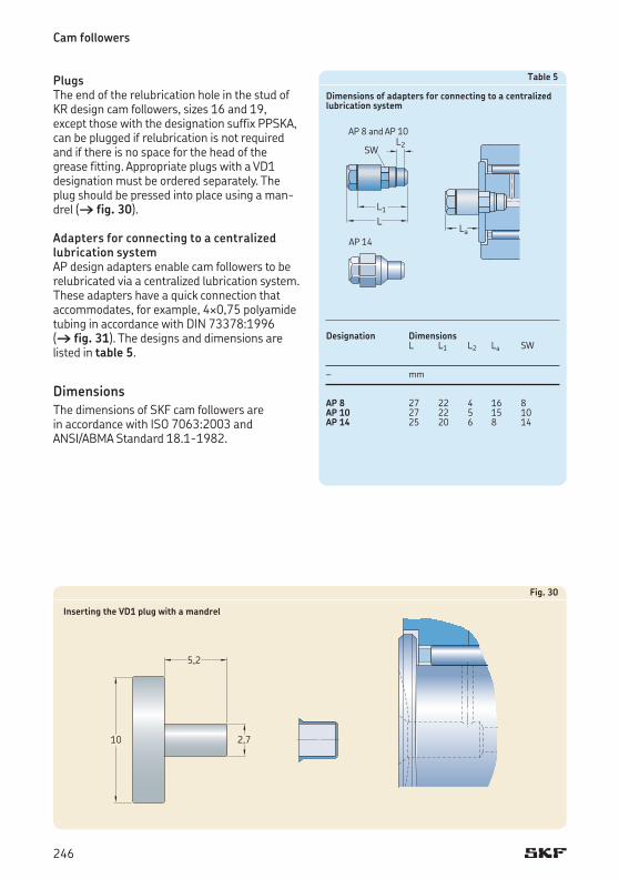
Cam followers
Plugs The end of the relubrication hole in the stud of KR design cam followers, sizes 16 and 19, except those with the designation suffix PPSKA, can be plugged if relubrication is not required and if there is no space for the head of the grease fitting. Appropriate plugs with a VD1 designation must be ordered separately. The plug should be pressed into place using a man-drel († fig. 30).
Adapters for connecting to a centralized lubrication system AP design adapters enable cam followers to be relubricated via a centralized lubrication system. These adapters have a quick connection that accommodates, for example, 4¥0,75 polyamide tubing in accordance with DIN 73378:1996 († fig. 31). The designs and dimensions are listed in table 5.
DimensionsThe dimensions of SKF cam followers are in accordance with ISO 7063:2003 and ANSI/ABMA Standard 18.1-1982.
Fig. 30
Inserting the VD1 plug with a mandrel
2,710
5,2
Table 5
Dimensions of adapters for connecting to a centralized lubrication system
Designation Dimensions L L1 L2 La SW
– mm
AP 8 27 22 4 16 8AP 10 27 22 5 15 10AP 14 25 20 6 8 14
La
L1L
L2SW
AP 8 and AP 10
AP 14
246
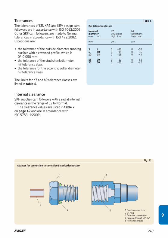
Fig. 31
Adapter for connection to centralized lubrication system
Table 6
ISO tolerance classes
Nominal h7 h9diameter Deviations Deviationsover incl. high low high low
mm μm μm
3 6 0 –12 0 –306 10 0 –15 0 –3610 18 0 –18 0 –43
18 30 0 –21 0 –5230 50 0 –25 0 –62
TolerancesThe tolerances of KR, KRE and KRV design cam followers are in accordance with ISO 7063:2003. Other SKF cam followers are made to Normal tolerances in accordance with ISO 492:2002. Exceptions are:
• thetoleranceoftheoutsidediameterrunningsurface with a crowned profile, which is 0/–0,050 mm• thetoleranceofthestudshankdiameter,
h7 tolerance class• thetolerancefortheeccentriccollardiameter,
h9 tolerance class
The limits for h7 and h9 tolerance classes are listed in table 6.
Internal clearanceSKF supplies cam followers with a radial internal clearance in the range of C2 to Normal.
The clearance values are listed in table 7 on page 42 and are in accordance with ISO 5753-1:2009.
1
2
5
3
4 1 Quick connection2 O-ring3 Adapter connection4 Female thread M 10x15 Polyamide tube
247
9
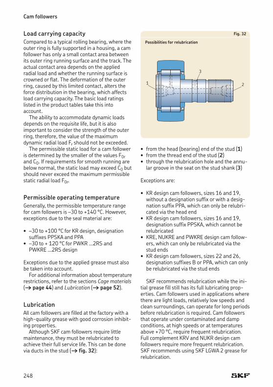
Cam followers
Load carrying capacityCompared to a typical rolling bearing, where the outer ring is fully supported in a housing, a cam follower has only a small contact area between its outer ring running surface and the track. The actual contact area depends on the applied ra dial load and whether the running surface is crowned or flat. The deformation of the outer ring, caused by this limited contact, alters the force distribution in the bearing, which affects load carrying capacity. The basic load ratings listed in the product tables take this into account.
The ability to accommodate dynamic loads depends on the requisite life, but it is also important to consider the strength of the outer ring, therefore, the value of the maximum dynamic radial load Fr should not be exceeded.
The permissible static load for a cam follower is determined by the smaller of the values F0r and C0. If requirements for smooth running are below normal, the static load may exceed C0 but should never exceed the maximum permissible static radial load F0r.
Permissible operating temperatureGenerally, the permissible temperature range for cam followers is –30 to +140 °C.However,exceptions due to the seal material are:
• –30to+100 °C for KR design, designation suffixes PPSKA and PPA
• –30to+ 120 °C for PWKR ...2RS and PWKRE ...2RS design
Exceptions due to the applied grease must also be taken into account.
For additional information about temperature restrictions, refer to the sections Cage materials († page 44) and Lubrication († page 52).
LubricationAll cam followers are filled at the factory with a high-quality grease with good corrosion inhibit-ing properties.
Although SKF cam followers require little maintenance, they must be relubricated to achieve their full service life. This can be done via ducts in the stud († fig. 32):
Fig. 32
Possibilities for relubrication
1 2
3
• fromthehead(bearing)endofthestud(1) • fromthethreadendofthestud(2)• throughtherelubricationholeandtheannu-
lar groove in the seat on the stud shank (3)
Exceptions are:
• KR design cam followers, sizes 16 and 19, without a designation suffix or with a desig-nation suffix PPA, which can only be relubri-cated via the head end• KR design cam followers, sizes 16 and 19,
designation suffix PPSKA, which cannot be relubricated • KRE, NUKRE and PWKRE design cam follow-
ers, which can only be relubricated via the stud ends• KR design cam followers, sizes 22 and 26,
designation suffixes B or PPA, which can only be relubricated via the stud ends
SKF recommends relubrication while the ini-tial grease fill still has its full lubricating prop-erties. Cam followers used in applications where there are light loads, relatively low speeds and clean surroundings, can operate for long periods before relubrication is required. Cam followers that operate under contaminated and damp conditions, at high speeds or at temperatures above +70 °C, require frequent relubrication. Full complement KRV and NUKR design cam followers require more frequent relubrication. SKF recommends using SKF LGWA 2 grease for relubrication.
248
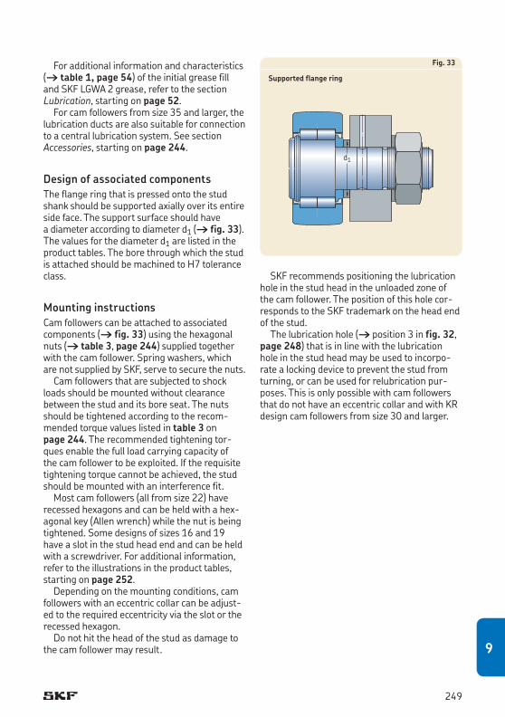
For additional information and characteristics († table 1, page 54) of the initial grease fill and SKF LGWA 2 grease, refer to the section Lubrication, starting on page 52.
For cam followers from size 35 and larger, the lubrication ducts are also suitable for connection to a central lubrication system. See section Accessories, starting on page 244.
Design of associated componentsThe flange ring that is pressed onto the stud shank should be supported axially over its entire side face. The support surface should have a diameter according to diameter d1 († fig. 33). The values for the diameter d1 are listed in theproduct tables. The bore through which the stud isattachedshouldbemachinedtoH7toleranceclass.
Mounting instructionsCam followers can be attached to associated components († fig. 33) using the hexagonal nuts († table 3, page 244) supplied to gether with the cam follower. Spring washers, which are not supplied by SKF, serve to secure the nuts. Camfollowersthataresubjectedtoshock
loads should be mounted without clearance between the stud and its bore seat. The nuts should be tightened according to the recom-mended torque values listed in table 3 on page 244. The recommended tightening tor-ques enable the full load carrying capacity of the cam follower to be exploited. If the requisite tightening torque cannot be achieved, the stud should be mounted with an interference fit.
Most cam followers (all from size 22) have recessed hexagons and can be held with a hex-agonal key (Allen wrench) while the nut is being tightened. Some designs of sizes 16 and 19 have a slot in the stud head end and can be held with a screwdriver. For additional information, refer to the illustrations in the product tables, starting on page 252.
Depending on the mounting conditions, cam followerswithaneccentriccollarcanbeadjust-ed to the required eccentricity via the slot or the recessed hexagon.
Do not hit the head of the stud as damage to the cam follower may result.
Fig. 33
Supported flange ring
d1
SKF recommends positioning the lubrication hole in the stud head in the unloaded zone of the cam follower. The position of this hole cor-responds to the SKF trademark on the head end of the stud.
The lubrication hole († position 3 in fig. 32, page 248) that is in line with the lubrication hole in the stud head may be used to incorpo-rate a locking device to prevent the stud from turning, or can be used for relubrication pur-poses. This is only possible with cam followers that do not have an eccentric collar and with KR design cam followers from size 30 and larger.
249
9
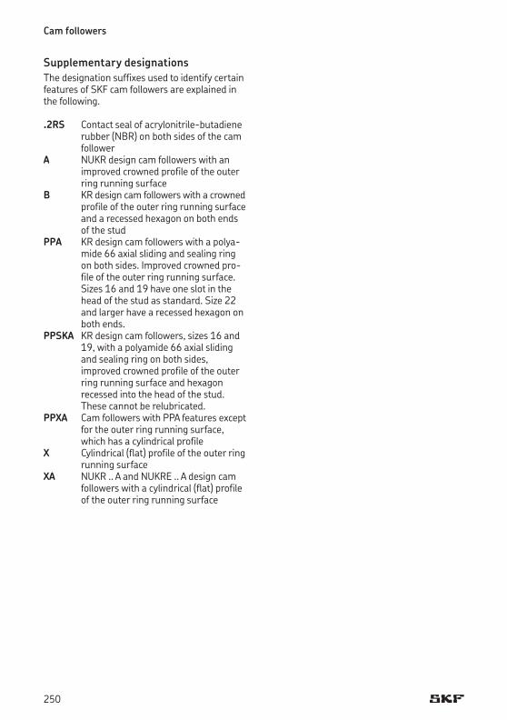
Cam followers
Supplementary designationsThe designation suffixes used to identify certain features of SKF cam followers are explained in the following.
.2RS Contact seal of acrylonitrile-butadiene rubber (NBR) on both sides of the cam follower
A NUKR design cam followers with an improved crowned profile of the outer ring running surface
B KR design cam followers with a crowned profile of the outer ring running surface and a recessed hexagon on both ends of the stud
PPA KR design cam followers with a polya-mide 66 axial sliding and sealing ring on both sides. Improved crowned pro-file of the outer ring running surface. Sizes 16 and 19 have one slot in the head of the stud as standard. Size 22 and larger have a recessed hexagon on both ends.
PPSKA KR design cam followers, sizes 16 and 19, with a polyamide 66 axial sliding and sealing ring on both sides, improved crowned profile of the outer ring running surface and hexagon recessed into the head of the stud. These cannot be relubricated.
PPXA Cam followers with PPA features except for the outer ring running surface, which has a cylindrical profile
X Cylindrical (flat) profile of the outer ring running surface
XA NUKR .. A and NUKRE .. A design cam followers with a cylindrical (flat) profile of the outer ring running surface
250

251
9
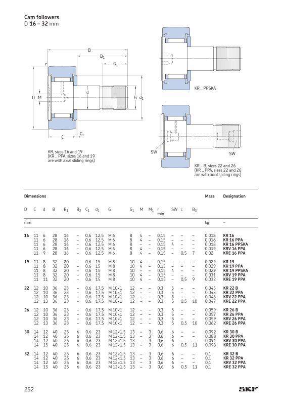
16 11 6 28 16 – 0,6 12,5 M 6 8 4 – 0,15 – – – 0,018 KR 16 11 6 28 16 – 0,6 12,5 M 6 8 4 – 0,15 – – – 0,018 KR 16 PPA 11 6 28 16 – 0,6 12,5 M 6 8 – – 0,15 4 – – 0,018 KR 16 PPSKA 11 6 28 16 – 0,6 12,5 M 6 8 4 – 0,15 – – – 0,019 KRV 16 PPA 11 9 28 16 – 0,6 12,5 M 6 8 4 – 0,15 – 0,5 7 0,02 KRE 16 PPA 19 11 8 32 20 – 0,6 15 M 8 10 4 – 0,15 – – – 0,029 KR 19 11 8 32 20 – 0,6 15 M 8 10 4 – 0,15 – – – 0,029 KR 19 PPA 11 8 32 20 – 0,6 15 M 8 10 – – 0,15 4 – – 0,029 KR 19 PPSKA 11 8 32 20 – 0,6 15 M 8 10 4 – 0,15 – – – 0,031 KRV 19 PPA 11 11 32 20 – 0,6 15 M 8 10 4 – 0,15 – 0,5 9 0,032 KRE 19 PPA 22 12 10 36 23 – 0,6 17,5 M 10¥1 12 – – 0,3 5 – – 0,045 KR 22 B 12 10 36 23 – 0,6 17,5 M 10¥1 12 – – 0,3 5 – – 0,043 KR 22 PPA 12 10 36 23 – 0,6 17,5 M 10¥1 12 – – 0,3 5 – – 0,045 KRV 22 PPA 12 13 36 23 – 0,6 17,5 M 10¥1 12 – – 0,3 5 0,5 10 0,047 KRE 22 PPA 26 12 10 36 23 – 0,6 17,5 M 10¥1 12 – – 0,3 5 – – 0,059 KR 26 B 12 10 36 23 – 0,6 17,5 M 10¥1 12 – – 0,3 5 – – 0,057 KR 26 PPA 12 10 36 23 – 0,6 17,5 M 10¥1 12 – – 0,3 5 – – 0,059 KRV 26 PPA 12 13 36 23 – 0,6 17,5 M 10¥1 12 – – 0,3 5 0,5 10 0,062 KRE 26 PPA 30 14 12 40 25 6 0,6 23 M 12¥1.5 13 – 3 0,6 6 – – 0,092 KR 30 B 14 12 40 25 6 0,6 23 M 12¥1.5 13 – 3 0,6 6 – – 0,088 KR 30 PPA 14 12 40 25 6 0,6 23 M 12¥1.5 13 – 3 0,6 6 – – 0,091 KRV 30 PPA 14 15 40 25 6 0,6 23 M 12¥1.5 13 – 3 0,6 6 0,5 11 0,093 KRE 30 PPA 32 14 12 40 25 6 0,6 23 M 12¥1.5 13 – 3 0,6 6 – – 0,1 KR 32 B 14 12 40 25 6 0,6 23 M 12¥1.5 13 – 3 0,6 6 – – 0,1 KR 32 PPA 14 12 40 25 6 0,6 23 M 12¥1.5 13 – 3 0,6 6 – – 0,1 KRV 32 PPA 14 15 40 25 6 0,6 23 M 12¥1.5 13 – 3 0,6 6 0,5 11 0,1 KRE 32 PPA
Cam followersD 16 – 32 mm
Dimensions Mass Designation D C d B B1 B2 C1 d1 G G1 M M1 r SW c B3 min
mm kg –
KR, sizes 16 and 19(KR .. PPA, sizes 16 and 19 are with axial sliding rings)
D
B
G1
B1r
G
C1C
dd1M
KR .. PPSKA
SWSW
KR .. B, sizes 22 and 26(KR .. PPA, sizes 22 and 26 are with axial sliding rings)
252
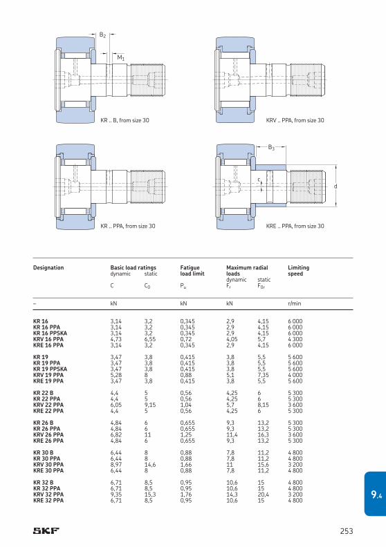
KR 16 3,14 3,2 0,345 2,9 4,15 6 000KR 16 PPA 3,14 3,2 0,345 2,9 4,15 6 000KR 16 PPSKA 3,14 3,2 0,345 2,9 4,15 6 000KRV 16 PPA 4,73 6,55 0,72 4,05 5,7 4 300KRE 16 PPA 3,14 3,2 0,345 2,9 4,15 6 000
KR 19 3,47 3,8 0,415 3,8 5,5 5 600KR 19 PPA 3,47 3,8 0,415 3,8 5,5 5 600KR 19 PPSKA 3,47 3,8 0,415 3,8 5,5 5 600KRV 19 PPA 5,28 8 0,88 5,1 7,35 4 000KRE 19 PPA 3,47 3,8 0,415 3,8 5,5 5 600
KR 22 B 4,4 5 0,56 4,25 6 5 300KR 22 PPA 4,4 5 0,56 4,25 6 5 300KRV 22 PPA 6,05 9,15 1,04 5,7 8,15 3 600KRE 22 PPA 4,4 5 0,56 4,25 6 5 300
KR 26 B 4,84 6 0,655 9,3 13,2 5 300KR 26 PPA 4,84 6 0,655 9,3 13,2 5 300KRV 26 PPA 6,82 11 1,25 11,4 16,3 3 600KRE 26 PPA 4,84 6 0,655 9,3 13,2 5 300
KR 30 B 6,44 8 0,88 7,8 11,2 4 800KR 30 PPA 6,44 8 0,88 7,8 11,2 4 800KRV 30 PPA 8,97 14,6 1,66 11 15,6 3 200KRE 30 PPA 6,44 8 0,88 7,8 11,2 4 800
KR 32 B 6,71 8,5 0,95 10,6 15 4 800KR 32 PPA 6,71 8,5 0,95 10,6 15 4 800KRV 32 PPA 9,35 15,3 1,76 14,3 20,4 3 200KRE 32 PPA 6,71 8,5 0,95 10,6 15 4 800
Designation Basic load ratings Fatigue Maximum radial Limiting dynamic static load limit loads speed dynamic static C C0 Pu Fr F0r
– kN kN kN r/min
M1
B2
KR .. B, from size 30
KR .. PPA, from size 30
KRV .. PPA, from size 30
dc
B3
KRE .. PPA, from size 30
253
9.4
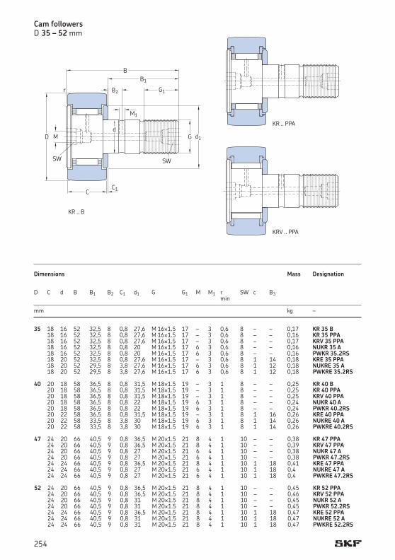
35 18 16 52 32,5 8 0,8 27,6 M 16¥1.5 17 – 3 0,6 8 – – 0,17 KR 35 B 18 16 52 32,5 8 0,8 27,6 M 16¥1.5 17 – 3 0,6 8 – – 0,16 KR 35 PPA 18 16 52 32,5 8 0,8 27,6 M 16¥1.5 17 – 3 0,6 8 – – 0,17 KRV 35 PPA 18 16 52 32,5 8 0,8 20 M 16¥1.5 17 6 3 0,6 8 – – 0,16 NUKR 35 A 18 16 52 32,5 8 0,8 20 M 16¥1.5 17 6 3 0,6 8 – – 0,16 PWKR 35.2RS 18 20 52 32,5 8 0,8 27,6 M 16¥1.5 17 – 3 0,6 8 1 14 0,18 KRE 35 PPA 18 20 52 29,5 8 3,8 27,6 M 16¥1.5 17 6 3 0,6 8 1 12 0,18 NUKRE 35 A 18 20 52 29,5 8 3,8 27,6 M 16¥1.5 17 6 3 0,6 8 1 12 0,18 PWKRE 35.2RS 40 20 18 58 36,5 8 0,8 31,5 M 18¥1.5 19 – 3 1 8 – – 0,25 KR 40 B 20 18 58 36,5 8 0,8 31,5 M 18¥1.5 19 – 3 1 8 – – 0,25 KR 40 PPA 20 18 58 36,5 8 0,8 31,5 M 18¥1.5 19 – 3 1 8 – – 0,25 KRV 40 PPA 20 18 58 36,5 8 0,8 22 M 18¥1.5 19 6 3 1 8 – – 0,24 NUKR 40 A 20 18 58 36,5 8 0,8 22 M 18¥1.5 19 6 3 1 8 – – 0,24 PWKR 40.2RS 20 22 58 36,5 8 0,8 31,5 M 18¥1.5 19 – 3 1 8 1 16 0,26 KRE 40 PPA 20 22 58 33,5 8 3,8 30 M 18¥1.5 19 6 3 1 8 1 14 0,26 NUKRE 40 A 20 22 58 33,5 8 3,8 30 M 18¥1.5 19 6 3 1 8 1 14 0,26 PWKRE 40.2RS 47 24 20 66 40,5 9 0,8 36,5 M 20¥1.5 21 8 4 1 10 – – 0,38 KR 47 PPA 24 20 66 40,5 9 0,8 36,5 M 20¥1.5 21 8 4 1 10 – – 0,39 KRV 47 PPA 24 20 66 40,5 9 0,8 27 M 20¥1.5 21 6 4 1 10 – – 0,38 NUKR 47 A 24 20 66 40,5 9 0,8 27 M 20¥1.5 21 6 4 1 10 – – 0,38 PWKR 47.2RS 24 24 66 40,5 9 0,8 36,5 M 20¥1.5 21 8 4 1 10 1 18 0,41 KRE 47 PPA 24 24 66 40,5 9 0,8 27 M 20¥1.5 21 6 4 1 10 1 18 0,4 NUKRE 47 A 24 24 66 40,5 9 0,8 27 M 20¥1.5 21 6 4 1 10 1 18 0,4 PWKRE 47.2RS 52 24 20 66 40,5 9 0,8 36,5 M 20¥1.5 21 8 4 1 10 – – 0,45 KR 52 PPA 24 20 66 40,5 9 0,8 36,5 M 20¥1.5 21 8 4 1 10 – – 0,46 KRV 52 PPA 24 20 66 40,5 9 0,8 31 M 20¥1.5 21 8 4 1 10 – – 0,45 NUKR 52 A 24 20 66 40,5 9 0,8 31 M 20¥1.5 21 8 4 1 10 – – 0,45 PWKR 52.2RS 24 24 66 40,5 9 0,8 36,5 M 20¥1.5 21 8 4 1 10 1 18 0,47 KRE 52 PPA 24 24 66 40,5 9 0,8 31 M 20¥1.5 21 8 4 1 10 1 18 0,47 NUKRE 52 A 24 24 66 40,5 9 0,8 31 M 20¥1.5 21 8 4 1 10 1 18 0,47 PWKRE 52.2RS
Dimensions Mass Designation D C d B B1 B2 C1 d1 G G1 M M1 r SW c B3 min
mm kg –
Cam followersD 35 – 52 mm
M1
B2
D
B
G1
B1r
GM
C1C
dd1
SW SW
KR .. B
KR .. PPA
KRV .. PPA
254
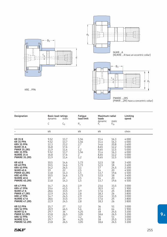
KR 35 B 9,52 13,7 1,56 11,4 16,3 4 000KR 35 PPA 9,52 13,7 1,56 11,4 16,3 4 000KRV 35 PPA 12,3 23,2 2,7 14,6 20,8 2 600NUKR 35 A 16,8 17,6 2 8,65 12,2 5 000PWKR 35.2RS 11,9 11,4 1,2 8,65 12,5 5 000KRE 35 PPA 9,52 13,7 1,56 11,4 16,3 4 000NUKRE 35 A 16,8 17,6 2 8,65 12,2 5 000PWKRE 35.2RS 11,9 11,4 1,2 8,65 12,5 5 000 KR 40 B 10,5 14,6 1,73 12,5 18 3 400KR 40 PPA 10,5 14,6 1,73 12,5 18 3 400KRV 40 PPA 14,2 26,5 3,1 17 24,5 2 200NUKR 40 A 19 22 2,5 14 20 4 500PWKR 40.2RS 13,8 14,3 1,5 13,7 19,6 4 500KRE 40 PPA 10,5 14,6 1,73 12,5 18 3 400NUKRE 40 A 19 22 2,5 14 20 4 500PWKRE 40.2RS 13,8 14,3 1,5 13,7 19,6 4 500 KR 47 PPA 14,7 24,5 2,9 23,6 33,5 3 000KRV 47 PPA 19,4 41,5 5 30,5 43 1 900NUKR 47 A 28,6 33,5 3,9 17,6 25 3 800PWKR 47.2RS 22,9 24,5 2,8 18,3 26 3 800KRE 47 PPA 14,7 24,5 2,9 23,6 33,5 3 000NUKRE 47 A 28,6 33,5 3,9 17,6 25 3 800PWKRE 47.2RS 22,9 24,5 2,8 18,3 26 3 800 KR 52 PPA 15,7 27 3,2 36 51 3 000KRV 52 PPA 20,9 46,5 5,6 45 64 1 900NUKR 52 A 29,7 36 4,25 18 25,5 3 200PWKR 52.2RS 23,8 26,5 3,05 18,6 26,5 3 200KRE 52 PPA 15,7 27 3,2 36 51 3 000NUKRE 52 A 29,7 36 4,25 18 25,5 3 200PWKRE 52.2RS 23,8 26,5 3,05 18,6 26,5 3 200
Designation Basic load ratings Fatigue Maximum radial Limiting dynamic static load limit loads speed dynamic static C C0 Pu Fr F0r
– kN kN kN r/min
B3
d d1c
dc
B3
KRE .. PPA
d1
NUKR .. A(NUKRE .. A have an eccentric collar)
PWKRE ...2RS(PWKR ...2RS have a concentric collar)
255
9.4
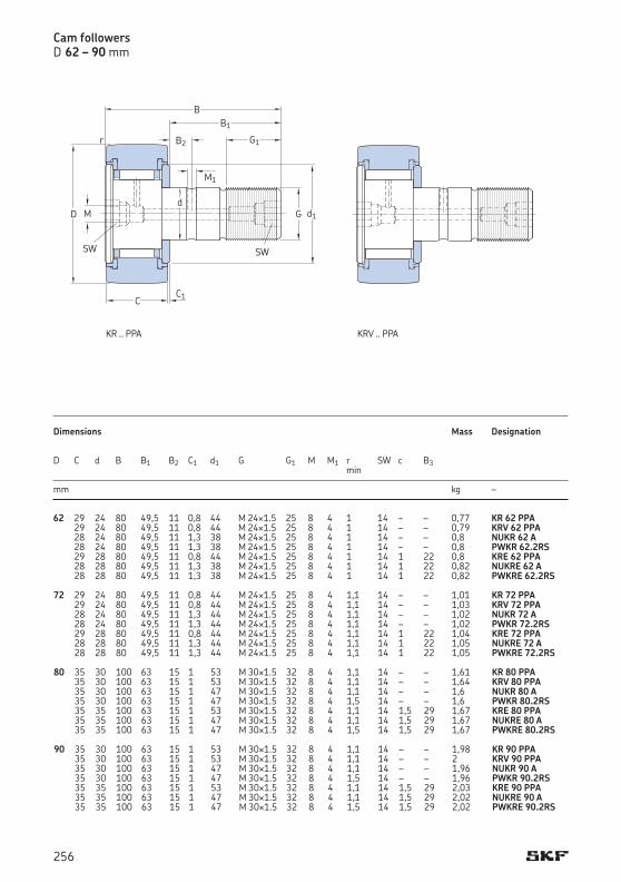
Cam followersD 62 – 90 mm
62 29 24 80 49,5 11 0,8 44 M 24¥1.5 25 8 4 1 14 – – 0,77 KR 62 PPA 29 24 80 49,5 11 0,8 44 M 24¥1.5 25 8 4 1 14 – – 0,79 KRV 62 PPA 28 24 80 49,5 11 1,3 38 M 24¥1.5 25 8 4 1 14 – – 0,8 NUKR 62 A 28 24 80 49,5 11 1,3 38 M 24¥1.5 25 8 4 1 14 – – 0,8 PWKR 62.2RS 29 28 80 49,5 11 0,8 44 M 24¥1.5 25 8 4 1 14 1 22 0,8 KRE 62 PPA 28 28 80 49,5 11 1,3 38 M 24¥1.5 25 8 4 1 14 1 22 0,82 NUKRE 62 A 28 28 80 49,5 11 1,3 38 M 24¥1.5 25 8 4 1 14 1 22 0,82 PWKRE 62.2RS 72 29 24 80 49,5 11 0,8 44 M 24¥1.5 25 8 4 1,1 14 – – 1,01 KR 72 PPA 29 24 80 49,5 11 0,8 44 M 24¥1.5 25 8 4 1,1 14 – – 1,03 KRV 72 PPA 28 24 80 49,5 11 1,3 44 M 24¥1.5 25 8 4 1,1 14 – – 1,02 NUKR 72 A 28 24 80 49,5 11 1,3 44 M 24¥1.5 25 8 4 1,1 14 – – 1,02 PWKR 72.2RS 29 28 80 49,5 11 0,8 44 M 24¥1.5 25 8 4 1,1 14 1 22 1,04 KRE 72 PPA 28 28 80 49,5 11 1,3 44 M 24¥1.5 25 8 4 1,1 14 1 22 1,05 NUKRE 72 A 28 28 80 49,5 11 1,3 44 M 24¥1.5 25 8 4 1,1 14 1 22 1,05 PWKRE 72.2RS 80 35 30 100 63 15 1 53 M 30¥1.5 32 8 4 1,1 14 – – 1,61 KR 80 PPA 35 30 100 63 15 1 53 M 30¥1.5 32 8 4 1,1 14 – – 1,64 KRV 80 PPA 35 30 100 63 15 1 47 M 30¥1.5 32 8 4 1,1 14 – – 1,6 NUKR 80 A 35 30 100 63 15 1 47 M 30¥1.5 32 8 4 1,5 14 – – 1,6 PWKR 80.2RS 35 35 100 63 15 1 53 M 30¥1.5 32 8 4 1,1 14 1,5 29 1,67 KRE 80 PPA 35 35 100 63 15 1 47 M 30¥1.5 32 8 4 1,1 14 1,5 29 1,67 NUKRE 80 A 35 35 100 63 15 1 47 M 30¥1.5 32 8 4 1,5 14 1,5 29 1,67 PWKRE 80.2RS 90 35 30 100 63 15 1 53 M 30¥1.5 32 8 4 1,1 14 – – 1,98 KR 90 PPA 35 30 100 63 15 1 53 M 30¥1.5 32 8 4 1,1 14 – – 2 KRV 90 PPA 35 30 100 63 15 1 47 M 30¥1.5 32 8 4 1,1 14 – – 1,96 NUKR 90 A 35 30 100 63 15 1 47 M 30¥1.5 32 8 4 1,5 14 – – 1,96 PWKR 90.2RS 35 35 100 63 15 1 53 M 30¥1.5 32 8 4 1,1 14 1,5 29 2,03 KRE 90 PPA 35 35 100 63 15 1 47 M 30¥1.5 32 8 4 1,1 14 1,5 29 2,02 NUKRE 90 A 35 35 100 63 15 1 47 M 30¥1.5 32 8 4 1,5 14 1,5 29 2,02 PWKRE 90.2RS
Dimensions Mass Designation D C d B B1 B2 C1 d1 G G1 M M1 r SW c B3 min
mm kg –
D
B
M1
B2 G1
B1r
GM
C1C
dd1
SW SW
KR .. PPA KRV .. PPA
256

KR 62 PPA 24,6 44 5,5 58,5 85 2 400KRV 62 PPA 31,4 72 9 72 102 1 700NUKR 62 A 41,3 48 5,85 25 36 2 600PWKR 62.2RS 31,9 32,5 4,05 20,4 29 2 600KRE 62 PPA 24,6 44 5,5 58,5 85 2 400NUKRE 62 A 41,3 48 5,85 25 36 2 600PWKRE 62.2RS 31,9 32,5 4,05 20,4 29 2 600
KR 72 PPA 26 48 6 100 143 2 400KRV 72 PPA 33 80 9,8 118 170 1 700NUKR 72 A 45,7 58,5 7,1 34,5 50 2 000PWKR 72.2RS 39,6 45 5,6 47,5 68 2 600KRE 72 PPA 26 48 6 100 143 2 400NUKRE 72 A 45,7 58,5 7,1 34,5 50 2 000PWKRE 72.2RS 39,6 45 5,6 47,5 68 2 600
KR 80 PPA 36,9 72 9 106 150 1 800KRV 80 PPA 45,7 114 14 122 176 1 400NUKR 80 A 69,3 86,5 10,8 48 69,5 1 900PWKR 80.2RS 57,2 73,5 9,3 64 91,5 2 000KRE 80 PPA 36,9 72 9 106 150 1 800NUKRE 80 A 69,3 86,5 10,8 48 69,5 1 900PWKRE 80.2RS 57,2 73,5 9,3 64 91,5 2 000
KR 90 PPA 38 76,5 9,5 160 228 1 800KRV 90 PPA 47,3 122 15 183 260 1 400NUKR 90 A 78,1 102 12,7 86,5 125 1 900PWKR 90.2RS 62,7 85 10,8 108 153 2 000KRE 90 PPA 38 76,5 9,5 160 228 1 800NUKRE 90 A 78,1 102 12,7 86,5 125 1 900PWKRE 90.2RS 62,7 85 10,8 108 153 2 000
Designation Basic load ratings Fatigue Maximum radial Limiting dynamic static load limit loads speed dynamic static C C0 Pu Fr F0r
– kN kN kN r/min
B3
d d1c
dc
B3
KRE .. PPA
d1
NUKR .. A(NUKRE .. A have an eccentric collar)
PWKRE ...2RS(PWKR ...2RS have a concentric collar)
257
9.4
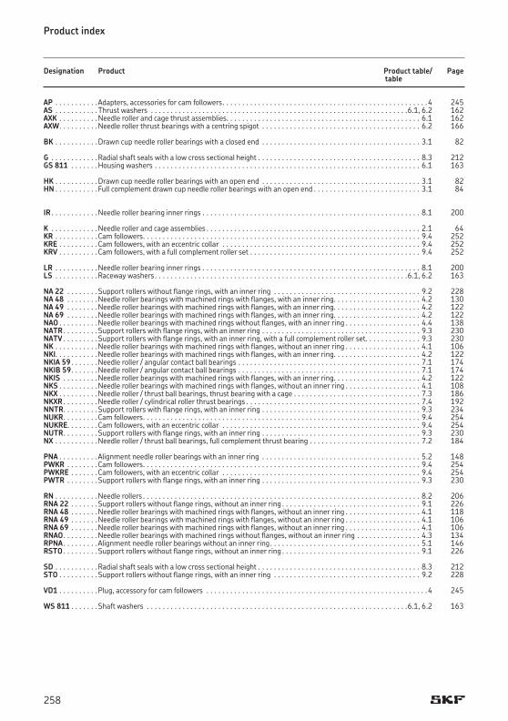
Product index
Designation Product Product table/ Page table
AP . . . . . . . . . . .Adapters, accessories for cam followers . . . . . . . . . . . . . . . . . . . . . . . . . . . . . . . . . . . . . . . . . . . . . . . . . . . .4 245AS . . . . . . . . . . .Thrust washers . . . . . . . . . . . . . . . . . . . . . . . . . . . . . . . . . . . . . . . . . . . . . . . . . . . . . . . . . . . . . . . . .6.1, 6.2 162AXK . . . . . . . . . .Needle roller and cage thrust assemblies . . . . . . . . . . . . . . . . . . . . . . . . . . . . . . . . . . . . . . . . . . . . . . . . . 6.1 162AXW . . . . . . . . . .Needle roller thrust bearings with a centring spigot . . . . . . . . . . . . . . . . . . . . . . . . . . . . . . . . . . . . . . . . 6.2 166
BK . . . . . . . . . . .Drawn cup needle roller bearings with a closed end . . . . . . . . . . . . . . . . . . . . . . . . . . . . . . . . . . . . . . . . 3.1 82
G . . . . . . . . . . . .Radial shaft seals with a low cross sectional height . . . . . . . . . . . . . . . . . . . . . . . . . . . . . . . . . . . . . . . . . 8.3 212GS 811 . . . . . . .Housingwashers . . . . . . . . . . . . . . . . . . . . . . . . . . . . . . . . . . . . . . . . . . . . . . . . . . . . . . . . . . . . . . . . . . . 6.1 163
HK . . . . . . . . . . .Drawn cup needle roller bearings with an open end . . . . . . . . . . . . . . . . . . . . . . . . . . . . . . . . . . . . . . . . 3.1 82HN . . . . . . . . . . . Full complement drawn cup needle roller bearings with an open end . . . . . . . . . . . . . . . . . . . . . . . . . . . 3.1 84
IR . . . . . . . . . . . .Needle roller bearing inner rings . . . . . . . . . . . . . . . . . . . . . . . . . . . . . . . . . . . . . . . . . . . . . . . . . . . . . . . 8.1 200
K . . . . . . . . . . . .Needle roller and cage assemblies . . . . . . . . . . . . . . . . . . . . . . . . . . . . . . . . . . . . . . . . . . . . . . . . . . . . . . 2.1 64KR . . . . . . . . . . .Cam followers . . . . . . . . . . . . . . . . . . . . . . . . . . . . . . . . . . . . . . . . . . . . . . . . . . . . . . . . . . . . . . . . . . . . . . 9.4 252KRE . . . . . . . . . .Cam followers, with an eccentric collar . . . . . . . . . . . . . . . . . . . . . . . . . . . . . . . . . . . . . . . . . . . . . . . . . . 9.4 252KRV . . . . . . . . . .Cam followers, with a full complement roller set . . . . . . . . . . . . . . . . . . . . . . . . . . . . . . . . . . . . . . . . . . . 9.4 252
LR . . . . . . . . . . .Needle roller bearing inner rings . . . . . . . . . . . . . . . . . . . . . . . . . . . . . . . . . . . . . . . . . . . . . . . . . . . . . . . 8.1 200LS . . . . . . . . . . .Raceway washers . . . . . . . . . . . . . . . . . . . . . . . . . . . . . . . . . . . . . . . . . . . . . . . . . . . . . . . . . . . . . . . .6.1, 6.2 163
NA 22 . . . . . . . .Support rollers without flange rings, with an inner ring . . . . . . . . . . . . . . . . . . . . . . . . . . . . . . . . . . . . . 9.2 228NA 48 . . . . . . . .Needle roller bearings with machined rings with flanges, with an inner ring. . . . . . . . . . . . . . . . . . . . . . 4.2 130NA 49 . . . . . . . .Needle roller bearings with machined rings with flanges, with an inner ring. . . . . . . . . . . . . . . . . . . . . . 4.2 122NA 69 . . . . . . . .Needle roller bearings with machined rings with flanges, with an inner ring. . . . . . . . . . . . . . . . . . . . . . 4.2 122NAO . . . . . . . . . .Needle roller bearings with machined rings without flanges, with an inner ring . . . . . . . . . . . . . . . . . . . 4.4 138NATR . . . . . . . . .Support rollers with flange rings, with an inner ring . . . . . . . . . . . . . . . . . . . . . . . . . . . . . . . . . . . . . . . . 9.3 230NATV . . . . . . . . .Support rollers with flange rings, with an inner ring, with a full complement roller set . . . . . . . . . . . . . . 9.3 230NK . . . . . . . . . . .Needle roller bearings with machined rings with flanges, without an inner ring . . . . . . . . . . . . . . . . . . . 4.1 106NKI. . . . . . . . . . .Needle roller bearings with machined rings with flanges, with an inner ring. . . . . . . . . . . . . . . . . . . . . . 4.2 122NKIA 59 . . . . . . .Needle roller / angular contact ball bearings . . . . . . . . . . . . . . . . . . . . . . . . . . . . . . . . . . . . . . . . . . . . . . 7.1 174NKIB 59 . . . . . . .Needle roller / angular contact ball bearings . . . . . . . . . . . . . . . . . . . . . . . . . . . . . . . . . . . . . . . . . . . . . . 7.1 174NKIS . . . . . . . . .Needle roller bearings with machined rings with flanges, with an inner ring. . . . . . . . . . . . . . . . . . . . . . 4.2 122NKS . . . . . . . . . .Needle roller bearings with machined rings with flanges, without an inner ring . . . . . . . . . . . . . . . . . . . 4.1 108NKX . . . . . . . . . .Needle roller / thrust ball bearings, thrust bearing with a cage . . . . . . . . . . . . . . . . . . . . . . . . . . . . . . . . 7.3 186NKXR . . . . . . . . .Needle roller / cylindrical roller thrust bearings . . . . . . . . . . . . . . . . . . . . . . . . . . . . . . . . . . . . . . . . . . . . 7.4 192NNTR . . . . . . . . .Support rollers with flange rings, with an inner ring . . . . . . . . . . . . . . . . . . . . . . . . . . . . . . . . . . . . . . . . 9.3 234NUKR . . . . . . . . .Cam followers . . . . . . . . . . . . . . . . . . . . . . . . . . . . . . . . . . . . . . . . . . . . . . . . . . . . . . . . . . . . . . . . . . . . . . 9.4 254NUKRE. . . . . . . .Cam followers, with an eccentric collar . . . . . . . . . . . . . . . . . . . . . . . . . . . . . . . . . . . . . . . . . . . . . . . . . . 9.4 254NUTR . . . . . . . . .Support rollers with flange rings, with an inner ring . . . . . . . . . . . . . . . . . . . . . . . . . . . . . . . . . . . . . . . . 9.3 230NX . . . . . . . . . . .Needle roller / thrust ball bearings, full complement thrust bearing . . . . . . . . . . . . . . . . . . . . . . . . . . . . 7.2 184
PNA . . . . . . . . . .Alignment needle roller bearings with an inner ring . . . . . . . . . . . . . . . . . . . . . . . . . . . . . . . . . . . . . . . . 5.2 148PWKR . . . . . . . .Cam followers . . . . . . . . . . . . . . . . . . . . . . . . . . . . . . . . . . . . . . . . . . . . . . . . . . . . . . . . . . . . . . . . . . . . . . 9.4 254PWKRE . . . . . . .Cam followers, with an eccentric collar . . . . . . . . . . . . . . . . . . . . . . . . . . . . . . . . . . . . . . . . . . . . . . . . . . 9.4 254PWTR . . . . . . . .Support rollers with flange rings, with an inner ring . . . . . . . . . . . . . . . . . . . . . . . . . . . . . . . . . . . . . . . . 9.3 230
RN . . . . . . . . . . .Needle rollers . . . . . . . . . . . . . . . . . . . . . . . . . . . . . . . . . . . . . . . . . . . . . . . . . . . . . . . . . . . . . . . . . . . . . . 8.2 206RNA 22 . . . . . . .Support rollers without flange rings, without an inner ring . . . . . . . . . . . . . . . . . . . . . . . . . . . . . . . . . . . 9.1 226RNA 48 . . . . . . .Needle roller bearings with machined rings with flanges, without an inner ring . . . . . . . . . . . . . . . . . . . 4.1 118RNA 49 . . . . . . .Needle roller bearings with machined rings with flanges, without an inner ring . . . . . . . . . . . . . . . . . . . 4.1 106RNA 69 . . . . . . .Needle roller bearings with machined rings with flanges, without an inner ring . . . . . . . . . . . . . . . . . . . 4.1 106RNAO . . . . . . . . .Needle roller bearings with machined rings without flanges, without an inner ring . . . . . . . . . . . . . . . . 4.3 134RPNA . . . . . . . . .Alignment needle roller bearings without an inner ring . . . . . . . . . . . . . . . . . . . . . . . . . . . . . . . . . . . . . . 5.1 146RSTO . . . . . . . . .Support rollers without flange rings, without an inner ring . . . . . . . . . . . . . . . . . . . . . . . . . . . . . . . . . . . 9.1 226
SD . . . . . . . . . . .Radial shaft seals with a low cross sectional height . . . . . . . . . . . . . . . . . . . . . . . . . . . . . . . . . . . . . . . . . 8.3 212STO . . . . . . . . . .Support rollers without flange rings, with an inner ring . . . . . . . . . . . . . . . . . . . . . . . . . . . . . . . . . . . . . 9.2 228
VD1 . . . . . . . . . .Plug, accessory for cam followers . . . . . . . . . . . . . . . . . . . . . . . . . . . . . . . . . . . . . . . . . . . . . . . . . . . . . . . .4 245
WS 811 . . . . . . .Shaft washers . . . . . . . . . . . . . . . . . . . . . . . . . . . . . . . . . . . . . . . . . . . . . . . . . . . . . . . . . . . . . . . . . .6.1, 6.2 163
258


skf.com