Embed Size (px)
Citation preview
350 East Plumeria DriveSan Jose, CA 95134USA
November, 2015202-10623-06
Wireless N150 Access Point WN604User Manual
2
Wireless N150 Access Point WN604
SupportThank you for purchasing this NETGEAR product. You can visit www.netgear.com/support to register your product, get help, access the latest downloads and user manuals, and join our community. We recommend that you use only official NETGEAR support resources.
ConformityFor the current EU Declaration of Conformity, visit http://kb.netgear.com/app/answers/detail/a_id/11621.
ComplianceFor regulatory compliance information, visit http://www.netgear.com/about/regulatory.
For the Notification of Compliance statement, visit http://www.netgear.com/images/pdf/Notification_of_Compliance.pdf.
See the regulatory compliance document before connecting the power supply.
Trademarks© NETGEAR, Inc., NETGEAR and the NETGEAR Logo are trademarks of NETGEAR, Inc. Any non-NETGEAR trademarks are used for reference purposes only.
Revision History
Publication Part Number Publish Date Comments
202-10623-06 November 2015 Revised the Support section on this page.
202-10623-05 October 2015 Updated the information on this page and provided a Notification of Compliance link.
202-10623-04 June 2014 Revised the manual.

Contents
Chapter 1 Getting StartedAbout the Access Point . . . . . . . . . . . . . . . . . . . . . . . . . . . . . . . . . . . . . . . . 6Compatible NETGEAR Switches . . . . . . . . . . . . . . . . . . . . . . . . . . . . . . . . .6System Requirements . . . . . . . . . . . . . . . . . . . . . . . . . . . . . . . . . . . . . . . . . 7What’s In the Box . . . . . . . . . . . . . . . . . . . . . . . . . . . . . . . . . . . . . . . . . . . . . 7Hardware Description . . . . . . . . . . . . . . . . . . . . . . . . . . . . . . . . . . . . . . . . . . 7
Front Panel . . . . . . . . . . . . . . . . . . . . . . . . . . . . . . . . . . . . . . . . . . . . . . . . 8Rear Panel . . . . . . . . . . . . . . . . . . . . . . . . . . . . . . . . . . . . . . . . . . . . . . . . 9Side Panel . . . . . . . . . . . . . . . . . . . . . . . . . . . . . . . . . . . . . . . . . . . . . . . 10Product Label . . . . . . . . . . . . . . . . . . . . . . . . . . . . . . . . . . . . . . . . . . . . . 10
Chapter 2 Installation and Basic ConfigurationLog In to the Access Point . . . . . . . . . . . . . . . . . . . . . . . . . . . . . . . . . . . . . 12Install the Access Point . . . . . . . . . . . . . . . . . . . . . . . . . . . . . . . . . . . . . . . 13Configure the System Settings for Your Location. . . . . . . . . . . . . . . . . . . .13Set the Time . . . . . . . . . . . . . . . . . . . . . . . . . . . . . . . . . . . . . . . . . . . . . . . . 15Set Basic IP Options. . . . . . . . . . . . . . . . . . . . . . . . . . . . . . . . . . . . . . . . . . 15Configure Wireless Access. . . . . . . . . . . . . . . . . . . . . . . . . . . . . . . . . . . . . 17Deploy the Access Point. . . . . . . . . . . . . . . . . . . . . . . . . . . . . . . . . . . . . . . 17
Verify Wireless Connectivity . . . . . . . . . . . . . . . . . . . . . . . . . . . . . . . . . .18Wireless Equipment Placement and Range Guidelines . . . . . . . . . . . . .18
Wireless Settings . . . . . . . . . . . . . . . . . . . . . . . . . . . . . . . . . . . . . . . . . . . . 19Wireless Settings Screen Fields. . . . . . . . . . . . . . . . . . . . . . . . . . . . . . .20
Configure Basic QoS Settings . . . . . . . . . . . . . . . . . . . . . . . . . . . . . . . . . .21Set Up and Test Basic Wireless Connectivity . . . . . . . . . . . . . . . . . . . . . .22
Chapter 3 Configure SecuritySecurity Profiles . . . . . . . . . . . . . . . . . . . . . . . . . . . . . . . . . . . . . . . . . . . . . 25
Edit Security Profile Screen Fields . . . . . . . . . . . . . . . . . . . . . . . . . . . . .25Wireless Security Options . . . . . . . . . . . . . . . . . . . . . . . . . . . . . . . . . . . . . 27Manually Configure Security. . . . . . . . . . . . . . . . . . . . . . . . . . . . . . . . . . . . 28
Configure WPA2, or WPA2 + WPA, or WPA . . . . . . . . . . . . . . . . . . . . .28Configure WEP. . . . . . . . . . . . . . . . . . . . . . . . . . . . . . . . . . . . . . . . . . . . 29
Wi-Fi Protected Setup (WPS). . . . . . . . . . . . . . . . . . . . . . . . . . . . . . . . . . . 30Use WPS to Add a Client to the Wireless Network . . . . . . . . . . . . . . . .31
Restrict Wireless Access by MAC Address . . . . . . . . . . . . . . . . . . . . . . . .33
3
Wireless N150 Access Point WN604
Chapter 4 ManagementUpgrade the Wireless Access Point Firmware . . . . . . . . . . . . . . . . . . . . . . 35Configuration File Management . . . . . . . . . . . . . . . . . . . . . . . . . . . . . . . . . 36Change the Administrator Password . . . . . . . . . . . . . . . . . . . . . . . . . . . . . 38Enable the SysLog Server . . . . . . . . . . . . . . . . . . . . . . . . . . . . . . . . . . . . . 39Activity Log . . . . . . . . . . . . . . . . . . . . . . . . . . . . . . . . . . . . . . . . . . . . . . . . . 40View Summary Information . . . . . . . . . . . . . . . . . . . . . . . . . . . . . . . . . . . . 40
System Screen Fields. . . . . . . . . . . . . . . . . . . . . . . . . . . . . . . . . . . . . . . 41Network Traffic Statistics . . . . . . . . . . . . . . . . . . . . . . . . . . . . . . . . . . . . . . 42
Statistic Screen Fields . . . . . . . . . . . . . . . . . . . . . . . . . . . . . . . . . . . . . . 42Available Wireless Station Statistics . . . . . . . . . . . . . . . . . . . . . . . . . . . . . 43
Chapter 5 Advanced ConfigurationSchedule the Wireless Radio . . . . . . . . . . . . . . . . . . . . . . . . . . . . . . . . . . . 45Advanced Wireless Settings. . . . . . . . . . . . . . . . . . . . . . . . . . . . . . . . . . . . 45
Advanced Wireless Settings Screen Fields . . . . . . . . . . . . . . . . . . . . . . 46Advanced QoS Settings . . . . . . . . . . . . . . . . . . . . . . . . . . . . . . . . . . . . . . . 47Enable Wireless Bridging . . . . . . . . . . . . . . . . . . . . . . . . . . . . . . . . . . . . . . 49
Configure a Point-to-Point Bridge. . . . . . . . . . . . . . . . . . . . . . . . . . . . . . 51Configure a Point-to-Multi-Point Wireless Bridge . . . . . . . . . . . . . . . . . . 52
Chapter 6 TroubleshootingTroubleshooting with the LEDs . . . . . . . . . . . . . . . . . . . . . . . . . . . . . . . . . 55
All LEDs Are Off . . . . . . . . . . . . . . . . . . . . . . . . . . . . . . . . . . . . . . . . . . . 55WiFi LED Is Off. . . . . . . . . . . . . . . . . . . . . . . . . . . . . . . . . . . . . . . . . . . . 55LAN LED Is Off . . . . . . . . . . . . . . . . . . . . . . . . . . . . . . . . . . . . . . . . . . . . 56
Cannot Access the Internet or the LAN Wirelessly . . . . . . . . . . . . . . . . . . 56Cannot Connect to the Access Point to Configure It . . . . . . . . . . . . . . . . . 56Time-Out Error . . . . . . . . . . . . . . . . . . . . . . . . . . . . . . . . . . . . . . . . . . . . . . 57
Appendix A Supplemental InformationFactory Default Settings . . . . . . . . . . . . . . . . . . . . . . . . . . . . . . . . . . . . . . . 59Technical Specifications. . . . . . . . . . . . . . . . . . . . . . . . . . . . . . . . . . . . . . . 61
4

1
1. Getting StartedThis chapter covers the following topics:
• About the Access Point • Compatible NETGEAR Switches • System Requirements • What’s In the Box • Hardware Description
Note: For more information about the topics covered in this manual, visit the support website at http://support.netgear.com.
5

Wireless N150 Access Point WN604
About the Access Point
The Wireless N150 Access Point WN604 is the basic building block of a wireless LAN infrastructure. It provides connectivity between Ethernet wired networks and radio-equipped wireless notebook systems, desktop systems, print servers, and other devices.
The access point provides wireless connectivity to multiple wireless network devices within a fixed range or area of coverage—interacting with a wireless network interface card (NIC) through an antenna. Typically, an individual in-building access point provides a maximum connectivity area with about a 500-foot radius. Consequently, the access point can support a small group of users in a range of several hundred feet. Most access points can handle between 10 and 30 users simultaneously per radio.
The access point acts as a bridge between the wired LAN and wireless clients. Connecting multiple access points through a wired Ethernet backbone can extend the wireless network coverage. As a mobile computing device moves out of the range of one access point, it moves into the range of another. As a result, wireless clients can freely roam from one access point to another and still maintain seamless connection to the network.
Compatible NETGEAR Switches
For a list of compatible products from other manufacturers, see the Wireless Ethernet Compatibility Alliance website (WECA; see www.wi-fi.net).
The following NETGEAR switches work with the WN604 Wireless Access Point:
• FS108P - ProSafe™ 8 Port 10/100 Switch with 4 Port PoE• FS116P ProSafe 16 Port 10/100 Desktop Switch with 8 Port PoE• FS726TP - ProSafe 24 Port 10/100 Smart Switch with 2 Gigabit Ports and 12 Port PoE• FS728TP - ProSafe 24+4 10/100 Smart Switch with full PoE• FS752TPS - ProSafe 48 Port 10/100 Stackable Smart Switch with 4 Gigabit Ports and 24
Port PoE• FSM7328PS - ProSafe 24-port 10/100 L3 Managed Stackable Switch with 24 PoE Ports• FSM7352PS-ProSafe 48 Port 10/100 L3 Managed Stackable Switch with 4 Gigabit Ports
and PoE• GS724TP-ProSafe GS724TP 24-Port Gigabit Smart Switch and PoE • GS748TP-ProSafe GS748TP 48-Port Gigabit Smart Switch and PoE
Getting Started
6

Wireless N150 Access Point WN604
System Requirements
Before installing the access point, make sure your system meets these requirements:
• A 10/100 Mbps LAN device such as a hub or switch• The Category 5 UTP straight through Ethernet cable with RJ-45 connector included in the
package, or one like it• A 100–240 V, 50–60 Hz AC power source• A web browser for configuration such as Microsoft Internet Explorer 6.0 or later, or Mozilla
3.0 or later• At least one computer with the TCP/IP protocol installed• 802.11b/g/n-compliant devices
What’s In the Box
The package contains the following:
• Wireless N150 Access Point WN604• Ethernet cable• Power adapter• Vertical stand feet (2)• Installation Guide• Resource CD
Contact your reseller or customer support in your area if there are any missing or damaged parts. Keep the original packing materials, and use the packing materials to repack the access point if you need to return it for repair. To qualify for product updates and product warranty registrations, we encourage you to register on the NETGEAR website at: www.NETGEAR.com.
Hardware Description
This section describes the front, rear, and side hardware functions of the access point.
Getting Started
7
Wireless N150 Access Point WN604
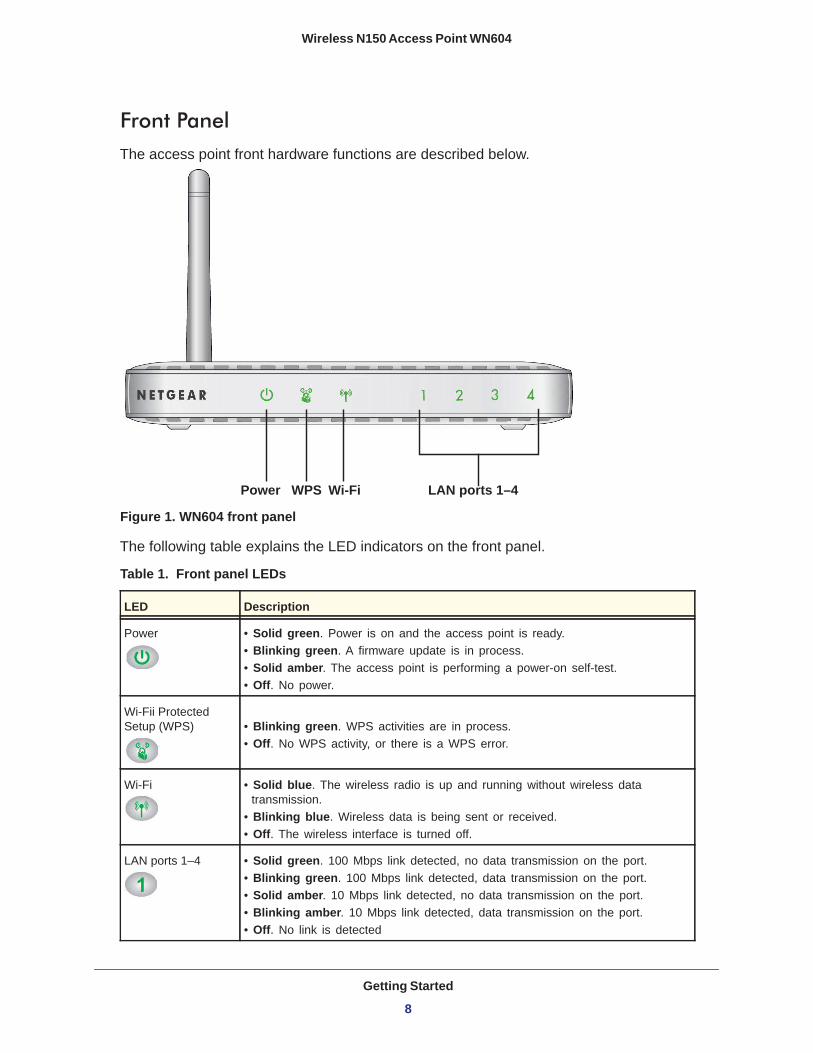
Front PanelThe access point front hardware functions are described below.
Figure 1. WN604 front panel
The following table explains the LED indicators on the front panel.
Table 1. Front panel LEDs
LED Description
Power • Solid green. Power is on and the access point is ready.• Blinking green. A firmware update is in process.• Solid amber. The access point is performing a power-on self-test.• Off. No power.
Wi-Fii Protected Setup (WPS) • Blinking green. WPS activities are in process.
• Off. No WPS activity, or there is a WPS error.
Wi-Fi • Solid blue. The wireless radio is up and running without wireless data transmission.
• Blinking blue. Wireless data is being sent or received.• Off. The wireless interface is turned off.
LAN ports 1–4 • Solid green. 100 Mbps link detected, no data transmission on the port.• Blinking green. 100 Mbps link detected, data transmission on the port.• Solid amber. 10 Mbps link detected, no data transmission on the port.• Blinking amber. 10 Mbps link detected, data transmission on the port.• Off. No link is detected
Power Wi-FiWPS LAN ports 1–4
Getting Started
8

Wireless N150 Access Point WN604
Rear Panel
Figure 2. WN604 rear panel
During set up, use an Ethernet RJ-45 port to connect a computer. After initial set up, use an Ethernet port to connect to an Ethernet LAN through a device such as a hub, switch, router, or PoE switch.
The Reset button has two functions:
• Reboot. When pressed and released quickly, the access point restarts.• Reset to Factory Defaults. This button can also be used to clear all data and restore all
settings to the factory default values. See Factory Default Settings on page 59.
PowerPower
LAN ports 1–4 Reset AntennaOn/Off
Getting Started
9
Wireless N150 Access Point WN604
Side Panel
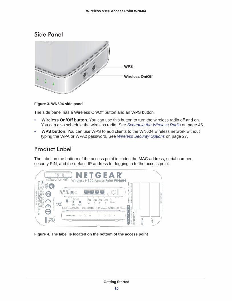
Figure 3. WN604 side panel
The side panel has a Wireless On/Off button and an WPS button.
• Wireless On/Off button. You can use this button to turn the wireless radio off and on. You can also schedule the wireless radio. See Schedule the Wireless Radio on page 45.
• WPS button. You can use WPS to add clients to the WN604 wireless network without typing the WPA or WPA2 password. See Wireless Security Options on page 27.
Product LabelThe label on the bottom of the access point includes the MAC address, serial number, security PIN, and the default IP address for logging in to the access point.
Figure 4. The label is located on the bottom of the access point
Wireless On/Off
WPS
Getting Started
10
2
2. Installation and Basic ConfigurationThis chapter contains the following sections:
• Log In to the Access Point • Install the Access Point • Set the Time • Set Basic IP Options • Configure Wireless Access • Deploy the Access Point • Wireless Settings • Wireless Settings • Configure Basic QoS Settings • Set Up and Test Basic Wireless Connectivity
11

Wireless N150 Access Point WN604
Log In to the Access Point
The access point is set, by default, with the IP address of 192.168.0.100 with DHCP disabled.
To log in to the access point:
1. Prepare a computer with an Ethernet adapter. a. If this computer is part of your network, record its TCP/IP configuration settings. b. Configure the computer with a static IP address of 192.168.0.210 and 255.255.255.0
for the subnet mask.2. Connect an Ethernet cable from the access point to the computer.
3. Power up the access point.a. Connect the power adapter and plug it into an electrical outlet.b. Make sure that the Power On/Off button on the rear panel is in the On position
(pressed in).4. Verify the following:
• The Power LED is on. • The LAN LED is on for the LAN port that is connected to your powered-on computer.• The WiFi LED is blinking.
5. Launch a web browser and enter http://192.168.0.100 in the address field. You are prompted to log in:
6. Type admin in the User name field and password in the Password field, both in lower-case letters, and click Login.
Installation and Basic Configuration
12
Wireless N150 Access Point WN604
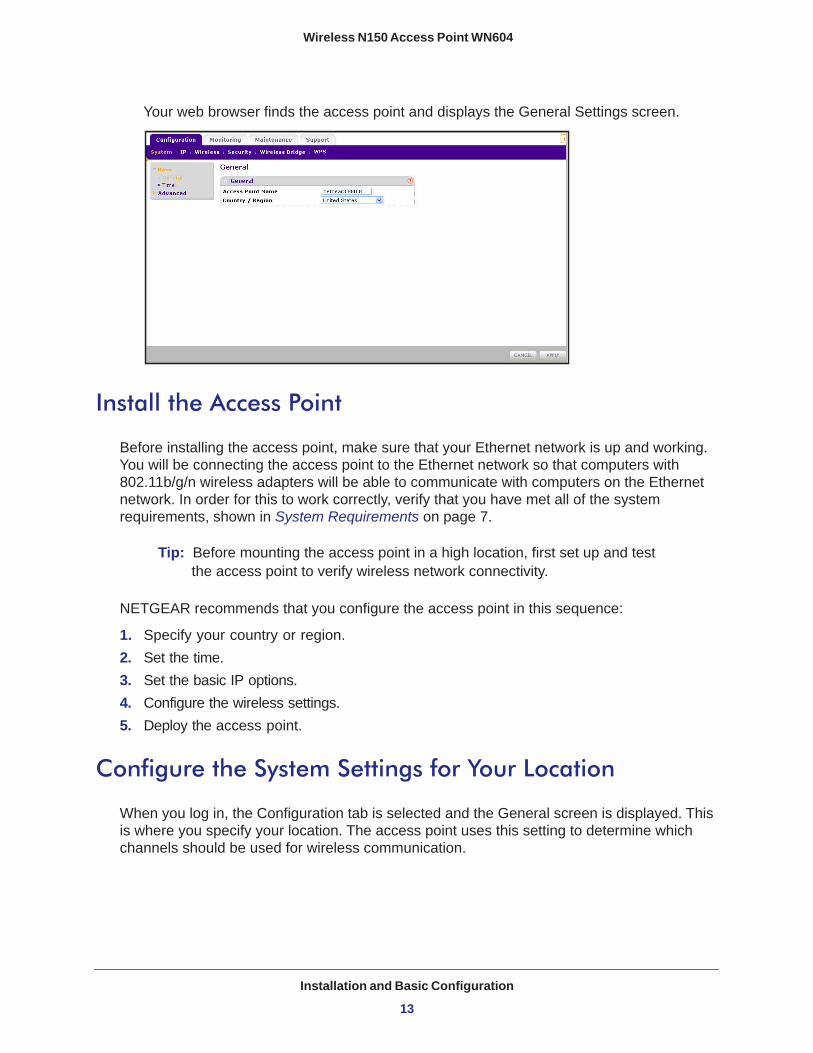
Your web browser finds the access point and displays the General Settings screen.
Install the Access Point
Before installing the access point, make sure that your Ethernet network is up and working. You will be connecting the access point to the Ethernet network so that computers with 802.11b/g/n wireless adapters will be able to communicate with computers on the Ethernet network. In order for this to work correctly, verify that you have met all of the system requirements, shown in System Requirements on page 7.
Tip: Before mounting the access point in a high location, first set up and test the access point to verify wireless network connectivity.
NETGEAR recommends that you configure the access point in this sequence:
1. Specify your country or region.2. Set the time.3. Set the basic IP options.4. Configure the wireless settings.5. Deploy the access point.
Configure the System Settings for Your Location
When you log in, the Configuration tab is selected and the General screen is displayed. This is where you specify your location. The access point uses this setting to determine which channels should be used for wireless communication.
Installation and Basic Configuration
13
Wireless N150 Access Point WN604
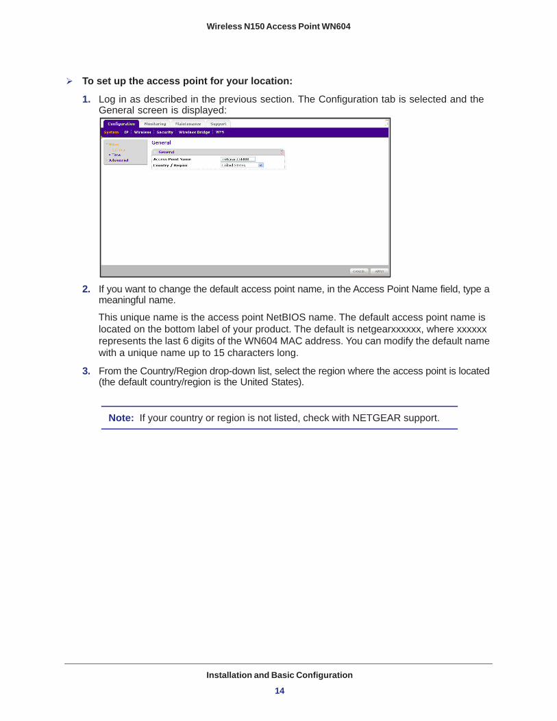
To set up the access point for your location:
1. Log in as described in the previous section. The Configuration tab is selected and the General screen is displayed:
2. If you want to change the default access point name, in the Access Point Name field, type a meaningful name.
This unique name is the access point NetBIOS name. The default access point name is located on the bottom label of your product. The default is netgearxxxxxx, where xxxxxx represents the last 6 digits of the WN604 MAC address. You can modify the default name with a unique name up to 15 characters long.
3. From the Country/Region drop-down list, select the region where the access point is located (the default country/region is the United States).
Note: If your country or region is not listed, check with NETGEAR support.
Installation and Basic Configuration
14
Wireless N150 Access Point WN604
Set the Time
To configure your time settings:
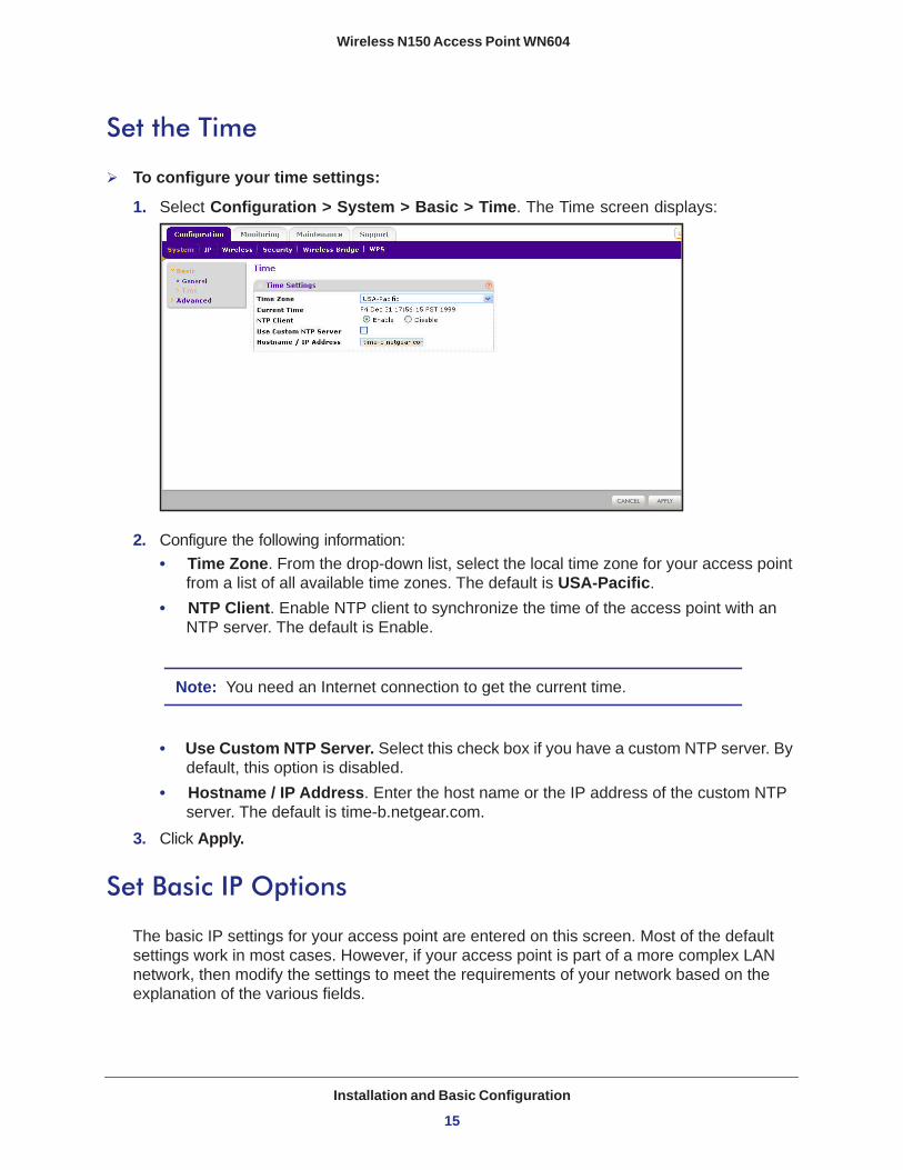
1. Select Configuration > System > Basic > Time. The Time screen displays:
2. Configure the following information:• Time Zone. From the drop-down list, select the local time zone for your access point
from a list of all available time zones. The default is USA-Pacific.• NTP Client. Enable NTP client to synchronize the time of the access point with an
NTP server. The default is Enable.
Note: You need an Internet connection to get the current time.
• Use Custom NTP Server. Select this check box if you have a custom NTP server. By default, this option is disabled.
• Hostname / IP Address. Enter the host name or the IP address of the custom NTP server. The default is time-b.netgear.com.
3. Click Apply.
Set Basic IP Options
The basic IP settings for your access point are entered on this screen. Most of the default settings work in most cases. However, if your access point is part of a more complex LAN network, then modify the settings to meet the requirements of your network based on the explanation of the various fields.
Installation and Basic Configuration
15

Wireless N150 Access Point WN604
To configure the basic IP settings of your access point:
1. Select Configuration > IP > IP Settings. The IP Settings screen displays:
2. Enter the settings for the access point.
DHCP Client. By default, the Dynamic Host Configuration Protocol (DHCP) client is disabled. If you have a DHCP server on your LAN and you enable DHCP, the wireless access point gets its IP address, subnet mask, and default gateway settings automatically from the DHCP server on your network when you connect the access point to your LAN.
IP Address. Enter the IP address of your access point.The default IP address is 192.168.0.100. To change it, enter an unused IP address from the address range used on your LAN; or enable DHCP.
IP Subnet Mask. The access point automatically calculates the subnet mask based on the IP address that you assign. Otherwise, you can use 255.255.255.0 (the default) as the subnet mask.
Default Gateway. Enter the IP address of the gateway for your LAN. For more complex networks, enter the address of the router for the network segment to which the access point is connected.
Primary DNS Servers. This is the address of the primary Domain Name Server used by stations on your LAN.
Secondary DNS Servers. This is the address of the secondary Domain Name Server used by stations on your LAN.
Network Integrity Check. Select this check box to enable the access point to validate that the upstream link is active before allowing wireless associations. If you set this option, you have to ensure that your default gateway is configured.
3. Click Apply to save your basic IP settings.
Installation and Basic Configuration
16
Wireless N150 Access Point WN604
Configure Wireless Access
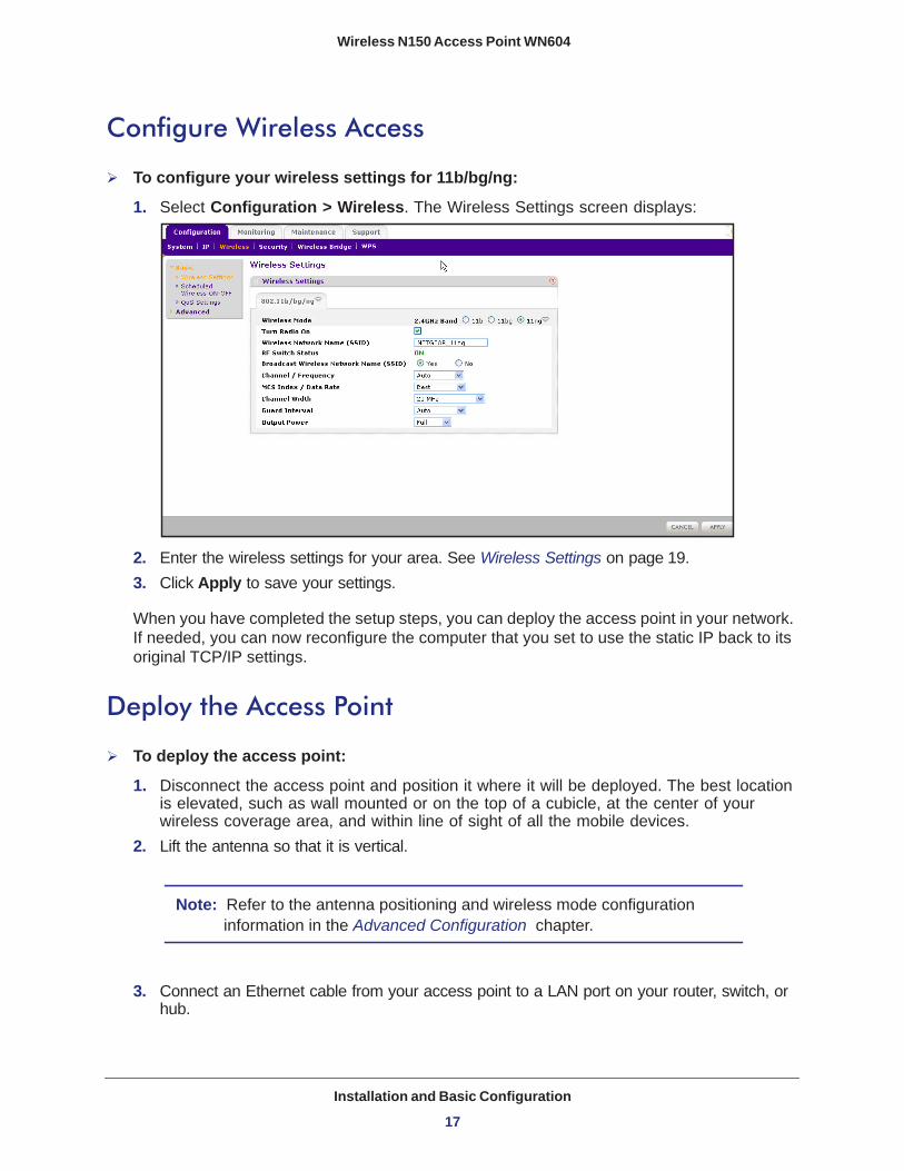
To configure your wireless settings for 11b/bg/ng:
1. Select Configuration > Wireless. The Wireless Settings screen displays:
2. Enter the wireless settings for your area. See Wireless Settings on page 19.3. Click Apply to save your settings.
When you have completed the setup steps, you can deploy the access point in your network. If needed, you can now reconfigure the computer that you set to use the static IP back to its original TCP/IP settings.
Deploy the Access Point
To deploy the access point:
1. Disconnect the access point and position it where it will be deployed. The best location is elevated, such as wall mounted or on the top of a cubicle, at the center of your wireless coverage area, and within line of sight of all the mobile devices.
2. Lift the antenna so that it is vertical.
Note: Refer to the antenna positioning and wireless mode configuration information in the Advanced Configuration chapter.
3. Connect an Ethernet cable from your access point to a LAN port on your router, switch, or hub.
Installation and Basic Configuration
17

Wireless N150 Access Point WN604
Note: By default, the access point is set with the DHCP client disabled. If your network uses dynamic IP addresses, you have to change this setting. To connect to the access point after the DHCP server on your network assigns it a new IP address, enter the access point name into your web browser. The default access point name is netgearxxxxxx, where xxxxxx represents the last 6 bytes of the MAC address. The default name is printed on the bottom label of the access point.
4. Connect the power adapter to the wireless access point and plug the power adapter in to a power outlet. The Power, LAN, and WiFi LEDs should light up.
Verify Wireless ConnectivityUsing a computer with an 802.11b/bg/ng wireless adapter with the correct wireless settings needed to connect to the access point (SSID, WEP/WPA, MAC ACL, etc.), verify connectivity by using a browser such as Mozilla Firefox or Internet Explorer to browse the Internet, or check for file and printer access on your network.
The default SSID for the 802.11b/bg/ng wireless mode is NETGEAR-11g. The SSID of any wireless access adapters has to match the SSID configured in the access point. If they do not match, no wireless connection is made.
Note: If you are unable to connect, see Chapter 6, Troubleshooting.
Wireless Equipment Placement and Range GuidelinesThe operating distance or range of your wireless connection can vary significantly based on the physical placement of the access point. The latency, data throughput performance, and notebook power consumption of wireless adapters also vary depending on your configuration choices.
Note: Failure to follow these guidelines can result in significant performance degradation or inability to wirelessly connect to the WN604. For complete performance specifications, see Appendix A, Supplemental Information.”
Installation and Basic Configuration
18
Wireless N150 Access Point WN604
For best results, place your access point:
• Near the center of the area in which your PCs will operate.• In an elevated location such as a high shelf where the wirelessly connected PCs have
line-of-sight access (even if through walls).• Away from sources of interference, such as PCs, microwaves, and 2.4 GHz cordless
phones.• Away from large metal surfaces.
Putting the antenna in a vertical position provides best side-to-side coverage. Putting the antenna in a horizontal position provides best up-and-down coverage.
The time it takes to establish a wireless connection can vary depending on both your security settings and placement. Some types of security connections can take slightly longer to establish and can consume more battery power on a notebook computer.
Wireless Settings
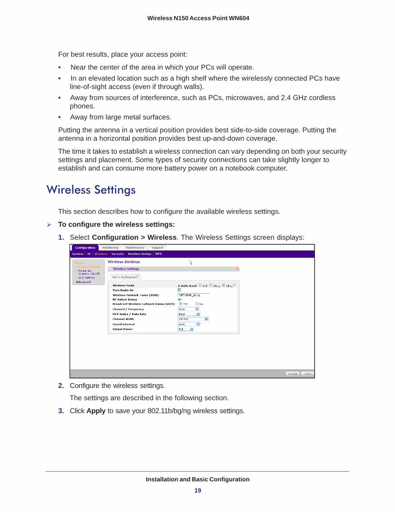
This section describes how to configure the available wireless settings.
To configure the wireless settings:
1. Select Configuration > Wireless. The Wireless Settings screen displays:
2. Configure the wireless settings.
The settings are described in the following section.
3. Click Apply to save your 802.11b/bg/ng wireless settings.
Installation and Basic Configuration
19

Wireless N150 Access Point WN604
Wireless Settings Screen FieldsWireless Mode. Select the desired wireless operating mode. The default is 11ng. The options are:
• 11b. All 802.11b wireless stations can be used. (The 802.11g wireless stations can still be used if they can operate in 802.11b mode.)
• 11bg. Both 802.11b and 802.11g wireless stations are supported.• 11ng. All 11b, 11g, and 11ng wireless stations can be used. This is the default. If you
select this option, then two additional options, Channel Width and Guard Interval, are display.
Note: If you select an option, and some settings on this screen are not available, then you have to select the Turn Radio On radio button to make those settings available.
Turn Radio On. On by default, you can also turn off the radio to disable access through this device. This can be helpful for configuration, network tuning, or troubleshooting activities.
Wireless Network Name (SSID). This is the name of your wireless network. It is set to the default name of NETGEAR_11ng for 802.11b/bg/ng.
RF Switch Status. The WN604 also has an external hardware switch to enable or disable the radio (RF). This field shows its current status. When the RF switch is off, you cannot change wireless parameters.
Broadcast Wireless Network Name (SSID). If you disable broadcast of the SSID, only devices that have the correct SSID can connect. This nullifies the wireless network “discovery” feature of some products such as Windows XP, Vista, and Unix systems, but the data is still fully exposed to a determined snoop using specialized test equipment like wireless sniffers. The default is enabled.
Channel/Frequency. From the drop-down list, select the channel you wish to use on your wireless LAN. The wireless channel in use is between 1 and 11 for United States and Canada, 1 and 13 for Europe and Australia. The default is Auto.
It should not be necessary to change the wireless channel unless you experience interference (shown by lost connections and slow data transfers). Should this happen, you might need to experiment with different channels to see which is the best. Alternatively, you can select the Auto channel option for the AP to intelligently pick the channel with least interference. When selecting or changing channels, some points to bear in mind:
• Access points use a fixed channel. You can select the channel that provides the least interference and best performance. In the USA and Canada, 11 channels are available.
• If you are using multiple access points, it is better if adjacent access points use different channels to reduce interference. The recommended channel spacing between adjacent access points is 5 channels (for example, use channels 1 and 6, or 6 and 11).
Installation and Basic Configuration
20
Wireless N150 Access Point WN604
• Wireless stations normally scan all channels, looking for an access point. If more than one access point can be used, the one with the strongest signal is used. This can only happen only when the various access points are using the same SSID.
MCS Index/Data Rate. From the drop-down list, select the available transmit data rate of the wireless network. Also, depending on the band selected, the set of rates varies. The possible data rates supported are:
• Data rates for channel width = 2 0 MHz and guard interval=short (400 ms): Best, 7.2 Mbps, 14.4 Mbps, 21.7 Mbps, 28.9 Mbps, 43.3 Mbps, 57.8 Mbps, 65 Mbps, 72.2 Mbps.
• Data rates for channel width = 20 MHz and guard interval=long (800 ms): Best, 6.5 Mbps.
• Data rates for channel width = 40 MHz and guard interval=short: Best, 15 Mbps, 30 Mbps, 45 Mbps, 60 Mbps, 90 Mbps, 120 Mbps, 135 Mbps, 150 Mbps.
• Data rates for channel width = 40 MHz and guard interval=long: Best, 13.5 Mbps, 27 Mbps, 40.5 Mbps, 54 Mbps, 81 Mbps, 108Mbps, 121.5 Mbps, 135 Mbps.
Channel Width. From the drop-down list, select the desired channel width.
• 20 MHz. This is the static, legacy mode. It gives the least throughput.• 40 MHz. This is the static, high-throughput mode. Legacy clients cannot connect in this
mode.• 20/40 MHz. This is the dynamic, compatibility mode.
Guard Interval. From the drop-down list, select the desired guard interval. The guard interval protects from interference from other transmissions. The default is Auto.
Output Power. From the drop-down list, select the transmit power of the access point. The options are Full, Half, Quarter, Eighth, and Minimum. Decrease the transmit power if two or more APs are close together and use the same channel frequency. The default is Full. (The transmit power might vary depending on the local regulatory regulations.
Configure Basic QoS Settings
Wireless Multimedia (WMM) is a subset of the 802.11e standard. WMM allows wireless traffic to have a range of priorities, depending on the type of data.
Time-dependent information, such as video or audio, has a higher priority than normal traffic. For WMM to function correctly, wireless clients also have to support WMM.
Installation and Basic Configuration
21

Wireless N150 Access Point WN604
To configure basic wireless QoS settings for 11b/bg/ng and 11a/na:
1. Select Configuration > Wireless > Basic > QoS Settings. The QoS Settings screen displays:
2. Wi-FI Multimedia (WMM) is enabled by default. Select the Disable radio button to disable WMM support.
3. WMM Power Save is enabled by default. Select the Disable radio button to disable WMM power save.
4. Click Apply to save your settings
Set Up and Test Basic Wireless Connectivity
Follow these instructions to set up and test basic wireless connectivity. Once you have established basic wireless connectivity, you can enable security settings appropriate to your needs.
Note: If you are configuring the access point from a wireless computer and you change the SSID, channel, or security profile settings, you will lose your wireless connection when you click Apply. To connect to the wireless network, you have to change the wireless settings of your computer to match the new settings.
To set up and test wireless connectivity:
1. Select Configuration > System. Verify that the correct country/region in which the wireless interface will operate has been selected.
2. Click Apply to save any changes.3. Select Configuration > Wireless.
Installation and Basic Configuration
22

Wireless N150 Access Point WN604
4. Ensure that the auto channel (default) feature is selected for your network. This feature selects a channel that has the least interference.
It should not be necessary to change the wireless channel unless you notice interference problems or are near another wireless access point. Select a channel that is not being used by any other wireless networks within several hundred feet of your access point.
5. Click Apply to save any changes.6. Select Configuration > Security. For initial configuration and testing, the Network
Authentication setting is set to Open System and the default SSID to NETGEAR_11ng. (For more information about configuring a profile, see Security Profiles on page 25.)
Note: The SSID of any station has to match the SSID you configured in the access point. If they do not match, you will not get a wireless connection to the access point.
7. Click Apply to save any changes.8. Configure and test your PCs for wireless connectivity.
Set up the wireless adapters of your PCs to have the same SSID that you configured in the WN604. Check that they have a wireless link and are able to obtain an IP address by DHCP from the WN604.
Once your PCs have basic wireless connectivity, you can configure the advanced wireless security functions.
Installation and Basic Configuration
23
3
3. Configure SecurityThis chapter includes the following sections.
• Security Profiles • Wireless Security Options • Manually Configure Security • Wi-Fi Protected Setup (WPS) • Restrict Wireless Access by MAC Address
24
Wireless N150 Access Point WN604
Security Profiles
Security profiles let you configure unique security settings for each SSID. You can configure only one wireless security profile. You can set up a single security profile for 802.11b/bg/ng, which is the default profile.
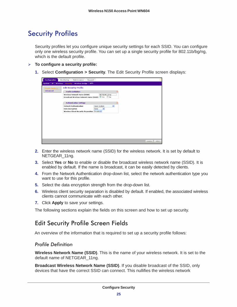
To configure a security profile:
1. Select Configuration > Security. The Edit Security Profile screen displays:
2. Enter the wireless network name (SSID) for the wireless network. It is set by default to NETGEAR_11ng.
3. Select Yes or No to enable or disable the broadcast wireless network name (SSID). It is enabled by default. If the name is broadcast, it can be easily detected by clients.
4. From the Network Authentication drop-down list, select the network authentication type you want to use for this profile.
5. Select the data encryption strength from the drop-down list.6. Wireless client security separation is disabled by default. If enabled, the associated wireless
clients cannot communicate with each other.7. Click Apply to save your settings.
The following sections explain the fields on this screen and how to set up security.
Edit Security Profile Screen FieldsAn overview of the information that is required to set up a security profile follows:
Profile Definition
Wireless Network Name (SSID). This is the name of your wireless network. It is set to the default name of NETGEAR_11ng.
Broadcast Wireless Network Name (SSID). If you disable broadcast of the SSID, only devices that have the correct SSID can connect. This nullifies the wireless network
Configure Security
25

Wireless N150 Access Point WN604
“discovery” feature of some products such as Windows XP, Vista, and Unix systems, but the data is still fully exposed to a determined snoop using specialized test equipment like wireless sniffers. The default is enabled.
Authentication Settings
Network Authentication. The access point is set by default as an open system with no authentication. When setting up network authentication, bear in mind the following:
• If you are using access point mode, then all options are available. In bridge mode some options might be unavailable.
• Legacy adapters might not support WPA or WPA2. Windows XP and Windows 2000 with Service Pack 3 do include the client software that supports WPA. Consult the product documentation for your wireless adapter and WPA or WPA2 client software for instructions on configuring WPA2 settings.
You can configure the access point to use the types of network authentication shown in the following table.
Data Encryption. The available options depend on the Network Authentication setting selected (see Table 2); otherwise, the default is None.
• None. No encryption is used.• 64 bits WEP. Standard WEP encryption, using 40/64 bit encryption.• 128 bits WEP. Standard WEP encryption, using 104/128 bit encryption. • 152 bits WEP. Proprietary mode that works only with other wireless devices that support
this mode. • TKIP. This is the standard encryption method used with WPA and WPA2.
Table 2. Network authentication types
Typea
a. All options are available if using access point mode. In bridge modes some options might beunavailable.
Description
Open System Can be used with WEP encryption or no encryption.
Shared Key This is used with WEP encryption. You enter at least one shared key.
WPA-PSK TKIP or TKIP + AES encryption and enter the WPA passphrase (network key).
WPA2-PSK(WPA2 is a later version of WPA)
Select this only if all clients support WPA2. If selected, you have to use AES or TKIP + AES encryption and enter the WPA passphrase (Network key).
WPA-PSK and WPA2-PSK This selection allows clients to use either WPA (with TKIP) or WPA2 (with AES). If selected, you have to use TKIP + AES encryption and enter the WPA passphrase (Network key).
Configure Security
26

Wireless N150 Access Point WN604
• AES. This is the standard encryption method for WPA2.• TKIP + AES. This setting supports both WPA and WPA2. Broadcast packets use TKIP.
For unicast (point-to-point) transmissions, WPA clients use TKIP, and WPA2 clients use AES.
Passphrase. To use the passphrase to generate the WEP keys, enter a passphrase and click the Generate Keys button. You can also enter the keys directly. These keys have to match the other wireless stations.
Key 1, Key 2, Key 3, Key 4. If using WEP, select the key to be used as the default key. Data transmissions are always encrypted using the default key. The other keys can only be used only to decrypt received data.
WPA Preshared Key Passphrase. If using WPA-PSK or WPA2-PSK, enter the passphrase here. All wireless stations have to use the same passphrase (network key). The network key has to be from 8 to 64 characters in length.
Wireless Client Security Separation. If enabled, the associated wireless clients cannot communicate with each other. (This feature is intended for hotspots and other public access situations.) The default is Disabled.
Wireless Security Options
Your wireless data transmissions can be received well beyond your walls by anyone with a compatible adapter. For this reason, use the security features of your wireless equipment. The access point provides highly effective security features. Deploy the security features appropriate to your needs.
There are several ways you can enhance the security of your wireless network:
• Restrict access based on MAC address. You can restrict access to only trusted PCs so that unknown PCs cannot wirelessly connect to the WN604. MAC address filtering adds an obstacle against unwanted access to your network, but the data broadcast over the wireless link is fully exposed.
• Turn off the broadcast of the wireless network name (SSID). If you disable broadcast of the SSID, only devices that have the correct SSID can connect. This nullifies the wireless network “discovery” feature of some products such as Windows XP, Vista, and Unix systems, but the data is still fully exposed to a determined snoop using specialized test equipment like wireless sniffers.
• Use WPA or WPA-PSK. Wi-Fi Protected Access (WPA) data encryption provides data security. The very strong authentication along with dynamic per frame rekeying of WPA makes it virtually impossible to compromise.
• Use WEP. Wired Equivalent Privacy (WEP) data encryption provides data security. WEP is a legacy security setting. NETGEAR recommends that you use WPA2 or WPA for stronger wireless security.
Configure Security
27
Wireless N150 Access Point WN604
Note: WEP and TKIP provide only legacy rates of operation. So, AES is the recommended solution to use the 802.11n rates and speed.
Manually Configure Security
The following sections explain how to manually configure security.
Note: If you use a wireless computer to change wireless security settings, you will be disconnected when you click Apply. Reconfigure your wireless adapter to match the new settings or access the access point from a wired computer to make any further changes.
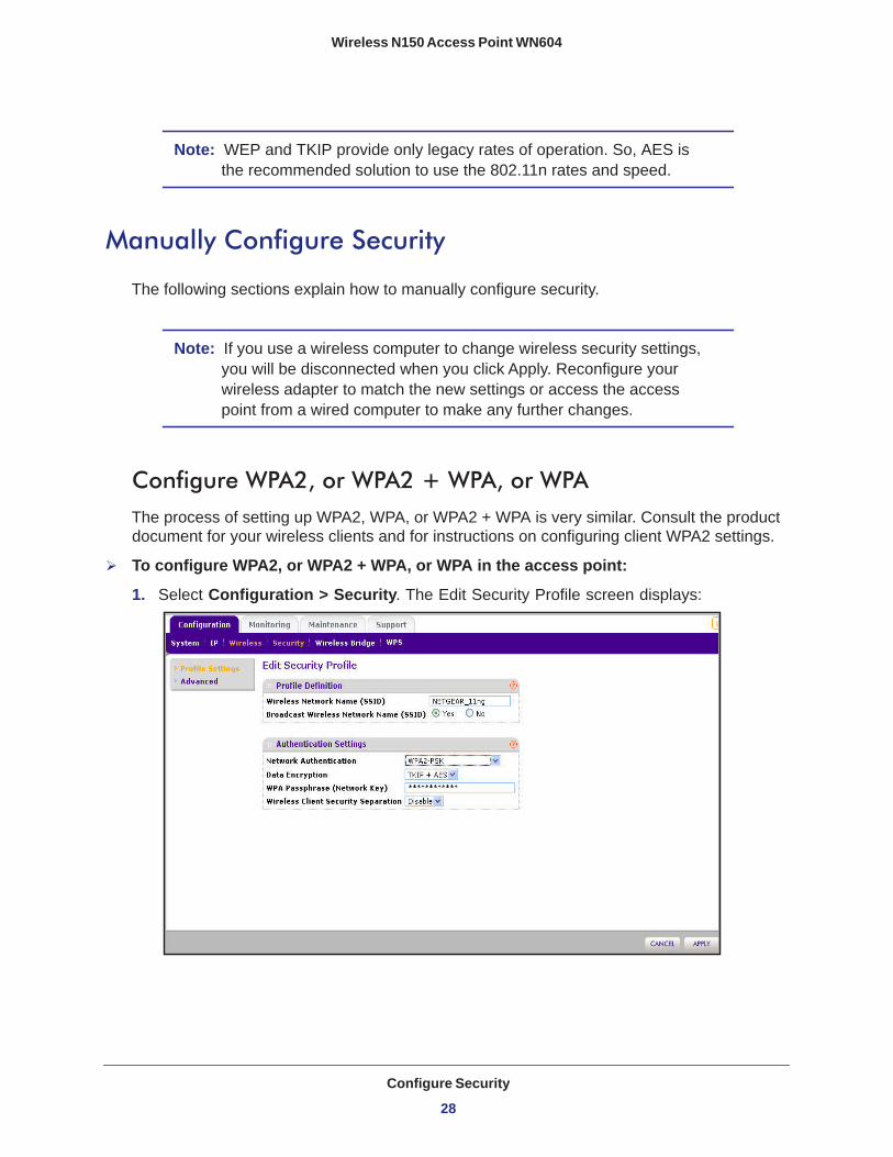
Configure WPA2, or WPA2 + WPA, or WPAThe process of setting up WPA2, WPA, or WPA2 + WPA is very similar. Consult the product document for your wireless clients and for instructions on configuring client WPA2 settings.
To configure WPA2, or WPA2 + WPA, or WPA in the access point:
1. Select Configuration > Security. The Edit Security Profile screen displays:
Configure Security
28
Wireless N150 Access Point WN604
2. From the Network Authentication drop-down list, select the option that you want to use to secure your network. NETGEAR recommends WPA2, but you can select any of the following, depending on whether your client devices support WPA2:• WPA2-PSK. With this setting, only wireless clients that support WPA2 can access the
wireless network. By default, the Data Encryption field is set to AES.• WPA-PSK & WPA2-PSK. Wireless clients using WPA2 or WPA can access the
wireless network. By default, the Data Encryption field is set to TKIP+AES.• WPA-TKIP. Wireless clients using WPA can access the wireless network.
3. In the WPA Passphrase (Network Key) field, enter the password that you want to use to secure the wireless network.
4. Wireless client security separation is disabled by default. If it is enabled, associated wireless clients cannot communicate with each other. (This feature is intended for hotspots and other public access situations.)
5. Click Apply to save your settings.
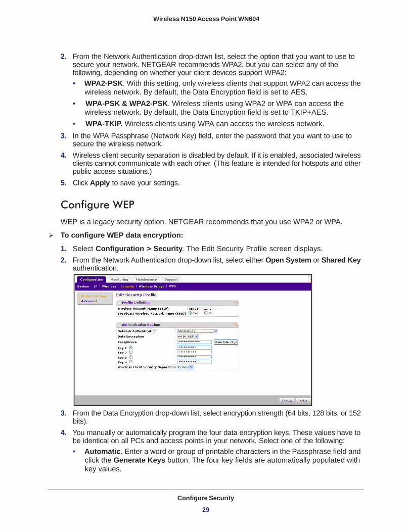
Configure WEPWEP is a legacy security option. NETGEAR recommends that you use WPA2 or WPA.
To configure WEP data encryption:
1. Select Configuration > Security. The Edit Security Profile screen displays.2. From the Network Authentication drop-down list, select either Open System or Shared Key
authentication.
3. From the Data Encryption drop-down list, select encryption strength (64 bits, 128 bits, or 152 bits).
4. You manually or automatically program the four data encryption keys. These values have to be identical on all PCs and access points in your network. Select one of the following:• Automatic. Enter a word or group of printable characters in the Passphrase field and
click the Generate Keys button. The four key fields are automatically populated with key values.
Configure Security
29
Wireless N150 Access Point WN604
• Manual. Enter the number of hexadecimal digits appropriate to the encryption strength: 10 digits for 64-bit, 26 digits for 128–bit, and 32 digits for 152-bit (any combination of 0–9, a-f, or A–F).
5. Select the key to be used as the default key by selecting the radio button. (Data transmissions are always encrypted using the default key.)
6. Wireless client security separation is disabled by default. If it is enabled, associated wireless clients cannot communicate with each other. (This feature is intended for hotspots and other public access situations.
7. Click Apply to save your settings.
Wi-Fi Protected Setup (WPS)
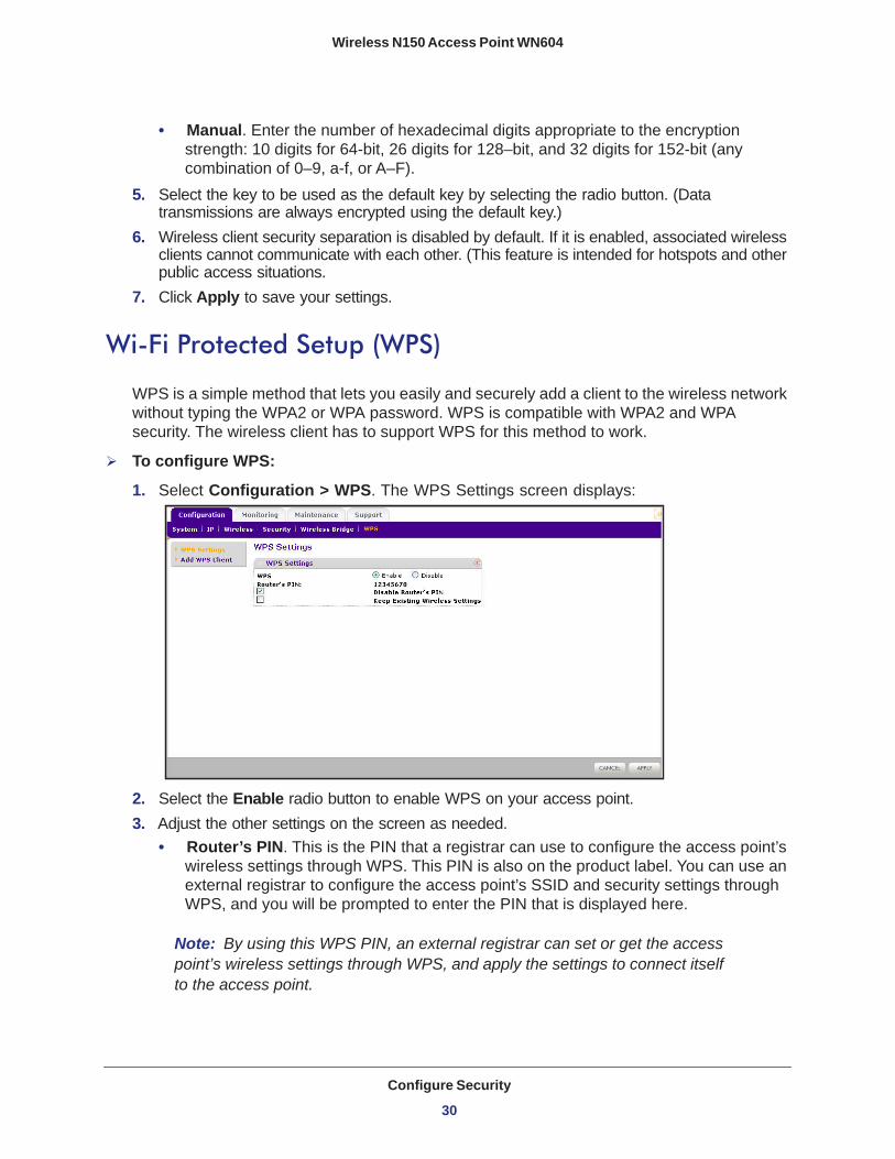
WPS is a simple method that lets you easily and securely add a client to the wireless network without typing the WPA2 or WPA password. WPS is compatible with WPA2 and WPA security. The wireless client has to support WPS for this method to work.
To configure WPS:
1. Select Configuration > WPS. The WPS Settings screen displays:
2. Select the Enable radio button to enable WPS on your access point.3. Adjust the other settings on the screen as needed.
• Router’s PIN. This is the PIN that a registrar can use to configure the access point’s wireless settings through WPS. This PIN is also on the product label. You can use an external registrar to configure the access point’s SSID and security settings through WPS, and you will be prompted to enter the PIN that is displayed here.
Note: By using this WPS PIN, an external registrar can set or get the access point’s wireless settings through WPS, and apply the settings to connect itself to the access point.
Configure Security
30
Wireless N150 Access Point WN604
• Disable Router’s PIN. Select this check box if you want to disable the access point’s PIN. An external registrar can only configure the access point's wireless settings through WPS only when the PIN is enabled. by default, this check box is not selected.
• Keep Existing Wireless Settings. Select this check box if you want to keep the current wireless settings the same when you use WPS to add a client device.
4. Click Apply so that your changes take effect.
Use WPS to Add a Client to the Wireless NetworkWPS is compatible with WPA2 and WPA security. The wireless client has to support WPS for this method to work. Check the documentation that came with the wireless client machine. You can use the WPS button on the side of the access point, or you can log in to the access point and use the Add WPS Client feature.
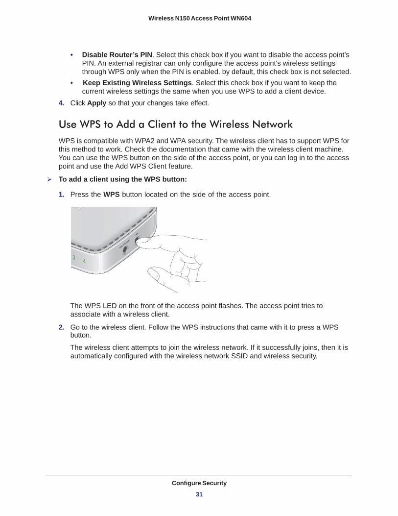
To add a client using the WPS button:
1. Press the WPS button located on the side of the access point.
The WPS LED on the front of the access point flashes. The access point tries to associate with a wireless client.
2. Go to the wireless client. Follow the WPS instructions that came with it to press a WPS button.
The wireless client attempts to join the wireless network. If it successfully joins, then it is automatically configured with the wireless network SSID and wireless security.
Configure Security
31
Wireless N150 Access Point WN604
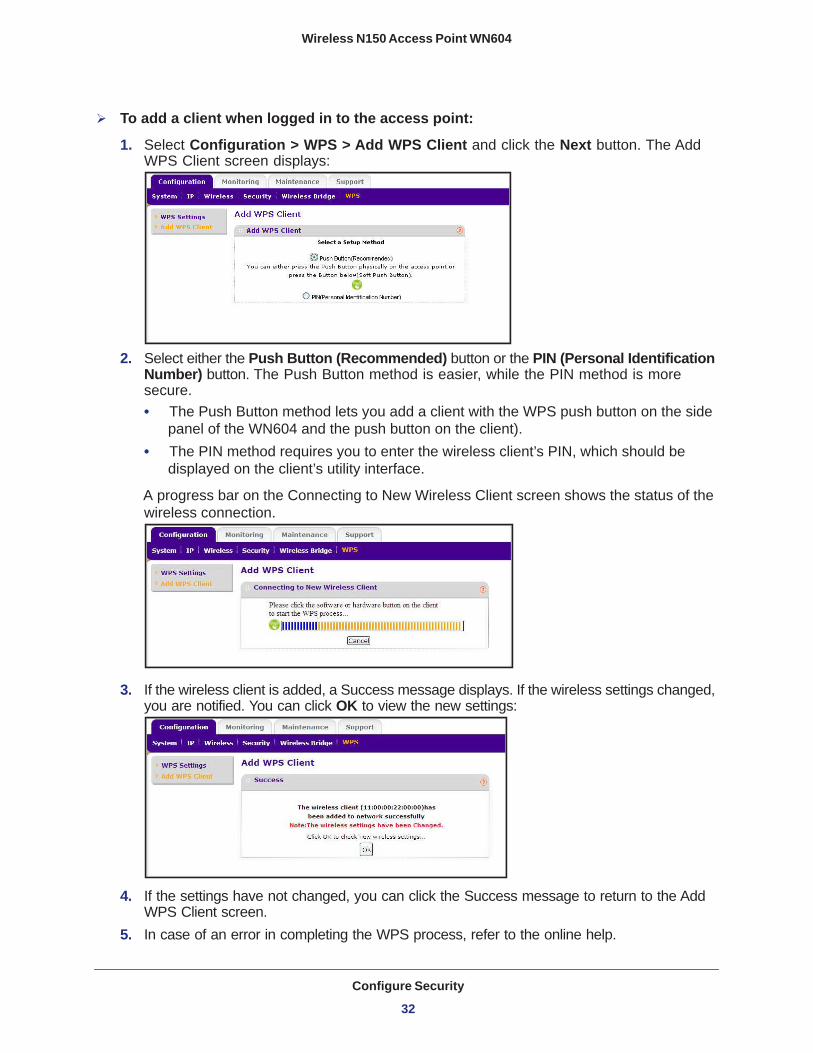
To add a client when logged in to the access point:
1. Select Configuration > WPS > Add WPS Client and click the Next button. The Add WPS Client screen displays:
2. Select either the Push Button (Recommended) button or the PIN (Personal Identification Number) button. The Push Button method is easier, while the PIN method is more secure.• The Push Button method lets you add a client with the WPS push button on the side
panel of the WN604 and the push button on the client).• The PIN method requires you to enter the wireless client’s PIN, which should be
displayed on the client’s utility interface.
A progress bar on the Connecting to New Wireless Client screen shows the status of the wireless connection.
3. If the wireless client is added, a Success message displays. If the wireless settings changed, you are notified. You can click OK to view the new settings:
4. If the settings have not changed, you can click the Success message to return to the Add WPS Client screen.
5. In case of an error in completing the WPS process, refer to the online help.
Configure Security
32

Wireless N150 Access Point WN604
Restrict Wireless Access by MAC Address
Access control lets you block the network access privilege of any specified stations through the access point. When you enable access control, the access point accepts only connections from clients on the selected access control list. This provides an additional layer of security.
Note: If you connected wirelessly to set up MAC authentication, make sure to include the MAC address of the computer you are using in the access control list. Otherwise, you will be disconnected when you click Apply. If this happens and you want to make more changes, log in to the access point with a wired connection, or wirelessly from a computer that is on the access control list.
To restrict access based on MAC addresses:
1. Select Configuration > Security > Advanced > MAC Authentication. The MAC Authentication screen displays.
2. Select the Turn Access Control On check box to enable access control feature.
In the Select the desired Access Control Database list, Local MAC Address Database is selected. The access point uses the local MAC address table for access control.
3. The Trusted Wireless Stations list shows any wireless stations you have entered. If you have not entered any wireless stations, this list is empty. To delete an existing entry, select it and then click Delete.
4. Click Refresh to refresh the available wireless stations found in your area.5. Select the stations from the list of Available Wireless Stations found in your area, or enter
the MAC address of a station to add a new station manually. (You can usually find the MAC address printed on the bottom of the wireless adapter.)
6. Click Add to add the wireless device to the Trusted Wireless Stations list. Repeat these steps for each additional device you want to add to the list.
7. Click Apply to save your wireless access control list settings.
Now, only devices on this list are allowed to wirelessly connect to the access point.
Configure Security
33

4
4. ManagementThis chapter describes how to use the management features of your access point, which you access from the Maintenance and Monitoring tabs. This chapter contains the following sections:
• Upgrade the Wireless Access Point Firmware • Configuration File Management • Change the Administrator Password • Enable the SysLog Server • Activity Log • View Summary Information • Network Traffic Statistics • Available Wireless Station Statistics
34

Wireless N150 Access Point WN604
Upgrade the Wireless Access Point Firmware
The software of the access point is stored in flash memory, and can be upgraded as new software is released by NETGEAR. You can use your browser to download upgrade files from the NETGEAR website and to send the upgrade file to the access point. The browser, such as Microsoft Internet Explorer 6.0 or later or Mozilla 1.5 or above.
To upgrade the firmware:
WARNING!
When uploading firmware to the access point, do not interrupt the web browser by closing the window, clicking a link, or loading a new page. If the browser is interrupted, the upload might fail, corrupt the software, and render the access point completely inoperable.
1. On a computer that is connected to the access point with an Ethernet cable, launch a browser.
2. Download the new software file from the NETGEAR website, and save it to your hard disk.3. Log in to the access point.4. Select Maintenance > Upgrade > Firmware Upgrade. The Firmware Upgrade screen
displays:
5. Click Browse and browse to the location of the upgrade file.6. Click Apply.
When the upload is complete, your access point automatically restarts. The upgrade process typically takes about 2 minutes.
Management
35
Wireless N150 Access Point WN604
Configuration File Management
The access point settings are stored in the access point in a configuration file. This file can be saved (backed up) to a computer, retrieved (restored), or cleared to factory default settings.
Note: If you want to restore factory settings without logging in to the access point, you can use the Reset button. See Factory Default Settings on page 59.
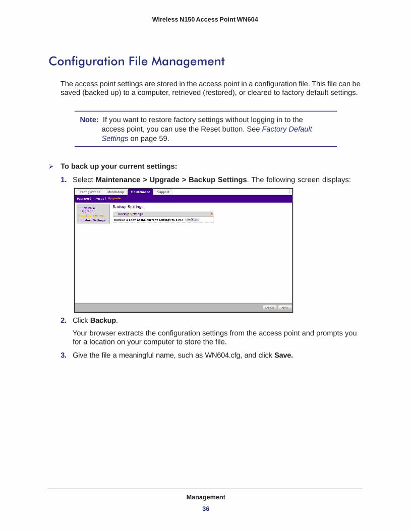
To back up your current settings:
1. Select Maintenance > Upgrade > Backup Settings. The following screen displays:
2. Click Backup.
Your browser extracts the configuration settings from the access point and prompts you for a location on your computer to store the file.
3. Give the file a meaningful name, such as WN604.cfg, and click Save.
Management
36
Wireless N150 Access Point WN604
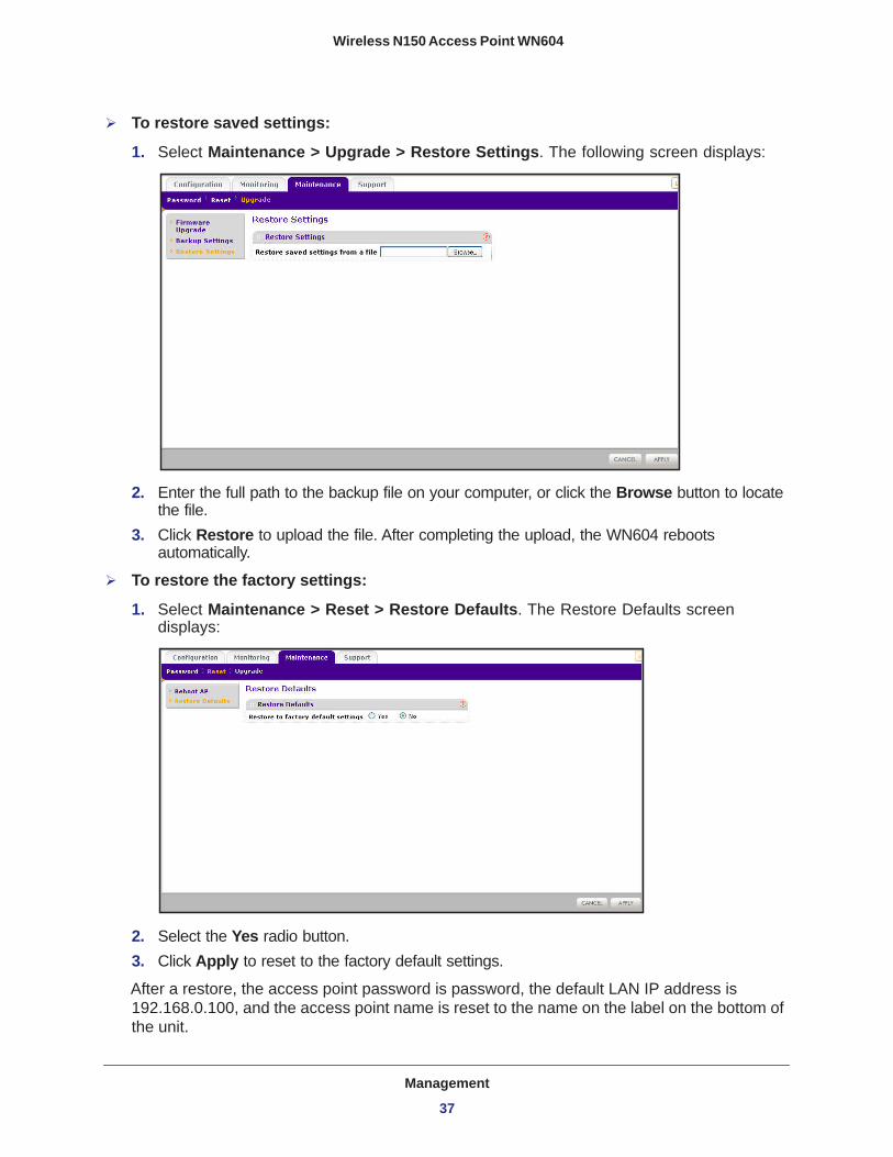
To restore saved settings:
1. Select Maintenance > Upgrade > Restore Settings. The following screen displays:
2. Enter the full path to the backup file on your computer, or click the Browse button to locate the file.
3. Click Restore to upload the file. After completing the upload, the WN604 reboots automatically.
To restore the factory settings:
1. Select Maintenance > Reset > Restore Defaults. The Restore Defaults screen displays:
2. Select the Yes radio button.3. Click Apply to reset to the factory default settings.
After a restore, the access point password is password, the default LAN IP address is 192.168.0.100, and the access point name is reset to the name on the label on the bottom of the unit.
Management
37

Wireless N150 Access Point WN604
Change the Administrator Password
The user name of admin cannot be changed. The default password is password. You should change this to a more secure password.
To change the administrator password:
1. Select Maintenance > Password. The following screen displays:
2. First enter the old password in the Current Password field. 3. Then enter the new password twice—once in the New Password field and again in the
Repeat New Password field.4. Click Apply to save your change.
Management
38

Wireless N150 Access Point WN604
Enable the SysLog Server
The syslog screen allows you to enable the syslog option if you have a syslog server on your LAN.
To enable a syslog server:
1. Select Configuration > System > Advanced > Syslog to view the following screen:
2. Select the Enable Syslog check box if you have a syslog server on your LAN. 3. Enter the IP address of your SysLog server and the port number your syslog server is
configured to use. • Syslog Server IP Address. The access point sends all the syslogs to the specified IP
address if the syslog option is enabled.• Port Number. The port number configured in the syslog server on your LAN. The
default is 514.4. Click Apply to save your settings.
Management
39
Wireless N150 Access Point WN604
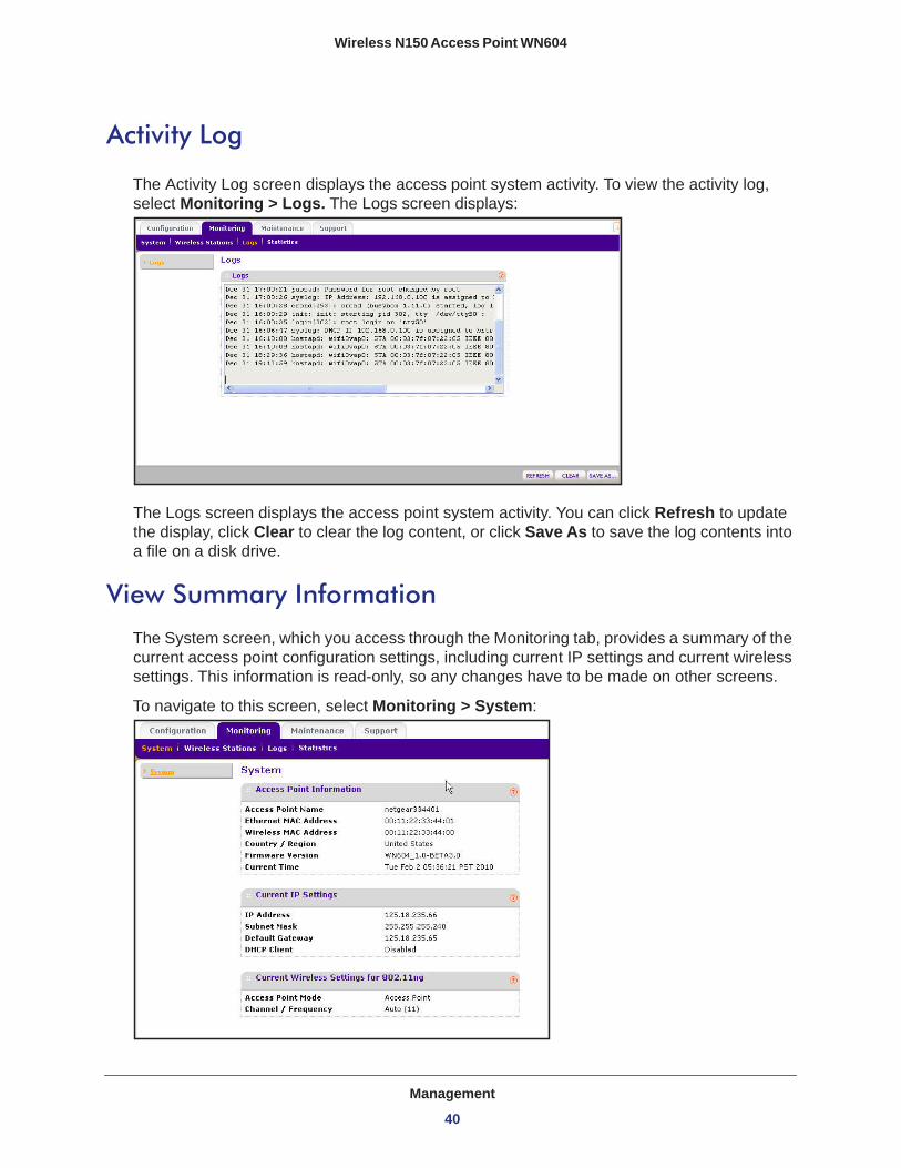
Activity Log
The Activity Log screen displays the access point system activity. To view the activity log, select Monitoring > Logs. The Logs screen displays:
The Logs screen displays the access point system activity. You can click Refresh to update the display, click Clear to clear the log content, or click Save As to save the log contents into a file on a disk drive.
View Summary Information
The System screen, which you access through the Monitoring tab, provides a summary of the current access point configuration settings, including current IP settings and current wireless settings. This information is read-only, so any changes have to be made on other screens.
To navigate to this screen, select Monitoring > System:
Management
40
Wireless N150 Access Point WN604
System Screen FieldsThis section describes the fields in this screen.
Access Point Information
Access Point Name. Indicates the NetBIOS name. You can change the default name in the General screen (Configuration > General).
Ethernet MAC Address. The Media Access Control address (MAC address) of the access point’s Ethernet port.
Wireless MAC Address. The Media Access Control address (MAC address) of the access point’s wireless card.
Country/Region. The domain or region for which the access point is licensed for use. It might not be legal to operate this access point in a region other than one of those identified in this field.
Firmware Version. The version of the firmware currently installed.
Current Time. The current time setting of the access point.
Current IP Settings
IP Address. The IP address of the access point.
Subnet Mask. The subnet mask for the IP address of the access point.
Default Gateway. The default gateway for access point communication.
DHCP Client. Enabled indicates that the current IP address of the AP was obtained from a DHCP server on your network. Disabled indicated a static IP configuration.
Current Wireless Settings for 802.11b/bg/ng
Operating Mode. Identifies the 802.11 operating mode of the WN604.
Channel/Frequency. Identifies the channel the wireless port is using. Auto is the default channel setting.
Management
41

Wireless N150 Access Point WN604
Network Traffic Statistics
The Statistics screen displays information for both wired (LAN) and wireless (WLAN) interface network traffic.
To access Statistics information:
1. Select Monitoring > Statistics. The Statistics screen displays:
2. Click Refresh to update the Statistics information for each interface.
Statistic Screen Fields
Wired Ethernet
Packets. The number of packets sent and received since the WN604 was restarted.
Bytes. The number of bytes sent and received since the WN604 was restarted.
Wireless 11b/bg/ng
Unicast Packets. The unicast packets sent and received in 802.11n/g mode since the access point was restarted.
Broadcast Packets. The broadcast packets sent and received in 802.11n/g mode since the access point was restarted.
Multicast Packets. The multicast packets sent and received in 802.11n/g mode since the access point was restarted.
Total Packets. The wireless packets sent and received in 802.11n/g mode since the access point was restarted.
Total Bytes. The wireless bytes sent and received in 802.11n/g mode since the access point was restarted.
Management
42
Wireless N150 Access Point WN604
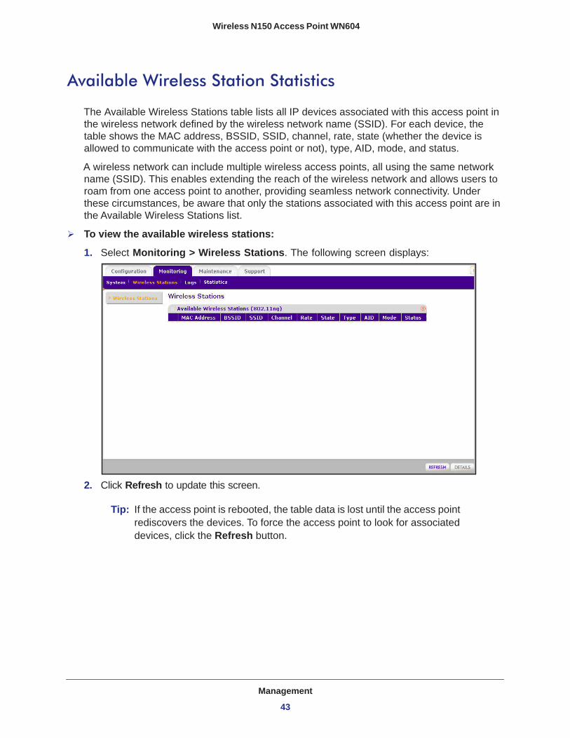
Available Wireless Station Statistics
The Available Wireless Stations table lists all IP devices associated with this access point in the wireless network defined by the wireless network name (SSID). For each device, the table shows the MAC address, BSSID, SSID, channel, rate, state (whether the device is allowed to communicate with the access point or not), type, AID, mode, and status.
A wireless network can include multiple wireless access points, all using the same network name (SSID). This enables extending the reach of the wireless network and allows users to roam from one access point to another, providing seamless network connectivity. Under these circumstances, be aware that only the stations associated with this access point are in the Available Wireless Stations list.
To view the available wireless stations:
1. Select Monitoring > Wireless Stations. The following screen displays:
2. Click Refresh to update this screen.
Tip: If the access point is rebooted, the table data is lost until the access point rediscovers the devices. To force the access point to look for associated devices, click the Refresh button.
Management
43

5
5. Advanced ConfigurationThis chapter includes the following sections:
• Schedule the Wireless Radio • Advanced Wireless Settings • Advanced QoS Settings • Enable Wireless Bridging
44

Wireless N150 Access Point WN604
Schedule the Wireless Radio
You can schedule the times when the wireless radio is on and off, for any day of the week. This feature depends on the NTP (Network Time Protocol) functionality. If an NTP client request fails, then last configured value of radio status is restored. Also, if the wireless radio is disabled, then the scheduled feature does not work.
To schedule the wireless radio:
1. Select Configuration > Wireless > Scheduled Wireless On-Off. The Scheduled Wireless On/Off screen displays.
By default, the On radio button is selected for the Scheduled Wireless On-Off field so that the wireless radio is on all the time.
2. If you want to change this so that the wireless radio is off except when you schedule it to be on, select the Off radio button.
3. For Radio Off Schedule, select the check boxes for each day on which you want to turn off the wireless radio for that entire day.
4. In the Radio On Time and Radio Off Time fields, set the period that the wireless radio is on and off for the days not selected in the radio off schedule.
5. Click Apply.
Advanced Wireless Settings
Advanced wireless settings are used to configure and enable various WLAN parameters for the 802.11b/bg/ng modes. The default WLAN parameters usually work well. However, you can use these settings to fine-tune the overall performance of your access point for your environment.
To configure advanced wireless settings:
1. Select Configuration > Wireless > Advanced > Wireless Settings.
Advanced Configuration
45

Wireless N150 Access Point WN604
The advanced Wireless Settings screen displays:,
2. Enter the appropriate information. The fields are described in the following section.3. Click Apply so that your changes take effect.
Advanced Wireless Settings Screen FieldsRTS Threshold (0-2347). Request to Send Threshold. The packet size that is used to determine if it should use the CSMA/CD (Carrier Sense Multiple Access with Collision Detection) mechanism or the CSMA/CA mechanism for packet transmission. With the CSMA/CD transmission mechanism, the transmitting station sends out the actual packet as soon as it has waited for the silence period. With the CSMA/CA transmission mechanism, the transmitting station sends out an RTS packet to the receiving station, and waits for the receiving station to send back a CTS (Clear to Send) packet before sending the actual packet data. The default is 2347.
Fragmentation Length (256-2346). This is the maximum packet size used for fragmentation. Packets larger than the size programmed in this field are fragmented. The fragmentation threshold value has to be larger than the RTS threshold value. The default is 2346.
Beacon Interval (100-1000). The beacon interval specifies the time in milliseconds between 100 and 1000 transmissions, which allows the access point to synchronize the wireless network. The default is 100.
Aggregation Length (1024-65535) (11ng). The aggregation length defines the size of aggregated packets. Larger aggregation lengths might sometimes lead to better network performance. The default is 65535.
A-MPDU (11ng). Aggregated MAC protocol data unit. Aggregates several MAC frames into a single large frame to achieve higher throughput. The default is Enable.
Advanced Configuration
46
Wireless N150 Access Point WN604
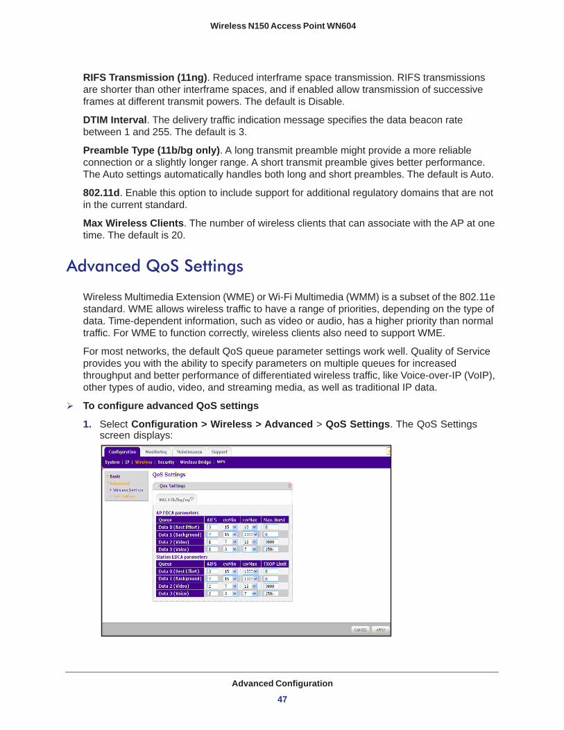
RIFS Transmission (11ng). Reduced interframe space transmission. RIFS transmissions are shorter than other interframe spaces, and if enabled allow transmission of successive frames at different transmit powers. The default is Disable.
DTIM Interval. The delivery traffic indication message specifies the data beacon rate between 1 and 255. The default is 3.
Preamble Type (11b/bg only). A long transmit preamble might provide a more reliable connection or a slightly longer range. A short transmit preamble gives better performance. The Auto settings automatically handles both long and short preambles. The default is Auto.
802.11d. Enable this option to include support for additional regulatory domains that are not in the current standard.
Max Wireless Clients. The number of wireless clients that can associate with the AP at one time. The default is 20.
Advanced QoS Settings
Wireless Multimedia Extension (WME) or Wi-Fi Multimedia (WMM) is a subset of the 802.11e standard. WME allows wireless traffic to have a range of priorities, depending on the type of data. Time-dependent information, such as video or audio, has a higher priority than normal traffic. For WME to function correctly, wireless clients also need to support WME.
For most networks, the default QoS queue parameter settings work well. Quality of Service provides you with the ability to specify parameters on multiple queues for increased throughput and better performance of differentiated wireless traffic, like Voice-over-IP (VoIP), other types of audio, video, and streaming media, as well as traditional IP data.
To configure advanced QoS settings
1. Select Configuration > Wireless > Advanced > QoS Settings. The QoS Settings screen displays:
Advanced Configuration
47

Wireless N150 Access Point WN604
2. Enter the QoS parameters. • AP EDCA Parameters. Specify the AP EDCA (Enhanced Distributed Channel
Access) parameters for different types of data transmitted from the access point to the wireless client.
• Station EDCA Parameters. Specify the Station EDCA parameters for different types of data transmitted from the wireless client to the access point. If WMM is disabled, you cannot configure Station EDCA parameters.
QoS queues and parameters are described in the following table.
3. Click Apply so that your changes take effect.
Table 3. QoS queues and parameters
QoS queue Description
Data 0 (Voice) High-priority queue, minimum delay. Time-sensitive data such as VoIP and streaming media are automatically sent to this queue.
Data 1(Video) High-priority queue, minimum delay. Time-sensitive video data is automatically sent to this queue.
Data 2 (Best Effort) Medium-priority queue, medium throughput and delay. Most traditional IP data is sent to this queue.
Data 3 (Background) Lowest-priority queue, high throughput. Bulk data that requires maximum throughput and is not time-sensitive is sent to this queue (FTP data, for example).
AIFS (Arbitration Inter-Frame Space)
Specifies a wait time (in milliseconds) for data frames. Valid values for AIFS are 1 through 255.
cwMin (Minimum Contention Window)
Upper limit (in milliseconds) of a range from which the initial random back-off wait time is determined. Valid values are 1, 3, 7, 15, 31, 63, 127, 255, 511, or 1024. The value for cwMin has to be lower than the value for cwMax.
cwMax (Maximum Contention Window)
Upper limit (in milliseconds) for the doubling of the random back-off value. Valid values are 1, 3, 7, 15, 31, 63, 127, 255, 511, or 1024. The value for cwMax has to be higher than the value for cwMin.
Max. Burst Length Specifies (in milliseconds) the maximum burst length allowed for packet bursts on the wireless network. A packet burst is a collection of multiple frames transmitted without header information. Valid values for maximum burst length are 0.0 through 999.9.
Advanced Configuration
48
Wireless N150 Access Point WN604
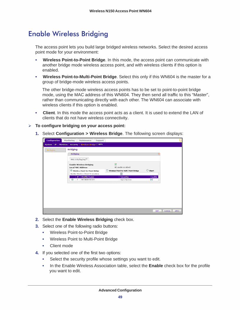
Enable Wireless Bridging
The access point lets you build large bridged wireless networks. Select the desired access point mode for your environment:
• Wireless Point-to-Point Bridge. In this mode, the access point can communicate with another bridge mode wireless access point, and with wireless clients if this option is enabled.
• Wireless Point-to-Multi-Point Bridge. Select this only if this WN604 is the master for a group of bridge-mode wireless access points.
The other bridge-mode wireless access points has to be set to point-to-point bridge mode, using the MAC address of this WN604. They then send all traffic to this “Master”, rather than communicating directly with each other. The WN604 can associate with wireless clients if this option is enabled.
• Client. In this mode the access point acts as a client. It is used to extend the LAN of clients that do not have wireless connectivity.
To configure bridging on your access point:
1. Select Configuration > Wireless Bridge. The following screen displays:
2. Select the Enable Wireless Bridging check box.3. Select one of the following radio buttons:
• Wireless Point-to-Point Bridge• Wireless Point to Multi-Point Bridge • Client mode
4. If you selected one of the first two options: • Select the security profile whose settings you want to edit.• In the Enable Wireless Association table, select the Enable check box for the profile
you want to edit.
Advanced Configuration
49

Wireless N150 Access Point WN604
• Click Edit. The Edit Security Profile screen displays:
5. Click Back to return to the previous screen and enable the profile.6. If you selected Client:
• MAC Clone. This option displays only in client mode. Use it to configure a new MAC address on the AP client if desired.
• MAC Clone Address. If the MAC Clone option has been enabled, enter the new MAC address in hexadecimal format. It is used by the client in place of its default physical address.
7. Click Apply.The following sections help you to physically configure your access point as a point-to-point bridge or a point-to-multi-point bridge.
Advanced Configuration
50

Wireless N150 Access Point WN604
Configure a Point-to-Point Bridge
Figure 5. Wireless point-to-point bridge setup
To configure a point-to-point bridge:
1. Select Configuration > Wireless Bridge > Bridging. The Bridging screen displays.2. Configure the first access point (AP 1) on LAN segment 1 in point-to-point bridge mode.3. Configure AP 2 on LAN segment 2 in point-to-point bridge mode.
AP 1 needs to have AP 2’s MAC address in its Remote MAC Address field, and AP 2 needs to have AP 1’s MAC address in its Remote MAC Address field.
4. Configure and verify the following parameters for both access points:• Verify that the LAN networks of the access points are both configured to operate in
the same LAN network address range as the LAN devices.• Both use the same ESSID, channel, authentication mode, if any, and security settings
if security is in use.5. Click Apply to save your settings.6. Verify connectivity across the LAN 1 and LAN 2.
A computer on either LAN segment should be able to connect to the Internet or share files and printers of any other PCs or servers connected to LAN segment 1 or LAN segment 2.
AP 1
LAN segment 1 LAN segment 2
point-to-pointbridge mode
AP 2point-to-pointbridge mode
Hub or switchRouter
Advanced Configuration
51
Wireless N150 Access Point WN604
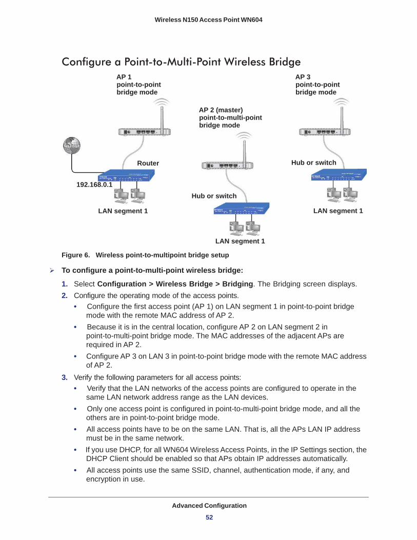
Configure a Point-to-Multi-Point Wireless Bridge
Figure 6. Wireless point-to-multipoint bridge setup
To configure a point-to-multi-point wireless bridge:
1. Select Configuration > Wireless Bridge > Bridging. The Bridging screen displays.2. Configure the operating mode of the access points.
• Configure the first access point (AP 1) on LAN segment 1 in point-to-point bridge mode with the remote MAC address of AP 2.
• Because it is in the central location, configure AP 2 on LAN segment 2 in point-to-multi-point bridge mode. The MAC addresses of the adjacent APs are required in AP 2.
• Configure AP 3 on LAN 3 in point-to-point bridge mode with the remote MAC address of AP 2.
3. Verify the following parameters for all access points:• Verify that the LAN networks of the access points are configured to operate in the
same LAN network address range as the LAN devices.• Only one access point is configured in point-to-multi-point bridge mode, and all the
others are in point-to-point bridge mode.• All access points have to be on the same LAN. That is, all the APs LAN IP address
must be in the same network.• If you use DHCP, for all WN604 Wireless Access Points, in the IP Settings section, the
DHCP Client should be enabled so that APs obtain IP addresses automatically.• All access points use the same SSID, channel, authentication mode, if any, and
encryption in use.
AP 1point-to-pointbridge mode
AP 2 (master)point-to-multi-pointbridge mode
AP 3point-to-pointbridge mode
LAN segment 1
LAN segment 1
LAN segment 1
Router
Hub or switch
Hub or switch
192.168.0.1
Advanced Configuration
52
Wireless N150 Access Point WN604
• All point-to-point access points need to have the AP 2 MAC address in their Remote AP MAC address fields.
4. Verify connectivity across the LANs. • A computer on any LAN segment should be able to connect to the Internet or share
files and printers with any other PCs or servers connected to any of the three LAN segments.
• Wireless stations can connect to the access points in the preceding illustration. If you require wireless stations to access any LAN segment, you can add additional access points configured in wireless access point mode to any LAN segment.
5. Click Apply to save your settings.
Note: You can extend this multi-point bridging by adding additional access points configured in point-to-point mode for each additional LAN segment. Furthermore, you can extend the range of the wireless network with NETGEAR wireless antenna accessories.
Advanced Configuration
53
6
6. TroubleshootingThis chapter includes the following sections:
• Troubleshooting with the LEDs • Cannot Access the Internet or the LAN Wirelessly • Cannot Connect to the Access Point to Configure It • Time-Out Error
54

Wireless N150 Access Point WN604
Troubleshooting with the LEDs
You can use the LEDs on the front panel of the access point for troubleshooting.
All LEDs Are OffIt takes a few seconds for the Power LED to light up. Wait a minute and check the Power LED again.
If the access point has no power.
• Make sure the power adapter is connected to the access point.• Make sure the power adapter is connected to a functioning power outlet. If it is in a power
strip, make sure the power strip is turned on. If it is plugged directly into the wall, verify that it is not a switched outlet.
• Make sure you are using the correct NETGEAR power adapter supplied with your access point.
WiFi LED Is OffThe wireless radio is turned off or the antenna is not working. There are two ways to turn off the wireless radio--the Wireless On/Off button on the side of the access point, and the Schedule Wireless Radio feature.
Figure 7. You can use the Wireless On/Off button to control the wireless radio
For information about the Schedule Wireless Radio feature, see Schedule the Wireless Radio on page 45.
Check the following:
1. Make sure that the wireless radio is turned on. If it is, and the WiFi LED stays off, disconnect the access point from its power source and then plug it in again.
2. Make sure the antenna is securely connected to the access point. 3. Contact NETGEAR technical support if the WiFi LED remains off.
Wireless On/Off
Troubleshooting
55

Wireless N150 Access Point WN604
LAN LED Is OffThere is a hardware connection problem. Check these items:
• Make sure the cable connectors are securely plugged in at the access point and the network device (hub, switch, or router). A switch, hub, or router has to be installed between the access point and the Ethernet LAN or broadband modem.
• LAN LED does not light up if there is a 10 Mbps link. In such cases, the LAN LED blinks if there is activity.
• Make sure the connected device is turned on.• Be sure the correct cable is used. Use a standard Category 5 Ethernet patch cable. If the
network device has Auto Uplink™ (MDI/MDIX) ports, you can use either a crossover cable or a normal patch cable.
Cannot Access the Internet or the LAN Wirelessly
There is a configuration problem. Check these items:
• You might not have restarted the computer with the wireless adapter to have TCP/IP changes take effect. Restart the computer.
• The computer with the wireless adapter might not have the correct TCP/IP settings to communicate with the network. Restart the computer and check that TCP/IP is set up correctly for that network. The usual setting for Windows network properties is to obtain an IP address automatically.”
• The access point’s default values might not work with your network. Check the access point’s default configuration against the configuration of other devices in your network.
Cannot Connect to the Access Point to Configure It
Check these items:
• The access point is correctly installed, LAN connections are OK, and it is powered on. Check that the LAN port LED is green to verify that the Ethernet connection is OK.
• The default configuration of the WN604 is for a static IP address of 192.168.0.100 and a subnet mask of 255.255.255.0 with DHCP disabled. Make sure your network configuration settings are correct.
• If you are using the NetBIOS name of the access point to connect, ensure that your computer and the access point are on the same network segment or that there is a WINS server on your network.
• If your computer is set to obtain an IP address automatically (DHCP client), restart it.• If your computer uses a fixed (static) IP address, ensure that it is using an IP address in
the range of the WN604. The access point default IP address is 192.168.0.100, and the default subnet mask is 255.255.255.0.
Troubleshooting
56
Wireless N150 Access Point WN604
Time-Out Error
If you get a time-out error when you enter a URL or IP address, try these suggestions.
• Check to see if other PCs work. If they do, ensure that your PC’s TCP/IP settings are correct. If using a fixed (static) IP address, check the subnet mask, default gateway, DNS, and IP addresses.
• If the PCs are configured correctly, but still not working, ensure that the access point is connected and turned on. Connect to it and check its settings. If you cannot connect to it, check the LAN and power connections.
• If the access point is configured correctly, check your Internet connection to make sure that it is working correctly.
• Try again.
Troubleshooting
57
A
A. Supplemental InformationThis appendix includes the following sections:
• Factory Default Settings • Technical Specifications
58

Wireless N150 Access Point WN604
Factory Default Settings
The Reset button has two functions:
• Reboot. When pressed and released quickly, the access point restarts.• Reset to Factory Defaults. This button can also be used to clear all data and restore all
settings to the factory default values.
To clear all data and restore the factory default values:
1. Power off the access point and power it back on.2. Use something with a small point, such as a pen, to press the Reset button in and hold it in
for at least 5 seconds until the WiFi LED blinks rapidly.
3. Release the Reset button.
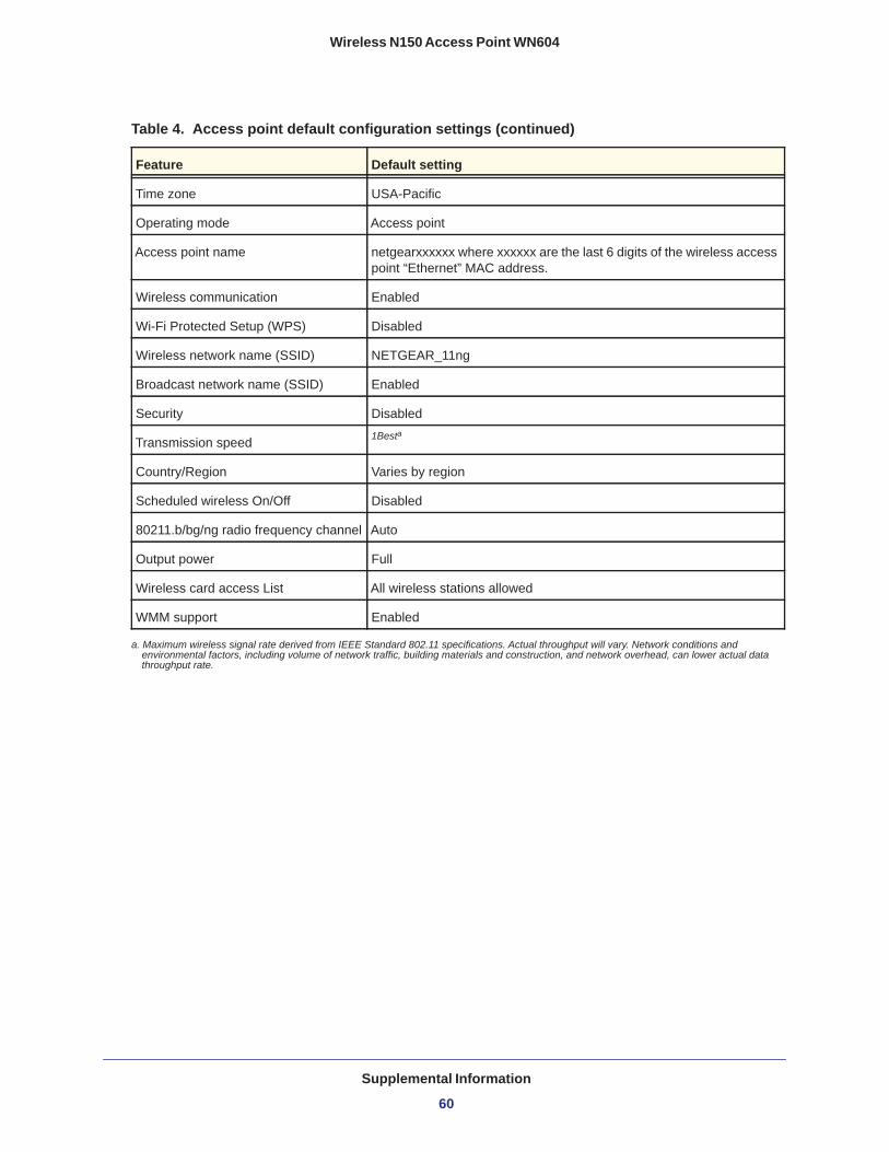
Your device returns to the factory configuration settings shown in the following table.
Table 4. Access point default configuration settings
Feature Default setting
Login URL www.routerlogin.net or www.routerlogin.com
User name (case-sensitive) printed on product label
admin
Password (case-sensitive) printed on product label
password
Static IP address 192.168.0.100
Ethernet MAC address See bottom label.
Port speed 10/100
Subnet mask 255.255.255.0
DHCP client Disabled
Supplemental Information
59
Wireless N150 Access Point WN604
Time zone USA-Pacific
Operating mode Access point
Access point name netgearxxxxxx where xxxxxx are the last 6 digits of the wireless access point “Ethernet” MAC address.
Wireless communication Enabled
Wi-Fi Protected Setup (WPS) Disabled
Wireless network name (SSID) NETGEAR_11ng
Broadcast network name (SSID) Enabled
Security Disabled
Transmission speed 1Besta
Country/Region Varies by region
Scheduled wireless On/Off Disabled
80211.b/bg/ng radio frequency channel Auto
Output power Full
Wireless card access List All wireless stations allowed
WMM support Enabled
a. Maximum wireless signal rate derived from IEEE Standard 802.11 specifications. Actual throughput will vary. Network conditions and environmental factors, including volume of network traffic, building materials and construction, and network overhead, can lower actual data throughput rate.
Table 4. Access point default configuration settings (continued)
Feature Default setting
Supplemental Information
60

Wireless N150 Access Point WN604
Technical SpecificationsTable 5. WN604 Technical Specifications
Feature Specification
802.11g data rates 1, 2, 5.5, 11, 12, 18, 24, 36, 38, 54, & 108 Mbps (Auto-rate capable)
802.11ng data rates Data rates for channel width = 20 MHz and guard Interval = short (400ms): Best, 7.2 Mbps, 14.4 Mbps, 21.7 Mbps, 28.9 Mbps, 43.3 Mbps, 57.8 Mbps, 65 Mbps, 72.2 Mbps
Data Rates for Channel Width = 20 MHz and guard Interval = long (800 ms): Best, 6.5 Mbps, 13 Mbps, 19.5 Mbps, 26 Mbps, 39 Mbps, 52 Mbps, 58.5 Mbps, 65 Mbps
Data Rates for channel width = 40 MHz and guard Interval = short: Best, 15 Mbps, 30 Mbps, 45 Mbps, 60 Mbps, 90 Mbps, 120 Mbps, 135 Mbps, 150 Mbps
Data Rates for channel width = 40 MHz and guard Interval = long: Best, 13.5 Mbps, 27 Mbps, 40.5 Mbps, 54 Mbps, 81 Mbps, 108 Mbps, 121.5 Mbps, 135 Mbps
Operating frequencies 2.412–2.462 GHz (US) 2.457–2.462 GHz (Spain)2.412–2.484 GHz (Japan)2.457–2.472 GHz (France)2.412–2.472 GHz (Europe ETSI)
802.11 b/bg/ng encryption
64-bits, 128-bit and 152-bit WEP, AES, TKIP data encryption
Network management Web-based configuration and status monitoring
Maximum clients Limited by the amount of wireless network traffic generated by each node; maximum 20 supported.
Status LEDs Power, WPS, WiFi, Ethernet LAN (4)
Power adapter 12V DC, 1 A
Electromagnetic compliance
FCC Part 15 Class B and Class E, CE, and C-TICK
Environmental specifications
Operating temperature: 0 to 40° C; Storage temperature: –20 to 70° COperating humidity: 10–90% RH; Storage humidity: 5–95% RH
Supplemental Information
61

Wireless N150 Access Point WN604
Supplemental Information
62