Embed Size (px)
Citation preview
Network Camera Installation Manual
V5.0
Hangzhou Hikvision Digital Technology Co., Ltd.
http://www.hikvision.com
UD.6L0201A1008A01
Installation Manual of Network Camera
1
Thank you for purchasing our product. If there are any questions, or requests, please do not hesitate
to contact the dealer.
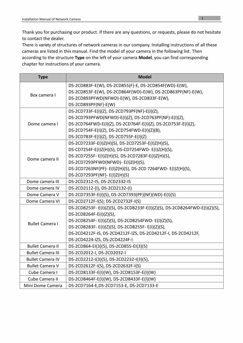
There is variety of structures of network cameras in our company. Installing instructions of all these
cameras are listed in this manual. Find the model of your camera in the following list. Then
according to the structure Type on the left of your camera Model, you can find corresponding
chapter for instructions of your camera.
Type Model
Box camera I
DS-2CD883F-E(W), DS-2CD855(F)-E, DS-2CD854F(WD)-E(W),
DS-2CD853F-E(W), DS-2CD864F(WD)-E(W), DS-2CD863PF(NF)-E(W),
DS-2CD893PFWD(NFWD)-E(W), DS-2CD833F-E(W),
DS-2CD893PF(NF)-E(W)
Dome camera I
DS-2CD733F-E(I)(Z), DS-2CD793PF(NF)-E(I)(Z),
DS-2CD793PFWD(NFWD)-E(I)(Z), DS-2CD763PF(NF)-E(I)(Z),
DS-2CD764FWD-E(I)(Z), DS-2CD764F-E(I)(Z), DS-2CD753F-E(I)(Z),
DS-2CD754F-E(I)(Z), DS-2CD754FWD-E(I)(Z)(B),
DS-2CD783F-E(I)(Z), DS-2CD755F-E(I)(Z)
Dome camera II
DS-2CD7233F-E(I)Z(H)(S), DS-2CD7253F-E(I)Z(H)(S),
DS-CD7254F-E(I)Z(H)(S), DS-CD7254FWD- E(I)Z(H)(S),
DS-2CD7255F- E(I)Z(H)(S), DS-2CD7283F-E(I)Z(H)(S),
DS-2CD7293PFWD(NFWD)- E(I)Z(H)(S),
DS-2CD7263NF(PF)- E(I)Z(H)(S), DS-2CD 7264FWD- E(I)Z(H)(S),
DS-2CD7293PF(NF)- E(I)Z(H)(S)
Dome camera III DS-2CD2312-I5, DS-2CD2332-I5
Dome camera IV DS-2CD2112-(I), DS-2CD2132-(I)
Dome Camera V DS-2CD7353F-E(I)(S), DS-2CD7393(PF)(NF)(WD)-E(I)(S)
Dome Camera VI DS-2CD2712F-I(S); DS-2CD2732F-I(S)
Bullet Camera I
DS-2CD8253F- E(I)(Z)(S), DS-2CD8233F-E(I)(Z)(S), DS-2CD8264FWD-E(I)(Z)(S),
DS-2CD8264F-E(I)(Z)(S),
DS-2CD8254F- E(I)(Z)(S), DS-2CD8254FWD- E(I)(Z)(S),
DS-2CD8283F- E(I)(Z)(S), DS-2CD8255F- E(I)(Z)(S),
DS-2CD4212F-IS, DS-2CD4212F-IZS, DS-2CD4212F-I, DS-2CD4212F,
DS-2CD4224-IZS, DS-2CD4224F-I
Bullet Camera II DS-2CD864-EI(3)(5), DS-2CD855-EI(3)(5)
Bullet Camera III DS-2CD2012-I, DS-2CD2032-I
Bullet Camera IV DS-2CD2212-I(3)(5), DS-2CD2232-I(3)(5),
Bullet Camera V DS-2CD2612F-I(S), DS-2CD2632F-I(S)
Cube Camera I DS-2CD8133F-E(I)(W), DS-2CD8153F-E(I)(W)
Cube Camera II DS-2CD8464F-E(I)(W), DS-2CD8433F-E(I)(W)
Mini Dome Camera DS-2CD7164-E,DS-2CD7153-E, DS-2CD7133-E
Installation Manual of Network Camera
2
This manual may contain several technical incorrect places or printing errors, and the content is
subject to change without notice. The updates will be added to the new version of this manual. We
will readily improve or update the products or procedures described in the manual.
DISCLAIMER STATEMENT
“Underwriters Laboratories Inc. (“UL”) has not tested the performance or reliability of the security
or signaling aspects of this product. UL has only tested for fire, shock or casualty hazards as outlined
in UL’s Standard(s) for Safety, UL60950-1. UL Certification does not cover the performance or
reliability of the security or signaling aspects of this product. UL MAKES NO REPRESENTATIONS,
WARRANTIES OR CERTIFICATIONS WHATSOEVER REGARDING THE PERFORMANCE OR RELIABILITY
OF ANY SECURITY OR SIGNALING RELATED FUNCTIONS OF THIS PRODUCT.”
Installation Manual of Network Camera
3
Safety Instruction
These instructions are intended to ensure that the user can use the product correctly to avoid
danger or property loss.
The precaution measure is divided into ‘Warnings’ and ‘Cautions’:
Warnings: Serious injury or death may be caused if any of these warnings are neglected.
Cautions: Injury or equipment damage may be caused if any of these cautions are neglected.
Warnings Follow these safeguards to
prevent serious injury or death.
Cautions Follow these precautions to
prevent potential injury or material
damage.
Warnings:
Please adopt the power adapter which can meet the safety extra low voltage (SELV) standard.
And source with DC 12V or AC 24V (depending on models) according to the IEC60950-1 and
Limited Power Source standard.
If the product does not work properly, please contact your dealer or the nearest service center.
Never attempt to disassemble the camera yourself. (We shall not assume any responsibility for
problems caused by unauthorized repair or maintenance.)
To reduce the risk of fire or electrical shock, do not expose this product to rain or moisture.
This installation should be made by a qualified service person and should conform to all the local
codes.
Please install blackouts equipment into the power supply circuit for convenient supply
interruption.
Please make sure that the ceiling can support more than 50(N) Newton gravities if the camera is
fixed to the ceiling.
If the product does not work properly, please contact your dealer or the nearest service center.
Never attempt to disassemble the camera yourself. (We shall not assume any responsibility for
problems caused by unauthorized repair or maintenance.)
Installation Manual of Network Camera
4
Notice:
Make sure the power supply voltage is correct before using the camera.
Do not drop the camera or subject it to physical shock.
Do not touch sensor modules with fingers. If cleaning is necessary, use a clean cloth with a bit
of ethanol and wipe it gently. If the camera will not be used for an extended period of time, put
on the lens cap to protect the sensor from dirt.
Do not aim the camera lens at the strong light such as sun or incandescent lamp. The strong
light can cause fatal damage to the camera.
The sensor may be burned out by a laser beam, so when any laser equipment is being used,
make sure that the surface of the sensor not be exposed to the laser beam.
Do not place the camera in extremely hot, cold temperatures (the operating temperature
should be between -10°C ~ 60°C), dusty or damp environment, and do not expose it to high
electromagnetic radiation.
To avoid heat accumulation, good ventilation is required for a proper operating environment.
Keep out of water and any liquid.
While shipping, the camera should be packed in its original packing.
Improper use or replacement of the battery may result in hazard of explosion. Please use the
manufacturer recommended battery type.
Installation Manual of Network Camera
5
Table of Contents
CHAPTER 1 INTRODUCTION .................................................................................................................................... 1
1.1 APPLICATIONS .......................................................................................................................................................... 1
1.2 PREPARATIONS .......................................................................................................................................................... 1
CHAPTER 2 BOX CAMERA INSTALLATION ................................................................................................................. 2
2.1 APPEARANCE DESCRIPTION ......................................................................................................................................... 2
2.1.1 Box Camera I .................................................................................................................................................... 2
2.2 INSTALLATION ........................................................................................................................................................... 4
2.2.2 Lens Installation ............................................................................................................................................... 4
2.2.3 Wiring .............................................................................................................................................................. 4
2.2.4 Mounting ......................................................................................................................................................... 5
CHAPTER 3 DOME CAMERA INSTALLATION ............................................................................................................. 8
3.1 DOME CAMERA I ...................................................................................................................................................... 8
3.1.1 Appearance Description ................................................................................................................................... 8
3.1.2 Installation ....................................................................................................................................................... 9
3.2 DOME CAMERA II ................................................................................................................................................... 14
3.2.3 Appearance Description ................................................................................................................................. 14
3.2.4 Installation ..................................................................................................................................................... 15
3.3 DOME CAMERA III .................................................................................................................................................. 29
3.3.1 Overview ........................................................................................................................................................ 29
3.3.2 Installation ..................................................................................................................................................... 31
3.4 DOME CAMERA IV .................................................................................................................................................. 34
3.4.3 Overview ........................................................................................................................................................ 35
3.4.4 Installation ..................................................................................................................................................... 35
3.5 DOME CAMERA V ................................................................................................................................................... 38
3.5.5 Overview ........................................................................................................................................................ 38
3.5.6 Installation ..................................................................................................................................................... 39
3.6 DOME CAMERA VI .................................................................................................................................................. 42
3.6.7 Overview ........................................................................................................................................................ 42
3.6.8 Installation ..................................................................................................................................................... 43
IMAGE AND FOCUS ADJUSTING ............................................................................................................................................... 54
CHAPTER 4 BULLET CAMERA INSTALLATION ........................................................................................................... 57
4.1 BULLET CAMERA I ................................................................................................................................................... 57
4.1.1 Appearance Description ................................................................................................................................. 57
4.1.2 Installation ..................................................................................................................................................... 58
4.2 BULLET CAMERA II .................................................................................................................................................. 60
4.2.1 Appearance Description ................................................................................................................................. 60
4.2.2 Installation ..................................................................................................................................................... 61
4.3 BULLET CAMERA III ................................................................................................................................................. 63
4.3.3 Appearance Description ................................................................................................................................. 63
Installation Manual of Network Camera
6
4.3.4 Installation ..................................................................................................................................................... 63
4.4 BULLET CAMERA IV ................................................................................................................................................. 65
4.4.5 Appearance .................................................................................................................................................... 65
4.4.6 Installation ..................................................................................................................................................... 65
4.5 BULLET CAMERA V .................................................................................................................................................. 67
4.5.1 Appearance .................................................................................................................................................... 67
4.5.2 Installation ..................................................................................................................................................... 68
CHAPTER 5 CUBE CAMERA INSTALLATION .............................................................................................................. 75
5.1 CUBE CAMERA I ...................................................................................................................................................... 76
5.1.1 Appearance Description ................................................................................................................................. 76
5.1.2 Installation ..................................................................................................................................................... 77
5.2 CUBE CAMERA II ..................................................................................................................................................... 79
5.2.3 Appearance Description ................................................................................................................................. 79
5.2.4 Installation ..................................................................................................................................................... 80
CHAPTER 6 MINI DOME CAMERA INSTALLATION ................................................................................................... 84
6.1 APPEARANCE DESCRIPTION ....................................................................................................................................... 84
6.2 INSTALLATION ......................................................................................................................................................... 85
Installation Manual of Network Camera
1
Chapter 1 Introduction The network camera is a kind of embedded digital surveillance product that combines the features
of both traditional analog camera and net DVS (Digital Video Server). With a built-in video server,
the network camera is capable of providing real-time video stream compression, processing, video
analysis and transmission simultaneously. Applying the latest processing chip and hardware
platform, the network camera can be widely applied to various surveillance and image processing
systems with high reliability and stability.
1.1 Applications
This camera can be adopted for network video surveillance systems, e.g.:
Network surveillance for over-the-counter activities in the banks, ATMs, supermarkets and
factories.
Remote surveillance systems for nursing homes, kindergartens and schools.
Artificial Intelligent access control systems .
Artificial Intelligent office building/residential compounds management systems.
Unguarded power station and telecommunication base station surveillance systems.
Pipelining and warehousing monitoring systems.
Surveillance systems for airports, railway stations, bus stops, etc.
1.2 Preparations
Before you start:
Verify the package contents are correct by checking the items against the packing list.
Read the following contents carefully before installation.
Make sure that all the related equipment is power-off during installation.
Check whether the power supply is matched with your AC outlet to avoid damage.
Do not place the camera in extremely hot or damp environment. To avoid heat
accumulation, good ventilation of the operating environment is required.
If the product does not function properly, please contact your dealer or the nearest service
center. Do not disassemble the camera for repair or maintenance by yourself.
Installation Manual of Network Camera
2
Chapter 2 Box Camera Installation
2.1 Appearance Description
2.1.1 Box Camera I
Camera description:
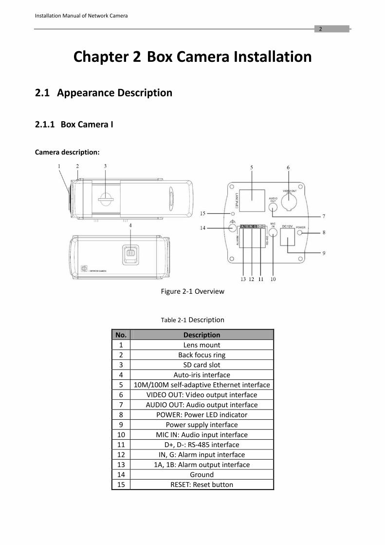
Figure 2-1 Overview
Table 2-1 Description
No. Description
1 Lens mount
2 Back focus ring
3 SD card slot
4 Auto-iris interface
5 10M/100M self-adaptive Ethernet interface
6 VIDEO OUT: Video output interface
7 AUDIO OUT: Audio output interface
8 POWER: Power LED indicator
9 Power supply interface
10 MIC IN: Audio input interface
11 D+, D-: RS-485 interface
12 IN, G: Alarm input interface
13 1A, 1B: Alarm output interface
14 Ground
15 RESET: Reset button
Installation Manual of Network Camera
3
Notes: To reset the default parameters to the camera, you need to press and hold the RESET
button and power on the camera. After the power on of the camera, you must still press and hold the Reset button for about 20 seconds.
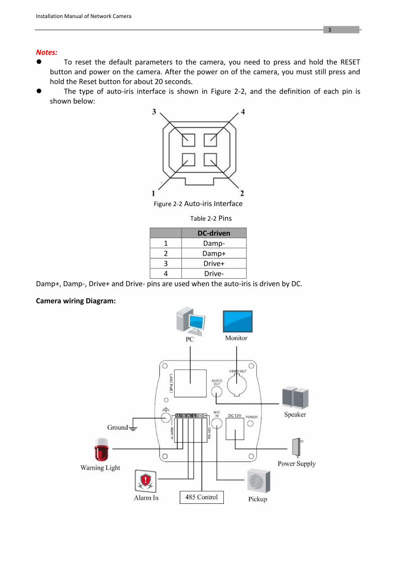
The type of auto-iris interface is shown in Figure 2-2, and the definition of each pin is shown below:
Figure 2-2 Auto-iris Interface
Table 2-2 Pins
DC-driven
1 Damp-
2 Damp+
3 Drive+
4 Drive-
Damp+, Damp-, Drive+ and Drive- pins are used when the auto-iris is driven by DC.
Camera wiring Diagram:
Installation Manual of Network Camera
4
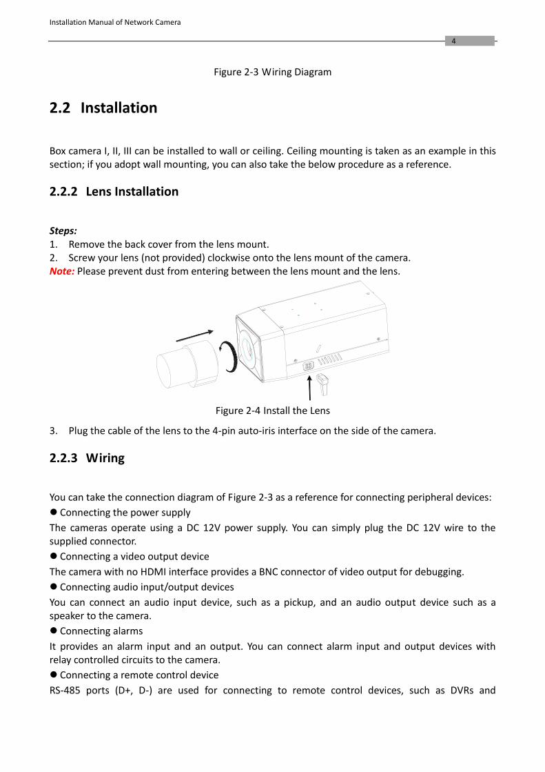
Figure 2-3 Wiring Diagram
2.2 Installation
Box camera I, II, III can be installed to wall or ceiling. Ceiling mounting is taken as an example in this section; if you adopt wall mounting, you can also take the below procedure as a reference.
2.2.2 Lens Installation
Steps: 1. Remove the back cover from the lens mount. 2. Screw your lens (not provided) clockwise onto the lens mount of the camera. Note: Please prevent dust from entering between the lens mount and the lens.
Figure 2-4 Install the Lens
3. Plug the cable of the lens to the 4-pin auto-iris interface on the side of the camera.
2.2.3 Wiring
You can take the connection diagram of Figure 2-3 as a reference for connecting peripheral devices:
Connecting the power supply
The cameras operate using a DC 12V power supply. You can simply plug the DC 12V wire to the supplied connector.
Connecting a video output device
The camera with no HDMI interface provides a BNC connector of video output for debugging.
Connecting audio input/output devices
You can connect an audio input device, such as a pickup, and an audio output device such as a speaker to the camera.
Connecting alarms
It provides an alarm input and an output. You can connect alarm input and output devices with relay controlled circuits to the camera.
Connecting a remote control device
RS-485 ports (D+, D-) are used for connecting to remote control devices, such as DVRs and
Installation Manual of Network Camera
5
keyboards.
Grounding
The ground screw can be connected for grounding.
2.2.4 Mounting
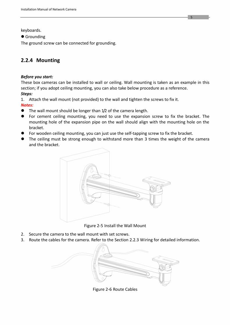
Before you start: These box cameras can be installed to wall or ceiling. Wall mounting is taken as an example in this section; if you adopt ceiling mounting, you can also take below procedure as a reference. Steps: 1. Attach the wall mount (not provided) to the wall and tighten the screws to fix it. Notes: The wall mount should be longer than 1/2 of the camera length. For cement ceiling mounting, you need to use the expansion screw to fix the bracket. The
mounting hole of the expansion pipe on the wall should align with the mounting hole on the bracket.
For wooden ceiling mounting, you can just use the self-tapping screw to fix the bracket. The ceiling must be strong enough to withstand more than 3 times the weight of the camera
and the bracket.
Figure 2-5 Install the Wall Mount
2. Secure the camera to the wall mount with set screws. 3. Route the cables for the camera. Refer to the Section 2.2.3 Wiring for detailed information.
Figure 2-6 Route Cables
Installation Manual of Network Camera
6
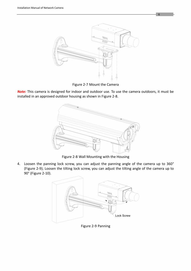
Figure 2-7 Mount the Camera
Note: This camera is designed for indoor and outdoor use. To use the camera outdoors, it must be installed in an approved outdoor housing as shown in Figure 2-8.
Figure 2-8 Wall Mounting with the Housing
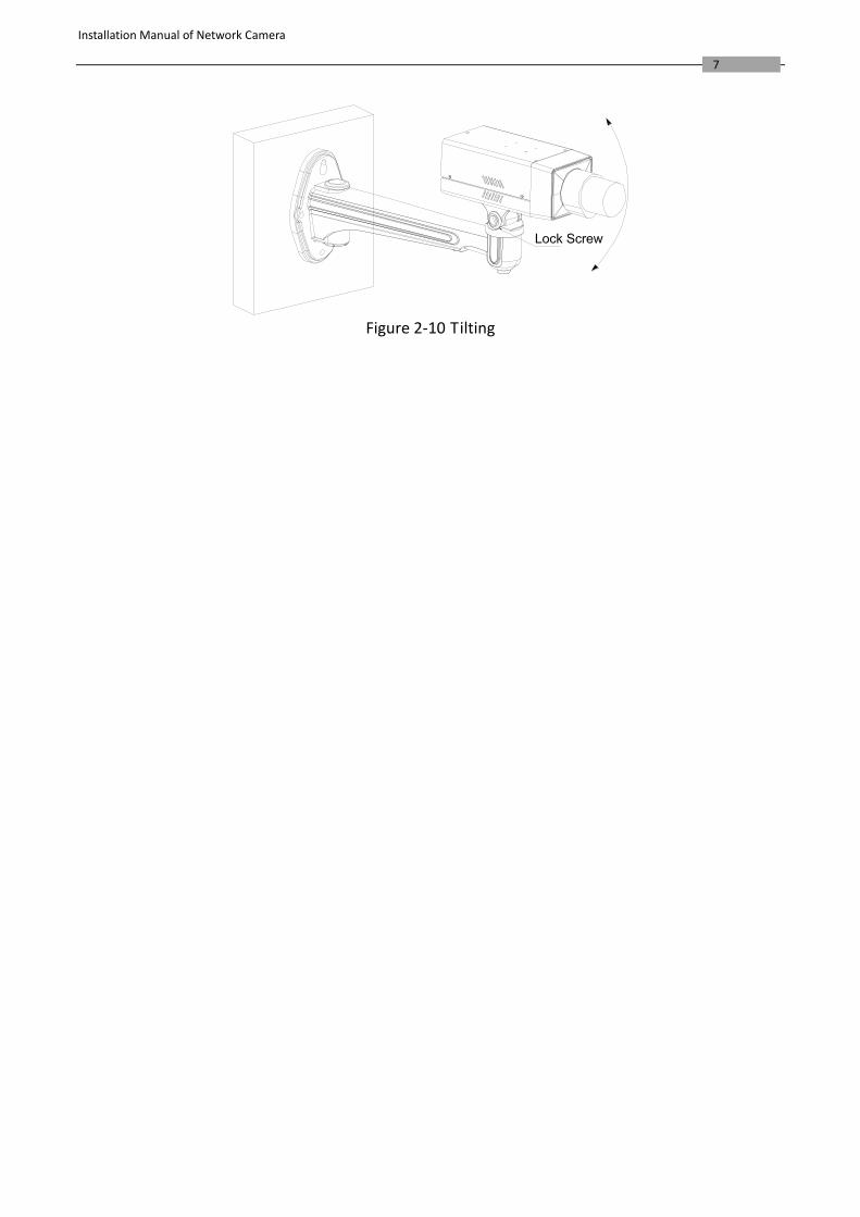
4. Loosen the panning lock screw, you can adjust the panning angle of the camera up to 360° (Figure 2-9); Loosen the tilting lock screw, you can adjust the tilting angle of the camera up to 90° (Figure 2-10).
Figure 2-9 Panning
Installation Manual of Network Camera
7
Figure 2-10 Tilting
Installation Manual of Network Camera
8
Chapter 3 Dome Camera Installation
3.1 Dome Camera I
3.1.1 Appearance Description
Camera description:
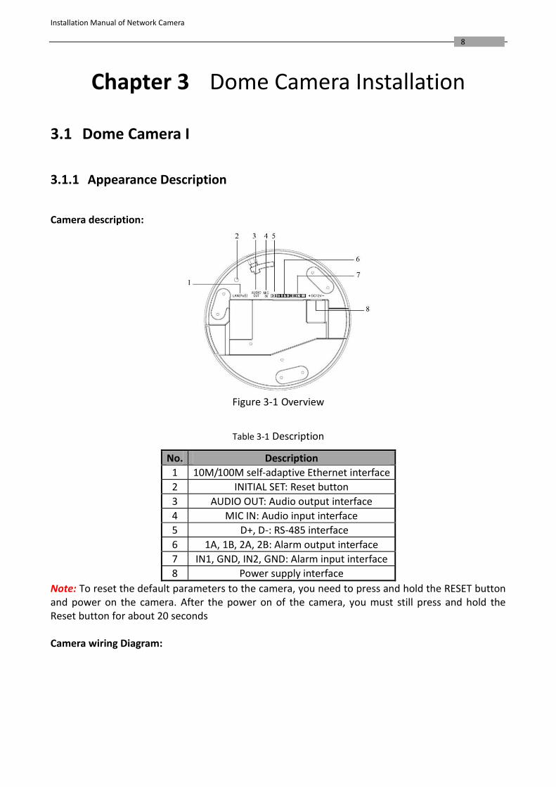
Figure 3-1 Overview
Table 3-1 Description
No. Description
1 10M/100M self-adaptive Ethernet interface
2 INITIAL SET: Reset button
3 AUDIO OUT: Audio output interface
4 MIC IN: Audio input interface
5 D+, D-: RS-485 interface
6 1A, 1B, 2A, 2B: Alarm output interface
7 IN1, GND, IN2, GND: Alarm input interface
8 Power supply interface
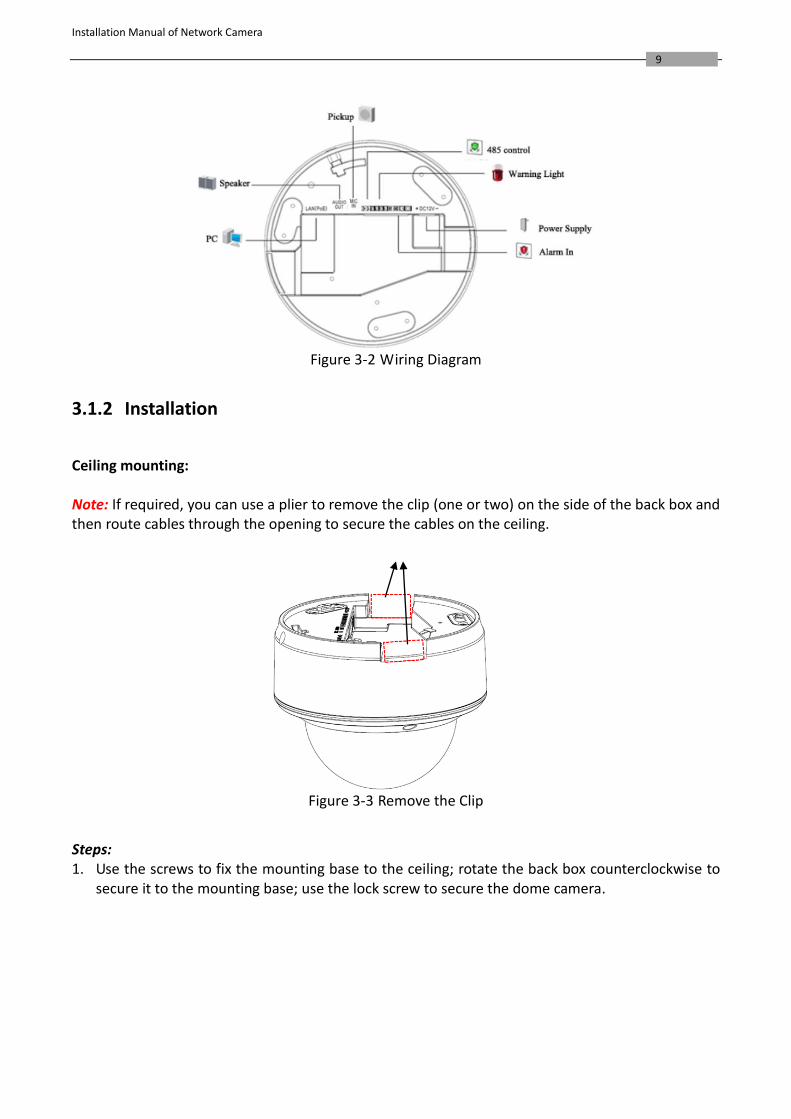
Note: To reset the default parameters to the camera, you need to press and hold the RESET button and power on the camera. After the power on of the camera, you must still press and hold the Reset button for about 20 seconds Camera wiring Diagram:
Installation Manual of Network Camera
9
Figure 3-2 Wiring Diagram
3.1.2 Installation
Ceiling mounting: Note: If required, you can use a plier to remove the clip (one or two) on the side of the back box and then route cables through the opening to secure the cables on the ceiling.
Figure 3-3 Remove the Clip
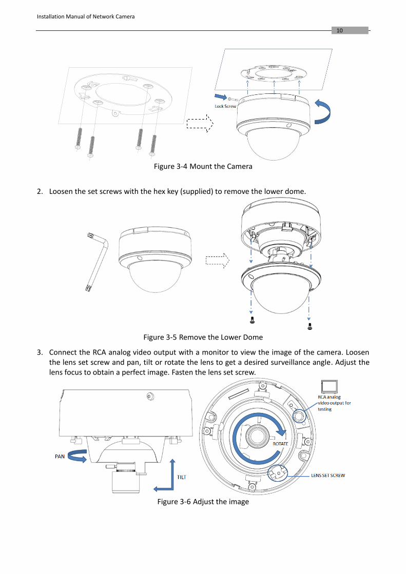
Steps: 1. Use the screws to fix the mounting base to the ceiling; rotate the back box counterclockwise to
secure it to the mounting base; use the lock screw to secure the dome camera.
Installation Manual of Network Camera
10
Figure 3-4 Mount the Camera
2. Loosen the set screws with the hex key (supplied) to remove the lower dome.
Figure 3-5 Remove the Lower Dome
3. Connect the RCA analog video output with a monitor to view the image of the camera. Loosen the lens set screw and pan, tilt or rotate the lens to get a desired surveillance angle. Adjust the lens focus to obtain a perfect image. Fasten the lens set screw.
Figure 3-6 Adjust the image
Installation Manual of Network Camera
11
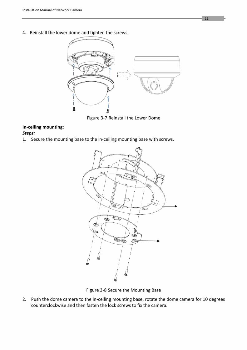
4. Reinstall the lower dome and tighten the screws.
Figure 3-7 Reinstall the Lower Dome
In-ceiling mounting: Steps: 1. Secure the mounting base to the in-ceiling mounting base with screws.
Figure 3-8 Secure the Mounting Base
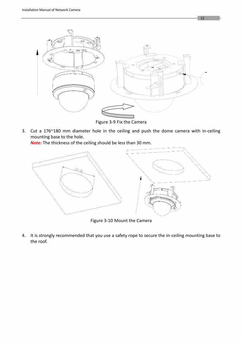
2. Push the dome camera to the in-ceiling mounting base, rotate the dome camera for 10 degrees counterclockwise and then fasten the lock screws to fix the camera.
Installation Manual of Network Camera
12
Figure 3-9 Fix the Camera
3. Cut a 176~180 mm diameter hole in the ceiling and push the dome camera with in-ceiling mounting base to the hole. Note: The thickness of the ceiling should be less than 30 mm.
Figure 3-10 Mount the Camera
4. It is strongly recommended that you use a safety rope to secure the in-ceiling mounting base to
the roof.
Installation Manual of Network Camera
13
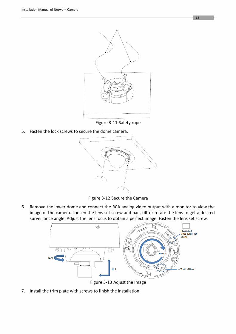
Figure 3-11 Safety rope
5. Fasten the lock screws to secure the dome camera.
Figure 3-12 Secure the Camera
6. Remove the lower dome and connect the RCA analog video output with a monitor to view the image of the camera. Loosen the lens set screw and pan, tilt or rotate the lens to get a desired surveillance angle. Adjust the lens focus to obtain a perfect image. Fasten the lens set screw.
Figure 3-13 Adjust the Image
7. Install the trim plate with screws to finish the installation.
Installation Manual of Network Camera
14
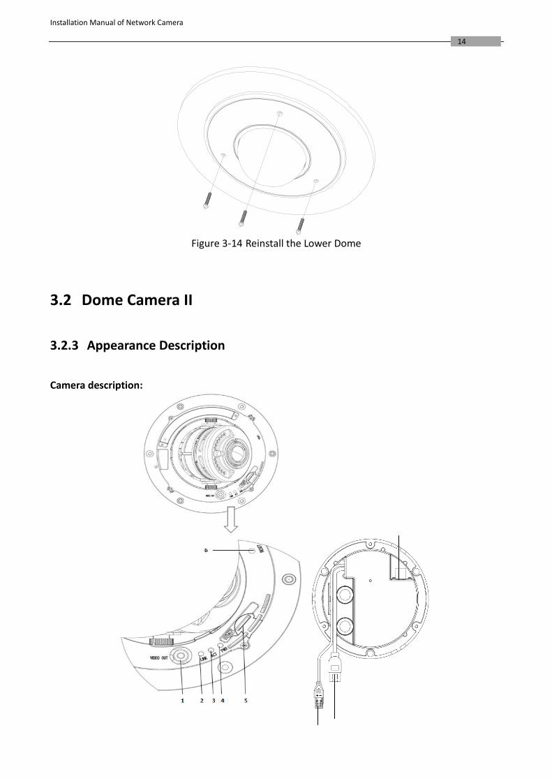
Figure 3-14 Reinstall the Lower Dome
3.2 Dome Camera II
3.2.3 Appearance Description
Camera description:
Installation Manual of Network Camera
15
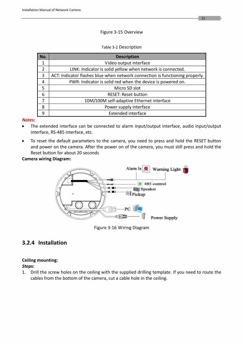
Figure 3-15 Overview
Table 3-2 Description
No. Description
1 Video output interface
2 LINK: Indicator is solid yellow when network is connected.
3 ACT: Indicator flashes blue when network connection is functioning properly.
4 PWR: Indicator is solid red when the device is powered on.
5 Micro SD slot
6 RESET: Reset button
7 10M/100M self-adaptive Ethernet interface
8 Power supply interface
9 Extended interface
Notes:
The extended interface can be connected to alarm input/output interface, audio input/output interface, RS-485 interface, etc.
To reset the default parameters to the camera, you need to press and hold the RESET button and power on the camera. After the power on of the camera, you must still press and hold the Reset button for about 20 seconds
Camera wiring Diagram:
Figure 3-16 Wiring Diagram
3.2.4 Installation
Ceiling mounting: Steps: 1. Drill the screw holes on the ceiling with the supplied drilling template. If you need to route the
cables from the bottom of the camera, cut a cable hole in the ceiling.
Installation Manual of Network Camera
16
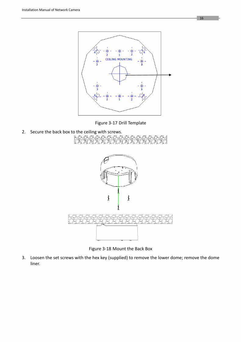
Figure 3-17 Drill Template
2. Secure the back box to the ceiling with screws.
Figure 3-18 Mount the Back Box
3. Loosen the set screws with the hex key (supplied) to remove the lower dome; remove the dome liner.
Installation Manual of Network Camera
17
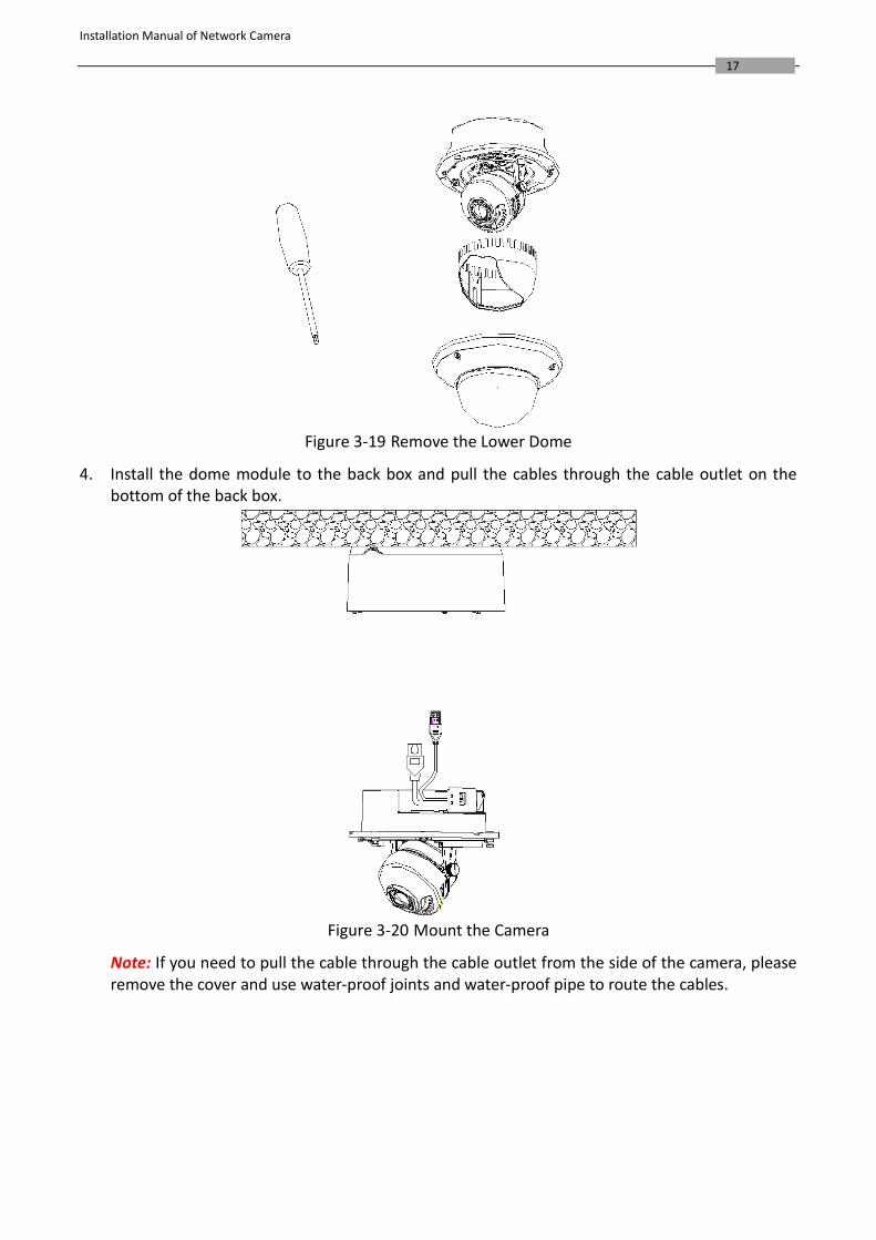
Figure 3-19 Remove the Lower Dome
4. Install the dome module to the back box and pull the cables through the cable outlet on the bottom of the back box.
Figure 3-20 Mount the Camera
Note: If you need to pull the cable through the cable outlet from the side of the camera, please remove the cover and use water-proof joints and water-proof pipe to route the cables.
Installation Manual of Network Camera
18
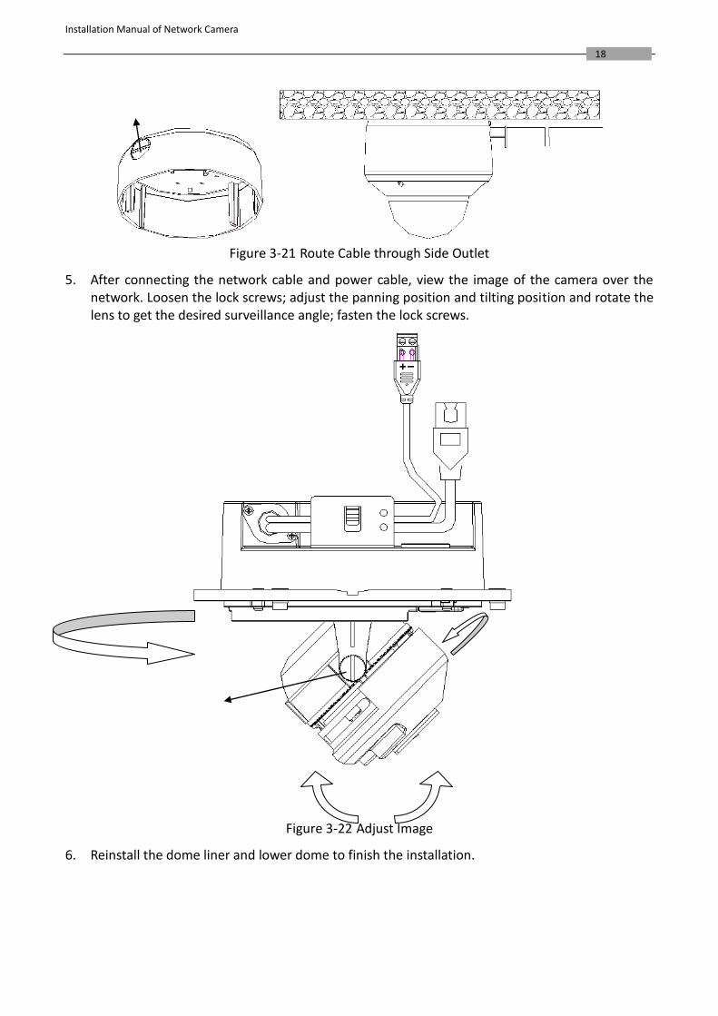
Figure 3-21 Route Cable through Side Outlet
5. After connecting the network cable and power cable, view the image of the camera over the network. Loosen the lock screws; adjust the panning position and tilting position and rotate the lens to get the desired surveillance angle; fasten the lock screws.
Figure 3-22 Adjust Image
6. Reinstall the dome liner and lower dome to finish the installation.
Installation Manual of Network Camera
19
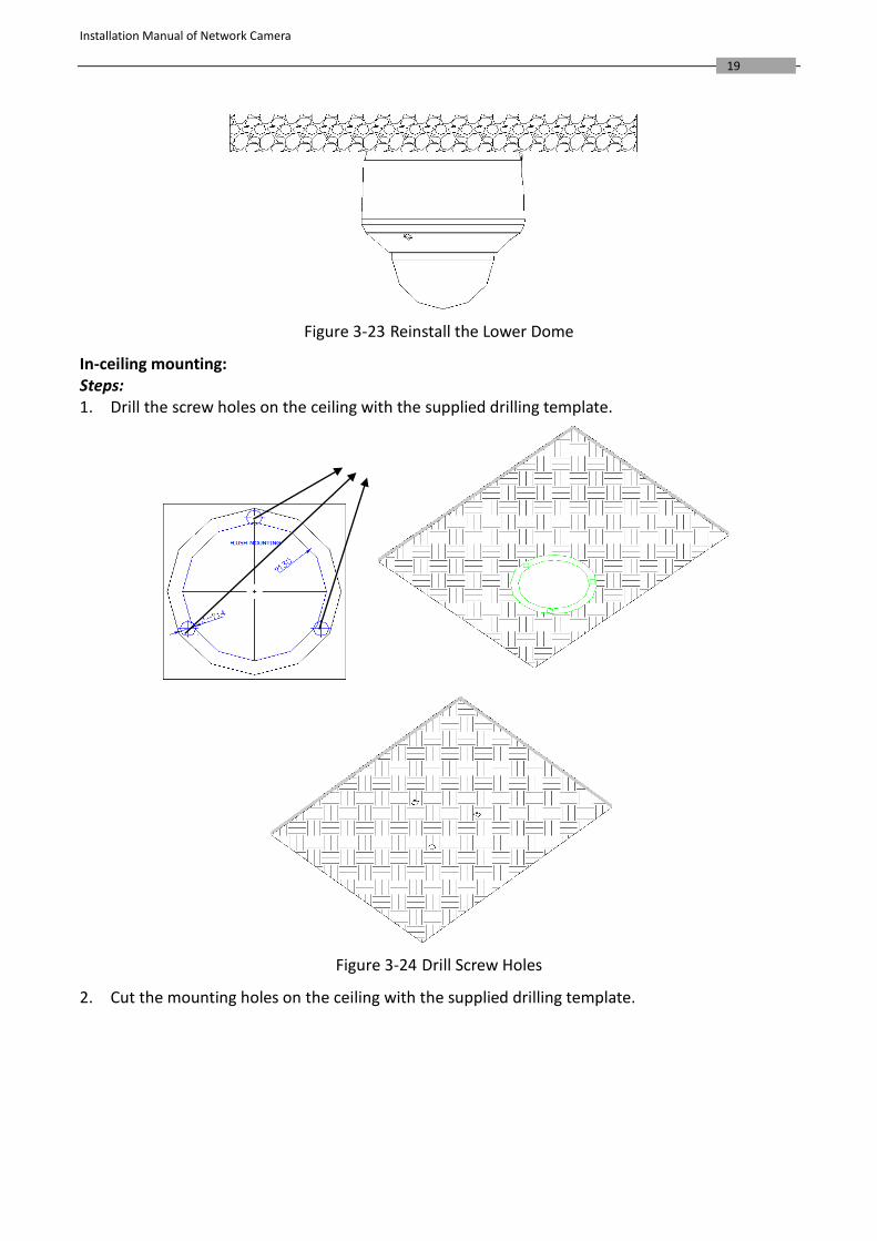
Figure 3-23 Reinstall the Lower Dome
In-ceiling mounting: Steps: 1. Drill the screw holes on the ceiling with the supplied drilling template.
Figure 3-24 Drill Screw Holes
2. Cut the mounting holes on the ceiling with the supplied drilling template.
Installation Manual of Network Camera
20
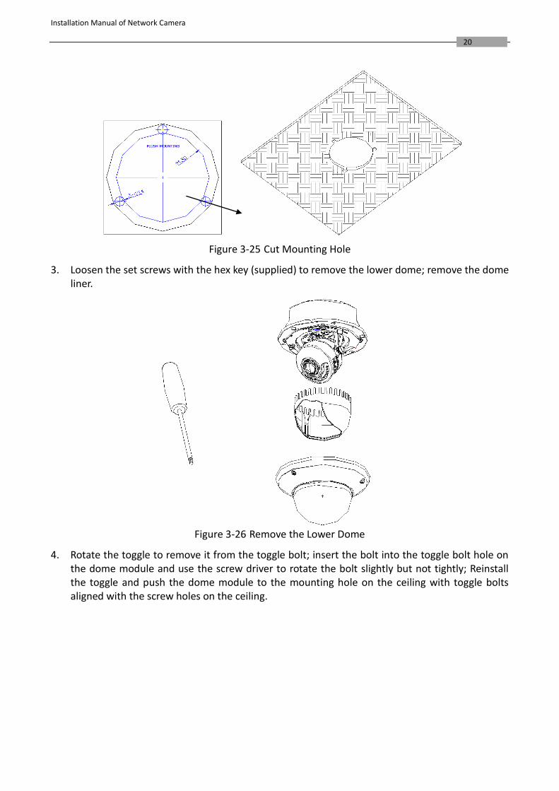
Figure 3-25 Cut Mounting Hole
3. Loosen the set screws with the hex key (supplied) to remove the lower dome; remove the dome liner.
Figure 3-26 Remove the Lower Dome
4. Rotate the toggle to remove it from the toggle bolt; insert the bolt into the toggle bolt hole on the dome module and use the screw driver to rotate the bolt slightly but not tightly; Reinstall the toggle and push the dome module to the mounting hole on the ceiling with toggle bolts aligned with the screw holes on the ceiling.
Installation Manual of Network Camera
21
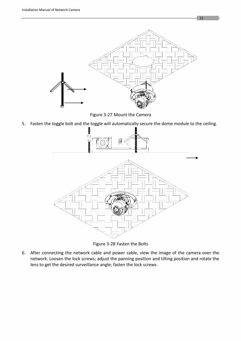
Figure 3-27 Mount the Camera
5. Fasten the toggle bolt and the toggle will automatically secure the dome module to the ceiling.
Figure 3-28 Fasten the Bolts
6. After connecting the network cable and power cable, view the image of the camera over the network. Loosen the lock screws; adjust the panning position and tilting position and rotate the lens to get the desired surveillance angle; fasten the lock screws.
Installation Manual of Network Camera
22
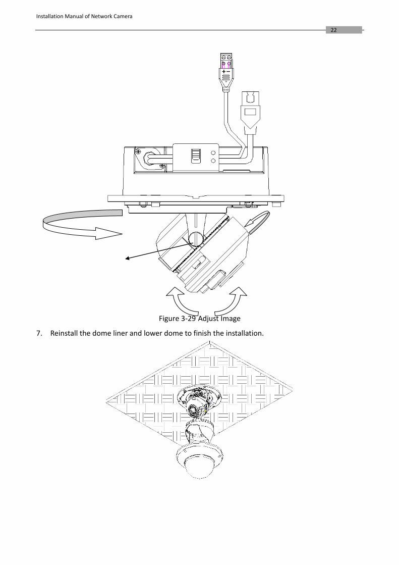
Figure 3-29 Adjust Image
7. Reinstall the dome liner and lower dome to finish the installation.
Installation Manual of Network Camera
23
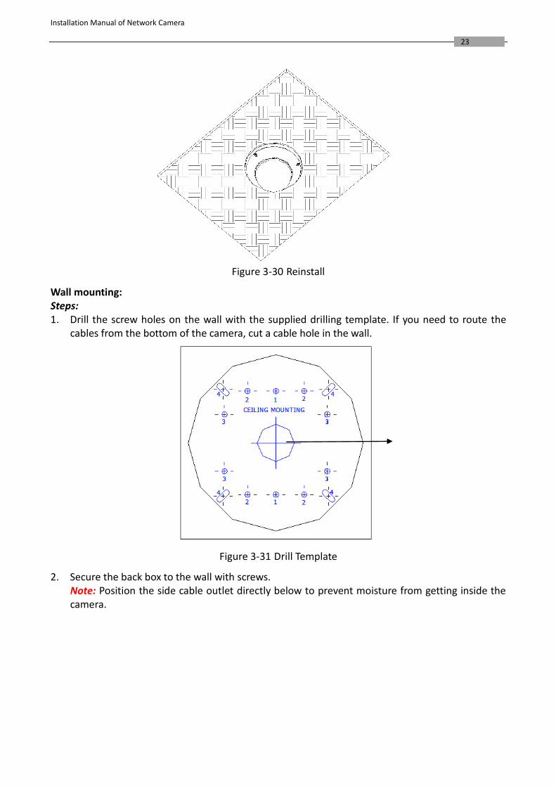
Figure 3-30 Reinstall
Wall mounting: Steps: 1. Drill the screw holes on the wall with the supplied drilling template. If you need to route the
cables from the bottom of the camera, cut a cable hole in the wall.
Figure 3-31 Drill Template
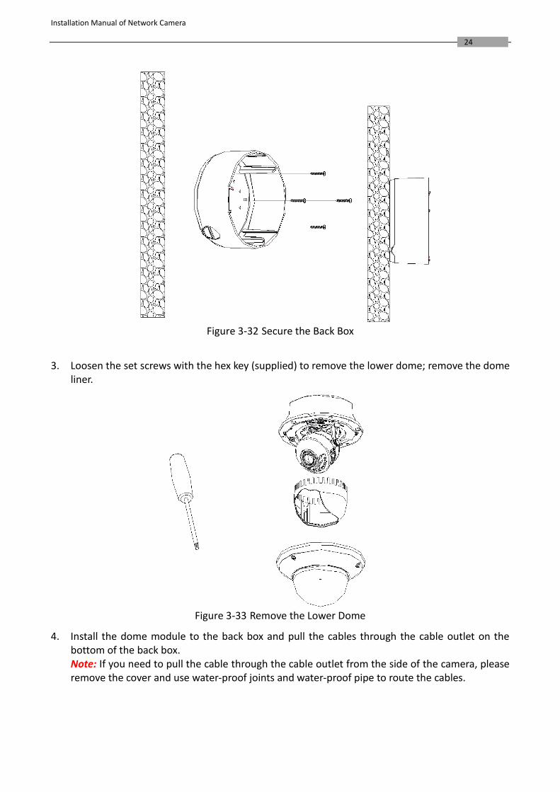
2. Secure the back box to the wall with screws. Note: Position the side cable outlet directly below to prevent moisture from getting inside the camera.
Installation Manual of Network Camera
24
Figure 3-32 Secure the Back Box
3. Loosen the set screws with the hex key (supplied) to remove the lower dome; remove the dome
liner.
Figure 3-33 Remove the Lower Dome
4. Install the dome module to the back box and pull the cables through the cable outlet on the bottom of the back box. Note: If you need to pull the cable through the cable outlet from the side of the camera, please remove the cover and use water-proof joints and water-proof pipe to route the cables.
Installation Manual of Network Camera
25
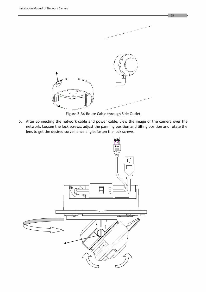
Figure 3-34 Route Cable through Side Outlet
5. After connecting the network cable and power cable, view the image of the camera over the network. Loosen the lock screws; adjust the panning position and tilting position and rotate the lens to get the desired surveillance angle; fasten the lock screws.
Installation Manual of Network Camera
26
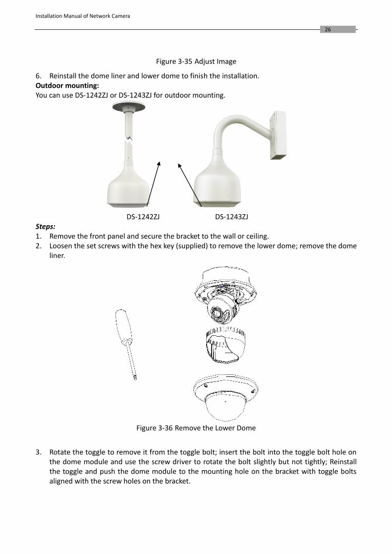
Figure 3-35 Adjust Image
6. Reinstall the dome liner and lower dome to finish the installation. Outdoor mounting: You can use DS-1242ZJ or DS-1243ZJ for outdoor mounting.
DS-1242ZJ DS-1243ZJ Steps: 1. Remove the front panel and secure the bracket to the wall or ceiling. 2. Loosen the set screws with the hex key (supplied) to remove the lower dome; remove the dome
liner.
Figure 3-36 Remove the Lower Dome
3. Rotate the toggle to remove it from the toggle bolt; insert the bolt into the toggle bolt hole on
the dome module and use the screw driver to rotate the bolt slightly but not tightly; Reinstall the toggle and push the dome module to the mounting hole on the bracket with toggle bolts aligned with the screw holes on the bracket.
Installation Manual of Network Camera
27
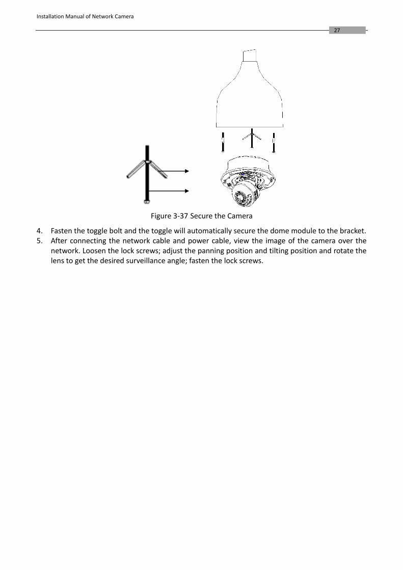
Figure 3-37 Secure the Camera
4. Fasten the toggle bolt and the toggle will automatically secure the dome module to the bracket. 5. After connecting the network cable and power cable, view the image of the camera over the
network. Loosen the lock screws; adjust the panning position and tilting position and rotate the lens to get the desired surveillance angle; fasten the lock screws.
Installation Manual of Network Camera
28
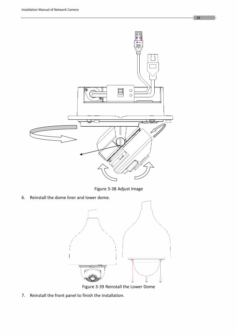
Figure 3-38 Adjust Image
6. Reinstall the dome liner and lower dome.
Figure 3-39 Reinstall the Lower Dome
7. Reinstall the front panel to finish the installation.
Installation Manual of Network Camera
29
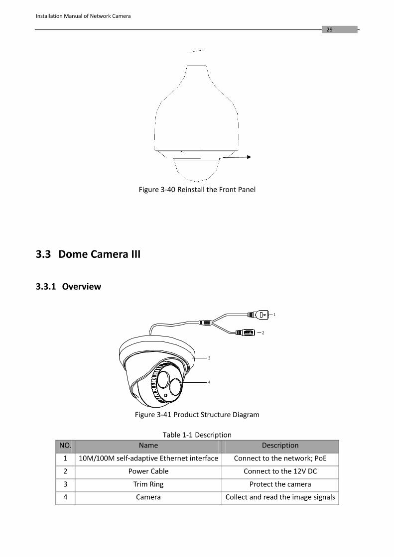
Figure 3-40 Reinstall the Front Panel
3.3 Dome Camera III
3.3.1 Overview
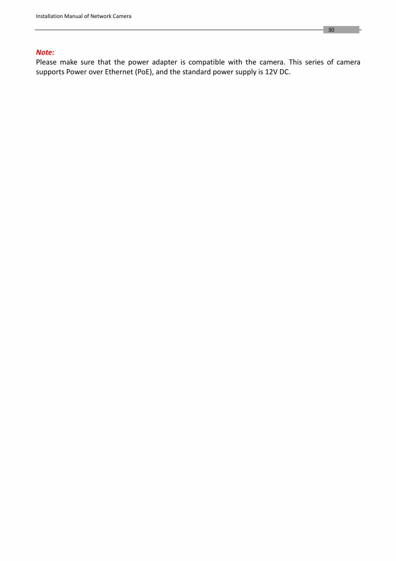
Figure 3-41 Product Structure Diagram
Table 1-1 Description
NO. Name Description
1 10M/100M self-adaptive Ethernet interface Connect to the network; PoE
2 Power Cable Connect to the 12V DC
3 Trim Ring Protect the camera
4 Camera Collect and read the image signals
Installation Manual of Network Camera
30
Note: Please make sure that the power adapter is compatible with the camera. This series of camera supports Power over Ethernet (PoE), and the standard power supply is 12V DC.
Installation Manual of Network Camera
31
3.3.2 Installation
Before you start, please verify the package contents are correct by checking the items against the
packing list, and make sure all the components are included.
Wall mounting is preferred. We will take wall mounting as an example to explain the installation
steps in this section.
Note:
Please make sure that the wall is strong enough to withstand three times the weight of the camera.
Steps:
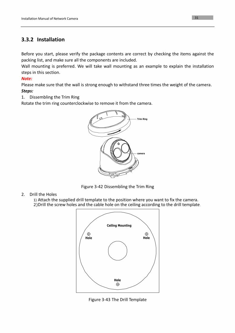
1. Dissembling the Trim Ring
Rotate the trim ring counterclockwise to remove it from the camera.
Figure 3-42 Dissembling the Trim Ring
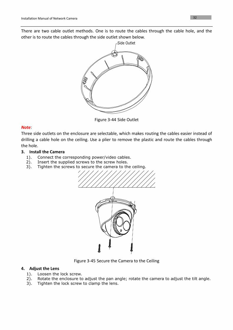
2. Drill the Holes 1) Attach the supplied drill template to the position where you want to fix the camera. 2) Drill the screw holes and the cable hole on the ceiling according to the drill template.
Figure 3-43 The Drill Template
Installation Manual of Network Camera
32
There are two cable outlet methods. One is to route the cables through the cable hole, and the
other is to route the cables through the side outlet shown below.
Figure 3-44 Side Outlet
Note:
Three side outlets on the enclosure are selectable, which makes routing the cables easier instead of
drilling a cable hole on the ceiling. Use a plier to remove the plastic and route the cables through
the hole.
3. Install the Camera 1). Connect the corresponding power/video cables.
2). Insert the supplied screws to the screw holes. 3). Tighten the screws to secure the camera to the ceiling.
Figure 3-45 Secure the Camera to the Ceiling
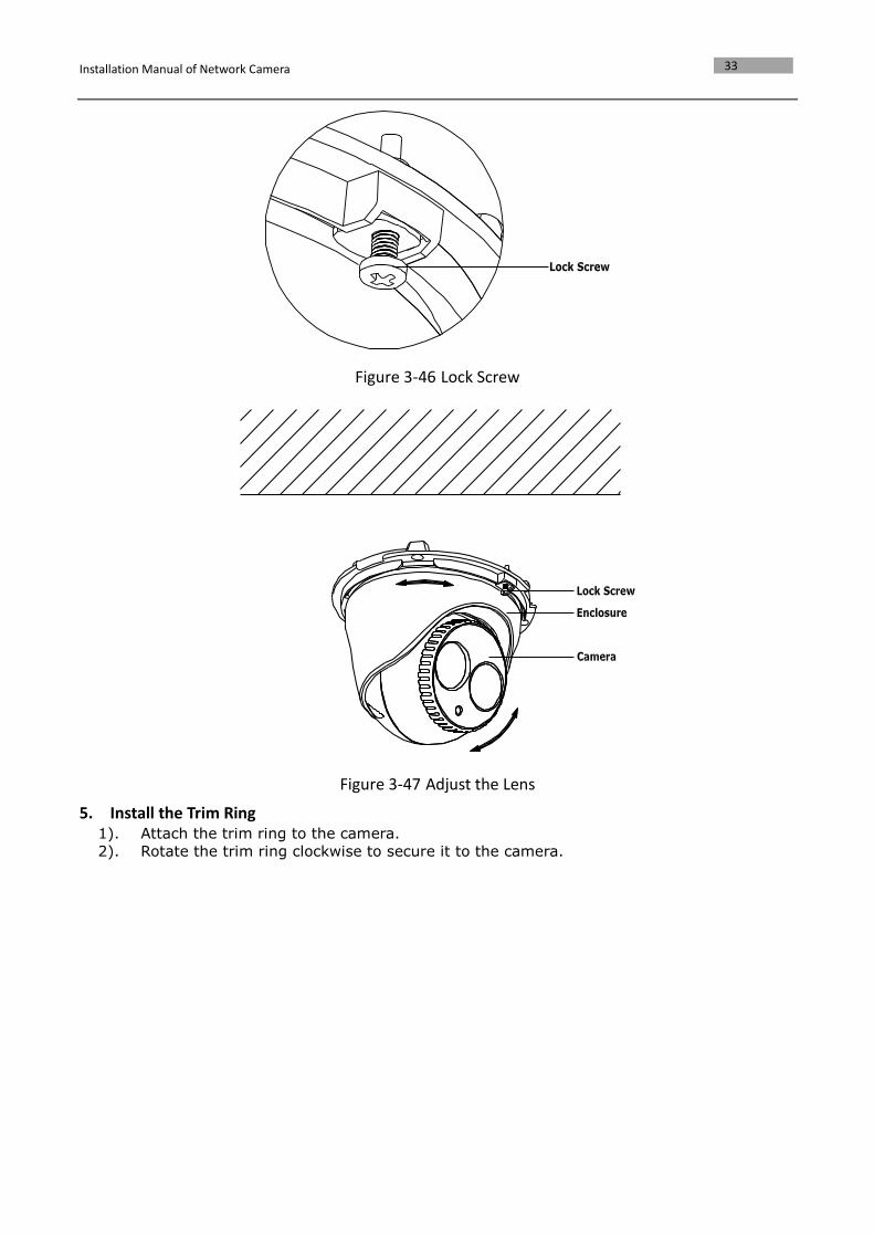
4. Adjust the Lens 1). Loosen the lock screw. 2). Rotate the enclosure to adjust the pan angle; rotate the camera to adjust the tilt angle. 3). Tighten the lock screw to clamp the lens.
Installation Manual of Network Camera
33
Figure 3-46 Lock Screw
Figure 3-47 Adjust the Lens
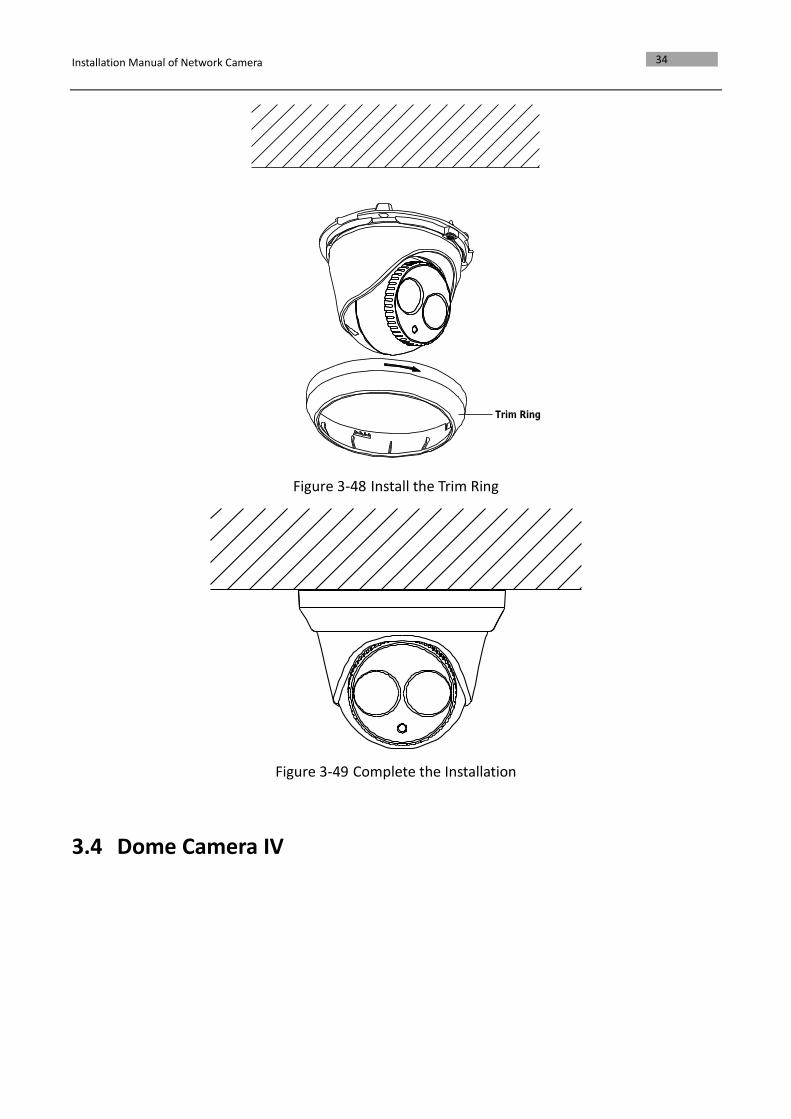
5. Install the Trim Ring 1). Attach the trim ring to the camera.
2). Rotate the trim ring clockwise to secure it to the camera.
Installation Manual of Network Camera
34
Figure 3-48 Install the Trim Ring
Figure 3-49 Complete the Installation
3.4 Dome Camera IV
Installation Manual of Network Camera
35
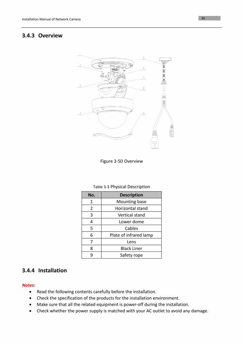
3.4.3 Overview
Figure 3-50 Overview
Table 3-3 Physical Description
No. Description
1 Mounting base
2 Horizontal stand
3 Vertical stand
4 Lower dome
5 Cables
6 Plate of infrared lamp
7 Lens
8 Black Liner
9 Safety rope
3.4.4 Installation
Notes:
Read the following contents carefully before the installation.
Check the specification of the products for the installation environment.
Make sure that all the related equipment is power-off during the installation.
Check whether the power supply is matched with your AC outlet to avoid any damage.
Installation Manual of Network Camera
36
Do not place the camera in extremely hot or damp environment. To avoid heat accumulation,
good ventilation is required for a proper operating environment.
If the product does not function properly, please contact your dealer or the nearest service
center. Do not disassemble the camera for repair or maintenance by yourself.
Ceiling mounting is recommended for this camera.
Note: The ceiling must be thick enough to withstand more than three times the weight of the
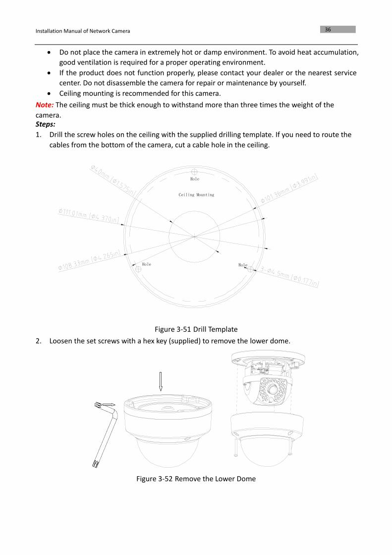
camera. Steps:
1. Drill the screw holes on the ceiling with the supplied drilling template. If you need to route the
cables from the bottom of the camera, cut a cable hole in the ceiling.
Figure 3-51 Drill Template
2. Loosen the set screws with a hex key (supplied) to remove the lower dome.
Figure 3-52 Remove the Lower Dome
Hole
Hole Hole
Ceiling Mounting
Installation Manual of Network Camera
37
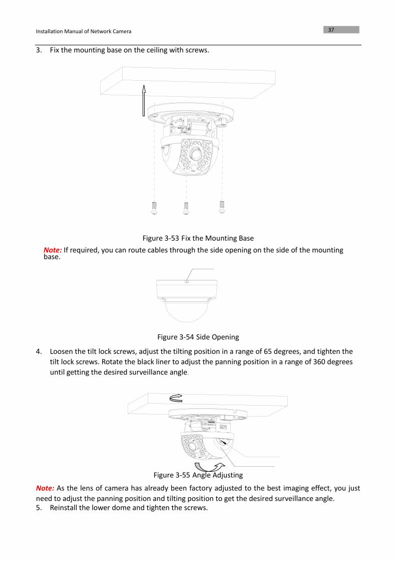
3. Fix the mounting base on the ceiling with screws.
Figure 3-53 Fix the Mounting Base
Note: If required, you can route cables through the side opening on the side of the mounting base.
Figure 3-54 Side Opening
4. Loosen the tilt lock screws, adjust the tilting position in a range of 65 degrees, and tighten the
tilt lock screws. Rotate the black liner to adjust the panning position in a range of 360 degrees
until getting the desired surveillance angle.
Figure 3-55 Angle Adjusting
Note: As the lens of camera has already been factory adjusted to the best imaging effect, you just
need to adjust the panning position and tilting position to get the desired surveillance angle. 5. Reinstall the lower dome and tighten the screws.
Installation Manual of Network Camera
38
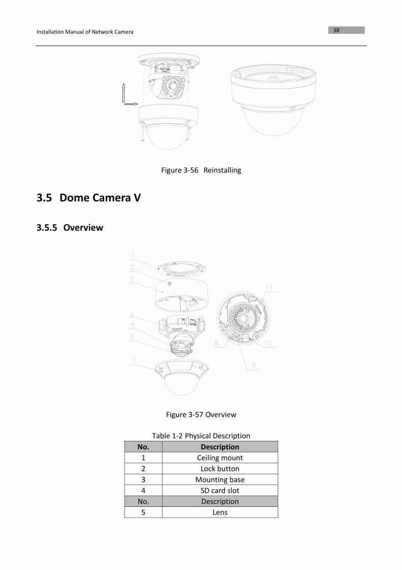
Figure 3-56 Reinstalling
3.5 Dome Camera V
3.5.5 Overview
Figure 3-57 Overview
Table 1-2 Physical Description
No. Description
1 Ceiling mount
2 Lock button
3 Mounting base
4 SD card slot
No. Description
5 Lens
Installation Manual of Network Camera
39
6 Infrared lamp
7 Lower dome
8 Status indicator
9 RCA analog video output
10 Debug
11 Reset
Note:
After the power-on of the camera, pressing and holding the RESET button for about 10 seconds can
reset all the parameters to the default settings.
3.5.6 Installation
Notes:
Read the following contents carefully before the installation.
Check the specification of the products for the installation environment.
Make sure that all the related equipment is power-off during the installation.
Check whether the power supply is matched with your AC outlet to avoid any damage.
Do not place the camera in extremely hot or damp environment. To avoid heat accumulation,
good ventilation is required for a proper operating environment.
If the product does not function properly, please contact your dealer or the nearest service
center. Do not disassemble the camera for repair or maintenance by yourself.
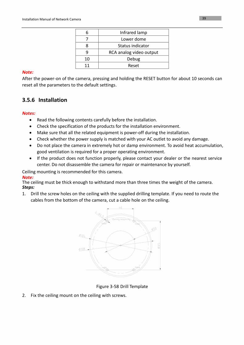
Ceiling mounting is recommended for this camera. Note: The ceiling must be thick enough to withstand more than three times the weight of the camera. Steps:
1. Drill the screw holes on the ceiling with the supplied drilling template. If you need to route the
cables from the bottom of the camera, cut a cable hole on the ceiling.
Figure 3-58 Drill Template
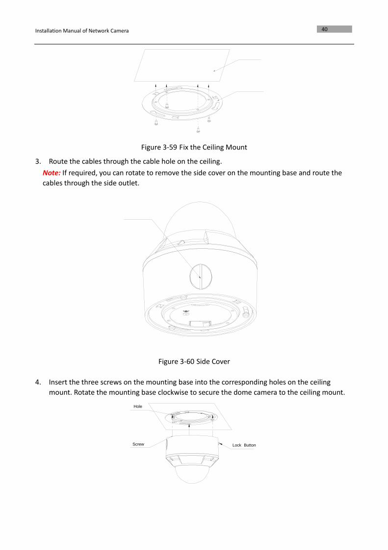
2. Fix the ceiling mount on the ceiling with screws.
Installation Manual of Network Camera
40
Figure 3-59 Fix the Ceiling Mount
3. Route the cables through the cable hole on the ceiling.
Note: If required, you can rotate to remove the side cover on the mounting base and route the
cables through the side outlet.
Figure 3-60 Side Cover
4. Insert the three screws on the mounting base into the corresponding holes on the ceiling
mount. Rotate the mounting base clockwise to secure the dome camera to the ceiling mount.
Lock Button Screw
Hole
Installation Manual of Network Camera
41
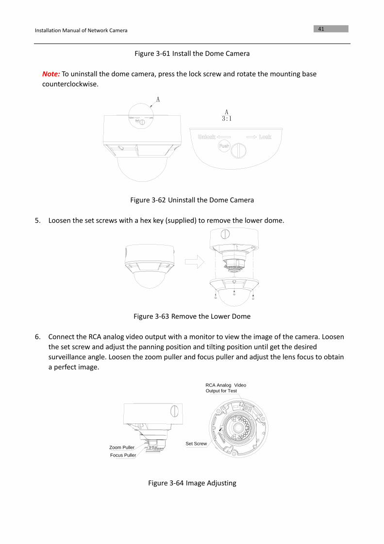
Figure 3-61 Install the Dome Camera
Note: To uninstall the dome camera, press the lock screw and rotate the mounting base
counterclockwise.
A3:1
A
Figure 3-62 Uninstall the Dome Camera
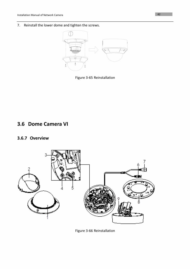
5. Loosen the set screws with a hex key (supplied) to remove the lower dome.
Figure 3-63 Remove the Lower Dome
6. Connect the RCA analog video output with a monitor to view the image of the camera. Loosen
the set screw and adjust the panning position and tilting position until get the desired
surveillance angle. Loosen the zoom puller and focus puller and adjust the lens focus to obtain
a perfect image.
RCA Analog Video
Output for Test
Set ScrewZoom Puller
Focus Puller
Figure 3-64 Image Adjusting
Installation Manual of Network Camera
42
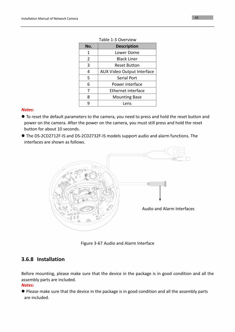
7. Reinstall the lower dome and tighten the screws.
Figure 3-65 Reinstallation
3.6 Dome Camera VI
3.6.7 Overview
Figure 3-66 Reinstallation
Installation Manual of Network Camera
43
Table 1-3 Overview
No. Description
1 Lower Dome
2 Black Liner
3 Reset Button
4 AUX Video Output Interface
5 Serial Port
6 Power interface
7 Ethernet interface
8 Mounting Base
9 Lens
Notes:
To reset the default parameters to the camera, you need to press and hold the reset button and
power on the camera. After the power on the camera, you must still press and hold the reset
button for about 10 seconds.
The DS-2CD2712F-IS and DS-2CD2732F-IS models support audio and alarm functions. The
interfaces are shown as follows.
Figure 3-67 Audio and Alarm Interface
3.6.8 Installation
Before mounting, please make sure that the device in the package is in good condition and all the
assembly parts are included. Notes:
Please make sure that the device in the package is in good condition and all the assembly parts
are included.
Audio and Alarm Interfaces
Installation Manual of Network Camera
44
Check the specification of the products for the installation environment.
Make sure that all the related equipment is power-off during the installation.
Check whether the power supply is matched with your AC outlet to avoid any damage.
If the product does not function properly, please contact your dealer or the nearest service center.
Do not disassemble the camera for repair or maintenance by yourself.
Please make sure that the wall is strong enough to withstand three times the weight of the
camera.
Disassembling
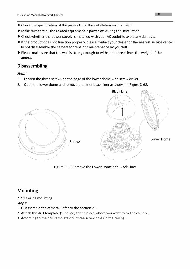
Steps:
1. Loosen the three screws on the edge of the lower dome with screw driver.
2. Open the lower dome and remove the inner black liner as shown in Figure 3-68.
Figure 3-68 Remove the Lower Dome and Black Liner
Mounting
2.2.1 Ceiling mounting
Steps:
1. Disassemble the camera. Refer to the section 2.1.
2. Attach the drill template (supplied) to the place where you want to fix the camera.
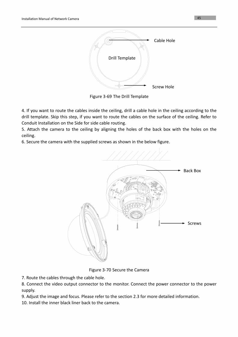
3. According to the drill template drill three screw holes in the ceiling.
Screws
Black Liner
Lower Dome
Installation Manual of Network Camera
45
Figure 3-69 The Drill Template
4. If you want to route the cables inside the ceiling, drill a cable hole in the ceiling according to the
drill template. Skip this step, if you want to route the cables on the surface of the ceiling. Refer to
Conduit Installation on the Side for side cable routing.
5. Attach the camera to the ceiling by aligning the holes of the back box with the holes on the
ceiling.
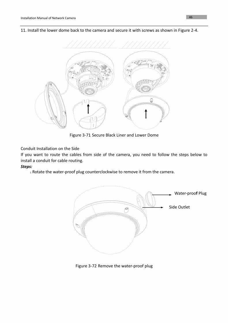
6. Secure the camera with the supplied screws as shown in the below figure.
Figure 3-70 Secure the Camera
7. Route the cables through the cable hole.
8. Connect the video output connector to the monitor. Connect the power connector to the power
supply.
9. Adjust the image and focus. Please refer to the section 2.3 for more detailed information.
10. Install the inner black liner back to the camera.
Drill Template
Screw Hole
Cable Hole
Back Box
Screws
Installation Manual of Network Camera
46
11. Install the lower dome back to the camera and secure it with screws as shown in Figure 2-4.
Figure 3-71 Secure Black Liner and Lower Dome
Conduit Installation on the Side
If you want to route the cables from side of the camera, you need to follow the steps below to
install a conduit for cable routing.
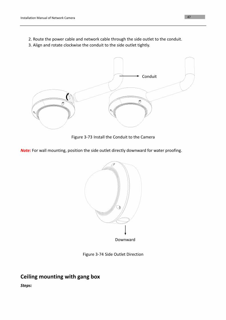
Steps: 1. Rotate the water-proof plug counterclockwise to remove it from the camera.
Figure 3-72 Remove the water-proof plug
Water-proof Plug
Side Outlet
Installation Manual of Network Camera
47
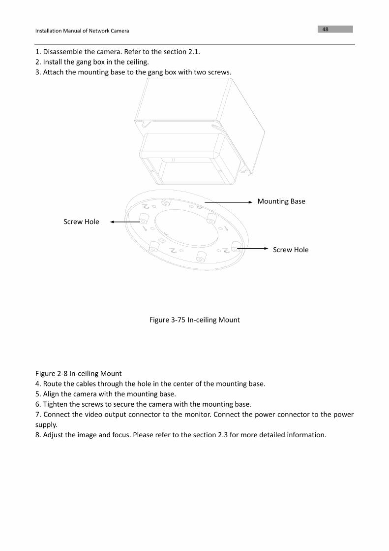
2. Route the power cable and network cable through the side outlet to the conduit.
3. Align and rotate clockwise the conduit to the side outlet tightly.
Figure 3-73 Install the Conduit to the Camera
Note: For wall mounting, position the side outlet directly downward for water proofing.
Figure 3-74 Side Outlet Direction
Ceiling mounting with gang box
Steps:
Conduit
Downward
Installation Manual of Network Camera
48
1. Disassemble the camera. Refer to the section 2.1.
2. Install the gang box in the ceiling.
3. Attach the mounting base to the gang box with two screws.
Figure 3-75 In-ceiling Mount
Figure 2-8 In-ceiling Mount
4. Route the cables through the hole in the center of the mounting base.
5. Align the camera with the mounting base.
6. Tighten the screws to secure the camera with the mounting base.
7. Connect the video output connector to the monitor. Connect the power connector to the power
supply.
8. Adjust the image and focus. Please refer to the section 2.3 for more detailed information.
Screw Hole
Screw Hole
Mounting Base
Installation Manual of Network Camera
49
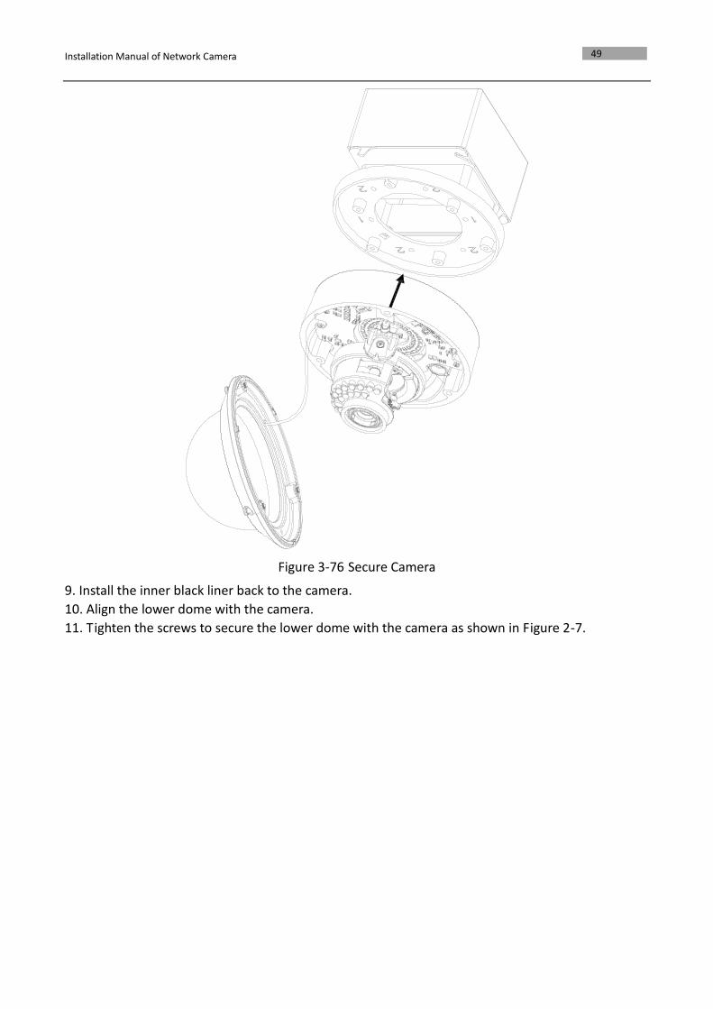
Figure 3-76 Secure Camera
9. Install the inner black liner back to the camera.
10. Align the lower dome with the camera.
11. Tighten the screws to secure the lower dome with the camera as shown in Figure 2-7.
Installation Manual of Network Camera
50
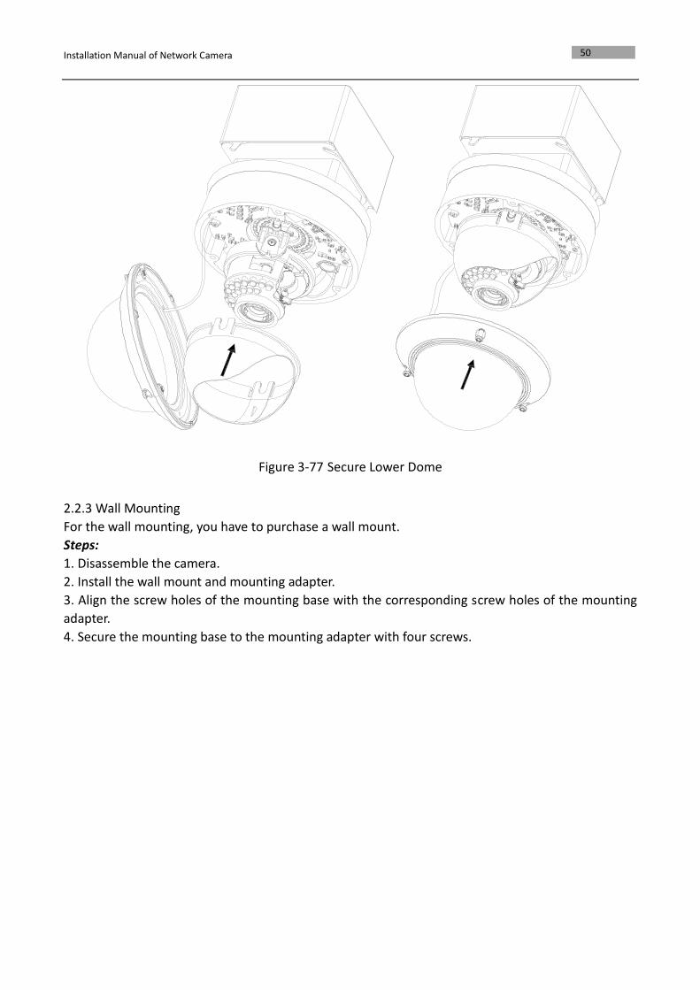
Figure 3-77 Secure Lower Dome
2.2.3 Wall Mounting
For the wall mounting, you have to purchase a wall mount.
Steps:
1. Disassemble the camera.
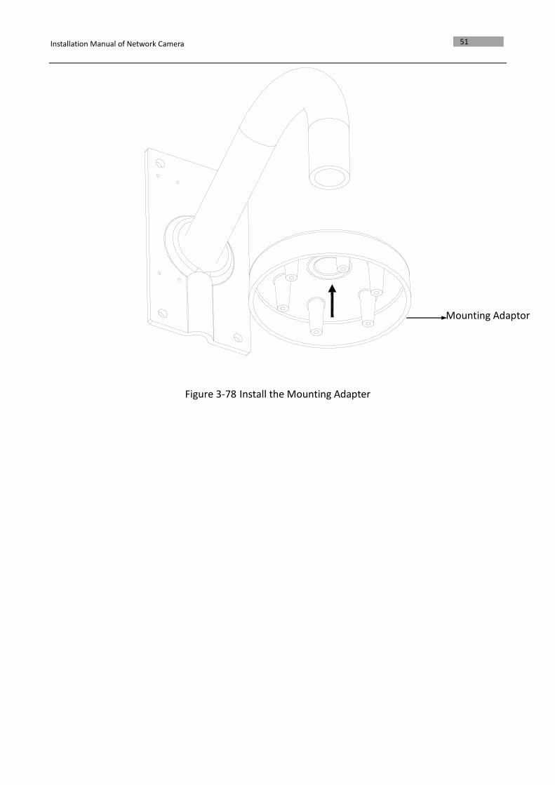
2. Install the wall mount and mounting adapter.
3. Align the screw holes of the mounting base with the corresponding screw holes of the mounting
adapter.
4. Secure the mounting base to the mounting adapter with four screws.
Installation Manual of Network Camera
51
Figure 3-78 Install the Mounting Adapter
Mounting Adaptor
Installation Manual of Network Camera
52
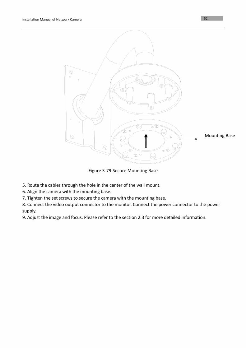
Figure 3-79 Secure Mounting Base
5. Route the cables through the hole in the center of the wall mount.
6. Align the camera with the mounting base.
7. Tighten the set screws to secure the camera with the mounting base.
8. Connect the video output connector to the monitor. Connect the power connector to the power
supply.
9. Adjust the image and focus. Please refer to the section 2.3 for more detailed information.
Mounting Base
Installation Manual of Network Camera
53
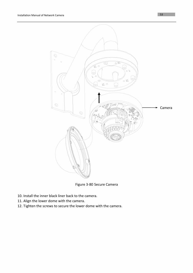
Figure 3-80 Secure Camera
10. Install the inner black liner back to the camera.
11. Align the lower dome with the camera.
12. Tighten the screws to secure the lower dome with the camera.
Camera
Installation Manual of Network Camera
54
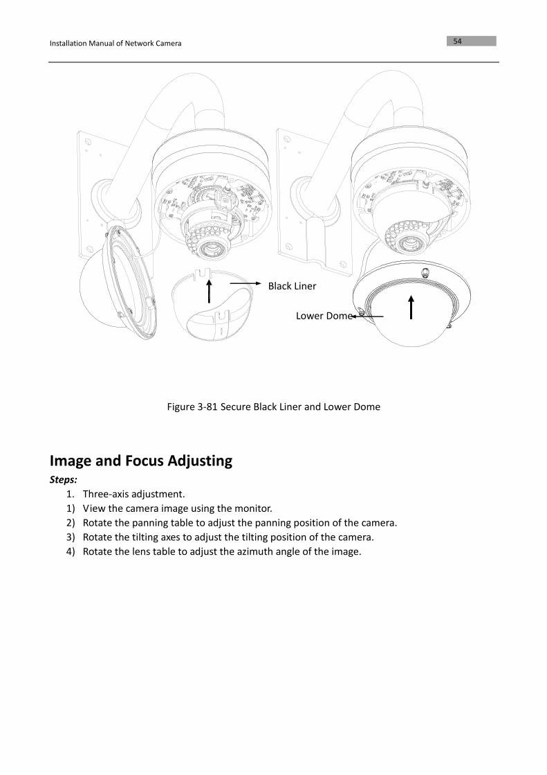
Figure 3-81 Secure Black Liner and Lower Dome
Image and Focus Adjusting Steps:
1. Three-axis adjustment.
1) View the camera image using the monitor.
2) Rotate the panning table to adjust the panning position of the camera.
3) Rotate the tilting axes to adjust the tilting position of the camera.
4) Rotate the lens table to adjust the azimuth angle of the image.
Black Liner
Lower Dome
Installation Manual of Network Camera
55
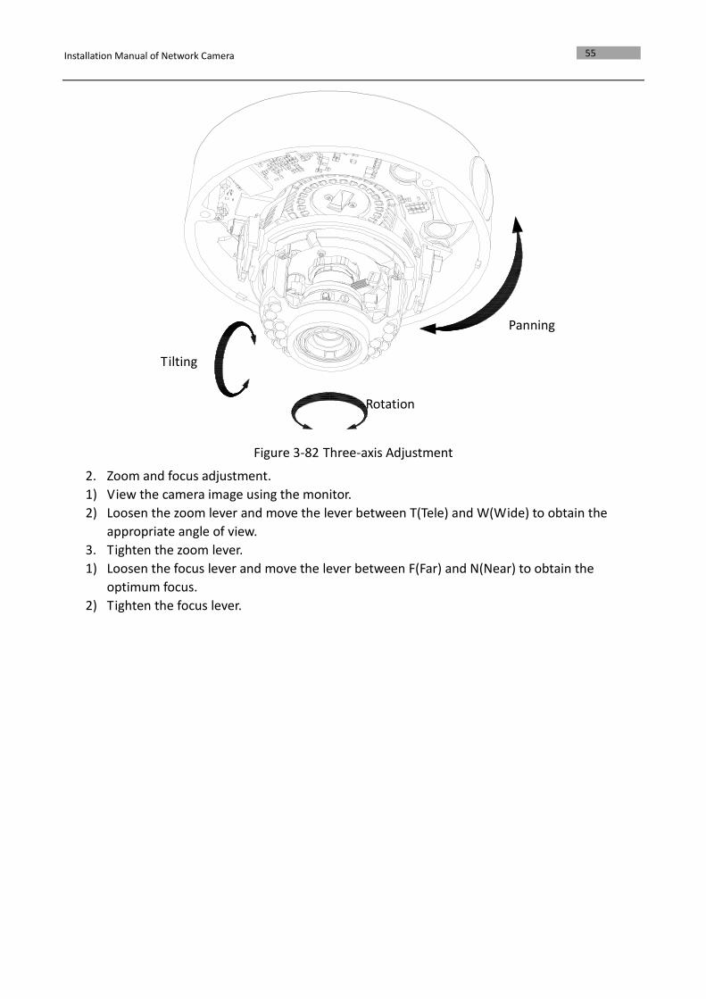
Figure 3-82 Three-axis Adjustment
2. Zoom and focus adjustment.
1) View the camera image using the monitor.
2) Loosen the zoom lever and move the lever between T(Tele) and W(Wide) to obtain the
appropriate angle of view.
3. Tighten the zoom lever.
1) Loosen the focus lever and move the lever between F(Far) and N(Near) to obtain the
optimum focus.
2) Tighten the focus lever.
Panning
Tilting
Rotation
Installation Manual of Network Camera
56
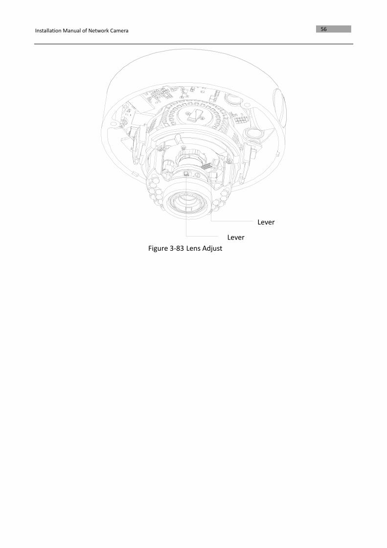
Figure 3-83 Lens Adjustment
Lever
Lever
Installation Manual of Network Camera
57
Chapter 4 Bullet Camera Installation
4.1 Bullet Camera I
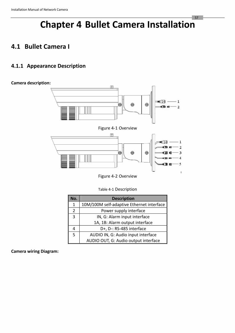
4.1.1 Appearance Description
Camera description:
Figure 4-1 Overview
Figure 4-2 Overview
Table 4-1 Description
No. Description
1 10M/100M self-adaptive Ethernet interface
2 Power supply interface
3 IN, G: Alarm input interface 1A, 1B: Alarm output interface
4 D+, D-: RS-485 interface
5 AUDIO IN, G: Audio input interface AUDIO OUT, G: Audio output interface
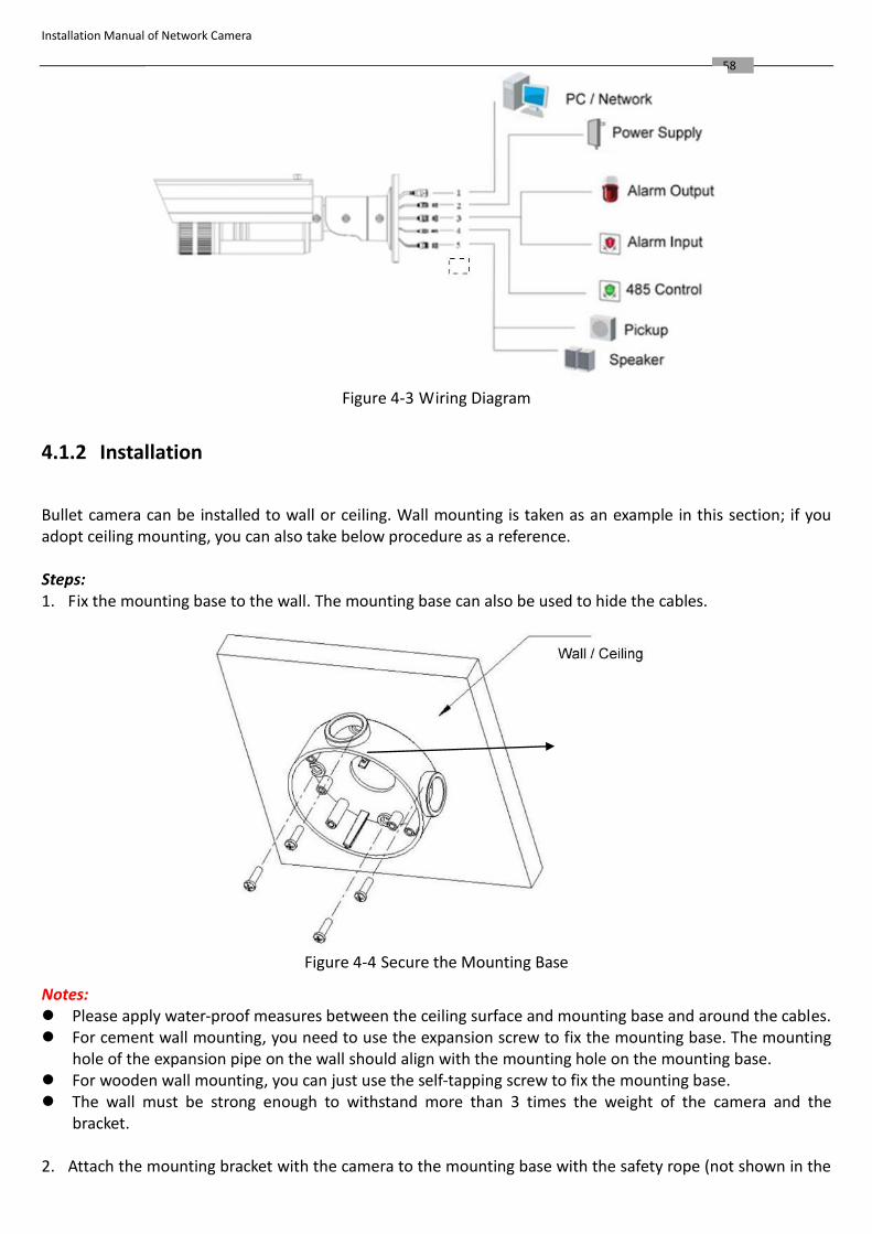
Camera wiring Diagram:
Installation Manual of Network Camera
58
Figure 4-3 Wiring Diagram
4.1.2 Installation
Bullet camera can be installed to wall or ceiling. Wall mounting is taken as an example in this section; if you adopt ceiling mounting, you can also take below procedure as a reference.
Steps: 1. Fix the mounting base to the wall. The mounting base can also be used to hide the cables.
Figure 4-4 Secure the Mounting Base
Notes: Please apply water-proof measures between the ceiling surface and mounting base and around the cables. For cement wall mounting, you need to use the expansion screw to fix the mounting base. The mounting
hole of the expansion pipe on the wall should align with the mounting hole on the mounting base. For wooden wall mounting, you can just use the self-tapping screw to fix the mounting base. The wall must be strong enough to withstand more than 3 times the weight of the camera and the
bracket. 2. Attach the mounting bracket with the camera to the mounting base with the safety rope (not shown in the
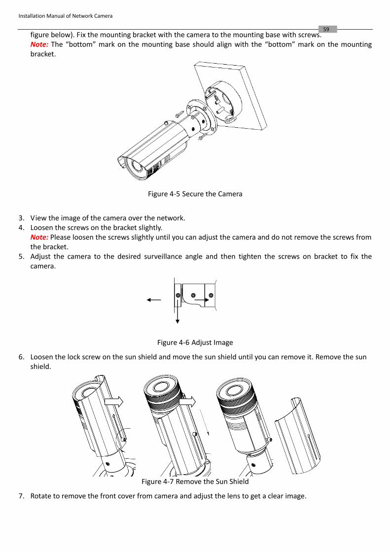
Installation Manual of Network Camera
59 figure below). Fix the mounting bracket with the camera to the mounting base with screws. Note: The “bottom” mark on the mounting base should align with the “bottom” mark on the mounting bracket.
Figure 4-5 Secure the Camera
3. View the image of the camera over the network. 4. Loosen the screws on the bracket slightly.
Note: Please loosen the screws slightly until you can adjust the camera and do not remove the screws from the bracket.
5. Adjust the camera to the desired surveillance angle and then tighten the screws on bracket to fix the camera.
Figure 4-6 Adjust Image
6. Loosen the lock screw on the sun shield and move the sun shield until you can remove it. Remove the sun shield.
Figure 4-7 Remove the Sun Shield
7. Rotate to remove the front cover from camera and adjust the lens to get a clear image.
Installation Manual of Network Camera
60
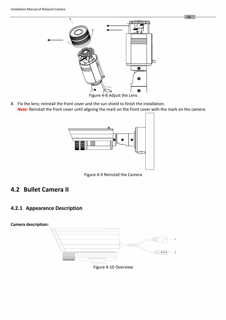
Figure 4-8 Adjust the Lens
8. Fix the lens; reinstall the front cover and the sun shield to finish the installation. Note: Reinstall the front cover until aligning the mark on the front cover with the mark on the camera.
Figure 4-9 Reinstall the Camera
4.2 Bullet Camera II
4.2.1 Appearance Description
Camera description:
2
1
Figure 4-10 Overview
Installation Manual of Network Camera
61
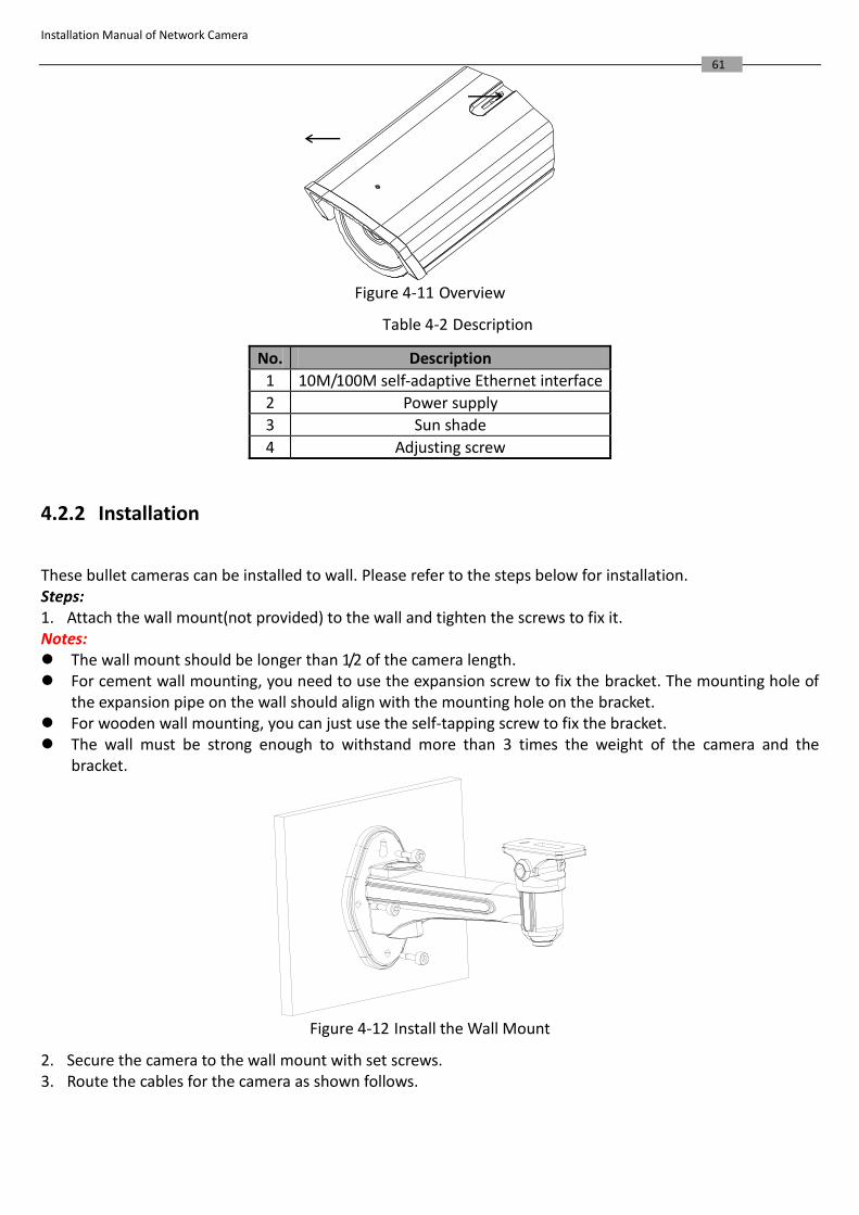
Figure 4-11 Overview
Table 4-2 Description
No. Description
1 10M/100M self-adaptive Ethernet interface
2 Power supply
3 Sun shade
4 Adjusting screw
4.2.2 Installation
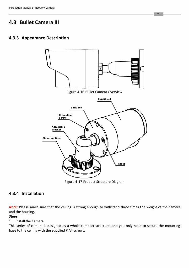
These bullet cameras can be installed to wall. Please refer to the steps below for installation. Steps: 1. Attach the wall mount(not provided) to the wall and tighten the screws to fix it. Notes: The wall mount should be longer than 1/2 of the camera length. For cement wall mounting, you need to use the expansion screw to fix the bracket. The mounting hole of
the expansion pipe on the wall should align with the mounting hole on the bracket. For wooden wall mounting, you can just use the self-tapping screw to fix the bracket. The wall must be strong enough to withstand more than 3 times the weight of the camera and the
bracket.
Figure 4-12 Install the Wall Mount
2. Secure the camera to the wall mount with set screws. 3. Route the cables for the camera as shown follows.

Installation Manual of Network Camera
62
Figure 4-13 Mount the Camera
4. Loosen the panning lock screw, you can adjust the panning angle of the camera up to 360° (Figure 2-9); Loosen the tilting lock screw, you can adjust the tilting angle of the camera up to 90° (Figure 2-10).
Figure 4-14 Panning
Figure 4-15 Tilting
Installation Manual of Network Camera
63
4.3 Bullet Camera III
4.3.3 Appearance Description
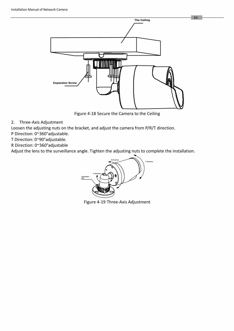
Figure 4-16 Bullet Camera Overview
Sun Shield
Back Box
Adjustable
Bracket
Reset
Grounding
Screw
Figure 4-17 Product Structure Diagram
4.3.4 Installation
Note: Please make sure that the ceiling is strong enough to withstand three times the weight of the camera and the housing. Steps: 1. Install the Camera This series of camera is designed as a whole compact structure, and you only need to secure the mounting base to the ceiling with the supplied P A4 screws.
Installation Manual of Network Camera
64 The Ceiling
Expansion Screw
Figure 4-18 Secure the Camera to the Ceiling
2. Three-Axis Adjustment Loosen the adjusting nuts on the bracket, and adjust the camera from P/R/T direction. P Direction: 0~360°adjustable. T Direction: 0~90°adjustable. R Direction: 0~360°adjustable Adjust the lens to the surveillance angle. Tighten the adjusting nuts to complete the installation.
Adjustable Nut
T Direction
R Direction
P Direction
Figure 4-19 Three-Axis Adjustment
Installation Manual of Network Camera
65
4.4 Bullet Camera IV
4.4.5 Appearance
1
2
3
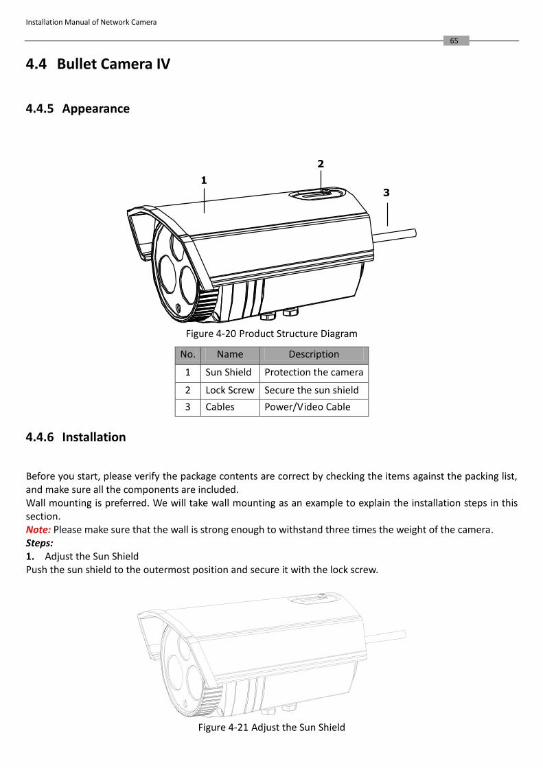
Figure 4-20 Product Structure Diagram
No. Name Description
1 Sun Shield Protection the camera
2 Lock Screw Secure the sun shield
3 Cables Power/Video Cable
4.4.6 Installation
Before you start, please verify the package contents are correct by checking the items against the packing list, and make sure all the components are included. Wall mounting is preferred. We will take wall mounting as an example to explain the installation steps in this section. Note: Please make sure that the wall is strong enough to withstand three times the weight of the camera. Steps: 1. Adjust the Sun Shield Push the sun shield to the outermost position and secure it with the lock screw.
Figure 4-21 Adjust the Sun Shield
Installation Manual of Network Camera
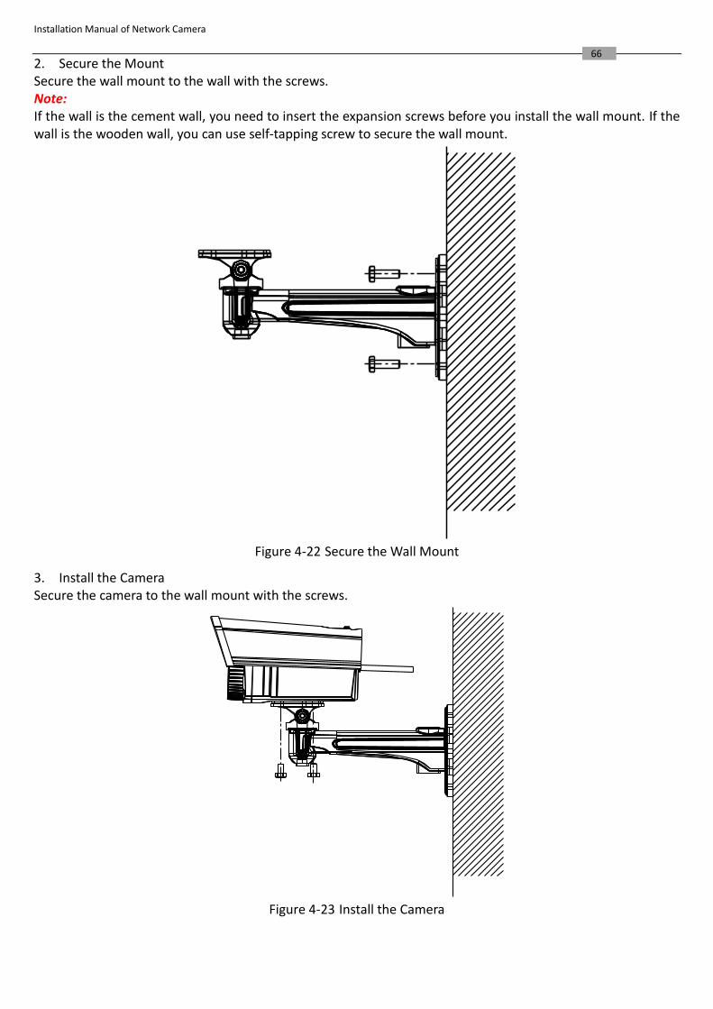
66 2. Secure the Mount Secure the wall mount to the wall with the screws. Note: If the wall is the cement wall, you need to insert the expansion screws before you install the wall mount. If the wall is the wooden wall, you can use self-tapping screw to secure the wall mount.
Figure 4-22 Secure the Wall Mount
3. Install the Camera Secure the camera to the wall mount with the screws.
Figure 4-23 Install the Camera
Installation Manual of Network Camera
67
4.5 Bullet Camera V
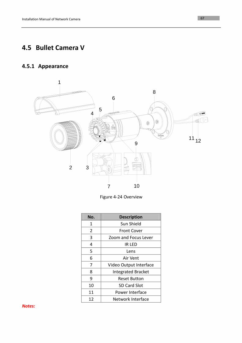
4.5.1 Appearance
54
10
9
7
3
8
6
1
2
1211
Figure 4-24 Overview
No. Description
1 Sun Shield
2 Front Cover
3 Zoom and Focus Lever
4 IR LED
5 Lens
6 Air Vent
7 Video Output Interface
8 Integrated Bracket
9 Reset Button
10 SD Card Slot
11 Power Interface
12 Network Interface
Notes:
Installation Manual of Network Camera
68
To reset the default parameters to the camera, you need to press and hold the reset button and
power on the camera. After the power on the camera, you must still press and hold the reset
button for about 10 seconds.
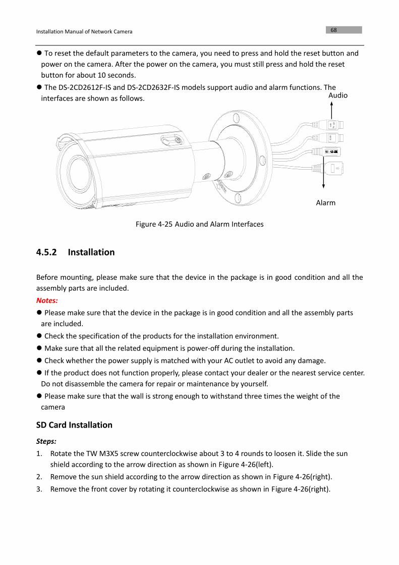
The DS-2CD2612F-IS and DS-2CD2632F-IS models support audio and alarm functions. The
interfaces are shown as follows.
Figure 4-25 Audio and Alarm Interfaces
4.5.2 Installation
Before mounting, please make sure that the device in the package is in good condition and all the
assembly parts are included.
Notes:
Please make sure that the device in the package is in good condition and all the assembly parts
are included.
Check the specification of the products for the installation environment.
Make sure that all the related equipment is power-off during the installation.
Check whether the power supply is matched with your AC outlet to avoid any damage.
If the product does not function properly, please contact your dealer or the nearest service center.
Do not disassemble the camera for repair or maintenance by yourself.
Please make sure that the wall is strong enough to withstand three times the weight of the
camera
SD Card Installation
Steps:
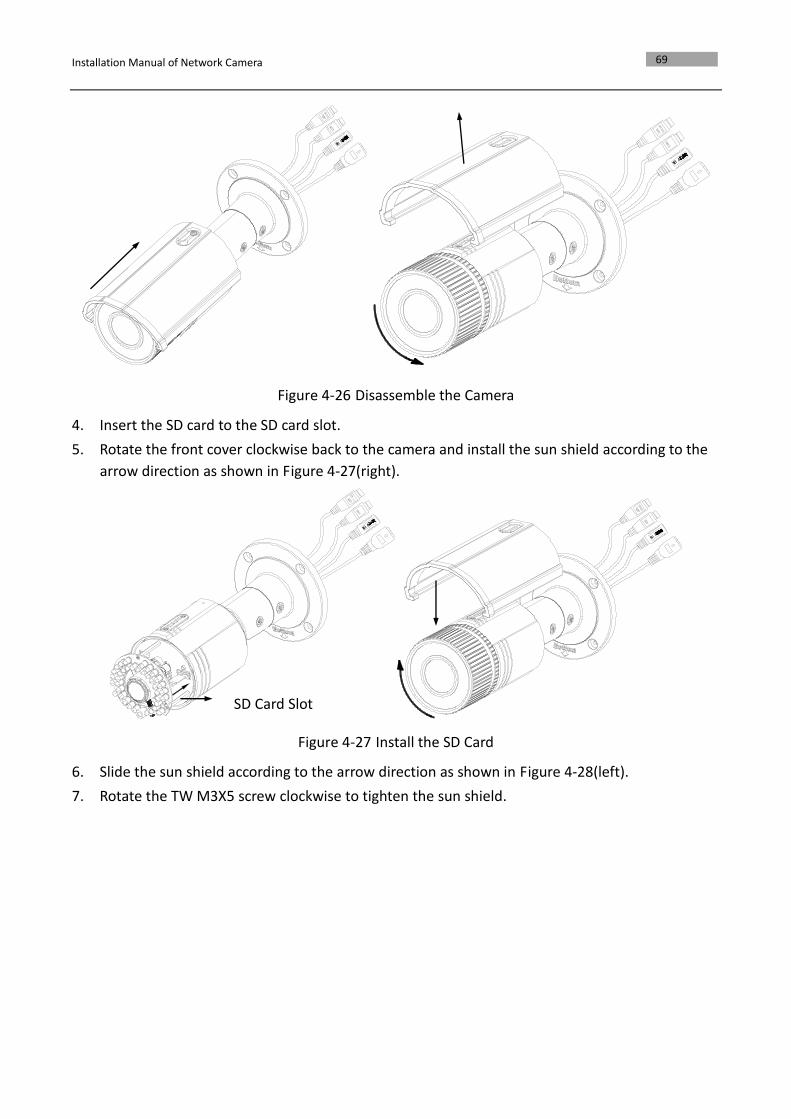
1. Rotate the TW M3X5 screw counterclockwise about 3 to 4 rounds to loosen it. Slide the sun
shield according to the arrow direction as shown in Figure 4-26(left).
2. Remove the sun shield according to the arrow direction as shown in Figure 4-26(right).
3. Remove the front cover by rotating it counterclockwise as shown in Figure 4-26(right).
Audio
Alarm
Installation Manual of Network Camera
69
Figure 4-26 Disassemble the Camera
4. Insert the SD card to the SD card slot.
5. Rotate the front cover clockwise back to the camera and install the sun shield according to the
arrow direction as shown in Figure 4-27(right).
Figure 4-27 Install the SD Card
6. Slide the sun shield according to the arrow direction as shown in Figure 4-28(left).
7. Rotate the TW M3X5 screw clockwise to tighten the sun shield.
SD Card Slot
Installation Manual of Network Camera
70
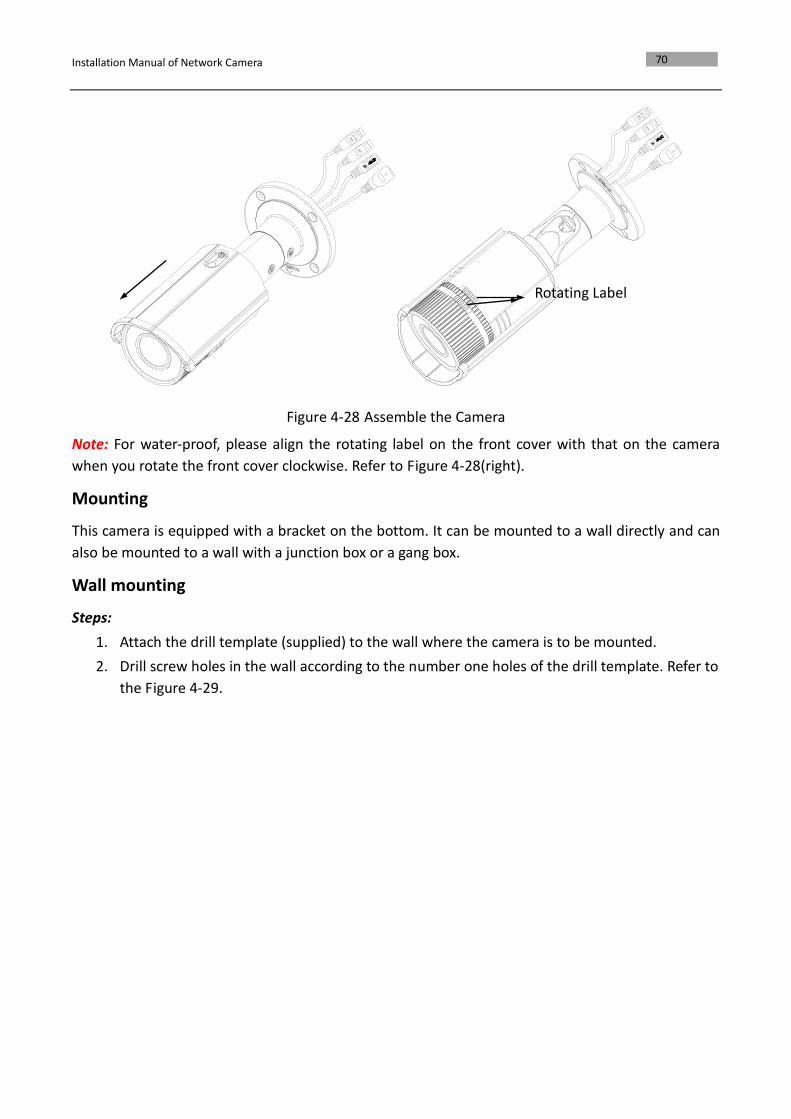
Figure 4-28 Assemble the Camera
Note: For water-proof, please align the rotating label on the front cover with that on the camera
when you rotate the front cover clockwise. Refer to Figure 4-28(right).
Mounting
This camera is equipped with a bracket on the bottom. It can be mounted to a wall directly and can
also be mounted to a wall with a junction box or a gang box.
Wall mounting
Steps:
1. Attach the drill template (supplied) to the wall where the camera is to be mounted.
2. Drill screw holes in the wall according to the number one holes of the drill template. Refer to
the Figure 4-29.
Rotating Label
Installation Manual of Network Camera
71
1 1
1 1
2
2 2
2
1:Screw Hole
for Bracket
2:Screw Hole
for Mounting Base
Cable Hole
Screw Hole
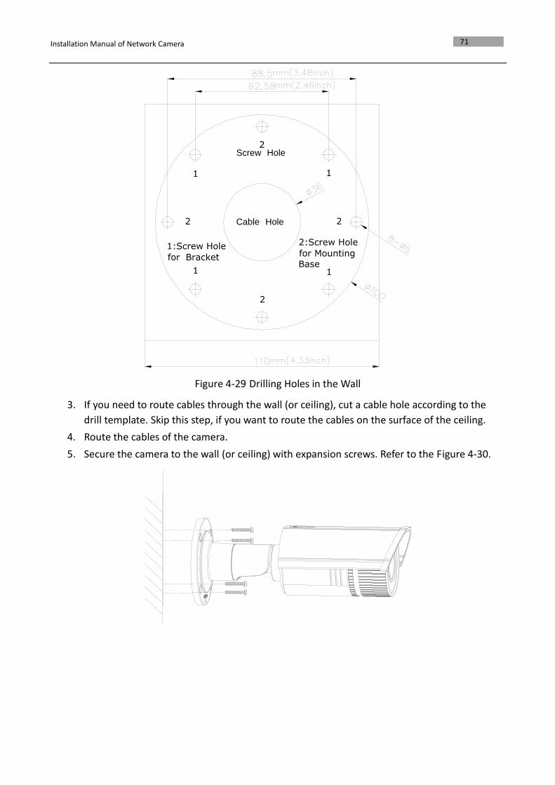
Figure 4-29 Drilling Holes in the Wall
3. If you need to route cables through the wall (or ceiling), cut a cable hole according to the
drill template. Skip this step, if you want to route the cables on the surface of the ceiling.
4. Route the cables of the camera.
5. Secure the camera to the wall (or ceiling) with expansion screws. Refer to the Figure 4-30.
Installation Manual of Network Camera
72
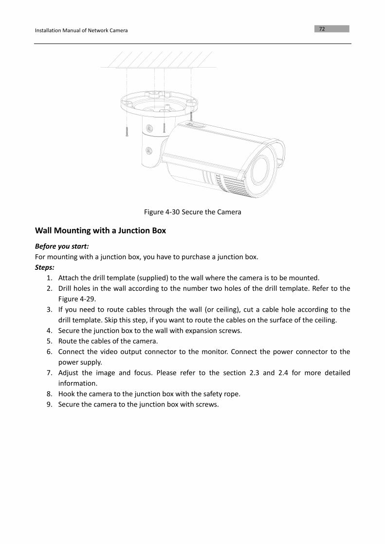
Figure 4-30 Secure the Camera
Wall Mounting with a Junction Box
Before you start:
For mounting with a junction box, you have to purchase a junction box.
Steps:
1. Attach the drill template (supplied) to the wall where the camera is to be mounted.
2. Drill holes in the wall according to the number two holes of the drill template. Refer to the
Figure 4-29.
3. If you need to route cables through the wall (or ceiling), cut a cable hole according to the
drill template. Skip this step, if you want to route the cables on the surface of the ceiling.
4. Secure the junction box to the wall with expansion screws.
5. Route the cables of the camera.
6. Connect the video output connector to the monitor. Connect the power connector to the
power supply.
7. Adjust the image and focus. Please refer to the section 2.3 and 2.4 for more detailed
information.
8. Hook the camera to the junction box with the safety rope.
9. Secure the camera to the junction box with screws.
Installation Manual of Network Camera
73
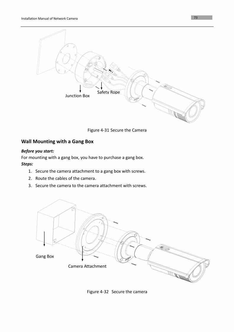
Figure 4-31 Secure the Camera
Wall Mounting with a Gang Box
Before you start:
For mounting with a gang box, you have to purchase a gang box.
Steps:
1. Secure the camera attachment to a gang box with screws.
2. Route the cables of the camera.
3. Secure the camera to the camera attachment with screws.
Figure 4-32 Secure the camera
Junction Box
Safety Rope
Camera Attachment
Gang Box
Installation Manual of Network Camera
74
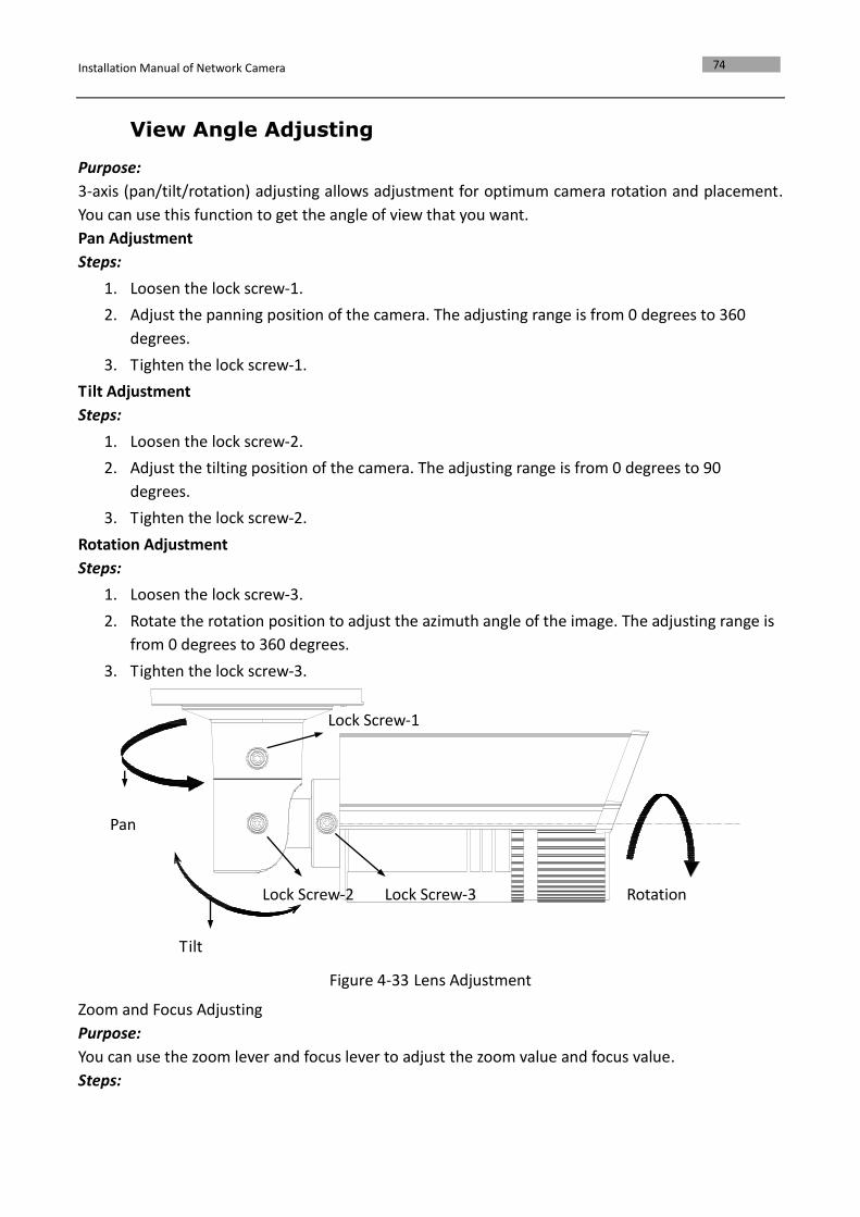
View Angle Adjusting
Purpose:
3-axis (pan/tilt/rotation) adjusting allows adjustment for optimum camera rotation and placement.
You can use this function to get the angle of view that you want.
Pan Adjustment
Steps:
1. Loosen the lock screw-1.
2. Adjust the panning position of the camera. The adjusting range is from 0 degrees to 360
degrees.
3. Tighten the lock screw-1.
Tilt Adjustment
Steps:
1. Loosen the lock screw-2.
2. Adjust the tilting position of the camera. The adjusting range is from 0 degrees to 90
degrees.
3. Tighten the lock screw-2.
Rotation Adjustment
Steps:
1. Loosen the lock screw-3.
2. Rotate the rotation position to adjust the azimuth angle of the image. The adjusting range is
from 0 degrees to 360 degrees.
3. Tighten the lock screw-3.
Figure 4-33 Lens Adjustment
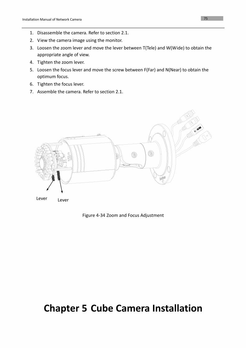
Zoom and Focus Adjusting
Purpose:
You can use the zoom lever and focus lever to adjust the zoom value and focus value.
Steps:
Pan
Tilt
Rotation
Lock Screw-1
Lock Screw-2
Lock Screw-3
Installation Manual of Network Camera
75
1. Disassemble the camera. Refer to section 2.1.
2. View the camera image using the monitor.
3. Loosen the zoom lever and move the lever between T(Tele) and W(Wide) to obtain the
appropriate angle of view.
4. Tighten the zoom lever.
5. Loosen the focus lever and move the screw between F(Far) and N(Near) to obtain the
optimum focus.
6. Tighten the focus lever.
7. Assemble the camera. Refer to section 2.1.
Figure 4-34 Zoom and Focus Adjustment
Chapter 5 Cube Camera Installation
Lever
Lever
Installation Manual of Network Camera
76
5.1 Cube Camera I
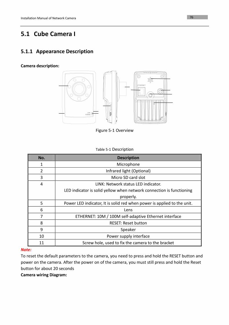
5.1.1 Appearance Description
Camera description:
Figure 5-1 Overview
Table 5-1 Description
No. Description
1 Microphone
2 Infrared light (Optional)
3 Micro SD card slot
4 LINK: Network status LED indicator.
LED indicator is solid yellow when network connection is functioning
properly.
5 Power LED indicator, It is solid red when power is applied to the unit.
6 Lens
7 ETHERNET: 10M / 100M self-adaptive Ethernet interface
8 RESET: Reset button
9 Speaker
10 Power supply interface
11 Screw hole, used to fix the camera to the bracket
Note:
To reset the default parameters to the camera, you need to press and hold the RESET button and
power on the camera. After the power on of the camera, you must still press and hold the Reset
button for about 20 seconds
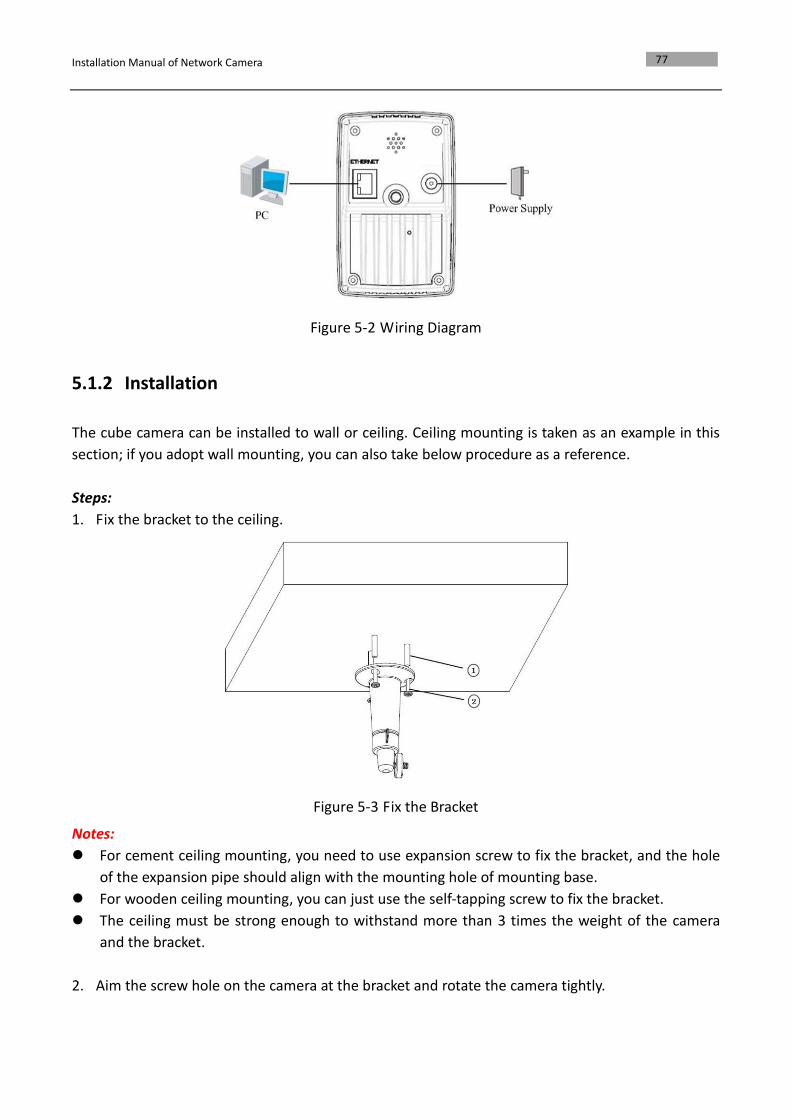
Camera wiring Diagram:
Installation Manual of Network Camera
77
Figure 5-2 Wiring Diagram
5.1.2 Installation
The cube camera can be installed to wall or ceiling. Ceiling mounting is taken as an example in this
section; if you adopt wall mounting, you can also take below procedure as a reference.
Steps:
1. Fix the bracket to the ceiling.
Figure 5-3 Fix the Bracket
Notes:
For cement ceiling mounting, you need to use expansion screw to fix the bracket, and the hole
of the expansion pipe should align with the mounting hole of mounting base.
For wooden ceiling mounting, you can just use the self-tapping screw to fix the bracket.
The ceiling must be strong enough to withstand more than 3 times the weight of the camera
and the bracket.
2. Aim the screw hole on the camera at the bracket and rotate the camera tightly.
Installation Manual of Network Camera
78
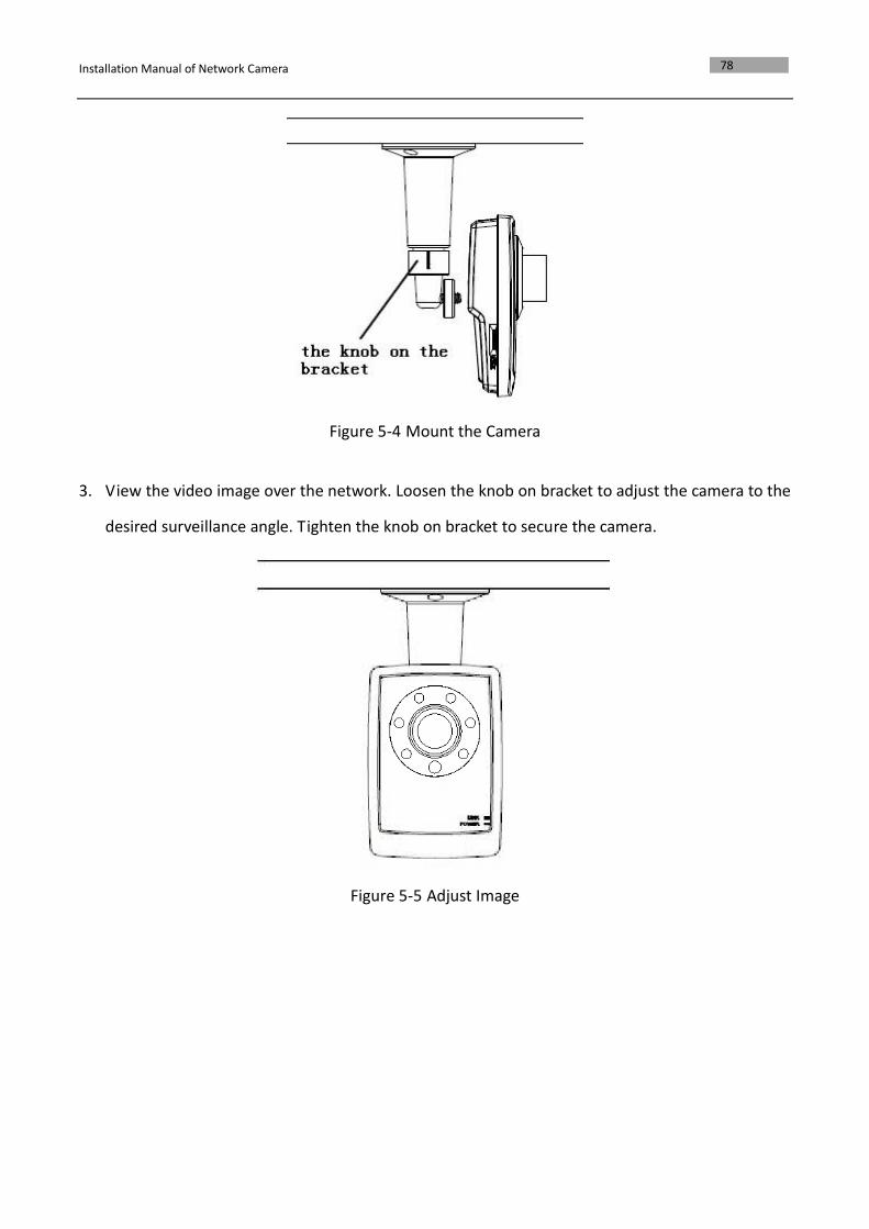
Figure 5-4 Mount the Camera
3. View the video image over the network. Loosen the knob on bracket to adjust the camera to the
desired surveillance angle. Tighten the knob on bracket to secure the camera.
Figure 5-5 Adjust Image
Installation Manual of Network Camera
79
5.2 Cube Camera II
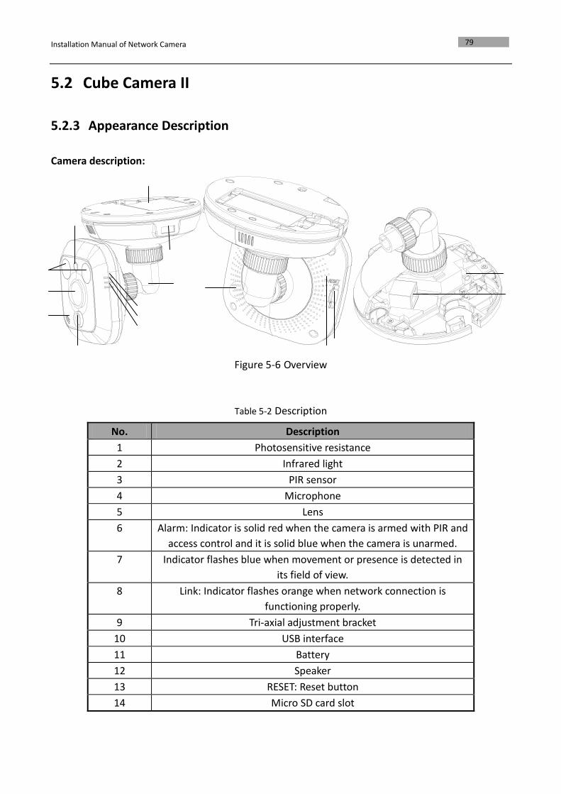
5.2.3 Appearance Description
Camera description:
Figure 5-6 Overview
Table 5-2 Description
No. Description
1 Photosensitive resistance
2 Infrared light
3 PIR sensor
4 Microphone
5 Lens
6 Alarm: Indicator is solid red when the camera is armed with PIR and
access control and it is solid blue when the camera is unarmed.
7 Indicator flashes blue when movement or presence is detected in
its field of view.
8 Link: Indicator flashes orange when network connection is
functioning properly.
9 Tri-axial adjustment bracket
10 USB interface
11 Battery
12 Speaker
13 RESET: Reset button
14 Micro SD card slot
Installation Manual of Network Camera
80
15 Power supply interface
16 10M / 100M self-adaptive Ethernet interface & PoE
Note:
To reset the default parameters to the camera, you need to press and hold the RESET button and
power on the camera. After the power on of the camera, you must still press and hold the Reset
button for about 20 seconds.
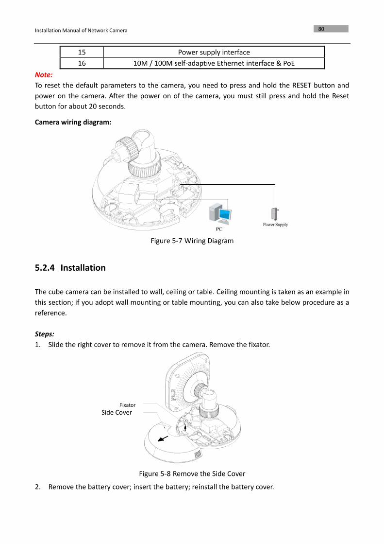
Camera wiring diagram:
Figure 5-7 Wiring Diagram
5.2.4 Installation
The cube camera can be installed to wall, ceiling or table. Ceiling mounting is taken as an example in
this section; if you adopt wall mounting or table mounting, you can also take below procedure as a
reference.
Steps:
1. Slide the right cover to remove it from the camera. Remove the fixator.
Figure 5-8 Remove the Side Cover
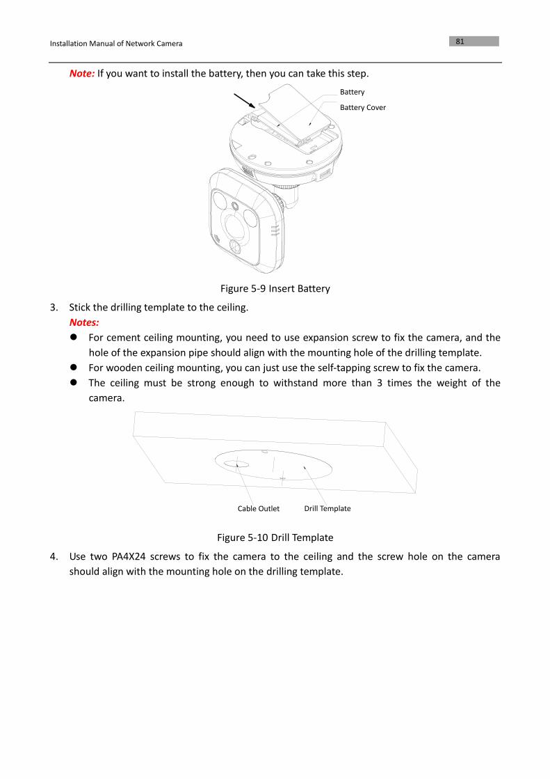
2. Remove the battery cover; insert the battery; reinstall the battery cover.
Fixator
Side Cover
Installation Manual of Network Camera
81
Note: If you want to install the battery, then you can take this step.
Figure 5-9 Insert Battery
3. Stick the drilling template to the ceiling.
Notes:
For cement ceiling mounting, you need to use expansion screw to fix the camera, and the
hole of the expansion pipe should align with the mounting hole of the drilling template.
For wooden ceiling mounting, you can just use the self-tapping screw to fix the camera.
The ceiling must be strong enough to withstand more than 3 times the weight of the
camera.
Figure 5-10 Drill Template
4. Use two PA4X24 screws to fix the camera to the ceiling and the screw hole on the camera
should align with the mounting hole on the drilling template.
Battery
Battery Cover
Cable Outlet Drill Template
Installation Manual of Network Camera
82
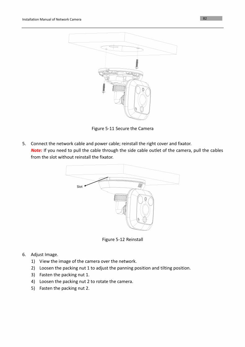
Figure 5-11 Secure the Camera
5. Connect the network cable and power cable; reinstall the right cover and fixator.
Note: If you need to pull the cable through the side cable outlet of the camera, pull the cables
from the slot without reinstall the fixator.
Figure 5-12 Reinstall
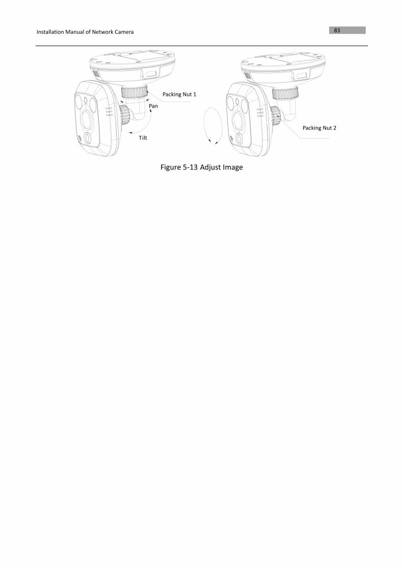
6. Adjust Image.
1) View the image of the camera over the network.
2) Loosen the packing nut 1 to adjust the panning position and tilting position.
3) Fasten the packing nut 1.
4) Loosen the packing nut 2 to rotate the camera.
5) Fasten the packing nut 2.
Slot
Installation Manual of Network Camera
83
Figure 5-13 Adjust Image
Packing Nut 2
Packing Nut 1
Tilt
Pan
Installation Manual of Network Camera
84
Chapter 6 Mini Dome Camera Installation
6.1 Appearance Description
Camera description:
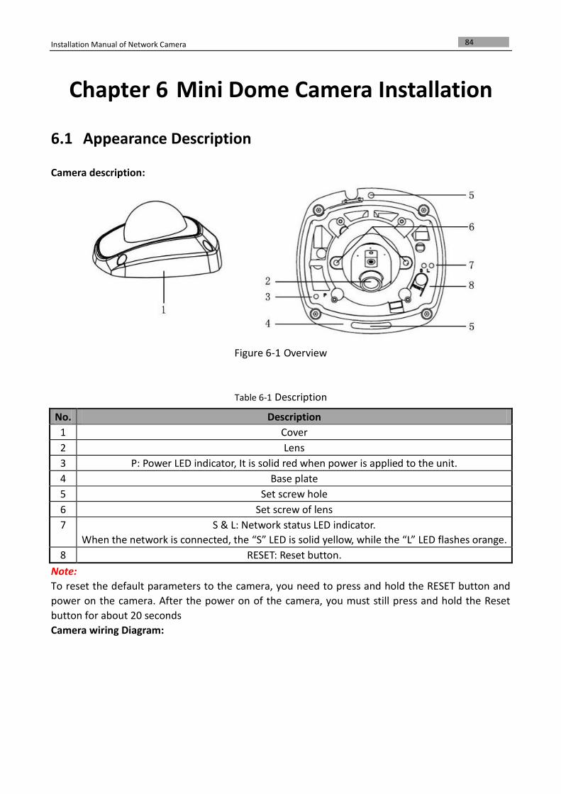
Figure 6-1 Overview
Table 6-1 Description
No. Description
1 Cover
2 Lens
3 P: Power LED indicator, It is solid red when power is applied to the unit.
4 Base plate
5 Set screw hole
6 Set screw of lens
7 S & L: Network status LED indicator.
When the network is connected, the “S” LED is solid yellow, while the “L” LED flashes orange.
8 RESET: Reset button.
Note:
To reset the default parameters to the camera, you need to press and hold the RESET button and
power on the camera. After the power on of the camera, you must still press and hold the Reset
button for about 20 seconds
Camera wiring Diagram:
Installation Manual of Network Camera
85
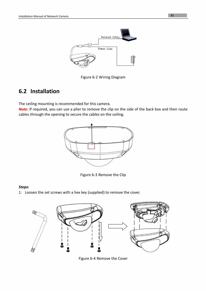
Figure 6-2 Wiring Diagram
6.2 Installation
The ceiling mounting is recommended for this camera.
Note: If required, you can use a plier to remove the clip on the side of the back box and then route cables through the opening to secure the cables on the ceiling.
Figure 6-3 Remove the Clip
Steps:
1. Loosen the set screws with a hex key (supplied) to remove the cover.
Figure 6-4 Remove the Cover
Installation Manual of Network Camera
86
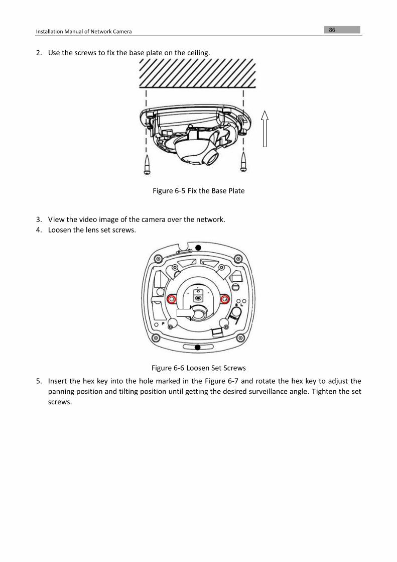
2. Use the screws to fix the base plate on the ceiling.
Figure 6-5 Fix the Base Plate
3. View the video image of the camera over the network.
4. Loosen the lens set screws.
Figure 6-6 Loosen Set Screws
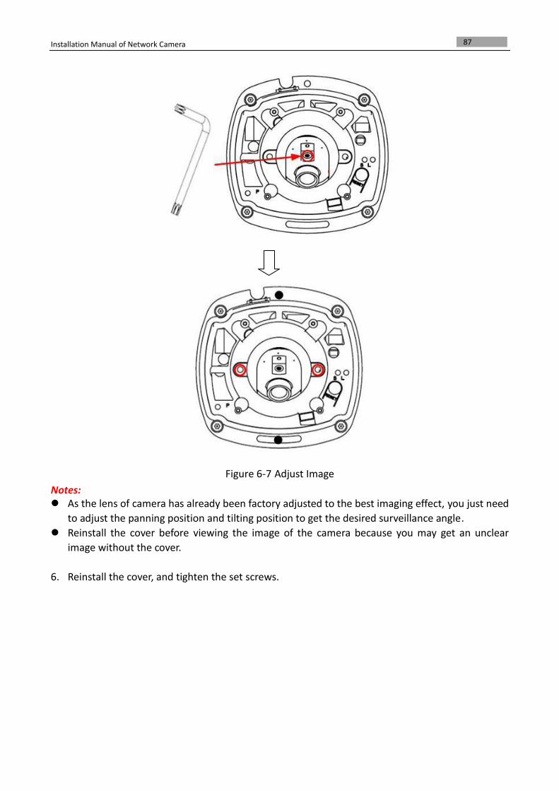
5. Insert the hex key into the hole marked in the Figure 6-7 and rotate the hex key to adjust the
panning position and tilting position until getting the desired surveillance angle. Tighten the set
screws.
Installation Manual of Network Camera
87
Figure 6-7 Adjust Image
Notes: As the lens of camera has already been factory adjusted to the best imaging effect, you just need
to adjust the panning position and tilting position to get the desired surveillance angle.
Reinstall the cover before viewing the image of the camera because you may get an unclear
image without the cover.
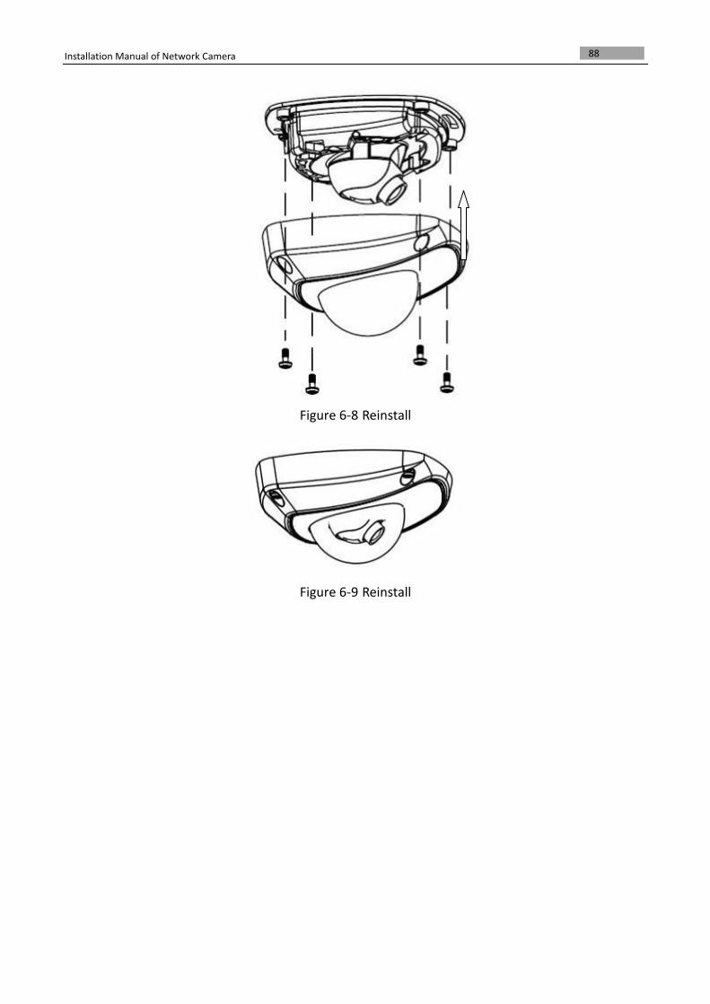
6. Reinstall the cover, and tighten the set screws.
Installation Manual of Network Camera
88
Figure 6-8 Reinstall
Figure 6-9 Reinstall