Embed Size (px)
Citation preview
NEURO-FUZZY BASED POWER SYSTEM STABILIZER OF A
MULTI-MACHINE SYSTEM
SYAMZURINA BINTI MD HASNAN
A project report submitted in partial fulfilment of the
requirements for the award of the degree of
Master of Engineering (Electrical-Power)
Faculty of Electrical Engineering
Universiti Teknologi Malaysia
NOVEMBER 2009
iii
Specially dedicated to my beloved parents
for their endless support and encouragements.

iv
ACKNOWLEDGEMENT
I wish to express my sincere appreciation to my project supervisor, P.M. Md
Shah Bin Majid for all his guidance, encouragement and support in completing the
master project.
Most importantly, I would like to extend my gratitude to my parents for their
support and patience during my pursuit for higher studies. They have encouraged me
throughout my education, and I will always be grateful for their sacrifice, generosity
and love.
Finally yet importantly, thanks to all the persons who directly or indirectly
contributed because their perspective and guidance helped greatly to point me in the
right direction until the completion of this thesis.
v
ABSTRACT
This thesis presents a study of neuro-fuzzy power system stabilizer (PSS) for
stability enhancement of a multi-machine power system. In order to accomplish a
stability enhancement, speed deviation (∆ω) and acceleration (∆ ) of the rotor
synchronous generator were taken as the input to the neuro-fuzzy controller. These
variables take significant effects on damping the generator shaft mechanical
oscillations. The stabilizing signals were computed using the neuro-fuzzy
membership function depending on these variables. Simulink Block Design and
Matlab 7.6 were utilized in implementing the study. The simulations were tested
under different types of conditions; the steady state operation, the three phases to
ground fault, with load connected to the system, mechanical input power changes
and reference voltage (Vref) step changes. The performance of the neuro-fuzzy power
system stabilizer was compared with the conventional power system stabilizer and
without power system stabilizer.
vi
ABSTRAK Tesis ini membentangkan kajian Penstabil Sistem Kuasa neuro-fuzzy untuk
meningkatkan tahap kestabilan suatu sistem penjana segerak. Untuk meningkatkan
tahap kestabilan sistem ini, perbezaan kelajuan (∆ω) dan pecutan (∆ ) rotor pada
penjana segerak digunakan sebagai isyarat masukan pengawal neuro-fuzzy. Isyarat
masukan ini memberi kesan secara langsung bagi mengurangkan ayunan mekanikal
terhadap aci penjana. Isyarat ini ditukarkan ke bentuk fungsi keanggotaan
berdasarkan kelakuan penjana tersebut. Semua model dan analisis menggunakan
perisian Simulink (MATLAB 7.6). Simulasi dijalankan berdasarkan beberapa
keadaan iaitu keadaan mantap, kerosakan tiga fasa ke bumi, penjana berbeban,
perubahan kuasa masukan mekanikal dan perubahan voltan rujukan (Vref).
Perbandingan dilakukan antara Penstabil Sistem Kuasa neuro-fuzzy dengan Penstabil
Sistem Kuasa Konvensional dan sistem tanpa Penstabil Sistem Kuasa untuk mencari
teknik kawalan yang terbaik.
vii
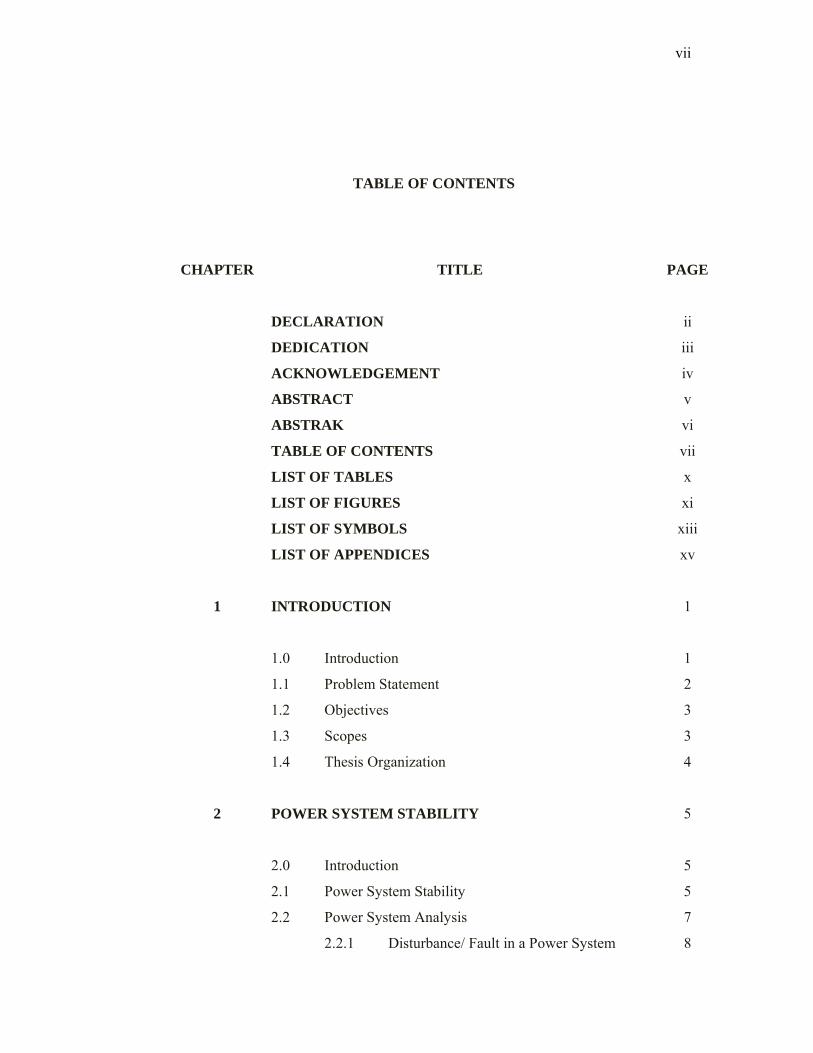
TABLE OF CONTENTS
CHAPTER TITLE PAGE
DECLARATION ii
DEDICATION iii
ACKNOWLEDGEMENT iv
ABSTRACT v
ABSTRAK vi
TABLE OF CONTENTS vii
LIST OF TABLES x
LIST OF FIGURES xi
LIST OF SYMBOLS xiii
LIST OF APPENDICES xv
1 INTRODUCTION 1
1.0 Introduction 1
1.1 Problem Statement 2
1.2 Objectives 3
1.3 Scopes 3
1.4 Thesis Organization 4
2 POWER SYSTEM STABILITY 5
2.0 Introduction 5
2.1 Power System Stability 5
2.2 Power System Analysis 7
2.2.1 Disturbance/ Fault in a Power System 8
viii
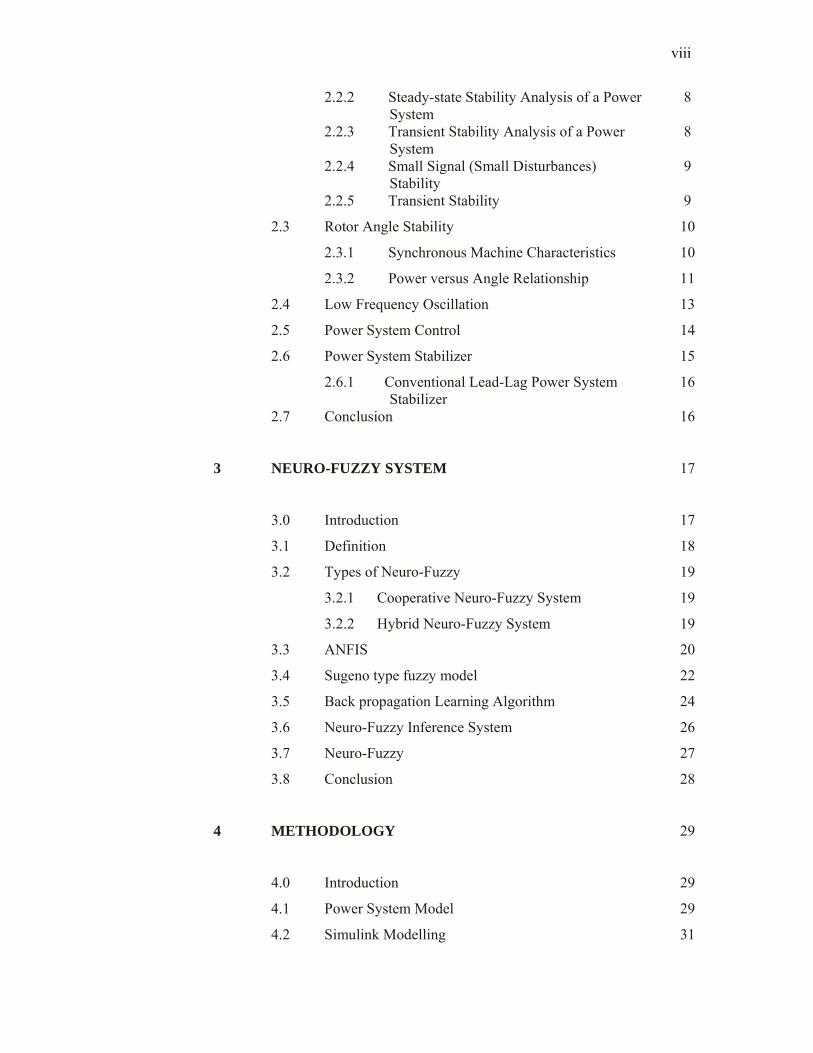
2.2.2 Steady-state Stability Analysis of a Power System
8
2.2.3 Transient Stability Analysis of a Power System
8
2.2.4 Small Signal (Small Disturbances) Stability
9
2.2.5 Transient Stability 9
2.3 Rotor Angle Stability 10
2.3.1 Synchronous Machine Characteristics 10
2.3.2 Power versus Angle Relationship 11
2.4 Low Frequency Oscillation 13
2.5 Power System Control 14
2.6 Power System Stabilizer 15
2.6.1 Conventional Lead-Lag Power System Stabilizer
16
2.7 Conclusion 16
3 NEURO-FUZZY SYSTEM 17
3.0 Introduction 17
3.1 Definition 18
3.2 Types of Neuro-Fuzzy 19
3.2.1 Cooperative Neuro-Fuzzy System 19
3.2.2 Hybrid Neuro-Fuzzy System 19
3.3 ANFIS 20
3.4 Sugeno type fuzzy model 22
3.5 Back propagation Learning Algorithm 24
3.6 Neuro-Fuzzy Inference System 26
3.7 Neuro-Fuzzy 27
3.8 Conclusion 28
4 METHODOLOGY 29
4.0 Introduction 29
4.1 Power System Model 29
4.2 Simulink Modelling 31
ix
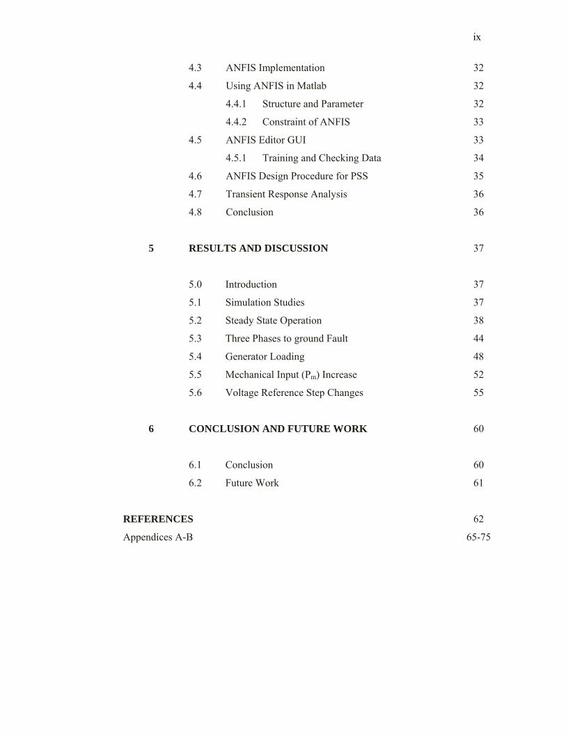
4.3 ANFIS Implementation 32
4.4 Using ANFIS in Matlab 32
4.4.1 Structure and Parameter 32
4.4.2 Constraint of ANFIS 33
4.5 ANFIS Editor GUI 33
4.5.1 Training and Checking Data 34
4.6 ANFIS Design Procedure for PSS 35
4.7 Transient Response Analysis 36
4.8 Conclusion 36
5 RESULTS AND DISCUSSION 37
5.0 Introduction 37
5.1 Simulation Studies 37
5.2 Steady State Operation 38
5.3 Three Phases to ground Fault 44
5.4 Generator Loading 48
5.5 Mechanical Input (Pm) Increase 52
5.6 Voltage Reference Step Changes 55
6 CONCLUSION AND FUTURE WORK 60
6.1 Conclusion
6.2 Future Work
60
61
REFERENCES 62
Appendices A-B 65-75
x
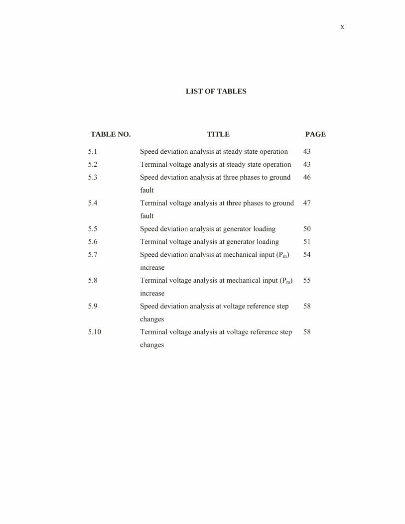
LIST OF TABLES
TABLE NO. TITLE PAGE
5.1 Speed deviation analysis at steady state operation 43
5.2 Terminal voltage analysis at steady state operation 43
5.3 Speed deviation analysis at three phases to ground
fault
46
5.4 Terminal voltage analysis at three phases to ground
fault
47
5.5 Speed deviation analysis at generator loading 50
5.6 Terminal voltage analysis at generator loading 51
5.7 Speed deviation analysis at mechanical input (Pm)
increase
54
5.8 Terminal voltage analysis at mechanical input (Pm)
increase
55
5.9 Speed deviation analysis at voltage reference step
changes
58
5.10 Terminal voltage analysis at voltage reference step
changes
58
xi
LIST OF FIGURES
FIGURE NO. TITLE PAGE
2.1 The Power System Analysis 7
2.2 Power Transfer Characteristic of a two machine
system
13
2.3 Diagram of a synchronous generator excitation
control system
15
2.4 Block diagram of a typical Power System Stabilizer 16
3.1 A Hybrid Neuro-Fuzzy Controller 20
3.2 Structure of ANFIS 23
3.3 Structure of Neuro-Fuzzy Inference System 26
4.1 Power System Model 30
4.2 Simulink block diagram for neuro-fuzzy PSS 31
4.3 Checking data 34
4.4 Flow Chart of ANFIS Procedure 35
5.1 Subsystem for Machine 1 38
5.2 Subsystem for Machine 2 39
5.3 Subsystem for Area 1 with Machine 1 and 2 39
5.4 Subsystem for Area 2 with Machine 3 and 4 40
5.5 Two area, 4 machines and 11 bus system for Steady
State Operation
40
5.6 Speed deviation and terminal voltage response for
steady state operation
41
5.7 Two area, 4 machines and 11 bus system for Three
Phases to ground Fault
44
5.8 Speed deviation and terminal voltage response for
three phases to ground fault
46
xii
5.9 Two area, 4 machines and 11 bus system for
Generator Loading
48
5.10 Speed deviation and terminal voltage response for
generator loading
50
5.11 At area 1, Mechanical Input (Pm) Increase for
Machine 1
52
5.12 Speed deviation and terminal voltage response for
mechanical input (Pm) increase
53
5.13 At area 1, Voltage Reference Step Changes for
Machine 1
55
5.14 Speed deviation and terminal voltage response for
voltage reference step changes
57
xiii
LIST OF SYMBOLS
PSS - Power System Stabilizer
CPSS - Conventional Power System Stabilizer
ANFIS - Adaptive Neuro-Fuzzy Inference System
FIS - Fuzzy Inference System
MSE - Means Square Error
SSE - Sum of Square Error
J - Total moment of inertia of the rotor masses in kgm2
θm - Angular displacement of the rotor with respect to a
stationary axis in mechanical radians (rad)
Pe - Electrical power
Pm - Mechanical power
Ta - Net accelerating torque in Nm
Tm - Mechanical or shaft torque supplied by the prime mover
less retarding torque due to rotational losses in Nm
Te - Net accelerating and electromagnetic torque in Nm
M - Inertia constant of machine (MJ/rad)
δ - Rotor angle perturbation
P - Active power (W)
ω - Rotor speed of synchronous machine (rad/s)
∆ω - Rotor speed deviation (rad/s)
TS - Synchronizing torque coefficient
TD - Damping torque coefficient
∆δ - Delta rotor angle
∆VT - Delta terminal voltage
f - Output frequency
N - Rotor speed in rpm
P - Number of poles
xiv
PREF - Mechanical power references
PSV - Feedback through governor
TM - Turbine output torque
Vinf - Infinite bus voltage
VTREF - Terminal voltage reference
VT - Terminal voltage
VA - Voltage regulator output
VF - Field voltage
VE - Excitation system stabilizing signal
∆ω - Speed deviation
∆ - Acceleration
VPSS - PSS output signal
Q - Reactive power (VAR)
µ - Membership function
ci - The center of membership function
σi - The widths of membership function
xv
LIST OF APPENDICES
APPENDIX TITLE PAGE
A Power System Model Parameter 65
A1 Synchronous Generator 65
A2 Excitation System 66
A3 Hydraulic Turbine and Generator 67
A4 Conventional Power System Stabilizer 68
A5 Transmission Line 69
A6 Three Phase Fault 70
B ANFIS Toolbox 71
B1 Training Data 71
B2 Data for training, checking and testing 72
B3 Generate FIS 72
B4 Feedforward Neural Network Architecture 73
B5 Training Error 73
B6 Multi Input Single Output 74
B7 5 membership function 74
B8 Rule Editor 75
1
CHAPTER 1
INTRODUCTION 1.0 Introduction
An interconnected power system basically consists of several essential
components. They are namely the generating units, the transmission lines, the loads,
the transformer, static VAR compensators and lastly HVDC lines [1]. During the
operation of the generators, there may be some disturbances such as sustained
oscillations in the speed or periodic variations in the torque that is applied to the
generator. These disturbances may result in voltage or frequency fluctuation that may
affect the other parts of the interconnected power system [1].
External factors, such as lightning, can also cause disturbances to the power
system. All these disturbances are termed as faults. When a fault occurs, it causes the
motor to lose synchronism if the natural frequency of oscillation coincides with the
frequency of oscillation on the generators. With these factors in mind, the basic
condition for a power system with stability is synchronism. Besides this condition,
there are other important condition such as steady-state stability, transient stability,
harmonics and disturbance, collapse of voltage and the loss of reactive power [2].
The stability of a system is defined as the tendency and ability of the power
system to develop restoring forces equal to or greater than the disturbing forces to
maintain the state of equilibrium [1].the system is also considered as a stable if it
converges to another equilibrium position in the proximity of initial equilibrium
point. If the physical state of the system differs such that certain physical variable
increases with respect to time, the system is considered to be unstable. Therefore, the
2
system is said to remain stable when the forces tending to hold the machines in
synchronism with one another are enough to overcome the disturbances [2]. The
system stability that is of most concern is the characteristic and the behaviours of the
power system after a disturbance.
Stability studies are generally categorized into two major areas: steady-state
stability and transient stability [1]. Steady-state stability is the ability of the power
system to regain synchronism after encountering small and slow disturbances.
Example of small and slow disturbances is gradual power changes. Dynamic stability
is the ability to regain synchronism after encountering small disturbances within a
long time frame. The effects of large and sudden disturbances are known as transient
stability. Examples of such faults are sudden outrage of a transmission line or the
sudden addition of removal of the loads. The transient stability occurs when the
power system is able to withstand the transient conditions following a major
disturbance [2].
Power system stabilizers are used to generate supplementary control signals
for the excitation system in order to damp the low frequency inter-area and intra-area
oscillations [3]. The most widely used in existing power system is conventional
power system stabilizer and has made a contribution in enhancing power system
dynamic stability.
A supplementary excitation controllers referred to as power system stabilizer
(PSS) have been added to synchronous generators to counteract the effect of high
gain automatic voltage regulator (AVR) and other sources of negative damping [4].
The stabilizer should produce a component of electrical torque in order to provide a
damping on the rotor which is in phase with speed variations.
1.1 Problem Statement Power systems are complex nonlinear systems and often result in low-
frequency power oscillations due to insufficient damping. Unfortunately, AVR
provide negative damping that can make the system unstable, especially in large
3
system. Power system stabilizers provide this supplementary stabilizing signal and
are widely used to suppress the generator electromechanical oscillations and enhance
the overall stability of power systems [5].
Conventional PSS are based on linearized machine model and thus tuned at a
certain operating point. Since, power systems are highly nonlinear complex systems,
with configurations and parameters that change time, the conventional PSS design
cannot guarantee its performance in a practical operating environment [5].
1.2 Objectives The objectives of the project are:
i. To simulate and design a power system stabilizer (PSS) based on neuro-
fuzzy
ii. To examine/ analyse the effect of a fault in a multi-machine power
systems with PSS using MATLAB
iii. To make a performance comparison between without PSS, conventional
PSS and with the neuro-fuzzy PSS
1.3 Scopes The scope of this project will be undertaken in the following five
development stages which are:
i. Study the power system stability phenomenon for multi-machine
synchronous generator and control system using fuzzy logic and neural
network techniques.
ii. Design a power system stabilizer based on neuro-fuzzy in MATLAB.
iii. Simulate the controller design in MATLAB power system toolbox and
compare both controllers performance in an interconnected power system.
4
1.4 Thesis Organization The rest of the thesis is organized as follow:
Chapter 2 describes the power system stability phenomena and power
system stabilizers are used on generator. This chapter also discusses the basic theory
of synchronous generator such as the model and related equations of the relationship
between generator and load.
Chapter 3 discusses the basic of intelligent control techniques by neuro-
fuzzy and some approaches of neuro-fuzzy system also will be explained. This
chapter also briefly explains the structure and type of model used in neuro-fuzzy
controller.
Chapter 4 discusses the parameter of power system modelling and proposed
neuro-fuzzy PSS design. The power system modelling is illustrated by Simulink
block diagram which presents highly interactive surroundings for simulation.
Chapter 5 presents the simulation results of the neuro-fuzzy design and
discussion on the result from simulation using MATLAB. The structures of neuro-
fuzzy are tested in several disturbances such as a three phases to ground fault,
generator loading, mechanical input (Pm) increase and voltage reference step changes
in interconnected power system. The dynamic responses of synchronous machine
during test conditions are performed and performances between without neuro-fuzzy
and with neuro-fuzzy are discussed.
Chapter 6 gives the conclusion for the thesis and provide relevant
recommendation to improve the stability and negative damping which include further
research in this work.
62
REFERENCES
[1] H. Saadat, Power System Analysis: McGraw-Hill International Edition,
(1999).
[2] L. Z. Racz and B. Bokay, Power System Stability Amsterdam; New York:
Elsevier, (1988).
[3] Larsen, E.V. and Swann, D.A., “Applying power system stabilizers, Part I, II,
III”, IEEE Transaction on Power Apparatus and Systems, PAS-100 No. 6: Pp.
3017-3041, 1981.
[4] Othman Bin Jais, “Study of Fuzzy Logic Power System Stabilizer”, Thesis
UTM, (2002).
[5] Ruhua You, Hassan J. Eghbali, and M. Hashem Nehrir, “An Online Adaptive
Power system Stabilizer for Multimachine Systems”, IEEE Trans. On Power
System, Vol 18, No 1: Pp 128-135, 2003.
[6] Kundur, P., Power System Stability and Control. United States of America:
McGraw-Hill, (1994).
[7] Grainger, J.J., and Stevenson, W.D., Power System Analysis. New York:
McGraw-Hill, (1994).
[8] Claudio A. Canizares and Fernaado L. Alvarado, “Point of Collapse and
Continuous Methods for large AC/DC system”, IEEE Transaction on Power
System, Volume 7, No 1: Pp 1-8, February 1993.
63
[9] Yi Guo, David J. Hill and Youyi Wang, “Nonlinear decentralized control of
largescale power systems”, Automatica, Pp 1275-1289, 2000.
[10] Juang, C.F.A. “TSK-Type Recurrent Fuzzy Network for Dynamics Systems
Processing by Neural Network and Genethic Algorithms”,. IEEE Transaction
on Fuzzy System, Vol 10, No 2: Pp 155-170, 2002.
[11] Aaron Francis Snyder, “Inter-Area Oscillation Damping with Power System
Stabilizer and Synchronized Phasor Measurement”, Thesis Faculty of the
Virgina Polytechnic Institute and State University, February 1997.
[12] N.L. Pahalawaththa, G.S. Hope and O.P. Malik, “An Implicit Self-Tuning
Regulator as A Power System Stabilizer”, IEEE Transactions on Energy: Pp.
103-106, 1986.
[13] Elly Yuza Mahmud, “Fault Detection in Power Transmission Line using
Neuro Fuzzy”, Thesis UTM, (2006).
[14] L.X. Wang and J.M. Mendel, “Fuzzy Basis Functions, Universal
Approximation, and Orthogonal Least-Squares Learning”, IEEE Trans. On
Neural Network, Vol 3, No 5: Pp 807-814, 1992.
[15] D. Nauck and R. Kruse, Designing Neuro Fuzzy Systems through
Backpropagation, Paradigms and Practice: Pp 203-228,Kluwer, Boston,
(1996).
[16] D. Nauck and R. Kruse, “Neuro-Fuzzy Classification with NEFCLASS”, in P.
Kleinschmidt, A. Bachem, U. Derigs, D. Fischer, U. Leopold-Wildburger and
R. Möhring (eds.), Operations Research Proceedings 1995: Pp. 294-299,
1996.
[17] J.S. Jang, “ANFIS: Adaptive-Network-Based Fuzzy Inference System”, IEEE
Trans on Systems, Man and Cybernetics, Vol 23, No 3: Pp 665-684, 1993.
64
[18] T. Takagi and M. Sugeno, “Fuzzy Identifiction of Systems and it’s
Applications to Modeling and Control”, IEEE Transaction on Systems, Man
and Cybernatics, Vol. 15: Pp116-132, 1983.
[19] Negnevitsky, M. Intelligent System and Soft Computing with Practical
Application using Matlab. University of Tasmania, Australia. Unpublished.
[20] Lin, C. T. ed. Neural Fuzzy Control System with Structure and Parameter
Learning. Singapore: World Scientific, (1994).
[21] W. Liu, G. K. V. Moorthy, and D. C.Wunsch, II, “Adaptive Neural Network
based Power System Stabilizer Design”, IEEE Trans on Power System, Vol
4, No 5: Pp 2970–2975, 2003.
[22] D. K. Chaturvedi and O. P. Malik, “Neurofuzzy Power System Stabilizer”, IEEE Transaction on Energy Conversion, Vol 23, No 3: Pp 887-894, 2008.
[23] Fuzzy Logic toolbox for use with MATLAB-user’s guide (version 2), The
Mathworks Inc., Natick, Massachusetts; 2000.