Embed Size (px)
DESCRIPTION
New high permeability materials for EMI suppression. [email protected] February 2011. Contents. High permeability materials evolution What is improved? What is new in 3E10 & 3E12? 3E10 3E12 Standard range in 3E10 &3E12 Applications. High permeability materials evolution. - PowerPoint PPT Presentation
Citation preview
2
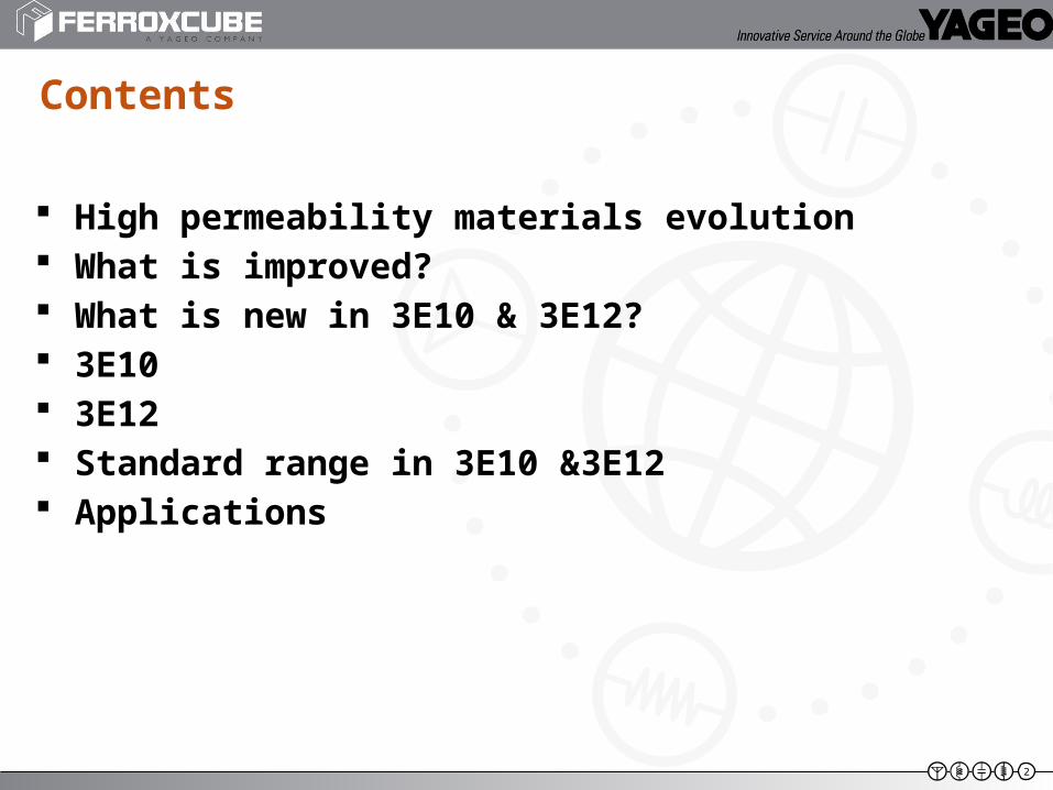
High permeability materials evolution What is improved? What is new in 3E10 & 3E12? 3E10 3E12 Standard range in 3E10 &3E12 Applications
Contents
3
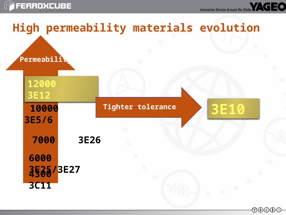
Permeability
High permeability materials evolution
7000 3E26
10000 3E5/6
4300 3C11
6000 3E25/3E27
3E10
12000 3E12
Tighter tolerance
4
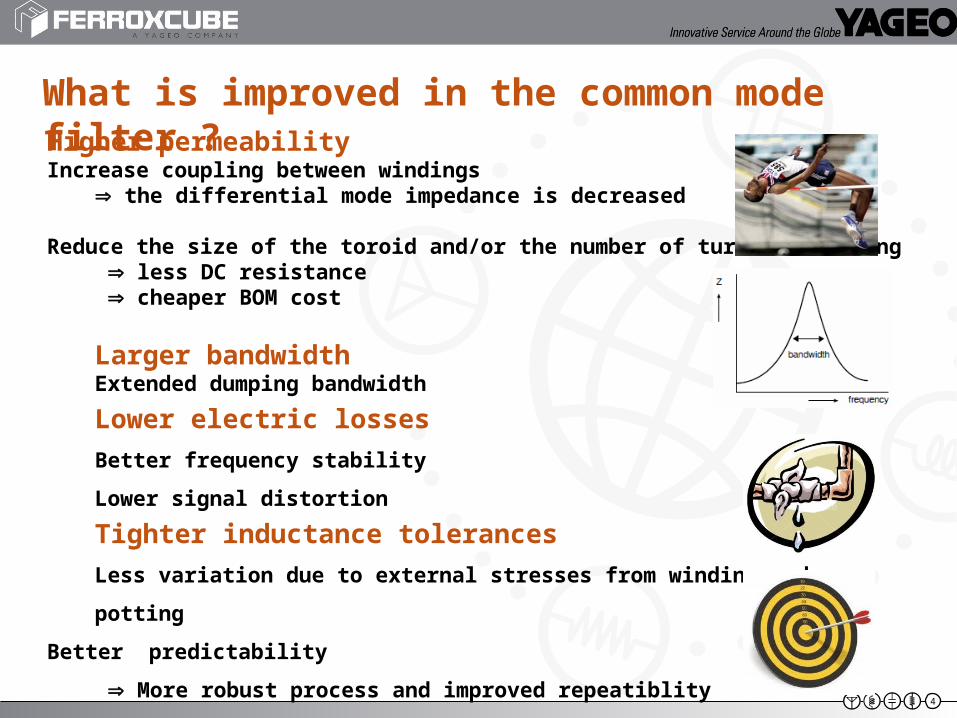
What is improved in the common mode filter ?Higher permeabilityIncrease coupling between windings
the differential mode impedance is decreased
Reduce the size of the toroid and/or the number of turns of winding less DC resistance cheaper BOM cost
Larger bandwidthExtended dumping bandwidth
Lower electric losses
Better frequency stability
Lower signal distortion
Tighter inductance tolerances
Less variation due to external stresses from winding and potting
Better predictability
More robust process and improved repeatiblity
5
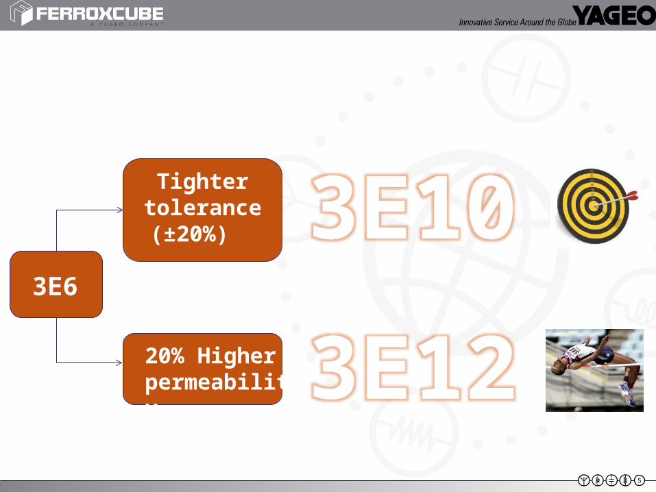
3E10
3E123E6
Tighter tolerance (±20%)
20% Higher permeability
6
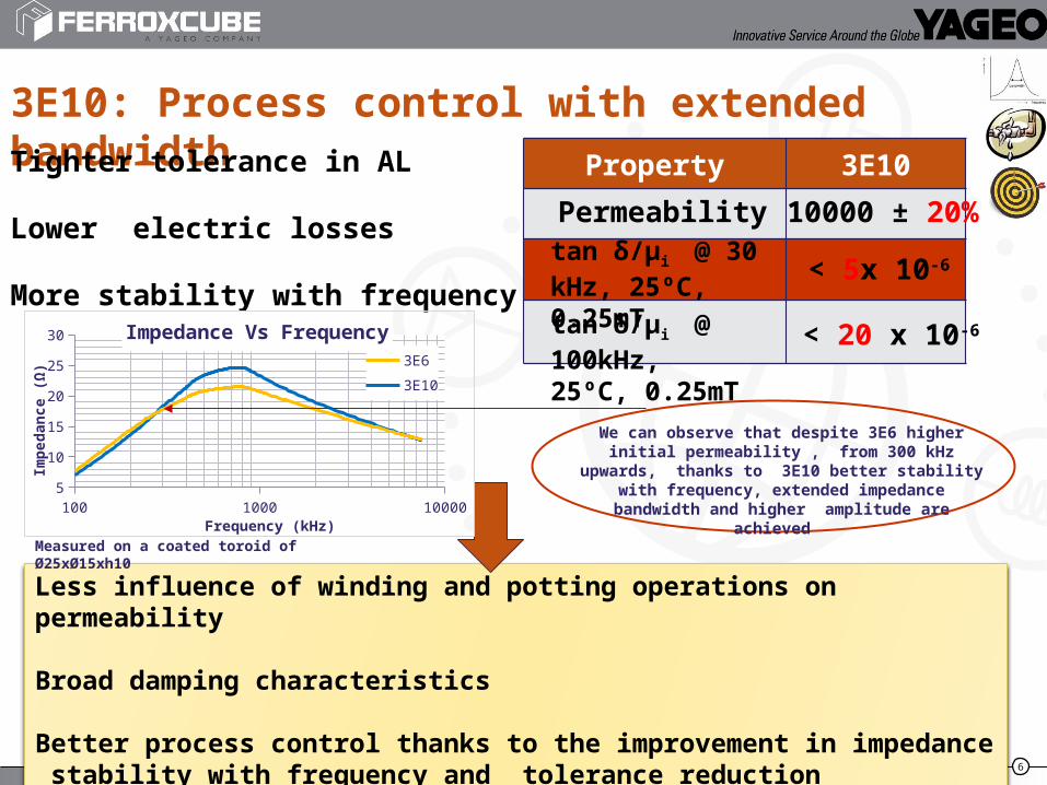
3E10: Process control with extended bandwidthProperty 3E10Tighter tolerance in AL
Lower electric losses
More stability with frequency
Less influence of winding and potting operations on permeability
Broad damping characteristics
Better process control thanks to the improvement in impedance stability with frequency and tolerance reduction
tan δ/μi @ 30 kHz, 25ºC, 0.25mT
< 5x 10⁻⁶
tan δ/μi @ 100kHz, 25ºC, 0.25mT
< 20 x 10-6
Permeability 10000 ± 20%
100 1000 100005
10
15
20
25
30 Impedance Vs Frequency
3E6
3E10
Frequency (kHz)
Imp
edan
ce (
Ω)
Measured on a coated toroid of Ø25xØ15xh10
We can observe that despite 3E6 higher initial permeability , from 300 kHz upwards, thanks to
3E10 better stability with frequency, extended impedance bandwidth and higher amplitude are
achieved
7
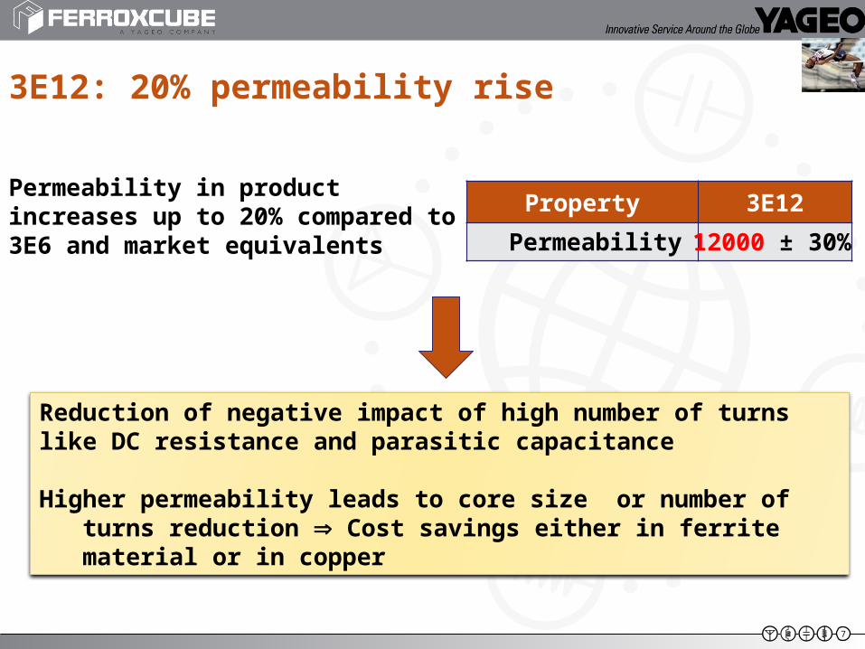
Permeability in product increases up to 20% compared to 3E6 and market equivalents
3E12: 20% permeability rise
Property 3E12
Reduction of negative impact of high number of turns like DC resistance and parasitic capacitance
Higher permeability leads to core size or number of turns reduction Cost savings either in ferrite material or in copper
Permeability 12000 ± 30%
8
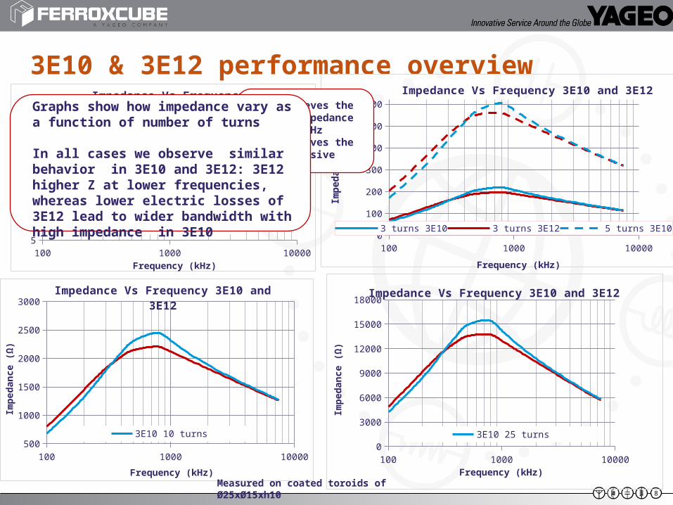
3E10 & 3E12 performance overview
100 1000 100005
10
15
20
25
30Impedance Vs Frequency
3E6 3E10 3E12
Frequency (kHz)
Imp
edan
ce (
Ω)
100 1000 100000
100
200
300
400
500
600
Impedance Vs Frequency 3E10 and 3E12
3 turns 3E10 3 turns 3E12 5 turns 3E10
Frequency (kHz)
Imp
ed
an
ce
(Ω
)
100 1000 10000500
1000
1500
2000
2500
3000Impedance Vs Frequency 3E10 and 3E12
3E10 10 turns 3E12 10 turns
Frequency (kHz)
Imp
edan
ce (
Ω)
100 1000 100000
3000
6000
9000
12000
15000
18000Impedance Vs Frequency 3E10 and 3E12
3E10 25 turns 3E12 25 turns
Frequency (kHz)
Imp
edan
ce (
Ω)
3E12 achieves the highest impedance up to 300kHz3E10 achieves the most extensive widthband
Graphs show how impedance vary as a function of number of turns
In all cases we observe similar behavior in 3E10 and 3E12: 3E12 higher Z at lower frequencies, whereas lower electric losses of 3E12 lead to wider bandwidth with high impedance in 3E10
Measured on coated toroids of Ø25xØ15xh10
9
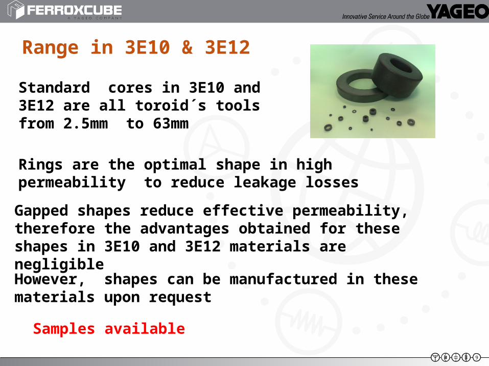
Range in 3E10 & 3E12
Standard cores in 3E10 and 3E12 are all toroid´s tools from 2.5mm to 63mm
Gapped shapes reduce effective permeability, therefore the advantages obtained for these shapes in 3E10 and 3E12 materials are negligible
However, shapes can be manufactured in these materials upon request
Rings are the optimal shape in high permeability to reduce leakage losses
Samples available
10
ApplicationsThe main applications are interference suppression and wideband transformers:
Wideband transformers Impedance transformation over a broad frequency range. Applications include impedance matching, voltage or current transformation, DC isolation, balanced/unbalanced mixing, power splitting, coupling, and signal inversion. Telecommunications devices
Pulse transformers Communication systems and digital networks
Ground fault interruptors (GFI) Home and industrial
Interference suppression Common mode choke. Mains filters in all type of electronic equipment.
ATTENTION TO HIGH GROWTH INVERTERS MARKET!!!!!!!
11
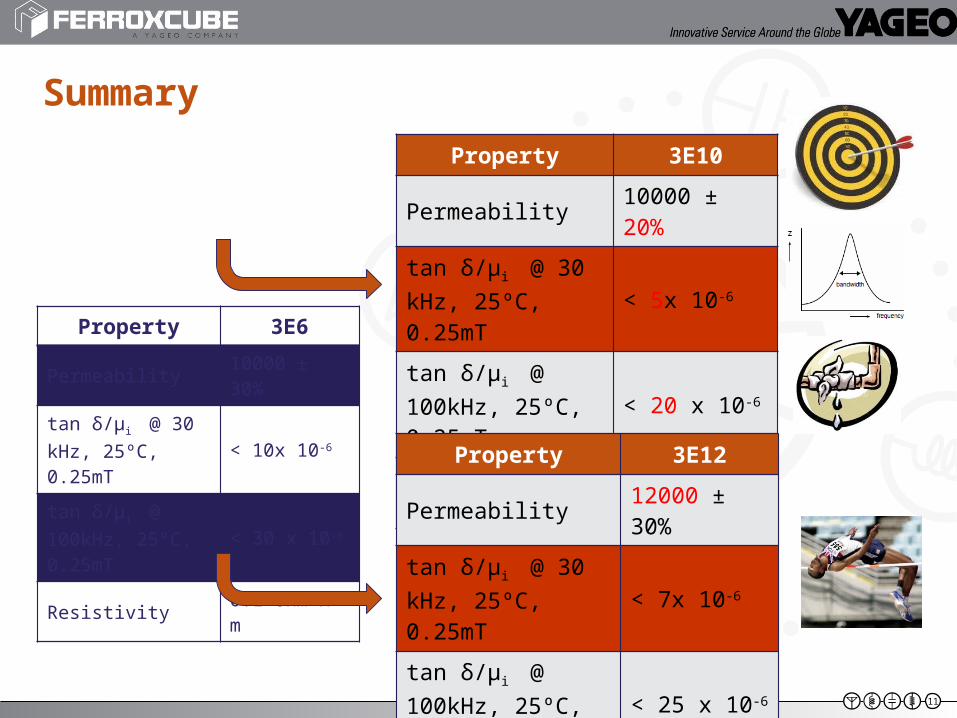
Summary
Property 3E10
Permeability 10000 ± 20%
tan δ/μi @ 30 kHz, 25ºC, 0.25mT
< 5x 10⁻⁶
tan δ/μi @ 100kHz, 25ºC, 0.25mT
< 20 x 10-6
Resistivity 0.5 Ohm x m
Property 3E12
Permeability 12000 ± 30%
tan δ/μi @ 30 kHz, 25ºC, 0.25mT
< 7x 10⁻⁶
tan δ/μi @ 100kHz, 25ºC, 0.25mT
< 25 x 10-6
Resistivity 0.5 Ohm x m
Property 3E6
Permeability 10000 ± 30%
tan δ/μi @ 30 kHz, 25ºC, 0.25mT
< 10x 10-6
tan δ/μi @ 100kHz, 25ºC, 0.25mT
< 30 x 10-6
Resistivity 0.1 Ohm x m
12
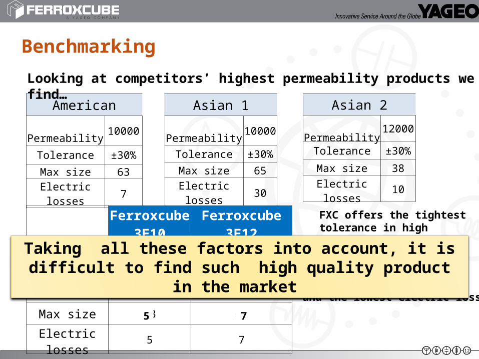
Benchmarking
American
Permeability 10000
Tolerance ±30%
Max size 63
Electric losses 7
Asian 1
Permeability 10000
Tolerance ±30%
Max size 65
Electric losses 30
Looking at competitors’ highest permeability products we find…
Asian 2
Permeability 12000
Tolerance ±30%
Max size 38
Electric losses 10
Ferroxcube3E10
Ferroxcube 3E12
Permeability 10000 12000
Tolerance ±20% ±30%
Max size 63 63
Electric losses 5 75 7
±20%
FXC offers the tightest tolerance in high permeability
the largest size with the maximum permeability
12000
63 63 and the lowest electric losses
Taking all these factors into account, it is difficult to find such high quality product in the market
13