Embed Size (px)
Citation preview
N E W
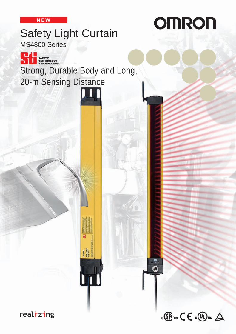
MS4800 Series
Safety Light Curtain
Strong, Durable Body and Long, 20-m Sensing Distance
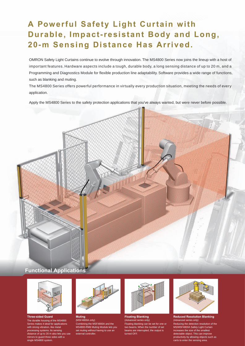
Functional Applications
OMRON Safety Light Curtains continue to evolve through innovation. The MS4800 Series now joins the lineup with a host of
important features. Hardware aspects include a tough, durable body, a long sensing distance of up to 20 m, and a
Programming and Diagnostics Module for flexible production line adaptability. Software provides a wide range of functions,
such as blanking and muting.
The MS4800 Series offers powerful performance in virtually every production situation, meeting the needs of every
application.
Apply the MS4800 Series to the safety protection applications that you've always wanted, but were never before possible.
Three-sided GuardThe durable housing of the MS4800 Series makes it ideal for applications with strong vibration, like metal processing systems. Its sensing distance of up to 20 m also lets you use mirrors to guard three sides with a single MS4800 system.
Muting(MSF4800A only)
Combining the MSF4800A and the MS4800-RM6 Muting Module lets you set muting without having to use an external controller.
Floating Blanking(Advanced series only)
Floating blanking can be set for one or two beams. When the number of set beams are interrupted, the output is turned OFF.
Reduced Resolution Blanking(Advanced series only)
Reducing the detection resolution of the MS/MSF4800A Safety Light Curtain increases the size of the smallest detectable object. This can improve productivity by allowing objects such as carts to enter the sensing area.
Mirror
A Powerfu l Safety L ight Cur ta in wi th Durable , Impact - res istant Body and Long, 20-m Sensing Distance Has Arr ived.
Long Maximum Sensing Distance of 20 m
Series Connection of Up to Four Systems with No Controller Necessary(Allowing a total of 256 beams max.) (MSF4800 only)
Durable Housing with a Thickness of 3 mm Min. Withstands Vibration and Impacts
A Wide Lineup for a Variety of Applications
Unlike conventional Safety Light Curtains, the MS4800 Series uses a thick aluminum case (3 mm at its thinnest parts). This makes it ideal for applications with considerable vibration or impacts.
The long, 20-m maximum sensing distance of the MS4800 Series marks the highest level in the industry. Even in applications where large, complicated machines are guarded, the use of mirrors can reduce the number of Safety Light Curtains required.
Up to four systems can be connected in series (for a total of 256 beams) without having to connect a controller. Models for which the smallest detectable object is different can even be connected to respond flexibly to virtually any application.
Total of 256 beams
Two series are available to meet your needs: the Advanced Series with sophisticated functions and the Basic Series with specialized, basic functions.
3 mm
Advanced SeriesMS/MSF4800A
Basic SeriesMS/MSF4800B
Beam gap Protective height
20 mm 280 to 2,120 mm
30 mm 360 to 2,040 mm
20 mm 280 to 2,120 mm
30 mm 360 to 2,040 mm
Minimum detectable
object
Series Connection Cables (for Transmitter)MS4800-CBLTXIC-@M
Series Connection Cables (for Receiver)MS4800-CBLRXIC-@M
MSF4800 Slave MSF4800A/B Master
Receiver
Transmitter
30-mm diameter 40-mm diameter30-mm diameter40-mm diameter
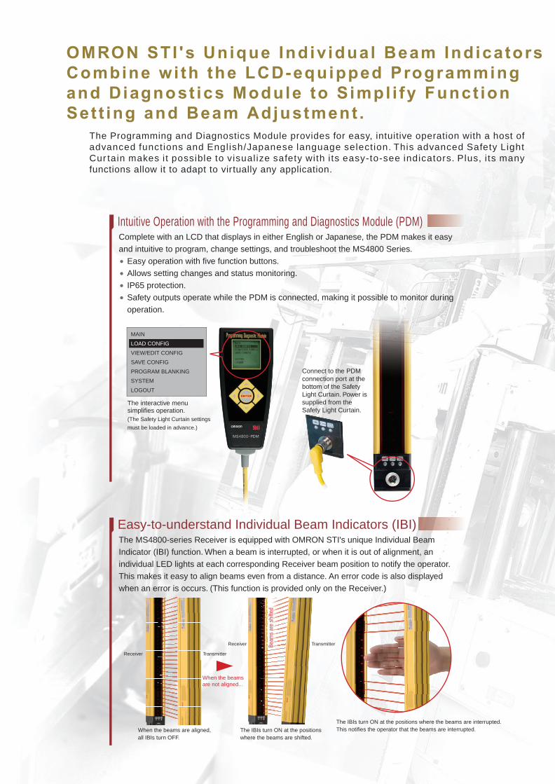
OMRON STI 's Unique Indiv idual Beam Indicators Combine wi th the LCD-equipped Programming and Diagnost ics Module to Simpl i fy Funct ion Set t ing and Beam Adjustment .
Intuitive Operation with the Programming and Diagnostics Module (PDM)
Complies with the Newest Global Safety Standards
Muting Functions for Temporarily Disabling the Safety Light Curtain (MSF4800A only)
Easy-to-understand Individual Beam Indicators (IBI)
Fixed Blanking
Floating Blanking
Monitored Blanking
Reduced Resolution Blanking
Connect to the PDM connection port at the bottom of the Safety Light Curtain. Power is supplied from the Safety Light Curtain.
Four Blanking Functions for Disabling Beams (Advanced series only)
When a machine or a workpiece is present inside the sensing area of the Safety Light Curtain, the output turns OFF and the machine cannot be started. However, a blanking function can be used to disable the appropriate beams of the Safety Light Curtain and allow work to continue without stopping the machine. The MS4800 Series provides four blanking functions to combine both safety and productivity in a wide range of applications.
When the beams are not aligned...
Beam
s ar
e sh
ifted
Receiver
The IBIs turn ON at the positions where the beams are shifted.
When the beams are aligned, all IBIs turn OFF.
The IBIs turn ON at the positions where the beams are interrupted. This notifies the operator that the beams are interrupted.
Transmitter
TransmitterReceiver
This function is used when a machine or workpiece constantly interrupts beams in a part of the sensing area. Fixed Blanking allows the Safety Light Curtain to remain in the RUN state while the obstruction is fixed (as a non-moving object) within the sensing area. The output is turned OFF when a beam other than the set fixed blanking beams is interrupted, or when light is incident on a fixed blanking beam.
This function turns OFF the output when the total number of interrupted beams inside the sensing area exceeds the number of set beams (1 or 2).
This function is used when a machine or workpiece constantly interrupts beams in a part of the sensing area and moves within the sensing area. Monitored Blanking allows the Safety Light Curtain to remain in the RUN state while the obstruction moves within the sensing area. The output is turned OFF when the machine or workpiece disappears from the monitored blanking area that was set by teaching, or when the total number of interrupted beams increases due to a different obstruction.
When the resolution of the MS/MSF4800A is reduced, the size of the smallest detectable object is increased. The output will not turn OFF regardless of how many continuous interrupted beams there are in the sensing area as long as the beams are fewer than the set number (1, 2, or 3 beams). When an object whose size exceeds the set number of beams intrudes, the output is turned OFF. For example, in an application where a conveyor cart approaches a robot work area, the Safety Light Curtain can be set so that it does not detect only the wheels of the cart, allowing the MS/MSF4800A to be used as a presence sensing device.
Complete with an LCD that displays in either English or Japanese, the PDM makes it easy and intuitive to program, change settings, and troubleshoot the MS4800 Series. • Easy operation with five function buttons. • Allows setting changes and status monitoring. • IP65 protection. • Safety outputs operate while the PDM is connected, making it possible to monitor during
operation.
The MS4800-series Safety Light Curtains comply with ISO 13849-1 (Safety Category 4, Ple).They are Type 4 safety light curtains under the IEC 61496-1 and IEC 61496-2 international standards for safety light curtains. They also comply with the IEC 61508 (SIL3) international standard for function safety. These standards ensure safe, reliable use virtually anywhere.
The MS4800-series Receiver is equipped with OMRON STI's unique Individual Beam Indicator (IBI) function. When a beam is interrupted, or when it is out of alignment, an individual LED lights at each corresponding Receiver beam position to notify the operator.
This makes it easy to align beams even from a distance. An error code is also displayed when an error is occurs. (This function is provided only on the Receiver.)
Fixed Blanking
Floating Blanking
The interactive menu simplifies operation.(The Safety Light Curtain settings
must be loaded in advance.)
The Programming and Diagnostics Module provides for easy, intuitive operation with a host of advanced functions and English/Japanese language selection. This advanced Safety Light Cur tain makes i t possible to visual ize safety with i ts easy-to-see indicators. Plus, i ts many functions allow it to adapt to virtually any application.
Reduced Resolution Blanking
In applications where it is necessary for an object to regularly pass through the sensing area, for example to supply workpieces to a machine, the output will turn OFF each time the object passes through, thus lowering productivity. The muting function makes it possible to raise productivity in this kind of application by temporarily disabling the Safety Light Curtain.Select from among four muting modes to match each application with the appropriate number and placement of muting sensors.
The MS4800-RM6 Resource Module is required when using the muting function.
MAIN
LOAD CONFIG
VIEW/EDIT CONFIG
SAVE CONFIG
PROGRAM BLANKING
SYSTEM
LOGOUT

6 Safety Light Curtain MS4800 Series
Safety Light Curtain
MS4800 SeriesSafety Light Curtains with Durable,Impact-resistant Body and Long,20-m Sensing Distance
MS/MSF4800A Advanced Series• Programming and Diagnostics Module (PDM) makes it easy
to set functions.• Series connection is possible only with the MSF4800A.• Blanking can be set.• Muting is possible only with the MSF4800A by using the
MS4800-RM6 Resource Module.
MS/MSF4800B Basic Series• Features all necessary basic Safety Light Curtain functions.• Series connection is possible only with the MSF4800B.• Programming and Diagnostics Module (PDM) makes it easy
to set functions.
Features
Durable Housing Withstands Vibration and ImpactsMS4800 Safety Light Curtains have a thick aluminum case (3 mm at its thinnest parts). This makes them ideal for applications with considerable vibration or impacts.
Long-distance SensingThe maximum sensing distance is 20 meters. This makes the MS4800 Safety Light Curtain well suited to peripheral guard applications using mirrors.
Select the Minimum Detectable Object Size and Protective Height to Match the ApplicationThe minimum detectable object size can be selected as either 30 mm or 40 mm in diameter. When the 30-mm size is selected, the protective height can be from 280 mm to 2,120 mm. When the 40-mm size is selected, the protective height can be from 360 mm to 2,040 mm.
Individual Beam Indicators (IBI)When the infrared beams are interrupted or when the beams are not correctly aligned, Individual Beam Indicators on the Receiver light. This makes it easy to align beams even from a distance.
Series Connection Function (MSF4800 Only)Up to four MSF4800 Safety Light Curtains can be “daisy-chained” in series. When using this configuration, the total
number of beams must not exceed 256. Each MSF4800 in the configuration is called a segment. The segment connected to the control system and power supply is called the master segment, and the other segments are called slave segments. There must be one master segment. When connecting two segments, use one master segment and one slave segment. For three segments, use one master segment and two slave segments; and for four segments, use one master segment and three slave segments.Note: A slave segment cannot be used alone.
No Special Controller A Category 4 safety circuit can be configured using only Receivers and Transmitters.
Test Input (MTS)This function lets you use an external signal to halt the light emission of the Safety Light Curtain to check the operation of the safety system when the Safety Light Curtain is interrupted.
External Device Monitoring (EDM, MPCE Monitoring)This function detects operating faults such as contact welding of the external device (relay) that is used to control a machine.
Scan Code for Mutual Interference ReductionSwitching the two types of scan codes helps to reduce mutual interference between adjacent Safety Light Curtains.
Complies with the Newest Global Safety Standards
Be sure to read the Precautions for Safe Use on page 31.
Safety Light Curtain MS4800 Series 7
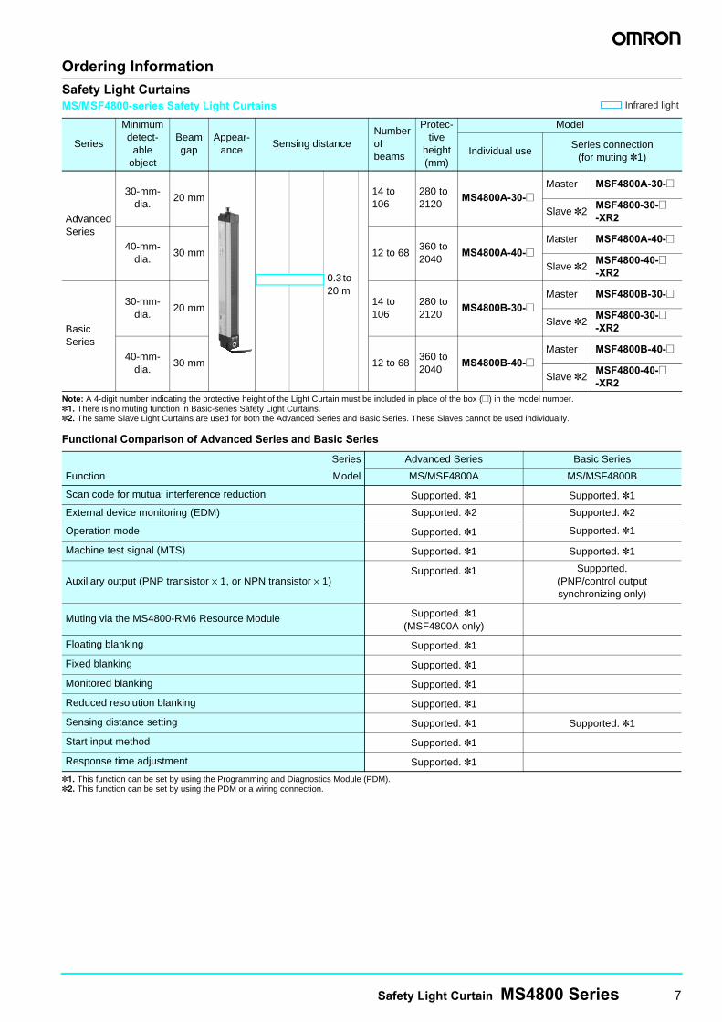
Ordering InformationSafety Light CurtainsMS/MSF4800-series Safety Light Curtains
Note: A 4-digit number indicating the protective height of the Light Curtain must be included in place of the box (@) in the model number.*1. There is no muting function in Basic-series Safety Light Curtains.*2. The same Slave Light Curtains are used for both the Advanced Series and Basic Series. These Slaves cannot be used individually.
Functional Comparison of Advanced Series and Basic Series
*1. This function can be set by using the Programming and Diagnostics Module (PDM).*2. This function can be set by using the PDM or a wiring connection.
Series
Minimum detect-
ableobject
Beamgap
Appear-ance
Sensing distanceNumberof beams
Protec-tive
height (mm)
Model
Individual useSeries connection
(for muting *1)
AdvancedSeries
30-mm-dia.
20 mm14 to 106
280 to 2120
MS4800A-30-@Master MSF4800A-30-@
Slave *2MSF4800-30-@-XR2
40-mm-dia.
30 mm 12 to 68360 to 2040
MS4800A-40-@Master MSF4800A-40-@
Slave *2MSF4800-40-@-XR2
Basic Series
30-mm-dia.
20 mm14 to 106
280 to 2120
MS4800B-30-@Master MSF4800B-30-@
Slave *2MSF4800-30-@-XR2
40-mm-dia.
30 mm 12 to 68360 to 2040
MS4800B-40-@Master MSF4800B-40-@
Slave *2MSF4800-40-@-XR2
Series Advanced Series Basic Series
Function Model MS/MSF4800A MS/MSF4800B
Scan code for mutual interference reduction Supported. *1 Supported. *1
External device monitoring (EDM) Supported. *2 Supported. *2
Operation mode Supported. *1 Supported. *1
Machine test signal (MTS) Supported. *1 Supported. *1
Auxiliary output (PNP transistor × 1, or NPN transistor × 1)Supported. *1 Supported.
(PNP/control output synchronizing only)
Muting via the MS4800-RM6 Resource Module Supported. *1(MSF4800A only)
Floating blanking Supported. *1
Fixed blanking Supported. *1
Monitored blanking Supported. *1
Reduced resolution blanking Supported. *1
Sensing distance setting Supported. *1 Supported. *1
Start input method Supported. *1
Response time adjustment Supported. *1
Infrared light
0.3 to 20 m
8 Safety Light Curtain MS4800 Series
Safety Light Curtain Model ListAdvanced-series Curtains Used Individually (Minimum detectable object: 30-mm dia., Beam gap: 20 mm)
Advanced-series Curtains Used Individually (Minimum detectable object: 40-mm dia., Beam gap: 30 mm)
Basic-series Curtains Used Individually (Minimum detectable object: 30-mm dia., Beam gap: 20 mm)
Basic-series Curtains Used Individually(Minimum detectable object: 40-mm dia., Beam gap: 30 mm)
Model Number of beams Protective height (mm)MS4800A-30-0280 14 280MS4800A-30-0320 16 320MS4800A-30-0360 18 360MS4800A-30-0400 20 400MS4800A-30-0440 22 440MS4800A-30-0480 24 480MS4800A-30-0520 26 520MS4800A-30-0560 28 560MS4800A-30-0600 30 600MS4800A-30-0640 32 640MS4800A-30-0680 34 680MS4800A-30-0720 36 720MS4800A-30-0760 38 760MS4800A-30-0800 40 800MS4800A-30-0840 42 840MS4800A-30-0880 44 880MS4800A-30-0920 46 920MS4800A-30-0960 48 960MS4800A-30-1000 50 1000MS4800A-30-1040 52 1040MS4800A-30-1080 54 1080MS4800A-30-1120 56 1120MS4800A-30-1160 58 1160MS4800A-30-1200 60 1200MS4800A-30-1240 62 1240MS4800A-30-1280 64 1280MS4800A-30-1320 66 1320MS4800A-30-1360 68 1360MS4800A-30-1400 70 1400MS4800A-30-1440 72 1440MS4800A-30-1480 74 1480MS4800A-30-1520 76 1520MS4800A-30-1560 78 1560MS4800A-30-1600 80 1600MS4800A-30-1640 82 1640MS4800A-30-1680 84 1680MS4800A-30-1720 86 1720MS4800A-30-1760 88 1760MS4800A-30-1800 90 1800MS4800A-30-1840 92 1840MS4800A-30-1880 94 1880MS4800A-30-1920 96 1920MS4800A-30-1960 98 1960MS4800A-30-2000 100 2000MS4800A-30-2040 102 2040MS4800A-30-2080 104 2080MS4800A-30-2120 106 2120
Model Number of beams Protective height (mm)MS4800A-40-0360 12 360MS4800A-40-0480 16 480MS4800A-40-0600 20 600MS4800A-40-0720 24 720MS4800A-40-0840 28 840MS4800A-40-0960 32 960MS4800A-40-1080 36 1080MS4800A-40-1200 40 1200MS4800A-40-1320 44 1320MS4800A-40-1440 48 1440MS4800A-40-1560 52 1560MS4800A-40-1680 56 1680MS4800A-40-1800 60 1800MS4800A-40-1920 64 1920MS4800A-40-2040 68 2040
Model Number of beams Protective height (mm)MS4800B-30-0280 14 280MS4800B-30-0320 16 320MS4800B-30-0360 18 360MS4800B-30-0400 20 400MS4800B-30-0440 22 440MS4800B-30-0480 24 480MS4800B-30-0520 26 520MS4800B-30-0560 28 560MS4800B-30-0600 30 600MS4800B-30-0640 32 640MS4800B-30-0680 34 680MS4800B-30-0720 36 720MS4800B-30-0760 38 760MS4800B-30-0800 40 800MS4800B-30-0840 42 840MS4800B-30-0880 44 880MS4800B-30-0920 46 920MS4800B-30-0960 48 960MS4800B-30-1000 50 1000MS4800B-30-1040 52 1040MS4800B-30-1080 54 1080MS4800B-30-1120 56 1120MS4800B-30-1160 58 1160MS4800B-30-1200 60 1200MS4800B-30-1240 62 1240MS4800B-30-1280 64 1280MS4800B-30-1320 66 1320MS4800B-30-1360 68 1360MS4800B-30-1400 70 1400MS4800B-30-1440 72 1440MS4800B-30-1480 74 1480MS4800B-30-1520 76 1520MS4800B-30-1560 78 1560MS4800B-30-1600 80 1600MS4800B-30-1640 82 1640MS4800B-30-1680 84 1680MS4800B-30-1720 86 1720MS4800B-30-1760 88 1760MS4800B-30-1800 90 1800MS4800B-30-1840 92 1840MS4800B-30-1880 94 1880MS4800B-30-1920 96 1920MS4800B-30-1960 98 1960MS4800B-30-2000 100 2000MS4800B-30-2040 102 2040MS4800B-30-2080 104 2080MS4800B-30-2120 106 2120
Model Number of beams Protective height (mm)MS4800B-40-0360 12 360MS4800B-40-0480 16 480MS4800B-40-0600 20 600MS4800B-40-0720 24 720MS4800B-40-0840 28 840MS4800B-40-0960 32 960MS4800B-40-1080 36 1080MS4800B-40-1200 40 1200MS4800B-40-1320 44 1320MS4800B-40-1440 48 1440MS4800B-40-1560 52 1560MS4800B-40-1680 56 1680MS4800B-40-1800 60 1800MS4800B-40-1920 64 1920MS4800B-40-2040 68 2040
Safety Light Curtain MS4800 Series 9
Advanced-series Curtains Connected in Series (Minimum detectable object: 30-mm dia., Beam gap: 20 mm)Masters
Advanced-series Curtains Connected in Series (Minimum detectable object: 40-mm dia., Beam gap: 30 mm)Masters
Basic-series Curtains Connected in Series (Minimum detectable object: 30-mm dia., Beam gap: 20 mm)Masters
Basic-series Curtains Connected in Series (Minimum detectable object: 40-mm dia., Beam gap: 30 mm)Masters
Model Number of beams Protective height (mm)MSF4800A-30-0280 14 280MSF4800A-30-0320 16 320MSF4800A-30-0360 18 360MSF4800A-30-0400 20 400MSF4800A-30-0440 22 440MSF4800A-30-0480 24 480MSF4800A-30-0520 26 520MSF4800A-30-0560 28 560MSF4800A-30-0600 30 600MSF4800A-30-0640 32 640MSF4800A-30-0680 34 680MSF4800A-30-0720 36 720MSF4800A-30-0760 38 760MSF4800A-30-0800 40 800MSF4800A-30-0840 42 840MSF4800A-30-0880 44 880MSF4800A-30-0920 46 920MSF4800A-30-0960 48 960MSF4800A-30-1000 50 1000MSF4800A-30-1040 52 1040MSF4800A-30-1080 54 1080MSF4800A-30-1120 56 1120MSF4800A-30-1160 58 1160MSF4800A-30-1200 60 1200MSF4800A-30-1240 62 1240MSF4800A-30-1280 64 1280MSF4800A-30-1320 66 1320MSF4800A-30-1360 68 1360MSF4800A-30-1400 70 1400MSF4800A-30-1440 72 1440MSF4800A-30-1480 74 1480MSF4800A-30-1520 76 1520MSF4800A-30-1560 78 1560MSF4800A-30-1600 80 1600MSF4800A-30-1640 82 1640MSF4800A-30-1680 84 1680MSF4800A-30-1720 86 1720MSF4800A-30-1760 88 1760MSF4800A-30-1800 90 1800MSF4800A-30-1840 92 1840MSF4800A-30-1880 94 1880MSF4800A-30-1920 96 1920MSF4800A-30-1960 98 1960MSF4800A-30-2000 100 2000MSF4800A-30-2040 102 2040MSF4800A-30-2080 104 2080MSF4800A-30-2120 106 2120
Model Number of beams Protective height (mm)MSF4800A-40-0360 12 360MSF4800A-40-0480 16 480MSF4800A-40-0600 20 600MSF4800A-40-0720 24 720MSF4800A-40-0840 28 840MSF4800A-40-0960 32 960MSF4800A-40-1080 36 1080MSF4800A-40-1200 40 1200MSF4800A-40-1320 44 1320MSF4800A-40-1440 48 1440MSF4800A-40-1560 52 1560MSF4800A-40-1680 56 1680MSF4800A-40-1800 60 1800MSF4800A-40-1920 64 1920MSF4800A-40-2040 68 2040
Model Number of beams Protective height (mm)MSF4800B-30-0280 14 280MSF4800B-30-0320 16 320MSF4800B-30-0360 18 360MSF4800B-30-0400 20 400MSF4800B-30-0440 22 440MSF4800B-30-0480 24 480MSF4800B-30-0520 26 520MSF4800B-30-0560 28 560MSF4800B-30-0600 30 600MSF4800B-30-0640 32 640MSF4800B-30-0680 34 680MSF4800B-30-0720 36 720MSF4800B-30-0760 38 760MSF4800B-30-0800 40 800MSF4800B-30-0840 42 840MSF4800B-30-0880 44 880MSF4800B-30-0920 46 920MSF4800B-30-0960 48 960MSF4800B-30-1000 50 1000MSF4800B-30-1040 52 1040MSF4800B-30-1080 54 1080MSF4800B-30-1120 56 1120MSF4800B-30-1160 58 1160MSF4800B-30-1200 60 1200MSF4800B-30-1240 62 1240MSF4800B-30-1280 64 1280MSF4800B-30-1320 66 1320MSF4800B-30-1360 68 1360MSF4800B-30-1400 70 1400MSF4800B-30-1440 72 1440MSF4800B-30-1480 74 1480MSF4800B-30-1520 76 1520MSF4800B-30-1560 78 1560MSF4800B-30-1600 80 1600MSF4800B-30-1640 82 1640MSF4800B-30-1680 84 1680MSF4800B-30-1720 86 1720MSF4800B-30-1760 88 1760MSF4800B-30-1800 90 1800MSF4800B-30-1840 92 1840MSF4800B-30-1880 94 1880MSF4800B-30-1920 96 1920MSF4800B-30-1960 98 1960MSF4800B-30-2000 100 2000MSF4800B-30-2040 102 2040MSF4800B-30-2080 104 2080MSF4800B-30-2120 106 2120
Model Number of beams Protective height (mm)MSF4800B-40-0360 12 360MSF4800B-40-0480 16 480MSF4800B-40-0600 20 600MSF4800B-40-0720 24 720MSF4800B-40-0840 28 840MSF4800B-40-0960 32 960MSF4800B-40-1080 36 1080MSF4800B-40-1200 40 1200MSF4800B-40-1320 44 1320MSF4800B-40-1440 48 1440MSF4800B-40-1560 52 1560MSF4800B-40-1680 56 1680MSF4800B-40-1800 60 1800MSF4800B-40-1920 64 1920MSF4800B-40-2040 68 2040
10 Safety Light Curtain MS4800 Series
Advanced Series/Basic-series Curtains Connected in Series (Minimum detectable object: 30-mm dia., Beam gap: 20 mm)Slaves
Advanced Series/Basic-series Curtains Connected in Series (Minimum detectable object: 40-mm dia., Beam gap: 30 mm)Slaves
Model Number of beams Protective height (mm)MSF4800-30-0280-XR2 14 280MSF4800-30-0320-XR2 16 320MSF4800-30-0360-XR2 18 360MSF4800-30-0400-XR2 20 400MSF4800-30-0440-XR2 22 440MSF4800-30-0480-XR2 24 480MSF4800-30-0520-XR2 26 520MSF4800-30-0560-XR2 28 560MSF4800-30-0600-XR2 30 600MSF4800-30-0640-XR2 32 640MSF4800-30-0680-XR2 34 680MSF4800-30-0720-XR2 36 720MSF4800-30-0760-XR2 38 760MSF4800-30-0800-XR2 40 800MSF4800-30-0840-XR2 42 840MSF4800-30-0880-XR2 44 880MSF4800-30-0920-XR2 46 920MSF4800-30-0960-XR2 48 960MSF4800-30-1000-XR2 50 1000MSF4800-30-1040-XR2 52 1040MSF4800-30-1080-XR2 54 1080MSF4800-30-1120-XR2 56 1120MSF4800-30-1160-XR2 58 1160MSF4800-30-1200-XR2 60 1200MSF4800-30-1240-XR2 62 1240MSF4800-30-1280-XR2 64 1280MSF4800-30-1320-XR2 66 1320MSF4800-30-1360-XR2 68 1360MSF4800-30-1400-XR2 70 1400MSF4800-30-1440-XR2 72 1440MSF4800-30-1480-XR2 74 1480MSF4800-30-1520-XR2 76 1520MSF4800-30-1560-XR2 78 1560MSF4800-30-1600-XR2 80 1600MSF4800-30-1640-XR2 82 1640MSF4800-30-1680-XR2 84 1680MSF4800-30-1720-XR2 86 1720MSF4800-30-1760-XR2 88 1760MSF4800-30-1800-XR2 90 1800MSF4800-30-1840-XR2 92 1840MSF4800-30-1880-XR2 94 1880MSF4800-30-1920-XR2 96 1920MSF4800-30-1960-XR2 98 1960MSF4800-30-2000-XR2 100 2000MSF4800-30-2040-XR2 102 2040MSF4800-30-2080-XR2 104 2080MSF4800-30-2120-XR2 106 2120
Model Number of beams Protective height (mm)MSF4800-40-0360-XR2 12 360MSF4800-40-0480-XR2 16 480MSF4800-40-0600-XR2 20 600MSF4800-40-0720-XR2 24 720MSF4800-40-0840-XR2 28 840MSF4800-40-0960-XR2 32 960MSF4800-40-1080-XR2 36 1080MSF4800-40-1200-XR2 40 1200MSF4800-40-1320-XR2 44 1320MSF4800-40-1440-XR2 48 1440MSF4800-40-1560-XR2 52 1560MSF4800-40-1680-XR2 56 1680MSF4800-40-1800-XR2 60 1800MSF4800-40-1920-XR2 64 1920MSF4800-40-2040-XR2 68 2040
Safety Light Curtain MS4800 Series 11
Accessories (Sold Separately)Connector Cables with a Connector on One End
Connector Cables with Connectors on Both Ends
Series Connection Cables
Type Appearance SpecificationsCable length
Model Application
Transmitter Cables
M12 connector
(5-pin)
10 m MS4800-CBLTX-10M
For wiring safety circuits containing individual relays with forcibly guided contacts, safety relay units, safety controllers, etc.
15 m MS4800-CBLTX-15M
30 m MS4800-CBLTX-30M
Receiver Cables
M12 connector
(8-pin)
10 m MS4800-CBLRX-10M
15 m MS4800-CBLRX-15M
30 m MS4800-CBLRX-30M
Type Appearance SpecificationsCable length
Model Application
Transmitter Cables
M12 connector
(5-pin)
5 m MS4800-CBLTXT-05M
Extension cables for connector cables with a connector on one end.
10 m MS4800-CBLTXT-10M
15 m MS4800-CBLTXT-15M
25 m MS4800-CBLTXT-25M
Receiver Cables
M12 connector
(8-pin)
5 m MS4800-CBLRXT-05M
10 m MS4800-CBLRXT-10M
15 m MS4800-CBLRXT-15M
25 m MS4800-CBLRXT-25M
Type Appearance SpecificationsCable length
Model Application
Transmitter Cables
M12 connector
(4-pin)
0.3 m MS4800-CBLTXIC-003M
For series connection.
0.5 m MS4800-CBLTXIC-005M1 m MS4800-CBLTXIC-01M2 m MS4800-CBLTXIC-02M3 m MS4800-CBLTXIC-03M5 m MS4800-CBLTXIC-05M
10 m MS4800-CBLTXIC-10M
Receiver Cables
M12 connector
(4-pin)
0.3 m MS4800-CBLRXIC-003M0.5 m MS4800-CBLRXIC-005M
1 m MS4800-CBLRXIC-01M2 m MS4800-CBLRXIC-02M3 m MS4800-CBLRXIC-03M5 m MS4800-CBLRXIC-05M
10 m MS4800-CBLRXIC-10M
12 Safety Light Curtain MS4800 Series
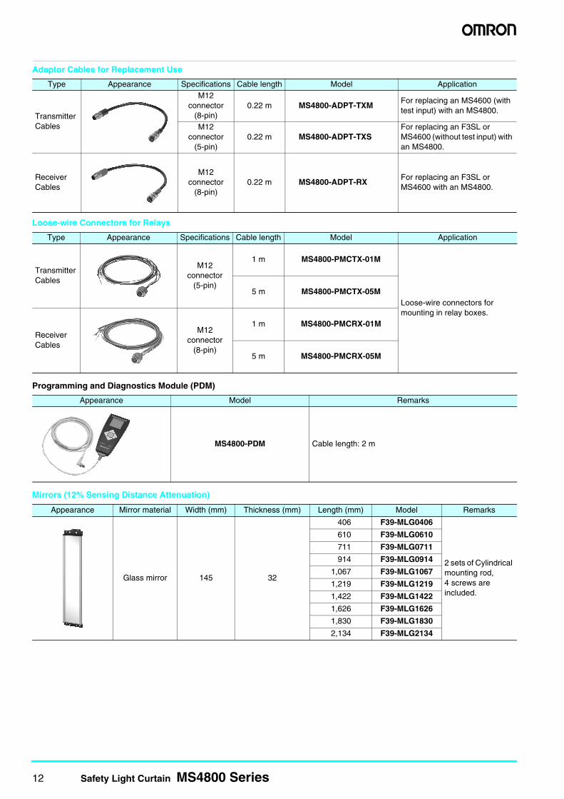
Adaptor Cables for Replacement Use
Loose-wire Connectors for Relays
Programming and Diagnostics Module (PDM)
Mirrors (12% Sensing Distance Attenuation)
Type Appearance Specifications Cable length Model Application
Transmitter Cables
M12 connector
(8-pin)0.22 m MS4800-ADPT-TXM
For replacing an MS4600 (with test input) with an MS4800.
M12 connector
(5-pin)0.22 m MS4800-ADPT-TXS
For replacing an F3SL or MS4600 (without test input) with an MS4800.
Receiver Cables
M12 connector
(8-pin)0.22 m MS4800-ADPT-RX
For replacing an F3SL or MS4600 with an MS4800.
Type Appearance Specifications Cable length Model Application
Transmitter Cables
M12 connector
(5-pin)
1 m MS4800-PMCTX-01M
Loose-wire connectors for mounting in relay boxes.
5 m MS4800-PMCTX-05M
Receiver Cables
M12 connector
(8-pin)
1 m MS4800-PMCRX-01M
5 m MS4800-PMCRX-05M
Appearance Model Remarks
MS4800-PDM Cable length: 2 m
Appearance Mirror material Width (mm) Thickness (mm) Length (mm) Model Remarks
Glass mirror 145 32
406 F39-MLG0406
2 sets of Cylindrical mounting rod,4 screws are included.
610 F39-MLG0610
711 F39-MLG0711
914 F39-MLG0914
1,067 F39-MLG1067
1,219 F39-MLG1219
1,422 F39-MLG1422
1,626 F39-MLG1626
1,830 F39-MLG1830
2,134 F39-MLG2134
Safety Light Curtain MS4800 Series 13
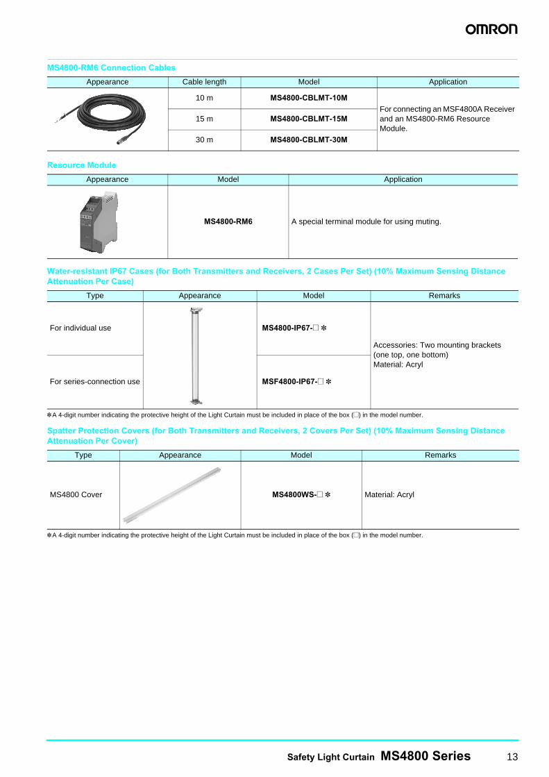
MS4800-RM6 Connection Cables
Resource Module
Water-resistant IP67 Cases (for Both Transmitters and Receivers, 2 Cases Per Set) (10% Maximum Sensing Distance Attenuation Per Case)
*A 4-digit number indicating the protective height of the Light Curtain must be included in place of the box (@) in the model number.
Spatter Protection Covers (for Both Transmitters and Receivers, 2 Covers Per Set) (10% Maximum Sensing Distance Attenuation Per Cover)
*A 4-digit number indicating the protective height of the Light Curtain must be included in place of the box (@) in the model number.
Appearance Cable length Model Application
10 m MS4800-CBLMT-10MFor connecting an MSF4800A Receiver and an MS4800-RM6 Resource Module.
15 m MS4800-CBLMT-15M
30 m MS4800-CBLMT-30M
Appearance Model Application
MS4800-RM6 A special terminal module for using muting.
Type Appearance Model Remarks
For individual use MS4800-IP67-@ *
Accessories: Two mounting brackets (one top, one bottom)Material: Acryl
For series-connection use MSF4800-IP67-@ *
Type Appearance Model Remarks
MS4800 Cover MS4800WS-@ * Material: Acryl
14 Safety Light Curtain MS4800 Series
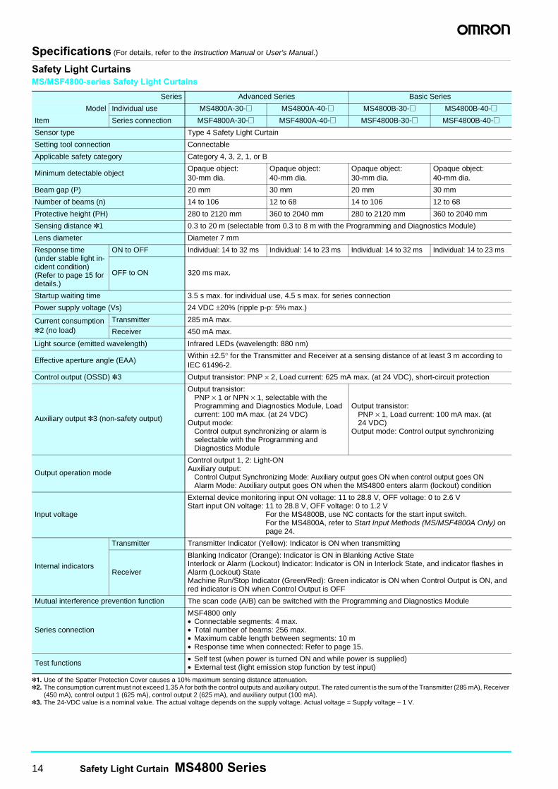
Specifications (For details, refer to the Instruction Manual or User's Manual.)
Safety Light CurtainsMS/MSF4800-series Safety Light Curtains
*1. Use of the Spatter Protection Cover causes a 10% maximum sensing distance attenuation.*2. The consumption current must not exceed 1.35 A for both the control outputs and auxiliary output. The rated current is the sum of the Transmitter (285 mA), Receiver
(450 mA), control output 1 (625 mA), control output 2 (625 mA), and auxiliary output (100 mA).*3. The 24-VDC value is a nominal value. The actual voltage depends on the supply voltage. Actual voltage = Supply voltage − 1 V.
Series Advanced Series Basic Series
Model Individual use MS4800A-30-@ MS4800A-40-@ MS4800B-30-@ MS4800B-40-@Item Series connection MSF4800A-30-@ MSF4800A-40-@ MSF4800B-30-@ MSF4800B-40-@Sensor type Type 4 Safety Light Curtain
Setting tool connection Connectable
Applicable safety category Category 4, 3, 2, 1, or B
Minimum detectable objectOpaque object: 30-mm dia.
Opaque object: 40-mm dia.
Opaque object: 30-mm dia.
Opaque object: 40-mm dia.
Beam gap (P) 20 mm 30 mm 20 mm 30 mm
Number of beams (n) 14 to 106 12 to 68 14 to 106 12 to 68
Protective height (PH) 280 to 2120 mm 360 to 2040 mm 280 to 2120 mm 360 to 2040 mm
Sensing distance *1 0.3 to 20 m (selectable from 0.3 to 8 m with the Programming and Diagnostics Module)
Lens diameter Diameter 7 mm
Response time (under stable light in-cident condition) (Refer to page 15 for details.)
ON to OFF Individual: 14 to 32 ms Individual: 14 to 23 ms Individual: 14 to 32 ms Individual: 14 to 23 ms
OFF to ON 320 ms max.
Startup waiting time 3.5 s max. for individual use, 4.5 s max. for series connection
Power supply voltage (Vs) 24 VDC ±20% (ripple p-p: 5% max.)
Current consumption *2 (no load)
Transmitter 285 mA max.
Receiver 450 mA max.
Light source (emitted wavelength) Infrared LEDs (wavelength: 880 nm)
Effective aperture angle (EAA)Within ±2.5° for the Transmitter and Receiver at a sensing distance of at least 3 m according to IEC 61496-2.
Control output (OSSD) *3 Output transistor: PNP × 2, Load current: 625 mA max. (at 24 VDC), short-circuit protection
Auxiliary output *3 (non-safety output)
Output transistor: PNP × 1 or NPN × 1, selectable with the Programming and Diagnostics Module, Load current: 100 mA max. (at 24 VDC)
Output mode:Control output synchronizing or alarm is selectable with the Programming and Diagnostics Module
Output transistor: PNP × 1, Load current: 100 mA max. (at 24 VDC)
Output mode: Control output synchronizing
Output operation mode
Control output 1, 2: Light-ONAuxiliary output:
Control Output Synchronizing Mode: Auxiliary output goes ON when control output goes ONAlarm Mode: Auxiliary output goes ON when the MS4800 enters alarm (lockout) condition
Input voltage
External device monitoring input ON voltage: 11 to 28.8 V, OFF voltage: 0 to 2.6 VStart input ON voltage: 11 to 28.8 V, OFF voltage: 0 to 1.2 V
For the MS4800B, use NC contacts for the start input switch.For the MS4800A, refer to Start Input Methods (MS/MSF4800A Only) on page 24.
Internal indicators
Transmitter Transmitter Indicator (Yellow): Indicator is ON when transmitting
Receiver
Blanking Indicator (Orange): Indicator is ON in Blanking Active StateInterlock or Alarm (Lockout) Indicator: Indicator is ON in Interlock State, and indicator flashes in Alarm (Lockout) StateMachine Run/Stop Indicator (Green/Red): Green indicator is ON when Control Output is ON, and red indicator is ON when Control Output is OFF
Mutual interference prevention function The scan code (A/B) can be switched with the Programming and Diagnostics Module
Series connection
MSF4800 only• Connectable segments: 4 max.• Total number of beams: 256 max.• Maximum cable length between segments: 10 m• Response time when connected: Refer to page 15.
Test functions • Self test (when power is turned ON and while power is supplied)• External test (light emission stop function by test input)
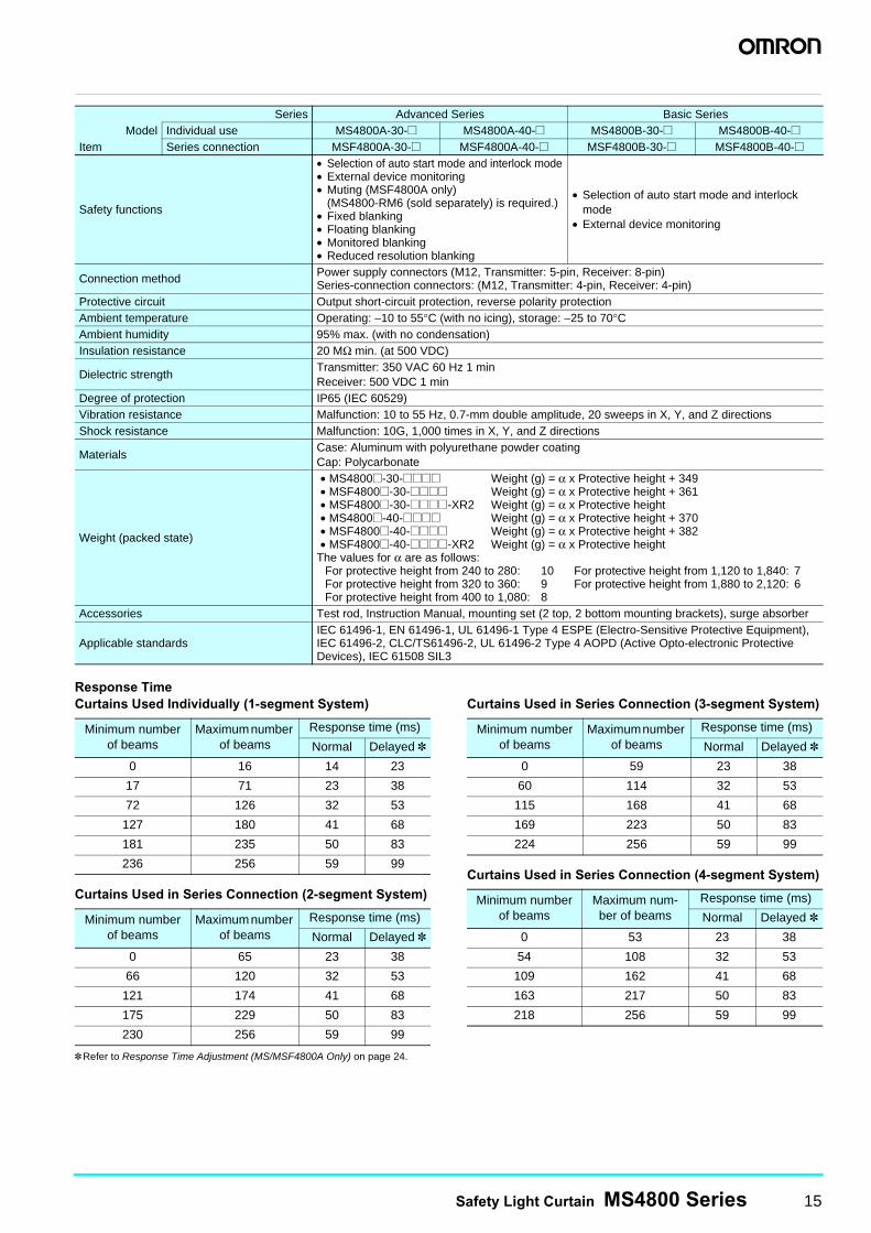
Safety Light Curtain MS4800 Series 15
Response TimeCurtains Used Individually (1-segment System)
Curtains Used in Series Connection (2-segment System)
Curtains Used in Series Connection (3-segment System)
Curtains Used in Series Connection (4-segment System)
*Refer to Response Time Adjustment (MS/MSF4800A Only) on page 24.
Series Advanced Series Basic SeriesModel Individual use MS4800A-30-@ MS4800A-40-@ MS4800B-30-@ MS4800B-40-@
Item Series connection MSF4800A-30-@ MSF4800A-40-@ MSF4800B-30-@ MSF4800B-40-@
Safety functions
• Selection of auto start mode and interlock mode• External device monitoring• Muting (MSF4800A only)
(MS4800-RM6 (sold separately) is required.)• Fixed blanking• Floating blanking• Monitored blanking• Reduced resolution blanking
• Selection of auto start mode and interlock mode
• External device monitoring
Connection method Power supply connectors (M12, Transmitter: 5-pin, Receiver: 8-pin)Series-connection connectors: (M12, Transmitter: 4-pin, Receiver: 4-pin)
Protective circuit Output short-circuit protection, reverse polarity protectionAmbient temperature Operating: −10 to 55°C (with no icing), storage: −25 to 70°CAmbient humidity 95% max. (with no condensation)Insulation resistance 20 MΩ min. (at 500 VDC)
Dielectric strengthTransmitter: 350 VAC 60 Hz 1 minReceiver: 500 VDC 1 min
Degree of protection IP65 (IEC 60529)Vibration resistance Malfunction: 10 to 55 Hz, 0.7-mm double amplitude, 20 sweeps in X, Y, and Z directionsShock resistance Malfunction: 10G, 1,000 times in X, Y, and Z directions
MaterialsCase: Aluminum with polyurethane powder coatingCap: Polycarbonate
Weight (packed state)
• MS4800@-30-@@@@ Weight (g) = α x Protective height + 349• MSF4800@-30-@@@@ Weight (g) = α x Protective height + 361• MSF4800@-30-@@@@-XR2 Weight (g) = α x Protective height • MS4800@-40-@@@@ Weight (g) = α x Protective height + 370• MSF4800@-40-@@@@ Weight (g) = α x Protective height + 382• MSF4800@-40-@@@@-XR2 Weight (g) = α x Protective height
The values for α are as follows:For protective height from 240 to 280: 10 For protective height from 1,120 to 1,840: 7For protective height from 320 to 360: 9 For protective height from 1,880 to 2,120: 6For protective height from 400 to 1,080: 8
Accessories Test rod, Instruction Manual, mounting set (2 top, 2 bottom mounting brackets), surge absorber
Applicable standardsIEC 61496-1, EN 61496-1, UL 61496-1 Type 4 ESPE (Electro-Sensitive Protective Equipment), IEC 61496-2, CLC/TS61496-2, UL 61496-2 Type 4 AOPD (Active Opto-electronic Protective Devices), IEC 61508 SIL3
Minimum number of beams
Maximum number of beams
Response time (ms)
Normal Delayed *0 16 14 23
17 71 23 38
72 126 32 53
127 180 41 68
181 235 50 83
236 256 59 99
Minimum number of beams
Maximum number of beams
Response time (ms)
Normal Delayed *0 65 23 38
66 120 32 53
121 174 41 68
175 229 50 83
230 256 59 99
Minimum number of beams
Maximum number of beams
Response time (ms)
Normal Delayed *0 59 23 38
60 114 32 53
115 168 41 68
169 223 50 83
224 256 59 99
Minimum number of beams
Maximum num-ber of beams
Response time (ms)
Normal Delayed *0 53 23 38
54 108 32 53
109 162 41 68
163 217 50 83
218 256 59 99
16 Safety Light Curtain MS4800 Series
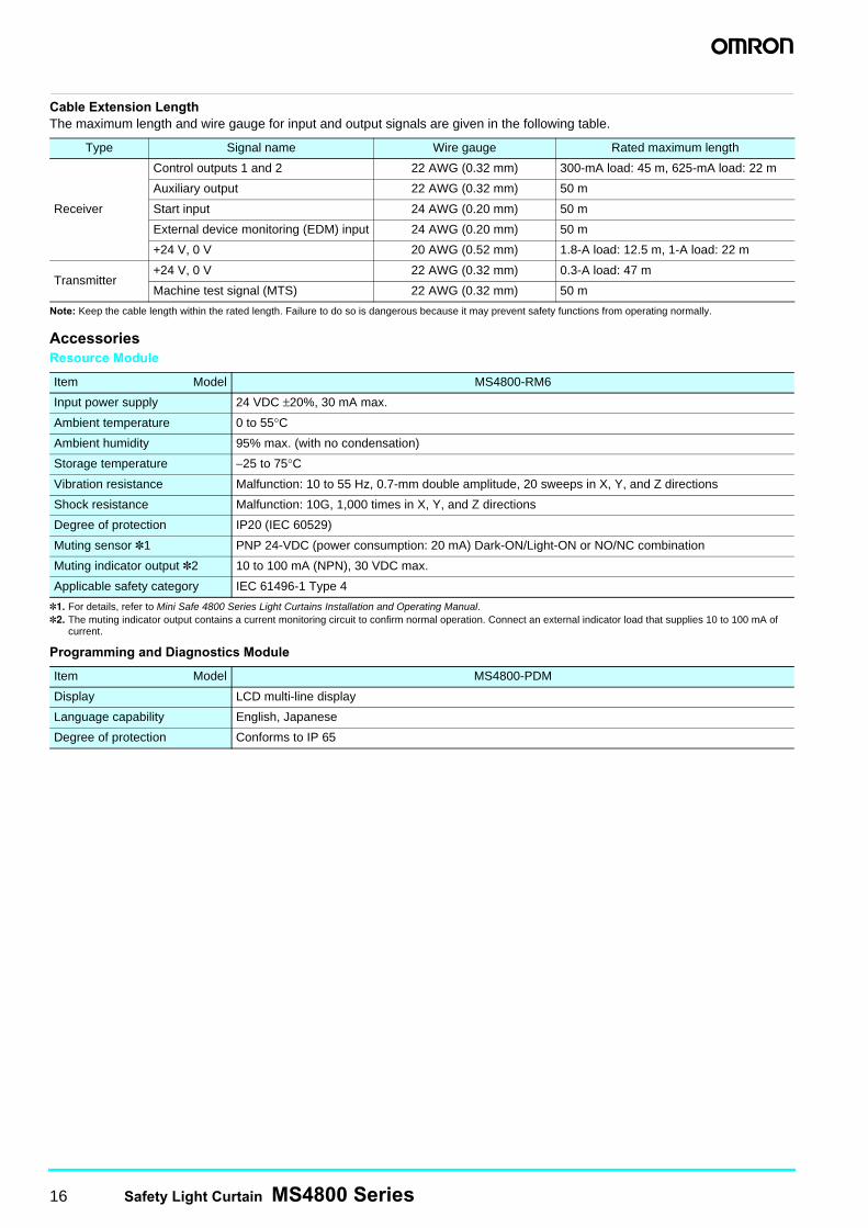
Cable Extension LengthThe maximum length and wire gauge for input and output signals are given in the following table.
Note: Keep the cable length within the rated length. Failure to do so is dangerous because it may prevent safety functions from operating normally.
AccessoriesResource Module
*1. For details, refer to Mini Safe 4800 Series Light Curtains Installation and Operating Manual.*2. The muting indicator output contains a current monitoring circuit to confirm normal operation. Connect an external indicator load that supplies 10 to 100 mA of
current.
Programming and Diagnostics Module
Type Signal name Wire gauge Rated maximum length
Receiver
Control outputs 1 and 2 22 AWG (0.32 mm) 300-mA load: 45 m, 625-mA load: 22 m
Auxiliary output 22 AWG (0.32 mm) 50 m
Start input 24 AWG (0.20 mm) 50 m
External device monitoring (EDM) input 24 AWG (0.20 mm) 50 m
+24 V, 0 V 20 AWG (0.52 mm) 1.8-A load: 12.5 m, 1-A load: 22 m
Transmitter+24 V, 0 V 22 AWG (0.32 mm) 0.3-A load: 47 m
Machine test signal (MTS) 22 AWG (0.32 mm) 50 m
Item Model MS4800-RM6
Input power supply 24 VDC ±20%, 30 mA max.
Ambient temperature 0 to 55°C
Ambient humidity 95% max. (with no condensation)
Storage temperature −25 to 75°C
Vibration resistance Malfunction: 10 to 55 Hz, 0.7-mm double amplitude, 20 sweeps in X, Y, and Z directions
Shock resistance Malfunction: 10G, 1,000 times in X, Y, and Z directions
Degree of protection IP20 (IEC 60529)
Muting sensor *1 PNP 24-VDC (power consumption: 20 mA) Dark-ON/Light-ON or NO/NC combination
Muting indicator output *2 10 to 100 mA (NPN), 30 VDC max.
Applicable safety category IEC 61496-1 Type 4
Item Model MS4800-PDM
Display LCD multi-line display
Language capability English, Japanese
Degree of protection Conforms to IP 65
Safety Light Curtain MS4800 Series 17
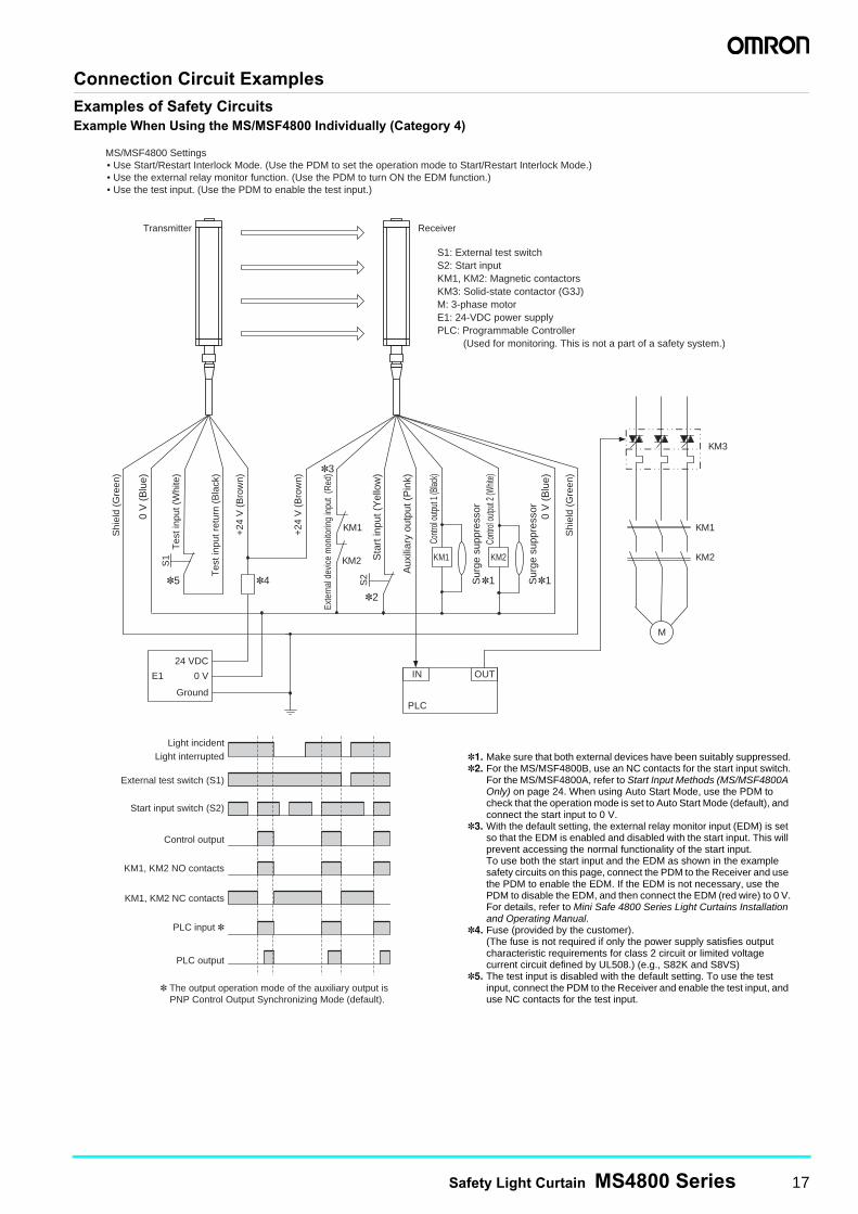
Connection Circuit ExamplesExamples of Safety CircuitsExample When Using the MS/MSF4800 Individually (Category 4)
0 V
(B
lue)
0 V
(B
lue)
Contr
ol ou
tput 1
(Blac
k)
Contr
ol ou
tput 2
(Whit
e)
Aux
iliar
y ou
tput
(P
ink)
Tes
t inp
ut r
etur
n (B
lack
)
Tes
t inp
ut (
Whi
te)
Transmitter Receiver
Shi
eld
(Gre
en)
Shi
eld
(Gre
en)
M
KM1
KM2 KM1 KM2
OUT
PLC
IN
Exte
rnal
dev
ice
mon
itorin
g in
put
(Red
)
Sta
rt in
put (
Yel
low
)
*1 *1
*3
*2
*4
0 V E1
Ground
Sur
ge s
uppr
esso
r
Sur
ge s
uppr
esso
r
S2
KM1
KM2
*5
S1
Control output
KM3
* The output operation mode of the auxiliary output is PNP Control Output Synchronizing Mode (default).
External test switch (S1)
Start input switch (S2)
Light interrupted Light incident
PLC output
PLC input *
KM1, KM2 NC contacts
KM1, KM2 NO contacts
+24
V (
Bro
wn)
+24
V (
Bro
wn)
24 VDC
MS/MSF4800 Settings • Use Start/Restart Interlock Mode. (Use the PDM to set the operation mode to Start/Restart Interlock Mode.) • Use the external relay monitor function. (Use the PDM to turn ON the EDM function.) • Use the test input. (Use the PDM to enable the test input.)
S1: External test switch S2: Start input KM1, KM2: Magnetic contactors KM3: Solid-state contactor (G3J) M: 3-phase motor E1: 24-VDC power supply PLC: Programmable Controller
(Used for monitoring. This is not a part of a safety system.)
*1. Make sure that both external devices have been suitably suppressed.*2. For the MS/MSF4800B, use an NC contacts for the start input switch.
For the MS/MSF4800A, refer to Start Input Methods (MS/MSF4800A Only) on page 24. When using Auto Start Mode, use the PDM to check that the operation mode is set to Auto Start Mode (default), and connect the start input to 0 V.
*3. With the default setting, the external relay monitor input (EDM) is set so that the EDM is enabled and disabled with the start input. This will prevent accessing the normal functionality of the start input. To use both the start input and the EDM as shown in the example safety circuits on this page, connect the PDM to the Receiver and use the PDM to enable the EDM. If the EDM is not necessary, use the PDM to disable the EDM, and then connect the EDM (red wire) to 0 V.For details, refer to Mini Safe 4800 Series Light Curtains Installation and Operating Manual.
*4. Fuse (provided by the customer).(The fuse is not required if only the power supply satisfies output characteristic requirements for class 2 circuit or limited voltage current circuit defined by UL508.) (e.g., S82K and S8VS)
*5. The test input is disabled with the default setting. To use the test input, connect the PDM to the Receiver and enable the test input, and use NC contacts for the test input.
18 Safety Light Curtain MS4800 Series
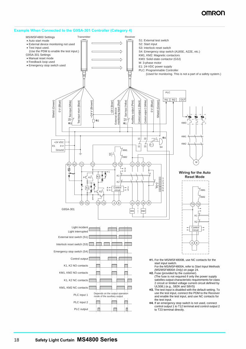
Example When Connected to the G9SA-301 Controller (Category 4)
M
OUT
PLC
KM1
KM2
IN1 IN2
KM3
A1
T23 PE 14 24 34 42
41 33 23 13 T32 T31 T11 A2
KM1 KM2 G9SA-301
KM1
KM2
T12
K1 K1
K2
K1
T21
S3
Transmitter Receiver
6
a K2
K2 b
Control circuit
T22 A B
a b
2 5
1 3 4
1 2 3 4 5 6
JP
11
12
21
22
S4
*3 S
2
*2 *1
*4
+24 VDC
0 V E1
Ground
MS/MSF4800 Settings • Auto start mode • External device monitoring not used • Test input used. (Use the PDM to enable the test input.)
G9SA-301 Settings • Manual reset mode • Feedback loop used • Emergency stop switch used
S 1
Depends on the output operation mode of the auxiliary output
S1: External test switch S2: Start input S3: Interlock reset switch S4: Emergency stop switch (A165E, A22E, etc.) KM1, KM2: Magnetic contactors KM3: Solid-state contactor (G3J) M: 3-phase motor E1: 24-VDC power supply PLC: Programmable Controller (Used for monitoring. This is not a part of a safety system.)
0 V
(B
lue)
0 V
(B
lue)
Cont
rol o
utpu
t 1 (B
lack
)
Cont
rol o
utpu
t 2 (W
hite
)
Aux
iliar
y ou
tput
(Pin
k)
Shi
eld
(Gre
en)
Shi
eld
(Gre
en)
Ext
erna
l dev
ice
mon
itorin
g in
put (
Red
)
Star
t inpu
t (Ye
llow)
+24
V (
Bro
wn)
+24
V (B
rown
)
Test
inpu
t (W
hite
)
Test
inpu
t ret
urn
(Bla
ck)
Control output
External test switch (S1)
Interlock reset switch (S3)
Light interrupted
Light incident
PLC output
PLC input 1
PLC input 2
KM1, KM2 NC contacts
K1, K2 NC contacts
KM1, KM2 NO contacts
K1, K2 NO contacts
Emergency stop switch (S4)
T32 T31
KM1
KM2
K1
K2
Control Circuit
A B
Wiring for the Auto Reset Mode
*1. For the MS/MSF4800B, use NC contacts for the start input switch.For the MS/MSF4800A, refer to Start Input Methods (MS/MSF4800A Only) on page 24.
*2. Fuse (provided by the customer).(The fuse is not required if only the power supply satisfies output characteristic requirements for class 2 circuit or limited voltage current circuit defined by UL508.) (e.g., S82K and S8VS)
*3. The test input is disabled with the default setting. To use the test input, connect the PDM to the Receiver and enable the test input, and use NC contacts for the test input.
*4. If an emergency stop switch is not used, connect control output 1 to T12 terminal and control output 2 to T23 terminal directly.
Safety Light Curtain MS4800 Series 19
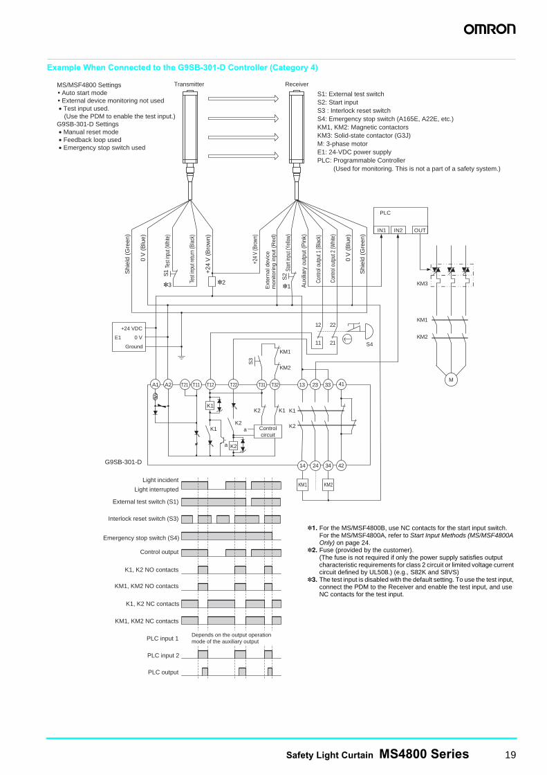
Example When Connected to the G9SB-301-D Controller (Category 4)
M
OUT
PLC
KM1
KM2
IN1 IN2
KM3
A1
14 24 34 42
41 33 23 13 T32 T31 A2
KM1 KM2
G9SB-301-D
KM1
KM2
T12
K1
K1 K2
S3
Transmitter Receiver
a K2
K2
T22
a
11
12
21
22
S4
K1
K2 Control circuit
T11 T21
K1
S2
*2 *1 *3
S 1
MS/MSF4800 Settings • Auto start mode • External device monitoring not used • Test input used. (Use the PDM to enable the test input.)
G9SB-301-D Settings • Manual reset mode • Feedback loop used • Emergency stop switch used
S1: External test switch S2: Start input S3 : Interlock reset switch S4: Emergency stop switch (A165E, A22E, etc.) KM1, KM2: Magnetic contactors KM3: Solid-state contactor (G3J) M: 3-phase motor E1: 24-VDC power supply PLC: Programmable Controller (Used for monitoring. This is not a part of a safety system.)
PLC input 2
K1, K2 NC contacts
Emergency stop switch (S4)
Depends on the output operation mode of the auxiliary output
E1
Ground
+24 VDC
0 V
0 V
(B
lue)
0 V
(B
lue)
Cont
rol o
utpu
t 1 (B
lack
)
Cont
rol o
utpu
t 2 (W
hite
)
Aux
iliar
y ou
tput
(Pin
k)
Shi
eld
(Gre
en)
Shi
eld
(Gre
en)
Ext
erna
l dev
ice
mon
itorin
g in
put (
Red
)
Star
t inpu
t (Ye
llow)
+24
V (
Bro
wn)
+24
V (B
rown
)
Test
input
(Whit
e)
Test
inpu
t ret
urn
(Bla
ck)
Control output
External test switch (S1)
Interlock reset switch (S3)
Light interrupted
Light incident
PLC output
PLC input 1
KM1, KM2 NC contacts
KM1, KM2 NO contacts
K1, K2 NO contacts
*1. For the MS/MSF4800B, use NC contacts for the start input switch.For the MS/MSF4800A, refer to Start Input Methods (MS/MSF4800A Only) on page 24.
*2. Fuse (provided by the customer).(The fuse is not required if only the power supply satisfies output characteristic requirements for class 2 circuit or limited voltage current circuit defined by UL508.) (e.g., S82K and S8VS)
*3. The test input is disabled with the default setting. To use the test input, connect the PDM to the Receiver and enable the test input, and use NC contacts for the test input.
20 Safety Light Curtain MS4800 Series
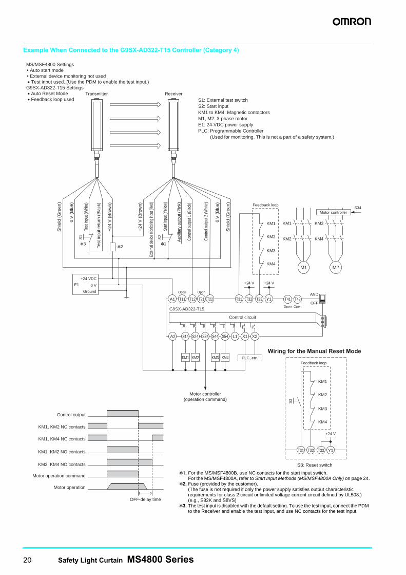
Example When Connected to the G9SX-AD322-T15 Controller (Category 4)
*1 *2
*3
A1
A2
T11
S14
T12
S24
T21
S34
T22
S44
T31
S54
T32
X1
T33
X2
Y1 T41 T42
G9SX-AD322-T15
Control circuit
L1
AND
OFF
PLC, etc.
Motor controller (operation command)
+24 V +24 V
Feedback loop
Open Open
KM3
KM4
KM1
KM2
Open Open
S2
S1
E1
Ground
KM3 KM4 KM2 KM1
Control output
KM1, KM2 NC contacts
KM1, KM4 NC contacts
KM1, KM2 NO contacts
KM3, KM4 NO contacts
Motor operation command
Motor operation
OFF-delay time
Transmitter Receiver
MS/MSF4800 Settings • Auto start mode • External device monitoring not used • Test input used. (Use the PDM to enable the test input.)
G9SX-AD322-T15 Settings • Auto Reset Mode • Feedback loop used S1: External test switch
S2: Start input KM1 to KM4: Magnetic contactors M1, M2: 3-phase motor E1: 24-VDC power supply PLC: Programmable Controller (Used for monitoring. This is not a part of a safety system.)
+24 VDC
0 V
0 V
(B
lue)
0 V
(B
lue)
Cont
rol o
utpu
t 1 (B
lack
)
Cont
rol o
utpu
t 2 (W
hite
)
Aux
iliar
y ou
tput
(Pin
k)
Shi
eld
(Gre
en)
Shi
eld
(Gre
en)
Exte
rnal
devic
e m
onito
ring
input
(Red
)
Star
t inp
ut (Y
ello
w)
+24
V (
Bro
wn)
+24
V (
Bro
wn)
Test
inpu
t (W
hite
)
Test
inpu
t ret
urn
(Bla
ck)
M1
KM1
KM2
KM3
KM4
M2
S34 Motor controller
Wiring for the Manual Reset Mode
S3: Reset switch
S3
Feedback loop
T31 T32 T33 Y1
+24 V
KM3
KM4
KM1
KM2
*1. For the MS/MSF4800B, use NC contacts for the start input switch.For the MS/MSF4800A, refer to Start Input Methods (MS/MSF4800A Only) on page 24.
*2. Fuse (provided by the customer).(The fuse is not required if only the power supply satisfies output characteristic requirements for class 2 circuit or limited voltage current circuit defined by UL508.) (e.g., S82K and S8VS)
*3. The test input is disabled with the default setting. To use the test input, connect the PDM to the Receiver and enable the test input, and use NC contacts for the test input.
Safety Light Curtain MS4800 Series 21
Connection to the MS4800-RM6 Resource Module (MSF4800A Only)
24 VDC 0 VEarth
ground
Start
MTS/Test
ED1 ED2
ED2
ED1
Suppressor
To machine control
ED1 ED2
OSSD 1
OSSD 2
Start
0 V
24 VDC
Auxiliaryoutput
Ground
EDM
MTS
0 V
24 VDC
Ground
MTSreturn
+VDC
−RS485
+RS485
Shield
Return
S-In 1
S-In 4
S-In 3
S-In 2
Lamp
Light operate
Dark operate
Dark operate
Muting inputsSensors with PNP outputs
Light operate
24 VDC
24 VDC
24 VDC
24 VDC
24 VDCM12 connector
Ground
MS4800-RM6 Resource Module
Orange
Power supply
MSF4800 Receiver
MSF4800 Transmitter
Blue
Blue
Blue
Red
Yellow
Pink
White
White
White
Brown
Brown
Brown
Green
Green
Black
Black*6
*6
*5
*1
*2
*9
*7
*10
*8*11
*3
*4
*1. When using relays with forcibly guided contacts as the final control devices, they must be monitored. Connect the red wire to 0 V via the NC contacts. (Do not use both external devices simultaneously.)
*2. The user can use the Programming and Diagnostics Module to turn OFF the external device monitoring (EDM) function for pre-installation testing. When doing this, the EDM wire (red wire) must be connected to 0 V.
*3. Auxiliary Output PNP: 100 mA max. (default)*4. Fuse (provided by the customer).*5. The start connection is shown with NC contacts (connected to 0 V).*6. Insert suppressors in parallel with the final control devices.*7. The MTS (test input) is disabled with the default setting. To use the test
input, connect the PDM to the Receiver and enable the test input, and use NC contacts for the test input.
*8. For details, refer to the Mini Safe 4800 Series Safety Light Curtains Installation and Operating Manual.
*9. Connect the yellow wire to 24 VDC to enable external device monitoring (EDM), and to 0 V to disable EDM.
*10.Not used.*11.There is no need to connect sensor inputs that are not used.
22 Safety Light Curtain MS4800 Series
Nomenclature
Individual Beam Indicators (IBI)
All MS4800 Safety Light Curtains have an Individual Beam Indicator (IBI) next to each infrared beam on the Receiver. The IBI indicates whether the beam is interrupted or clear. When the beam is interrupted, the IBI goes ON; when it is clear, the IBI goes OFF. If there is less than 10 clear beams, every other IBI will light to indicate that the MS/MSF4800 is not synchronized.
Example of IBI Indication for an Error (Error Code 34)
Note: For details on error codes, refer to the Mini Safe 4800 Series Safety Light Curtains Installation and Operating Manual.
Receiver LED Indicators
Transmitter LED Indicators
2
3 8
45
6
7
1 2
5
3 4
1
Detection zone
Receiver
Transmitter
Receiver
Machine Run/stop Indicator (Green/Red)Interlock or Alarm (Lockout) Indicator (Yellow)Blanking Active (Amber)
Transmitter
T-SLOT mounting example
Individual Beam Indicators (one per beam) (Red)
Programming Port for PDM
Receiver Connections M-12 (male 8-pin) Transmitter Connections M-12 (male 5-pin)
Programming Port for PDM
Transmitter LED IndicatorsReceiver LED Indicators
SealingCap (M8) Sealing
Cap (M8)
PDM Cable
Status Indicator (Yellow)
(1) 24 VDC (Brown)(2) 0 V (Blue)(3) Ground (Green)(4) Control output 2
(White)(5) Start or external
device monitoring (mode selection) (Yellow)
(6) External device monitoring (EDM) (Red)
(7) Auxiliary output (Pink)
(8) Control output 1 (Black)
(1) 0 V (Blue)(2) 24 VDC (Brown)(3) Test input (MTS) (White)(4) Test input (MTS) return
(Black)(5) Ground (Green)
Note: Remove the sealing cap (M8) to connect the PDM cable.
Front View of the Receiver
All IBIs starting with the ninth one from the end cap are OFF.
Four IBIs indicating the "ones digit" of the error code are ON.
Fourth IBI from the end cap is OFF.
Three IBIs indicating the "tens digit" of the error code are ON.
End cap
Error code: 3 4
Interlock indicator flashes.
This shows that control output 1 has been shorted to ground.
Operating condition
Conditionindication
Description
Machine Run State
Two Receiver control outputs (safety outputs) are ON, and the green Machine Run indicator is ON.
Machine Stop State
Two Receiver control outputs (safety outputs) are OFF, and the red Machine Stop indicator is ON.
Interlock State
Two Receiver control outputs (safety outputs) are OFF, and the red Machine Stop indicator and the yellow Interlock indicator are ON.
Alarm (Lockout) state
Two Receiver control outputs (safety outputs) are OFF, the red Machine Stop indicator is ON, the yellow Interlock indicator is flashing, and the auxiliary output is OFF.
Blanking Active state Operating with blanking enabled.
Operating condition
Conditionindication
Description
Transmitting state
When the Transmitter receives power and enters the Transmitting state, the indicator turns ON. When the Machine Test Signal (MTS) is enabled, the Transmitter enters the Transmitting Stop state, and the indicator turns OFF.
Error state/PDM Programming state
When an error occurs due to the Transmitter, or when the Programming and Diagnostics Module is being used to change a setting, the indicator flashes.
OFF Flashing ON
Green
Red
RedYellow
RedYellow
Amber
Flashing ON
Yellow
Yellow
Safety Light Curtain MS4800 Series 23
Safety FunctionsOperation ModesAuto Start
If no objects are detected in the sensing area when the power is turned ON in Auto Start Mode, the system enters the Machine Run State. If an object is then detected, the system changes from the Machine Run State to the Machine Stop State, and remains in that state until the object is removed. When the intrusion into the sensing area disappears, the system automatically changes from the Machine Stop State to the Machine Run State.
Start Interlock
If no objects are in the sensing area when the power is turned ON in Start Interlock Mode and an alarm (lockout) condition does not occur, the system enters the Interlock State. To shift to the Machine Run State, an operator must press and release the Start Button on the Safety Light Curtain. If an object intrudes in the sensing area during the Machine Run State, the system will change to the Machine Stop State. When the object is removed from the sensing area, the system will automatically shift to the Machine Run State.
Start/Restart Interlock
If no objects are in the sensing area when the power is turned ON in Start/Restart Interlock Mode and an alarm (lockout) condition does not occur, the system enters the Interlock State. To shift to the Machine Run State, an operator must press and release the Start Button on the Safety Light Curtain. If an object intrudes in the sensing area during the Machine Run State, the system will change to the Machine Stop State. When the object is removed from the sensing area, the system will shift to the Interlock State instead of automatically shifting to the Machine Run State. To shift to the Machine Run State, an operator must press and release the Start Button. When there is an object in the sensing area, the Start Button is disabled.
Blanking Functions (Advanced Series Only)Fixed Blanking
This function is used when a machine or workpiece constantly interrupts beams in a part of the sensing area. Fixed blanking allows the Safety Light Curtain to remain in the Machine Run State while the obstruction in the sensing area as a non-moving object. The output is turned OFF when a beam other than the set fixed blanking beams is interrupted, or when light is incident on a fixed blanking beam.
Floating Blanking
This function turns OFF the output when the total number of interrupted beams inside the sensing area exceeds the number of set beams (1 or 2).
Monitored Blanking
This function is used when a machine or workpiece constantly interrupts beams in a part of the sensing area and moves within the sensing area. Monitored blanking allows the Safety Light Curtain to remain in the Machine Run State while the obstruction moves within the sensing area. The output is turned OFF when the machine or workpiece disappears from the monitored blanking area that was set by teaching, or when the total number of interrupted beams increases due to a different obstruction.
Reduced Resolution Blanking
When the resolution of the MS/MSF4800A is reduced, the size of the minimum detectable object is increased. The output will not turn OFF regardless of how many continuous interrupted beams there are in the sensing area as long as the beams are fewer than the set number (1, 2, or 3 beams).When an object whose size exceeds the set number of beams intrudes, the output is turned OFF. For example, in an application where a conveyor cart approaches a robot work area, the Safety Light Curtain can be set so that it does not detect only the wheels of the cart, allowing the MS/MSF4800A to be used as a presence sensing device.
Muting Functions (MSF4800A Only)
Use of the MS4800-RM6 Resource Module (sold separately) makes it possible to temporarily disable the Safety Light Curtain. Select from among four muting modes to match each application with the appropriate number and placement of muting sensors.Note: For details on blanking and muting, refer to the Mini Safe 4800 Series
Safety Light Curtains Installation and Operating Manual.
Diagnostic FunctionsExternal Device Monitoring (EDM) (MPCE Monitoring)
This function detects malfunctions, such as welded contacts in external relays (or contactors) that control the hazardous area of a machine. This function constantly monitors that a specified voltage is applied to the Receiver's external device monitoring input line, and enters LOCKOUT state when an error occurs. The relay's operational delay can be up to 300 ms without being evaluated as an error.To utilize this function properly, use relays and contactors that have a forcibly guided contact structure.
Enabling/Disabling External Device MonitoringThe external device monitoring can be enabled or disabled
with the Programming and Diagnostics Module. When using the Auto Start Mode, enabling and disabling can be switched by combining the start input line with the external device monitoring wiring.Note: For details, refer to the Mini Safe 4800 Series Safety Light Curtains
Installation and Operating Manual.
Machine Test Signal (MTS)
The Machine Test Signal (MTS) is used to confirm that the safety system stops correctly when an MS/MSF4800 beam is interrupted by purposely halting the emission with an external signal. MTS is provided by placing a normally closed switch across the MTS and MTS Return lines of the Transmitter. A close-to-open transition on this switch will enable the MTS and halt the emission.
24 Safety Light Curtain MS4800 Series
Other FunctionsSensing Distance Selection
The Programming and Diagnostics Module can be used to select the sensing distance. The Short Range Mode is 8 m, and the Long Range Mode is 20 m (default). This function is useful when there are many Safety Light Curtains operating within a small space and the possibility of mutual interference is likely.
Response Time Adjustment (MS/MSF4800A Only)
The MS4800 allows the user to slow down the scan rate of the Safety Light Curtain for maximum immunity against environmental interference. This function may be used in harsh environmental conditions where electrical noise, ambient smoke, or dust and flying debris interfere with the Safety Light Curtain. For details, refer to Response Time on page 15.
Recalculate the safety distance whenever the responsetime has been changed.
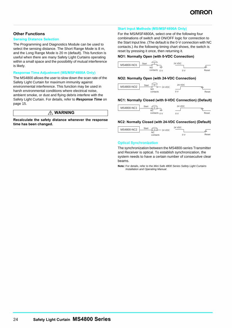
Start Input Methods (MS/MSF4800A Only)
For the MS/MSF4800A, select one of the following four combinations of switch and ON/OFF logic for connection to the Start Input line. (The default is the 0-V connection with NC contacts.) As the following timing chart shows, the switch is reset by pressing it once, then returning it.
NO1: Normally Open (with 0-VDC Connection)
NO2: Normally Open (with 24-VDC Connection)
NC1: Normally Closed (with 0-VDC Connection) (Default)
NC2: Normally Closed (with 24-VDC Connection) (Default)
Optical Synchronization
The synchronization between the MS4800-series Transmitter and Receiver is optical. To establish synchronization, the system needs to have a certain number of consecutive clear beams.Note: For details, refer to the Mini Safe 4800 Series Safety Light Curtains
Installation and Operating Manual.
WARNING
24 VDC
0 V ResetNO contacts 0 V
MS4800-NO1 Start
MS4800-NO2NO contacts 0 V
24 VDC24 VDC
Reset
Start
NC contacts 0 V0 V
MS4800-NC124 VDC
Reset
Start
NC contacts 0 V
MS4800-NC2 24 VDC24 VDC
Reset
Start
Safety Light Curtain MS4800 Series 25
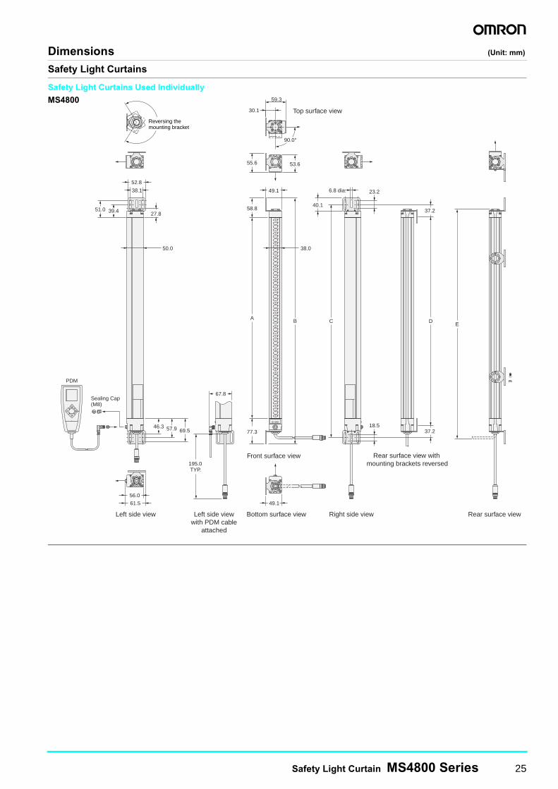
Dimensions (Unit: mm)
Safety Light Curtains
PDM
Sealing Cap(M8)
30.1
59.3
90.0°
53.655.6
40.1
6.8 dia. 23.238.1
27.8
49.1
58.8
38.050.0
39.451.0
52.8
46.3 57.9 69.5
56.0
61.5
195.0 TYP.
77.3
A B C D E
67.8
18.537.2
37.2
49.1
Rear surface view
Rear surface view with mounting brackets reversed
Right side view
Top surface view
Left side view Left side viewwith PDM cable
attached
Bottom surface view
Front surface view
Reversing the mounting bracket
Safety Light Curtains Used Individually
MS4800
26 Safety Light Curtain MS4800 Series
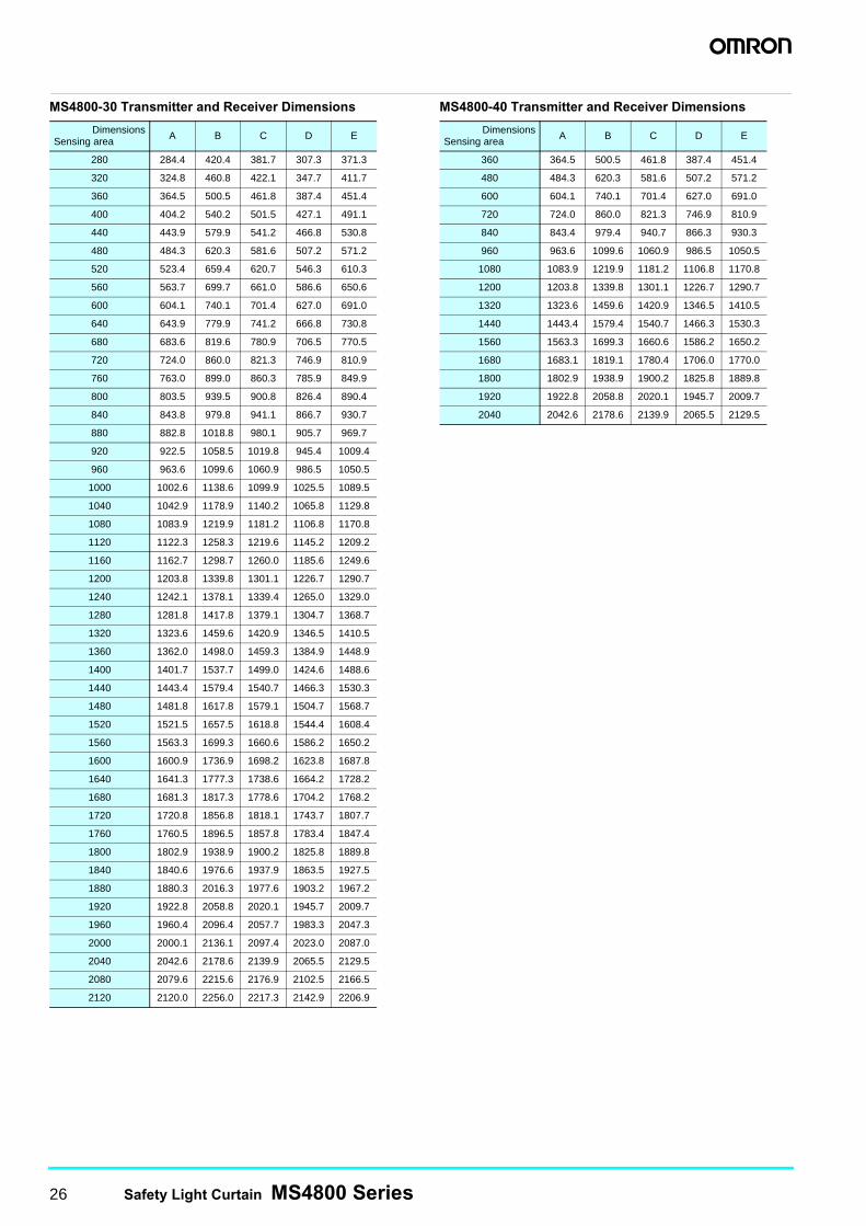
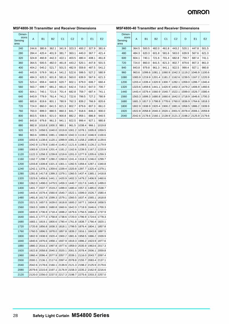
MS4800-30 Transmitter and Receiver Dimensions MS4800-40 Transmitter and Receiver Dimensions
DimensionsSensing area A B C D E
280 284.4 420.4 381.7 307.3 371.3
320 324.8 460.8 422.1 347.7 411.7
360 364.5 500.5 461.8 387.4 451.4
400 404.2 540.2 501.5 427.1 491.1
440 443.9 579.9 541.2 466.8 530.8
480 484.3 620.3 581.6 507.2 571.2
520 523.4 659.4 620.7 546.3 610.3
560 563.7 699.7 661.0 586.6 650.6
600 604.1 740.1 701.4 627.0 691.0
640 643.9 779.9 741.2 666.8 730.8
680 683.6 819.6 780.9 706.5 770.5
720 724.0 860.0 821.3 746.9 810.9
760 763.0 899.0 860.3 785.9 849.9
800 803.5 939.5 900.8 826.4 890.4
840 843.8 979.8 941.1 866.7 930.7
880 882.8 1018.8 980.1 905.7 969.7
920 922.5 1058.5 1019.8 945.4 1009.4
960 963.6 1099.6 1060.9 986.5 1050.5
1000 1002.6 1138.6 1099.9 1025.5 1089.5
1040 1042.9 1178.9 1140.2 1065.8 1129.8
1080 1083.9 1219.9 1181.2 1106.8 1170.8
1120 1122.3 1258.3 1219.6 1145.2 1209.2
1160 1162.7 1298.7 1260.0 1185.6 1249.6
1200 1203.8 1339.8 1301.1 1226.7 1290.7
1240 1242.1 1378.1 1339.4 1265.0 1329.0
1280 1281.8 1417.8 1379.1 1304.7 1368.7
1320 1323.6 1459.6 1420.9 1346.5 1410.5
1360 1362.0 1498.0 1459.3 1384.9 1448.9
1400 1401.7 1537.7 1499.0 1424.6 1488.6
1440 1443.4 1579.4 1540.7 1466.3 1530.3
1480 1481.8 1617.8 1579.1 1504.7 1568.7
1520 1521.5 1657.5 1618.8 1544.4 1608.4
1560 1563.3 1699.3 1660.6 1586.2 1650.2
1600 1600.9 1736.9 1698.2 1623.8 1687.8
1640 1641.3 1777.3 1738.6 1664.2 1728.2
1680 1681.3 1817.3 1778.6 1704.2 1768.2
1720 1720.8 1856.8 1818.1 1743.7 1807.7
1760 1760.5 1896.5 1857.8 1783.4 1847.4
1800 1802.9 1938.9 1900.2 1825.8 1889.8
1840 1840.6 1976.6 1937.9 1863.5 1927.5
1880 1880.3 2016.3 1977.6 1903.2 1967.2
1920 1922.8 2058.8 2020.1 1945.7 2009.7
1960 1960.4 2096.4 2057.7 1983.3 2047.3
2000 2000.1 2136.1 2097.4 2023.0 2087.0
2040 2042.6 2178.6 2139.9 2065.5 2129.5
2080 2079.6 2215.6 2176.9 2102.5 2166.5
2120 2120.0 2256.0 2217.3 2142.9 2206.9
DimensionsSensing area A B C D E
360 364.5 500.5 461.8 387.4 451.4
480 484.3 620.3 581.6 507.2 571.2
600 604.1 740.1 701.4 627.0 691.0
720 724.0 860.0 821.3 746.9 810.9
840 843.4 979.4 940.7 866.3 930.3
960 963.6 1099.6 1060.9 986.5 1050.5
1080 1083.9 1219.9 1181.2 1106.8 1170.8
1200 1203.8 1339.8 1301.1 1226.7 1290.7
1320 1323.6 1459.6 1420.9 1346.5 1410.5
1440 1443.4 1579.4 1540.7 1466.3 1530.3
1560 1563.3 1699.3 1660.6 1586.2 1650.2
1680 1683.1 1819.1 1780.4 1706.0 1770.0
1800 1802.9 1938.9 1900.2 1825.8 1889.8
1920 1922.8 2058.8 2020.1 1945.7 2009.7
2040 2042.6 2178.6 2139.9 2065.5 2129.5
Safety Light Curtain MS4800 Series 27
46.3 57.9 69.5
C2
C1
E2
E1
D
37.2
37.2
77.3
B1A
A
58.8
58.8
58.8
49.1
B2
113.0TYP.
49.1
Bottom surface view
Front surface view195.0 TYP.
67.8
Left side viewwith PDM cable
attached
PDM
Sealing Cap(M8)
55.6
50.0
38.1
27.839.451.0
27.839.451.0
27.839.451.0
55.6
Reversing the mounting bracket
38.0
40.1
6.8 dia. 23.2
18.5
30.1
59.3
90.0°
50.0
Top surface view
Rear surface view
Rear surface view with mounting bracket reversed
Right side view
Sealing Cap(M12)
56.0
61.5
Left side view
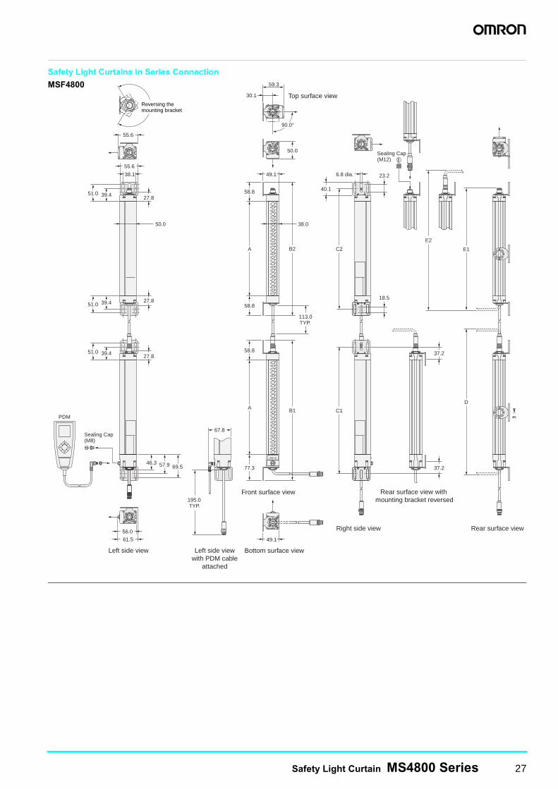
Safety Light Curtains in Series Connection
MSF4800
28 Safety Light Curtain MS4800 Series
MSF4800-30 Transmitter and Receiver Dimensions MSF4800-40 Transmitter and Receiver Dimensions
Dimen-sions
Sensingarea
A B1 B2 C1 C2 D E1 E2
240 244.6 380.6 362.1 341.9 323.3 400.2 327.9 381.6
280 284.4 420.4 401.9 381.7 363.1 440.0 367.7 421.4
320 324.8 460.8 442.3 422.1 403.5 480.4 408.1 461.8
360 364.5 500.5 482.0 461.8 443.2 520.1 447.8 501.5
400 404.2 540.2 521.7 501.5 482.9 559.8 487.5 541.2
440 443.9 579.9 561.4 541.2 522.6 599.5 527.2 580.9
480 484.3 620.3 601.8 581.6 563.0 639.9 567.6 621.3
520 523.4 659.4 640.9 620.7 602.1 679.0 606.7 660.4
560 563.7 699.7 681.2 661.0 642.4 719.3 647.0 700.7
600 604.1 740.1 721.6 701.4 682.8 759.7 687.4 741.1
640 643.9 779.9 761.4 741.2 722.6 799.5 727.2 780.9
680 683.6 819.6 801.1 780.9 762.3 839.2 766.9 820.6
720 724.0 860.0 841.5 821.3 802.7 879.6 807.3 861.0
760 763.0 899.0 880.5 860.3 841.7 918.6 846.3 900.0
800 803.5 939.5 921.0 900.8 882.2 959.1 886.8 940.5
840 843.8 979.8 961.3 941.1 922.5 999.4 927.1 980.8
880 882.8 1018.8 1000.3 980.1 961.5 1038.4 966.1 1019.8
920 922.5 1058.5 1040.0 1019.8 1001.2 1078.1 1005.8 1059.5
960 963.6 1099.6 1081.1 1060.9 1042.3 1119.2 1046.9 1100.6
1000 1002.6 1138.6 1120.1 1099.9 1081.3 1158.2 1085.9 1139.6
1040 1042.9 1178.9 1160.4 1140.2 1121.6 1198.5 1126.2 1179.9
1080 1083.9 1219.9 1201.4 1181.2 1162.6 1239.5 1167.2 1220.9
1120 1122.3 1258.3 1239.8 1219.6 1201.0 1277.9 1205.6 1259.3
1160 1162.7 1298.7 1280.2 1260.0 1241.4 1318.3 1246.0 1299.7
1200 1203.8 1339.8 1321.3 1301.1 1282.5 1359.4 1287.1 1340.8
1240 1242.1 1378.1 1359.6 1339.4 1320.8 1397.7 1325.4 1379.1
1280 1281.8 1417.8 1399.3 1379.1 1360.5 1437.4 1365.1 1418.8
1320 1323.6 1459.6 1441.1 1420.9 1402.3 1479.2 1406.9 1460.6
1360 1362.0 1498.0 1479.5 1459.3 1440.7 1517.6 1445.3 1499.0
1400 1401.7 1537.7 1519.2 1499.0 1480.4 1557.3 1485.0 1538.7
1440 1443.4 1579.4 1560.9 1540.7 1522.1 1599.0 1526.7 1580.4
1480 1481.8 1617.8 1599.3 1579.1 1560.5 1637.4 1565.1 1618.8
1520 1521.5 1657.5 1639.0 1618.8 1600.2 1677.1 1604.8 1658.5
1560 1563.3 1699.3 1680.8 1660.6 1642.0 1718.9 1646.6 1700.3
1600 1600.9 1736.9 1718.4 1698.2 1679.6 1756.5 1684.2 1737.9
1640 1641.3 1777.3 1758.8 1738.6 1720.0 1796.9 1724.6 1778.3
1680 1683.1 1819.1 1800.6 1780.4 1761.8 1838.7 1766.4 1820.1
1720 1720.8 1856.8 1838.3 1818.1 1799.5 1876.4 1804.1 1857.8
1760 1760.5 1896.5 1878.0 1857.8 1839.2 1916.1 1843.8 1897.5
1800 1802.9 1938.9 1920.4 1900.2 1881.6 1958.5 1886.2 1939.9
1840 1840.6 1976.6 1958.1 1937.9 1919.3 1996.2 1923.9 1977.6
1880 1880.3 2016.3 1997.8 1977.6 1959.0 2035.9 1963.6 2017.3
1920 1922.8 2058.8 2040.3 2020.1 2001.5 2078.4 2006.1 2059.8
1960 1960.4 2096.4 2077.9 2057.7 2039.1 2116.0 2043.7 2097.4
2000 2000.1 2136.1 2117.6 2097.4 2078.8 2155.7 2083.4 2137.1
2040 2042.6 2178.6 2160.1 2139.9 2121.3 2198.2 2125.9 2179.6
2080 2079.6 2215.6 2197.1 2176.9 2158.3 2235.2 2162.9 2216.6
2120 2120.0 2256.0 2237.5 2217.3 2198.7 2275.6 2203.3 2257.0
Dimen-sions
Sensingarea
A B1 B2 C1 C2 D E1 E2
360 364.5 500.5 482.0 461.8 443.2 520.1 447.8 501.5
480 484.3 620.3 601.8 581.6 563.0 639.9 567.6 621.3
600 604.1 740.1 721.6 701.4 682.8 759.7 687.4 741.1
720 724.0 860.0 841.5 821.3 802.7 879.6 807.3 861.0
840 843.8 979.8 961.3 941.1 922.5 999.4 927.1 980.8
960 963.6 1099.6 1081.1 1060.9 1042.3 1119.2 1046.9 1100.6
1080 1083.9 1219.9 1201.4 1181.2 1162.6 1239.5 1167.2 1220.9
1200 1203.4 1339.4 1320.9 1300.7 1282.1 1359.0 1286.7 1340.4
1320 1323.6 1459.6 1441.1 1420.9 1402.3 1479.2 1406.9 1460.6
1440 1443.4 1579.4 1560.9 1540.7 1522.1 1599.0 1526.7 1580.4
1560 1563.3 1699.3 1680.8 1660.6 1642.0 1718.9 1646.6 1700.3
1680 1681.3 1817.3 1798.8 1778.6 1760.0 1836.9 1764.6 1818.3
1800 1802.9 1938.9 1920.4 1900.2 1881.6 1958.5 1886.2 1939.9
1920 1922.8 2058.8 2040.3 2020.1 2001.5 2078.4 2006.1 2059.8
2040 2042.6 2178.6 2160.1 2139.9 2121.3 2198.2 2125.9 2179.6
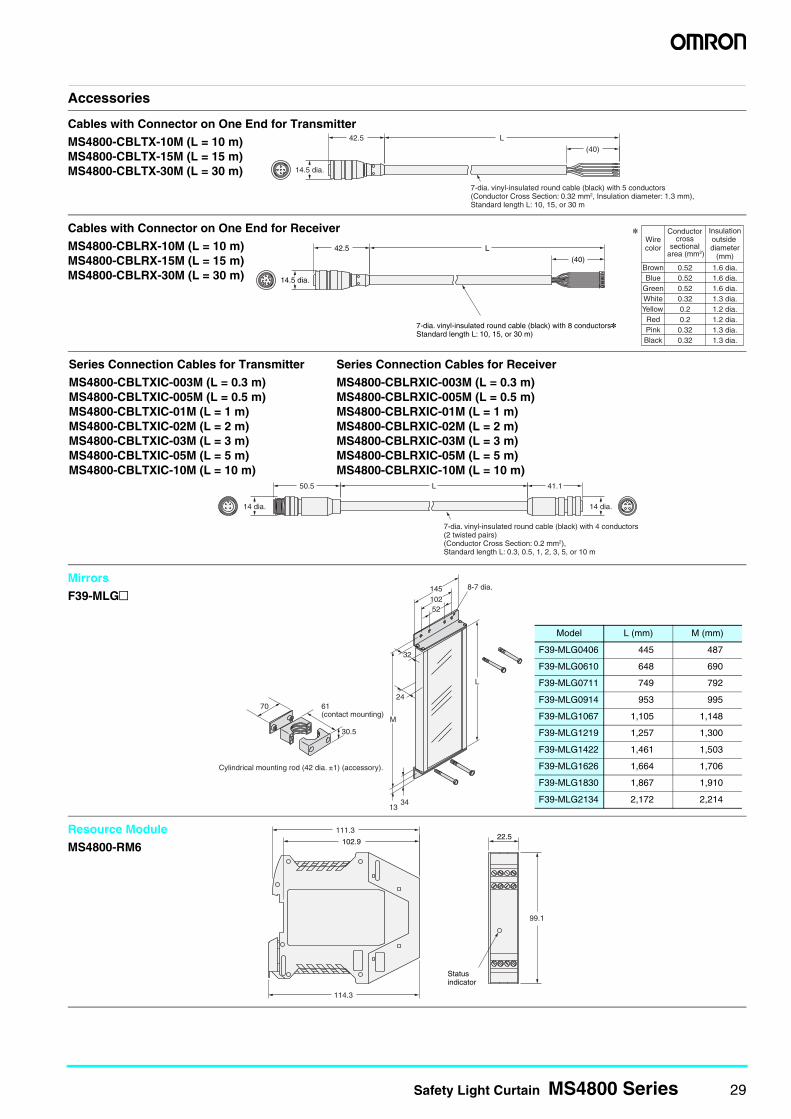
Safety Light Curtain MS4800 Series 29
Accessories
7-dia. vinyl-insulated round cable (black) with 5 conductors(Conductor Cross Section: 0.32 mm2, Insulation diameter: 1.3 mm),Standard length L: 10, 15, or 30 m
42.5
14.5 dia.
(40)
L
Cables with Connector on One End for Transmitter
MS4800-CBLTX-10M (L = 10 m)MS4800-CBLTX-15M (L = 15 m)MS4800-CBLTX-30M (L = 30 m)
42.5
14.5 dia.
(40)
LWirecolor
* Conductor cross
sectional area (mm2)
Insulationoutside diameter
(mm)
BrownBlue
GreenWhiteYellowRedPinkBlack
0.520.520.520.320.20.20.320.32
1.6 dia.1.6 dia.1.6 dia.1.3 dia.1.2 dia.1.2 dia.1.3 dia.1.3 dia.
7-dia. vinyl-insulated round cable (black) with 8 conductors*Standard length L: 10, 15, or 30 m)
Cables with Connector on One End for Receiver
MS4800-CBLRX-10M (L = 10 m)MS4800-CBLRX-15M (L = 15 m)MS4800-CBLRX-30M (L = 30 m)
14 dia. 14 dia.
50.5 41.1 L
7-dia. vinyl-insulated round cable (black) with 4 conductors(2 twisted pairs)(Conductor Cross Section: 0.2 mm2),Standard length L: 0.3, 0.5, 1, 2, 3, 5, or 10 m
Series Connection Cables for Transmitter
MS4800-CBLTXIC-003M (L = 0.3 m)MS4800-CBLTXIC-005M (L = 0.5 m)MS4800-CBLTXIC-01M (L = 1 m)MS4800-CBLTXIC-02M (L = 2 m)MS4800-CBLTXIC-03M (L = 3 m)MS4800-CBLTXIC-05M (L = 5 m)MS4800-CBLTXIC-10M (L = 10 m)
Series Connection Cables for Receiver
MS4800-CBLRXIC-003M (L = 0.3 m)MS4800-CBLRXIC-005M (L = 0.5 m)MS4800-CBLRXIC-01M (L = 1 m)MS4800-CBLRXIC-02M (L = 2 m)MS4800-CBLRXIC-03M (L = 3 m)MS4800-CBLRXIC-05M (L = 5 m)MS4800-CBLRXIC-10M (L = 10 m)
8-7 dia.
52
L
70
30.5
Cylindrical mounting rod (42 dia. ±1) (accessory).
61 (contact mounting)
32
24
M
3413
102145
Mirrors
F39-MLG@
Model L (mm) M (mm)
F39-MLG0406 445 487
F39-MLG0610 648 690
F39-MLG0711 749 792
F39-MLG0914 953 995
F39-MLG1067 1,105 1,148
F39-MLG1219 1,257 1,300
F39-MLG1422 1,461 1,503
F39-MLG1626 1,664 1,706
F39-MLG1830 1,867 1,910
F39-MLG2134 2,172 2,214
102.9
Statusindicator
22.5
114.3
99.1
111.3Resource Module
MS4800-RM6
30 Safety Light Curtain MS4800 Series
Safety PrecautionsThis document is intended as a guide for product selection. Be sure to read the Instruction Manual provided with the product for actual operation.
Regulations and Standards
1. Application of an MS/MSF4800-series Safety Light Curtain alone cannot receive type certification provided by Article 44-2 of the Industrial Safety and Health Law of Japan. It is necessary to apply the Curtain in a system. Therefore, when using the MS/MSF4800-series Safety Light Curtain in Japan as a “safety device for presses or shearing machines” prescribed in Article 42 of that law, the system must receive type certification.
2. The MS/MSF4800-series Safety Light Curtain is electro-sensitive protective equipment (ESPE) in accordance with European Union (EU) Machinery Directive Index Annex IV, B, Safety Components, Item 1.
3. The MS/MSF4800-series Safety Light Curtain complies with the following legislation and standards:(1) EU Regulations
Machinery Directive: Directive 2006/42/ECEMC Directive: Directive 2004/108/EC
(2) European standards:EN 61496-1 (TYPE 4 ESPE)CLC/TS61496-2 (TYPE 4 AOPD)EN 61508-1 to -7 (SIL3)EN ISO 13849-1: 2008 (Category 4/PLe)EN 62061, EN 50178, EN60204-1
(3) International standards:IEC 61496-1 (TYPE 4 ESPE)IEC 61496-2 (TYPE 4 AOPD)EN 61508-1 to -7 (SIL3)
(4) JIS standards:JIS B9704-1 (TYPE 4 ESPE)JIS B9704-2 (TYPE 4 AOPD)
(5) North American standards:UL 61496-1 (Type 4 ESPE)UL 61496-2 (Type 4 AOPD)UL 508, UL 1998, CAN/CSA 22.2 No. 14CAN/CSA 22.2 No. 0.8
4. The MS/MSF4800 received the following certification from TÜV Rheinland, an EU-accredited body:• EC type test based on Machinery Directive
Type 4 ESPE (IEC 61496-1)Type 4 AOPD (IEC 61496-2)
• TÜV Rheinland type certificationType 4 ESPE (IEC 61496-1)Type 4 AOPD (IEC 61496-2)
• SIL3 (IEC 61508)Category 4/PLe (EN ISO 139849-1: 2008)
5. The MS/MSF4800 has received certificates for UL listing for US and Canadian safety standards from UL, a third party assessment body.• Type 4 ESPE (UL 61496-1)
Type 4 AOPD (UL 61496-2)
6. The MS/MSF4800 is designed according to the standards listed below. To make sure that the final system complies with the following standards and regulations, you are asked to design and use it in accordance with all other related standards, laws, and regulations.If you have any questions, consult with UL or other specialized organizations.• European standards: EN 415-4, EN 692, EN 693• US Occupational Safety and Health Administration:
OSHA 29 CFR 1910.212• US Occupational Safety and Health Administration:
OSHA 29 CFR 1910.217• American National Standard Institute: ANSI B11.1 to
B11.19• American National Standard Institute: ANSI/RIA 15.06• Canadian Standards Association: CSA Z142, Z432,
Z434• SEMI standard SEMI S2
Safety Light Curtain MS4800 Series 31
Precautions for Safe UseIndications and Meanings for Safe Use
To ensure safe use of the MS/MSF4800, signal words and an alert symbol are used in this document to indicate safety-related instructions. These instructions describe details very important to your safety. It is extremely important that you understand and follow the instructions. The signal words and alert symbol used in this document are shown below.
Meaning of Symbol
Warning Indications
The MS/MSF4800 is a safety area sensor that is designed to protect operators who work in hazardous environments, such as those containing operating machinery.
MS/MSF4800 safety levels for specific applications and installation conditions can be attained only by achieving safe usage, installation, maintenance, and operation of the MS/MSF4800. These factors must be thoroughly confirmed by the customer who purchased the MS/MSF4800, as well as installers and employers.
Precautions for Users
The MS/MSF4800 must be installed, set, and integrated into the mechanical control system by a qualified technician who has received the appropriate training. Installation by an unqualified person may prevent the MS/MSF4800 from operating correctly, with the result that people may go undetected, and serious injuries may occur.
When changing parameters with the Programming and Diagnostics Module, the change must be made and the contents of the change must be managed by the person in charge of the system. Unintentional or mistaken parameter changes may prevent detection of people and result in serious injury.
The manager of the system is responsible for the selection and training of personnel to properly install, operate, and maintain the machine and its safeguarding systems.
The MS/MSF4800 must be installed, verified, and maintained by a qualified person. A qualified person is defined as someone who holds credentials or certification proving that he or she has received relevant
professional training, or someone whose ability to solve problems related to the specific matters or operations at hand has been verified by considerable knowledge, training or considerable experience. (See ANSI/PMMI B155.1-2006 for details.)
Machine Installation
Do not use this sensor for machines that cannot possibly be quickly stopped by electrical controls. For example, do not use it for a pressing machine that uses a full-rotation clutch. Otherwise, the machine may not stop before a person reaches the hazardous part, resulting in serious injury.
Do not use the auxiliary output for safety applications. Failure of the MS/MSF4800 may cause a person to go undetected, resulting in serious injury.
The guarded machine must not present a hazard from flying parts.
The guarded machine must have a consistent stopping time and adequate control mechanisms.
All safety-related machine control elements must be designed so that a failure in the control logic or a failure in the control circuit does not lead to danger.
Additional guarding may be required for access to dangerous areas not covered by the MS/MSF4800 system.
For Mounting
Be sure to test the operation of the MS/MSF4800 after installation with the machine in a non-operating condition to verify that the MS/MSF4800 operates as intended. Unintended function settings may cause a person to go undetected, resulting in serious injury.
Be sure to secure the safety distance between the MS/MSF4800 and the hazardous parts. Otherwise, the machine may not stop before a person reaches the hazardous part, resulting in serious injury.
Install a protective structure so that the hazardous part of a machine can only be reached by passing through the sensor's detection zone. Install the sensors so that part of the person is always present in the detection zone when working in a machine's hazardous areas. If a person is able to step into the hazardous area of a machine and remain behind the MS/MSF4800's detection zone, configure the system with an interlock function that prevents the machine from being restarted. Otherwise it may result in heavy injury.
When using Start/Restart Interlock Mode, install the interlock reset switch in a location that provides a clear view of the entire hazardous area and where it cannot be activated from within the hazardous area.
Indicates a potentially hazardous situation which, if not avoided, will result in minor or moderate injury, or may result in serious injury or death. Additionally, there may by significant property damage.
General ProhibitionIndicates a general prohibition
WARNING
WARNING
WARNING
WARNING
WARNING
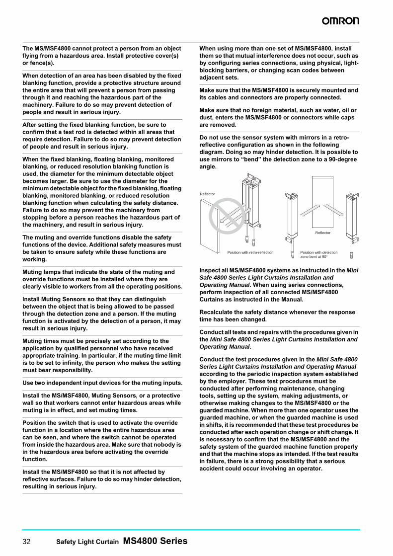
32 Safety Light Curtain MS4800 Series
The MS/MSF4800 cannot protect a person from an object flying from a hazardous area. Install protective cover(s) or fence(s).
When detection of an area has been disabled by the fixed blanking function, provide a protective structure around the entire area that will prevent a person from passing through it and reaching the hazardous part of the machinery. Failure to do so may prevent detection of people and result in serious injury.
After setting the fixed blanking function, be sure to confirm that a test rod is detected within all areas that require detection. Failure to do so may prevent detection of people and result in serious injury.
When the fixed blanking, floating blanking, monitored blanking, or reduced resolution blanking function is used, the diameter for the minimum detectable object becomes larger. Be sure to use the diameter for the minimum detectable object for the fixed blanking, floating blanking, monitored blanking, or reduced resolution blanking function when calculating the safety distance. Failure to do so may prevent the machinery from stopping before a person reaches the hazardous part of the machinery, and result in serious injury.
The muting and override functions disable the safety functions of the device. Additional safety measures must be taken to ensure safety while these functions are working.
Muting lamps that indicate the state of the muting and override functions must be installed where they are clearly visible to workers from all the operating positions.
Install Muting Sensors so that they can distinguish between the object that is being allowed to be passed through the detection zone and a person. If the muting function is activated by the detection of a person, it may result in serious injury.
Muting times must be precisely set according to the application by qualified personnel who have received appropriate training. In particular, if the muting time limit is to be set to infinity, the person who makes the setting must bear responsibility.
Use two independent input devices for the muting inputs.
Install the MS/MSF4800, Muting Sensors, or a protective wall so that workers cannot enter hazardous areas while muting is in effect, and set muting times.
Position the switch that is used to activate the override function in a location where the entire hazardous area can be seen, and where the switch cannot be operated from inside the hazardous area. Make sure that nobody is in the hazardous area before activating the override function.
Install the MS/MSF4800 so that it is not affected by reflective surfaces. Failure to do so may hinder detection, resulting in serious injury.
When using more than one set of MS/MSF4800, install them so that mutual interference does not occur, such as by configuring series connections, using physical, light-blocking barriers, or changing scan codes between adjacent sets.
Make sure that the MS/MSF4800 is securely mounted and its cables and connectors are properly connected.
Make sure that no foreign material, such as water, oil or dust, enters the MS/MSF4800 or connectors while caps are removed.
Do not use the sensor system with mirrors in a retro-reflective configuration as shown in the following diagram. Doing so may hinder detection. It is possible to use mirrors to “bend” the detection zone to a 90-degree angle.
Inspect all MS/MSF4800 systems as instructed in the Mini Safe 4800 Series Light Curtains Installation and Operating Manual. When using series connections, perform inspection of all connected MS/MSF4800 Curtains as instructed in the Manual.
Recalculate the safety distance whenever the response time has been changed.
Conduct all tests and repairs with the procedures given in the Mini Safe 4800 Series Light Curtains Installation and Operating Manual.
Conduct the test procedures given in the Mini Safe 4800 Series Light Curtains Installation and Operating Manual according to the periodic inspection system established by the employer. These test procedures must be conducted after performing maintenance, changing tools, setting up the system, making adjustments, or otherwise making changes to the MS/MSF4800 or the guarded machine. When more than one operator uses the guarded machine, or when the guarded machine is used in shifts, it is recommended that these test procedures be conducted after each operation change or shift change. It is necessary to confirm that the MS/MSF4800 and the safety system of the guarded machine function properly and that the machine stops as intended. If the test results in failure, there is a strong possibility that a serious accident could occur involving an operator.
Reflector
Position with retro-reflection Position with detection zone bent at 90°
Reflector
Safety Light Curtain MS4800 Series 33
Wiring Precautions
For an PNP output, connect the load between the output and 0 V line. Connecting the load between the output and +24 V line results in a dangerous condition because the operation mode is reversed to “ON when light is interrupted.”
Do not interconnect an output line with the +24-V line. Otherwise, the output is always ON, creating a dangerous situation. Also, 0 V of the power supply must be grounded so that output does not turn ON due to grounding of the output line.
Configure the system by using the optimal number of control outputs that satisfy the requirements of the necessary safety category.
Do not connect the lines of the MS/MSF4800 to a DC power supply higher than 24 VDC +20%. Also, do not connect to an AC power supply. Otherwise, it may result in electric shock.
For the MS/MSF4800 to comply with IEC 61496-1 and UL 508, the DC power supply unit must satisfy all of the following conditions:• Must be within rated power voltage (24 VDC ±20%).• Must have tolerance against the total rated current of
devices if it is connected to multiple devices.• Must comply with EMC directives (industrial
environment).• Double or enhanced insulation must be applied
between the primary and secondary circuits.• Automatic recovery must be possible for overcurrent
protection.• Output holding time must be 20 ms or longer.• Must satisfy output characteristic requirements for
class 2 circuit or limited voltage current circuit defined by UL508.
• Must comply with the EMC, laws, and regulations of the country or region where the MS/MSF4800 is used. (For example, in the EU, the power supply must comply with the EMC Low Voltage Directive.)
Double or enhanced insulation from hazardous voltage must be applied to all input and output lines. Failure to do so may result in electric shock.
The cable extension length must be no greater than the specified length. Otherwise, the safety functions may fail to work properly, resulting in danger.
Other Precautions
To use the MS/MSF4800 in PSDI Mode (i.e., restarting cycle operation by the sensor), you must configure an appropriate control circuit between the MS/MSF4800 and the machine. For details about PSDI, refer to ANSI RIA 15.06-1999, OSHA 1910.217 (h), ANSI B11.2-1995 (R2005), and other relevant standards and regulations.
Do not try to disassemble, repair, or modify this product. Doing so may cause the safety functions to stop working properly.
Do not use the MS/MSF4800 in environments where flammable or explosive gases are present. Doing so may result in explosion.
Perform daily and 6-month inspections for the MS/MSF4800. Otherwise, the system may fail to work properly, resulting in serious injury.
Safety Distance
Be sure to secure the safety distance between the MS/MSF4800 and the hazardous part. Otherwise, the machine may not stop before a person reaches the hazardous part, resulting in serious injury.
Note: The response time of a machine is the time period from when the machine receives a stop signal to when the machine's hazardous part stops. Measure the response time on the actual system. Also, periodically check that the response time of the machine has not changed.
How to Calculate the Safety Distance Specified by International Standard ISO 13855-2002 (European Standard EN 999-1999) (Reference)The following explanation is based on standard EN 999. This standard applies to Safety Light Curtains used in an industrial environment.
Systems with a Detection Capability of 40 mm Max.Use the following calculation for a system that detects objects with a minimum detectable diameter of 40 mm max. S = (K × T) + CWhere,S: The shortest distance (in mm) between the hazardous part
and the detection point (edge, surface, or area). K = 2000 mm/sT: The time (in seconds) required to stop the entire system. T = t1 + t2t1: The response time (in seconds) of the Safety Light Curtain. This response time is listed in the Response Time on page 15.t2 = Maximum time (in seconds) required to stop the machine. C = 8 (d − 14 mm), however, this must be 0 or more.d: Minimum detectable object (in mm) of the MS/MSF4800.The following calculation is given as an example: S = (2000 mm/s × T) + 8 (d − 14 mm)
WARNING WARNING
WARNING
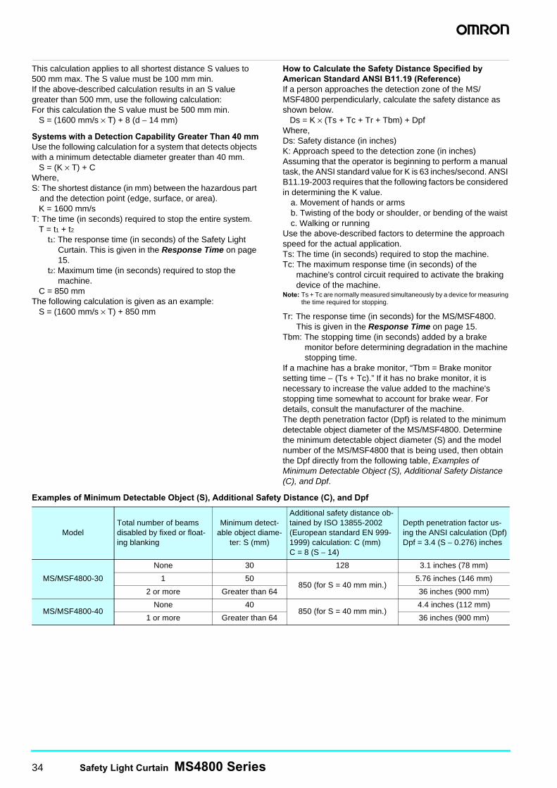
34 Safety Light Curtain MS4800 Series
This calculation applies to all shortest distance S values to 500 mm max. The S value must be 100 mm min.If the above-described calculation results in an S value greater than 500 mm, use the following calculation:For this calculation the S value must be 500 mm min. S = (1600 mm/s × T) + 8 (d − 14 mm)
Systems with a Detection Capability Greater Than 40 mmUse the following calculation for a system that detects objects with a minimum detectable diameter greater than 40 mm. S = (K × T) + CWhere,S: The shortest distance (in mm) between the hazardous part
and the detection point (edge, surface, or area). K = 1600 mm/sT: The time (in seconds) required to stop the entire system. T = t1 + t2
t1: The response time (in seconds) of the Safety Light Curtain. This is given in the Response Time on page 15.
t2: Maximum time (in seconds) required to stop the machine.
C = 850 mmThe following calculation is given as an example: S = (1600 mm/s × T) + 850 mm
How to Calculate the Safety Distance Specified by American Standard ANSI B11.19 (Reference)If a person approaches the detection zone of the MS/MSF4800 perpendicularly, calculate the safety distance as shown below. Ds = K × (Ts + Tc + Tr + Tbm) + DpfWhere,Ds: Safety distance (in inches)K: Approach speed to the detection zone (in inches)Assuming that the operator is beginning to perform a manual task, the ANSI standard value for K is 63 inches/second. ANSI B11.19-2003 requires that the following factors be considered in determining the K value.
a. Movement of hands or armsb. Twisting of the body or shoulder, or bending of the waist c. Walking or running
Use the above-described factors to determine the approach speed for the actual application.Ts: The time (in seconds) required to stop the machine.Tc: The maximum response time (in seconds) of the
machine's control circuit required to activate the braking device of the machine.
Note: Ts + Tc are normally measured simultaneously by a device for measuring the time required for stopping.
Tr: The response time (in seconds) for the MS/MSF4800.This is given in the Response Time on page 15.
Tbm: The stopping time (in seconds) added by a brake monitor before determining degradation in the machine stopping time.
If a machine has a brake monitor, “Tbm = Brake monitor setting time − (Ts + Tc).” If it has no brake monitor, it is necessary to increase the value added to the machine's stopping time somewhat to account for brake wear. For details, consult the manufacturer of the machine.The depth penetration factor (Dpf) is related to the minimum detectable object diameter of the MS/MSF4800. Determine the minimum detectable object diameter (S) and the model number of the MS/MSF4800 that is being used, then obtain the Dpf directly from the following table, Examples of Minimum Detectable Object (S), Additional Safety Distance (C), and Dpf.
Examples of Minimum Detectable Object (S), Additional Safety Distance (C), and Dpf
ModelTotal number of beams disabled by fixed or float-ing blanking
Minimum detect-able object diame-
ter: S (mm)
Additional safety distance ob-tained by ISO 13855-2002 (European standard EN 999-1999) calculation: C (mm)C = 8 (S − 14)
Depth penetration factor us-ing the ANSI calculation (Dpf)Dpf = 3.4 (S − 0.276) inches
MS/MSF4800-30
None 30 128 3.1 inches (78 mm)
1 50850 (for S = 40 mm min.)
5.76 inches (146 mm)
2 or more Greater than 64 36 inches (900 mm)
MS/MSF4800-40None 40
850 (for S = 40 mm min.)4.4 inches (112 mm)
1 or more Greater than 64 36 inches (900 mm)
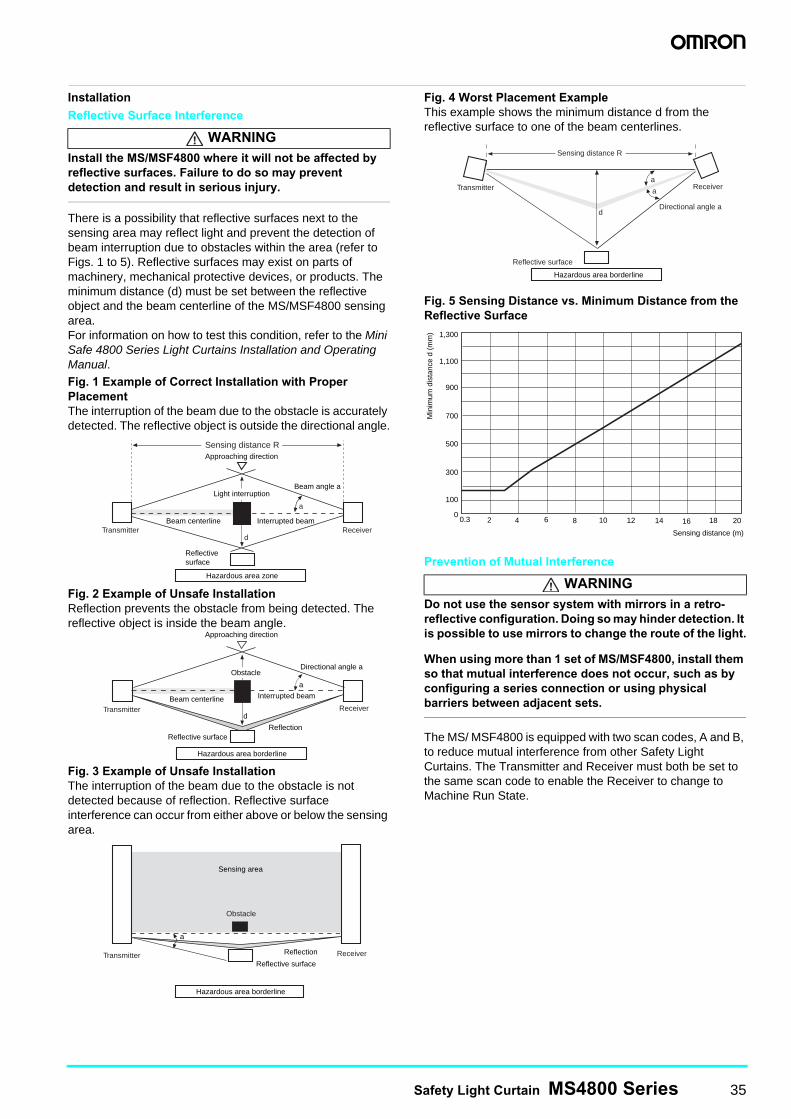
Safety Light Curtain MS4800 Series 35
Installation
Reflective Surface Interference
Install the MS/MSF4800 where it will not be affected by reflective surfaces. Failure to do so may prevent detection and result in serious injury.
There is a possibility that reflective surfaces next to the sensing area may reflect light and prevent the detection of beam interruption due to obstacles within the area (refer to Figs. 1 to 5). Reflective surfaces may exist on parts of machinery, mechanical protective devices, or products. The minimum distance (d) must be set between the reflective object and the beam centerline of the MS/MSF4800 sensing area.For information on how to test this condition, refer to the Mini Safe 4800 Series Light Curtains Installation and Operating Manual.Fig. 1 Example of Correct Installation with Proper PlacementThe interruption of the beam due to the obstacle is accurately detected. The reflective object is outside the directional angle.
Fig. 2 Example of Unsafe InstallationReflection prevents the obstacle from being detected. The reflective object is inside the beam angle.
Fig. 3 Example of Unsafe InstallationThe interruption of the beam due to the obstacle is not detected because of reflection. Reflective surface interference can occur from either above or below the sensing area.
Fig. 4 Worst Placement ExampleThis example shows the minimum distance d from the reflective surface to one of the beam centerlines.
Fig. 5 Sensing Distance vs. Minimum Distance from the Reflective Surface
Prevention of Mutual Interference
Do not use the sensor system with mirrors in a retro-reflective configuration. Doing so may hinder detection. It is possible to use mirrors to change the route of the light.
When using more than 1 set of MS/MSF4800, install them so that mutual interference does not occur, such as by configuring a series connection or using physical barriers between adjacent sets.
The MS/ MSF4800 is equipped with two scan codes, A and B, to reduce mutual interference from other Safety Light Curtains. The Transmitter and Receiver must both be set to the same scan code to enable the Receiver to change to Machine Run State.
WARNING
d
a
Transmitter Receiver
Approaching direction
Beam centerline Interrupted beam
Light interruption
Hazardous area zone
Reflectivesurface
Beam angle a
Sensing distance R
d
Hazardous area borderline
Reflection
Obstacle
a
Directional angle a
Interrupted beam
Receiver
Approaching direction
Beam centerline
Reflective surface
Transmitter
Sensing area
Hazardous area borderline
ReceiverReflective surface
Reflection
a
Obstacle
Transmitter
WARNING
Receiver
Directional angle ad
Reflective surface
Sensing distance R
a
a
Hazardous area borderline
Transmitter
0
100
300
500
700
900
2 4 6 8 10 12 14 16
Sensing distance (m)
18 20
1,100
1,300
0.3
Min
imum
dis
tanc
e d
(mm
)
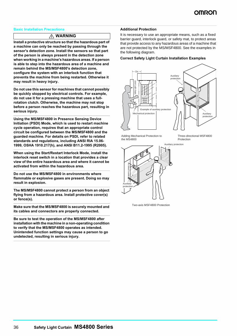
36 Safety Light Curtain MS4800 Series
Basic Installation Precautions
Install a protective structure so that the hazardous part of a machine can only be reached by passing through the sensor's detection zone. Install the sensors so that part of the person is always present in the detection zone when working in a machine's hazardous areas. If a person is able to step into the hazardous area of a machine and remain behind the MS/MSF4800's detection zone, configure the system with an interlock function that prevents the machine from being restarted. Otherwise it may result in heavy injury.
Do not use this sensor for machines that cannot possibly be quickly stopped by electrical controls. For example, do not use it for a pressing machine that uses a full-rotation clutch. Otherwise, the machine may not stop before a person reaches the hazardous part, resulting in serious injury.
Using the MS/MSF4800 in Presence Sensing Device Initiation (PSDI) Mode, which is used to restart machine cycle operation, requires that an appropriate control circuit be configured between the MS/MSF4800 and the guarded machine. For details on PSDI, refer to related standards and regulations, including ANSI RIA 15.06-1999, OSHA 1910.217(h), and ANSI B11.2-1995 (R2005).
When using the Start/Restart Interlock Mode, install the interlock reset switch in a location that provides a clear view of the entire hazardous area and where it cannot be activated from within the hazardous area.
Do not use the MS/MSF4800 in environments where flammable or explosive gases are present. Doing so may result in explosion.
The MS/MSF4800 cannot protect a person from an object flying from a hazardous area. Install protective cover(s) or fence(s).
Make sure that the MS/MSF4800 is securely mounted and its cables and connectors are properly connected.
Be sure to test the operation of the MS/MSF4800 after installation with the machine in a non-operating condition to verify that the MS/MSF4800 operates as intended. Unintended function settings may cause a person to go undetected, resulting in serious injury.
Additional Protection
It is necessary to use an appropriate means, such as a fixed barrier guard, interlock guard, or safety mat, to protect areas that provide access to any hazardous areas of a machine that are not protected by the MS/MSF4800. See the examples in the following diagram.
Correct Safety Light Curtain Installation Examples
WARNING
Auxiliary protection
Auxiliary protection
Auxiliary protection
Auxiliary protection
Ds
Example of auxiliary protection
Mechanical protection
Two-axis MSF4800 Protection
Three-directional MSF4800 Protection
Adding Mechanical Protection tothe MS4800
Safe
ty Lig
ht C
urta
in
Hazar-dousarea
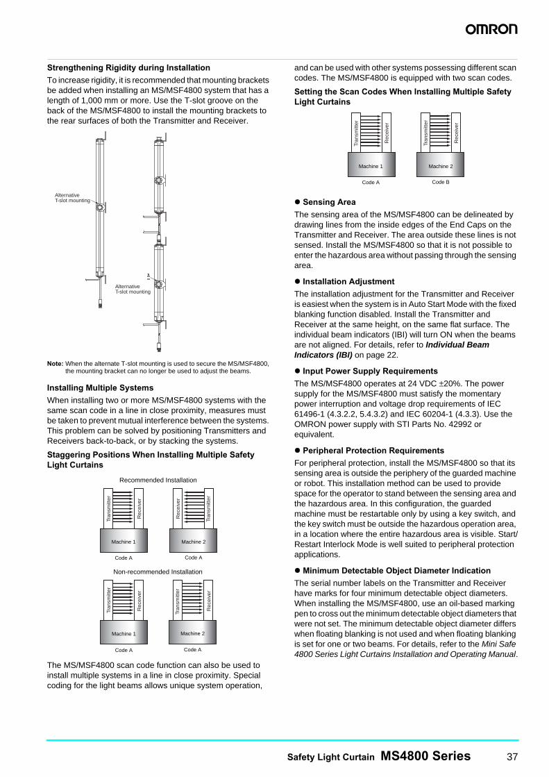
Safety Light Curtain MS4800 Series 37
Strengthening Rigidity during Installation
To increase rigidity, it is recommended that mounting brackets be added when installing an MS/MSF4800 system that has a length of 1,000 mm or more. Use the T-slot groove on the back of the MS/MSF4800 to install the mounting brackets to the rear surfaces of both the Transmitter and Receiver.
Note: When the alternate T-slot mounting is used to secure the MS/MSF4800, the mounting bracket can no longer be used to adjust the beams.
Installing Multiple Systems
When installing two or more MS/MSF4800 systems with the same scan code in a line in close proximity, measures must be taken to prevent mutual interference between the systems. This problem can be solved by positioning Transmitters and Receivers back-to-back, or by stacking the systems.
Staggering Positions When Installing Multiple Safety Light Curtains
The MS/MSF4800 scan code function can also be used to install multiple systems in a line in close proximity. Special coding for the light beams allows unique system operation,
and can be used with other systems possessing different scan codes. The MS/MSF4800 is equipped with two scan codes.
Setting the Scan Codes When Installing Multiple Safety Light Curtains
Sensing Area
The sensing area of the MS/MSF4800 can be delineated by drawing lines from the inside edges of the End Caps on the Transmitter and Receiver. The area outside these lines is not sensed. Install the MS/MSF4800 so that it is not possible to enter the hazardous area without passing through the sensing area.
Installation Adjustment
The installation adjustment for the Transmitter and Receiver is easiest when the system is in Auto Start Mode with the fixed blanking function disabled. Install the Transmitter and Receiver at the same height, on the same flat surface. The individual beam indicators (IBI) will turn ON when the beams are not aligned. For details, refer to Individual Beam Indicators (IBI) on page 22.
Input Power Supply Requirements
The MS/MSF4800 operates at 24 VDC ±20%. The power supply for the MS/MSF4800 must satisfy the momentary power interruption and voltage drop requirements of IEC 61496-1 (4.3.2.2, 5.4.3.2) and IEC 60204-1 (4.3.3). Use the OMRON power supply with STI Parts No. 42992 or equivalent.
Peripheral Protection Requirements
For peripheral protection, install the MS/MSF4800 so that its sensing area is outside the periphery of the guarded machine or robot. This installation method can be used to provide space for the operator to stand between the sensing area and the hazardous area. In this configuration, the guarded machine must be restartable only by using a key switch, and the key switch must be outside the hazardous operation area, in a location where the entire hazardous area is visible. Start/Restart Interlock Mode is well suited to peripheral protection applications.
Minimum Detectable Object Diameter Indication
The serial number labels on the Transmitter and Receiver have marks for four minimum detectable object diameters. When installing the MS/MSF4800, use an oil-based marking pen to cross out the minimum detectable object diameters that were not set. The minimum detectable object diameter differs when floating blanking is not used and when floating blanking is set for one or two beams. For details, refer to the Mini Safe 4800 Series Light Curtains Installation and Operating Manual.
Alternative T-slot mounting
Alternative T-slot mounting
Machine 1 Machine 2
Recommended Installation
Code A Code A
Machine 1 Machine 2
Non-recommended Installation
Code A Code A
Tran
smitt
er
Rec
eive
r
Rec
eive
r
Rec
eive
r
Rec
eive
rTr
ansm
itter
Tran
smitt
er
Tran
smitt
er
Machine 1 Machine 2
Code A Code B
Tran
smitt
er
Rec
eive
r
Rec
eive
r
Tran
smitt
er
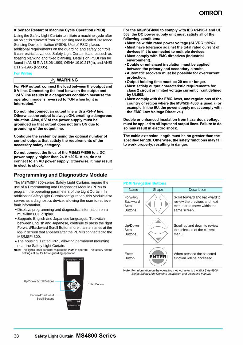
38 Safety Light Curtain MS4800 Series
Sensor Restart of Machine Cycle Operation (PSDI)
Using the Safety Light Curtain to initiate a machine cycle after an object is removed from the sensing area is called Presence Sensing Device Initiation (PSDI). Use of PSDI places additional requirements on the guarding and safety controls. It can restrict advanced Safety Light Curtain features such as floating blanking and fixed blanking. Details on PSDI can be found in ANSI RIA 15.06-1999, OSHA 1910.217(h), and ANSI B11.2-1995 (R2005).
For Wiring
For PNP output, connect the load between the output and 0 V line. Connecting the load between the output and +24 V line results in a dangerous condition because the operation mode is reversed to “ON when light is interrupted.”
Do not interconnect an output line with a +24-V line. Otherwise, the output is always ON, creating a dangerous situation. Also, 0 V of the power supply must be grounded so that output does not turn ON due to grounding of the output line.
Configure the system by using the optimal number of control outputs that satisfy the requirements of the necessary safety category.
Do not connect the lines of the MS/MSF4800 to a DC power supply higher than 24 V +20%. Also, do not connect to an AC power supply. Otherwise, it may result in electric shock.
For the MS/MSF4800 to comply with IEC 61496-1 and UL 508, the DC power supply unit must satisfy all of the following conditions:• Must be within rated power voltage (24 VDC ±20%).• Must have tolerance against the total rated current of
devices if it is connected to multiple devices.• Must comply with EMC directives (industrial
environment).• Double or enhanced insulation must be applied
between the primary and secondary circuits.• Automatic recovery must be possible for overcurrent
protection.• Output holding time must be 20 ms or longer.• Must satisfy output characteristic requirements for
class 2 circuit or limited voltage current circuit defined by UL508.
• Must comply with the EMC, laws, and regulations of the country or region where the MS/MSF4800 is used. (For example, in the EU, the power supply must comply with the EMC Low Voltage Directive.)
Double or enhanced insulation from hazardous voltage must be applied to all input and output lines. Failure to do so may result in electric shock.
The cable extension length must be no greater than the specified length. Otherwise, the safety functions may fail to work properly, resulting in danger.
Programming and Diagnostics ModuleThe MS/MSF4800-series Safety Light Curtains require the use of a Programming and Diagnostics Module (PDM) to program the operating parameters of the Light Curtain. In addition to Safety Light Curtain configuration, this Module also serves as a diagnostics device, allowing the user to retrieve fault information.• Displays programming and diagnostics information on a
multi-line LCD display.• Supports English and Japanese languages. To switch
between English and Japanese, continue to press the right Forward/Backward Scroll Button more than ten times at the log-in screen that appears after the PDM is connected to the MS/MSF4800.
• The housing is rated IP65, allowing permanent mounting near the Safety Light Curtain.
Note: The light curtain does not require the PDM to operate. The factory default settings allow for basic guarding operation.
PDM Navigation Buttons
Note: For information on the operating method, refer to the Mini Safe 4800 Series Safety Light Curtains Installation and Operating Manual.
WARNING
Up/Down Scroll ButtonsEnter Button
Forward/BackwardScroll Buttons
Name Shape Description
Forward/Backward Scroll Buttons
Scroll forward and backward to review the previous and next menu, or to move within the same screen.
Up/Down Scroll Buttons
Scroll up and down to review the selection of the current menu.
Enter Button
When pressed the selected function will be accessed.

Safety Light Curtain MS4800 Series 39

Authorized Distributor:
In the interest of product improvement, specifications are subject to change without notice.
© OMRON Corporation 2009 All Rights Reserved.
OMRON Corporation Industrial Automation Company
Regional HeadquartersOMRON EUROPE B.V.Wegalaan 67-69-2132 JD HoofddorpThe NetherlandsTel: (31)2356-81-300/Fax: (31)2356-81-388
Contact: www.ia.omron.comTokyo, JAPAN
OMRON ASIA PACIFIC PTE. LTD.No. 438A Alexandra Road # 05-05/08 (Lobby 2), Alexandra Technopark, Singapore 119967Tel: (65) 6835-3011/Fax: (65) 6835-2711
OMRON (CHINA) CO., LTD.Room 2211, Bank of China Tower, 200 Yin Cheng Zhong Road, PuDong New Area, Shanghai, 200120, ChinaTel: (86) 21-5037-2222/Fax: (86) 21-5037-2200
OMRON SCIENTIFIC TECHNOLOGIES INC.6550 Dumbarton Circle, FremontCA 94555-3605 U.S.A.Tel: (1) 510-608-3400/Fax: (1) 510-744-1442
Cat. No. F084-E1-01Printed in Japan
0408-3M (0408) (C)CSM_7_1_0214