Embed Size (px)
Citation preview
Cisco Systems, Inc.All contents are Copyright © 1992–2004 Cisco Systems, Inc. All rights reserved. Import
Page 1 of 22
SOLUTION OVERVIEW
NEXT GENERATION NETWORKS AND
THE CISCO CARRIER ROUTING SYSTEM
This solution overview describes the next generation of service provider networks, outlines
steps for building converged packet infrastructures, identifies the requirements that
converged packet infrastructures will place on next generation core routing systems, and
introduces the Cisco® CRS-1 Carrier Routing System, the premier Cisco Systems® solution
designed to exceed these requirements today and for decades to come.
THE VISION OF NEXT GENERATION NETWORKS AND CONVERGED PACKET
INFRASTRUCTURES
Service providers worldwide are striving to deploy new solutions that can adequately address the
demands being placed on them by their customers and investors:
Demands from businesses for:
• Integrated data, voice, and video
• Any service, anywhere, with high speeds and media flexibility
• On-demand provisioning of circuits, bandwidth, and services
• Flexible Virtual Private Network (VPN) solutions
• More innovative services and network intelligence—security, storage, application layer routing,
and adaptability—to support the trend in enterprise markets toward better integration of their
networking and information systems
Demands from consumers and governments for:
• Broadband access to every home
• Business-class telecommuting—High-performance, highly available, and secure to support the
growing population of telecommuters who work from home or abroad
• Attractive pricing bundles for data, voice, and video services, with both wireline and wireless
access methods
• Firewalls and intrusion protection
• On-demand video services
• High-speed peer-to-peer networking and applications
Demands from investors include:
• Increased revenue
• Improved profitability
• Broader service areas
• Greater productivity
ant Notices and Privacy Statement.
All content
Many service providers are finding it progressively more challenging to address these market demands using their
existing solutions, which include:
• Offering data, voice, and video services over complex collections of service-specific networks that are costly to
operate and unable to deliver the flexible, integrated services demanded by the market
• Deploying a broad range of access methods and protocols that are better suited to providing connectivity than
differentiated, profitable services
• Building IP/MPLS networks using complex, redundant architectures that cannot deliver the levels of reliability,
efficiency, and flexibility demanded by the market
As a means to address these challenges and market demands, a new vision is gaining momentum in the
telecommunications industry—the vision of one network for all services—a next generation network that delivers:
• The mobility of wireless networks
• The reliability of the public switched telephone network (PSTN)
• The broad reach of the Internet
• The security and service isolation of private lines
• The flexibility of IP and Multiprotocol Label Switching (MPLS) to support integrated data, voice, and video
services
• The high capacity of optical networks
• The operational efficiency of a common, consistent infrastructure
Many service providers agree that next generation networks will be built on a new foundation – a converged packet
infrastructure formed from three fundamental elements:
• Infrastructure convergence—The convergence of multiple service-specific networks onto a common MPLS core
through the use of Multiservice Edge (MSE) routers that deliver Layer 2 and Layer 3 VPN services
• Service convergence—The convergence of data, voice, and video services onto flexible and ubiquitous IP/MPLS
• Network simplification—The simplification of network architectures—specifically Point-of-Presence (POP)
architectures—through the elimination of complex tiering and redundancy to create more scalable, reliable, and
manageable IP/MPLS networks
INFRASTRUCTURE CONVERGENCE
Today, many service providers are operating infrastructures built from multiple service-specific networks that have
evolved in parallel with the many technologies that have appeared over the past several decades (refer to Figure 1).
These complex, hybrid infrastructures typically include:
• Frame Relay networks (using ATM for a core backbone) for providing Layer 2 data services—These networks
deliver fairly limited bandwidth, typically less than 1 Mbps, and impose strict media and topology restrictions
that make them less capable of meeting today’s demands.
• SONET/SDH networks for long-haul private-line services—SONET/SDH can transport data, voice, and video
easily, but requires fixed, dedicated bandwidth. The availability of SONET/SDH is limited, as is its
interoperability with other Layer 2 services
Cisco Systems, Inc.s are Copyright © 1992–2004 Cisco Systems, Inc. All rights reserved. Important Notices and Privacy Statement.
Page 2 of 22
All content
• Metro Ethernet networks offer improvements over the bandwidth and topology restrictions of Frame Relay, but
their limited geographical reach and lack of interoperability with Frame Relay and SONET/SDH services limit
flexibility
• Voice services delivered over TDM have become commoditized, in part due to the historically slow product
development cycles and the inflexible nature of this technology
• Private IP and Internet-access networks delivered over distinct infrastructures
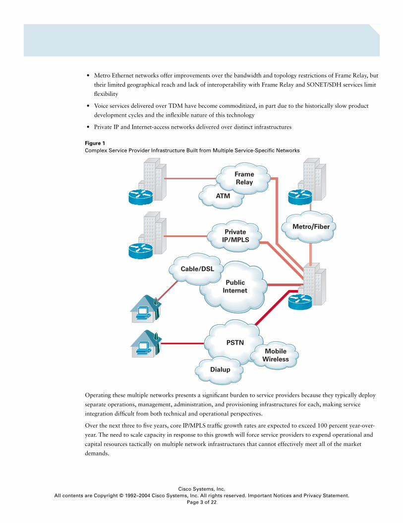
Figure 1
Complex Service Provider Infrastructure Built from Multiple Service-Specific Networks
Operating these multiple networks presents a significant burden to service providers because they typically deploy
separate operations, management, administration, and provisioning infrastructures for each, making service
integration difficult from both technical and operational perspectives.
Over the next three to five years, core IP/MPLS traffic growth rates are expected to exceed 100 percent year-over-
year. The need to scale capacity in response to this growth will force service providers to expend operational and
capital resources tactically on multiple network infrastructures that cannot effectively meet all of the market
demands.
/
Cisco Systems, Inc.s are Copyright © 1992–2004 Cisco Systems, Inc. All rights reserved. Important Notices and Privacy Statement.
Page 3 of 22
All content
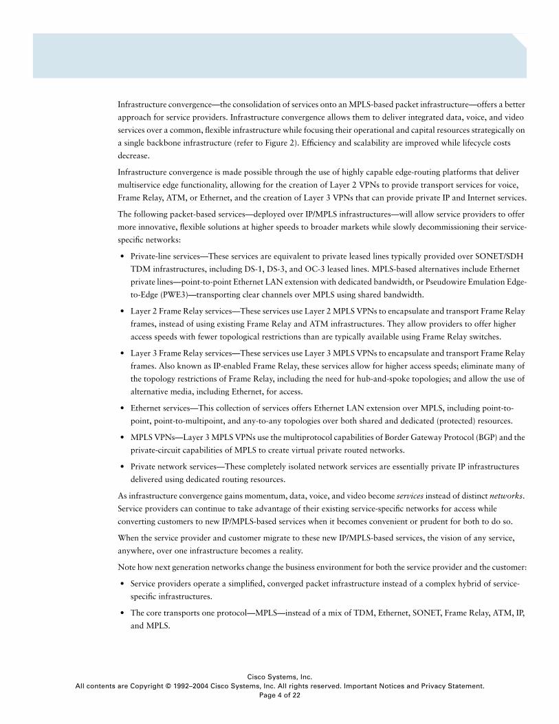
Infrastructure convergence—the consolidation of services onto an MPLS-based packet infrastructure—offers a better
approach for service providers. Infrastructure convergence allows them to deliver integrated data, voice, and video
services over a common, flexible infrastructure while focusing their operational and capital resources strategically on
a single backbone infrastructure (refer to Figure 2). Efficiency and scalability are improved while lifecycle costs
decrease.
Infrastructure convergence is made possible through the use of highly capable edge-routing platforms that deliver
multiservice edge functionality, allowing for the creation of Layer 2 VPNs to provide transport services for voice,
Frame Relay, ATM, or Ethernet, and the creation of Layer 3 VPNs that can provide private IP and Internet services.
The following packet-based services—deployed over IP/MPLS infrastructures—will allow service providers to offer
more innovative, flexible solutions at higher speeds to broader markets while slowly decommissioning their service-
specific networks:
• Private-line services—These services are equivalent to private leased lines typically provided over SONET/SDH
TDM infrastructures, including DS-1, DS-3, and OC-3 leased lines. MPLS-based alternatives include Ethernet
private lines—point-to-point Ethernet LAN extension with dedicated bandwidth, or Pseudowire Emulation Edge-
to-Edge (PWE3)—transporting clear channels over MPLS using shared bandwidth.
• Layer 2 Frame Relay services—These services use Layer 2 MPLS VPNs to encapsulate and transport Frame Relay
frames, instead of using existing Frame Relay and ATM infrastructures. They allow providers to offer higher
access speeds with fewer topological restrictions than are typically available using Frame Relay switches.
• Layer 3 Frame Relay services—These services use Layer 3 MPLS VPNs to encapsulate and transport Frame Relay
frames. Also known as IP-enabled Frame Relay, these services allow for higher access speeds; eliminate many of
the topology restrictions of Frame Relay, including the need for hub-and-spoke topologies; and allow the use of
alternative media, including Ethernet, for access.
• Ethernet services—This collection of services offers Ethernet LAN extension over MPLS, including point-to-
point, point-to-multipoint, and any-to-any topologies over both shared and dedicated (protected) resources.
• MPLS VPNs—Layer 3 MPLS VPNs use the multiprotocol capabilities of Border Gateway Protocol (BGP) and the
private-circuit capabilities of MPLS to create virtual private routed networks.
• Private network services—These completely isolated network services are essentially private IP infrastructures
delivered using dedicated routing resources.
As infrastructure convergence gains momentum, data, voice, and video become services instead of distinct networks.
Service providers can continue to take advantage of their existing service-specific networks for access while
converting customers to new IP/MPLS-based services when it becomes convenient or prudent for both to do so.
When the service provider and customer migrate to these new IP/MPLS-based services, the vision of any service,
anywhere, over one infrastructure becomes a reality.
Note how next generation networks change the business environment for both the service provider and the customer:
• Service providers operate a simplified, converged packet infrastructure instead of a complex hybrid of service-
specific infrastructures.
• The core transports one protocol—MPLS—instead of a mix of TDM, Ethernet, SONET, Frame Relay, ATM, IP,
and MPLS.
Cisco Systems, Inc.s are Copyright © 1992–2004 Cisco Systems, Inc. All rights reserved. Important Notices and Privacy Statement.
Page 4 of 22
All content
• Service providers can sell bandwidth and innovative new services based on IP/MPLS instead of selling
connectivity and bandwidth.
• Services are available anywhere IP/MPLS can reach, instead of being limited by the capabilities and reach of
service-specific networks and protocols.
• Provisioning changes from slow and difficult to on demand, or even automatic because of the elimination of
separate network administration and provisioning infrastructures.
• Growth is no longer limited by infrastructure but is enabled by the flexibility of IP/MPLS and its ability to deliver
flexible and integrated services to any customer over any medium.
• Operational and capital costs are reduced as service-specific networks and operations infrastructures are
consolidated or decommissioned over time.
Figure 2
Infrastructure Convergence, Where Data, Voice, and Video Services Are Delivered over a Common IP/MPLS-Based Packet Infrastructure
SERVICE CONVERGENCE
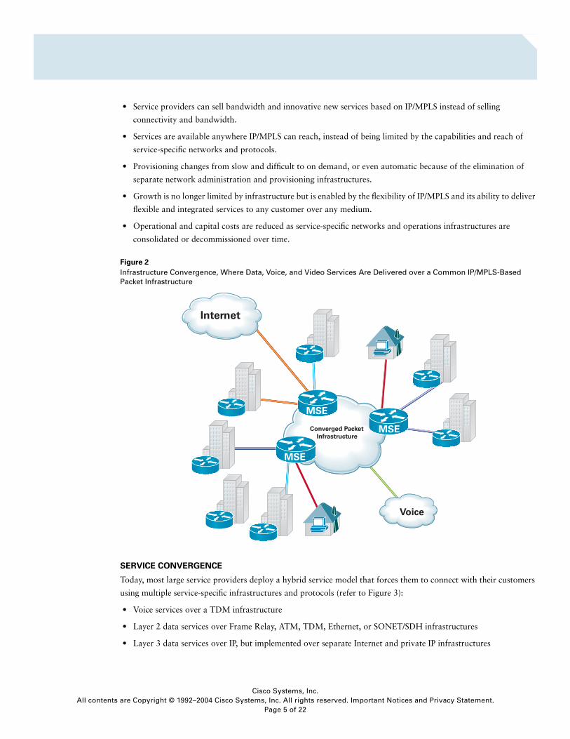
Today, most large service providers deploy a hybrid service model that forces them to connect with their customers
using multiple service-specific infrastructures and protocols (refer to Figure 3):
• Voice services over a TDM infrastructure
• Layer 2 data services over Frame Relay, ATM, TDM, Ethernet, or SONET/SDH infrastructures
• Layer 3 data services over IP, but implemented over separate Internet and private IP infrastructures
MSE
MSE
MSE
Cisco Systems, Inc.s are Copyright © 1992–2004 Cisco Systems, Inc. All rights reserved. Important Notices and Privacy Statement.
Page 5 of 22
All content
Figure 3
A Typical Complex Mix of Services and Protocols Offered by Service Providers to Meet the Various Communications Needs of Enterprise Customers
Although all the basic services that customers need to operate their businesses are available, both customers and
service providers are burdened by the need to manage and maintain multiple service interfaces and infrastructures,
and more significantly, they are burdened by the inability of these infrastructures—with the exception of those based
on IP/MPLS—to evolve to deliver new services in any location, over any medium. For example:
• Traditional voice services and infrastructures offer limited opportunities for value-added services or service
differentiation; these limitations lead to commoditization and diminished profit potential in a highly competitive
environment.
• Frame Relay services, although widely deployed, these services impose strict bandwidth, media, and topology
restrictions.
• Fixed-bandwidth TDM and SONET/SDH-based services are expensive for both customers and service providers
because they require the strict dedication of bandwidth and resources to a specific service and customer.
• Metropolitan (Metro) Ethernet services, although offering higher speeds, do not interoperate easily with Frame
Relay, ATM, or other Layer 2 services.
Cisco Systems, Inc.s are Copyright © 1992–2004 Cisco Systems, Inc. All rights reserved. Important Notices and Privacy Statement.
Page 6 of 22
All content
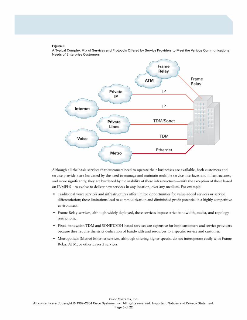
Service convergence is the migration of critical data, voice, and video services onto packet transport protocols—either
IP or MPLS (refer to Figure 4). These protocols provide excellent transport solutions for these services because of
their flexibility, ubiquity, and the ability of advanced routing infrastructures to deliver circuit-like quality of service
and service isolation.
The flexibility and adaptability of IP and MPLS also allow service providers to deliver innovative service offerings in
addition to data, voice, and video, such as security (managed firewall and intrusion detection systems), storage, on-
demand video—all over any media—truly any service, anywhere.
Figure 4
Integrated Data, Voice, and Video Services Delivered over Flexible, Ubiquitous IP/MPLS
Cisco Systems, Inc.s are Copyright © 1992–2004 Cisco Systems, Inc. All rights reserved. Important Notices and Privacy Statement.
Page 7 of 22
All content
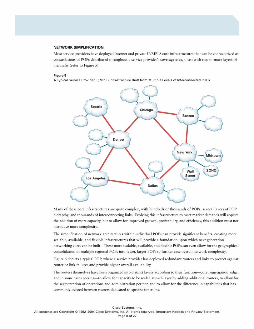
NETWORK SIMPLIFICATION
Most service providers have deployed Internet and private IP/MPLS core infrastructures that can be characterized as
constellations of POPs distributed throughout a service provider’s coverage area, often with two or more layers of
hierarchy (refer to Figure 5).
Figure 5
A Typical Service Provider IP/MPLS Infrastructure Built from Multiple Levels of Interconnected POPs
Many of these core infrastructures are quite complex, with hundreds or thousands of POPs, several layers of POP
hierarchy, and thousands of interconnecting links. Evolving this infrastructure to meet market demands will require
the addition of more capacity, but to allow for improved growth, profitability, and efficiency, this addition must not
introduce more complexity.
The simplification of network architectures within individual POPs can provide significant benefits, creating more
scalable, available, and flexible infrastructures that will provide a foundation upon which next generation
networking cores can be built. These more scalable, available, and flexible POPs can even allow for the geographical
consolidation of multiple regional POPs into fewer, larger POPs to further ease overall network complexity.
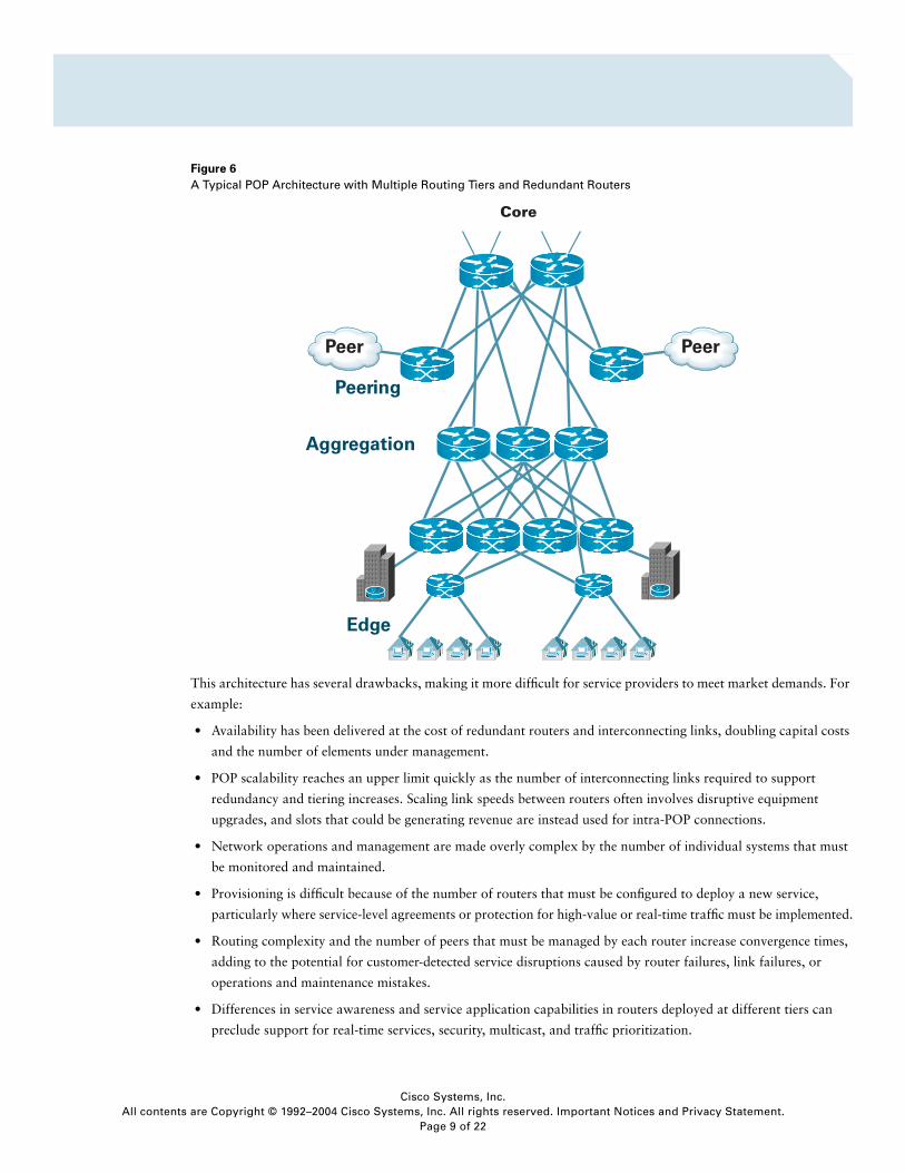
Figure 6 depicts a typical POP, where a service provider has deployed redundant routers and links to protect against
router or link failures and provide higher overall availability.
The routers themselves have been organized into distinct layers according to their function—core, aggregation, edge,
and in some cases peering—to allow for capacity to be scaled at each layer by adding additional routers, to allow for
the segmentation of operations and administration per tier, and to allow for the difference in capabilities that has
commonly existed between routers dedicated to specific functions.
Cisco Systems, Inc.s are Copyright © 1992–2004 Cisco Systems, Inc. All rights reserved. Important Notices and Privacy Statement.
Page 8 of 22
All content
Figure 6
A Typical POP Architecture with Multiple Routing Tiers and Redundant Routers
This architecture has several drawbacks, making it more difficult for service providers to meet market demands. For
example:
• Availability has been delivered at the cost of redundant routers and interconnecting links, doubling capital costs
and the number of elements under management.
• POP scalability reaches an upper limit quickly as the number of interconnecting links required to support
redundancy and tiering increases. Scaling link speeds between routers often involves disruptive equipment
upgrades, and slots that could be generating revenue are instead used for intra-POP connections.
• Network operations and management are made overly complex by the number of individual systems that must
be monitored and maintained.
• Provisioning is difficult because of the number of routers that must be configured to deploy a new service,
particularly where service-level agreements or protection for high-value or real-time traffic must be implemented.
• Routing complexity and the number of peers that must be managed by each router increase convergence times,
adding to the potential for customer-detected service disruptions caused by router failures, link failures, or
operations and maintenance mistakes.
• Differences in service awareness and service application capabilities in routers deployed at different tiers can
preclude support for real-time services, security, multicast, and traffic prioritization.
Core
Cisco Systems, Inc.s are Copyright © 1992–2004 Cisco Systems, Inc. All rights reserved. Important Notices and Privacy Statement.
Page 9 of 22
All content
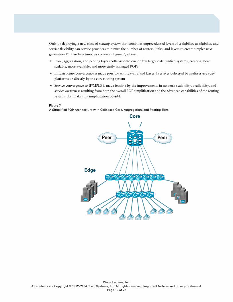
Only by deploying a new class of routing system that combines unprecedented levels of scalability, availability, and
service flexibility can service providers minimize the number of routers, links, and layers to create simpler next
generation POP architectures, as shown in Figure 7, where:
• Core, aggregation, and peering layers collapse onto one or few large-scale, unified systems, creating more
scalable, more available, and more easily managed POPs
• Infrastructure convergence is made possible with Layer 2 and Layer 3 services delivered by multiservice edge
platforms or directly by the core routing system
• Service convergence to IP/MPLS is made feasible by the improvements in network scalability, availability, and
service awareness resulting from both the overall POP simplification and the advanced capabilities of the routing
systems that make this simplification possible
Figure 7
A Simplified POP Architecture with Collapsed Core, Aggregation, and Peering Tiers
Cisco Systems, Inc.s are Copyright © 1992–2004 Cisco Systems, Inc. All rights reserved. Important Notices and Privacy Statement.
Page 10 of 22
All content
REQUIREMENTS FOR CONVERGED PACKET INFRASTRUCTURES
Infrastructure convergence, service convergence, and network simplification will impose demanding—even
conflicting—requirements on the routers and routing systems that form the foundation for converged packet
infrastructures.
Massive Scalability and Simplicity
Converged packet infrastructures will eventually provide critical transport for most or all of a service provider’s data,
voice, and video service offerings, including consumer and business voice services, broadcast and on-demand video,
Layer 2 and Layer 3 VPN services, private IP, and Internet services. The sum of traffic from these and other sources
is expected to increase core IP/MPLS traffic at a rate exceeding 100 percent per year for the next three to five years,
and will require service providers to increase the size of their networks and POPs to accommodate this growth.
Scaling POPs using the traditional method of applying additional routers to the core, aggregation, peering, and edge
layers adds complexity, increases capital and operational costs, and increases the likelihood of service disruptions
caused by component failures, routing disturbances, and required forklift upgrades. This traditional method allows
scalability or simplicity, but not both.
Converged packet infrastructures will demand new routing systems that can provide massive interface and service
scalability over multiple decades without increasing POP or network complexity: both scalability and simplicity.
Continuous Availability and Service Adaptability
Because converged packet infrastructures will provide transport for a large number of critical services and
applications such as voice, storage, enterprise resource management transactions, and e-business, they must provide
unprecedented levels of availability—continuous availability. However, converged packet networks will also have to
be extremely adaptable to allow service providers to deliver innovative new services and react to new technologies,
standards, competitors, market conditions, and customer demands. The traditional methods of adapting to meet new
demands involve replacing routing platforms, platform components, or software—all of which are disruptive and
have a negative effect on network and service availability. Achieving continuous availability requires that systems
remain in place and in service, but adapting to new demands requires system or software upgrades. These traditional
methods allow for continuous availability or service adaptability, but not both.
Converged packet infrastructures demand a new routing system that can provide continuous system availability
while allowing service providers to adapt without disruption—via hardware and software upgrades—to new market
demands, new standards, and new technologies: both continuous availability and service adaptability.
Service Flexibility and High Performance
Many technologies are subject to certain immutable design trade-offs: Cars are fast or fuel-efficient; metals can be
hard and brittle or soft but flexible; and memory can be volatile and fast or persistent but slow. Routing technologies
have been subject to similar trade-offs. Routers based on general-purpose processors are extremely flexible but offer
moderate performance. Routers based on application-specific integrated circuits (ASICs) offer very high performance
but are very difficult to adapt to new services. Traditional router architectures have forced a compromise: service
flexibility or high performance, but not both.
Converged packet infrastructures demand a new class of routing technology that combines the high performance of
ASICs with the service intelligence of general-purpose CPUs, allowing service providers to deliver a full range of
services over any interface without performance compromises: both service flexibility and high performance.
Cisco Systems, Inc.s are Copyright © 1992–2004 Cisco Systems, Inc. All rights reserved. Important Notices and Privacy Statement.
Page 11 of 22
All content
For converged packet infrastructures, the key requirements of scalability, availability, and flexibility must be
redefined. Scalability must now be defined as to scale without adding complexity; availability must now be defined
as to remain continuously available even while adapting to new demands; and flexibility must now be defined as to
deliver rich services without impacting performance.
THE NEW SCALABILITY, AVAILABILITY, AND FLEXIBILITY
Converged packet infrastructures demand routing systems that meet the new definitions of scalability, availability,
and flexibility—combining massive scalability with simplicity, continuous availability with adaptability, and service
flexibility with high-performance.
Scalability
To allow service providers to become more innovative, become more efficient, and reduce capital and operational
costs, the routing systems deployed in converged packet infrastructures should deliver multi-decade longevity and all
the following features and capabilities:
• Interface—Simplified POP architectures will require routing systems that can deliver non-disruptive scalability to
thousands of physical interfaces and hundreds of thousands of logical interfaces. This will allow service providers
to simplify their POP architectures (and therefore their networks) by collapsing multiple layers—core,
aggregation, peering, and, assuming the necessary service capabilities, even edge—into one unified routing
system.
• Peering—Network simplification will lead to the elimination of dedicated peering layers and routers within POP
architectures and the migration of these peering connections to fewer or even one unified routing system. The
routing systems deployed as the foundation for converged packet infrastructures must be capable of managing
thousands of BGP peers while delivering an efficient, programmatic, rules-based method of implementing
complex routing policies.
• Adjacency—As routing systems grow to include thousands or even tens of thousands of interfaces, and networks
expand to include millions of routes, the number of adjacencies that must be maintained by the packet-
forwarding engines increases dramatically. Routers that implement single-stage forwarding architectures have
inherent scalability limitations because every forwarding engine must maintain state for every route and every
adjacency. Routing systems built for converged packet infrastructures will require a more efficient two-stage
forwarding architecture that vastly increases overall system scalability by requiring forwarding engines to
maintain state only for directly connected adjacencies.
• Route and path—Growth in the number of Internet routes, IPv6 routes, Layer 3 VPNs (and their attendant virtual
routing and forwarding tables), and MPLS label-switched paths (LSPs) that will form the foundation for many
new services will demand that the routing systems deployed in converged packet infrastructures be capable of
handling millions of routes and millions of LSPs.
• Control plane—Routing systems for converged packet infrastructures must be capable of maintaining state for
dozens of routing protocols, hundreds to thousands of peers, thousands to tens of thousands of interfaces, and
millions of routes and LSPs. This level of control-plane scalability requires hardware with a modular, extensible,
and distributed processing architecture and an operating system that provides highly granular process
distribution to available processing resources, implements a rich client-server model for critical control-plane
processes, and provides an extremely efficient mechanism for distributing reachability and other control data to
its forwarding engines.
Cisco Systems, Inc.s are Copyright © 1992–2004 Cisco Systems, Inc. All rights reserved. Important Notices and Privacy Statement.
Page 12 of 22
All content
• Management—Managing any routing system that delivers the interface, peering, route, and control-plane
scalability required by converged packet infrastructures will be inherently difficult without an Extensible Markup
Language (XML) management interface and embedded tools to correlate alarms and events, manage
configurations, monitor performance, secure devices, and perform accounting. Trying to poll, monitor, and
correlate the huge amounts of data generated by such large-scale systems using external management systems
would quickly overwhelm both the bandwidth and the processing capabilities of typical management platforms.
Routing systems that can collect, correlate, evaluate, and deliver only relevant, high-value data to its operators
will provide a huge operational advantage.
• Multicast—Applications such as packet-based broadcast video, database replication, streaming financial
information and other one-to-many data services will depend on IP Multicast for transport. Routing systems used
in converged packet infrastructures must be able to manage potentially millions of multicast groups and to
efficiently and quickly replicate multicast traffic to thousands or tens of thousands of interfaces without
introducing excessive delay or jitter in the multicast streams.
Availability
To provide the level of availability that customers will demand and applications will require—99.999-percent
availability or better—the heavily used routing systems on which converged packet infrastructures are built must
deliver:
• Operating system infrastructure protection—The foundation for any operating system, whether used in PCs,
supercomputers, or routing systems, is the operating system kernel. If the kernel is compromised, the operating
system fails, so routing systems used in converged packet infrastructures should rely on microkernel architectures
that force all but the most critical functions, such as memory management and thread distribution, outside of the
kernel. This prevents failures in applications, file systems, and even device drivers from causing widespread
service disruption.
• Process and thread protection—Operating systems of modern networks require tens of millions of lines of code
and thousands of individual processes to implement protocol stacks, management interfaces, control-plane
features, file systems, device drivers, and other critical services and features. To minimize the effect that any failure
in any of these processes can have on other processes, each process—even individual process threads—must
execute in its own protected memory space, and communications between processes must be accomplished
through well-defined, secure, and version-controlled application programming interfaces (APIs).
• In-service hardware and software upgrades—Routing systems deployed in simplified POP architectures for
converged packet infrastructures will be so heavily used that they cannot be taken out of service for any reason,
even to add or replace hardware, install new features or services, or apply patches or upgrades to software. All
upgrades, hardware and software, must be made without disruption and with minimal impact on customers,
routing peers, or network traffic.
• Nonstop forwarding and stateful switchover features—To support in-service software and hardware upgrades,
the Route Processors must be capable of transitioning from active to standby with zero packet loss and no
perceivable change in the routing topology, routing adjacencies, or routing protocol state.
• Software packaging—The ability to incrementally upgrade specific operating system packages or even specific
features is a critical requirement for routing systems that will be deployed for converged packet infrastructures.
These systems must remain in continuous service but retain the ability to deliver new features that can be
Cisco Systems, Inc.s are Copyright © 1992–2004 Cisco Systems, Inc. All rights reserved. Important Notices and Privacy Statement.
Page 13 of 22
All content
delivered, installed, and placed in service in a modular fashion. Software packaging also gives a service provider
the opportunity to qualify again only those portions of its operating system that change—instead of the entire
system—saving significant time and expense.
• Restartable processes—To support the required continuous system availability and allow for in-service software
upgrades and quick recovery from process or protocol failures with minimal disruption to customers or traffic,
it must be possible to restart critical control-plane processes both manually and automatically in response to a
process failure. Restartable processes allow system operators to restart perhaps as few as thousands of lines of
code instead of the millions that might compose the entire operating system.
• State checkpointing—Restarting critical processes such as routing protocols or signaling stacks in response to a
hardware failure, software failure, or software upgrade should not force the reestablishment of routing
adjacencies or signaling state. Routing systems deployed in converged packet infrastructures must be able to
maintain a memory or critical operating state across process restarts using some method of state checkpointing,
as is typically found in advanced database server systems.
• Configuration protection—As POP architectures are simplified and routing layers collapse onto fewer or even
onto one large routing system, service providers may elect to retain separate management structures for core,
peering, and edge services. Having the ability to effectively limit the administrative capabilities and scope of these
various groups is a requirement to help ensure system integrity and minimize the effects of unintentional
configuration errors.
Service Flexibility
To provide the level of availability customers will demand and applications will require—99.999-percent availability
or better—the routing systems on which converged packet infrastructures are built must deliver:
• Strict service separation—The large routing systems deployed in converged packet infrastructures will provide
transport for many different services: voice, video distribution, VPNs, Internet, and perhaps even private network
services for government agencies or large enterprises. The ability to provide virtual routing—separate routing and
forwarding tables per service maintained by a common operating system instance—will not be sufficient. True
logical routing will be required to help ensure complete separation of data, control, and management planes
between services, effectively allowing the service provider to create completely distinct logical routing systems
from one physical system.
• High-performance services—The elimination of routing tiers to form simplified POP architectures dictates the
collapse of many sophisticated functions and services onto routing systems that must provide core, peering, and
edge services. As previously noted, past routing architectures could offer either high performance with few
features, or many sophisticated features at the price of performance. Routing systems deployed for converged
packet infrastructures must overcome these restrictions and provide high-performance services to every interface
and customer with no performance compromises.
• Control-plane adaptability—Routing systems deployed for converged packet infrastructures must be capable of
delivering the processing power to manage thousands of peers, millions of routes, and dozens or more true logical
routers in a single physical system. To service these requirements as they grow, routing systems must have a
modular hardware architecture that allows the addition of more processors and a modular operating system that
can effectively leverage these processors as they are added.
Cisco Systems, Inc.s are Copyright © 1992–2004 Cisco Systems, Inc. All rights reserved. Important Notices and Privacy Statement.
Page 14 of 22
All content
• Interface flexibility—Any routing system deployed in simplified POP architectures where core, peering,
aggregation, and edge routing tiers collapse must provide significant interface flexibility, ranging from DS-3 to
Channelized SONET and Gigabit Ethernet interfaces, and including the capability to mix interface types even
within individual slots.
• Forwarding-engine flexibility—Building converged packet infrastructures will require service providers to make
significant investments in new routing systems that deliver the required scalability, availability, and service
flexibility. Many of these investments will be in long-lived assets such as chassis, power, cooling, control-plane
processors, and physical Interface Modules. So that these assets can be redeployed to reduce lifecycle costs, the
forwarding engine hardware deployed in these systems must be upgradeable to deliver ever-higher levels of
performance or new features and capabilities without requiring the replacement of other system components or
causing any service disruption to non-associated interfaces.
• Service awareness—converged packet infrastructures will carry tens of millions of simultaneous data flows, video
streams, and voice conversations throughout any given day. Some of these will be high-priority, high-value flows
with strict delay, loss, and jitter requirements, others will be critical business transactions that must be rerouted
instantly around any network disruptions, and others may be ordinary HTTP or Simple Mail Transfer Protocol
(SMTP) flows that require and expect nothing more than best-effort service. The ability to distinguish and
properly service each flow according to its individual requirements will require rich, scalable packet- and flow-
classification mechanisms, thousands of queues per interface to provide priority forwarding and congestion
management, and a two-stage forwarding architecture to allow for separate ingress and egress service policies.
INTRODUCING THE CISCO CARRIER ROUTING SYSTEM
To meet these requirements for unprecedented levels of scalability, availability, and service flexibility, Cisco
introduces an entirely new class of routing system, the Cisco Carrier Routing System (CRS-1)—the industry’s first
modular, distributed routing system, with:
• An innovative and unique, multi-shelf architecture that delivers a true unified-router character and non-disruptive
scalability from 1.2 to 92 terabits per second (Tbps)—effectively capable of supporting network capacity
requirements over multiple decades.
• Hardware and software architectures designed to meet the carrier-grade availability requirements—continuous
system operation—demanded by converged packet infrastructures.
• A unique, service-flexible architecture that not only provides the ability to properly distinguish and service
millions of flows, but also the abilities to deliver rich, flexible, upgradeable packet-processing capabilities and to
isolate services through logical—not just virtual—routers.
Cisco Systems, Inc.s are Copyright © 1992–2004 Cisco Systems, Inc. All rights reserved. Important Notices and Privacy Statement.
Page 15 of 22
All content
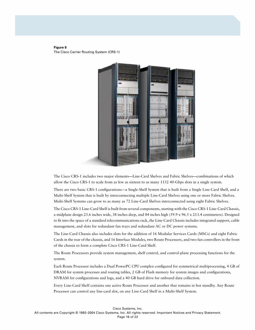
Figure 8
The Cisco Carrier Routing System (CRS-1)
The Cisco CRS-1 includes two major elements—Line-Card Shelves and Fabric Shelves—combinations of which
allow the Cisco CRS-1 to scale from as few as sixteen to as many 1152 40-Gbps slots in a single system.
There are two basic CRS-1 configurations—a Single-Shelf System that is built from a Single Line-Card Shelf, and a
Multi-Shelf System that is built by interconnecting multiple Line-Card Shelves using one or more Fabric Shelves.
Multi-Shelf Systems can grow to as many as 72 Line-Card Shelves interconnected using eight Fabric Shelves.
The Cisco CRS-1 Line-Card Shelf is built from several components, starting with the Cisco CRS-1 Line-Card Chassis,
a midplane design 23.6 inches wide, 38 inches deep, and 84 inches high (59.9 x 96.5 x 213.4 centimeters). Designed
to fit into the space of a standard telecommunications rack, the Line-Card Chassis includes integrated support, cable
management, and slots for redundant fan trays and redundant AC or DC power systems.
The Line-Card Chassis also includes slots for the addition of 16 Modular Services Cards (MSCs) and eight Fabric
Cards in the rear of the chassis, and 16 Interface Modules, two Route Processors, and two fan controllers in the front
of the chassis to form a complete Cisco CRS-1 Line-Card Shelf.
The Route Processors provide system management, shelf control, and control-plane processing functions for the
system.
Each Route Processor includes a Dual PowerPC CPU complex configured for symmetrical multiprocessing, 4 GB of
DRAM for system processes and routing tables, 2 GB of Flash memory for system images and configurations,
NVRAM for configurations and logs, and a 40 GB hard drive for onboard data collection.
Every Line-Card Shelf contains one active Route Processor and another that remains in hot standby. Any Route
Processor can control any line-card slot, on any Line-Card Shelf in a Multi-Shelf System.
Cisco Systems, Inc.s are Copyright © 1992–2004 Cisco Systems, Inc. All rights reserved. Important Notices and Privacy Statement.
Page 16 of 22
All content
To augment the processing power provided by the Route Processors, the Cisco CRS-1 architecture also includes
support for Distributed Route Processors that provide two additional Dual PowerPC CPU complexes and associated
DRAM. Distributed Route Processors allow the operator to distribute control-plane functions and processing
arbitrarily to meet service separation, performance, or logical routing objectives.
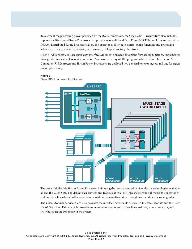
Cisco Modular Services Cards pair with Interface Modules to provide data plane forwarding functions, implemented
through the innovative Cisco Silicon Packet Processor, an array of 188 programmable Reduced Instruction Set
Computer (RISC) processors. Silicon Packet Processors are deployed two per card: one for ingress and one for egress
packet processing.
Figure 9
Cisco CRS-1 Hardware Architecture
The powerful, flexible Silicon Packet Processor, built using the most advanced semiconductor technologies available,
allows the Cisco CRS-1 to deliver rich services and features at true 40-Gbps speeds while allowing the operator to
scale services linearly and offer new features without service disruption through microcode software upgrades.
The Cisco Modular Services Card also provides the interface between its associated Interface Module and the Cisco
CRS-1 Switching Fabric which provides an interconnection to every other line-card slot, Route Processor, and
Distributed Route Processor in the system.
LINE CARD
LINE CARD
MULTI-STAGESWITCH FABRIC
MULTI-STAGESWITCH FABRIC
S1
S1
S2
S2 S3
S3
S1
S1
S2
S2 S3
S3
S1
S1
S2
S2 S3
S3
S1
S1
S2
S2 S3
S3
S1
S1
S2
S2 S3
S3
S1
S1
S2
S2 S3
S3
S1
S1
S2
S2 S3
S3
S1
S1
S2
S2 S3
S3
ROUTEPROCESSORROUTEPROCESSOR
ROUTEPROCESSORROUTEPROCESSOR
ROUTEPROCESSORROUTEPROCESSOR
INTERFACEMODULE
MODULAR SERVICE CARD
MID
PLA
NE
LINE CARD
CISCOSPP
CISCOSPP
Cisco Systems, Inc.s are Copyright © 1992–2004 Cisco Systems, Inc. All rights reserved. Important Notices and Privacy Statement.
Page 17 of 22
All content
The Cisco CRS-1 Interface Modules are modular physical interfaces that are paired with the Cisco Modular Services
Card to form a complete line-card slot. Interface Modules include: OC-768c/STM-256c, OC-192c/STM-64c, OC-
48c/STM-16c, and 10 Gigabit Ethernet.
The Cisco CRS-1 implements a unique, three-stage, dynamically self-routed Benes topology switching fabric to
provide a highly scalable, available, and survivable interconnection between all slots in a Cisco CRS-1 system: from
1 to 1152 slots in a Multi-Shelf System.
The three-stage fabric provides high and low priorities for both unicast and multicast traffic, which is replicated
efficiently by the fabric for up to 1 million groups.
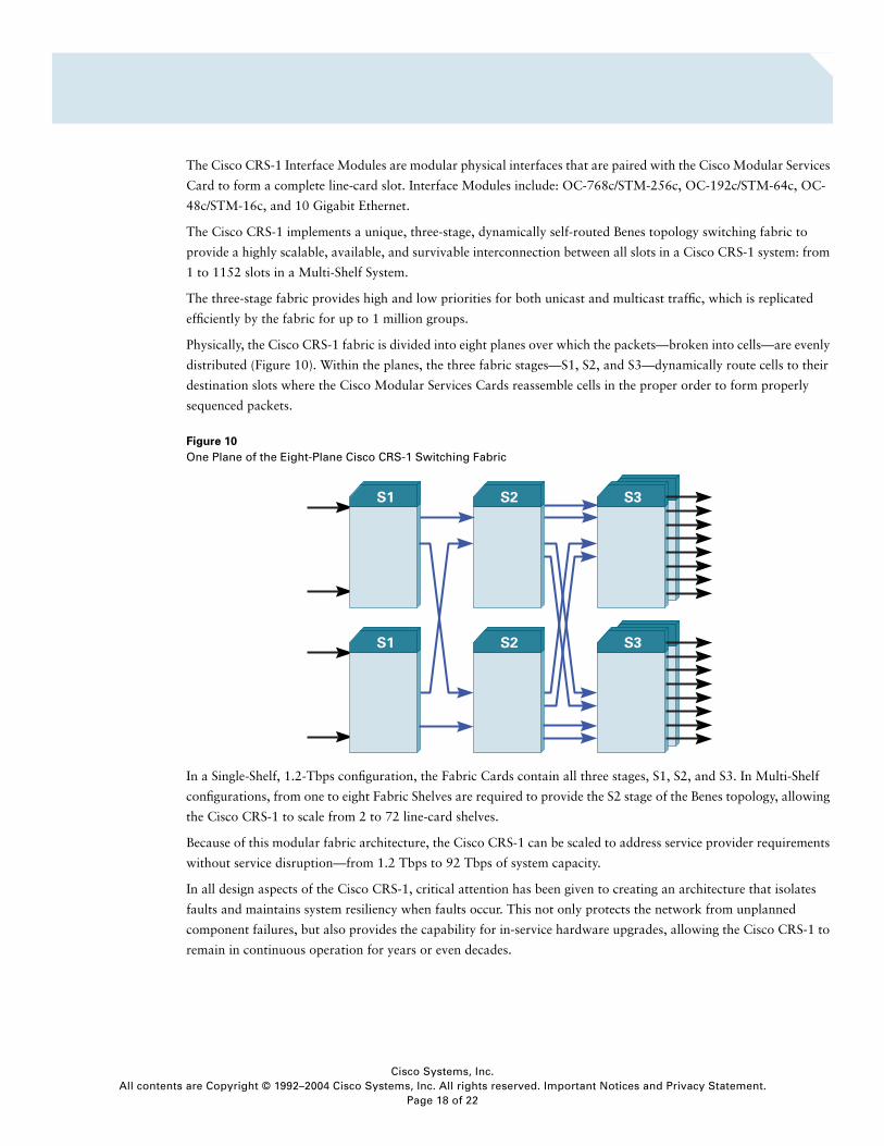
Physically, the Cisco CRS-1 fabric is divided into eight planes over which the packets—broken into cells—are evenly
distributed (Figure 10). Within the planes, the three fabric stages—S1, S2, and S3—dynamically route cells to their
destination slots where the Cisco Modular Services Cards reassemble cells in the proper order to form properly
sequenced packets.
Figure 10
One Plane of the Eight-Plane Cisco CRS-1 Switching Fabric
In a Single-Shelf, 1.2-Tbps configuration, the Fabric Cards contain all three stages, S1, S2, and S3. In Multi-Shelf
configurations, from one to eight Fabric Shelves are required to provide the S2 stage of the Benes topology, allowing
the Cisco CRS-1 to scale from 2 to 72 line-card shelves.
Because of this modular fabric architecture, the Cisco CRS-1 can be scaled to address service provider requirements
without service disruption—from 1.2 Tbps to 92 Tbps of system capacity.
In all design aspects of the Cisco CRS-1, critical attention has been given to creating an architecture that isolates
faults and maintains system resiliency when faults occur. This not only protects the network from unplanned
component failures, but also provides the capability for in-service hardware upgrades, allowing the Cisco CRS-1 to
remain in continuous operation for years or even decades.
Cisco Systems, Inc.s are Copyright © 1992–2004 Cisco Systems, Inc. All rights reserved. Important Notices and Privacy Statement.
Page 18 of 22
All content
INTRODUCING CISCO IOS XR SOFTWARE
To take full advantage of the powerful, distributed hardware architecture of the Cisco CRS-1, Cisco Systems has
developed Cisco IOS® XR Software, a new member of the Cisco IOS Software Family that leverages 20 years of IOS
innovation and development. Cisco IOS XR Software is designed specifically to address the requirements for massive
scalability, continuous system operation, and exceptional service flexibility demanded by converged packet
infrastructures.
Cisco IOS XR Software is the first fully modular, fully distributed internetwork operating system built on a
microkernel-based, memory-protected architecture that strictly segments all operating system components, from
device drivers and file systems to management interfaces and routing protocols, helping to ensure complete process
separation and fault isolation (refer to Figure 11).
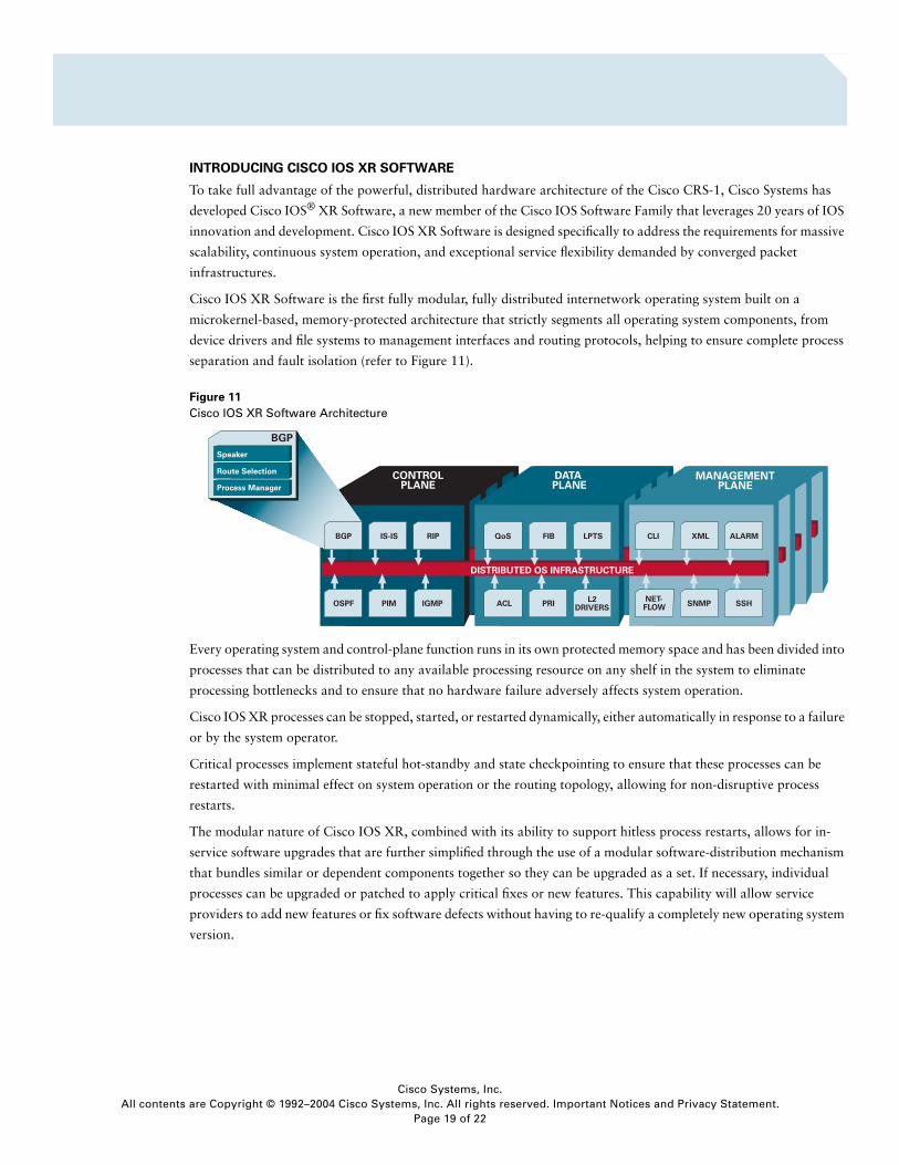
Figure 11
Cisco IOS XR Software Architecture
Every operating system and control-plane function runs in its own protected memory space and has been divided into
processes that can be distributed to any available processing resource on any shelf in the system to eliminate
processing bottlenecks and to ensure that no hardware failure adversely affects system operation.
Cisco IOS XR processes can be stopped, started, or restarted dynamically, either automatically in response to a failure
or by the system operator.
Critical processes implement stateful hot-standby and state checkpointing to ensure that these processes can be
restarted with minimal effect on system operation or the routing topology, allowing for non-disruptive process
restarts.
The modular nature of Cisco IOS XR, combined with its ability to support hitless process restarts, allows for in-
service software upgrades that are further simplified through the use of a modular software-distribution mechanism
that bundles similar or dependent components together so they can be upgraded as a set. If necessary, individual
processes can be upgraded or patched to apply critical fixes or new features. This capability will allow service
providers to add new features or fix software defects without having to re-qualify a completely new operating system
version.
DATAPLANE
Cisco Systems, Inc.s are Copyright © 1992–2004 Cisco Systems, Inc. All rights reserved. Important Notices and Privacy Statement.
Page 19 of 22
All content
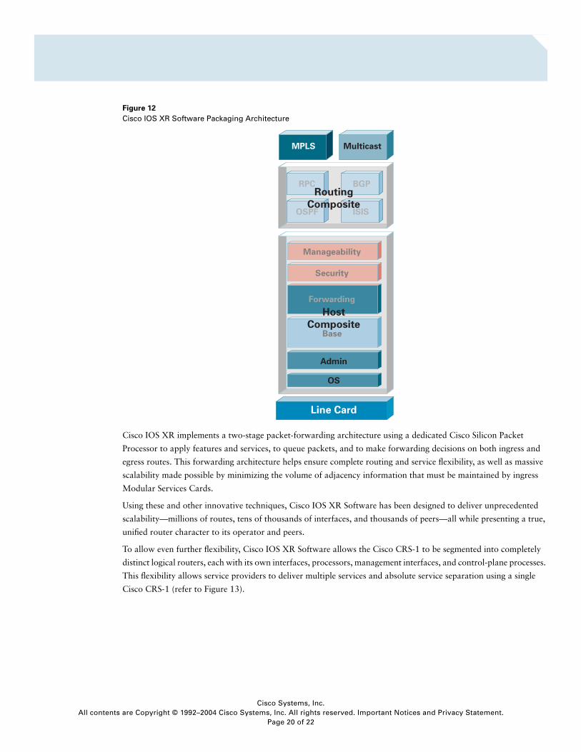
Figure 12
Cisco IOS XR Software Packaging Architecture
Cisco IOS XR implements a two-stage packet-forwarding architecture using a dedicated Cisco Silicon Packet
Processor to apply features and services, to queue packets, and to make forwarding decisions on both ingress and
egress routes. This forwarding architecture helps ensure complete routing and service flexibility, as well as massive
scalability made possible by minimizing the volume of adjacency information that must be maintained by ingress
Modular Services Cards.
Using these and other innovative techniques, Cisco IOS XR Software has been designed to deliver unprecedented
scalability—millions of routes, tens of thousands of interfaces, and thousands of peers—all while presenting a true,
unified router character to its operator and peers.
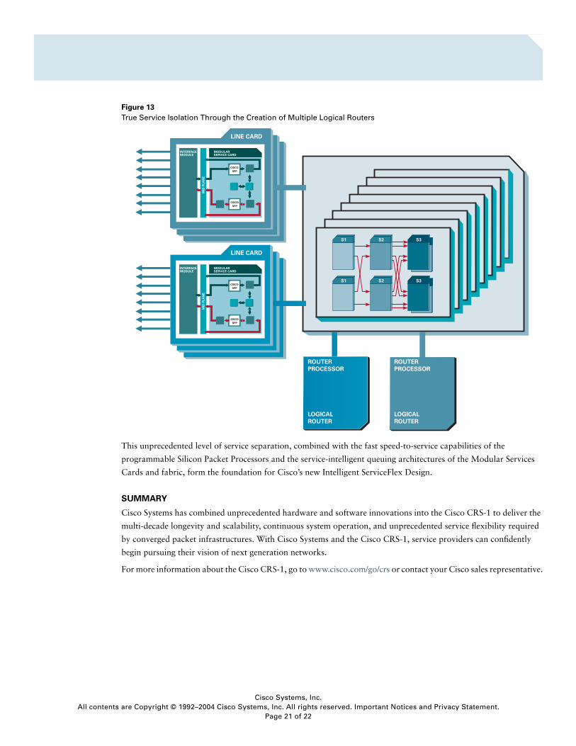
To allow even further flexibility, Cisco IOS XR Software allows the Cisco CRS-1 to be segmented into completely
distinct logical routers, each with its own interfaces, processors, management interfaces, and control-plane processes.
This flexibility allows service providers to deliver multiple services and absolute service separation using a single
Cisco CRS-1 (refer to Figure 13).
RPC BGP
OSPF ISIS
Base
MPLS
Manageability
Security
Forwarding
Multicast
Host
Composite
Routing
Composite
Admin
OS
Line Card
Cisco Systems, Inc.s are Copyright © 1992–2004 Cisco Systems, Inc. All rights reserved. Important Notices and Privacy Statement.
Page 20 of 22
All content
Figure 13
True Service Isolation Through the Creation of Multiple Logical Routers
This unprecedented level of service separation, combined with the fast speed-to-service capabilities of the
programmable Silicon Packet Processors and the service-intelligent queuing architectures of the Modular Services
Cards and fabric, form the foundation for Cisco’s new Intelligent ServiceFlex Design.
SUMMARY
Cisco Systems has combined unprecedented hardware and software innovations into the Cisco CRS-1 to deliver the
multi-decade longevity and scalability, continuous system operation, and unprecedented service flexibility required
by converged packet infrastructures. With Cisco Systems and the Cisco CRS-1, service providers can confidently
begin pursuing their vision of next generation networks.
For more information about the Cisco CRS-1, go to www.cisco.com/go/crs or contact your Cisco sales representative.
Cisco Systems, Inc.s are Copyright © 1992–2004 Cisco Systems, Inc. All rights reserved. Important Notices and Privacy Statement.
Page 21 of 22

Corporate HeadquartersCisco Systems, Inc.170 West Tasman DriveSan Jose, CA 95134-1706USAwww.cisco.comTel: 408 526-4000
800 553-NETS (6387)Fax: 408 526-4100
European HeadquartersCisco Systems International BVHaarlerbergparkHaarlerbergweg 13-191101 CH AmsterdamThe Netherlandswww-europe.cisco.comTel: 31 0 20 357 1000Fax: 31 0 20 357 1100
Americas HeadquartersCisco Systems, Inc.170 West Tasman DriveSan Jose, CA 95134-1706USAwww.cisco.comTel: 408 526-7660Fax: 408 527-0883
Asia Pacific HeadquartersCisco Systems, Inc.168 Robinson Road#28-01 Capital TowerSingapore 068912www.cisco.comTel: +65 6317 7777Fax: +65 6317 7799
Cisco Systems has more than 200 offices in the following countries and regions. Addresses, phone numbers, and fax numbers are listed on the
C i s c o W e b s i t e a t w w w . c i s c o . c o m / g o / o f fi c e s
Argentina • Australia • Austria • Belgium • Brazil • Bulgaria • Canada • Chile • China PRC • Colombia • Costa Rica • Croatia • CyprusCzech Republic • Denmark • Dubai, UAE • Finland • France • Germany • Greece • Hong Kong SAR • Hungary • India • Indonesia • IrelandIsrael • Italy • Japan • Korea • Luxembourg • Malaysia • Mexico • The Netherlands • New Zealand • Norway • Peru • Philippines • PolandPortugal • Puerto Rico • Romania • Russia • Saudi Arabia • Scotland • Singapore • Slovakia • Slovenia • South Africa • Spain • SwedenSwitzer land • Taiwan • Thai land • Turkey • Ukraine • United Kingdom • United States • Venezuela • Vietnam • Zimbabwe
All contents are Copyright © 1992–2004 Cisco Systems, Inc. All rights reserved. Cisco, Cisco IOS, Cisco Systems, and the Cisco Systems logo are registered trademarks of Cisco Systems, Inc. and/or its affiliates in the UnitedStates and certain other countries.
All other trademarks mentioned in this document or Website are the property of their respective owners. The use of the word partner does not imply a partnership relationship between Cisco and any other company.(0403R) 203254_ETMG_MC_05.04