Embed Size (px)
Citation preview
- 1 -
Nissan Altima Hybrid
© 2010 NISSAN NORTH AMERICA, INC. All rights reserved. This document may not be altered without the written permission of NISSAN NORTH AMERICA, INC. Pub. No. DG1E-1H32U0
- 2 -
Foreword .................................................................................................................................................. - 3 - About the Nissan Altima Hybrid .............................................................................................................. - 4 - Altima Hybrid Identification ..................................................................................................................... - 5 - VIN Location .............................................................................................................................................. - 5 - Engine Compartment ................................................................................................................................. - 6 - Exterior ...................................................................................................................................................... - 7 - Interior ....................................................................................................................................................... - 7 - Hybrid System .......................................................................................................................................... - 8 - Component Location and Description ........................................................................................................ - 8 - Battery Information .................................................................................................................................. - 9 - Low Voltage Battery ................................................................................................................................... - 9 - High Voltage Battery .................................................................................................................................. - 9 - Recovery/Recycling of the Ni-MH High Voltage Battery ........................................................................... - 10 - High Voltage Safety ............................................................................................................................... - 11 - High Voltage Safety System ..................................................................................................................... - 11 - Precautions for Dismantling ..................................................................................................................... - 13 - Spills ........................................................................................................................................................ - 13 - First Aid.................................................................................................................................................... - 14 - Vehicle Cut Sheet .................................................................................................................................... - 15 - Dismantling the High Voltage System .................................................................................................. - 16 - Service Disconnect .................................................................................................................................. - 16 - Alternative High Voltage System Shut Down Procedure .......................................................................... - 19 - Removal of HV Battery ............................................................................................................................. - 20 - Removal of HV Components .................................................................................................................... - 22 -
- 3 -
Foreword Nissan released the Altima Hybrid in North America in August of 2007. The Altima Hybrid runs on conventional gasoline and a traction motor. The basic vehicle systems and features of the Altima Hybrid are the same as those of the conventional Altima, except where noted in this guide. This Dismantling Guide was published to help educate and assist the technician in the safe handling of the Altima Hybrid and its technology. A high voltage battery is used to power the traction motor, generator, electric air conditioning compressor, voltage converters, and inverter unit. A separate 12 volt battery is used to power other electrical devices such as the radio, horn, headlamps, and instrument cluster gauges. A number of safeguards have been designed to ensure that the high voltage Nickel Metal Hydride (Ni-MH) battery is kept safe and secure in the event of an accident. The Altima Hybrid utilizes both low and high voltage systems: Low voltage system
A 12 volt DC negative chassis ground body electrical system
High voltage system
A 245 volt DC high voltage battery
A harness that carries high voltage between the high voltage battery, converters, inverter unit, transaxle and electric air conditioning compressor
A converter which converts 245 volts DC to 42 volts DC for the electric power steering (EPS) system
A converter which converts 245 volts DC to 12 volts DC for charging the 12 volt battery
An inverter unit which delivers up to 650 volts AC to the transaxle
A transaxle which houses a traction motor and generator
A 245 volt DC, motor driven electric air conditioning compressor
High voltage electrical safety is an important factor in the dismantling of the Altima Hybrid. It is important to recognize and understand the disabling procedures and warnings throughout this guide.
Additional topics in this guide include:
Nissan Altima Hybrid identification
Hybrid system component locations and descriptions
This Dismantling Guide is intended to assist the technician in the safe handling of a Nissan Altima Hybrid. The information contained in this guide is somewhat simplified and intended to be used as a technical
reference. Please refer to the Nissan Service Manual for information related to vehicle repair.
- 4 -
About the Nissan Altima Hybrid
There are two power sources stored on board that are used to drive the vehicle:
Gasoline is stored in a fuel tank and is used to supply the gasoline engine.
Electricity is stored in a high voltage battery and is used to power the traction motor.
The result of combining these two power sources is improved fuel economy and reduced emissions. The gasoline engine also powers an electric generator to recharge the high voltage battery; unlike an entirely electric vehicle, the Altima Hybrid never needs to be recharged from an external electric power source. Depending on the driving conditions, one or both sources are used to drive the vehicle. The following information explains how the Altima Hybrid operates in various driving modes:
1. During light acceleration at low speeds, the vehicle is driven by the traction motor. The gasoline engine is shut off.
2. During normal driving, the vehicle is driven mainly by the gasoline engine. The gasoline engine also
powers the generator to recharge the high voltage battery.
3. During full acceleration, such as climbing a hill, both the gasoline engine and the traction motor drive the vehicle.
4. During deceleration, such as when braking, the vehicle converts kinetic energy from the front wheels to
electricity that will recharge the high voltage battery.
5. While the vehicle is stopped, such as at a stoplight, both the gasoline engine and the traction motor are off, however the vehicle remains operational.
- 5 -
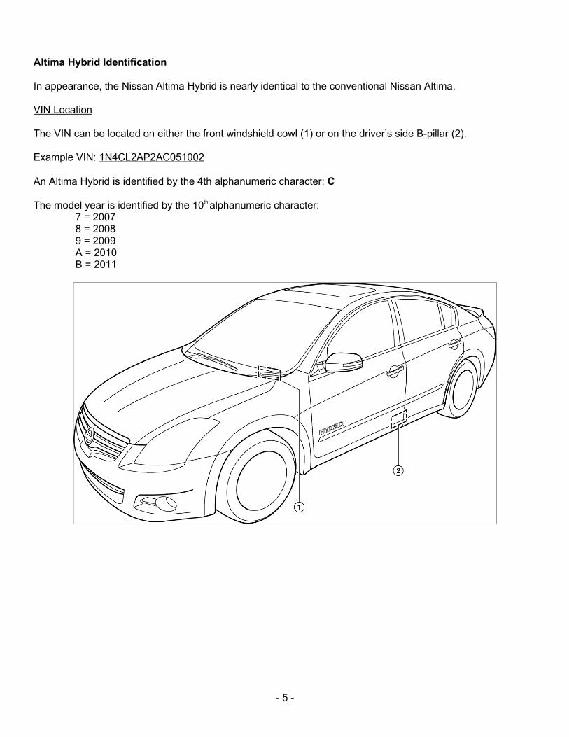
Altima Hybrid Identification
In appearance, the Nissan Altima Hybrid is nearly identical to the conventional Nissan Altima. VIN Location The VIN can be located on either the front windshield cowl (1) or on the driver’s side B-pillar (2). Example VIN: 1N4CL2AP2AC051002
An Altima Hybrid is identified by the 4th alphanumeric character: C
The model year is identified by the 10
th alphanumeric character:
7 = 2007 8 = 2008 9 = 2009 A = 2010 B = 2011
- 6 -
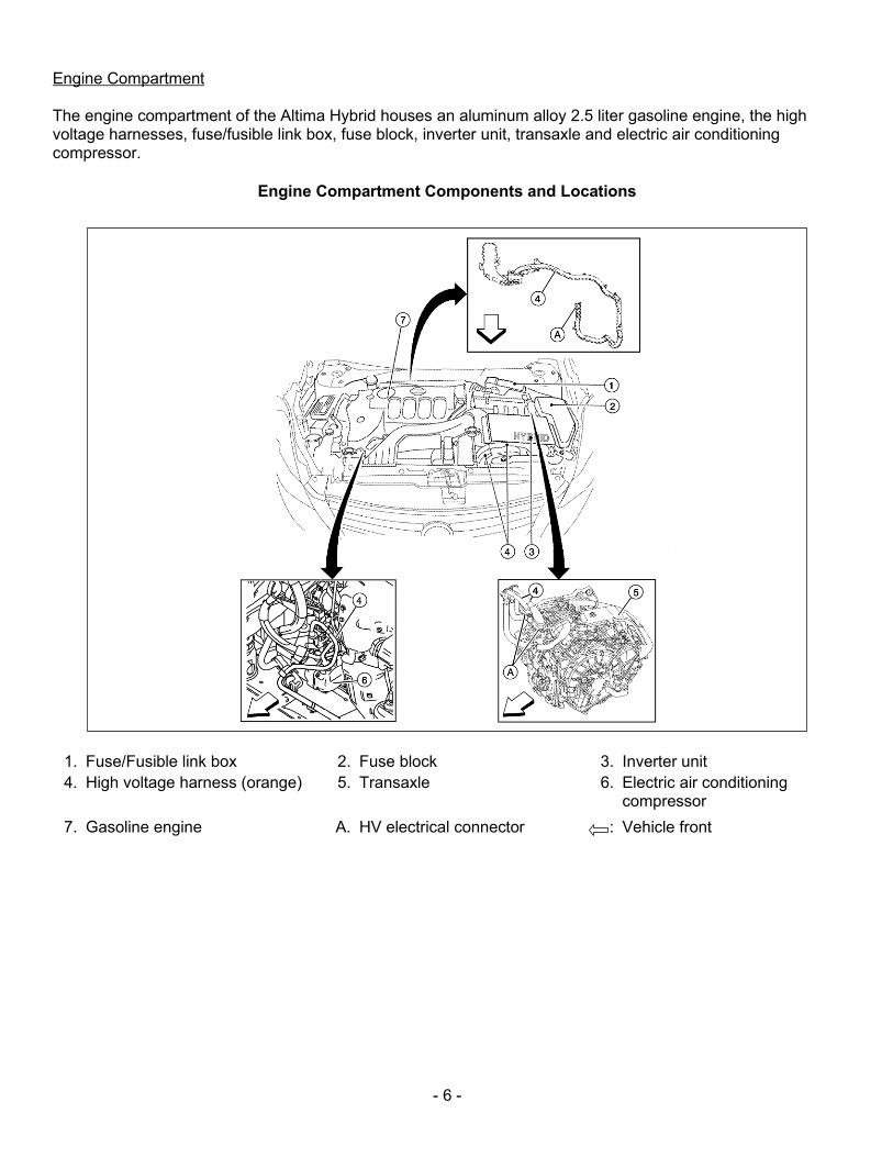
Engine Compartment The engine compartment of the Altima Hybrid houses an aluminum alloy 2.5 liter gasoline engine, the high voltage harnesses, fuse/fusible link box, fuse block, inverter unit, transaxle and electric air conditioning compressor.
Engine Compartment Components and Locations
1. Fuse/Fusible link box 2. Fuse block 3. Inverter unit
4. High voltage harness (orange) 5. Transaxle 6. Electric air conditioning compressor
7. Gasoline engine A. HV electrical connector : Vehicle front
- 7 -
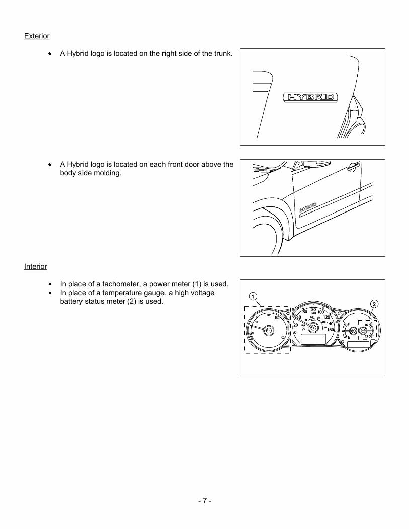
Exterior
A Hybrid logo is located on the right side of the trunk.
A Hybrid logo is located on each front door above the body side molding.
Interior
In place of a tachometer, a power meter (1) is used.
In place of a temperature gauge, a high voltage battery status meter (2) is used.
- 8 -
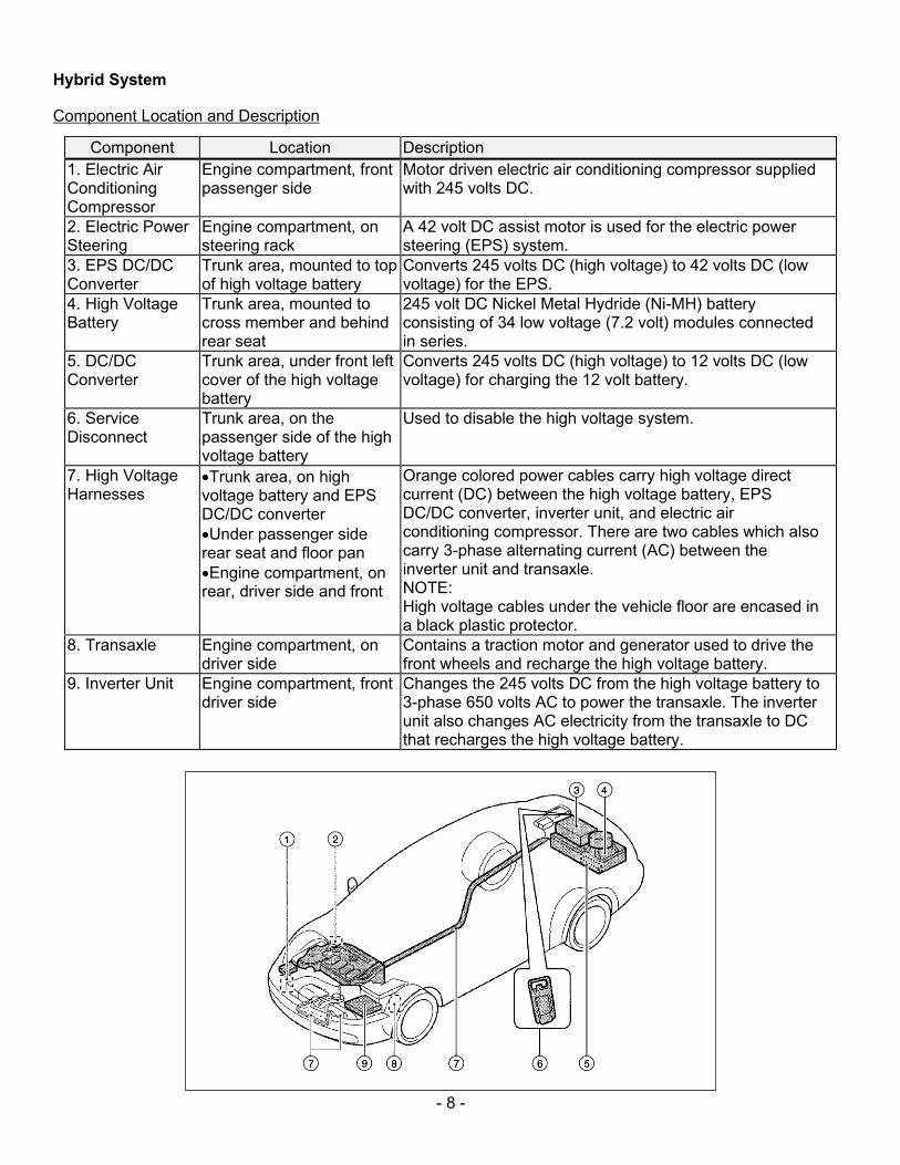
Hybrid System Component Location and Description
Component Location Description
1. Electric Air Conditioning Compressor
Engine compartment, front passenger side
Motor driven electric air conditioning compressor supplied with 245 volts DC.
2. Electric Power Steering
Engine compartment, on steering rack
A 42 volt DC assist motor is used for the electric power steering (EPS) system.
3. EPS DC/DC Converter
Trunk area, mounted to top of high voltage battery
Converts 245 volts DC (high voltage) to 42 volts DC (low voltage) for the EPS.
4. High Voltage Battery
Trunk area, mounted to cross member and behind rear seat
245 volt DC Nickel Metal Hydride (Ni-MH) battery consisting of 34 low voltage (7.2 volt) modules connected in series.
5. DC/DC Converter
Trunk area, under front left cover of the high voltage battery
Converts 245 volts DC (high voltage) to 12 volts DC (low voltage) for charging the 12 volt battery.
6. Service Disconnect
Trunk area, on the passenger side of the high voltage battery
Used to disable the high voltage system.
7. High Voltage Harnesses
Trunk area, on high voltage battery and EPS DC/DC converter
Under passenger side rear seat and floor pan
Engine compartment, on rear, driver side and front
Orange colored power cables carry high voltage direct current (DC) between the high voltage battery, EPS DC/DC converter, inverter unit, and electric air conditioning compressor. There are two cables which also carry 3-phase alternating current (AC) between the inverter unit and transaxle. NOTE: High voltage cables under the vehicle floor are encased in a black plastic protector.
8. Transaxle
Engine compartment, on driver side
Contains a traction motor and generator used to drive the front wheels and recharge the high voltage battery.
9. Inverter Unit Engine compartment, front driver side
Changes the 245 volts DC from the high voltage battery to 3-phase 650 volts AC to power the transaxle. The inverter unit also changes AC electricity from the transaxle to DC that recharges the high voltage battery.
- 9 -
Battery Information
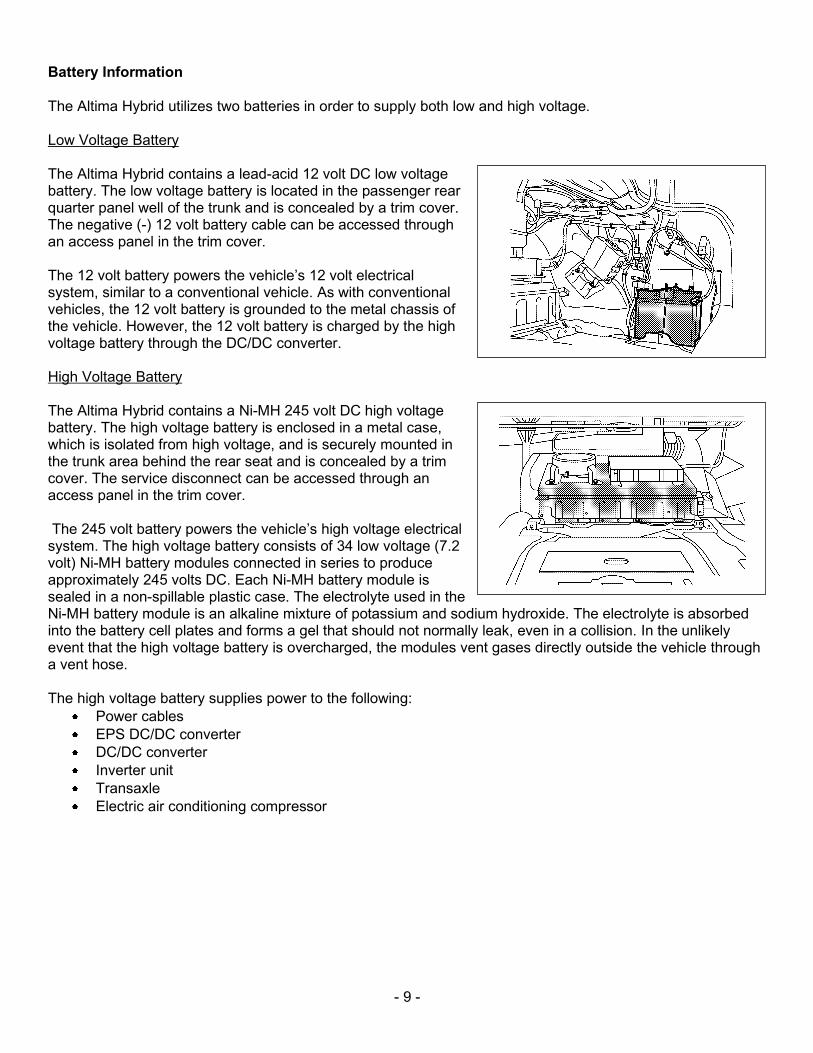
The Altima Hybrid utilizes two batteries in order to supply both low and high voltage. Low Voltage Battery
The Altima Hybrid contains a lead-acid 12 volt DC low voltage battery. The low voltage battery is located in the passenger rear quarter panel well of the trunk and is concealed by a trim cover. The negative (-) 12 volt battery cable can be accessed through an access panel in the trim cover. The 12 volt battery powers the vehicle’s 12 volt electrical system, similar to a conventional vehicle. As with conventional vehicles, the 12 volt battery is grounded to the metal chassis of the vehicle. However, the 12 volt battery is charged by the high voltage battery through the DC/DC converter. High Voltage Battery The Altima Hybrid contains a Ni-MH 245 volt DC high voltage battery. The high voltage battery is enclosed in a metal case, which is isolated from high voltage, and is securely mounted in the trunk area behind the rear seat and is concealed by a trim cover. The service disconnect can be accessed through an access panel in the trim cover. The 245 volt battery powers the vehicle’s high voltage electrical system. The high voltage battery consists of 34 low voltage (7.2 volt) Ni-MH battery modules connected in series to produce approximately 245 volts DC. Each Ni-MH battery module is sealed in a non-spillable plastic case. The electrolyte used in the Ni-MH battery module is an alkaline mixture of potassium and sodium hydroxide. The electrolyte is absorbed into the battery cell plates and forms a gel that should not normally leak, even in a collision. In the unlikely event that the high voltage battery is overcharged, the modules vent gases directly outside the vehicle through a vent hose. The high voltage battery supplies power to the following:
Power cables
EPS DC/DC converter
DC/DC converter
Inverter unit
Transaxle
Electric air conditioning compressor
- 10 -
High Voltage Battery Specifications
High voltage battery voltage 245 V
Number of Ni-MH battery modules in the pack 34
Ni-MH battery module voltage 7.2 V
Ni-MH battery module dimensions 5 x 1 x 11 in. (125.5 x 25.1 x 276.1 mm)
Ni-MH module weight 2.2 lbs (1.0 kg)
Ni-MH high voltage battery dimensions 8 x 34 x 19 in. (200.8 x 853.4 x 476.9 mm)
Ni-MH high voltage battery weight 114.6 lbs (52 kg)
Recovery/Recycling of the Ni-MH High Voltage Battery The high voltage battery is recyclable. For information regarding recycling of the high voltage battery, contact the nearest Nissan dealer or Nissan customer assistance at: United States: 1-800-NISSAN-1 (1-800-647-7261) or in Canada: 1-800-387-0122.
- 11 -
DANGER:
The high voltage system may remain powered for up to 10 minutes after the vehicle is shut off.
The high voltage battery retains high voltage at all times.
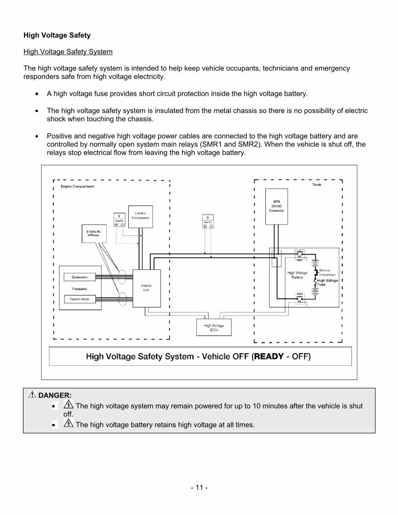
High Voltage Safety High Voltage Safety System The high voltage safety system is intended to help keep vehicle occupants, technicians and emergency responders safe from high voltage electricity.
A high voltage fuse provides short circuit protection inside the high voltage battery.
The high voltage safety system is insulated from the metal chassis so there is no possibility of electric shock when touching the chassis.
Positive and negative high voltage power cables are connected to the high voltage battery and are controlled by normally open system main relays (SMR1 and SMR2). When the vehicle is shut off, the relays stop electrical flow from leaving the high voltage battery.
- 12 -
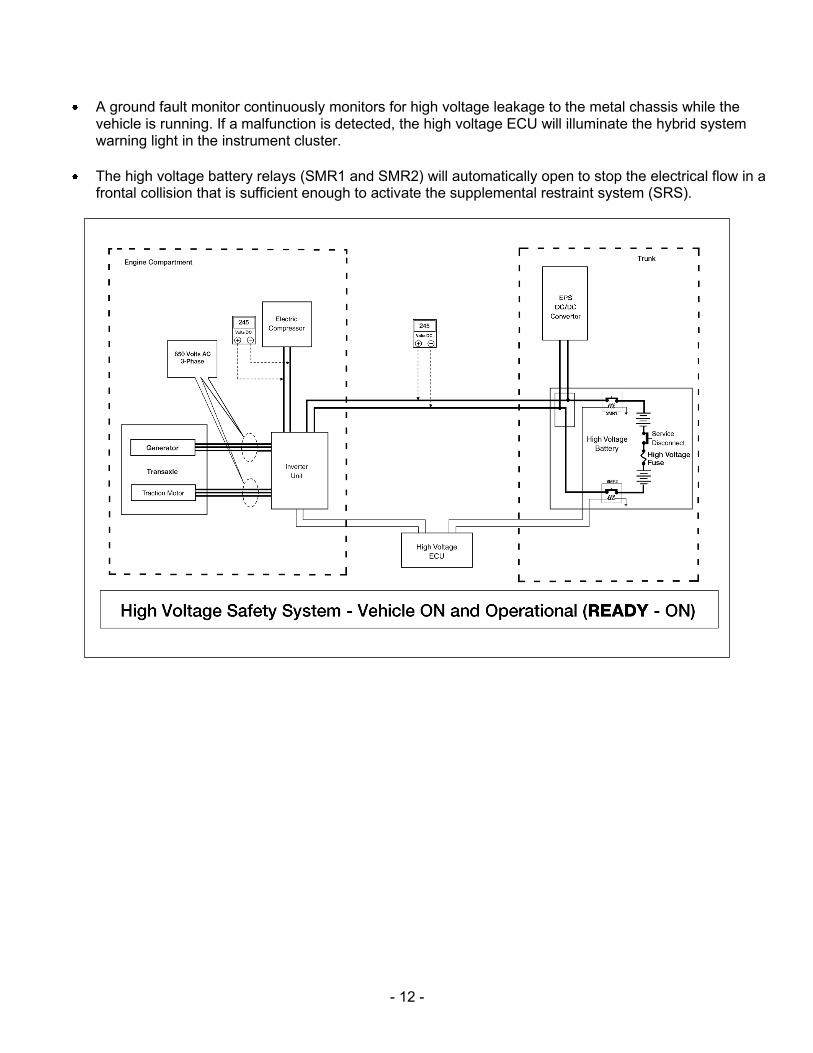
A ground fault monitor continuously monitors for high voltage leakage to the metal chassis while the vehicle is running. If a malfunction is detected, the high voltage ECU will illuminate the hybrid system warning light in the instrument cluster.
The high voltage battery relays (SMR1 and SMR2) will automatically open to stop the electrical flow in a frontal collision that is sufficient enough to activate the supplemental restraint system (SRS).
- 13 -
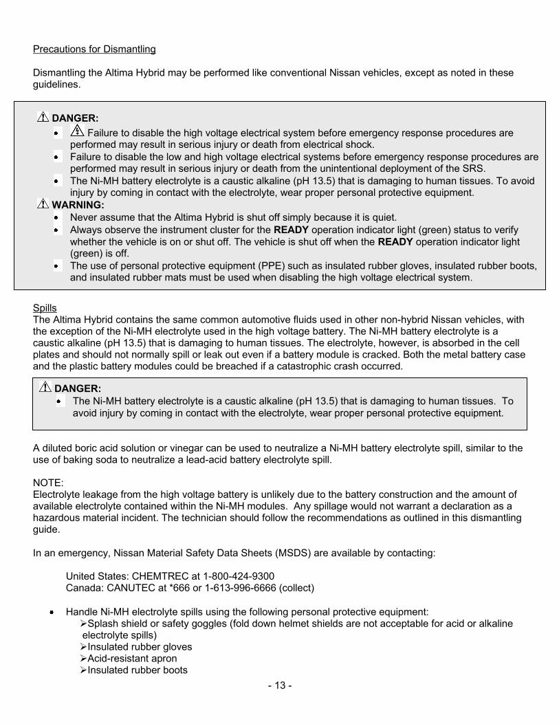
Precautions for Dismantling Dismantling the Altima Hybrid may be performed like conventional Nissan vehicles, except as noted in these guidelines.
Spills The Altima Hybrid contains the same common automotive fluids used in other non-hybrid Nissan vehicles, with the exception of the Ni-MH electrolyte used in the high voltage battery. The Ni-MH battery electrolyte is a caustic alkaline (pH 13.5) that is damaging to human tissues. The electrolyte, however, is absorbed in the cell plates and should not normally spill or leak out even if a battery module is cracked. Both the metal battery case and the plastic battery modules could be breached if a catastrophic crash occurred.
A diluted boric acid solution or vinegar can be used to neutralize a Ni-MH battery electrolyte spill, similar to the use of baking soda to neutralize a lead-acid battery electrolyte spill. NOTE: Electrolyte leakage from the high voltage battery is unlikely due to the battery construction and the amount of available electrolyte contained within the Ni-MH modules. Any spillage would not warrant a declaration as a hazardous material incident. The technician should follow the recommendations as outlined in this dismantling guide.
In an emergency, Nissan Material Safety Data Sheets (MSDS) are available by contacting:
United States: CHEMTREC at 1-800-424-9300 Canada: CANUTEC at *666 or 1-613-996-6666 (collect)
Handle Ni-MH electrolyte spills using the following personal protective equipment: Splash shield or safety goggles (fold down helmet shields are not acceptable for acid or alkaline electrolyte spills) Insulated rubber gloves Acid-resistant apron Insulated rubber boots
DANGER:
Failure to disable the high voltage electrical system before emergency response procedures are performed may result in serious injury or death from electrical shock.
Failure to disable the low and high voltage electrical systems before emergency response procedures are performed may result in serious injury or death from the unintentional deployment of the SRS.
The Ni-MH battery electrolyte is a caustic alkaline (pH 13.5) that is damaging to human tissues. To avoid injury by coming in contact with the electrolyte, wear proper personal protective equipment.
WARNING:
Never assume that the Altima Hybrid is shut off simply because it is quiet.
Always observe the instrument cluster for the READY operation indicator light (green) status to verify
whether the vehicle is on or shut off. The vehicle is shut off when the READY operation indicator light (green) is off.
The use of personal protective equipment (PPE) such as insulated rubber gloves, insulated rubber boots, and insulated rubber mats must be used when disabling the high voltage electrical system.
DANGER:
The Ni-MH battery electrolyte is a caustic alkaline (pH 13.5) that is damaging to human tissues. To
avoid injury by coming in contact with the electrolyte, wear proper personal protective equipment.
- 14 -
Insulated rubber mats (for connect/disconnect of high voltage battery)
Neutralize Ni-MH electrolyte Use a diluted boric acid solution or vinegar. Boric acid solution = 800 grams boric acid to 20 liters water or 5.5 ounces boric acid to 1 gallon of water.
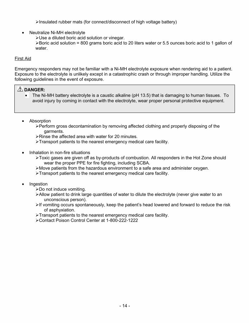
First Aid Emergency responders may not be familiar with a Ni-MH electrolyte exposure when rendering aid to a patient. Exposure to the electrolyte is unlikely except in a catastrophic crash or through improper handling. Utilize the following guidelines in the event of exposure.
Absorption Perform gross decontamination by removing affected clothing and properly disposing of the
garments. Rinse the affected area with water for 20 minutes. Transport patients to the nearest emergency medical care facility.
Inhalation in non-fire situations Toxic gases are given off as by-products of combustion. All responders in the Hot Zone should
wear the proper PPE for fire fighting, including SCBA. Move patients from the hazardous environment to a safe area and administer oxygen. Transport patients to the nearest emergency medical care facility.
Ingestion Do not induce vomiting. Allow patient to drink large quantities of water to dilute the electrolyte (never give water to an
unconscious person). If vomiting occurs spontaneously, keep the patient’s head lowered and forward to reduce the risk
of asphyxiation. Transport patients to the nearest emergency medical care facility. Contact Poison Control Center at 1-800-222-1222
DANGER:
The Ni-MH battery electrolyte is a caustic alkaline (pH 13.5) that is damaging to human tissues. To
avoid injury by coming in contact with the electrolyte, wear proper personal protective equipment.
- 15 -
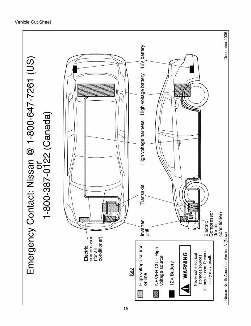
Vehicle Cut Sheet
- 16 -
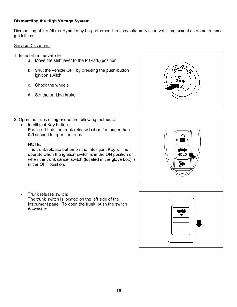
Dismantling the High Voltage System Dismantling of the Altima Hybrid may be performed like conventional Nissan vehicles, except as noted in these guidelines. Service Disconnect 1. Immobilize the vehicle
a. Move the shift lever to the P (Park) position. b. Shut the vehicle OFF by pressing the push-button
ignition switch.
c. Chock the wheels.
d. Set the parking brake. 2. Open the trunk using one of the following methods:
Intelligent Key button: Push and hold the trunk release button for longer than 0.5 second to open the trunk. NOTE: The trunk release button on the Intelligent Key will not operate when the ignition switch is in the ON position or when the trunk cancel switch (located in the glove box) is in the OFF position.
Trunk release switch: The trunk switch is located on the left side of the instrument panel. To open the trunk, push the switch downward.
- 17 -
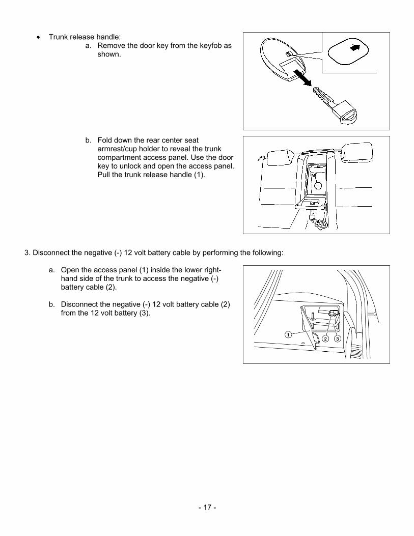
Trunk release handle: a. Remove the door key from the keyfob as
shown.
b. Fold down the rear center seat
armrest/cup holder to reveal the trunk compartment access panel. Use the door key to unlock and open the access panel. Pull the trunk release handle (1).
3. Disconnect the negative (-) 12 volt battery cable by performing the following:
a. Open the access panel (1) inside the lower right-hand side of the trunk to access the negative (-) battery cable (2).
b. Disconnect the negative (-) 12 volt battery cable (2)
from the 12 volt battery (3).
- 18 -
DANGER:
The high voltage system may remain powered for up to 10 minutes after the vehicle is disabled.
To prevent serious injury or death from electrical shock avoid touching, cutting, or breaching any orange high voltage power cable or high voltage component while the system discharges.
WARNING:
The SRS may remain powered for up to 3 minutes after the vehicle is disabled.
To prevent serious injury or death from unintentional SRS deployment, avoid crushing, cutting, or breaching the SRS components.
If the disabling procedures cannot be performed completely, proceed with caution as there is no
assurance that the high voltage electrical system, SRS, or fuel pump are disabled.
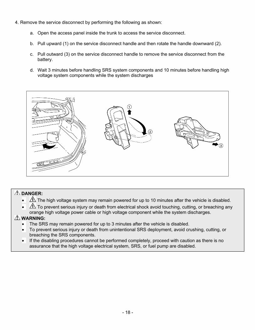
4. Remove the service disconnect by performing the following as shown:
a. Open the access panel inside the trunk to access the service disconnect. b. Pull upward (1) on the service disconnect handle and then rotate the handle downward (2).
c. Pull outward (3) on the service disconnect handle to remove the service disconnect from the
battery.
d. Wait 3 minutes before handling SRS system components and 10 minutes before handling high voltage system components while the system discharges
- 19 -
DANGER:
The high voltage system may remain powered for up to 10 minutes after the vehicle is disabled.
To prevent serious injury or death from electrical shock avoid touching, cutting, or breaching any orange high voltage power cable or high voltage component while the system discharges.
WARNING:
The SRS may remain powered for up to 3 minutes after the vehicle is disabled.
To prevent serious injury or death from unintentional SRS deployment, avoid crushing, cutting, or breaching the SRS components.
If the disabling procedures cannot be performed completely, proceed with caution as there is no
assurance that the high voltage electrical system, SRS, or fuel pump are disabled.
Alternative High Voltage System Shut Down Procedure NOTE: If the service disconnect procedure cannot be performed, the following alternative shut down procedure is acceptable.
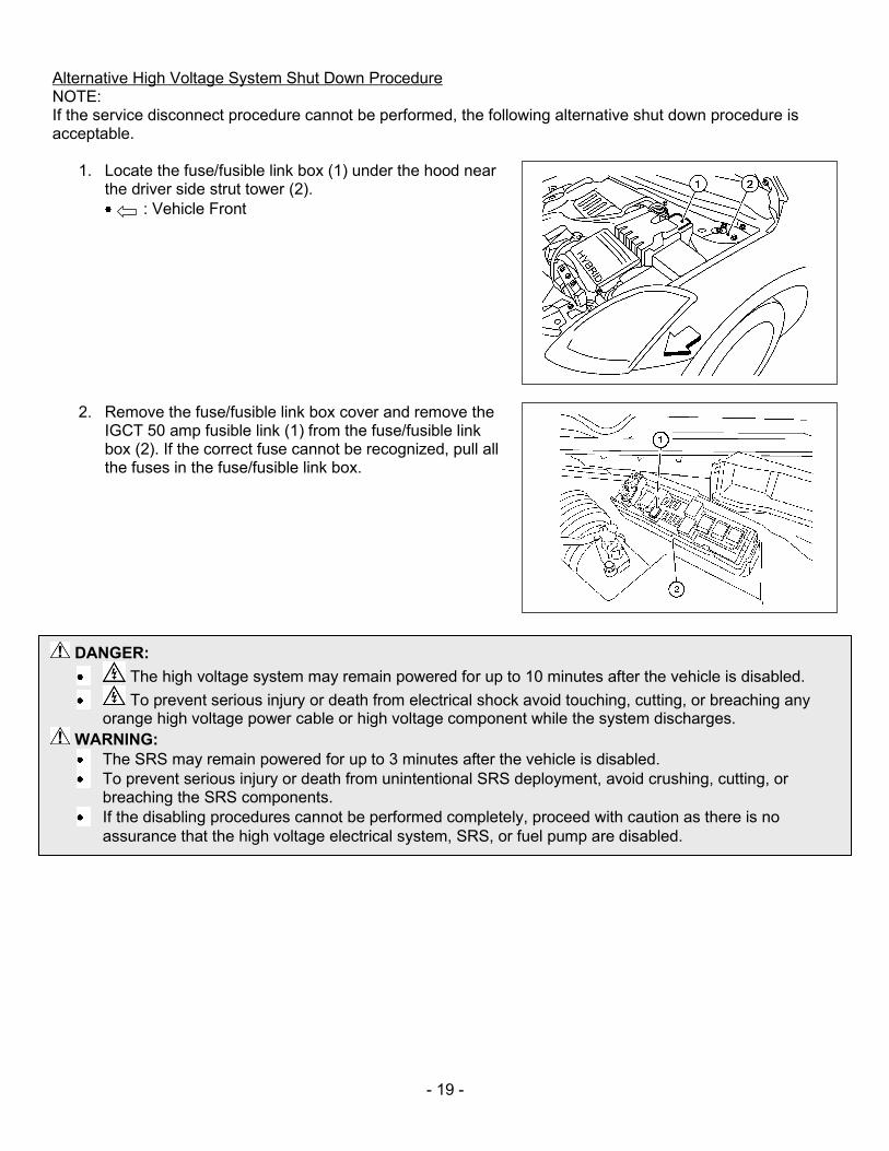
1. Locate the fuse/fusible link box (1) under the hood near the driver side strut tower (2).
: Vehicle Front
2. Remove the fuse/fusible link box cover and remove the IGCT 50 amp fusible link (1) from the fuse/fusible link box (2). If the correct fuse cannot be recognized, pull all the fuses in the fuse/fusible link box.
- 20 -
Removal of HV Battery
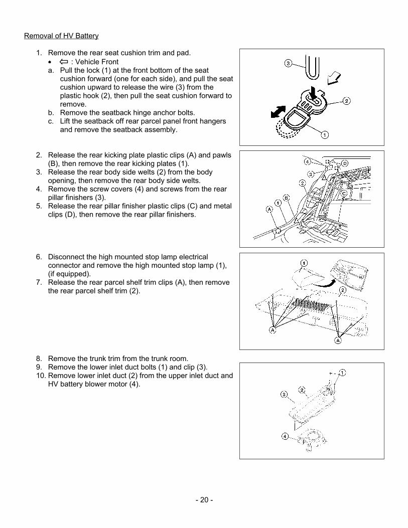
1. Remove the rear seat cushion trim and pad.
: Vehicle Front a. Pull the lock (1) at the front bottom of the seat
cushion forward (one for each side), and pull the seat cushion upward to release the wire (3) from the plastic hook (2), then pull the seat cushion forward to remove.
b. Remove the seatback hinge anchor bolts. c. Lift the seatback off rear parcel panel front hangers
and remove the seatback assembly.
2. Release the rear kicking plate plastic clips (A) and pawls (B), then remove the rear kicking plates (1).
3. Release the rear body side welts (2) from the body opening, then remove the rear body side welts.
4. Remove the screw covers (4) and screws from the rear pillar finishers (3).
5. Release the rear pillar finisher plastic clips (C) and metal clips (D), then remove the rear pillar finishers.
6. Disconnect the high mounted stop lamp electrical connector and remove the high mounted stop lamp (1), (if equipped).
7. Release the rear parcel shelf trim clips (A), then remove the rear parcel shelf trim (2).
8. Remove the trunk trim from the trunk room. 9. Remove the lower inlet duct bolts (1) and clip (3). 10. Remove lower inlet duct (2) from the upper inlet duct and
HV battery blower motor (4).
- 21 -
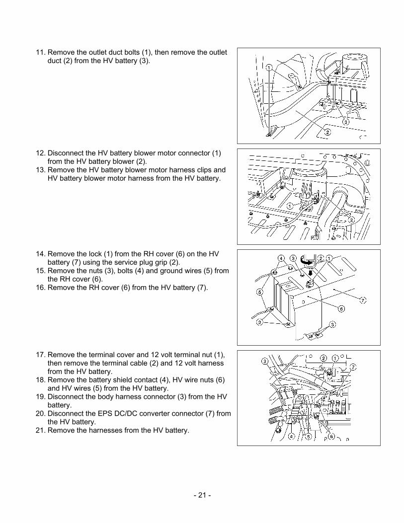
11. Remove the outlet duct bolts (1), then remove the outlet duct (2) from the HV battery (3).
12. Disconnect the HV battery blower motor connector (1) from the HV battery blower (2).
13. Remove the HV battery blower motor harness clips and HV battery blower motor harness from the HV battery.
14. Remove the lock (1) from the RH cover (6) on the HV battery (7) using the service plug grip (2).
15. Remove the nuts (3), bolts (4) and ground wires (5) from the RH cover (6).
16. Remove the RH cover (6) from the HV battery (7).
17. Remove the terminal cover and 12 volt terminal nut (1),
then remove the terminal cable (2) and 12 volt harness from the HV battery.
18. Remove the battery shield contact (4), HV wire nuts (6) and HV wires (5) from the HV battery.
19. Disconnect the body harness connector (3) from the HV battery.
20. Disconnect the EPS DC/DC converter connector (7) from the HV battery.
21. Remove the harnesses from the HV battery.
- 22 -
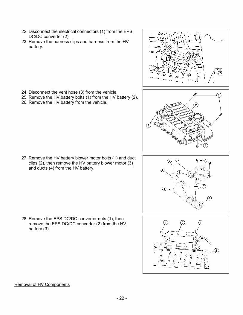
22. Disconnect the electrical connectors (1) from the EPS DC/DC converter (2).
23. Remove the harness clips and harness from the HV battery.
24. Disconnect the vent hose (3) from the vehicle. 25. Remove the HV battery bolts (1) from the HV battery (2). 26. Remove the HV battery from the vehicle.
27. Remove the HV battery blower motor bolts (1) and duct clips (2), then remove the HV battery blower motor (3) and ducts (4) from the HV battery.
28. Remove the EPS DC/DC converter nuts (1), then
remove the EPS DC/DC converter (2) from the HV battery (3).
Removal of HV Components

- 23 -
Dismantling the remainder of the Nissan Altima Hybrid may be performed like conventional Nissan vehicles once the HV system is disabled.