Embed Size (px)
Citation preview
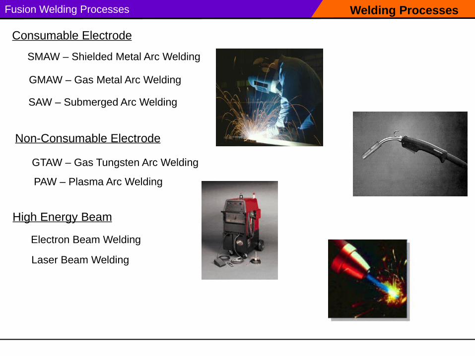
Welding ProcessesFusion Welding Processes
GMAW – Gas Metal Arc Welding
SMAW – Shielded Metal Arc Welding
Non-Consumable Electrode
GTAW – Gas Tungsten Arc Welding
Electron Beam Welding
SAW – Submerged Arc Welding
Consumable Electrode
PAW – Plasma Arc Welding
High Energy Beam
Laser Beam Welding
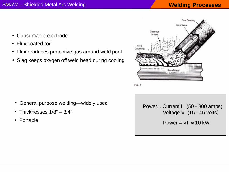
Welding ProcessesSMAW – Shielded Metal Arc Welding
• Slag keeps oxygen off weld bead during cooling
• Consumable electrode
• Flux produces protective gas around weld pool
• Flux coated rod
Power = VI 10 kW
Power... Current I (50 - 300 amps)Voltage V (15 - 45 volts)
• General purpose welding—widely used
• Thicknesses 1/8” – 3/4”
• Portable
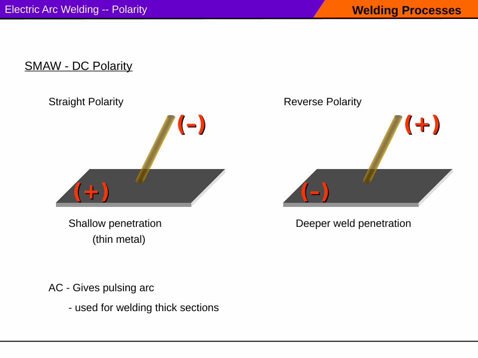
Welding ProcessesElectric Arc Welding -- Polarity
SMAW - DC Polarity
Straight Polarity
Shallow penetration Deeper weld penetration
(thin metal)
Reverse Polarity
(+)(+)
(–)(–)
(–)(–)
(+)(+)
AC - Gives pulsing arc
- used for welding thick sections
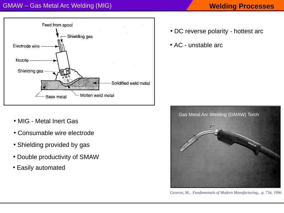
Welding ProcessesGMAW – Gas Metal Arc Welding (MIG)
• DC reverse polarity - hottest arc
• MIG - Metal Inert Gas
• Consumable wire electrode
• AC - unstable arc
Groover, M., Fundamentals of Modern Manufacturing,, p. 734, 1996
Gas Metal Arc Welding (GMAW) Torch
• Shielding provided by gas
• Double productivity of SMAW
• Easily automated
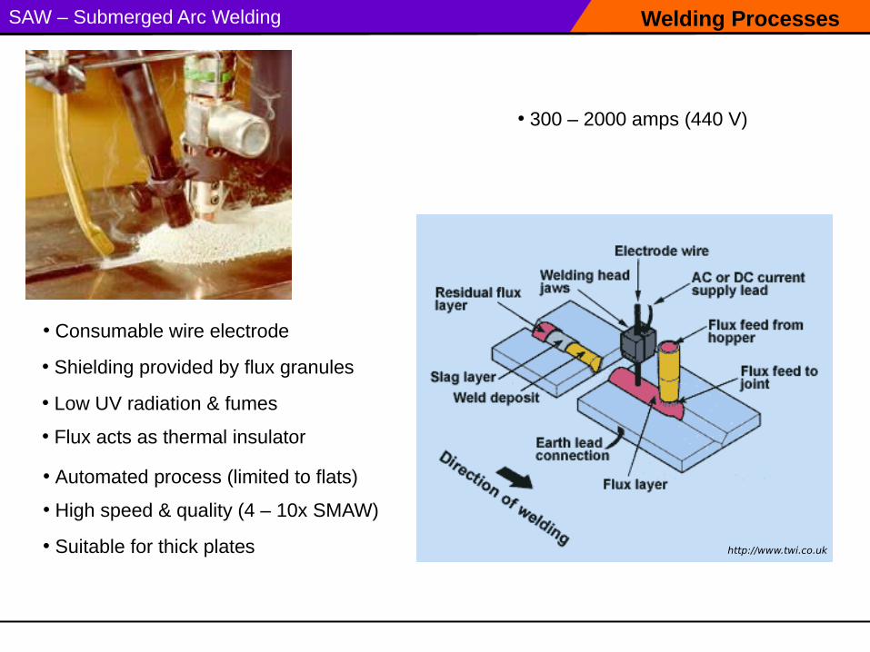
Welding ProcessesSAW – Submerged Arc Welding
• 300 – 2000 amps (440 V)
• Consumable wire electrodeGas Metal Arc Welding (GMAW) Torch
• Shielding provided by flux granules
• Automated process (limited to flats)
• Low UV radiation & fumes
• Flux acts as thermal insulator
• High speed & quality (4 – 10x SMAW)
• Suitable for thick plates http://www.twi.co.uk
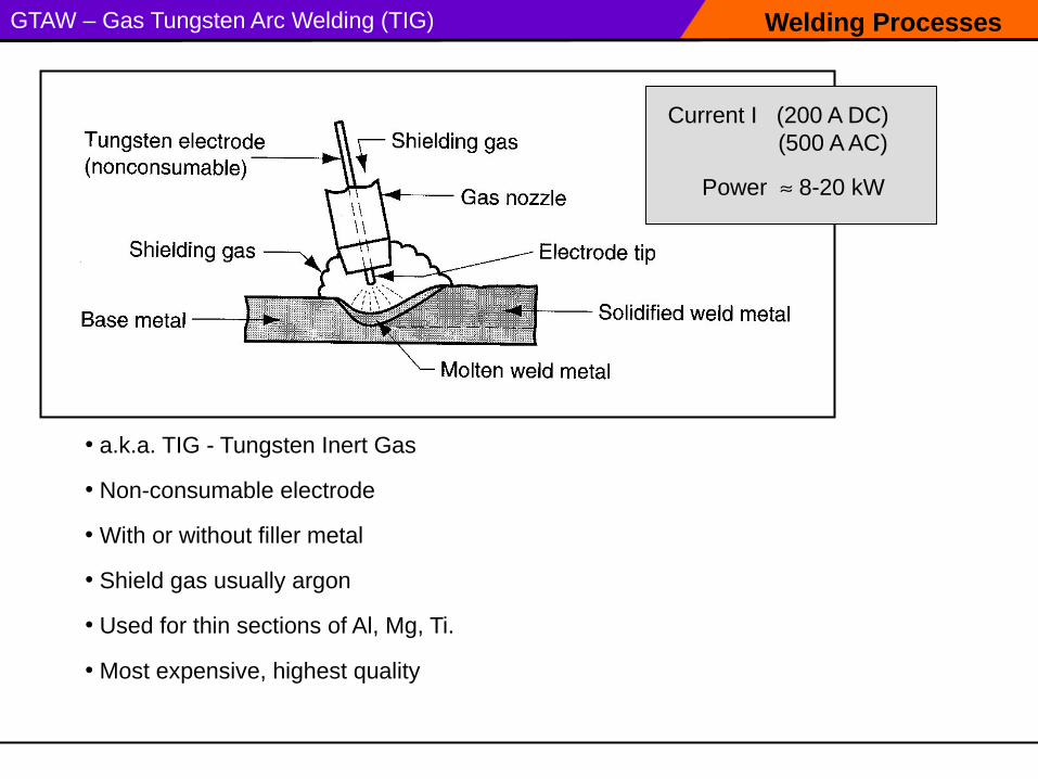
Welding ProcessesGTAW – Gas Tungsten Arc Welding (TIG)
• Non-consumable electrode
• a.k.a. TIG - Tungsten Inert Gas
• Shield gas usually argon
• Used for thin sections of Al, Mg, Ti.
• With or without filler metal
Power 8-20 kW
Current I (200 A DC) (500 A AC)
• Most expensive, highest quality
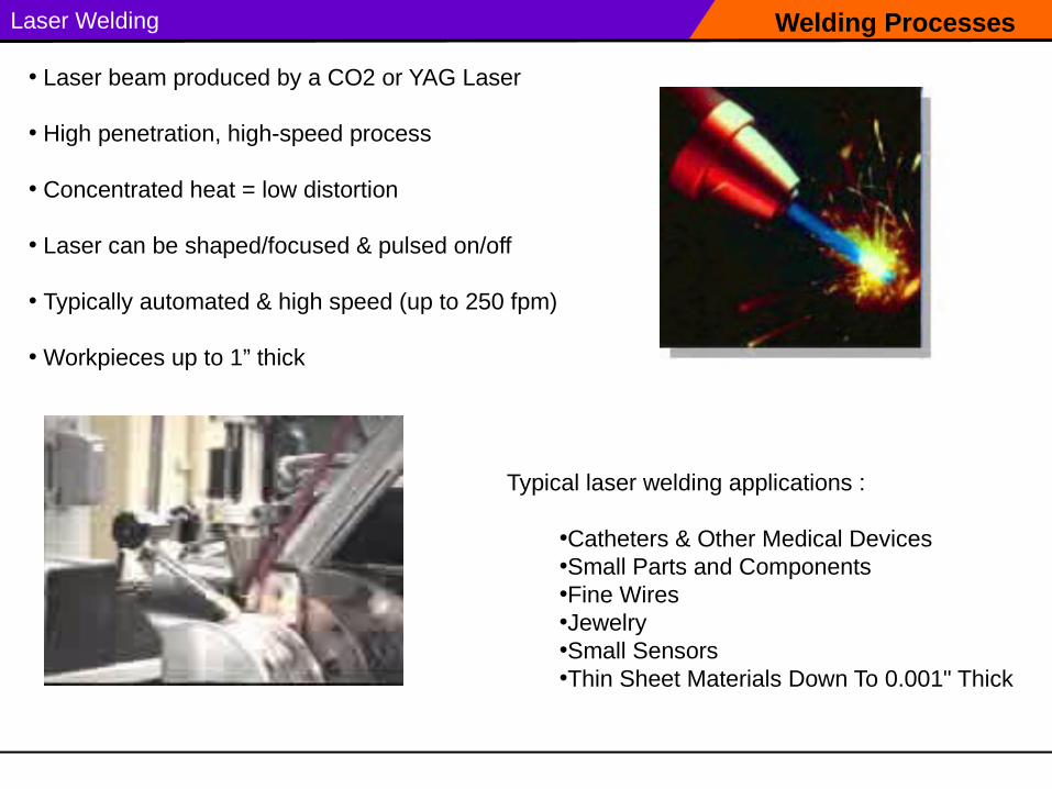
Welding ProcessesLaser Welding
Typical laser welding applications :
•Catheters & Other Medical Devices •Small Parts and Components •Fine Wires •Jewelry •Small Sensors •Thin Sheet Materials Down To 0.001" Thick
• Laser beam produced by a CO2 or YAG Laser
• High penetration, high-speed process
• Concentrated heat = low distortion
• Laser can be shaped/focused & pulsed on/off
• Typically automated & high speed (up to 250 fpm)
• Workpieces up to 1” thick
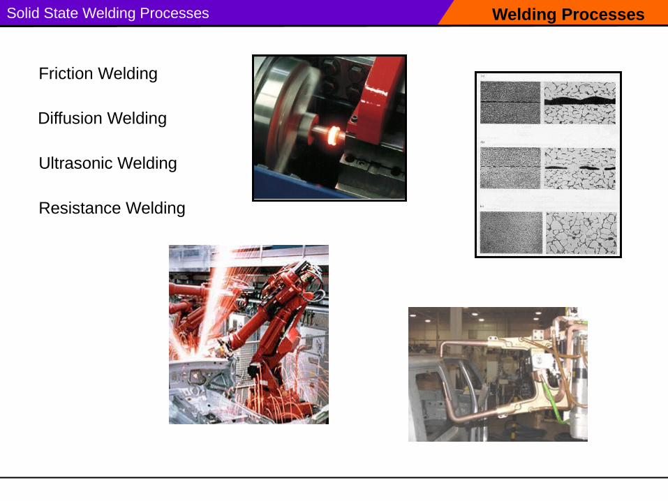
Welding ProcessesSolid State Welding Processes
Friction Welding
Ultrasonic Welding
Resistance Welding
Diffusion Welding
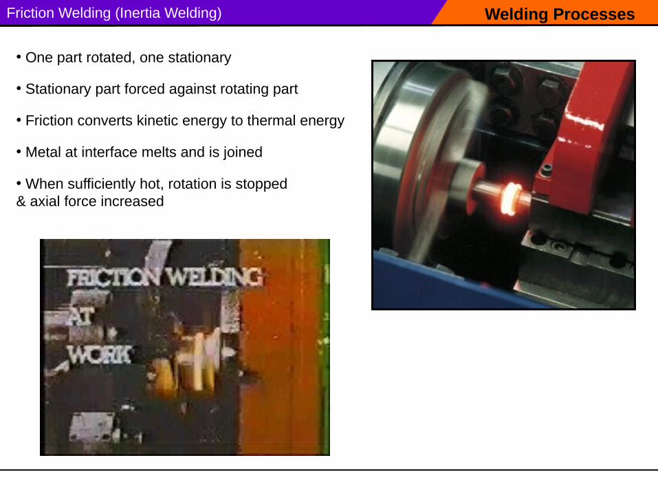
Welding ProcessesFriction Welding (Inertia Welding)
• One part rotated, one stationary
• Stationary part forced against rotating part
• Friction converts kinetic energy to thermal energy
• Metal at interface melts and is joined
• When sufficiently hot, rotation is stopped & axial force increased
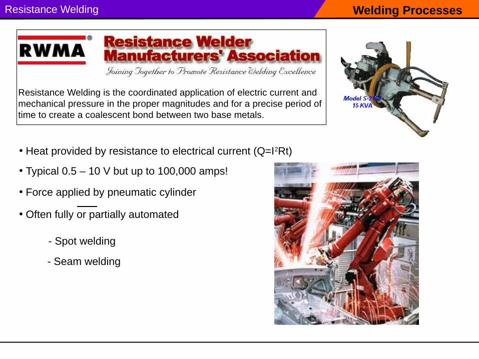
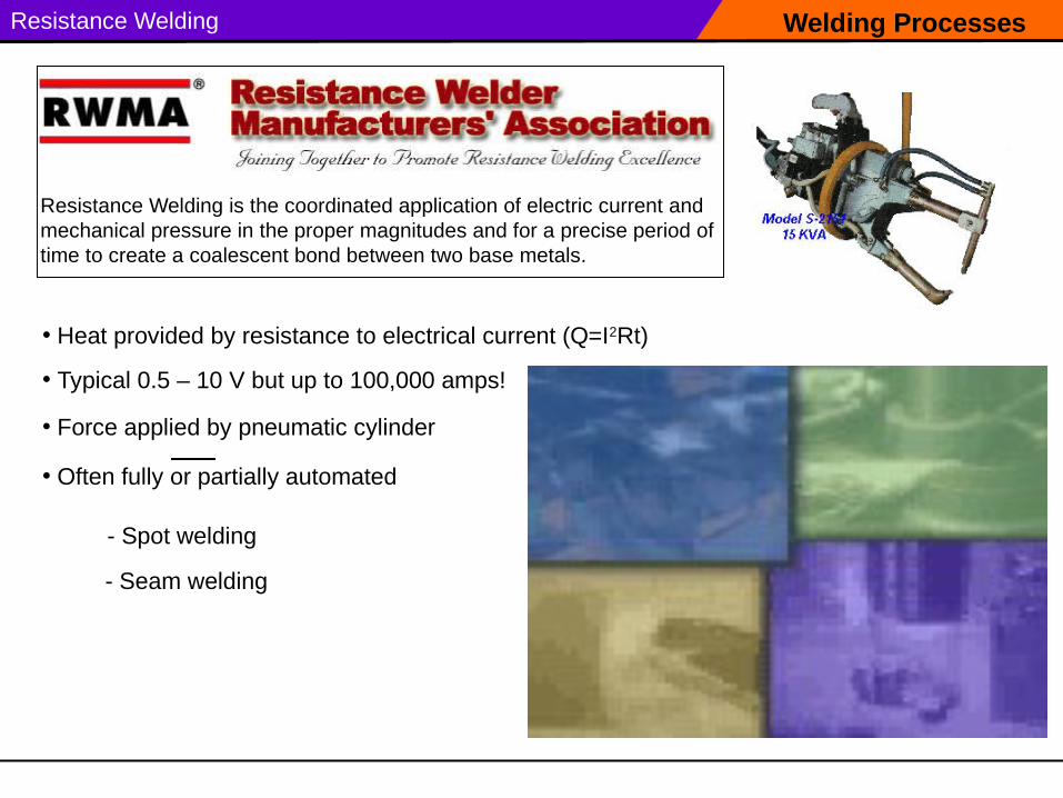
Welding ProcessesResistance Welding
Resistance Welding is the coordinated application of electric current and mechanical pressure in the proper magnitudes and for a precise period of time to create a coalescent bond between two base metals.
• Heat provided by resistance to electrical current (Q=I2Rt)
• Force applied by pneumatic cylinder
• Typical 0.5 – 10 V but up to 100,000 amps!
• Often fully or partially automated
- Spot welding
- Seam welding
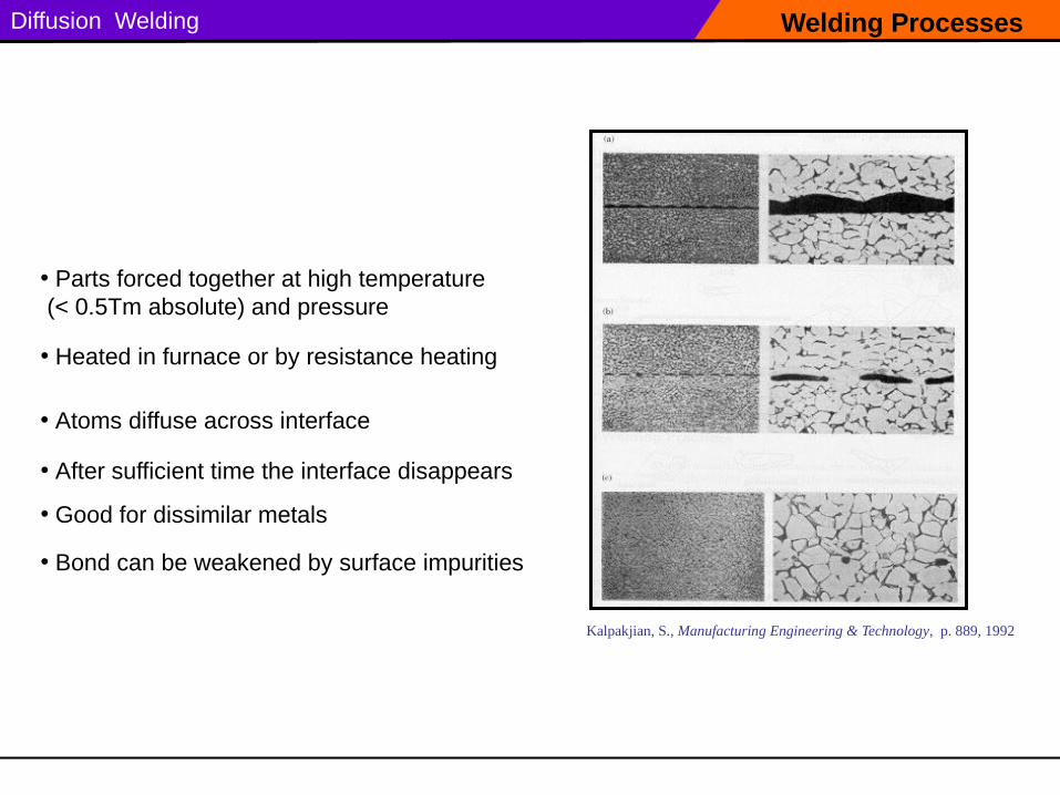
Welding ProcessesDiffusion Welding
• Parts forced together at high temperature (< 0.5Tm absolute) and pressure
Kalpakjian, S., Manufacturing Engineering & Technology, p. 889, 1992
• Atoms diffuse across interface
• After sufficient time the interface disappears
• Good for dissimilar metals
• Heated in furnace or by resistance heating
• Bond can be weakened by surface impurities
Soldering & Brazing Metal Joining Processes
Soldering & Brazing
• Filler metal distributed by capillary action
• Only filler metal is melted, not base metal
• Strength of joint typically
– Can join dissimilar metals
– Less heat - can join thinner sections (relative to welding)
– stronger than filler metal itself
– weaker than base metal
– Excessive heat during service can weaken joint
• Pros & Cons
• Lower temperatures than welding
– gap at joint important (0.001 – 0.010”)
• Metallurgical bond formed between filler & base metals
Soldering
Solder = Filler metal
Metal Joining Processes
Soldering
Applications:
• Printed Circuit Board (PCB) manufacture
• Pipe joining (copper pipe)
• Jewelry manufacture
Easy to solder: copper, silver, gold
Difficult to solder: aluminum, stainless steels
(can pre-plate difficult to solder metals to aid process)
• Alloys of Tin (silver, bismuth, lead)
• Melt point typically below 840 F
Flux used to clean joint & prevent oxidation
• Typically non-load bearing
Tinning = pre-coating with thin layer of solder
• separate or in core of wire (rosin-core)
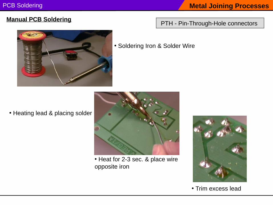
PCB Soldering
• Soldering Iron & Solder Wire
Metal Joining Processes
Manual PCB Soldering
• Heating lead & placing solder
• Trim excess lead
• Heat for 2-3 sec. & place wire opposite iron
PTH - Pin-Through-Hole connectors
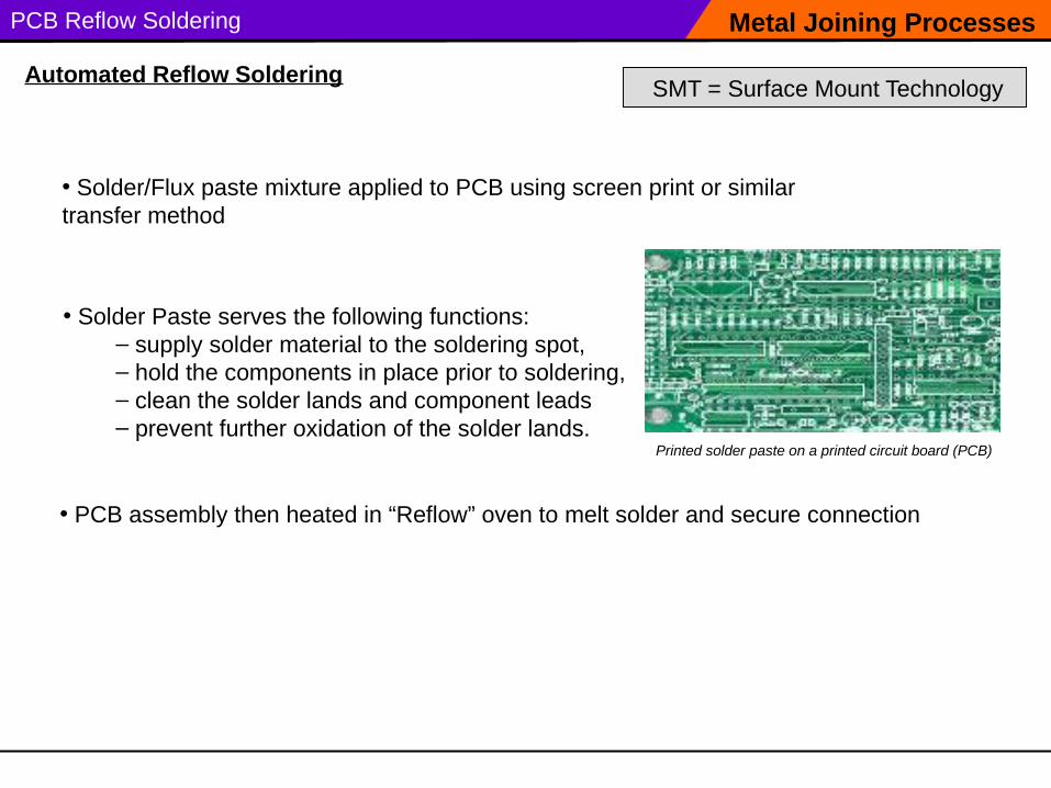
PCB Reflow Soldering Metal Joining Processes
Automated Reflow Soldering SMT = Surface Mount Technology
Printed solder paste on a printed circuit board (PCB)
• Solder Paste serves the following functions:– supply solder material to the soldering spot, – hold the components in place prior to soldering, – clean the solder lands and component leads – prevent further oxidation of the solder lands.
• Solder/Flux paste mixture applied to PCB using screen print or similar transfer method
• PCB assembly then heated in “Reflow” oven to melt solder and secure connection
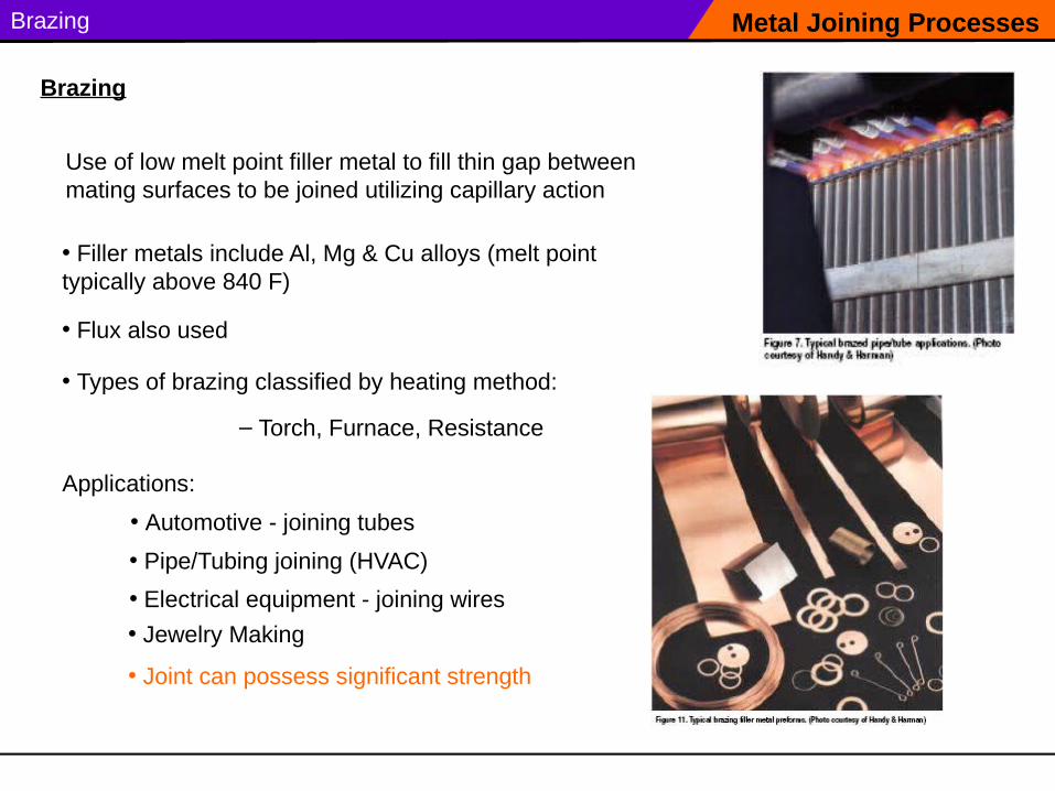
Brazing
Use of low melt point filler metal to fill thin gap between mating surfaces to be joined utilizing capillary action
Metal Joining Processes
Brazing
Applications:
• Pipe/Tubing joining (HVAC)
• Filler metals include Al, Mg & Cu alloys (melt point typically above 840 F)
• Automotive - joining tubes
• Electrical equipment - joining wires
• Jewelry Making
• Flux also used
• Types of brazing classified by heating method:
– Torch, Furnace, Resistance
• Joint can possess significant strength
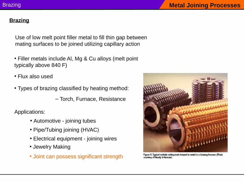
Brazing
Use of low melt point filler metal to fill thin gap between mating surfaces to be joined utilizing capillary action
Metal Joining Processes
Brazing
Applications:
• Pipe/Tubing joining (HVAC)
• Filler metals include Al, Mg & Cu alloys (melt point typically above 840 F)
• Automotive - joining tubes
• Electrical equipment - joining wires
• Jewelry Making
• Flux also used
• Types of brazing classified by heating method:
– Torch, Furnace, Resistance
• Joint can possess significant strength
Brazing Metal Joining Processes
Brazing
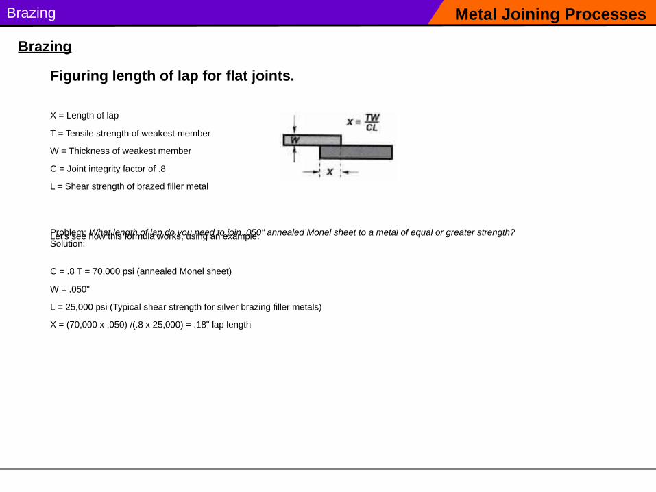
Figuring length of lap for flat joints.
X = Length of lap
T = Tensile strength of weakest member
W = Thickness of weakest member
C = Joint integrity factor of .8
L = Shear strength of brazed filler metal
Let’s see how this formula works, using an example.Problem: What length of lap do you need to join .050" annealed Monel sheet to a metal of equal or greater strength? Solution:
C = .8 T = 70,000 psi (annealed Monel sheet)
W = .050"
L = 25,000 psi (Typical shear strength for silver brazing filler metals)
X = (70,000 x .050) /(.8 x 25,000) = .18" lap length
Soldering & Brazing Metal Joining Processes
Brazing
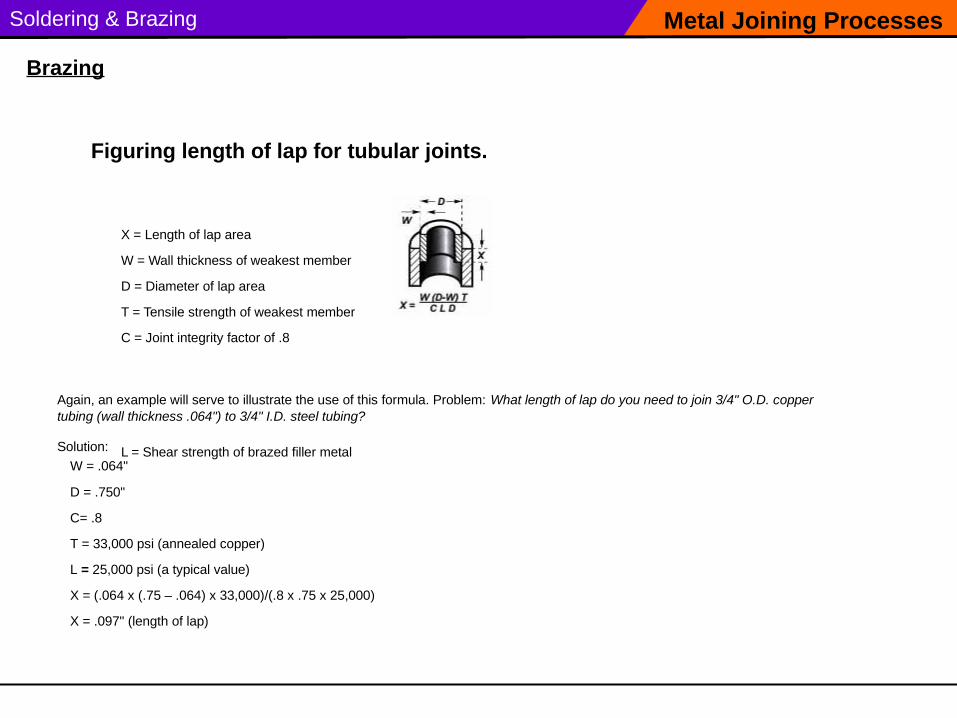
Figuring length of lap for tubular joints.
X = Length of lap area
W = Wall thickness of weakest member
D = Diameter of lap area
T = Tensile strength of weakest member
C = Joint integrity factor of .8
L = Shear strength of brazed filler metal
Again, an example will serve to illustrate the use of this formula. Problem: What length of lap do you need to join 3/4" O.D. copper tubing (wall thickness .064") to 3/4" I.D. steel tubing?
Solution:
W = .064"
D = .750"
C= .8
T = 33,000 psi (annealed copper)
L = 25,000 psi (a typical value)
X = (.064 x (.75 – .064) x 33,000)/(.8 x .75 x 25,000)
X = .097" (length of lap)