Embed Size (px)
Citation preview
Part No. 315396-FJune 2006
4655 Great America ParkwaySanta Clara, CA 95054
Nortel Application Switch Hardware Installation Guide
2
Copyright © Nortel Networks Limited 2005 - 2006. All rights reserved.
The information in this document is subject to change without notice. The statements, configurations, technical data, and recommendations in this document are believed to be accurate and reliable, but are presented without express or implied warranty. Users must take full responsibility for their applications of any products specified in this document. The information in this document is proprietary to Nortel Networks NA Inc.
The software described in this document is furnished under a license agreement and may be used only in accordance with the terms of that license. The software license agreement is included in this document.
Trademarks
*Nortel, Nortel Networks, the Nortel logo, the Globemark, and BayStack are trademarks of Nortel Networks.
Microsoft, MS, MS-DOS, Windows, and Windows NT are registered trademarks of Microsoft Corporation.
Java is a trademark of Sun Microsystems, Inc.
Acrobat and Adobe are trademarks of Adobe Systems, Inc.
All other trademarks and registered trademarks are the property of their respective owners.
The asterisk after a name denotes a trademarked item.
Restricted rights legend
Use, duplication, or disclosure by the United States Government is subject to restrictions as set forth in subparagraph (c)(1)(ii) of the Rights in Technical Data and Computer Software clause at DFARS 252.227-7013.
Notwithstanding any other license agreement that may pertain to, or accompany the delivery of, this computer software, the rights of the United States Government regarding its use, reproduction, and disclosure are as set forth in the Commercial Computer Software-Restricted Rights clause at FAR 52.227-19.
Statement of conditions
In the interest of improving internal design, operational function, and/or reliability, Nortel Networks Inc. reserves the right to make changes to the products described in this document without notice.
Nortel Networks Inc. does not assume any liability that may occur due to the use or application of the product(s) or circuit layout(s) described herein.
Portions of the code in this software product may be Copyright © 1988, Regents of the University of California. All rights reserved. Redistribution and use in source and binary forms of such portions are permitted, provided that the above copyright notice and this paragraph are duplicated in all such forms and that any documentation, advertising materials, and other materials related to such distribution and use acknowledge that such portions of the software were developed by the University of California, Berkeley. The name of the University may not be used to endorse or promote products derived from such portions of the software without specific prior written permission.
SUCH PORTIONS OF THE SOFTWARE ARE PROVIDED “AS IS” AND WITHOUT ANY EXPRESS OR IMPLIED WARRANTIES, INCLUDING, WITHOUT LIMITATION, THE IMPLIED WARRANTIES OF MERCHANTABILITY AND FITNESS FOR A PARTICULAR PURPOSE.
In addition, the program and information contained herein are licensed only pursuant to a license agreement that contains restrictions on use and disclosure (that may incorporate by reference certain limitations and notices imposed by third parties).
315396-F
3
International regulatory statements of conformity
This is to certify that the Nortel Application Switch chassis were evaluated to the international regulatory standards for electromagnetic compliance (EMC) and safety and were found to have met the requirements for the following international standards:
• EMC - Electromagnetic Emissions – CISPR 22, Class A• EMC - Electromagnetic Immunity – CISPR 24• Electrical Safety – IEC 60950, with CB member national deviations
Further, the equipment has been certified as compliant with the national standards as detailed below.
National electromagnetic compliance (EMC) statements of compliance
FCC statement (USA only)
This equipment has been tested and found to comply with the limits for a Class A digital device, pursuant to Part 15 of the Federal Communications Commission (FCC) rules. These limits are designed to provide reasonable protection against harmful interference when the equipment is operated in a commercial environment. This equipment generates, uses, and can radiate radio frequency energy. If it is not installed and used in accordance with the instruction manual, it may cause harmful interference to radio communications. Operation of this equipment in a residential area is likely to cause harmful interference, in which case users will be required to take whatever measures may be necessary to correct the interference at their own expense.
ICES statement (Canada only)
Canadian Department of Communications Radio Interference Regulations
This digital apparatus (Nortel Application Switch chassis) do not exceed the Class A limits for radio-noise emissions from digital apparatus as set out in the Radio Interference Regulations of the Canadian Department of Communications.
Règlement sur le brouillage radioélectrique du ministère des Communications
Cet appareil numérique (Nortel Application Switch chassis) respecte les limites de bruits radioélectriques visant les appareils numériques de classe A prescrites dans le Règlement sur le brouillage radioélectrique du ministère des Communications du Canada.
CE marking statement (Europe only)
EN 55 022 statements
This is to certify that the Nortel Application Switch chassis are shielded against the generation of radio interference in accordance with the application of Council Directive 89/336/EEC. Conformity is declared by the application of EN 55 022 Class A (CISPR 22).
Caution: This device is a Class A product. In a domestic environment, this device can cause radio interference, in which case the user may be required to take appropriate measures.(For translations of this statement, see page 42.)
Nortel Application Switch Hardware Installation Guide

4
EN 55 024 statement
This is to certify that the Nortel Application Switch chassis are shielded against the susceptibility to radio interference in accordance with the application of Council Directive 89/336/EEC. Conformity is declared by the application of EN 55 024 (CISPR 24).
CE Declaration of Conformity
This product conforms to the provisions of the R&TTE Directive 1999/5/EC.
VCCI statement (Japan/Nippon only)
This is a Class A product based on the standard of the Voluntary Control Council for Interference (VCCI) for information technology equipment. If this equipment is used in a domestic environment, radio disturbance may arise. When such trouble occurs, the user may be required to take corrective actions.
Japanese VCCI Class A Statement
MIC notice for Nortel Application Switch chassis (Republic of Korea only)
This device has been approved for use in Business applications only per the Class A requirements of the Republic of Korea Ministry of Information and Communications (MIC). This device may not be sold for use in a non-business application.
Observe the Regulatory Marking label on the bottom surface of the chassis for specific certification information pertaining to this model. Each model in the Application Switch Series which is approved for shipment to/usage in Korea is labeled as such, with all appropriate text and the appropriate MIC reference number.
National safety statements of compliance
CE marking statement (Europe only)
EN 60 950 statement
This is to certify that the Nortel Application Switch chassis are in compliance with the requirements of EN 60 950 in accordance with the Low Voltage Directive. Additional national differences for all European Union countries have been evaluated for compliance
315396-F
5
Japanese Denan safety compliance
Warning: Please be careful of the following while installing the equipment: Please only use the Connecting cables, power cord, AC adaptors shipped with the equipment or specified by Nortel to be used with the equipment. If you use any other equipment, it may cause "failures, malfunctioning or fire". According to the Denan regulation, power cords shipped with this equipment must not be used with any other equipment. In case the above guidelines are not followed, it may lead to death or severe injury.
Nortel Application Switch Hardware Installation Guide

6
315396-F
7
Preface
This manual describes the features, installation process, initial configuration, troubleshooting and specifications of the Application Switch 2208, 2216, 2424, 2424-SSL and 3408.
For full documentation on configuring and using the Application Switch software features, refer to the software manuals listed in “Related Documentation” on page 8.
Who Should Use This Book
This manual is intended for network installers and system administrators engaged in configuring and maintaining a Gigabit Ethernet network. It assumes that you are familiar with Ethernet concepts and the physical process of switch installation.
How This Book Is Organized
This book is broken into sections that describe specific tasks encountered during switch installation and initial configuration. Table 1 outlines the sections of this book.
Table 1 Book Sections
Section Description
The Application Switch This section provides a brief overview of the Application Switch. Information in this section includes a physical description of the front and rear panels, ports, and light emitting diodes (LED) found on the switch. This section begins on page 10.
Installing the Switch Hardware This section lists the items included with the switch and procedures for switch installation and network cable connection. This section begins on page 20.
Initial Configuration This section describes how to configure the switch using a console connection, the Management Port, or a data port. Basic switch operation is also described. This section begins on page 29.
Troubleshooting This section describes how to troubleshoot problems that may occur during the switch installation and configuration process. This section begins on page 35.
Nortel Application Switch Hardware Installation Guide
8
Related Documentation
For detailed information about the functionality and configuration of the Application Switch family, refer to the documents contained on the CD found in the documentation kit supplied with unit. Documentation can also be accessed by referring to the following URL:
http://www.nortel.com
How to Get Help
If a service contract has been purchased for the Nortel Networks product from a distributor or authorized reseller, contact the technical support staff for that distributor or reseller for assistance.
If a Nortel Networks service program has been purchased for the product, contact one of the following Nortel Networks Technical Solutions Centers:
• Europe, Middle East, and Africa
00800 8008 9009 or +44 (0) 870 907 9009
• North America
(800) 4NORTEL or (800) 466-7835
• Asia Pacific
(61) (2) 8870-8800
• China
(800) 810-5000
Switch Specifications This section describes the supported standards and physical, environmental, and mechanical specifications of the switch. This section also lists switch certifications. This section begins on page 37.
Translations of Safety Messages This section provides translations for the English safety and cautionary statements that appear in this book. This section begins on page 42.
Table 1 Book Sections (continued)
Section Description
315396-F
9
Additional information about the Nortel Networks Technical Solutions Centers is available at:
http://www.nortel.com/help/contact/global
An Express Routing Code (ERC) is available for many Nortel Networks products and services. When you use an ERC, your call is routed to a technical support person who specializes in supporting that product or service. To locate an ERC for your product or service, refer to the following URL:
http://www.nortel.com/help/contact/erc/index.html
Nortel Application Switch Hardware Installation Guide
10
The Application Switch
Overview
The Application Switch 2000 (2208, 2216, 2424, and 2424-SSL) and 3000 (3408) series are multi-application switching systems that perform wire-speed Layer 2/3 switching and high-performance Layer 4-7 intelligent traffic management. In addition, the 2424-SSL has an integrated Secure Sockets Layer (SSL) Accelerator blade that off-loads multi-layer security functions to protect networks and applications without impacting overall switch performance.
The Application Switch attaches to network backbones and interconnects servers using 10/100 and 1000BaseT Mbps (supported only on 3000 series) Base-T and Gigabit Ethernet connections. This flexibility off-loads server-to-server traffic from the backbone, frees backbone bandwidth, and accelerates client-server performance.
Physical Description
The Application Switch series has two variants that are identified with an E or a DC at the end of the model name. The E variant is an enhanced version which is built to conform with the European Union Environmental Directive (EUED) for Restriction of Hazardous Substances (RoHS) . The DC variant includes all of the E variant enhancements, but is designed to operate on -48 Volts DC. The illustrations in this section provide a visual representation of the various switches in the Application Switch 2000 E and 3000 E series. Where appropriate, additional information is provided to explain these physical representations. No attempt is made to include all three views of the base model and the two variants for each figure.
Front Panel
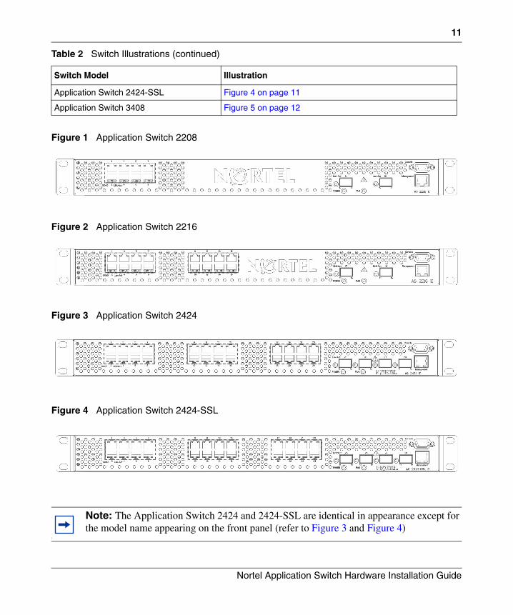
The following illustrations provide a visual representation of the Application Switch 2000 and 3000 series front panels. Refer to the following table to locate the illustration for a specific switch.
Table 2 Switch Illustrations
Switch Model Illustration
Application Switch 2208 Figure 1 on page 11
Application Switch 2216 Figure 2 on page 11
Application Switch 2424 Figure 3 on page 11
315396-F
11
Figure 1 Application Switch 2208
Figure 2 Application Switch 2216
Figure 3 Application Switch 2424
Figure 4 Application Switch 2424-SSL
Application Switch 2424-SSL Figure 4 on page 11
Application Switch 3408 Figure 5 on page 12
1
Note: The Application Switch 2424 and 2424-SSL are identical in appearance except for the model name appearing on the front panel (refer to Figure 3 and Figure 4)
Table 2 Switch Illustrations (continued)
Switch Model Illustration
Nortel Application Switch Hardware Installation Guide
12
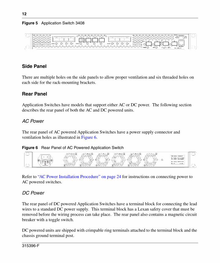
Figure 5 Application Switch 3408
Side Panel
There are multiple holes on the side panels to allow proper ventilation and six threaded holes on each side for the rack-mounting brackets.
Rear Panel
Application Switches have models that support either AC or DC power. The following section describes the rear panel of both the AC and DC powered units.
AC Power
The rear panel of AC powered Application Switches have a power supply connector and ventilation holes as illustrated in Figure 6.
Figure 6 Rear Panel of AC Powered Application Switch
Refer to “AC Power Installation Procedure” on page 24 for instructions on connecting power to AC powered switches.
DC Power
The rear panel of DC powered Application Switches have a terminal block for connecting the lead wires to a standard DC power supply. This terminal block has a Lexan safety cover that must be removed before the wiring process can take place. The rear panel also contains a magnetic circuit breaker with a toggle switch.
DC powered units are shipped with crimpable ring terminals attached to the terminal block and the chassis ground terminal post.
315396-F
13
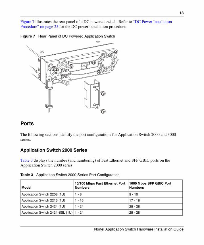
Figure 7 illustrates the rear panel of a DC powered switch. Refer to “DC Power Installation Procedure” on page 25 for the DC power installation procedure.
Figure 7 Rear Panel of DC Powered Application Switch
Ports
The following sections identify the port configurations for Application Switch 2000 and 3000 series.
Application Switch 2000 Series
Table 3 displays the number (and numbering) of Fast Ethernet and SFP GBIC ports on the Application Switch 2000 series.
Table 3 Application Switch 2000 Series Port Configuration
Model10/100 Mbps Fast Ethernet Port Numbers
1000 Mbps SFP GBIC Port Numbers
Application Switch 2208 (1U) 1 - 8 9 - 10
Application Switch 2216 (1U) 1 - 16 17 - 18
Application Switch 2424 (1U) 1 - 24 25 - 28
Application Switch 2424-SSL (1U) 1 - 24 25 - 28
Nortel Application Switch Hardware Installation Guide
14
Fast Ethernet Ports
The RJ-45 jack is used for connecting 10/100 Mbps Ethernet segments to the port. The ports are auto-sensing, auto-negotiating, and support half or full-duplex operation.
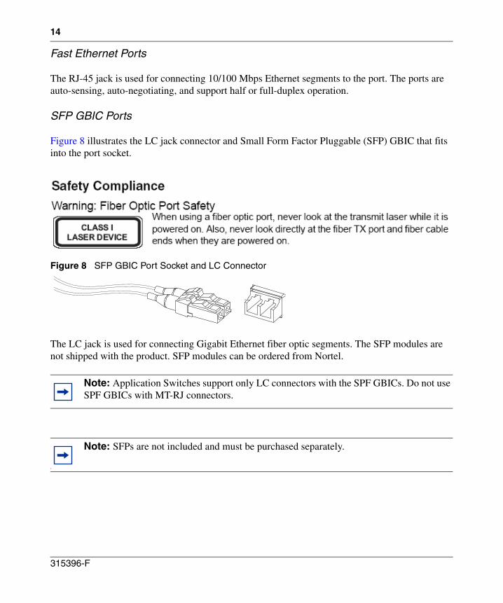
SFP GBIC Ports
Figure 8 illustrates the LC jack connector and Small Form Factor Pluggable (SFP) GBIC that fits into the port socket.
Figure 8 SFP GBIC Port Socket and LC Connector
The LC jack is used for connecting Gigabit Ethernet fiber optic segments. The SFP modules are not shipped with the product. SFP modules can be ordered from Nortel.
Note: Application Switches support only LC connectors with the SPF GBICs. Do not use SPF GBICs with MT-RJ connectors.
1
Note: SFPs are not included and must be purchased separately.
315396-F
15
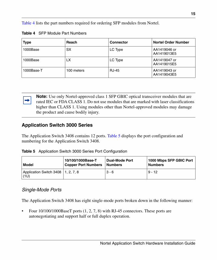
Table 4 lists the part numbers required for ordering SFP modules from Nortel.
Application Switch 3000 Series
The Application Switch 3408 contains 12 ports. Table 5 displays the port configuration and numbering for the Application Switch 3408.
Single-Mode Ports
The Application Switch 3408 has eight single-mode ports broken down in the following manner:
• Four 10/100/1000BaseT ports (1, 2, 7, 8) with RJ-45 connectors. These ports are autonegotiating and support half or full duplex operation.
Table 4 SFP Module Part Numbers
Type Reach Connector Nortel Order Number
1000Base SX LC Type AA1419046 or AA1419013E5
1000Base LX LC Type AA1419047 or AA1419015E5
1000Base-T 100 meters RJ-45 AA1419043 or AA1419043E5
Note: Use only Nortel-approved class 1 SFP GBIC optical transceiver modules that are rated IEC or FDA CLASS 1. Do not use modules that are marked with laser classifications higher than CLASS 1. Using modules other than Nortel-approved modules may damage the product and cause bodily injury.
Table 5 Application Switch 3000 Series Port Configuration
Model10/100/1000Base-T Copper Port Numbers
Dual-Mode Port Numbers
1000 Mbps SFP GBIC Port Numbers
Application Switch 3408 (1U)
1, 2, 7, 8 3 - 6 9 - 12
Nortel Application Switch Hardware Installation Guide
16
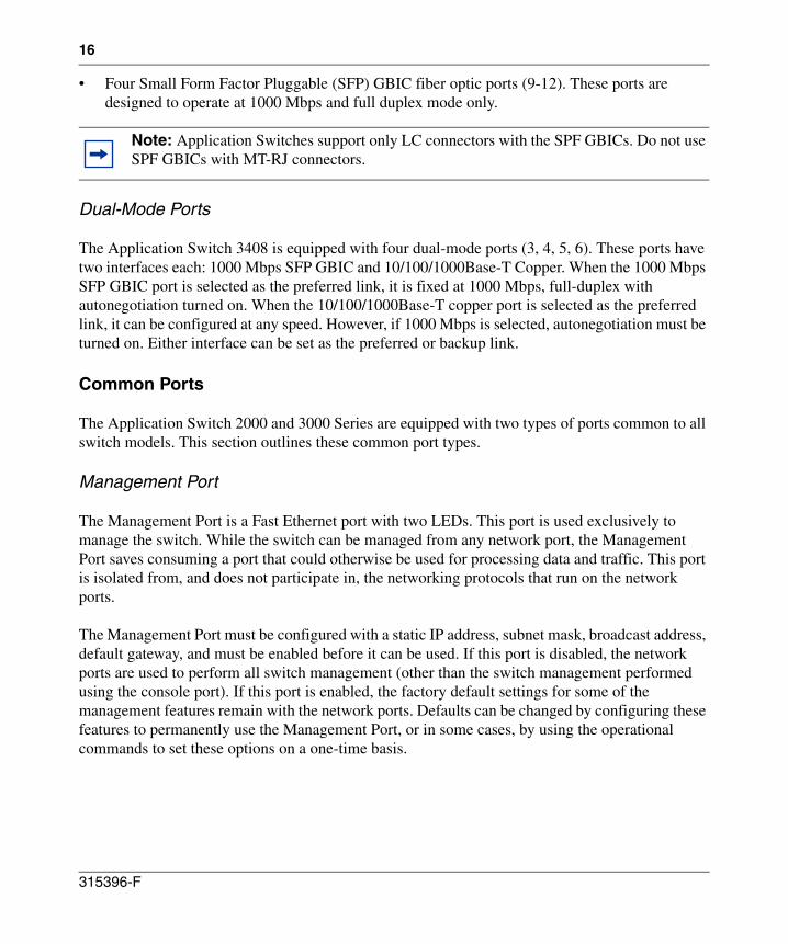
• Four Small Form Factor Pluggable (SFP) GBIC fiber optic ports (9-12). These ports are designed to operate at 1000 Mbps and full duplex mode only.
Dual-Mode Ports
The Application Switch 3408 is equipped with four dual-mode ports (3, 4, 5, 6). These ports have two interfaces each: 1000 Mbps SFP GBIC and 10/100/1000Base-T Copper. When the 1000 Mbps SFP GBIC port is selected as the preferred link, it is fixed at 1000 Mbps, full-duplex with autonegotiation turned on. When the 10/100/1000Base-T copper port is selected as the preferred link, it can be configured at any speed. However, if 1000 Mbps is selected, autonegotiation must be turned on. Either interface can be set as the preferred or backup link.
Common Ports
The Application Switch 2000 and 3000 Series are equipped with two types of ports common to all switch models. This section outlines these common port types.
Management Port
The Management Port is a Fast Ethernet port with two LEDs. This port is used exclusively to manage the switch. While the switch can be managed from any network port, the Management Port saves consuming a port that could otherwise be used for processing data and traffic. This port is isolated from, and does not participate in, the networking protocols that run on the network ports.
The Management Port must be configured with a static IP address, subnet mask, broadcast address, default gateway, and must be enabled before it can be used. If this port is disabled, the network ports are used to perform all switch management (other than the switch management performed using the console port). If this port is enabled, the factory default settings for some of the management features remain with the network ports. Defaults can be changed by configuring these features to permanently use the Management Port, or in some cases, by using the operational commands to set these options on a one-time basis.
Note: Application Switches support only LC connectors with the SPF GBICs. Do not use SPF GBICs with MT-RJ connectors.
315396-F
17
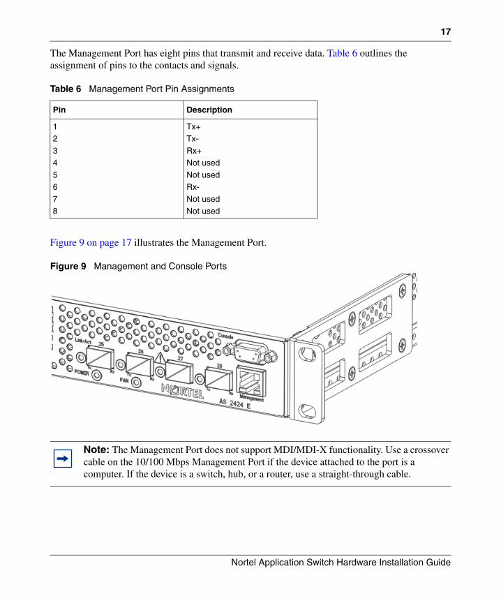
The Management Port has eight pins that transmit and receive data. Table 6 outlines the assignment of pins to the contacts and signals.
Figure 9 on page 17 illustrates the Management Port.
Figure 9 Management and Console Ports
Table 6 Management Port Pin Assignments
Pin Description
1
2
34
5
67
8
Tx+
Tx-
Rx+Not used
Not used
Rx-Not used
Not used
1
Note: The Management Port does not support MDI/MDI-X functionality. Use a crossover cable on the 10/100 Mbps Management Port if the device attached to the port is a computer. If the device is a switch, hub, or a router, use a straight-through cable.
Nortel Application Switch Hardware Installation Guide
18
Console Port
The console port consists of a female DB-9 serial connector labeled Console for the DCE connector. Figure 9 illustrates the Console Port. See “Connecting Cables to Console Port” on page 28 for details on establishing a Console Port connection.
LEDs
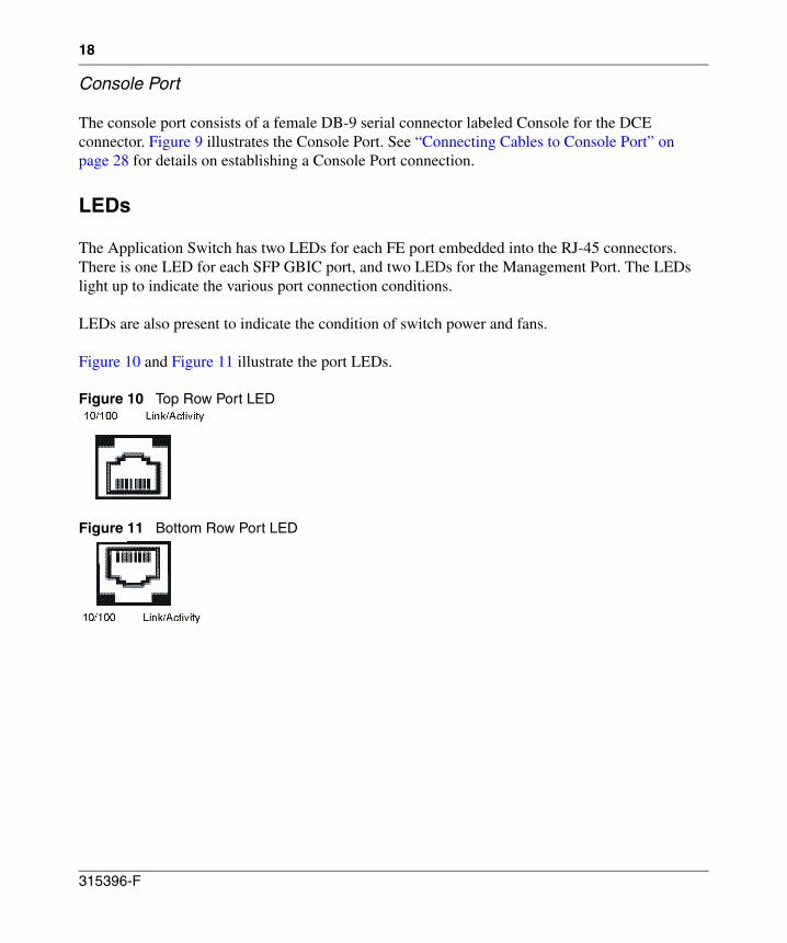
The Application Switch has two LEDs for each FE port embedded into the RJ-45 connectors. There is one LED for each SFP GBIC port, and two LEDs for the Management Port. The LEDs light up to indicate the various port connection conditions.
LEDs are also present to indicate the condition of switch power and fans.
Figure 10 and Figure 11 illustrate the port LEDs.
Figure 10 Top Row Port LED
Figure 11 Bottom Row Port LED
315396-F
19
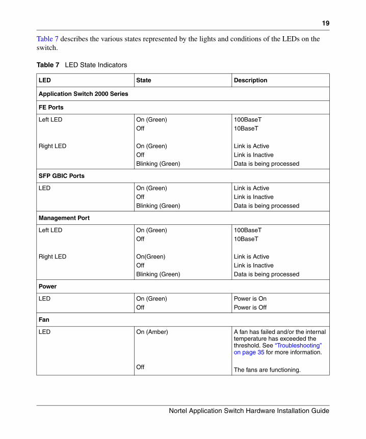
Table 7 describes the various states represented by the lights and conditions of the LEDs on the switch.
Table 7 LED State Indicators
LED State Description
Application Switch 2000 Series
FE Ports
Left LED
Right LED
On (Green)
Off
On (Green)
OffBlinking (Green)
100BaseT
10BaseT
Link is Active
Link is InactiveData is being processed
SFP GBIC Ports
LED On (Green)
Off
Blinking (Green)
Link is Active
Link is Inactive
Data is being processed
Management Port
Left LED
Right LED
On (Green)Off
On(Green)Off
Blinking (Green)
100BaseT10BaseT
Link is ActiveLink is Inactive
Data is being processed
Power
LED On (Green)
Off
Power is On
Power is Off
Fan
LED On (Amber)
Off
A fan has failed and/or the internal temperature has exceeded the threshold. See “Troubleshooting” on page 35 for more information.
The fans are functioning.
Nortel Application Switch Hardware Installation Guide
20
Installing the Switch Hardware
This section describes how to install the Application Switch and connect cables to the network ports, the management port, and the console port.
Package Contents
An Application Switch is shipped with the following items:
• Two mounting brackets for a 19” rack or wall mounting.
• Eight Phillips screws for installing the mounting brackets of the Nortel Application Switch unit and twelve Phillips screws for installing the mounting brackets of the E and DC variants.
• Unless otherwise specified by the customer, the AC powered Application Switch is shipped with two AC power cords, one for North America and one for Europe. Table 8 contains a listing of order numbers for regional power cords.
• Console cable.
• A documentation kit containing this Installation Guide, software manuals and a software CD
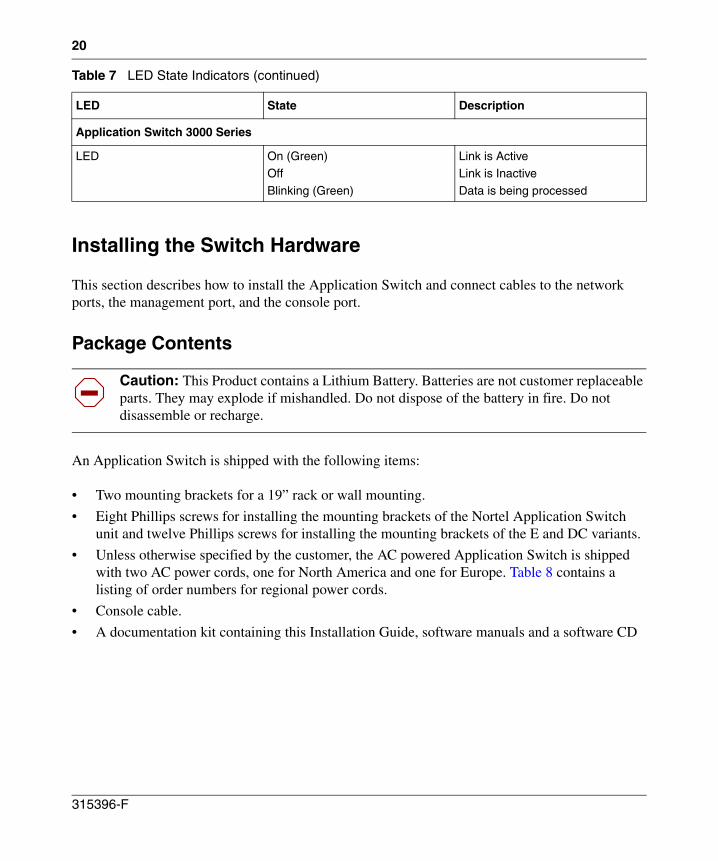
Application Switch 3000 Series
LED On (Green)Off
Blinking (Green)
Link is ActiveLink is Inactive
Data is being processed
Caution: This Product contains a Lithium Battery. Batteries are not customer replaceable parts. They may explode if mishandled. Do not dispose of the battery in fire. Do not disassemble or recharge.
Table 7 LED State Indicators (continued)
LED State Description
315396-F
21
.
Installation Preparation
Switch installation involves the following tasks:
1 Choosing a suitable location to install the switch.
2 Unpacking the switch from the box.
3 Turning the power switch to the Off (O) position.
4 Mounting the switch.
5 Connecting the power inlet of the switch to the appropriate power source. Refer to “AC Power Installation Procedure” on page 24 and “DC Power Installation Procedure” on page 25 for detailed information on completing this task.
6 Connecting network cables to the switch.
7 Powering on the switch.
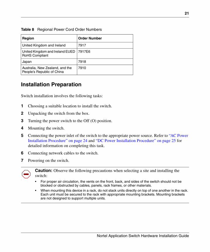
Table 8 Regional Power Cord Order Numbers
Region Order Number
United Kingdom and Ireland 7917
United Kingdom and Ireland EUED RoHS Compliant
7917E6
Japan 7918
Australia, New Zealand, and the People’s Republic of China
7910
1
Caution: Observe the following precautions when selecting a site and installing the switch:• For proper air circulation, the vents on the front, back, and sides of the switch should not be
blocked or obstructed by cables, panels, rack frames, or other materials.
• When mounting this device in a rack, do not stack units directly on top of one another in the rack. Each unit must be secured to the rack with appropriate mounting brackets. Mounting brackets are not designed to support multiple units.
Nortel Application Switch Hardware Installation Guide
22
Installing the Switch
The following section outlines the procedures necessary for physically installing the switch.
Rack-Mounting the Switch
Application Switches have models that support either AC or DC power. The following procedure describes the rack-mounting process for both types of units:
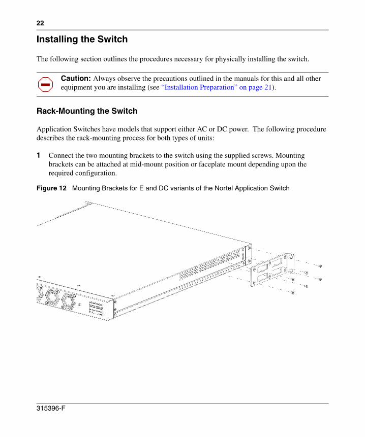
1 Connect the two mounting brackets to the switch using the supplied screws. Mounting brackets can be attached at mid-mount position or faceplate mount depending upon the required configuration.
Figure 12 Mounting Brackets for E and DC variants of the Nortel Application Switch
1
Caution: Always observe the precautions outlined in the manuals for this and all other equipment you are installing (see “Installation Preparation” on page 21).
315396-F
23
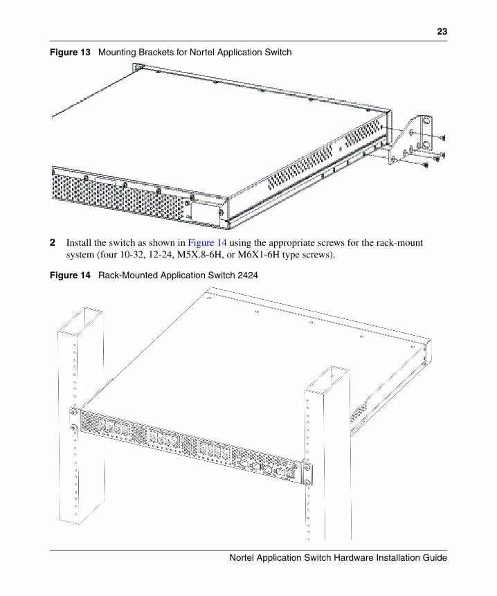
Figure 13 Mounting Brackets for Nortel Application Switch
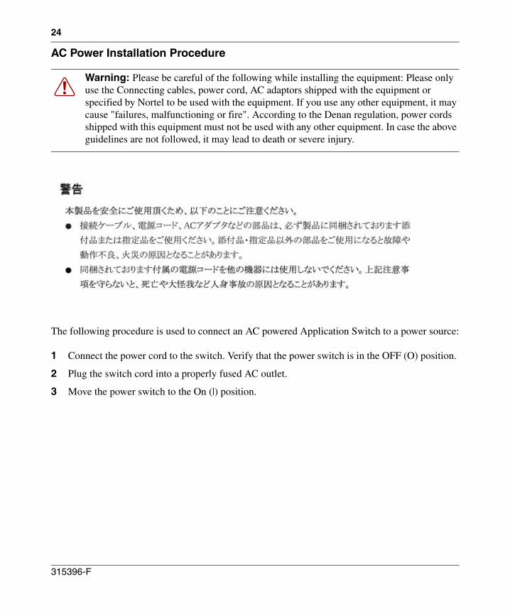
2 Install the switch as shown in Figure 14 using the appropriate screws for the rack-mount system (four 10-32, 12-24, M5X.8-6H, or M6X1-6H type screws).
Figure 14 Rack-Mounted Application Switch 2424
Nortel Application Switch Hardware Installation Guide
24
AC Power Installation Procedure
The following procedure is used to connect an AC powered Application Switch to a power source:
1 Connect the power cord to the switch. Verify that the power switch is in the OFF (O) position.
2 Plug the switch cord into a properly fused AC outlet.
3 Move the power switch to the On (|) position.
Warning: Please be careful of the following while installing the equipment: Please only use the Connecting cables, power cord, AC adaptors shipped with the equipment or specified by Nortel to be used with the equipment. If you use any other equipment, it may cause "failures, malfunctioning or fire". According to the Denan regulation, power cords shipped with this equipment must not be used with any other equipment. In case the above guidelines are not followed, it may lead to death or severe injury.
315396-F
25
DC Power Installation Procedure
Use the following procedure to connect a DC powered switch to a -48 to -75 VDC source only, in compliance with National Electrical Code (NEC) articles 110-26 and 110-27.
Collect, and have within easy reach, the following items before starting this procedure:
• Phillips screwdriver
• Wire crimper
• 14 to 16 American Wire Gage (AWG) copper conductor wire
1 Ensure that the DC power is turned off at the source.
2 Ensure that the magnetic circuit breaker illustrated in Figure 7 on page 13 is in the OFF (O) position.
3 Connect the DC earth-ground lead to the switch earth-ground terminal.
Take the following steps to connect the DC earth-ground lead to the switch earth-ground terminal:
• Loosen the 6-32 nut from the stud of the switch earth-ground terminal and remove the ring terminal that is provided with the unit.
• Strip half a centimeter of insulation from one end of the intended ground wire. As noted, this wire should be between 14 and 16 American Wire Gage copper conductor wire.
• Crimp this wire into the ring terminal provided.
• Install the crimped ring terminal over the chassis earth-ground terminal post.
• Tighten the 6-32 nut to secure the ring terminal into place.
1
Note: Ensure that this procedure has been fully read and understood before attempting to install the DC power.
1
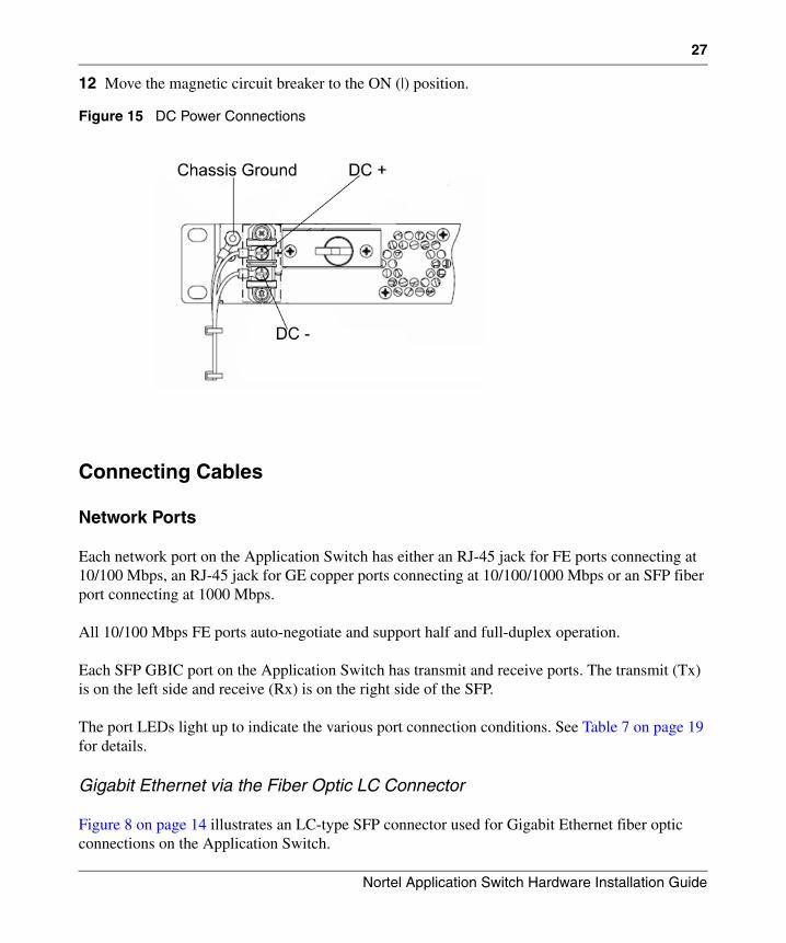
Note: The location and appearance of the switch earth-ground terminal is illustrated in Figure 15 on page 27.
1
Note: The switch must be connected to a protective earthing terminal in accordance with the National Electrical Code (NEC) article 250-160.
Nortel Application Switch Hardware Installation Guide
26
4 Connect the DC earth-ground lead prepared in Step 3 to the earth-ground terminal on the DC power source.
5 Remove the Lexan protective cover from the terminal block by loosening and removing the 6-32 screws and washers. The location and appearance of the Lexan protective cover is illustrated in Figure 7 on page 13.
6 Remove the two ring terminals that are attached to the exposed terminal block by removing the 6-32 screw on each terminal.
7 Crimp each DC power lead to each of the ring terminals removed in Step 6.
Take the following steps to crimp each DC power lead to each ring terminal:
• Strip half a centimeter of insulation from one end of each of the intended DC power leads. As noted, this wire should be between 14 and 16 American Wire Gage copper conductor wire.
• Crimp one end of each DC power lead into the ring terminals provided.
8 Connect each of the DC power leads to the appropriate, polarized terminal on the switch.
Take the following steps to connect the DC power leads:
• Install the two crimped ring terminals prepared in Step 7 into the terminal block.
• Tighten the 6-32 screws to secure each ring terminal in place.
9 Connect the other end of each DC power lead to the appropriate wire terminal of the DC power source.
Take the following steps to connect the DC power leads:
• Connect the DC “+” (common) switch terminal to the source DC “+” common power terminal.
• Connect the DC “-” (-48) switch terminal to the -48 VDC source relative to common.
10 Re-install the terminal block Lexan protective safety cover using the hardware that was removed in Step 5.
11 Turn on DC power at the source.
1
Note: The location and appearance of these terminals is illustrated in Figure 15 on page 27.
1
Caution: Be certain that the DC power leads are correctly connected. Improper power connection may cause damage to the unit.
315396-F
27
12 Move the magnetic circuit breaker to the ON (|) position.
Figure 15 DC Power Connections
Connecting Cables
Network Ports
Each network port on the Application Switch has either an RJ-45 jack for FE ports connecting at 10/100 Mbps, an RJ-45 jack for GE copper ports connecting at 10/100/1000 Mbps or an SFP fiber port connecting at 1000 Mbps.
All 10/100 Mbps FE ports auto-negotiate and support half and full-duplex operation.
Each SFP GBIC port on the Application Switch has transmit and receive ports. The transmit (Tx) is on the left side and receive (Rx) is on the right side of the SFP.
The port LEDs light up to indicate the various port connection conditions. See Table 7 on page 19 for details.
Gigabit Ethernet via the Fiber Optic LC Connector
Figure 8 on page 14 illustrates an LC-type SFP connector used for Gigabit Ethernet fiber optic connections on the Application Switch.
Nortel Application Switch Hardware Installation Guide
28
10/100 Mbps Ethernet via the RJ-45 Connector
If an Application Switch is configured for auto-negotiate mode, the FE port will automatically determine the Rx & Tx pins of the link (the MDI/MDI-X functionality). If the auto-negotiate mode is disabled, a crossover cable must be used when connecting the Application Switch FE port to another switch. Use a straight through cable when connecting to an end station, such as a PC.
Management Port
The Management Port on an Application Switch has one RJ-45 jack for connecting 10/100 Mbps Fast Ethernet segments to the port.
The port LEDs light up to indicate the various port connection conditions. See Table 7 on page 19 for details.
Connecting Cables to Console Port
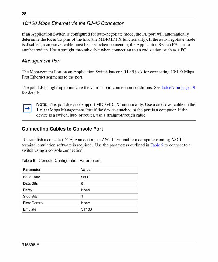
To establish a console (DCE) connection, an ASCII terminal or a computer running ASCII terminal emulation software is required. Use the parameters outlined in Table 9 to connect to a switch using a console connection.
1
Note: This port does not support MDI/MDI-X functionality. Use a crossover cable on the 10/100 Mbps Management Port if the device attached to the port is a computer. If the device is a switch, hub, or router, use a straight-through cable.
Table 9 Console Configuration Parameters
Parameter Value
Baud Rate 9600
Data Bits 8
Parity None
Stop Bits 1
Flow Control None
Emulate VT100
315396-F
29
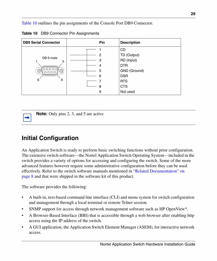
Table 10 outlines the pin assignments of the Console Port DB9 Connector.
Initial Configuration
An Application Switch is ready to perform basic switching functions without prior configuration. The extensive switch software—the Nortel Application Switch Operating System—included in the switch provides a variety of options for accessing and configuring the switch. Some of the more advanced features however require some administrative configuration before they can be used effectively. Refer to the switch software manuals mentioned in “Related Documentation” on page 8 and that were shipped in the software kit of this product.
The software provides the following:
• A built-in, text-based command line interface (CLI) and menu system for switch configuration and management through a local terminal or remote Telnet session.
• SNMP support for access through network management software such as HP OpenView*.
• A Browser-Based Interface (BBI) that is accessible through a web browser after enabling http access using the IP address of the switch.
• A GUI application, the Application Switch Element Manager (ASEM), for interactive network access.
Table 10 DB9 Connector Pin Assignments
DB9 Serial Connector Pin Description
12
3
45
6
78
9
CDTD (Output)
RD (Input)
DTRGND (Ground)
DSR
RTSCTS
Not used
1
Note: Only pins 2, 3, and 5 are active
1 5
6 9
DB-9 male
Nortel Application Switch Hardware Installation Guide
30
Initial Configuration of the Switch
The Application Switch has a Console Port, Management Port and network ports that can be used for installing software and configuring the switch. This section explains how to perform the initial configuration of the switch using these ports.
For detailed instructions on using the console to view and configure switch settings, refer to the appropriate switch software manuals.
Configuring the Switch
Initial switch configuration and management can be accomplished in a number of ways. An Application Switch allows these tasks to be performed by way of a console connection, Telnet session, or SSH connection.
The following sections detail the procedures necessary to establish one of these connections for initial switch configuration.
Establishing a Console Connection
Use the following procedure to establish a console connection with the switch:
1 Connect the terminal, or computer running terminal emulation software, to the Console Port of the switch using the serial cable.
2 If using an ASCII terminal, power on the terminal. If using a computer with terminal emulation software, run the terminal emulation program and enter the parameters outlined in Table 9 on page 28.
3 If using an ASCII terminal, press Enter a few times on the terminal to establish the connection. If using a computer with terminal emulation software, perform the functions necessary to connect to the switch,
If the connection has been successfully established, a login prompt will be displayed and a password will be requested. The default administrator password is admin. The CLI main menu will be displayed once the password entered has been verified.
For information on using the CLI menus for switch configuration, refer to the appropriate switch software manuals.
315396-F
31
Establishing a Telnet Connection
A Telnet connection offers the convenience of accessing the switch from any computer connected to the network. Telnet access provides the same options for user and administrator access as those available through the console port.
To connect to a switch through Telnet, use a computer running Telnet software located on the same network as the switch. Before a Telnet session can be established, the switch must have an IP address. The switch can assigned an IP address either dynamically from a network BOOTP server or manually during the switch configuration process.
Establishing an SSH Connection
Although a remote network administrator can manage the configuration of an Application Switch through Telnet, this method does not provide a secure connection. The SSH (Secure Shell) protocol enables secure remote login and communication not provided by Telnet. As a secure alternative to using Telnet to manage switch configuration, SSH ensures that all data sent over the network is encrypted and secure.
For detailed information on how to establish an SSH connection, refer to the Command Reference contained on the CD supplied as part of the documentation kit provided with the unit.
1
Note: To use the Management Port, the port must be manually configured with a unique IP address.
Nortel Application Switch Hardware Installation Guide
32
Initial Switch Connection
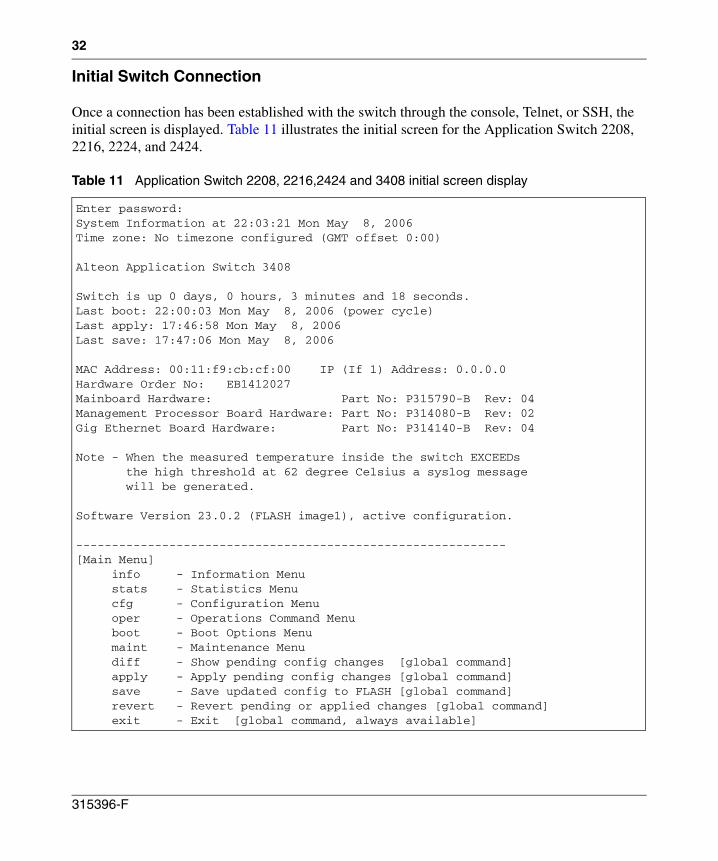
Once a connection has been established with the switch through the console, Telnet, or SSH, the initial screen is displayed. Table 11 illustrates the initial screen for the Application Switch 2208, 2216, 2224, and 2424.
Table 11 Application Switch 2208, 2216,2424 and 3408 initial screen display
Enter password: System Information at 22:03:21 Mon May 8, 2006 Time zone: No timezone configured (GMT offset 0:00)
Alteon Application Switch 3408
Switch is up 0 days, 0 hours, 3 minutes and 18 seconds. Last boot: 22:00:03 Mon May 8, 2006 (power cycle) Last apply: 17:46:58 Mon May 8, 2006 Last save: 17:47:06 Mon May 8, 2006
MAC Address: 00:11:f9:cb:cf:00 IP (If 1) Address: 0.0.0.0 Hardware Order No: EB1412027 Mainboard Hardware: Part No: P315790-B Rev: 04 Management Processor Board Hardware: Part No: P314080-B Rev: 02 Gig Ethernet Board Hardware: Part No: P314140-B Rev: 04
Note - When the measured temperature inside the switch EXCEEDs the high threshold at 62 degree Celsius a syslog message will be generated.
Software Version 23.0.2 (FLASH image1), active configuration.
------------------------------------------------------------ [Main Menu] info - Information Menu stats - Statistics Menu cfg - Configuration Menu oper - Operations Command Menu boot - Boot Options Menu maint - Maintenance Menu diff - Show pending config changes [global command] apply - Apply pending config changes [global command] save - Save updated config to FLASH [global command] revert - Revert pending or applied changes [global command] exit - Exit [global command, always available]
315396-F
33
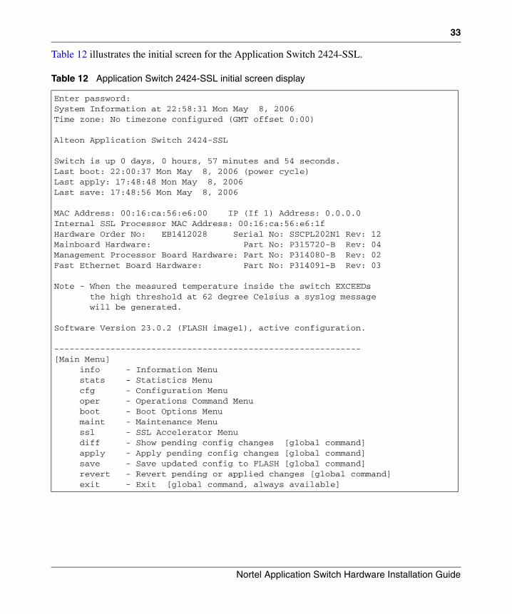
Table 12 illustrates the initial screen for the Application Switch 2424-SSL.
Table 12 Application Switch 2424-SSL initial screen display
Enter password:System Information at 22:58:31 Mon May 8, 2006 Time zone: No timezone configured (GMT offset 0:00)
Alteon Application Switch 2424-SSL
Switch is up 0 days, 0 hours, 57 minutes and 54 seconds. Last boot: 22:00:37 Mon May 8, 2006 (power cycle) Last apply: 17:48:48 Mon May 8, 2006 Last save: 17:48:56 Mon May 8, 2006
MAC Address: 00:16:ca:56:e6:00 IP (If 1) Address: 0.0.0.0 Internal SSL Processor MAC Address: 00:16:ca:56:e6:1f Hardware Order No: EB1412028 Serial No: SSCPL202N1 Rev: 12 Mainboard Hardware: Part No: P315720-B Rev: 04 Management Processor Board Hardware: Part No: P314080-B Rev: 02 Fast Ethernet Board Hardware: Part No: P314091-B Rev: 03
Note - When the measured temperature inside the switch EXCEEDs the high threshold at 62 degree Celsius a syslog message will be generated.
Software Version 23.0.2 (FLASH image1), active configuration.
------------------------------------------------------------ [Main Menu] info - Information Menu stats - Statistics Menu cfg - Configuration Menu oper - Operations Command Menu boot - Boot Options Menu maint - Maintenance Menu ssl - SSL Accelerator Menu diff - Show pending config changes [global command] apply - Apply pending config changes [global command] save - Save updated config to FLASH [global command] revert - Revert pending or applied changes [global command] exit - Exit [global command, always available]
Nortel Application Switch Hardware Installation Guide
34
Using the Management Port
The Management Port allows the switch to be managed without taking any of the data ports offline. Refer to “Management Port” on page 16 for additional information on the Management Port. For more information on the configuration and usage of the Management Port, refer to the Command Reference contained on the CD supplied as part of the documentation kit provided with the unit.
The integrated SSL Accelerator blade on the Application Switch 2424-SSL is configurable through the Management Port but cannot be managed remotely. For remote management a network data port must be used.
Using Network Ports
Establish connections between the switch and the server with the help of the network ports using connectors and cables. Apart from establishing a Layer 2 link, network data ports can also be used to manage the switch.
More information on using the network ports can be found in the Command Reference contained on the CD supplied as part of the documentation kit provided with the unit.
Upgrading the Software
The Application Switch is provided with software installed and configured with factory default settings. For more information about upgrading the switch software, refer to the Command Reference contained on the CD supplied as part of the documentation kit provided with the unit. To upgrade an Application Switch 2424-SSL, refer to the SSL Accelerator Command Reference supplied as part of the documentation kit provided with the unit.
315396-F
35
Troubleshooting
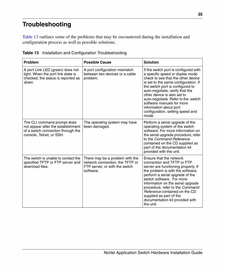
Table 13 outlines some of the problems that may be encountered during the installation and configuration process as well as possible solutions.
Table 13 Installation and Configuration Troubleshooting
Problem Possible Cause Solution
A port Link LED (green) does not light. When the port link state is checked, the status is reported as down.
A port configuration mismatch between two devices or a cable problem.
If the switch port is configured with a specific speed or duplex mode check to see that the other device is set to the same configuration. If the switch port is configured to auto-negotiate, verify that the other device is also set to auto-negotiate. Refer to the switch software manuals for more information about port configuration, setting speed and mode.
The CLI command prompt does not appear after the establishment of a switch connection through the console, Telnet, or SSH.
The operating system may have been damaged.
Perform a serial upgrade of the operating system of the switch software. For more information on the serial upgrade procedure, refer to the Command Reference contained on the CD supplied as part of the documentation kit provided with the unit.
The switch is unable to contact the specified TFTP or FTP server and download files.
There may be a problem with the network connection, the TFTP or FTP server, or with the switch software.
Ensure that the network connection and TFTP or FTP server are functioning properly. If the problem is with the software, perform a serial upgrade of the switch software. For more information on the serial upgrade procedure, refer to the Command Reference contained on the CD supplied as part of the documentation kit provided with the unit.
Nortel Application Switch Hardware Installation Guide
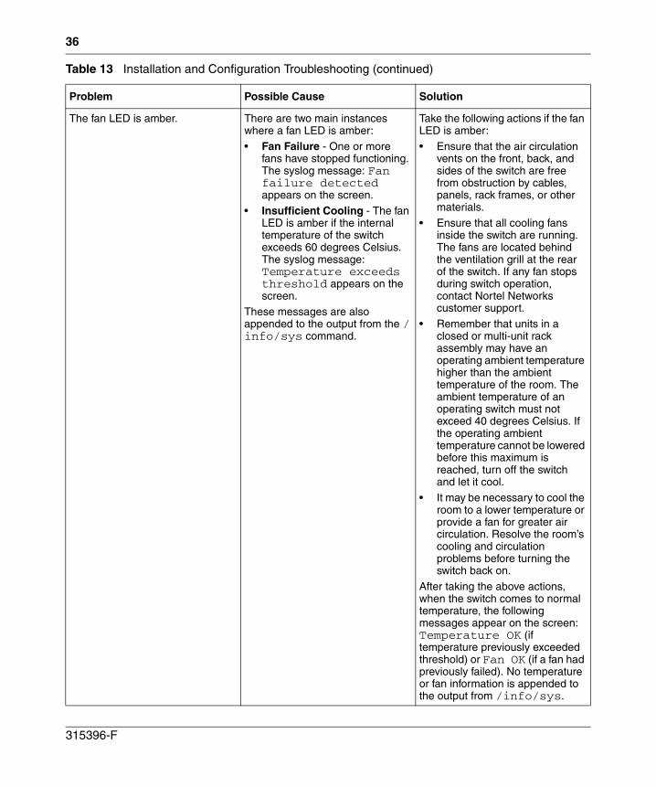
36
The fan LED is amber. There are two main instances where a fan LED is amber:
• Fan Failure - One or more fans have stopped functioning. The syslog message: Fan failure detected appears on the screen.
• Insufficient Cooling - The fan LED is amber if the internal temperature of the switch exceeds 60 degrees Celsius. The syslog message: Temperature exceeds threshold appears on the screen.
These messages are also appended to the output from the /info/sys command.
Take the following actions if the fan LED is amber:
• Ensure that the air circulation vents on the front, back, and sides of the switch are free from obstruction by cables, panels, rack frames, or other materials.
• Ensure that all cooling fans inside the switch are running. The fans are located behind the ventilation grill at the rear of the switch. If any fan stops during switch operation, contact Nortel Networks customer support.
• Remember that units in a closed or multi-unit rack assembly may have an operating ambient temperature higher than the ambient temperature of the room. The ambient temperature of an operating switch must not exceed 40 degrees Celsius. If the operating ambient temperature cannot be lowered before this maximum is reached, turn off the switch and let it cool.
• It may be necessary to cool the room to a lower temperature or provide a fan for greater air circulation. Resolve the room’s cooling and circulation problems before turning the switch back on.
After taking the above actions, when the switch comes to normal temperature, the following messages appear on the screen: Temperature OK (if temperature previously exceeded threshold) or Fan OK (if a fan had previously failed). No temperature or fan information is appended to the output from /info/sys.
Table 13 Installation and Configuration Troubleshooting (continued)
Problem Possible Cause Solution
315396-F
37
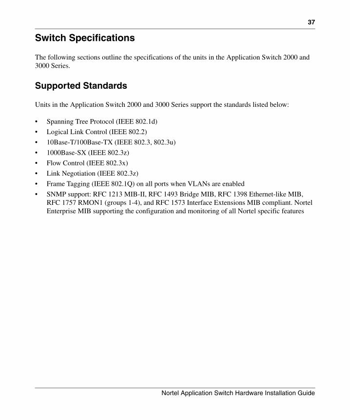
Switch Specifications
The following sections outline the specifications of the units in the Application Switch 2000 and 3000 Series.
Supported Standards
Units in the Application Switch 2000 and 3000 Series support the standards listed below:
• Spanning Tree Protocol (IEEE 802.1d)
• Logical Link Control (IEEE 802.2)
• 10Base-T/100Base-TX (IEEE 802.3, 802.3u)
• 1000Base-SX (IEEE 802.3z)
• Flow Control (IEEE 802.3x)
• Link Negotiation (IEEE 802.3z)
• Frame Tagging (IEEE 802.1Q) on all ports when VLANs are enabled
• SNMP support: RFC 1213 MIB-II, RFC 1493 Bridge MIB, RFC 1398 Ethernet-like MIB, RFC 1757 RMON1 (groups 1-4), and RFC 1573 Interface Extensions MIB compliant. Nortel Enterprise MIB supporting the configuration and monitoring of all Nortel specific features
Nortel Application Switch Hardware Installation Guide
38
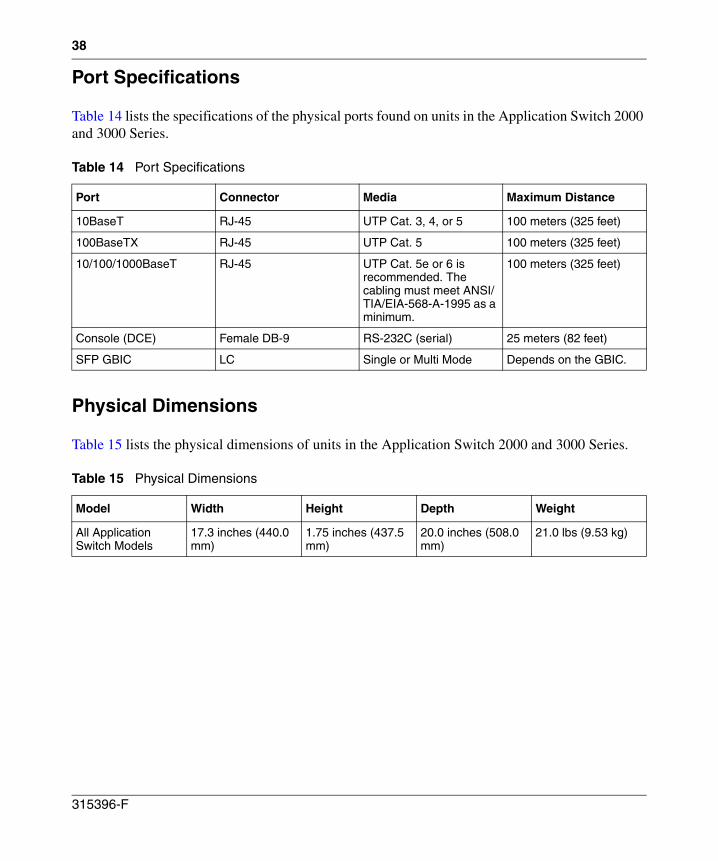
Port Specifications
Table 14 lists the specifications of the physical ports found on units in the Application Switch 2000 and 3000 Series.
Physical Dimensions
Table 15 lists the physical dimensions of units in the Application Switch 2000 and 3000 Series.
Table 14 Port Specifications
Port Connector Media Maximum Distance
10BaseT RJ-45 UTP Cat. 3, 4, or 5 100 meters (325 feet)
100BaseTX RJ-45 UTP Cat. 5 100 meters (325 feet)
10/100/1000BaseT RJ-45 UTP Cat. 5e or 6 is recommended. The cabling must meet ANSI/TIA/EIA-568-A-1995 as a minimum.
100 meters (325 feet)
Console (DCE) Female DB-9 RS-232C (serial) 25 meters (82 feet)
SFP GBIC LC Single or Multi Mode Depends on the GBIC.
Table 15 Physical Dimensions
Model Width Height Depth Weight
All Application Switch Models
17.3 inches (440.0 mm)
1.75 inches (437.5 mm)
20.0 inches (508.0 mm)
21.0 lbs (9.53 kg)
315396-F
39
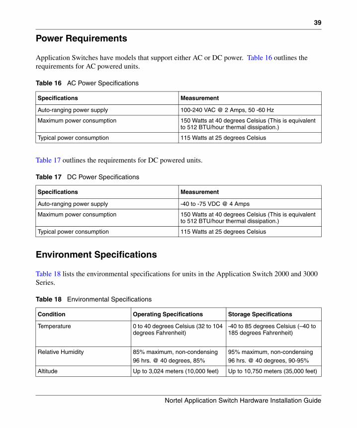
Power Requirements
Application Switches have models that support either AC or DC power. Table 16 outlines the requirements for AC powered units.
Table 17 outlines the requirements for DC powered units.
Environment Specifications
Table 18 lists the environmental specifications for units in the Application Switch 2000 and 3000 Series.
Table 16 AC Power Specifications
Specifications Measurement
Auto-ranging power supply 100-240 VAC @ 2 Amps, 50 -60 Hz
Maximum power consumption 150 Watts at 40 degrees Celsius (This is equivalent to 512 BTU/hour thermal dissipation.)
Typical power consumption 115 Watts at 25 degrees Celsius
Table 17 DC Power Specifications
Specifications Measurement
Auto-ranging power supply -40 to -75 VDC @ 4 Amps
Maximum power consumption 150 Watts at 40 degrees Celsius (This is equivalent to 512 BTU/hour thermal dissipation.)
Typical power consumption 115 Watts at 25 degrees Celsius
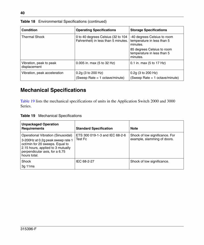
Table 18 Environmental Specifications
Condition Operating Specifications Storage Specifications
Temperature 0 to 40 degrees Celsius (32 to 104 degrees Fahrenheit)
-40 to 85 degrees Celsius (–40 to 185 degrees Fahrenheit)
Relative Humidity 85% maximum, non-condensing
96 hrs. @ 40 degrees, 85%
95% maximum, non-condensing
96 hrs. @ 40 degrees, 90-95%
Altitude Up to 3,024 meters (10,000 feet) Up to 10,750 meters (35,000 feet)
Nortel Application Switch Hardware Installation Guide
40
Mechanical Specifications
Table 19 lists the mechanical specifications of units in the Application Switch 2000 and 3000 Series.
Thermal Shock 0 to 40 degrees Celsius (32 to 104 Fahrenheit) in less than 5 minutes.
-40 degrees Celsius to room temperature in less than 5 minutes.85 degrees Celsius to room temperature in less than 5 minutes.
Vibration, peak to peak displacement
0.005 in. max (5 to 32 Hz) 0.1 in. max (5 to 17 Hz)
Vibration, peak acceleration 0.2g (3 to 200 Hz)(Sweep Rate = 1 octave/minute)
0.2g (3 to 200 Hz)(Sweep Rate = 1 octave/minute)
Table 19 Mechanical Specifications
Unpackaged Operation Requirements Standard Specification Note
Operational Vibration (Sinusoidal)3-200Hz at 0.2g peak sweep rate 1 oct/min for 20 sweeps. Equal to 2.15 hours, applied to 3 mutually perpendicular axis, for a 6.75 hours total.
ETS 300 019-1-3 and IEC 68-2-6 Test Fc
Shock of low significance. For example, slamming of doors.
Shock3g 11ms
IEC 68-2-27 Shock of low significance.
Table 18 Environmental Specifications (continued)
Condition Operating Specifications Storage Specifications
315396-F
41
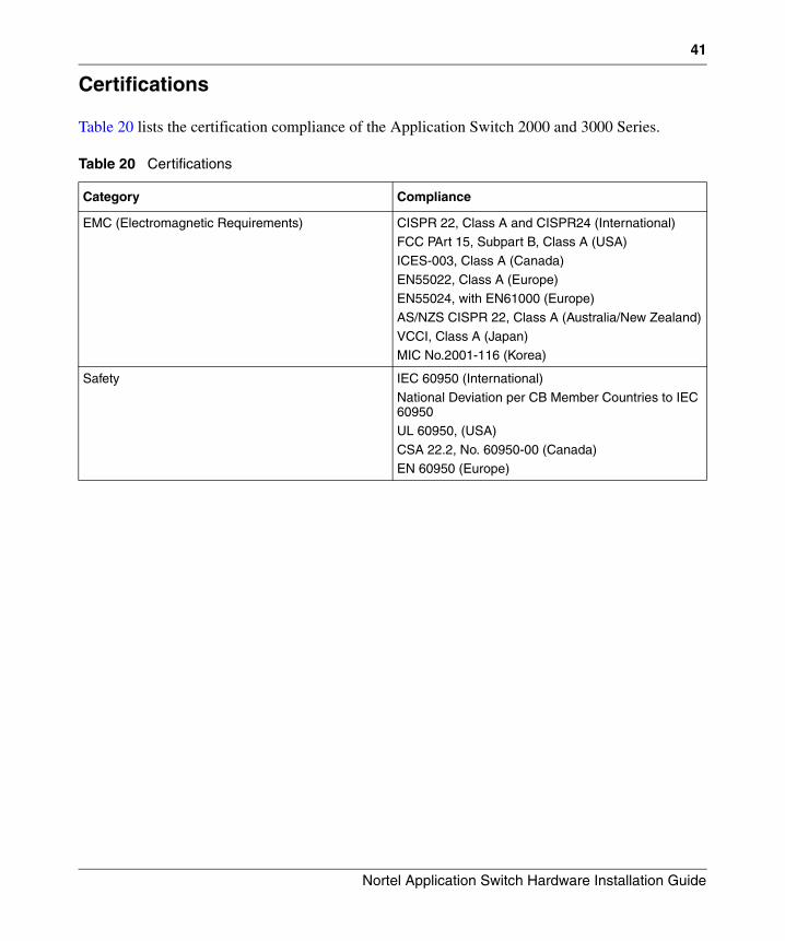
Certifications
Table 20 lists the certification compliance of the Application Switch 2000 and 3000 Series.
Table 20 Certifications
Category Compliance
EMC (Electromagnetic Requirements) CISPR 22, Class A and CISPR24 (International)FCC PArt 15, Subpart B, Class A (USA)
ICES-003, Class A (Canada)
EN55022, Class A (Europe)EN55024, with EN61000 (Europe)
AS/NZS CISPR 22, Class A (Australia/New Zealand)
VCCI, Class A (Japan)MIC No.2001-116 (Korea)
Safety IEC 60950 (International)
National Deviation per CB Member Countries to IEC 60950
UL 60950, (USA)
CSA 22.2, No. 60950-00 (Canada)EN 60950 (Europe)
Nortel Application Switch Hardware Installation Guide
42
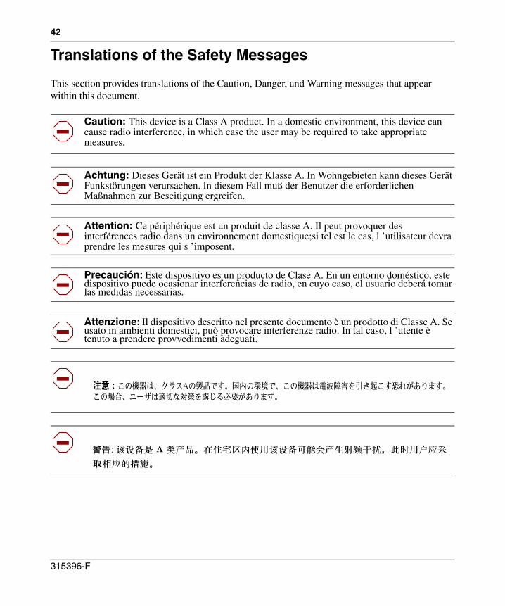
Translations of the Safety Messages
This section provides translations of the Caution, Danger, and Warning messages that appear within this document.
Caution: This device is a Class A product. In a domestic environment, this device can cause radio interference, in which case the user may be required to take appropriate measures.
Achtung: Dieses Gerät ist ein Produkt der Klasse A. In Wohngebieten kann dieses Gerät Funkstörungen verursachen. In diesem Fall muß der Benutzer die erforderlichen Maßnahmen zur Beseitigung ergreifen.
Attention: Ce périphérique est un produit de classe A. Il peut provoquer des interférences radio dans un environnement domestique;si tel est le cas, l ’utilisateur devra prendre les mesures qui s ’imposent.
Precaución: Este dispositivo es un producto de Clase A. En un entorno doméstico, este dispositivo puede ocasionar interferencias de radio, en cuyo caso, el usuario deberá tomar las medidas necessarias.
Attenzione: Il dispositivo descritto nel presente documento è un prodotto di Classe A. Se usato in ambienti domestici, può provocare interferenze radio. In tal caso, l ’utente è tenuto a prendere provvedimenti adeguati.
315396-F
43
Caution: When mounting this device in a rack, do not stack units directly on top of one another in the rack. Each unit must be secured to the rack with appropriate mounting brackets. Mounting brackets are not designed to support multiple units.
Achtung: Wenn diese Einheit in einem Rack montiert wird, muß ein gewisser Abstand zur nächsten Einheit gelassen werden. Jede Einheit muß mit geeignetem Befestigungsmaterial gesichert werden. Das Befestigungsmaterial ist nicht für die gleichzeitige Befestigung mehrerer Einheiten geeignet.
Attention : si vous installez le module dans une baie, ne l’empilez pas directement sur un autre. Chaque module doit être fixé à sa propre baie à l’aide des supports de montage appropriés. Ces supports ne sont pas conçus pour résister à plusieurs modules.
Precaución: Cuando monte este dispositivo en un bastidor, no apile las unidades directamente una encima de otra. Cada unidad debe fijarse en el bastidor con las abrazaderas de montaje adecuadas. Las abrazaderas de montaje no están diseñadas para sostener varias unidades.
Attenzione: se il dispositivo viene installato in un rack, non impilare le unità direttamente una sull’altra. Ogni unità deve essere fissata al rack con le staffe di montaggio appropriate. Le staffe di montaggio non sono state progettate per supportare più unità.
Nortel Application Switch Hardware Installation Guide
44
Danger: Use only power cords that have a grounding path. Without a proper ground, a person who touches the switch is in danger of receiving an electrical shock. Lack of a grounding path to the switch may result in excessive emissions.
Vorsicht: Verwenden Sie nur Netzkabel mit Schutzerdung. Ohne ordnungsgemäße Schutzerdung besteht für Personen, die den Switch berühren, die Gefahr eines elektrischen Schlages. Eine nichtvorhandene Schutzerdung kann zu sehr starken Abstrahlungen führen.
Danger: n ’utilisez que des cordons d ’alimentation équipés de trajet de mise à la terre. Sans mise à la terre adaptée, vous risquez de recevoir une décharge électrique en touchant le commutateur. Par ailleurs, l'absence de trajet de mise à la terre peut générer des émissions excessives.
Peligro: Utilice únicamente cables de alimentación con toma de tierra. De lo contrario, al tocar el interruptor puede recibir una descarga eléctrica. Si no hay un circuito de toma de tierra en el enchufe, puede producirse un exceso de emisiones.
Pericolo: Utilizzare esclusivamente cavi di alimentazione dotati di un percorso per la messa a terra. Senza un ’adeguata messa a terra, chiunque tocchi lo switch corre il rischio di ricevere una scossa elettrica. L ’assenza di un percorso per la messa a terra erso lo switch può comportare un eccesso di emissioni.
315396-F
45
Warning: Fiber optic equipment can emit laser or infrared light that can injure your eyes. Never look into an optical fiber or connector port. Always assume that fiber optic cables are connected to a light source.
Vorsicht: Glasfaserkomponenten können Laserlicht bzw. Infrarotlicht abstrahlen, wodurch Ihre Augen geschädigt werden können. Schauen Sie niemals in einen Glasfaser-LWL oder ein Anschlußteil. Gehen Sie stets davon aus, daß das Glasfaserkabel an eine Lichtquelle angeschlossen ist.
Avertissement: L’équipement à fibre optique peut émettre des rayons laser ou infrarouges qui risquent d’entraîner des lésions oculaires. Ne jamais regarder dans le port d’un connecteur ou d’un câble à fibre optique. Toujours supposer que les câbles à fibre optique sont raccordés à une source lumineuse.
Advertencia: Los equipos de fibra óptica pueden emitir radiaciones de láser o infrarrojas que pueden dañar los ojos. No mire nunca en el interior de una fibra óptica ni de un puerto de conexión. Suponga siempre que los cables de fibra óptica están conectados a una fuente luminosa.
Avvertenza: Le apparecchiature a fibre ottiche emettono raggi laser o infrarossi che possono risultare dannosi per gli occhi. Non guardare mai direttamente le fibre ottiche o le porte di collegamento. Tenere in considerazione il fatto che i cavi a fibre ottiche sono collegati a una sorgente luminosa.
Nortel Application Switch Hardware Installation Guide
46
315396-F
47
Caution: This Product Contains a Lithium Battery. Batteries are not customer replaceable parts. They may explode if mishandled. Do not dispose of the battery in fire. Do not disassemble or recharge.
Achtung: Dieses Produkt enthält eine Lithium-Batterie. Batterien sind nicht Kunde austauschbare Teile. Sie können explodieren, wenn sie mißhandelt werden. Entledigen Sie sich nicht die Batterie im Feuer. Bauen Sie nicht auseinander oder laden Sie neu.
Precaución: Este producto contiene una batería del litio. Las baterías no son piezas reemplazables del cliente. Pueden estallar si están manejadas mal. No disponga de la batería en fuego. No desmonte ni recargue.
Avertissement: Ce produit contient une batterie de lithium. Les batteries ne sont pas les pièces remplaçables de client. Elles peuvent éclater si traitées mal. Ne vous débarassez pas de la batterie en feu. Ne démontez pas ou ne rechargez pas.
Cuidado: Este produto contem uma bateria do lítio. As baterias não são peças substituíveis do cliente. Podem explodir se mishandled. Não disponha da bateria no fogo. Não desmonte nem não recarregue.
Nortel Application Switch Hardware Installation Guide

48
315396-F