Embed Size (px)
Citation preview
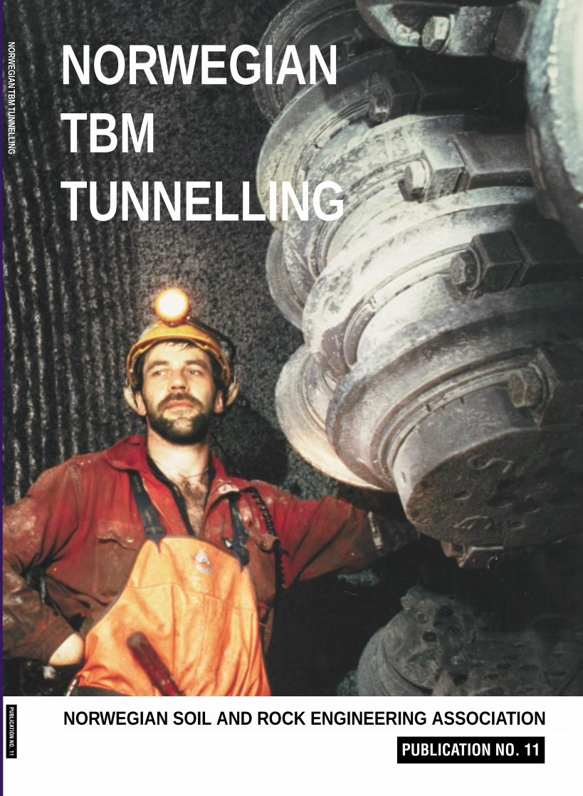
NORWEGIANTBM TUNNELLING
PUBLICATION NO. 11
NORWEGIAN SOIL AND ROCK ENGINEERING ASSOCIATION
PUBLICATION NO. 11NO
RWEG
IAN TBM TUNNELLING
3
NORWEGIAN TBM TUNNELLING
30 YEARS of EXPERIENCE with TBMs in NORWEGIAN TUNNELLING

4
NORWEGIAN SOIL AND ROCK ENGINEERING ASSOCIATION
INCORPORATING
NORWEGIAN TUNNELLING SOCIETYNORWEGIAN GEOTECHNICAL SOCIETYNORWEGIAN ROCK MECHANICS GROUP
REPRESENTS EXPERTISE IN
• Hard Rock Tunnelling techniques• Rock blasting technology• Soft soil engineering• Marine and offshore geotechnology• Rock mechanics and engineering geology
USED IN THE DESIGN AND CONSTRUCTION OF
• Hydroelectric power development, including:- water conveying tunnels- unlined pressure shafts- subsurface power stations- lake taps- earth and rock fill dams
• Transportation tunnels• Underground storage facilities• Heavy foundations on soft ground• Foundations of offshore constructions• Underground openings for public use
SECRETARIAT:NORWEGIAN TUNNELLING SOCIETY NFFP. O. Box 2312, SolliN-0251 Oslo, Norwaye-mail: [email protected]
5
NORWEGIAN TBM TUNNELLING
30 YEARS of EXPERIENCE with TBMs in NORWEGIAN TUNNELLING
Publication No. 11
NORWEGIAN SOIL AND ROCKENGINEERING ASSOCIATION
NORWEGIAN TUNNELLING SOCIETY, NFF,

6
© NORWEGIAN TUNNELLING SOCIETY 1998
ISBN 82-991952-1-7
Picture credits: Cover page: Statkraft Anlegg AS
Print: Hansen Grafiske, Oslo
7
CONTENTSPreface 9
1 Arnulf HansenThe History of TBM Tunnelling in Norway 11
2 O. T. Blindheim and Amund BrulandBoreability Testing 21
3 Amund BrulandPrediction Model for Performance and Costs 29
4 Odd AskilsrudDevelopment of TBM Technology for Hard Rock Conditions 35
5 O. T. BlindheimEarly TBM Projects 43
6 Thor Skjeggedal and Karl Gunnar HolterThe VEAS Project - 40 km Tunnelling with Pregrouting 53
7 O. T. Blindheim, Erik Dahl Johansen and Arild HegrenæsBored Road Tunnels in Hard Rock 57
8 Jan Drake and Erik Dahl JohansenThe Svartisen Hydroelectric Project - 70 kilometres of Hydro Tunnels 63
9 Arne Myrvang, O. T. Blindheim and Erik Dahl JohansenRock Stress Problems in Bored Tunnels 71
10 Thor Skjeggedal and Karl Gunnar HolterSix Case Histories 79
11 Steinar Johannessen, Odd G. Askilsrud and Amund BrulandThe Meråker Project - 10 km of Tunnel in 12 Months 85
12 Tom MyranNorwegian TBM Tunnelling. Health and Safety. 91
13 Hallvard HolenTBM vs. Drill & Blast Tunnelling 95
14 Amund BrulandFuture Demands and Development Trends 99
9
PREFACE
This publication is the eleventh volume in a series of books presenting 30 years of Norwegianexperience in tunnelling technology. The publications are prepared by the NorwegianTunnelling Society (NFF).
The scope of the present volume is TBM tunnelling in Norway. The first TBM project executedin Norway dates back to 1967. It was called promising, in spite of low penetration and highcosts. Later TBM development is closely connected to the development of high performancemachines, increased thrust per cutter and improved bit technology. James S. Robbins andRobbins machines played an important role in this process. It should also be mentioned that thefirst attempt to construct a TBM in Norway was made in 1922 by Mr. I. Bøhn. He held a patentsince 1917 and brought his machine as far as to the testing stage.
The underground has been utilised during centuries also in this country. Systematic mining ofores and minerals in Norway dates back to the sixteenth century. Being a mountainous region,tunnelling was in second hand closely linked to the development of communications. Ourtunnelling for railroads started in the latter part of the 19th century.
Thanks to the topography, precipitation and water storing possibilities, and the need for energy,hydropower development has been an important construction segment from 1945 up to say1990. A major part of our TBM-operations were linked to this development from 1965 onwards.Additional tunnelling for water supply and sewage handling has also been of importance duringthe same period, whereas road tunnels always used to play a less important part of the TBMmarket.
Due to a combination of rock quality, well developed drilling equipment, qualified tunnellersand well trained designers, Norway used to be a typical «drill and blast»-country. A competitivemarket situation, however, is the golden key to new cost efficient methods. Thus hard rock tunnel boring was introduced and during the years, through close co-operation between supp-liers and contractors, the method was honed to perfection.NFF - the Norwegian Tunnelling Society has felt an obligation to share with friends and colleagues what was learnt during the process. NFF does hope that this book may contribute to further development of the TBM technology.
Oslo November 1998
The Editorial Committee

10

8
APPENDICES
A The Norwegian Tunnelling Society
B NFF’s International Support Group
C Presentation of the Editorial Committee and the Authors
D Presentation of the first attempt to construct a Norwegian TBM
E Books and Videos in English available from NFF
11
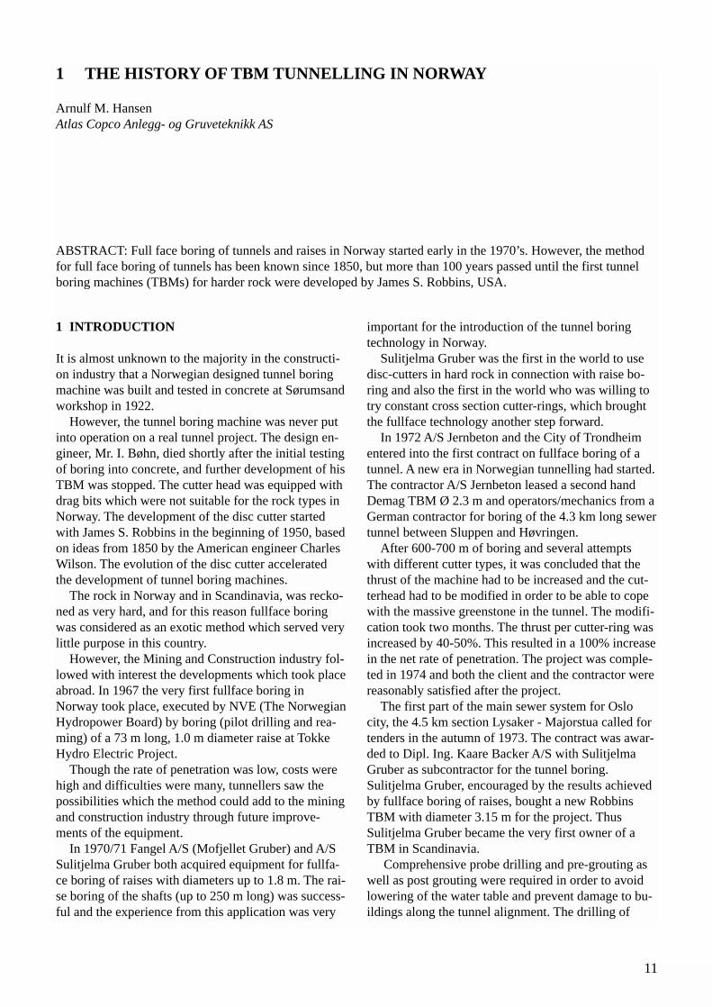
1 INTRODUCTION
It is almost unknown to the majority in the constructi-on industry that a Norwegian designed tunnel boringmachine was built and tested in concrete at Sørumsandworkshop in 1922.
However, the tunnel boring machine was never putinto operation on a real tunnel project. The design en-gineer, Mr. I. Bøhn, died shortly after the initial testingof boring into concrete, and further development of hisTBM was stopped. The cutter head was equipped withdrag bits which were not suitable for the rock types inNorway. The development of the disc cutter startedwith James S. Robbins in the beginning of 1950, basedon ideas from 1850 by the American engineer CharlesWilson. The evolution of the disc cutter acceleratedthe development of tunnel boring machines.
The rock in Norway and in Scandinavia, was recko-ned as very hard, and for this reason fullface boringwas considered as an exotic method which served verylittle purpose in this country.
However, the Mining and Construction industry fol-lowed with interest the developments which took placeabroad. In 1967 the very first fullface boring inNorway took place, executed by NVE (The NorwegianHydropower Board) by boring (pilot drilling and rea-ming) of a 73 m long, 1.0 m diameter raise at TokkeHydro Electric Project.
Though the rate of penetration was low, costs werehigh and difficulties were many, tunnellers saw thepossibilities which the method could add to the miningand construction industry through future improve-ments of the equipment.
In 1970/71 Fangel A/S (Mofjellet Gruber) and A/SSulitjelma Gruber both acquired equipment for fullfa-ce boring of raises with diameters up to 1.8 m. The rai-se boring of the shafts (up to 250 m long) was success-ful and the experience from this application was very
important for the introduction of the tunnel boringtechnology in Norway.
Sulitjelma Gruber was the first in the world to usedisc-cutters in hard rock in connection with raise bo-ring and also the first in the world who was willing totry constant cross section cutter-rings, which broughtthe fullface technology another step forward.
In 1972 A/S Jernbeton and the City of Trondheimentered into the first contract on fullface boring of atunnel. A new era in Norwegian tunnelling had started.The contractor A/S Jernbeton leased a second handDemag TBM Ø 2.3 m and operators/mechanics from aGerman contractor for boring of the 4.3 km long sewertunnel between Sluppen and Høvringen.
After 600-700 m of boring and several attemptswith different cutter types, it was concluded that thethrust of the machine had to be increased and the cut-terhead had to be modified in order to be able to copewith the massive greenstone in the tunnel. The modifi-cation took two months. The thrust per cutter-ring wasincreased by 40-50%. This resulted in a 100% increasein the net rate of penetration. The project was comple-ted in 1974 and both the client and the contractor werereasonably satisfied after the project.
The first part of the main sewer system for Oslocity, the 4.5 km section Lysaker - Majorstua called fortenders in the autumn of 1973. The contract was awar-ded to Dipl. Ing. Kaare Backer A/S with SulitjelmaGruber as subcontractor for the tunnel boring.Sulitjelma Gruber, encouraged by the results achievedby fullface boring of raises, bought a new RobbinsTBM with diameter 3.15 m for the project. ThusSulitjelma Gruber became the very first owner of aTBM in Scandinavia.
Comprehensive probe drilling and pre-grouting aswell as post grouting were required in order to avoidlowering of the water table and prevent damage to bu-ildings along the tunnel alignment. The drilling of
1 THE HISTORY OF TBM TUNNELLING IN NORWAY
Arnulf M. Hansen Atlas Copco Anlegg- og Gruveteknikk AS
ABSTRACT: Full face boring of tunnels and raises in Norway started early in the 1970’s. However, the methodfor full face boring of tunnels has been known since 1850, but more than 100 years passed until the first tunnelboring machines (TBMs) for harder rock were developed by James S. Robbins, USA.
12
probe holes and holes for grouting were carried out byhand held equipment.
The tunnel boring started in November 1974 andwas successfully completed in June 1976. There werefew technical problems with the equipment, the advan-ce rate was good and the cutter costs were low in theCambro-Silurian formation.
The utilisation of the TBM at the project was lowbecause of the comprehensive probe drilling and grou-ting which was necessary to meet with the contract re-quirements.
It was recognised that on future similar TBM pro-jects it would be necessary to incorporate specialequipment for probe drilling and drilling of groutholeson the TBM.
The experience gained from this project was utilisedon the remaining 35 km of the Western OslofjordSewer Project.
Encouraged by the promising results from the twofirst TBM tunnels in this country, the largest contrac-tors decided to promote tunnel boring as an alternativeto Drill & Blast. In 1982, 10 years after the initial full-face boring in Norway, a total of 22 tunnel projectswere underway or had been completed.
After the sewer project in Oslo, Sulitjelma Gruber’smachine was used in Fosdalen Bergverk for the boringof a main haulage tunnel at an 800 m deep level in themine.
Initially the boring went well, but on the way thetunnel alignment was changed to bore into very toughand massive quartz keratophyre, which resulted in lowrate of progress and advance rates and very high cuttercosts.
The boring was terminated after 670 m and theequipment moved after rebuilding to the EidfjordProject in 1977. The diameter was extended from 3.15m to 3.25 m and the size of the cutters changed from12” to 14”, in order to cope with the granitic gneissformations at the Floskefonn tunnel.
Of a total length of approximately 4.6 km, the first1.8 km of the Floskefonn transfer tunnel at EidfjordHEP consisted of a granitic gneiss with UCS up to 270MPa. The rest of the tunnel consisted more or less of“forgiving” rock, phyllite with some quartz lenses.
350 m into the tunnel and after three Main Bearingfailures, Sulitjelma Gruber decided to pull out of thetunnel and the contract with NVE. At that time therewas a business down turn in the mining industry gene-rally with low copper prices. Due to this and togetherwith the financial setbacks at the Oslo Sewer Project(the Main contractor went bankrupt), Sulitjelma minesdecided to conclude their contracting activities and toconcentrate on mining. The machine was sold to anAustrian contractor for a project in Africa, and hassuccessfully completed many tunnels since then.
Contractor Høyer-Ellefsen took over Floskefonntunnel project. The remaining part of the tunnel sectionwith granitic gneiss formations was excavated by Drill& Blast and a second hand Wirth TBM Ø 2.53 m wasthen used to bore the balance of the tunnel consistingof phyllite.
2 THE ROLE OF THE NORWEGIAN UNIVER-SITY OF SCIENCE AND TECHNOLOGY(NTH) IN THE DEVELOPMENT OF FULL-FACE TUNNEL BORING
It has to be mentioned that NTH (now NTNU), repre-sented by the Department of Building andConstruction Engineering, has been a prime force forthe method and for the understanding and develop-ment of tunnel boring machines in hard rock. At anearly stage NTH realised the possibilities and advanta-ges fullface boring would give to the contractors andto the clients.
In cooperation with contractors, machine suppliersand tunnel owners, NTH has used the tunnels as fullscale laboratories from the time the method was intro-duced in Norway, and made a comprehensive collecti-on and systematizising of boring information by usingengineering students.
The development of NTH’s prognosis model from1/76 until today’s 1/94 has brought about an under-standing for TBM, geology and rock parameters whichare of vital importance for estimating advance ratesand costs.
NTH’s development of the model has formed thebasis for better understanding and planning of fullfaceboring projects and has given the contractors a goodtool for detail calculations and scheduling for TBMprojects, or when comparing TBM and conventionalDrill & Blast. The model is being used for planningand bid purposes on several projects abroad.
The first prediction model was developed and pu-blished in 1976 in cooperation between the Departmentof Construction Engineering, and the Department ofGeology at NTH (the Norwegian University of Scienceand Technology).
3 TUNNEL BORING AT AURLAND HYDRO ELECTRIC PROJECT
In 1977-78, the contractor Ing. Thor Furuholmen A/Swith technical support from the Swiss contractorPrader AG bored a 6.2 km long transfer tunnel at theremote Aurland HEP with a Robbins TBM 3.5 m dia-meter. The rock was mostly phyllite with quartz lensesand sections consisting of massive, abrasive sandstone.
13
The boring operation was very successful. No rocksupport was required during boring and the need forpermanent rock support was minimal. The unit costper meter tunnel excavated was somewhat higher thancalculated for Drill & Blast, but the reduced construc-tion time from one adit only made the TBM tunnelproject come out as a great winner.
The Aurland project became an important cornerstone for the further development of NTH’s predictionmodel. Here, for the very first time, NTH also recor-ded the effects of angle between foliation and tunnelaxis on the net rate of penetration.
4 THE DEVELOPMENT OF THE WESTERN OSLOFJORD REGIONAL SEWAGE PROJECT
The City of Oslo, together with the neighbouring mu-nicipalities of Bærum and Asker, established a jointlyowned sewage treatment plant in the period 1974-1981.The scheme comprises connecting tunnels with diame-ters ranging from 3.0 m to 3.5 m, nearly 40 km in totallength.
In 1970 when the Prestudy Report for the projectwas presented, it was assumed that all tunnels were tobe excavated by Drill & Blast methods.
However, the 1973 Feasibility Study Report conclu-ded that an alternative method based on TBM shouldbe requested in addition to tenders based on Drill &Blast.
In 1976, after the successful completion of the firstsection of the main sewage tunnel system (Lysaker -Majorstua), the tender documents for the remainingcontracts specified that all major tunnels were to beexcavated by TBMs. Drill & Blast method would notbe accepted. In a time span of six years the approachof the owner and his consultants changed from 100%conventional to 100% TBM boring.
The tunnels were bored with seven TBMs from fourdifferent manufacturers with quite different concepts.At one time, a total of six machines were in operationat the project - one Wirth, two Bouygues, two Robbinsand one Atlas Copco.
The experience gained from the first tunnel drive onthe project was used as input for the tender documentspecifications for later contracts for the same project in1976 and 1977. The owner made strict requirements forprobing and pregrouting in order to avoid or minimise da-mage due to settlement, caused by lowering of the groundwater table. The contractors had to provide and demon-strate mechanised equipment and methods for efficientprobing and pregrouting. This became the most extensiveprobing and grouting program ever executed in connecti-on with TBM operations anywhere in the world.
5 HARDER AND MORE MASSIVE ROCK IS BEING BORED
Norway is generally considered to provide some of thetoughest hard rock challenges in the world. With fewexceptions, the first TBM projects in Norway startedout in the relatively easy greenschists, greenstone, sha-le, limestone, phyllites and micaschists. Later, tunnelsin Precambrian rocks, granites and gneiss have beenbored.
The breakthrough for hard rock tunnel boring camein the period 1981-1984 with the accomplishment ofthe 8 km long, 3.5 m diameter transfer tunnel inGlommedal at Ulla Førre Hydro Electric Project.Encouraged by the results from the tunnel boring inKleådalen at the Aurland project, NVE decided in1980 to purchase a new 3.5 m dia TBM to bore theGlommedal transfer tunnel.
The area contained massive granite and gneiss for-mations with up to 210 MPa unconfined compressivestrength. In fact, the rock on this project was so massi-ve, that the NTH (the Norwegian University ofScience and Technology, now NTNU) predictor modelwas revised to include the fracture class 0 (zero). TheRobbins TBM 117-220 worked for 2.5 years to cutthrough the massive rock on the 8,022 m diversiontunnel.
The same TBM 117-220 later drove a 9.2 km diver-sion tunnel through granitic gneiss at Kobbelv HydroElectric Project, followed by 9.3 km at Storjord siteand 6.2 km at Trollberget site, Svartisen Project.
In November 1991 the TBM set outstandingNorwegian tunnelling performance records atVegdalen Diversion tunnel, Svartisen project: bestshift - 44.2 m, best day - 81.8 m, best week - 421.2 mand best month - 1,176.5 m, averaging more than 200m per week in the micaschist and micagneissformations.
Owned and operated by Statkraft (formerly NVE)the TBM has bored a total of 32.7 km of tunnel on fourprojects, all in hard rock formations. This “oldtimer” isthe TBM that has bored the most tunnel metres inNorway and Scandinavia so far, and is also included inthe Robbins TBM Honor Roll.
6 TBM INCLINE SHAFT BORING
Boring inclines with TBM + ABS (anti-backslip-sys-tem) was first used in Norway in 1980 by contractorHøyer-Ellefsen in cooperation with the Swiss contrac-tor Murer AG, at Sildvik Hydro Electric Project nearCity of Narvik. A 45 degrees, 760 m long x 2.53 m di-ameter pressure shaft was completed with a Wirth
14
TBM in six months, inclusive assembly and disassem-bly of the equipment. Average advance rate of 45 mper week was achieved.
The performance of the incline borer met with theexpectations and encouraged the contractor Astrup-Høyer AS in 1983 to purchase an Atlas Copco Jarva3.2 m diameter TBM to bore a 1,250 m long, 41 de-gree pressure shaft at Tjodan Hydro Project.
In 1985 the same contractor used this TBM to borethe 1,370 m long penstock with 100% inclination atNyset-Steggje HEP. The shaft was completed in sevenmonths, including downtime due to a main bearing fail-ure. The main bearing of the TBM was changed in theshaft, approximately 450 m from the start portal.
The rock bored at Tjodan and Nyset-Steggje consis-ted of massive granite and granitic gneiss. Shaft boringof longer pressure shafts with TBMs proved to be avery good alternative to conventional Drill & BlastAlimak raising, especially when the pressure shaft ison the critical path.
7 ROCK BURST AND SPALLING CHALLEN-GES AT KOBBELV HYDRO ELECTRIC PROJECT
During TBM boring in granitic gneiss at KobbelvHydro Electric Project in 1984, extreme rock burst andspalling problems occurred, caused by high horizontalin-situ stresses.
Approximately 1,700 m into the 6.25 m diameterTverrelvdal headrace tunnel intensive bursting andspalling occurred. Extensive and systematic rock sup-port were required to safeguard men and equipment.Rock bolts with plates were installed immediately be-hind the TBM front supports from the TBM workingplatforms. After about 200 m the rock burst and thespalling decreased gradually as the rock overburdenincreased, thus counteracting the effect of the horizon-tal stresses. The average daily production rates overthe 200 m section dropped to approximately 6 m, andthe rock stability problems increased the constructionschedule by about two months.
Intensive spalling occurred as well during boring ofthe first 1,000 m section of the 9.2 km long 3.5 m dia-meter nearby Reinoksvatn transfer tunnel. High tan-gential stress concentrations in the roof and in the in-vert, caused by the high horizontal stresses in the area,required immediate, extensive and systematic rocksupport. Rock bolts, straps and netting, and concretingof the invert were used to stabilise the track. As for theTverrelvdal tunnel, the spalling decreased as the rockoverburden increased. Average weekly productionover the first 1,000 m slowed to 52 m per week as
opposed to 120 m per week in the remaining part ofthe tunnel, and the problems added eight weeks to theconstruction schedule.
The contractor/owner NVE (The Norwegian StatePower Board) concluded that a better advance prein-vestigation and understanding of rock mechanics andstress conditions at Kobbelv would have resulted inbetter forecasting, and would have eased the challen-ges and probably reduced time loss to the half. NVEand renowned rock mechanic experts were also of theopinion that Drill & Blast tunnelling would have crea-ted even worse spalling problems and damage to thetunnel surface over longer stretches than for TBM bo-ring, due to the impact from the blasting.
8 TBM FOR ROAD TUNNELLING
For the construction of the Svartisen Hydro ProjectNVE, the Norwegian Water Resources and ElectricityBoard (now Statkraft) needed road access to theWestern part of the project. In 1983 it was decided tobuild a 7.6 km single lane road tunnel with meeting ni-ches at every 300 m, and a 6.25 m diameter leased, se-cond hand TBM was commissioned to drive a 4.3 kmsection of the tunnel between Kilvik and Glomfjord.
After the project was started, government authoriti-es involved upgraded the road standard from a single-lane to a two-lane highway as part of the highway sys-tem along the coast of Norway. The TBM driven sec-tion therefore was later slashed out from Ø 6.25 (30.7m2) to 52.5 m2 to meet with the T8-standard require-ments of the Road Department.
In the period 1984-1986 The Norwegian PublicRoad Administration built two-lane dual road tunnels,3.2 + 3.7 km long, through Fløyfjellet, City of Bergen,as part of a bypass motorway system by using a 7.8 mdiameter Robbins TBM with backup for tracklessmuck haulage by regular dump trucks.
The TBM was named “Madam Felle” after a locallywell-known lady running a beer pub in the “good olddays” in Sandviken, an old part of Bergen. Besidestunnelling advance rates, emphasis was also put on theenvironmental aspects of TBM boring vs. Drill &Blast because of the dense population along the tunnelalignment, including hospitals near the tunnel portalsand exits. The tunnel boring was a success in the hardgranitic gneiss formations. However, slashing out thetwo lower corners by Drill & Blast to meet with themotorway standard was time consuming.
Later, in 1987, the TBM was enlarged from 7.8 m to8.5 m diameter to reduce slashing and drove a 850 mlong road tunnel which was parallel and close to anexisting road tunnel in Eidsvåg, a suburb of Bergen
15
city. Boring of the tunnel was almost a must in order tomaintain the traffic in the construction period. At 8.5m diameter the lower corners still had to be blasted.
In order to avoid the time consuming and costlyslashing out of corners for the most of the road tunnelsto be built in Norway, a TBM diameter of 9.3 - 9.5 mis needed.
In 1996 Statkraft Anlegg AS, who is playing an ac-tive role in the Norwegian TBM tunnelling effort do-mestically as well as internationally, purchased fromthe Swedish contractor Kraftbyggarna two of the mostpowerful large diameter TBMs ever built; two AtlasCopco MK 27 TBMs with diameters Ø 6.5 and 9.1 m.The diameter for both TBMs can be extended to 10-12m depending on the rock formations to be bored.
Statkraft Anlegg in cooperation with the NorwegianPublic Road Administration and Department ofBuilding and Construction Engineering at theNorwegian University of Science and Technology(NTNU) started in 1996 a development program forbuilding of TBM bored road tunnels in Norway insuch a way that the road bed and tunnel installationsbehind the TBM is finished at the breakthrough.
9 UPGRADING OF AN EXISTING HYDRO POWER PLANT
In 1986 the owner of Nedre Vinstra Hydro Plant calledfor bids for extension of the existing power plant andconnecting tunnel system in order to double the powerproduction.
The plan included enlargement from 32 to 52 m2
cross section of the existing headrace tunnel by slash-ing out the invert over the whole length of 17 km. Tominimise lost revenue during plant shut down, thework had to be completed within one or two summerseasons, using large crews to drive simultaneouslyfrom five existing access tunnels.
During bidding for the job, the VSF Group, a jointventure of AS Veidekke and Selmer Furuholmen AS,suggested an attractive bid alternative. The VSF Groupproposed to drive a nearly parallel headrace tunnelusing two second-hand TBMs in the phyllite and sand-stone formations. This scheme would enable the powerstation to remain in operation during the constructionof the tunnel. The solution would cut power stationdowntime from a minimum of six months to onemonth, and nearly eliminate the need for rock support.New TBMs were not considered because of the 4-5months required tunnel start up. Two existing Robbinsmachines (Models 148-212 and 148-213) successfullyused by the contractor A/S Jernbeton on the Brattsetand Ulset HEPs, were applicable and readily available.
The machines were upsized to 4.75 m diameter.The two TBMs were started from a single adit ap-
proximately halfway between the reservoir and thepressure tunnel, and the machines bored in oppositedirections, with a common tip station for the mucktrain.
The project proved to be very successful, and wascompleted six months ahead of schedule.
At the bidding stage, the TBM alternative for theheadrace tunnel was calculated to cost about 15%more than the Drill & Blast slashing out of the invert.However, the income from electricity generation du-ring the construction of the TBM headrace tunnelmore than offset the extra cost of construction.
10 FIVE TBMs ON SVARTISEN HYDRO ELEC-TRIC PROJECT
In cooperation with Statkraft, Robbins introduced in1988 the High Performance TBMs, using 483 mm(19”) cutters. The three first HP TBMs thus ever built,TBM 1410-251 (Ø 4.3/5 m), TBM 1410-252 (Ø 4.3 m)and TBM 1215-257 (Ø 3.5 m) bored 13.8 km, 11.8 kmand 8.2 km tunnels respectively at Trollberget job site,Svartisen Project.
By this development, the cutters, TBM and theTBM performance were taken to a new level, and gavethe TBM industry an improved tool for boring hard tovery hard rock formations.
On the west side of the Svartisen glacier, Statkraftwas using the 8.5 m diameter Robbins machine,“Madam Felle”, the veteran of the twin highway tun-nels in Bergen and Eidsvaag, for driving a 7.3 km longincline pressure tunnel (1:13.5) with trackless haulageof muck. A Statkraft designed turntable was used forturning the trucks right behind the backup, instead ofproviding turning niches.
The TBM from Ulla Førre and Reinoksvatn(Kobbelv Hydro Project), Robbins model 117-220 (Ø3.53 m) first drove a 9.3 km near-the-surface guttertunnel on the West side of the glacier and was thenmoved to Trollberget where it bored another 6.2 kmtunnel.
The Main Bearings for the HP TBMs supplied toSvartisen are of the Tri-axial type. The change in thelate eighties from Tapered Roller Bearings to Tri-axialMain Bearings in the TBM industry has improved theutilisation of the machines due to improved load cha-racteristics and bearing life.
Another big improvement is the new style wedgelock cutter housings that were introduced by Robbinsat Trollberget job site, first time ever. This cutter hou-sing design is superior to any other cutter housing and
12 NORWEGIAN CONTRACTORS WITH TBM EXPERIENCE
16
became instantly the industry standard, leading to im-proved cutter life and less cutter changes.
The development and introduction of the Robbins19” (483 mm) cutters rated at 312 kN/cutter was an- other significant step forward in hard rock boring andenabled the HP-machines to operate at 40-50% higherthrust per cutter compared to the standard TBMs fittedwith 17” cutters.
Statkraft tested different type cutters and cutter-rings from other manufacturers (Wirth, Sandvik) aswell at the Svartisen project, including a new concept,the “Norway-cutter” designed by Stein Narvestad. Thesplit cutter-ring design allowed cutter-rings to bechanged at the face. The conclusion from the fairly li-mited testing at selected cutter positions was that thisconcept worked and was an interesting alternative forcutters in abrasive rock formations. However, furthermodifications were needed, and there was still roomfor improvements in the design of the retainer device,holding the cutter-ring in place.
11 RECORD PERFORMANCE AT MERAAKER HYDRO ELECTRIC PROJECT
In August 1992 Merkraft, a joint venture of Eeg-Henriksen Anlegg AS and AS Veidekke, completed theboring of a 10 km transfer tunnel at Meraaker HydroElectric Project with a 3.5 m diameter Robbins High-Performance TBM in less than 11 months. The tunnelboring was finished six months ahead of schedule. Inthe first full month of operation the TBM achieved thefastest start-up of any Robbins TBM on record by bo-ring 1,028.9 m.
Merkraft set outstanding national performance re-cords along the way with the HP TBM working in geo-logy ranging from hard, massive metagabbro, withUCS of 300 MPa and graywacke and sandstone appea-ring as mixed face conditions to relatively soft phyllite.
• Best shift (10 hrs.) 69.1 m• Best day (two 10 hr. shifts) 100.3 m• Best week (100 shift hours) 426.8 m• Best month (430 shift hours) 1358.0 m• Average weekly advance rate 253.0 m
Projects abroad:Statkraft 16 kmNOCON (Veidekke-Selmer) 19 kmNOCON/Eeg-Henriksen/Statkraft 9 kmJernbeton (Astrup-Høyer) 5 kmCompleted, under construction or under start up: 49 km(1994 - )
As of 1997, the total length of TBM bored tunnels inScandinavia, completed or under construction is 321km of which 258 km have been bored in Norway.
Projects in Norway:Statkraft 102 kmHøyer-Ellefsen * 18,643 mAstrup-Aubert * 12,050 mAstrup-Høyer * 1,370 mJernbeton * 34,510 mAker Entreprenør * 6,350 m 73 km(*: now Veidekke)Furuholmen (now Selmer) 35 kmVSF (Veidekke/Selmer-Furuholmen) 17 kmHordaland Vegkontor/State Road Dept. 8 kmKruse Smith 8 kmSulitjelma Gruber 5 kmMerkraft (J.V. of Veidekke and Eeg-Henriksen) 10 kmCompleted (1972-1992) 258 km
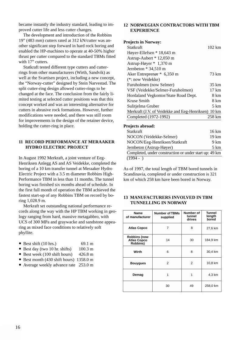
13 MANUFACTURERS INVOLVED IN TBM TUNNELLING IN NORWAY
Nameof manufacturer
Number of TBMssupplied
Number oftunnel drives
Tunnellength bored
Atlas Copco
Robbins (nowAtlas Copco
Robbins)
Wirth
Bouygues
Demag
7 8 27,6 km
14 30 184,9 km
30,4 km
10,8 km
4,3 km
8
2
1
6
2
1
258,0 km4930
17
14 NORWEGIAN TBM CONTRACTORS ABROAD
Jernbeton AS was the first Norwegian contractor ope-rating a TBM abroad. As sub-contractor to Skanska,in the period 1985-86 a 4.5 km section of theKymmen Hydro tunnel in Sweden was bored.Jernbeton used its 4.53 m diameter Robbins TBM148-212 in gneiss and granitic rocks.
In August 1992, after the Meraaker Hydro Projectwas completed, a 20 year period of tunnel boring inNorway had come to a temporary stop, due to lack ofprojects. Contractors with TBM expertise had to lookfor projects abroad.
In 1993 Merkraft sold the Robbins HP TBM 1215-265 to a foreign contractor for a project in the MiddleEast. The machine was upsized from 3.5 m to 4.23 mdiameter. However, Nocon (50/50 owned by Selmerand Veidekke) in cooperation with Eeg-Henriksen andStatkraft Anlegg operated this TBM as sub-contractorto the main contractor. The boring of the 9 km sectionof the tunnel was successfully completed in the begin-ning of 1997.
Statkraft Anlegg AS entered into a cooperationagreement with the Joint Venture CNO/WBH in 1994,for boring of 6.5 km of the 6.7 km long 3.5 m diame-ter Midmar Tunnel in South Africa. The Robbins HighPerformance TBM Ø 3.5 m (with 19” cutters) fromSvartisen Project was used. The drive, which began inbeginning of February 1995, is part of the first phaseof the Umgeni Water project to provide water to thePietermaritzburg area, west of Durban. StatkraftAnlegg provided the TBM and technical support forthe Midmar drive, including the TBM operating crew,cutter shop man, supervisor and manager.
The Midmar tunnel encountered some of the har-dest rock ever bored with a TBM. One dolerite sam-ple tested at 420 MPa. The tough dolerite comprisedhalf of the tunnel length. Cutter changes consumed al-most half of the available time, and caused the driveto fall 10 weeks behind schedule. Statkraft Anleggworked closely with Atlas Copco Robbins in develo-ping a new extra heavy duty cutter-ring to sustain thecutter loads required and the impact from open jointsfor this particular drive. The new cutter-rings reducedcutter consumption by 50% and put Midmar back ontrack. The breakthrough came on schedule end ofFebruary 1996.
The Midmar Tunnel used an extensible conveyormucking system for the entire TBM bored tunnellength of 6.5 km and Statkraft Anlegg became the firstNorwegian contractor to use a Continuous ConveyorSystem.
In August 1997 Statkraft Anlegg entered into a lea-se agreement with Leighton Kumagai Joint Venture
for the use of the Robbins HP TBM 1215-257 for bo-ring of a 4.5 km section of a 12 km long water supplytunnel in Hong Kong. The contract includes technicalservices from Statkraft Anlegg for the duration of thetunnel boring. The diameter of the TBM will be exten-ded from 3.5 m to 3.84 m. The boring start up wasscheduled for January 1998.
Statkraft Anlegg, in joint venture with JaiprakashIndustries Limited India, is currently operating a 8.3 mdiameter Open Robbins Hard Rock TBM at Dul HastiProject in Kashmir, India. Approximately 1,600 m ofthe 6.5 km section of the headrace tunnel was comple-ted by a French Joint Venture before it pulled out ofthe project in 1993 for security reasons. Statkraft has acrew of 15 people on the project.
In August 1997, Statkraft Anlegg successfully com-pleted a 110 m long, 1.8 m diameter raise at Dul Hastiwith an old Robbins 61R raise drill that was takenover from the J.V. through the client, and thatSulitjelma Gruber purchased in 1971 new fromRobbins.
Statkraft Anlegg has become one of the most ag-gressive hard rock TBM contractors world-wide, andthey are currently bidding on several tunnel projects abroad.
The Norwegian Construction Group (NOCON) sig-ned a contract in January 1996 with the main contrac-tor Astaldi/SAE Joint Venture for boring of a 4 kmheadrace tunnel and an approximately 15 km longtransfer tunnel as subcontractor at Pont VentouxProject in northern Italy, close to the French border.
On this project NOCON is currently operating tworefurbished “old timer” Robbins TBMs, open hardrock type, Ø 4.75 m leased from two different owners.Continuous Conveyor Systems are used for mucktransportation for both TBMs. After boring approxi-mately 2,400 m of the transfer tunnel from F2 site, atotal water inflow in the range of 20 m3 per minuteover some 900 m bored, seems to be the most difficulttask to handle on this tunnel project. Railbound muckhaulage under such circumstances would not havebeen feasible.
15 THE NORWEGIAN ROCK BLASTING MUSEUM
To honour the Norwegian Tunnelling Society for itscontribution to the success of hard rock tunnel boring,Atlas Copco Robbins in November 1997 donated theveteran Robbins TBM 81-118 to the Norwegian RockBlasting Museum. The 2.59 m dia TBM, still in goodoperating condition, was manufactured by Robbins in1965, and was the 18th machine built.
18
19

20
21
1 INTRODUCTION
The performance of tunnel boring machines is depen-dent on the ground conditions. This includes all as-pects from excavation of the rock material, steeringand support of the machine, need for rock support dueto rock stresses, jointing, weakness zones etc. and pro-blems with water and gas.
Excavation rates can vary from less than 1 mm perrevolution of the cutterhead to 10-15 mm, limited bythe capacity of the muck removal system. This can re-sult in weekly progress ranging from less than 30 m tomore than 300 m, making a large impact on time sche-dules and costs. Cutter costs may vary by an even hig-her factor. Hence reliable prediction methods are ne-cessary to establish realistic cost estimates, progressschedules or performance guarantees.
A variety of testing methods in connection withplanning, contracting and follow up of tunnel boringare utilised. These range from general rock materialclassification tests to specialised boreability tests, in-tended to simulate the effects of or on TBM cutters.The tests are performed on small pieces of cores orhand samples, and some on large blocks of rock forfull scale simulation.
The tests are carried out by TBM manufacturers, byconsultants, commercial testing laboratories, and tech-nical institutions, to develop more efficient TBMs andcutters, predictions for contracts, and for research onmethods in general.
Efforts have been spent on identifying the most use-ful tests for measuring decisive factors for the boringoperation. This has not yet resulted in any internatio-nally accepted standards. Practice therefore varies a
lot, both between and within different countries, withrespect to which tests are performed and how the re-sults are used in tunnelling contracts.
The intention of this paper is to identify the rockmaterial properties which are important for tunnel bo-ring, and to discuss the usefulness of different test pa-rameters. The test methods that form the basis for theNorwegian prediction model are described in more de-tail, as they have been extensively used for predicti-ons, contracts and follow-up of results for many tunnelboring projects in Norway.
2 FAILURE MECHANISMS
2.1 Crushing and chippingTunnel boring, in the most common form, is perfor-med by thrusting the cutterhead of the TBM towardsthe tunnel face, at the same time as it is rotated. Bythis the cutters roll on the rock surface. If the thrustforce is large enough the cutter edges penetrate intothe rock.
As the cutterhead rotates, the force on the individualcutter varies all the time. The peak load of individualcutters can be several times the average load. Thus, theaction of the cutter includes a percussive effect.
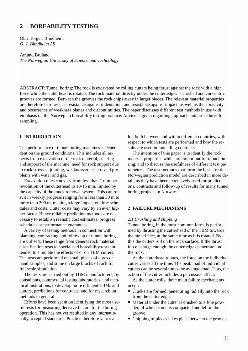
As the cutter rolls, three main failure mechanismsoccur:• Cracks are formed, penetrating radially into the rock
from the cutter edge.• Material under the cutter is crushed to a fine pow-
der, of which some is compacted and left in the groove.
• Chipping of pieces takes place between the grooves.
2 BOREABILITY TESTING
Olav Torgeir BlindheimO. T. Blindheim AS
Amund BrulandThe Norwegian University of Science and Technology
ABSTRACT: Tunnel boring: The rock is excavated by rolling cutters being thrust against the rock with a highforce while the cutterhead is rotated. The rock material directly under the cutter edges is crushed and concentricgrooves are formed. Between the grooves the rock chips away in larger pieces. The relevant material propertiesare therefore hardness, as resistance against indentation, and resistance against impact, as well as the abrasivityand occurrence of weakness planes and discontinuities. The paper discusses different test methods in use withemphasis on the Norwegian boreability testing practice. Advice is given regarding approach and procedures forsampling.
22
Fig. 1. Failure mechanisms under the cutter edge.
The chipping between the grooves does not necessa-rily take place for each pass of the cutter. Dependingon the rock, the thrust per cutter and the cutter spacing,it may take several cutterhead revolutions before theridge between the grooves chips away. Local weaknes-ses in the rock mass will influence the cutting, by allo-wing easier cracking or chipping, or by increasing thesize of the pieces that break loose.
High speed films, performed by Colorado School ofMines of full scale linear disc cutting, show the repea-ted chipping in front and to the side of the cutter edge,and that part of the rock material is being crushed un-der the cutter edge and “blasted” out to the side of theedge. The chipping of larger pieces is obviously amore efficient failure mechanism than the crushingthat takes place under the edge. Both are inherentlypart of the process.
It has been discussed whether the chipping takesplace as a tensile or shear failure. The crack formationtakes place radially from the cutter edge, into the rockor to the next groove, parallel to the high compressivestresses from the cutter edge. The high speed filmsshow that the chips “pop up” from the rock surface be-fore they are pushed sideways. There are obvious simi-larities to the formation of radial cracks from blast ho-les or cracking along high compressive stress trajecto-ries in general. On chips of fine grained rocks it is sometimes possible to observe the characteristic “feat-her” pattern on the surface clearly indicating a tensiletype of failure. The highly dynamic effect must be re-membered, the cutter is actually exerting a series ofimpacts to the rock surface.
2.2 Observations at the tunnel faceWhen a cutterhead is retracted for inspection andchange of cutters, the rock at the tunnel face can beobserved. The concentric grooves with rock powderare easily recognised, and the ridges between the grooves appear with clean surfaces, protruding or almost flat depending on the efficiency of the cutting.
Except for the size and geometry, the similarity tothe bottom of a percussive hole is striking. Both havegrooves after the edge of the bit or cutter and chippedsurfaces in between.
The effect of weakness planes or discontinuities onthe cutting can also be observed, as pieces of rock mayhave been broken out ahead of the general face surface.
3 IMPORTANT PARAMETERS
3.1 StrengthIdeally, an oriented dynamic tensile strength testshould express the properties decisive for crack forma-tion and chipping. As a substitute, the normal classifi-cation tests such as Uniaxial Compressive Strength(UCS) or Point Load Strength Index (IS) are some-times used. UCS may show a correlation to net pene-tration rate for some rock types or within a rock type.However, experience has shown that UCS for manyrock types provides no or poor correlation to net pene-tration rates. Caution should therefore be taken not torely on this parameter alone for boreability estimates.
The Point Load Strength Index IS, which expressesthe strength against indirect tensile failure, shows rea-sonable good correlation to net penetration rates forsome rock types. The correlation will however varyfrom one rock type to another.
In conclusion, these parameters should not be usedas boreability parameters alone. They can however beuseful as supporting parameters for the purpose of ge-neral classification and to allow tentative comparisons.
3.2 Toughness Toughness, or ability to sustain deformation, should inprinciple be a more directly useful parameter. Severaltests are available and are in different ways expressingthe resistance against impact.
One is the Atlas Copco Robbins’ toughness test,performed by a Charpy swing hammer on a piece ofcore. Another is the Protodyakonov's fall hammer testwhich is performed on a sample of crushed rock aggre-gate. This test has been shown to have a correlation tothe Specific Energy for rock breaking.
A similar impact test on crushed aggregate is inclu-ded in the Norwegian set of tests. It was originally de-veloped as a Swedish test for road aggregate. It is de-scribed in more detail in the next section. Also this testmust be expected to reasonably express the SpecificEnergy for rock breaking by impact.
23
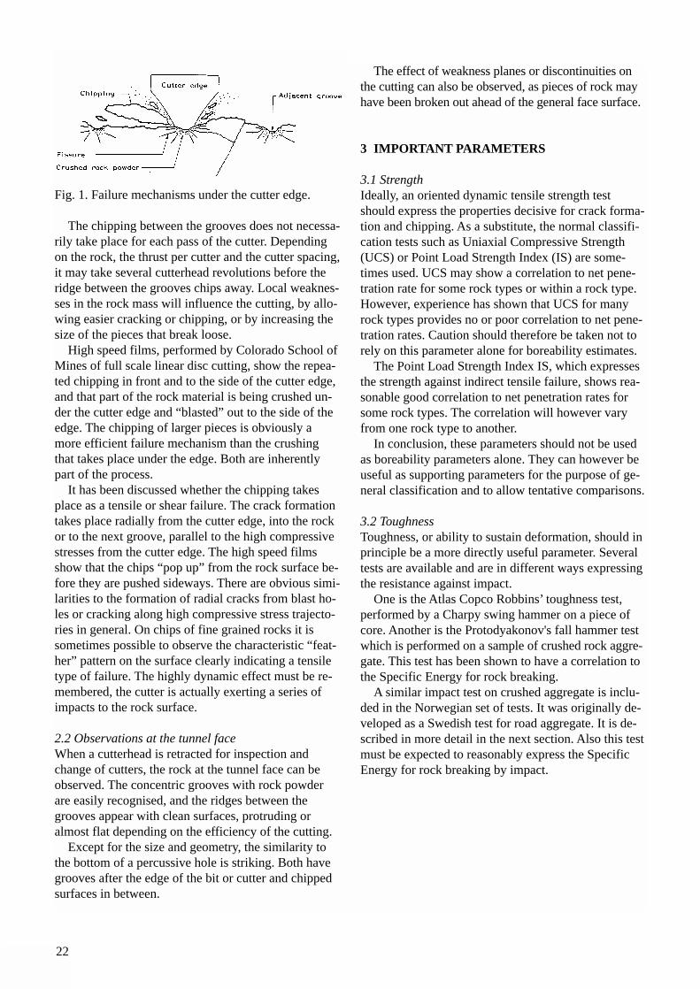
Fig. 2 The impact test to determine the brittleness value.
3.3 HardnessHardness has several definitions, but in this contextthe ability to resist cutting, indentation and/or abrasionmay apply. Several tests express the different aspectsof hardness. Surface indenting tests such as Brinelland Rockwell are not practical for use on rock sam-ples. Vickers' tests have been used to indicate a com-bined rock material hardness based on the hardness ofeach mineral.
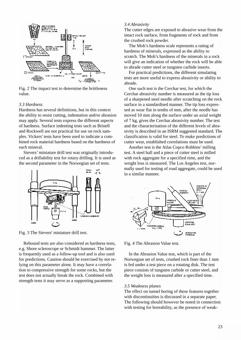
Sievers’ miniature drill test was originally introdu-ced as a drillability test for rotary drilling. It is used asthe second parameter in the Norwegian set of tests.
Fig. 3 The Sievers' miniature drill test.
Rebound tests are also considered as hardness tests,e.g. Shore scleroscope or Schmidt hammer. The latteris frequently used as a follow-up tool and is also usedfor predictions. Caution should be exercised by not re-lying on this parameter alone. It may have a correla-tion to compressive strength for some rocks, but thetest does not actually break the rock. Combined withstrength tests it may serve as a supporting parameter.
3.4 AbrasivityThe cutter edges are exposed to abrasive wear from theintact rock surface, from fragments of rock and fromthe crushed rock powder.
The Moh’s hardness scale represents a rating ofhardness of minerals, expressed as the ability toscratch. The Moh’s hardness of the minerals in a rockwill give an indication of whether the rock will be ableto abrade cutter steel or tungsten carbide inserts.
For practical predictions, the different simulatingtests are more useful to express abrasivity or ability to abrade.
One such test is the Cerchar test, for which theCerchar abrasivity number is measured as the tip lossof a sharpened steel needle after scratching on the rocksurface in a standardised manner. The tip loss expres-sed as wear flat in tenths of mm, after the needle hasmoved 10 mm along the surface under an axial weightof 7 kg, gives the Cerchar abrasivity number. The testand the characterisation of the different levels of abra-sivity is described in an ISRM suggested standard. Theclassification is valid for steel. To make predictions ofcutter wear, established correlations must be used.
Another test is the Atlas Copco Robbins’ millingtest. A steel ball and a piece of cutter steel is milledwith rock aggregate for a specified time, and theweight loss is measured. The Los Angeles test, nor-mally used for testing of road aggregate, could be usedin a similar manner.
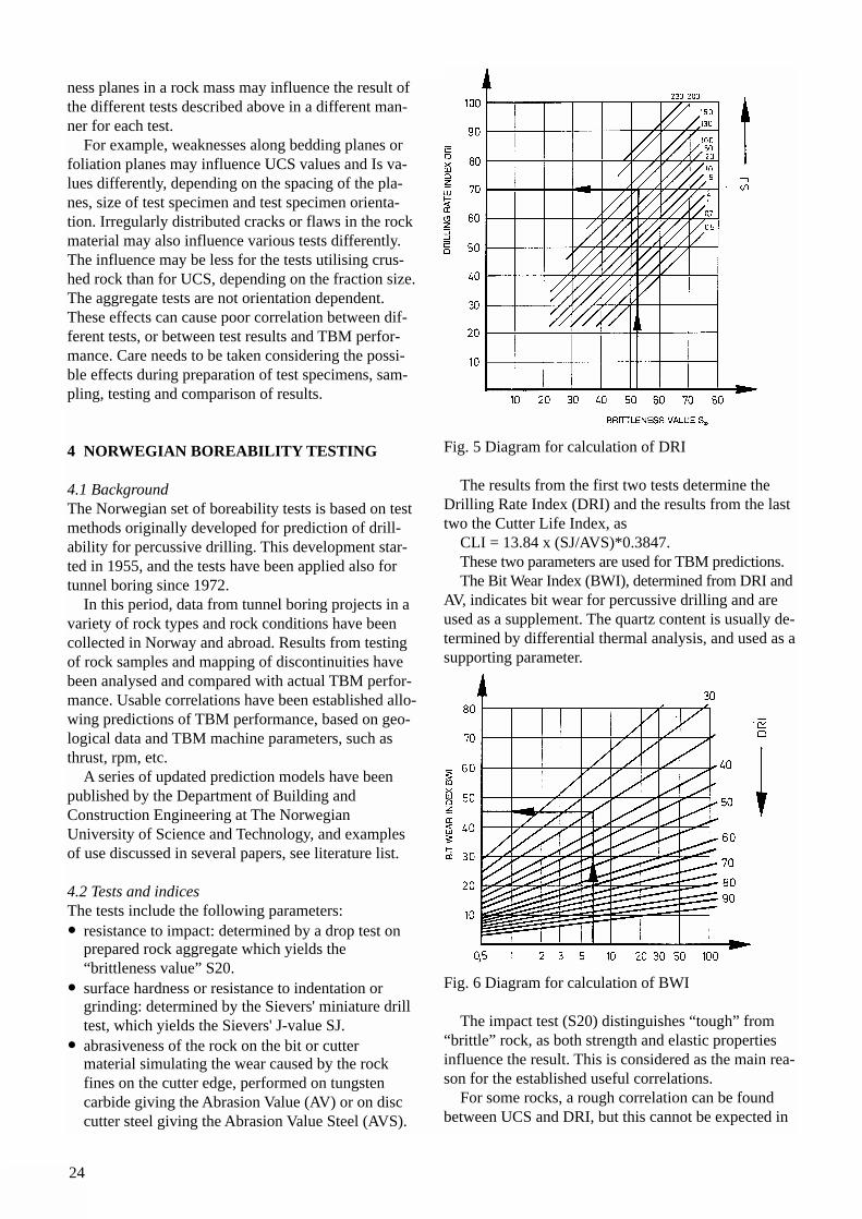
Fig. 4 The Abrasion Value test.
In the Abrasion Value test, which is part of theNorwegian set of tests, crushed rock finer than 1 mmis fed under a test piece on a rotating disk. The test piece consists of tungsten carbide or cutter steel, andthe weight loss is measured after a specified time.
3.5 Weakness planesThe effect on tunnel boring of these features togetherwith discontinuities is discussed in a separate paper.The following should however be noted in connectionwith testing for boreability, as the presence of weak-
24
ness planes in a rock mass may influence the result ofthe different tests described above in a different man-ner for each test.
For example, weaknesses along bedding planes orfoliation planes may influence UCS values and Is va-lues differently, depending on the spacing of the pla-nes, size of test specimen and test specimen orienta-tion. Irregularly distributed cracks or flaws in the rockmaterial may also influence various tests differently.The influence may be less for the tests utilising crus-hed rock than for UCS, depending on the fraction size.The aggregate tests are not orientation dependent.These effects can cause poor correlation between dif-ferent tests, or between test results and TBM perfor-mance. Care needs to be taken considering the possi-ble effects during preparation of test specimens, sam-pling, testing and comparison of results.
4 NORWEGIAN BOREABILITY TESTING
4.1 BackgroundThe Norwegian set of boreability tests is based on testmethods originally developed for prediction of drill-ability for percussive drilling. This development star-ted in 1955, and the tests have been applied also fortunnel boring since 1972.
In this period, data from tunnel boring projects in avariety of rock types and rock conditions have beencollected in Norway and abroad. Results from testingof rock samples and mapping of discontinuities havebeen analysed and compared with actual TBM perfor-mance. Usable correlations have been established allo-wing predictions of TBM performance, based on geo-logical data and TBM machine parameters, such asthrust, rpm, etc.
A series of updated prediction models have been published by the Department of Building andConstruction Engineering at The NorwegianUniversity of Science and Technology, and examplesof use discussed in several papers, see literature list.
4.2 Tests and indicesThe tests include the following parameters:• resistance to impact: determined by a drop test on
prepared rock aggregate which yields the “brittleness value” S20.
• surface hardness or resistance to indentation or grinding: determined by the Sievers' miniature drill test, which yields the Sievers' J-value SJ.
• abrasiveness of the rock on the bit or cutter material simulating the wear caused by the rock fines on the cutter edge, performed on tungsten carbide giving the Abrasion Value (AV) or on disc cutter steel giving the Abrasion Value Steel (AVS).
Fig. 5 Diagram for calculation of DRI
The results from the first two tests determine theDrilling Rate Index (DRI) and the results from the lasttwo the Cutter Life Index, as
CLI = 13.84 x (SJ/AVS)*0.3847. These two parameters are used for TBM predictions. The Bit Wear Index (BWI), determined from DRI and
AV, indicates bit wear for percussive drilling and areused as a supplement. The quartz content is usually de-termined by differential thermal analysis, and used as asupporting parameter.
Fig. 6 Diagram for calculation of BWI
The impact test (S20) distinguishes “tough” from“brittle” rock, as both strength and elastic propertiesinfluence the result. This is considered as the main rea-son for the established useful correlations.
For some rocks, a rough correlation can be foundbetween UCS and DRI, but this cannot be expected in
25
general. For example, two rocks with the same UCSvalues may have different toughness due to differentelastic properties, thus having different DRI valuesand also different TBM performance.
A modified version of the impact test has been de-veloped, in order to make it possible to perform sim-plified tests on smaller samples.
A rough correlation can be found between Cercharvalues and the Cutter Life Index (CLI), but this mustonly be used for comparison purpose, not as a replace-ment for direct testing.
4.3 Drillability catalogueA catalogue is available for the drillability tests perfor-med at the Department of Geology and MineralResources Engineering, Norwegian University ofScience and Technology, listing results for practicallyall the tests performed since the start of such testing.The last revision from 1990 contains results from ap-proximately 1,300 rock samples.
The results are listed according to rock types, deter-mined mostly by petrographic visual inspection, nor-mally supported by differential thermal analysis fordetermination of quartz content, and sometimes by X-ray diffraction for other minerals.
The catalogue contains descriptions of the test met-hods and diagrams for calculation of the different indi-ces. A characterisation of the DRI and BWI values,from “extremely low” to “extremely high”, conside-ring Norwegian rock types, and distribution histo-grams are included. Relations between some of the pa-rameters are also shown.
The catalogue allows comparisons between previ-ously experienced results, and illustrates the often lar-ge variations in mechanical properties that may occurwithin one rock type. It is emphasised that the catalo-gue must be used with care when drillability or borea-bility of specific rocks is evaluated. The catalogue can-not substitute laboratory testing of samples from theactual project.
4.4 SamplingSampling of rock for boreability testing, should alwaysbe based on geological mapping, supported as necessa-ry by core drilling. The number of samples must be de-termined by consideration of the occurring number ofrock types and the variation in properties for eachtype.
In order to achieve representative samples, careshould be taken to:• consider petrographic variations, as some darker
rocks contain minerals making them tougher.• consider grain size, as fine grained rocks frequently
are stronger than coarse grained rock of the same type.
• avoid weathered samples, unless there is assurance that weathered rock is present at tunnel level, and therefore should be included. Always consider the possibility of the effect of weathering on test results even if samples appear “fresh”.
• include not only “typical” samples, thought to be re-presentative for average conditions, but also samplesof “extreme” varieties, as they may have a signifi-cant impact on the TBM performance, thus determi-ning the feasibility of boring with a specific TBM.In case the rock structure or texture shows large
variations over short distances, samples can be takenfrom each variety or composed by adding togetherhand or core pieces in a representative mixture.
Each sample should consist of blocks, or pieces ofcores, to give a total of minimum 10 kg, normally 20kg. Core samples must be larger than 32 mm, but pre-ferably larger than 50 mm since crushed aggregateproduced from cores will contain some pieces withpartly smooth core surface. This influences the test re-sults, and introduces the need for corrections.
The sample should be accompanied by informationabout project name, location and orientation of sam-ple, date and purpose of testing.
5 OTHER TEST METHODS
5.1 Indentation testsIndentation tests in a larger scale than the surface hard-ness tests have been developed and used in many vari-ations. These range from indentation of buttons to seg-ments of discs. The purpose is to simulate the effect ofthe tungsten carbide inserts utilised on percussive androtary drill bits, conical roller discs or disc cutters, in-cluding variations in tool edge shape. Atlas Copcouses a “Stamp Test” by indentation of a spherical but-ton for rock drillability classifications.
For testing with segments of disc cutters, the loa-ding velocity is usually so low that there is no impacteffect, thus only the static strength has an effect. Thetest can simulate both the crushing under the tool edgeand the chipping to the side. More realistic values areachieved if the indentation is repeated with a spacing,thus including the chipping between the grooves.
Normally the force/penetration relationship is recor-ded and the force level at first penetration and chip-ping is considered as indicative of critical thrust.
It is important that the sample is confined by highstrength casting in a conical steel cylinder or box.Otherwise the samples may split for a low force.Depending on the size of the tool, the test can be de-manding with respect to preparation work and testingequipment. It is therefore more useful for comparativetesting, rather than for routine boreability testing.
26
5.2 Linear and rotational testsThe Excavation Engineering and Earth MechanicInstitute at Colorado School of Mines (CSM), develo-ped the full scale linear cutting tests as a tool for esta-blishing boreability prediction formulas. It has alsobeen used for predictions of TBM performance, by tes-ting with different types of cutters and thrust levels.
Typical block size needed for testing is 1 m x 1 m x0.5 m, although samples down to 0.6 m x 0.6 m x 0.3m can be used. Tests have been performed on cores of150 mm diameter, cut to prisms and cast side by sideto provide a sample of sufficient size.
A 1.8 m diameter rotation cutting rig, allowing si-mulation of cutting in circular grooves has also beendeveloped by CSM. This test needs four rock blocks ofapproximately 1 m x 1 m x 0.8 m.
Such tests give results useful for predictions of netpenetration in massive rock. Due to the need of largerock samples the use will be limited to special cases.
Other research institutions, and manufacturers, havealso utilised linear or rotational cutting for researchand development objectives or for specific project pre-diction testing.
6 CONCLUSION
6.1 Use of boreability testsTunnel boring machines have become more powerfulover the years, both with respect to thrust and torquecapacity. Still the performance is strongly dependenton the rock boreability.
Therefore boreability testing has a useful purposeon the planning stage for comparisons between Drill &Blast tunnelling and tunnel boring, on the tenderingstage and during the follow-up for contractual purposeor experience analysis.
When boreability test results and indices are inclu-ded in tender documents, the purpose has to be clearlystated, and the representativeness should be addressed,especially if the number of samples is low.
Sometimes boreability test results and indices havebeen included in the tender documents, and used as aspecified basis for quantified boreability classes. Theextent of these classes are then logged during con-struction and payment adjusted accordingly. This ap-proach has been useful in cases where risk sharing isan integral part of a purchase agreement or a construc-tion contract.
It must however be realised that the performance ofa TBM is also very dependent on the amount of weak-ness planes and discontinuities in the rock mass, andupon how it is operated. Too elaborate contractual re-gulations according to rock boreability alone can the-
refore give unforeseeable effects, so caution must beobserved.
Today, contractors experienced in tunnel boring willbe able to assess the risk of performance in most rocktypes, provided that relevant results from thorough in-vestigations and testing are presented for their evalua-tion. For difficult conditions, a boreability evaluationreport can be a useful supplement to the test results.
6.2 DevelopmentBecause of the large variation in boreability betweenand within different rock types, as well as the domi-nant effect of weakness planes and discontinuities onTBM performance, it is important that boreability testsare simple and inexpensive, to allow the tests to beperformed in large numbers.
Research is ongoing for the Norwegian set of tests,in order to make it possible to perform impact tests onsmaller samples. Such tests will give a first impres-sion, before a test programme on full size samples canbe performed. The small sample testing will also easesampling for follow up purposes.
It must be expected that there will be an increasedneed to compare results between different test methods. Such comparisons will be useful for the exchange of experience, but one has to be realisticabout the general validity of any correlation establis-hed only for a few rock types.
In total, boreability testing will continue to form aninherent part of the preparation for tunnel boring andthe follow up of TBM performance, of special impor-tance for hard and abrasive rocks.
LITERATURE
Blindheim, O. T. (1979): "Boreability predictions fortunnelling". Dr. ing. Thesis, Department of GeologicalEngineering. The Norwegian Institute of Technology,Trondheim, (In Norwegian), 406 p
Blindheim, O. T. (1979): "Failure mechanisms underdisc cutters". Rock Mechanics Conference, Oslo, (InNorwegian), 12 p
Blindheim, O. T. & Boniface, A., (1989): "Boreabilityassessments for major tunnelling projects", SANCOTSeminar, 6 p
Blindheim, O. T., Boniface, A. & Richards, J. A.(1990): "Boreability assessments for the LesothoHighlands Water Project" Int. Soc. Rock Mechanics,Swaziland Symposium, 10 p(Short version in Tunnels & Tunnelling June 1991)
27
Bruland, A. & Dahlø, T. (1995): "Tunnelling perfor-mance estimation based on drillability testing". Proc.ISRM 8th Conf. On Rock Mechanics, Tokyo, pp 123-126
Bruland, A., Eriksen, S., Johannessen, O. & Myran, A.(1990): "Drillability - Drilling Rate Index Catalogue.Project Report 13-90" The Division of ConstructionEngineering, The Department of Geology, Universityof Trondheim, The Norwegian Institute of Technology,Trondheim, 177 p
Bruland, A., Johannessen, O., Lima, J. & Sandberg, B.(1994): "Hard Rock Tunnel Boring. Project Report 1-94". The Division of Construction Engineering,University of Trondheim, The Norwegian Institute ofTechnology, Trondheim, 164 p
Lislerud, A. (1988): "Hard Rock Tunnel Boring:Prognosis and Costs". Tunnelling and UndergroundSpace Technology, Vol. 3, No. 1, pp 9-17.
McKelvey, J. G., Schultz, E. A., Helin, T. A. B. &Blindheim, O. T. (1996): "Geotechnical Analysis inSouth Africa" (Inanda-Wiggins Aqueduct Phase 2,Construction of Emolweni and Clermont Tunnels,Predicted and Actual TBM Performance), WorldTunnelling, November, pp 377-390
Movinkel, T. & Johannessen, O. (1986): "Geologicalparameters for hard rock tunnel boring" Tunnels &Tunnelling, April, 4 p
Ozdemir, L., Miller, R. & Wang, F.-D. (1977):"Mechanical Tunnel Boring, Prediction and Machinedesign". Excavation Engineering and Earth MechanicsInstitute, Colorado School of Mines, 313 p
Selmer-Olsen, R., & Blindheim, O. T. (1970): "On theDrillability of Rocks by Percussive Drilling". Proc.ISRM 2nd Conf. on Rock Mechanics, Belgrade, 6 p

28
29
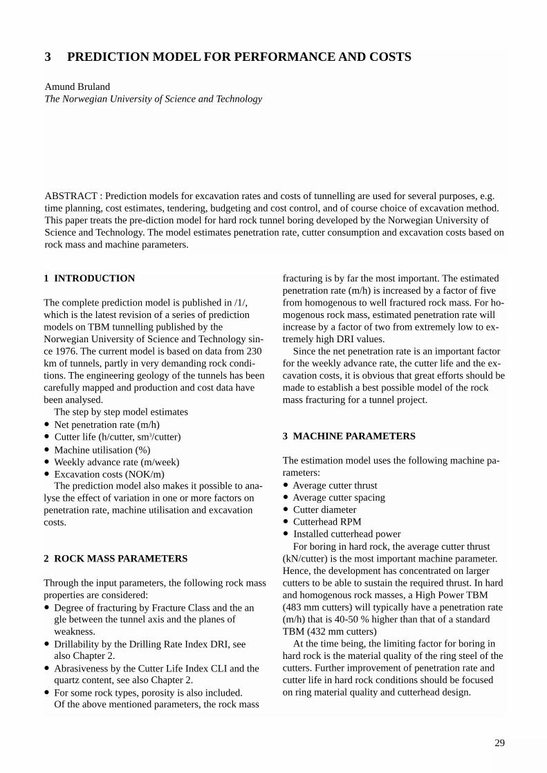
1 INTRODUCTION
The complete prediction model is published in /1/,which is the latest revision of a series of predictionmodels on TBM tunnelling published by theNorwegian University of Science and Technology sin-ce 1976. The current model is based on data from 230km of tunnels, partly in very demanding rock condi-tions. The engineering geology of the tunnels has beencarefully mapped and production and cost data havebeen analysed.
The step by step model estimates• Net penetration rate (m/h)• Cutter life (h/cutter, sm3/cutter)• Machine utilisation (%)• Weekly advance rate (m/week)• Excavation costs (NOK/m)
The prediction model also makes it possible to ana-lyse the effect of variation in one or more factors onpenetration rate, machine utilisation and excavationcosts.
2 ROCK MASS PARAMETERS
Through the input parameters, the following rock massproperties are considered:• Degree of fracturing by Fracture Class and the an
gle between the tunnel axis and the planes of weakness.
• Drillability by the Drilling Rate Index DRI, see also Chapter 2.
• Abrasiveness by the Cutter Life Index CLI and the quartz content, see also Chapter 2.
• For some rock types, porosity is also included.Of the above mentioned parameters, the rock mass
fracturing is by far the most important. The estimatedpenetration rate (m/h) is increased by a factor of fivefrom homogenous to well fractured rock mass. For ho-mogenous rock mass, estimated penetration rate willincrease by a factor of two from extremely low to ex-tremely high DRI values.
Since the net penetration rate is an important factorfor the weekly advance rate, the cutter life and the ex-cavation costs, it is obvious that great efforts should bemade to establish a best possible model of the rockmass fracturing for a tunnel project.
3 MACHINE PARAMETERS
The estimation model uses the following machine pa-rameters:• Average cutter thrust• Average cutter spacing• Cutter diameter• Cutterhead RPM• Installed cutterhead power
For boring in hard rock, the average cutter thrust(kN/cutter) is the most important machine parameter.Hence, the development has concentrated on largercutters to be able to sustain the required thrust. In hardand homogenous rock masses, a High Power TBM(483 mm cutters) will typically have a penetration rate(m/h) that is 40-50 % higher than that of a standardTBM (432 mm cutters)
At the time being, the limiting factor for boring inhard rock is the material quality of the ring steel of thecutters. Further improvement of penetration rate andcutter life in hard rock conditions should be focusedon ring material quality and cutterhead design.
3 PREDICTION MODEL FOR PERFORMANCE AND COSTS
Amund BrulandThe Norwegian University of Science and Technology
ABSTRACT : Prediction models for excavation rates and costs of tunnelling are used for several purposes, e.g.time planning, cost estimates, tendering, budgeting and cost control, and of course choice of excavation method.This paper treats the pre-diction model for hard rock tunnel boring developed by the Norwegian University ofScience and Technology. The model estimates penetration rate, cutter consumption and excavation costs based onrock mass and machine parameters.
30
4 NET PENETRATION RATE
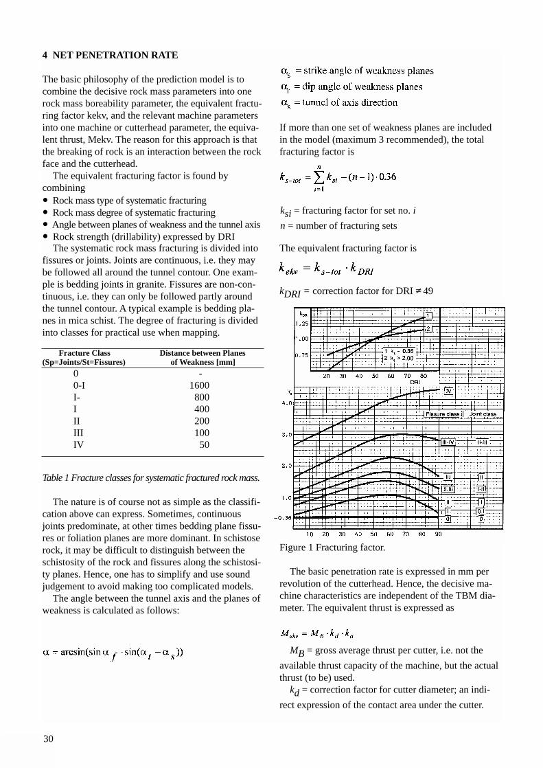
The basic philosophy of the prediction model is tocombine the decisive rock mass parameters into onerock mass boreability parameter, the equivalent fractu-ring factor kekv, and the relevant machine parametersinto one machine or cutterhead parameter, the equiva-lent thrust, Mekv. The reason for this approach is thatthe breaking of rock is an interaction between the rockface and the cutterhead.
The equivalent fracturing factor is found by combining• Rock mass type of systematic fracturing• Rock mass degree of systematic fracturing• Angle between planes of weakness and the tunnel axis• Rock strength (drillability) expressed by DRI
The systematic rock mass fracturing is divided intofissures or joints. Joints are continuous, i.e. they maybe followed all around the tunnel contour. One exam-ple is bedding joints in granite. Fissures are non-con-tinuous, i.e. they can only be followed partly aroundthe tunnel contour. A typical example is bedding pla-nes in mica schist. The degree of fracturing is dividedinto classes for practical use when mapping.
Fracture Class Distance between Planes(Sp=Joints/St=Fissures) of Weakness [mm]
0 -0-I 1600I- 800I 400II 200III 100IV 50
Table 1 Fracture classes for systematic fractured rock mass.
The nature is of course not as simple as the classifi-cation above can express. Sometimes, continuousjoints predominate, at other times bedding plane fissu-res or foliation planes are more dominant. In schistoserock, it may be difficult to distinguish between theschistosity of the rock and fissures along the schistosi-ty planes. Hence, one has to simplify and use soundjudgement to avoid making too complicated models.
The angle between the tunnel axis and the planes ofweakness is calculated as follows:
If more than one set of weakness planes are includedin the model (maximum 3 recommended), the totalfracturing factor is
The equivalent fracturing factor is
kDRI = correction factor for DRI 49
Figure 1 Fracturing factor.
The basic penetration rate is expressed in mm perrevolution of the cutterhead. Hence, the decisive ma-chine characteristics are independent of the TBM dia-meter. The equivalent thrust is expressed as
MB = gross average thrust per cutter, i.e. not the
available thrust capacity of the machine, but the actualthrust (to be) used.
kd = correction factor for cutter diameter; an indi-
rect expression of the contact area under the cutter.
ksi = fracturing factor for set no. i
n = number of fracturing sets
31
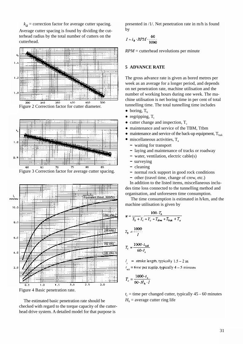
ka = correction factor for average cutter spacing.
Average cutter spacing is found by dividing the cut-terhead radius by the total number of cutters on thecutterhead.
Figure 2 Correction factor for cutter diameter.
Figure 3 Correction factor for average cutter spacing.
Figure 4 Basic penetration rate.
The estimated basic penetration rate should be checked with regard to the torque capacity of the cutter-head drive system. A detailed model for that purpose is
presented in /1/. Net penetration rate in m/h is foundby
RPM = cutterhead revolutions per minute
5 ADVANCE RATE
The gross advance rate is given as bored metres perweek as an average for a longer period, and dependson net penetration rate, machine utilisation and thenumber of working hours during one week. The ma-chine utilisation is net boring time in per cent of totaltunnelling time. The total tunnelling time includes• boring, Tb
• regripping, Tt
• cutter change and inspection, Tc
• maintenance and service of the TBM, Ttbm• maintenance and service of the back-up equipment, Tbak
• miscellaneous activities, Ta
- waiting for transport- laying and maintenance of tracks or roadway- water, ventilation, electric cable(s)- surveying- cleaning- normal rock support in good rock conditions- other (travel time, change of crew, etc.)In addition to the listed items, miscellaneous inclu-
des time loss connected to the tunnelling method andorganisation, and unforeseen time consumption.
The time consumption is estimated in h/km, and themachine utilisation is given by
tc = time per changed cutter, typically 45 - 60 minutesHh = average cutter ring life
32
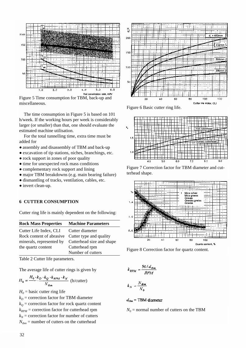
Figure 5 Time consumption for TBM, back-up andmiscellaneous.
The time consumption in Figure 5 is based on 101h/week. If the working hours per week is considerablylarger (or smaller) than that, one should evaluate theestimated machine utilisation.
For the total tunnelling time, extra time must be added for• assembly and disassembly of TBM and back-up• excavation of tip stations, niches, branchings, etc.• rock support in zones of poor quality• time for unexpected rock mass conditions• complementary rock support and lining• major TBM breakdowns (e.g. main bearing failure)• dismantling of tracks, ventilation, cables, etc.• invert clean-up.
6 CUTTER CONSUMPTION
Cutter ring life is mainly dependent on the following:
Rock Mass Properties Machine Parameters
Cutter Life Index, CLI Cutter diameterRock content of abrasive Cutter type and qualityminerals, represented by Cutterhead size and shapethe quartz content Cutterhead rpm
Number of cuttersTable 2 Cutter life parameters.
The average life of cutter rings is given by
(h/cutter)
H0 = basic cutter ring lifekD = correction factor for TBM diameterkQ = correction factor for rock quartz contentkRPM = correction factor for cutterhead rpmkN = correction factor for number of cuttersNtbm = number of cutters on the cutterhead
Figure 6 Basic cutter ring life.
Figure 7 Correction factor for TBM diameter and cut-terhead shape.
Figure 8 Correction factor for quartz content.
N0 = normal number of cutters on the TBM
33
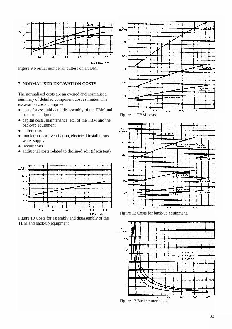
Figure 9 Normal number of cutters on a TBM.
7 NORMALISED EXCAVATION COSTS
The normalised costs are an evened and normalisedsummary of detailed component cost estimates. Theexcavation costs comprise• costs for assembly and disassembly of the TBM and
back-up equipment• capital costs, maintenance, etc. of the TBM and the
back-up equipment• cutter costs• muck transport, ventilation, electrical installations,
water supply• labour costs• additional costs related to declined adit (if existent)
Figure 10 Costs for assembly and disassembly of theTBM and back-up equipment
Figure 11 TBM costs.
Figure 12 Costs for back-up equipment.
Figure 13 Basic cutter costs.
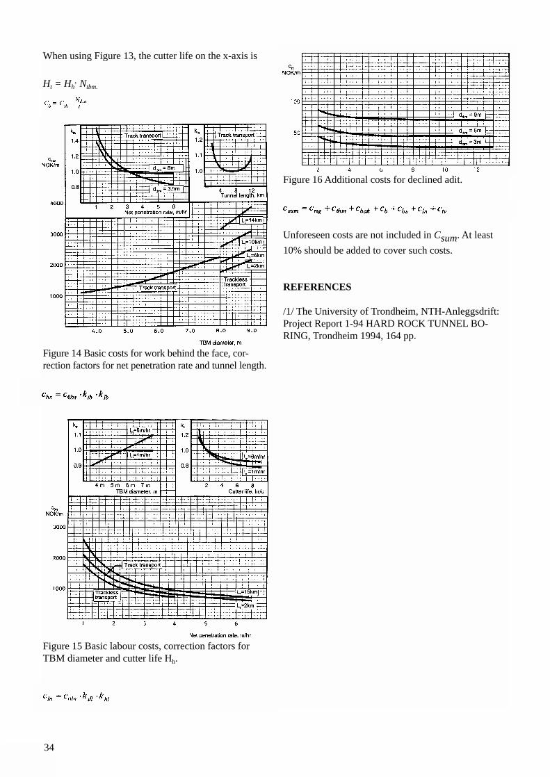
34
When using Figure 13, the cutter life on the x-axis is
Ht = Hh. Ntbm.
Figure 14 Basic costs for work behind the face, cor-rection factors for net penetration rate and tunnel length.
Figure 15 Basic labour costs, correction factors forTBM diameter and cutter life Hh.
Figure 16 Additional costs for declined adit.
Unforeseen costs are not included in Csum. At least
10% should be added to cover such costs.
REFERENCES
/1/ The University of Trondheim, NTH-Anleggsdrift:Project Report 1-94 HARD ROCK TUNNEL BO-RING, Trondheim 1994, 164 pp.
35
1 BRIEF HISTORY OF TUNNEL BORINGMACHINES
In 1851 an American Engineer Charles Wilson develo-ped a tunnelling machine which is generally conside-red as the first successful continuous borer for rock.However, problems with cutter technology combinedwith other mechanical difficulties made it not competi-tive with the rapidly developing techniques of Drill &Blast tunnelling. Though Mr. Wilson's concept ofusing disc cutters turned out to be correct, it took al-most a century before his ideas were developed andput into use.
Other famous undertakings include the compressedair driven TBM developed by Colonel Beaumont in1881 for an exploratory tunnel under the EnglishChannel. This machine was fitted with a massive headwith bits designed to carve concentric rings in thechalk. This 2.1 m diameter machine may be conside-red as rather primitive today, but it bored more than1.8 km with daily advance rate of 24.5 m! In 1882 allwork on the English side was cancelled due to political pressure.
Practically no serious attempts were made until1952 when James S. Robbins designed a TBM to beused for four tunnels at Oahe Dam in South Dakota.This unit was 7.85 m in diameter and with a cutterhead consisting to two counter rotating heads - an in-ner and an outer section. The cutterhead was fittedwith fixed carbide drag bits radially arranged, and pa-rallel rows of freely rolling disc cutters, which wereprotruding slightly less than the carbide drag bits. It isof interest to note that this machine was powered by 2-150 kW motors and had a total weight of approxi-
mately 114 t. While the machine was not designed foruse in hard rock, it successfully bored through softshale advancing up to a world record of 45 m/day. 356drag bits and four disc cutters were reportedly replacedduring the four tunnel drives.
The first successful hard rock TBM was built in1956 for the Foundation Company of Canada for useon the 4.5 km long Humber Sewer Project in Toronto,Canada. This 3.28 m dia. Robbins TBM (Model 131-107) was contracted for boring through sandstone, sha-le and crystalline limestone - UCS reported from 5-186 MPa. The TBM was designed and equipped withdrag bits as well as cutters to cut the rock. During theinitial boring period, it was decided to try removingthe high wearing drag bits, leaving only disc cutters onthe single rotational head. This experiment turned outto be a success, and it became the accepted concept forusing disc cutters exclusively in hard rock conditions.
Since the mid 1950's the development of TBMs hasprogressed in two directions:• Enable machines to bore tunnels in massive, hard
and abrasive rock.• Enable machines to bore tunnels in stable, compe-
tent rock as well as in ground so unstable that the tunnel has to be lined concurrently with the excavation.
This paper deals with the hard rock open type TBMs.Detail follow-up of more than 300 km hard rock
TBM tunnels by Norwegian contractors, consultantsand universities have played a major role in the under-standing and prediction of the rock cutting process andthe developments in the TBM technology.
4 DEVELOPMENT OF TBM TECHNOLOGYFOR HARD ROCK CONDITIONS
Odd G. AskilsrudAtlas Copco Robbins Inc., Seattle, USA
ABSTRACT: This paper gives a brief history and development of hard rock Tunnel Boring Machines (TBMs).Since the early 1970's, some sixty tunnel projects have been completed by open, hard rock TBMs in Scandinavia,and all but ten of these projects have taken place in Norway. Atlas Copco Robbins TBMs have played a majorrole in this development and have been used on approximately 85 percent of the 300 km driven. This paper provi-des basic description and operating principles of the modern open, hard rock Robbins Main Beam and Main Kellytype machines, and reviews the current state of the art main bearing arrangement and cutters. A listing of impor-tant geological, tunnel design and machine factors to be reviewed during a TBM project study is also included.
36
2 HARD ROCK - DEFINITION
A definition of "hard rock" can easily lead to contro-versy. Common definitions include:• Unconfined compressive Strength (UCS) exceeding
approximately 50-100 MPa.• A mineral matter that cannot economically be excava-
ted by a road header.• Something hard, consolidated and/or load bearing,
which, where necessary, has to be removed by blasting.• A rock sample that requires more than one blow by a
geology hammer to split.• Metamorphic and igneous rocks (i.e. not
sedimentary rock).For the purpose of this paper hard (strong) rock is defi-ned according to ISRM (1980) with UCS exceeding50-100 MPa.
2.1 Important factors for hard rock tunnelling systemsA. Geological factors:• Rock mass strength and elastic properties• Rock types and rock abrasiveness• Degree and type of jointing and/or fissuring of
the rock mass• Rock porosity and friability• Dip, strike and direction of drive• Over burden and in situ stress• Faults• Stand up time• Water inflow• Possibility of gas• Ambient rock temperatures
B. Tunnel Design factors and requirements• Alignment • Gradients in the direction of drive• Rock support requirements - bolts, partial or
full ring beams, welded wire mesh, steel straps, shotcrete, in situ concrete, concrete segments or steel liner plates
• Tolerance requirements• Ground pressure limitations• Probing and pre-excavation injection
requirements• Assembly and start-up schemes• Contract schedule including excavation period• Possibility of more than one heading• Power supply• Time schedule• Environmental issues
C Machine design factors - based upon above items A and B• Cutter capacity, diameter, tip width, spacing,
protrusion and cutterhead profile.
• Cutter attachment (cutter housing) type• Cutter changing (front loading and/or backloa-
ding features)• Cutterhead stiffness and stability• Cutterhead rpm• Mucking capacity and systems• Main bearing and seal assembly• Cutterhead drive system. • Power and torque requirements for balanced design• Hydraulic and lube system requirements• Electrical system requirements• Structural integrity• Thrust and torque reaction systems• Rock support installations• Simplicity and ease of operation• Safety of personnel• Interphase with back-up system and ancillary
tunnel equipment• Capital cost, estimated production rates,
cutters and spare parts costs to fit budget and production schedules.Some of the important machine design factors are specifically addressed below:
3 CUTTERS
The hard rock tunnel boring is a form of crushing andchipping of rock with disc cutters applied against therock face with brute force. The cutters will penetrate acertain depth into the rock face for each revolution de-pending upon the machine and cutter characteristicsand the geological factors. TBM rate of penetration(ROP) is typically defined in mm per revolution of thecutterhead.
In the contact area between the cutter tip and therock, the rock is crushed to powder. From this zone,cracks will propagate towards the neighbouring groove(kerf) and rock face will spall in a combination ofchips and fines. The actual cutter indentation determi-nes the depth of the crack formation and it is a functi-on of the force applied to the cutter and the cutter footprint. For each rock type, a minimum thrust will typi-cally be required to indent the rock effectively. If thespacing between the grooves are too large, the stresspattern created may not reach the influence zone cau-sed by adjacent cutters. This will cause inefficient bo-ring and low rate of penetration. On the other hand ifthe spacing is too close or the cutter tip is too blunt,only small chips will form, generally meaning ineffi-cient boring and low overall rate of penetration.
The thrust force, cutter type and cutter spacing aretherefore among the most important factors in theTBM evaluation. These factors will in turn affect thedesign and price of a TBM and play a major role in theoverall project schedule and cost.
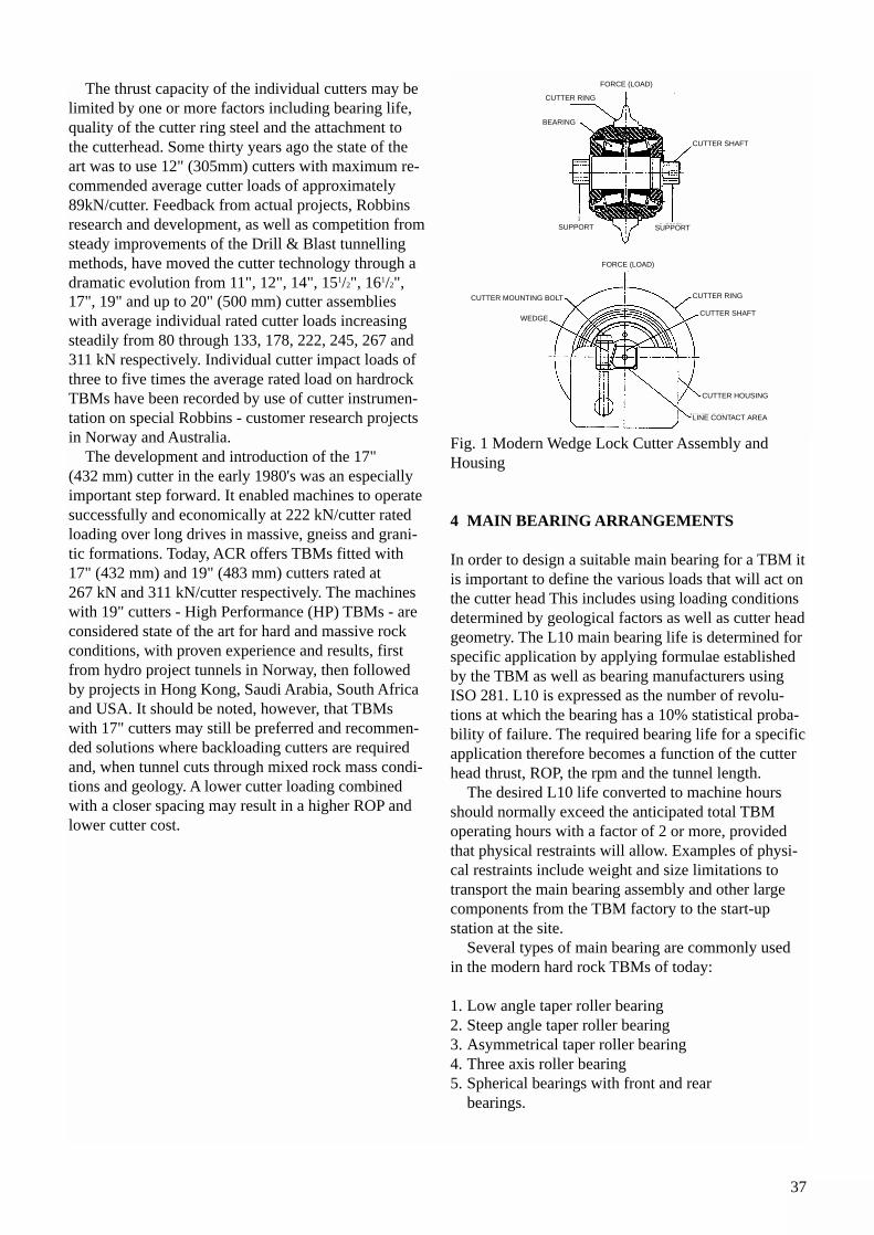
37
The thrust capacity of the individual cutters may belimited by one or more factors including bearing life,quality of the cutter ring steel and the attachment tothe cutterhead. Some thirty years ago the state of theart was to use 12" (305mm) cutters with maximum re-commended average cutter loads of approximately89kN/cutter. Feedback from actual projects, Robbinsresearch and development, as well as competition fromsteady improvements of the Drill & Blast tunnellingmethods, have moved the cutter technology through adramatic evolution from 11", 12", 14", 151/2", 161/2",17", 19" and up to 20" (500 mm) cutter assemblieswith average individual rated cutter loads increasingsteadily from 80 through 133, 178, 222, 245, 267 and311 kN respectively. Individual cutter impact loads ofthree to five times the average rated load on hardrockTBMs have been recorded by use of cutter instrumen-tation on special Robbins - customer research projectsin Norway and Australia.
The development and introduction of the 17" (432 mm) cutter in the early 1980's was an especiallyimportant step forward. It enabled machines to operatesuccessfully and economically at 222 kN/cutter ratedloading over long drives in massive, gneiss and grani-tic formations. Today, ACR offers TBMs fitted with17" (432 mm) and 19" (483 mm) cutters rated at 267 kN and 311 kN/cutter respectively. The machineswith 19" cutters - High Performance (HP) TBMs - areconsidered state of the art for hard and massive rockconditions, with proven experience and results, firstfrom hydro project tunnels in Norway, then followedby projects in Hong Kong, Saudi Arabia, South Africaand USA. It should be noted, however, that TBMswith 17" cutters may still be preferred and recommen-ded solutions where backloading cutters are requiredand, when tunnel cuts through mixed rock mass condi-tions and geology. A lower cutter loading combinedwith a closer spacing may result in a higher ROP andlower cutter cost.
Fig. 1 Modern Wedge Lock Cutter Assembly andHousing
4 MAIN BEARING ARRANGEMENTS
In order to design a suitable main bearing for a TBM itis important to define the various loads that will act onthe cutter head This includes using loading conditionsdetermined by geological factors as well as cutter headgeometry. The L10 main bearing life is determined forspecific application by applying formulae establishedby the TBM as well as bearing manufacturers usingISO 281. L10 is expressed as the number of revolu-tions at which the bearing has a 10% statistical proba-bility of failure. The required bearing life for a specificapplication therefore becomes a function of the cutterhead thrust, ROP, the rpm and the tunnel length.
The desired L10 life converted to machine hoursshould normally exceed the anticipated total TBMoperating hours with a factor of 2 or more, providedthat physical restraints will allow. Examples of physi-cal restraints include weight and size limitations totransport the main bearing assembly and other largecomponents from the TBM factory to the start-up station at the site.
Several types of main bearing are commonly usedin the modern hard rock TBMs of today:
1. Low angle taper roller bearing2. Steep angle taper roller bearing3. Asymmetrical taper roller bearing4. Three axis roller bearing5. Spherical bearings with front and rear
bearings.
CUTTER RING
FORCE (LOAD)
CUTTER SHAFT
SUPPORTSUPPORT
FORCE (LOAD)
CUTTER RING
CUTTER SHAFT
CUTTER HOUSING
LINE CONTACT AREA
CUTTER MOUNTING BOLT
WEDGE
BEARING
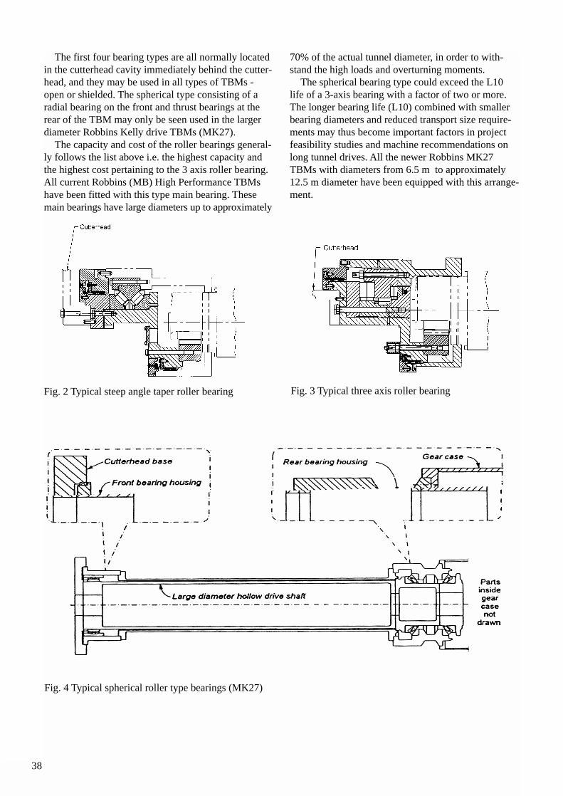
38
The first four bearing types are all normally locatedin the cutterhead cavity immediately behind the cutter-head, and they may be used in all types of TBMs -open or shielded. The spherical type consisting of a radial bearing on the front and thrust bearings at therear of the TBM may only be seen used in the largerdiameter Robbins Kelly drive TBMs (MK27).
The capacity and cost of the roller bearings general-ly follows the list above i.e. the highest capacity andthe highest cost pertaining to the 3 axis roller bearing.All current Robbins (MB) High Performance TBMshave been fitted with this type main bearing. Thesemain bearings have large diameters up to approximately
70% of the actual tunnel diameter, in order to with-stand the high loads and overturning moments.
The spherical bearing type could exceed the L10life of a 3-axis bearing with a factor of two or more.The longer bearing life (L10) combined with smallerbearing diameters and reduced transport size require-ments may thus become important factors in projectfeasibility studies and machine recommendations onlong tunnel drives. All the newer Robbins MK27TBMs with diameters from 6.5 m to approximately12.5 m diameter have been equipped with this arrange-ment.
Fig. 2 Typical steep angle taper roller bearing Fig. 3 Typical three axis roller bearing
Fig. 4 Typical spherical roller type bearings (MK27)
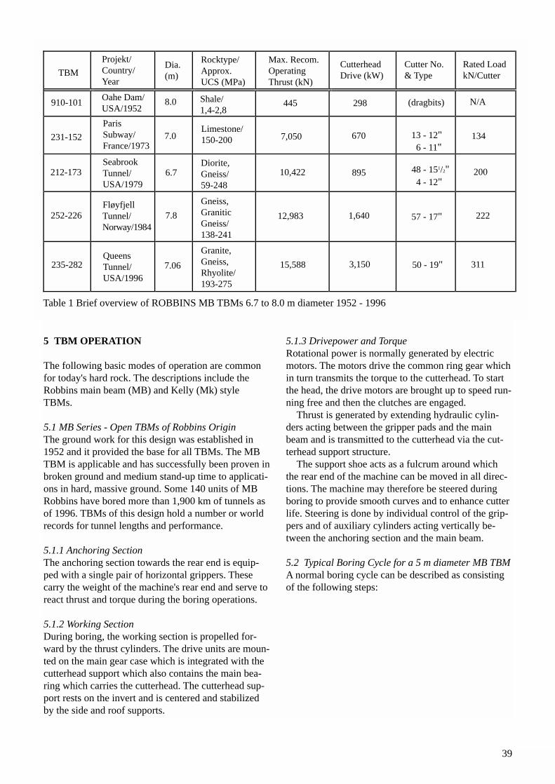
39
5 TBM OPERATION
The following basic modes of operation are commonfor today's hard rock. The descriptions include theRobbins main beam (MB) and Kelly (Mk) styleTBMs.
5.1 MB Series - Open TBMs of Robbins OriginThe ground work for this design was established in1952 and it provided the base for all TBMs. The MBTBM is applicable and has successfully been proven inbroken ground and medium stand-up time to applicati-ons in hard, massive ground. Some 140 units of MBRobbins have bored more than 1,900 km of tunnels asof 1996. TBMs of this design hold a number or worldrecords for tunnel lengths and performance.
5.1.1 Anchoring SectionThe anchoring section towards the rear end is equip-ped with a single pair of horizontal grippers. Thesecarry the weight of the machine's rear end and serve toreact thrust and torque during the boring operations.
5.1.2 Working SectionDuring boring, the working section is propelled for-ward by the thrust cylinders. The drive units are moun-ted on the main gear case which is integrated with thecutterhead support which also contains the main bea-ring which carries the cutterhead. The cutterhead sup-port rests on the invert and is centered and stabilizedby the side and roof supports.
5.1.3 Drivepower and TorqueRotational power is normally generated by electricmotors. The motors drive the common ring gear whichin turn transmits the torque to the cutterhead. To startthe head, the drive motors are brought up to speed run-ning free and then the clutches are engaged.
Thrust is generated by extending hydraulic cylin-ders acting between the gripper pads and the mainbeam and is transmitted to the cutterhead via the cut-terhead support structure.
The support shoe acts as a fulcrum around whichthe rear end of the machine can be moved in all direc-tions. The machine may therefore be steered duringboring to provide smooth curves and to enhance cutterlife. Steering is done by individual control of the grip-pers and of auxiliary cylinders acting vertically be-tween the anchoring section and the main beam.
5.2 Typical Boring Cycle for a 5 m diameter MB TBMA normal boring cycle can be described as consistingof the following steps:
FløyfjellTunnel/Norway/1984
TBM
Projekt/Country/Year
Dia.(m)
Rocktype/Approx.UCS (MPa)
Max. Recom.OperatingThrust (kN)
CutterheadDrive (kW)
Cutter No.& Type
Rated LoadkN/Cutter
910-101
231-152
212-173
252-226
235-282
Oahe Dam/USA/1952
ParisSubway/France/1973
SeabrookTunnel/USA/1979
QueensTunnel/USA/1996
8.0
7.0
6.7
7.8
7.06
Shale/1,4-2,8
Limestone/150-200
Diorite,Gneiss/59-248
Gneiss,GraniticGneiss/138-241
Granite,Gneiss,Rhyolite/193-275
445
7,050
10,422
12,983
15,588
298
670
895
1,640
3,150
(dragbits)
13 - 12"6 - 11"
48 - 151/2"4 - 12"
57 - 17"
50 - 19"
N/A
134
200
222
311
Table 1 Brief overview of ROBBINS MB TBMs 6.7 to 8.0 m diameter 1952 - 1996
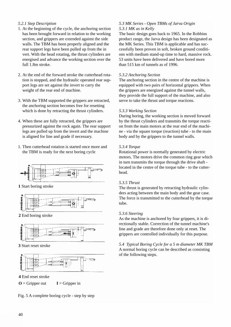
40
5.2.1 Step Description1. At the beginning of the cycle, the anchoring section
has been brought forward in relation to the working section, and grippers are extended against the sidewalls. The TBM has been properly aligned and the rear support legs have been pulled up from the invert. With the head rotating, the thrust cylinders are energised and advance the working section over the full 1.8m stroke.
2. At the end of the forward stroke the cutterhead rota-tion is stopped, and the hydraulic operated rear sup-port legs are set against the invert to carry the weight of the rear end of machine.
3. With the TBM supported the grippers are retracted, the anchoring section becomes free for resetting which is done by retracting the thrust cylinders.
4. When these are fully retracted, the grippers are pressurized against the rock again. The rear support legs are pulled up from the invert and the machine is aligned for line and grade if necessary.
1. Then cutterhead rotation is started once more and the TBM is ready for the next boring cycle
Fig. 5 A complete boring cycle - step by step
5.3 MK Series - Open TBMs of Jarva Origin5.3.1 MK as in KellyThe basic design goes back to 1965. In the Robbinsproduct range, the Jarva design has been designated asthe MK Series. This TBM is applicable and has suc-cessfully been proven in soft, broken ground conditi-ons with medium stand-up time to hard, massive rock.53 units have been delivered and have bored morethan 515 km of tunnels as of 1996.
5.3.2 Anchoring SectionThe anchoring section in the centre of the machine isequipped with two pairs of horizontal grippers. Whenthe grippers are energized against the tunnel walls,they provide the full support of the machine, and alsoserve to take the thrust and torque reactions.
5.3.3 Working SectionDuring boring, the working section is moved forwardby the thrust cylinders and transmits the torque reacti-on from the main motors at the rear end of the machi-ne - via the square torque (reaction) tube - to the mainbody and by the grippers to the tunnel walls.
5.3.4 TorqueRotational power is normally generated by electricmotors. The motors drive the common ring gear whichin turn transmits the torque through the drive shaft -located in the centre of the torque tube - to the cutter-head.
5.3.5 ThrustThe thrust is generated by retracting hydraulic cylin-ders acting between the main body and the gear case.The force is transmitted to the cutterhead by the torquetube.
5.3.6 SteeringAs the machine is anchored by four grippers, it is di-rectionally stable. Correction of the tunnel machine'sline and grade are therefore done only at reset. Thegrippers are controlled individually for this purpose.
5.4 Typical Boring Cycle for a 5 m diameter MK TBMA normal boring cycle can be described as consistingof the following steps.
1 Start boring stroke
2 End boring stroke
3 Start reset stroke
4 End reset stroke
O = Gripper out I = Gripper in
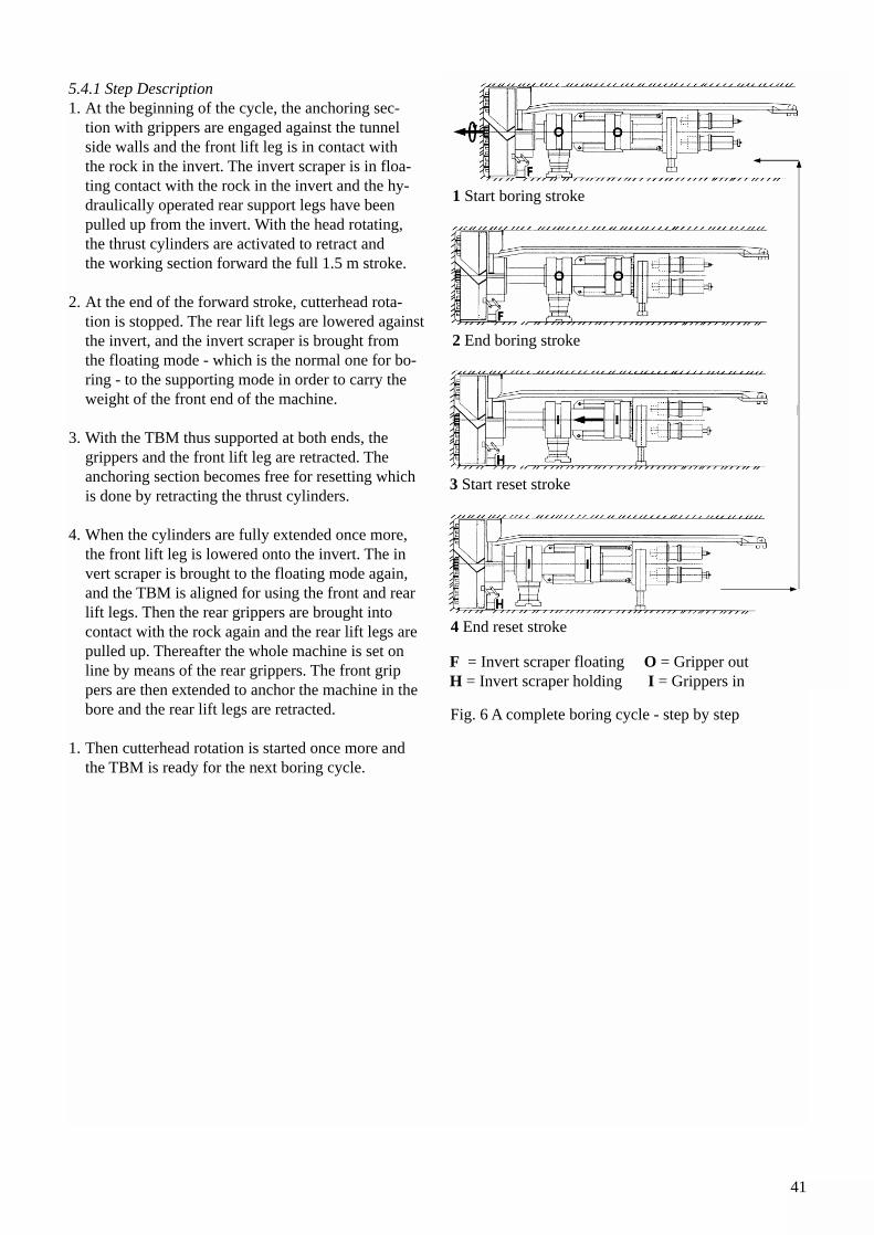
41
5.4.1 Step Description1. At the beginning of the cycle, the anchoring sec-
tion with grippers are engaged against the tunnel side walls and the front lift leg is in contact with the rock in the invert. The invert scraper is in floa-ting contact with the rock in the invert and the hy-draulically operated rear support legs have been pulled up from the invert. With the head rotating, the thrust cylinders are activated to retract and the working section forward the full 1.5 m stroke.
2. At the end of the forward stroke, cutterhead rota-tion is stopped. The rear lift legs are lowered againstthe invert, and the invert scraper is brought from the floating mode - which is the normal one for bo-ring - to the supporting mode in order to carry the weight of the front end of the machine.
3. With the TBM thus supported at both ends, the grippers and the front lift leg are retracted. The anchoring section becomes free for resetting which is done by retracting the thrust cylinders.
4. When the cylinders are fully extended once more, the front lift leg is lowered onto the invert. The invert scraper is brought to the floating mode again, and the TBM is aligned for using the front and rear lift legs. Then the rear grippers are brought into contact with the rock again and the rear lift legs are pulled up. Thereafter the whole machine is set on line by means of the rear grippers. The front grippers are then extended to anchor the machine in the bore and the rear lift legs are retracted.
1. Then cutterhead rotation is started once more and the TBM is ready for the next boring cycle.
Fig. 6 A complete boring cycle - step by step
1 Start boring stroke
2 End boring stroke
3 Start reset stroke
4 End reset stroke
F = Invert scraper floatingH = Invert scraper holding
O = Gripper outI = Grippers in

42
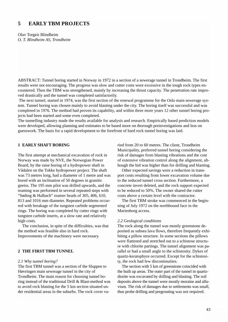
43
1 EARLY SHAFT BORING
The first attempt at mechanical excavation of rock inNorway was made by NVE, the Norwegian PowerBoard, by the raise boring of a hydropower shaft inVådalen on the Tokke hydropower project. The shaftwas 73 metres long, had a diameter of 1 metre and wasbored with an inclination of 50 degrees in graniticgneiss. The 195 mm pilot was drilled upwards, and thereaming was performed in several repeated steps with“Søding & Halbach” reamer heads of 305, 406, 610,813 and 1016 mm diameter. Repeated problems occur-red with breakage of the tungsten carbide segmentedrings. The boring was completed by cutter rings withtungsten carbide inserts, at a slow rate and relativelyhigh costs.
The conclusion, in spite of the difficulties, was thatthe method was feasible also in hard rock.Improvements of the machinery were necessary.
2 THE FIRST TBM TUNNEL
2.1 Why tunnel boring?The first TBM tunnel was a section of the Sluppen toHøvringen main sewerage tunnel in the city ofTrondheim. The main reason for choosing tunnel bo-ring instead of the traditional Drill & Blast-method wasto avoid rock blasting for the 5 km section situated un-der residential areas in the suburbs. The rock cover va-
ried from 20 to 60 metres. The client, TrondheimMunicipality, preferred tunnel boring considering therisk of damages from blasting vibrations and the costof extensive vibration control along the alignment, alt-hough the bid was higher than for drilling and blasting.
Other expected savings were a reduction in trans-port costs resulting from lower excavation volume dueto the reduced tunnel cross section. Furthermore, aconcrete invert deleted, and the rock support expectedto be reduced to 50%. The owner shared the cuttercosts above a certain level with the contractor.
The first TBM stroke was commenced in the begin-ning of July 1972 on the northbound face in theMarienborg access.
2.2 Geological conditionsThe rock along the tunnel was mostly greenstone de-posited as subsea lava flows, therefore frequently exhi-biting a pillow structure. In some sections the pillowswere flattened and stretched out to a schistose structu-re with chlorite partings. The tunnel alignment was pa-rallel or had a small angle to the schistosity. Dykes ofquartz-keratophyre occurred. Except for the schistosi-ty, the rock had few discontinuities.
The section with 5 km of greenstone coincided withthe built up areas. The outer part of the tunnel in quartz-diorite was excavated by drilling and blasting. The soildeposits above the tunnel were mostly moraine and allu-vium. The risk of damages due to settlements was small,thus probe drilling and pregrouting was not required.
5 EARLY TBM PROJECTS
Olav Torgeir BlindheimO. T. Blindheim AS, Trondheim
ABSTRACT: Tunnel boring started in Norway in 1972 in a section of a sewerage tunnel in Trondheim. The firstresults were not encouraging. The progress was slow and cutter costs were excessive in the tough rock types en-countered. Then the TBM was strengthened, mainly by increasing the thrust capacity. The penetration rate impro-ved drastically and the tunnel was completed satisfactorily.The next tunnel, started in 1974, was the first section of the renewal programme for the Oslo main sewerage sys-tem. Tunnel boring was chosen mainly to avoid blasting under the city. The boring itself was successful and wascompleted in 1976. The method had proven its capability, and within three more years 12 other tunnel boring pro-jects had been started and some even completed. The tunnelling industry made the results available for analysis and research. Empirically based prediction modelswere developed, allowing planning and estimates to be based more on thorough preinvestigations and less onguesswork. The basis for a rapid development to the forefront of hard rock tunnel boring was laid.
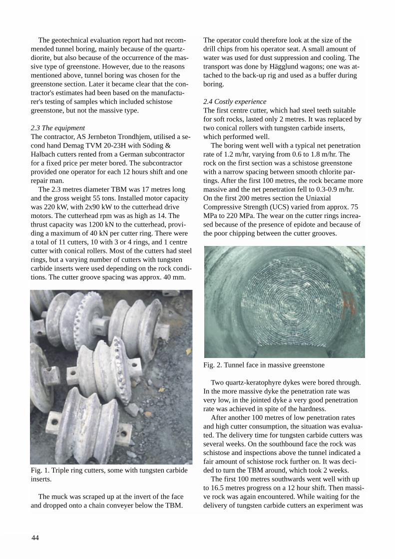
44
The geotechnical evaluation report had not recom-mended tunnel boring, mainly because of the quartz-diorite, but also because of the occurrence of the mas-sive type of greenstone. However, due to the reasonsmentioned above, tunnel boring was chosen for thegreenstone section. Later it became clear that the con-tractor's estimates had been based on the manufactu-rer's testing of samples which included schistose greenstone, but not the massive type.
2.3 The equipment The contractor, AS Jernbeton Trondhjem, utilised a se-cond hand Demag TVM 20-23H with Söding &Halbach cutters rented from a German subcontractorfor a fixed price per meter bored. The subcontractorprovided one operator for each 12 hours shift and onerepair man.
The 2.3 metres diameter TBM was 17 metres longand the gross weight 55 tons. Installed motor capacitywas 220 kW, with 2x90 kW to the cutterhead drivemotors. The cutterhead rpm was as high as 14. Thethrust capacity was 1200 kN to the cutterhead, provi-ding a maximum of 40 kN per cutter ring. There werea total of 11 cutters, 10 with 3 or 4 rings, and 1 centrecutter with conical rollers. Most of the cutters had steelrings, but a varying number of cutters with tungstencarbide inserts were used depending on the rock condi-tions. The cutter groove spacing was approx. 40 mm.
Fig. 1. Triple ring cutters, some with tungsten carbideinserts.
The muck was scraped up at the invert of the faceand dropped onto a chain conveyer below the TBM.
The operator could therefore look at the size of thedrill chips from his operator seat. A small amount ofwater was used for dust suppression and cooling. Thetransport was done by Hägglund wagons; one was at-tached to the back-up rig and used as a buffer duringboring.
2.4 Costly experienceThe first centre cutter, which had steel teeth suitablefor soft rocks, lasted only 2 metres. It was replaced bytwo conical rollers with tungsten carbide inserts,which performed well.
The boring went well with a typical net penetrationrate of 1.2 m/hr, varying from 0.6 to 1.8 m/hr. Therock on the first section was a schistose greenstonewith a narrow spacing between smooth chlorite par-tings. After the first 100 metres, the rock became moremassive and the net penetration fell to 0.3-0.9 m/hr.On the first 200 metres section the UniaxialCompressive Strength (UCS) varied from approx. 75MPa to 220 MPa. The wear on the cutter rings increa-sed because of the presence of epidote and because ofthe poor chipping between the cutter grooves.
Fig. 2. Tunnel face in massive greenstone
Two quartz-keratophyre dykes were bored through.In the more massive dyke the penetration rate wasvery low, in the jointed dyke a very good penetrationrate was achieved in spite of the hardness.
After another 100 metres of low penetration ratesand high cutter consumption, the situation was evalua-ted. The delivery time for tungsten carbide cutters wasseveral weeks. On the southbound face the rock wasschistose and inspections above the tunnel indicated afair amount of schistose rock further on. It was deci-ded to turn the TBM around, which took 2 weeks.
The first 100 metres southwards went well with upto 16.5 metres progress on a 12 hour shift. Then massi-ve rock was again encountered. While waiting for thedelivery of tungsten carbide cutters an experiment was
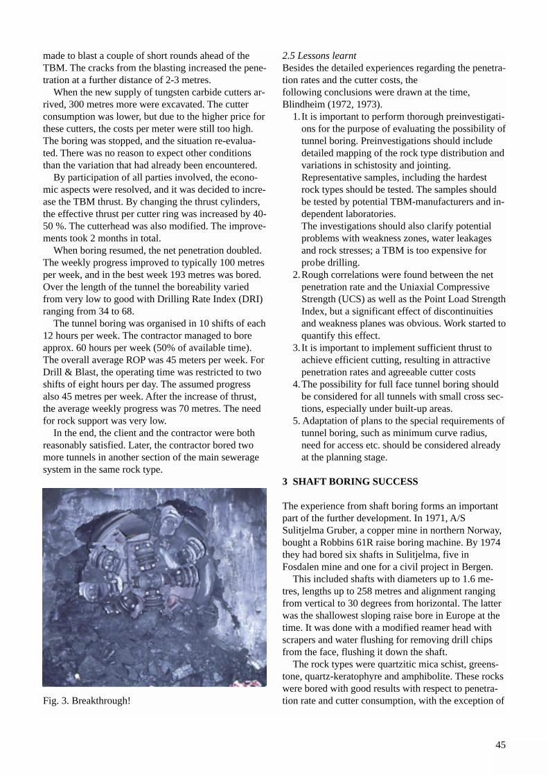
45
made to blast a couple of short rounds ahead of theTBM. The cracks from the blasting increased the pene-tration at a further distance of 2-3 metres.
When the new supply of tungsten carbide cutters ar-rived, 300 metres more were excavated. The cutterconsumption was lower, but due to the higher price forthese cutters, the costs per meter were still too high.The boring was stopped, and the situation re-evalua-ted. There was no reason to expect other conditionsthan the variation that had already been encountered.
By participation of all parties involved, the econo-mic aspects were resolved, and it was decided to incre-ase the TBM thrust. By changing the thrust cylinders,the effective thrust per cutter ring was increased by 40-50 %. The cutterhead was also modified. The improve-ments took 2 months in total.
When boring resumed, the net penetration doubled.The weekly progress improved to typically 100 metresper week, and in the best week 193 metres was bored.Over the length of the tunnel the boreability variedfrom very low to good with Drilling Rate Index (DRI)ranging from 34 to 68.
The tunnel boring was organised in 10 shifts of each12 hours per week. The contractor managed to boreapprox. 60 hours per week (50% of available time).The overall average ROP was 45 meters per week. ForDrill & Blast, the operating time was restricted to twoshifts of eight hours per day. The assumed progressalso 45 metres per week. After the increase of thrust,the average weekly progress was 70 metres. The needfor rock support was very low.
In the end, the client and the contractor were bothreasonably satisfied. Later, the contractor bored twomore tunnels in another section of the main seweragesystem in the same rock type.
Fig. 3. Breakthrough!
2.5 Lessons learntBesides the detailed experiences regarding the penetra-tion rates and the cutter costs, thefollowing conclusions were drawn at the time,Blindheim (1972, 1973).
1. It is important to perform thorough preinvestigati-ons for the purpose of evaluating the possibility oftunnel boring. Preinvestigations should include detailed mapping of the rock type distribution andvariations in schistosity and jointing. Representative samples, including the hardest rock types should be tested. The samples should be tested by potential TBM-manufacturers and in-dependent laboratories.The investigations should also clarify potential problems with weakness zones, water leakages and rock stresses; a TBM is too expensive for probe drilling.
2.Rough correlations were found between the net penetration rate and the Uniaxial Compressive Strength (UCS) as well as the Point Load StrengthIndex, but a significant effect of discontinuities and weakness planes was obvious. Work started toquantify this effect.
3. It is important to implement sufficient thrust to achieve efficient cutting, resulting in attractive penetration rates and agreeable cutter costs
4.The possibility for full face tunnel boring should be considered for all tunnels with small cross sec-tions, especially under built-up areas.
5. Adaptation of plans to the special requirements oftunnel boring, such as minimum curve radius, need for access etc. should be considered already at the planning stage.
3 SHAFT BORING SUCCESS
The experience from shaft boring forms an importantpart of the further development. In 1971, A/SSulitjelma Gruber, a copper mine in northern Norway,bought a Robbins 61R raise boring machine. By 1974they had bored six shafts in Sulitjelma, five inFosdalen mine and one for a civil project in Bergen.
This included shafts with diameters up to 1.6 me-tres, lengths up to 258 metres and alignment rangingfrom vertical to 30 degrees from horizontal. The latterwas the shallowest sloping raise bore in Europe at thetime. It was done with a modified reamer head withscrapers and water flushing for removing drill chipsfrom the face, flushing it down the shaft.
The rock types were quartzitic mica schist, greens-tone, quartz-keratophyre and amphibolite. These rockswere bored with good results with respect to penetra-tion rate and cutter consumption, with the exception of
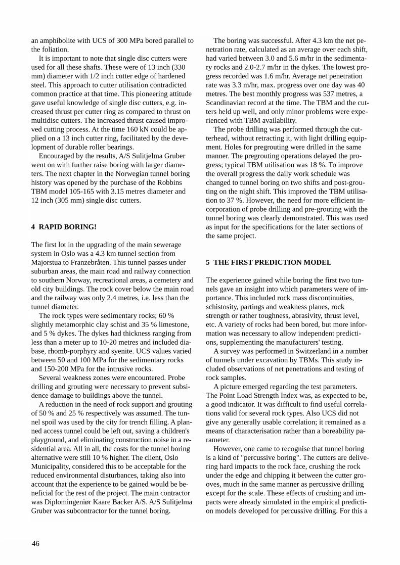
46
an amphibolite with UCS of 300 MPa bored parallel tothe foliation.
It is important to note that single disc cutters wereused for all these shafts. These were of 13 inch (330mm) diameter with 1/2 inch cutter edge of hardenedsteel. This approach to cutter utilisation contradictedcommon practice at that time. This pioneering attitudegave useful knowledge of single disc cutters, e.g. in-creased thrust per cutter ring as compared to thrust onmultidisc cutters. The increased thrust caused impro-ved cutting process. At the time 160 kN could be ap-plied on a 13 inch cutter ring, facilitated by the deve-lopment of durable roller bearings.
Encouraged by the results, A/S Sulitjelma Gruberwent on with further raise boring with larger diame-ters. The next chapter in the Norwegian tunnel boringhistory was opened by the purchase of the RobbinsTBM model 105-165 with 3.15 metres diameter and12 inch (305 mm) single disc cutters.
4 RAPID BORING!
The first lot in the upgrading of the main seweragesystem in Oslo was a 4.3 km tunnel section fromMajorstua to Franzebråten. This tunnel passes undersuburban areas, the main road and railway connectionto southern Norway, recreational areas, a cemetery andold city buildings. The rock cover below the main roadand the railway was only 2.4 metres, i.e. less than thetunnel diameter.
The rock types were sedimentary rocks; 60 %slightly metamorphic clay schist and 35 % limestone,and 5 % dykes. The dykes had thickness ranging fromless than a meter up to 10-20 metres and included dia-base, rhomb-porphyry and syenite. UCS values variedbetween 50 and 100 MPa for the sedimentary rocksand 150-200 MPa for the intrusive rocks.
Several weakness zones were encountered. Probedrilling and grouting were necessary to prevent subsi-dence damage to buildings above the tunnel.
A reduction in the need of rock support and groutingof 50 % and 25 % respectively was assumed. The tun-nel spoil was used by the city for trench filling. A plan-ned access tunnel could be left out, saving a children'splayground, and eliminating construction noise in a re-sidential area. All in all, the costs for the tunnel boringalternative were still 10 % higher. The client, OsloMunicipality, considered this to be acceptable for thereduced environmental disturbances, taking also intoaccount that the experience to be gained would be be-neficial for the rest of the project. The main contractorwas Diplomingeniør Kaare Backer A/S. A/S SulitjelmaGruber was subcontractor for the tunnel boring.
The boring was successful. After 4.3 km the net pe-netration rate, calculated as an average over each shift,had varied between 3.0 and 5.6 m/hr in the sedimenta-ry rocks and 2.0-2.7 m/hr in the dykes. The lowest pro-gress recorded was 1.6 m/hr. Average net penetrationrate was 3.3 m/hr, max. progress over one day was 40metres. The best monthly progress was 537 metres, aScandinavian record at the time. The TBM and the cut-ters held up well, and only minor problems were expe-rienced with TBM availability.
The probe drilling was performed through the cut-terhead, without retracting it, with light drilling equip-ment. Holes for pregrouting were drilled in the samemanner. The pregrouting operations delayed the pro-gress; typical TBM utilisation was 18 %. To improvethe overall progress the daily work schedule waschanged to tunnel boring on two shifts and post-grou-ting on the night shift. This improved the TBM utilisa-tion to 37 %. However, the need for more efficient in-corporation of probe drilling and pre-grouting with thetunnel boring was clearly demonstrated. This was usedas input for the specifications for the later sections ofthe same project.
5 THE FIRST PREDICTION MODEL
The experience gained while boring the first two tun-nels gave an insight into which parameters were of im-portance. This included rock mass discontinuities,schistosity, partings and weakness planes, rockstrength or rather toughness, abrasivity, thrust level,etc. A variety of rocks had been bored, but more infor-mation was necessary to allow independent predicti-ons, supplementing the manufacturers' testing.
A survey was performed in Switzerland in a numberof tunnels under excavation by TBMs. This study in-cluded observations of net penetrations and testing ofrock samples.
A picture emerged regarding the test parameters.The Point Load Strength Index was, as expected to be,a good indicator. It was difficult to find useful correla-tions valid for several rock types. Also UCS did notgive any generally usable correlation; it remained as ameans of characterisation rather than a boreability pa-rameter.
However, one came to recognise that tunnel boringis a kind of "percussive boring". The cutters are delive-ring hard impacts to the rock face, crushing the rockunder the edge and chipping it between the cutter gro-oves, much in the same manner as percussive drillingexcept for the scale. These effects of crushing and im-pacts were already simulated in the empirical predicti-on models developed for percussive drilling. For this a
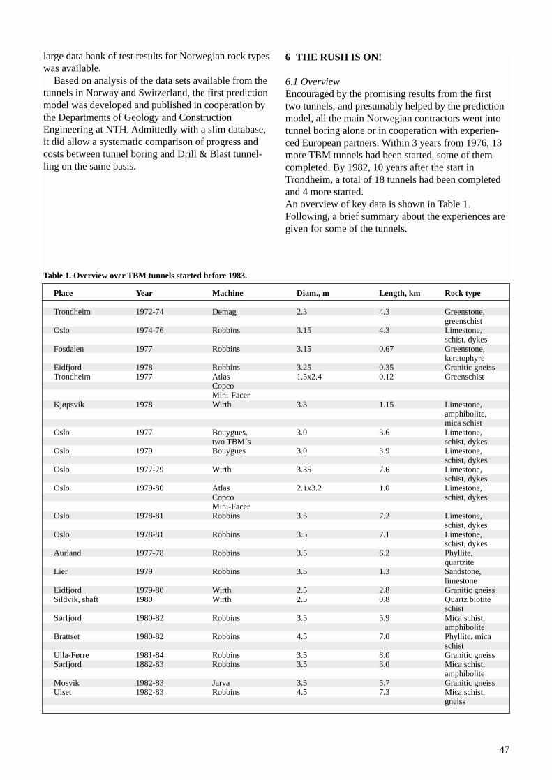
47
large data bank of test results for Norwegian rock typeswas available.
Based on analysis of the data sets available from thetunnels in Norway and Switzerland, the first predictionmodel was developed and published in cooperation bythe Departments of Geology and ConstructionEngineering at NTH. Admittedly with a slim database,it did allow a systematic comparison of progress andcosts between tunnel boring and Drill & Blast tunnel-ling on the same basis.
6 THE RUSH IS ON!
6.1 OverviewEncouraged by the promising results from the firsttwo tunnels, and presumably helped by the predictionmodel, all the main Norwegian contractors went intotunnel boring alone or in cooperation with experien-ced European partners. Within 3 years from 1976, 13more TBM tunnels had been started, some of themcompleted. By 1982, 10 years after the start inTrondheim, a total of 18 tunnels had been completedand 4 more started.An overview of key data is shown in Table 1.Following, a brief summary about the experiences aregiven for some of the tunnels.
Table 1. Overview over TBM tunnels started before 1983.
Place Year Machine Diam., m Length, km Rock type
Trondheim 1972-74 Demag 2.3 4.3 Greenstone,greenschist
Oslo 1974-76 Robbins 3.15 4.3 Limestone, schist, dykes
Fosdalen 1977 Robbins 3.15 0.67 Greenstone, keratophyre
Eidfjord 1978 Robbins 3.25 0.35 Granitic gneissTrondheim 1977 Atlas 1.5x2.4 0.12 Greenschist
Copco Mini-Facer
Kjøpsvik 1978 Wirth 3.3 1.15 Limestone, amphibolite, mica schist
Oslo 1977 Bouygues, 3.0 3.6 Limestone, two TBM´s schist, dykes
Oslo 1979 Bouygues 3.0 3.9 Limestone, schist, dykes
Oslo 1977-79 Wirth 3.35 7.6 Limestone, schist, dykes
Oslo 1979-80 Atlas 2.1x3.2 1.0 Limestone, Copco schist, dykesMini-Facer
Oslo 1978-81 Robbins 3.5 7.2 Limestone, schist, dykes
Oslo 1978-81 Robbins 3.5 7.1 Limestone, schist, dykes
Aurland 1977-78 Robbins 3.5 6.2 Phyllite, quartzite
Lier 1979 Robbins 3.5 1.3 Sandstone, limestone
Eidfjord 1979-80 Wirth 2.5 2.8 Granitic gneissSildvik, shaft 1980 Wirth 2.5 0.8 Quartz biotite
schistSørfjord 1980-82 Robbins 3.5 5.9 Mica schist,
amphiboliteBrattset 1980-82 Robbins 4.5 7.0 Phyllite, mica
schistUlla-Førre 1981-84 Robbins 3.5 8.0 Granitic gneissSørfjord 1882-83 Robbins 3.5 3.0 Mica schist,
amphiboliteMosvik 1982-83 Jarva 3.5 5.7 Granitic gneissUlset 1982-83 Robbins 4.5 7.3 Mica schist,
gneiss
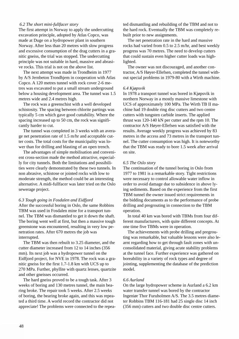
48
6.2 The short mini-fullfacer storyThe first attempt in Norway to apply the undercuttingexcavation principle, adopted by Atlas Copco, wasmade at Duge on a hydropower plant in southernNorway. After less than 20 metres with slow progressand excessive consumption of the drag cutters in a gra-nitic gneiss, the trial was stopped. The undercuttingprinciple was not suitable in hard, massive and abrasi-ve rocks. This trial is not on the above list.
The next attempt was made in Trondheim in 1977by A/S Jernbeton Trondhjem in cooperation with AtlasCopco. A 120 metres tunnel with rock cover 2-6 me-tres was excavated to put a small stream undergroundbelow a housing development area. The tunnel was 1.5metres wide and 2.4 metres high.
The rock was a greenschist with a well developedschistosity. The spacing between chlorite partings wastypically 5 cm which gave good cuttability. Where thespacing increased up to 50 cm, the rock was signifi-cantly harder to cut.
The tunnel was completed in 3 weeks with an avera-ge net penetration rate of 1.5 m/hr and acceptable cut-ter costs. The total costs for the municipality was lo-wer than for drilling and blasting of an open trench.
The advantages of simple mobilisation and conveni-ent cross-section made the method attractive, especial-ly for city tunnels. Both the limitations and possibili-ties were clearly demonstrated by these two tunnels. Innon abrasive, schistose or jointed rocks with low tomoderate strength, the method could be an interestingalternative. A midi-fullfacer was later tried on the Oslosewerage project.
6.3 Tough going in Fosdalen and EidfjordAfter the successful boring in Oslo, the same RobbinsTBM was used in Fosdalen mine for a transport tun-nel. The TBM was dismantled to get it down the shaft.The boring went well at first, but then a massive toughgreenstone was encountered, resulting in very low pe-netration rates. After 670 metres the job was interrupted.
The TBM was then rebuilt to 3.25 diameter, and thecutter diameter increased from 12 to 14 inches (356mm). Its next job was a hydropower tunnel on theEidfjord project, for NVE in 1978. The rock was a gra-nitic gneiss for the first 1.7-1.8 km with UCS up to270 MPa. Further, phyllite with quartz lenses, quartziteand other gneisses occurred.
The hard gneiss proved to be a tough task. After 3weeks of boring and 130 metres tunnel, the main bea-ring broke. The repair took 5 weeks. After 2.5 weeksof boring, the bearing broke again, and this was repea-ted a third time. A world record the contractor did notappreciate! The problems were connected to the repea-
ted dismantling and rebuilding of the TBM and not tothe hard rock. Eventually the TBM was completely re-built prior to new assignments.
The net penetration rate in the hard and massiverocks had varied from 0.5 to 2.5 m/hr, and best weeklyprogress was 70 metres. The need to develop cuttersthat could sustain even higher cutter loads was high-lighted.
The owner was not discouraged, and another con-tractor, A/S Høyer-Ellefsen, completed the tunnel with-out special problems in 1979-80 with a Wirth machine.
6.4 KjøpsvikIn 1978 a transport tunnel was bored in Kjøpsvik innorthern Norway in a mostly massive limestone withUCS of approximately 100 MPa. The Wirth TB II ma-chine had 19 double ring disc cutters and two centrecutters with tungsten carbide inserts. The appliedthrust was 120-140 kN per cutter and the rpm 10. Thecontractor A/S Høyer-Ellefsen was satisfied with theresults. Average weekly progress was achieved by 83metres in the access and 73 metres in the transport tun-nel. The cutter consumption was high. It is noteworthythat the TBM was ready to bore 1.5 week after arrivalon site.
6.5 The Oslo storyThe continuation of the tunnel boring in Oslo from1977 to 1981 is a remarkable story. Tight restrictionswere necessary to control allowable water inflow inorder to avoid damage due to subsidence in above ly-ing sediments. Based on the experience from the firstTBM tunnel the owner issued strict requirements inthe bidding documents as to the performance of probedrilling and pregrouting in connection to the TBMoperation.
In total 40 km was bored with TBMs from four dif-ferent manufacturers, with quite different concepts. Atone time five TBMs were in operation.
The achievements with probe drilling and pregrou-ting was remarkable, but valuable lessons were also le-arnt regarding how to get through fault zones with un-consolidated material, giving acute stability problemsat the tunnel face. Further experience was gathered onboreability in a variety of rock types and degree ofjointing, supplementing the database of the predictionmodel.
6.6 AurlandOn the large hydropower scheme in Aurland a 6.2 kmwater transfer tunnel was bored by the contractorIngeniør Thor Furuholmen A/S. The 3.5 metres diame-ter Robbins TBM 116-181 had 25 single disc 14 inch(356 mm) cutters and two double disc centre cutters.
49
The rpm was 7.2. The rock types were phyllites withsmaller and larger lenses of quartz and sections of ametamorphic sandstone with a quartz content of 40%.Fig. 4. Single disc cutters
The tunnel boring started the summer of 1977 andtowards the end of 1978, 5.9 km had been bored.Progress on the best day was 35.2 metres, the bestweek 181 metres and the best month 651 metres.Average net penetration rate had been 1.9 m/hr andoverall progress 108 metres per week. TBM utilisationwas 63 %, best week 72 %.
For long sections the schistose rock was bored inthe most difficult direction, i.e. parallel to the tunnelaxis. A series of tests was performed with the TBMchecking the relation between penetration rate andthrust, demonstrating the significant effect of higherthrust. During normal boring 145 kN per cutter wasused, which was 80 % of the rated cutter capacity. Thisproved most economical for disc rings and bearings. Inshort periods the TBM bored up to 7.3 m/hr, fully utili-sing the torque of the 4 drive motors.
The cutter costs were higher than estimated, up toUSD 20-25 per metre tunnel in the quartzitic sandsto-ne. No rock support was installed during excavation,and the need for permanent support was minimal. Thecosts per metre tunnel were still higher than for Drill& Blast tunnelling, but the reduced construction timecould be used, allowing earlier transfer of water.
The Aurland tunnel became important for the fur-ther development of the prediction models.Comparable data sets made it possible to quantify theeffect of the angle between the foliation and the tunnelaxis. It was found that the net penetration rate increa-sed in proportion to the angle; e.g. in the phyllite a 45degree angle gave a 45 % increase. This was includedin the next revision of the prediction model togetherwith similar data from other tunnels.
6.7 LierAfter completion in Aurland in 1978, Ingeniør ThorFuruholmen A/S put the Robbins TBM 116-181 to useon a water transfer tunnel from Holsfjorden andLierdalen, near Oslo. The rocks in the 3,600 metreslong 3.5 metres diameter tunnel were clay schist, li-mestone, mudstone and sandstone. After boring 1,262metres the best daily and weekly progress were 42 and144 metres respectively. In rock with medium boreabi-lity (DRI=53 and BWI=23) an average net penetrationof 3.7 m/hr was achieved.
The overall results did not meet the expectations, asthe TBM availability was low due to several mechani-cal, electrical and hydraulic problems. A cave-in of 50m3 rock above and on the side of the TBM occurred ina wet zone of blocky sandstone with slickensidedjoints. Minimal damage occurred, but it took four weeks to clear out the debris manually, install steel lining segments and pour concrete behind the seg-ments to resume boring.
This demonstrated that good net penetration is notenough. Progress depends on TBM utilisation, TBMavailability and rock stability problems.
6.8 SørfjordIn 1981-82, the same 3.5 metres Robbins TBM 116-181 bored the 5.9 km Brynsvatn-Nikkelv tunnel and in1982-83 the 3.0 km Nikkelv-Vatn tunnel for theSørfjorden Hydropower Project, through mica-schist,gneiss and amphibolite.
The achieved penetration rate was on the average2.1 m/hr in mica-schist (DRI approx. 75) and 1.4 m/hrin gneiss and amphibolite (DRI approx. 50). Thegneiss and amphibolite had no jointing of significanteffect for the penetration, whereas the foliation of themica schist improved the boreability significantly.
Overall progress was 130 and 105 metres per weekfor the 5,836 metres and 3,030 metres sections respec-tively. Best weekly progress was 240.5 metres and bestmonthly 775 metres. Cutter costs were as expected, atabout 2-4 USD per m3. It was concluded that the re-sults were satisfactory with respect to technical perfor-mance, time and costs both for the owner and the con-tractor.
6.9 Revised prediction model With results from other tunnels, a large amount of ex-perience data was now available. This was due to thewillingness of the owners, contractors and manufactu-rers to provide access for follow up and testing duringand after construction, and the openness with detailedand overall results. The NTH prediction model wasagain revised, including all relevant parameters, sup-ported by an extensive database.
50
7 CONCLUSIONS
During the first ten years of tunnel boring, the use hadincreased to a significant portion of the total tunnel-ling. Experience was gained regarding a variety ofrock conditions and technical problems. The mainpoints regarding what had been achieved and what wasto be expected was summarised as follows:
• Disc cutters were effective for both raise and tunnel boring in hard rock, and the importance of utilising high thrust levels had been demonstrated.
• The undercutting principle with drag cutters could be used in weak rock with low abrasivity. Medium hard rock could be bored when jointed.
• Discontinuities and different types of weakness pla-nes in the rock mass; bedding planes, foliation, par-tings etc., have a pronounced effect on the borea-bility of the rock mass. Efforts to quantify the effect had made significant progress.
• Because the owners, contractors and manufacturers had showed openness about achieved results, a use-ful prediction model for TBM performance had been developed. This was available as a planning and follow-up tool, making it feasible to consider the advantages of tunnel boring already at the plan-ning stage by adapting plant layouts to the possibili-ties of faster tunnelling, longer drives etc. It could also serve as a basis for risk sharing between the client and the contractor.
• Tunnel boring in massive and abrasive rocks had been performed with good results by TBMs with single disc cutters sustaining high thrust levels.
• Systematic probe drilling and pregrouting could be combined with tunnel boring by proper preparation of the TBM.
• Efficient boring through weakness zones and secti-ons with high rock stresses by utilising light supportelements and rock bolts had been achieved.
• Several cave-ins in unconsolidated crushed zones causing delays had been experienced. Methods to avoid cave-ins, or to pass through should they occur, had been improved.
• Boring of inclined shafts with TBMs had proven to be an efficient and safe method.
• High TBM utilisation was necessary for good pro-gress. The importance of an effective organisation and good backup systems had been demonstrated and remarkable results achieved.
It was concluded that tunnel boring was more sensi-tive in respect to organisation and geological conditi-ons than Drill & Blast tunnelling. The use of TBMs
with even higher cutter capacity would open the possi-bility to boring longer and larger tunnels in even har-der rocks. The prediction model provided a tool forchoosing between tunnel boring and Drill & Blast tun-nelling in a balanced manner. The basis for a furtherdevelopment to the forefront of hard rock tunnel bo-ring, mastering also the potential difficulties with highrock stresses, fault zones, water etc., had been laid.
LITERATURE
Holen, H. (1967): "Tests with full face boring ofshafts", Rock Blasting Conference, Oslo (InNorwegian)
Selmer-Olsen, R. & Blindheim, O. T. (1970): "On thedrillability of rocks by percussive drilling".Proc. Int. ISRM 2nd Conf. on Rock Mechanics,Belgrade.
Lien, R. (1971, 1979): "Classification of rocks with respect to drillability". Rock Blasting Conference,Oslo (In Norwegian)
Blindheim, O. T. (1972): "Experience from full faceboring in greenstone", Rock Blasting Conference, Oslo(In Norwegian)
Blindheim, O. T. (1973): "New experiences with fullface boring", Rock Blasting Conference, Oslo (InNorwegian)
Hansen, A. (1974): "Full face boring of shafts, new experiences", Rock Blasting Conference, Oslo (InNorwegian)
Hansen, A. (1975): "Full face boring of tunnelFranzebråten-Majorstua", Rock Blasting Conference,Oslo (In Norwegian)
Blindheim, O. T. (1976): "Geological parameters andfull face boring. Cost predictions", Rock BlastingConference, Oslo (In Norwegian)
Blindheim, O. T, Johansen, E. D. & Johannessen, O.(1976): "Criteria for the selection of full face tunnelboring or conventional tunnelling", Proc. ISRM 4thConf. on Rock Mechanics, Montreux
Blindheim, O. T. (1977): "Minifullfacer in green-stone", Rock Blasting Conference, Oslo (In Norwegian)
51
Hansen, A. (1977): "Information about full face boringfor Fosdalen mine and NVE", Rock BlastingConference, Oslo (In Norwegian) Hansen, A. (1978): "Full face boring of tunnel.Experience from Eidfjord", Rock Blasting Conference,Oslo (In Norwegian)
Askildsrud, O. G. (1978): "Experience from Aurland",Rock Blasting Conference, Oslo (In Norwegian)
Skjeggedal. T. (1978): "Full face boring. Experiencefrom Kjøpsvik and Bærum", Rock BlastingConference, Oslo (In Norwegian)
Skjeggedal, T. (1979): "New experiences with full facetunnel boring in Bærum and Eidfjord", Rock BlastingConference, Oslo (In Norwegian)Askildsrud, O. G. (1979): "Recent TBM experience inthe Oslo region", Rock Blasting Conference, Oslo (InNorwegian)
Blindheim, O. T. & Johansen, E. D. (1979): "New prediction model for progress and costs for full faceboring of tunnels", Rock Blasting Conference, Oslo
(In Norwegian)Blindheim, O. T. (1979): "Failure mechanisms underdisc cutters. Factors influencing the boring process byfullface tunnel boring", Rock Mechanics Conference,Oslo (In Norwegian)
Blindheim, O. T. (1981): "Norwegian fullface tunnelboring. What is done - what is next?", Rock BlastingConference, Oslo (In Norwegian)
Blindheim, O. T. (1982): "Recent experience about theinfluence of discontinuities on boreability and stabilityby fullface tunnel boring", Rock Blasting Conference,Oslo (In Norwegian)
Kaarød, S. (1983): "Full face boring. Experience fromSørfjorden", Rock Blasting Conference, Oslo (InNorwegian)
Johannessen, O. (1983): "New prediction model forfullface tunnel boring", Rock Blasting Conference,Oslo (In Norwegian)

52
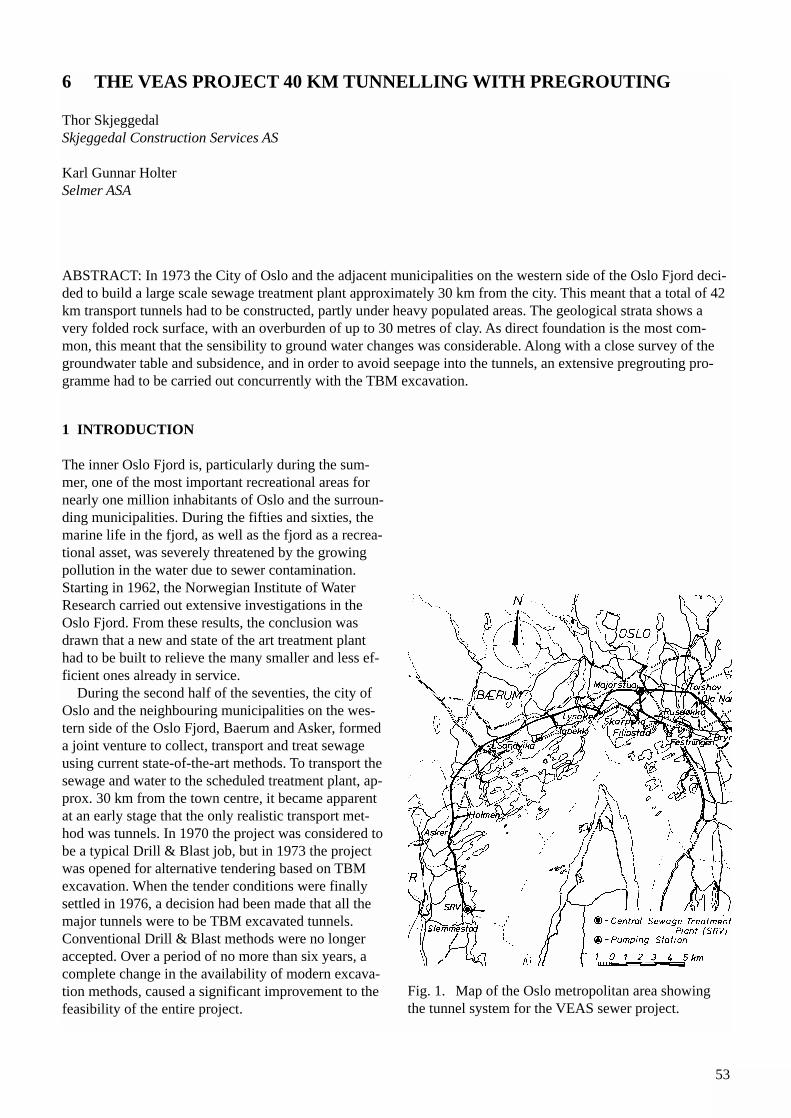
53
1 INTRODUCTION
The inner Oslo Fjord is, particularly during the sum-mer, one of the most important recreational areas fornearly one million inhabitants of Oslo and the surroun-ding municipalities. During the fifties and sixties, themarine life in the fjord, as well as the fjord as a recrea-tional asset, was severely threatened by the growingpollution in the water due to sewer contamination.Starting in 1962, the Norwegian Institute of WaterResearch carried out extensive investigations in theOslo Fjord. From these results, the conclusion wasdrawn that a new and state of the art treatment planthad to be built to relieve the many smaller and less ef-ficient ones already in service.
During the second half of the seventies, the city ofOslo and the neighbouring municipalities on the wes-tern side of the Oslo Fjord, Baerum and Asker, formeda joint venture to collect, transport and treat sewageusing current state-of-the-art methods. To transport thesewage and water to the scheduled treatment plant, ap-prox. 30 km from the town centre, it became apparentat an early stage that the only realistic transport met-hod was tunnels. In 1970 the project was considered tobe a typical Drill & Blast job, but in 1973 the projectwas opened for alternative tendering based on TBMexcavation. When the tender conditions were finallysettled in 1976, a decision had been made that all themajor tunnels were to be TBM excavated tunnels.Conventional Drill & Blast methods were no longeraccepted. Over a period of no more than six years, acomplete change in the availability of modern excava-tion methods, caused a significant improvement to thefeasibility of the entire project.
Fig. 1. Map of the Oslo metropolitan area showingthe tunnel system for the VEAS sewer project.
6 THE VEAS PROJECT 40 KM TUNNELLING WITH PREGROUTING
Thor Skjeggedal Skjeggedal Construction Services AS
Karl Gunnar HolterSelmer ASA
ABSTRACT: In 1973 the City of Oslo and the adjacent municipalities on the western side of the Oslo Fjord deci-ded to build a large scale sewage treatment plant approximately 30 km from the city. This meant that a total of 42km transport tunnels had to be constructed, partly under heavy populated areas. The geological strata shows avery folded rock surface, with an overburden of up to 30 metres of clay. As direct foundation is the most com-mon, this meant that the sensibility to ground water changes was considerable. Along with a close survey of thegroundwater table and subsidence, and in order to avoid seepage into the tunnels, an extensive pregrouting pro-gramme had to be carried out concurrently with the TBM excavation.
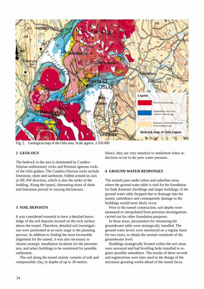
54
2 GEOLOGY
The bedrock in the area is dominated by Cambro-Silurian sedimentary rocks and Permian igneous rocksof the Oslo graben. The Cambro-Silurian rocks includelimestone, shale and sandstone, folded around an axisin NE-SW direction, which is also the strike of thebedding. Along the tunnel, alternating strata of shaleand limestone prevail in varying thicknesses.
3 SOIL DEPOSITS
It was considered essential to have a detailed know-ledge of the soil deposits located on the rock surfaceabove the tunnel. Therefore, detailed soil investigati-ons were performed at an early stage in the planningprocess. In addition to finding the most favourablealignment for the tunnel, it was also necessary to choose strategic installation locations for the piezome-ters, and select buildings to be monitored for possiblesettlement.
The soil along the tunnel mainly consists of soft andcompressible clay, in depths of up to 30 metres.
Hence, they are very sensitive to settlement when re-ductions occur in the pore water pressure.
4 GROUND WATER RESPONSES
The tunnels pass under urban and suburban areas where the ground water table is vital for the foundationfor both domestic dwellings and larger buildings. If theground water table dropped due to drainage into the tunnel, subsidence and consequently damage to the buildings would most likely occur.
Prior to the tunnel construction, soil depths weremeasured or interpolated from previous investigationscarried out for other foundation purposes.
In these areas, piezometers for measuring thegroundwater table were strategically installed. Theground water levels were monitored on a regular basisfor two years, to obtain the normal variations of thegroundwater level.
Buildings strategically located within the soil areaswere surveyed and had levelling bolts installed to re-gister possible subsidence. The results of these recordsand registrations were later used in the design of thenecessary grouting works ahead of the tunnel faces.
Rock of permian age
Sedimentary rock fromCambro- Silurian age
Basement. Authoctonious rockof Precambrian age
Bedrock map of Oslo region
Legend
Fig. 2. Geological map of the Oslo area. Scale approx. 1:550 000
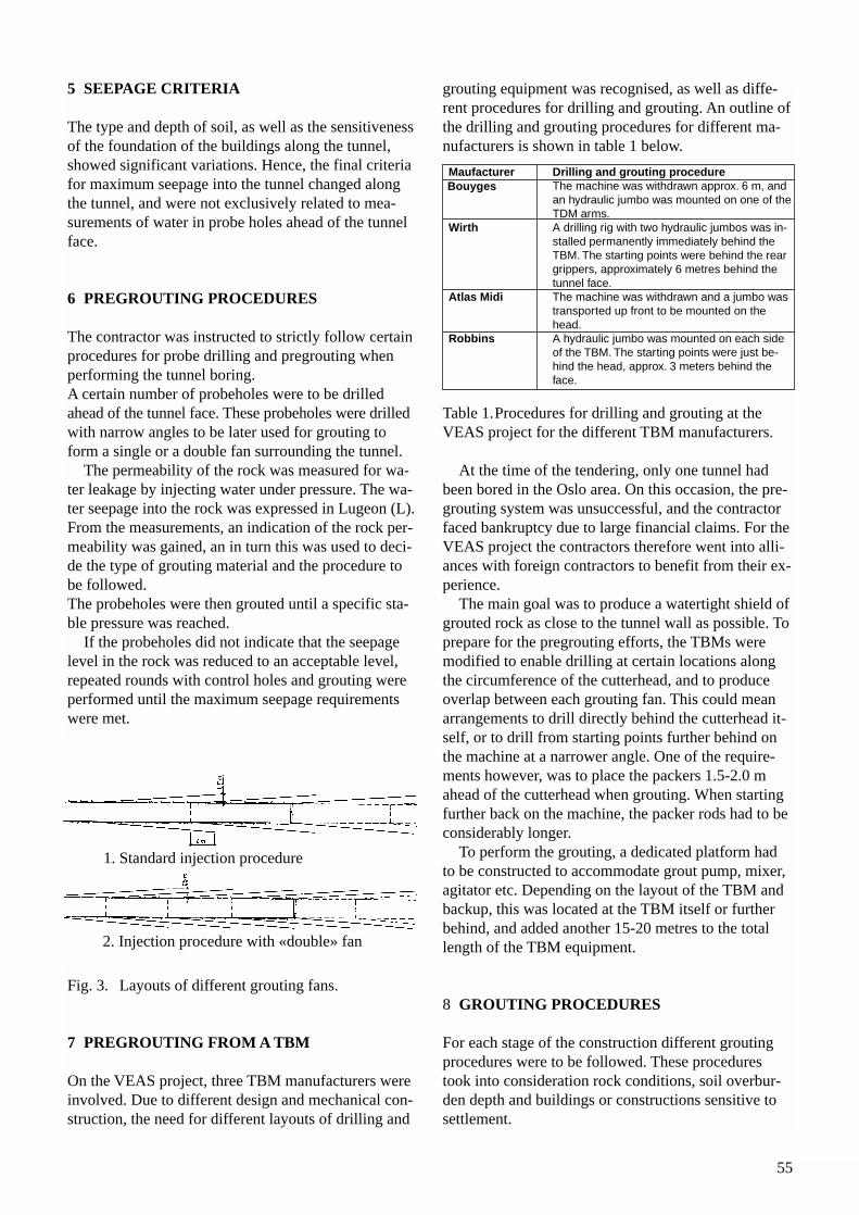
55
5 SEEPAGE CRITERIA
The type and depth of soil, as well as the sensitivenessof the foundation of the buildings along the tunnel,showed significant variations. Hence, the final criteriafor maximum seepage into the tunnel changed alongthe tunnel, and were not exclusively related to mea-surements of water in probe holes ahead of the tunnelface.
6 PREGROUTING PROCEDURES
The contractor was instructed to strictly follow certainprocedures for probe drilling and pregrouting whenperforming the tunnel boring. A certain number of probeholes were to be drilled ahead of the tunnel face. These probeholes were drilledwith narrow angles to be later used for grouting toform a single or a double fan surrounding the tunnel.
The permeability of the rock was measured for wa-ter leakage by injecting water under pressure. The wa-ter seepage into the rock was expressed in Lugeon (L).From the measurements, an indication of the rock per-meability was gained, an in turn this was used to deci-de the type of grouting material and the procedure tobe followed.The probeholes were then grouted until a specific sta-ble pressure was reached.
If the probeholes did not indicate that the seepagelevel in the rock was reduced to an acceptable level,repeated rounds with control holes and grouting wereperformed until the maximum seepage requirementswere met.
Fig. 3. Layouts of different grouting fans.
7 PREGROUTING FROM A TBM
On the VEAS project, three TBM manufacturers wereinvolved. Due to different design and mechanical con-struction, the need for different layouts of drilling and
grouting equipment was recognised, as well as diffe-rent procedures for drilling and grouting. An outline ofthe drilling and grouting procedures for different ma-nufacturers is shown in table 1 below.
Table 1.Procedures for drilling and grouting at theVEAS project for the different TBM manufacturers.
At the time of the tendering, only one tunnel hadbeen bored in the Oslo area. On this occasion, the pre-grouting system was unsuccessful, and the contractorfaced bankruptcy due to large financial claims. For theVEAS project the contractors therefore went into alli-ances with foreign contractors to benefit from their ex-perience.
The main goal was to produce a watertight shield ofgrouted rock as close to the tunnel wall as possible. Toprepare for the pregrouting efforts, the TBMs weremodified to enable drilling at certain locations alongthe circumference of the cutterhead, and to produceoverlap between each grouting fan. This could meanarrangements to drill directly behind the cutterhead it-self, or to drill from starting points further behind onthe machine at a narrower angle. One of the require-ments however, was to place the packers 1.5-2.0 mahead of the cutterhead when grouting. When startingfurther back on the machine, the packer rods had to beconsiderably longer.
To perform the grouting, a dedicated platform hadto be constructed to accommodate grout pump, mixer,agitator etc. Depending on the layout of the TBM andbackup, this was located at the TBM itself or furtherbehind, and added another 15-20 metres to the totallength of the TBM equipment.
8 GROUTING PROCEDURES
For each stage of the construction different groutingprocedures were to be followed. These procedurestook into consideration rock conditions, soil overbur-den depth and buildings or constructions sensitive tosettlement.
1. Standard injection procedure
2. Injection procedure with «double» fan
Maufacturer Drilling and grouting procedureThe machine was withdrawn approx. 6 m, and an hydraulic jumbo was mounted on one of theTDM arms.
Wirth A drilling rig with two hydraulic jumbos was in-stalled permanently immediately behind the TBM. The starting points were behind the rear grippers, approximately 6 metres behind the tunnel face.
Atlas Midi The machine was withdrawn and a jumbo was transported up front to be mounted on the head.
Robbins A hydraulic jumbo was mounted on each side of the TBM. The starting points were just be-hind the head, approx. 3 meters behind the face.
Bouyges
56
The main grouting material was Rapid PortlandCement, a special cement mixture with a hardeningtime of less than 30 minutes. This allowed the tunnelboring to continue as soon as the grouting and waterloss measurements were carried out and met the speci-fied criteria. When the water loss was still too high, af-ter cement grouting, chemical solutions with viscosityequal to water were pumped in at high pressures to filljoints and fissures with openings less than 0.1 mm.
The effective grouting length along the tunnel axiswas approx. 25 metres. An overlap of 4 metres was re-quired in each round. Hence, the TBM could proceedapproximately 20 metres between each groutinground.
In zones with extensive faults, it was experiencedthat 25 metres is too long for one grouting round.Severe difficulties arose when drilling the probeholesand placing the packers, and grout flew back into thetunnel. The grouting length was therefore reduced to10 metres or even less when working in heavily fractu-red rock.
As mentioned, the packer rods were relatively long,approx. 7.5 metres. To be able to flush the packer rodwith water, and avoid hardening of the grouting mate-rial in the rod, a simple valve and a specially designedplastic hose were used to do this successfully. Hence,the packer rods could be reused.
The cement was transported into the tunnel in stan-dard 50 kg sacks and lifted by hand directly into themixer. Chemicals used were pumped directly from atransport tank.
For the grouting operation, a crew of five men wasneeded; The same force doing the tunnel boring.
Naturally, the grouting accounted for a relativelylarge part of the total construction time for the tunnel.
9 SEEPAGE REDUCTION
The seepage into the tunnels was given in Lugeon (L)when handling the seepage in probe holes ahead of theface during excavation. After excavation the seepagewas given in litres pr minute pr 100 m of tunnel. Forthe TBM excavated tunnels the remaining seepage wasin the range of 2 - 5 litres pr minute pr 100 m of tunnel.
In most cases, the installed piezometers showed nodrop in the groundwater level. However, a few piezo-meters showed a significant drop, and temporary infil-tration had to be utilised to compensate for the seepage.
REFERENCES
Skjeggedal, T. (1981): Pregrouting in a fullface boredtunnel. RETC Proceedings 1981.
Asting, G. (1980): Experience with pregrouting in se-wage tunnels in the Oslo area. Norwegian tunnellingconference, Oslo, 1980 (Norw.)
Storjordet, A. , Asting, G., Fredriksen, U. (1988): TheOslofjord Sewage Project. Report no 2. Work groupfor grouting methods. Unpubl. VEAS , Oslo, 1988(Norw.)
57
1 INTRODUCTION
Because of Norway's topography, most of its popula-tion is living along valleys and fjords, and therefore alarge number of road tunnels has been built. In the ear-ly eighties, approximately ten years after the start oftunnel boring in Norway, the technology had apparent-ly advanced enough to consider TBMs for the large di-ameters needed for road tunnels.
Two government organisations, the NorwegianHydropower Authority NVE *) and the Public RoadsAdministration, pioneered the use of TBMs for exca-vation of road tunnels in the period from 1984 to 1987.
*) Through a restructure of the managing of the Norwegian water resources, NVE has been divi-ded into (1) NVE, concentrating i.a. on govern-mental duties like rules, regulations, concessions, controls, safety and (2) Statkraft as the commer-cial agent of Government within hydro power.
2 HOLANDSFJORD
2.1 Project descriptionThe Svartisen Hydropower Project in northernNorway, was planned to tap the water from theSvartisen glacier. It became the scene for a lot of tun-nel boring, described in other papers in this publication.
The advantages of providing a ferry-free access toHolandsfjord for the hydropower development and thesmall townships of Kilvik and Braset with road con-nection, which could later become a part of the coastalroute, triggered a co-operation between the hydropo-wer and road authorities. This resulted in the 7.6 km
Svartisen road tunnel. NVE financed the project forthe Public Roads Administration because of the advan-tages during the development of the hydropower project. NVE also performed the tunnel boring.
The southern 5.1 km section of the tunnel had mi-caschist changing to gneissic rock towards north, witha section of embedded quartzitic sandstone. Graniticgneiss dominated the northern 2.5 km section of thetunnel.
2.2 Choice of methodThe TBM was chosen for the southern section of thetunnel, because the rocks were expected to have goodboreability, making it possible to reduce the tunnellingtime. The northern section was excavated by Drill &Blast. A private contractor was assigned this duty.
A 6.25 m diameter refurbished Robbins TBM 204-216, equipped with 44 single disc 15.5 inch cutters(not changed as for the other TBM in Kobbelv) and se-ven 200 hp drive motors, was made available by NVE.
The project management expected the TBM to ad-vance 90-100 m per week, and complete the bore inspring 1985. It was assumed that Drill & Blast tunnel-ling would have required almost a year more, due toslower excavation rate and more rock support. Thetunnel had to be ready in 1986 when the developmentof Svartisen Hydropower Project was scheduled tostart in full.
The reasons for choosing tunnel boring as compared tothe Drill & Blast method are summarised as follows:• Shorter construction period. • Reduced rock support.• Possible reuse of TBM for the headrace tunnel to
the Svartisen power station
7 BORED ROAD TUNNELS IN HARD ROCK
Olav Torgeir BlindheimO. T. Blindheim AS
Erik Dahl JohansenStatkraft Anlegg AS
Arild HegrenæsPublic Roads Administration Hordaland
ABSTRACT: The paper describes the first full-face tunnel boring and part-face road-header cutting of road tun-nels in Norway. The tunnel boring proved feasible from a technical performance viewpoint, and satisfied the re-quirements of the projects, including reduced environmental impact. At the time, tunnel boring and roadheaderexcavation could not compete with Drill & Blast with respect to costs on a meter by meter comparison. However,the experience gained has contributed significantly to the development of hard rock tunnel boring under demanding conditions.
58
• Reuse of the mobilisation facilities to construct Svartisen power station in Holandsfjord
Other aspects were:• The type of TBM and the tunnel mobilising set up
was similar to that used for another project in the vicinity, hence synergies could be expected
• Initially, it had been decided to plan for single lane traffic in the tunnel. The selected 6.25 metres dia-meter TBM would accommodate one lane. Reconsideration of the future traffic intensity called for two lanes in the tunnel. The adequate decisions were made and the cross section of the tunnel modi-fied accordingly. To obtain the requested cross sec-tion for two lanes of 3.0 metres each, an increase of the 6.25 diameter bored tunnel by means of Drill & Blast took place.
2.3 ExperienceThe contractor rented the refurbished TBM from theproducer for a fixed price per cubic metre. The rent co-vered capital costs, cutter costs and spare parts forTBM, backup equipment, muck cars and rotadump.
A landing craft was used to bring the TBM andequipment onshore at the remote site in September1983. Boring started 18.01.84, after assembly of theTBM and back up equipment, preparation of a startingchamber and the construction of the muck dumpingstation. This included excavation of 200 m of the tun-nel by Drill & Blast. Some modifications were done tothe TBM, based on the experience encountered inKobbelv with the other machine.
The back up equipment consisted of a double tracksystem with traverse shifting using 14 m3 muck cars. Arotadump was installed over a silo system at the portal.
The TBM holed through in March 1985 after 4,300m had been bored in a total of 62 weeks. The averageprogress was 80.7 m per week for the weeks actuallybored. Average net penetration was 2.0 m/h, typicallyvarying between 1 and 3 m/h. Thrust per cutter was200-220 kN. The TBM was torque limited on long sections.
The transport facilities kept pace with the boring untila penetration of 2.5-2.8 m/hr was reached. When higherpenetration rates were achieved, traffic problems occurred.
In some jointed and karstic zones heavy water in-gress was experienced. This resulted in flooding of thedump station and the silo, as well as messy workingconditions at the TBM. The wet muck ran over theconveyer belt and manual clearing of the invert wasnecessary before laying the rails.
In a zone of quartzitic sandstone, several sectionswith crushed rock were encountered, resulting in diffi-
cult conditions for bolting, fallouts over the TBM andproblems with gripping. Attempts to shore the gripperpads with timber did not work well. Steel beams werewelded to the grippers and attached to the rock behindthe zones, allowing the TBM to 'walk' slowly over theworst zones. Boring with very low thrust, resulted in0.15 m/h net penetration and 10-12 hours per 1.8 mthrust. In a section of 50 m, shotcreting was performedup to the cutterhead roof shield. Loading of fallout wasdone manually and by a small bobcat below the TBM.It took six weeks to excavate through 200 m.
It was clearly demonstrated that in poor ground itwas important to be able to perform rock support, pro-be drilling, prebolting and pregrouting immediatelybehind the cutterhead.
After breakthrough, the bored cross section of 32 m2
was enlarged by blasting.In spite of the water inflow and stability problems,
the TBM performed well. However, a comparison ofprogress and costs performed afterwards indicated clearly that tunnel boring could not compete with Drill& Blast tunnelling with respect to costs. The total costwas USD 2,600 (NOK 17,000) per m tunnel, whereasDrill & Blast would have cost one third less, even with10 times more rock support. A larger bored cross sec-tion, with no need for enlargement by blasting, wouldalso have been more costly.
The northern section of the tunnel was excavated byDrill & Blast. This granitic part cost less than half ofthe TBM section (three times more rock support included).
The principal target had, however, been achieved,and useful experience gained on tunnel boring of lar-ger cross sections. When opened for traffic, theSvartisen road tunnel was the longest road tunnel inNorway. The TBM was then moved then to theKobbelv Hydropower Project, to bore the last 2.6 kmof the headrace tunnel towards the pressure shaft.
3 FLØYFJELLET
3.1 Project descriptionBergen, Norway's second largest city, frequently na-med the city between the seven mountains, urgentlyneeded a bypass motorway system through the mostcongested area of the city. In 1982 it was decided toconstruct a double tube tunnel, each tube with twotraffic lanes under the Fløyfjellet mountain. The southbound tube would be 3.2 km and the north-bound 3.8 km.
The areas around the tunnel alignment are partly built up and there are hospitals close to both portals.
80% of the tunnel passes through mainly hard grani-
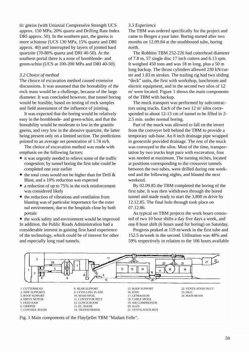
59
tic gneiss (with Uniaxial Compressive Strength UCSapprox. 150 MPa, 20% quartz and Drilling Rate IndexDRI approx. 50). In the southern part, the gneiss ismore schistose (UCS 130 MPa, 15% quartz and DRIapprox. 40) and interrupted by layers of jointed hardquartzite (70-80% quartz and DRI 40-50). At the southern portal there is a zone of hornblende- and green-schist (UCS at 100-200 MPa and DRI 40-50).
3.2 Choice of methodThe choice of excavation method caused extensivediscussions. It was assumed that the boreability of therock mass would be a challenge, because of the largediameter. It was concluded however, that tunnel boringwould be feasible, based on testing of rock samplesand field assessment of the influence of jointing.
It was expected that the boring would be relativelyeasy in the hornblende- and green-schist, and that theboreability would be moderate to low in the graniticgneiss, and very low in the abrasive quartzite, the latterbeing present only on a limited section. The predictionspointed to an average net penetration of 1.74 m/h.
The choice of excavation method was made withemphasis on the following factors:• it was urgently needed to relieve some of the traffic
congestion; by tunnel boring the first tube could be completed one year earlier
• the total costs would not be higher than for Drill & Blast, and a 10% reduction was expected
• a reduction of up to 75% in the rock reinforcement was considered likely
• the reduction of vibrations and ventilation from blasting was of particular importance for the external environment, due to the hospitals close by both portals
• the work safety and environment would be improvedIn addition, the Public Roads Administration had aconsiderable interest in gaining first hand experienceof the technology, which could be of interest for otherand especially long road tunnels.
3.3 ExperienceThe TBM was ordered specifically for the project andcame to Bergen a year later. Boring started after twomonths on 12.09.84 at the southbound tube, boringnorth.
The Robbins TBM 252-226 had cutterhead diameterof 7.8 m, 57 single disc 17 inch cutters and 6.13 rpm.It weighed 450 tons and was 18 m long, plus a 50 mlong backup. The thrust cylinders allowed 230 kN/cut-ter and 1.83 m strokes. The trailing rig had two sliding“deck” units, the first with workshop, lunchroom andelectric equipment, and in the second two silos of 12m3 were located. Figure 1 shows the main componentsof the TBM with backup.
The muck transport was performed by subcontrac-tors using trucks. Each of the two 12 m3 silos corre-sponded to about 12-13 cm of tunnel to be filled in 2-2.5 min. under normal boring.
Part of the muck was allowed to fall on the invertfrom the conveyer belt behind the TBM to provide atemporary sub-base. An 8 inch drainage pipe wrappedin geotextile provided drainage. The rest of the muckwas conveyed to the silos. Most of the time, transpor-tation by two trucks kept pace with excavation, fourwas needed at maximum. The turning niches, locatedat positions corresponding to the crossover tunnelsbetween the two tubes, were drilled during one week-end and the following nights, and blasted the next weekend.
By 02.09.85 the TBM completed the boring of thefirst tube. It was then withdrawn through the boredtunnel and made ready to start the 3,800 m drive by12.12.85. The final hole through took place on07.12.86.
As typical on TBM projects the work hours consis-ted of two 10 hour shifts a day five days a week, andone 8 hour shift (6 hours used for boring) on Saturday.
Progress peaked at 119 m/week in the first tube and152.5 m/week in the second. Utilisation was 48% and59% respectively in relation to the 106 hours available
1. CUTTERHEAD2. SIDE SUPPORTS3. ROOF SUPPORT4. DRIVE MOTOR5. FEED RAM6. GRIPPER7. CONTROL ROOM
8. REAR SUPPORT9. LEVELLING PLANE10. MASS SPOIL11. CONVEYOR BELT12. LUNCH ROOM13. EL. ROOM14. TRANSFORMER
15. ROOF SUPPORT16. RAM17. GENERATOR18. CABLE SPOOL19. AIR COMPRESSOR20. SLED21. VENTILATION BOX
22. VENTILATION DUCT23. SILO24. MAIN BEAM
Fig. 1 Main components of the Fløyfjellet TBM "Madam Felle".
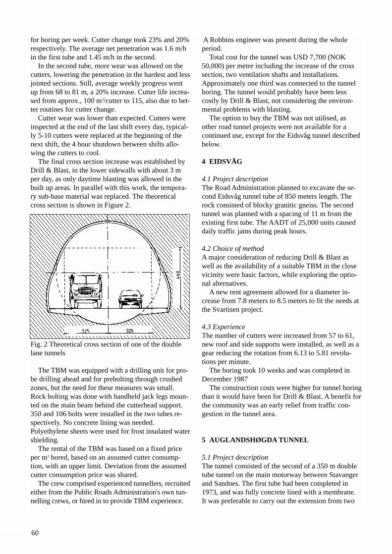
60
for boring per week. Cutter change took 23% and 20%respectively. The average net penetration was 1.6 m/hin the first tube and 1.45 m/h in the second.
In the second tube, more wear was allowed on thecutters, lowering the penetration in the hardest and lessjointed sections. Still, average weekly progress wentup from 68 to 81 m, a 20% increase. Cutter life increa-sed from approx., 100 m3/cutter to 115, also due to bet-ter routines for cutter change.
Cutter wear was lower than expected. Cutters wereinspected at the end of the last shift every day, typical-ly 5-10 cutters were replaced at the beginning of thenext shift, the 4 hour shutdown between shifts allo-wing the cutters to cool.
The final cross section increase was established byDrill & Blast, in the lower sidewalls with about 3 mper day, as only daytime blasting was allowed in thebuilt up areas. In parallel with this work, the tempora-ry sub-base material was replaced. The theoreticalcross section is shown in Figure 2.
Fig. 2 Theoretical cross section of one of the doublelane tunnels
The TBM was equipped with a drilling unit for pro-be drilling ahead and for prebolting through crushedzones, but the need for these measures was small.Rock bolting was done with handheld jack legs moun-ted on the main beam behind the cutterhead support.350 and 106 bolts were installed in the two tubes re-spectively. No concrete lining was needed.Polyethylene sheets were used for frost insulated watershielding.
The rental of the TBM was based on a fixed priceper m3 bored, based on an assumed cutter consump-tion, with an upper limit. Deviation from the assumedcutter consumption price was shared.
The crew comprised experienced tunnellers, recruitedeither from the Public Roads Administration's own tun-nelling crews, or hired in to provide TBM experience.
A Robbins engineer was present during the wholeperiod.
Total cost for the tunnel was USD 7,700 (NOK50,000) per metre including the increase of the crosssection, two ventilation shafts and installations.Approximately one third was connected to the tunnelboring. The tunnel would probably have been lesscostly by Drill & Blast, not considering the environ-mental problems with blasting.
The option to buy the TBM was not utilised, as other road tunnel projects were not available for acontinued use, except for the Eidsvåg tunnel described below.
4 EIDSVÅG
4.1 Project descriptionThe Road Administration planned to excavate the se-cond Eidsvåg tunnel tube of 850 meters length. Therock consisted of blocky granitic gneiss. The secondtunnel was planned with a spacing of 11 m from theexisting first tube. The AADT of 25,000 units causeddaily traffic jams during peak hours.
4.2 Choice of methodA major consideration of reducing Drill & Blast aswell as the availability of a suitable TBM in the closevicinity were basic factors, while exploring the optio-nal alternatives.
A new rent agreement allowed for a diameter in-crease from 7.8 meters to 8.5 meters to fit the needs atthe Svartisen project.
4.3 ExperienceThe number of cutters were increased from 57 to 61,new roof and side supports were installed, as well as agear reducing the rotation from 6.13 to 5.81 revolu-tions per minute.
The boring took 10 weeks and was completed inDecember 1987
The construction costs were higher for tunnel boringthan it would have been for Drill & Blast. A benefit forthe community was an early relief from traffic con-gestion in the tunnel area.
5 AUGLANDSHØGDA TUNNEL
5.1 Project descriptionThe tunnel consisted of the second of a 350 m doubletube tunnel on the main motorway between Stavangerand Sandnes. The first tube had been completed in1973, and was fully concrete lined with a membrane.It was preferable to carry out the extension from two
61
to four lanes without interruption to the 30,000 AADTtraffic, a situation similar to the Eidsvåg tunnel.
The tunnel cross section was 63 m2. The distancebetween the two tunnels was 11 m, to avoid damageby blasting to the lining in the first tube.
The rock was phyllite, with UCS 35-85 MPa, un-even foliation and thin quartz layers and lenses. Therock cover was down to 5 m near the portals, partlywith poor stability condition.
5.2 Choice of methodThe wish to try a method suitable for a non-circularcross section, triggered the co-operation for a trial pro-ject between Public Roads Administration and the con-tractor Selmer-Furuholmen A/S, who made available aWestfalia Lünen WAV 178, powered with 340 kW, 200kW for the cutterhead. The agreement was made for 50 m tunnel, to be exca-vated before the decision about further use would betaken.
5.3 ExperienceThe initial phase demonstrated the capabilities as follows: - Excavation capacity: 7.3 m3/h during cutting- Utilisation: 59%- Pick consumption: 0.85 pieces/m3
The cutting head was utilised to push the muck to-wards the loading belt.
Two types of picks were tried. The larger tungstencarbide inserts proved best, and it was important tochange broken cutters as early as possible, to avoidbreaking of neighbour picks and excessive wear on thesockets.
Several rock samples were taken showing UCS values ranging from 40 to 60 MPa, quartz content of38-51%, DRI of 49 and Bit Wear Index BWI of 31, indicating medium boreability. The rock mass had fewjoints besides the foliation.
The results were not satisfactory with respect tooverall performance, and the approach was changed inthe next phase. The inner part of the cross section wasblasted. 60 cm inside theoretical contour was left forroad header cutting.
The cutting improved due to the blasting cracks, butthe costs were still too high. Finally only 20 - 30 cmwere left for mechanical cutting. The remaining 300 mof tunnel was completed in this manner.
The total cost by this method was directly compar-able to Drill & Blast, approximately USD 3,000 (NOK19 000) per m, mainly because of a reduction of therock support by half. A prediction model for road-header cutting was developed using DRI, BWI andfrequency of jointing, as for TBM predictions.
The results demonstrated that roadheader cuttingwas not suitable in normal hard rock conditions, withmedium boreability parameters.
6 CONCLUSIONS
The experience from mechanical excavation of a totalof about 8 km road tunnels can be summarised as fol-lows:• Generally the results were positive with respect to
technical performance and progress for hard rock TBMs, including boring of massive, hard and abra-sive rocks.
• Problems in weak and water bearing zones were dif-ficult to handle due to the confined space. Valuable experience was gained regarding the efficient hand-ling of temporary rock support behind the cutter-head, and the utilisation of prepared equipment for probe drilling, pre-bolting and pre-grouting.
• The final product was agreeable, except for the dis-advantage of the cross section increase by blasting, creating irregular walls and delaying the completion.
• Available methods for cutting of non-circular tunnels were not feasible in normal hard rocksThe costs of a larger bored profile, big enough for
two traffic lanes, could at the time only be expected tobe competitive on a meter by meter basis under rockconditions favourable for tunnel boring. The possibili-ty of developing methods to adjust the circular TBMcross section, e.g. by using additional drums with disccutters to cut the lower corners, had been discussed. Itwas concluded that the large investment for a proto-type TBM and the technical risks involved did not justify such approach.
The later development of tunnel boring, notably theutilisation of cutters with much higher thrust capacity,has opened for boring of road tunnels with diametersup to approximately 10 m economically also in hardrocks. Ongoing development of integrated rock sup-port and water/frost insulation, to allow efficient com-pletion for traffic, will also make tunnel boring of roadtunnels more attractive.
62
Literature
Johansen, E. D. (1984): "Full face boring at Kobbelvand Glomfjord". Rock Blasting Conference, Oslo (InNorwegian)
Sellevold, N. H. & Øvstedal, E. (1984): "Boring inhard rock for road tunnels in Bergen. Economy andtechnical appraisal". Proc. Int. Symp. Low Cost RoadTunnels, Oslo
Johansen, E. D. (1985): "Another year with TBM ma-chines in Kobbelv and Holandsfjord". Rock BlastingConference, Oslo (In Norwegian)
Wallis, S. & Martin, D. (1985): "Cut and thrust atBergen. TBM drives twin motorway tunnel inNorway". Tunnels & Tunnelling, October 1985Hegrenæs, A. (1985): "Full face boring of road tunnel in Bergen". Rock Blasting Conference, Oslo (InNorwegian)
Hegrenæs, A. (1987): "Experiences from the Fløyfjelltunnel in Bergen. Fullface boring of the Eidsvåg tunnelII". Rock Blasting Conference, Oslo (In Norwegian)
Martinsen, J. (1987): "Bergen and beyond: WesternNorway's plan for a tunnel and a bridge network",Proc. RETC, New Orleans
Lone, T. K. & Arntsen, Ø. (1987): "Roadheader exca-vation of Auglandshøgda tunnel, Stavanger. Predictionmodel for part face cutting machines". Rock BlastingConference, Oslo (In Norwegian)
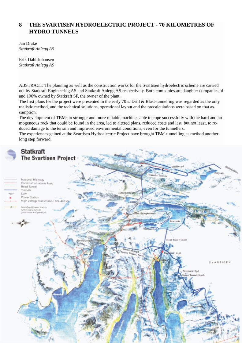
8 THE SVARTISEN HYDROELECTRIC PROJECT - 70 KILOMETRES OFHYDRO TUNNELS
Jan DrakeStatkraft Anlegg AS
Erik Dahl JohansenStatkraft Anlegg AS
ABSTRACT: The planning as well as the construction works for the Svartisen hydroelectric scheme are carriedout by Statkraft Engineering AS and Statkraft Anlegg AS respectively. Both companies are daughter companies ofand 100% owned by Statkraft SF, the owner of the plant.The first plans for the project were presented in the early 70’s. Drill & Blast-tunnelling was regarded as the onlyrealistic method, and the technical solutions, operational layout and the precalculations were based on that as-sumption.The development of TBMs to stronger and more reliable machines able to cope successfully with the hard and ho-mogeneous rock that could be found in the area, led to altered plans, reduced costs and last, but not least, to re-duced damage to the terrain and improved environmental conditions, even for the tunnellers.The experiences gained at the Svartisen Hydroelectric Project have brought TBM-tunnelling as method anotherlong step forward.
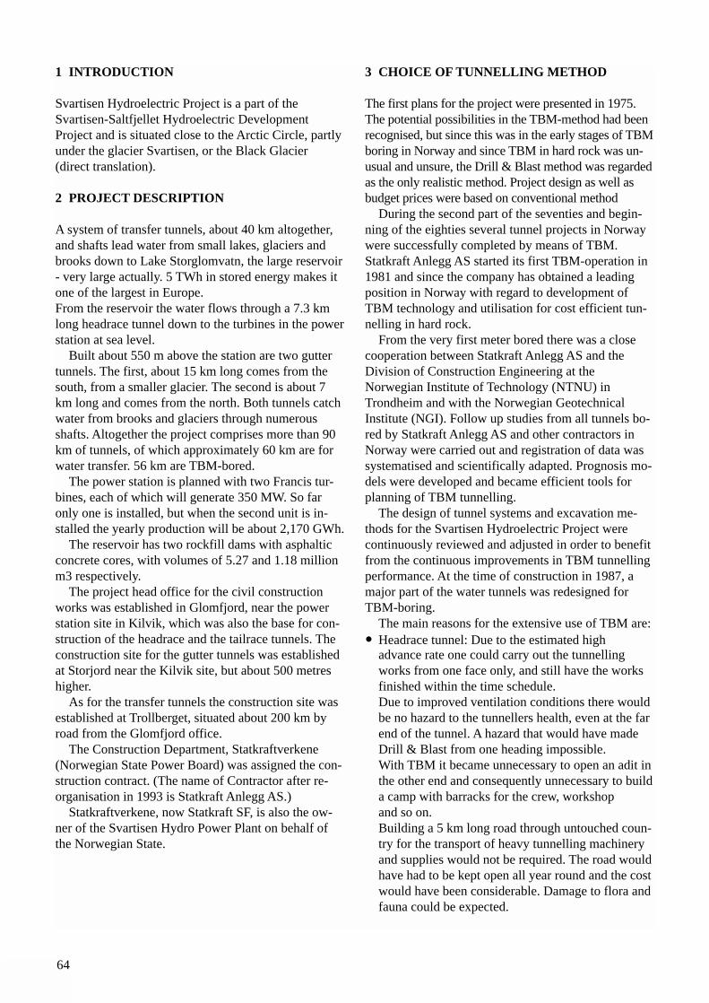
64
1 INTRODUCTION
Svartisen Hydroelectric Project is a part of theSvartisen-Saltfjellet Hydroelectric DevelopmentProject and is situated close to the Arctic Circle, partlyunder the glacier Svartisen, or the Black Glacier (direct translation).
2 PROJECT DESCRIPTION
A system of transfer tunnels, about 40 km altogether,and shafts lead water from small lakes, glaciers andbrooks down to Lake Storglomvatn, the large reservoir- very large actually. 5 TWh in stored energy makes itone of the largest in Europe.From the reservoir the water flows through a 7.3 kmlong headrace tunnel down to the turbines in the powerstation at sea level.
Built about 550 m above the station are two guttertunnels. The first, about 15 km long comes from thesouth, from a smaller glacier. The second is about 7km long and comes from the north. Both tunnels catchwater from brooks and glaciers through numerousshafts. Altogether the project comprises more than 90km of tunnels, of which approximately 60 km are forwater transfer. 56 km are TBM-bored.
The power station is planned with two Francis tur-bines, each of which will generate 350 MW. So faronly one is installed, but when the second unit is in-stalled the yearly production will be about 2,170 GWh.
The reservoir has two rockfill dams with asphalticconcrete cores, with volumes of 5.27 and 1.18 millionm3 respectively.
The project head office for the civil constructionworks was established in Glomfjord, near the powerstation site in Kilvik, which was also the base for con-struction of the headrace and the tailrace tunnels. Theconstruction site for the gutter tunnels was establishedat Storjord near the Kilvik site, but about 500 metreshigher.
As for the transfer tunnels the construction site wasestablished at Trollberget, situated about 200 km byroad from the Glomfjord office.
The Construction Department, Statkraftverkene(Norwegian State Power Board) was assigned the con-struction contract. (The name of Contractor after re-organisation in 1993 is Statkraft Anlegg AS.)
Statkraftverkene, now Statkraft SF, is also the ow-ner of the Svartisen Hydro Power Plant on behalf ofthe Norwegian State.
3 CHOICE OF TUNNELLING METHOD
The first plans for the project were presented in 1975.The potential possibilities in the TBM-method had beenrecognised, but since this was in the early stages of TBMboring in Norway and since TBM in hard rock was un-usual and unsure, the Drill & Blast method was regardedas the only realistic method. Project design as well asbudget prices were based on conventional method
During the second part of the seventies and begin-ning of the eighties several tunnel projects in Norwaywere successfully completed by means of TBM.Statkraft Anlegg AS started its first TBM-operation in1981 and since the company has obtained a leadingposition in Norway with regard to development ofTBM technology and utilisation for cost efficient tun-nelling in hard rock.
From the very first meter bored there was a closecooperation between Statkraft Anlegg AS and theDivision of Construction Engineering at theNorwegian Institute of Technology (NTNU) inTrondheim and with the Norwegian GeotechnicalInstitute (NGI). Follow up studies from all tunnels bo-red by Statkraft Anlegg AS and other contractors inNorway were carried out and registration of data wassystematised and scientifically adapted. Prognosis mo-dels were developed and became efficient tools forplanning of TBM tunnelling.
The design of tunnel systems and excavation me-thods for the Svartisen Hydroelectric Project werecontinuously reviewed and adjusted in order to benefitfrom the continuous improvements in TBM tunnellingperformance. At the time of construction in 1987, amajor part of the water tunnels was redesigned forTBM-boring.
The main reasons for the extensive use of TBM are:• Headrace tunnel: Due to the estimated high
advance rate one could carry out the tunnelling works from one face only, and still have the works finished within the time schedule.Due to improved ventilation conditions there would be no hazard to the tunnellers health, even at the far end of the tunnel. A hazard that would have made Drill & Blast from one heading impossible.With TBM it became unnecessary to open an adit inthe other end and consequently unnecessary to builda camp with barracks for the crew, workshop and so on.Building a 5 km long road through untouched coun-try for the transport of heavy tunnelling machinery and supplies would not be required. The road wouldhave had to be kept open all year round and the costwould have been considerable. Damage to flora and fauna could be expected.
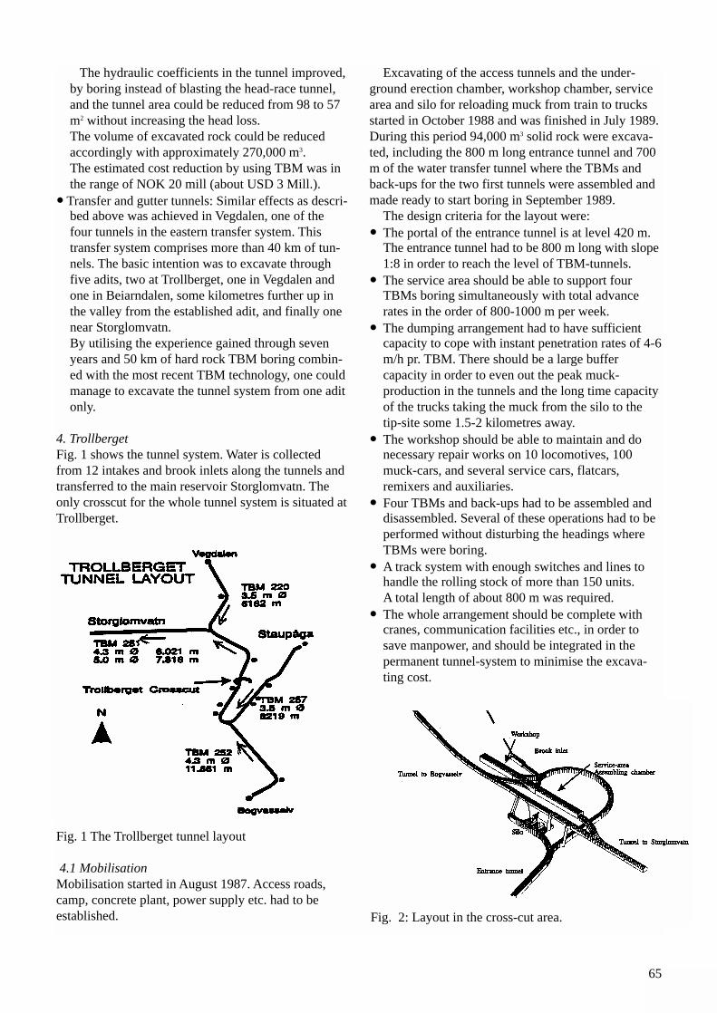
65
The hydraulic coefficients in the tunnel improved, by boring instead of blasting the head-race tunnel, and the tunnel area could be reduced from 98 to 57 m2 without increasing the head loss. The volume of excavated rock could be reduced accordingly with approximately 270,000 m3.The estimated cost reduction by using TBM was in the range of NOK 20 mill (about USD 3 Mill.).
• Transfer and gutter tunnels: Similar effects as descri-bed above was achieved in Vegdalen, one of the four tunnels in the eastern transfer system. This transfer system comprises more than 40 km of tun-nels. The basic intention was to excavate through five adits, two at Trollberget, one in Vegdalen and one in Beiarndalen, some kilometres further up in the valley from the established adit, and finally one near Storglomvatn.By utilising the experience gained through seven years and 50 km of hard rock TBM boring combin-ed with the most recent TBM technology, one could manage to excavate the tunnel system from one adit only.
4. TrollbergetFig. 1 shows the tunnel system. Water is collectedfrom 12 intakes and brook inlets along the tunnels andtransferred to the main reservoir Storglomvatn. Theonly crosscut for the whole tunnel system is situated atTrollberget.
Fig. 1 The Trollberget tunnel layout
4.1 MobilisationMobilisation started in August 1987. Access roads,camp, concrete plant, power supply etc. had to be established.
Excavating of the access tunnels and the under-ground erection chamber, workshop chamber, servicearea and silo for reloading muck from train to trucksstarted in October 1988 and was finished in July 1989.During this period 94,000 m3 solid rock were excava-ted, including the 800 m long entrance tunnel and 700m of the water transfer tunnel where the TBMs andback-ups for the two first tunnels were assembled andmade ready to start boring in September 1989.
The design criteria for the layout were:• The portal of the entrance tunnel is at level 420 m.
The entrance tunnel had to be 800 m long with slope1:8 in order to reach the level of TBM-tunnels.
• The service area should be able to support four TBMs boring simultaneously with total advance rates in the order of 800-1000 m per week.
• The dumping arrangement had to have sufficient capacity to cope with instant penetration rates of 4-6m/h pr. TBM. There should be a large buffer capacity in order to even out the peak muck-production in the tunnels and the long time capacity of the trucks taking the muck from the silo to the tip-site some 1.5-2 kilometres away.
• The workshop should be able to maintain and do necessary repair works on 10 locomotives, 100 muck-cars, and several service cars, flatcars, remixers and auxiliaries.
• Four TBMs and back-ups had to be assembled and disassembled. Several of these operations had to be performed without disturbing the headings where TBMs were boring.
• A track system with enough switches and lines to handle the rolling stock of more than 150 units. A total length of about 800 m was required.
• The whole arrangement should be complete with cranes, communication facilities etc., in order to save manpower, and should be integrated in the permanent tunnel-system to minimise the excava-ting cost.
Fig. 2: Layout in the cross-cut area.
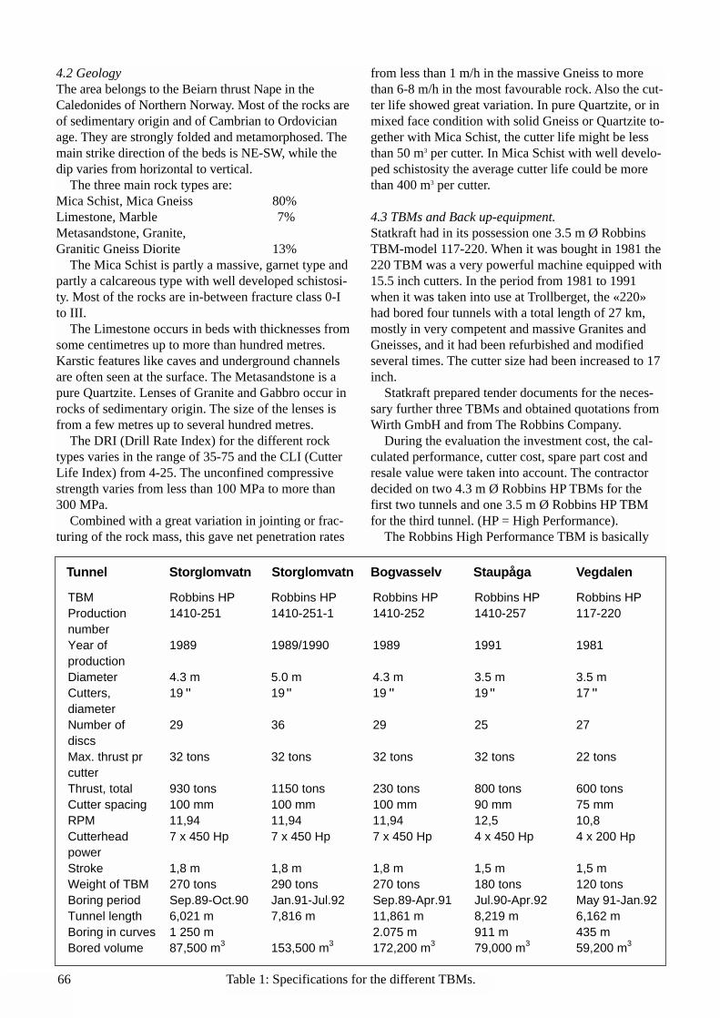
66
4.2 GeologyThe area belongs to the Beiarn thrust Nape in theCaledonides of Northern Norway. Most of the rocks areof sedimentary origin and of Cambrian to Ordovicianage. They are strongly folded and metamorphosed. Themain strike direction of the beds is NE-SW, while thedip varies from horizontal to vertical.
The three main rock types are:Mica Schist, Mica Gneiss 80%Limestone, Marble 7%Metasandstone, Granite,Granitic Gneiss Diorite 13%
The Mica Schist is partly a massive, garnet type andpartly a calcareous type with well developed schistosi-ty. Most of the rocks are in-between fracture class 0-Ito III.
The Limestone occurs in beds with thicknesses fromsome centimetres up to more than hundred metres.Karstic features like caves and underground channelsare often seen at the surface. The Metasandstone is apure Quartzite. Lenses of Granite and Gabbro occur inrocks of sedimentary origin. The size of the lenses isfrom a few metres up to several hundred metres.
The DRI (Drill Rate Index) for the different rock types varies in the range of 35-75 and the CLI (CutterLife Index) from 4-25. The unconfined compressivestrength varies from less than 100 MPa to more than300 MPa.
Combined with a great variation in jointing or frac-turing of the rock mass, this gave net penetration rates
from less than 1 m/h in the massive Gneiss to more than 6-8 m/h in the most favourable rock. Also the cut-ter life showed great variation. In pure Quartzite, or inmixed face condition with solid Gneiss or Quartzite to-gether with Mica Schist, the cutter life might be lessthan 50 m3 per cutter. In Mica Schist with well develo-ped schistosity the average cutter life could be morethan 400 m3 per cutter.
4.3 TBMs and Back up-equipment.Statkraft had in its possession one 3.5 m Ø RobbinsTBM-model 117-220. When it was bought in 1981 the220 TBM was a very powerful machine equipped with15.5 inch cutters. In the period from 1981 to 1991when it was taken into use at Trollberget, the «220»had bored four tunnels with a total length of 27 km,mostly in very competent and massive Granites andGneisses, and it had been refurbished and modified several times. The cutter size had been increased to 17inch.
Statkraft prepared tender documents for the neces-sary further three TBMs and obtained quotations fromWirth GmbH and from The Robbins Company.
During the evaluation the investment cost, the cal-culated performance, cutter cost, spare part cost andresale value were taken into account. The contractordecided on two 4.3 m Ø Robbins HP TBMs for thefirst two tunnels and one 3.5 m Ø Robbins HP TBMfor the third tunnel. (HP = High Performance).
The Robbins High Performance TBM is basically
TBM Robbins HP Robbins HP Robbins HP Robbins HP Robbins HPProductionnumber
1410-251 1410-251-1 1410-252 1410-257 117-220
Year ofproduction
1989 1989/1990 1989 1991 1981
Diameter 4.3 m 5.0 m 4.3 m 3.5 m 3.5 mCutters,diameter
19 19 19 19 17
Number ofdiscs
29 36 29 25 27
Max. thrust prcutter
32 tons 32 tons 32 tons 32 tons 22 tons
Thrust, total 930 tons 1150 tons 230 tons 800 tons 600 tonsCutter spacing 100 mm 100 mm 100 mm 90 mm 75 mmRPM 11,94 11,94 11,94 12,5 10,8Cutterheadpower
7 x 450 Hp 7 x 450 Hp 7 x 450 Hp 4 x 450 Hp 4 x 200 Hp
Stroke 1,8 m 1,8 m 1,8 m 1,5 m 1,5 mWeight of TBM 270 tons 290 tons 270 tons 180 tons 120 tonsBoring period Sep.89-Oct.90 Jan.91-Jul.92 Sep.89-Apr.91 Jul.90-Apr.92 May 91-Jan.92Tunnel length 6,021 m 7,816 m 11,861 m 8,219 m 6,162 mBoring in curves 1 250 m 2.075 m 911 m 435 mBored volume 87,500 m3 153,500 m3 172,200 m3 79,000 m3 59,200 m3
" " " " "
Table 1: Specifications for the different TBMs.
Tunnel Storglomvatn Storglomvatn Bogvasselv Staupåga Vegdalen
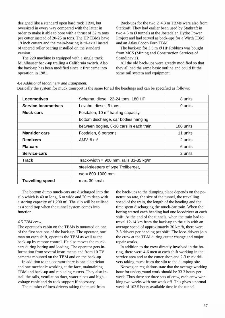
67
Locomotives Schøma, diesel, 22-24 tons, 180 HP 8 units
Service-locomotives Levahn, diesel, 9 tons 9 units
Muck-cars Fosdalen, 10 m3 hauling capacity,
bottom discharge, car bodies hanging
between bogies, 8-10 cars in each train. 100 units
Manrider cars Fosdalen, 6 persons 11 units
Remixers AMV, 6 m3 2 units
Flatcars 6 units
Service-cars 2 units
Track Track-width = 900 mm, rails 33-35 kg/m
steel-sleepers of type Trollberget,
c/c = 800-1000 mm
Travelling speed max. 30 km/h
The bottom dump muck-cars are discharged into thesilo which is 40 m long, 6 m wide and 20 m deep witha storing capacity of 1,200 m3. The silo will be utilisedas a sand trap when the tunnel system comes into function.
4.5 TBM crew.The operator’s cabin on the TBMs is mounted on oneof the first sections of the back-up. The operator, oneman on each shift, operates the TBM as well as theback-up by remote control. He also moves the muck-cars during boring and loading. The operator gets in-formation from several instruments and from 10 TVcameras mounted on the TBM and on the back-up.
In addition to the operator there is one electricianand one mechanic working at the face, maintainingTBM and back-up and replacing cutters. They also in-stall the rails, ventilation duct, water pipes and high-voltage cable and do rock support if necessary.
The number of loco-drivers taking the muck from
the back-ups to the dumping place depends on the pe-netration rate, the size of the tunnel, the travelling speed of the train, the length of the heading and thetime spent discharging the muck-car train. When theboring started each heading had one locodriver at eachshift. At the end of the tunnels, when the train had totravel 12-14 km from the back-up to the silo with anaverage speed of approximately 30 km/h, there were 2-3 drivers per heading per shift. The loco-drivers jointhe crew at the TBM during cutter change and majorrepair works.
In addition to the crew directly involved in the bo-ring, there were 4-6 men at each shift working in theservice area and at the cutter shop and 2-3 truck dri-vers taking muck from the silo to the dumping site.
Norwegian regulations state that the average workinghour for underground work should be 33.3 hours perweek. Thus there are three sets of crew, each crew wor-king two weeks with one week off. This gives a normalweek of 102.5 hours available time in the tunnel.
designed like a standard open hard rock TBM, butoversized in every way compared with the latter in order to make it able to bore with a thrust of 32 m tonsper cutter instead of 20-25 m tons. The HP TBMs have19 inch cutters and the main-bearing is tri-axial instadof tapered roller bearing installed on the standard version.
The 220 machine is equipped with a single trackMuhlhauser back-up trailing a California switch. Alsothe back-up has been modified since it first came intooperation in 1981.
Back-ups for the two Ø 4.3 m TBMs were also fromStatkraft. They had earlier been used by Statkraft intwo 4.5 m Ø tunnels at the Jostedalen Hydro PowerProject and had served as back-ups for a Wirth TBMand an Atlas Copco Foro TBM.
The back-up for 3.5 m Ø HP Robbins was boughtfrom MCS (Mining and Construction Services ofScandinavia).
All the old back-ups were greatly modified so thatthey all had the same basic outline and could fit thesame rail system and equipment.
4.4 Additional Machinery and Equipment.Basically the system for muck transport is the same for all the headings and can be specified as follows:
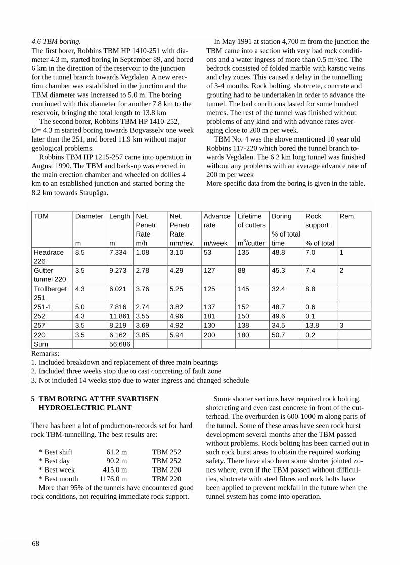
4.6 TBM boring.The first borer, Robbins TBM HP 1410-251 with dia-meter 4.3 m, started boring in September 89, and bored6 km in the direction of the reservoir to the junctionfor the tunnel branch towards Vegdalen. A new erec-tion chamber was established in the junction and theTBM diameter was increased to 5.0 m. The boringcontinued with this diameter for another 7.8 km to thereservoir, bringing the total length to 13.8 km
The second borer, Robbins TBM HP 1410-252, Ø= 4.3 m started boring towards Bogvasselv one weeklater than the 251, and bored 11.9 km without majorgeological problems.
Robbins TBM HP 1215-257 came into operation inAugust 1990. The TBM and back-up was erected inthe main erection chamber and wheeled on dollies 4km to an established junction and started boring the 8.2 km towards Staupåga.
In May 1991 at station 4,700 m from the junction theTBM came into a section with very bad rock conditi-ons and a water ingress of more than 0.5 m3/sec. Thebedrock consisted of folded marble with karstic veinsand clay zones. This caused a delay in the tunnellingof 3-4 months. Rock bolting, shotcrete, concrete andgrouting had to be undertaken in order to advance thetunnel. The bad conditions lasted for some hundredmetres. The rest of the tunnel was finished withoutproblems of any kind and with advance rates aver-aging close to 200 m per week.
TBM No. 4 was the above mentioned 10 year oldRobbins 117-220 which bored the tunnel branch to-wards Vegdalen. The 6.2 km long tunnel was finishedwithout any problems with an average advance rate of200 m per weekMore specific data from the boring is given in the table.
68
TBM Diameter
m
Length
m
Net.Penetr.Ratem/h
Net.Penetr.Ratemm/rev.
Advancerate
m/week
Lifetimeof cutters
m3/cutter
Boring
% of totaltime
Rocksupport
% of total
Rem.
Headrace226
8.5 7.334 1.08 3.10 53 135 48.8 7.0 1
Guttertunnel 220
3.5 9.273 2.78 4.29 127 88 45.3 7.4 2
Trollberget251
4.3 6.021 3.76 5.25 125 145 32.4 8.8
251-1 5.0 7.816 2.74 3.82 137 152 48.7 0.6252 4.3 11.861 3.55 4.96 181 150 49.6 0.1257 3.5 8.219 3.69 4.92 130 138 34.5 13.8 3220 3.5 6.162 3.85 5.94 200 180 50.7 0.2Sum 56,686
Remarks:1. Included breakdown and replacement of three main bearings2. Included three weeks stop due to cast concreting of fault zone3. Not included 14 weeks stop due to water ingress and changed schedule
5 TBM BORING AT THE SVARTISEN HYDROELECTRIC PLANT
There has been a lot of production-records set for hardrock TBM-tunnelling. The best results are:
* Best shift 61.2 m TBM 252* Best day 90.2 m TBM 252* Best week 415.0 m TBM 220* Best month 1176.0 m TBM 220More than 95% of the tunnels have encountered good
rock conditions, not requiring immediate rock support.
Some shorter sections have required rock bolting,shotcreting and even cast concrete in front of the cut-terhead. The overburden is 600-1000 m along parts ofthe tunnel. Some of these areas have seen rock burstdevelopment several months after the TBM passedwithout problems. Rock bolting has been carried out insuch rock burst areas to obtain the required workingsafety. There have also been some shorter jointed zo-nes where, even if the TBM passed without difficul-ties, shotcrete with steel fibres and rock bolts havebeen applied to prevent rockfall in the future when thetunnel system has come into operation.
69
4.7 ConclusionsStatkraft had already TBM-bored more than 50 km inhard rock when the boring at Svartisen started, and hadgained experience and know-how on geology, machineproperties, the correlation between the two, and per-haps the most important of all, how to achieve tunnelmetres in practice.
Even so we took a calculated risk when we startedboring at Trollberget with a new generation of TBMsand what we considered as a rather optimistic lay-out. The boring at Trollberget has given a lot of new infor-mation and experience as input to further developmentin hard rock boring.
The High Performance TBM is a very strong machi-ne. The main structure, the main bearing and the tor-que capacity allow high thrust required to achieve highpenetration rates in hard rock. Thus the potential in theTBM itself is very great. However, our experience isthat the cutters are unable to meet the rated load unlessthe conditions are almost ideal. No construction isstronger than the weakest link, which in our case andfor the time being, is the cutter. There is still a greatpotential for improvement of cutters and cutter confi-guration on the cutterhead to obtain better cutter lifeand to raise the cutter load and thus increase penetra-tion rates and reduce down-time due to cutter changing.
TBM-tunnelling is like running a factory. Machinery,equipment, crew and management are joined in oneunit, which has the goal of doing the job in an optimal
way. Very often too much attention is paid to the TBMas the main commodity in the process while the rest ofthe system gets less attention, and the result being aTBM without sufficient support to be able to utilise theTBM-capacity. The upfront planning and the quality ofthe crew and the management are as important as theTBM.
As a government-owned company, Statkraft has al-ways felt the obligation to play an active part in testingnew machinery and methods, and in accordance withgive-and get traditions in the field, to share the experi-ences openly. Thus, the experiences gained atTrollberget has brought hard rock boring one step for-ward and has already been utilised in other Norwegianprojects, proving useful in the struggle for higher tun-nel production and improved economy.

70
71
1 INTRODUCTION
Norwegian tunnelling experience includes a signifi-cant number of tunnels with high rock stresses. Theproblems are typically related to rock spalling due toanisotropic stresses below steep valley sides. This maybe encountered during excavation of hydropowerplants and tunnels in areas with dramatic topography,or in road tunnels along or between fjords under highcover. The experiences from deep level mining withthe need to minimise pillar size have also brought sig-nificant contributions to the understanding of the rockmechanics involved.
The tunnelling community in Norway has a tho-rough understanding of the phenomena of high rockstresses. This includes the precautions during planningand the practical measures during construction tomaintain safety and progress when rock spalling is en-countered. Methods for predictions of rock stress pro-blems had been established on the basis of experiencesin blasted tunnels, Russenes (1974). Methods for rockstress measurements were well developed and fre-quently applied when problems were foreseen or en-countered.
The rapid development and application of tunnelboring resulted in the need to handle rock stress pro-blems also in bored tunnels. The experience should beof interest to anyone planning TBM projects wheresuch problems may be encountered.
2 SILDVIK
The first TBM project in Norway to meet rock stressproblems was the inclined shaft at SildvikHydropower Project. The headrace pressure shaft hadan inclination of 45 degrees, 2.5 m diameter andlength of 760 m. The rock was a quartz-biotite schist.The experiences are summarised below based onSkjeggedal (1980 and 1981) and Dahle & Heltzen(1981).
Problems with intense spalling were experienced inthe access tunnel and in the power station area. Thismade it necessary to perform extensive rock supportby rock bolting and sprayed concrete. In the accesstunnel, rock stress measurements showed the majorprincipal stress of approx. 21 MPa, the intermediate of18 MPa, both close to horizontal. The minor principalstress was 8 MPa. The rock cover was about 400 munder the steeply sloping valley side. The rock had anuniaxial compressive strength of 150 MPa.
From this rock stress problems were expected, espe-cially in the lower parts of the shaft. From the orienta-tion of the major principal stress in relation to theshaft, it was assumed that the spalling would occur inthe area between the roof and the face, giving pro-blems with work safety during cutter change. It wasforeseen that spalling in the left side of the roof andthe right side of the invert could result in loss of sup-port for the TBM gripping pads.
Although the configuration of the Wirth TBM leftvery little space for activities immediately behind thecutterhead, the contractor A/S Høyer-Ellefsen was wellprepared. From the reports the following can be noted:
9 ROCK STRESS PROBLEMS IN BORED TUNNELS
Arne MyrvangThe Norwegian University of Science and Technology, Trondheim
Olav Torgeir BlindheimO. T. Blindheim AS, Trondheim
Erik Dahl JohansenStatkraft Anlegg as, Oslo
ABSTRACT: The paper summarises the experience of rock stress phenomena in TBM tunnels in Norway. Theserange from serious problems with intense rock spalling in hard and massive rock, causing significant safety ha-zards and delays in work progress, to occurrences of mild buckling of schistose rock, or long term slabbing du-ring operation of unlined water tunnels.
Possibilities exist for predictions of such problems, although this is not discussed in detail in this paper. The needto be prepared is highlighted. Especially, it is important to be able to perform rock bolting efficiently immediatelybehind the cutter head in order to maintain work safety and firm gripping for continued boring.
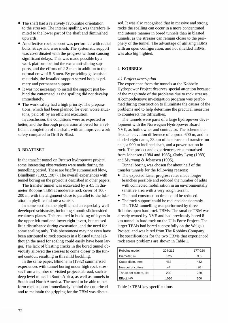
72
• The shaft had a relatively favourable orientation to the stresses. The intense spalling was therefore li-mited to the lower part of the shaft and diminished upwards.
• An effective rock support was performed with radialbolts, straps and wire mesh. The systematic support was co-ordinated with the progress without causing significant delays. This was made possible by a work platform behind the extra anti-sliding sup-ports, and the efforts of 2-3 men in addition to the normal crew of 5-6 men. By providing galvanised materials, the installed support served both as pri-mary and permanent support.
• It was not necessary to install the support just be-hind the cutterhead, as the spalling did not develop immediately.
• The work safety had a high priority. The prepara-tions, which had been planned for even worse situa-tons, paid off by an efficient execution.In conclusion, the conditions were as expected or
better, and the thorough preparation allowed for an ef-ficient completion of the shaft, with an improved worksafety compared to Drill & Blast.
3 BRATTSET
In the transfer tunnel on Brattset hydropower project,some interesting observations were made during thetunnelling period. These are briefly summarised blow,Blindheim (1982, 1987). The overall experiences withtunnel boring on the project is described in other papers.
The transfer tunnel was excavated by a 4.5 m dia-meter Robbins TBM at moderate rock cover of 100-200 m, with the alignment close to parallel to the foli-ation in phyllite and mica schists.
In some sections the phyllite had an especially welldeveloped schistosity, including smooth slickensidedweakness planes. This resulted in buckling of layers inthe upper left roof and lower right invert, but causedlittle disturbance during excavation, and the need forsome scaling only. This phenomena may not even havebeen attributed to rock stresses in a blasted tunnel al-though the need for scaling could easily have been lar-ger. The lack of blasting cracks in the bored tunnel ob-viously allowed the stresses to come closer to the tun-nel contour, resulting in this mild buckling.
In the same paper, Blindheim (1982) summarisedexperiences with tunnel boring under high rock stres-ses from a number of visited projects abroad, such asdeep level mines in South Africa, as well as tunnels inSouth and North America. The need to be able to per-form rock support immediately behind the cutterheadand to maintain the gripping for the TBM was discus-
sed. It was also recognised that in massive and strongrocks the spalling can occur in a more concentratedand intense manner in bored tunnels than in blastedtunnels, as the stresses can remain closer to the peri-phery of the tunnel. The advantage of utilising TBMswith an open configuration, and not shielded TBMs,was also highlighted.
4 KOBBELV
4.1 Project descriptionThe experience from the tunnels at the KobbelvHydropower Project deserves special attention becauseof the magnitude of the problems due to rock stresses.A comprehensive investigation program was perfor-med during construction to illuminate the causes of theproblems and to help determine the practical measuresto counteract the difficulties.
The tunnels were parts of a large hydropower deve-lopment with the Norwegian Hydropower Board,NVE, as both owner and contractor. The scheme uti-lised an elevation difference of approx. 600 m, and in-cluded eight dams, 33 km of headrace and transfer tun-nels, a 900 m inclined shaft, and a power station inrock. The project and experiences are summarisedfrom Johansen (1984 and 1985), Østby Lyng (1989)and Myrvang & Johansen (1995).
Tunnel boring was chosen for about half of thetransfer tunnels for the following reasons:• The expected faster progress rates made longer
branches possible and reduced the number of adits with connected mobilisation in an environmentally sensitive area with a very rough terrain.
• The total construction time could be reduced.• The rock support could be reduced considerably.
The TBM tunnelling was performed by threeRobbins open hard rock TBMs. The smaller TBM wasalready owned by NVE and had previously bored 8km tunnel in hard rock on the Ulla Førre Project. Thelarger TBMs had bored successfully on the WalgauProject, and was hired from The Robbins Company.The specifications for the two TBMs that experiencedrock stress problems are shown in Table 1.
Table 1: TBM key specifications
Robbins model 204-215 177-220
Diameter, m 6.25 3.5
Cutter diam., mm 432 432
Number of cutters 44 26
Thrust per cutters, kN 230 220
Effect, kW 1050 600
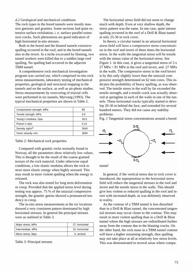
4.2 Geological and mechanical conditionsThe rock types in the bored tunnels were mostly mas-sive gneisses and granites. Some sections had quite ex-tensive surface exfoliation, i. e. surface parallel exten-sion cracks. Such phenomena are good indicators ofhigh horizontal in-situ stresses.
Both in the bored and the blasted tunnels extensivespalling occurred in the roof, and in the bored tunnelsalso in the invert. In a niche excavated by blasting, twotunnel workers were killed due to a sudden large roofspalling. No spalling had occurred in the adjacentTBM tunnel.
A comprehensive rock mechanical investigationprogram was carried out, which comprised in-situ rockstress measurements, laboratory testing of mechanicalproperties, geological and structural mapping in thetunnels and on the surface, as well as air-photo studies.Stress measurements by overcoring of triaxial cellswere performed in six tunnels, Myrvang (1993). Thetypical mechanical properties are shown in Table 2.
Table 2: Mechanical rock properties
Compared with granitic rocks normally found inNorway, all the parameters show relatively low values.This is thought to be the result of the coarse grainedtexture of the rock material. Under otherwise equalconditions, a low elastic modulus allows the rock tostore more elastic energy when highly stressed. Thismay result in more violent spalling when the energy isreleased.
The rock was also tested for long term deformationor creep. Provided that the applied stress level duringtesting was approx. 75 % of the uniaxial compressivestrength, the granitic gneiss showed a pronounced ten-dency to creep.
The in-situ stress measurements at the six locationsshowed a very consistent pattern dominated by highhorizontal stresses. In general the principal stresseswere as outlined in Table 3.
Table 3: Principal stresses
The horizontal stress field did not seem to changemuch with depth. Even at very shallow depth, thestress pattern was the same. In one case, quite intensespalling occurred in the roof of a Drill & Blast tunnelat only 25-30 m rock cover.
In theory, a circular tunnel in an uniaxial horizontalstress field will have a compressive stress concentrati-on in the roof and invert of three times the horizontalstress. In the walls the tangential stress will be tensilewith the minus value of the horizontal stress. SeeFigure 1. In this case, it gives a tangential stress of 3 x27 MPa = 81 MPa in the roof and invert, and -27 MPain the walls. The compressive stress in the roof/invertis by this only slightly lower than the uniaxial com-pressive strength determined on 62 mm cores. This in-dicates the probability of heavy spalling, as was obser-ved. The tensile stress in the wall by far exceeded thetensile strength, and a tensile crack was actually obser-ved at springline in each of the walls in one of the tun-nels. These horizontal cracks typically started to deve-lop 20-30 m behind the face, and extended for severalhundred meters. They did not cause any stability problems.Fig. 1 Tangential stress concentrations around a bored
tunnel
In general, if the vertical stress due to rock cover isintroduced, the superposition to the horizontal stressfield will reduce the tangential stresses in the roof andinvert and the tensile stress in the walls. This shouldgive less violent or reduced spalling in the roof and in-vert with increased depth, as was definitely observedin reality.
As the contour of a TBM tunnel is less disturbedthan in a Drill & Blast tunnel, the concentrated tangen-tial stresses may occur closer to the contour. This mayresult in more violent spalling than in a Drill & Blasttunnel where the high stresses are redistributed furtheraway from the contour due to the blasting cracks. Onthe other hand, the rock mass in a TBM tunnel contourwill have a higher remaining strength, thus spallingmay not take place at all at relatively low stress levels.This was demonstrated in several areas where compa-
Compressive strength, MPa 89
Tensile strength, MPa 9.5
Young´s modulus, Gpa 18.5
Poison´s ratio 0.13
Density, kg/m3 2640
Sonic velocity, m/s 3000
73
Major stress, MPa 27, horizontal
Intermediate, MPa 15, horizontal
Minor stress, Mpa 5, vertical
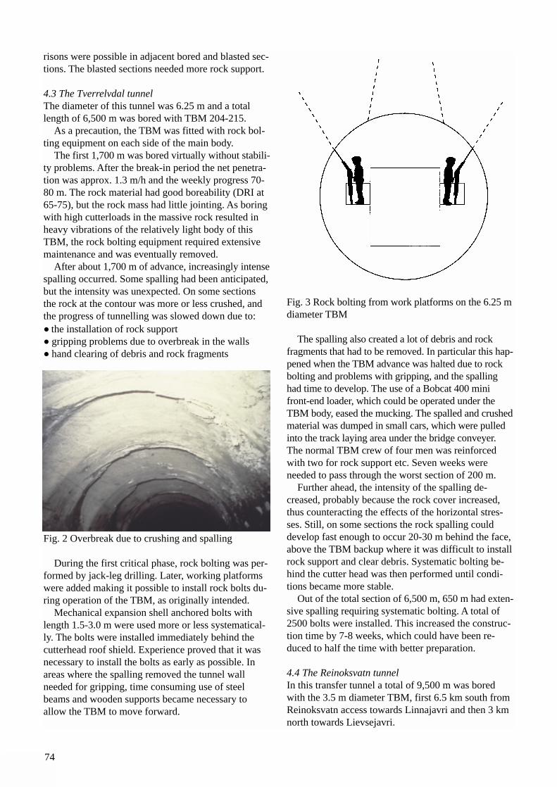
74
risons were possible in adjacent bored and blasted sec-tions. The blasted sections needed more rock support.
4.3 The Tverrelvdal tunnelThe diameter of this tunnel was 6.25 m and a totallength of 6,500 m was bored with TBM 204-215.
As a precaution, the TBM was fitted with rock bol-ting equipment on each side of the main body.
The first 1,700 m was bored virtually without stabili-ty problems. After the break-in period the net penetra-tion was approx. 1.3 m/h and the weekly progress 70-80 m. The rock material had good boreability (DRI at65-75), but the rock mass had little jointing. As boringwith high cutterloads in the massive rock resulted inheavy vibrations of the relatively light body of thisTBM, the rock bolting equipment required extensivemaintenance and was eventually removed.
After about 1,700 m of advance, increasingly intensespalling occurred. Some spalling had been anticipated,but the intensity was unexpected. On some sectionsthe rock at the contour was more or less crushed, andthe progress of tunnelling was slowed down due to:• the installation of rock support• gripping problems due to overbreak in the walls• hand clearing of debris and rock fragments
Fig. 2 Overbreak due to crushing and spalling
During the first critical phase, rock bolting was per-formed by jack-leg drilling. Later, working platformswere added making it possible to install rock bolts du-ring operation of the TBM, as originally intended.
Mechanical expansion shell anchored bolts withlength 1.5-3.0 m were used more or less systematical-ly. The bolts were installed immediately behind thecutterhead roof shield. Experience proved that it wasnecessary to install the bolts as early as possible. Inareas where the spalling removed the tunnel wall needed for gripping, time consuming use of steel beams and wooden supports became necessary to allow the TBM to move forward.
Fig. 3 Rock bolting from work platforms on the 6.25 mdiameter TBM
The spalling also created a lot of debris and rockfragments that had to be removed. In particular this hap-pened when the TBM advance was halted due to rockbolting and problems with gripping, and the spallinghad time to develop. The use of a Bobcat 400 minifront-end loader, which could be operated under theTBM body, eased the mucking. The spalled and crushedmaterial was dumped in small cars, which were pulledinto the track laying area under the bridge conveyer.The normal TBM crew of four men was reinforcedwith two for rock support etc. Seven weeks were needed to pass through the worst section of 200 m.
Further ahead, the intensity of the spalling de-creased, probably because the rock cover increased,thus counteracting the effects of the horizontal stres-ses. Still, on some sections the rock spalling could develop fast enough to occur 20-30 m behind the face,above the TBM backup where it was difficult to installrock support and clear debris. Systematic bolting be-hind the cutter head was then performed until condi-tions became more stable.
Out of the total section of 6,500 m, 650 m had exten-sive spalling requiring systematic bolting. A total of2500 bolts were installed. This increased the construc-tion time by 7-8 weeks, which could have been re-duced to half the time with better preparation.
4.4 The Reinoksvatn tunnelIn this transfer tunnel a total of 9,500 m was boredwith the 3.5 m diameter TBM, first 6.5 km south fromReinoksvatn access towards Linnajavri and then 3 kmnorth towards Lievsejavri.
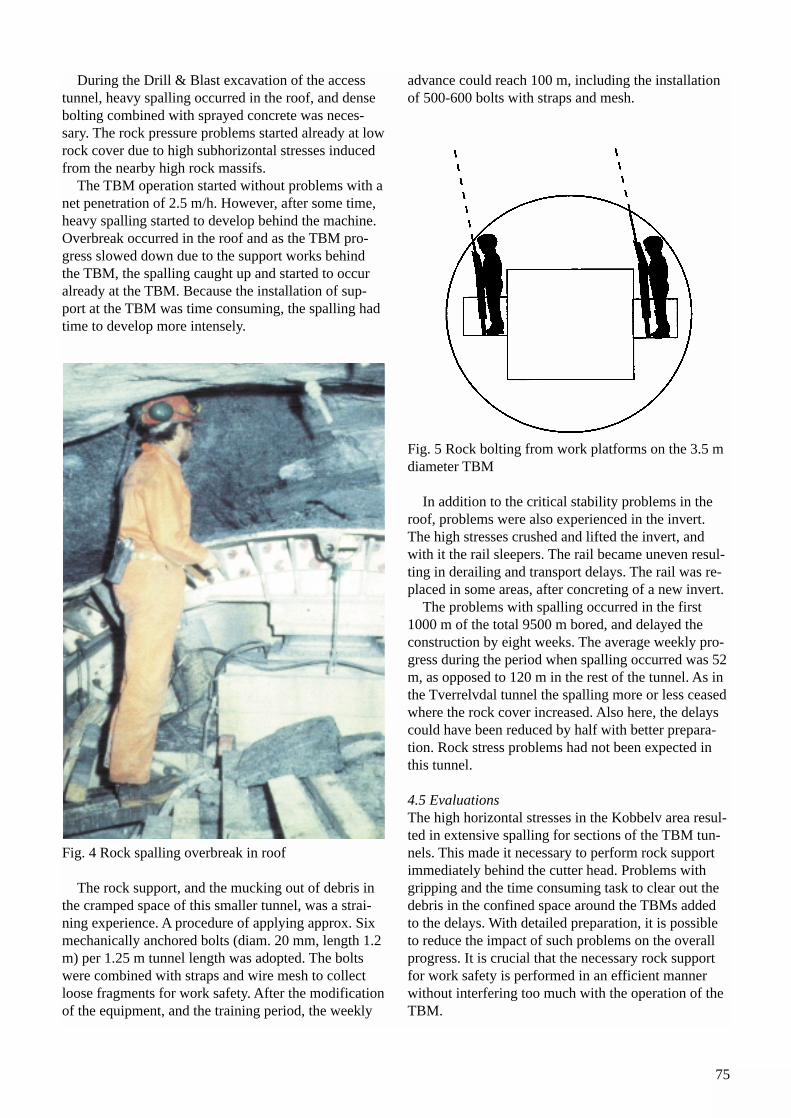
75
During the Drill & Blast excavation of the accesstunnel, heavy spalling occurred in the roof, and densebolting combined with sprayed concrete was neces-sary. The rock pressure problems started already at lowrock cover due to high subhorizontal stresses inducedfrom the nearby high rock massifs.
The TBM operation started without problems with anet penetration of 2.5 m/h. However, after some time,heavy spalling started to develop behind the machine.Overbreak occurred in the roof and as the TBM pro-gress slowed down due to the support works behindthe TBM, the spalling caught up and started to occuralready at the TBM. Because the installation of sup-port at the TBM was time consuming, the spalling hadtime to develop more intensely.
Fig. 4 Rock spalling overbreak in roof
The rock support, and the mucking out of debris inthe cramped space of this smaller tunnel, was a strai-ning experience. A procedure of applying approx. Sixmechanically anchored bolts (diam. 20 mm, length 1.2m) per 1.25 m tunnel length was adopted. The boltswere combined with straps and wire mesh to collectloose fragments for work safety. After the modificationof the equipment, and the training period, the weekly
advance could reach 100 m, including the installationof 500-600 bolts with straps and mesh.
Fig. 5 Rock bolting from work platforms on the 3.5 mdiameter TBM
In addition to the critical stability problems in theroof, problems were also experienced in the invert.The high stresses crushed and lifted the invert, andwith it the rail sleepers. The rail became uneven resul-ting in derailing and transport delays. The rail was re-placed in some areas, after concreting of a new invert.
The problems with spalling occurred in the first1000 m of the total 9500 m bored, and delayed theconstruction by eight weeks. The average weekly pro-gress during the period when spalling occurred was 52m, as opposed to 120 m in the rest of the tunnel. As inthe Tverrelvdal tunnel the spalling more or less ceasedwhere the rock cover increased. Also here, the delayscould have been reduced by half with better prepara-tion. Rock stress problems had not been expected inthis tunnel.
4.5 EvaluationsThe high horizontal stresses in the Kobbelv area resul-ted in extensive spalling for sections of the TBM tun-nels. This made it necessary to perform rock supportimmediately behind the cutter head. Problems withgripping and the time consuming task to clear out thedebris in the confined space around the TBMs addedto the delays. With detailed preparation, it is possibleto reduce the impact of such problems on the overallprogress. It is crucial that the necessary rock supportfor work safety is performed in an efficient mannerwithout interfering too much with the operation of theTBM.
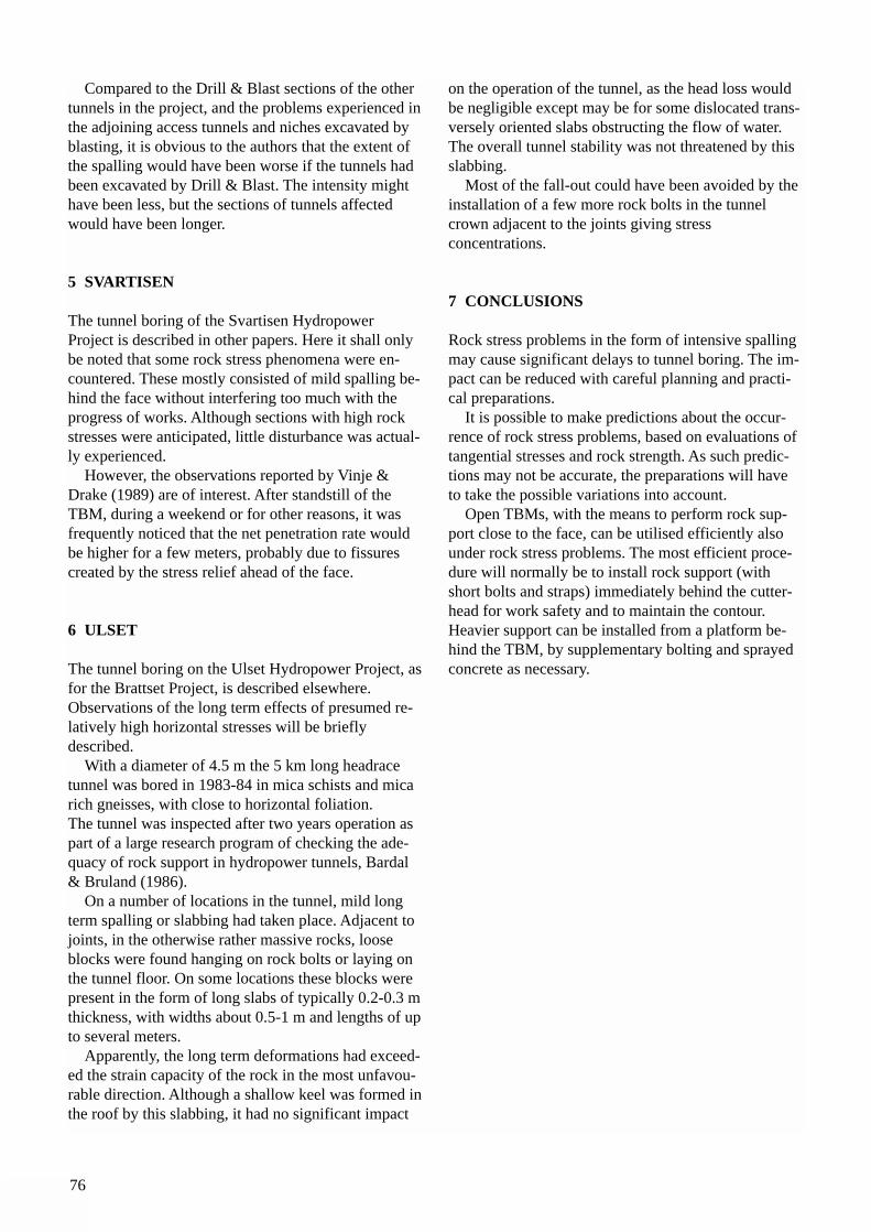
76
Compared to the Drill & Blast sections of the othertunnels in the project, and the problems experienced inthe adjoining access tunnels and niches excavated byblasting, it is obvious to the authors that the extent ofthe spalling would have been worse if the tunnels hadbeen excavated by Drill & Blast. The intensity mighthave been less, but the sections of tunnels affectedwould have been longer.
5 SVARTISEN
The tunnel boring of the Svartisen HydropowerProject is described in other papers. Here it shall onlybe noted that some rock stress phenomena were en-countered. These mostly consisted of mild spalling be-hind the face without interfering too much with theprogress of works. Although sections with high rockstresses were anticipated, little disturbance was actual-ly experienced.
However, the observations reported by Vinje &Drake (1989) are of interest. After standstill of theTBM, during a weekend or for other reasons, it wasfrequently noticed that the net penetration rate wouldbe higher for a few meters, probably due to fissurescreated by the stress relief ahead of the face.
6 ULSET
The tunnel boring on the Ulset Hydropower Project, asfor the Brattset Project, is described elsewhere.Observations of the long term effects of presumed re-latively high horizontal stresses will be briefly described.
With a diameter of 4.5 m the 5 km long headracetunnel was bored in 1983-84 in mica schists and micarich gneisses, with close to horizontal foliation. The tunnel was inspected after two years operation aspart of a large research program of checking the ade-quacy of rock support in hydropower tunnels, Bardal& Bruland (1986).
On a number of locations in the tunnel, mild longterm spalling or slabbing had taken place. Adjacent tojoints, in the otherwise rather massive rocks, looseblocks were found hanging on rock bolts or laying onthe tunnel floor. On some locations these blocks werepresent in the form of long slabs of typically 0.2-0.3 mthickness, with widths about 0.5-1 m and lengths of upto several meters.
Apparently, the long term deformations had exceed-ed the strain capacity of the rock in the most unfavou-rable direction. Although a shallow keel was formed inthe roof by this slabbing, it had no significant impact
on the operation of the tunnel, as the head loss wouldbe negligible except may be for some dislocated trans-versely oriented slabs obstructing the flow of water.The overall tunnel stability was not threatened by thisslabbing.
Most of the fall-out could have been avoided by theinstallation of a few more rock bolts in the tunnelcrown adjacent to the joints giving stress concentrations.
7 CONCLUSIONS
Rock stress problems in the form of intensive spallingmay cause significant delays to tunnel boring. The im-pact can be reduced with careful planning and practi-cal preparations.
It is possible to make predictions about the occur-rence of rock stress problems, based on evaluations oftangential stresses and rock strength. As such predic-tions may not be accurate, the preparations will haveto take the possible variations into account.
Open TBMs, with the means to perform rock sup-port close to the face, can be utilised efficiently alsounder rock stress problems. The most efficient proce-dure will normally be to install rock support (withshort bolts and straps) immediately behind the cutter-head for work safety and to maintain the contour.Heavier support can be installed from a platform be-hind the TBM, by supplementary bolting and sprayedconcrete as necessary.
77
LITERATURE
Russenes, B. F. (1974): "Analyses of rock spalling fortunnels in steep valley sides". Master of ScienceThesis, Department of Geology, The NorwegianInstitute of Technology, Trondheim, (In Norwegian,not published)
Skjeggedal. T. (1980): "Shaft boring with TBM". RockBlasting Conference, Oslo (In Norwegian)
Skjeggedal. T. (1981): "Shaft boring with TBM atSildvik Project". Rock Blasting Conference, Oslo (InNorwegian)
Dahle, T. & Heltzen, A. M. (1981): "Rock spallingproblems at Sildvik Hydropower Plant", RockMechanics Conference, Oslo (In Norwegian)
Blindheim, O. T. (1982): "Examples of rock pressureproblems during tunnel and shaft boring". RockBlasting Conference, Oslo (In Norwegian)
Johansen, E. D. (1984): "Full face boring at Kobbelvand Glomfjord". Rock Blasting Conference, Oslo (InNorwegian)
Johansen, E. D. (1985): "Another year with TBM ma-chines in Kobbelv and Holandsfjord". Rock BlastingConference, Oslo (In Norwegian)
Bardal, R & Bruland, A. (1986): "Report on tunnel in-spection in the transfer tunnel to Ulset HydropowerPlant". Part of research project on "Rock support ofWater Tunnels" for the Norwegian HydropowerOwners Association, (In Norwegian, not published)
Blindheim, O. T. (1987): "Tunnel boring or Drill &Blast. Geological factors to consider. Case analyses".Proc. Int. Symp. on Underground Hydropower Plants,Oslo
Myrvang, A. M. & Johansen, E. D. (1995): "TBM-tun-nelling under high stress conditions in hardrock". Proc.Atlas Copco Symposium on TBM-Know-How in con-nection with Project NEAT. Luzern, Switzerland
Østby Lyng, G. (1989): "Full face boring and rockpressure". Master of Science Thesis, Department ofGeology, The Norwegian Institute of Technology,Trondheim, (In Norwegian, not published)
Vinje, T. & Drake, J. (1989): "Headrace tunnel forSvartisen Hydro Power Plant. Bore or blast? Choice ofmethod". Proc. of Int. Congress on Progress andInnovation in Tunnelling Toronto, Canada
Myrvang, A. M. (1993): "Rock stress and rock stressproblems in Norway". In Hudson (editor)Comprehensive Rock Engineering, Vol. 3, PergamonPress

78
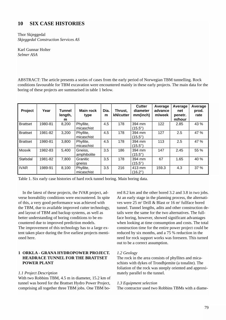
79
In the latest of these projects, the IVAR project, ad-verse boreability conditions were encountered. In spiteof this, a very good performance was achieved withthe TBM, due to available improved cutter technology,and layout of TBM and backup systems, as well asbetter understanding of boring conditions to be en-countered due to improved prediction models. The improvement of this technology has to a large ex-tent taken place during the five earliest projects menti-oned here.
1 ORKLA - GRANA HYDROPOWER PROJECT. HEADRACE TUNNEL FOR THE BRATTSETPOWER PLANT
1.1 Project DescriptionWith two Robbins TBM, 4.5 m in diameter, 15.2 km oftunnel was bored for the Brattset Hydro Power Project,comprising all together three TBM jobs. One TBM bo-
red 8.2 km and the other bored 3.2 and 3.8 in two jobs.At an early stage in the planning process, the alternati-ves were 25 m2 Drill & Blast or 16 m2 fullface boredtunnel. Tunnel lengths, adits and other construction de-tails were the same for the two alternatives. The full-face boring, however, showed significant advantageswhen looking at time consumption and costs. The totalconstruction time for the entire power project could bereduced by six months, and a 75 % reduction in theneed for rock support works was foreseen. This turnedout to be a correct assumption.
1.2 GeologyThe rock in the area consists of phyllites and mica-schists with dykes of Trondhjemite (a tonalite). The foliation of the rock was steeply oriented and approxi-mately parallel to the tunnel.
1.3 Equipment selectionThe contractor used two Robbins TBMs with a diame-
10 SIX CASE HISTORIES
Thor Skjeggedal Skjeggedal Construction Services AS
Karl Gunnar HolterSelmer ASA
ABSTRACT: The article presents a series of cases from the early period of Norwegian TBM tunnelling. Rockconditions favourable for TBM excavation were encountered mainly in these early projects. The main data for theboring of these projects are summarised in table 1 below.
Project Year Tunnellength,
m
Main rocktype
Dia.m
Thrust,kN/cutter
Cutterdiametermm(inch)
Averageadvancem/week
Averagenet
penetr.m/hour
Averageprod.rate
Brattset 1980-81 8,200 Phyllite,micaschist
4 5 178 394 mm(15 5'')
122 2 85 43 %
Brattset 1981-82 3,200 Phyllite,micaschist
4 5 178 394 mm(15 5'')
127 2 5 47 %
Brattset 1980-81 3,800 Phyllite,micaschist
4 5 178 394 mm(15 5'')
113 2 5 47 %
Mosvik 1982-83 5,400 Gneiss,amphibolite
3 5 186 394 mm(15 5'')
147 2 45 55 %
Stølsdal 1981-82 7,800 Graniticgneiss
3 5 178 394 mm(15 5'')
67 1 65 40 %
IVAR 1989-91 8,100 Phyllite,micaschist
3 5 216 413 mm(16 2'')
159 3 4 3 37 %
.
.
.
.
.
..
.
.
.
.
.
. .
.
.
.
.
.
Table 1. Six early case histories of hard rock tunnel boring. Main boring data.
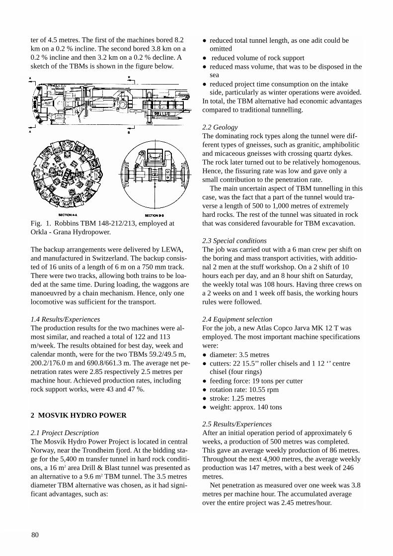
80
ter of 4.5 metres. The first of the machines bored 8.2km on a 0.2 % incline. The second bored 3.8 km on a0.2 % incline and then 3.2 km on a 0.2 % decline. Asketch of the TBMs is shown in the figure below.
Fig. 1. Robbins TBM 148-212/213, employed atOrkla - Grana Hydropower.
The backup arrangements were delivered by LEWA,and manufactured in Switzerland. The backup consis-ted of 16 units of a length of 6 m on a 750 mm track.There were two tracks, allowing both trains to be loa-ded at the same time. During loading, the waggons aremanoeuvred by a chain mechanism. Hence, only onelocomotive was sufficient for the transport.
1.4 Results/ExperiencesThe production results for the two machines were al-most similar, and reached a total of 122 and 113m/week. The results obtained for best day, week andcalendar month, were for the two TBMs 59.2/49.5 m,200.2/176.0 m and 690.8/661.3 m. The average net pe-netration rates were 2.85 respectively 2.5 metres permachine hour. Achieved production rates, includingrock support works, were 43 and 47 %.
2 MOSVIK HYDRO POWER
2.1 Project DescriptionThe Mosvik Hydro Power Project is located in centralNorway, near the Trondheim fjord. At the bidding sta-ge for the 5,400 m transfer tunnel in hard rock conditi-ons, a 16 m2 area Drill & Blast tunnel was presented asan alternative to a 9.6 m2 TBM tunnel. The 3.5 metresdiameter TBM alternative was chosen, as it had signi-ficant advantages, such as:
• reduced total tunnel length, as one adit could be omitted
• reduced volume of rock support• reduced mass volume, that was to be disposed in the
sea • reduced project time consumption on the intake
side, particularly as winter operations were avoided.In total, the TBM alternative had economic advantagescompared to traditional tunnelling.
2.2 GeologyThe dominating rock types along the tunnel were dif-ferent types of gneisses, such as granitic, amphiboliticand micaceous gneisses with crossing quartz dykes.The rock later turned out to be relatively homogenous.Hence, the fissuring rate was low and gave only asmall contribution to the penetration rate.
The main uncertain aspect of TBM tunnelling in thiscase, was the fact that a part of the tunnel would tra-verse a length of 500 to 1,000 metres of extremelyhard rocks. The rest of the tunnel was situated in rockthat was considered favourable for TBM excavation.
2.3 Special conditionsThe job was carried out with a 6 man crew per shift onthe boring and mass transport activities, with additio-nal 2 men at the stuff workshop. On a 2 shift of 10hours each per day, and an 8 hour shift on Saturday,the weekly total was 108 hours. Having three crews ona 2 weeks on and 1 week off basis, the working hoursrules were followed.
2.4 Equipment selectionFor the job, a new Atlas Copco Jarva MK 12 T wasemployed. The most important machine specificationswere:• diameter: 3.5 metres• cutters: 22 15.5’’ roller chisels and 1 12 ‘’ centre
chisel (four rings)• feeding force: 19 tons per cutter• rotation rate: 10.55 rpm• stroke: 1.25 metres• weight: approx. 140 tons
2.5 Results/ExperiencesAfter an initial operation period of approximately 6weeks, a production of 500 metres was completed.This gave an average weekly production of 86 metres.Throughout the next 4,900 metres, the average weeklyproduction was 147 metres, with a best week of 246metres.
Net penetration as measured over one week was 3.8metres per machine hour. The accumulated averageover the entire project was 2.45 metres/hour.
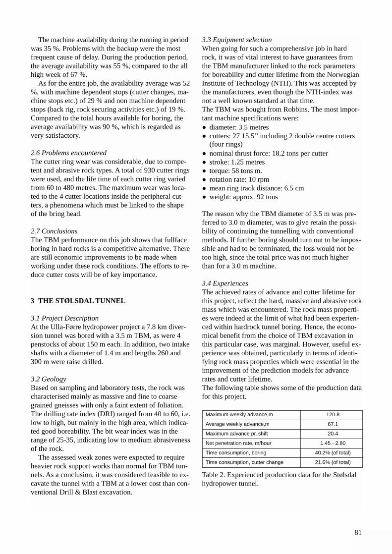
81
The machine availability during the running in periodwas 35 %. Problems with the backup were the mostfrequent cause of delay. During the production period,the average availability was 55 %, compared to the allhigh week of 67 %.
As for the entire job, the availability average was 52%, with machine dependent stops (cutter changes, ma-chine stops etc.) of 29 % and non machine dependentstops (back rig, rock securing activities etc.) of 19 %.Compared to the total hours available for boring, theaverage availability was 90 %, which is regarded asvery satisfactory.
2.6 Problems encountered The cutter ring wear was considerable, due to compe-tent and abrasive rock types. A total of 930 cutter ringswere used, and the life time of each cutter ring variedfrom 60 to 480 metres. The maximum wear was loca-ted to the 4 cutter locations inside the peripheral cut-ters, a phenomena which must be linked to the shapeof the bring head.
2.7 ConclusionsThe TBM performance on this job shows that fullfaceboring in hard rocks is a competitive alternative. Thereare still economic improvements to be made whenworking under these rock conditions. The efforts to re-duce cutter costs will be of key importance.
3 THE STØLSDAL TUNNEL
3.1 Project DescriptionAt the Ulla-Førre hydropower project a 7.8 km diver-sion tunnel was bored with a 3.5 m TBM, as were 4penstocks of about 150 m each. In addition, two intakeshafts with a diameter of 1.4 m and lengths 260 and300 m were raise drilled.
3.2 GeologyBased on sampling and laboratory tests, the rock wascharacterised mainly as massive and fine to coarsegrained gneisses with only a faint extent of foliation.The drilling rate index (DRI) ranged from 40 to 60, i.e.low to high, but mainly in the high area, which indica-ted good boreability. The bit wear index was in therange of 25-35, indicating low to medium abrasivenessof the rock.
The assessed weak zones were expected to requireheavier rock support works than normal for TBM tun-nels. As a conclusion, it was considered feasible to ex-cavate the tunnel with a TBM at a lower cost than con-ventional Drill & Blast excavation.
3.3 Equipment selectionWhen going for such a comprehensive job in hardrock, it was of vital interest to have guarantees fromthe TBM manufacturer linked to the rock parametersfor boreability and cutter lifetime from the NorwegianInstitute of Technology (NTH). This was accepted bythe manufacturers, even though the NTH-index wasnot a well known standard at that time. The TBM was bought from Robbins. The most impor-tant machine specifications were:• diameter: 3.5 metres• cutters: 27 15.5’’ including 2 double centre cutters
(four rings)• nominal thrust force: 18.2 tons per cutter• stroke: 1.25 metres• torque: 58 tons m.• rotation rate: 10 rpm• mean ring track distance: 6.5 cm• weight: approx. 92 tons
The reason why the TBM diameter of 3.5 m was pre-ferred to 3.0 m diameter, was to give retain the possi-bility of continuing the tunnelling with conventionalmethods. If further boring should turn out to be impos-sible and had to be terminated, the loss would not betoo high, since the total price was not much higherthan for a 3.0 m machine.
3.4 ExperiencesThe achieved rates of advance and cutter lifetime forthis project, reflect the hard, massive and abrasive rockmass which was encountered. The rock mass properti-es were indeed at the limit of what had been experien-ced within hardrock tunnel boring. Hence, the econo-mical benefit from the choice of TBM excavation inthis particular case, was marginal. However, useful ex-perience was obtained, particularly in terms of identi-fying rock mass properties which were essential in theimprovement of the prediction models for advance rates and cutter lifetime.The following table shows some of the production datafor this project.
Table 2. Experienced production data for the Stølsdalhydropower tunnel.
Maximum weekly advance,m 120.8
Average weekly advance,m 67.1
Maximum advance pr. shift 20.4
Net penetration rate, m/hour 1.45 - 2.80
Time consumption, boring 40.2% (of total)
Time consumption, cutter change 21.6% (of total)
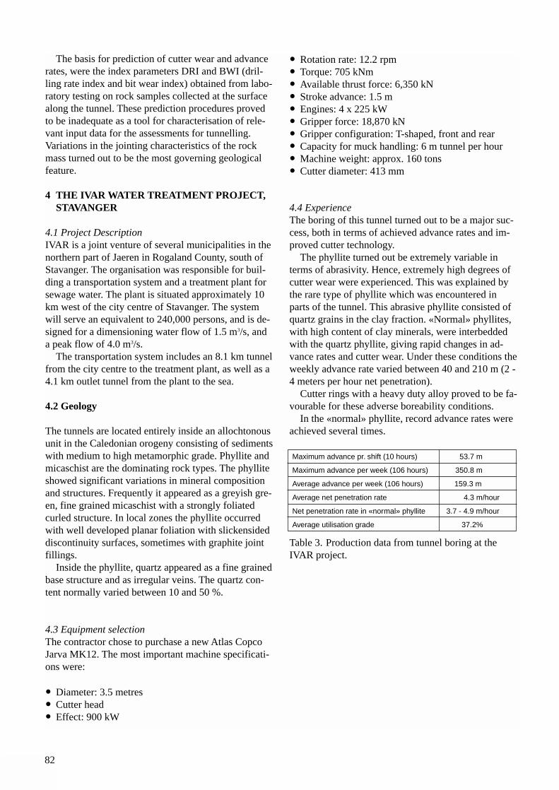
82
The basis for prediction of cutter wear and advancerates, were the index parameters DRI and BWI (dril-ling rate index and bit wear index) obtained from labo-ratory testing on rock samples collected at the surfacealong the tunnel. These prediction procedures provedto be inadequate as a tool for characterisation of rele-vant input data for the assessments for tunnelling.Variations in the jointing characteristics of the rockmass turned out to be the most governing geologicalfeature.
4 THE IVAR WATER TREATMENT PROJECT, STAVANGER
4.1 Project DescriptionIVAR is a joint venture of several municipalities in thenorthern part of Jaeren in Rogaland County, south ofStavanger. The organisation was responsible for buil-ding a transportation system and a treatment plant forsewage water. The plant is situated approximately 10km west of the city centre of Stavanger. The systemwill serve an equivalent to 240,000 persons, and is de-signed for a dimensioning water flow of 1.5 m3/s, anda peak flow of 4.0 m3/s.
The transportation system includes an 8.1 km tunnelfrom the city centre to the treatment plant, as well as a4.1 km outlet tunnel from the plant to the sea.
4.2 Geology
The tunnels are located entirely inside an allochtonousunit in the Caledonian orogeny consisting of sedimentswith medium to high metamorphic grade. Phyllite andmicaschist are the dominating rock types. The phylliteshowed significant variations in mineral compositionand structures. Frequently it appeared as a greyish gre-en, fine grained micaschist with a strongly foliatedcurled structure. In local zones the phyllite occurredwith well developed planar foliation with slickensideddiscontinuity surfaces, sometimes with graphite jointfillings.
Inside the phyllite, quartz appeared as a fine grainedbase structure and as irregular veins. The quartz con-tent normally varied between 10 and 50 %.
4.3 Equipment selectionThe contractor chose to purchase a new Atlas CopcoJarva MK12. The most important machine specificati-ons were:
• Diameter: 3.5 metres• Cutter head• Effect: 900 kW
• Rotation rate: 12.2 rpm• Torque: 705 kNm• Available thrust force: 6,350 kN• Stroke advance: 1.5 m• Engines: 4 x 225 kW• Gripper force: 18,870 kN• Gripper configuration: T-shaped, front and rear• Capacity for muck handling: 6 m tunnel per hour• Machine weight: approx. 160 tons• Cutter diameter: 413 mm
4.4 ExperienceThe boring of this tunnel turned out to be a major suc-cess, both in terms of achieved advance rates and im-proved cutter technology.
The phyllite turned out be extremely variable interms of abrasivity. Hence, extremely high degrees ofcutter wear were experienced. This was explained bythe rare type of phyllite which was encountered inparts of the tunnel. This abrasive phyllite consisted ofquartz grains in the clay fraction. «Normal» phyllites,with high content of clay minerals, were interbeddedwith the quartz phyllite, giving rapid changes in ad-vance rates and cutter wear. Under these conditions theweekly advance rate varied between 40 and 210 m (2 -4 meters per hour net penetration).
Cutter rings with a heavy duty alloy proved to be fa-vourable for these adverse boreability conditions.
In the «normal» phyllite, record advance rates wereachieved several times.
Table 3. Production data from tunnel boring at theIVAR project.
Maximum advance pr. shift (10 hours) 53.7 m
Maximum advance per week (106 hours) 350.8 m
Average advance per week (106 hours) 159.3 m
Average net penetration rate 4.3 m/hour
Net penetration rate in «normal» phyllite 3.7 - 4.9 m/hour
Average utilisation grade 37.2%
83
LITERATURE
Flønes, O. (1981): TBM-tunnelling at The Orkla-Grana Hydropower Project. Norwegian TunnellingConference, Oslo, 1981 (Norw.)
Holen, H. (1982): Fullface and raise drilling in hardrock at The Ulla-Førre Hydropower Project.Norwegian Tunnelling Conference, Oslo, 1982(Norw.)
Larsen, S. I. (1983): TBM-tunnelling at MosvikHydropower. Norwegian Tunnelling Conference, Oslo,1983 (Norw.)
Asting, G. (1990): North Jaeren central sewage treat-ment plant in rock. Norwegian Tunnelling Conference,Oslo, 1990 (Norw.)

84
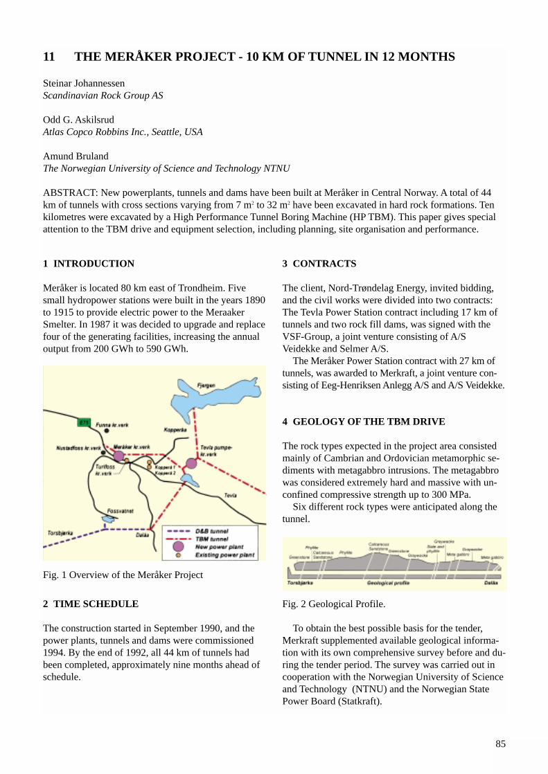
85
1 INTRODUCTION
Meråker is located 80 km east of Trondheim. Fivesmall hydropower stations were built in the years 1890to 1915 to provide electric power to the MeraakerSmelter. In 1987 it was decided to upgrade and replacefour of the generating facilities, increasing the annualoutput from 200 GWh to 590 GWh.
Fig. 1 Overview of the Meråker Project
2 TIME SCHEDULE
The construction started in September 1990, and thepower plants, tunnels and dams were commissioned1994. By the end of 1992, all 44 km of tunnels hadbeen completed, approximately nine months ahead ofschedule.
3 CONTRACTS
The client, Nord-Trøndelag Energy, invited bidding,and the civil works were divided into two contracts:The Tevla Power Station contract including 17 km oftunnels and two rock fill dams, was signed with theVSF-Group, a joint venture consisting of A/SVeidekke and Selmer A/S.
The Meråker Power Station contract with 27 km oftunnels, was awarded to Merkraft, a joint venture con-sisting of Eeg-Henriksen Anlegg A/S and A/S Veidekke.
4 GEOLOGY OF THE TBM DRIVE
The rock types expected in the project area consistedmainly of Cambrian and Ordovician metamorphic se-diments with metagabbro intrusions. The metagabbrowas considered extremely hard and massive with un-confined compressive strength up to 300 MPa.
Six different rock types were anticipated along the tunnel.
Fig. 2 Geological Profile.
To obtain the best possible basis for the tender,Merkraft supplemented available geological informa-tion with its own comprehensive survey before and du-ring the tender period. The survey was carried out incooperation with the Norwegian University of Scienceand Technology (NTNU) and the Norwegian StatePower Board (Statkraft).
11 THE MERÅKER PROJECT - 10 KM OF TUNNEL IN 12 MONTHS
Steinar JohannessenScandinavian Rock Group AS
Odd G. AskilsrudAtlas Copco Robbins Inc., Seattle, USA
Amund BrulandThe Norwegian University of Science and Technology NTNU
ABSTRACT: New powerplants, tunnels and dams have been built at Meråker in Central Norway. A total of 44km of tunnels with cross sections varying from 7 m2 to 32 m2 have been excavated in hard rock formations. Tenkilometres were excavated by a High Performance Tunnel Boring Machine (HP TBM). This paper gives specialattention to the TBM drive and equipment selection, including planning, site organisation and performance.
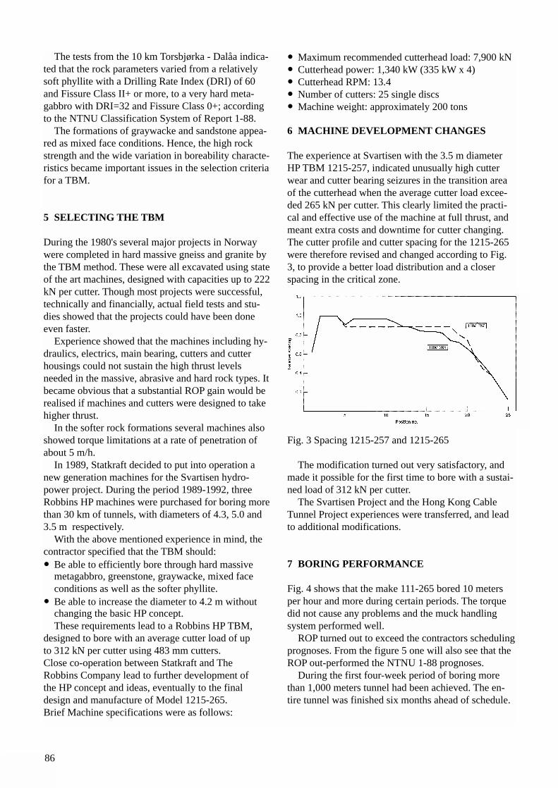
86
The tests from the 10 km Torsbjørka - Dalåa indica-ted that the rock parameters varied from a relativelysoft phyllite with a Drilling Rate Index (DRI) of 60and Fissure Class II+ or more, to a very hard meta-gabbro with DRI=32 and Fissure Class 0+; accordingto the NTNU Classification System of Report 1-88.
The formations of graywacke and sandstone appea-red as mixed face conditions. Hence, the high rockstrength and the wide variation in boreability characte-ristics became important issues in the selection criteriafor a TBM.
5 SELECTING THE TBM
During the 1980's several major projects in Norwaywere completed in hard massive gneiss and granite bythe TBM method. These were all excavated using stateof the art machines, designed with capacities up to 222kN per cutter. Though most projects were successful,technically and financially, actual field tests and stu-dies showed that the projects could have been doneeven faster.
Experience showed that the machines including hy-draulics, electrics, main bearing, cutters and cutterhousings could not sustain the high thrust levels needed in the massive, abrasive and hard rock types. It became obvious that a substantial ROP gain would berealised if machines and cutters were designed to takehigher thrust.
In the softer rock formations several machines alsoshowed torque limitations at a rate of penetration ofabout 5 m/h.
In 1989, Statkraft decided to put into operation anew generation machines for the Svartisen hydro-power project. During the period 1989-1992, threeRobbins HP machines were purchased for boring morethan 30 km of tunnels, with diameters of 4.3, 5.0 and3.5 m respectively.
With the above mentioned experience in mind, thecontractor specified that the TBM should:• Be able to efficiently bore through hard massive
metagabbro, greenstone, graywacke, mixed face conditions as well as the softer phyllite.
• Be able to increase the diameter to 4.2 m without changing the basic HP concept.These requirements lead to a Robbins HP TBM,
designed to bore with an average cutter load of up to 312 kN per cutter using 483 mm cutters.Close co-operation between Statkraft and The Robbins Company lead to further development of the HP concept and ideas, eventually to the final design and manufacture of Model 1215-265.Brief Machine specifications were as follows:
• Maximum recommended cutterhead load: 7,900 kN• Cutterhead power: 1,340 kW (335 kW x 4)• Cutterhead RPM: 13.4• Number of cutters: 25 single discs• Machine weight: approximately 200 tons
6 MACHINE DEVELOPMENT CHANGES
The experience at Svartisen with the 3.5 m diameterHP TBM 1215-257, indicated unusually high cutterwear and cutter bearing seizures in the transition areaof the cutterhead when the average cutter load excee-ded 265 kN per cutter. This clearly limited the practi-cal and effective use of the machine at full thrust, andmeant extra costs and downtime for cutter changing.The cutter profile and cutter spacing for the 1215-265were therefore revised and changed according to Fig.3, to provide a better load distribution and a closerspacing in the critical zone.
Fig. 3 Spacing 1215-257 and 1215-265
The modification turned out very satisfactory, andmade it possible for the first time to bore with a sustai-ned load of 312 kN per cutter.
The Svartisen Project and the Hong Kong CableTunnel Project experiences were transferred, and leadto additional modifications.
7 BORING PERFORMANCE
Fig. 4 shows that the make 111-265 bored 10 metersper hour and more during certain periods. The torquedid not cause any problems and the muck handlingsystem performed well.
ROP turned out to exceed the contractors schedulingprognoses. From the figure 5 one will also see that theROP out-performed the NTNU 1-88 prognoses.
During the first four-week period of boring morethan 1,000 meters tunnel had been achieved. The en-tire tunnel was finished six months ahead of schedule.
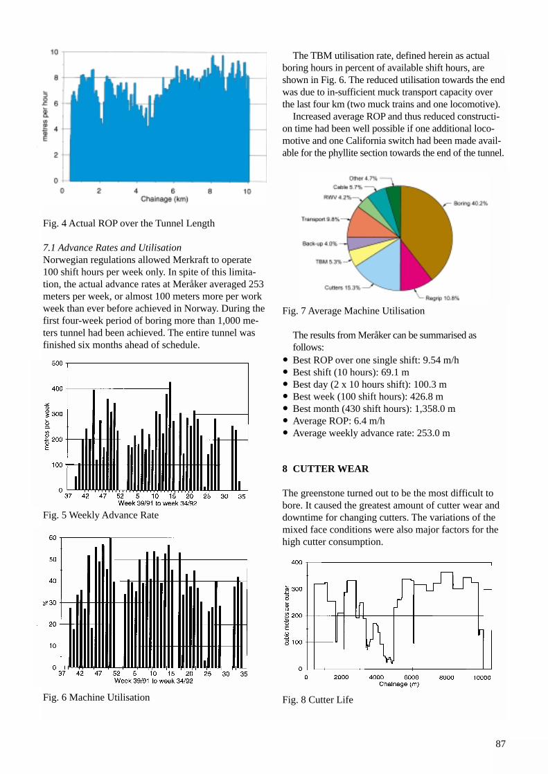
87
Fig. 4 Actual ROP over the Tunnel Length
7.1 Advance Rates and UtilisationNorwegian regulations allowed Merkraft to operate100 shift hours per week only. In spite of this limita-tion, the actual advance rates at Meråker averaged 253meters per week, or almost 100 meters more per workweek than ever before achieved in Norway. During thefirst four-week period of boring more than 1,000 me-ters tunnel had been achieved. The entire tunnel wasfinished six months ahead of schedule.
Fig. 5 Weekly Advance Rate
Fig. 6 Machine Utilisation
The TBM utilisation rate, defined herein as actual boring hours in percent of available shift hours, areshown in Fig. 6. The reduced utilisation towards the endwas due to in-sufficient muck transport capacity overthe last four km (two muck trains and one locomotive).
Increased average ROP and thus reduced constructi-on time had been well possible if one additional loco-motive and one California switch had been made avail-able for the phyllite section towards the end of the tunnel.
Fig. 7 Average Machine Utilisation
The results from Meråker can be summarised as follows:
• Best ROP over one single shift: 9.54 m/h• Best shift (10 hours): 69.1 m• Best day (2 x 10 hours shift): 100.3 m• Best week (100 shift hours): 426.8 m• Best month (430 shift hours): 1,358.0 m• Average ROP: 6.4 m/h• Average weekly advance rate: 253.0 m
8 CUTTER WEAR
The greenstone turned out to be the most difficult tobore. It caused the greatest amount of cutter wear anddowntime for changing cutters. The variations of themixed face conditions were also major factors for thehigh cutter consumption.
Fig. 8 Cutter Life
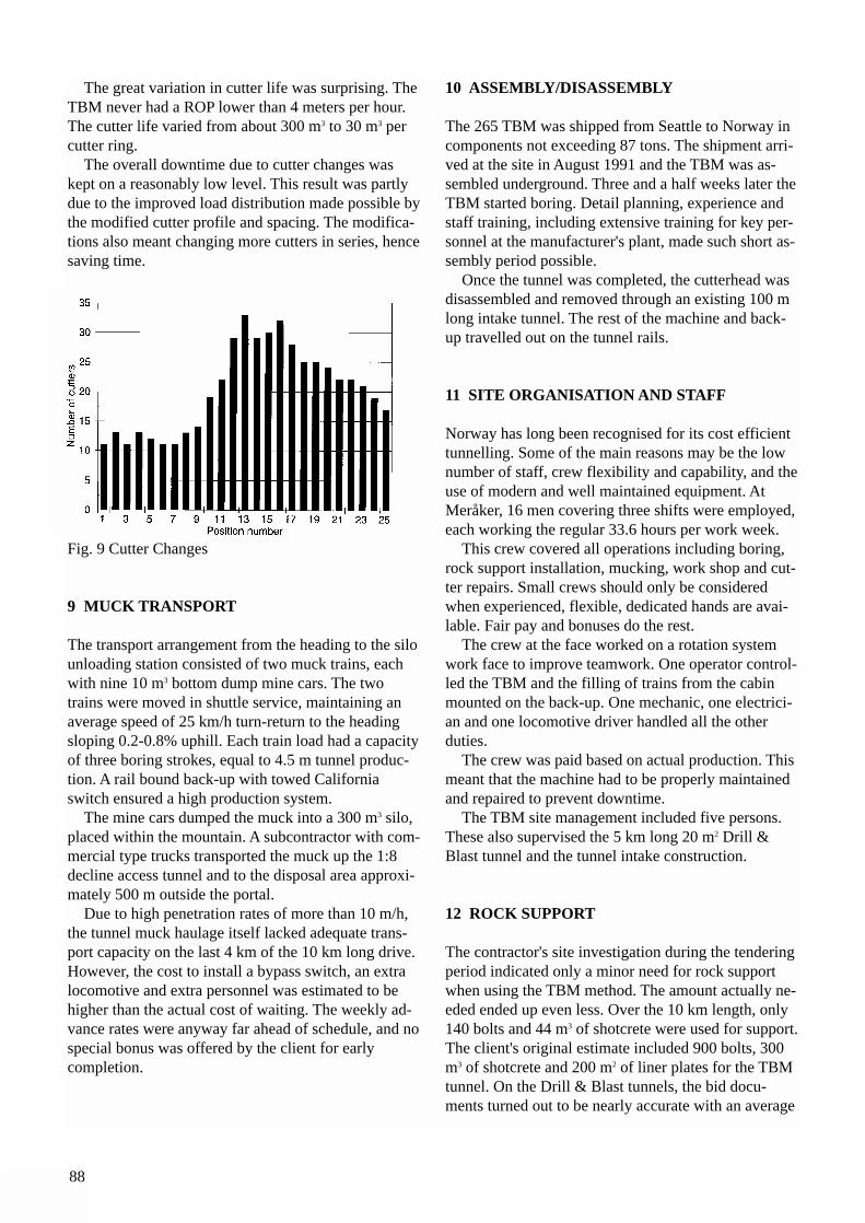
88
The great variation in cutter life was surprising. TheTBM never had a ROP lower than 4 meters per hour.The cutter life varied from about 300 m3 to 30 m3 percutter ring.
The overall downtime due to cutter changes waskept on a reasonably low level. This result was partlydue to the improved load distribution made possible bythe modified cutter profile and spacing. The modifica-tions also meant changing more cutters in series, hencesaving time.
Fig. 9 Cutter Changes
9 MUCK TRANSPORT
The transport arrangement from the heading to the silounloading station consisted of two muck trains, eachwith nine 10 m3 bottom dump mine cars. The twotrains were moved in shuttle service, maintaining anaverage speed of 25 km/h turn-return to the headingsloping 0.2-0.8% uphill. Each train load had a capacityof three boring strokes, equal to 4.5 m tunnel produc-tion. A rail bound back-up with towed Californiaswitch ensured a high production system.
The mine cars dumped the muck into a 300 m3 silo,placed within the mountain. A subcontractor with com-mercial type trucks transported the muck up the 1:8decline access tunnel and to the disposal area approxi-mately 500 m outside the portal.
Due to high penetration rates of more than 10 m/h,the tunnel muck haulage itself lacked adequate trans-port capacity on the last 4 km of the 10 km long drive.However, the cost to install a bypass switch, an extralocomotive and extra personnel was estimated to behigher than the actual cost of waiting. The weekly ad-vance rates were anyway far ahead of schedule, and nospecial bonus was offered by the client for early completion.
10 ASSEMBLY/DISASSEMBLY
The 265 TBM was shipped from Seattle to Norway incomponents not exceeding 87 tons. The shipment arri-ved at the site in August 1991 and the TBM was as-sembled underground. Three and a half weeks later theTBM started boring. Detail planning, experience andstaff training, including extensive training for key per-sonnel at the manufacturer's plant, made such short as-sembly period possible.
Once the tunnel was completed, the cutterhead wasdisassembled and removed through an existing 100 mlong intake tunnel. The rest of the machine and back-up travelled out on the tunnel rails.
11 SITE ORGANISATION AND STAFF
Norway has long been recognised for its cost efficienttunnelling. Some of the main reasons may be the lownumber of staff, crew flexibility and capability, and theuse of modern and well maintained equipment. AtMeråker, 16 men covering three shifts were employed,each working the regular 33.6 hours per work week.
This crew covered all operations including boring,rock support installation, mucking, work shop and cut-ter repairs. Small crews should only be consideredwhen experienced, flexible, dedicated hands are avai-lable. Fair pay and bonuses do the rest.
The crew at the face worked on a rotation systemwork face to improve teamwork. One operator control-led the TBM and the filling of trains from the cabinmounted on the back-up. One mechanic, one electrici-an and one locomotive driver handled all the other duties.
The crew was paid based on actual production. Thismeant that the machine had to be properly maintainedand repaired to prevent downtime.
The TBM site management included five persons.These also supervised the 5 km long 20 m2 Drill &Blast tunnel and the tunnel intake construction.
12 ROCK SUPPORT
The contractor's site investigation during the tenderingperiod indicated only a minor need for rock supportwhen using the TBM method. The amount actually ne-eded ended up even less. Over the 10 km length, only140 bolts and 44 m3 of shotcrete were used for support.The client's original estimate included 900 bolts, 300m3 of shotcrete and 200 m2 of liner plates for the TBMtunnel. On the Drill & Blast tunnels, the bid docu-ments turned out to be nearly accurate with an average
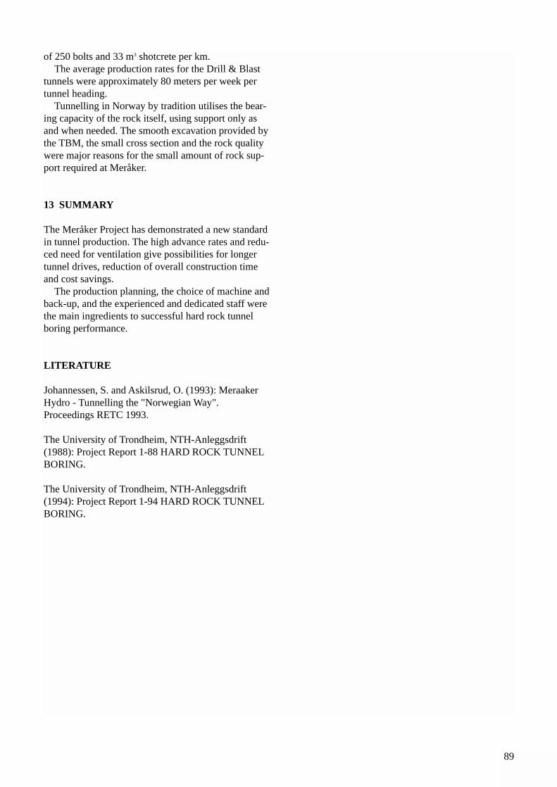
89
of 250 bolts and 33 m3 shotcrete per km. The average production rates for the Drill & Blast
tunnels were approximately 80 meters per week pertunnel heading.
Tunnelling in Norway by tradition utilises the bear-ing capacity of the rock itself, using support only asand when needed. The smooth excavation provided bythe TBM, the small cross section and the rock qualitywere major reasons for the small amount of rock sup-port required at Meråker.
13 SUMMARY
The Meråker Project has demonstrated a new standardin tunnel production. The high advance rates and redu-ced need for ventilation give possibilities for longertunnel drives, reduction of overall construction timeand cost savings.
The production planning, the choice of machine andback-up, and the experienced and dedicated staff werethe main ingredients to successful hard rock tunnel boring performance.
LITERATURE
Johannessen, S. and Askilsrud, O. (1993): MeraakerHydro - Tunnelling the "Norwegian Way".Proceedings RETC 1993.
The University of Trondheim, NTH-Anleggsdrift(1988): Project Report 1-88 HARD ROCK TUNNELBORING.
The University of Trondheim, NTH-Anleggsdrift(1994): Project Report 1-94 HARD ROCK TUNNELBORING.

90
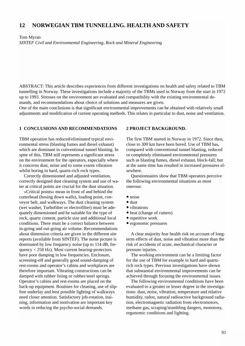
91
1 CONCLUSIONS AND RECOMMENDATIONS
TBM operation has reduced/eliminated typical envi-ronmental stress (blasting fumes and diesel exhaust)which are dominant in conventional tunnel blasting. Inspite of this, TBM still represents a significant stresson the environment for the operators, especially whereit concerns dust, noise and to some extent vibrationwhilst boring in hard, quartz-rich rock types.
Correctly dimensioned and adjusted ventilation,correctly designed dust cleaning system and use of wa-ter at critical points are crucial for the dust situation.
«Critical points» mean in front of and behind thecutterhead (hosing down walls), loading point, con-veyor belt, and walkways. The dust cleaning system(wet washer, Turbofilter or electrofilter) must be ade-quately dimensioned and be suitable for the type ofrock, quartz content, particle size and additional localconditions. There must be a correct balance betweenin-going and out-going air volume. Recommendationsabout dimension criteria are given in the different sitereports (available from SINTEF). The noise picture isdominated by low frequency noise (up to 114 dB, fre-quency < 250 Hz). Most current hearing-protectorshave poor damping in low frequencies. Enclosure,screening-off and generally good sound-damping ofrest-rooms and operator’s cabins and workplaces aretherefore important. Vibrating constructions can bedamped with rubber lining or rubber/steel springs.Operator’s cabins and rest-rooms are placed on theback-up equipment. Routines for cleaning, use of slip-free underlay and best possible lighting of walkwaysneed closer attention. Satisfactory job-rotation, trai-ning, information and motivation are important keywords in reducing the psycho-social demands.
2 PROJECT BACKGROUND.
The first TBM started in Norway in 1972. Since then,close to 300 km have been bored. Use of TBM has,compared with conventional tunnel blasting, reducedor completely eliminated environmental pressuressuch as blasting fumes, diesel exhaust, block-fall; butat the same time has resulted in increased pressures el-sewhere.
Questionnaires show that TBM operators perceivethe following environmental situations as most onerous:
• noise• dust• vibrations• heat (change of cutters)• repetitive work• ergonomic pressures
A clear majority fear health risk on account of long-term effects of dust, noise and vibration more than therisk of accidents of acute, mechanical character orpressure injuries.
The working environment can be a limiting factorfor the use of TBM for example in hard and quartz-rich rock types. Previous investigations have shownthat substantial environmental improvements can beachieved through focusing the environmental issues.
The following environmental conditions have beenevaluated to a greater or lesser degree in the investiga-tions: dust, noise, vibration, temperature and relativehumidity, radon, natural radioactive background radia-tion, electromagnetic radiation from electromotors,methane gas, scraping/stumbling dangers, monotony,ergonomic conditions and lighting.
12 NORWEGIAN TBM TUNNELLING. HEALTH AND SAFETY
Tom MyranSINTEF Civil and Environmental Engineering, Rock and Mineral Engineering
ABSTRACT: This article describes experiences from different investigations on health and safety related to TBMtunnelling in Norway. These investigations include a majority of the TBMs used in Norway from the start in 1972up to 1993. Stresses on the environment are evaluated and compatibility with the existing environmental de-mands, and recommendations about choice of solutions and measures are given.One of the main conclusions is that significant environmental improvements can be obtained with relatively smalladjustments and modification of current operating methods. This relates in particular to dust, noise and ventilation.
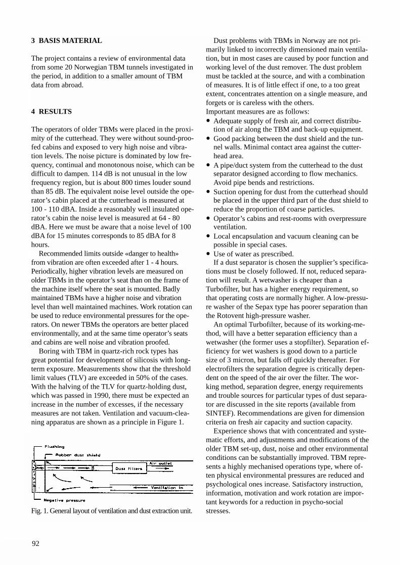
92
3 BASIS MATERIAL
The project contains a review of environmental datafrom some 20 Norwegian TBM tunnels investigated inthe period, in addition to a smaller amount of TBMdata from abroad.
4 RESULTS
The operators of older TBMs were placed in the proxi-mity of the cutterhead. They were without sound-proo-fed cabins and exposed to very high noise and vibra-tion levels. The noise picture is dominated by low fre-quency, continual and monotonous noise, which can bedifficult to dampen. 114 dB is not unusual in the lowfrequency region, but is about 800 times louder soundthan 85 dB. The equivalent noise level outside the ope-rator’s cabin placed at the cutterhead is measured at100 - 110 dBA. Inside a reasonably well insulated ope-rator’s cabin the noise level is measured at 64 - 80dBA. Here we must be aware that a noise level of 100dBA for 15 minutes corresponds to 85 dBA for 8hours.
Recommended limits outside «danger to health»from vibration are often exceeded after 1 - 4 hours.Periodically, higher vibration levels are measured on older TBMs in the operator’s seat than on the frame ofthe machine itself where the seat is mounted. Badlymaintained TBMs have a higher noise and vibration level than well maintained machines. Work rotation canbe used to reduce environmental pressures for the ope-rators. On newer TBMs the operators are better placed environmentally, and at the same time operator’s seatsand cabins are well noise and vibration proofed.
Boring with TBM in quartz-rich rock types has great potential for development of silicosis with long-term exposure. Measurements show that the thresholdlimit values (TLV) are exceeded in 50% of the cases.With the halving of the TLV for quartz-holding dust,which was passed in 1990, there must be expected anincrease in the number of excesses, if the necessarymeasures are not taken. Ventilation and vacuum-clea-ning apparatus are shown as a principle in Figure 1.
Fig. 1. General layout of ventilation and dust extraction unit.
Dust problems with TBMs in Norway are not pri-marily linked to incorrectly dimensioned main ventila-tion, but in most cases are caused by poor function andworking level of the dust remover. The dust problemmust be tackled at the source, and with a combinationof measures. It is of little effect if one, to a too greatextent, concentrates attention on a single measure, andforgets or is careless with the others.Important measures are as follows: • Adequate supply of fresh air, and correct distribu-
tion of air along the TBM and back-up equipment.• Good packing between the dust shield and the tun-
nel walls. Minimal contact area against the cutter-head area.
• A pipe/duct system from the cutterhead to the dust separator designed according to flow mechanics. Avoid pipe bends and restrictions.
• Suction opening for dust from the cutterhead shouldbe placed in the upper third part of the dust shield toreduce the proportion of coarse particles.
• Operator’s cabins and rest-rooms with overpressure ventilation.
• Local encapsulation and vacuum cleaning can be possible in special cases.
• Use of water as prescribed.If a dust separator is chosen the supplier’s specifica-
tions must be closely followed. If not, reduced separa-tion will result. A wetwasher is cheaper than aTurbofilter, but has a higher energy requirement, sothat operating costs are normally higher. A low-pressu-re washer of the Sepax type has poorer separation thanthe Rotovent high-pressure washer.
An optimal Turbofilter, because of its working-me-thod, will have a better separation efficiency than awetwasher (the former uses a stopfilter). Separation ef-ficiency for wet washers is good down to a particlesize of 3 micron, but falls off quickly thereafter. Forelectrofilters the separation degree is critically depen-dent on the speed of the air over the filter. The wor-king method, separation degree, energy requirementsand trouble sources for particular types of dust separa-tor are discussed in the site reports (available fromSINTEF). Recommendations are given for dimensioncriteria on fresh air capacity and suction capacity.
Experience shows that with concentrated and syste-matic efforts, and adjustments and modifications of theolder TBM set-up, dust, noise and other environmentalconditions can be substantially improved. TBM repre-sents a highly mechanised operations type, where of-ten physical environmental pressures are reduced andpsychological ones increase. Satisfactory instruction,information, motivation and work rotation are impor-tant keywords for a reduction in psycho-social stresses.

93
Emission of radioactive radon gas, or methane gaswhich can ignite and explode, are often local in effectand difficult to predict in advance. Both radon andmethane are of secondary interest in Norway.
Electrical installations and motors can cause highelectromagnetic fields with risk for health injury.Investigations show that exposure is low, but a littlehigher than one is exposed to in a normal living situation.
The project on TBM Health and Safety has givenuseful information and knowledge about a series ofwork environment conditions involving TBM opera-tions, of which only a few dominate, i.e. dust, noise,vibration.

94
95
1 CONSTRUCTION TIME
1.1 Excavation time for different types of rock andcross sectionA general statement is that the progress of TBM boringis much higher than with Drill & Blast (D&B).However, the progress in TBM boring is much moredependent on the rock conditions than D&B. The pro-gress of D&B may vary some 20% due to drillabilityand necessary number of holes, while the progress ofTBM boring may vary more than 500%. In some veryspecial cases the progress with D&B may even be higher than with TBM.
Internationally, the compressive strength is the mostcommonly used rock parameter when assessing aTBM-project.
In this country however, a set of parameters as de-veloped by the Norwegian University of Science andTechnology, NTNU, are commonly taken into conside-rations.
These are:• Drilling Rate Index• Fracturing. Type, orientation and spacing of fissures• Abrasiveness and porosity
The main machine parameters for TBM are:• Cutter thrust• RPM• Cutter size and spacing
For very hard rock the penetration when boring maybe drastically reduced if the machine parameters donot meet the actual rock parameters.
For D&B the modern Jumbos with hydraulic ham-mers will be of sufficient strength, and the boring timefor one round does not differ very much.
A good weekly production for D&B is 80 m forcross sections of 50 m2; and more than 100 meters for
smaller cross sections. For TBM a good productionmay be in the range between 150 and 400 meters dependent on rock conditions, machine parameters anddiameter.
1.2. Time for erection and dismantlingA new drilling jumbo has a short delivery time and isoperational when it arrives on site.
For TBMs, it takes more time. If a new TBM has tobe purchased, the delivery time is 6-12 months. If a se-cond-hand TBM is to be used, it has to be modified tofit to the actual job, and a general overhaul may be re-quired.
While a boomer can easily be brought to a work-shop and repaired, repairs of TBMs, after boring hasstarted, have to be done in the tunnel. To bring in aspare boomer is normally possible, while bringing in aspare TBM may take a year or more. Therefore a tho-rough pre-operation overhaul of TBMs is more vitalthan of a boomer.
A boomer is flexible regarding cross sections. Thediameter of a TBM can be changed to some extent, butonce it’s in the tunnel it is a very time-consuming ope-ration to do diameter modifications. It is, however,possible.
A TBM and backup have to be transported in pieces.Erection time varies dependent on local conditions,crane support etc. and takes normally 3-6 weeks (small& medium sized hard rock TBMs).
1.3. Time for rock supportRock support is normally reduced by TBM boringcompared with D&B. Time for rock support dependsvery much on how the TBM is equipped with rocksupport equipment, like drilling equipment for boltingand grouting, shotcrete equipment, liner plate erector
13 TBM VS DRILL & BLAST TUNNELLING
Hallvard HolenStatkraft Anlegg AS
ABSTRACT: In Norway around 5,000 km of tunnels have been excavated. Out of this, 29 tunnels with a totallength of 173 km have been bored with TBMs. Most of the bored tunnels are in hydro power construction. Based on this experience, pros & contras for choosing TBMs or not is discussed in this article. Today TBM tunnelling is a very competitive alternative for long tunnels also in hard rock, and first of all for wa-ter tunnels. TBM is, however, also a realistic alternative for other tunnels, like road and railway tunnels.
96
etc. If well equipped, bolting and shotcreting may becarried out during boring. For D&B, rock support atfront can not be done during excavation.
Rock support is adapted to the actual needs. Syste-matic rock support is never specified. TBMs are henceequipped for bolting “as decided” only, sometimeswith grouting equipment. Additional equipment, e.g.shotcreting equipment, has to be brought in when needed.
2 COSTS
2.1 Transport, Rigging and ErectionEquipment for D&B can normally be transported as itis, and costs for transport and erection are a very smallpart of the total cost.
For TBM it is different. The weight of the TBM ismuch higher than of a boomer and is in the range of200-1,000 tons plus the weight of the back-up equip-ment. The TBM and backup have to be dismantled,and the heaviest piece will be 50-100 tons.Strengthening of roads and bridges may be necessary,and big cranes are required for erection.
Rigging is also different. Rigging for TBM is de-pendent on the muck handling system and if the TBMrigging is done in a cavern or outside the tunnel. Total costs for transport, specific TBM rigging anderection are often in the range of 5-10% of the excava-tion costs, but will of course vary a lot.
2.2 ExcavationThe excavation costs for D&B are to some extent de-pendent on the number of holes required, consumptionof explosives and wear of drilling steel, but do notvary very much.For TBMs the excavation costs vary a lot and aremainly influenced by the following factors:• Capital costs which are much higher than for D&B.• Net penetration that can vary from less than 1
m/hour to more than 6 m/hour depending on rock conditions and TBM specifications.
• Cutter wear that can vary from next to nothing to 50USD/m3 or even more.
2.3. Rock supportNeed for rock support is drastically reduced with TBM,under normal conditions to 30-50%. The reason is obvi-ous; rock stresses from the detonations are eliminated.
If very serious rock problems like rock slides oc-curs, it may be more time consuming and costly to car-ry out the rock support, especially if the TBM is notequipped with the necessary devices. The reason isthat there is limited space for carrying out the work
and that it is difficult to bring in the necessary equip-ment and material through the back-up.2.4. Comparison of costsErection and capital costs are higher for TBM, whilemarginal costs for the excavation phase are less.Therefore, the tunnel has to exceed a certain length tobe economical with TBM; minimum length for choo-sing TBM for economical reasons is 5-6 km. If thereare restrictions regarding D&B like vibrations fromthe blastings, TBM may be the right alternative alsofor shorter tunnels.
The optimal length for a D&B tunnel is normallyapproximately 3 km and for a TBM tunnel 8 km. Themarginal unit rate per meter increases more for a D&Btunnel than for a TBM tunnel. The high TBM capitaland installation costs can be distributed on more tunnelmeters. For D&B tunnels additional length may causeadditional ventilation at prohibitive expenses.
3 GENERAL LAYOUT
3.1 Curve radiusFor D&B there are normally no practical limitationsregarding curves. For TBMs, narrow curves may causeproblems.
The TBM itself can pass a minimum radius of 40-80m, but the backup equipment determines the minimumradius. That can be from 150 to 450 m when boring. Itis, on the other side, possible to transport a TBMthrough an already excavated tunnel with reduced ra-dius. The Project layout therefore has to take this mat-ter into account.
3.2 Tunnel slopeThe TBM itself can bore any slope, for steep slopesextra grippers have to be installed. The limitation isagain the backup and transportation systems. In prin-ciple the options regarding transportation are the samefor TBM and D&B. That is; normal railbound trans-port is limited to 2% and preferably to 0.7%. For TBMdiameters of 7 meters or more trackless transport is feasible, while the diameter for D&B may be smallerbecause meeting niches are much cheaper, and thecross section is more flexible.
Conveyor transport of spoil is a good alternativeand the slope may be up to approximately 30 degrees.It is required to have vehicles to bring in operators,cutters, spare parts, rock support equipment and mate-rials etc., and that limits the slope to 1:5. For steeperslopes a winch operated waggon may be utilised.
For shafts the slope is normally 45-60 degrees. Therock debris has to be taken care of in a tube or channel.
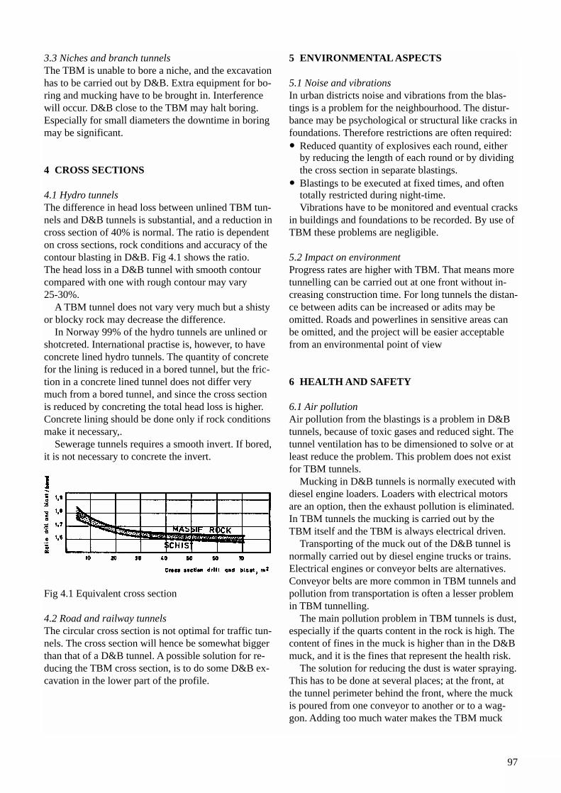
97
3.3 Niches and branch tunnelsThe TBM is unable to bore a niche, and the excavationhas to be carried out by D&B. Extra equipment for bo-ring and mucking have to be brought in. Interferencewill occur. D&B close to the TBM may halt boring.Especially for small diameters the downtime in boringmay be significant.
4 CROSS SECTIONS
4.1 Hydro tunnelsThe difference in head loss between unlined TBM tun-nels and D&B tunnels is substantial, and a reduction incross section of 40% is normal. The ratio is dependenton cross sections, rock conditions and accuracy of thecontour blasting in D&B. Fig 4.1 shows the ratio.The head loss in a D&B tunnel with smooth contourcompared with one with rough contour may vary 25-30%.
A TBM tunnel does not vary very much but a shistyor blocky rock may decrease the difference.
In Norway 99% of the hydro tunnels are unlined orshotcreted. International practise is, however, to haveconcrete lined hydro tunnels. The quantity of concretefor the lining is reduced in a bored tunnel, but the fric-tion in a concrete lined tunnel does not differ verymuch from a bored tunnel, and since the cross sectionis reduced by concreting the total head loss is higher.Concrete lining should be done only if rock conditionsmake it necessary,.
Sewerage tunnels requires a smooth invert. If bored,it is not necessary to concrete the invert.
Fig 4.1 Equivalent cross section
4.2 Road and railway tunnelsThe circular cross section is not optimal for traffic tun-nels. The cross section will hence be somewhat biggerthan that of a D&B tunnel. A possible solution for re-ducing the TBM cross section, is to do some D&B ex-cavation in the lower part of the profile.
5 ENVIRONMENTAL ASPECTS
5.1 Noise and vibrationsIn urban districts noise and vibrations from the blas-tings is a problem for the neighbourhood. The distur-bance may be psychological or structural like cracks infoundations. Therefore restrictions are often required: • Reduced quantity of explosives each round, either
by reducing the length of each round or by dividing the cross section in separate blastings.
• Blastings to be executed at fixed times, and often totally restricted during night-time.Vibrations have to be monitored and eventual cracks
in buildings and foundations to be recorded. By use ofTBM these problems are negligible.
5.2 Impact on environmentProgress rates are higher with TBM. That means moretunnelling can be carried out at one front without in-creasing construction time. For long tunnels the distan-ce between adits can be increased or adits may be omitted. Roads and powerlines in sensitive areas canbe omitted, and the project will be easier acceptablefrom an environmental point of view
6 HEALTH AND SAFETY
6.1 Air pollutionAir pollution from the blastings is a problem in D&Btunnels, because of toxic gases and reduced sight. Thetunnel ventilation has to be dimensioned to solve or atleast reduce the problem. This problem does not existfor TBM tunnels.
Mucking in D&B tunnels is normally executed withdiesel engine loaders. Loaders with electrical motorsare an option, then the exhaust pollution is eliminated.In TBM tunnels the mucking is carried out by theTBM itself and the TBM is always electrical driven.
Transporting of the muck out of the D&B tunnel isnormally carried out by diesel engine trucks or trains.Electrical engines or conveyor belts are alternatives.Conveyor belts are more common in TBM tunnels andpollution from transportation is often a lesser problemin TBM tunnelling.
The main pollution problem in TBM tunnels is dust,especially if the quarts content in the rock is high. Thecontent of fines in the muck is higher than in the D&Bmuck, and it is the fines that represent the health risk.
The solution for reducing the dust is water spraying.This has to be done at several places; at the front, atthe tunnel perimeter behind the front, where the muckis poured from one conveyor to another or to a wag-gon. Adding too much water makes the TBM muck
98
adhesive which may create problems in emptyingtransport units.
6.2 Physical stresses The operators of a TBM or drilling rig are exposed tonoise and vibrations. This can be reduced to an accep-table level by installing an insulated and vibrationdampened operator’s cabin. The problem for the crewoccurs when additional tasks have to be done outsidethe operator’s cabin, like rock support, rail erections,charging during boring etc. The noise from a jumbo isstill higher than from a TBM, but on the whole there isno significant difference between the methods regar-ding noise.
A special problem in TBM boring is cutter change, due to high temperature and disagreeable working conditions.
6.3 Risk for accidentsThe risk for serious accidents from handling explo-sives is eliminated by TBM tunnelling. There are nostatistical support or evidence for one method beingsafer than the other.
99
1 INTRODUCTION
The TBM technology has existed for approximately 50years. Over the years, the tunnel boring technology hasresponded to a wide variety of demands from contrac-tors and developers or clients. The technology is cur-rently able to cope with ground conditions from verysoft clay, sand, etc. to hard rock. At the hard rock end,the limits of economic boreable rock conditions havebeen moved considerably over the last 10 years or so.This paper will concentrate on demands and develop-ment of hard rock related tunnel boring in the future,based on Norwegian experience and tunnelling tradition.
2 STATE OF THE ART
Technically, all hard rock conditions may be bored bymodern TBMs, with tunnel diameters from less than 3m to more than 12 m, although the economic result ofa project that stretches the limits may be less favoura-ble. To our knowledge, rock types with a compressivestrength of more than 300 MPa (DRI value less than20) have been bored through. To accomplish this, theuse of so-called High Power TBMs has been necessa-ry. The HP TBMs are designed to be able to bore witha thrust level of up to 330 kN/cutter.
In medium hard rock, 3.5 m diameter TBMs haveachieved an average net penetration rate of 6 m/h andan average weekly advance rate of 250 m in a 100hours week. The economic result of such productivityis of course very favourable, with a total cost of lessthan USD 1,100 per tunnel metre.
The maximum tunnel length feasible to bore fromone adit is basically decided by ventilation require-ments. When using conveyor belt transport, the possi-
ble (or theoretical) tunnel length in hard rock is ap-proximately 30 km for a 3.5 m diameter TBM. For aTBM diameter of 8 m, the possible tunnel length issubstantially longer. Hence, the economic feasible tun-nel length is more or less decided by excavation timerequirements.
3 LIMITING FACTORS
Currently, hard rock tunnel boring is limited by otherfactors than available thrust and torque. The most im-portant factor is the material quality of the cutter rings.The quality of the cutter ring steel limits the thrust le-vel of 483-500 mm cutters to an average of 260-280kN/cutter, resulting in a situation of not being able toutilise the HP TBMs as intended.
The shortcoming of the ring steel quality may be ag-gravated by the cutterhead design, i.e. the number ofcutters and the placing of cutters on the cutterhead.Especially for small diameter TBMs, the placing ofcutters is a compromise between cutter size and avail-able space, leading to a less favourable cutterhead de-sign with regard to penetration rate and cutter life.
In the competition with Drill & Blast tunnelling, lar-ge diameter TBMs have more difficulties than TBMsof 3.5-5 m diameter. One reason for this is that the netpenetration rate (and the weekly advance rate) dependson the cutterhead RPM, which again is inverse propor-tional to the TBM diameter. In Drill & Blast tunnel-ling, the relative decrease in weekly advance rate withincreasing tunnel area is less than for TBM tunnels,due to the use of the largest possible equipment admit-ted in the cross section area.
In the planning and design of tunnel projects the useof TBM excavation is disregarded. If a TBM alternati-ve is presented, it is often a modified Drill & Blast de-
14 Future Demands and Development Trends
Amund BrulandThe Norwegian University of Science and Technology
ABSTRACT: Hard rock tunnel boring has seen great improvements over the last years, and the state of the art isimpressive. However, there are several areas of the technology that need improvement to make TBM tunnellingmore competitive. Topics such as cutter and machine design, back-up equipment and other service functions behind the face, rock support and contract, are treated in this paper.
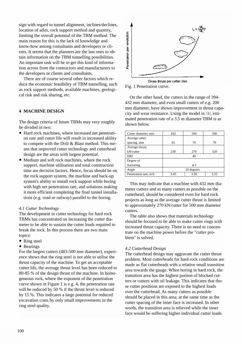
100
sign with regard to tunnel alignment, inclines/declines,location of adits, rock support method and quantity, limiting the overall potential of the TBM method. Themain reason for this is the lack of knowledge andknow-how among consultants and developers or cli-ents. It seems that the planners are the last ones to ob-tain information on the TBM tunnelling possibilities.An important task will be to get this kind of informa-tion across from the contractors and manufacturers tothe developers or clients and consultants.
There are of course several other factors which re-duce the economic feasibility of TBM tunnelling, suchas rock support methods, available machines, geologi-cal risk and risk sharing, etc.
4 MACHINE DESIGN
The design criteria of future TBMs may very roughlybe divided in two:• Hard rock machines, where increased net penetrati-
on rate and cutter life will result in increased ability to compete with the Drill & Blast method. This me-ans that improved cutter technology and cutterhead design are the areas with largest potential.
• Medium and soft rock machines, where the rock support, machine utilisation and total construction time are decisive factors. Hence, focus should be onthe rock support system, the machine and back-up system's ability to install rock support while boring with high net penetration rate, and solutions makingit more efficient completing the final tunnel installa-tions (e.g. road or railway) parallel to the boring.
4.1 Cutter TechnologyThe development in cutter technology for hard rockTBMs has concentrated on increasing the cutter dia-meter to be able to sustain the cutter loads required tobreak the rock. In this process there are two main topics:• Ring steel• BearingsFor the largest cutters (483-500 mm diameter), experi-ence shows that the ring steel is not able to utilise thethrust capacity of the machine. To get an acceptablecutter life, the average thrust level has been reduced to80-85 % of the design thrust of the machine. In homo-geneous rock, where the exponent of the penetrationcurve shown in Figure 1 is e.g. 4, the penetration ratewill be reduced by 50 % if the thrust level is reducedby 15 %. This indicates a large potential for reducedexcavation costs by only small improvements in thering steel quality.
Fig. 1 Penetration curve.
On the other hand, the cutters in the range of 394-432 mm diameter, and even small cutters of e.g. 200mm diameter, have shown improvement in thrust capa-city and wear resistance. Using the model in /1/, esti-mated penetration rate of a 3.5 m diameter TBM is asshown below.
This may indicate that a machine with 432 mm dia-meter cutters and as many cutters as possible on thecutterhead, should be considered even for hard rockprojects as long as the average cutter thrust is limitedto approximately 270 kN/cutter for 500 mm diametercutters.
The table also shows that materials technologyshould be focused to be able to make cutter rings withincreased thrust capacity. There is no need to concen-trate on the machine power before the "cutter pro-blem" is solved.
4.2 Cutterhead DesignThe cutterhead design may aggravate the cutter thrustproblem. Most cutterheads for hard rock conditions aremade as flat cutterheads with a relative small transitionarea towards the gauge. When boring in hard rock, thetransition area has the highest portion of blocked cut-ters or cutters with oil leakage. This indicates that tho-se cutter positions are exposed to the highest loadsover the cutterhead. As many cutters as possibleshould be placed in this area; at the same time as thecutter spacing of the inner face is increased. In otherwords, the transition area is relieved while the innerface would be suffering higher individual cutter loads.
Cutter diameter, mm 432 500 500Average cutterspacing, mm 65 70 70Average thrust, kN/cutter 230 270 320DRI 40Degree offracturing st IAngle 20 degreesPenetration rate, m/h 3.45 3.58 5.25
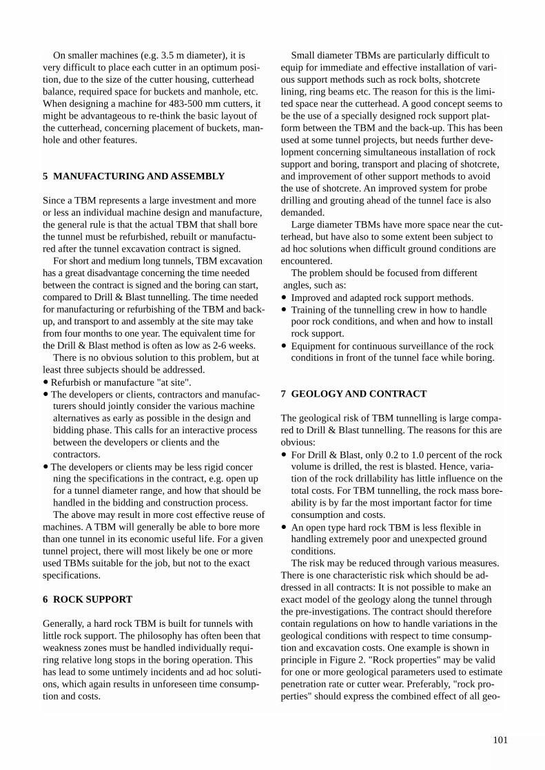
101
On smaller machines (e.g. 3.5 m diameter), it isvery difficult to place each cutter in an optimum posi-tion, due to the size of the cutter housing, cutterheadbalance, required space for buckets and manhole, etc.When designing a machine for 483-500 mm cutters, itmight be advantageous to re-think the basic layout ofthe cutterhead, concerning placement of buckets, man-hole and other features.
5 MANUFACTURING AND ASSEMBLY
Since a TBM represents a large investment and moreor less an individual machine design and manufacture,the general rule is that the actual TBM that shall borethe tunnel must be refurbished, rebuilt or manufactu-red after the tunnel excavation contract is signed.
For short and medium long tunnels, TBM excavationhas a great disadvantage concerning the time neededbetween the contract is signed and the boring can start,compared to Drill & Blast tunnelling. The time neededfor manufacturing or refurbishing of the TBM and back-up, and transport to and assembly at the site may takefrom four months to one year. The equivalent time forthe Drill & Blast method is often as low as 2-6 weeks.
There is no obvious solution to this problem, but at least three subjects should be addressed.• Refurbish or manufacture "at site".• The developers or clients, contractors and manufac-
turers should jointly consider the various machine alternatives as early as possible in the design and bidding phase. This calls for an interactive process between the developers or clients and the contractors.
• The developers or clients may be less rigid concerning the specifications in the contract, e.g. open up for a tunnel diameter range, and how that should be handled in the bidding and construction process.The above may result in more cost effective reuse of
machines. A TBM will generally be able to bore morethan one tunnel in its economic useful life. For a giventunnel project, there will most likely be one or moreused TBMs suitable for the job, but not to the exactspecifications.
6 ROCK SUPPORT
Generally, a hard rock TBM is built for tunnels withlittle rock support. The philosophy has often been thatweakness zones must be handled individually requi-ring relative long stops in the boring operation. Thishas lead to some untimely incidents and ad hoc soluti-ons, which again results in unforeseen time consump-tion and costs.
Small diameter TBMs are particularly difficult toequip for immediate and effective installation of vari-ous support methods such as rock bolts, shotcrete lining, ring beams etc. The reason for this is the limi-ted space near the cutterhead. A good concept seems tobe the use of a specially designed rock support plat-form between the TBM and the back-up. This has beenused at some tunnel projects, but needs further deve-lopment concerning simultaneous installation of rocksupport and boring, transport and placing of shotcrete,and improvement of other support methods to avoidthe use of shotcrete. An improved system for probedrilling and grouting ahead of the tunnel face is alsodemanded.
Large diameter TBMs have more space near the cut-terhead, but have also to some extent been subject toad hoc solutions when difficult ground conditions areencountered.
The problem should be focused from differentangles, such as:
• Improved and adapted rock support methods.• Training of the tunnelling crew in how to handle
poor rock conditions, and when and how to install rock support.
• Equipment for continuous surveillance of the rock conditions in front of the tunnel face while boring.
7 GEOLOGY AND CONTRACT
The geological risk of TBM tunnelling is large compa-red to Drill & Blast tunnelling. The reasons for this areobvious:• For Drill & Blast, only 0.2 to 1.0 percent of the rock
volume is drilled, the rest is blasted. Hence, varia-tion of the rock drillability has little influence on thetotal costs. For TBM tunnelling, the rock mass bore-ability is by far the most important factor for time consumption and costs.
• An open type hard rock TBM is less flexible in handling extremely poor and unexpected groundconditions.The risk may be reduced through various measures.
There is one characteristic risk which should be ad-dressed in all contracts: It is not possible to make anexact model of the geology along the tunnel throughthe pre-investigations. The contract should thereforecontain regulations on how to handle variations in thegeological conditions with respect to time consump-tion and excavation costs. One example is shown inprinciple in Figure 2. "Rock properties" may be validfor one or more geological parameters used to estimatepenetration rate or cutter wear. Preferably, "rock pro-perties" should express the combined effect of all geo-
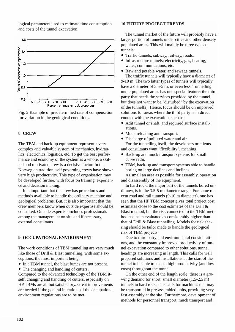
102
logical parameters used to estimate time consumptionand costs of the tunnel excavation.
Fig. 2 Example of predetermined rate of compensationfor variation in the geological conditions.
8 CREW
The TBM and back-up equipment represent a verycomplex and valuable system of mechanics, hydrau-lics, electronics, logistics, etc. To get the best perfor-mance and economy of the system as a whole, a skil-led and motivated crew is a decisive factor. In theNorwegian tradition, self governing crews have shownvery high productivity. This type of organisation maybe developed further, with focus on training, experien-ce and decision making.
It is important that the crew has procedures andmethods available to handle the ordinary machine andgeological problems. But, it is also important that thecrew members know when outside expertise should beconsulted. Outside expertise includes professionalsamong the management on site and if necessary, external consultants.
9 OCCUPATIONAL ENVIRONMENT
The work conditions of TBM tunnelling are very muchlike those of Drill & Blast tunnelling, with some ex-ceptions, the most important being:• In a TBM tunnel, the blast fumes are not present.• The changing and handling of cutters.Compared to the advanced technology of the TBM it-self, changing and handling of cutters, especially onHP TBMs are all but satisfactory. Great improvementsare needed if the general intentions of the occupationalenvironment regulations are to be met.
10 FUTURE PROJECT TRENDS
The tunnel market of the future will probably have alarger portion of tunnels under cities and other denselypopulated areas. This will mainly be three types oftunnels:• Traffic tunnels; subway, railway, roads.• Infrastructure tunnels; electricity, gas, heating,
water, communications, etc.• Raw and potable water, and sewage tunnels.
The traffic tunnels will typically have a diameter of9-10 m. The two latter types of tunnels will typicallyhave a diameter of 3.5-5 m, or even less. Tunnellingunder populated areas has one special feature: the thirdparty that needs the services provided by the tunnel,but does not want to be "disturbed" by the excavationof the tunnel(s). Hence, focus should be on improvedsolutions for areas where the third party is in directcontact with the excavation, such as:• Adit tunnel or shaft, and required surface install-
ations.• Muck reloading and transport.• Discharge of polluted water and air.
For the tunnelling itself, the developers or clients and consultants want "flexibility", meaning:• Back-up and muck transport systems for small
curve radii.• TBM, back-up and transport systems able to handle
boring on large declines and inclines.As small an area as possible for assembly, operation
and disassembly of the equipment.In hard rock, the major part of the tunnels bored un-
til now, is in the 3.5-5 m diameter range. For some re-cent road and rail tunnels (9-10 m diameter), one hasseen that the HP TBM concept gives total project costestimates close to the cost estimates of the Drill &Blast method, but the risk connected to the TBM met-hod has been evaluated as considerably higher thanthat of Drill & Blast tunnelling. Models for risk sha-ring should be tailor made to handle the geologicalrisk of TBM projects.
Due to third party and environmental considerati-ons, and the constantly improved productivity of tun-nel excavation compared to other solutions, tunnelheadings are increasing in length. This calls for wellprepared solutions and installations at the start of thetunnel to be able to keep a high productivity (and lowcosts) throughout the tunnel.
On the other end of the length scale, there is a gro-wing demand for short, small diameter (1.5-2.5 m)tunnels in hard rock. This calls for machines that maybe transported in pre-assembled units, providing veryfast assembly at the site. Furthermore, development ofmethods for personnel transport, muck transport and
103
handling, ventilation, rock support, etc., suited for thesmall cross section are needed.
11 CONCLUSION
The most important step of future TBM technologywill be to develop cutter technology to be able to borehard rock with cutter loads of 320 kN/cutter or more.This will make the TBM tunnelling more competitiveand also increase the tunnelling market as a whole.It is also important that tunnel project planners at anearly stage of the process utilise the special featuresand advantages of hard rock TBM technology to get anoptimum solution for the project as a whole.
LITERATURE
/1/ The University of Trondheim, NTH-Anleggsdrift:Project Report 1-94 HARD ROCK TUNNELBORING, Trondheim 1994, 164 pp.

104
105
THE NORWEGIAN TUNNELLING SOCIETY (NFF)
Due to the topographic and climatic conditions, Norway has a large hydropower potential. Thedevelopment of hydropower plants has resulted in the construction of 4,000 km of tunnels and200 underground power stations.High mountains, deep valleys and fjords, as well as a widely dispersed population, have alwayspresented considerable challenges for communication and transport systems. As of today, thereare over 850 road tunnels and more than 700 railway tunnels in the country.
The more recent developments include excavation of underground rock caverns for public use,storage caverns for oil and gas, shore approach tunnels for the transport of oil and gas from theNorth Sea, sub sea road tunnels for crossing fjords, storage caverns for food and drinking water,sewage treatment plants etc.
Rock excavation and tunnelling are vital elements in the development of the infrastructure. The Norwegian Tunnelling Society (NFF), funded in 1964, provides a forum for the exchangeof information and experience within these fields.
NFF is the organiser of the Norwegian Rock Excavation and Tunnelling Conference. Staged annually since 1963, the conference assembles from 600 to 800 participants from the miningand tunnelling industry in all the Nordic countries.
Internationally, the Norwegian Tunnelling Society co-ordinates and promotes the presentationof Norwegian expertise and resources abroad. The Society has issued a number of publicationsin English on tunnelling technology.
The Norwegian Tunnelling Society is member of the International Tunnelling Association (ITA)and the European Federation of Explosives Engineers (EFEE). NFF is an open society. Themembers are Scientific Institutes, Universities, Public Agencies, Private Companies and indivi-dual members from all walks of the profession.
The society structure is led by a Board of Directors, and has the following five permanent com-mittees: Economy and Public relations, International Activities, Research & Development,Professional matters and the Rock Excavation and Tunnelling Conference. The society has aSecretariat General that deals with technical matters and the operation of the society (e-mail:[email protected]) and also a Secretariat to organise Seminars and Conferences (e-mail:[email protected]).
NORWEGIAN TUNNELLING SOCIETY
Appendix A
106
NFF’s International Support Group Appendix B
General Contractors
NCC Eeg-Henriksen Anlegg A/SP. O. Box 454 SentrumN-0104 OSLO
Nocon ASAP. O. Box 1175 SentrumN-0107 OSLO
Selmer ASAP. O. Box 1175 SentrumN-0107 OSLO
Statkraft Anlegg ASP. O. Box 231N-1322 HØVIK
Veidekke ASA Div. AnleggP. O. Box 1870 VikaN-0124 OSLO
Consulting and Engineering firms, Research Institutes
Fortifikasjon A/SP. O. Box 4363 TorshovN-0402 OSLO
Grøner ASP. O. Box 400N-1324 LYSAKER
Norconsult ASVestfjordgt. 4N-1300 SANDVIKA
Norwegian Geotechnical InstituteP. O. Box 3930 Ulleval HagebyN-0806 OSLO
Noteby A/SP. O. Box 265 SkøyenN-0212 OSLO
NVK ASP. O. Box 280N-1401 SKI
O. T. Blindheim ASKjopmannsgt. 61N-7011 TRONDHEIM
SINTEF Civil and Environmental EngineeringRock and Mineral EngineeringN-7034 TRONDHEIM
Statkraft Engineering ASP. O. Box 191N-1322 HØVIK
107
Manufacturers andTrading Firms
Andersen Mek. Verksted ASP. O. Box 194N-4401 FLEKKEFJORD
Atlas Copco A/SP. O. Box 323N-1401 SKI
DYNO Industries ASAP. O. Box 614N-3412 LIERSTRANDA
Fundia Bygg A/SP. O. Box 4224 TorshovN-0401 OSLO
Public Corporations, GovernmentAuthorities and Owner Companies
The Norwegian Civil Aviation AdministrationP. O. Box 8124 DEPN-0032 OSLO
The Public Roads AdministrationP. O. Box 8142 DEPN-0033 OSLO
Norsk Hydro ASAN-0240 OSLO
Protan A/SP. O. Box 420N-3002 DRAMMEN
Rescon A/SVallsetvn. 6N-2120 SAGSTUA
Stein Narvestad A/SP. O. Box 2412 SolliN-0204 OSLO
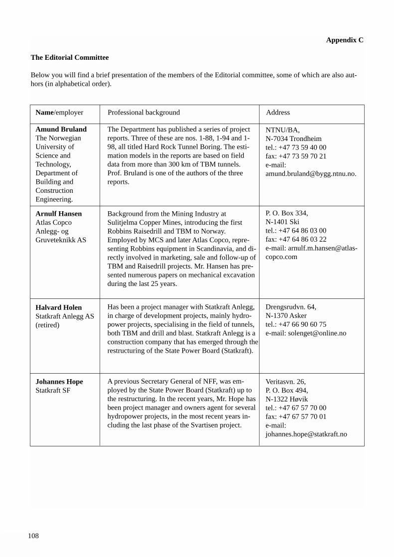
108
Appendix C
The Editorial Committee
Below you will find a brief presentation of the members of the Editorial committee, some of which are also aut-hors (in alphabetical order).
Name/employer Professional background Address
Amund BrulandThe NorwegianUniversity ofScience andTechnology,Department ofBuilding andConstructionEngineering.
The Department has published a series of projectreports. Three of these are nos. 1-88, 1-94 and 1-98, all titled Hard Rock Tunnel Boring. The esti-mation models in the reports are based on fielddata from more than 300 km of TBM tunnels.Prof. Bruland is one of the authors of the three reports.
NTNU/BA, N-7034 Trondheimtel.: +47 73 59 40 00fax: +47 73 59 70 21e-mail:[email protected].
Arnulf HansenAtlas CopcoAnlegg- ogGruveteknikk AS
Background from the Mining Industry atSulitjelma Copper Mines, introducing the firstRobbins Raisedrill and TBM to Norway.Employed by MCS and later Atlas Copco, repre-senting Robbins equipment in Scandinavia, and di-rectly involved in marketing, sale and follow-up ofTBM and Raisedrill projects. Mr. Hansen has pre-sented numerous papers on mechanical excavationduring the last 25 years.
P. O. Box 334,N-1401 Skitel.: +47 64 86 03 00fax: +47 64 86 03 22e-mail: [email protected]
Halvard HolenStatkraft Anlegg AS(retired)
Has been a project manager with Statkraft Anlegg,in charge of development projects, mainly hydro-power projects, specialising in the field of tunnels,both TBM and drill and blast. Statkraft Anlegg is aconstruction company that has emerged through therestructuring of the State Power Board (Statkraft).
Drengsrudvn. 64,N-1370 Askertel.: +47 66 90 60 75e-mail: [email protected]
Johannes HopeStatkraft SF
A previous Secretary General of NFF, was em-ployed by the State Power Board (Statkraft) up tothe restructuring. In the recent years, Mr. Hope hasbeen project manager and owners agent for severalhydropower projects, in the most recent years in-cluding the last phase of the Svartisen project.
Veritasvn. 26, P. O. Box 494, N-1322 Høviktel.: +47 67 57 70 00fax: +47 67 57 70 01e-mail: [email protected]
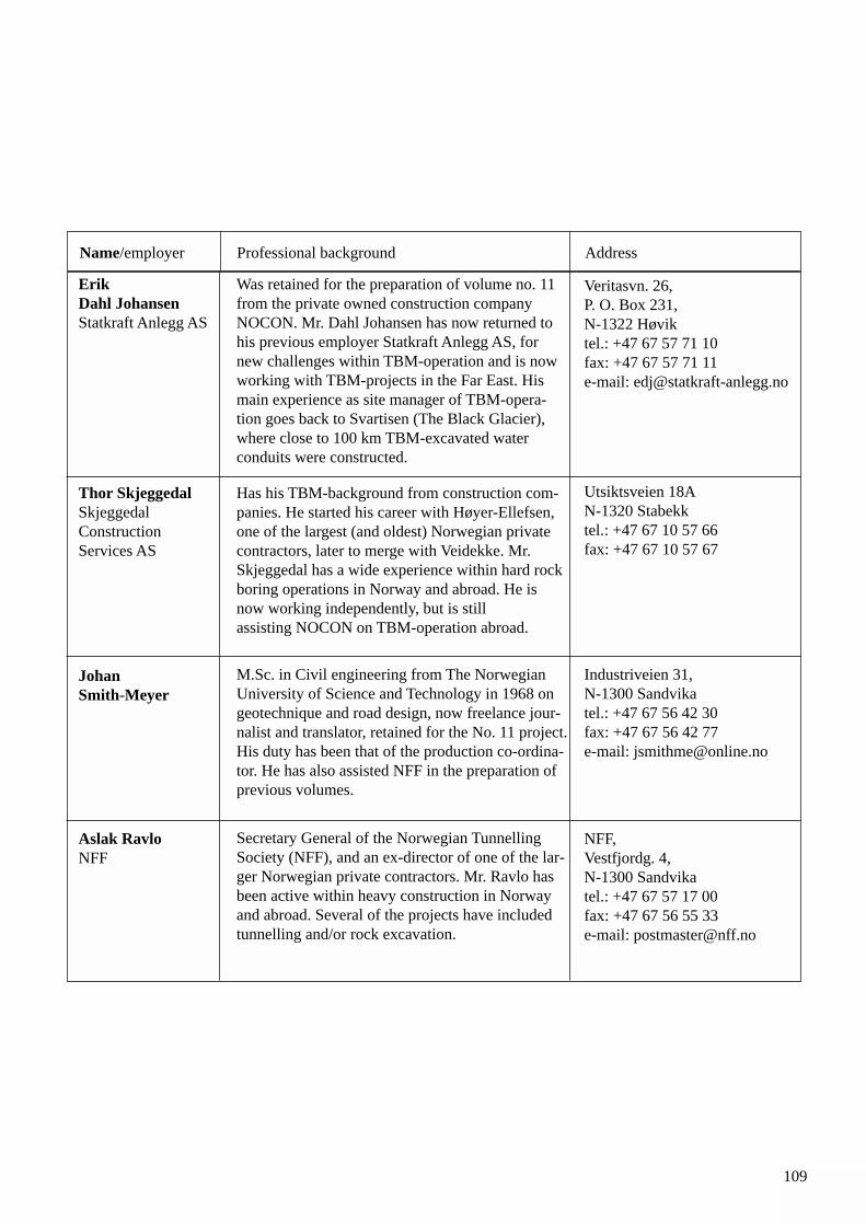
109
Erik Dahl Johansen Statkraft Anlegg AS
Was retained for the preparation of volume no. 11from the private owned construction companyNOCON. Mr. Dahl Johansen has now returned tohis previous employer Statkraft Anlegg AS, fornew challenges within TBM-operation and is nowworking with TBM-projects in the Far East. Hismain experience as site manager of TBM-opera-tion goes back to Svartisen (The Black Glacier),where close to 100 km TBM-excavated waterconduits were constructed.
Veritasvn. 26,P. O. Box 231, N-1322 Høviktel.: +47 67 57 71 10fax: +47 67 57 71 11e-mail: [email protected]
Thor SkjeggedalSkjeggedalConstructionServices AS
Has his TBM-background from construction com-panies. He started his career with Høyer-Ellefsen,one of the largest (and oldest) Norwegian privatecontractors, later to merge with Veidekke. Mr.Skjeggedal has a wide experience within hard rockboring operations in Norway and abroad. He isnow working independently, but is stillassisting NOCON on TBM-operation abroad.
Utsiktsveien 18AN-1320 Stabekktel.: +47 67 10 57 66fax: +47 67 10 57 67
Johan Smith-Meyer
M.Sc. in Civil engineering from The NorwegianUniversity of Science and Technology in 1968 ongeotechnique and road design, now freelance jour-nalist and translator, retained for the No. 11 project.His duty has been that of the production co-ordina-tor. He has also assisted NFF in the preparation ofprevious volumes.
Industriveien 31, N-1300 Sandvikatel.: +47 67 56 42 30fax: +47 67 56 42 77e-mail: [email protected]
Aslak Ravlo NFF
Secretary General of the Norwegian TunnellingSociety (NFF), and an ex-director of one of the lar-ger Norwegian private contractors. Mr. Ravlo hasbeen active within heavy construction in Norwayand abroad. Several of the projects have includedtunnelling and/or rock excavation.
NFF,Vestfjordg. 4, N-1300 Sandvikatel.: +47 67 57 17 00fax: +47 67 56 55 33e-mail: [email protected]
Name/employer Professional background Address
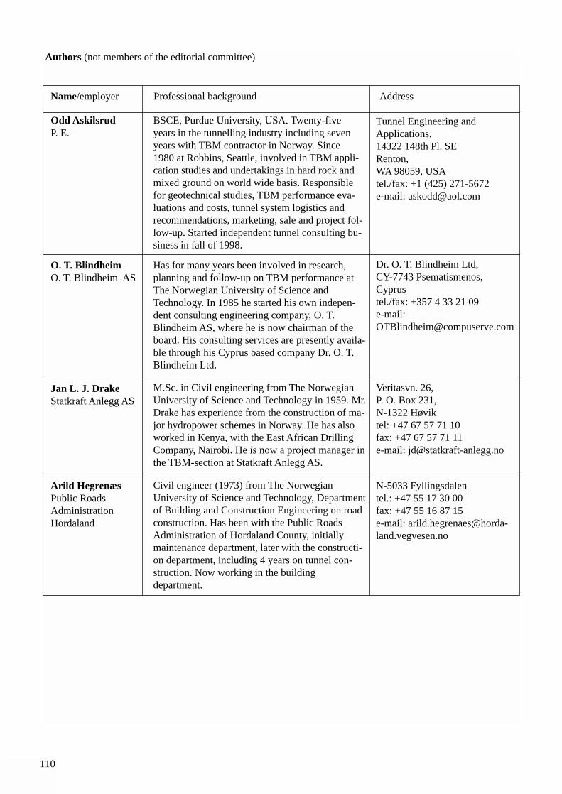
110
Name/employer Professional background Address
Odd AskilsrudP. E.
BSCE, Purdue University, USA. Twenty-fiveyears in the tunnelling industry including sevenyears with TBM contractor in Norway. Since1980 at Robbins, Seattle, involved in TBM appli-cation studies and undertakings in hard rock andmixed ground on world wide basis. Responsiblefor geotechnical studies, TBM performance eva-luations and costs, tunnel system logistics andrecommendations, marketing, sale and project fol-low-up. Started independent tunnel consulting bu-siness in fall of 1998.
Tunnel Engineering andApplications,14322 148th Pl. SERenton, WA 98059, USAtel./fax: +1 (425) 271-5672e-mail: [email protected]
O. T. BlindheimO. T. Blindheim AS
Has for many years been involved in research,planning and follow-up on TBM performance atThe Norwegian University of Science andTechnology. In 1985 he started his own indepen-dent consulting engineering company, O. T.Blindheim AS, where he is now chairman of theboard. His consulting services are presently availa-ble through his Cyprus based company Dr. O. T.Blindheim Ltd.
Dr. O. T. Blindheim Ltd, CY-7743 Psematismenos,Cyprustel./fax: +357 4 33 21 09e-mail:[email protected]
Jan L. J. DrakeStatkraft Anlegg AS
M.Sc. in Civil engineering from The NorwegianUniversity of Science and Technology in 1959. Mr.Drake has experience from the construction of ma-jor hydropower schemes in Norway. He has alsoworked in Kenya, with the East African DrillingCompany, Nairobi. He is now a project manager inthe TBM-section at Statkraft Anlegg AS.
Veritasvn. 26,P. O. Box 231, N-1322 Høviktel: +47 67 57 71 10fax: +47 67 57 71 11e-mail: [email protected]
Arild HegrenæsPublic RoadsAdministrationHordaland
Civil engineer (1973) from The NorwegianUniversity of Science and Technology, Departmentof Building and Construction Engineering on roadconstruction. Has been with the Public RoadsAdministration of Hordaland County, initiallymaintenance department, later with the constructi-on department, including 4 years on tunnel con-struction. Now working in the building department.
N-5033 Fyllingsdalen tel.: +47 55 17 30 00fax: +47 55 16 87 15e-mail: [email protected]
Authors (not members of the editorial committee)
111
Karl GunnarHolterSelmer ASA
Geotechnical engineer M.Sc., now working withthe contractor Selmer ASA, currently at the PontVentoux hydropower scheme in the Italian Alps(joint venture with Veidekke ASA) as site geo-technical engineer during TBM excavation ofthree hydropower tunnels. Prior experience withemphasis on caverns in hard rock and subsea roadtunnels, at design stage as well as decision assis-tance on site during construction.
P. O. Box 1175 Sentrum, N-0107 Oslotel.: +47 22 03 06 00fax: +47 22 20 88 30e-mail: [email protected]
SteinarJohannessenScandinavian RockGroup AS
Technical Engineer in 1976. Working with theSvartevann & Skibotn Power Company. CivilEngineer from the Norwegian University ofScience and Technology in 1982. TBM Tunnellingexperience with Merkraft, a JV to construct tun-nels for the Meraker Power Project. ProjectManager with Scandinavian Rock Group AS onthe Romeriksporten, a 13 km long tunnel for theAirport Express Train to the new OsloGardermoen Airport. Now manag. director for thecompany.
Scandinavian Rock Group AS. P. O. Boks 6621 EtterstadN-0607 Oslotel.: +47 22 08 00 00fax: +47 22 08 00 01e-mail:[email protected]
Tom MyranSINTEF Civil andEnvironmentalEngineering
Professor, Mining Engineering, Dept. of geologyand mineral resources engineering, NorwegianUniversity of Science and Technology. SeniorResearch Scientist, SINTEF (The Foundation forScientific and Industrial Research at the NorwegianUniversity of Science and Technology), Civil andEnvironmental Engineering. Mr. Myran has written40 papers, including two books, on mine ventilati-on/mine environment, among which 10 are with co-author(s).
SINTEF, Div. of Rock andMineral Engineering,N-7034 Trondheimtel.: +47 73 59 31 76fax: +47 73 59 47 78e-mail: [email protected]
Arne MyrvangThe NorwegianUniversity ofScience andTechnology,Department ofGeology and RockEngineering
Professor of Rock Mechanics. More than 30 yearsof experience within applied rock mechanics in civil and mining engineering inNorway and abroad.
The Norwegian University ofScience and Technology, N-7034 Trondheimtel.: +47 73 59 48 48fax: +47 73 59 47 78e-mail:[email protected]
Name/employer Professional background Address
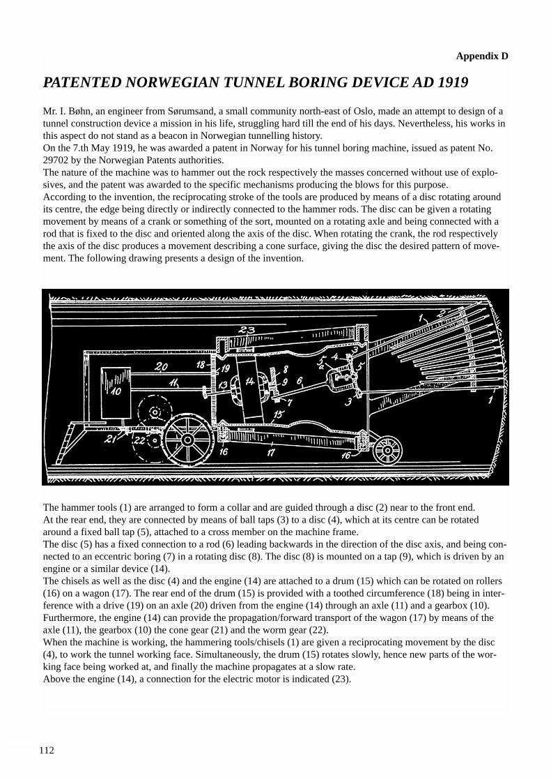
112
Appendix D
PATENTED NORWEGIAN TUNNEL BORING DEVICE AD 1919
Mr. I. Bøhn, an engineer from Sørumsand, a small community north-east of Oslo, made an attempt to design of atunnel construction device a mission in his life, struggling hard till the end of his days. Nevertheless, his works inthis aspect do not stand as a beacon in Norwegian tunnelling history. On the 7.th May 1919, he was awarded a patent in Norway for his tunnel boring machine, issued as patent No.29702 by the Norwegian Patents authorities.The nature of the machine was to hammer out the rock respectively the masses concerned without use of explo-sives, and the patent was awarded to the specific mechanisms producing the blows for this purpose.According to the invention, the reciprocating stroke of the tools are produced by means of a disc rotating aroundits centre, the edge being directly or indirectly connected to the hammer rods. The disc can be given a rotatingmovement by means of a crank or something of the sort, mounted on a rotating axle and being connected with arod that is fixed to the disc and oriented along the axis of the disc. When rotating the crank, the rod respectivelythe axis of the disc produces a movement describing a cone surface, giving the disc the desired pattern of move-ment. The following drawing presents a design of the invention.
The hammer tools (1) are arranged to form a collar and are guided through a disc (2) near to the front end.At the rear end, they are connected by means of ball taps (3) to a disc (4), which at its centre can be rotatedaround a fixed ball tap (5), attached to a cross member on the machine frame.The disc (5) has a fixed connection to a rod (6) leading backwards in the direction of the disc axis, and being con-nected to an eccentric boring (7) in a rotating disc (8). The disc (8) is mounted on a tap (9), which is driven by anengine or a similar device (14).The chisels as well as the disc (4) and the engine (14) are attached to a drum (15) which can be rotated on rollers(16) on a wagon (17). The rear end of the drum (15) is provided with a toothed circumference (18) being in inter-ference with a drive (19) on an axle (20) driven from the engine (14) through an axle (11) and a gearbox (10).Furthermore, the engine (14) can provide the propagation/forward transport of the wagon (17) by means of theaxle (11), the gearbox (10) the cone gear (21) and the worm gear (22).When the machine is working, the hammering tools/chisels (1) are given a reciprocating movement by the disc(4), to work the tunnel working face. Simultaneously, the drum (15) rotates slowly, hence new parts of the wor-king face being worked at, and finally the machine propagates at a slow rate.Above the engine (14), a connection for the electric motor is indicated (23).
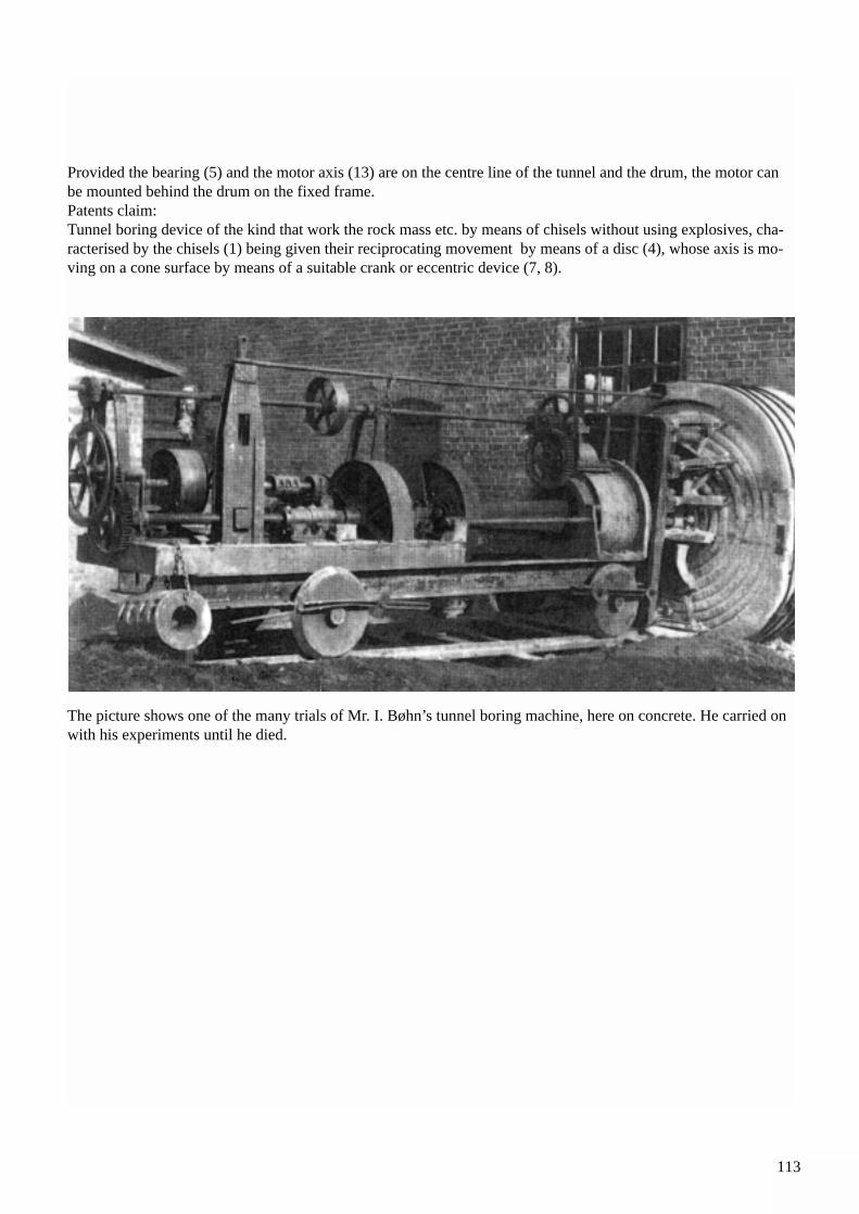
113
Provided the bearing (5) and the motor axis (13) are on the centre line of the tunnel and the drum, the motor canbe mounted behind the drum on the fixed frame.Patents claim:Tunnel boring device of the kind that work the rock mass etc. by means of chisels without using explosives, cha-racterised by the chisels (1) being given their reciprocating movement by means of a disc (4), whose axis is mo-ving on a cone surface by means of a suitable crank or eccentric device (7, 8).
The picture shows one of the many trials of Mr. I. Bøhn’s tunnel boring machine, here on concrete. He carried onwith his experiments until he died.
114
Appendix E
Publications and Videos available from Norwegian Tunnelling Society (NFF)
ORDER FORM
Please mail or fax this order form to: NORWEGIAN TUNNELLING SOCIETY (NFF)P. O. Box 2312 SolliN-0251 Oslo, NorwayTelefax: + 47 22 94 75 02e-mail: [email protected]
Application for membership in the Norwegian Tunnelling Society (NFF)
* I apply for individual membership. Language: English NOK 150 per year* Jeg søker om personlig medlemskap. Språk: Norsk NOK 100 pr. år* My company applies for corporate membership. Language: English NOK 1,500 per year* Vi søker firmamedlemskap. Språk: Norsk NOK 1 500 pr. år* Vi søker om firma- og støttemedlemskap for internasjonal virksomhet NOK 7 500 pr. år
Name:
Company:
Address:
Please debit credit card number:
Card holders name:
Card holders address:
Publication No. 1 Norwegian Hard Rock Tunnelling (104 pp) 100Publication No. 2 Norwegian Tunnelling Technology (84 pp) 100Publication No. 3 Norwegian Hydropower Tunnelling (119 pp) 100Publication No. 4 Norwegian Road Tunnelling (172 pp) 50Publication No. 5 Norwegian Tunnelling Today (135 pp) 100Publication No. 6 Geology of Norway (4 pp. and geol. map) 100Publication No. 7 Norwegian Tunnels & Tunnelling (130 pp) 50Publication No. 8 Norwegian Subsea Tunnelling (100 pp) 100Publication No. 9 Norwegian Underground Storage (103 pp) 100Publication No. 10 Norwegian Urban Tunnelling (86 pp) 100Publication No. 11 Norwegian TBM Tunnelling (118 pp) 100Gjovik Olympic Mountain Hall Design & Construction (32 pp.) 60Gjovik Olympic Mountain Hall Video (13 minutes) 300 1)Video system preferred: * PAL-VHS 1) * NTSC 2) * SECAM 3) 600 2) & 3)Tunnelling in Norway ‘98 Video (10 minutes) PAL-VHS 300
Price in NOK(Postage incl.)
Qty.
Visa ❑ Diners ❑ Master Card ❑ American Express ❑
Expiry date
Place and date Signature
Please mail or fax this form to:
Norwegian Tunnelling Society (NFF)
P. O. Box 2312 Solli
N-0201 Oslo, Norway
e-mail: [email protected]
NORWEGIANTBM TUNNELLING
PUBLICATION NO. 11
NORWEGIAN SOIL AND ROCK ENGINEERING ASSOCIATION
PUBLICATION NO. 11NO
RWEG
IAN TBM TUNNELLING
![TBM 렌탈솔루션 - cafe24mrrental.cafe24.com/tbm/tbmrs_service_introduction.pdf · 01. TBM 렌탈솔루션소개 [이미지출처: 효성에프엠에스뉴스레터(2019.01.28)]](https://img.pdfslide.net/doc/110x75/5ece13d36c14a753b559968e/tbm-eoefe-01-tbm-eoefeoeeoe-eoe-ee20190128.jpg)