Embed Size (px)
Citation preview

Notes on Use of 24-V Controller by Grounding Its Power Supply at Positive Terminal

Please Read Before Use Thank you for purchasing our product. This Operation Manual explains the grounding methods of this product, among others, providing the information you need to know to use the product safely. Before using the product, be sure to read this manual and fully understand the contents explained herein to ensure safe use of the product. The CD that comes with the product contains operation manuals for IAI products. When using the product, refer to the necessary portions of the applicable operation manual by printing them out or displaying them on a PC. After reading the Operation Manual, keep it in a convenient place so that whoever is handling this product can reference it quickly when necessary.
[Important] The product cannot be operated in any way unless expressly specified in this Operation Manual. IAI
shall assume no responsibility for the outcome of any operation not specified herein. Information contained in this Operation Manual is subject to change without notice for the purpose of
product improvement. If you have any question or comment regarding the content of this manual, please contact the IAI
sales office near you. Using or copying all or part of this Operation Manual without permission is prohibited. The company names, names of products and trademarks of each company shown in the sentences
are registered trademarks.

Table of Contents
1. Overview.............................................................................................................................1
2. Examples of Problem .........................................................................................................1
3. Countermeasures ...............................................................................................................5
4. Connection Example ........................................................................................................10
5. Whether or not each teaching pendant can be used ........................................................14
6. Change History.................................................................................................................16
1
Teaching pendant SIO connector
SIO connector housing
Controller ERC2, RCP2, RCA and RCS-C/E 24-V power supply
The GND and shield are short-circuited inside the teaching pendant. (RCM-T/TD, CON-T/TD/PT/PD/PG and SEP-PT)
Short- circuiting
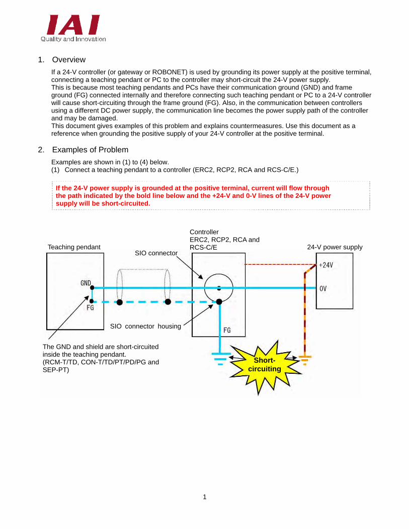
1. Overview
If a 24-V controller (or gateway or ROBONET) is used by grounding its power supply at the positive terminal, connecting a teaching pendant or PC to the controller may short-circuit the 24-V power supply. This is because most teaching pendants and PCs have their communication ground (GND) and frame ground (FG) connected internally and therefore connecting such teaching pendant or PC to a 24-V controller will cause short-circuiting through the frame ground (FG). Also, in the communication between controllers using a different DC power supply, the communication line becomes the power supply path of the controller and may be damaged. This document gives examples of this problem and explains countermeasures. Use this document as a reference when grounding the positive supply of your 24-V controller at the positive terminal.
2. Examples of Problem
Examples are shown in (1) to (4) below. (1) Connect a teaching pendant to a controller (ERC2, RCP2, RCA and RCS-C/E.)
If the 24-V power supply is grounded at the positive terminal, current will flow through the path indicated by the bold line below and the +24-V and 0-V lines of the 24-V power supply will be short-circuited.
2
PC
Communication cable for PC software (Cable supplied with the PC software RCM-101-USB)
Short- circuiting
Controller Conversion supply
adapter
24-V power supply
The GND and FG are short-circuited in the PC.
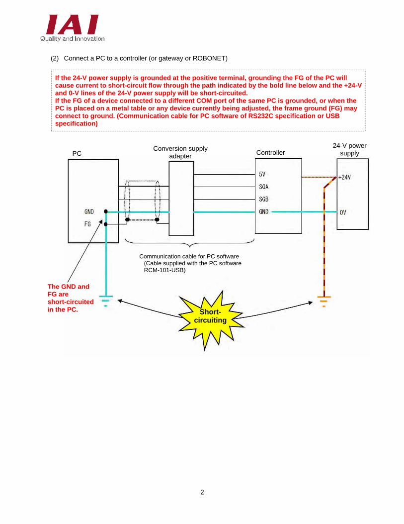
(2) Connect a PC to a controller (or gateway or ROBONET)
If the 24-V power supply is grounded at the positive terminal, grounding the FG of the PC will cause current to short-circuit flow through the path indicated by the bold line below and the +24-V and 0-V lines of the 24-V power supply will be short-circuited. If the FG of a device connected to a different COM port of the same PC is grounded, or when the PC is placed on a metal table or any device currently being adjusted, the frame ground (FG) may connect to ground. (Communication cable for PC software of RS232C specification or USB specification)
3
PC
Short- circuiting
Controller SIO converter
24-V power supply
The GND and FG are short-circuited in the PC.
Controller link cable CB-RCB-CTL
Controller
RS232C communication
RS485 communication
Shield of RS232C cross cable (commercial product)
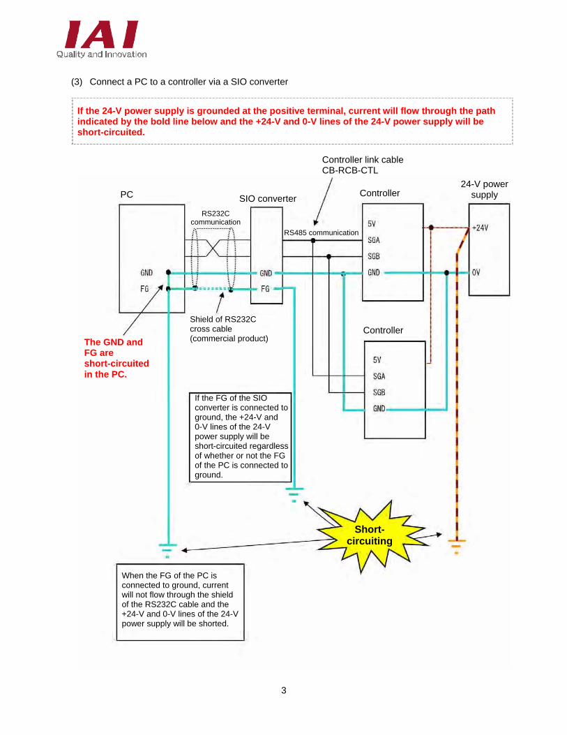
When the FG of the PC is connected to ground, current will not flow through the shield of the RS232C cable and the +24-V and 0-V lines of the 24-V power supply will be shorted.
If the FG of the SIO converter is connected to ground, the +24-V and 0-V lines of the 24-V power supply will be short-circuited regardless of whether or not the FG of the PC is connected to ground.
(3) Connect a PC to a controller via a SIO converter
If the 24-V power supply is grounded at the positive terminal, current will flow through the path indicated by the bold line below and the +24-V and 0-V lines of the 24-V power supply will be short-circuited.
4
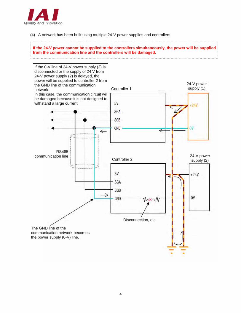
Controller 1 24-V power supply (1)
24-V power supply (2) Controller 2
RS485 communication line
The GND line of the communication network becomes the power supply (0-V) line.
Disconnection, etc.
(4) A network has been built using multiple 24-V power supplies and controllers
If the 24-V power cannot be supplied to the controllers simultaneously, the power will be supplied from the communication line and the controllers will be damaged.
If the 0-V line of 24-V power supply (2) is disconnected or the supply of 24 V from 24-V power supply (2) is delayed, the power will be supplied to controller 2 from the GND line of the communication network. In this case, the communication circuit will be damaged because it is not designed to withstand a large current.
5
Controller FRC2, RCP2, RCA and RCS-C/E SIO converter
24-V power supply
RS485 communication
Controller link cable CB-RCB-CTL
Teaching pendant
The GND and shield are short-circuited inside the teaching pendant.
Do not connect the FG terminal to ground.
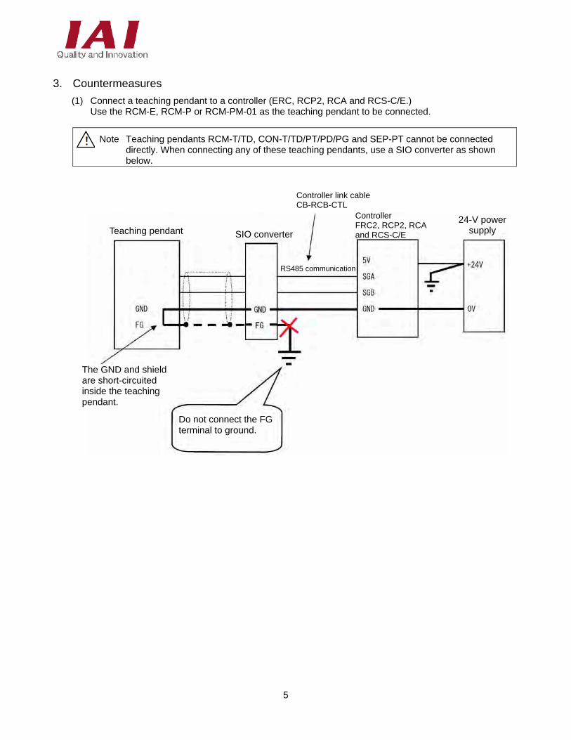
3. Countermeasures
(1) Connect a teaching pendant to a controller (ERC, RCP2, RCA and RCS-C/E.) Use the RCM-E, RCM-P or RCM-PM-01 as the teaching pendant to be connected.
Note Teaching pendants RCM-T/TD, CON-T/TD/PT/PD/PG and SEP-PT cannot be connected directly. When connecting any of these teaching pendants, use a SIO converter as shown below.
6
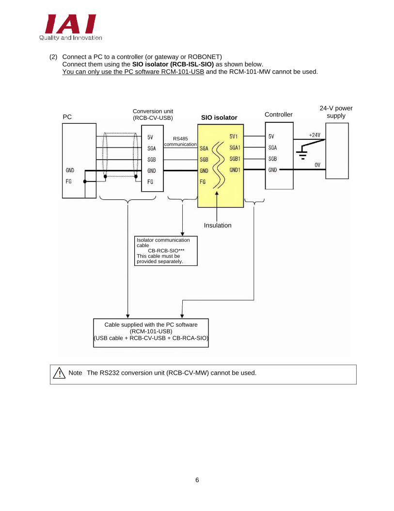
(2) Connect a PC to a controller (or gateway or ROBONET)
Connect them using the SIO isolator (RCB-ISL-SIO) as shown below. You can only use the PC software RCM-101-USB and the RCM-101-MW cannot be used.
Note The RS232 conversion unit (RCB-CV-MW) cannot be used.
Conversion unit(RCB-CV-USB) SIO isolator Controller
24-V power supply PC
RS485 communication
Insulation
Isolator communicationcable
CB-RCB-SIO*** This cable must be provided separately.
Cable supplied with the PC software (RCM-101-USB)
(USB cable + RCB-CV-USB + CB-RCA-SIO)
7
SIO converter Controller 24-V power
supply PC
RS485 communication
Controller link cable CB-RCB-CTL
RS232C communication
The GND and FG are short-circuited in the PC
Controller
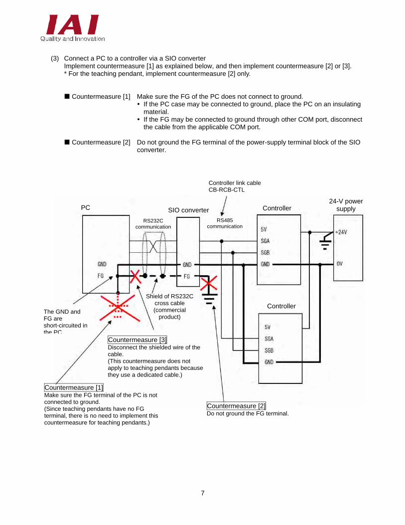
Countermeasure [1] Make sure the FG terminal of the PC is not connected to ground. (Since teaching pendants have no FG terminal, there is no need to implement this countermeasure for teaching pendants.)
Countermeasure [3] Disconnect the shielded wire of the cable. (This countermeasure does not apply to teaching pendants because they use a dedicated cable.)
Countermeasure [2] Do not ground the FG terminal.
Shield of RS232Ccross cable (commercial
product)
(3) Connect a PC to a controller via a SIO converter
Implement countermeasure [1] as explained below, and then implement countermeasure [2] or [3]. * For the teaching pendant, implement countermeasure [2] only.
Countermeasure [1] Make sure the FG of the PC does not connect to ground. If the PC case may be connected to ground, place the PC on an insulating
material. If the FG may be connected to ground through other COM port, disconnect
the cable from the applicable COM port.
Countermeasure [2] Do not ground the FG terminal of the power-supply terminal block of the SIO converter.
8
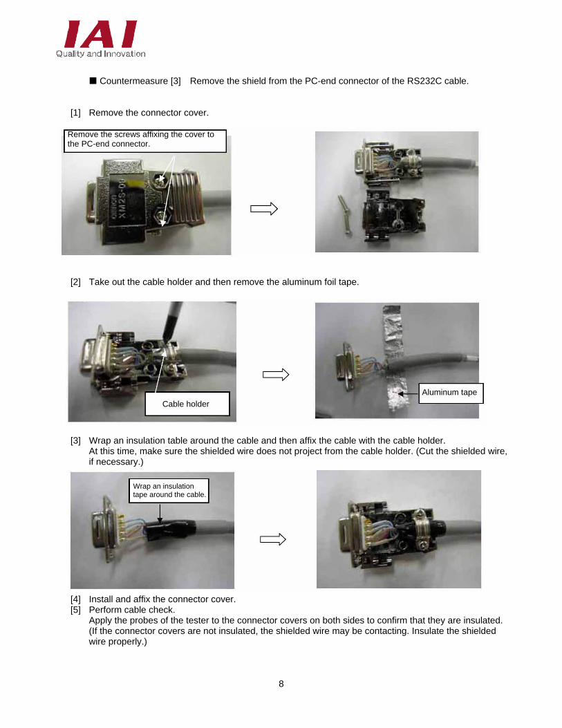
Countermeasure [3] Remove the shield from the PC-end connector of the RS232C cable.
[1] Remove the connector cover.
[2] Take out the cable holder and then remove the aluminum foil tape.
[3] Wrap an insulation table around the cable and then affix the cable with the cable holder. At this time, make sure the shielded wire does not project from the cable holder. (Cut the shielded wire, if necessary.)
[4] Install and affix the connector cover. [5] Perform cable check.
Apply the probes of the tester to the connector covers on both sides to confirm that they are insulated. (If the connector covers are not insulated, the shielded wire may be contacting. Insulate the shielded wire properly.)
Remove the screws affixing the cover to the PC-end connector.
Cable holder
Aluminum tape
Wrap an insulation tape around the cable.
9
Insulation
Controller 1 24-V power supply (1)
SIO isolator
Controller 2 24-V power supply (2)
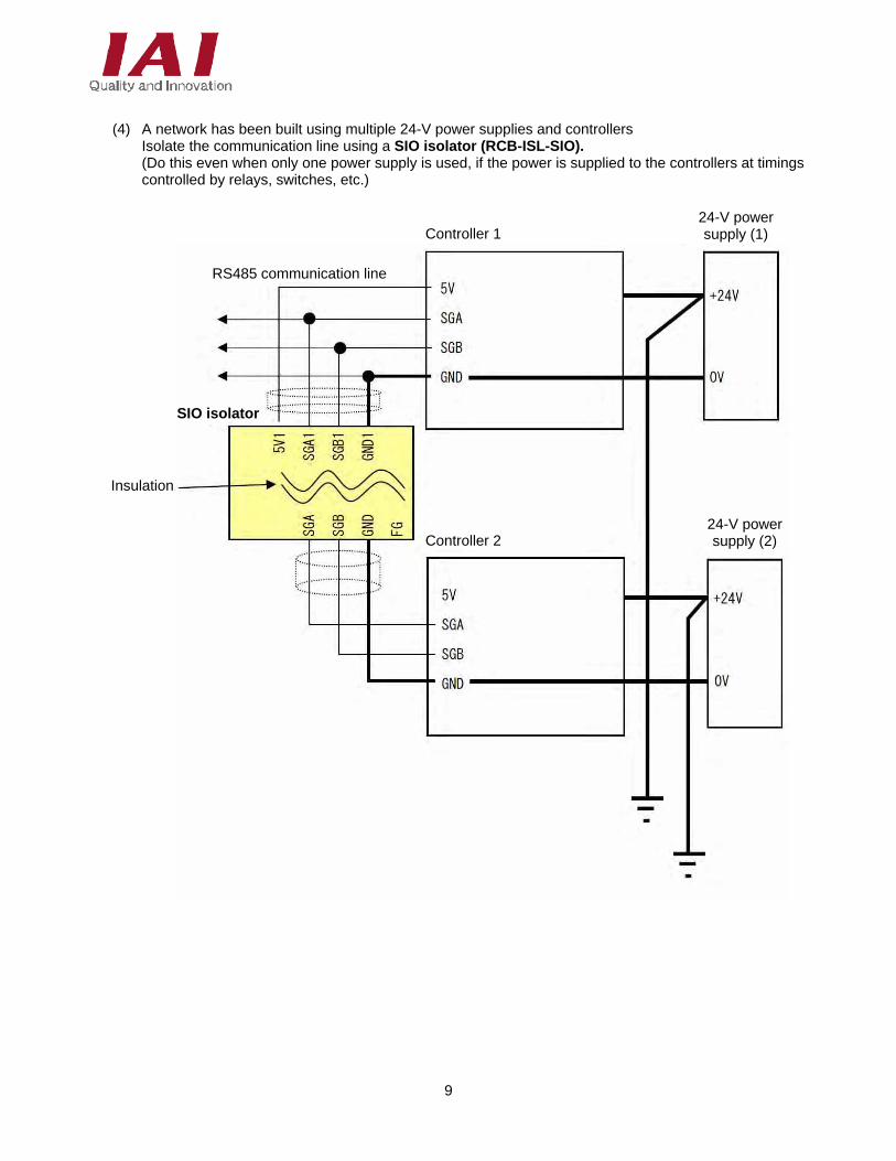
(4) A network has been built using multiple 24-V power supplies and controllers
Isolate the communication line using a SIO isolator (RCB-ISL-SIO). (Do this even when only one power supply is used, if the power is supplied to the controllers at timings controlled by relays, switches, etc.)
RS485 communication line
10
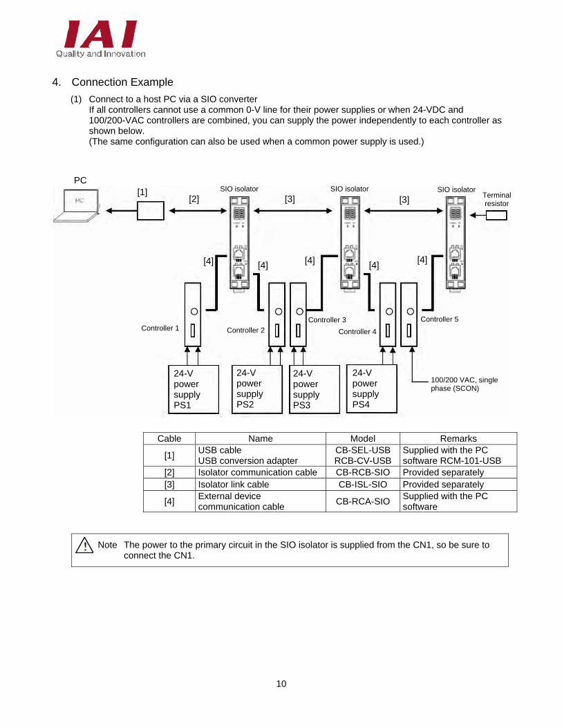
4. Connection Example
(1) Connect to a host PC via a SIO converter If all controllers cannot use a common 0-V line for their power supplies or when 24-VDC and 100/200-VAC controllers are combined, you can supply the power independently to each controller as shown below. (The same configuration can also be used when a common power supply is used.)
Cable Name Model Remarks
[1] USB cable USB conversion adapter
CB-SEL-USB RCB-CV-USB
Supplied with the PC software RCM-101-USB
[2] Isolator communication cable CB-RCB-SIO Provided separately [3] Isolator link cable CB-ISL-SIO Provided separately
[4] External device communication cable
CB-RCA-SIO Supplied with the PC software
Note The power to the primary circuit in the SIO isolator is supplied from the CN1, so be sure to connect the CN1.
PC [1]
[2] [3] SIO isolator SIO isolator SIO isolator
[3]
Controller 1 Controller 2
Controller 3
Controller 4
Controller 5
[4] [4] [4] [4] [4]
Terminal resistor
100/200 VAC, single phase (SCON)
24-V power supply PS1
24-V power supply PS2
24-V power supply PS3
24-V power supply PS4
11
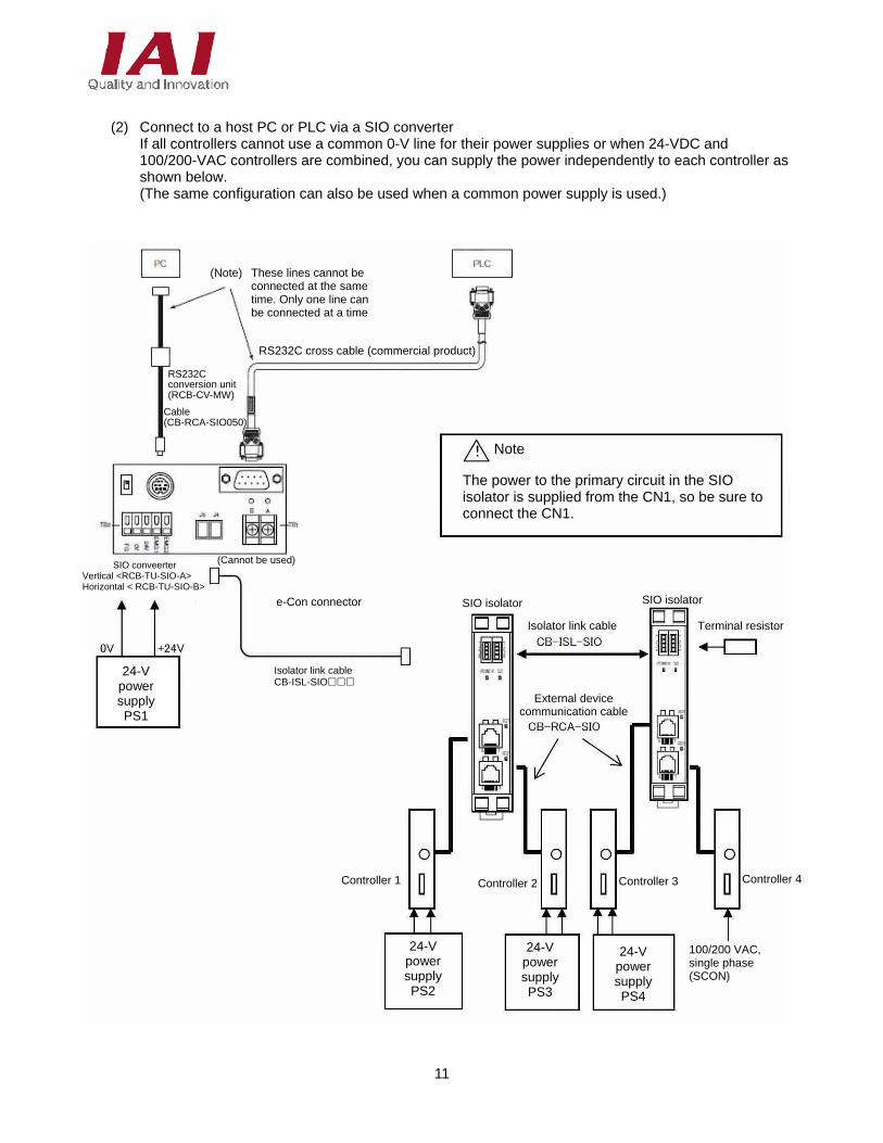
(2) Connect to a host PC or PLC via a SIO converter
If all controllers cannot use a common 0-V line for their power supplies or when 24-VDC and 100/200-VAC controllers are combined, you can supply the power independently to each controller as shown below. (The same configuration can also be used when a common power supply is used.)
(Note) These lines cannot be connected at the same time. Only one line can be connected at a time
RS232C cross cable (commercial product)
The power to the primary circuit in the SIO isolator is supplied from the CN1, so be sure to connect the CN1.
Note
(Cannot be used) SIO conveerter Vertical <RCB-TU-SIO-A> Horizontal < RCB-TU-SIO-B>
Isolator link cable CB-ISL-SIO
SIO isolator
24-V power supply PS1
24-V power supply PS2
24-V power supply PS3
24-V power supply PS4
100/200 VAC, single phase (SCON)
Controller 1 Controller 2 Controller 3 Controller 4
External device communication cable
Isolator link cable
SIO isolator
Terminal resistor
RS232C conversion unit (RCB-CV-MW)
Cable (CB-RCA-SIO050)
e-Con connector
12
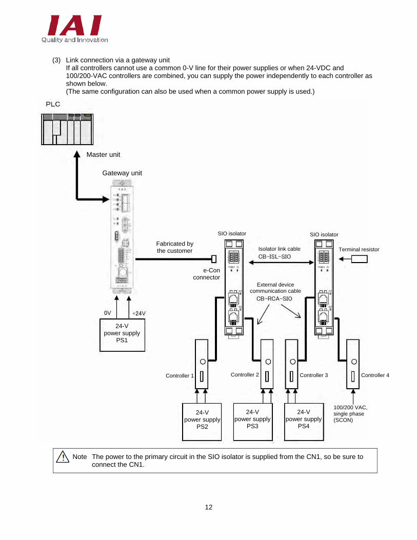
(3) Link connection via a gateway unit
If all controllers cannot use a common 0-V line for their power supplies or when 24-VDC and 100/200-VAC controllers are combined, you can supply the power independently to each controller as shown below. (The same configuration can also be used when a common power supply is used.)
Note The power to the primary circuit in the SIO isolator is supplied from the CN1, so be sure to connect the CN1.
Master unit
SIO isolator
Controller 1 Controller 2 Controller 3 Controller 4
External device communication cable
Isolator link cable
SIO isolator
Terminal resistorFabricated by the customer
24-V power supply
PS2
24-V power supply
PS3
24-V power supply
PS4
24-V power supply
PS1
100/200 VAC, single phase (SCON)
Gateway unit
e-Conconnector
13
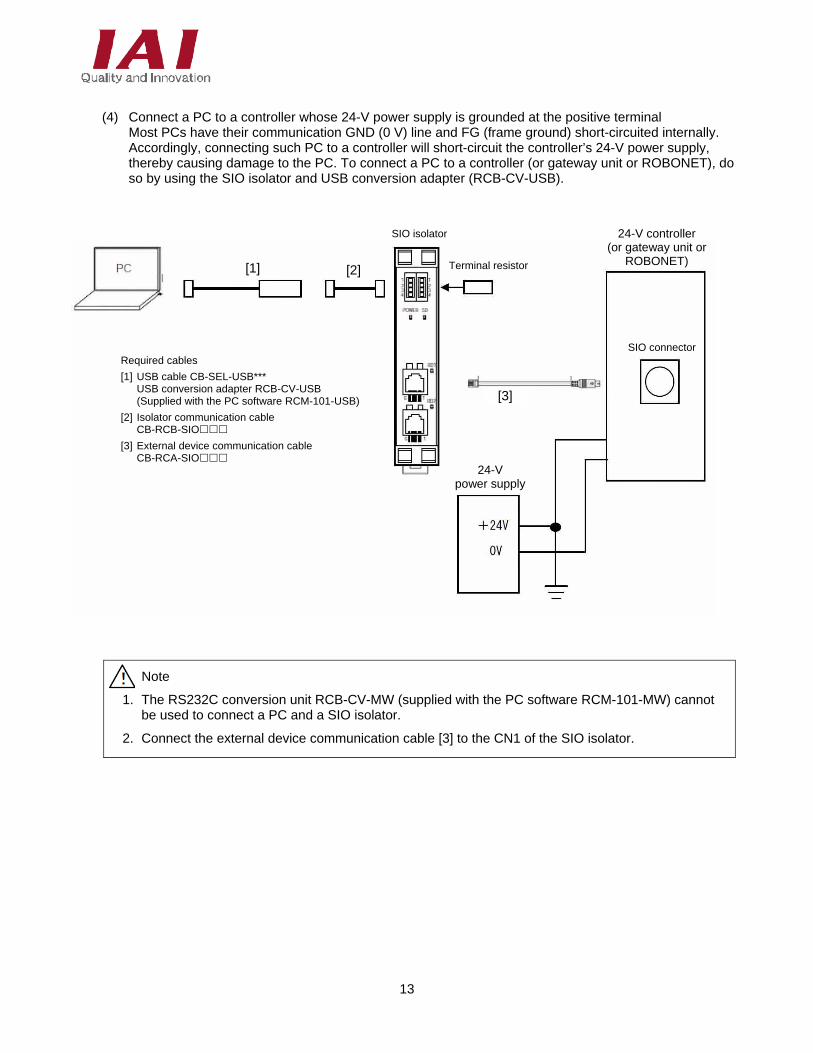
(4) Connect a PC to a controller whose 24-V power supply is grounded at the positive terminal
Most PCs have their communication GND (0 V) line and FG (frame ground) short-circuited internally. Accordingly, connecting such PC to a controller will short-circuit the controller’s 24-V power supply, thereby causing damage to the PC. To connect a PC to a controller (or gateway unit or ROBONET), do so by using the SIO isolator and USB conversion adapter (RCB-CV-USB).
Note
1. The RS232C conversion unit RCB-CV-MW (supplied with the PC software RCM-101-MW) cannot be used to connect a PC and a SIO isolator.
2. Connect the external device communication cable [3] to the CN1 of the SIO isolator.
SIO isolator
24-V power supply
24-V controller (or gateway unit or
ROBONET)
SIO connector
Terminal resistor [1] [2]
[3]
Required cables
[1] USB cable CB-SEL-USB*** USB conversion adapter RCB-CV-USB (Supplied with the PC software RCM-101-USB)
[2] Isolator communication cable CB-RCB-SIO
[3] External device communication cable CB-RCA-SIO
14
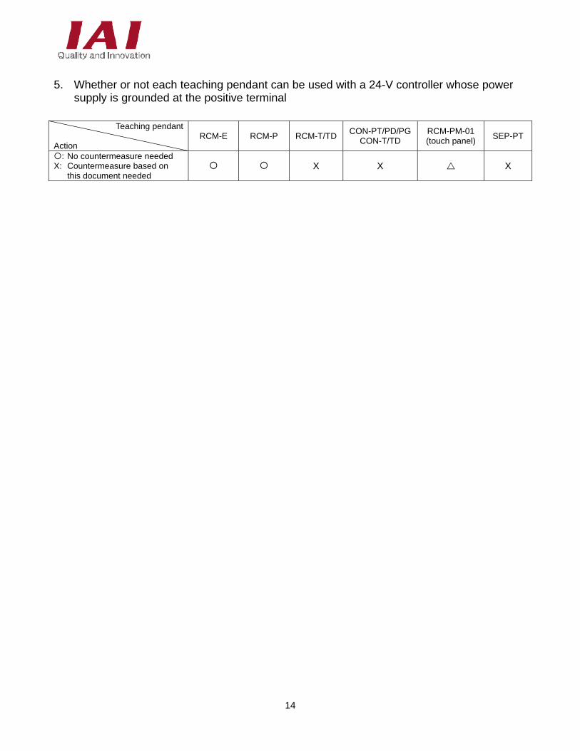
5. Whether or not each teaching pendant can be used with a 24-V controller whose power
supply is grounded at the positive terminal
Teaching pendant
Action
RCM-E RCM-P RCM-T/TDCON-PT/PD/PG
CON-T/TD RCM-PM-01 (touch panel)
SEP-PT
: No countermeasure needed X: Countermeasure based on
this document needed X X X

15
16
6. Change History
Revision Date Description of Revision
August 2010
First edition

17
Catalog No.: ME0271-1B
Head Office: 2690 W. 237th Street, Torrance, CA 90505 TEL (310) 891-6015 FAX (310) 891-0815
Chicago Office: 110 East State Parkway, Schaumburg, IL 60173TEL (847) 908-1400 FAX (847) 908-1399
Atlanta Office: 1220 Kennestone Circle, Suite 108, Marietta, GA 30066 TEL (678) 354-9470 FAX (678) 354-9471
website: www.intelligentactuator.com
Ober der Röth 4, D-65824 Schwalbach am Taunus, Germany TEL 06196-88950 FAX 06196-889524
IAI (Shanghai) Co., Ltd. SHANGHAI JIAHUA BUSINESS CENTER A8-303, 808,Hongqiao Rd. Shanghai 200030, China
TEL 021+6448-4753 FX 021-6448-3992 website: www.iai-robot.com
The information contained in this document is subject to change without notice for the purpose of product improvement. Copyright 2014. Oct. IAI Corporation. All rights reserved.