Embed Size (px)
Citation preview
Numerical Analysis of Bird StrikeDamage on Composite SandwichStructure Using Abaqus/ Explicit
A project present to The Faculty of the Department of Aerospace Engineering
San Jose State University
in partial fulfillment of the requirements for the degree Master of Science in Aerospace Engineering
By
Rahulkumar K. Mav
December 2013
approved by
Dr. Nikos Mourtos Faculty Advisor
1
Approved by
2
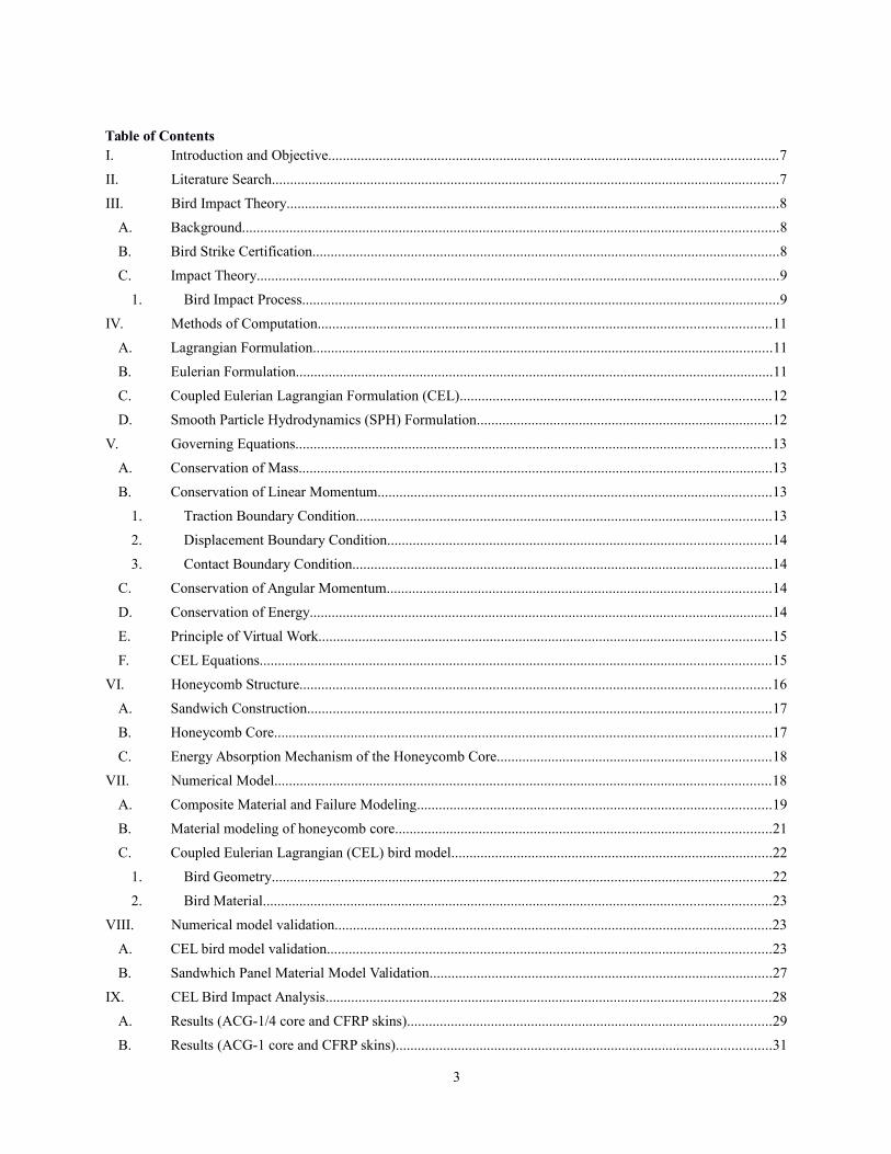
Table of ContentsI. Introduction and Objective...........................................................................................................................7
II. Literature Search...........................................................................................................................................7
III. Bird Impact Theory.......................................................................................................................................8
A. Background...................................................................................................................................................8
B. Bird Strike Certification................................................................................................................................8
C. Impact Theory...............................................................................................................................................9
1. Bird Impact Process...................................................................................................................................9
IV. Methods of Computation............................................................................................................................11
A. Lagrangian Formulation..............................................................................................................................11
B. Eulerian Formulation...................................................................................................................................11
C. Coupled Eulerian Lagrangian Formulation (CEL).....................................................................................12
D. Smooth Particle Hydrodynamics (SPH) Formulation.................................................................................12
V. Governing Equations..................................................................................................................................13
A. Conservation of Mass..................................................................................................................................13
B. Conservation of Linear Momentum............................................................................................................13
1. Traction Boundary Condition..................................................................................................................13
2. Displacement Boundary Condition.........................................................................................................14
3. Contact Boundary Condition...................................................................................................................14
C. Conservation of Angular Momentum.........................................................................................................14
D. Conservation of Energy...............................................................................................................................14
E. Principle of Virtual Work............................................................................................................................15
F. CEL Equations............................................................................................................................................15
VI. Honeycomb Structure.................................................................................................................................16
A. Sandwich Construction...............................................................................................................................17
B. Honeycomb Core........................................................................................................................................17
C. Energy Absorption Mechanism of the Honeycomb Core...........................................................................18
VII. Numerical Model........................................................................................................................................18
A. Composite Material and Failure Modeling.................................................................................................19
B. Material modeling of honeycomb core.......................................................................................................21
C. Coupled Eulerian Lagrangian (CEL) bird model........................................................................................22
1. Bird Geometry.........................................................................................................................................22
2. Bird Material...........................................................................................................................................23
VIII. Numerical model validation........................................................................................................................23
A. CEL bird model validation..........................................................................................................................23
B. Sandwhich Panel Material Model Validation..............................................................................................27
IX. CEL Bird Impact Analysis..........................................................................................................................28
A. Results (ACG-1/4 core and CFRP skins)....................................................................................................29
B. Results (ACG-1 core and CFRP skins).......................................................................................................31
3
C. Energy balance............................................................................................................................................32
D. Core comparison.........................................................................................................................................34
X. Conclusion..................................................................................................................................................36
XI. Bibliography...............................................................................................................................................37
List of Figures
Figure 1: Bird impact process [25].........................................................................................................................10
Figure 2: Lagrangian deformation for soft body impact simulation [22]...............................................................11
Figure 3: Simulation in Eulerian formulation [23].................................................................................................12
Figure 4: Soft body impact in CEL formulation [22].............................................................................................12
Figure 5: Soft body impact in SPH formulation [22]..............................................................................................13
Figure 6: Sandwich Panel [35]................................................................................................................................17
Figure 7: Honeycomb Core and its Terminology [35]............................................................................................17
Figure 8: Load-Displacement Curve of Out-of-Plane Compression of Honeycomb Core [36].............................18
Figure 9: Wing Leading Edge Finite Element Mesh...............................................................................................19
Figure 10: Equivalent Stress-Displacement Diagram [4].......................................................................................20
Figure 11: Damage Variable as a function of Equivalent Displacement [4]...........................................................21
Figure 12: Schematic Stress-Strain Curve for Honeycomb [39]............................................................................21
Figure 13: Bird geometry (All dimensions are in meters)......................................................................................23
Figure 14: Bird model setup (Lagrangian Formulation).........................................................................................24
Figure 15: Bird model setup (CEL Formulation)....................................................................................................24
Figure 16: Displacement contours of Aluminum plate (Lagrangian Method), at V = 150 m/s..............................25
Figure 17: Displacement contours of Aluminum plate (CEL Method), at V = 150 m/s.........................................25
Figure 18: Bird Impact at various time interval, at V = 150 m/s............................................................................26
Figure 19: Displacement vs. Time, CEL Bird Impactor, at V = 150 m/s................................................................27
Figure 20: Sandwich panel verification setup.........................................................................................................27
Figure 21: Residual velocity versus Impact velocity..............................................................................................28
Figure 22: CEL model of leading edge bird strike analysis....................................................................................28
Figure 23: Bird strike event at different time interval (ACG-1/4 core and CFRP skin).........................................29
Figure 24: Composite top skin failure modes (ACG-1/4 core and CFRP skins)....................................................30
Figure 25: Bird strike event at different time interval (ACG-1 core and CFRP skins)...........................................31
Figure 26: Composite top skin failure modes (ACG-1 core and CFRP skins).......................................................32
Figure 27: Energy balance chart for the wing leading edge (CFRP skins and ACG-1/4 core)...............................33
Figure 28: Energy balance chart for the wing leading edge (CFRP skins and ACG-1 core)..................................33
Figure 29: Front spar deflection due to bird impact (ACG-1/4 core and CFRP skins)...........................................34
Figure 30: Front spar deflection due to bird impact (ACG-1 core and CFRP skins)..............................................34
Figure 31: Stress vs. Strain curve for ACG-1/4 honeycomb core...........................................................................35
Figure 32: Stress vs. Strain curve for ACG-1 honeycomb core..............................................................................35
Figure 33: Kinetic energy absorbed vs. Time (ACG-1/4 core and CFRP skins)....................................................36
Figure 34: Kinetic energy absorbed vs. Time (ACG-1 core and CFRP skins).......................................................36
4
List of Tables
Table 1: Bird Strike Test Requirements [6]...............................................................................................................9
Table 2: Mechanical Properties of CFRP AS4/8552 [41].......................................................................................19
Table 3: Aluminum Commercial Grade (ACG) for 3000 Series Alloy [36]...........................................................22
Table 4: Mechanical properties of Aluminum 6061-T6 [32]..................................................................................24
5
Numerical analysis of Bird Strike Damage on Compositesandwich structure
Rahulkumar K. MavSan Jose State University, San Jose, CA 95192
The present work shows extensive use of the non-linear dynamic finite element code tosimulate a bird impact event on the composite sandwich wing leading edge rather thanexpensive full-scale gas-gun type of experimental method. Two sandwich panels used in theseanalyses consist of Aerospace Commercial Grade (ACG) – 1/4 inch cell size core & carbonfiber composite skins, and Aerospace Commercial Grade (ACG) – 1 inch cell size core &carbon fiber composite skins. Although, sandwich panel has high stiffness and strength, itsbehavior under impact loading depends on mechanical properties of its constituents and theadhesive capability between two interfaces. Hence, it is highly responsive to slight changes incore material, type, and density, as well as, composite skin material, and fiber orientation.This paper details four failure modes of unidirectional carbon fiber composite skin with[90/45]2 laminate configuration, and also comparative study of energy absorbing capabilitiesof two honeycomb cores with different strengths.
Nomenclature
T = Duration of impact (squash-up time)L = Length of the bird
ν0 = Initial impact velocity
ρ0 = Material initial density
ρ = Current density
U 0 = Velocity of the bird material
U s = Velocity of the shock in the bird material
U SP = Shock velocity of projectile
U ST = Shock velocity of target
Pc = Pressure at the center of the impact zone
c0 = Speed of sound in the material
s = Material constant
η = Nominal volumetric compressive strain (1−ρ 0/ ρ)
Γ0 = Grüneisen coefficient
Em = Internal energy per unit mass
6
J = Jacobian determinant
ti = Components of the traction vector
ni = Components of the surface normal
Di = Component of the enforced displacement vector
εij = Strain rate tensor
W ij = Vorticity or Spin tensor
δxi = Arbitrary test functions, can be interpreted as the virtual displacement field
dS = Area of a differential segment
ai = Acceleration
ε0pl
= Initial value of equivalent plastic strain
ε pl = Equivalent plastic strain rate
ε fpl
= Strain at failure
ε pl = Plastic strain increment
x i = Current position of a point
X j = Location of the point in the original or reference frame
σ ij , j = Cauchy stress
bi = Applied body force per unit mass
ν i = Velocity in the current configuration
E1 = Young modulus (Longitudinal directional)E2 = Young modulus (Transverse directional)G12 = Shear modulus
ν12 = Poisson ratio
+¿S11
¿= Longitudinal tensile failure strength
−¿S11
¿= Longitudinal compressive failure strength
+¿S22
¿= Transverse tensile failure strength
7
−¿S22
¿= Transverse compressive failure strength
S12 = Longitudinal shear failure strength
S23 = Transverse shear failure strength
+¿F f
¿= Fiber failure index in tension
−¿F f
¿= Fiber failure index in compression
+¿Fm
¿= Matrix failure index in tension
−¿Fm
¿= Matrix failure index in compressive
Cd = Elasticity matrix including damage
I. Introduction and Objective
s classic species of cellular materials, honeycombs have attracted a great deal of attention due to theiroutstanding properties, such as high relative stiffness and strength, good insulation, and lightweight.However, the sandwich structures are inherently susceptible to localized damage when subjected to
localized transverse loads. Foreign Object Debris (FOD) is one of the common types of localized loads that mayinduce impact damage and result in reduction of static and/or fatigue strength of the sandwich structures. The impactbehavior of a sandwich panel depends on many factors, such as mechanical properties of its constituents, skins, core,and adhesive capacity of the skin core interface. Regardless of extensive research on the sandwich structures, theirimpact behavior is still not fully understood [20].
A
The threat of bird strike event increases frequently due to rapidly growing air traffic and changes in the migrationroutes of the bird flocks [18]. The bird strike causes significant economic loss for all aviation, estimated at over $3billion worldwide every year [19]. Many incidences were recorded in the past with the loss of aircrafts and evenhumans. Certification standards, which include the necessary level of tolerance to the bird strikes of aircraftstructural parts, are established by U.S. Federal Aviation Administration (FAA) and European Aviation SafetyAgency [EASA]. Generally, the bird strike testing on any structure part is done using gas-gun equipment that useshelium gas to shoot a real bird on a target. These empirical verifications, which cause damage of prototypes and thebiological hazard of using real birds, can be costly and time consuming. The use of numerical methods serves as apowerful tool to support the certification process in order to minimize the cost of empirical testing.
The principle objective of the present work is to provide a numerical procedure that is capable of evaluating theresidual compressive strength and the failure mechanisms of an aluminum-cored sandwich panels after a soft bodyimpact. An accurate damage prediction of a composite honeycomb sandwich structure necessitates an appropriatemodeling of the bird material, formulation methodology, and composite and honeycomb material.
II. Literature Search
As mentioned in the introduction that the impact behavior of honeycomb sandwich structures is still underinvestigation. G. Villanueva and W. Cantwell investigated a range of novel aluminum foam sandwich structureunder high impact velocity using nitrogen gas gun equipment. They used a 10 mm diameter metallic projectile toexamine the various failure modes. Harte et al. noticed three failure modes, such as face sheet yield, core shearing,
8
and indentation, of the sandwich composite structure under roller loading [14]. Similarly, McCormack et al.observed similar failure modes in addition to the face wrinkling in sandwich beams tested under three-point bendingloading conditions [15]. The characteristics of the energy absorption capacity of a bare honeycomb cored underlateral crushing loads have been studied, both theoretically and experimentally, by Kunimoto et al. [16]. Highvelocity impact tests on the sandwich structures resulted in a number of different failure modes.
The earliest investigators, Wilbeck and Welsh, conducted a very comprehensive testing program to develop asubstitute, synthetic bird model [1] [2]. In the past, for making a bird-proof design of aircraft components, it was acommon practice to make and test the parts, then redesign and test them again. One example of this procedure isdocumented for the development of the bird-proof Dash 8 wing leading edge [8]. Without any doubts, this iscertainly a time consuming and expensive method. Therefore, numerical methods are now adopted by aviationindustries for the purpose of rapid and improved design optimization, ensuring that the very first full-scale birdstrike certification test is successful. Outstanding work was done on bird strike impact numerical analysis bySmojver et al. [3] [4] [5]. McCarthy et al. carried out the analysis on Fiber Metal Laminates (FML), a family ofmaterial consisting of alternative plies of thin aluminum and fiber/epoxy with high specific strength, using SmoothParticle Hydrodynamics (SPH) method in PAM crash software [10]. Few works involve aerospace structures madeof carbon-fiber reinforced polymer (CFRP) and Aramid fibers [11].
Earlier investigations in bird strike involved metallic projectiles-honeycomb structure targets, soft bodyprojectiles-metallic/composite structures targets, and development of methodologies. The results from the metallicprojectile-honeycomb structure target are not identical with the soft body projectile-honeycomb structure target.Hence, the detailed examination of the behavior of the composite sandwich structure is necessary to study itsvulnerability under the soft body impact loading.
III. Bird Impact Theory
A BackgroundMany aircrafts’ exteriors are susceptible to collision with the birds, particularly during takeoff and landing
phases. However, the high altitude impact cases had also been noted in the past. In order to assure the minimumsafety standards in cases of the bird impacts, the international airworthiness standards require that the airplane testsmust be conducted to demonstrate certain levels of capabilities, specified in terms of structural resistance andallowable degradation in flying qualities.
Various certification requirements are set by the certification authorities depending on the parts. Different weightbirds are specified for the windshields, the wings, the empennage, and the engines. The final designs and acceptanceof the bird resistant components are typically dependent on the testing. The typical method of the bird proofing anairplane is to build and test, then redesign and test again.
A.Bird Strike Certification The bird strike tests are carried out in accordance with Federal Aviation Regulation (FAR) Parts 23, 25 and 33, as
shown in Table 1. Earlier the tests used to involve a live chicken of an appropriate weight shooting against astructure that needs to be certified. However, for the simplicity, the sanitary, and the repeatability reasons, thesynthetic bird of an appropriate size and weight is now used. The gas-gun type shooting cannon is used for thecertification testing having 5-10 inches of diameter.
A typical windshield test program involves several birdshots at various locations of the windshield and the frame.In order to get the bird strike certification for the windshield and the frame, they have to show that the pilots shouldnot be injured by the bird, the windshield fragments, the broken airframe, or the interior parts; and that the damagedstructure and windshield should still hold the cabin pressure following the bird strike event. High-speed cameras,usually 10,000-20,000 frames per second, are placed inside and outside the cockpit to capture the details of anyfailure.
For the aircraft wing, the birdshots are done at the inboard and the outboard leading edges. The goal here is toshow that the bird does not penetrate the wing leading edge, or even in case of penetration, it does not create anycritical damage to the wing front spar. The splitter plates, in the forms of triangular boxes, are often placed inside theleading edge skins to deflect the bird, and reinforce the leading edge structure.
9
The empennage is targeted at several spots along the leading edges of the vertical fin and the stabilizer, wherevulnerabilities due to impacts are expected to be the highest. Like the wing, the typical goal is to prevent the frontspar from critical damage to occur due to the bird strike. Here also, the splitter plates inside the skins are used toreinforce the leading edge structure.
For the engine, bird strike tests include the investigations of the impact effects on the engine operation as well ason the fan disk integrity. The engine operation test requires that the engine must continue to produce 75% of thethrust for 5 minutes after ingesting a small or medium size flock, as shown in Table 1. In Fan integrity test, theengine must not catch fire or disintegrate after being struck by a single 4 lb bird.
Table 1: Bird Strike Test Requirements [6]
FAR SectionAircraft
ComponentsBird Strike Parameters Performance
RequirementBird Mass Aircraft Speed
25.571 (e) (1) General Structure 4 lb.VC @ sea level/
0.85 VC @ 8000 ftSuccessful completion
of flight
25.631 Empennage 8 lb. VC @ sea levelContinued safe flight
and landing
25.775 (b) Windshield 4 lb. VC @ sea levelBird does not penetrate
windshield
33.77,25.571(e)(1)
Engine - ContinuedOperation
Up to 16 of 3 ozbirds
Not Specified
Engine must produce75% of thrust for 5
minutesUp to 8 of 1.5 lb
birds
B.Impact TheoryThere are three major categories of the impact event: Elastic impact, Plastic impact, and Hydrodynamic impact.
These impacts are categorized based on the impact velocity, and the level of the stresses generated in a projectile dueto the impact.
The elastic impact is typically a low speed event, and the stresses generated due to collision are lower than thematerial yield stress. Therefore, the nature and duration of the impact depend on the elastic modulus and the elasticwave velocities of the materials. In case of a high impact speed, the produced stresses cause plastic deformation ofthe targeted material. For this event, the material strength is still a dominating factor, and hence such impact fallsunder the plastic impact category. Finally, for a very high impact velocity, the stresses generated by the decelerationof the projectile greatly excel the yield stress of the projectile material. This is the hydrodynamic regime, for whichthe projectile can be treated as a fluid.
1. Bird Impact ProcessThe bird impact process can be considered as the hydrodynamic impact. Peterson and Barber [24] summarized
that the birds essentially behave like fluids during impacts; they do not bounce; and the impact duration isapproximated from the bird squash-up time [24]. The squash-up time is given by
T=Lν0
(1)
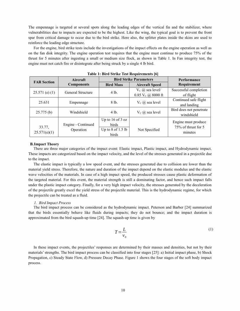
In these impact events, the projectiles’ responses are determined by their masses and densities, but not by theirmaterials’ strengths. The bird impact process can be classified into four stages [25]: a) Initial impact phase, b) ShockPropagation, c) Steady State Flow, d) Pressure Decay Phase. Figure 1 shows the four stages of the soft body impactprocess.
10
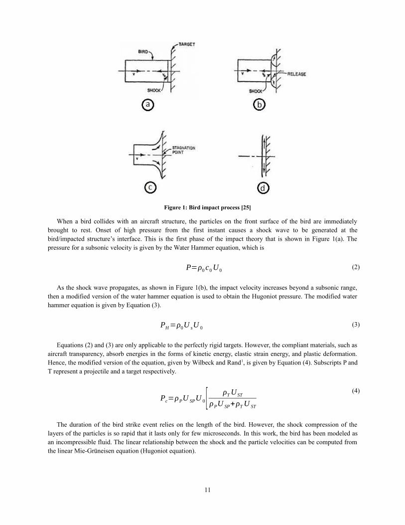
Figure 1: Bird impact process [25]
When a bird collides with an aircraft structure, the particles on the front surface of the bird are immediatelybrought to rest. Onset of high pressure from the first instant causes a shock wave to be generated at thebird/impacted structure’s interface. This is the first phase of the impact theory that is shown in Figure 1(a). Thepressure for a subsonic velocity is given by the Water Hammer equation, which is
P=ρ0 c0U0(2)
As the shock wave propagates, as shown in Figure 1(b), the impact velocity increases beyond a subsonic range,then a modified version of the water hammer equation is used to obtain the Hugoniot pressure. The modified waterhammer equation is given by Equation (3).
PH=ρ0U sU 0(3)
Equations (2) and (3) are only applicable to the perfectly rigid targets. However, the compliant materials, such asaircraft transparency, absorb energies in the forms of kinetic energy, elastic strain energy, and plastic deformation.Hence, the modified version of the equation, given by Wilbeck and Rand1, is given by Equation (4). Subscripts P andT represent a projectile and a target respectively.
Pc=ρPU SPU 0[ ρTU ST
ρPU SP+ρTU ST]
(4)
The duration of the bird strike event relies on the length of the bird. However, the shock compression of thelayers of the particles is so rapid that it lasts only for few microseconds. In this work, the bird has been modeled asan incompressible fluid. The linear relationship between the shock and the particle velocities can be computed fromthe linear Mie-Grüneisen equation (Hugoniot equation).
11
U s=sU 0+c0(5)
The final form of the pressure is given by following equation.
P=ρ0 c0
2η
(1−sη )2 (1−Γ 0η
2 )+Γ0 ρ0 Em
(6)
Because of the very high-pressure gradient, the bird particles accelerate radially outward, and a release wave isformed. The function of the release wave is to relieve the radial pressures in the projectile. After several reflectionsof the release waves, the steady state condition is established as shown in Figure 1(c). The stagnation pressure on theimpacted surface during this steady state is given by
Ps=k ρ0U 02 (7)
This stagnation pressure is independent of the bird shape. The steady state pressure is usually taken as 10-30% ofthe peak Hugoniot shock pressure at the center of the impacted region, based on experimental studies [26]. For anincompressible fluid, k = 0.5; but for most materials, the density increases with the pressure, and as a result, k mayapproach a value of 1.
IV. Methods of Computation
Despite the extensive researches on a soft body impact, there is not any standardized method available to analyzethe fluid-structure interaction impact problems. There are many methodologies present in different finite elementcodes. The selection of an appropriate method would often lead the solution closer to the experimental solution. Itcould be beneficial to couple different numerical solvers in order to leverage the advantages of each method.
There are currently four modeling methods available, such as Lagrangian, Eulerian, Coupled LagrangianEulerian (CEL), and Smooth Particle Hydrodynamics, which are being used for the impact damage analyses. Eachmethodology has its own strengths and weaknesses.
A Lagrangian FormulationIn the Lagrangian formulation, the volume is divided into a large number of small geometries called elements.
Mesh nodes are connected to a material by certain imaginary points called Integration points. The mesh follows thematerial, i.e. one material per element, during entire simulation. This formulation is generally used for solidmaterials. In the Lagrangian approach, the history dependent variables can easily be tracked. However, the majordrawback of the Lagrangian formulation is that the large distortion of a part leads to hopeless mesh and elementdistortions causing inaccurate results and error termination of an analysis. The deformation of Lagrangian mesh [22]is shown in Figure 2 at different instants of time.
Figure 2: Lagrangian deformation for soft body impact simulation [22]
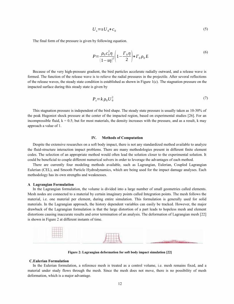
C.Eulerian FormulationIn the Eulerian formulation, a reference mesh is treated as a control volume, i.e. mesh remains fixed, and a
material under study flows through the mesh. Since the mesh does not move, there is no possibility of meshdeformation, which is a major advantage.
12
This formulation is mostly applied to fluid applications. However, the Eulerian formulation requires morecomputations than the Lagrangian, which results in longer simulation time. In addition, it is very difficult to trackthe material interfaces, and the history of material variables. In Figure 3, the soft body impact simulation using theEulerian formulation is shown at different instants of time.
Figure 3: Simulation in Eulerian formulation [23]
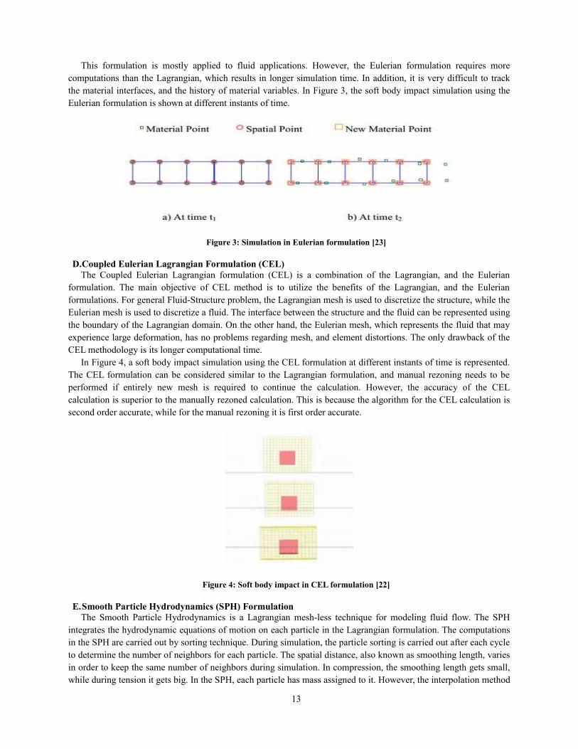
D.Coupled Eulerian Lagrangian Formulation (CEL)The Coupled Eulerian Lagrangian formulation (CEL) is a combination of the Lagrangian, and the Eulerian
formulation. The main objective of CEL method is to utilize the benefits of the Lagrangian, and the Eulerianformulations. For general Fluid-Structure problem, the Lagrangian mesh is used to discretize the structure, while theEulerian mesh is used to discretize a fluid. The interface between the structure and the fluid can be represented usingthe boundary of the Lagrangian domain. On the other hand, the Eulerian mesh, which represents the fluid that mayexperience large deformation, has no problems regarding mesh, and element distortions. The only drawback of theCEL methodology is its longer computational time.
In Figure 4, a soft body impact simulation using the CEL formulation at different instants of time is represented.The CEL formulation can be considered similar to the Lagrangian formulation, and manual rezoning needs to beperformed if entirely new mesh is required to continue the calculation. However, the accuracy of the CELcalculation is superior to the manually rezoned calculation. This is because the algorithm for the CEL calculation issecond order accurate, while for the manual rezoning it is first order accurate.
Figure 4: Soft body impact in CEL formulation [22]
E.Smooth Particle Hydrodynamics (SPH) FormulationThe Smooth Particle Hydrodynamics is a Lagrangian mesh-less technique for modeling fluid flow. The SPH
integrates the hydrodynamic equations of motion on each particle in the Lagrangian formulation. The computationsin the SPH are carried out by sorting technique. During simulation, the particle sorting is carried out after each cycleto determine the number of neighbors for each particle. The spatial distance, also known as smoothing length, variesin order to keep the same number of neighbors during simulation. In compression, the smoothing length gets small,while during tension it gets big. In the SPH, each particle has mass assigned to it. However, the interpolation method
13
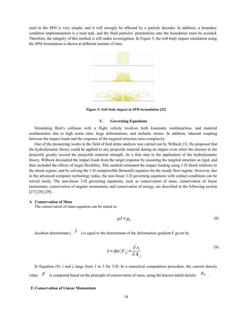
used in the SPH is very simple, and it will strongly be affected by a particle disorder. In addition, a boundarycondition implementation is a hard task, and the fluid particles’ penetrations into the boundaries must be avoided.Therefore, the integrity of this method is still under investigation. In Figure 5, the soft body impact simulation usingthe SPH formulation is shown at different instants of time.
Figure 5: Soft body impact in SPH formulation [22]
V. Governing Equations
Simulating Bird’s collision with a flight vehicle involves both kinematic nonlinearities, and materialnonlinearities due to high strain rates, large deformations, and inelastic strains. In addition, inherent couplingbetween the impact loads and the response of the targeted structure raise complexity.
One of the pioneering works in the field of bird strike analysis was carried out by Wilbeck [1]. He proposed thatthe hydrodynamic theory could be applied to any projectile material during an impact even when the stresses in theprojectile greatly exceed the projectile material strength. As a first step in the application of the hydrodynamictheory, Wilbeck decoupled the impact loads from the target response by assuming the targeted structure as rigid, andthen included the effects of target flexibility. This method estimated the impact loading using 1-D shock relations inthe shock regime, and by solving the 1-D compressible Bernoulli equation for the steady flow regime. However, dueto the advanced computer technology today, the non-linear 3-D governing equations with contact conditions can besolved easily. The non-linear 3-D governing equations, such as conservation of mass, conservation of linearmomentum, conservation of angular momentum, and conservation of energy, are described in the following section[27] [28] [29].
A Conservation of MassThe conservation of mass equation can be stated as
ρJ=ρ0(8)
Jacobian determinant ( J ) is equal to the determinant of the deformation gradient F given by
J=det (F ij)=∂ x i∂ X j
(9)
In Equation (9), i and j range from 1 to 3 for 3-D. In a numerical computation procedure, the current density
value ρ is computed based on the principle of conservation of mass, using the known initial density ρ0 .
F. Conservation of Linear Momentum
14
The conservation of linear momentum can be stated as Equation (10) under the appropriate boundary conditions.
The dot above ν i represents the material time derivative.
σ ij , j+ ρbi=ρ νi (10)
The application boundary conditions can take the following three forms:
1 Traction Boundary ConditionThe traction boundary condition can be written as
σ ij ni=t i (11)
2. Displacement Boundary ConditionThe displacement boundary is formulated as follow:
x i (X i , t )=Di (t ) (12)
3. Contact Boundary ConditionAt the contact surface, the displacement components of the two contacting surfaces must satisfy the constraint
given Equation (13). Superscripts α and β refer to the two contacting surfaces.
(x iα−x i
β )niα ≤0 (13)
In Equation (13), when the constraint is equality, the normal component of the tractions on the contactingsurfaces must be equal and opposite. This condition can be written as
σ ijα ni
α n jα−σ ij
βniβn j
β=0 (14)
G. Conservation of Angular MomentumIn the absence of body couples, conservation of angular momentum simply states that the Cauchy stress tensor is
symmetric, that is,
σ ij=σ ji(15)
H. Conservation of EnergyThe conservation of energy equation is used to compute the internal energy (e), which is used in the equation of
state to obtain the pressure-density relationship of a given material. The conservation of energy can be written as
ρ e=σ ij εij+ ρbi ν i (16)
15
The strain rate is the same as the deformation rateDij . The deformation rate
Dij is obtained from the
velocity gradientLij . The velocity gradient
Lij is defined as
Lij=∂ ν i∂x j
(17)
The velocity gradient Lij can be split into a symmetric component
Dij and a skew-symmetric component
W ij as follows:
Dij=12
(Lij+L ji)(18)
W ij=12
(Lij−L ji )(19)
I. Principle of Virtual WorkThe finite element method uses the weak form of the momentum equation. In mechanics, the weak form is often
referred to as the “principle of virtual work”. The principle of virtual work is the weak form of the equation ofconservation of linear momentum along with the traction, displacement, and contact discontinuity boundaryconditions. The linear momentum equation along with the prescribed boundary conditions is called the generalizedmomentum balance. The weak form of the generalized momentum balance can be written as follows:
∫V
(σ ij, j+ρ bi−ρ v i )δxidV +∫Γ t
(t i−σ ij n j )δx idS−∫Γα
(σ ijα ni
α n jα−σ ij
βniβn j
β )δx kαnk
α dS=0(20)
δxi must vanish everywhere except where the enforced displacement conditions exist. Using integration by
parts, the first term in the above equation ∫V
σ ij , j δxi dV can be written as
∫V
σ ij, j δxidV=∫V
[ (σ ij , j δxi ) , j−σ ijδxi , j ]dV(21)
By applying the Gauss’s divergence theorem, the first term on the right hand side of Equation (21) can be writtenas,
16
(σ ij , j δxi ) , j dV=¿∫Γ t
σ ijn j δxi dS+∫Γα
(σ ijα ni
αn jα−σ ij
βniβn j
β )δx kα nk
α dS
∫V
¿
(22)
Using Equation (22), the principle of virtual work now becomes
δπ=∫V
σ ijδxi , j dV +∫V
ρai δxidV−∫V
ρbi δxidV−∫Γ t
t i δxidS=0(23)
J. CEL EquationsThe Coupled Eulerian Lagrangian (CEL) formulation contains both, the Lagrangian and Eulerian, equations as
subsets. The velocity of the material is u, the velocity of the reference coordinates is v, and their difference, u-v, isdenoted as w. The Jacobian, J’, is the relative differential volume between the reference and spatial coordinates.
∂J '
∂t=J '
∂ v i∂ x i
(24)
The material time derivative can be expressed in terms of both the spatial and reference coordinates, where
f r means that f is expressed as a function of the reference coordinates.
f=∂ f∂t
+ui∂ f∂ x i
(25a)
f=∂ f r
∂ t+(ui−v i )
∂ f∂x i
(25b)
The CEL equations are derived by substituting Equation (25) into the equations of conservation of mass,momentum, and energy, however they are not in conservation form.
∂ρ r
∂t=−ρ
∂ui∂ x i
−wi∂ρ∂ x i
(26a)
ρ∂ui
r
∂ t=(σ ij , j+ ρ bi )−ρwi
∂ui∂ x i
(26b)
ρ∂er
∂t=(σ ijui , j+ρbiui )−ρwi
∂e∂ x j
(26c)
17
To put them into conservation form, an additional identity is derived by multiplying Equation (26a) by J ' ,
multiplying Equation (24) by ρ , and adding them.
∂J ' ρ∂ t
=−J '∂ ρwi
∂ x i
(27)
After multiplying Equation (26) by f , Equation (25b) by ρ J ' , and arranging terms, the CEL equation
for f is written in its general form. The first term on the right hand side of Equation (28) is the source term for
f , and the second term, the transport of f .
∂ (J ' ρf )∂t
=J ' ρ f−J '∂ ρfw i
∂ x i
(28)
The conservation form of the CEL equations is obtained by substituting the Lagrangian equations into Equation(28).
∂ρJ '
∂ t=−J '
∂ ρwi
∂ xi
(29a)
∂ρJ 'ui∂ t
=J ' (σ ij , j+ ρb i )−J '∂ ρuiw j
∂x j
(29b)
∂ρJ 'e∂t
=J ' (σ ijui , j+ρbiui )−J '∂ρe w j
∂ x j
(29c)
When w is zero, J ' is one, and the Lagrangian equations are recovered from Equation (29). If the
reference coordinates are the current spatial coordinates, w is v , J ' is again one, and the Eulerian
equations are recovered.
VI. Honeycomb Structure
Honeycomb structures are finding increasing use in aerospace, automotive, and marine industries because oftheir relative advantages over other structural materials in terms of improved stability, high stiffness to weight andstrength to weight ratios. They provide an efficient solution to increase bending stiffness without significant increasein the structural weight. The honeycomb structure can carry both in-plane and out-of-plane loads and remains stableunder compression without a significant weight penalty.
While the preliminary design of aircraft sandwich structures have been investigated extensively in the past years,there is a lack of understanding of a soft body impact-damage mechanism, and the effect of such damage on
18
structural performance. The presence of highly complex and transient dynamic failure modes in such materials andthe inaccessibility of internal damage to real-time monitoring have limited experimental studies to the final impactdamage characteristics of the failure and residual strengths.
Sandwich constructions are being considered for applications to aircraft primary structures, where durability anddamage tolerance are the primary considerations. Therefore, understanding the adverse effects of in-service impactevents has become vital. Certification authorities, such as Federal Aviation Administration (FAA), and EuropeanAviation Safety Agency (EASA), require that exposed aircraft components must be tested to prove their capability towithstand such impact without suffering any critical damage.
The impact may induce overall or localized damage in sandwich structures. The failure characteristics ofsandwich structures are significantly different from conventional laminated structures, and are strongly dependenton the core and skin materials, and their thicknesses. The localized damage is usually confined to the top facing, thecore-top facing interface, and the core material. The bottom skin is generally left undamaged. In particular,permanent indentation in the impacted face-sheet accompanies with localized core crushing beneath and around theimpact site. The facing skin will typically rebound to some degree after the impact event; therefore, the profile of theresidual face-sheet indentation does not necessarily correspond to that of the underlying crushed core. Depending onthe size and mass of the impactor and impact energy, various damage modes that may develop failure are: (a)delamination in the impacted face-sheet, (b) skin-core debonding, (c) core crushing and shear, (d) matrix cracking,(e) fiber breakage in the facings, and (f) core buckling [34].
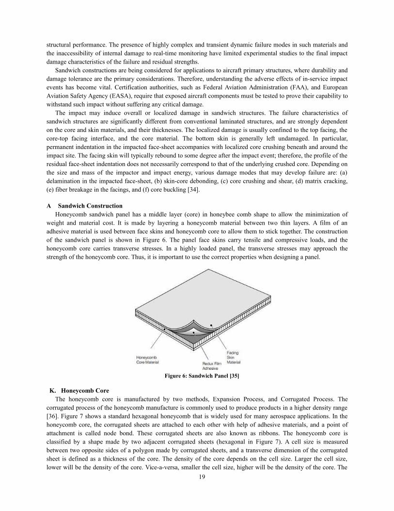
A Sandwich ConstructionHoneycomb sandwich panel has a middle layer (core) in honeybee comb shape to allow the minimization of
weight and material cost. It is made by layering a honeycomb material between two thin layers. A film of anadhesive material is used between face skins and honeycomb core to allow them to stick together. The constructionof the sandwich panel is shown in Figure 6. The panel face skins carry tensile and compressive loads, and thehoneycomb core carries transverse stresses. In a highly loaded panel, the transverse stresses may approach thestrength of the honeycomb core. Thus, it is important to use the correct properties when designing a panel.
Figure 6: Sandwich Panel [35]
K. Honeycomb CoreThe honeycomb core is manufactured by two methods, Expansion Process, and Corrugated Process. The
corrugated process of the honeycomb manufacture is commonly used to produce products in a higher density range[36]. Figure 7 shows a standard hexagonal honeycomb that is widely used for many aerospace applications. In thehoneycomb core, the corrugated sheets are attached to each other with help of adhesive materials, and a point ofattachment is called node bond. These corrugated sheets are also known as ribbons. The honeycomb core isclassified by a shape made by two adjacent corrugated sheets (hexagonal in Figure 7). A cell size is measuredbetween two opposite sides of a polygon made by corrugated sheets, and a transverse dimension of the corrugatedsheet is defined as a thickness of the core. The density of the core depends on the cell size. Larger the cell size,lower will be the density of the core. Vice-a-versa, smaller the cell size, higher will be the density of the core. The
19
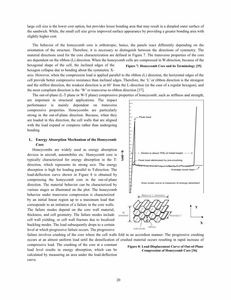
large cell size is the lower cost option, but provides lesser bonding area that may result in a dimpled outer surface ofthe sandwich. While, the small cell size gives improved surface appearance by providing a greater bonding area withslightly higher cost.
The behavior of the honeycomb core is orthotropic; hence, the panels react differently depending on theorientation of the structure. Therefore, it is necessary to distinguish between the directions of symmetry. Thematerial directions used for the core characterization are defined in Figure 7. The transverse properties of the coreare dependent on the ribbon (L) direction. When the honeycomb cells are compressed in W-direction, because of thehexagonal shape of the cell, the inclined edges of thehexagon collapse due to bending about the symmetric X-axis. However, when the compression load is applied parallel to the ribbon (L) direction, the horizontal edges of thecell provide better compressive resistance than inclined edges. Therefore, the ‘L’ or ribbon direction is the strongestand the stiffest direction, the weakest direction is at 60˚ from the L-direction (in the case of a regular hexagon), andthe most compliant direction is the ‘W’ or transverse-to-ribbon direction [37].
The out-of-plane (L-T plane or W-T plane) compressive properties of honeycomb, such as stiffness and strength,are important in structural applications. The impactperformance is mainly dependent on transversecompressive properties. Honeycombs are particularlystrong in the out-of-plane direction. Because, when theyare loaded in this direction, the cell walls that are alignedwith the load expand or compress rather than undergoingbending.
L. Energy Absorption Mechanism of the HoneycombCore
Honeycombs are widely used as energy absorptiondevices in aircraft, automobiles etc. Honeycomb core istypically characterized for energy absorption in the T-direction, which represents its strong axis. The energyabsorption is high for loading parallel to T-direction. Theload-deflection curve shown in Figure 8 is obtained bycompressing the honeycomb core in the out-of-planedirection. The material behavior can be characterized byvarious stages as illustrated on the plot. The honeycombbehavior under transverse compression is characterizedby an initial linear region up to a maximum load thatcorresponds to an initiation of a failure in the core walls.The failure modes depend on the core wall material,thickness, and cell geometry. The failure modes includecell wall yielding, or cell wall fracture due to localizedbuckling modes. The load subsequently drops to a certainlevel at which progressive failure occurs. The progressivefailure involves crushing of the core where the cell walls fold in an accordion manner. The progressive crushingoccurs at an almost uniform load until the densification of crushed material occurs resulting in rapid increase ofcompressive load. The crushing of the core at a constantload level results in energy absorption, which can becalculated by measuring an area under the load-deflectioncurve.
20
Figure 7: Honeycomb Core and its Terminology [35]
Figure 8: Load-Displacement Curve of Out-of-PlaneCompression of Honeycomb Core [36]
VII. Numerical Model
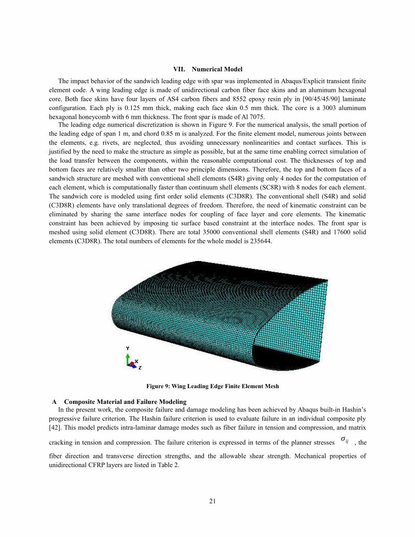
The impact behavior of the sandwich leading edge with spar was implemented in Abaqus/Explicit transient finiteelement code. A wing leading edge is made of unidirectional carbon fiber face skins and an aluminum hexagonalcore. Both face skins have four layers of AS4 carbon fibers and 8552 epoxy resin ply in [90/45/45/90] laminateconfiguration. Each ply is 0.125 mm thick, making each face skin 0.5 mm thick. The core is a 3003 aluminumhexagonal honeycomb with 6 mm thickness. The front spar is made of Al 7075.
The leading edge numerical discretization is shown in Figure 9. For the numerical analysis, the small portion ofthe leading edge of span 1 m, and chord 0.85 m is analyzed. For the finite element model, numerous joints betweenthe elements, e.g. rivets, are neglected, thus avoiding unnecessary nonlinearities and contact surfaces. This isjustified by the need to make the structure as simple as possible, but at the same time enabling correct simulation ofthe load transfer between the components, within the reasonable computational cost. The thicknesses of top andbottom faces are relatively smaller than other two principle dimensions. Therefore, the top and bottom faces of asandwich structure are meshed with conventional shell elements (S4R) giving only 4 nodes for the computation ofeach element, which is computationally faster than continuum shell elements (SC8R) with 8 nodes for each element.The sandwich core is modeled using first order solid elements (C3D8R). The conventional shell (S4R) and solid(C3D8R) elements have only translational degrees of freedom. Therefore, the need of kinematic constraint can beeliminated by sharing the same interface nodes for coupling of face layer and core elements. The kinematicconstraint has been achieved by imposing tie surface based constraint at the interface nodes. The front spar ismeshed using solid element (C3D8R). There are total 35000 conventional shell elements (S4R) and 17600 solidelements (C3D8R). The total numbers of elements for the whole model is 235644.
Figure 9: Wing Leading Edge Finite Element Mesh
A Composite Material and Failure ModelingIn the present work, the composite failure and damage modeling has been achieved by Abaqus built-in Hashin’s
progressive failure criterion. The Hashin failure criterion is used to evaluate failure in an individual composite ply[42]. This model predicts intra-laminar damage modes such as fiber failure in tension and compression, and matrix
cracking in tension and compression. The failure criterion is expressed in terms of the planner stressesσ ij , the
fiber direction and transverse direction strengths, and the allowable shear strength. Mechanical properties ofunidirectional CFRP layers are listed in Table 2.
21
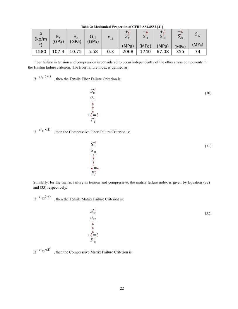
Table 2: Mechanical Properties of CFRP AS4/8552 [41]
ρ(kg/m
3)
E1
(GPa)E2
(GPa)G12
(GPa)ν12
+¿S11
¿
(MPa)
−¿S11
¿
(MPa)
+¿S22
¿
(MPa)
−¿S22
¿
(MPa)
S12
(MPa)
1580 107.3 10.75 5.58 0.3 2068 1740 67.08 355 74
Fiber failure in tension and compression is considered to occur independently of the other stress components in the Hashin failure criterion. The fiber failure index is defined as,
Ifσ11≥0
, then the Tensile Fiber Failure Criterion is:
S11+¿
σ11
¿¿¿
+¿=¿F f
¿
(30)
Ifσ11<0
, then the Compressive Fiber Failure Criterion is:
S11−¿
σ 11
¿¿¿
−¿=¿F f
¿
(31)
Similarly, for the matrix failure in tension and compressive, the matrix failure index is given by Equation (32)and (33) respectively.
Ifσ22≥0
, then the Tensile Matrix Failure Criterion is:
S22+¿
σ22
¿¿¿
+¿=¿Fm
¿
(32)
Ifσ22<0
, then the Compressive Matrix Failure Criterion is:
22
S22−¿
2S23
¿
S22−¿
+( σ12
S12)2
≥1.0
(¿¿2−1 ]
σ22
¿¿
−¿=( σ22
2 S23)2
+¿
Fm¿
(33)
The user-defined parameter ( α ) in Hashin failure criteria determines the contribution of the longitudinal
shear stress to fiber tensile failure. The allowable range is between 0 to 1. When there is no test data available tocorrelate the failure envelop, it is recommended to set the parameter to 0. The material properties are degraded based
upon the damage mode in which damage parameters modify the initial undamaged elasticity matrix. Fiber (d f ),
matrix (dm ), and shear (
ds ) damage parameters reflect the current state of damage, having values ranging 0
to 1 for undamaged and completely degraded material, respectively. The damaged elasticity matrix has the form asbelow:
Cd=1D [
(1−d f ) E1 (1−d f ) (1−dm )ν21E1 0
(1−d f ) (1−dm ) ν12 E2 (1−dm ) E2 0
0 0 (1−ds )G12 D]
(34)
Where D =1−(1−d f ) (1−dm )ν12 ν21 .
E1 , E2 ,
G12 , ν12 , and
ν21 are
unidirectional ply material properties.
23
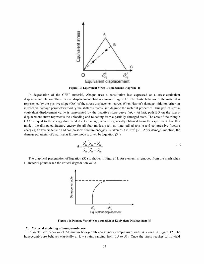
Figure 10: Equivalent Stress-Displacement Diagram [4]
In degradation of the CFRP material, Abaqus uses a constitutive law expressed as a stress-equivalentdisplacement relation. The stress vs. displacement chart is shown in Figure 10. The elastic behavior of the material isrepresented by the positive slope (OA) of the stress-displacement curve. When Hashin’s damage initiation criterionis reached, damage parameters modify the stiffness matrix and degrade the material properties. This part of stress-equivalent displacement curve is represented by the negative slope curve (AC). At last, path BO on the stress-displacement curve represents the unloading and reloading from a partially damaged state. The area of the triangleOAC is equal to the energy dissipated due to damage, which is generally obtained from the experiment. For thismodel, the dissipated fracture energy for all four modes, such as, longitudinal tensile and compressive fractureenergies, transverse tensile and compressive fracture energies, is taken as 738 J/m2 [38]. After damage initiation, thedamage parameter of a particular failure mode is given by Equation (34).
d=δ eqf (δ eq−δ eq
0 )δ eq (δ eq
f−δ eq
0 )(35)
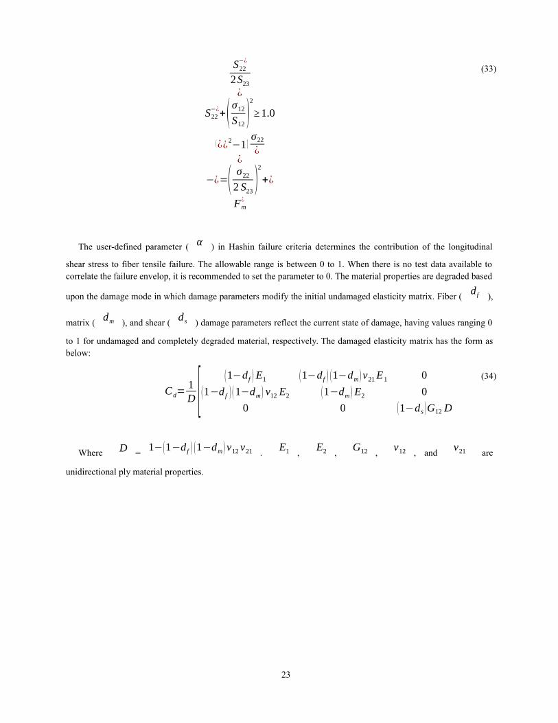
The graphical presentation of Equation (35) is shown in Figure 11. An element is removed from the mesh whenall material points reach the critical degradation value.
Figure 11: Damage Variable as a function of Equivalent Displacement [4]
M. Material modeling of honeycomb coreCharacteristic behavior of Aluminum honeycomb cores under compressive loads is shown in Figure 12. The
honeycomb core behaves elastically at low strains ranging from 0.5 to 5%. Once the stress reaches to its yield
24
strength, the progressive core crushing starts at nearly constant stress level called the plateau stress (σ pl ). At a
strain value of about 85%, the stress increases drastically due to mutual pressing of the cell walls.
Figure 12: Schematic Stress-Strain Curve for Honeycomb [39]
In Abaqus, the crushable foam material model is used to model the aluminum foam. This is a very simplematerial model, which allows for a description of the foam behavior through the input of a stress versus volumetricstrain curve. The stress versus strain behavior is depicted in Figure 12. In this model, the foam is assumed isotropicand crushed one-dimensionally with a Poisson’s ratio that is essentially zero. The model transforms the stressed intothe principal stress space where the yielding function is defined, and yielding is governed by the largest principalstress. The principal stresses are compared with the yielding stress in compression and tension. If the actual stresscomponent is compressive, then the stress has to be compared with a yield stress from a given volumetric strain-
hardening function specified by the user Y c=Y c0+H (ev ) . On the contrary, when the considered principal
stress component is tensile, the comparison with the yield surface is made with regard to a constant tensile cutoffstress, also known as crush strength. Hence, the hardening function in tension is similar to that of an elastic,perfectly plastic material. The shear failure criterion is used to remove core elements from the mesh when anequivalent plastic strain of 5% is reached. The shear failure criterion, which is highly recommended for dynamicproblems, is defined to model the failure of metallic structures. The shear failure criterion is given by Equation (34),which is based on the accumulated equivalent plastic strain [33].
ε pl= ε0pl+∫
0
t
√ 23ε pl : ε pl dt (36)
Approximately, an element fails when the damage parameter (⍵) exceeds the value of 1. The damage parameteris calculated as
ω=ε0pl+∑ ∆ ε pl
ε fpl
(37)
Mechanical properties of the honeycomb core are listed in Table 3.
25
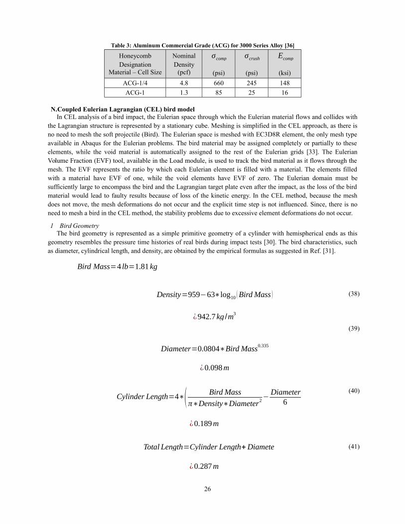
Table 3: Aluminum Commercial Grade (ACG) for 3000 Series Alloy [36]
HoneycombDesignation
Material – Cell Size
NominalDensity
(pcf)
σcomp
(psi)
σcrush
(psi)
Ecomp
(ksi)
ACG-1/4 4.8 660 245 148
ACG-1 1.3 85 25 16
N.Coupled Eulerian Lagrangian (CEL) bird modelIn CEL analysis of a bird impact, the Eulerian space through which the Eulerian material flows and collides with
the Lagrangian structure is represented by a stationary cube. Meshing is simplified in the CEL approach, as there isno need to mesh the soft projectile (Bird). The Eulerian space is meshed with EC3D8R element, the only mesh typeavailable in Abaqus for the Eulerian problems. The bird material may be assigned completely or partially to theseelements, while the void material is automatically assigned to the rest of the Eulerian grids [33]. The EulerianVolume Fraction (EVF) tool, available in the Load module, is used to track the bird material as it flows through themesh. The EVF represents the ratio by which each Eulerian element is filled with a material. The elements filledwith a material have EVF of one, while the void elements have EVF of zero. The Eulerian domain must besufficiently large to encompass the bird and the Lagrangian target plate even after the impact, as the loss of the birdmaterial would lead to faulty results because of loss of the kinetic energy. In the CEL method, because the meshdoes not move, the mesh deformations do not occur and the explicit time step is not influenced. Since, there is noneed to mesh a bird in the CEL method, the stability problems due to excessive element deformations do not occur.
1 Bird GeometryThe bird geometry is represented as a simple primitive geometry of a cylinder with hemispherical ends as this
geometry resembles the pressure time histories of real birds during impact tests [30]. The bird characteristics, suchas diameter, cylindrical length, and density, are obtained by the empirical formulas as suggested in Ref. [31].
Bird Mass=4 lb=1.81 kg
Density=959−63∗log10 (Bird Mass )
¿942.7kg /m3
Diameter=0.0804∗Bird Mass0.335
¿0.098m
(38)
(39)
Cylinder Length=4∗( Bird Mass
π∗Density∗Diameter2−Diameter
6 )¿0.189m
(40)
Total Length=Cylinder Length+Diameter
¿0.287m
(41)
26
The geometry of the bird model is shown in Figure 13.
Figure 13: Bird geometry (All dimensions are in meters)
4. Bird MaterialThe bird material is substituted by an equal mass of water, as birds mostly consist of water and air trapped in the
bones and the lungs. The bird is modeled with the Mie-Grueneisen (Us-Up) equation of state (EOS) material modelto capture the hydrodynamic response of the bird. To define the EOS material in Abaqus, only four material
properties, such as reference density (ρ0 ), Grueneisen coefficient (
Γ0 ), speed of sound (c0 ), and
material constant (s), need to be specified in Equation (6). For water, these properties are c0 = 1480 m/s,
Γ0
= 0, and s = 017, while reference density (ρ0 ) is 942.7 kg /m3 , as calculated above.
VIII. Numerical model validation
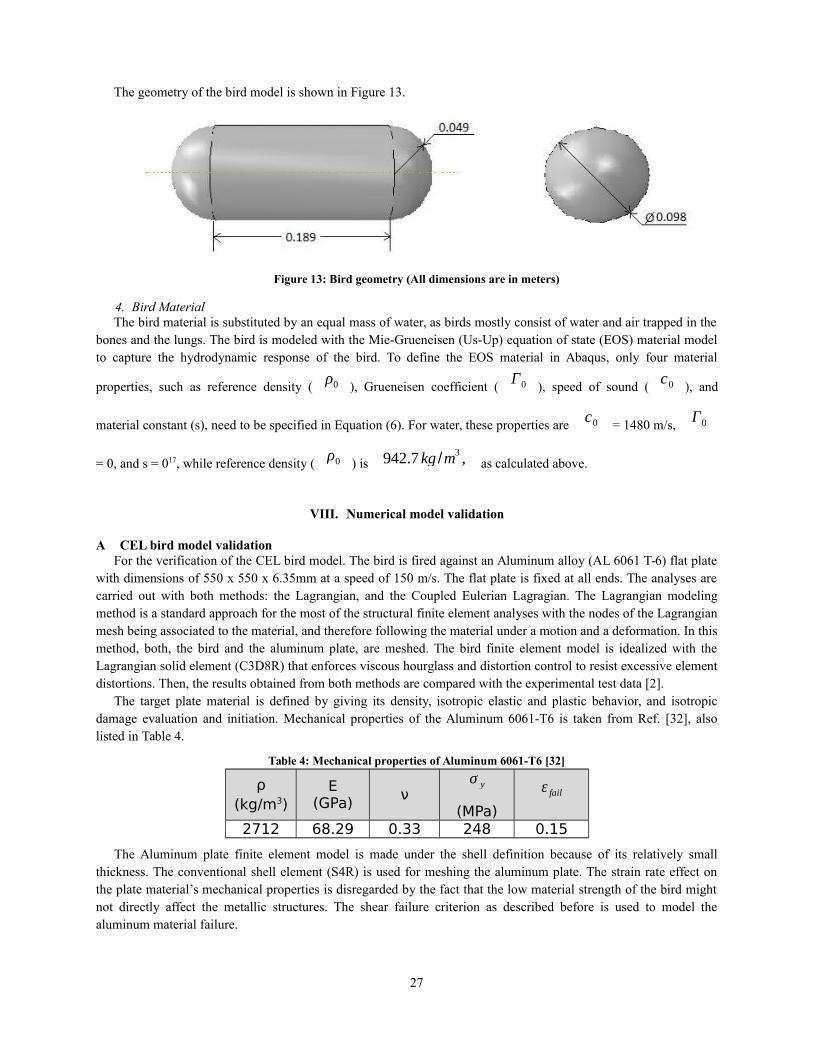
A CEL bird model validationFor the verification of the CEL bird model. The bird is fired against an Aluminum alloy (AL 6061 T-6) flat plate
with dimensions of 550 x 550 x 6.35mm at a speed of 150 m/s. The flat plate is fixed at all ends. The analyses arecarried out with both methods: the Lagrangian, and the Coupled Eulerian Lagragian. The Lagrangian modelingmethod is a standard approach for the most of the structural finite element analyses with the nodes of the Lagrangianmesh being associated to the material, and therefore following the material under a motion and a deformation. In thismethod, both, the bird and the aluminum plate, are meshed. The bird finite element model is idealized with theLagrangian solid element (C3D8R) that enforces viscous hourglass and distortion control to resist excessive elementdistortions. Then, the results obtained from both methods are compared with the experimental test data [2].
The target plate material is defined by giving its density, isotropic elastic and plastic behavior, and isotropicdamage evaluation and initiation. Mechanical properties of the Aluminum 6061-T6 is taken from Ref. [32], alsolisted in Table 4.
Table 4: Mechanical properties of Aluminum 6061-T6 [32]
ρ(kg/m3)
E(GPa)
νσ y
(MPa)
ε fail
2712 68.29 0.33 248 0.15
The Aluminum plate finite element model is made under the shell definition because of its relatively smallthickness. The conventional shell element (S4R) is used for meshing the aluminum plate. The strain rate effect onthe plate material’s mechanical properties is disregarded by the fact that the low material strength of the bird mightnot directly affect the metallic structures. The shear failure criterion as described before is used to model thealuminum material failure.
27
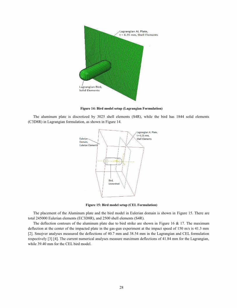
Figure 14: Bird model setup (Lagrangian Formulation)
The aluminum plate is discretized by 3025 shell elements (S4R), while the bird has 1844 solid elements(C3D8R) in Lagrangian formulation, as shown in Figure 14.
Figure 15: Bird model setup (CEL Formulation)
The placement of the Aluminum plate and the bird model in Eulerian domain is shown in Figure 15. There aretotal 245000 Eulerian elements (EC3D8R), and 2500 shell elements (S4R).
The deflection contours of the aluminum plate due to bird strike are shown in Figure 16 & 17. The maximumdeflection at the center of the impacted plate in the gas-gun experiment at the impact speed of 150 m/s is 41.3 mm[2]. Smojver analyses measured the deflections of 40.7 mm and 38.54 mm in the Lagrangian and CEL formulationrespectively [3] [4]. The current numerical analyses measure maximum deflections of 41.84 mm for the Lagrangian,while 39.40 mm for the CEL bird model.
28
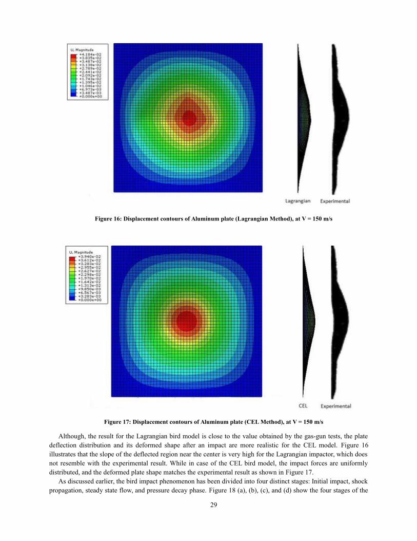
Figure 16: Displacement contours of Aluminum plate (Lagrangian Method), at V = 150 m/s
Figure 17: Displacement contours of Aluminum plate (CEL Method), at V = 150 m/s
Although, the result for the Lagrangian bird model is close to the value obtained by the gas-gun tests, the platedeflection distribution and its deformed shape after an impact are more realistic for the CEL model. Figure 16illustrates that the slope of the deflected region near the center is very high for the Lagrangian impactor, which doesnot resemble with the experimental result. While in case of the CEL bird model, the impact forces are uniformlydistributed, and the deformed plate shape matches the experimental result as shown in Figure 17.
As discussed earlier, the bird impact phenomenon has been divided into four distinct stages: Initial impact, shockpropagation, steady state flow, and pressure decay phase. Figure 18 (a), (b), (c), and (d) show the four stages of the
29
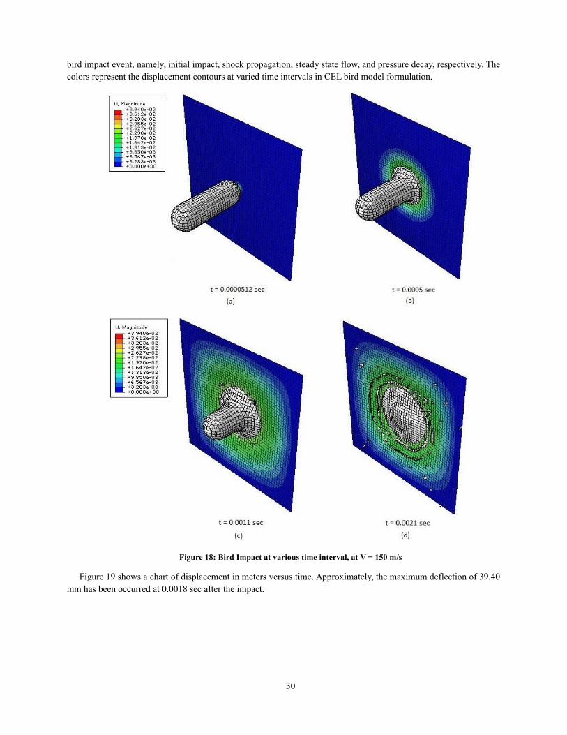
bird impact event, namely, initial impact, shock propagation, steady state flow, and pressure decay, respectively. Thecolors represent the displacement contours at varied time intervals in CEL bird model formulation.
Figure 18: Bird Impact at various time interval, at V = 150 m/s
Figure 19 shows a chart of displacement in meters versus time. Approximately, the maximum deflection of 39.40mm has been occurred at 0.0018 sec after the impact.
30
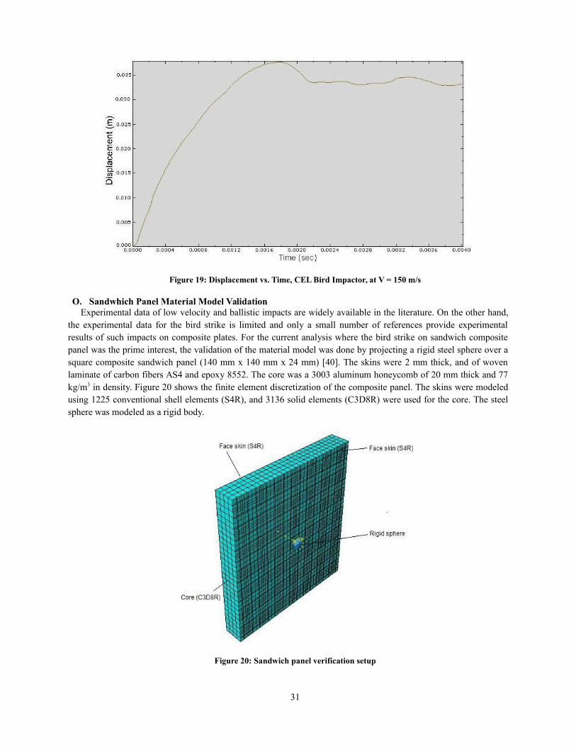
Figure 19: Displacement vs. Time, CEL Bird Impactor, at V = 150 m/s
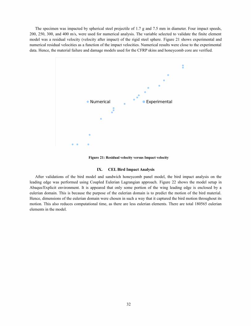
O. Sandwhich Panel Material Model ValidationExperimental data of low velocity and ballistic impacts are widely available in the literature. On the other hand,
the experimental data for the bird strike is limited and only a small number of references provide experimentalresults of such impacts on composite plates. For the current analysis where the bird strike on sandwich compositepanel was the prime interest, the validation of the material model was done by projecting a rigid steel sphere over asquare composite sandwich panel (140 mm x 140 mm x 24 mm) [40]. The skins were 2 mm thick, and of wovenlaminate of carbon fibers AS4 and epoxy 8552. The core was a 3003 aluminum honeycomb of 20 mm thick and 77kg/m3 in density. Figure 20 shows the finite element discretization of the composite panel. The skins were modeledusing 1225 conventional shell elements (S4R), and 3136 solid elements (C3D8R) were used for the core. The steelsphere was modeled as a rigid body.
Figure 20: Sandwich panel verification setup
31
The specimen was impacted by spherical steel projectile of 1.7 g and 7.5 mm in diameter. Four impact speeds,200, 250, 300, and 400 m/s, were used for numerical analysis. The variable selected to validate the finite elementmodel was a residual velocity (velocity after impact) of the rigid steel sphere. Figure 21 shows experimental andnumerical residual velocities as a function of the impact velocities. Numerical results were close to the experimentaldata. Hence, the material failure and damage models used for the CFRP skins and honeycomb core are verified.
Numerical Experimental
Figure 21: Residual velocity versus Impact velocity
IX. CEL Bird Impact Analysis
After validations of the bird model and sandwich honeycomb panel model, the bird impact analysis on theleading edge was performed using Coupled Eulerian Lagrangian approach. Figure 22 shows the model setup inAbaqus/Explicit environment. It is appeared that only some portion of the wing leading edge is enclosed by aeulerian domain. This is because the purpose of the eulerian domain is to predict the motion of the bird material.Hence, dimensions of the eulerian domain were chosen in such a way that it captured the bird motion throughout itsmotion. This also reduces computational time, as there are less eulerian elements. There are total 180565 eulerianelements in the model.
32
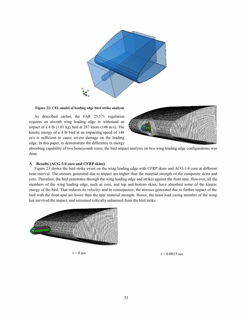
Figure 22: CEL model of leading edge bird strike analysis
As described earlier, the FAR 25.571 regulationrequires an aircraft wing leading edge to withstand animpact of a 4 lb (1.81 kg) bird at 287 knots (148 m/s). Thekinetic energy of a 4 lb bird at an impacting speed of 148m/s is sufficient to cause severe damage on the leadingedge. In this paper, to demonstrate the difference in energyabsorbing capability of two honeycomb cores, the bird impact analysis on two wing leading edge configurations wasdone.
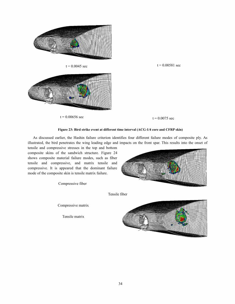
A Results (ACG-1/4 core and CFRP skins)Figure 23 shows the bird strike event on the wing leading edge with CFRP skins and ACG-1/4 core at different
time interval. The stresses generated due to impact are higher than the material strength of the composite skins andcore. Therefore, the bird penetrates through the wing leading edge and strikes against the front spar. However, all themembers of the wing leading edge, such as core, and top and bottom skins, have absorbed some of the kineticenergy of the bird. That reduces its velocity, and in consequence, the stresses generated due to further impact of thebird with the front spar are lower than the spar material strength. Hence, the main load caring member of the winghas survived the impact, and remained critically unharmed from the bird strike.
t = 0 sec
33
t = 0.0015 sec
t = 0.0045 sec
t = 0.00656 sec
Figure 23: Bird strike event at different time interval (ACG-1/4 core and CFRP skin)
As discussed earlier, the Hashin failure criterion identifies four different failure modes of composite ply. Asillustrated, the bird penetrates the wing leading edge and impacts on the front spar. This results into the onset oftensile and compressive stresses in the top and bottomcomposite skins of the sandwich structure. Figure 24shows composite material failure modes, such as fibertensile and compressive, and matrix tensile andcompressive. It is appeared that the dominant failuremode of the composite skin is tensile matrix failure.
Compressive fiber
Tensile fiber
Compressive matrix
Tensile matrix
34
t = 0.00581 sec
t = 0.0075 sec
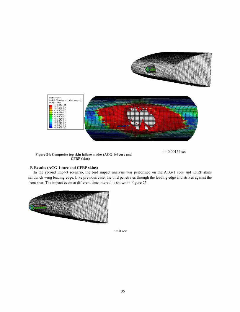
Figure 24: Composite top skin failure modes (ACG-1/4 core andCFRP skins)
P. Results (ACG-1 core and CFRP skins)In the second impact scenario, the bird impact analysis was performed on the ACG-1 core and CFRP skins
sandwich wing leading edge. Like previous case, the bird penetrates through the leading edge and strikes against thefront spar. The impact event at different time interval is shown in Figure 25.
t = 0 sec
35
t = 0.00154 sec

36

37
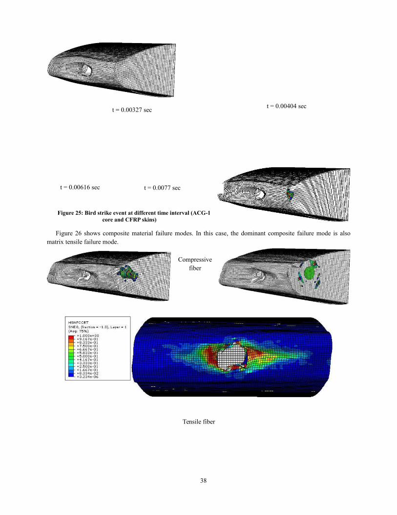
t = 0.00327 sec
Figure 25: Bird strike event at different time interval (ACG-1core and CFRP skins)
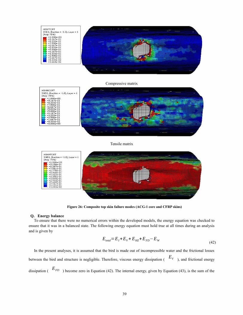
Figure 26 shows composite material failure modes. In this case, the dominant composite failure mode is alsomatrix tensile failure mode.
Compressivefiber
Tensile fiber
38
t = 0.00404 sec
t = 0.0077 sec t = 0.00616 sec
Compressive matrix
Tensile matrix
Figure 26: Composite top skin failure modes (ACG-1 core and CFRP skins)
Q. Energy balanceTo ensure that there were no numerical errors within the developed models, the energy equation was checked to
ensure that it was in a balanced state. The following energy equation must hold true at all times during an analysisand is given by
Etotal=E I+EV+EKE+EFD−EW(42)
In the present analyses, it is assumed that the bird is made out of incompressible water and the frictional losses
between the bird and structure is negligible. Therefore, viscous energy dissipation (EV ), and frictional energy
dissipation (EFD ) become zero in Equation (42). The internal energy, given by Equation (43), is the sum of the
39
recoverable elastic strain energy (EE ), the energy dissipation through plasticity (
EP ), the energy dissipation
through viscoelasticity or creep (ECD ), and the artificial strain energy (
EA ).
E I=EE+EP+ECD+EA(43)
The artificial strain energy is the energy associated with solid and shell elements undergoing hourglass modes ofdeformation. Since hourglassing is a purely numerical occurrence having no corresponding physical phenomenon. Itis important that the size of the hourglass energy term remain very small relative to the overall system energythroughout a simulation. If hourglass energy becomes a significant portion of the overall system energy balance, thisis an indication that non-physical phenomena are unduly influencing the simulation. In such situations, the resultsshould be regarded as potentially unreliable.
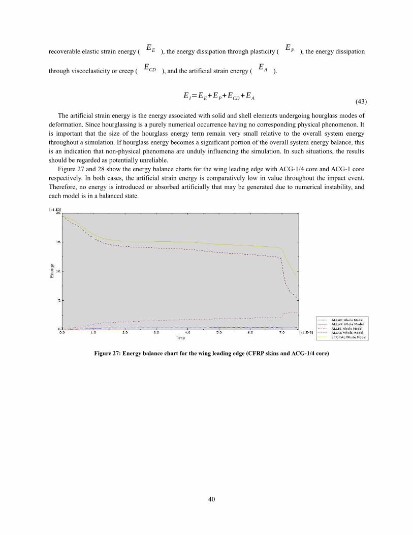
Figure 27 and 28 show the energy balance charts for the wing leading edge with ACG-1/4 core and ACG-1 corerespectively. In both cases, the artificial strain energy is comparatively low in value throughout the impact event.Therefore, no energy is introduced or absorbed artificially that may be generated due to numerical instability, andeach model is in a balanced state.
Figure 27: Energy balance chart for the wing leading edge (CFRP skins and ACG-1/4 core)
40
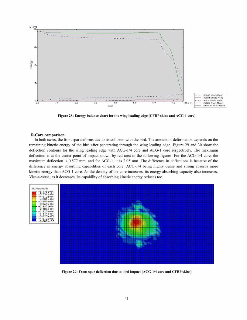
Figure 28: Energy balance chart for the wing leading edge (CFRP skins and ACG-1 core)
R.Core comparisonIn both cases, the front spar deforms due to its collision with the bird. The amount of deformation depends on the
remaining kinetic energy of the bird after penetrating through the wing leading edge. Figure 29 and 30 show thedeflection contours for the wing leading edge with ACG-1/4 core and ACG-1 core respectively. The maximumdeflection is at the center point of impact shown by red area in the following figures. For the ACG-1/4 core, themaximum deflection is 0.577 mm, and for ACG-1, it is 2.05 mm. The difference in deflections is because of thedifference in energy absorbing capabilities of each core. ACG-1/4 being highly dense and strong absorbs morekinetic energy than ACG-1 core. As the density of the core increases, its energy absorbing capacity also increases.Vice-a-versa, as it decreases, its capability of absorbing kinetic energy reduces too.
Figure 29: Front spar deflection due to bird impact (ACG-1/4 core and CFRP skins)
41
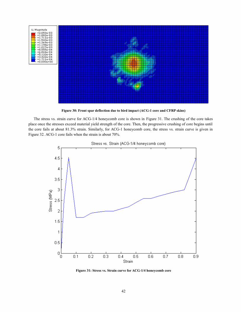
Figure 30: Front spar deflection due to bird impact (ACG-1 core and CFRP skins)
The stress vs. strain curve for ACG-1/4 honeycomb core is shown in Figure 31. The crushing of the core takesplace once the stresses exceed material yield strength of the core. Then, the progressive crushing of core begins untilthe core fails at about 81.3% strain. Similarly, for ACG-1 honeycomb core, the stress vs. strain curve is given inFigure 32. ACG-1 core fails when the strain is about 70%.
Figure 31: Stress vs. Strain curve for ACG-1/4 honeycomb core
42
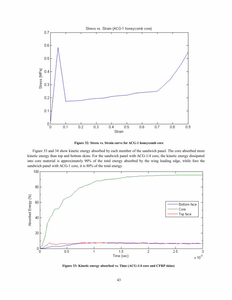
Figure 32: Stress vs. Strain curve for ACG-1 honeycomb core
Figure 33 and 34 show kinetic energy absorbed by each member of the sandwich panel. The core absorbed morekinetic energy than top and bottom skins. For the sandwich panel with ACG-1/4 core, the kinetic energy dissipatedinto core material is approximately 90% of the total energy absorbed by the wing leading edge, while fore thesandwich panel with ACG-1 core, it is 80% of the total energy.
Figure 33: Kinetic energy absorbed vs. Time (ACG-1/4 core and CFRP skins)
43
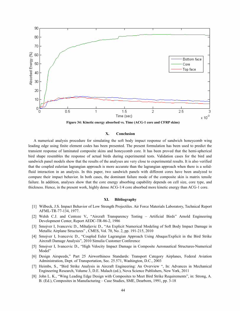
Figure 34: Kinetic energy absorbed vs. Time (ACG-1 core and CFRP skins)
X. Conclusion
A numerical analysis procedure for simulating the soft body impact response of sandwich honeycomb wingleading edge using finite element codes has been presented. The present formulation has been used to predict thetransient response of laminated composite skins and honeycomb core. It has been proved that the hemi-sphericalbird shape resembles the response of actual birds during experimental tests. Validation cases for the bird andsandwich panel models show that the results of the analyses are very close to experimental results. It is also verifiedthat the coupled eulerian lagrangian approach is more accurate than the lagrangian approach when there is a solid-fluid interaction in an analysis. In this paper, two sandwich panels with different cores have been analyzed tocompare their impact behavior. In both cases, the dominant failure mode of the composite skin is matrix tensilefailure. In addition, analyses show that the core energy absorbing capability depends on cell size, core type, andthickness. Hence, in the present work, highly dense ACG-1/4 core absorbed more kinetic energy than ACG-1 core.
XI. Bibliography
[1] Wilbeck, J.S. Impact Behavior of Low Strength Projectiles. Air Force Materials Laboratory, Technical ReportAFML-TR-77-134, 1977.
[2] Welsh C.J. and Centoze V., “Aircraft Transparency Testing – Artificial Birds” Arnold EngineeringDevelopment Center, Report AEDC-TR-86-2, 1986
[3] Smojver I, Ivancevic D., Mihaljevic D., “An Explicit Numerical Modeling of Soft Body Impact Damage inMetallic Airplane Structures” , CMES, Vol. 70, No. 2, pp. 191-215, 2010
[4] Smojver I, Ivancevic D., “Coupled Euler Lagrangian Approach Using Abaqus/Explicit in the Bird StrikeAircraft Damage Analysis”, 2010 Simulia Customer Conference
[5] Smojver I, Ivancevic D., “High Velocity Impact Damage in Composite Aeronautical Structures-NumericalModel”
[6] Design Airspeeds,” Part 25 Airworthiness Standards: Transport Category Airplanes, Federal AviationAdministration, Dept. of Transportation, Sec. 25.571, Washington, D.C., 2003
[7] Heimbs, S., “Bird Strike Analysis in Aircraft Engineering: An Overview “, In: Advances in MechanicalEngineering Research, Volume 3, D.E. Malach (ed.), Nova Science Publishers, New York, 2011
[8] John L. K., “Wing Leading Edge Design with Composites to Meet Bird Strike Requirements”, in: Strong, A.B. (Ed.), Composites in Manufacturing – Case Studies, SME, Dearborn, 1991, pp. 3-18
44
[9] Airoldi A., and B. Cacchione, “Modeling of Impact Forces and Pressures in Lagrangian Bird StrikeAnalyses”, International Journal of Impact Engineering, no. 32, pp. 1651-1677, 2006
[10] McCarthy M.A, Xiao J.R., Petrinic N, Kamoulakos A. and Melito. A " Modeling of bird Strike on an AircraftWing Leading Edge Made from Fiber Metal Laminates - Part 1: Material Modeling", Applied CompositeMaterials 11: 295-315, 2004
[11] Erkan Kirtil, Dieter Pestal, Alexander Kollofrath, Nils Gansicke, Josef Mendler, "Simulating the ImpactBehavior of Composite Aircraft Structures", 2003 Abaqus Users Conference
[12] Villanueva G. R., Cantwell W. J., “The high velocity impact response of composite and FML – reinforcedsandwich structures”, The University of Liverpool, Liverpool, UK, 2003
[13] Vaidya UK, Nelson S., Sinn B., Mathew B., ‘’Processing and high strain rate impact response of multi-funtional sandwich composites’’, Compos Struct 2001;52:429-40
[14] Harte AM, Fleck NA, Ashby MF, “Sandwich panel design using aluminum alloy foam”, AdvancedEngineering Materials 2000; 2(4):219-22
[15] McCormack TM, Miller R, Kesler O, Gibson LG, “Failure of sandwich beams with metallic foam cores”,International Journal of Solids and Structures 2001;38:4901-20
[16] Kunimoto T, Mori N. Study on the buffer characteristics of the corrugated-core used for the 5051 aluminumalloy sandwich construction under dynamic loading. J Light Met 1989; 39 (10): 687–92
[17] Chizari, M., L.M. Barrett and S.T.S Al-Hassani, "An Explicit Numerical Modelling of the Water Jet TubeFormin’’, Computational Materials Science, no. 45, pp. 378-384, 2009
[18] John O’Callaghan, “Bird-Strike Certification Standards and Damage Mitigation”, National TransportationSafetry Board (NTSB) report
[19] Georgiadis S, Gunnion AJ, Thomson RS, Cartwright BK, ‘’Bird-strike simulation for certification of theBoeing 787 composite moveable trailing edge’’, Compos Struct 2008;86:258–68
[20] Understanding and reducing bird and other wildlife hazards to Aircrafts, Bird Strike Committee USA, 2009
[21] Aktay L, Johnson AF, Holzapfel M., ‘’Prediction of impact damage on sandwich composite panels’’, ComputMater Sci 2005; 32: 252-60
[22] National Aerospace Laboratory, Technical report, ‘’Design and Testing of a Composite Birdstrike resistantleading edge’’, SAMPE Europe Conference & Exhibition, Paris, France, April 2003
[23] ‘’LS Dyna User manual V971’’, Livermore Software Technology Corporation, 2009
[24] Peterson R. L., and Barber J. P., ‘’Bird Impact Forces in Aircraft Windshield Design’’, Report # AFFDL –TR-75-150, March, 1976
[25] A publication of shock and vibration information center, U.S. Naval Research Laboratory, Washington D.C:The shock and Vibration bulletin, 1978
[26] Baughn T. N., and Graham L. W., ‘’Simulation of Birdstrike Impact on Aircraft Canopy Material’’, Journal ofAircraft, Vol. 25, No. 7, pp 659-664, July 1988
[27] Hallquist J. O., Theoretical Manual, Livermore Software Technology Corporation, March, 2006
[28] Belytschko T., Liu W. K., and Moran B., ‘’Nonlinear Finite Elements for Continua and Structure’’, JohnWiley & Sons Ltd., 2000
[29] Brockman R. A., and Held T. W., ’’Explicit Finite Element Method for Transparency Impact Analysis’’,University of Dayton Research Institute, Dayton, Ohio, June 1991
[30] Johnson AF, Holzapfel M., ‘’Modeling soft body impact on composite structures’’, Compos Struct2003;63:103-13
[31] Research Paper, ‘’The Hazard Posed to Aircraft by Birds’’, Australian Transport Safety Bureau, 2002
[32] Metallic materials and elements for aerospace vehicle strcutures, MIL-HDBK-5, Department of DefenceHandbook, Washington D.C: 2003
[33] Abaqus analysis user’s manual, Version 6.11. Dassault Systemes; 2011
[34] Abrate S. Impact on composite structures. Cambridge: Cambridge University Press; 1998. P.242-57[35] Hexcel Corporation, “Honeycomb Sandwich Design Technology”, Dublin, CA, USA[36] Hexcel Corporation, “Honeycomb Attributes and Properties”, Dublin, CA, USA[37] Wahl, L.; Maas, S.; Waldmann, D.; Zurbes, A.; Freres, P., “Shear stresses in honeycomb sandwich plates:
Analytical solution, finite element method and experimental verification”, Journal of Sandwich Structuresand Materials 14 (4): 449-468
45
[38] V. Mollon, J. Bonhomme, J. Vina, A. Arguelles, A. Fernandez-Canteli, “Influence of the principal tensilestresses on delamination fracture mechanisms and their associated morphology for different loading modes incarbon/epoxy composites”
[39] M. Meo, R. Vignjevic, G. Marengo, “The response of honeycomb sandwich panels under low-velocity impactloading”
[40] Brenda L. Buitrago, Carlos Santiuste, Sonia Sanchez-Saez, Enrique Barbero, Carlos Navarro, “Modeling ofcomposite sandwich structures with honeycomb core subjected to high velocity impact”
[41] FAA Special Project Number SP4614WI-Q, “Hexcel 8552 AS4 Unidirectional Prepreg at 190 gsm & 35% RCQualification Material Property Data Report”, NCAMP Test Report Number CAM-RP-2010-002, Rev A
[42] National Aeronautics and Space Administration, “A study of failure criteria of fibrous compositematerials”, NASA/CR-2001-210661, March 2001
46