Embed Size (px)
Citation preview
B. Iyer, S. Nalbalwar and R. Pawade (Eds.)
ICCASP/ICMMD-2016. Advances in Intelligent Systems Research.
Vol. 137, Pp. 212-219.
© 2017. The authors - Published by Atlantis Press This is an open access article under the CC BY-NC license (http://creativecommons.org/licens)es/by-nc/4.0/).
Numerical and Experimental Studies on Fixture-Workpiece
Contact and Structural Deformations in Pocket Milling
M. Yadav1*
, S. Mohite2
1Research Scholar, Government College of Engineering, Karad,India
2Professor, Government College of Engineering, Karad, India
Abstract:Geometrical inaccuracies, in a statically clampedworkpiece subjected to cutting forces,aremainly
caused by the contact deformationsat the locators and the structural deformations in the body of the
workpiece.In addition, during machining the structural deformations continuously increase as the workpiece
keeps losing its stiffness on account of metal removal. This condition is also encountered while machining thin
walled workpieces. To investigate the relative significance of the structural and the contact deformations,fixture
elements workpieceand the contact at their interface is modelled numerically in ANSYS 17.2.A milling fixture
with 3-2-1 location principle and two hydraulically operated clamps is developed for pocket milling operation
on Al-6061-T6 and a number of experiments are conducted to obtain structural deformation of workpiece. The
numerical simulations and experiments were performed for different percentages of metal removal (0%, 20%
and 50%) under various clamping pressures varying from 15-25 bar (kg/cm2).The numerically predicted
deformations show a good agreement with experimental results. The studies would help in developing an
adaptive clamping mechanism to compensate for the changing structural stiffness of the workpiece and thereby
keeping a check on the deformations, and hence the machining accuracies.
Keywords: Hertzian contact, workpiece compliance, fixture-workpiece, adaptive clamping, metal removal effect
1 Introduction
After successful integration of fixture design and analysis with CAD/CAM, Computer Aided Fixture Design
Systems (CAFD) is progressing towards integration of hardware elements (mainly sensors and actuators) in the
fixture combined with the necessary control algorithms to realize intelligent fixtures [1,2].The common
functions of fixtures are improved from only securely holding and accurately locating the workpiece considered
as a rigid body, to integrate additional functions taking into account aspects like the deformations, vibrations
and distortions in the workpiece during processing as a consequence of the variations in the dynamic behaviour
of the fixture workpiece system.
A good fixture design provides positional accuracy, workpiece stability and an acceptable workpiece
deformation and displacement, during machining. In order to meet high production demands, the high metal
removal rates and high clamping forces become inevitable. Clamping forces play an important role in
determining the workpiece stability and accuracy. The clamping force applied must be large enough to restrain
the workpiece motion completely during machining. Localized contact forces are developed due to clamping
forces at contact interfaces. Excessive contact forces cause elastic or plastic deformations of workpiece at
contact regions and insufficient contact forces cause slip or lift-off at the workpiece and locators/ clamps
interface[3]. Therefore, it is necessary to study the effect of the clamping force on the overall workpiece
deformations [4]. Siebenaler et al., investigated the effects of various finite element modelling parameters, such
as friction and meshdensity, on workpiece deformation. In addition to modelling the workpiece and fixture tips,
as is common, the effect of compliance of other fixture components such as support blocks, base plate, etc., on
workpiece deformation is also examined in this work. The FEA predictions of workpiece deformationand
locator reactions are experimentally verified [5].The layout of fixture including clamp and locator layout play an
important role in fixture performance. Vishnuprian et al. suggested fixture layout optimization by taking into
consideration the effect locator errors.The study presented deterministic location ensured throughout the
optimization process and minimal machining errors [6].
Numerical and Experimental Studies on Workpiece Deformation 213
During machining, workpiece experiences motion due to cutting and clamping forces. This affects the location
accuracy and final part quality to a considerable extent.Jamdar et al. presented tracking of workpiece stability
under spatially varying cutter position and continuouslydecreasing mass and compliance of a workpiece during
pocket milling operation [7]. Adaptive clamping or varying cutting parameters is the remedial measure to
control the workpiece deformations.With this objective, in this paper,the workpiece deformations are tracked
under varying clamping pressures and different percentages of metal removal during pocket milling operation.
In the following sections, analytical model based on Hertzian contact theory is presented to estimate contact
deformations, this is followed by numerical predictions and experimental measurements.
2 Analytical model
The analytical model is based on the Hertzian contact theory. The workpiece remains in static equilibrium under
the action of clamps and its own weight. The elastic deformation of the workpiece occurs at a fixture-workpiece
contact due to clamping forces and reactions at the locators. Therefore the contact reaction force must be known.
For this, the principle of minimum total complementary energy is applied to develop a model that gives the
reaction force at each fixture-workpiece contact. The complementary energy of fixture-workpiece contacts can
be computed from the contact force-displacement relationships, as given in the contact mechanics literature. A
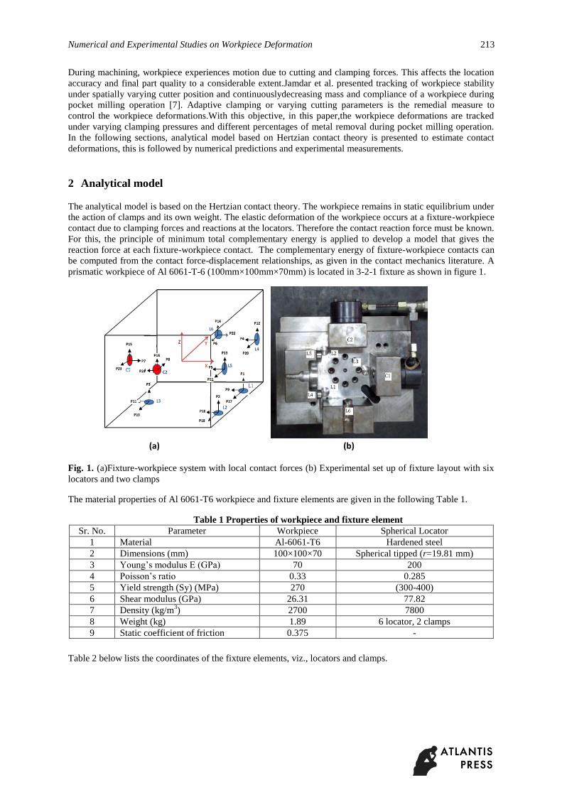
prismatic workpiece of Al 6061-T-6 (100mm×100mm×70mm) is located in 3-2-1 fixture as shown in figure 1.
(a) (b)
Fig. 1. (a)Fixture-workpiece system with local contact forces (b) Experimental set up of fixture layout with six
locators and two clamps
The material properties of Al 6061-T6 workpiece and fixture elements are given in the following Table 1.
Table 1 Properties of workpiece and fixture element
Sr. No. Parameter Workpiece Spherical Locator
1 Material Al-6061-T6 Hardened steel
2 Dimensions (mm) 100×100×70 Spherical tipped (r=19.81 mm)
3 Young’s modulus E (GPa) 70 200
4 Poisson’s ratio 0.33 0.285
5 Yield strength (Sy) (MPa) 270 (300-400)
6 Shear modulus (GPa) 26.31 77.82
7 Density (kg/m3) 2700 7800
8 Weight (kg) 1.89 6 locator, 2 clamps
9 Static coefficient of friction 0.375 -
Table 2 below lists the coordinates of the fixture elements, viz., locators and clamps.
214 Yadav and Mohite
Table 2 Layout of fixture element
Abrief outline of the Hertzian contact theory is given below. First, the contact radius is obtained as follows.
(1)
- Relative curvature at contact
with is the local radius of the workpiece and is the radius
of the spherical tip.
(2)
The total complementary energy for all (L+C) contact is written as
(3)
To find the reaction forces complementary energy equation for the assemblage of clamps, locators and
workpiece is minimized under the constraints. Thus, the objective function is minimization of the total
complementary energy at contact.
(4)
Subjected to: Linear constraint and nonlinear constraint
and (5a)
(5b)
( =1, 2……L+C) (5c)
(5d)
( =1, 2…..C+1) (5e)
Solving equation (4) and (5) yields the contact reaction forces, and with =1 to (L+C).
For a spherical-tipped fixture element pressed against a curved workpiece surface, the relationship for
deformations is given by eq. (6) and (7) below,
(6)
Fixture
Element Xg(mm) Yg(mm) Zg(mm)
L1 45 45 -35
L2 45 -45 -35
L3 -45 1 -35
L4 50 40 1
L5 50 -40 1
L6 1 50 1
C1 -50 1 1
C2 1 -50 1
Numerical and Experimental Studies on Workpiece Deformation 215
for j= x or y (7)
where, and represent normal force and normal deformation. and represent tangential force and
tangential deformation.
It should be noted here that the net deformation of the workpiece consists of two components, viz., the local
contact deformation as discussed above and the structural deformation caused by workpiece compliance. The
local contact deformation is obtained quite accurately using the Hertzian contact theory discussed above;
however, there are no closed form formulae for finding out structural deformations of the workpiece. Hence, we
use numerical modelling in ANSYS is done, to obtain the contact and structural deformation as described in the
following section.
3 Numerical model
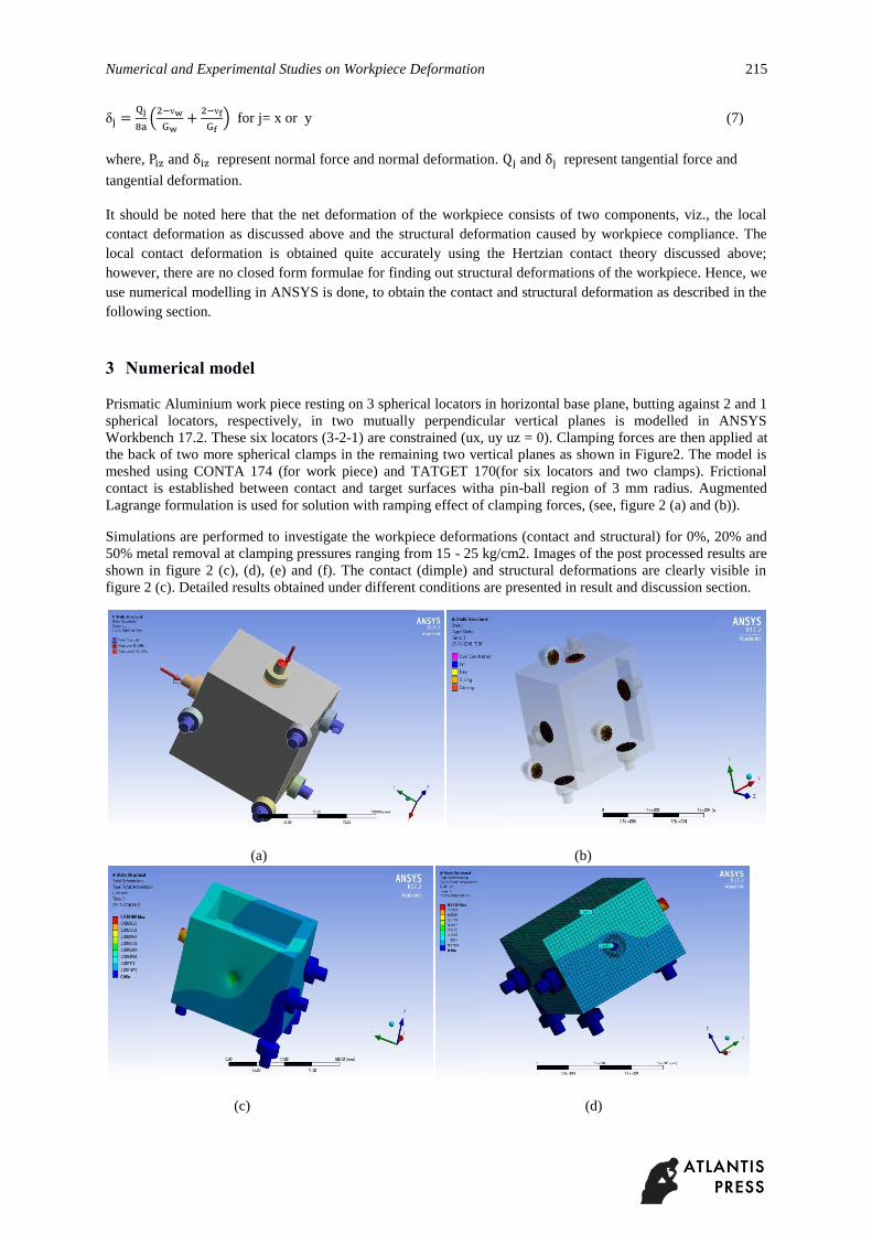
Prismatic Aluminium work piece resting on 3 spherical locators in horizontal base plane, butting against 2 and 1
spherical locators, respectively, in two mutually perpendicular vertical planes is modelled in ANSYS
Workbench 17.2. These six locators (3-2-1) are constrained (ux, uy uz = 0). Clamping forces are then applied at
the back of two more spherical clamps in the remaining two vertical planes as shown in Figure2. The model is
meshed using CONTA 174 (for work piece) and TATGET 170(for six locators and two clamps). Frictional
contact is established between contact and target surfaces witha pin-ball region of 3 mm radius. Augmented
Lagrange formulation is used for solution with ramping effect of clamping forces, (see, figure 2 (a) and (b)).
Simulations are performed to investigate the workpiece deformations (contact and structural) for 0%, 20% and
50% metal removal at clamping pressures ranging from 15 - 25 kg/cm2. Images of the post processed results are
shown in figure 2 (c), (d), (e) and (f). The contact (dimple) and structural deformations are clearly visible in
figure 2 (c). Detailed results obtained under different conditions are presented in result and discussion section.
(a) (b)
(c) (d)
216 Yadav and Mohite
(e) (f)
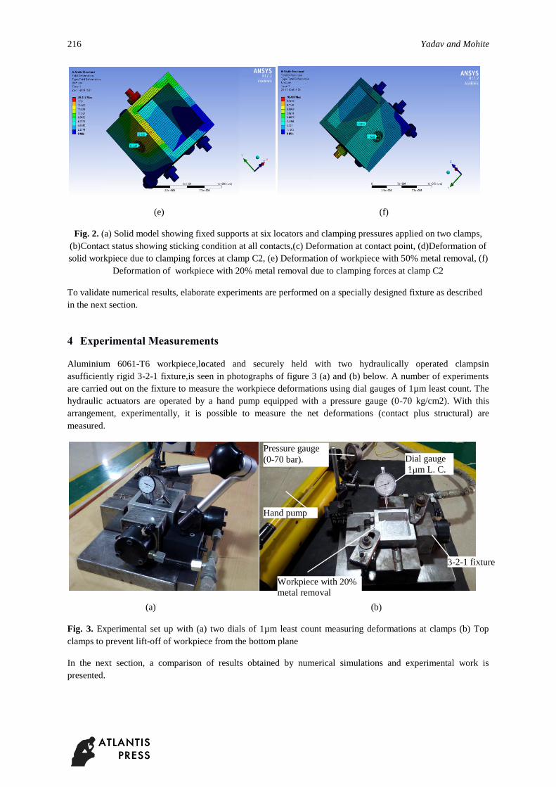
Fig. 2. (a) Solid model showing fixed supports at six locators and clamping pressures applied on two clamps,
(b)Contact status showing sticking condition at all contacts,(c) Deformation at contact point, (d)Deformation of
solid workpiece due to clamping forces at clamp C2, (e) Deformation of workpiece with 50% metal removal, (f)
Deformation of workpiece with 20% metal removal due to clamping forces at clamp C2
To validate numerical results, elaborate experiments are performed on a specially designed fixture as described
in the next section.
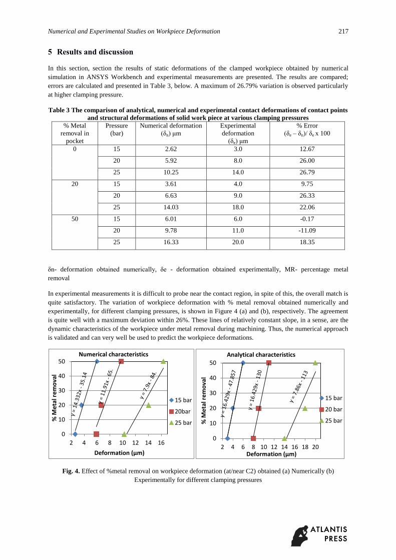
4 Experimental Measurements
Aluminium 6061-T6 workpiece,located and securely held with two hydraulically operated clampsin
asufficiently rigid 3-2-1 fixture,is seen in photographs of figure 3 (a) and (b) below. A number of experiments
are carried out on the fixture to measure the workpiece deformations using dial gauges of 1µm least count. The
hydraulic actuators are operated by a hand pump equipped with a pressure gauge (0-70 kg/cm2). With this
arrangement, experimentally, it is possible to measure the net deformations (contact plus structural) are
measured.
(a) (b)
Fig. 3. Experimental set up with (a) two dials of 1µm least count measuring deformations at clamps (b) Top
clamps to prevent lift-off of workpiece from the bottom plane
In the next section, a comparison of results obtained by numerical simulations and experimental work is
presented.
Dial gauge
1µm L. C.
Pressure gauge
(0-70 bar).
Workpiece with 20%
metal removal
Hand pump
3-2-1 fixture
Numerical and Experimental Studies on Workpiece Deformation 217
5 Results and discussion
In this section, section the results of static deformations of the clamped workpiece obtained by numerical
simulation in ANSYS Workbench and experimental measurements are presented. The results are compared;
errors are calculated and presented in Table 3, below. A maximum of 26.79% variation is observed particularly
at higher clamping pressure.
Table 3 The comparison of analytical, numerical and experimental contact deformations of contact points
and structural deformations of solid work piece at various clamping pressures
% Metal
removal in
Pressure
(bar)
Numerical deformation
( n) μm
Experimental
deformation
( e) μm
% Error
( e – n)/ e x 100
0 15 2.62 3.0 12.67
20 5.92 8.0 26.00
25 10.25 14.0 26.79
20 15 3.61 4.0 9.75
20 6.63 9.0 26.33
25 14.03 18.0 22.06
50 15 6.01 6.0 -0.17
20 9.78 11.0 -11.09
25 16.33 20.0 18.35
n- deformation obtained numerically, e - deformation obtained experimentally, MR- percentage metal
removal
In experimental measurements it is difficult to probe near the contact region, in spite of this, the overall match is
quite satisfactory. The variation of workpiece deformation with % metal removal obtained numerically and
experimentally, for different clamping pressures, is shown in Figure 4 (a) and (b), respectively. The agreement
is quite well with a maximum deviation within 26%. These lines of relatively constant slope, in a sense, are the
dynamic characteristics of the workpiece under metal removal during machining. Thus, the numerical approach
is validated and can very well be used to predict the workpiece deformations.
Fig. 4. Effect of %metal removal on workpiece deformation (at/near C2) obtained (a) Numerically (b)
Experimentally for different clamping pressures
0
10
20
30
40
50
2 4 6 8 10 12 14 16
% M
eta
l re
mo
val
Deformation (µm)
Numerical characteristics
15 bar
20bar
25 bar
0
10
20
30
40
50
2 4 6 8 10 12 14 16 18 20
% M
eta
l re
mo
val
Deformation (µm)
Analytical characteristics
15 bar
20 bar
25 bar
218 Yadav and Mohite
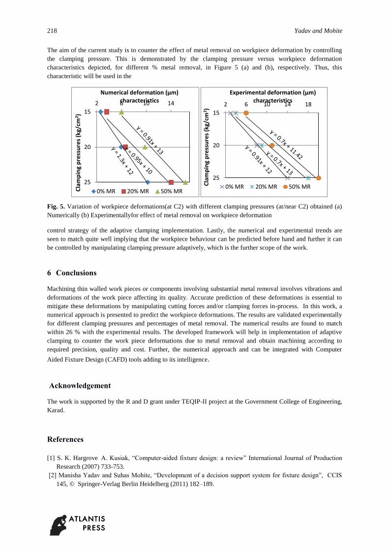
The aim of the current study is to counter the effect of metal removal on workpiece deformation by controlling
the clamping pressure. This is demonstrated by the clamping pressure versus workpiece deformation
characteristics depicted, for different % metal removal, in Figure 5 (a) and (b), respectively. Thus, this
characteristic will be used in the
Fig. 5. Variation of workpiece deformations(at C2) with different clamping pressures (at/near C2) obtained (a)
Numerically (b) Experimentallyfor effect of metal removal on workpiece deformation
control strategy of the adaptive clamping implementation. Lastly, the numerical and experimental trends are
seen to match quite well implying that the workpiece behaviour can be predicted before hand and further it can
be controlled by manipulating clamping pressure adaptively, which is the further scope of the work.
6 Conclusions
Machining thin walled work pieces or components involving substantial metal removal involves vibrations and
deformations of the work piece affecting its quality. Accurate prediction of these deformations is essential to
mitigate these deformations by manipulating cutting forces and/or clamping forces in-process. In this work, a
numerical approach is presented to predict the workpiece deformations. The results are validated experimentally
for different clamping pressures and percentages of metal removal. The numerical results are found to match
within 26 % with the experimental results. The developed framework will help in implementation of adaptive
clamping to counter the work piece deformations due to metal removal and obtain machining according to
required precision, quality and cost. Further, the numerical approach and can be integrated with Computer
Aided Fixture Design (CAFD) tools adding to its intelligence.
Acknowledgement
The work is supported by the R and D grant under TEQIP-II project at the Government College of Engineering,
Karad.
References
[1] S. K. Hargrove A. Kusiak, “Computer-aided fixture design: a review” International Journal of Production
Research (2007) 733-753.
[2] Manisha Yadav and Suhas Mohite, “Development of a decision support system for fixture design”, CCIS
145, © Springer-Verlag Berlin Heidelberg (2011) 182–189.
15
20
25
2 6 10 14
Cla
mp
ing
pre
ssu
res
(kg/
cm2 )
Numerical deformation (µm) characteristics
0% MR 20% MR 50% MR
15
20
25
2 6 10 14 18
Cla
mp
ing
pre
ssu
res
(kg/
cm2)
Experimental deformation (µm) characteristics
0% MR 20% MR 50% MR

Numerical and Experimental Studies on Workpiece Deformation 219
[3] James N. Asante, “A combined contact elasticity and finite element-based modelfor contact load and
pressure distribution calculationin a frictional workpiece-fixture system” International Journal Advanced
Manufacturing Technology (2008) 39:578–588
[4] Haiyan Deng, “Analysis and synthesis of fixturing dynamic stability in machining accounting formaterial
removal effect”, A Ph. D thesis submitted to the Georgia Institute of Technology Atlanta, Georgia, (2006)
[5] Shane P. Siebenaler, Shreyes N. Melkote, “Prediction of workpiece deformation in a fixture systemusing the
finite element method” International Journal of Machine Tools and Manufacture 46 (2006) 51–58
[6] Vishnuprian et al., “Optimization of machining fixture layout for tolerance requirements under the influence
of locating errors” International Journal of Engineering, Science and TechnologyVol. 2, No. 1, (2010) 152-
162
[7] Jamdar S.B. et al., “Tracking workpiece stability under varying cutter positions, mass and compliance of
workpiece in pocket milling”, International Journal of Research in Engineering and Technology, Vol. 5,
Special Issue: 13, (2016) 132-138