Embed Size (px)
Citation preview
DO NOT ATTEMPT INSTALLING THIS HRV WITHOUT FIRST READING THIS ENTIRE MANUAL
- NOT FOR OUTSIDE USE -
Summeraire Mfg. Peterborough, Ontario,
Canada, K9J 6X6
NUWAVE SERIESResidential
Central Heat Recovery VentilatorProduct Specifications
andInstallation and User Manual
NuWave SeriesModels
NW130, NW140, NW220, NW260
APPLICATION WARNINGIt is always important to assess how the operation of any
Heat Recovery Ventilator (HRV) may interact with vented combustion equipment (i.e. gas furnaces, oil furnaces, wood stoves, fireplaces. etc.)
Never install an HRV in a situation where it’s normal operation, lack of operation, or partial failure may result in the back drafting on vented combustion equipment
such as water heaters, furnaces and fireplaces.
NUWAVE®
Built Better To Last Longer
BY:
2
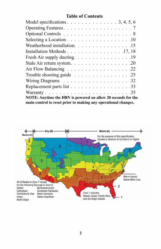
Table of Contents Model specifications . . . . . . . . . . . . . . 3, 4, 5, 6Operating Features . . . . . . . . . . . . . . . . . . . 7Optional Controls . . . . . . . . . . . . . . . . . . . 8Selecting a Location . . . . . . . . . . . . . . . . . .10Weatherhood installation. . . . . . . . . . . . . . . .15Installation Methods . . . . . . . . . . . . . . . .17, 18Fresh Air supply ducting . . . . . . . . . . . . . . . .19Stale Air return system. . . . . . . . . . . . . . . . .20Air Flow Balancing . . . . . . . . . . . . . . . . . .22Trouble shooting guide . . . . . . . . . . . . . . . .25Wiring Diagrams . . . . . . . . . . . . . . . . . . .32Replacement parts list . . . . . . . . . . . . . . . . .33 Warranty . . . . . . . . . . . . . . . . . . . . . . . .35NOTE: Anytime the HRV is powered on allow 20 seconds for the main control to reset prior to making any operational changes.
3
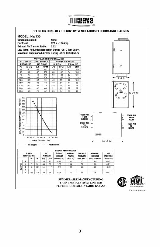
SPECIFICATIONS HEAT RECOVERY VENTILATORS PERFORMANCE RATINGS
ENERGY PERFORMANCESUPPLY
TEMPERATURENET
AIR FLOWSUPPLY/EXHAUST
FLOW RATIO
AVERAGE POWER(WATTS)
SENSIBLE RECOVERYEFFICIENCY
APPARENTSENSIBLE
EFFECTIVENESS
NETMOISTURETRANSFER°C °F L/S CFM
HEATING
i 0 32 33 70 0.92 60 65 80 0.07ii 0 32 45 96 1.00 94 61 70 0.01iii 0 32 55 117 .99 94 60 68 -0.01ivv -25 -13 30 64 0.94 71 61 76 0.07
MODEL: NW130Options Installed: NoneElectrical: 120 V - 1.5 AmpExhaust Air Transfer Ratio: 0.02 Low Temp. Reduction Reduction During -25°C Test 20.0%Maximum Unbalanced Airflow During -25°C Test: 8.5 L/s
VENTILATION PERFORMANCEEXT. STATIC NET SUPPLY GROSS AIR FLOWPRESSURE AIR FLOW SUPPLY EXHAUST
Pa in. wg L/S CFM L/S CFM L/S CFM25 0.1 67 143 70 149 70 14950 0.2 62 132 65 137 64 13675 0.3 56 118 58 123 59 125
100 0.4 49 104 51 108 54 113125 0.5 43 91 45 95 47 100150 0.6 38 80 40 84 41 86175 0.7 34 72 35 75 33 71200 0.8 30 63 31 66 27 57225 0.9 25 52 25 54 22 47
SUMMERAIRE MANUFACTURING TRENT METALS (2012) LIMITED
PETERBOROUGH, ONTARIO K9J 6X6
12 1/2 IN
19 3/4 IN.
STALE AIRTO
OUTSIDE
FRESH AIRTO
HOUSE
STALE AIRFROM HOUSE
FRESH AIRFROM
OUTSIDE
24 1/8 IN.
Net Supply Net Exhaust
Ext.
Diff
eren
tial P
ress
ure
- Pas
cals
3002752502252001751501251007550250
Gross Airflow - L/s10 20 30 40 50 60 70 80 90
NW130-SP-EN-REV3
Home Ventilating Institute
4
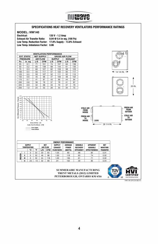
SPECIFICATIONS HEAT RECOVERY VENTILATORS PERFORMANCE RATINGS
ENERGY PERFORMANCESUPPLY
TEMPERATURENET
AIR FLOWSUPPLY/EXHAUST
FLOW RATIO
AVERAGE POWER(WATTS)
SENSIBLE RECOVERYEFFICIENCY
APPARENTSENSIBLE
EFFECTIVENESS
NETMOISTURETRANSFER°C °F L/S CFM
HEATING
i 0 32 30 63 1.03 80 68 82 0.01ii 0 32 46 98 1.00 118 63 74 0.02iii 0 32 55 118 1.00 136 61 71 0.02iv -25 -13 32 69 .91 102 59 82 0.04
MODEL: NW140Electrical: 120 V - 1.2 AmpExhaust Air Transfer Ratio: 0.04 @ 0.4 in wg. (100 Pa) Low Temp. Reduction Factor: 17.8% Supply - 13.8% ExhaustLow Temp. Imbalance Factor: 0.86
VENTILATION PERFORMANCEEXT. STATIC NET SUPPLY GROSS AIR FLOWPRESSURE AIR FLOW SUPPLY EXHUAST
Pa in. wg L/S CFM L/S CFM L/S CFM25 0.1 71 151 74 157 64 13650 0.2 65 138 68 144 61 13075 0.3 60 127 62 133 58 123
100 0.4 55 117 57 122 55 117125 0.5 50 107 52 111 52 110150 0.6 45 96 47 100 48 102175 0.7 41 87 43 90 44 94200 0.8 36 76 37 79 41 87225 0.9 32 68 33 70 37 79250 1.0 24 52 26 54 34 72
SUMMERAIRE MANUFACTURING TRENT METALS (2012) LIMITED
PETERBOROUGH, ONTARIO K9J 6X6
Gross SupplyGross Exhaust
NW140-SP-EN-REV4
14 1/4 IN.
20 IN.
STALE AIRTO
OUTSIDE
FRESH AIRTO
HOUSE
STALE AIRFROM HOUSE
FRESH AIRFROM
OUTSIDE
28 1/4 IN.
Home Ventilating Institute
5
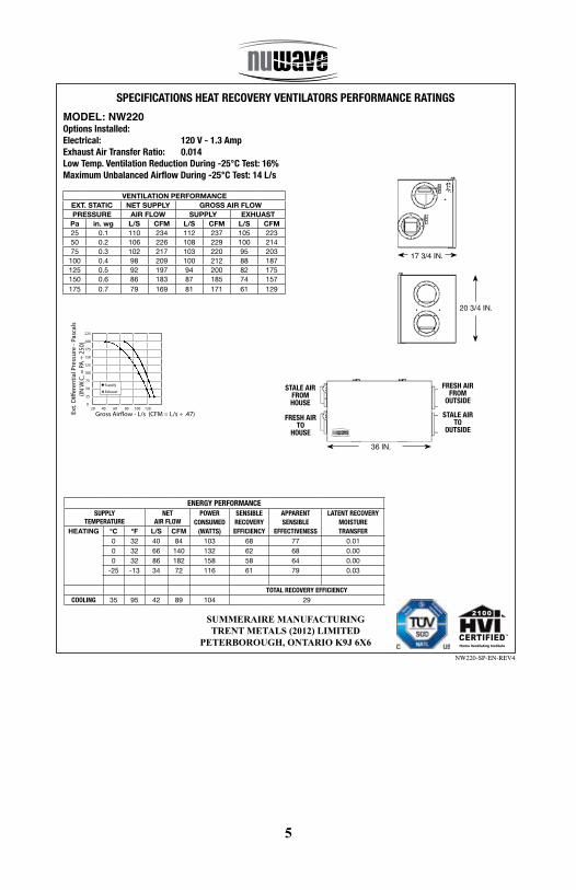
SPECIFICATIONS HEAT RECOVERY VENTILATORS PERFORMANCE RATINGS
MODEL: NW220Options Installed: Electrical: 120 V - 1.3 AmpExhaust Air Transfer Ratio: 0.014 Low Temp. Ventilation Reduction During -25°C Test: 16% Maximum Unbalanced Airflow During -25°C Test: 14 L/s
VENTILATION PERFORMANCEEXT. STATIC NET SUPPLY GROSS AIR FLOWPRESSURE AIR FLOW SUPPLY EXHUAST
Pa in. wg L/S CFM L/S CFM L/S CFM25 0.1 110 234 112 237 105 22350 0.2 106 226 108 229 100 21475 0.3 102 217 103 220 95 203
100 0.4 98 209 100 212 88 187125 0.5 92 197 94 200 82 175150 0.6 86 183 87 185 74 157175 0.7 79 169 81 171 61 129
SUMMERAIRE MANUFACTURING TRENT METALS (2012) LIMITED
PETERBOROUGH, ONTARIO K9J 6X6
225
200
175
150
125
100
75
50
25
0
20 40 60 80 100 120
Supply
Exhaust
Gross Air�ow - L/s (CFM = L/s ÷ .47)Ext.
Di�
eren
tial P
ress
ure
- Pas
cals
(IN W
.C. =
PA
÷ 2
50)
NW220-SP-EN-REV4
ENERGY PERFORMANCESUPPLY
TEMPERATURENET
AIR FLOWPOWER
CONSUMED(WATTS)
SENSIBLE RECOVERYEFFICIENCY
APPARENTSENSIBLE
EFFECTIVENESS
LATENT RECOVERYMOISTURETRANSFERHEATING °C °F L/S CFM
0 32 40 84 103 68 77 0.010 32 66 140 132 62 68 0.000 32 86 182 158 58 64 0.00
-25 -13 34 72 116 61 79 0.03
TOTAL RECOVERY EFFICIENCYCOOLING 35 95 42 89 104 29
17 3/4 IN.
20 3/4 IN.
STALE AIRTO
OUTSIDE
FRESH AIRTO
HOUSE
STALE AIRFROM HOUSE
FRESH AIRFROM
OUTSIDE
36 IN.
Home Ventilating Institute
6
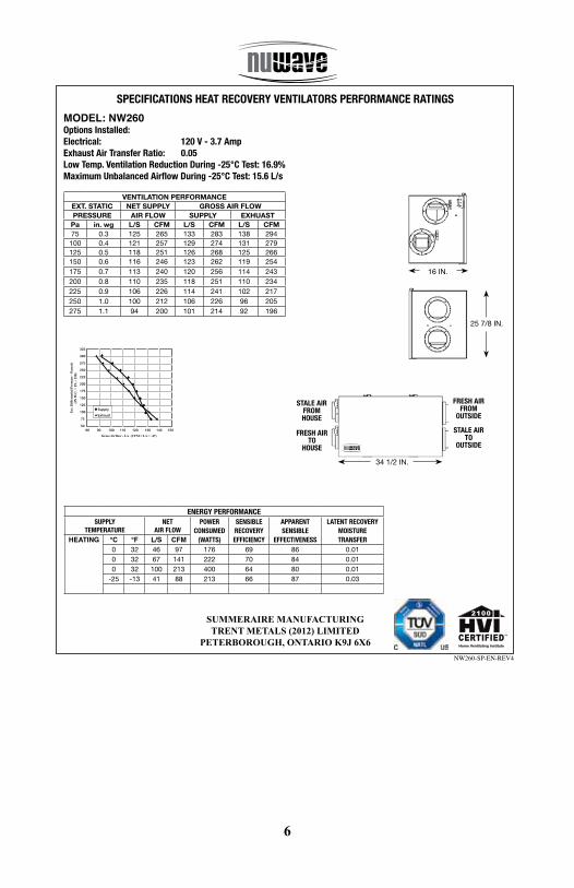
SPECIFICATIONS HEAT RECOVERY VENTILATORS PERFORMANCE RATINGS
MODEL: NW260Options Installed: Electrical: 120 V - 3.7 AmpExhaust Air Transfer Ratio: 0.05 Low Temp. Ventilation Reduction During -25°C Test: 16.9% Maximum Unbalanced Airflow During -25°C Test: 15.6 L/s
VENTILATION PERFORMANCEEXT. STATIC NET SUPPLY GROSS AIR FLOWPRESSURE AIR FLOW SUPPLY EXHUAST
Pa in. wg L/S CFM L/S CFM L/S CFM75 0.3 125 265 133 283 138 294
100 0.4 121 257 129 274 131 279125 0.5 118 251 126 268 125 266150 0.6 116 246 123 262 119 254175 0.7 113 240 120 256 114 243200 0.8 110 235 118 251 110 234225 0.9 106 226 114 241 102 217250 1.0 100 212 106 226 96 205275 1.1 94 200 101 214 92 196
SUMMERAIRE MANUFACTURING TRENT METALS (2012) LIMITED
PETERBOROUGH, ONTARIO K9J 6X6
325
300
275
250
225
200
175
150
125
100
75
50
80 90 100 110 120 130 140 150
Supply
Exhaust
Gross Airflow - L/s (CFM = L/s ÷ .47)
Ext
. Dif
fere
ntia
l Pre
ssur
e -
Pas
cals
(IN
W.C
. = P
A ÷
250
)
NW260-SP-EN-REV4
ENERGY PERFORMANCESUPPLY
TEMPERATURENET
AIR FLOWPOWER
CONSUMED(WATTS)
SENSIBLE RECOVERYEFFICIENCY
APPARENTSENSIBLE
EFFECTIVENESS
LATENT RECOVERYMOISTURETRANSFERHEATING °C °F L/S CFM
0 32 46 97 176 69 86 0.010 32 67 141 222 70 84 0.010 32 100 213 400 64 80 0.01
-25 -13 41 88 213 66 87 0.03
16 IN.
25 7/8 IN.
STALE AIRTO
OUTSIDE
FRESH AIRTO
HOUSE
STALE AIRFROM HOUSE
FRESH AIRFROM
OUTSIDE
34 1/2 IN.
Home Ventilating Institute
7
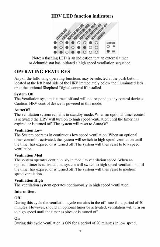
Note: a flashing LED is an indication that an external timer or dehumidistat has initiated a high speed ventilation sequence.
HRV LED function indicators
OpERATiNg FEATuREsAny of the following operating functions may be selected at the push button located at the left hand side of the HRV immediately below the illuminated leds, or at the optional Shepherd Digital control if installed.system Off The Ventilation system is turned off and will not respond to any control devices. Caution, HRV control device is powered in this mode.Auto/Off The ventilation system remains in standby mode. When an optional timer control is activated the HRV will turn on to high speed ventilation until the timer has expired or is turned off. The system will reset to Auto/OffVentilation Low The System operates in continuous low speed ventilation. When an optional timer control is activated, the system will switch to high speed ventilation until the timer has expired or is turned off. The system will then reset to low speed ventilation.Ventilation Med The system operates continuously in medium ventilation speed. When an optional timer is activated, the system will switch to high speed ventilation until the timer has expired or is turned off. The system will then reset to medium speed ventilation.Ventilation High The ventilation system operates continuously in high speed ventilation.intermittentOff During this cycle the ventilation cycle remains in the off state for a period of 40 minutes. However, should an optional timer be activated, ventilation will turn on to high speed until the timer expires or is turned off. On During this cycle ventilation is ON for a period of 20 minutes in low speed.
8
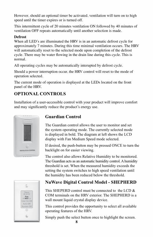
Guardian Control
The Guardian control allows the user to monitor and set the system operating mode. The currently selected mode is displayed in bold. The diagram at left shows the LCD display with Fan Medium Speed mode selected.
If desired, the push-button may be pressed ONCE to turn the backlight on for easier viewing.
The control also allows Relative Humidity to be monitored. The Guardian acts as an automatic humidity control. A humidity threshold is set. When the measured humidity exceeds the setting the system switches to high speed ventilation until the humidity has been reduced below the threshold.
NuWave Digital Control Model - SHEPHERD
This SHEPERD control must be connected to the LCD & COM terminals on the HRV exterior. The SHEPHERD is a wall mount liquid crystal display device.
This control provides the opportunity to select all available operating features of the HRV.
Simply push the select button once to highlight the screen.
However, should an optional timer be activated, ventilation will turn on to high speed until the timer expires or is turned off.This intermittent cycle of 20 minutes ventilation ON followed by 40 minutes of ventilation OFF repeats automatically until another selection is made.Defrost When all LED’s are illuminated the HRV is in an automatic defrost cycle for approximately 7 minutes. During this time minimal ventilation occurs. The HRV will automatically reset to the selected mode upon completion of the defrost cycle. There may be water flowing in the drain line during this cycle. This is normal.All operating cycles may be automatically interupted by defrost cycle.Should a power interruption occur, the HRV control will reset to the mode of operation selected.The current mode of operation is displayed at the LEDs located on the front panel of the HRV.
OPTIONAL CONTROLS
Installation of a user-accessible control with your product will improve comfort and may significantly reduce the product’s energy use.
9
Continue to press the select button until the desired fearture is highlighted.
The HRV will then assume the selected mode of operation.
Install using 18/2 thermostat wire or telephone wire up to two may be installed per HRV. No electrical box is required.Refer to wiring diagram in this manual.
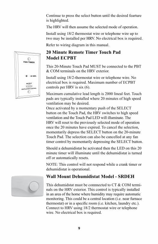
20 Minute Remote Timer Touch Pad Model ECPBT
This 20-Minute Touch Pad MUST be connected to the PBT & COM terminals on the HRV exterior.
Install using 18/2-thermostat wire or telephone wire. No electrical box is required. Maximum number of ECPBT controls per HRV is six (6).
Maximum cumulative lead length is 2000 lineal feet. Touch pads are typically installed where 20 minutes of high speed ventilation may be desired. Once activated by a momentary push of the SELECT button on the Touch Pad, the HRV switches to high speed ventilation and the Touch Pad LED will illuminate. The HRV will reset to the previously selected mode of operation once the 20 minutes have expired. To cancel the selection, momentarily depress the SELECT button on the 20-minute Touch Pad. The selection can also be cancelled at any fan timer control by momentarily depressing the SELECT button.
Should a dehumidistat be activated then the LED on this 20 minute timer will illuminate until the dehumidistat is turned off or automatically resets.
NOTE: This control will not respond while a crank timer or dehumidistat is operational.
Wall Mount Dehumidistat Model - SRDEH
This dehumidstat must be connnected to CT & COM termi-nals on the HRV exterior. This control is typically installed in an area of the home where humidity may require automatic monitoring. This could be a central location (i.e. near furnace thermostat) or in a specific room (i.e. kitchen, laundry etc.). Connect to HRV using 18/2 thermostat wire or telephone wire. No electrical box is required.
10
Installation Options
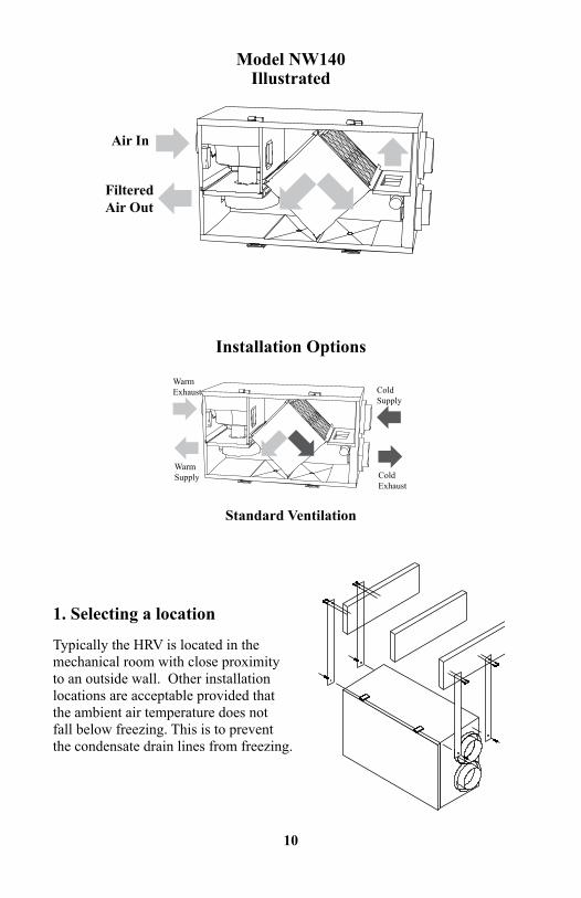
1. Selecting a location
Typically the HRV is located in the mechanical room with close proximity to an outside wall. Other installation locations are acceptable provided that the ambient air temperature does not fall below freezing. This is to prevent the condensate drain lines from freezing.
Standard Ventilation
Air In
Filtered Air Out
WarmExhaust
WarmSupply
ColdSupply
ColdExhaust
Model NW140Illustrated
11
2. Mounting the HRV
Included with the HRV are four (4) laminated rubber hanging straps. These are to be secured at each of the four corners of the HRV using the screws provided. The other ends of the straps should be secured to the floor joists using large head screws. To ensure proper condensate flow, HRV must be installed level in both directions.
To ensure quiet operation of ENERGY STAR qualified HRV/ERV’s, each product should be installed using sound attenuation techniques appropriate for the installation.
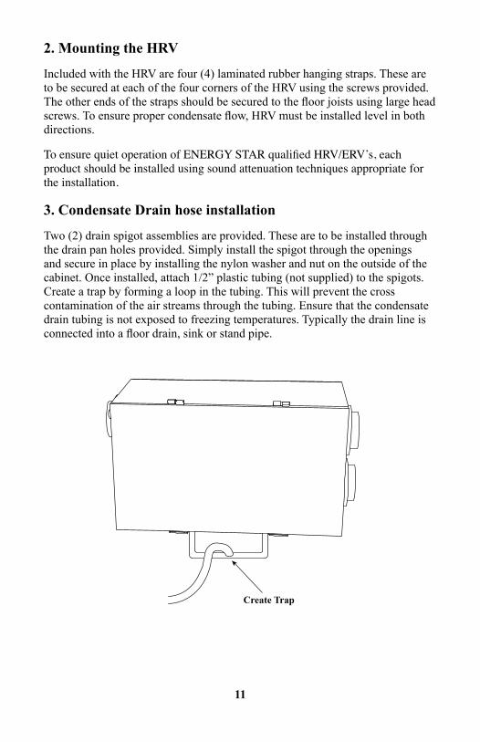
3. Condensate Drain hose installation
Two (2) drain spigot assemblies are provided. These are to be installed through the drain pan holes provided. Simply install the spigot through the openings and secure in place by installing the nylon washer and nut on the outside of the cabinet. Once installed, attach 1/2” plastic tubing (not supplied) to the spigots. Create a trap by forming a loop in the tubing. This will prevent the cross contamination of the air streams through the tubing. Ensure that the condensate drain tubing is not exposed to freezing temperatures. Typically the drain line is connected into a floor drain, sink or stand pipe.
Create Trap
12
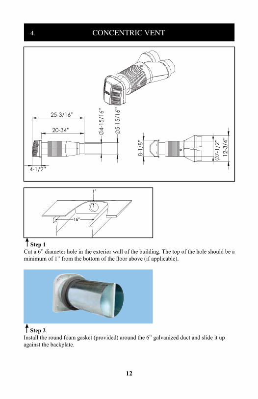
Step 1Cut a 6” diameter hole in the exterior wall of the building. The top of the hole should be a minimum of 1” from the bottom of the floor above (if applicable).
16”
1”
Step 2Install the round foam gasket (provided) around the 6” galvanized duct and slide it up against the backplate.
7-
1/2”
8-1
/8”
20-34”
25-3/16”
4-1/2”
4-
15/1
6”
5-
15/1
6”
12-
3/4”
4. CONCENTRIC VENT
13
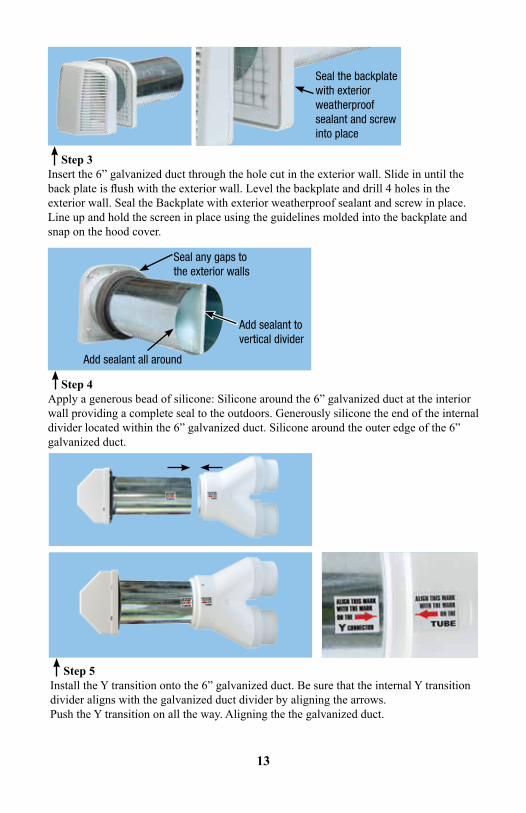
Step 3Insert the 6” galvanized duct through the hole cut in the exterior wall. Slide in until the back plate is flush with the exterior wall. Level the backplate and drill 4 holes in the exterior wall. Seal the Backplate with exterior weatherproof sealant and screw in place. Line up and hold the screen in place using the guidelines molded into the backplate and snap on the hood cover.
Seal the backplate with exterior weatherproof sealant and screw into place
Step 4Apply a generous bead of silicone: Silicone around the 6” galvanized duct at the interior wall providing a complete seal to the outdoors. Generously silicone the end of the internal divider located within the 6” galvanized duct. Silicone around the outer edge of the 6” galvanized duct.
Seal any gaps to the exterior walls
Add sealant to vertical divider
Add sealant all around
Step 5Install the Y transition onto the 6” galvanized duct. Be sure that the internal Y transition divider aligns with the galvanized duct divider by aligning the arrows.Push the Y transition on all the way. Aligning the the galvanized duct.
14
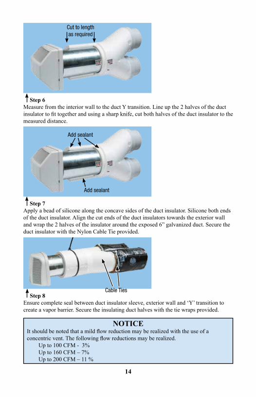
Step 6Measure from the interior wall to the duct Y transition. Line up the 2 halves of the duct insulator to fit together and using a sharp knife, cut both halves of the duct insulator to the measured distance.
Cut to lengthas required
Step 7Apply a bead of silicone along the concave sides of the duct insulator. Silicone both ends of the duct insulator. Align the cut ends of the duct insulators towards the exterior wall and wrap the 2 halves of the insulator around the exposed 6” galvanized duct. Secure the duct insulator with the Nylon Cable Tie provided.
Add sealant
Add sealant
Step 8Ensure complete seal between duct insulator sleeve, exterior wall and ‘Y’ transition to create a vapor barrier. Secure the insulating duct halves with the tie wraps provided.
Cable Ties
NOTICEIt should be noted that a mild flow reduction may be realized with the use of a concentric vent. The following flow reductions may be realized.
Up to 100 CFM - 3% Up to 160 CFM – 7% Up to 200 CFM – 11 %
15
installationClearances
• Minimuim 6’ (2m) away from dryer vents, furnace exhaust (medium or high efficiency furnaces), driveways, oil fill pipes, gas meters, or garbage containers• At least 18” (457 mm) above the ground, or above the depth of expected snow accumulation.•At least 3’ (1m) from the corner of the building.• Do not locate in a garage, attic or crawl space.
Included in this Kit- Hood Assembly - Foam Gasket- Y transition - Duct Insulator (2 pieces)- Nylon Cable Tie (3) - Screen- Four #8 x 1 1/2Wood Screws and rawl plugs
Additional Materials Required for this Kit- Waterproof sealant (silicone)
Weather hoods should be installed:
• Separate air intake and exhaust outlet openings, when located on the same wall or roof, shall be installed so as to avoid contamination of the ventilation air by the exhaust air.• Intake openings shall be located so as to avoid contamination of the ventilation air from other local sources such as automobile exhausts and exhaust from adjacent buildings.• The distance from the bottom of an air intake opening to finished ground level or to any nearer and lower permanent horizontal surface shall be not less than 450 mm or the depth of expected snow accumulation, whichever is greater.• The distance separating air intakes from building envelope penetrations that are potential sources of contaminants, such as gas vents or oil fill pipes, shall be not less than 900 mm.• Locate away from prevailing winds whenever possible.
Sealant must be applied as per instructions or leakage and condensation may occur.CAuTiON!
Insulate the Fresh Air Supply and Stale Air Exhaust ductwork back to the unit.ATTENTiON!
Contact your local building authority before installation of the Concentric Vent to verify compliance with local building codes.
ATTENTiON!
16
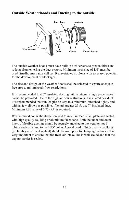
Outside Weatherhoods and Ducting to the outside.
The outside weather hoods must have built in bird screens to prevent birds and rodents from entering the duct system. Minimum mesh size of 1/4” must be used. Smaller mesh size will result in restricted air flows with increased potential for the development of blockages.
The size and design of the weather hoods shall be selected to ensure adequate free area to minimize air flow restrictions.
It is recommended that 6” insulated ducting with a integral single piece vapour barrier be provided. Due to the high air flow restrictions in insulated flex duct it is recommended that run lengths be kept to a minimum, stretched tightly and with as few elbows as possible, if length greater 25 ft. use 7” insulated duct. Minimum RSI value of 0.75 (R4) is required.
Weather hood collar should be screwed to inner surface of sill plate and sealed with high quality caulking or aluminum faced tape. Both the inner and outer liners of flexible ducting should be securely attached to the weather hood tubing and collar and to the HRV collar. A good bead of high quality caulking (preferably acoustical sealant) should be used prior to clamping the liners. It is very important to ensure that the fresh air intake line is well sealed and that the vapour barrier is sealed.
InsulationInner Liner
Collar Clamp Vapour BarrierWeatherhood
17
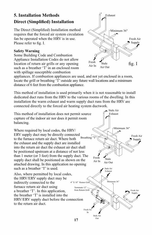
5. Installation MethodsDirect (Simplified) Installation
The Direct (Simplified) Installation method requires that the forced air system circulation fan be operated when the HRV is in use. Please refer to fig. I.
Safety Warning Some Building Code and Combustion Appliance Installation Codes do not allow location of return air grills or any opening such as a breather ‘T’ in an enclosed room with spillage susceptible combustion appliances. If combustion appliances are used, and not yet enclosed in a room, locate the grill or breathing ‘T’ outside any future wall locations and a minimum distance of 6 feet from the combustion appliance.
This method of installation is used primarily when it is not reasonable to install dedicated duct runs from the HRV to the various rooms of the dwelling. In this installation the warm exhaust and warm supply duct runs from the HRV are connected directly to the forced air heating system ductwork.
This method of installation does not permit source capture of the indoor air nor does it permit room balancing.
Where required by local codes, the HRV/ERV supply duct may be directly connected to the furnace return air duct. Where both the exhaust and the supply duct are installed into the return air duct the exhaust air duct shall be positioned upstream at a distance of not less than 1 meter (or 3 feet) from the supply duct. The supply duct shall be positioned as shown on the attached drawing. In this application no opening such as a breather ‘T’ is used. Also, where permitted by local codes, the HRV/ERV supply duct may be indirectly connected to the furnace return air duct using a breather ‘T’. In this application, the breather ‘T’ is installed into the HRV/ERV supply duct before the connection to the return air duct.
Stale AirExhaust
Fresh Air In
Fresh Air Supply
Minimum 36"
Stale Air Out
fig. I
Stale AirExhaust
Fresh Air In
Fresh Air Supply
Minimum 36"
Stale Air Out
Breathing "T"
Minimum 36”
Fresh AirSupply
Stale AirExhaust
Stale AirOut
Fresh AirIn
Terminate 12”from Return Grill
4” X 10” Return Grill
18
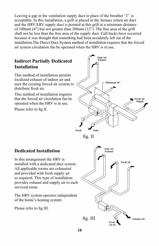
Indirect Partially Dedicated Installation
This method of installation permits localized exhaust of indoor air and uses the existing forced air system to distribute fresh air.This method of installation requires that the forced air circulation fan be operated when the HRV is in use.Please refer to fig II.
fig. II
Stale AirExhaust
Fresh Air In
Fresh Air Supply
Minimum 36"
Stale Air Out
Dedicated Installation
In this arrangement the HRV is installed with a dedicated duct system. All applicable rooms are exhausted and provided with fresh supply air as required. This type of installation provides exhaust and supply air to each serviced room.
The HRV system operates independent of the home’s heating system.
Please refer to fig III.
fig. IIIFresh Air In
Fresh Air
Exhaust Air
Stale AirExhaust
Leaving a gap in the ventilation supply duct in place of the breather ‘T’ is acceptable. In this installation, a grill is placed in the furnace return air duct and the HRV/ERV supply duct is pointed at this grill at a minimum distance of 100mm (4”) but not greater than 300mm (12”). The free area of the grill shall not be less than the free area of the supply duct. Call backs have occurred because it was thought that something had been accidently left out of the installation.The Direct Duct System method of installation requires that the forced air system circulation fan be operated when the HRV is in use.
19
6. Interior Ducting
Ducting to the central forced air ductwork system, or if used, a dedicated duct system, should be made of galvanized metal whenever possible.
To minimize airflow losses, runs should be kept as short as possible using 45 degree elbows instead of 90 degree. Whenever possible use “Y” fittings instead of “T” fittings.
All joints must be fastened with screws, rivets or duct sealant and wrapped with a quality duct tape to prevent leakage. If standard grills are used, it is recommended that wall grills of not less than 6” x 12” and floor grills of no less than 4” x 10” be used to minimize air flow restrictions.
7. Fresh Air Supply Ducting
Fresh air supply ducting to the living space may be either a dedicated or an indirect duct system. Please refer to figures II and II.
Should the indirect method be used it is suggested that at the point of connection to the HRV that a short length of flex duct be used to electrically isolate the two systems.
Fresh air supply grills may be either wall or ceiling mounted. Avoid locating these grills where room occupants may be exposed to the fresh air supply as this air temperature may be slightly less than the room air temperature.
Also, it is recommended that adjustable grills such as round “Tech Grills” be used to permit balancing of the ventilation by room application.
20
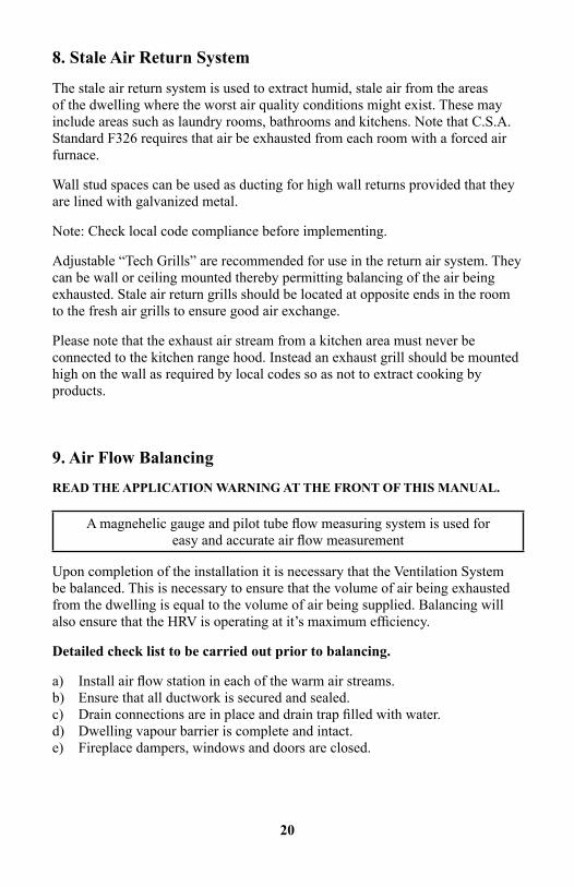
8. Stale Air Return System
The stale air return system is used to extract humid, stale air from the areas of the dwelling where the worst air quality conditions might exist. These may include areas such as laundry rooms, bathrooms and kitchens. Note that C.S.A. Standard F326 requires that air be exhausted from each room with a forced air furnace.
Wall stud spaces can be used as ducting for high wall returns provided that they are lined with galvanized metal.
Note: Check local code compliance before implementing.
Adjustable “Tech Grills” are recommended for use in the return air system. They can be wall or ceiling mounted thereby permitting balancing of the air being exhausted. Stale air return grills should be located at opposite ends in the room to the fresh air grills to ensure good air exchange.
Please note that the exhaust air stream from a kitchen area must never be connected to the kitchen range hood. Instead an exhaust grill should be mounted high on the wall as required by local codes so as not to extract cooking by products.
9. Air Flow BalancingREAD THE APPLICATION WARNING AT THE FRONT OF THIS MANUAL.
A magnehelic gauge and pilot tube flow measuring system is used for easy and accurate air flow measurement
Upon completion of the installation it is necessary that the Ventilation System be balanced. This is necessary to ensure that the volume of air being exhausted from the dwelling is equal to the volume of air being supplied. Balancing will also ensure that the HRV is operating at it’s maximum efficiency.
Detailed check list to be carried out prior to balancing.
a) Install air flow station in each of the warm air streams. b) Ensure that all ductwork is secured and sealed. c) Drain connections are in place and drain trap filled with water. d) Dwelling vapour barrier is complete and intact. e) Fireplace dampers, windows and doors are closed.
21
f) Clothes dryer off, (if vented to the outdoors) g) Furnace, hot water heater, (non direct vent) are turned off. h) All other exhaust fans are off. i) Ensure that HRV filters and core are in place and integral balancing dampers are wide open. j) Power up HRV and set to high speed. k) Adjust all branch tech grills and registers to desired air flows. l) After taking readings at both the stale air being exhausted and the fresh air supply air stream, damper down the higher air flow stream with the integral balancing damper to equal the lower volume air stream. m) Once the air flows are balanced lock the balancing dampers in place. n) While it is necessary to ensure that both air streams are balanced within 10% of each other, a near balanced condition should be possible. o) Upon completion, return the fan speed selection to the normal speed of low.
A positive pressure situation within the dwelling may drive moist air into the external walls of the dwelling where, in cold weather, it may condensate, potentially causing structural damage.
A negative pressure within the dwelling may have severe undesirable effects. In some geographic locations, radon gas may be drawn into the living space. A negative condition may also cause back drafting of vented combustion appliances such as fireplaces and furnaces.
When it is possible for excessive pressurization or depressurization of a dwelling to occur it may be necessary to perform a House Pressure Test. This test is most important where fuel fired devices are installed that are susceptible to spillage.
IT IS YOUR RESPONSIBILITY TO DETERMINE IF THE “HOUSE PRESSURE TEST” IS REQUIRED.
22
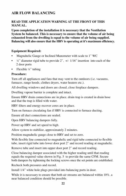
AiR FLOW BALANCiNg
READ THE AppLiCATiON WARNiNg AT THE FRONT OF THis MANuAL.upon completion of the installation it is necessary that the Ventilation system be balanced. This is necessary to ensure that the volume of air being exhausted from the dwelling is equal to the volume of air being supplied. Balancing will also ensure that the HRV is operating at it’s maximum efficiency.
Equipment Required:• Magnahelic Gauge or Inclined Manometer with scale to 1” WC• ¼” diameter rigid tube to provide 2”, +/- 1/16” insertion into each of the 2 door ports• Flexible ¼” tubingprocedure:Turn off all appliances and fans that may vent to the outdoors (i.e. vacuums, furnaces, range hoods, clothes dryers, water heaters etc.).All dwelling windows and doors are closed, close fireplace dampers.Dwelling vapour barrier is complete and intact.Ensure HRV drain connections are in place, drain trap is created in drain hose and that the trap is filled with water.HRV filters and energy recover cores are in place.Turn on furnace circulating fan if HRV is connected to furnace ducting.Ensure all duct connections are sealed.Open HRV balancing dampers fully.Power up HRV and set speed to high.Allow system to stabilize, approximately 2 minutes.Position magnahelic gauge close to HRV and set to zero.With flexible line connected to magnahelic and rigid tube connected to flexible tube, insert rigid tube into lower door port 2” and record reading at magnahelic.Remove tube and insert into upper door port 2” and record reading.Close balancing damper associated with the higher reading until that reading equals the required value shown in Fig. 5 to provide the same CFM. Secure both dampers by tightening the locking screws once the set points are established.Recheck both pressures and record.Install 1/4” white hole plugs provided into balancing ports in door.While it is necessary to ensure that both air streams are balanced within 10%, a near balanced condition should be possible.
23
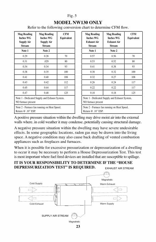
Fig. 5
MODEL NW130 ONLY Refer to the following conversion chart to determine CFM flow.
A positive pressure situation within the dwelling may drive moist air into the external walls where, in cold weather it may condense, potentially causing structural damage.A negative pressure situation within the dwelling may have severe undesirable effects. In some geographic locations, radon gas may be drawn into the living space. A negative condition may also cause back drafting of vented combustion appliances such as fireplaces and furnaces.When it is possible for excessive pressurization or depressurization of a dwelling to occur it may be necessary to perform a House Depressurization Test. This test is most important where fuel fired devices are installed that are susceptible to spillage.iT is YOuR REspONsiBiLiTY TO DETERMiNE iF THE “HOusE DEpREssuRiZATiON TEsT” is REQuiRED.
Mag Readinginches Wgsupply Air
stream
Mag Readinginches Wgsupply Air
stream
CFMEquivalent
Note 1 Note 2
0.29 0.28 70
0.31 .029 80
0.34 0.34 93
0.38 0.35 100
0.41 0.40 108
0.43 0.42 112
0.45 0.44 117
0.47 0.48 125
Note 1 - Dedicated Supply and Exhaust System, NO furnace present
Note 2 - Furnace fan running on Heat Speed, Return @ .10” ESP.
Mag Readinginches WgExhaust Air
stream
Mag Readinginches WgExhaust Air
stream
CFMEquivalent
Note 1 Note 2
0.57 0.56 70
0.53 0.52 80
0.41 0.38 93
0.38 0.32 100
0.32 0.27 108
0.26 0.24 117
0.22 0.22 117
0.18 0.18 125
Note 1 - Dedicated Supply and Exhaust System, NO furnace present
Note 2 - Furnace fan running on Heat Speed, Return @ .10” ESP.
Cold Supply
Cold Exhaust
Warm Exhaust
Magnahelic
Magnahelic
Warm Supply
EXHAUST AIR STREAM
SUPPLY AIR STREAM
24
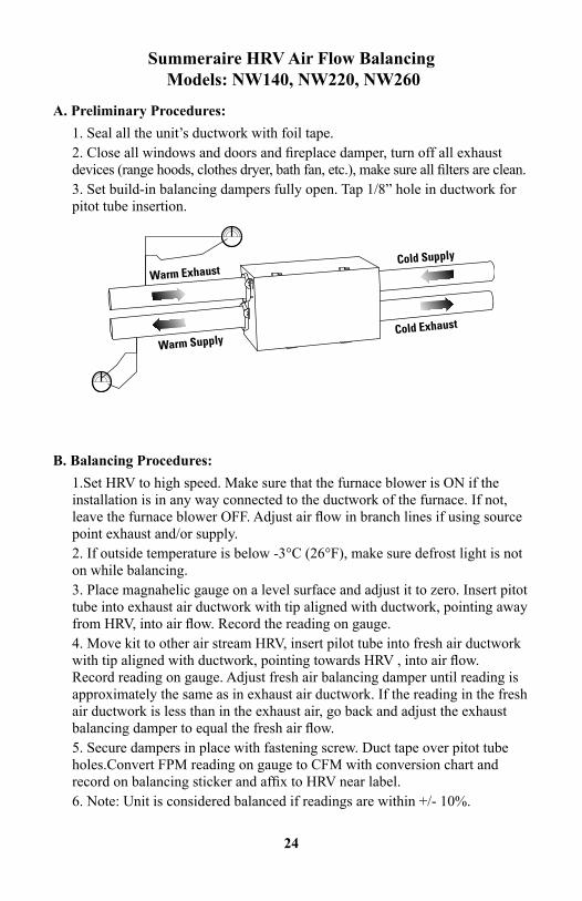
Summeraire HRV Air Flow Balancing Models: NW140, NW220, NW260
A. Preliminary Procedures: 1. Seal all the unit’s ductwork with foil tape.2. Close all windows and doors and fireplace damper, turn off all exhaust devices (range hoods, clothes dryer, bath fan, etc.), make sure all filters are clean.3. Set build-in balancing dampers fully open. Tap 1/8” hole in ductwork for pitot tube insertion.
B. Balancing Procedures:1.Set HRV to high speed. Make sure that the furnace blower is ON if the installation is in any way connected to the ductwork of the furnace. If not, leave the furnace blower OFF. Adjust air flow in branch lines if using source point exhaust and/or supply.2. If outside temperature is below -3°C (26°F), make sure defrost light is not on while balancing.3. Place magnahelic gauge on a level surface and adjust it to zero. Insert pitot tube into exhaust air ductwork with tip aligned with ductwork, pointing away from HRV, into air flow. Record the reading on gauge.4. Move kit to other air stream HRV, insert pilot tube into fresh air ductwork with tip aligned with ductwork, pointing towards HRV , into air flow. Record reading on gauge. Adjust fresh air balancing damper until reading is approximately the same as in exhaust air ductwork. If the reading in the fresh air ductwork is less than in the exhaust air, go back and adjust the exhaust balancing damper to equal the fresh air flow.5. Secure dampers in place with fastening screw. Duct tape over pitot tube holes.Convert FPM reading on gauge to CFM with conversion chart and record on balancing sticker and affix to HRV near label.6. Note: Unit is considered balanced if readings are within +/- 10%.
25
HR
V T
RO
UB
LE
SH
OO
TIN
G G
UID
EO
PER
ATIO
N G
UID
E
PRO
BL
EM
PRO
BA
BL
E C
AU
SESO
LU
TIO
N
PER
SIST
ENT
CO
ND
ENSA
TIO
N
ON
WIN
DO
WS
IMPR
OPE
R A
DJU
STM
ENT
OF
DEH
UM
IDIS
TAT(
S).
AD
JUST
DEH
UM
IDIS
TAT(
S) T
O C
OR
REC
T R
H R
EAD
ING
(see
op
erat
ion
man
ual),
AD
JUST
TO
A L
OW
ER S
ETTI
NG
. C
HEC
K O
PER
ATIO
N O
F D
EHU
MID
ISTA
T, IF
DEF
ECTI
VE,
REP
LAC
E.
INST
ALL
A D
EHU
MID
ISTA
T IN
LIV
ING
AR
EA O
F H
OM
E.
IMPR
OPE
R V
ENTI
LATI
ON
RAT
E.EN
SUR
E H
RV IS
ON
CO
NTI
NU
OU
SLY.
IN
CR
EASE
FA
N S
PEED
. B
ALA
NC
E SY
STEM
.
DEF
RO
ST N
OT
WO
RK
ING
.B
RO
KEN
DA
MPE
R B
LAD
E A
SSY.
REP
LAC
E.
FRES
H A
IR D
UC
T FR
OZE
N
OR
VER
Y C
OLD
(DEF
RO
ST L
IGH
T C
OM
ES O
N) .
FAIL
ED M
AIN
CO
NTR
OL
BO
AR
D.
IF D
AM
PER
DO
OR
DO
ES N
OT
OPE
RAT
E D
UR
ING
“ST
ART
UP
SELF
DIA
GN
OST
IC”
BU
T PO
WER
LIG
HTS
AR
E O
N, B
OA
RD
MAY
R
EQU
IRE
REP
LAC
EMEN
T.
DEF
ECTI
VE
DA
MPE
R M
OTO
R.
REP
LAC
E.
INSP
ECT
CO
NN
ECTI
ON
BET
WEE
N M
OTO
R S
HA
FT A
ND
DA
MPE
R,
CO
UPL
ING
MAY
BE
LOO
SE.
HU
MID
ITY
LEV
EL T
OO
LO
WH
RV A
IR F
LOW
S IM
PRO
PER
LY B
ALA
NC
ED.
BA
LAN
CE
HRV
DEH
UM
IDIS
TAT
CO
NTR
OL
SET
TO
LO
W.
SET
DEH
UM
IDIS
TAT
TO A
HIG
HER
SET
PO
INT.
LIFE
STY
LE O
F O
CC
UPA
NTS
.H
UM
IDIT
Y M
AY H
AVE
TO B
E A
RTIF
ICIA
LLY
AD
DED
, i.e
. HU
MID
IFIE
R.
VEN
TILA
TIO
N R
ATE
TOO
HIG
HA
DJU
ST T
O L
OW
ER F
AN
SPE
ED O
R IN
TER
MIT
TEN
T
26
PRO
BL
EM
PRO
BA
BL
E C
AU
SESO
LU
TIO
N
HU
MID
ITY
LEV
EL T
OO
HIG
HH
RV A
IR F
LOW
S IM
PRO
PER
LY B
ALA
NC
EDB
ALA
NC
E H
RV
HRV
UN
DER
SIZE
D.
DEH
UM
IDIS
TAT
SET
TOO
HIG
HSE
T D
EHU
MID
ISTA
T TO
A L
OW
ER S
ETTI
NG
.
HRV
UN
DER
SIZE
D T
O H
AN
DLE
HO
T TU
B,
IND
OO
R P
OO
LS, E
TC.
CO
VER
PO
OLS
, HO
T TU
BS
ETC
. WH
EN N
OT
IN U
SE.
LIFE
STY
LES
OF
OC
CU
PAN
TSAV
OID
HA
NG
ING
CLO
THES
TO
DRY
INSI
DE,
AVO
ID S
TOR
ING
WO
OD
INSI
DE
AN
D V
ENT
DRY
ERS
OU
TSID
E.
HRV
AN
D/O
R D
UC
TS F
RO
STIN
G U
PH
RV A
IR F
LOW
S IM
PRO
PER
LY B
ALA
NC
EDB
ALA
NC
E H
RVN
OTE
: FR
OST
BU
ILD
UP
IS E
XPE
CTE
D O
N C
OR
ES P
RIO
RTO
INIT
IATI
NG
A D
EFR
OST
CY
CLE
.
SUPP
LY A
IR F
EELS
CO
OL
HRV
AIR
FLO
WS
IMPR
OPE
RLY
BA
LAN
CED
.B
ALA
NC
E H
RV.
POO
R L
OC
ATIO
N O
F SU
PPLY
GR
ILLS
.LO
CAT
E G
RIL
LS H
IGH
ON
WA
LLS
OR
UN
DER
BA
SEB
OA
RD
S.
OU
TDO
OR
TEM
PER
ATU
RE
EX
TREM
ELY
CO
LD.
IF S
UPP
LY A
IR IS
INST
ALL
ED IN
TO R
ETU
RN
AIR
OF
FUR
NA
CE,
FUR
NA
CE
FAN
NEE
DS
TO R
UN
CO
NST
AN
TLY
TO
DIS
TRIB
UTE
VEN
TILA
TIO
N A
IR C
OM
FORT
AB
LY.
ENSU
RE
THAT
A B
REA
THER
“T”
IS IN
STA
LLED
IN S
UPP
LY D
UC
T.PR
EHEA
TER
MAY
BE
REQ
UIR
ED.
WAT
ER IN
BO
TTO
M O
F H
RVD
RA
IN P
AN
(S) P
LUG
GED
EN
SUR
E “O
” R
ING
S O
N D
RA
IN S
PIG
OT
SEAT
S PR
OPE
RLY
LOO
K F
OR
KIN
KS
IN L
INE.
DR
AIN
LIN
ES O
BST
RU
CTE
DC
HEC
K W
ATER
DR
AIN
CO
NN
ECTI
ON
S.M
AK
E SU
RE
WAT
ER D
RA
INS
PRO
PER
LY F
RO
M T
HE
PAN
(S)
HRV
HEA
T EX
CH
AN
GE
CO
RE
NO
T IN
STA
LLED
PR
OPE
RLY
CH
ECK
OR
IEN
TATI
ON
LA
BEL
ON
FR
ON
T O
F C
OR
E A
ND
PO
SITI
ON
CO
RE
CO
RR
ECTL
Y.H
RV M
AY N
OT
BE
LEV
EL
27
PRO
BL
EM
PRO
BA
BL
E C
AU
SESO
LU
TIO
N
HU
MID
ITY
LEV
EL T
OO
HIG
HH
RV A
IR F
LOW
S IM
PRO
PER
LY B
ALA
NC
EDB
ALA
NC
E H
RV
HRV
UN
DER
SIZE
D.
DEH
UM
IDIS
TAT
SET
TOO
HIG
HSE
T D
EHU
MID
ISTA
T TO
A L
OW
ER S
ETTI
NG
.
HRV
UN
DER
SIZE
D T
O H
AN
DLE
HO
T TU
B,
IND
OO
R P
OO
LS, E
TC.
CO
VER
PO
OLS
, HO
T TU
BS
ETC
. WH
EN N
OT
IN U
SE.
LIFE
STY
LES
OF
OC
CU
PAN
TSAV
OID
HA
NG
ING
CLO
THES
TO
DRY
INSI
DE,
AVO
ID S
TOR
ING
WO
OD
INSI
DE
AN
D V
ENT
DRY
ERS
OU
TSID
E.
HRV
AN
D/O
R D
UC
TS F
RO
STIN
G U
PH
RV A
IR F
LOW
S IM
PRO
PER
LY B
ALA
NC
EDB
ALA
NC
E H
RVN
OTE
: FR
OST
BU
ILD
UP
IS E
XPE
CTE
D O
N C
OR
ES P
RIO
RTO
INIT
IATI
NG
A D
EFR
OST
CY
CLE
.
SUPP
LY A
IR F
EELS
CO
OL
HRV
AIR
FLO
WS
IMPR
OPE
RLY
BA
LAN
CED
.B
ALA
NC
E H
RV.
POO
R L
OC
ATIO
N O
F SU
PPLY
GR
ILLS
.LO
CAT
E G
RIL
LS H
IGH
ON
WA
LLS
OR
UN
DER
BA
SEB
OA
RD
S.
OU
TDO
OR
TEM
PER
ATU
RE
EX
TREM
ELY
CO
LD.
IF S
UPP
LY A
IR IS
INST
ALL
ED IN
TO R
ETU
RN
AIR
OF
FUR
NA
CE,
FUR
NA
CE
FAN
NEE
DS
TO R
UN
CO
NST
AN
TLY
TO
DIS
TRIB
UTE
VEN
TILA
TIO
N A
IR C
OM
FORT
AB
LY.
ENSU
RE
THAT
A B
REA
THER
“T”
IS IN
STA
LLED
IN S
UPP
LY D
UC
T.PR
EHEA
TER
MAY
BE
REQ
UIR
ED.
WAT
ER IN
BO
TTO
M O
F H
RVD
RA
IN P
AN
(S) P
LUG
GED
EN
SUR
E “O
” R
ING
S O
N D
RA
IN S
PIG
OT
SEAT
S PR
OPE
RLY
LOO
K F
OR
KIN
KS
IN L
INE.
DR
AIN
LIN
ES O
BST
RU
CTE
DC
HEC
K W
ATER
DR
AIN
CO
NN
ECTI
ON
S.M
AK
E SU
RE
WAT
ER D
RA
INS
PRO
PER
LY F
RO
M T
HE
PAN
(S)
HRV
HEA
T EX
CH
AN
GE
CO
RE
NO
T IN
STA
LLED
PR
OPE
RLY
CH
ECK
OR
IEN
TATI
ON
LA
BEL
ON
FR
ON
T O
F C
OR
E A
ND
PO
SITI
ON
CO
RE
CO
RR
ECTL
Y.H
RV M
AY N
OT
BE
LEV
EL
PRO
BL
EM
PRO
BA
BL
E C
AU
SESO
LU
TIO
N
AIR
FLO
WS
AR
E PO
OR
HRV
AIR
FLO
W IM
PRO
PER
LY B
ALA
NC
EDB
ALA
NC
E H
RV.
FILT
ER/C
OR
E PL
UG
GED
UP
CLE
AN
AN
D R
EIN
STA
LL
1/4”
MES
H O
N O
UTS
IDE
HO
OD
S PL
UG
GED
REM
OV
E O
BST
RU
CTI
ON
S IN
DU
CT(
S), H
OO
DS
AN
D G
RIL
LS.
IMPR
OPE
RLY
SIZ
ED D
UC
TIN
G
UN
DER
SIZ
ED H
RVM
ALF
UN
CTI
ON
WIT
H H
RVIN
SPEC
T FA
N W
HEE
LS T
O E
NSU
RE
THEY
AR
E TU
RN
ING
FR
EELY
CO
ND
ENSA
TIO
N O
R IC
E B
UIL
D
UP
IN IN
SULA
TED
DU
CT
INC
OM
PLET
E VA
POU
R B
AR
RIE
R A
RO
UN
D
INSU
LATE
D D
UC
TTA
PE A
LL JO
INTS
ENSU
RE
THAT
VA
POU
R B
AR
RIE
R IS
CO
MPL
ETEL
Y S
EALE
D
UN
USU
ALL
Y H
UM
ID A
MB
IEN
TW
RO
NG
APP
LIC
ATIO
N O
F H
RV
DO
OR
GA
SKET
DA
MA
GED
REP
LAC
E G
ASK
ETIN
G
WAT
ER L
EAK
SH
RV N
OT
LEV
ELLE
VEL
HRV
EXC
ESSI
VE
WAT
ER D
UE
TO N
EW
WET
CO
NST
RU
CTI
ON
OPE
RAT
E H
RV O
N L
OW
ER S
PEED
ie. I
NTE
RM
ITTE
NT
FRO
ST O
N F
RES
H A
IR IN
TAK
E
& S
TALE
AIR
EX
HA
UST
FLE
XH
RV C
OR
E IN
STA
LLED
IN R
EVER
SEIN
STA
LL C
OR
E C
OR
REC
TLY
“FR
ON
T” O
F C
OR
E H
AS
INST
ALL
ATIO
N IN
STR
UC
TIO
N L
AB
ELIN
STA
LL W
ITH
LA
BEL
FA
CIN
G H
RV D
OO
R
VAPO
UR
BA
RR
IER
INC
OM
PLET
ER
EPA
IR S
EAL
OF
ALL
CR
AC
KS
AN
D T
EAR
S
HRV
STA
TUS
PAN
EL F
LASH
ING
HIG
H C
ON
TIN
UO
USL
YH
RV IN
TER
NA
L D
EHU
MID
ISTA
T SE
T TO
LO
WA
DJU
ST D
EHU
MID
ISTA
T TO
HIG
HER
SET
PO
INT
28
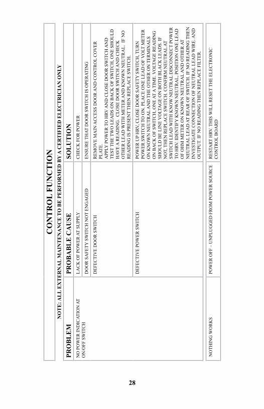
CO
NT
RO
L FU
NC
TIO
N
NO
TE
: AL
L E
XT
ER
NA
L M
AIN
TE
NA
NC
E T
O B
E P
ER
FOR
ME
D B
Y A
CE
RT
IFIE
D E
LE
CT
RIC
IAN
ON
LY
PRO
BL
EM
PRO
BA
BL
E C
AU
SESO
LU
TIO
N
NO
PO
WER
IND
ICAT
ION
AT
ON
/OFF
SW
ITC
HLA
CK
OF
POW
ER A
T SU
PPLY
CH
ECK
FO
R P
OW
ER
DO
OR
SA
FETY
SW
ITC
H N
OT
ENG
AG
EDEN
SUR
E TH
AT D
OO
R S
WIT
CH
IS O
PER
ATIN
G
DEF
ECTI
VE
DO
OR
SW
ITC
HR
EMO
VE
MA
IN A
CC
ESS
DO
OR
AN
D C
ON
TRO
L C
OV
ER
PLAT
E.A
PPLY
PO
WER
TO
HRV
AN
D C
LOSE
DO
OR
SW
ITC
H A
ND
TE
ST T
HE
TWO
LEA
DS
ON
BA
CK
OF
SWIT
CH
, ON
E SH
OU
LD
HAV
E A
REA
DIN
G.
CLO
SE D
OO
R S
WIT
CH
AN
D C
HEC
K
OTH
ER L
EAD
WIT
H M
ETER
AN
D K
NO
WN
NEU
TRA
L. I
F N
O
REA
DIN
G IS
PR
ESEN
T TH
EN R
EPLA
CE
SWIT
CH
.
DEF
ECTI
VE
POW
ER S
WIT
CH
POW
ER U
P H
RV, C
LOSE
DO
OR
SA
FETY
SW
ITC
H, T
UR
N
POW
ER S
WIT
CH
TO
ON
. PLA
CE
ON
E LE
AD
OF
VO
LT M
ETER
O
N K
NO
WN
NEU
TRA
L A
ND
TH
E O
THER
ON
TER
MIN
ALS
O
N B
AC
K O
F SW
ITC
H, O
NE
AT A
TIM
E. V
OLT
AG
E R
EAD
ING
SH
OU
LD B
E LI
NE
VO
LTA
GE
ON
BO
TH B
LAC
K L
EAD
S. IF
N
OT,
TH
EN R
EPLA
CE
SWIT
CH
. CO
NFI
RM
NEU
TRA
L AT
SW
ITC
H L
EAD
WIT
H K
NO
W N
EUTR
AL
DIS
CO
NN
ECT
POW
ER
TO H
RV. I
DEN
TIFY
KN
OW
N N
EUTR
AL,
PO
SITI
ON
ON
E LE
AD
O
F O
HM
MET
ER O
N K
NO
WN
NEU
TRA
L A
ND
OTH
ER A
T N
EUTR
AL
LEA
D A
T R
EAR
OF
SWIT
CH
. IF
NO
REA
DIN
G T
HEN
IN
VES
TIG
ATE
CO
NN
ECTI
ON
OF
NEU
TRA
L LE
AD
WIR
E. A
ND
O
UTP
UT.
IF N
O R
EAD
ING
TH
EN R
EPLA
CE
FILT
ER.
NO
THIN
G W
OR
KS
POW
ER O
FF –
UN
PLU
GG
ED F
ROM
PO
WER
SO
URC
ER
ESTA
RT H
RV. T
HIS
WIL
L R
ESET
TH
E EL
ECTR
ON
IC
CO
NTR
OL
BO
AR
D
29
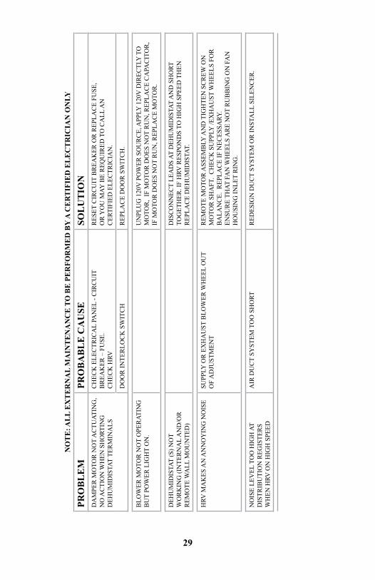
NO
TE
: AL
L E
XT
ER
NA
L M
AIN
TE
NA
NC
E T
O B
E P
ER
FOR
ME
D B
Y A
CE
RT
IFIE
D E
LE
CT
RIC
IAN
ON
LY
PRO
BL
EM
PRO
BA
BL
E C
AU
SESO
LU
TIO
N
DA
MPE
R M
OTO
R N
OT
AC
TUAT
ING
, N
O A
CTI
ON
WH
EN S
HO
RTIN
G
DEH
UM
IDIS
TAT
TER
MIN
ALS
CH
ECK
ELE
CTR
ICA
L PA
NEL
- C
IRC
UIT
B
REA
KER
– F
USE
. C
HEC
K H
RV
RES
ET C
IRC
UIT
BR
EAK
ER O
R R
EPLA
CE
FUSE
, O
R Y
OU
MAY
BE
REQ
UIR
ED T
O C
ALL
AN
C
ERTI
FIED
ELE
CTR
ICIA
N.
DO
OR
INTE
RLO
CK
SW
ITC
HR
EPLA
CE
DO
OR
SW
ITC
H.
BLO
WER
MO
TOR
NO
T O
PER
ATIN
GB
UT
POW
ER L
IGH
T O
N.
UN
PLU
G 1
20V
PO
WER
SO
UR
CE,
APP
LY 1
20V
DIR
ECTL
Y T
O
MO
TOR
, IF
MO
TOR
DO
ES N
OT
RU
N, R
EPLA
CE
CA
PAC
ITO
R,
IF M
OTO
R D
OES
NO
T R
UN
, REP
LAC
E M
OTO
R.
DEH
UM
IDIS
TAT
(S) N
OT
WO
RK
ING
(IN
TER
NA
L A
ND
/OR
R
EMO
TE W
ALL
MO
UN
TED
)
DIS
CO
NN
ECT
LEA
DS
AT D
EHU
MID
ISTA
T A
ND
SH
ORT
TO
GET
HER
. IF
HRV
RES
PON
DS
TO H
IGH
SPE
ED T
HEN
R
EPLA
CE
DEH
UM
IDIS
TAT.
HRV
MA
KES
AN
AN
NO
YIN
G N
OIS
ESU
PPLY
OR
EX
HA
UST
BLO
WER
WH
EEL
OU
T
OF
AD
JUST
MEN
TR
EMO
TE M
OTO
R A
SSEM
BLY
AN
D T
IGH
TEN
SC
REW
ON
M
OTO
R S
HA
FT.
CH
ECK
SU
PPLY
/EX
HA
UST
WH
EELS
FO
R
BA
LAN
CE.
REP
LAC
E IF
NEC
ESSA
RY.
ENSU
RE
THAT
FA
N W
HEE
LS A
RE
NO
T R
UB
BIN
G O
N F
AN
H
OU
SIN
G IN
LET
RIN
G.
NO
ISE
LEV
EL T
OO
HIG
H A
TD
ISTR
IBU
TIO
N R
EGIS
TER
SW
HEN
HRV
ON
HIG
H S
PEED
AIR
DU
CT
SYST
EM T
OO
SH
ORT
RED
ESIG
N D
UC
T SY
STEM
OR
INST
ALL
SIL
ENC
ER.
30
NO
TE
: AL
L E
XT
ER
NA
L M
AIN
TE
NA
NC
E T
O B
E P
ER
FOR
ME
D B
Y A
CE
RT
IFIE
D E
LE
CT
RIC
IAN
ON
LY
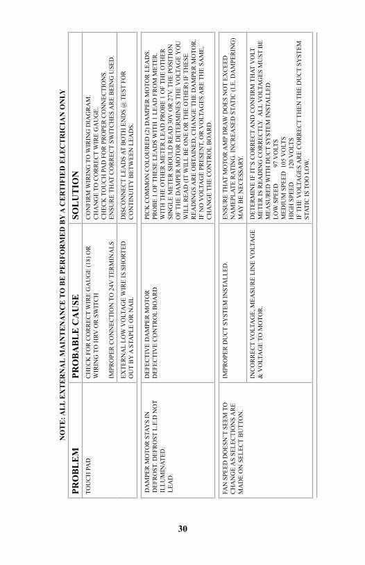
PRO
BL
EM
PRO
BA
BL
E C
AU
SESO
LU
TIO
N
TOU
CH
PA
DC
HEC
K F
OR
CO
RR
ECT
WIR
E G
AU
GE
(18)
OR
W
IRIN
G T
O H
RV O
R S
WIT
CH
IMPR
OPE
R C
ON
NEC
TIO
N T
O 2
4V T
ERM
INA
LS
CO
NFI
RM
WIR
ING
TO
WIR
ING
DIA
GR
AM
.C
HA
NG
E TO
CO
RR
ECT
WIR
E G
AU
GE.
CH
ECK
TO
UC
H P
AD
FO
R P
RO
PER
CO
NN
ECTI
ON
S.EN
SUR
E TH
AT C
OR
REC
T SW
ITC
HES
AR
E B
EIN
G U
SED
.
EXTE
RN
AL
LOW
VO
LTA
GE
WIR
E IS
SH
ORT
ED
OU
T B
Y A
STA
PLE
OR
NA
ILD
ISC
ON
NEC
T LE
AD
S AT
BO
TH E
ND
S @
TES
T FO
R
CO
NTI
NU
ITY
BET
WEE
N L
EAD
S.
DA
MPE
R M
OTO
R S
TAY
S IN
D
EFR
OST
. DEF
RO
ST L
.E.D
NO
T IL
LUM
INAT
ED.
LEA
D.
DEF
ECTI
VE
DA
MPE
R M
OTO
RD
EFEC
TIV
E C
ON
TRO
L B
OA
RD
PIC
K C
OM
MO
N C
OLO
UR
ED (2
) DA
MPE
R M
OTO
R L
EAD
S.
PRO
BE
1 O
F TH
ESE
LEA
DS
WIT
H 1
LEA
D F
RO
M M
ETER
. W
ITH
TH
E O
THER
MET
ER L
EAD
PR
OB
E 1
OF
THE
OTH
ER
SIN
GLE
MET
ER S
HO
ULD
REA
D 3
0V O
R 2
7V. T
HE
POSI
TIO
N
OF
THE
DA
MPE
R M
OTO
R D
ETER
MIN
ES T
HE
VO
LTA
GE
YO
U
WIL
L R
EAD
(IT
WIL
L B
E O
NE
OR
TH
E O
THER
) IF
THES
E R
EAD
ING
S A
RE
OB
TAIN
ED, C
HA
NG
E TH
E D
AM
PER
MO
TOR
. IF
NO
VO
LTA
GE
PRES
ENT,
OR
VO
LTA
GES
AR
E TH
E SA
ME,
C
HA
NG
E TH
E C
ON
TRO
L B
OA
RD
.
FAN
SPE
ED D
OES
N’T
SEE
M T
O
CH
AN
GE
AS
SELE
CTI
ON
S A
RE
MA
DE
ON
SEL
ECT
BU
TTO
N.
IMPR
OPE
R D
UC
T SY
STEM
INST
ALL
ED.
ENSU
RE
THAT
MO
TOR
AM
P D
RAW
DO
ES N
OT
EXC
EED
N
AM
EPLA
TE R
ATIN
G. I
NC
REA
SED
STA
TIC
(I.E
. DA
MPE
RIN
G)
MAY
BE
NEC
ESSA
RY.
INC
OR
REC
T V
OLT
AG
E, M
EASU
RE
LIN
E V
OLT
AG
E &
VO
LTA
GE
TO M
OTO
R.
DET
ERM
INE
IF IT
’S C
OR
REC
T A
ND
CO
NFI
RM
TH
AT V
OLT
M
ETER
IS R
EAD
ING
CO
RR
ECTL
Y. A
LL V
OLT
AG
ES M
UST
BE
MEA
SUR
ED W
ITH
DU
CT
SYST
EM IN
STA
LLED
.LO
W S
PEED
97
VO
LTS
MED
IUM
SPE
ED 1
05 V
OLT
SH
IGH
SPE
ED
12
0 V
OLT
SIF
TH
E V
OLT
AG
ES A
RE
CO
RR
ECT
THEN
TH
E D
UC
T SY
STEM
ST
ATIC
IS T
OO
LO
W.
31
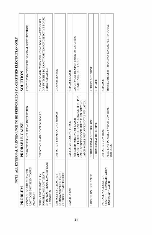
NO
TE
: AL
L E
XT
ER
NA
L M
AIN
TE
NA
NC
E T
O B
E P
ER
FOR
ME
D B
Y A
CE
RT
IFIE
D E
LE
CT
RIC
IAN
ON
LY
PRO
BL
EM
PRO
BA
BL
E C
AU
SESO
LU
TIO
N
CO
NTR
OL
BO
AR
D C
HA
NG
EDU
NIT
DO
ES N
OT
SEEM
TO
RU
NPR
OPE
RTY
DIP
SW
ITC
HES
NO
T SE
T A
S IN
STR
UC
TED
RES
ET D
IP S
WIT
CH
ES T
O O
RIG
INA
L SP
ECIF
ICAT
ION
S.
WH
EN U
NIT
IS IN
ITIA
LLY
PO
WER
ED O
N, U
NIT
STA
YS
IN D
EFR
OST
MO
DE
LON
GER
TH
AN
10
MIN
UTE
S
DEF
ECTI
VE
MA
IN C
ON
TRO
L B
OA
RD
CH
AN
GE
BO
AR
D. W
HEN
CH
AN
GIN
G B
OA
RD
ALW
AYS
SET
DIP
SW
ITC
HES
TO
EX
AC
T PO
SITI
ON
OF
DEF
ECTI
VE
BO
AR
D
BEI
NG
REP
LAC
ED.
DEF
RO
ST C
YC
LE A
CTI
VE
DU
RIN
G A
BO
VE
FREE
ZIN
GO
UTD
OO
R T
EMPE
RAT
UR
E
DEF
ECTI
VE
TEM
PER
ATU
RE
SEN
SOR
CH
AN
GE
SEN
SOR
LATC
H O
PEN
SEX
CES
SIV
E C
LOSI
NG
FO
RC
ER
EPLA
CE
LATC
H
REP
EATE
D F
OR
CIN
G O
F LA
TCH
WEA
RS
OFF
LO
CK
ING
TA
B A
LLO
WIN
G IT
TO
PO
P O
PEN
. FO
RC
ING
DO
OR
SH
UT,
TH
EN F
OR
CIN
G
LATC
H W
EAR
S O
FF L
OC
KIN
G T
AB
ON
LAT
CH
.
LATC
H M
UST
BE
OPE
N P
RIO
R T
O L
ATC
HIN
GD
O N
OT
PULL
DO
OR
SH
UT
LOC
KED
ON
HIG
H S
PEED
DEH
UM
IDIS
TAT
SET
TOO
LO
WR
EDU
CE
SET
POIN
T
DEH
UM
IDIS
TAT
DEF
ECTI
VE
REP
LAC
E
NO
T A
LL W
ALL
SW
ITC
H
CO
NTR
OL
ILLU
MIN
ATE
WH
EN
ON
E IS
AC
TIVA
TED
DEF
ECTI
VE
CO
NTR
OL.
REP
LAC
E
FEED
LIN
E TO
WA
LL S
WIT
CH
CO
NTR
OL
TO
O L
ON
GSH
OU
LD B
E LE
SS T
HA
N 2
,000
LIN
EAL
FEET
IN T
OTA
L
32
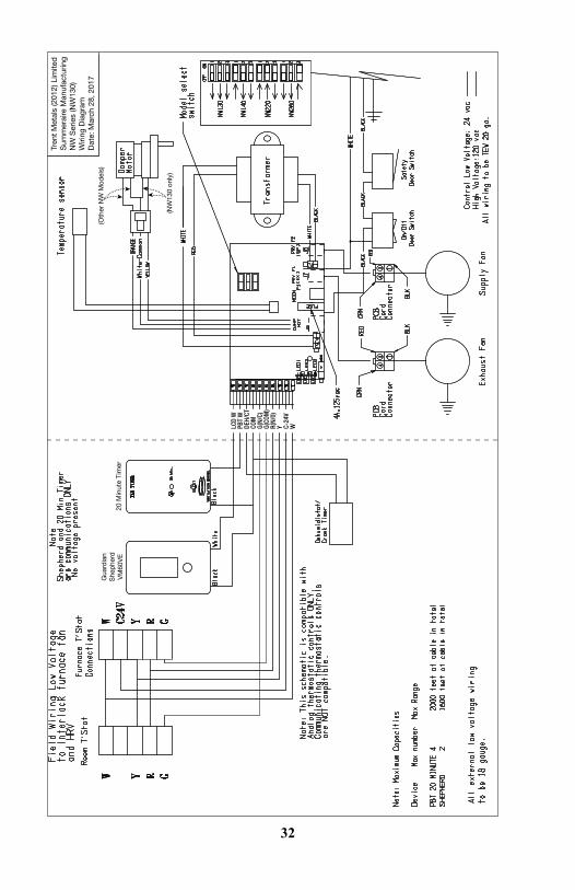
Tren
t M
etal
s (2
012)
Lim
ited
Sum
mer
aire
Man
ufac
turin
gN
W S
erie
s (N
W13
0)W
iring
Dia
gram
Dat
e: M
arch
28,
201
7(O
ther
NW
Mod
els)
Gua
rdia
nS
hep
herd
VM
60V
E20
Min
ute
Tim
er
(NW
130
only
)
LCD
WPB
T W
DEH/
CTCO
MG(
N/C)
G(CO
M)
R(N/
0)Y C-
24V
W
33
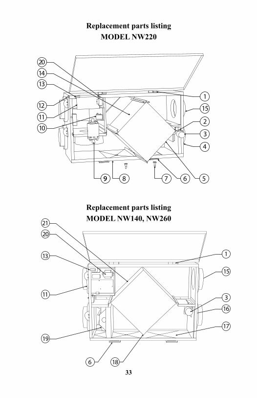
Replacement parts listingMODEL NW220
Replacement parts listingMODEL NW140, NW260
6 18
21
20
13
11
19
17
16
3
1
15
20
99 8 7 6 5
14
13
12
4
3
2
1
11
10
15
34
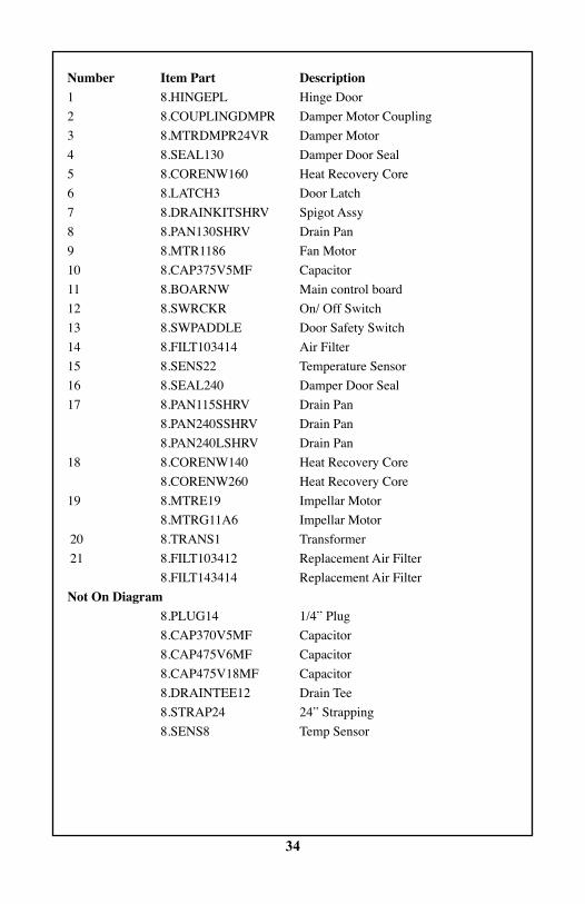
Number item part Description1 8.HINGEPL Hinge Door2 8.COUPLINGDMPR Damper Motor Coupling3 8.MTRDMPR24VR Damper Motor4 8.SEAL130 Damper Door Seal5 8.CORENW160 Heat Recovery Core6 8.LATCH3 Door Latch7 8.DRAINKITSHRV Spigot Assy8 8.PAN130SHRV Drain Pan9 8.MTR1186 Fan Motor10 8.CAP375V5MF Capacitor11 8.BOARNW Main control board12 8.SWRCKR On/ Off Switch13 8.SWPADDLE Door Safety Switch14 8.FILT103414 Air Filter15 8.SENS22 Temperature Sensor16 8.SEAL240 Damper Door Seal17 8.PAN115SHRV Drain Pan 8.PAN240SSHRV Drain Pan 8.PAN240LSHRV Drain Pan18 8.CORENW140 Heat Recovery Core 8.CORENW260 Heat Recovery Core19 8.MTRE19 Impellar Motor
8.MTRG11A6 Impellar Motor20 8.TRANS1 Transformer21 8.FILT103412 Replacement Air Filter 8.FILT143414 Replacement Air FilterNot On Diagram 8.PLUG14 1/4” Plug 8.CAP370V5MF Capacitor 8.CAP475V6MF Capacitor 8.CAP475V18MF Capacitor 8.DRAINTEE12 Drain Tee 8.STRAP24 24” Strapping 8.SENS8 Temp Sensor
Summeraire Mfg.Peterborough, Ontario
Canada, K9J 6X6
Built Better To Last Longer
WARRANTYHRV unit
Summeraire Mfg. warrants the entire Heat Recovery Ventilator to the original purchaser should it prove to be defective by reason of defective material and or faulty workmanship with in two (2) years of the install date. Extended warranties are offered for the “Core” and “Electrical components” as outlined below.
Core
Summeraire Mfg. warrants the “Core” of the Heat Recovery Ventilator to the original purchaser if the core has become defective by reason of defective material and/or faulty workmanship. This warranty applies to the original purchaser of the Heat Recovery Ventilator for as long as they own the dwelling.
Electrical Components
Summeraire Mfg. warrants the “Electrical components” of the Heat Recovery Ventilator to the original purchaser if any of the electrical components have become faulty by reason of defective material and/or faulty workmanship. This warranty applies to the original purchaser of the Heat Recovery Ventilator for a period of five (5) years from the date of install as long as they own the dwelling.
gENERAL pROVisiONs
Summeraire Mfg. will supply a replacement HRV unit or component as prescribed in the forgoing section, F.O.B. Peterborough, Ontario, Canada. Replacement units and/ or components are warranted for the remainder of the original warranty period.
This warranty does not cover defects caused by: modifications, alteration, abuse to, or misuse of the product or it’s operation in a manner contrary to the instructions included with the unit at the time of shipment, or failure to perform maintenance as detailed in aforementioned instructions.
This warranty expressly supersedes all other warranties and obligations of Summeraire Mfg.. No person has authority to alter or modify the terms of this warranty in any matter.
This warranty does not include any freight, labour, including diagnostic labour, or sales tax that might be incurred by the purchaser if a unit and or parts require replacement.
Under no circumstances shall Summeraire Mfg. be liable to the purchaser or any other person(s) for any consequential damages, whether arising out of breach of warranty, breach of contract, negligence or otherwise.
Keep your warranty at work for you. Please complete and mail your warranty Registration Card to Summeraire Mfg., 2040 Fisher Drive, Peterborough, Ontario, Canada, K9J 6X6 to register this warranty.
X-NW130/140/220/260-INSMAN-EN_REV57Specifications and illustrations subject to change without notice and without incurring obligations.