Embed Size (px)
Citation preview
Part Number: 150133-1CDRevision: 8
MANUAL NO. 17RE-CHO-A104
NX100MAINTENANCE MANUAL
Upon receipt of the product and prior to initial operation, read these instructions thoroughly, and retain for future reference.
MOTOMAN INSTRUCTIONS
MOTOMAN- INSTRUCTIONSNX100 INSTRUCTIONSNX100 OPERATOR’S MANUALNX100 MAINTENANCE MANUAL
The NX100 operator’s manuals above correspond to specific usage. Be sure to use the appropriate manual.
1 of 292
150133-1CD
RE-CHO-A104
NX100 Maintenance
Copyright © 2015, Yaskawa America, Inc.
Terms of Use and Copyright Notice
All rights reserved. This manual is freely available as a service to Yaskawa customers to assist in the operation of Motoman robots, related equipment and software This manual is copyrighted property of Yaskawa and may not be sold or redistributed in any way. You are welcome to copy this document to your computer or mobile device for easy access but you may not copy the PDF files to another website, blog, cloud storage site or any other means of storing or distributing online content.
Printed in the United States of America
First Printing, 2015
Yaskawa America, Inc. Motoman Robotics Division 100 Automation Way Miamisburg, OH 45342 Phone: 937-847-6200
www.motoman.com
2 of 292
iii
150133-1CD
RE-CHO-A104
NX100 Maintenance
• This manual explains maintenance procedures of the NX100 system. Read this manual carefully and be sure to understand its contents before handling the NX100.
• General items related to safety are listed in Section 1: Safety of the NX100 Instructions. To ensure correct and safe operation, carefully read the NX100 Instructions before reading this manual.
• Some drawings in this manual are shown with the protective covers or shields removed for clarity. Be sure all covers and shields are replaced before operating this product.
• The drawings and photos in this manual are representative examples and differences may exist between them and the delivered product.
• YASKAWA may modify this model without notice when necessary due to product improvements, modifications, or changes in specifications. If such modification is made, the manual number will also be revised.
• If your copy of the manual is damaged or lost, contact a YASKAWA representative to order a new copy. The representatives are listed on the back cover. Be sure to tell the representative the manual number listed on the front cover.
• YASKAWA is not responsible for incidents arising from unauthorized modification of its products. Unauthorized modification voids your product’s warranty.
3 of 292
iv
150133-1CD
RE-CHO-A104
NX100 Maintenance
We suggest that you obtain and review a copy of the ANSI/RIA National Safety Standard for Industrial Robots and Robot Systems (ANSI/RIA R15.06-2012). You can obtain this document from the Robotic Industries Association (RIA) at the following address:
Robotic Industries Association900 Victors WayP.O. Box 3724
Ann Arbor, Michigan 48106TEL: (734) 994-6088FAX: (734) 994-3338
www.roboticsonline.com
Ultimately, well-trained personnel are the best safeguard against accidents and damage that can result from improper operation of the equipment. The customer is responsible for providing adequately trained personnel to operate, program, and maintain the equipment. NEVER ALLOW UNTRAINED PERSONNEL TO OPERATE, PROGRAM, OR REPAIR THE EQUIPMENT!
We recommend approved Yaskawa training courses for all personnel involved with the operation, programming, or repair of the equipment.
This equipment has been tested and found to comply with the limits for a Class A digital device, pursuant to part 15 of the FCC rules. These limits are designed to provide reasonable protection against harmful interference when the equipment is operated in a commercial environment. This equipment generates, uses, and can radiate radio frequency energy and, if not installed and used in accordance with the instruction manual, may cause harmful interference to radio communications.
4 of 292
v
150133-1CD
RE-CHO-A104
NX100 Maintenance
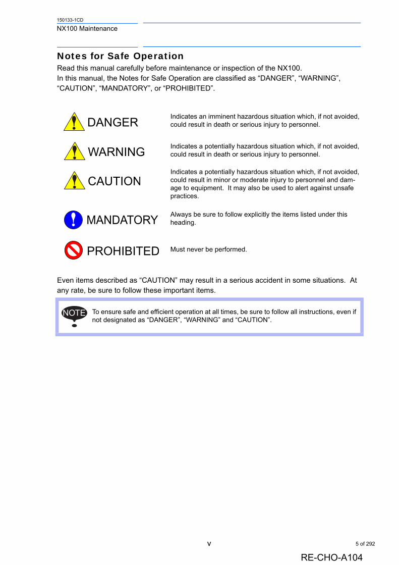
Notes for Safe OperationRead this manual carefully before maintenance or inspection of the NX100. In this manual, the Notes for Safe Operation are classified as “DANGER”, “WARNING”, “CAUTION”, “MANDATORY”, or “PROHIBITED”.
Even items described as “CAUTION” may result in a serious accident in some situations. At any rate, be sure to follow these important items.
Indicates an imminent hazardous situation which, if not avoided, could result in death or serious injury to personnel.
Indicates a potentially hazardous situation which, if not avoided, could result in death or serious injury to personnel.
Indicates a potentially hazardous situation which, if not avoided, could result in minor or moderate injury to personnel and dam-age to equipment. It may also be used to alert against unsafe practices.
Always be sure to follow explicitly the items listed under this heading.
Must never be performed.
To ensure safe and efficient operation at all times, be sure to follow all instructions, even if not designated as “DANGER”, “WARNING” and “CAUTION”.
NOTE
5 of 292
vi
150133-1CD
RE-CHO-A104
NX100 Maintenance
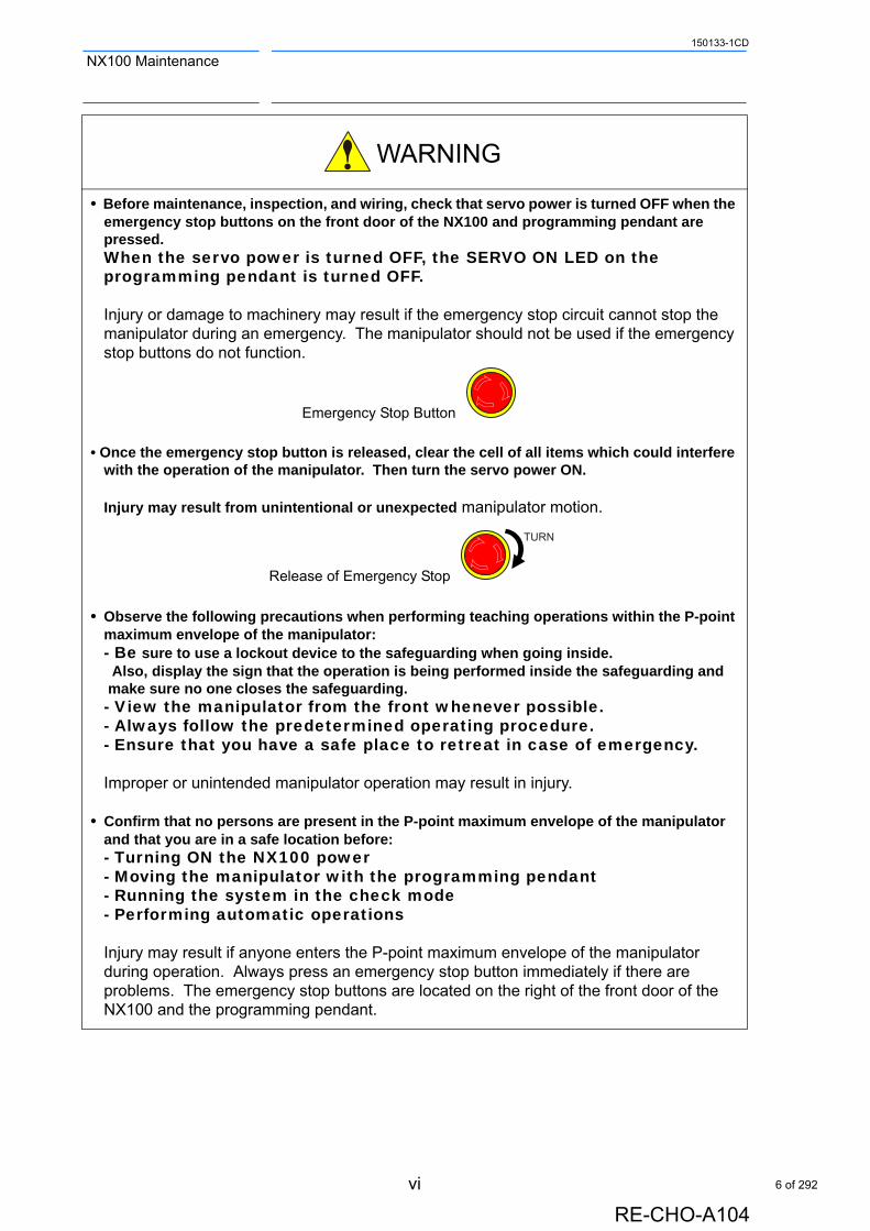
• Before maintenance, inspection, and wiring, check that servo power is turned OFF when the emergency stop buttons on the front door of the NX100 and programming pendant are pressed. When the servo power is turned OFF, the SERVO ON LED on the programming pendant is turned OFF.
Injury or damage to machinery may result if the emergency stop circuit cannot stop the manipulator during an emergency. The manipulator should not be used if the emergency stop buttons do not function.
Emergency Stop Button
• Once the emergency stop button is released, clear the cell of all items which could interfere with the operation of the manipulator. Then turn the servo power ON.
Injury may result from unintentional or unexpected manipulator motion.
Release of Emergency Stop
• Observe the following precautions when performing teaching operations within the P-point maximum envelope of the manipulator: - Be sure to use a lockout device to the safeguarding when going inside. Also, display the sign that the operation is being performed inside the safeguarding and make sure no one closes the safeguarding. - View the manipulator from the front whenever possible. - Always follow the predetermined operating procedure. - Ensure that you have a safe place to retreat in case of emergency.
Improper or unintended manipulator operation may result in injury.
• Confirm that no persons are present in the P-point maximum envelope of the manipulator and that you are in a safe location before: - Turning ON the NX100 power - Moving the manipulator with the programming pendant - Running the system in the check mode - Performing automatic operations
Injury may result if anyone enters the P-point maximum envelope of the manipulator during operation. Always press an emergency stop button immediately if there are problems. The emergency stop buttons are located on the right of the front door of the NX100 and the programming pendant.
TURN
6 of 292

vii
150133-1CD
RE-CHO-A104
NX100 Maintenance
Definition of Terms Used Often in This ManualThe MOTOMAN is the YASKAWA industrial robot product.The MOTOMAN usually consists of the manipulator, the controller, the programming pendant, and manipulator cables.In this manual, the equipment is designated as follows:
• Perform the following inspection procedures prior to conducting manipulator teaching. If problems are found, repair them immediately, and be sure that all other necessary processing has been performed. -Check for problems in manipulator movement. -Check for damage to insulation and sheathing of external wires.
• Always return the programming pendant to the hook on the NX100 cabinet after use.
The programming pendant can be damaged if it is left in the P-point maximum envelope of the manipulator, on the floor, or near fixtures.
• Read and understand the Explanation of Warning Labels in the NX100 Instructions before operating the manipulator.
Equipment Manual Designation
NX100 Controller NX100
NX100 Programming Pendant Programming Pendant
Cable between the manipulator and the controller Manipulator cable
7 of 292
viii
150133-1CD
RE-CHO-A104
NX100 Maintenance
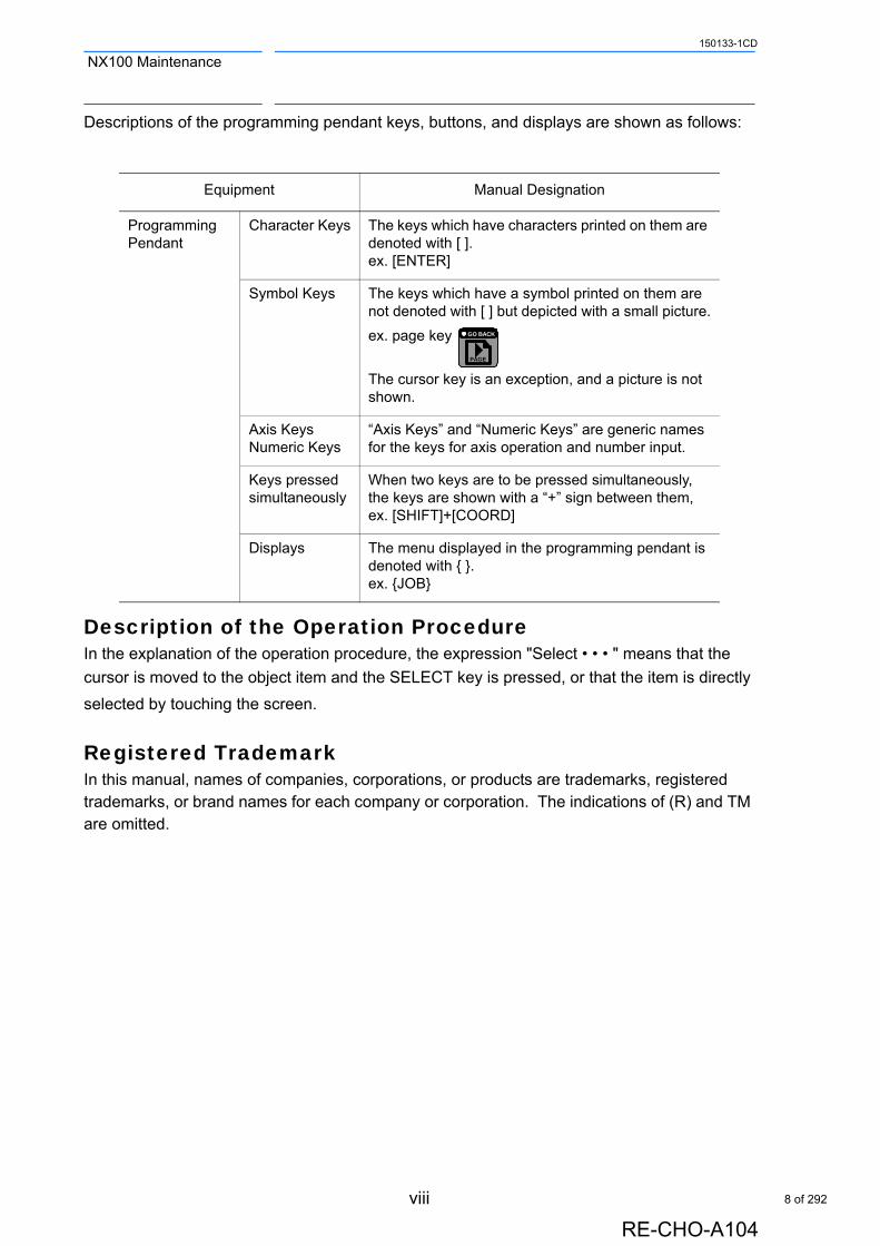
Descriptions of the programming pendant keys, buttons, and displays are shown as follows:
Description of the Operation ProcedureIn the explanation of the operation procedure, the expression "Select • • • " means that the
cursor is moved to the object item and the SELECT key is pressed, or that the item is directly
selected by touching the screen.
Registered TrademarkIn this manual, names of companies, corporations, or products are trademarks, registered trademarks, or brand names for each company or corporation. The indications of (R) and TM are omitted.
Equipment Manual Designation
Programming Pendant
Character Keys The keys which have characters printed on them are denoted with [ ].ex. [ENTER]
Symbol Keys The keys which have a symbol printed on them are not denoted with [ ] but depicted with a small picture.
ex. page key
The cursor key is an exception, and a picture is not shown.
Axis KeysNumeric Keys
“Axis Keys” and “Numeric Keys” are generic names for the keys for axis operation and number input.
Keys pressed simultaneously
When two keys are to be pressed simultaneously, the keys are shown with a “+” sign between them, ex. [SHIFT]+[COORD]
Displays The menu displayed in the programming pendant is denoted with { }.ex. {JOB}
PAGE
GO BACK
8 of 292
ix
150133-1CD
RE-CHO-A104
NX100 Maintenance
Customer Support InformationIf you need assistance with any aspect of your NX100 Maintenance system, please contact Motoman Customer Support at the following 24-hour telephone number:
For routine technical inquiries, you can also contact Motoman Customer Support at the following e-mail address:
When using e-mail to contact Motoman Customer Support, please provide a detailed description of your issue, along with complete contact information. Please allow approximately 24 to 36 hours for a response to your inquiry.
Please have the following information ready before you call:
(937) 847-3200
NOTEPlease use e-mail for routine inquiries only. If you have an urgent or emergency need for service, replacement parts, or information, you must contact Motoman Customer Support at the telephone number shown above.
• System NX100 Maintenance
• Robots
• Primary Application
• Controller NX100
• Software Version Access this information on the Programming Pendant’s LCD display screen by selecting {MAIN MENU} - {SYSTEM INFO} - {VERSION}
• Robot Serial Number Located on the robot data plate
• Robot Sales Order Number Located on the NX100 controller data plate
9 of 292
Table of Contents
x
150133-1CD
RE-CHO-A104
NX100 Maintenance
Table of Contents
1 Equipment Configuration1.1 Arrangement of Units and Circuit Boards . . . . . . . . . . . 1-1
1.2 Power Flow . . . . . . . . . . . . . . . . . . . . . . . . . . . . . . . . . . . . . . . . 1-3
1.3 Signal Flow . . . . . . . . . . . . . . . . . . . . . . . . . . . . . . . . . . . . . . . . 1-4
2 Security System2.1 Protection Through Security Mode Settings. . . . . . . . . 2-1
2.1.1 Security Mode. . . . . . . . . . . . . . . . . . . . . . . . . . . . . . . . . . . . . . 2-1 Changing the Security Mode . . . . . . . . . . . . . . . . . . . . . . . . 2-6
2.1.2 User ID . . . . . . . . . . . . . . . . . . . . . . . . . . . . . . . . . . . . . . . . . . . 2-8 Changing a User ID . . . . . . . . . . . . . . . . . . . . . . . . . . . . . . . 2-8
3 Inspections3.1 Regular Inspections . . . . . . . . . . . . . . . . . . . . . . . . . . . . . . . . 3-1
3.2 NX100 Inspections . . . . . . . . . . . . . . . . . . . . . . . . . . . . . . . . . 3-23.2.1 Checking if the Doors are Firmly Closed . . . . . . . . . . . . . . . . . 3-23.2.2 Checking for Gaps or Damage in the
Sealed Construction Section . . . . . . . . . . . . . . . . . . . . . . . . . . 3-2
3.3 Cooling Fan Inspections . . . . . . . . . . . . . . . . . . . . . . . . . . . 3-3
3.4 Emergency Stop Button Inspections . . . . . . . . . . . . . . . . 3-5
3.5 Enable Switch Inspections . . . . . . . . . . . . . . . . . . . . . . . . . 3-5
3.6 Battery Inspections. . . . . . . . . . . . . . . . . . . . . . . . . . . . . . . . . 3-6
3.7 Power Supply Voltage Confirmation . . . . . . . . . . . . . . . . 3-6
3.8 Open Phase Check . . . . . . . . . . . . . . . . . . . . . . . . . . . . . . . . 3-7
4 Preparation before Replacing Parts4.1 Creating a Check Program . . . . . . . . . . . . . . . . . . . . . . . . . 4-3
10 of 292
xi
150133-1CD
RE-CHO-A104
NX100 Maintenance Table of Contents
5 Replacing Parts5.1 Replacing NX100 Parts . . . . . . . . . . . . . . . . . . . . . . . . . . . . 5-1
5.1.1 Replacing Parts of the CPU Unit . . . . . . . . . . . . . . . . . . . . . . . .5-2 Replacing the Battery . . . . . . . . . . . . . . . . . . . . . . . . . . . . . .5-3 Replacing the Control Circuit Board (JANCD-NCP01) . . . . .5-3 Replacing the Control Power Supply (CPS-420F). . . . . . . . .5-4
Replacing the Servo Control Circuit Board (SGDR-AXA01A). . . . . . . . . . . . . . . . . . . . . . . . . . . . . . . . . .5-5
Replacing the Robot I/F Unit (JZNC-NIF01o) . . . . . . . . . . . .5-6 Replacing the Robot I/F Circuit Board (JANCD-NIF01). . . . .5-8 Replacing the I/O Circuit Board (JANCD-NIO01o) . . . . . . . .5-9
5.1.2 Replacing the SERVOPACK . . . . . . . . . . . . . . . . . . . . . . . . . .5-105.1.3 Checking and Replacing Fuses. . . . . . . . . . . . . . . . . . . . . . . .5-13
Power Supply Contactor Unit . . . . . . . . . . . . . . . . . . . . . . .5-13 Robot I/F Unit . . . . . . . . . . . . . . . . . . . . . . . . . . . . . . . . . . .5-14
5.2 NX100 Parts List . . . . . . . . . . . . . . . . . . . . . . . . . . . . . . . . . 5-15
5.3 Supplied Parts List . . . . . . . . . . . . . . . . . . . . . . . . . . . . . . . 5-18
5.4 Recommended Spare Parts . . . . . . . . . . . . . . . . . . . . . . 5-18
6 Operations after Replacing Parts6.1 Home Position Calibration . . . . . . . . . . . . . . . . . . . . . . . . . 6-2
6.1.1 Home Position Calibration . . . . . . . . . . . . . . . . . . . . . . . . . . . . .6-26.1.2 Calibrating Operation. . . . . . . . . . . . . . . . . . . . . . . . . . . . . . . . .6-3
Registering All Axes at One Time . . . . . . . . . . . . . . . . . . . . .6-3 Registering Individual Axes . . . . . . . . . . . . . . . . . . . . . . . . . .6-6 Changing the Absolute Data . . . . . . . . . . . . . . . . . . . . . . . . .6-7 Clearing Absolute Data . . . . . . . . . . . . . . . . . . . . . . . . . . . . .6-8
6.1.3 Manipulator Home Position . . . . . . . . . . . . . . . . . . . . . . . . . . . .6-9
6.2 Position Deviation Check Using the Check Program . . . . . . . . . . . . . . . . . . . . . . . . . . . . . . . 6-10
6.3 Home Position Data Correction . . . . . . . . . . . . . . . . . . . 6-11
6.4 Setting the Second Home Position (Check Point) . 6-12
6.4.1 Purpose of Position Check Operation . . . . . . . . . . . . . . . . . . .6-146.4.2 Procedure for the Second Home Position Setting
(Check Point). . . . . . . . . . . . . . . . . . . . . . . . . . . . . . . . . . . . . .6-166.4.3 Procedure after the Alarm . . . . . . . . . . . . . . . . . . . . . . . . . . . .6-17
11 of 292
Table of Contents
xii
150133-1CD
RE-CHO-A104
NX100 Maintenance
7 System Diagnosis7.1 System Version . . . . . . . . . . . . . . . . . . . . . . . . . . . . . . . . . . . . 7-1
7.2 Manipulator Model . . . . . . . . . . . . . . . . . . . . . . . . . . . . . . . . . 7-2
7.3 Input/Output Status . . . . . . . . . . . . . . . . . . . . . . . . . . . . . . . . 7-37.3.1 Universal Input . . . . . . . . . . . . . . . . . . . . . . . . . . . . . . . . . . . . . 7-3
Universal Input Window . . . . . . . . . . . . . . . . . . . . . . . . . . . . 7-3 Universal Input Simple Window . . . . . . . . . . . . . . . . . . . . . . 7-3
7.3.2 Universal Output . . . . . . . . . . . . . . . . . . . . . . . . . . . . . . . . . . . . 7-4 Universal Output Window . . . . . . . . . . . . . . . . . . . . . . . . . . . 7-4 Universal Output Simple Window . . . . . . . . . . . . . . . . . . . . . 7-4 Modifying the Output Status . . . . . . . . . . . . . . . . . . . . . . . . . 7-5
7.3.3 Specific Input . . . . . . . . . . . . . . . . . . . . . . . . . . . . . . . . . . . . . . 7-6 Specific Input Window . . . . . . . . . . . . . . . . . . . . . . . . . . . . . 7-6 Specific Input Simple Window . . . . . . . . . . . . . . . . . . . . . . . 7-6
7.3.4 Specific Output . . . . . . . . . . . . . . . . . . . . . . . . . . . . . . . . . . . . . 7-7 Specific Output Window . . . . . . . . . . . . . . . . . . . . . . . . . . . . 7-7 Specific Output Simple Window . . . . . . . . . . . . . . . . . . . . . . 7-7
7.3.5 RIN Input. . . . . . . . . . . . . . . . . . . . . . . . . . . . . . . . . . . . . . . . . . 7-8 RIN Input Window. . . . . . . . . . . . . . . . . . . . . . . . . . . . . . . . . 7-8
7.3.6 Signal Number Search . . . . . . . . . . . . . . . . . . . . . . . . . . . . . . . 7-9 Direct Search on the Universal/Specified Input/Output
Window. . . . . . . . . . . . . . . . . . . . . . . . . . . . . . . . . . . . . . . . 7-10 Search from the Menu . . . . . . . . . . . . . . . . . . . . . . . . . . . . 7-11
7.3.7 Relay Number Search . . . . . . . . . . . . . . . . . . . . . . . . . . . . . . 7-12 Direct Search on the Universal/Specified Input/Output
Window. . . . . . . . . . . . . . . . . . . . . . . . . . . . . . . . . . . . . . . . 7-13 Search from the Menu . . . . . . . . . . . . . . . . . . . . . . . . . . . . 7-14
7.3.8 Modification of the Signal Name . . . . . . . . . . . . . . . . . . . . . . . 7-15 Direct Modification on the Universal/Specified
Input/Output Window . . . . . . . . . . . . . . . . . . . . . . . . . . . . . 7-15 Modification from the Menu . . . . . . . . . . . . . . . . . . . . . . . . 7-16
7.4 System Monitoring Time Display . . . . . . . . . . . . . . . . . . 7-17
7.4.1 System Monitoring Time Display Window. . . . . . . . . . . . . . . . 7-177.4.2 Individual Window of the System Monitoring Time Display . . 7-187.4.3 Clearing the System Monitoring Time Display . . . . . . . . . . . . 7-19
7.5 Alarm History . . . . . . . . . . . . . . . . . . . . . . . . . . . . . . . . . . . . . 7-20
7.5.1 Alarm History Window . . . . . . . . . . . . . . . . . . . . . . . . . . . . . . 7-207.5.2 Clearing the Alarm History . . . . . . . . . . . . . . . . . . . . . . . . . . . 7-21
7.6 I/O Message History . . . . . . . . . . . . . . . . . . . . . . . . . . . . . . 7-22
7.6.1 I/O Message History Window . . . . . . . . . . . . . . . . . . . . . . . . . 7-22 Search . . . . . . . . . . . . . . . . . . . . . . . . . . . . . . . . . . . . . . . . 7-22
7.6.2 Clearing the I/O Message History. . . . . . . . . . . . . . . . . . . . . . 7-23
7.7 Position Data When Power is Turned ON/OFF . . . . 7-24
7.7.1 Power ON/OFF Position Window . . . . . . . . . . . . . . . . . . . . . . 7-24
7.8 Current Position . . . . . . . . . . . . . . . . . . . . . . . . . . . . . . . . . . . 7-25
7.8.1 Current Position Window . . . . . . . . . . . . . . . . . . . . . . . . . . . . 7-25
12 of 292
xiii
150133-1CD
RE-CHO-A104
NX100 Maintenance Table of Contents
7.9 Servo Monitoring . . . . . . . . . . . . . . . . . . . . . . . . . . . . . . . . . 7-26
7.9.1 Servo Monitor Window . . . . . . . . . . . . . . . . . . . . . . . . . . . . . .7-267.9.2 Changing the Monitor Items . . . . . . . . . . . . . . . . . . . . . . . . . .7-277.9.3 Clearing Maximum Torque Data . . . . . . . . . . . . . . . . . . . . . . .7-28
8 Alarm8.1 Outline of Alarm . . . . . . . . . . . . . . . . . . . . . . . . . . . . . . . . . . . 8-1
8.2 Alarm Display . . . . . . . . . . . . . . . . . . . . . . . . . . . . . . . . . . . . . 8-28.2.1 Displaying and Releasing Alarm . . . . . . . . . . . . . . . . . . . . . . . .8-2
Releasing Alarms . . . . . . . . . . . . . . . . . . . . . . . . . . . . . . . . .8-28.2.2 Special Alarm Display . . . . . . . . . . . . . . . . . . . . . . . . . . . . . . . .8-3
Sub Data . . . . . . . . . . . . . . . . . . . . . . . . . . . . . . . . . . . . . . . .8-3 Multiple SERVOPACK System . . . . . . . . . . . . . . . . . . . . . . .8-3 Independent Control Function (Optional) . . . . . . . . . . . . . . .8-4
8.3 Alarm Message List . . . . . . . . . . . . . . . . . . . . . . . . . . . . . . . 8-5
8.4 Confirming Method for Settings and Connection of Axis Configuration, Amplifier, Motor, and Converter, etc.of the System . . . . . . . . . 8-116
8.4.1 Data Backup . . . . . . . . . . . . . . . . . . . . . . . . . . . . . . . . . . . . .8-1168.4.2 System Setting Window Displaying Method
in the Maintenance Mode . . . . . . . . . . . . . . . . . . . . . . . . . . .8-1198.4.3 Confirmation of Servo Control Board Settings. . . . . . . . . . . .8-121
Confirmation on the Setting Window . . . . . . . . . . . . . . . . .8-121 Confirmation Using Hardware . . . . . . . . . . . . . . . . . . . . . .8-122
8.4.4 Confirmation of Servo Control Board Connector Settings . . .8-123 Confirmation on the Setting Window . . . . . . . . . . . . . . . . .8-123 Confirmation Using Hardware . . . . . . . . . . . . . . . . . . . . . .8-125
8.4.5 Confirmation of Amplifier Settings . . . . . . . . . . . . . . . . . . . . .8-126 Confirmation on the Setting Window . . . . . . . . . . . . . . . . .8-126 Confirmation Using Hardware . . . . . . . . . . . . . . . . . . . . . .8-127
8.4.6 Confirmation of Power Supply Contactor Unit Settings . . . . .8-129 Confirmation on the Setting Window . . . . . . . . . . . . . . . . .8-129 Confirmation Using Hardware . . . . . . . . . . . . . . . . . . . . . .8-130
8.4.7 Confirmation of Brake Wirings. . . . . . . . . . . . . . . . . . . . . . . .8-131 Confirmation on the Setting Window . . . . . . . . . . . . . . . . .8-131 Confirmation Using Hardware . . . . . . . . . . . . . . . . . . . . . .8-132
8.4.8 Confirmation of the Converter Settings . . . . . . . . . . . . . . . . .8-133 Confirmation on the Setting Window . . . . . . . . . . . . . . . . .8-133 Confirmation Using Hardware . . . . . . . . . . . . . . . . . . . . . .8-134
13 of 292
Table of Contents
xiv
150133-1CD
RE-CHO-A104
NX100 Maintenance
9 Error9.1 Error Message List . . . . . . . . . . . . . . . . . . . . . . . . . . . . . . . . . 9-1
9.1.1 System and General Operation . . . . . . . . . . . . . . . . . . . . . . . . 9-29.1.2 Editing. . . . . . . . . . . . . . . . . . . . . . . . . . . . . . . . . . . . . . . . . . . . 9-89.1.3 Job Defined Data . . . . . . . . . . . . . . . . . . . . . . . . . . . . . . . . . . . 9-99.1.4 External Memory Equipment . . . . . . . . . . . . . . . . . . . . . . . . . 9-139.1.5 Concurrent I/O . . . . . . . . . . . . . . . . . . . . . . . . . . . . . . . . . . . . 9-239.1.6 User Registration and Other Operations . . . . . . . . . . . . . . . . 9-249.1.7 Maintenance Mode . . . . . . . . . . . . . . . . . . . . . . . . . . . . . . . . . 9-26
10 LED Indicator on Circuit Board10.1 LED Indicator on NCP 01 Circuit Board . . . . . . . . . . 10-1
10.2 LED Indicator on Robot I/F Unit . . . . . . . . . . . . . . . . . . 10-2
10.3 7 SEG-LED Indicator . . . . . . . . . . . . . . . . . . . . . . . . . . . . 10-3 7 SEG-LED Indicator Status (1-digit indication)
of Each Unit at Error Occurrence . . . . . . . . . . . . . . . . . . . . 10-4 7 SEG-LED Indicator Status (4 digit-indication)
of Each Unit at Error Occurrence . . . . . . . . . . . . . . . . . . . . 10-6
14 of 292

1 Equipment Configuration1.1 Arrangement of Units and Circuit Boards
150133-1CD
1 Equipment Configuration
The NX100 is comprised of individual units and modules (circuit boards). Malfunctioning components can generally be easily repaired after a failure by replacing a unit or a module. This section explains the configuration of the NX100 equipment.
1.1 Arrangement of Units and Circuit Boards
The arrangements of units and circuit boards in small-capacity, medium-capacity, and large-capacity NX100s are shown.
1.1.1 Small Capacity
Configuration 1 for Small-Capacity NX100
Sectional View A-A'
Emergency stop button:AR22V2R-04RMajor axes control
circuit board:SGDR-AXA01A
Control power supply:CPS-420F
Robot I/F unit:JZNC-NIF01�
Welding circuit board:JANCD-XEW02
CPU unit:JZNC-NRK01
SERVOPACK:Refer to thefollowing table.
Interior circulation fan:4715MS-22T-B50-B00or 11938MB-B2N-EA-01
Breaker:Refer to thefollowing table.
Backside duct fan:4715MS-22T-B50-B00or 11938MB-B2N-EA-01(For air inlet)
Regenerative resistor:MRC22-125K-220W-12.5(220W,12.5W)
Power supplycontactor unit:Refer to thefollowing table
A
A'
(MXT)Robot system inputterminal block
Back View
(Air flows up)
(with removed cover)
Breaker
NF30SW 3P 10A
NX100Model
HP6ERCR-EA1400N-AA00
EA1400NSGDR-EA1400N
SERVOPACK (Converter Integrated)
Power Supply Contactor Unit
JZRCR-NTU01�-1
Type
HP3 ERCR-HP3-AA00 SGDR-EA1400NY26 NF30SW 3P 5A
1-1
RE-CHO-A104
15 of 292

1 Equipment Configuration1.1 Arrangement of Units and Circuit Boards
150133-1CD
Configuration 2 for Small-Capacity NX100
1.1.2 Medium or Large Capacity
Configuration for Medium- or Large-Capacity NX100
Emergency stop button:AR22V2R-04R
Control power supply:CPS-420F
Major axes controlcircuit board:SGDR-AXA01A
Robot I/F unit:JZNC-NIF01�
CPU unit:JZNC-NRK01
SERVOPACK:Refer to thefollowing table.
Converter:Refer to thefollowing table.
Interior circulation fan:4715MS-22T-B50-B00or 11938MB-B2N-EA-01(Air flows up)
(For air inlet)
Backside duct fan:4715MS-22T-B50-B00or 11938MB-B2N-EA-01
A'
Regenerative resistor:MRC22-125K-220W-12.5(220W,12.5W)
(MXT)Robot system inputterminal block
A
Sectional View A-A'
Breaker:Refer to thefollowing table.
Power supplycontactor unit:Refer to thefollowing table
Back View(with removed cover)
NF30SW 3P 15A
Converter
SGDR-COA080A01B
NX100
ERCR-HP20-AA00
Type
EA1900NSGDR-HP20Y30 JZRCR-NTU01�-1
BreakerModel
SERVOPACK Power Supply Contactor Unit
HP20
Emergency stop button:AR22V2R-04R
Major axes controlcircuit board:SGDR-AXA01AControl power supply:CPS-420F
ARobot I/F unit:JZNC-NIF01�
CPU unit:JZNC-NRK01
Interior circulation fan:4715MS-22T-B50-B00or 11938MB-B2N-EA-01
Converter:Refer to thefollowing table.
SERVOPACK:Refer to thefollowing table.
A'
(Air flows up)
Breaker:Refer to thefollowing table
Power supplycontactor unit:Refer to thefollowing table
(For air inlet)
Backside duct fan:5915PS-22T-B30-B00or 15038PB-B2L-EP-03
Regenerative resistor:RDC50N2R0JI200X3S(1500W,6W)
(MXT)Robot system inputterminal block
Back View(with removed cover)
Sectional View A-A'
SERVOPACK
JZRCR-NTU02�-1NF30SW 3P 30ASGDR-ES165N
SGDR-EH50Y24
SGDR-COA250A01B
NF30SW 3P 20A
HP165
ES165N
UP50N ERCR-UP50N-AA00
NX100 ConverterType BreakerModel Power Supply
Contactor Unit
ES200N
ES165RN
ES200RN
ERCR-ES200N-AA00
ERCR-ES165RN-AA00
ERCR-ES200RN-AA00SGDR-ES165NY28
ERCR-UP20MN-AA00 SGDR-EH50Y27
ERCR-ES165N-AA00
UP20MN
1-2
RE-CHO-A104
16 of 292
1 Equipment Configuration1.2 Power Flow
150133-1CD
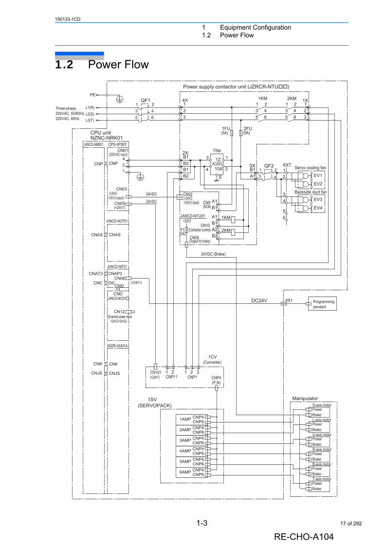
1.2 Power Flow
JANCD-NBB01 CPS-5P2EF
JANCD-NIF01
JANCD-NCP01
Programmingpendant
Manipulator
L-axis motor
S-axis motor
1AMP
T-axis motor
B-axis motor
R-axis motor
U-axis motor3AMP
4AMP
5AMP
6AMP
2AMP
SGDR-AXA01A
JANCD-NIO01
1SV(SERVOPACK)
24
13
QF1
CN01
65L2(S)L1(R)
PE
L3(T)
431
24VDC
24VDC
CNPCNP
(+24V1)
+24V3 output)CN05
CN03(+24V2,
(+24V1)
CNASCNAS
CNCCNC
CNAT3 CNAP3
CND
CN06
(200VAC input)
X81
Power
PowerBrake
DC24V
CNP4
CNP4CNP6
PowerBrake
BrakePower
PowerBrake
BrakePower
CNP6CNP4CNP6CNP4CNP6CNP4
CNP4CNP6
CNP6
Brake
+24V2/+24VU)
CN12
CND
CNK
CNJS
CNK
CNJS
Three-phase,200VAC, 50/60Hz220VAC, 60Hz
(External power input(External power input(External power input
JANCD-NTU01
1CV(Converter)
(5A)F1
+24V3
(NCM)CN9 A1
B1
B1B2
1 2CNP11
EV1
EV2
124 2
1X
6 3
13
24
13
1KM
(5A)2FU
65 5
12
4X
1FU
Filter
3
(5A)
2KM
Servo cooling fan6XT
21
EV3
EV4
34
65
Backside duct fan
3X
A1B1
2KM
1KM
1
2
1Z3
4AC250V
E
10A
B1B2
B1A2
A1
(+24V2,CN02
+24V3 input)
CN10(Contactor control)
CN08(Output for brake)
24VDC (Brake)
B2
2X
31CNP1
2CNP4(P,N)
(+24V1)CN101
2
4
13
QF2
Power supply contactor unit (JZRCR-NTU)
CPU unitNZNC-NRK01
1-3
RE-CHO-A104
17 of 292
1 Equipment Configuration1.3 Signal Flow
150133-1CD
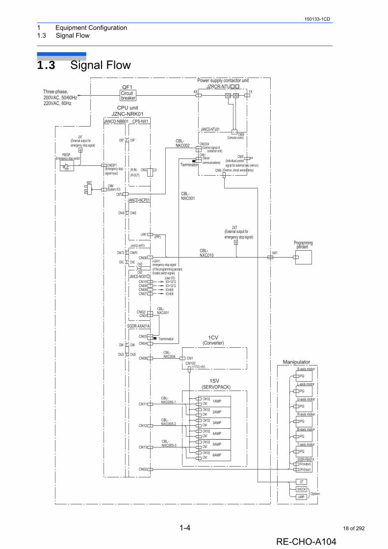
1.3 Signal Flow
Programmingpendant
Power supply contactor unitJZRCR-NTU
JANCD-NTU01
CPS-NX1JANCD-NBB01
CPU unitJZNC-NRK01
MXT
JANCD-NIF01
JANCD-NIO01
JANCD-NCP01
L-axis motor
S-axis motor
B-axis motor
R-axis motor
U-axis motor
Manipulator
SGDR-FBA01A
T-axis motor
1CV(Converter)
1SV(SERVOPACK)
1AMP
2AMP
3AMP
SGDR-AXA01A
5AMP
6AMP
4AMP
CBL-NXC004
CBL-NXC005-1
CBL-NXC005-2
CBL-NXC005-3
CBL-NXC001
1X2KM
CN09(Contactor control)
CN05
X81
2XT
1KM4X
CN03/04(Control signal of
QF1
CNP
200VAC, 50/60Hz220VAC, 60Hz
Three-phase,
(External output for emergency stop signal)
2XTCNP
Circuitbreaker
CN06
CN01
Terminator(Serial communications)
CN02
LAN1 (PP)
I/O=12/12I/O=8/8
I/O=12/12(User I/O)
CND
CND
CN09CN08
CN10
(+24V1,
Enable switch signal)
CN06
CNESP1(Emergency stop signal input)
(System I/O)CNTU
CNAS
CNM
PBESPEmergency stop switch
CNAT3
CNC CNC
CNAP3
CNAS
(R-IN)(R-OUT)
contactor unit)
(External output for emergency stop signal)
(Overrun, shock sensor lamp)
(Individual control signal for external axis overrun)
PG
PG
PG
PG
PG
PG
5V(output)
OT
SHOCK
LAMP
24V(input)
CN1
I/O=8/8CN07
CN01CN02/
TerminatorCN03
CN04
CN08
(+17V3,+5V)
CN1
CN1
CN1CN102
CN102
CN102
CN102CN11
CN12
CN102
CNJS
CNK
CNJS
CNK
CN1
CN1
CN1
CN102
CN102CN13
CN02
CBL-NKC002
CBL-NXC001
CBL-NXC010
emergency stop signal of the programming pendant,
Option
1-4
RE-CHO-A104
18 of 292

2 Security System2.1 Protection Through Security Mode Settings
150133-1CD
2 Security System
2.1 Protection Through Security Mode Settings
The NX100 modes setting are protected by a security system. The system allows operation and modification of settings according to operator clearance. Be sure operators have the correct level of training for each level to which they are granted access.
2.1.1 Security Mode
There are three security modes. Editing mode and management mode require a user ID. The user ID consists of numbers and letters, and contains no less than 4 and no more than 8 characters. (Significant numbers and signs: ”0 to 9”, “-”, “.”)
Security Mode Descriptions
Security Mode Explanation
Operation ModeThis mode allows basic operation of the robot (stopping, starting, etc.) for people operating the robot work on the line.
Editing Mode This mode allows the operator to teach and edit jobs and robot settings.
Management Mode
This mode allows those authorized to set up and maintain robot system: parameters, system time and modifying user IDs.
2-1
RE-CHO-A104
19 of 292
2 Security System2.1 Protection Through Security Mode Settings
150133-1CD
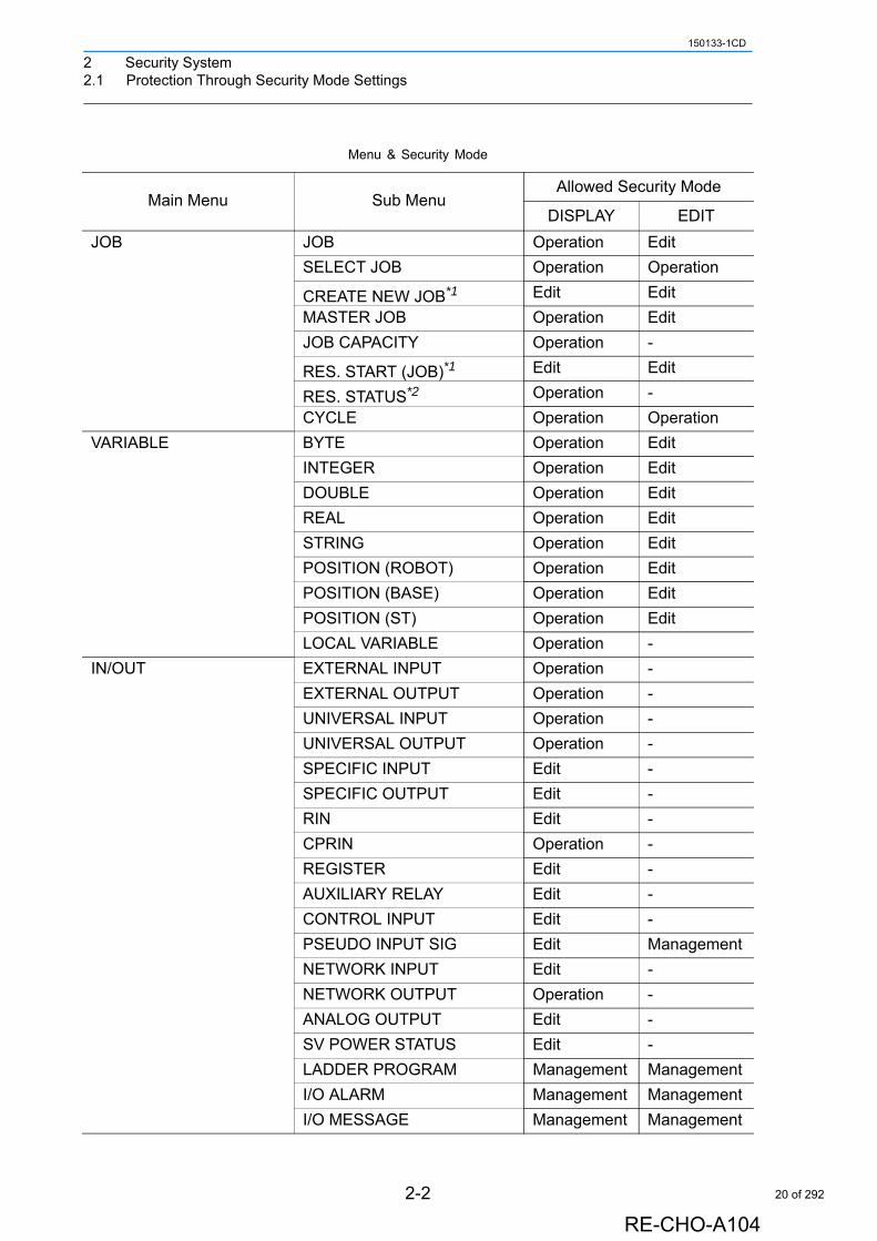
Menu & Security Mode
Main Menu Sub MenuAllowed Security Mode
DISPLAY EDIT
JOB JOB Operation Edit
SELECT JOB Operation Operation
CREATE NEW JOB*1 Edit Edit
MASTER JOB Operation Edit
JOB CAPACITY Operation -
RES. START (JOB)*1 Edit Edit
RES. STATUS*2 Operation -
CYCLE Operation Operation
VARIABLE BYTE Operation Edit
INTEGER Operation Edit
DOUBLE Operation Edit
REAL Operation Edit
STRING Operation Edit
POSITION (ROBOT) Operation Edit
POSITION (BASE) Operation Edit
POSITION (ST) Operation Edit
LOCAL VARIABLE Operation -
IN/OUT EXTERNAL INPUT Operation -
EXTERNAL OUTPUT Operation -
UNIVERSAL INPUT Operation -
UNIVERSAL OUTPUT Operation -
SPECIFIC INPUT Edit -
SPECIFIC OUTPUT Edit -
RIN Edit -
CPRIN Operation -
REGISTER Edit -
AUXILIARY RELAY Edit -
CONTROL INPUT Edit -
PSEUDO INPUT SIG Edit Management
NETWORK INPUT Edit -
NETWORK OUTPUT Operation -
ANALOG OUTPUT Edit -
SV POWER STATUS Edit -
LADDER PROGRAM Management Management
I/O ALARM Management Management
I/O MESSAGE Management Management
2-2
RE-CHO-A104
20 of 292
2 Security System2.1 Protection Through Security Mode Settings
150133-1CD
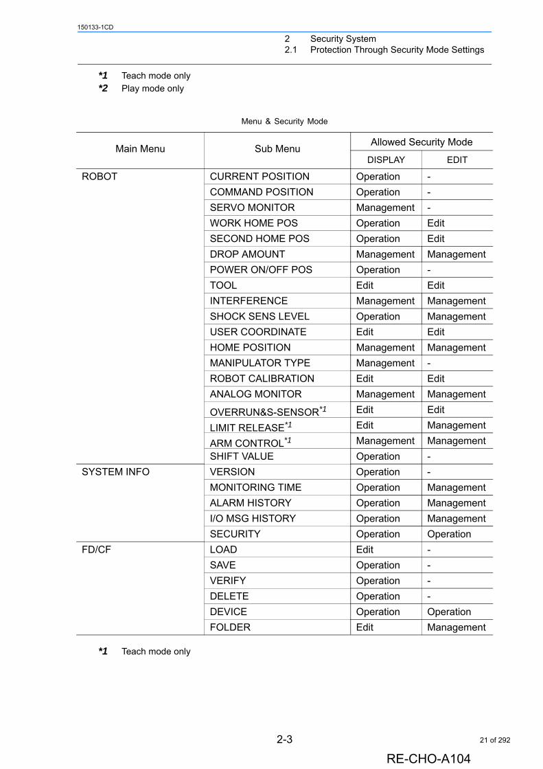
*1 Teach mode only
*2 Play mode only
*1 Teach mode only
Menu & Security Mode
Main Menu Sub MenuAllowed Security Mode
DISPLAY EDIT
ROBOT CURRENT POSITION Operation -
COMMAND POSITION Operation -
SERVO MONITOR Management -
WORK HOME POS Operation Edit
SECOND HOME POS Operation Edit
DROP AMOUNT Management Management
POWER ON/OFF POS Operation -
TOOL Edit Edit
INTERFERENCE Management Management
SHOCK SENS LEVEL Operation Management
USER COORDINATE Edit Edit
HOME POSITION Management Management
MANIPULATOR TYPE Management -
ROBOT CALIBRATION Edit Edit
ANALOG MONITOR Management Management
OVERRUN&S-SENSOR*1 Edit Edit
LIMIT RELEASE*1 Edit Management
ARM CONTROL*1 Management Management
SHIFT VALUE Operation -
SYSTEM INFO VERSION Operation -
MONITORING TIME Operation Management
ALARM HISTORY Operation Management
I/O MSG HISTORY Operation Management
SECURITY Operation Operation
FD/CF LOAD Edit -
SAVE Operation -
VERIFY Operation -
DELETE Operation -
DEVICE Operation Operation
FOLDER Edit Management
2-3
RE-CHO-A104
21 of 292
2 Security System2.1 Protection Through Security Mode Settings
150133-1CD
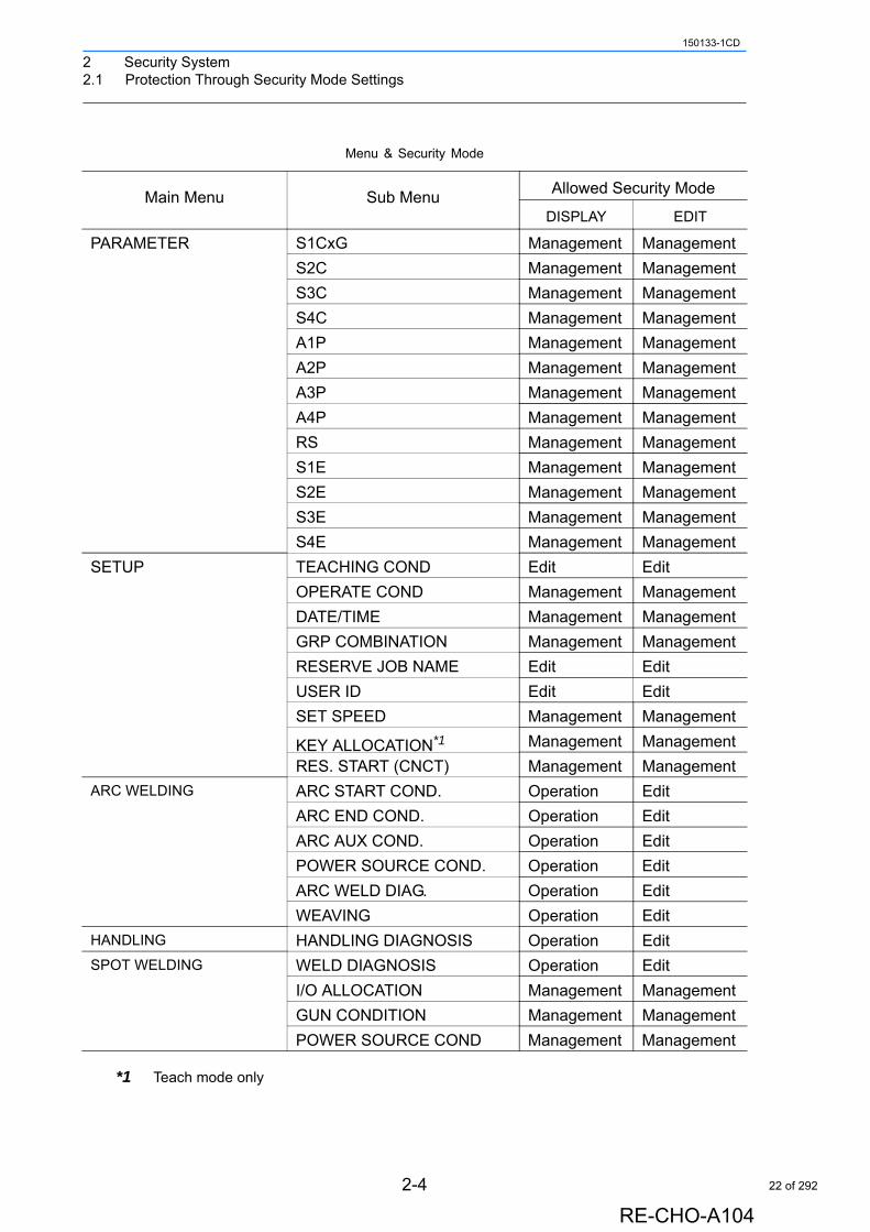
*1 Teach mode only
Menu & Security Mode
Main Menu Sub MenuAllowed Security Mode
DISPLAY EDIT
PARAMETER S1CxG Management Management
S2C Management Management
S3C Management Management
S4C Management Management
A1P Management Management
A2P Management Management
A3P Management Management
A4P Management Management
RS Management Management
S1E Management Management
S2E Management Management
S3E Management Management
S4E Management Management
SETUP TEACHING COND Edit Edit
OPERATE COND Management Management
DATE/TIME Management Management
GRP COMBINATION Management Management
RESERVE JOB NAME Edit Edit
USER ID Edit Edit
SET SPEED Management Management
KEY ALLOCATION*1 Management Management
RES. START (CNCT) Management Management
ARC WELDING ARC START COND. Operation Edit
ARC END COND. Operation Edit
ARC AUX COND. Operation Edit
POWER SOURCE COND. Operation Edit
ARC WELD DIAG. Operation Edit
WEAVING Operation Edit
HANDLING HANDLING DIAGNOSIS Operation Edit
SPOT WELDING WELD DIAGNOSIS Operation Edit
I/O ALLOCATION Management Management
GUN CONDITION Management Management
POWER SOURCE COND Management Management
2-4
RE-CHO-A104
22 of 292
2 Security System2.1 Protection Through Security Mode Settings
150133-1CD
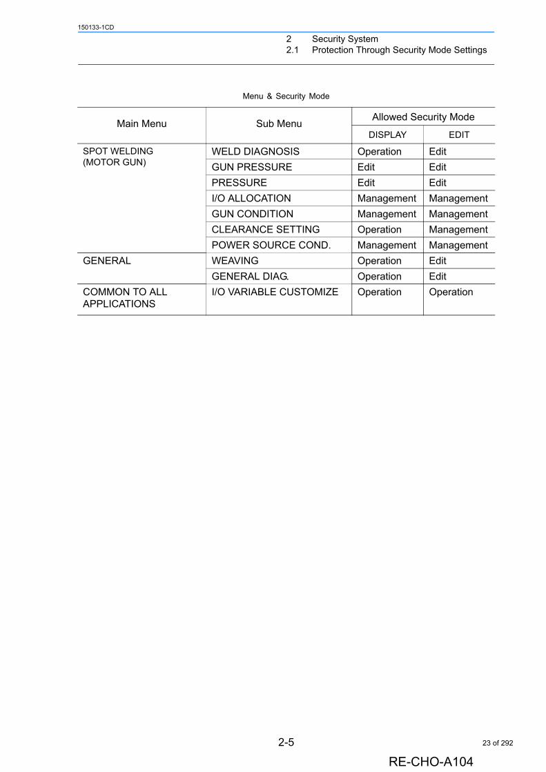
Menu & Security Mode
Main Menu Sub MenuAllowed Security Mode
DISPLAY EDIT
SPOT WELDING (MOTOR GUN)
WELD DIAGNOSIS Operation Edit
GUN PRESSURE Edit Edit
PRESSURE Edit Edit
I/O ALLOCATION Management Management
GUN CONDITION Management Management
CLEARANCE SETTING Operation Management
POWER SOURCE COND. Management Management
GENERAL WEAVING Operation Edit
GENERAL DIAG. Operation Edit
COMMON TO ALL APPLICATIONS
I/O VARIABLE CUSTOMIZE Operation Operation
2-5
RE-CHO-A104
23 of 292
2 Security System2.1 Protection Through Security Mode Settings
150133-1CD
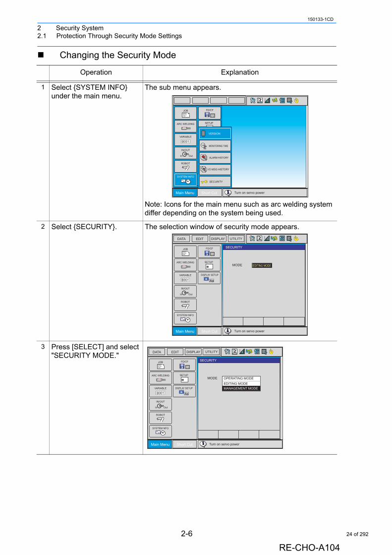
Changing the Security Mode
Operation Explanation
1 Select {SYSTEM INFO} under the main menu.
The sub menu appears.
Note: Icons for the main menu such as arc welding system differ depending on the system being used.
2 Select {SECURITY}. The selection window of security mode appears.
3 Press [SELECT] and select "SECURITY MODE."
Main Menu Short Cut
JOBDOUTMOVEEND
IN/OUT
In Out
SYSTEM INFO
ARC WELDING
VARIABLE
B001
ROBOT
CF
FD/CF
Turn on servo power
SETUP
MONITORING TIME
ALARM HISTORY
I/O MSG HISTORY
VERSION
SECURITY
T
Main Menu Short Cut
JOBDOUTMOVEEND
IN/OUT
In Out
SYSTEM INFO
ARC WELDING
VARIABLE
B001
ROBOT
CF
FD/CF
Turn on servo power
SETUP
SECURITY
MODE EDITING MODE
TDATA EDIT DISPLAY UTILITY
DISPLAY SETUP
Aa
Main Menu Short Cut
JOBDOUTMOVEEND
IN/OUT
In Out
SYSTEM NFO
ARC WELDING
VARIABLE
B001
ROBOT
CF
FD/CF
Turn on servo power
SETUP
SECURITY
MODE
TDATA EDIT DISPLAY UTILITY
DISPLAY SETUP
Aa
OPERATING MODEEDITING MODEMANAGEMENT MODE
2-6
RE-CHO-A104
24 of 292
2 Security System2.1 Protection Through Security Mode Settings
150133-1CD
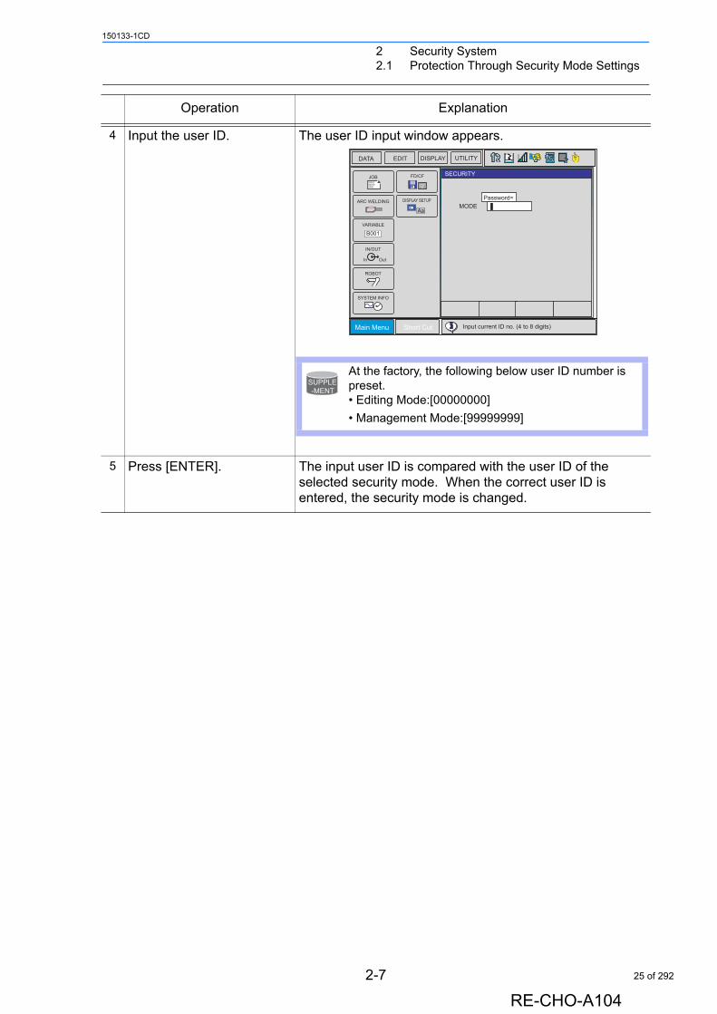
4 Input the user ID. The user ID input window appears.
5 Press [ENTER]. The input user ID is compared with the user ID of the selected security mode. When the correct user ID is entered, the security mode is changed.
Operation Explanation
Main Menu Short Cut
JOBDOUTMOVEEND
IN/OUT
In Out
SYSTEM INFO
ARC WELDING
VARIABLE
B001
ROBOT
CF
FD/CF
Input current ID no. (4 to 8 digits)
SECURITY
MODE
TDATA EDIT DISPLAY UTILITY
DISPLAY SETUP
Aa
Password=
At the factory, the following below user ID number is preset.• Editing Mode:[00000000]
• Management Mode:[99999999]
SUPPLE-MENT
2-7
RE-CHO-A104
25 of 292
2 Security System2.1 Protection Through Security Mode Settings
150133-1CD
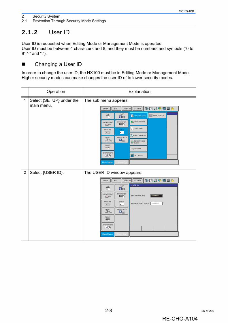
2.1.2 User ID
User ID is requested when Editing Mode or Management Mode is operated.User ID must be between 4 characters and 8, and they must be numbers and symbols (“0 to 9”,“-” and “.”).
Changing a User ID
In order to change the user ID, the NX100 must be in Editing Mode or Management Mode. Higher security modes can make changes the user ID of to lower security modes.
Operation Explanation
1 Select {SETUP} under the main menu.
The sub menu appears.
2 Select {USER ID}. The USER ID window appears.
Main Menu Short Cut
JOBDOUTMOVEEND
IN/OUT
In Out
SYSTEM INFO
ARC WELDING
VARIABLE
B001
ROBOT
CF
FD/CF
SETUP
PARAMETER
DISPLAY SETUP
Aa
TEACHING COND KEY ALLOCATION
OPERATE COND
DATE/TIME
GRP COMBINATION
RESERVE JOBNAME
USER ID
SET SPEED
DATA EDIT DISPLAY UTILITY T
***
Main Menu Short Cut
JOBDOUTMOVEEND
IN/OUT
In Out
SYSTEM INFO
ARC WELDING
VARIABLE
B001
ROBOT
CF
FD/CF
SETUP
PARAMETER
DISPLAY SETUP
Aa
DATA EDIT DISPLAY UTILITY T
EDITING MODE ********
MANAGEMENT MODE ********
USER ID
2-8
RE-CHO-A104
26 of 292
2 Security System2.1 Protection Through Security Mode Settings
150133-1CD
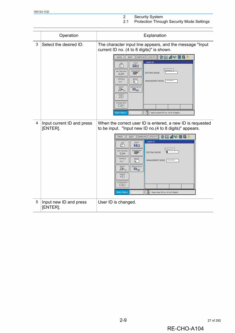
3 Select the desired ID. The character input line appears, and the message "Input current ID no. (4 to 8 digits)" is shown.
4 Input current ID and press [ENTER].
When the correct user ID is entered, a new ID is requested to be input. "Input new ID no.(4 to 8 digits)" appears.
5 Input new ID and press [ENTER].
User ID is changed.
Operation Explanation
Main Menu Short Cut
JOBDOUTMOVEEND
IN/OUT
In Out
SYSTEM INFO
ARC WELDING
VARIABLE
B001
ROBOT
CF
FD/CF
SETUP
PARAMETER
DISPLAY SETUP
Aa
DATA EDIT DISPLAY UTILITY T
EDITING MODE
MANAGEMENT MODE ********
Input current ID no. (4 to 8 digits)
Password=
USER ID
Main Menu Short Cut
JOBDOUTMOVEEND
IN/OUT
In Out
SYSTEM INFO
ARC WELDING
VARIABLE
B001
ROBOT
CF
FD/CF
SETUP
PARAMETER
DISPLAY SETUP
Aa
DATA EDIT DISPLAY UTILITY T
EDITING MODE
MANAGEMENT MODE ********
Input new ID no. (4 to 8 digits)
Password=
USER ID
2-9
RE-CHO-A104
27 of 292
3 Inspections3.1 Regular Inspections
150133-1CD
3 Inspections
3.1 Regular Inspections
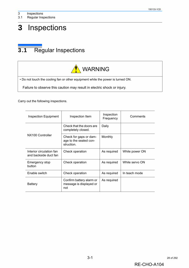
Carry out the following inspections.
• Do not touch the cooling fan or other equipment while the power is turned ON.
Failure to observe this caution may result in electric shock or injury.
Inspection Equipment Inspection ItemInspection Frequency
Comments
NX100 Controller
Check that the doors are completely closed.
Daily
Check for gaps or dam-age to the sealed con-struction.
Monthly
Interior circulation fan and backside duct fan
Check operation As required While power ON
Emergency stopbutton
Check operation As required While servo ON
Enable switch Check operation As required In teach mode
BatteryConfirm battery alarm or message is displayed or not
As required
3-1
RE-CHO-A104
28 of 292
3 Inspections3.2 NX100 Inspections
150133-1CD
3.2 NX100 Inspections
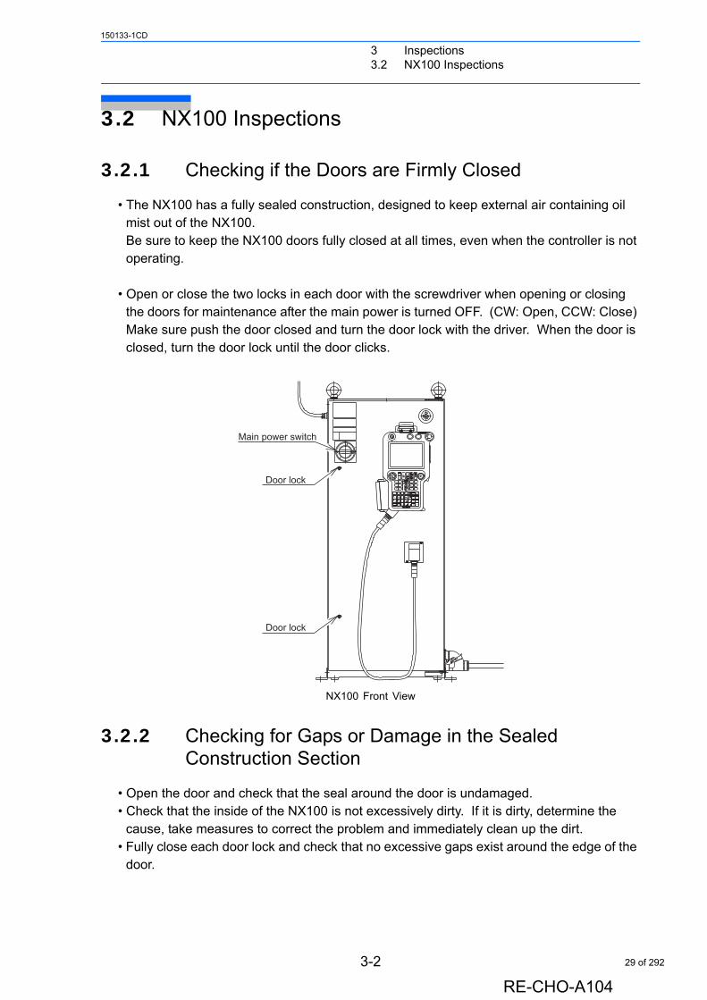
3.2.1 Checking if the Doors are Firmly Closed
• The NX100 has a fully sealed construction, designed to keep external air containing oil mist out of the NX100.Be sure to keep the NX100 doors fully closed at all times, even when the controller is not operating.
• Open or close the two locks in each door with the screwdriver when opening or closing the doors for maintenance after the main power is turned OFF. (CW: Open, CCW: Close) Make sure push the door closed and turn the door lock with the driver. When the door is closed, turn the door lock until the door clicks.
NX100 Front View
3.2.2 Checking for Gaps or Damage in the Sealed Construction Section
• Open the door and check that the seal around the door is undamaged.• Check that the inside of the NX100 is not excessively dirty. If it is dirty, determine the
cause, take measures to correct the problem and immediately clean up the dirt.• Fully close each door lock and check that no excessive gaps exist around the edge of the
door.
Main power switch
Door lock
Door lock
3-2
RE-CHO-A104
29 of 292
3 Inspections3.3 Cooling Fan Inspections
150133-1CD
3.3 Cooling Fan Inspections
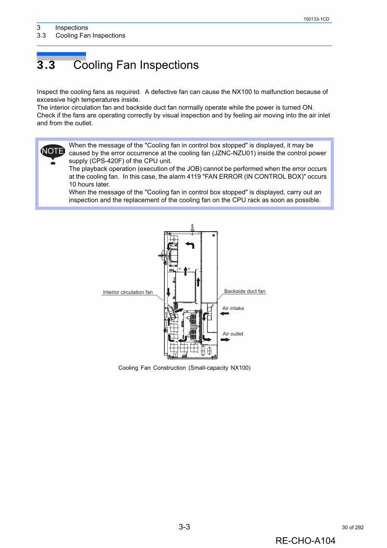
Inspect the cooling fans as required. A defective fan can cause the NX100 to malfunction because of excessive high temperatures inside.The interior circulation fan and backside duct fan normally operate while the power is turned ON. Check if the fans are operating correctly by visual inspection and by feeling air moving into the air inlet and from the outlet.
Cooling Fan Construction (Small-capacity NX100)
When the message of the "Cooling fan in control box stopped" is displayed, it may be caused by the error occurrence at the cooling fan (JZNC-NZU01) inside the control power supply (CPS-420F) of the CPU unit.The playback operation (execution of the JOB) cannot be performed when the error occurs at the cooling fan. In this case, the alarm 4119 "FAN ERROR (IN CONTROL BOX)" occurs 10 hours later.When the message of the "Cooling fan in control box stopped" is displayed, carry out an inspection and the replacement of the cooling fan on the CPU rack as soon as possible.
NOTE
Air intake
Air outlet
Backside duct fanInterior circulation fan
3-3
RE-CHO-A104
30 of 292
3 Inspections3.3 Cooling Fan Inspections
150133-1CD
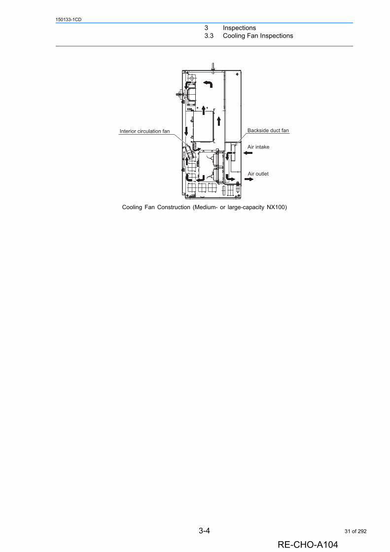
Cooling Fan Construction (Medium- or large-capacity NX100)
Air intake
Backside duct fan
Air outlet
Interior circulation fan
3-4
RE-CHO-A104
31 of 292
3 Inspections3.4 Emergency Stop Button Inspections
150133-1CD
3.4 Emergency Stop Button Inspections
The emergency stop buttons are located on both the front door of the NX100 and the programming pendant. Confirm the servo power is OFF by pressing the emergency stop button on the front door of the NX100 after the servo ON, before the manipulator is operated.
3.5 Enable Switch Inspections
The programing pendant is equipped with a three-position enable switch. Perform the following operation to confirm the enable switch operates.
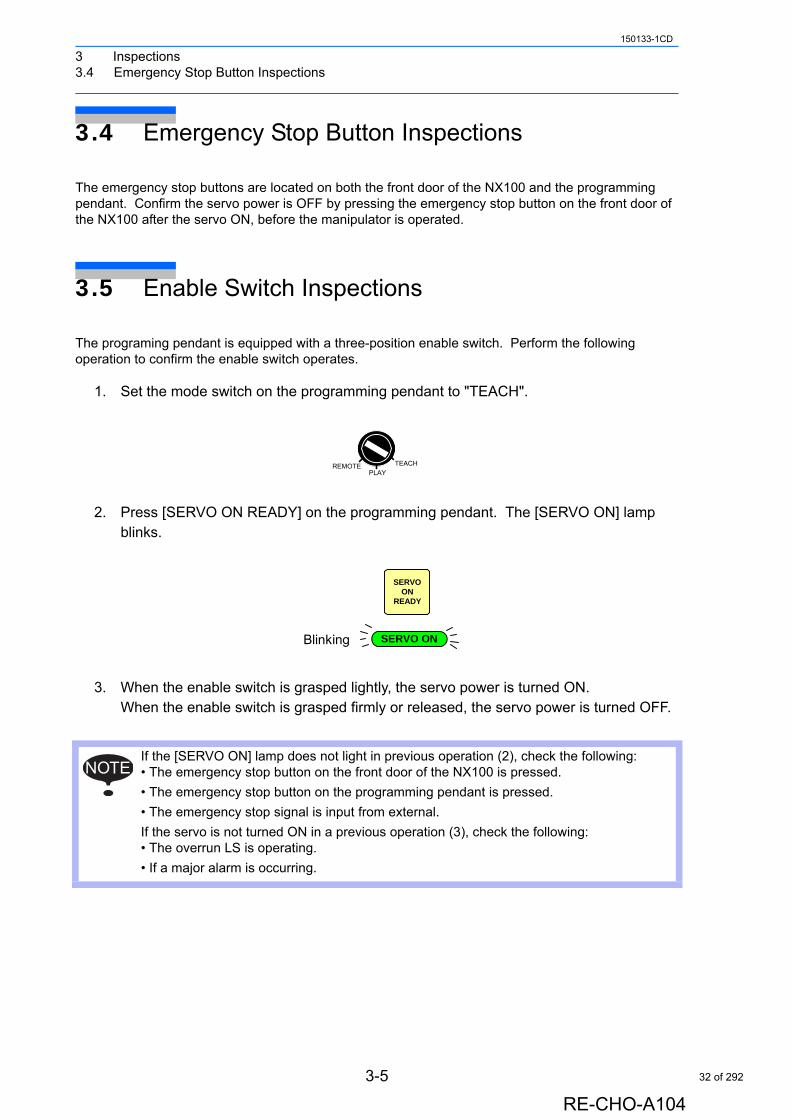
1. Set the mode switch on the programming pendant to "TEACH".
2. Press [SERVO ON READY] on the programming pendant. The [SERVO ON] lamp blinks.
3. When the enable switch is grasped lightly, the servo power is turned ON.When the enable switch is grasped firmly or released, the servo power is turned OFF.
If the [SERVO ON] lamp does not light in previous operation (2), check the following:• The emergency stop button on the front door of the NX100 is pressed.
• The emergency stop button on the programming pendant is pressed.
• The emergency stop signal is input from external.
If the servo is not turned ON in a previous operation (3), check the following:• The overrun LS is operating.
• If a major alarm is occurring.
REMOTE TEACH
PLAY
SERVOON
READY
SERVO ONBlinking
NOTE
3-5
RE-CHO-A104
32 of 292

3 Inspections3.6 Battery Inspections
150133-1CD
3.6 Battery Inspections
The NX100 has a battery that backs up the important program files for user data in the CMOS memory.A battery alarm indicates when a battery has expired and must be replaced. The programming pendant display and the message "Memory battery weak" appears at the bottom of the display.The way to replace the battery is described in “5.1.1 Replacing Parts of the CPU Unit”.
3.7 Power Supply Voltage Confirmation
Check the voltage of 1, 3, 5 terminal of the circuit breaker (QF1) with an electric tester.
Circuit Breaker (QF1)
Power Supply Voltage Confirmation
Measuring Items Terminals Correct Value
Correlate voltage Between 1 and 3, 3 and 5, 5 and 1
200 to 220V (+10%, -15%)
Voltage between earth(phase-S ground)
Between 1 and E, 5 and E
200 to 220V (+10%, -15%)
Between 3 and E About 0V
531
E
Breaker
3-6
RE-CHO-A104
33 of 292

3 Inspections3.8 Open Phase Check
150133-1CD
3.8 Open Phase Check
Open Phase Check List
Check Item Contents
Lead Cable Check Confirm if the lead cable for the power supply is wired as shown in the following. If the wiring is wrong or broken, repair it.
Input Power Supply Check
Check the open phase voltage of input power supply with an electric tester.(Normal value: 200-220VAC (+10%, -15%))
Circuit Breaker (QF1) Check
Turn ON the breaker and check the open phase voltage of “2, 4, 6” of the circuit breaker (QF1) with an electric tester. If abnormal, replace the circuit breaker (QF1).
TR
200/220VAC input
S
Converter
1
2
3
CNP1(2KM)Contactor
2
3
12
4
6
1 2
43
5 6
1X(1KM)
6
5
(QF1)Breaker
1
2
3
1
3
5
4X
Power supply contactor unit
Contactor2 4
31
3-7
RE-CHO-A104
34 of 292
4 Preparation before Replacing Parts150133-1CD
4 Preparation before Replacing Parts
• Before operating the manipulator, check that the SERVO ON lamp turns OFF when the emergency stop buttons on the front door of the NX100 and the programming pendant are pressed.
Injury or damage to machinery may result if the manipulator cannot be stopped in case of an emergency.
• Observe the following precautions when performing teaching operations within the P-point maximum envelope of the manipulator:
- Be sure to use a lockout device to the safeguarding when going inside. Also, display the sign that the operation is being performed inside the safeguarding and make sure no one closes the safeguarding.- View the manipulator from the front whenever possible.- Always follow the predetermined operating procedure.- Ensure that you have a safe place to retreat in case of emergency.
Improper or unintended manipulator operation may result in injury.
• Confirm that no persons are present in the P-point maximum envelope of the manipulator and that you are in a safe location before:
- Turning ON the NX100 power.- Moving the manipulator with the programming pendant
Injury may result if anyone enters the P-point maximum envelope of the manipulator during operation.
• Always press the emergency stop button immediately if there are problems.
Emergency stop buttons are located at the upper right corner of the front door of the NX100 and on the upper right of the programming pendant.
4-1
RE-CHO-A104
35 of 292
4 Preparation before Replacing Parts
150133-1CD
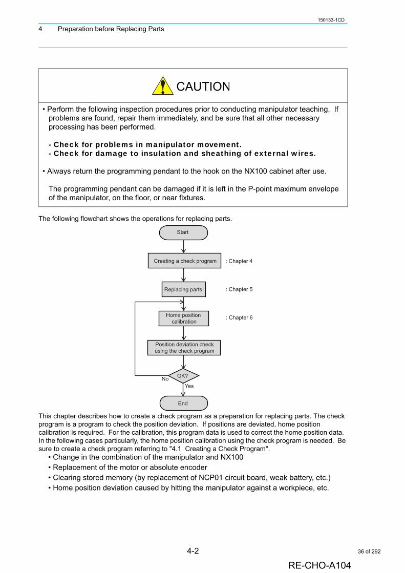
The following flowchart shows the operations for replacing parts.
This chapter describes how to create a check program as a preparation for replacing parts. The check program is a program to check the position deviation. If positions are deviated, home position calibration is required. For the calibration, this program data is used to correct the home position data. In the following cases particularly, the home position calibration using the check program is needed. Be sure to create a check program referring to "4.1 Creating a Check Program".
• Change in the combination of the manipulator and NX100• Replacement of the motor or absolute encoder• Clearing stored memory (by replacement of NCP01 circuit board, weak battery, etc.)• Home position deviation caused by hitting the manipulator against a workpiece, etc.
• Perform the following inspection procedures prior to conducting manipulator teaching. If problems are found, repair them immediately, and be sure that all other necessary processing has been performed.
- Check for problems in manipulator movement.- Check for damage to insulation and sheathing of external wires.
• Always return the programming pendant to the hook on the NX100 cabinet after use.
The programming pendant can be damaged if it is left in the P-point maximum envelope of the manipulator, on the floor, or near fixtures.
Start
Creating a check program
Position deviation checkusing the check program
Replacing parts
Home position calibration
OK?
End
: Chapter 4
: Chapter 5
: Chapter 6
YesNo
4-2
RE-CHO-A104
36 of 292
4 Preparation before Replacing Parts4.1 Creating a Check Program
150133-1CD
4.1 Creating a Check Program
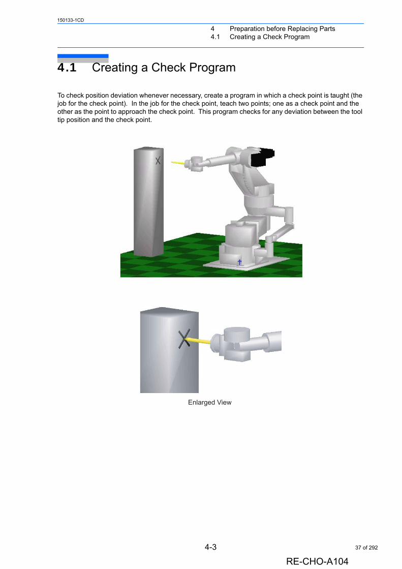
To check position deviation whenever necessary, create a program in which a check point is taught (the job for the check point). In the job for the check point, teach two points; one as a check point and the other as the point to approach the check point. This program checks for any deviation between the tool tip position and the check point.
Enlarged View
4-3
RE-CHO-A104
37 of 292
5 Replacing Parts5.1 Replacing NX100 Parts
150133-1CD
5 Replacing Parts
5.1 Replacing NX100 Parts
• Turn OFF the power supply before opening the NX100 doors.
Failure to observe this warning may result in electric shock.
• After turning OFF the power supply, wait at least 5 minutes before replacing a SREVOPACK (including the converter) or control power supply. Do not touch any terminals during this period.
Failure to observe this warning may result in electric shock.
• To prevent anyone inadvertently turning ON the power supply during maintenance, put up a warning sign such as "DO NOT TURN ON THE POWER" at the primary power supply (knife switch, wiring circuit breaker, etc.) and at the NX100 and related controllers and use accepted lockout/tagout procedures.
Failure to observe this caution may result in electric shock or injury.
• Do not touch the regeneration resistors. They are very hot.
Failure to observe this caution may result in burn injuries.
• After maintenance is completed, carefully check that no tools are left inside the NX100 and that the doors are securely closed.
Failure to observe this caution may result in electric shock or injury.
5-1
RE-CHO-A104
38 of 292
5 Replacing Parts5.1 Replacing NX100 Parts
150133-1CD
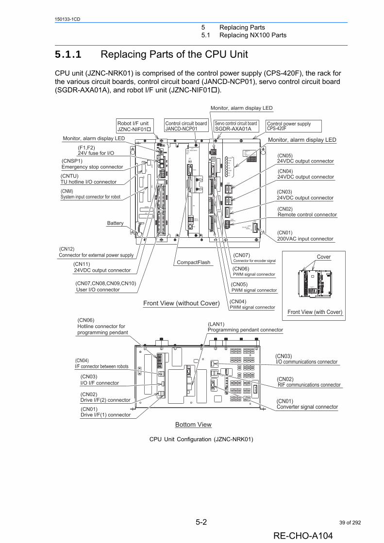
5.1.1 Replacing Parts of the CPU Unit
CPU unit (JZNC-NRK01) is comprised of the control power supply (CPS-420F), the rack for the various circuit boards, control circuit board (JANCD-NCP01), servo control circuit board (SGDR-AXA01A), and robot I/F unit (JZNC-NIF01).
CPU Unit Configuration (JZNC-NRK01)
KJHVUT
282930
080910181920
GFEDCSRQPN
Co.,Ltd.
23242526
0304050613141516
JAPAN
27
0717
BAML
DATEFuji
21
0111
No.
POWERCPS-NX1
Electric
0212
SUPPLY
+5VSB
+5V
+24V
OTHER
FAN
PON
CN05(+24V1)
CN04(+24V2)
OHT
SOURCE
CN01(AC IN)
INPUT
3A50/60Hz
200-240V AC
(TU)CN03
(REMOTE)CN02
Control power supplyServo control circuit board
Monitor, alarm display LED
SGDR-AXA01A CPS-420F
24VDC output connector
Monitor, alarm display LED
(CN05)
24VDC output connector
200VAC input connector
(CN02)Remote control connector
(CN01)
(CN03)
(CN04)
Cover(CN07)
(CN06)Connector for encoder signal
(CN05)PWM signal connector
PWM signal connector
(CN04)PWM signal connector
Front View (with Cover)
Control circuit board
CPU
DATE
0
REV
1
TYPE JANCD-NCP01
LED
CNSP1
JANCD-NCP01
Monitor, alarm display LED
(F1,F2)
(CNSP1)Emergency stop connector
24V fuse for I/O
JZNC-NIF01Robot I/F unit
VIDEO
IDE
CNRI
CNTU
CNM
CNRO
CNFAN
PS2
USB1(L)USB1(R)CNBAT
ATX
(CNTU)
(CNM)
TU hotline I/O connector
System input connector for robot
Battery
(CN12)
User I/O connector
24VDC output connector
Connector for external power supply
(CN11)
(CN07,CN08,CN09,CN10)
CompactFlash
Front View (without Cover)
I/O communications connector
RIF communications connector
(CN03)
(CN02)
Converter signal connector(CN01)
(CN06)Hotline connector for programming pendant
(CN03)
(CN02)
I/O I/F connector
I/F connector between robots(CN04)
Bottom View
(CN01)Drive I/F(1) connector
Drive I/F(2) connector
Programming pendant connector(LAN1)
24VDC output connector
5-2
RE-CHO-A104
39 of 292
5 Replacing Parts5.1 Replacing NX100 Parts
150133-1CD
Replacing the Battery
Replace the battery immediately if a battery alarm occurs. Replace the battery within two hours after the breaker turns OFF.(The battery alarms appear on the programing pendant display.)
Replacement Procedure
1. Remove the left cover of the CPU unit.2. Remove the battery connector (BAT) on the back board on the left of the CPU unit.3. Remove the battery from the rack frame.4. Mount a new battery on the rack frame and connect the battery connector (BAT) on the
back board.
Replacing the Control Circuit Board (JANCD-NCP01)
Turn OFF the power before replacing a circuit board.
Replacement Procedure
1. Disconnect all cables connected to the circuit board. (Be sure to remove the connec-tors at the bottom of the circuit board.)
2. Remove 2 screws fixing the circuit board and rack.3. Pull out the circuit board from the rack.4. Remove the CompactFlash from the removed circuit board and insert the Compact-
Flash into a new circuit board.5. Mount the new circuit board to the rack. 6. Tighten upper and lower screws.
Although the CMOS memory is backed up by super capacitor, the battery must be replaced as soon as the battery alarm occurs. The job data and other data may be lost if the battery alarm occurs and the breaker is turned OFF for more than two hours.
The JANCD-NCP01 circuit board contains important file data for the user programs, which is backed up by the battery. Incorrect operations can cause this stored file data to be lost.
NOTE
NOTE
5-3
RE-CHO-A104
40 of 292
5 Replacing Parts5.1 Replacing NX100 Parts
150133-1CD
7. Connect all disconnected cables.
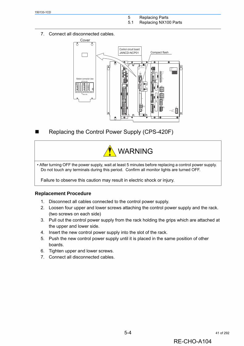
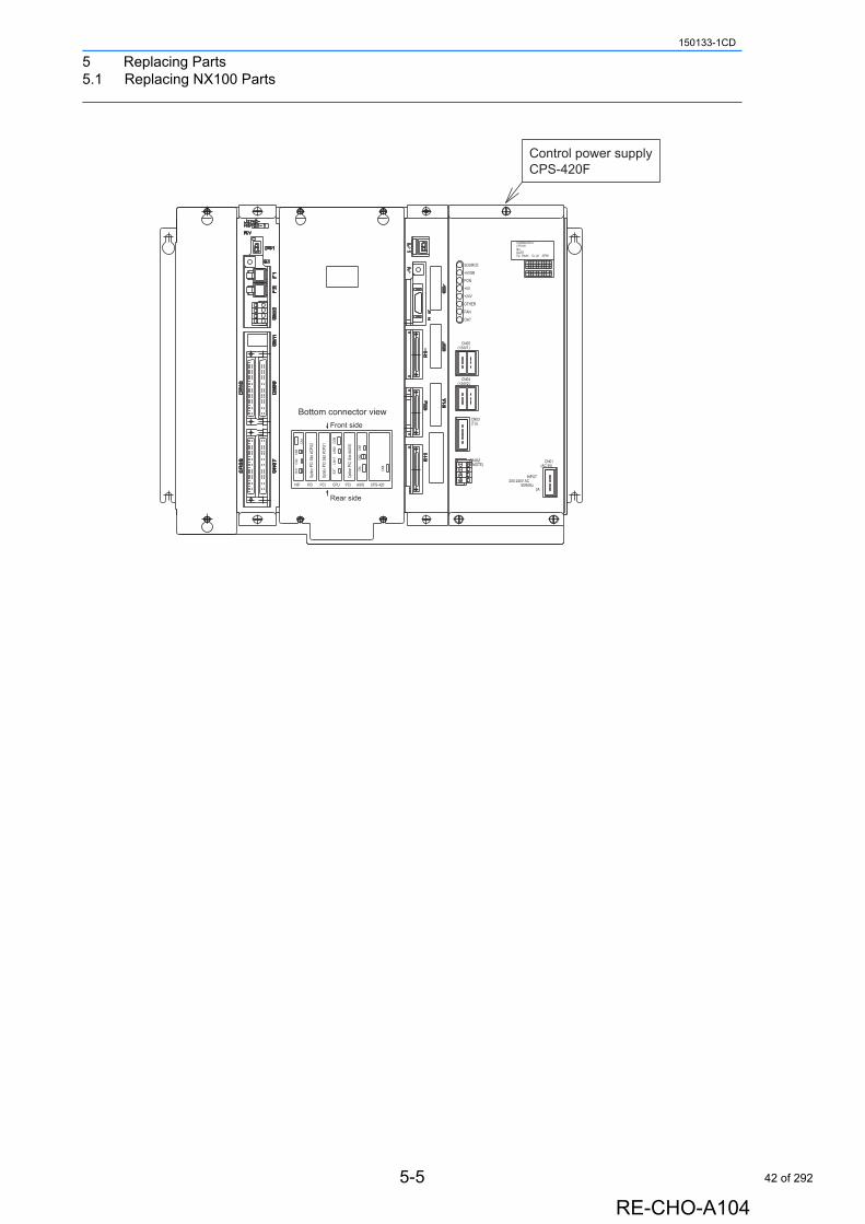
Replacing the Control Power Supply (CPS-420F)
Replacement Procedure
1. Disconnect all cables connected to the control power supply.2. Loosen four upper and lower screws attaching the control power supply and the rack.
(two screws on each side)3. Pull out the control power supply from the rack holding the grips which are attached at
the upper and lower side.4. Insert the new control power supply into the slot of the rack.5. Push the new control power supply until it is placed in the same position of other
boards.6. Tighten upper and lower screws.7. Connect all disconnected cables.
• After turning OFF the power supply, wait at least 5 minutes before replacing a control power supply. Do not touch any terminals during this period. Confirm all monitor lights are turned OFF.
Failure to observe this caution may result in electric shock or injury.
KJHVUT
28 29 30
08 09 1018 19 20
GFEDCSRQPN
Co.,Ltd.
23 24 25 26
03 04 05 0613 14 15 16
JAPAN
27
0717
BAML
DATEFuji
21
0111
No.
POWERCPS-NX1
Electric
22
0212
SUPPLY
LAN0
COM
Front side
CN3
CN1
Bottom connector view
CPS-420CN
6
LAN1
CPUPCI PCI
EXT CN
1
AXIS
CN2
CN2
CN1
PCINIF
Rear side
CN3
Optio
n PC
I Slot
#CP
U2
Optio
n PC
I Slot
#CP
U1
Optio
n PC
I Slot
#AX
IS
+5VSB
+5V
+24V
OTHER
FAN
PON
CN05(+24V1)
CN04(+24V2)
OHT
SOURCE
CN01(AC IN)
INPUT
3A50/60Hz
200-240V AC
(TU)CN03
(REMOTE)CN02
Control circuit board
VIDEO
CPUTYPE JANCD-NCP01DATE
1LED0
REV
JANCD-NCP01
Cover
USB1(L)USB1(R)
IDE
PS2
Compact flash
5-4
RE-CHO-A104
41 of 292
5 Replacing Parts5.1 Replacing NX100 Parts
150133-1CD
KJHVUT
28 29 30
08 09 1018 19 20
GFEDCSRQPN
Co.,Ltd.
23 24 25 26
03 04 05 0613 14 15 16
JAPAN
27
0717
BAML
DATEFuji
21
0111
No.
POWERCPS-NX1
Electric
22
0212
SUPPLY
LAN0
COM
Front side
CN3
CN1
Bottom connector view
CPS-420
CN6
LAN1
CPUPCI PCI
EXT CN
1
AXIS
CN2
CN2
CN1
PCINIF
Rear side
CN3
Optio
n PC
I Slot
#CP
U2
Optio
n PC
I Slot
#CP
U1
Optio
n PC
I Slot
#AX
IS
+5VSB
+5V
+24V
OTHER
FAN
PON
CN05(+24V1)
CN04(+24V2)
OHT
SOURCE
CN01(AC IN)
INPUT
3A50/60Hz
200-240V AC
(TU)CN03
(REMOTE)CN02
CPS-420FControl power supply
5-5
RE-CHO-A104
42 of 292
5 Replacing Parts5.1 Replacing NX100 Parts
150133-1CD
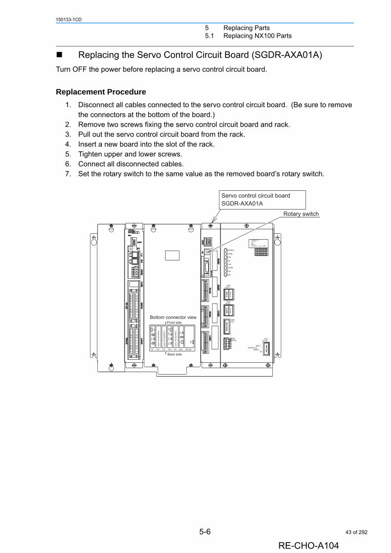
Replacing the Servo Control Circuit Board (SGDR-AXA01A)
Turn OFF the power before replacing a servo control circuit board.
Replacement Procedure
1. Disconnect all cables connected to the servo control circuit board. (Be sure to remove the connectors at the bottom of the board.)
2. Remove two screws fixing the servo control circuit board and rack.3. Pull out the servo control circuit board from the rack.4. Insert a new board into the slot of the rack.5. Tighten upper and lower screws.6. Connect all disconnected cables.7. Set the rotary switch to the same value as the removed board’s rotary switch.
KJHVUT
28 29 30
08 09 1018 19 20
GFEDCSRQPN
Co.,Ltd.
23 24 25 26
03 04 05 0613 14 15 16
JAPAN
27
0717
BAML
DATEFuji
21
0111
No.
POWERCPS-NX1
Electric
22
0212
SUPPLY
LAN0
COM
Front side
CN3
CN1
Bottom connector view
CPS-420
CN6
LAN1
CPUPCI PCI
EXT CN
1
AXIS
CN2
CN2
CN1
PCINIF
Back side
CN3
Optio
n PC
I Slot
#CP
U2
Optio
n PC
I Slot
#CP
U1
Optio
n PC
I Slot
#AX
IS
+5VSB
+5V
+24V
OTHER
FAN
PON
CN05(+24V1)
CN04(+24V2)
OHT
SOURCE
CN01(AC IN)
INPUT
3A50/60Hz
200-240V AC
(TU)CN03
(REMOTE)CN02
Rotary switch
Servo control circuit boardSGDR-AXA01A
5-6
RE-CHO-A104
43 of 292
5 Replacing Parts5.1 Replacing NX100 Parts
150133-1CD
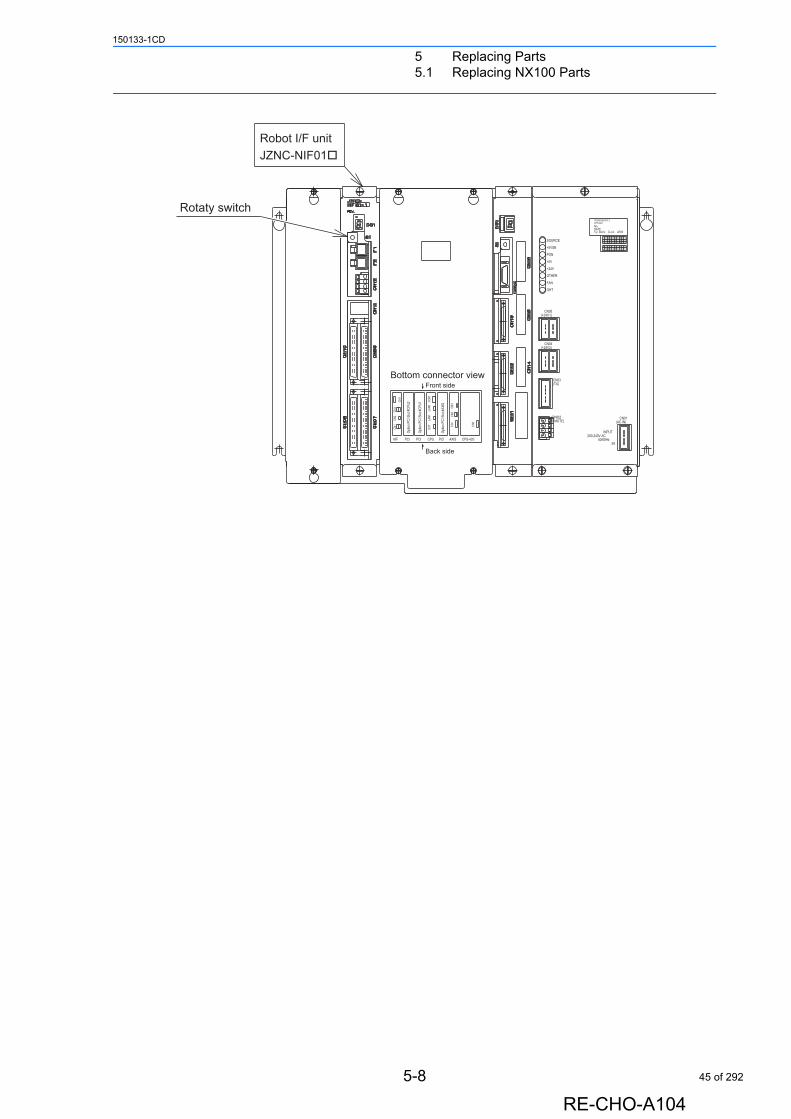
Replacing the Robot I/F Unit (JZNC-NIF01)
Replacement Procedure
1. Back up the robot data.1) Insert a CF card for backup to the programming pendant, and start the system in
maintenance mode.2) Select {TOOL} {CompactFlash} "CMOS SAVE" to save the CMOS data.
2. Turn OFF the power after making backup.3. Disconnect all cables on the I/F unit.4. Remove two screws fixing the robot I/F unit and rack.5. Pull out the robot I/F unit from the rack.6. Insert new robot I/F unit into the slot of the rack.7. Tighten upper and lower screws of the robot I/F unit.8. Connect all cables disconnected in the procedure 3.9. Set the rotary switch as the same value as the original I/F unit.10. Start the system in maintenance mode and load the backup data.
1) Turn ON the power with pressing the [MAIN MENU] key.2) Change the security to management mode and select {TOOL} {Compact-
Flash} "CMOS LOAD"
• Turn OFF the power before replacing the robot I/F unit (JZNC-NIF01).
• Be sure to back up robot data before replacing the robot I/F unit since the robot I/F unit
contains important data such as robot jobs and parameters.
• There are some versions which require maker mode operations after replacing the robot
I/F unit. Contact your Yaskawa representative for maker mode operations.
• Before removing the robot I/F unit from the CPU rack temporarily, turn ON the system
power and charge the onboard capacitor for one hour. The CMOS data on the robot I/F
unit are kept temporarily by the onboard capacitor power. The capacitor is fully charged
in one hour, and discharged in 16 hours when the I/F unit is removed from the CPU rack.
If the capacitor is discharged, the CMOS data will be cleared and all the system settings
and user settings will be lost.
For under NS1.8HA-00 versions, save all individual data in online mode.However, for all versions, all individual data must be saved for safe.
• For under the versions: NS3.10-00, NS2.30-02, NT2.40-02, NS2.0P-00,
NS2.0P-12, and NJ3.20-00, initialize the system in maker mode before
loading the CMOS data.
• For under NS1.8HA-00 versions, start the system in online mode after
loading the CMOS data, and load all the individual data EXCEPT jobs and
parameters.
NOTE
SUPPLE-MENT
SUPPLE-MENT
5-7
RE-CHO-A104
44 of 292
5 Replacing Parts5.1 Replacing NX100 Parts
150133-1CD
KJHVUT
28 29 30
08 09 1018 19 20
GFEDCSRQPN
Co.,Ltd.
23 24 25 26
03 04 05 0613 14 15 16
JAPAN
27
0717
BAML
DATEFuji
21
0111
No.
POWERCPS-NX1
Electric
22
0212
SUPPLY
LAN0
COM
Front side
CN3
CN1
Bottom connector view
CPS-420
CN6
LAN1
CPUPCI PCI
EXT CN
1
AXIS
CN2
CN2
CN1
PCINIF
Back side
CN3
Optio
n PC
I Slot
#CP
U2
Optio
n PC
I Slot
#CP
U1
Optio
n PC
I Slot
#AX
IS
+5VSB
+5V
+24V
OTHER
FAN
PON
CN05(+24V1)
CN04(+24V2)
OHT
SOURCE
CN01(AC IN)
INPUT
3A50/60Hz
200-240V AC
(TU)CN03
(REMOTE)CN02
Rotaty switch
Robot I/F unitJZNC-NIF01
5-8
RE-CHO-A104
45 of 292
5 Replacing Parts5.1 Replacing NX100 Parts
150133-1CD
Replacing the Robot I/F Circuit Board (JANCD-NIF01)
Replacement Procedure1. Follow the replacement steps 1 to 5 of " Replacing the Robot I/F Unit (JZNC-NIF01) "
to remove the robot I/F unit from the CPU rack.2. Remove five screws fixing the I/O circuit board (JANCD-NIO01) and the robot I/F cir-
cuit board (JANCD-NIF01).3. Disconnect the I/O circuit board and the robot I/F circuit board with due care.4. Remove five studs fixing the robot I/F circuit board (JANCD-NIF01) on the base plate.5. Fix new robot I/F circuit board (JANCD-NIF01) with five studs on the base plate.6. Connect the I/O circuit board (JANCD-NIO01) to the new robot I/F circuit board
(JANCD-NIF01) with the onboard connector.7. Tighten five screws to fix the I/O circuit board (JANCD-NIO01) and the robot I/F cir-
cuit board (JANCD-NIF01).8. Insert the robot I/F unit into the slot of the CPU rack.9. Tighten upper and lower screws of the robot I/F unit.10. Connect all cables disconnected in the procedure 1.11. Set the rotary switch as the same value as the removed board.12. Start the system in maintenance mode and load the backup data.
1) Turn ON the power with pressing the [MAIN MENU] key.2) Change the security to management mode and select {TOOL} {Compact-
Flash} "CMOS LOAD"
• Turn OFF the power before replacing the robot I/F circuit board (JANCD-NIF01).
• Be sure to back up robot data before replacing the robot I/F unit since the robot I/F unit
contains important data such as robot jobs and parameters.
• There are some versions which require maker mode operations after replacing the robot
I/F circuit board.
Contact your Yaskawa representative for maker mode operations.
• Before removing the robot I/F unit from the CPU rack temporarily, turn ON the system
power and charge the onboard capacitor for one hour. The CMOS data on the robot I/F
unit are kept temporarily by the onboard capacitor power. The capacitor is fully charged
in one hour, and discharged in 16 hours when the I/F unit is removed from the CPU rack.
If the capacitor is discharged, the CMOS data will be cleared and all the system settings
and user settings will be lost.
Refer to the procedure 10 of " Replacing the Robot I/F Unit (JZNC-NIF01) " to recover
data.
• For under the versions: NS3.10-00, NS2.30-02, NT2.40-02, NS2.0P-00,
NS2.0P-12, and NJ3.20-00, initialize the system in maker mode before load-
ing the CMOS data.
• For under NS1.8HA-00 versions, start the system in online mode after load-
ing the CMOS data, and load all the individual data EXCEPT jobs and
parameters.
NOTE
SUPPLE-MENT
5-9
RE-CHO-A104
46 of 292
5 Replacing Parts5.1 Replacing NX100 Parts
150133-1CD
Replacing the I/O Circuit Board (JANCD-NIO01)
Replacement Procedure1. Follow the replacement procedures 1 to 5 of " Replacing the Robot I/F Unit (JZNC-
NIF01) " to remove the robot I/F unit from the CPU rack.2. Remove five screws fixing the I/O circuit board (JANCD-NIO01) and the robot I/F cir-
cuit board (JANCD-NIF01).3. Disconnect the I/O circuit board and the robot I/F circuit board with due care.4. Connect new I/O circuit board (JANCD-NIO01) to the robot I/F circuit board (JANCD-
NIF01) with the onboard connector. 5. Tighten five screws to fix the I/O circuit board (JANCD-NIO01) and the robot I/F cir-
cuit board (JANCD-NIF01).6. Insert the robot I/F unit into the slot of the CPU rack.7. Tighten upper and lower screws of the robot I/F unit.8. Connect all cables disconnected in the procedure 1.
• Turn OFF the power before replacing the I/O circuit board (JANCD-NIO01).
• Be sure to back up robot data before replacing the robot I/F unit since the robot I/F unit
contains important data such as robot jobs and parameters.
• Before removing the robot I/F unit from the CPU rack temporarily, turn ON the system
power and charge the onboard capacitor for one hour. The CMOS data on the robot I/F
unit are kept temporarily by the onboard capacitor power. The capacitor is fully charged
in one hour, and discharged in 16 hours when the I/F unit is removed from the CPU rack.
If the capacitor is discharged, the CMOS data will be cleared and all the system settings
and user settings will be lost.
Refer to the procedure 10 of " Replacing the Robot I/F Unit (JZNC-NIF01) " to recover
data.
NOTE
5-10
RE-CHO-A104
47 of 292
5 Replacing Parts5.1 Replacing NX100 Parts
150133-1CD
5.1.2 Replacing the SERVOPACK
There are two kinds of SERVOPACKs.
Replacement Procedure (Integrated Type)
1. Turn OFF the breaker and the primary power supply and wait at least 5 minutes before replacing. Do not touch any terminals during this period.
2. Verify that the SERVOPACK CHARGE lamp (red LED) is unlit.3. Disconnect all the cables connected externally to the SERVOPACK.
Three-phase AC power supply connector (CNP1)
Regenerative resistor connector (CNP3)
AC control power supply connector (CNP11)
DC control power supply connector (CN101)
Converter control signal connector (CN1)
PWM signal connectors (AMP1 to AMP6-CN1)
Motor power connectors (AMP1 to AMP6-CNP6)
4. Remove the ground wiring connected to the SERVOPACK.5. Remove the two screws at the top on each side of the SERVOPACK.6. Hold the top and bottom grips and lift them to pull out the SERVOPACK.7. Install the new SERVOPACK and reconnect the connectors in the reverse order of the
removing procedure.
• After turning OFF the power supply, wait at least 5 minutes before replacing a SERVOPACK. Do not touch any terminals during this period.
Failure to observe this warning may result in electric shock.
Type Manipulator
Integrated Type HP3, HP6, EA1400N
Separated Type HP20, EA1900N, UP20MN, UP50N, ES165N, HP165, ES200N, ES165RN, ES200RN
1
2
3
4
5
6
7
5-11
RE-CHO-A104
48 of 292
5 Replacing Parts5.1 Replacing NX100 Parts
150133-1CD
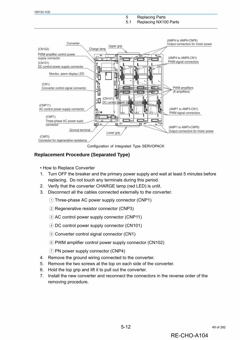
Configuration of Integrated Type SERVOPACK
Replacement Procedure (Separated Type)
• How to Replace Converter1. Turn OFF the breaker and the primary power supply and wait at least 5 minutes before
replacing. Do not touch any terminals during this period.2. Verify that the converter CHARGE lamp (red LED) is unlit.3. Disconnect all the cables connected externally to the converter.
Three-phase AC power supply connector (CNP1)
Regenerative resistor connector (CNP3)
AC control power supply connector (CNP11)
DC control power supply connector (CN101)
Converter control signal connector (CN1)
PWM amplifier control power supply connector (CN102)
PN power supply connector (CNP4)
4. Remove the ground wiring connected to the converter.5. Remove the two screws at the top on each side of the converter.6. Hold the top grip and lift it to pull out the converter.7. Install the new converter and reconnect the connectors in the reverse order of the
removing procedure.
Charge lamp
ConverterUpper grip
(CN1)
(CN101)
Monitor, alarm display LED
DC control power supply connector
Converter control signal connector
(CNP1)Three-phase AC power suply connector
(CNP3)Connector for regenerative resistance
Gronud terminalLower grip
(CNP11)AC control power supply connector
PWM signal connectors(AMP1 to AMP3-CN1)
(AMP1 to AMP3-CNP6)Output connectors for motor power
PWM signal connectors
PWM amplifiers(6 amplifiers)
(AMP4 to AMP6-CNP6)
(AMP4 to AMP6-CN1)
Output connectors for motor power
(CN101)DC control power supply connector
(CN102)PWM amplifier control power supply connector
1
2
3
4
5
6
7
5-12
RE-CHO-A104
49 of 292
5 Replacing Parts5.1 Replacing NX100 Parts
150133-1CD
• How to Replace SERVOPACK1. Turn OFF the breaker and the primary power supply and wait at least 5 minutes before
replacing. Do not touch any terminals during this period.2. Verify that the converter CHARGE lamp (red LED) is unlit.3. Disconnect all the cables connected externally to the SERVOPACK.
PWM signal connectors (AMP1 to AMP6-CN1)
PWM amplifier control power supply connector (CN102) (at converter side)
PN power supply connector (CNP4) (at converter side)
Motor power connectors (AMP1 to AMP6-CNP6)
4. Remove the ground wiring connected to the SERVOPACK.5. Remove the two screws at the top on each side of the SERVOPACK.6. Hold the top and bottom grips and lift them to pull out the SERVOPACK.7. Install the new PWM amplifier and reconnect the connectors in the reverse order of the
removing procedure.
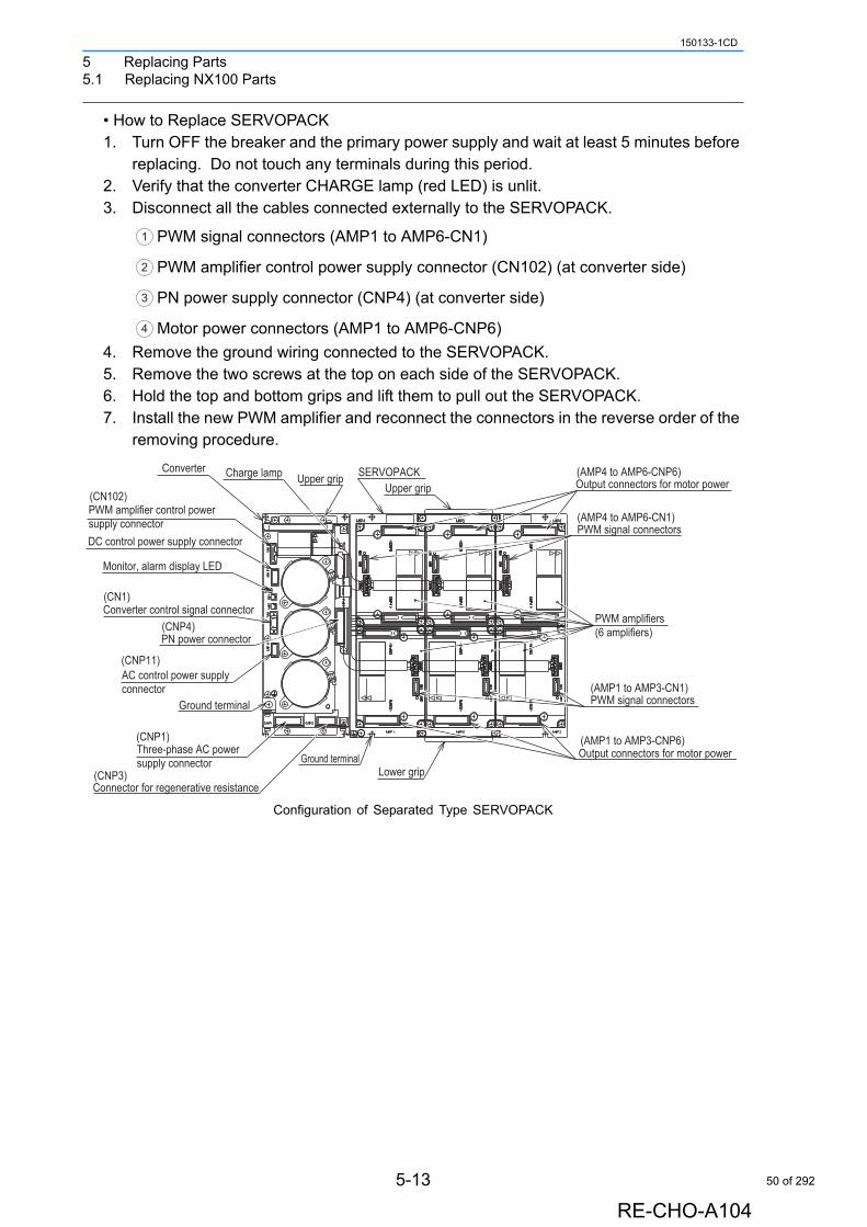
Configuration of Separated Type SERVOPACK
1
2
3
4
(AMP4 to AMP6-CNP6)
(AMP4 to AMP6-CN1)
Output connectors for motor power
PWM amplifiers(6 amplifiers)
PWM signal connectors
PWM signal connectors
Output connectors for motor power(AMP1 to AMP3-CNP6)
(AMP1 to AMP3-CN1)
Upper gripUpper gripCharge lamp
(CNP4)PN power connector
SERVOPACK
(CN102)
(CN1)
PWM amplifier control powersupply connector
Converter
Converter control signal connector
Monitor, alarm display LED
DC control power supply connector
Lower gripGround terminal
Ground terminal
(CNP3)Connector for regenerative resistance
(CNP1)Three-phase AC power supply connector
AC control power supply connector
(CNP11)
5-13
RE-CHO-A104
50 of 292

5 Replacing Parts5.1 Replacing NX100 Parts
150133-1CD
5.1.3 Checking and Replacing Fuses
Power Supply Contactor Unit
The types of fuses on power supply contactor unit (JZRCR-NTUoo) are as follows:
Fuse Position
If a fuse appears to be blown (see "" 8.3 Alarm Message List ""), remove each fuse shown above and check the continuity with an electric tester. If the fuse is blown, replace it with the same type of fuse (supplied).
Parts No. Fuse Name Specification
1FU, 2FU Control Power Supply Fuse 250V,10A, Time Lag Fuse(326010, 250V, 10A (Littelfuse))
3FU Brake Fuse SDP50, 5A, 125V (Daito Communication Apparatus Co., Ltd.)
Determine and correct the cause of the blown fuse. If the problem is uncorrected, the fuse may blow again.
NJ20
96-
DATE
SER
NO.
JAPA
N
TYPE
YASK
AWA
ELE
CTRI
C C
ORPO
RATI
ON
FF
EE
UUFF
EE
SS
UUSS
CN
085A
125V
3FU
CN
06C
N07
CN
05C
N04
2FU10A 250V
1FU10A 250V
4X
CN03
CN02
CN
01S
W1
3X
2X
1X
(1FU) (2FU)
(3FU)Brake fuse
Fuse for AC control power supply
NOTE
5-14
RE-CHO-A104
51 of 292
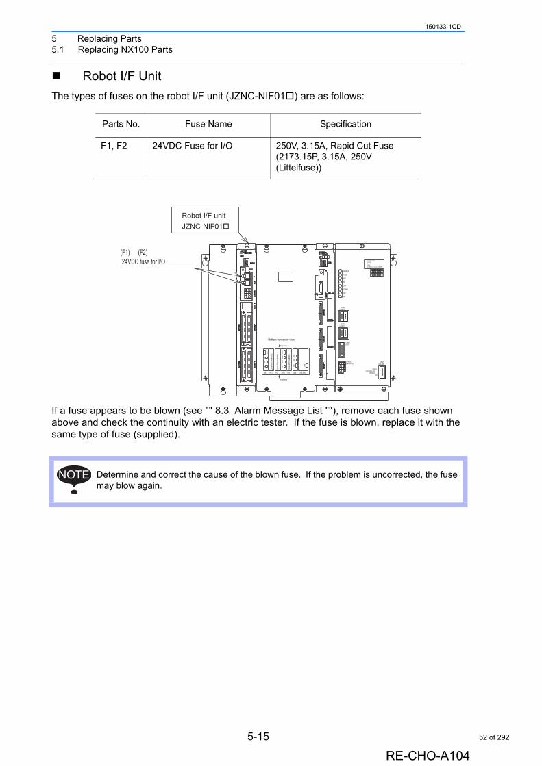
5 Replacing Parts5.1 Replacing NX100 Parts
150133-1CD
Robot I/F Unit
The types of fuses on the robot I/F unit (JZNC-NIF01) are as follows:
If a fuse appears to be blown (see "" 8.3 Alarm Message List ""), remove each fuse shown above and check the continuity with an electric tester. If the fuse is blown, replace it with the same type of fuse (supplied).
Parts No. Fuse Name Specification
F1, F2 24VDC Fuse for I/O 250V, 3.15A, Rapid Cut Fuse(2173.15P, 3.15A, 250V (Littelfuse))
Determine and correct the cause of the blown fuse. If the problem is uncorrected, the fuse may blow again.
LAN0
COM
Front side
CN3
CN1
Bottom connector view
CPS-420
CN6
LAN1
CPUPCI PCI
EXT CN
1
AXIS
CN2
CN2
CN1
PCINIF
Back side
CN3
Optio
n PC
I Slot
#CP
U2
Optio
n PC
I Slot
#CP
U1
Optio
n PC
I Slot
#AX
IS
1707
27
JAPAN
201918100908
302928
SUPPLY
1202
22
Electric
CPS-NX1POWER
No.
1101
21
FujiDATE
1615141306050403
26252423
Co.,Ltd.
SG
T U VH J K
L MA B
N P Q RC D E F
SOURCE
OHT
PON
FAN
OTHER
+24V
+5V
+5VSB
(+24V1)CN05
CN01(AC IN)
CN03
(+24V2)CN04
(TU)
INPUT
CN02(REMOTE)
50/60Hz3A
200-240V AC
(F1) (F2)24VDC fuse for I/O
Robot I/F unitJZNC-NIF01
NOTE
5-15
RE-CHO-A104
52 of 292
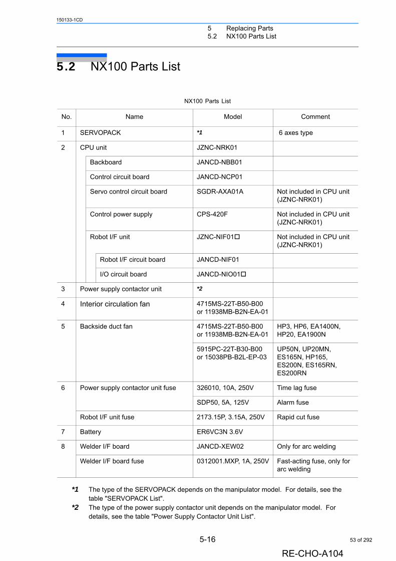
5 Replacing Parts5.2 NX100 Parts List
150133-1CD
5.2 NX100 Parts List
*1 The type of the SERVOPACK depends on the manipulator model. For details, see the table "SERVOPACK List".
*2 The type of the power supply contactor unit depends on the manipulator model. For details, see the table "Power Supply Contactor Unit List".
NX100 Parts List
No. Name Model Comment
1 SERVOPACK *1 6 axes type
2 CPU unit JZNC-NRK01
Backboard JANCD-NBB01
Control circuit board JANCD-NCP01
Servo control circuit board SGDR-AXA01A Not included in CPU unit (JZNC-NRK01)
Control power supply CPS-420F Not included in CPU unit (JZNC-NRK01)
Robot I/F unit JZNC-NIF01 Not included in CPU unit (JZNC-NRK01)
Robot I/F circuit board JANCD-NIF01
I/O circuit board JANCD-NIO01
3 Power supply contactor unit *2
4 Interior circulation fan 4715MS-22T-B50-B00or 11938MB-B2N-EA-01
5 Backside duct fan 4715MS-22T-B50-B00or 11938MB-B2N-EA-01
HP3, HP6, EA1400N, HP20, EA1900N
5915PC-22T-B30-B00or 15038PB-B2L-EP-03
UP50N, UP20MN, ES165N, HP165, ES200N, ES165RN, ES200RN
6 Power supply contactor unit fuse 326010, 10A, 250V Time lag fuse
SDP50, 5A, 125V Alarm fuse
Robot I/F unit fuse 2173.15P, 3.15A, 250V Rapid cut fuse
7 Battery ER6VC3N 3.6V
8 Welder I/F board JANCD-XEW02 Only for arc welding
Welder I/F board fuse 0312001.MXP, 1A, 250V Fast-acting fuse, only for arc welding
5-16
RE-CHO-A104
53 of 292
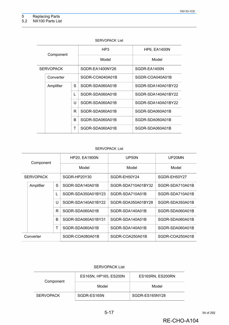
5 Replacing Parts5.2 NX100 Parts List
150133-1CD
SERVOPACK List
ComponentHP3 HP6, EA1400N
Model Model
SERVOPACK SGDR-EA1400NY26 SGDR-EA1400N
Converter SGDR-COA040A01B SGDR-COA040A01B
Amplifier S SGDR-SDA060A01B SGDR-SDA140A01BY22
L SGDR-SDA060A01B SGDR-SDA140A01BY22
U SGDR-SDA060A01B SGDR-SDA140A01BY22
R SGDR-SDA060A01B SGDR-SDA060A01B
B SGDR-SDA060A01B SGDR-SDA060A01B
T SGDR-SDA060A01B SGDR-SDA060A01B
SERVOPACK List
ComponentHP20, EA1900N UP50N UP20MN
Model Model Model
SERVOPACK SGDR-HP20Y30 SGDR-EH50Y24 SGDR-EH50Y27
Amplifier S SGDR-SDA140A01B SGDR-SDA710A01BY32 SGDR-SDA710A01B
L SGDR-SDA350A01BY23 SGDR-SDA710A01B SGDR-SDA710A01B
U SGDR-SDA140A01BY22 SGDR-SDA350A01BY28 SGDR-SDA350A01B
R SGDR-SDA060A01B SGDR-SDA140A01B SGDR-SDA060A01B
B SGDR-SDA060A01BY31 SGDR-SDA140A01B SGDR-SDA060A01B
T SGDR-SDA060A01B SGDR-SDA140A01B SGDR-SDA060A01B
Converter SGDR-COA080A01B SGDR-COA250A01B SGDR-COA250A01B
SERVOPACK List
ComponentES165N, HP165, ES200N ES165RN, ES200RN
Model Model
SERVOPACK SGDR-ES165N SGDR-ES165NY28
5-17
RE-CHO-A104
54 of 292
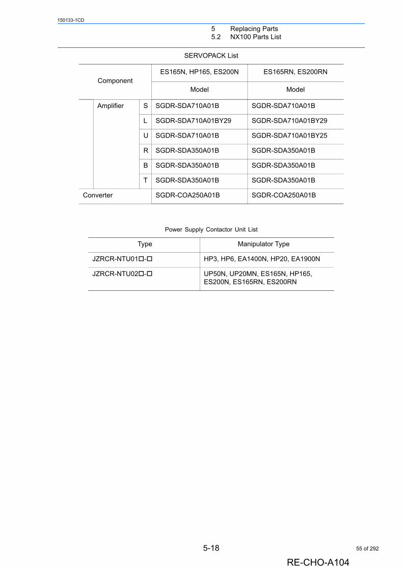
5 Replacing Parts5.2 NX100 Parts List
150133-1CD
Amplifier S SGDR-SDA710A01B SGDR-SDA710A01B
L SGDR-SDA710A01BY29 SGDR-SDA710A01BY29
U SGDR-SDA710A01B SGDR-SDA710A01BY25
R SGDR-SDA350A01B SGDR-SDA350A01B
B SGDR-SDA350A01B SGDR-SDA350A01B
T SGDR-SDA350A01B SGDR-SDA350A01B
Converter SGDR-COA250A01B SGDR-COA250A01B
Power Supply Contactor Unit List
Type Manipulator Type
JZRCR-NTU01- HP3, HP6, EA1400N, HP20, EA1900N
JZRCR-NTU02- UP50N, UP20MN, ES165N, HP165, ES200N, ES165RN, ES200RN
SERVOPACK List
ComponentES165N, HP165, ES200N ES165RN, ES200RN
Model Model
5-18
RE-CHO-A104
55 of 292
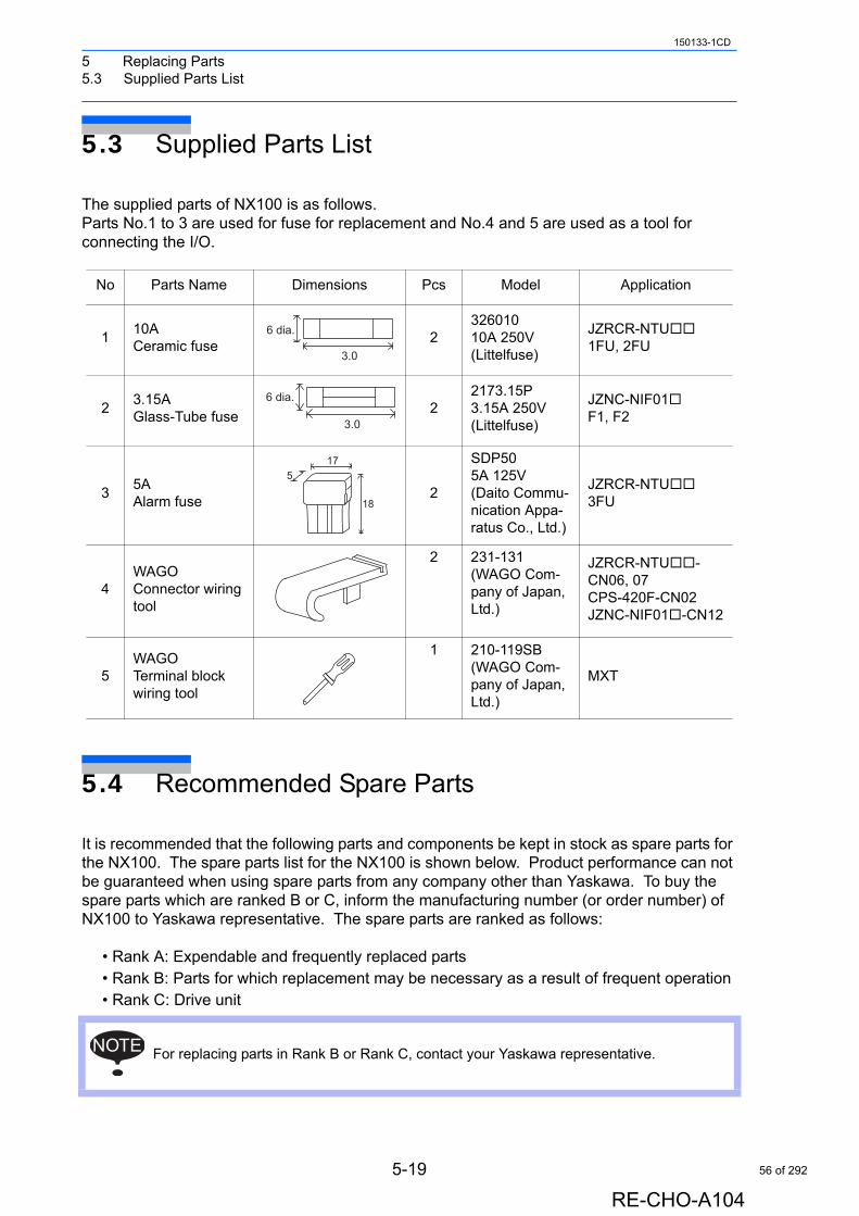
5 Replacing Parts5.3 Supplied Parts List
150133-1CD
5.3 Supplied Parts List
The supplied parts of NX100 is as follows.Parts No.1 to 3 are used for fuse for replacement and No.4 and 5 are used as a tool for connecting the I/O.
5.4 Recommended Spare Parts
It is recommended that the following parts and components be kept in stock as spare parts for the NX100. The spare parts list for the NX100 is shown below. Product performance can not be guaranteed when using spare parts from any company other than Yaskawa. To buy the spare parts which are ranked B or C, inform the manufacturing number (or order number) of NX100 to Yaskawa representative. The spare parts are ranked as follows:
• Rank A: Expendable and frequently replaced parts• Rank B: Parts for which replacement may be necessary as a result of frequent operation• Rank C: Drive unit
No Parts Name Dimensions Pcs Model Application
110ACeramic fuse
232601010A 250V(Littelfuse)
JZRCR-NTU1FU, 2FU
23.15AGlass-Tube fuse
22173.15P3.15A 250V(Littelfuse)
JZNC-NIF01F1, F2
35AAlarm fuse
2
SDP505A 125V(Daito Commu-nication Appa-ratus Co., Ltd.)
JZRCR-NTU3FU
4WAGOConnector wiringtool
2 231-131(WAGO Com-pany of Japan, Ltd.)
JZRCR-NTU-CN06, 07CPS-420F-CN02JZNC-NIF01-CN12
5WAGOTerminal block wiring tool
1 210-119SB(WAGO Com-pany of Japan, Ltd.)
MXT
For replacing parts in Rank B or Rank C, contact your Yaskawa representative.
3.0
6 dia.
3.0
6 dia.
17
18
5
NOTE
5-19
RE-CHO-A104
56 of 292
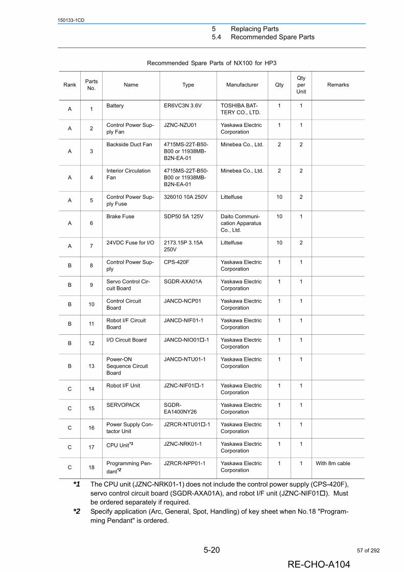
5 Replacing Parts5.4 Recommended Spare Parts
150133-1CD
*1 The CPU unit (JZNC-NRK01-1) does not include the control power supply (CPS-420F), servo control circuit board (SGDR-AXA01A), and robot I/F unit (JZNC-NIF01). Must be ordered separately if required.
*2 Specify application (Arc, General, Spot, Handling) of key sheet when No.18 "Program-ming Pendant" is ordered.
Recommended Spare Parts of NX100 for HP3
RankPartsNo.
Name Type Manufacturer QtyQtyperUnit
Remarks
A 1Battery ER6VC3N 3.6V TOSHIBA BAT-
TERY CO., LTD.1 1
A 2Control Power Sup-ply Fan
JZNC-NZU01 Yaskawa Electric Corporation
1 1
A 3Backside Duct Fan 4715MS-22T-B50-
B00 or 11938MB-B2N-EA-01
Minebea Co., Ltd. 2 2
A 4Interior Circulation Fan
4715MS-22T-B50-B00 or 11938MB-B2N-EA-01
Minebea Co., Ltd. 2 2
A 5Control Power Sup-ply Fuse
326010 10A 250V Littelfuse 10 2
A 6Brake Fuse SDP50 5A 125V Daito Communi-
cation Apparatus Co., Ltd.
10 1
A 724VDC Fuse for I/O 2173.15P 3.15A
250VLittelfuse 10 2
B 8Control Power Sup-ply
CPS-420F Yaskawa Electric Corporation
1 1
B 9Servo Control Cir-cuit Board
SGDR-AXA01A Yaskawa Electric Corporation
1 1
B 10Control Circuit Board
JANCD-NCP01 Yaskawa Electric Corporation
1 1
B 11Robot I/F Circuit Board
JANCD-NIF01-1 Yaskawa Electric Corporation
1 1
B 12I/O Circuit Board JANCD-NIO01-1 Yaskawa Electric
Corporation1 1
B 13Power-ON Sequence Circuit Board
JANCD-NTU01-1 Yaskawa Electric Corporation
1 1
C 14Robot I/F Unit JZNC-NIF01-1 Yaskawa Electric
Corporation1 1
C 15SERVOPACK SGDR-
EA1400NY26Yaskawa Electric Corporation
1 1
C 16Power Supply Con-tactor Unit
JZRCR-NTU01-1 Yaskawa Electric Corporation
1 1
C 17 CPU Unit*1 JZNC-NRK01-1 Yaskawa Electric Corporation
1 1
C 18Programming Pen-
dant*2JZRCR-NPP01-1 Yaskawa Electric
Corporation1 1 With 8m cable
5-20
RE-CHO-A104
57 of 292
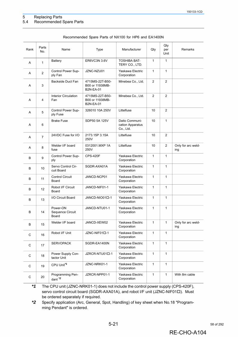
5 Replacing Parts5.4 Recommended Spare Parts
150133-1CD
*1 The CPU unit (JZNC-NRK01-1) does not include the control power supply (CPS-420F), servo control circuit board (SGDR-AXA01A), and robot I/F unit (JZNC-NIF01). Must be ordered separately if required.
*2 Specify application (Arc, General, Spot, Handling) of key sheet when No.18 "Program-ming Pendant" is ordered.
Recommended Spare Parts of NX100 for HP6 and EA1400N
RankPartsNo.
Name Type Manufacturer QtyQtyperUnit
Remarks
A 1Battery ER6VC3N 3.6V TOSHIBA BAT-
TERY CO., LTD.1 1
A 2Control Power Sup-ply Fan
JZNC-NZU01 Yaskawa Electric Corporation
1 1
A 3Backside Duct Fan 4715MS-22T-B50-
B00 or 11938MB-B2N-EA-01
Minebea Co., Ltd. 2 2
A 4Interior Circulation Fan
4715MS-22T-B50-B00 or 11938MB-B2N-EA-01
Minebea Co., Ltd. 2 2
A 5Control Power Sup-ply Fuse
326010 10A 250V Littelfuse 10 2
A 6Brake Fuse SDP50 5A 125V Daito Communi-
cation Apparatus Co., Ltd.
10 1
A 724VDC Fuse for I/O 2173.15P 3.15A
250VLittelfuse 10 2
A 8Welder I/F board fuse
0312001.MXP 1A 250V
Littelfuse 10 2 Only for arc weld-ing
B 9Control Power Sup-ply
CPS-420F Yaskawa Electric Corporation
1 1
B 10Servo Control Cir-cuit Board
SGDR-AXA01A Yaskawa Electric Corporation
1 1
B 11Control Circuit Board
JANCD-NCP01 Yaskawa Electric Corporation
1 1
B 12Robot I/F Circuit Board
JANCD-NIF01-1 Yaskawa Electric Corporation
1 1
B 13I/O Circuit Board JANCD-NIO01-1 Yaskawa Electric
Corporation1 1
B 14Power-ON Sequence Circuit Board
JANCD-NTU01-1 Yaskawa Electric Corporation
1 1
B 15Welder I/F board JANCD-XEW02 Yaskawa Electric
Corporation1 1 Only for arc weld-
ing
C 16Robot I/F Unit JZNC-NIF01-1 Yaskawa Electric
Corporation1 1
C 17SERVOPACK SGDR-EA1400N Yaskawa Electric
Corporation1 1
C 18Power Supply Con-tactor Unit
JZRCR-NTU01-1 Yaskawa Electric Corporation
1 1
C 19 CPU Unit*1 JZNC-NRK01-1 Yaskawa Electric Corporation
1 1
C 20Programming Pen-
dant *2JZRCR-NPP01-1 Yaskawa Electric
Corporation1 1 With 8m cable
5-21
RE-CHO-A104
58 of 292
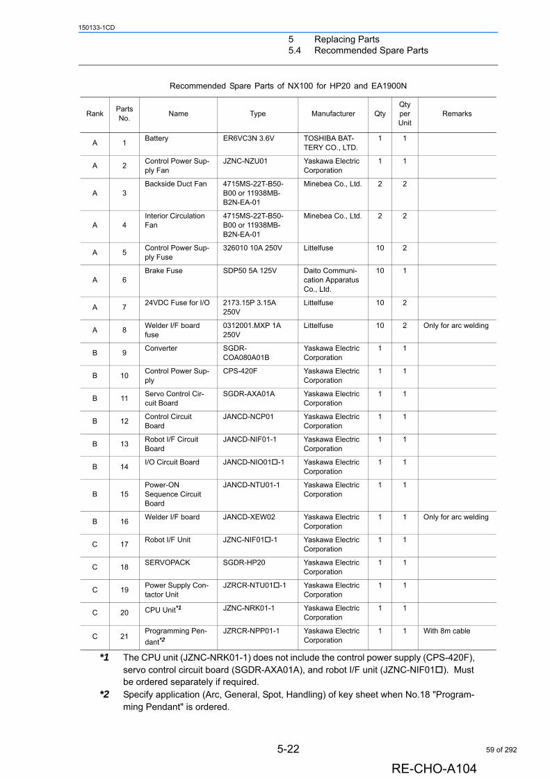
5 Replacing Parts5.4 Recommended Spare Parts
150133-1CD
*1 The CPU unit (JZNC-NRK01-1) does not include the control power supply (CPS-420F), servo control circuit board (SGDR-AXA01A), and robot I/F unit (JZNC-NIF01). Must be ordered separately if required.
*2 Specify application (Arc, General, Spot, Handling) of key sheet when No.18 "Program-ming Pendant" is ordered.
Recommended Spare Parts of NX100 for HP20 and EA1900N
RankPartsNo.
Name Type Manufacturer QtyQtyperUnit
Remarks
A 1Battery ER6VC3N 3.6V TOSHIBA BAT-
TERY CO., LTD.1 1
A 2Control Power Sup-ply Fan
JZNC-NZU01 Yaskawa Electric Corporation
1 1
A 3Backside Duct Fan 4715MS-22T-B50-
B00 or 11938MB-B2N-EA-01
Minebea Co., Ltd. 2 2
A 4Interior Circulation Fan
4715MS-22T-B50-B00 or 11938MB-B2N-EA-01
Minebea Co., Ltd. 2 2
A 5Control Power Sup-ply Fuse
326010 10A 250V Littelfuse 10 2
A 6Brake Fuse SDP50 5A 125V Daito Communi-
cation Apparatus Co., Ltd.
10 1
A 724VDC Fuse for I/O 2173.15P 3.15A
250VLittelfuse 10 2
A 8Welder I/F board fuse
0312001.MXP 1A 250V
Littelfuse 10 2 Only for arc welding
B 9Converter SGDR-
COA080A01BYaskawa Electric Corporation
1 1
B 10Control Power Sup-ply
CPS-420F Yaskawa Electric Corporation
1 1
B 11Servo Control Cir-cuit Board
SGDR-AXA01A Yaskawa Electric Corporation
1 1
B 12Control Circuit Board
JANCD-NCP01 Yaskawa Electric Corporation
1 1
B 13Robot I/F Circuit Board
JANCD-NIF01-1 Yaskawa Electric Corporation
1 1
B 14I/O Circuit Board JANCD-NIO01-1 Yaskawa Electric
Corporation1 1
B 15Power-ON Sequence Circuit Board
JANCD-NTU01-1 Yaskawa Electric Corporation
1 1
B 16Welder I/F board JANCD-XEW02 Yaskawa Electric
Corporation1 1 Only for arc welding
C 17Robot I/F Unit JZNC-NIF01-1 Yaskawa Electric
Corporation1 1
C 18SERVOPACK SGDR-HP20 Yaskawa Electric
Corporation1 1
C 19Power Supply Con-tactor Unit
JZRCR-NTU01-1 Yaskawa Electric Corporation
1 1
C 20 CPU Unit*1 JZNC-NRK01-1 Yaskawa Electric Corporation
1 1
C 21Programming Pen-
dant*2JZRCR-NPP01-1 Yaskawa Electric
Corporation1 1 With 8m cable
5-22
RE-CHO-A104
59 of 292
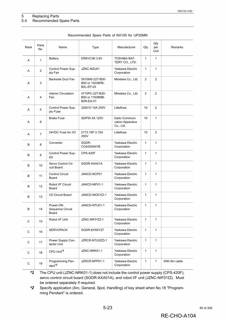
5 Replacing Parts5.4 Recommended Spare Parts
150133-1CD
*1 The CPU unit (JZNC-NRK01-1) does not include the control power supply (CPS-420F), servo control circuit board (SGDR-AXA01A), and robot I/F unit (JZNC-NIF01). Must be ordered separately if required.
*2 Specify application (Arc, General, Spot, Handling) of key sheet when No.18 "Program-ming Pendant" is ordered.
Recommended Spare Parts of NX100 for UP20MN
RankPartsNo.
Name Type Manufacturer QtyQtyperUnit
Remarks
A 1Battery ER6VC3N 3.6V TOSHIBA BAT-
TERY CO., LTD.1 1
A 2Control Power Sup-ply Fan
JZNC-NZU01 Yaskawa Electric Corporation
1 1
A 3Backside Duct Fan 5915MS-22T-B50-
B00 or 15038PB-B2L-EP-03
Minebea Co., Ltd. 2 2
A 4Interior Circulation Fan
4715PC-22T-B30-B00 or 11938MB-B2N-EA-01
Minebea Co., Ltd. 2 2
A 5Control Power Sup-ply Fuse
326010 10A 250V Littelfuse 10 2
A 6Brake Fuse SDP50 5A 125V Daito Communi-
cation Apparatus Co., Ltd.
10 1
A 724VDC Fuse for I/O 2173.15P 3.15A
250VLittelfuse 10 2
B 8Converter SGDR-
COA250A01BYaskawa Electric Corporation
1 1
B 9Control Power Sup-ply
CPS-420F Yaskawa Electric Corporation
1 1
B 10Servo Control Cir-cuit Board
SGDR-AXA01A Yaskawa Electric Corporation
1 1
B 11Control Circuit Board
JANCD-NCP01 Yaskawa Electric Corporation
1 1
B 12Robot I/F Circuit Board
JANCD-NIF01-1 Yaskawa Electric Corporation
1 1
B 13I/O Circuit Board JANCD-NIO01-1 Yaskawa Electric
Corporation1 1
B 14Power-ON Sequence Circuit Board
JANCD-NTU01-1 Yaskawa Electric Corporation
1 1
C 15Robot I/F Unit JZNC-NIF01-1 Yaskawa Electric
Corporation1 1
C 16SERVOPACK SGDR-EH50Y27 Yaskawa Electric
Corporation1 1
C 17Power Supply Con-tactor Unit
JZRCR-NTU02-1 Yaskawa Electric Corporation
1 1
C 18 CPU Unit*1 JZNC-NRK01-1 Yaskawa Electric Corporation
1 1
C 19Programming Pen-
dant*2JZRCR-NPP01-1 Yaskawa Electric
Corporation1 1 With 8m cable
5-23
RE-CHO-A104
60 of 292
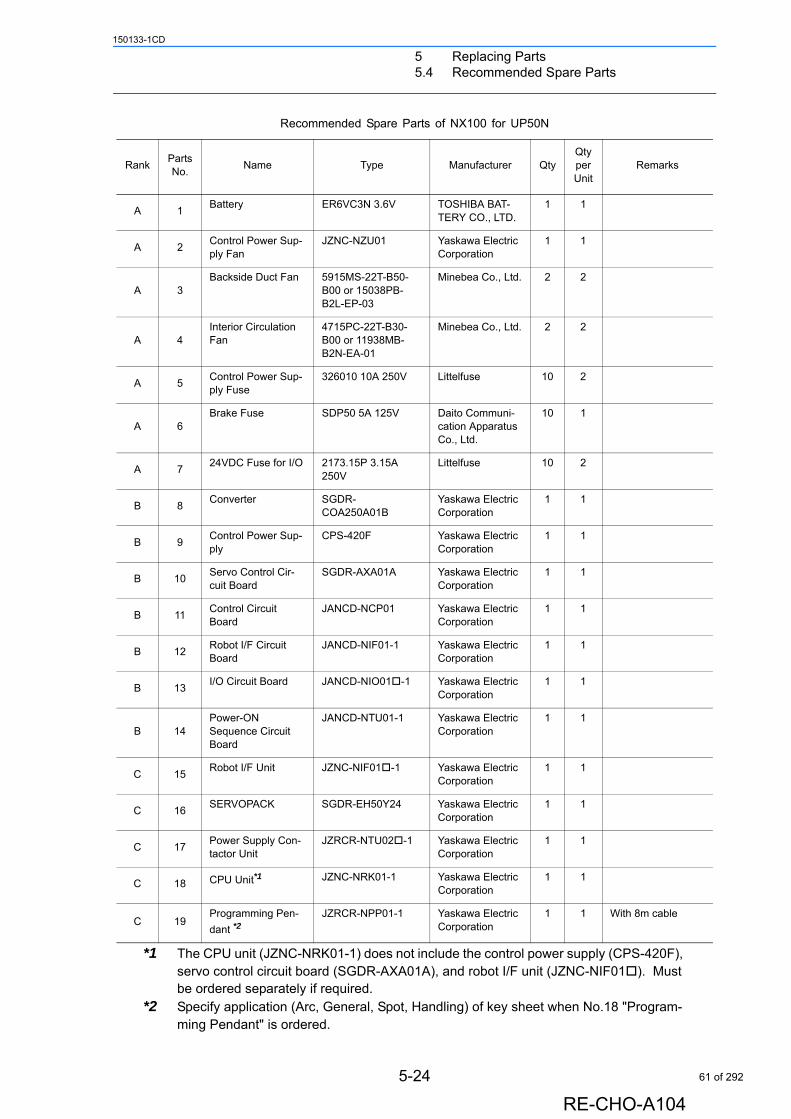
5 Replacing Parts5.4 Recommended Spare Parts
150133-1CD
*1 The CPU unit (JZNC-NRK01-1) does not include the control power supply (CPS-420F), servo control circuit board (SGDR-AXA01A), and robot I/F unit (JZNC-NIF01). Must be ordered separately if required.
*2 Specify application (Arc, General, Spot, Handling) of key sheet when No.18 "Program-ming Pendant" is ordered.
Recommended Spare Parts of NX100 for UP50N
RankPartsNo.
Name Type Manufacturer QtyQtyperUnit
Remarks
A 1Battery ER6VC3N 3.6V TOSHIBA BAT-
TERY CO., LTD.1 1
A 2Control Power Sup-ply Fan
JZNC-NZU01 Yaskawa Electric Corporation
1 1
A 3Backside Duct Fan 5915MS-22T-B50-
B00 or 15038PB-B2L-EP-03
Minebea Co., Ltd. 2 2
A 4Interior Circulation Fan
4715PC-22T-B30-B00 or 11938MB-B2N-EA-01
Minebea Co., Ltd. 2 2
A 5Control Power Sup-ply Fuse
326010 10A 250V Littelfuse 10 2
A 6Brake Fuse SDP50 5A 125V Daito Communi-
cation Apparatus Co., Ltd.
10 1
A 724VDC Fuse for I/O 2173.15P 3.15A
250VLittelfuse 10 2
B 8Converter SGDR-
COA250A01BYaskawa Electric Corporation
1 1
B 9Control Power Sup-ply
CPS-420F Yaskawa Electric Corporation
1 1
B 10Servo Control Cir-cuit Board
SGDR-AXA01A Yaskawa Electric Corporation
1 1
B 11Control Circuit Board
JANCD-NCP01 Yaskawa Electric Corporation
1 1
B 12Robot I/F Circuit Board
JANCD-NIF01-1 Yaskawa Electric Corporation
1 1
B 13I/O Circuit Board JANCD-NIO01-1 Yaskawa Electric
Corporation1 1
B 14Power-ON Sequence Circuit Board
JANCD-NTU01-1 Yaskawa Electric Corporation
1 1
C 15Robot I/F Unit JZNC-NIF01-1 Yaskawa Electric
Corporation1 1
C 16SERVOPACK SGDR-EH50Y24 Yaskawa Electric
Corporation1 1
C 17Power Supply Con-tactor Unit
JZRCR-NTU02-1 Yaskawa Electric Corporation
1 1
C 18 CPU Unit*1 JZNC-NRK01-1 Yaskawa Electric Corporation
1 1
C 19Programming Pen-
dant *2JZRCR-NPP01-1 Yaskawa Electric
Corporation1 1 With 8m cable
5-24
RE-CHO-A104
61 of 292
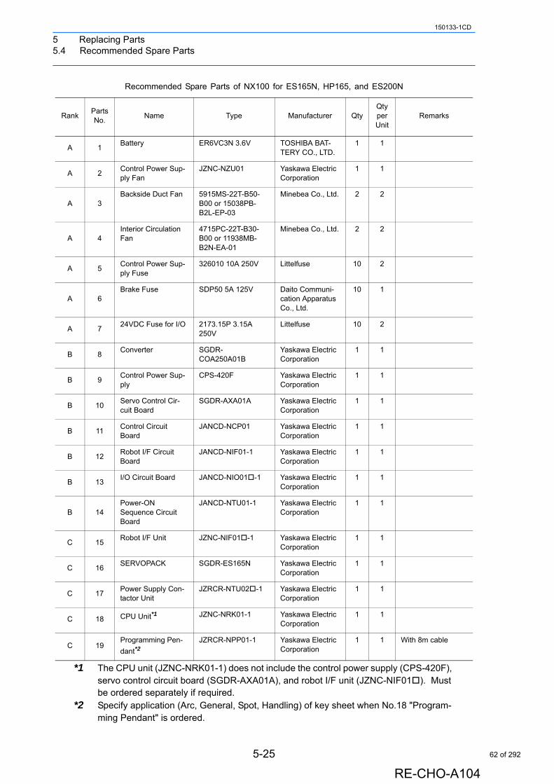
5 Replacing Parts5.4 Recommended Spare Parts
150133-1CD
*1 The CPU unit (JZNC-NRK01-1) does not include the control power supply (CPS-420F), servo control circuit board (SGDR-AXA01A), and robot I/F unit (JZNC-NIF01). Must be ordered separately if required.
*2 Specify application (Arc, General, Spot, Handling) of key sheet when No.18 "Program-ming Pendant" is ordered.
Recommended Spare Parts of NX100 for ES165N, HP165, and ES200N
RankPartsNo.
Name Type Manufacturer QtyQtyperUnit
Remarks
A 1Battery ER6VC3N 3.6V TOSHIBA BAT-
TERY CO., LTD.1 1
A 2Control Power Sup-ply Fan
JZNC-NZU01 Yaskawa Electric Corporation
1 1
A 3Backside Duct Fan 5915MS-22T-B50-
B00 or 15038PB-B2L-EP-03
Minebea Co., Ltd. 2 2
A 4Interior Circulation Fan
4715PC-22T-B30-B00 or 11938MB-B2N-EA-01
Minebea Co., Ltd. 2 2
A 5Control Power Sup-ply Fuse
326010 10A 250V Littelfuse 10 2
A 6Brake Fuse SDP50 5A 125V Daito Communi-
cation Apparatus Co., Ltd.
10 1
A 724VDC Fuse for I/O 2173.15P 3.15A
250VLittelfuse 10 2
B 8Converter SGDR-
COA250A01BYaskawa Electric Corporation
1 1
B 9Control Power Sup-ply
CPS-420F Yaskawa Electric Corporation
1 1
B 10Servo Control Cir-cuit Board
SGDR-AXA01A Yaskawa Electric Corporation
1 1
B 11Control Circuit Board
JANCD-NCP01 Yaskawa Electric Corporation
1 1
B 12Robot I/F Circuit Board
JANCD-NIF01-1 Yaskawa Electric Corporation
1 1
B 13I/O Circuit Board JANCD-NIO01-1 Yaskawa Electric
Corporation1 1
B 14Power-ON Sequence Circuit Board
JANCD-NTU01-1 Yaskawa Electric Corporation
1 1
C 15Robot I/F Unit JZNC-NIF01-1 Yaskawa Electric
Corporation1 1
C 16SERVOPACK SGDR-ES165N Yaskawa Electric
Corporation1 1
C 17Power Supply Con-tactor Unit
JZRCR-NTU02-1 Yaskawa Electric Corporation
1 1
C 18 CPU Unit*1 JZNC-NRK01-1 Yaskawa Electric Corporation
1 1
C 19Programming Pen-
dant*2JZRCR-NPP01-1 Yaskawa Electric
Corporation1 1 With 8m cable
5-25
RE-CHO-A104
62 of 292
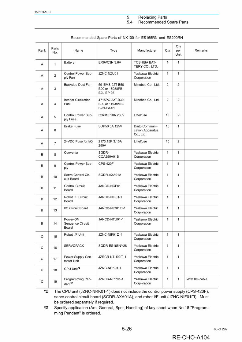
5 Replacing Parts5.4 Recommended Spare Parts
150133-1CD
*1 The CPU unit (JZNC-NRK01-1) does not include the control power supply (CPS-420F), servo control circuit board (SGDR-AXA01A), and robot I/F unit (JZNC-NIF01). Must be ordered separately if required.
*2 Specify application (Arc, General, Spot, Handling) of key sheet when No.18 "Program-ming Pendant" is ordered.
Recommended Spare Parts of NX100 for ES165RN and ES200RN
RankPartsNo.
Name Type Manufacturer QtyQtyperUnit
Remarks
A 1Battery ER6VC3N 3.6V TOSHIBA BAT-
TERY CO., LTD.1 1
A 2Control Power Sup-ply Fan
JZNC-NZU01 Yaskawa Electric Corporation
1 1
A 3Backside Duct Fan 5915MS-22T-B50-
B00 or 15038PB-B2L-EP-03
Minebea Co., Ltd. 2 2
A 4Interior Circulation Fan
4715PC-22T-B30-B00 or 11938MB-B2N-EA-01
Minebea Co., Ltd. 2 2
A 5Control Power Sup-ply Fuse
326010 10A 250V Littelfuse 10 2
A 6Brake Fuse SDP50 5A 125V Daito Communi-
cation Apparatus Co., Ltd.
10 1
A 724VDC Fuse for I/O 2173.15P 3.15A
250VLittelfuse 10 2
B 8Converter SGDR-
COA250A01BYaskawa Electric Corporation
1 1
B 9Control Power Sup-ply
CPS-420F Yaskawa Electric Corporation
1 1
B 10Servo Control Cir-cuit Board
SGDR-AXA01A Yaskawa Electric Corporation
1 1
B 11Control Circuit Board
JANCD-NCP01 Yaskawa Electric Corporation
1 1
B 12Robot I/F Circuit Board
JANCD-NIF01-1 Yaskawa Electric Corporation
1 1
B 13I/O Circuit Board JANCD-NIO01-1 Yaskawa Electric
Corporation1 1
B 14Power-ON Sequence Circuit Board
JANCD-NTU01-1 Yaskawa Electric Corporation
1 1
C 15Robot I/F Unit JZNC-NIF01-1 Yaskawa Electric
Corporation1 1
C 16SERVOPACK SGDR-ES165NY28 Yaskawa Electric
Corporation1 1
C 17Power Supply Con-tactor Unit
JZRCR-NTU02-1 Yaskawa Electric Corporation
1 1
C 18 CPU Unit*1 JZNC-NRK01-1 Yaskawa Electric Corporation
1 1
C 19Programming Pen-
dant*2JZRCR-NPP01-1 Yaskawa Electric
Corporation1 1 With 8m cable
5-26
RE-CHO-A104
63 of 292
6 Operations after Replacing Parts
150133-1CD
6 Operations after Replacing Parts
• Before operating the manipulator, check that the SERVO ON lamp turns OFF when the emergency stop buttons on the front door of the NX100 and the programming pendant are pressed.
Injury or damage to machinery may result if the manipulator cannot be stopped in case of an emergency.
• Observe the following precautions when performing teaching operations within the P-point maximum envelope of the manipulator:
- Be sure to use a lockout device to the safeguarding when going inside. Also, display the sign that the operation is being performed inside the safeguarding and make sure no one closes the safeguarding.- View the manipulator from the front whenever possible.- Always follow the predetermined operating procedure.- Ensure that you have a safe place to retreat in case of emergency.
Improper or unintended manipulator operation may result in injury.
• Confirm that no persons are present in the P-point maximum envelope of the manipulator and that you are in a safe location before:
- Turning ON the NX100 power.- Moving the manipulator with the programming pendant
Injury may result if anyone enters the P-point maximum envelope of the manipulator during operation.
• Always press the emergency stop button immediately if there are problems.
Emergency stop buttons are located at the upper right corner of the front door of the NX100 and on the upper right of the programming pendant.
6-1
RE-CHO-A104
64 of 292
6 Operations after Replacing Parts6.1 Home Position Calibration
150133-1CD
6.1 Home Position Calibration
6.1.1 Home Position Calibration
Home position calibration is an operation in which the home position and absolute encoder position coincide. Although this operation is performed prior to shipment at the factory, the following cases require this operation to be performed again.
• Change in the combination of the manipulator and NX100• Replacement of the motor or absolute encoder• Clearing stored memory (by replacement of NIF01 circuit board, weak battery, etc.)• Home position deviation caused by hitting the manipulator against a workpiece, etc.
To calibrate the home position, use the axis keys to calibrate the mark for the home position on each axis so that the manipulator can take its posture for the home position. There are two operations for home position calibration:
• All the axes can be moved at the same time• Axes can be moved individually
• Perform the following inspection procedures prior to conducting manipulator teaching. If problems are found, repair them immediately, and be sure that all other necessary processing has been performed.
- Check for problems in manipulator movement.- Check for damage to insulation and sheathing of external wires.
• Always return the programming pendant to the hook on the NX100 cabinet after use.
The programming pendant can be damaged if it is left in the P-point maximum envelope of the manipulator, on the floor, or near fixtures.
Teaching and playback are not possible before home position calibration is complete.In a system with two or more manipulators, the home position of all the manipulators must be calibrated before starting teaching or playback.Set the security mode to the management mode to perform home position calibration.
NOTE
6-2
RE-CHO-A104
65 of 292
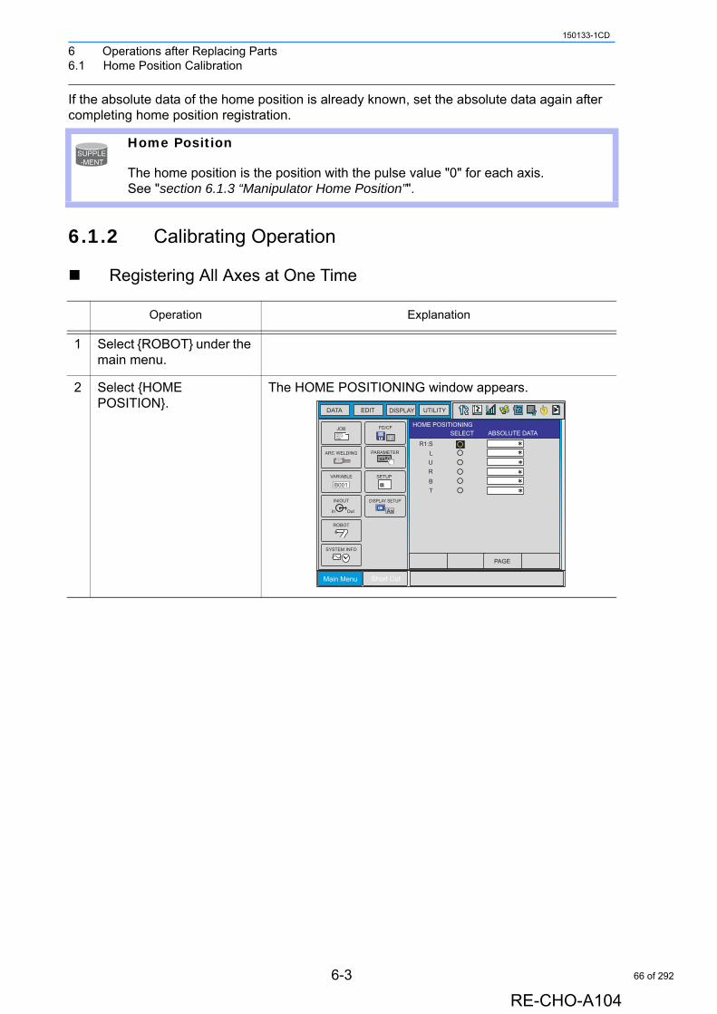
6 Operations after Replacing Parts6.1 Home Position Calibration
150133-1CD
If the absolute data of the home position is already known, set the absolute data again after completing home position registration.
6.1.2 Calibrating Operation
Registering All Axes at One Time
Home Position
The home position is the position with the pulse value "0" for each axis. See "section 6.1.3 “Manipulator Home Position”".
Operation Explanation
1 Select {ROBOT} under the main menu.
2 Select {HOME POSITION}.
The HOME POSITIONING window appears.
SUPPLE-MENT
Main Menu Short Cut
JOBDOUTMOVEEND
IN/OUT
In Out
SYSTEM INFO
ARC WELDING
VARIABLE
B001
ROBOT
CF
FD/CF
SETUP
PARAMETER
DISPLAY SETUP
Aa
DATA EDIT DISPLAY UTILITY T
PAGE
HOME POSITIONINGSELECT ABSOLUTE DATA
R1:SLURBT
6-3
RE-CHO-A104
66 of 292
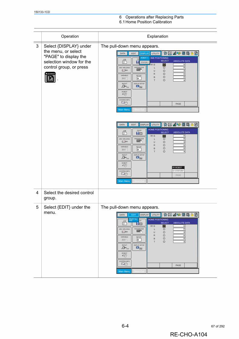
6 Operations after Replacing Parts6.1 Home Position Calibration
150133-1CD
3 Select {DISPLAY} under the menu, or select "PAGE" to display the selection window for the control group, or press
.
The pull-down menu appears.
4 Select the desired control group.
5 Select {EDIT} under the menu.
The pull-down menu appears.
Operation Explanation
PAGE
GO BACK
Main Menu Short Cut
JOBDOUTMOVEEND
IN/OUT
In Out
SYSTEM INFO
ARC WELDING
VARIABLE
B001
ROBOT
CF
FD/CF
SETUP
PARAMETER
DISPLAY SETUP
Aa
DATA EDIT DISPLAY UTILITY T
PAGE
HOME POSITIONINGSELECT ABSOLUTE DATA
R1:SLURBT
ROBOT 1
STATION 1
Main Menu Short Cut
JOBDOUTMOVEEND
IN/OUT
In Out
SYSTEM INFO
ARC WELDING
VARIABLE
B001
ROBOT
CF
FD/CF
SETUP
PARAMETER
DISPLAY SETUP
Aa
DATA EDIT DISPLAY UTILITY T
PAGE
HOME POSITIONINGSELECT ABSOLUTE DATA
R1:SLURBT
S1:STATION1R1:ROBOT
Main Menu Short Cut
JOBDOUTMOVEEND
IN/OUT
In Out
SYSTEM INFO
ARC WELDING
VARIABLE
B001
ROBOT
CF
FD/CF
SETUP
PARAMETER
DISPLAY SETUP
Aa
DATA EDIT DISPLAY UTILITY T
PAGE
HOME POSITIONINGSELECT ABSOLUTE DATA
R1:SLURBT
SELECT ALL AXIS
6-4
RE-CHO-A104
67 of 292
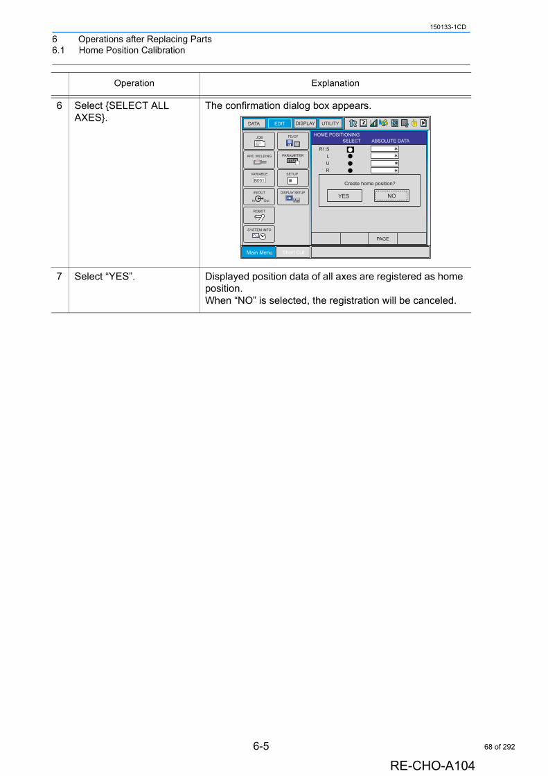
6 Operations after Replacing Parts6.1 Home Position Calibration
150133-1CD
6 Select {SELECT ALL AXES}.
The confirmation dialog box appears.
7 Select “YES”. Displayed position data of all axes are registered as home position.When “NO” is selected, the registration will be canceled.
Operation Explanation
Main Menu Short Cut
JOBDOUTMOVEEND
IN/OUT
In Out
SYSTEM INFO
ARC WELDING
VARIABLE
B001
ROBOT
CF
FD/CF
SETUP
PARAMETER
DISPLAY SETUP
Aa
DATA EDIT DISPLAY UTILITY T
PAGE
HOME POSITIONINGSELECT ABSOLUTE DATA
R1:SLURBT
¡¡
YES NO
Create home position?
6-5
RE-CHO-A104
68 of 292
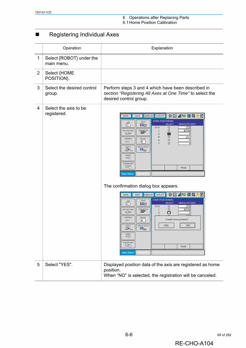
6 Operations after Replacing Parts6.1 Home Position Calibration
150133-1CD
Registering Individual Axes
Operation Explanation
1 Select {ROBOT} under the main menu.
2 Select {HOME POSITION}.
3 Select the desired control group.
Perform steps 3 and 4 which have been described in section “Registering All Axes at One Time” to select the desired control group.
4 Select the axis to be registered.
The confirmation dialog box appears.
5 Select "YES". Displayed position data of the axis are registered as home position.When “NO” is selected, the registration will be canceled.
Main Menu Short Cut
JOBDOUTMOVEEND
IN/OUT
In Out
SYSTEM INFO
ARC WELDING
VARIABLE
B001
ROBOT
CF
FD/CF
SETUP
PARAMETER
DISPLAY SETUP
Aa
DATA EDIT DISPLAY UTILITY T
PAGE
HOME POSITIONINGSELECT ABSOLUTE DATA
R1:SLURBT
30154
-217
-278
Main Menu Short Cut
JOBDOUTMOVEEND
IN/OUT
In Out
SYSTEM INFO
ARC WELDING
VARIABLE
B001
ROBOT
CF
FD/CF
SETUP
PARAMETER
DISPLAY SETUP
Aa
DATA EDIT DISPLAY UTILITY T
PAGE
HOME POSITIONINGSELECT ABSOLUTE DATA
R1:SLURBT
30154
-217
-278
YES NO
Create home position?
6-6
RE-CHO-A104
69 of 292
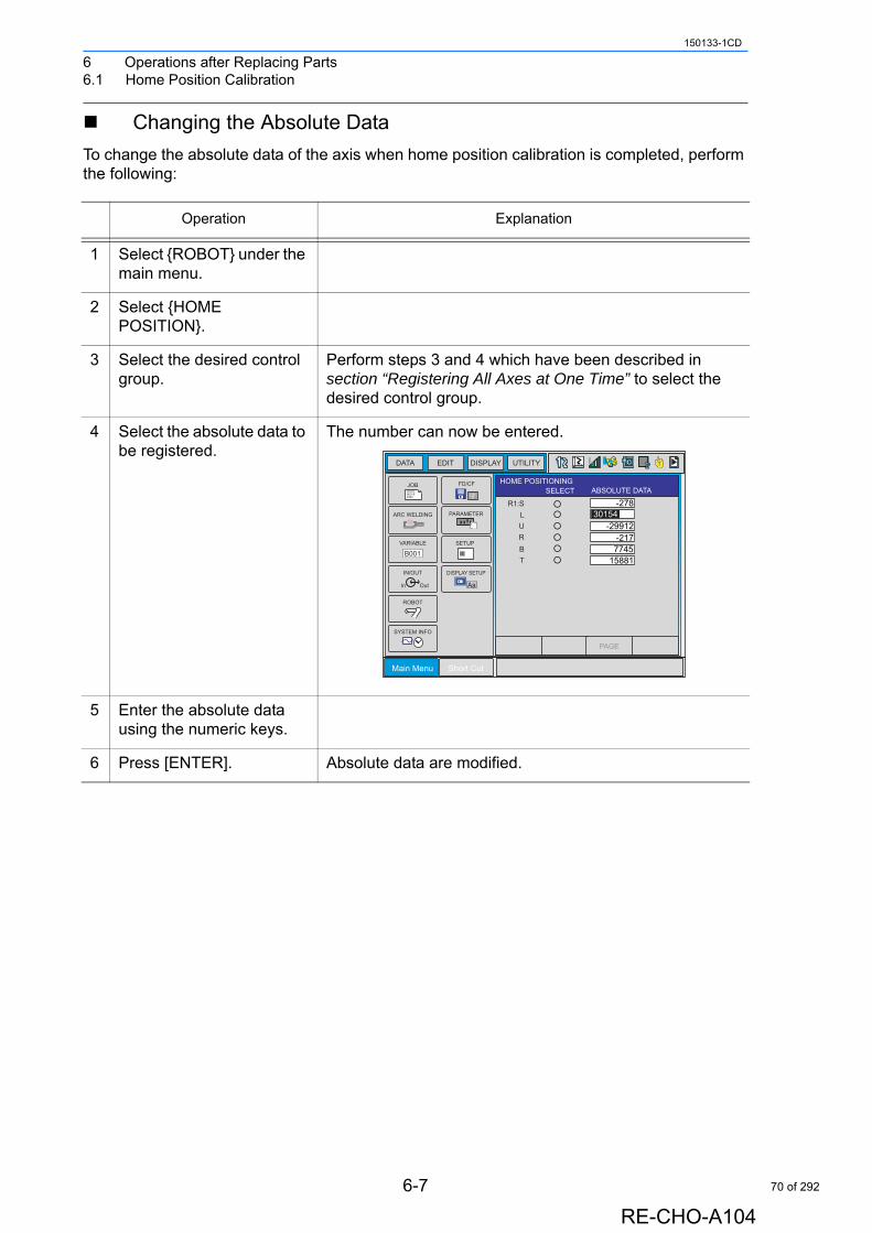
6 Operations after Replacing Parts6.1 Home Position Calibration
150133-1CD
Changing the Absolute Data
To change the absolute data of the axis when home position calibration is completed, perform the following:
Operation Explanation
1 Select {ROBOT} under the main menu.
2 Select {HOME POSITION}.
3 Select the desired control group.
Perform steps 3 and 4 which have been described in section “Registering All Axes at One Time” to select the desired control group.
4 Select the absolute data to be registered.
The number can now be entered.
5 Enter the absolute data using the numeric keys.
6 Press [ENTER]. Absolute data are modified.
Main Menu Short Cut
JOBDOUTMOVEEND
IN/OUT
In Out
SYSTEM INFO
ARC WELDING
VARIABLE
B001
ROBOT
CF
FD/CF
SETUP
PARAMETER
DISPLAY SETUP
Aa
DATA EDIT DISPLAY UTILITY T
PAGE
HOME POSITIONINGSELECT ABSOLUTE DATA
R1:SLURBT
30154
-217-29912
774515881
-278
6-7
RE-CHO-A104
70 of 292
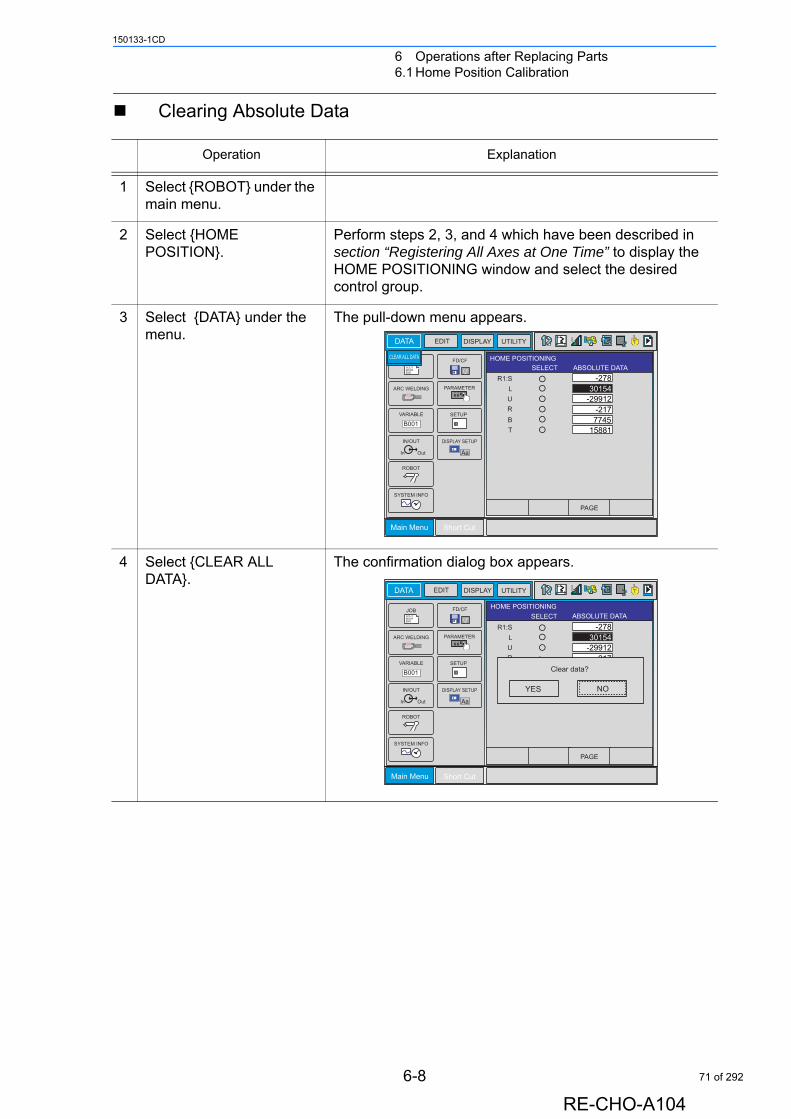
6 Operations after Replacing Parts6.1 Home Position Calibration
150133-1CD
Clearing Absolute Data
Operation Explanation
1 Select {ROBOT} under the main menu.
2 Select {HOME POSITION}.
Perform steps 2, 3, and 4 which have been described in section “Registering All Axes at One Time” to display the HOME POSITIONING window and select the desired control group.
3 Select {DATA} under the menu.
The pull-down menu appears.
4 Select {CLEAR ALL DATA}.
The confirmation dialog box appears.
Main Menu Short Cut
DOUTMOVEEND
IN/OUT
In Out
SYSTEM INFO
ARC WELDING
VARIABLE
B001
ROBOT
CF
FD/CF
SETUP
PARAMETER
DISPLAY SETUP
Aa
DATA EDIT DISPLAY UTILITY T
PAGE
HOME POSITIONINGSELECT ABSOLUTE DATA
R1:SLURBT
30154
-217-29912
774515881
-278
CLEAR ALL DATA
Main Menu Short Cut
JOBDOUTMOVEEND
IN/OUT
In Out
SYSTEM INFO
ARC WELDING
VARIABLE
B001
ROBOT
CF
FD/CF
SETUP
PARAMETER
DISPLAY SETUP
Aa
DATA EDIT DISPLAY UTILITY T
PAGE
HOME POSITIONINGSELECT ABSOLUTE DATA
R1:SLURBT
¡¡¡
-217-29912
774515881
-278
YES NO
Clear data?
30154
6-8
RE-CHO-A104
71 of 292
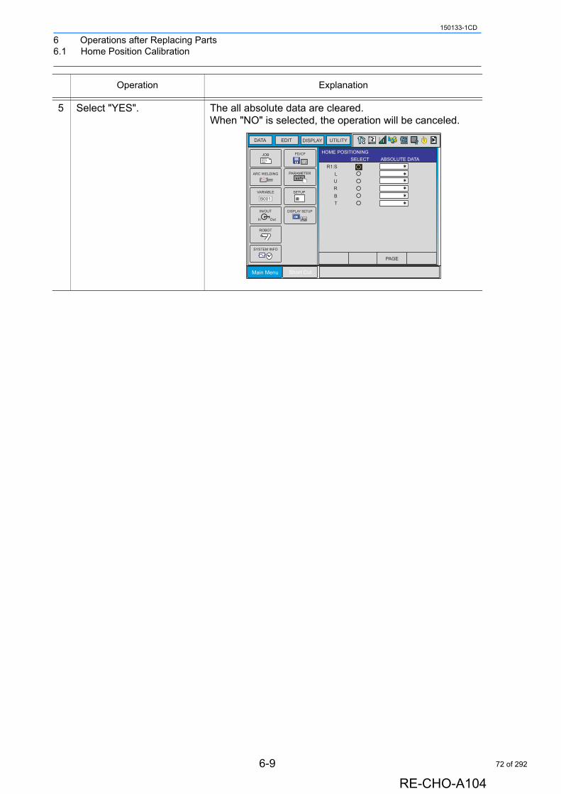
6 Operations after Replacing Parts6.1 Home Position Calibration
150133-1CD
5 Select "YES". The all absolute data are cleared.When "NO" is selected, the operation will be canceled.
Operation Explanation
Main Menu Short Cut
JOBDOUTMOVEEND
IN/OUT
In Out
SYSTEM INFO
ARC WELDING
VARIABLE
B001
ROBOT
CF
FD/CF
SETUP
PARAMETER
DISPLAY SETUP
Aa
DATA EDIT DISPLAY UTILITY T
PAGE
HOME POSITIONINGSELECT ABSOLUTE DATA
R1:SLURBT
6-9
RE-CHO-A104
72 of 292
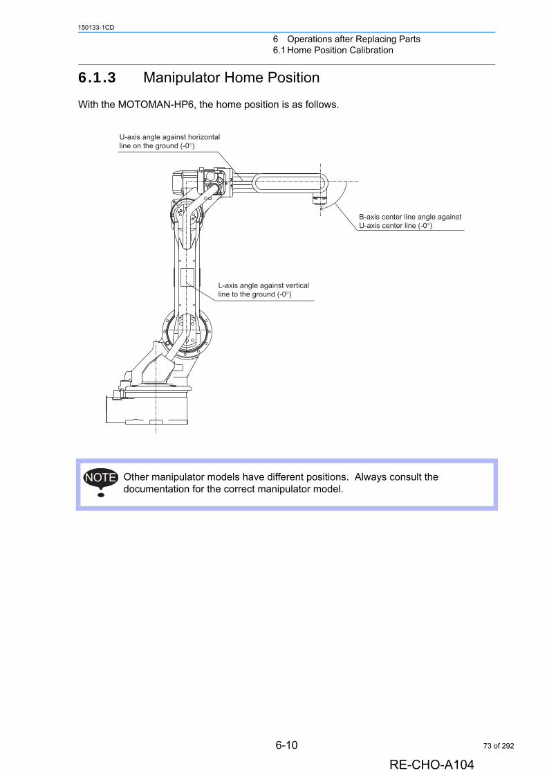
6 Operations after Replacing Parts6.1 Home Position Calibration
150133-1CD
6.1.3 Manipulator Home Position
With the MOTOMAN-HP6, the home position is as follows.
Other manipulator models have different positions. Always consult the documentation for the correct manipulator model.
L-axis angle against verticalline to the ground (-0°)
B-axis center line angle againstU-axis center line (-0°)
U-axis angle against horizontalline on the ground (-0°)
NOTE
6-10
RE-CHO-A104
73 of 292
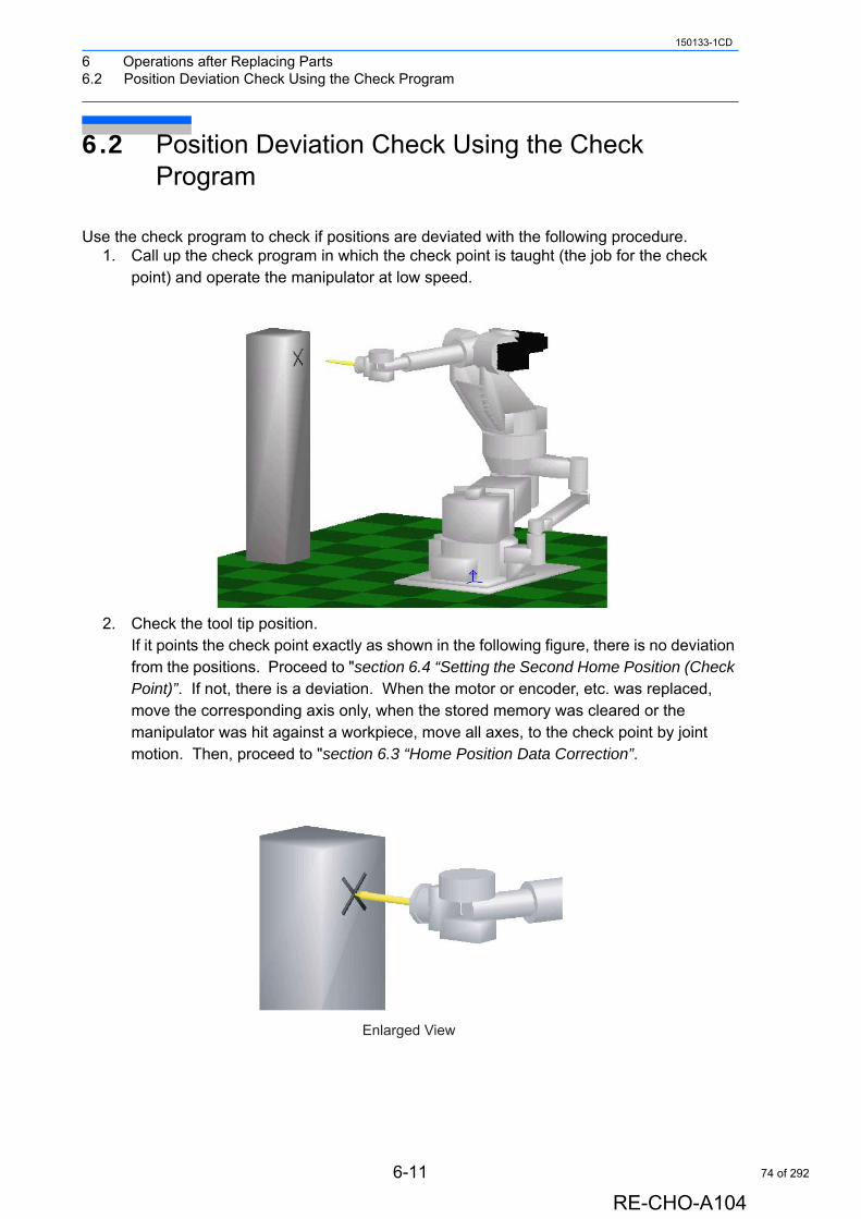
6 Operations after Replacing Parts6.2 Position Deviation Check Using the Check Program
150133-1CD
6.2 Position Deviation Check Using the Check Program
Use the check program to check if positions are deviated with the following procedure.1. Call up the check program in which the check point is taught (the job for the check
point) and operate the manipulator at low speed.
2. Check the tool tip position.If it points the check point exactly as shown in the following figure, there is no deviation from the positions. Proceed to "section 6.4 “Setting the Second Home Position (Check Point)”. If not, there is a deviation. When the motor or encoder, etc. was replaced, move the corresponding axis only, when the stored memory was cleared or the manipulator was hit against a workpiece, move all axes, to the check point by joint motion. Then, proceed to "section 6.3 “Home Position Data Correction”.
Enlarged View
6-11
RE-CHO-A104
74 of 292
6 Operations after Replacing Parts6.3 Home Position Data Correction
150133-1CD
6.3 Home Position Data Correction
When there is a deviation from the positions, correct the home position data with the following procedure.
1. Check the values of the following pulses. (If there is no deviation, the following two values coincide.)
• Command position pulse of the check point which was taught in advance• Current position pulse where the manipulator (tool tip) was moved to the check
point after performing the check program
Displaying the Command Position Pulse
Displaying the Current Position Pulse
2. Calculate the difference between the command position pulse and the current position pulse.
The difference pulse = Command position pulse − Current position pulse
3. On the HOME POSITIONING window, add the difference pulse value to the absolute data of the axis whose motor or encoder, etc. was replaced.
4. Modify the home position data by following the procedures described in section 6.1.2 “Calibrating Operation”.
5. Confirm that the command position pulse and the current position pulse coincide.The home position data have been corrected. Proceed to section 6.4 “Setting the Second Home Position (Check Point)”.
Operation Explanation
1 Select {ROBOT} under the main menu.
2 Select {COMMAND POSITION}.
The command position pulse values appear.Note the values.
Operation Explanation
1 Select {ROBOT} under the main menu.
2 Select {CURRENT POSITION}.
The current position pulse values appear.Note the values.
6-12
RE-CHO-A104
75 of 292
6 Operations after Replacing Parts6.4 Setting the Second Home Position (Check Point)
150133-1CD
6.4 Setting the Second Home Position (Check Point)
• Be aware of safety hazards when performing the position confirmation of the second home position (check point).
Abnormality of the PG system may be a cause for alarm. The manipulator may operate in an unexpected manner, and there is a risk of damage to equipment or injury to personnel.
• Before operating the manipulator, check that the SERVO ON lamp goes out when the emergency stop buttons on the front door of NX100 and the programming pendant are pressed.
Injury or damage to machinery may result if the manipulator cannot be stopped in case of an emergency.
• Observe the following precautions when performing teaching operations within the P-point maximum envelope of the manipulator:
- Be sure to use a lockout device to the safeguarding when going inside. Also, display the sign that the operation is being performed inside the safeguarding and make sure no one closes the safeguarding.- View the manipulator from the front whenever possible.- Always follow the predetermined operating procedure.- Ensure that you have a safe place to retreat in case of emergency.
Improper or unintended manipulator operation may result in injury.
• Prior to performing the following operations, be sure that no one is in the P-point maximum envelope of the manipulator, and be sure that you are in a safe place when:
- Turning ON the NX100 power- Moving the manipulator with the programming pendant- Running the system in the check mode- Performing automatic operations
Injury may result from contact with the manipulator if persons enter the P-point maximum envelope of the manipulator.
• Always press the emergency stop button immediately if there are problems.
Emergency stop buttons are attached on the right of the front door of the NX100 and the programming pendant.
6-13
RE-CHO-A104
76 of 292
6 Operations after Replacing Parts6.4 Setting the Second Home Position (Check Point)
150133-1CD
• Perform the following inspection procedures prior to teaching the manipulator. If problems are found, correct them immediately, and be sure that all other necessary tasks have been performed.
- Check for problems in manipulator movement.- Check for damage to the insulation and sheathing of external
wires.- Always return the programming pendant to its hook on the NX100
cabinet after use.
If the programming pendant is inadvertently left on the manipulator, a fixture, or on the floor, the manipulator or a tool could collide with it during manipulator movement, possibly causing injury or equipment damage.
6-14
RE-CHO-A104
77 of 292

6 Operations after Replacing Parts6.4 Setting the Second Home Position (Check Point)
150133-1CD
6.4.1 Purpose of Position Check Operation
If the absolute number of rotation detected at power supply ON does not match the data stored in the absolute encoder the last time the power supply was turned off, an alarm is issued when the controller power is turned ON.There are two possible causes of this alarm:
• Error in the PG system • The manipulator was moved after the power supply was turned OFF.
If there is an error with the PG system, the manipulator may stall when playback is started. If the absolute data allowable range error alarm has occurred, playback and test runs will not function and the position must be checked.
Position CheckAfter the “OUT OF RANGE (ABSO DATA)” alarm occurs, move to the second home position using the axis keys and perform the position confirmation. Playback, test runs, and FWD operation will not function unless “CONFIRM POSITION” is performed.
"OUT OF RANGE (ABSO DATA)" alarm occurs
Reset alarm
Turn ON servo power
Alarm occurs again
Correct defective axis Replace PG system
Playback possible
Compare second homeposition (check point)*
pulses with currentposition pulses
Procedure After Alarm Occurs
NG
OK
Position confirmationoperation
Position checking point
Home position calibration
1
6-15
RE-CHO-A104
78 of 292
6 Operations after Replacing Parts6.4 Setting the Second Home Position (Check Point)
150133-1CD
Pulse Difference CheckThe pulse number at the second home position is compared with that at the current position. If the difference is within the allowable range, playback is enabled. If not, the alarm occurs again.
• The allowable range pulse is the number of pulses per rotation of the motor (PPR data).• The initial value of the second home position is the home position (where all axes are at
pulse 0). The second home position can be changed. For details, refer to section 6.4.2 “Procedure for the Second Home Position Setting (Check Point)” on page 6-17.
Alarm OccurrenceIf the alarm occurs again, there may be an error in the PG system. Check the system. After adjusting the erroneous axis, calibrate the home position of the axis, then check the position again.
• Home position calibration of all the axes at the same time enables playback operations
without having to check the position.
• Sometimes in a system with a manipulator that has no brake, it is possible to enable
playback without position checking after the alarm occurs. However, as a rule, always perform "CONFIRM POSITION".Under the above special conditions, the manipulator moves as follows:
After starting, the manipulator moves at low speed (1/10 of the maximum speed) to the
step indicated by the cursor. If it is stopped and restarted during this motion, the low
speed setting is retained until the step at cursor is reached. Regardless of cycle set-
ting, the manipulator stops after the cursor step is reached. Starting the manipulator
again then moves it at the programmed speed and cycle of the job.
2
3
NOTE
6-16
RE-CHO-A104
79 of 292
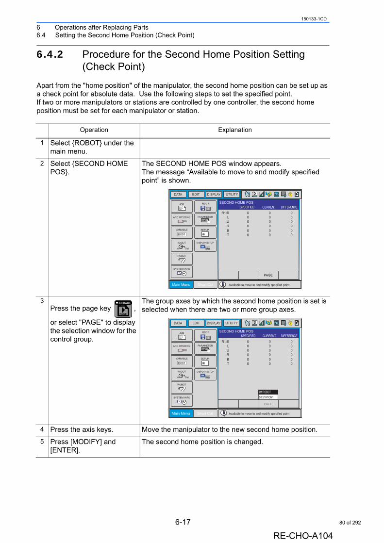
6 Operations after Replacing Parts6.4 Setting the Second Home Position (Check Point)
150133-1CD
6.4.2 Procedure for the Second Home Position Setting (Check Point)
Apart from the "home position" of the manipulator, the second home position can be set up as a check point for absolute data. Use the following steps to set the specified point. If two or more manipulators or stations are controlled by one controller, the second home position must be set for each manipulator or station.
Operation Explanation
1 Select {ROBOT} under the main menu.
2 Select {SECOND HOME POS}.
The SECOND HOME POS window appears.The message “Available to move to and modify specified point” is shown.
3Press the page key ,
or select "PAGE" to display the selection window for the control group.
The group axes by which the second home position is set is selected when there are two or more group axes.
4 Press the axis keys. Move the manipulator to the new second home position.
5 Press [MODIFY] and [ENTER].
The second home position is changed.
Main Menu Short Cut
JOBDOUTMOVEEND
IN/OUT
In Out
SYSTEM INFO
ARC WELDING
VARIABLE
B001
ROBOT
CF
FD/CF
SETUP
PARAMETER
DISPLAY SETUP
Aa
DATA EDIT DISPLAY UTILITY T
PAGE
R1:SLURBT
0 0 00 0 00 0 00 0 00 0 00 0 0
SECOND HOME POSSPECIFIED CURRENT DIFFERENCE
Available to move to and modify specified point
PAGE
GO BACK
Main Menu Short Cut
JOBDOUTMOVEEND
IN/OUT
In Out
SYSTEM INFO
ARC WELDING
VARIABLE
B001
ROBOT
CF
FD/CF
SETUP
PARAMETER
DISPLAY SETUP
Aa
DATA EDIT DISPLAY UTILITY T
PAGE
R1:SLURBT
0 0 00 0 00 0 00 0 00 0 00 0 0
SECOND HOME POSSPECIFIED CURRENT DIFFERENCE
S1:STATION1R1:ROBOT
Available to move to and modify specified point
6-17
RE-CHO-A104
80 of 292
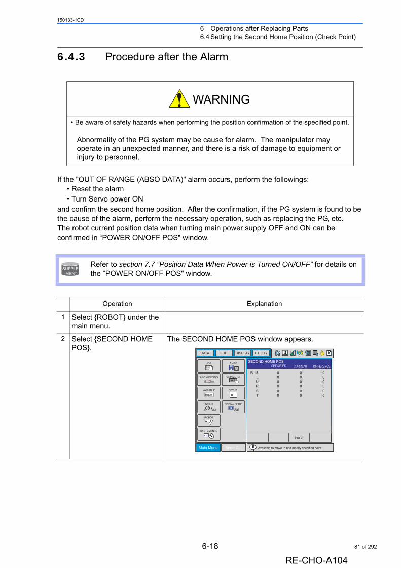
6 Operations after Replacing Parts6.4 Setting the Second Home Position (Check Point)
150133-1CD
6.4.3 Procedure after the Alarm
If the "OUT OF RANGE (ABSO DATA)" alarm occurs, perform the followings: • Reset the alarm• Turn Servo power ON
and confirm the second home position. After the confirmation, if the PG system is found to be the cause of the alarm, perform the necessary operation, such as replacing the PG, etc.The robot current position data when turning main power supply OFF and ON can be confirmed in “POWER ON/OFF POS" window.
• Be aware of safety hazards when performing the position confirmation of the specified point.
Abnormality of the PG system may be cause for alarm. The manipulator may operate in an unexpected manner, and there is a risk of damage to equipment or injury to personnel.
Refer to section 7.7 “Position Data When Power is Turned ON/OFF” for details on the “POWER ON/OFF POS" window.
Operation Explanation
1 Select {ROBOT} under the main menu.
2 Select {SECOND HOME POS}.
The SECOND HOME POS window appears.
SUPPLE-MENT
Main Menu Short Cut
JOBDOUTMOVEEND
IN/OUT
In Out
SYSTEM INFO
ARC WELDING
VARIABLE
B001
ROBOT
CF
FD/CF
SETUP
PARAMETER
DISPLAY SETUP
Aa
DATA EDIT DISPLAY UTILITY T
PAGE
R1:SLURBT
0 0 00 0 00 0 00 0 00 0 00 0 0
SECOND HOME POSSPECIFIED CURRENT DIFFERENCE
Available to move to and modify specified point
6-18
RE-CHO-A104
81 of 292
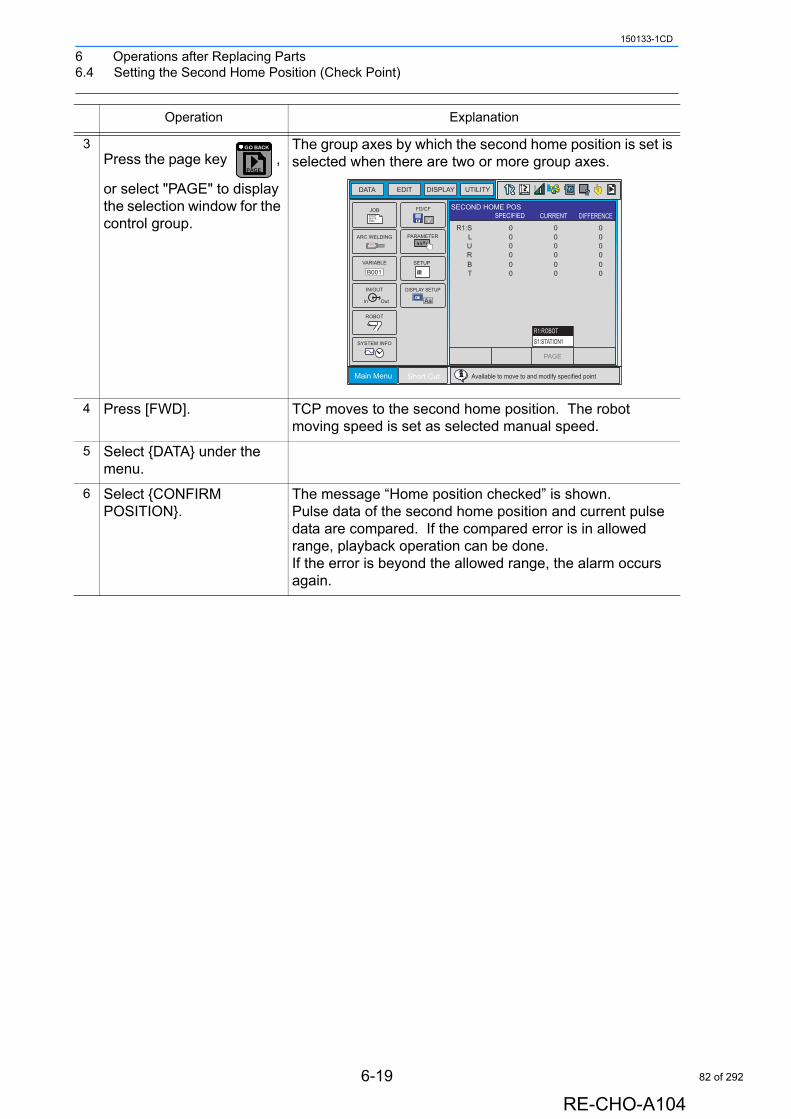
6 Operations after Replacing Parts6.4 Setting the Second Home Position (Check Point)
150133-1CD
3Press the page key ,
or select "PAGE" to display the selection window for the control group.
The group axes by which the second home position is set is selected when there are two or more group axes.
4 Press [FWD]. TCP moves to the second home position. The robot moving speed is set as selected manual speed.
5 Select {DATA} under the menu.
6 Select {CONFIRM POSITION}.
The message “Home position checked” is shown.Pulse data of the second home position and current pulse data are compared. If the compared error is in allowed range, playback operation can be done.If the error is beyond the allowed range, the alarm occurs again.
Operation Explanation
PAGE
GO BACK
Main Menu Short Cut
JOBDOUTMOVEEND
IN/OUT
In Out
SYSTEM INFO
ARC WELDING
VARIABLE
B001
ROBOT
CF
FD/CF
SETUP
PARAMETER
DISPLAY SETUP
Aa
DATA EDIT DISPLAY UTILITY T
PAGE
R1:SLURBT
0 0 00 0 00 0 00 0 00 0 00 0 0
SECOND HOME POSSPECIFIED CURRENT DIFFERENCE
S1:STATION1R1:ROBOT
Available to move to and modify specified point
6-19
RE-CHO-A104
82 of 292
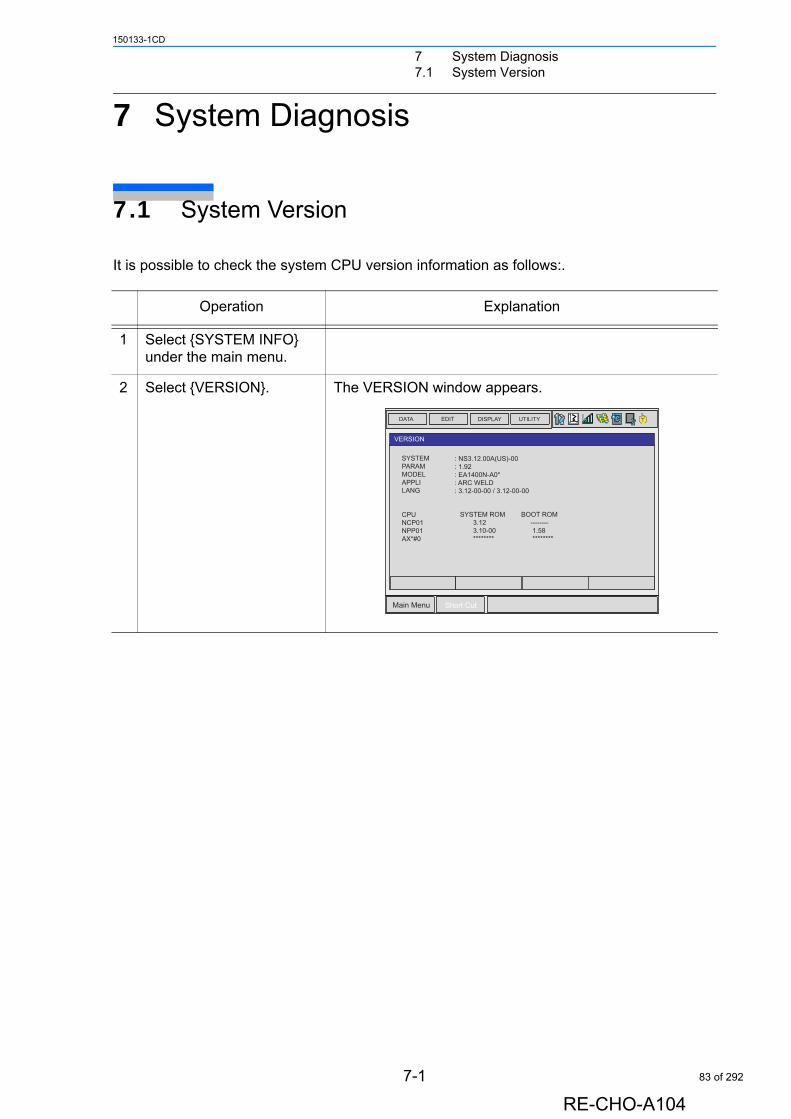
7 System Diagnosis7.1 System Version
150133-1CD
7 System Diagnosis
7.1 System Version
It is possible to check the system CPU version information as follows:.
Operation Explanation
1 Select {SYSTEM INFO} under the main menu.
2 Select {VERSION}. The VERSION window appears.
DATA EDIT DISPLAY UTILITY
Main Menu Short Cut
VERSION
SYSTEM ROM 3.12� 3.10-00 ********
BOOT ROM -------- 1.58 ********
SYSTEMPARAMMODELAPPLILANG
CPUNCP01NPP01AX*#0
: NS3.12.00A(US)-00: 1.92: EA1400N-A0*: ARC WELD: 3.12-00-00 / 3.12-00-00
T
7-1
RE-CHO-A104
83 of 292
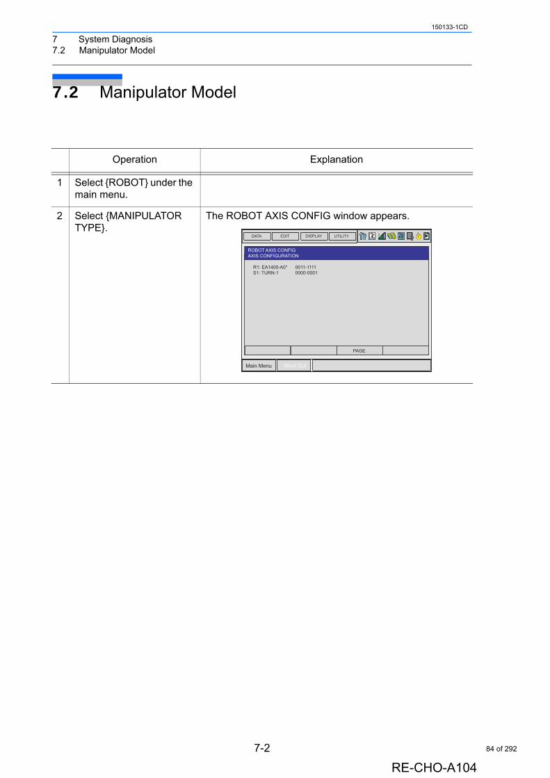
7 System Diagnosis7.2 Manipulator Model
150133-1CD
7.2 Manipulator Model
Operation Explanation
1 Select {ROBOT} under the main menu.
2 Select {MANIPULATOR TYPE}.
The ROBOT AXIS CONFIG window appears.
DATA EDIT DISPLAY UTILITY
Main Menu Short Cut
T
ROBOT AXIS CONFIGAXIS CONFIGURATION
R1: EA1400-A0*S1: TURN-1
0011-11110000-0001
PAGE
7-2
RE-CHO-A104
84 of 292
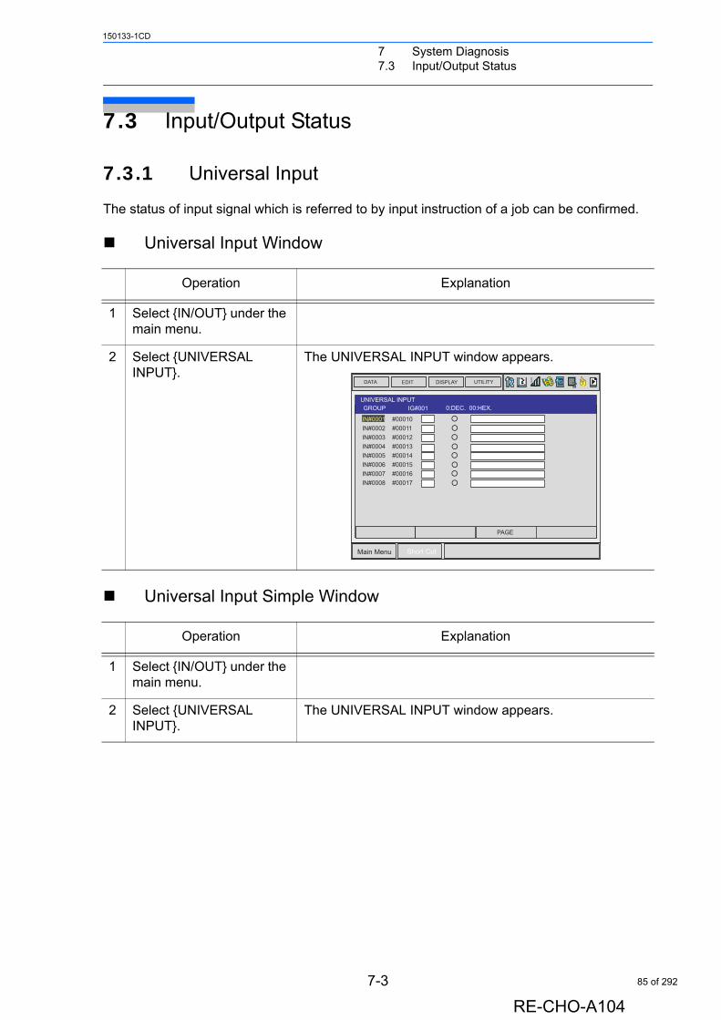
7 System Diagnosis7.3 Input/Output Status
150133-1CD
7.3 Input/Output Status
7.3.1 Universal Input
The status of input signal which is referred to by input instruction of a job can be confirmed.
Universal Input Window
Universal Input Simple Window
Operation Explanation
1 Select {IN/OUT} under the main menu.
2 Select {UNIVERSAL INPUT}.
The UNIVERSAL INPUT window appears.
Operation Explanation
1 Select {IN/OUT} under the main menu.
2 Select {UNIVERSAL INPUT}.
The UNIVERSAL INPUT window appears.
DATA EDIT DISPLAY UTILITY
Main Menu Short Cut
T
PAGE
UNIVERSAL INPUTGROUP IG#001 0:DEC. 00:HEX.
IN#0001 #00010
IN#0002 #00011IN#0003 #00012IN#0004 #00013IN#0005 #00014IN#0006 #00015IN#0007 #00016IN#0008 #00017
7-3
RE-CHO-A104
85 of 292

7 System Diagnosis7.3 Input/Output Status
150133-1CD
2 Select {SIMPLE} from the pull-down menu of {DISPLAY}.
The UNIVERSAL INPUT simple window appears.
Operation Explanation
DATA EDIT DISPLAY UTILITY
Main Menu Short Cut
T
UNIVERSAL INPUTNO. 7654_3210
0000_0000�0000_0000�0000_0000�0000_0000�0000_0000�0000_0000�0000_0000�0000_00000000_00000000_00000000_00000000_00000000_0000
#0001X#0002X�#0003X�#0004X�#0005X�#0006X�#0007X�#0008X#0009X#0010X#0011X#0012X#0013X
7-4
RE-CHO-A104
86 of 292
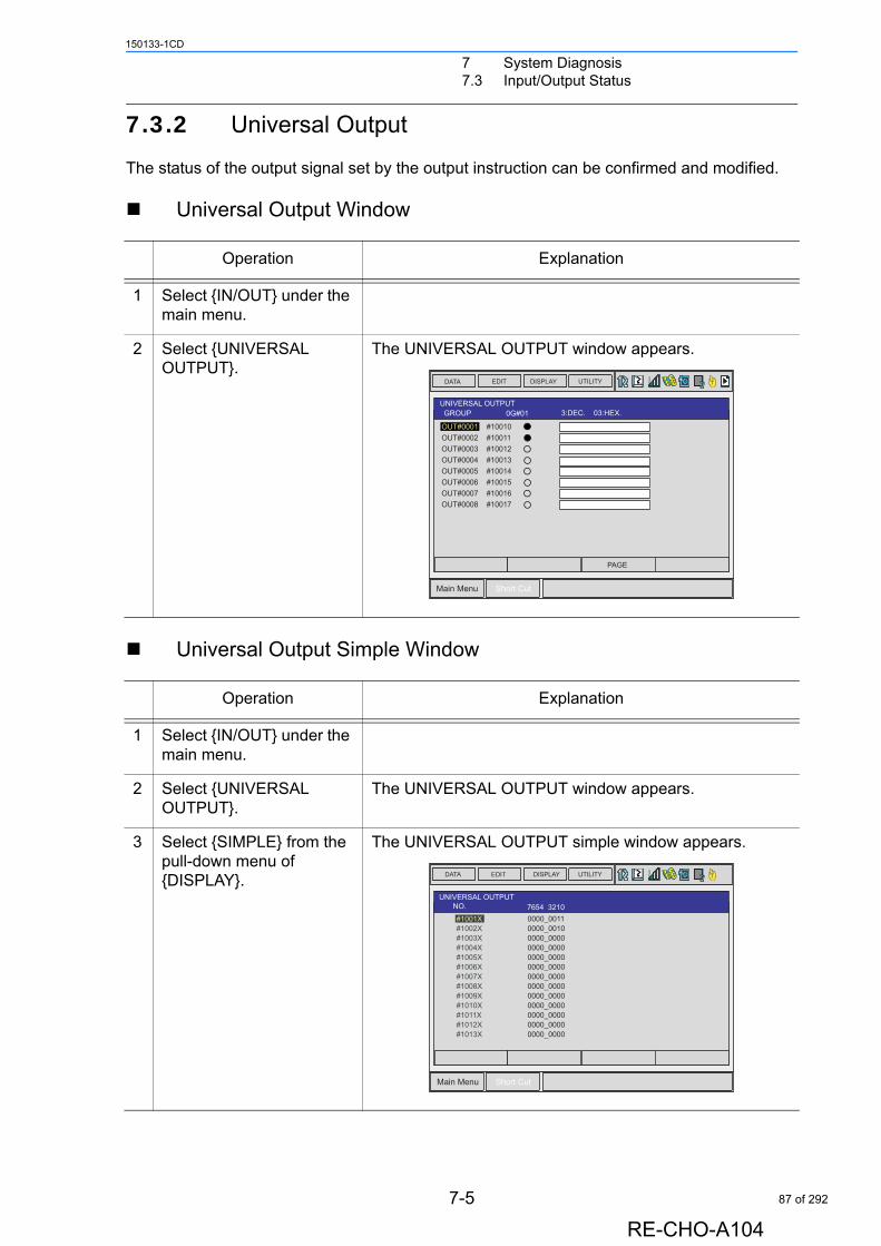
7 System Diagnosis7.3 Input/Output Status
150133-1CD
7.3.2 Universal Output
The status of the output signal set by the output instruction can be confirmed and modified.
Universal Output Window
Universal Output Simple Window
Operation Explanation
1 Select {IN/OUT} under the main menu.
2 Select {UNIVERSAL OUTPUT}.
The UNIVERSAL OUTPUT window appears.
Operation Explanation
1 Select {IN/OUT} under the main menu.
2 Select {UNIVERSAL OUTPUT}.
The UNIVERSAL OUTPUT window appears.
3 Select {SIMPLE} from the pull-down menu of {DISPLAY}.
The UNIVERSAL OUTPUT simple window appears.
DATA EDIT DISPLAY UTILITY
Main Menu Short Cut
T
PAGE
UNIVERSAL OUTPUTGROUP 0G#01 3:DEC. 03:HEX.
OUT#0001 #10010OUT#0002 #10011OUT#0003 #10012OUT#0004 #10013OUT#0005 #10014OUT#0006 #10015OUT#0007 #10016OUT#0008 #10017
DATA EDIT DISPLAY UTILITY
Main Menu Short Cut
T
UNIVERSAL OUTPUTNO. 7654_3210
0000_0011�0000_0010�0000_00000000_00000000_00000000_00000000_00000000_00000000_00000000_00000000_00000000_00000000_0000
#1001X#1002X�#1003X�#1004X�#1005X�#1006X�#1007X�#1008X#1009X#1010X#1011X#1012X#1013X
7-5
RE-CHO-A104
87 of 292
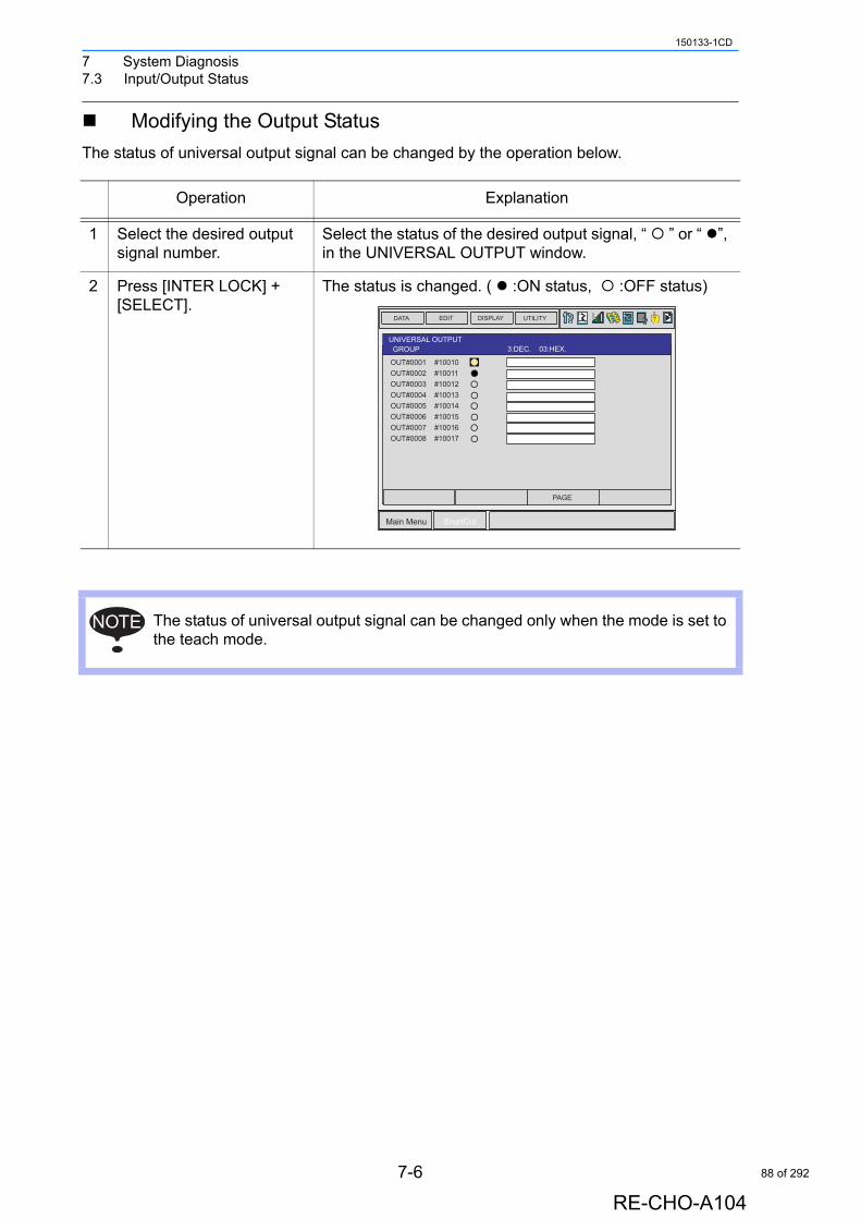
7 System Diagnosis7.3 Input/Output Status
150133-1CD
Modifying the Output Status
The status of universal output signal can be changed by the operation below.
Operation Explanation
1 Select the desired output signal number.
Select the status of the desired output signal, “ ” or “ ”, in the UNIVERSAL OUTPUT window.
2 Press [INTER LOCK] + [SELECT].
The status is changed. ( :ON status, :OFF status)
The status of universal output signal can be changed only when the mode is set to the teach mode.
DATA EDIT DISPLAY UTILITY
Main Menu ShortCut
T
PAGE
UNIVERSAL OUTPUTGROUP 3:DEC. 03:HEX.
OUT#0001 #10010OUT#0002 #10011OUT#0003 #10012OUT#0004 #10013OUT#0005 #10014OUT#0006 #10015OUT#0007 #10016OUT#0008 #10017
NOTE
7-6
RE-CHO-A104
88 of 292
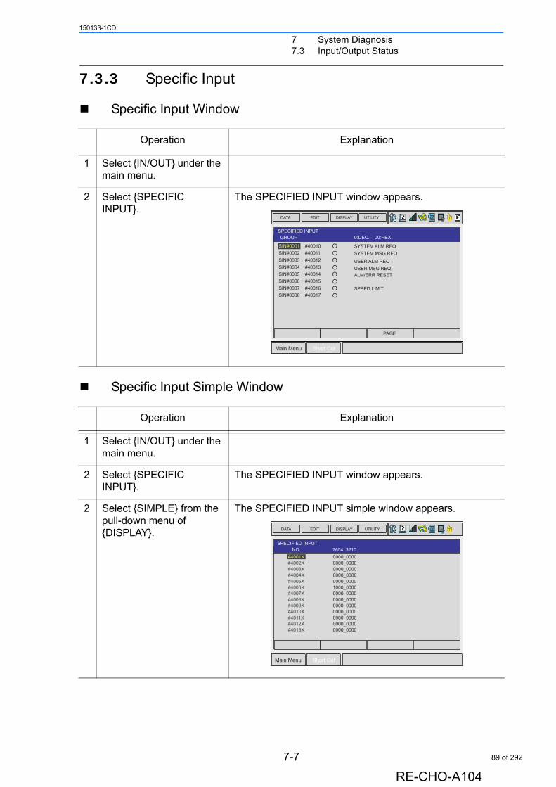
7 System Diagnosis7.3 Input/Output Status
150133-1CD
7.3.3 Specific Input
Specific Input Window
Specific Input Simple Window
Operation Explanation
1 Select {IN/OUT} under the main menu.
2 Select {SPECIFIC INPUT}.
The SPECIFIED INPUT window appears.
Operation Explanation
1 Select {IN/OUT} under the main menu.
2 Select {SPECIFIC INPUT}.
The SPECIFIED INPUT window appears.
2 Select {SIMPLE} from the pull-down menu of {DISPLAY}.
The SPECIFIED INPUT simple window appears.
DATA EDIT DISPLAY UTILITY
Main Menu Short Cut
T
PAGE
SPECIFIED INPUTGROUP 0:DEC. 00:HEX.
SYSTEM ALM REQ
SYSTEM MSG REQUSER ALM REQUSER MSG REQALM/ERR RESET
SPEED LIMIT
SIN#0001 #40010SIN#0002 #40011SIN#0003 #40012SIN#0004 #40013SIN#0005 #40014SIN#0006 #40015SIN#0007 #40016SIN#0008 #40017
DATA EDIT DISPLAY UTILITY
Main Menu Short Cut
T
0000_0000�0000_0000�0000_00000000_00000000_00001000_00000000_00000000_00000000_00000000_00000000_00000000_00000000_0000
#4001X#4002X�#4003X�#4004X�#4005X�#4006X�#4007X�#4008X#4009X#4010X#4011X#4012X#4013X
SPECIFIED INPUTNO. 7654_3210
7-7
RE-CHO-A104
89 of 292
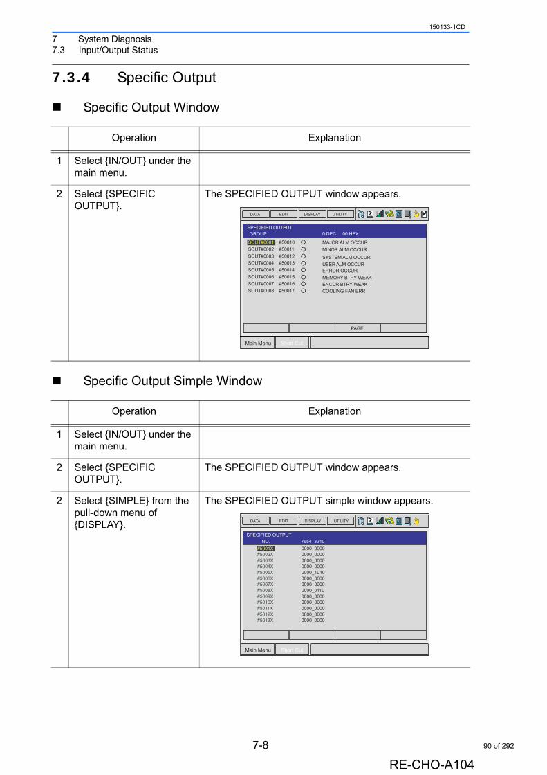
7 System Diagnosis7.3 Input/Output Status
150133-1CD
7.3.4 Specific Output
Specific Output Window
Specific Output Simple Window
Operation Explanation
1 Select {IN/OUT} under the main menu.
2 Select {SPECIFIC OUTPUT}.
The SPECIFIED OUTPUT window appears.
Operation Explanation
1 Select {IN/OUT} under the main menu.
2 Select {SPECIFIC OUTPUT}.
The SPECIFIED OUTPUT window appears.
2 Select {SIMPLE} from the pull-down menu of {DISPLAY}.
The SPECIFIED OUTPUT simple window appears.
DATA EDIT DISPLAY UTILITY
Main Menu Short Cut
T
PAGE
0:DEC. 00:HEX.SPECIFIED OUTPUTGROUP
SOUT#0001 #50010SOUT#0002 #50011SOUT#0003 #50012SOUT#0004 #50013SOUT#0005 #50014SOUT#0006 #50015SOUT#0007 #50016SOUT#0008 #50017
MAJOR ALM OCCUR
MINOR ALM OCCURSYSTEM ALM OCCURUSER ALM OCCURERROR OCCURMEMORY BTRY WEAKENCDR BTRY WEAKCOOLING FAN ERR
DATA EDIT DISPLAY UTILITY
Main Menu Short Cut
T
0000_0000�0000_0000�0000_00000000_00000000_10100000_00000000_00000000_01100000_00000000_00000000_00000000_00000000_0000
#5001X#5002X�#5003X�#5004X�#5005X�#5006X�#5007X�#5008X#5009X#5010X#5011X#5012X#5013X
SPECIFIED OUTPUTNO. 7654_3210
7-8
RE-CHO-A104
90 of 292
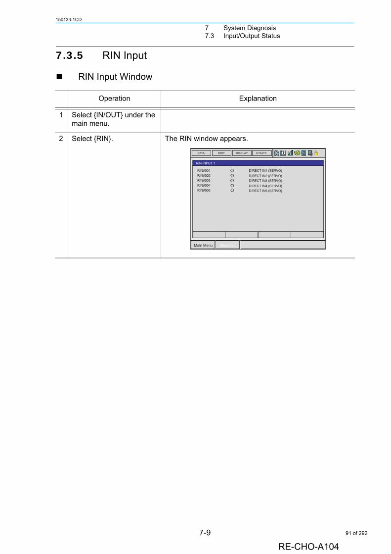
7 System Diagnosis7.3 Input/Output Status
150133-1CD
7.3.5 RIN Input
RIN Input Window
Operation Explanation
1 Select {IN/OUT} under the main menu.
2 Select {RIN}. The RIN window appears.
DATA EDIT DISPLAY UTILITY
Main Menu Short Cut
T
RIN INPUT 1
RIN#001RIN#002RIN#003RIN#004RIN#005
DIRECT IN1 (SERVO)
DIRECT IN2 (SERVO)DIRECT IN3 (SERVO)DIRECT IN4 (SERVO)DIRECT IN5 (SERVO)
7-9
RE-CHO-A104
91 of 292
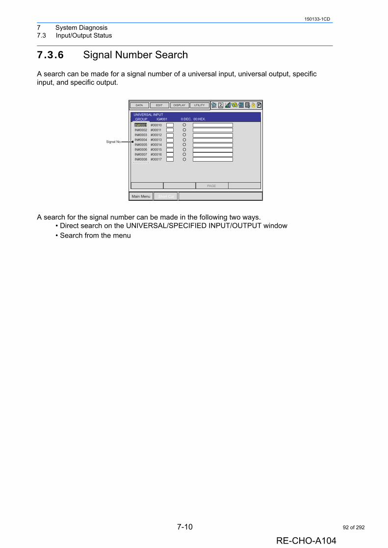
7 System Diagnosis7.3 Input/Output Status
150133-1CD
7.3.6 Signal Number Search
A search can be made for a signal number of a universal input, universal output, specific input, and specific output.
A search for the signal number can be made in the following two ways.• Direct search on the UNIVERSAL/SPECIFIED INPUT/OUTPUT window• Search from the menu
IG#01 123 : 10 7b : 16
DATA EDIT DISPLAY UTILITY
Main Menu Short Cut
T
PAGE
UNIVERSAL INPUTGROUP IG#001 0:DEC. 00:HEX.
IN#0001 #00010
IN#0002 #00011IN#0003 #00012IN#0004 #00013IN#0005 #00014IN#0006 #00015IN#0007 #00016IN#0008 #00017
Signal No.
7-10
RE-CHO-A104
92 of 292
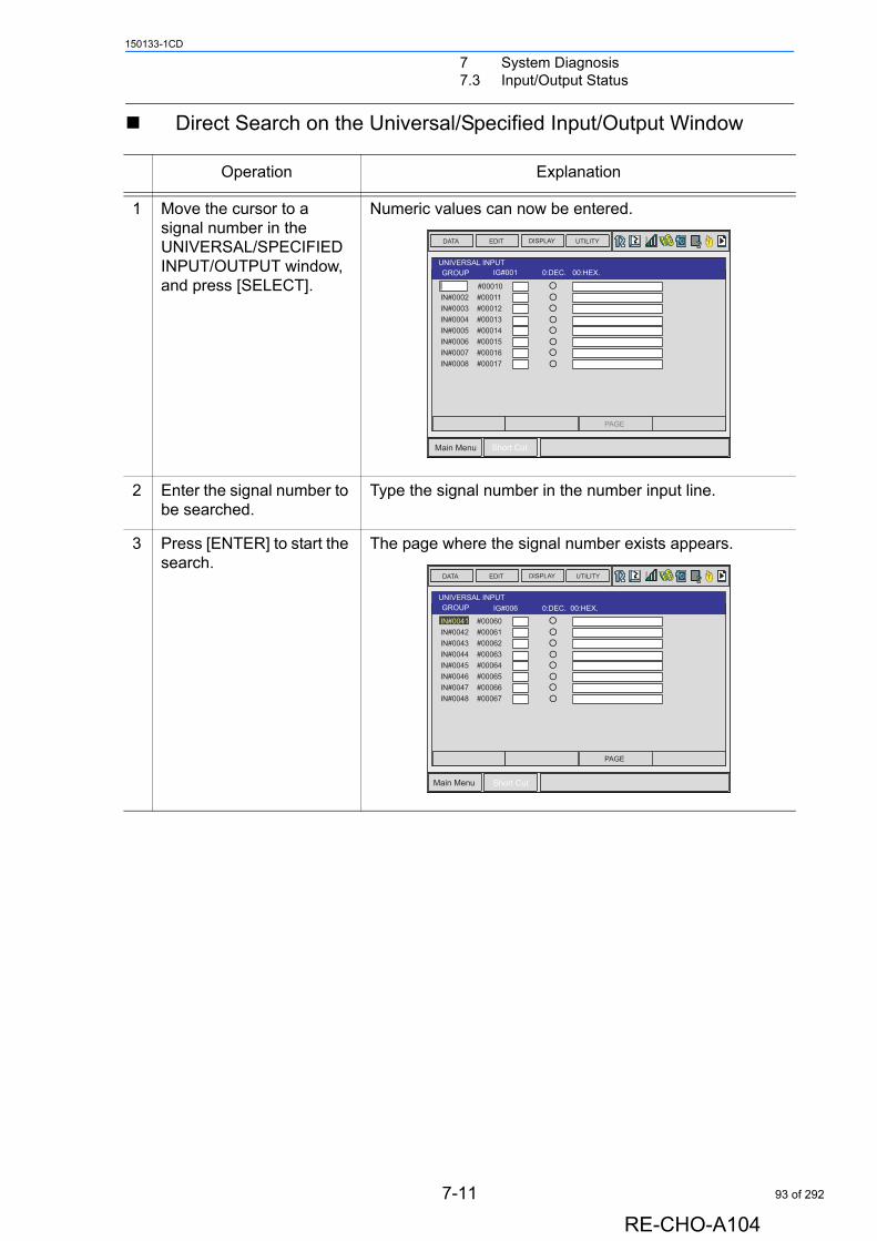
7 System Diagnosis7.3 Input/Output Status
150133-1CD
Direct Search on the Universal/Specified Input/Output Window
Operation Explanation
1 Move the cursor to a signal number in the UNIVERSAL/SPECIFIED INPUT/OUTPUT window, and press [SELECT].
Numeric values can now be entered.
2 Enter the signal number to be searched.
Type the signal number in the number input line.
3 Press [ENTER] to start the search.
The page where the signal number exists appears.
IG#01 123 : 10 7b : 16
DATA EDIT DISPLAY UTILITY
Main Menu Short Cut
T
PAGE
UNIVERSAL INPUTGROUP IG#001 0:DEC. 00:HEX.
#00010
IN#0002 #00011IN#0003 #00012IN#0004 #00013IN#0005 #00014IN#0006 #00015IN#0007 #00016IN#0008 #00017
IG#01 123 : 10 7b : 16
DATA EDIT DISPLAY UTILITY
Main Menu Short Cut
T
PAGE
UNIVERSAL INPUTGROUP IG#006 0:DEC. 00:HEX.
IN#0041 #00060
IN#0042 #00061IN#0043 #00062IN#0044 #00063IN#0045 #00064IN#0046 #00065IN#0047 #00066IN#0048 #00067
7-11
RE-CHO-A104
93 of 292

7 System Diagnosis7.3 Input/Output Status
150133-1CD
Search from the Menu
Operation Explanation
1 Select {EDIT} under the menu in the UNIVERSAL/SPECIFIED INPUT/OUTPUT window.
The pull-down menu appears.
2 Select {SEARCH SIGNAL NO.}.
Numeric values can now be entered.
3 Enter the signal number to be searched.
Type the signal number in the number input line.
4 Press [ENTER] to start the search.
The page where the signal number exists appears.
EDI
IG#01 123 : 10 7b : 16
DATA EDIT DISPLAY UTILITY
Main Menu Short Cut
T
PAGE
UNIVERSAL INPUTGROUP IG#001 0:DEC. 00:HEX.
IN#0001 #00010
IN#0002 #00011IN#0003 #00012IN#0004 #00013IN#0005 #00014IN#0006 #00015IN#0007 #00016IN#0008 #00017
SEARCH SIGNALNO.
SEARCH RELAYNO.
SELECT ALL SIM
SELECT ALL PHY
RENAME
IG#01 123 : 10 7b : 16
DATA EDIT DISPLAY UTILITY
Main Menu Short Cut
T
PAGE
UNIVERSAL INPUTGROUP IG#001 0:DEC. 00:HEX.
#00010
IN#0002 #00011IN#0003 #00012IN#0004 #00013IN#0005 #00014IN#0006 #00015IN#0007 #00016IN#0008 #00017
7-12
RE-CHO-A104
94 of 292
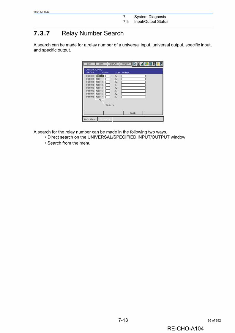
7 System Diagnosis7.3 Input/Output Status
150133-1CD
7.3.7 Relay Number Search
A search can be made for a relay number of a universal input, universal output, specific input, and specific output.
A search for the relay number can be made in the following two ways.• Direct search on the UNIVERSAL/SPECIFIED INPUT/OUTPUT window• Search from the menu
IG#01 123 : 10 7b : 16
DATA EDIT DISPLAY UTILITY
Main Menu Short Cut
T
PAGE
UNIVERSAL INPUTGROUP IG#001 0:DEC. 00:HEX.
IN#0001 #00010
IN#0002 #00011IN#0003 #00012IN#0004 #00013IN#0005 #00014IN#0006 #00015IN#0007 #00016IN#0008 #00017
Relay No.Relay No.
7-13
RE-CHO-A104
95 of 292
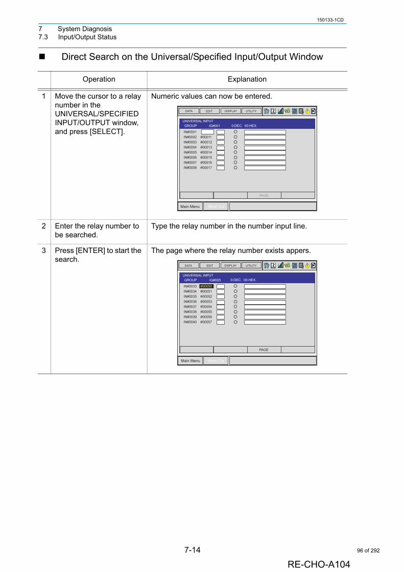
7 System Diagnosis7.3 Input/Output Status
150133-1CD
Direct Search on the Universal/Specified Input/Output Window
Operation Explanation
1 Move the cursor to a relay number in the UNIVERSAL/SPECIFIED INPUT/OUTPUT window, and press [SELECT].
Numeric values can now be entered.
2 Enter the relay number to be searched.
Type the relay number in the number input line.
3 Press [ENTER] to start the search.
The page where the relay number exists appers.
IG#01 123 : 10 7b : 16
DATA EDIT DISPLAY UTILITY
Main Menu Short Cut
T
PAGE
UNIVERSAL INPUTGROUP IG#001 0:DEC. 00:HEX.
IN#0001
IN#0002 #00011IN#0003 #00012IN#0004 #00013IN#0005 #00014IN#0006 #00015IN#0007 #00016IN#0008 #00017
IG#01 123 : 10 7b : 16
DATA EDIT DISPLAY UTILITY
Main Menu Short Cut
T
PAGE
UNIVERSAL INPUTGROUP IG#005 0:DEC. 00:HEX.
IN#0033 #00050
IN#0034 #00051IN#0035 #00052IN#0036 #00053IN#0037 #00054IN#0038 #00055IN#0039 #00056IN#0040 #00057
7-14
RE-CHO-A104
96 of 292

7 System Diagnosis7.3 Input/Output Status
150133-1CD
Search from the Menu
Operation Explanation
1 Select {EDIT} under the menu in the UNIVERSAL/SPECIFIED INPUT/OUTPUT window.
The pull-down menu appears.
2 Select {SEARCH RELAY SIGNAL NO.}.
Numeric values can now be entered.
3 Enter the relay number to be searched.
Type the relay number in the number input line.
4 Press [ENTER] to start the search.
The page where the relay number exists appears.
IG#01 123 : 10 7b : 16
DATA EDIT DISPLAY UTILITY
Main Menu Short Cut
T
PAGE
UNIVERSAL INPUTGROUP IG#001 0:DEC. 00:HEX.
IN#0001 #00010
IN#0002 #00011IN#0003 #00012IN#0004 #00013IN#0005 #00014IN#0006 #00015IN#0007 #00016IN#0008 #00017
SEARCH SIGNALNO.
SEARCH RELAYNO.
SELECT ALL SIM
SELECT ALL PHY
RENAME
IG#01 123 : 10 7b : 16
DATA EDIT DISPLAY UTILITY
Main Menu Short Cut
T
PAGE
UNIVERSAL INPUTGROUP IG#001 0:DEC. 00:HEX.
IN#0001
IN#0002 #00011IN#0003 #00012IN#0004 #00013IN#0005 #00014IN#0006 #00015IN#0007 #00016IN#0008 #00017
7-15
RE-CHO-A104
97 of 292
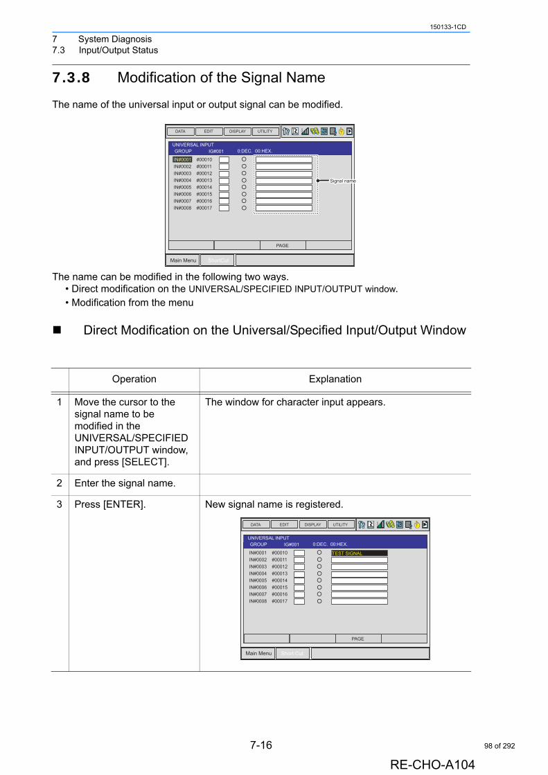
7 System Diagnosis7.3 Input/Output Status
150133-1CD
7.3.8 Modification of the Signal Name
The name of the universal input or output signal can be modified.
The name can be modified in the following two ways.• Direct modification on the UNIVERSAL/SPECIFIED INPUT/OUTPUT window.• Modification from the menu
Direct Modification on the Universal/Specified Input/Output Window
Operation Explanation
1 Move the cursor to the signal name to be modified in the UNIVERSAL/SPECIFIED INPUT/OUTPUT window, and press [SELECT].
The window for character input appears.
2 Enter the signal name.
3 Press [ENTER]. New signal name is registered.
IG#01 123 : 10 7b : 16
DATA EDIT DISPLAY UTILITY
Main Menu ShortCut
T
PAGE
UNIVERSAL INPUTGROUP IG#001 0:DEC. 00:HEX.
IN#0001 #00010
IN#0002 #00011IN#0003 #00012IN#0004 #00013IN#0005 #00014IN#0006 #00015IN#0007 #00016IN#0008 #00017
Signal nameSignal name
IG#01 123 : 10 7b : 16
DATA EDIT DISPLAY UTILITY
Main Menu Short Cut
T
PAGE
UNIVERSAL INPUTGROUP IG#001 0:DEC. 00:HEX.
IN#0001 #00010
IN#0002 #00011IN#0003 #00012IN#0004 #00013IN#0005 #00014IN#0006 #00015IN#0007 #00016IN#0008 #00017
TEST SIGNAL
7-16
RE-CHO-A104
98 of 292

7 System Diagnosis7.3 Input/Output Status
150133-1CD
Modification from the Menu
Operation Explanation
1 Move the cursor to the signal name to be modified in the UNIVERSAL/SPECIFIED INPUT/OUTPUT window.
2 Select {EDIT} under the menu.
The pull-down menu appears.
3 Select {RENAME}. The window for character input appears.
4 Enter the signal name.
5 Press [ENTER]. New signal name is registered.
IG#01 123 : 10 7b : 16
DATA EDIT DISPLAY UTILITY
Main Menu Short Cut
T
PAGE
UNIVERSAL INPUTGROUP IG#001 0:DEC. 00:HEX.
IN#0001 #00010
IN#0002 #00011IN#0003 #00012IN#0004 #00013IN#0005 #00014IN#0006 #00015IN#0007 #00016IN#0008 #00017
TEST SIGNAL
SEARCH SIGNALNO.
SEARCH RELAYNO.
SELECT ALL SIM
SELECT ALL PHY
RENAME
IG#01 123 : 10 7b : 16
DATA EDIT DISPLAY UTILITY
Main Menu Short Cut
T
PAGE
UNIVERSAL INPUTGROUP IG#001 0:DEC. 00:HEX.
IN#0001 #00010
IN#0002 #00011IN#0003 #00012IN#0004 #00013IN#0005 #00014IN#0006 #00015IN#0007 #00016IN#0008 #00017
TEST SIGNAL
7-17
RE-CHO-A104
99 of 292
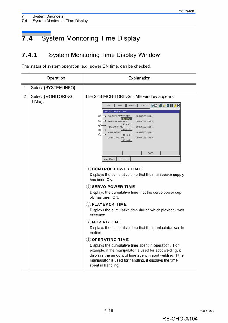
7 System Diagnosis7.4 System Monitoring Time Display
150133-1CD
7.4 System Monitoring Time Display
7.4.1 System Monitoring Time Display Window
The status of system operation, e.g. power ON time, can be checked.
Operation Explanation
1 Select {SYSTEM INFO}.
2 Select {MONITORING TIME}.
The SYS MONITORING TIME window appears.
CONTROL POWER TIMEDisplays the cumulative time that the main power supply has been ON.
SERVO POWER TIMEDisplays the cumulative time that the servo power sup-ply has been ON.
PLAYBACK TIMEDisplays the cumulative time during which playback was executed.
MOVING TIMEDisplays the cumulative time that the manipulator was in motion.
OPERATING TIMEDisplays the cumulative time spent in operation. For example, if the manipulator is used for spot welding, it displays the amount of time spent in spot welding; if the manipulator is used for handling, it displays the time spent in handling.
DATA EDIT DISPLAY UTILITY
Main Menu Short Cut
T
PAGE
SYS MONITORING TIME
1
2
3
4
5
1
2
3
4
5
1
2
3
4
5
7-18
RE-CHO-A104
100 of 292
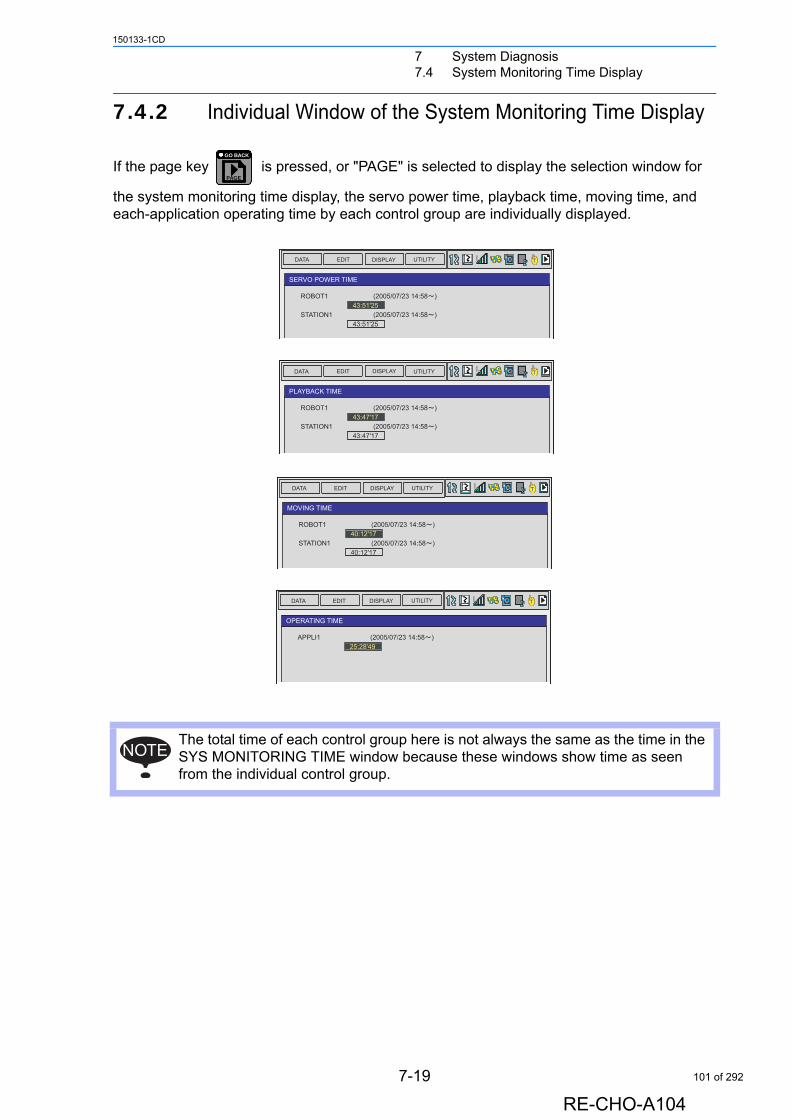
7 System Diagnosis7.4 System Monitoring Time Display
150133-1CD
7.4.2 Individual Window of the System Monitoring Time Display
If the page key is pressed, or "PAGE" is selected to display the selection window for
the system monitoring time display, the servo power time, playback time, moving time, and each-application operating time by each control group are individually displayed.
The total time of each control group here is not always the same as the time in the SYS MONITORING TIME window because these windows show time as seen from the individual control group.
PAGE
GO BACK
DATA EDIT DISPLAY UTILITY T
SERVO POWER TIME
DATA EDIT DISPLAY UTILITY T
PLAYBACK TIME
DATA EDIT DISPLAY UTILITY T
MOVING TIME
DATA EDIT DISPLAY UTILITY T
OPERATING TIME
NOTE
7-19
RE-CHO-A104
101 of 292
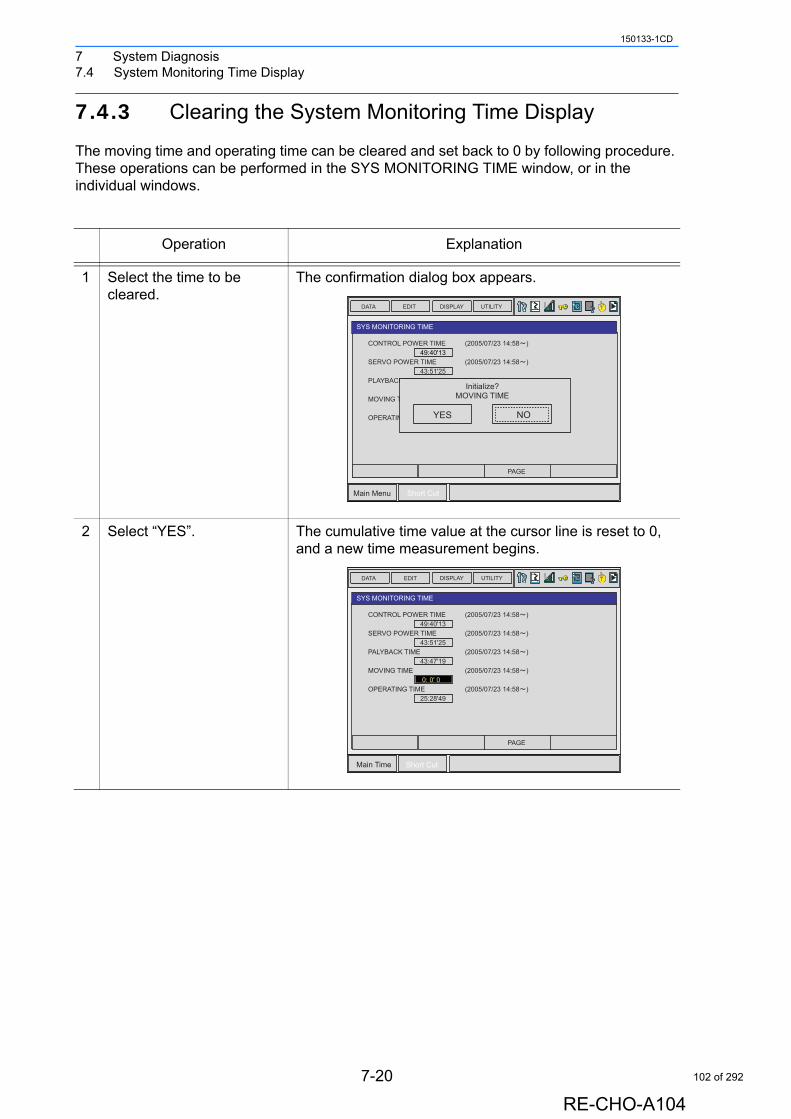
7 System Diagnosis7.4 System Monitoring Time Display
150133-1CD
7.4.3 Clearing the System Monitoring Time Display
The moving time and operating time can be cleared and set back to 0 by following procedure. These operations can be performed in the SYS MONITORING TIME window, or in the individual windows.
Operation Explanation
1 Select the time to be cleared.
The confirmation dialog box appears.
2 Select “YES”. The cumulative time value at the cursor line is reset to 0, and a new time measurement begins.
DATA EDIT DISPLAY UTILITY
Main Menu Short Cut
T
PAGE
SYS MONITORING TIME
YES NO
Initialize?MOVING TIME
DATA EDIT DISPLAY UTILITY
Main Time Short Cut
T
PAGE
SYS MONITORING TIME
7-20
RE-CHO-A104
102 of 292
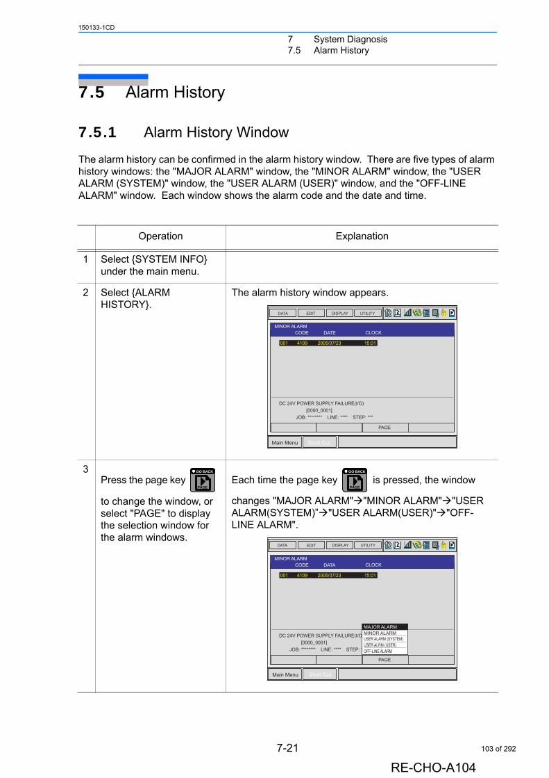
7 System Diagnosis7.5 Alarm History
150133-1CD
7.5 Alarm History
7.5.1 Alarm History Window
The alarm history can be confirmed in the alarm history window. There are five types of alarm history windows: the "MAJOR ALARM" window, the "MINOR ALARM" window, the "USER ALARM (SYSTEM)" window, the "USER ALARM (USER)" window, and the "OFF-LINE ALARM" window. Each window shows the alarm code and the date and time.
Operation Explanation
1 Select {SYSTEM INFO} under the main menu.
2 Select {ALARM HISTORY}.
The alarm history window appears.
3Press the page key
to change the window, or select "PAGE" to display the selection window for the alarm windows.
Each time the page key is pressed, the window
changes "MAJOR ALARM""MINOR ALARM""USER ALARM(SYSTEM)”"USER ALARM(USER)""OFF-LINE ALARM".
DATA EDIT DISPLAY UTILITY
Main Menu Short Cut
T
PAGE
MINOR ALARMCODE DATE CLOCK
DC 24V POWER SUPPLY FAILURE(I/O)� [0000_0001] JOB: ******** LINE: **** STEP: ***
001� 4109� 2005/07/23��� �15:01�
PAGE
GO BACK
PAGE
GO BACK
DATA EDIT DISPLAY UTILITY
Main Menu Short Cut
T
PAGE
MINOR ALARMCODE DATA CLOCK
DC 24V POWER SUPPLY FAILURE(I/O)� [0000_0001] JOB: ******** LINE: **** STEP: ***
001� 4109� 2005/07/23��� �15:01�
USER ALRM (USER)OFF-LINE ALARM
MINOR ALARMUSER ALARM (SYSTEM)
MAJOR ALARM
7-21
RE-CHO-A104
103 of 292
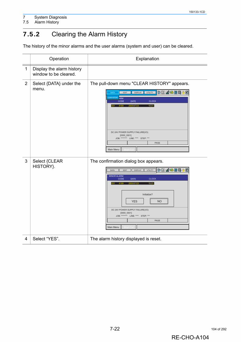
7 System Diagnosis7.5 Alarm History
150133-1CD
7.5.2 Clearing the Alarm History
The history of the minor alarms and the user alarms (system and user) can be cleared.
Operation Explanation
1 Display the alarm history window to be cleared.
2 Select {DATA} under the menu.
The pull-down menu "CLEAR HISTORY" appears.
3 Select {CLEAR HISTORY}.
The confirmation dialog box appears.
4 Select “YES”. The alarm history displayed is reset.
DATA EDIT DISPLAY UTILITY
Main Menu Short Cut
T
PAGE
MINOR ALARMCODE DATE CLOCK
001� 4109� 2005/07/23��� �15:01
CLEAR HISTORY
DC 24V POWER SUPPLY FAILURE(I/O)� [0000_0001] JOB: ******** LINE: **** STEP: ***
DATA EDIT DISPLAY UTILITY
Main Menu Short Cut
T
PAGE
MINOR ALARMCODE DATE CLOCK
001� 4109� 2005/07/23��� �15:01
YES NO
Initialize?
DC 24V POWER SUPPLY FAILURE(I/O)� [0000_0001] JOB: ******** LINE: **** STEP: ***
7-22
RE-CHO-A104
104 of 292

7 System Diagnosis7.6 I/O Message History
150133-1CD
7.6 I/O Message History
7.6.1 I/O Message History Window
The I/O message history can be confirmed in the I/O MESSAGE HISTORY window.The I/O MESSAGE HISTORY window shows the date and time, job name, line number, and step number of the I/O message that appeared on the window.
Search
Use the following operation to search for the I/O message history.
Operation Explanation
1 Select {SYSTEM INFO} under the main menu.
2 Select {I/O MSG HISTORY}.
The I/O MESSAGE HISTORY window appears.
Press [SELECT], and numeric values can now be entered. Input the history number, and press [ENTER]. The search for the input history number begins, and the I/O message that appeared on the window is displayed.
Operation Explanation
1 Select {EDIT} under the menu.
2 Select {SEARCH}. The character input line appears.
3 Enter the history No.
4 Press [ENTER]. The search for the input history number begins, and the I/O message is displayed.
DATA EDIT DISPLAY UTILITY
Main Menu Short Cut
I/O MESSAGE HISTORY
DATE:1999/06/16�12:00JOB NAME: ARCON LINE: 0006 STEP: 004
0001� GAS SHORTAGE0002� WIRE SHORTAGE00030004�0005�0006�0007
7-23
RE-CHO-A104
105 of 292
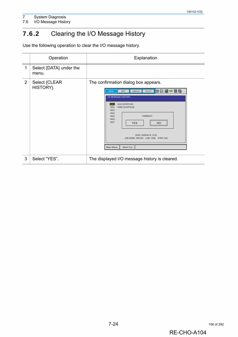
7 System Diagnosis7.6 I/O Message History
150133-1CD
7.6.2 Clearing the I/O Message History
Use the following operation to clear the I/O message history.
Operation Explanation
1 Select {DATA} under the menu.
2 Select {CLEAR HISTORY}.
The confirmation dialog box appears.
3 Select “YES”. The displayed I/O message history is cleared.
EDIT DISPLAY UTILITY
Main Menu Short Cut
I/O MESSAGE HISTORY
DATE:1999/06/16�12:00JOB NAME: ARCON LINE: 0006 STEP: 004
DATA
0001� GAS SHORTAGE0002� WIRE SHORTAGE00030004�0005�0006�0007 YES NO
Initialize?
7-24
RE-CHO-A104
106 of 292
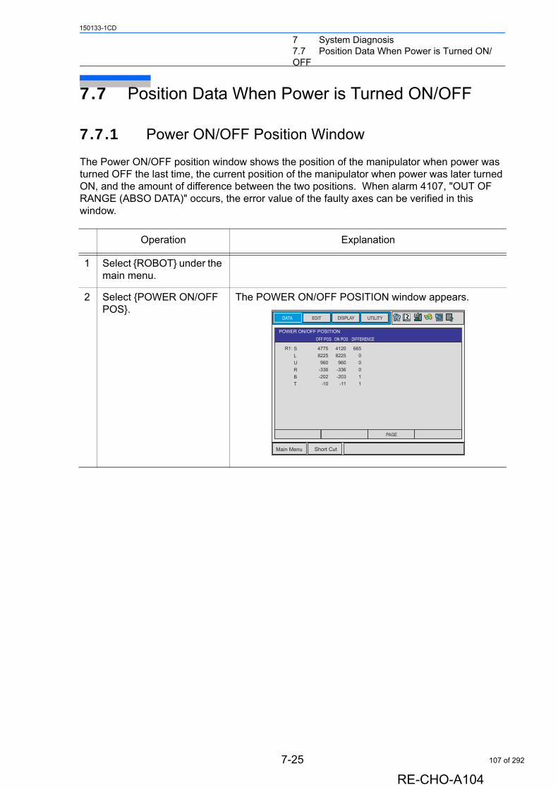
7 System Diagnosis7.7 Position Data When Power is Turned ON/
150133-1CD
OFF
7.7 Position Data When Power is Turned ON/OFF
7.7.1 Power ON/OFF Position Window
The Power ON/OFF position window shows the position of the manipulator when power was turned OFF the last time, the current position of the manipulator when power was later turned ON, and the amount of difference between the two positions. When alarm 4107, "OUT OF RANGE (ABSO DATA)" occurs, the error value of the faulty axes can be verified in this window.
Operation Explanation
1 Select {ROBOT} under the main menu.
2 Select {POWER ON/OFF POS}.
The POWER ON/OFF POSITION window appears.
DATA EDIT DISPLAY UTILITY
Main Menu Short Cut
POWER ON/OFF POSITIONOFF POS ON POS DIFFERENCE
41208225�
960�-336�-203�
-11
665�0�0�0�1�1
R1:
PAGE
SLURBT
47758225
960�-336-202
-10
7-25
RE-CHO-A104
107 of 292
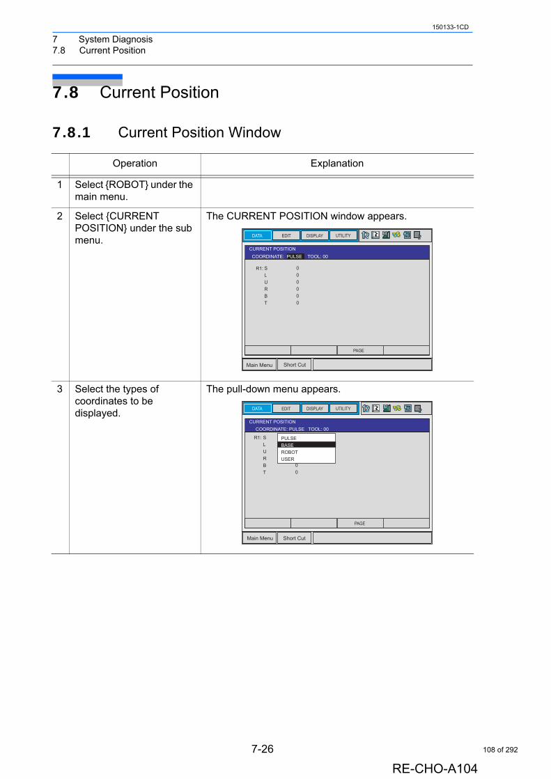
7 System Diagnosis7.8 Current Position
150133-1CD
7.8 Current Position
7.8.1 Current Position Window
Operation Explanation
1 Select {ROBOT} under the main menu.
2 Select {CURRENT POSITION} under the sub menu.
The CURRENT POSITION window appears.
3 Select the types of coordinates to be displayed.
The pull-down menu appears.
EDIT DISPLAY UTILITY
Main Menu Short Cut
CURRENT POSITIONTOOL: 00
R1:
COORDINATE: PULSE
DATA
PAGE
SLURBT
0�0�0�0�0�0
EDIT DISPLAY UTILITY
Main Menu Short Cut
CURRENT POSITION
R1: SLURBT
0�0�0�0�0�0
PULSEBASEROBOTUSER
TOOL: 00COORDINATE: PULSE
DATA
PAGE
7-26
RE-CHO-A104
108 of 292
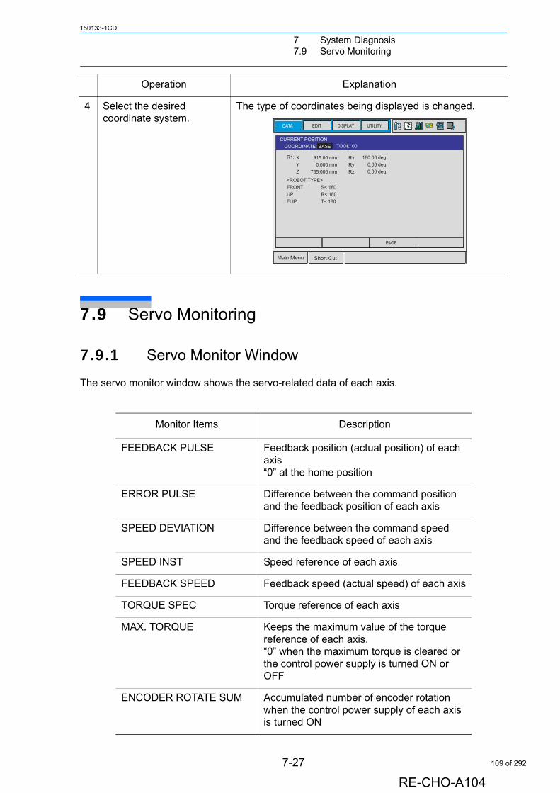
7 System Diagnosis7.9 Servo Monitoring
150133-1CD
7.9 Servo Monitoring
7.9.1 Servo Monitor Window
The servo monitor window shows the servo-related data of each axis.
4 Select the desired coordinate system.
The type of coordinates being displayed is changed.
Monitor Items Description
FEEDBACK PULSE Feedback position (actual position) of each axis“0” at the home position
ERROR PULSE Difference between the command position and the feedback position of each axis
SPEED DEVIATION Difference between the command speed and the feedback speed of each axis
SPEED INST Speed reference of each axis
FEEDBACK SPEED Feedback speed (actual speed) of each axis
TORQUE SPEC Torque reference of each axis
MAX. TORQUE Keeps the maximum value of the torque reference of each axis.“0” when the maximum torque is cleared or the control power supply is turned ON or OFF
ENCODER ROTATE SUM Accumulated number of encoder rotation when the control power supply of each axis is turned ON
Operation Explanation
EDIT DISPLAY UTILITY
Main Menu Short Cut
CURRENT POSITIONTOOL: 00
<ROBOT TYPE>�FRONT�� S< 180UP�� R< 180FLIP� T< 180
COORDINATE: BASE
DATA
PAGE
XYZ
915.00 mm0.000 mm
765.000 mm
RxRyRz
180.00 deg.0.00 deg.0.00 deg.
R1:
7-27
RE-CHO-A104
109 of 292
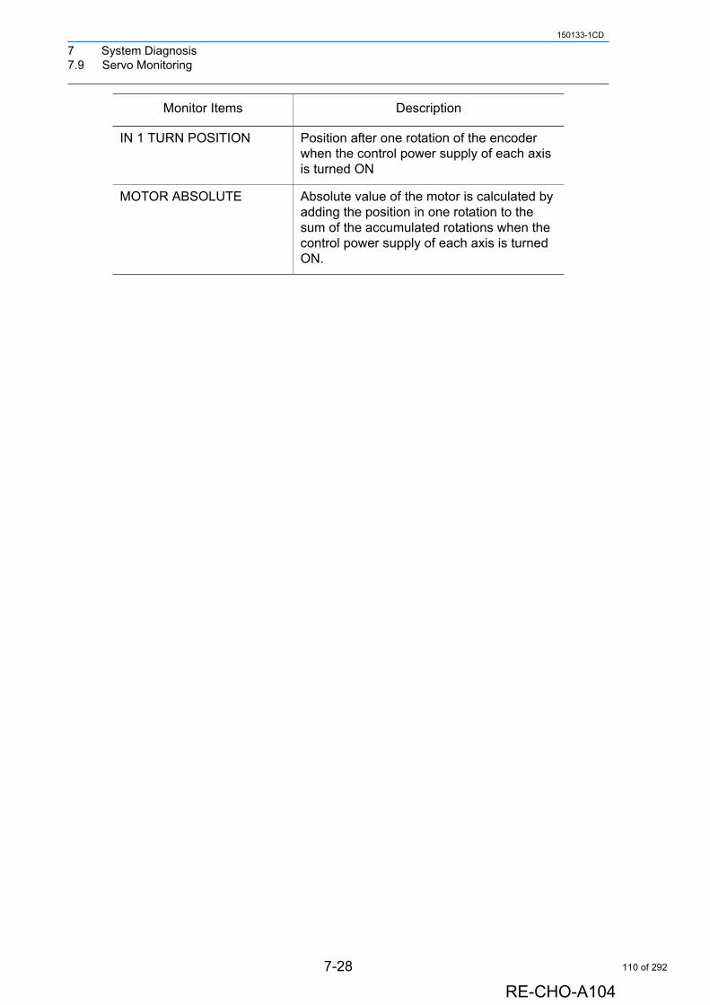
7 System Diagnosis7.9 Servo Monitoring
150133-1CD
IN 1 TURN POSITION Position after one rotation of the encoder when the control power supply of each axis is turned ON
MOTOR ABSOLUTE Absolute value of the motor is calculated by adding the position in one rotation to the sum of the accumulated rotations when the control power supply of each axis is turned ON.
Monitor Items Description
7-28
RE-CHO-A104
110 of 292
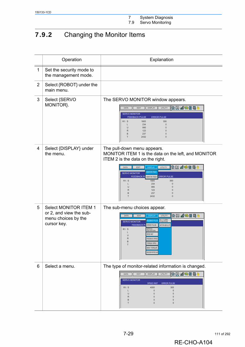
7 System Diagnosis7.9 Servo Monitoring
150133-1CD
7.9.2 Changing the Monitor Items
Operation Explanation
1 Set the security mode to the management mode.
2 Select {ROBOT} under the main menu.
3 Select {SERVO MONITOR}.
The SERVO MONITOR window appears.
4 Select {DISPLAY} under the menu.
The pull-down menu appears.MONITOR ITEM 1 is the data on the left, and MONITOR ITEM 2 is the data on the right.
5 Select MONITOR ITEM 1 or 2, and view the sub-menu choices by the cursor key.
The sub-menu choices appear.
6 Select a menu. The type of monitor-related information is changed.
DATA EDIT DISPLAY UTILITY T
SERVO MONITORFEEDBACK PULSE ERROR PULSE
S�� 1805� L�� 234� U� 995� R�� 123� B�� 237� T� 2432
300� 0� 0� 0� 0� 0
R1:
DATA EDIT DISPLAY UTILITY T
SERVO MONITORFEEDBACK PULSE ERROR PULSE
S��� 1805�L��� 234U��� 995R��� 123�B��� 237�T��� 2432
300� 0� 0� 0� 0� 0
MONITOR ITEM1>
MONITOR ITEM2>
R1:
R1:S��� 1805� L��� 234� U��� 995� R��� 123� B��� 237� T��� 2432
300� 0� 0� 0� 0� 0
1 >
2 >
DATA EDIT DISPLAY UTILITY T
SERVO MONITORFEEDBACK PULSE
S��� 1805�L��� 234�U��� 995�R��� 123�B��� 237�T��� 2432
300� 0� 0� 0� 0� 0
FEEDBACK PULSE
ERROR PULSE
IN 1 TURNPOSITION
MOTOR ABSOLUTE
SPEEDDEVIATION
SPEED INST
FEEDBACK SPEED
TORQUE SPEC
MAX TORQUE
ENCODER ROTATE SUM
R1:
DATA EDIT DISPLAY UTILITY T
SERVO MONITORERROR PULSESPEED INST
S��� 4000�L��� 0�U��� 0�R��� 0�B��� 0�T��� 0
300� 0� 0� 0� 0� 0
R1:
7-29
RE-CHO-A104
111 of 292
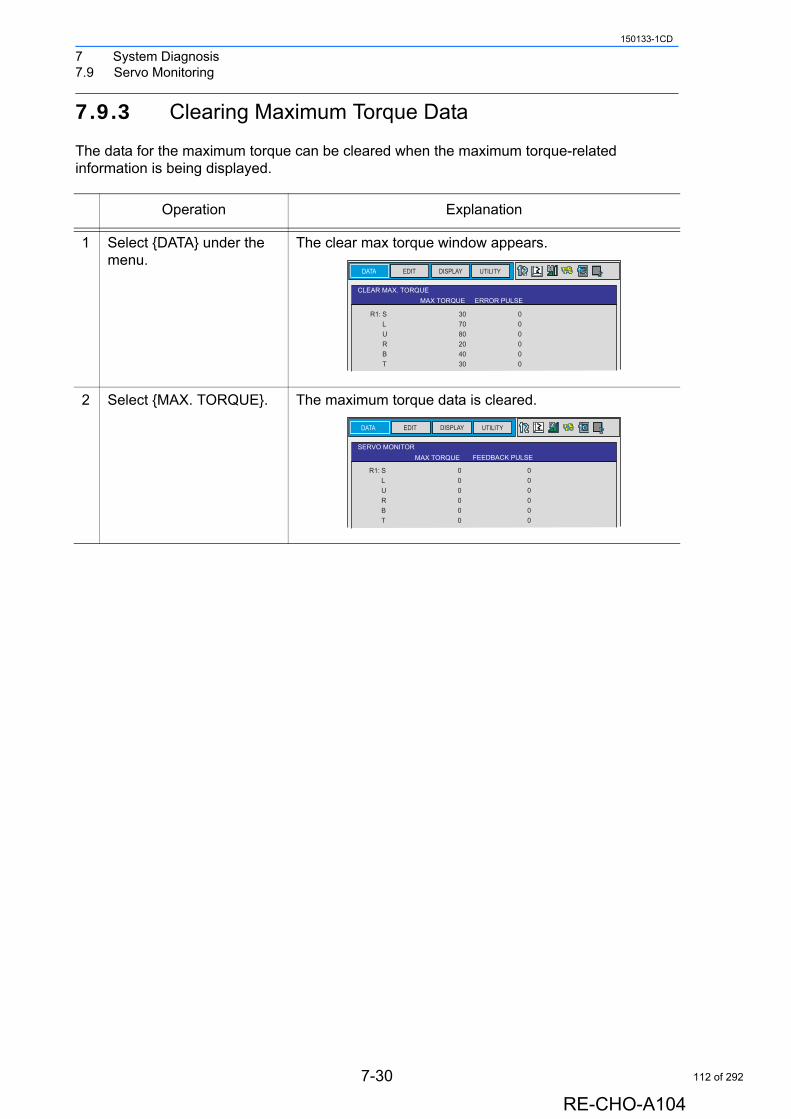
7 System Diagnosis7.9 Servo Monitoring
150133-1CD
7.9.3 Clearing Maximum Torque Data
The data for the maximum torque can be cleared when the maximum torque-related information is being displayed.
Operation Explanation
1 Select {DATA} under the menu.
The clear max torque window appears.
2 Select {MAX. TORQUE}. The maximum torque data is cleared.
DATA EDIT DISPLAY UTILITY
CLEAR MAX. TORQUEMAX TORQUE ERROR PULSE
S��� 30�L��� 70�U��� 80�R��� 20�B��� 40�T��� 30
0� 0� 0� 0� 0� 0
R1:
EDIT DISPLAY UTILITY
SERVO MONITORMAX TORQUE FEEDBACK PULSE
DATA
0� 0� 0� 0� 0� 0
S��� 0�L��� 0�U��� 0�R��� 0�B��� 0�T��� 0
R1:
7-30
RE-CHO-A104
112 of 292
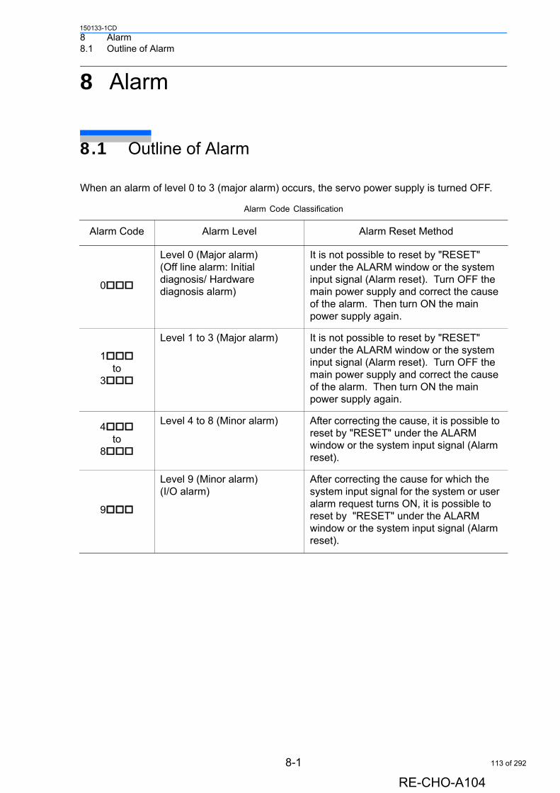
8 Alarm8.1 Outline of Alarm
150133-1CD
8 Alarm
8.1 Outline of Alarm
When an alarm of level 0 to 3 (major alarm) occurs, the servo power supply is turned OFF.
Alarm Code Classification
Alarm Code Alarm Level Alarm Reset Method
0
Level 0 (Major alarm)(Off line alarm: Initial diagnosis/ Hardware diagnosis alarm)
It is not possible to reset by "RESET" under the ALARM window or the system input signal (Alarm reset). Turn OFF the main power supply and correct the cause of the alarm. Then turn ON the main power supply again.
1to
3
Level 1 to 3 (Major alarm) It is not possible to reset by "RESET" under the ALARM window or the system input signal (Alarm reset). Turn OFF the main power supply and correct the cause of the alarm. Then turn ON the main power supply again.
4to
8
Level 4 to 8 (Minor alarm) After correcting the cause, it is possible to reset by "RESET" under the ALARM window or the system input signal (Alarm reset).
9
Level 9 (Minor alarm)(I/O alarm)
After correcting the cause for which the system input signal for the system or user alarm request turns ON, it is possible to reset by "RESET" under the ALARM window or the system input signal (Alarm reset).
8-1
RE-CHO-A104
113 of 292
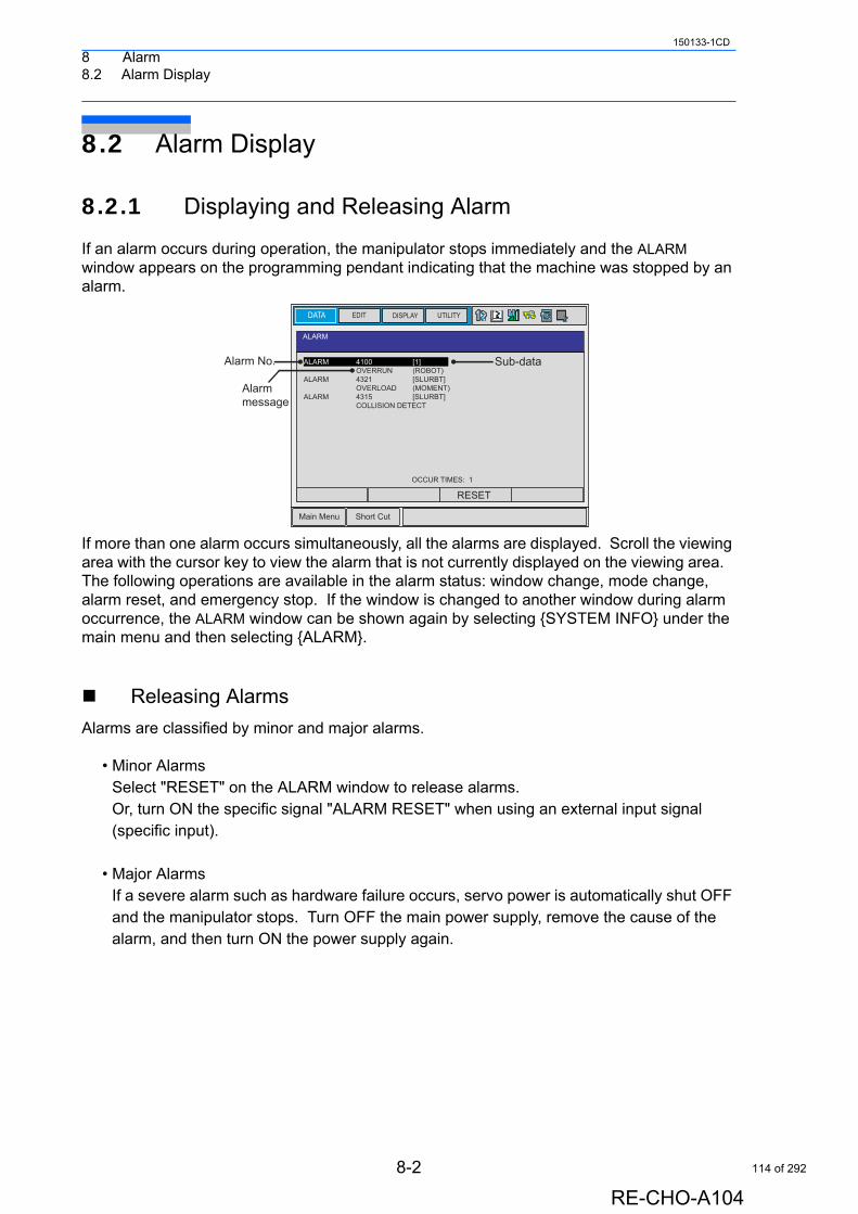
8 Alarm8.2 Alarm Display
150133-1CD
8.2 Alarm Display
8.2.1 Displaying and Releasing Alarm
If an alarm occurs during operation, the manipulator stops immediately and the ALARM window appears on the programming pendant indicating that the machine was stopped by an alarm.
If more than one alarm occurs simultaneously, all the alarms are displayed. Scroll the viewing area with the cursor key to view the alarm that is not currently displayed on the viewing area. The following operations are available in the alarm status: window change, mode change, alarm reset, and emergency stop. If the window is changed to another window during alarm occurrence, the ALARM window can be shown again by selecting {SYSTEM INFO} under the main menu and then selecting {ALARM}.
Releasing Alarms
Alarms are classified by minor and major alarms.
• Minor AlarmsSelect "RESET" on the ALARM window to release alarms.Or, turn ON the specific signal "ALARM RESET" when using an external input signal (specific input).
• Major AlarmsIf a severe alarm such as hardware failure occurs, servo power is automatically shut OFF and the manipulator stops. Turn OFF the main power supply, remove the cause of the alarm, and then turn ON the power supply again.
ALARM
DATA EDIT DISPLAY UTILITY
Main Menu Short Cut
Alarm No.
Alarm message
Sub-dataALARM � 4100�� [1]�� OVERRUN � (ROBOT)ALARM � 4321�� [SLURBT]�� OVERLOAD� (MOMENT)ALARM � 4315�� [SLURBT]�� COLLISION DETECT
OCCUR TIMES: 1
RESET
8-2
RE-CHO-A104
114 of 292
8 Alarm8.2 Alarm Display
150133-1CD
8.2.2 Special Alarm Display
Sub Data
Sub data such as data for the axis where the alarm occurred, may also be displayed for some alarms.• Decimal data
Without signs: 0 to 65535With signs: -32768 to 32767
• Binary dataThe alarm occurrence data becomes “1.”With 8 bits: 0000_0001With 16 bits: 00000001_00000001
• Axis dataThe axis where the alarm occurred is highlighted.
With robot axis: Robots 1 to 4
With base axis: Robots 1 to 4 With station axis: Stations 1 to 12
• XYZ coordinate dataThe coordinates where the alarm occurred are highlighted.
• 123 dataThe data for which the alarm occurred is highlighted.
• Control group dataThe control group where the alarm occurred is highlighted.
Multiple SERVOPACK System
In a system using more than one SERVOPACK, the number of the SERVOPACK where the alarm occurred is also displayed. The S1 switch of the AXA01 circuit board shows the SERVOPACK number.SV#1: SERVOPACK 1 (AXA01 circuit board S1 switch: 0)SV#2: SERVOPACK 2 (AXA01 circuit board S1 switch: 1)SV#3: SERVOPACK 3 (AXA01 circuit board S1 switch: 2)SV#4: SERVOPACK 4 (AXA01 circuit board S1 switch: 3)
[ S L U R B T ]
[ 1 2 3 ]
[ 1 2 3 ]
[ X Y Z ]
[ X Y Z Tx Ty Tz ]
[ 1 2 3 ]
[ R1 R2 S1 S2 S3 ]
8-3
RE-CHO-A104
115 of 292
8 Alarm8.2 Alarm Display
150133-1CD
Independent Control Function (Optional)
In the independent control function (multi-task job), the tasks that were being done when the alarm occurred are also displayed.TASK#0: Master-task jobTASK#1: Sub-task1 job (SUB1)TASK#2: Sub-task2 job (SUB2)TASK#3: Sub-task3 job (SUB3)TASK#4: Sub-task4 job (SUB4)TASK#5: Sub-task5 job (SUB5)TASK#6: Sub-task6 job (SUB6)TASK#7: Sub-task7 job (SUB7)
8-4
RE-CHO-A104
116 of 292
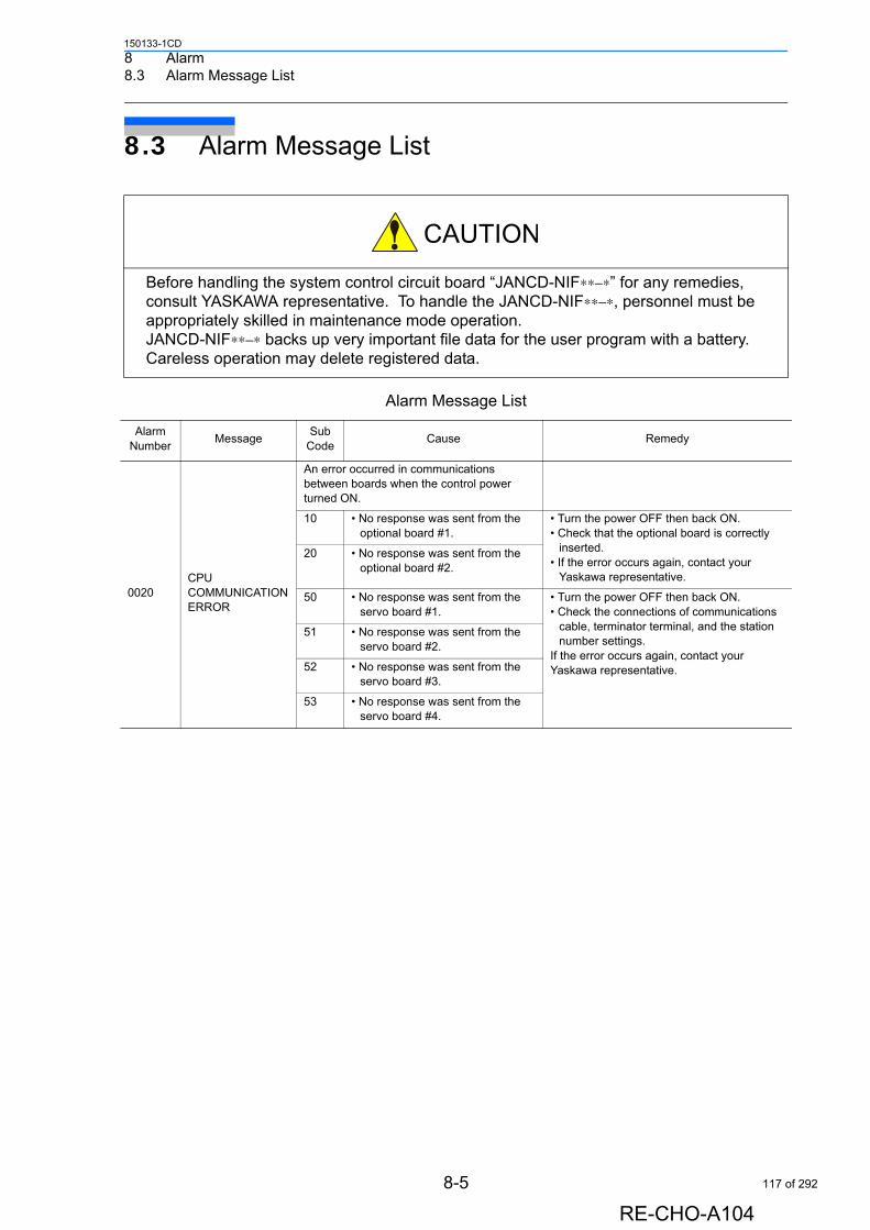
8 Alarm8.3 Alarm Message List
150133-1CD
8.3 Alarm Message List
Before handling the system control circuit board “JANCD-NIF∗∗−∗” for any remedies, consult YASKAWA representative. To handle the JANCD-NIF∗∗−∗, personnel must be appropriately skilled in maintenance mode operation.JANCD-NIF∗∗−∗ backs up very important file data for the user program with a battery. Careless operation may delete registered data.
Alarm Message List
Alarm Number
MessageSub
CodeCause Remedy
0020CPU COMMUNICATION ERROR
An error occurred in communications between boards when the control power turned ON.
10 • No response was sent from the optional board #1.
• Turn the power OFF then back ON. • Check that the optional board is correctly
inserted. • If the error occurs again, contact your
Yaskawa representative.
20 • No response was sent from the optional board #2.
50 • No response was sent from the servo board #1.
• Turn the power OFF then back ON.• Check the connections of communications
cable, terminator terminal, and the station number settings.
If the error occurs again, contact your Yaskawa representative.
51 • No response was sent from the servo board #2.
52 • No response was sent from the servo board #3.
53 • No response was sent from the servo board #4.
8-5
RE-CHO-A104
117 of 292
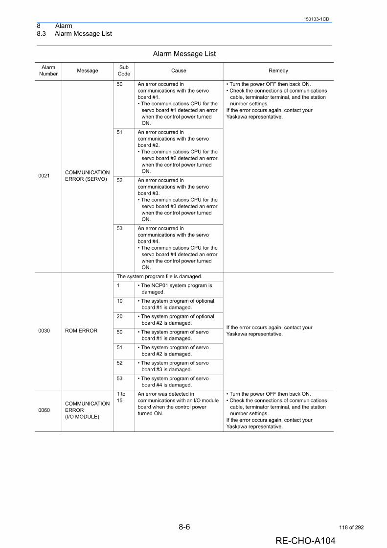
8 Alarm8.3 Alarm Message List
150133-1CD
0021COMMUNICATION ERROR (SERVO)
50 An error occurred in communications with the servo board #1.• The communications CPU for the
servo board #1 detected an error when the control power turned ON.
• Turn the power OFF then back ON. • Check the connections of communications
cable, terminator terminal, and the station number settings.
If the error occurs again, contact your Yaskawa representative.
51 An error occurred in communications with the servo board #2.• The communications CPU for the
servo board #2 detected an error when the control power turned ON.
52 An error occurred in communications with the servo board #3.• The communications CPU for the
servo board #3 detected an error when the control power turned ON.
53 An error occurred in communications with the servo board #4.• The communications CPU for the
servo board #4 detected an error when the control power turned ON.
0030 ROM ERROR
The system program file is damaged.
If the error occurs again, contact your Yaskawa representative.
1 • The NCP01 system program is damaged.
10 • The system program of optional board #1 is damaged.
20 • The system program of optional board #2 is damaged.
50 • The system program of servo board #1 is damaged.
51 • The system program of servo board #2 is damaged.
52 • The system program of servo board #3 is damaged.
53 • The system program of servo board #4 is damaged.
0060COMMUNICATION ERROR (I/O MODULE)
1 to 15
An error was detected in communications with an I/O module board when the control power turned ON.
• Turn the power OFF then back ON.• Check the connections of communications
cable, terminator terminal, and the station number settings.
If the error occurs again, contact your Yaskawa representative.
Alarm Message List
Alarm Number
MessageSub
CodeCause Remedy
8-6
RE-CHO-A104
118 of 292
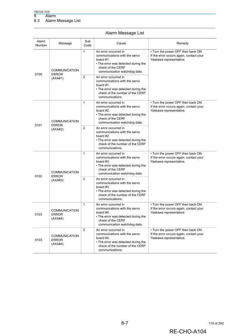
8 Alarm8.3 Alarm Message List
150133-1CD
0100COMMUNICATION ERROR(AXA#1)
1 An error occurred in communications with the servo board #1.• The error was detected during the
check of the CERF communication watchdog data.
• Turn the power OFF then back ON.If the error occurs again, contact your Yaskawa representative.
2 An error occurred in communications with the servo board #1.• The error was detected during the
check of the number of the CERF communications.
0101COMMUNICATION ERROR(AXA#2)
1 An error occurred in communications with the servo board #2.• The error was detected during the
check of the CERF communication watchdog data.
• Turn the power OFF then back ON.If the error occurs again, contact your Yaskawa representative.
2 An error occurred in communications with the servo board #2.• The error was detected during the
check of the number of the CERF communications.
0102COMMUNICATION ERROR(AXA#3)
1 An error occurred in communications with the servo board #3.• The error was detected during the
check of the CERF communication watchdog data.
• Turn the power OFF then back ON.If the error occurs again, contact your Yaskawa representative.
2 An error occurred in communications with the servo board #3.• The error was detected during the
check of the number of the CERF communications.
0103COMMUNICATION ERROR(AXA#4)
1 An error occurred in communications with the servo board #4.• The error was detected during the
check of the CERF communication watchdog data.
• Turn the power OFF then back ON.If the error occurs again, contact your Yaskawa representative.
0103COMMUNICATION ERROR(AXA#4)
2 An error occurred in communications with the servo board #4.• The error was detected during the
check of the number of the CERF communications.
• Turn the power OFF then back ON.If the error occurs again, contact your Yaskawa representative.
Alarm Message List
Alarm Number
MessageSub
CodeCause Remedy
8-7
RE-CHO-A104
119 of 292
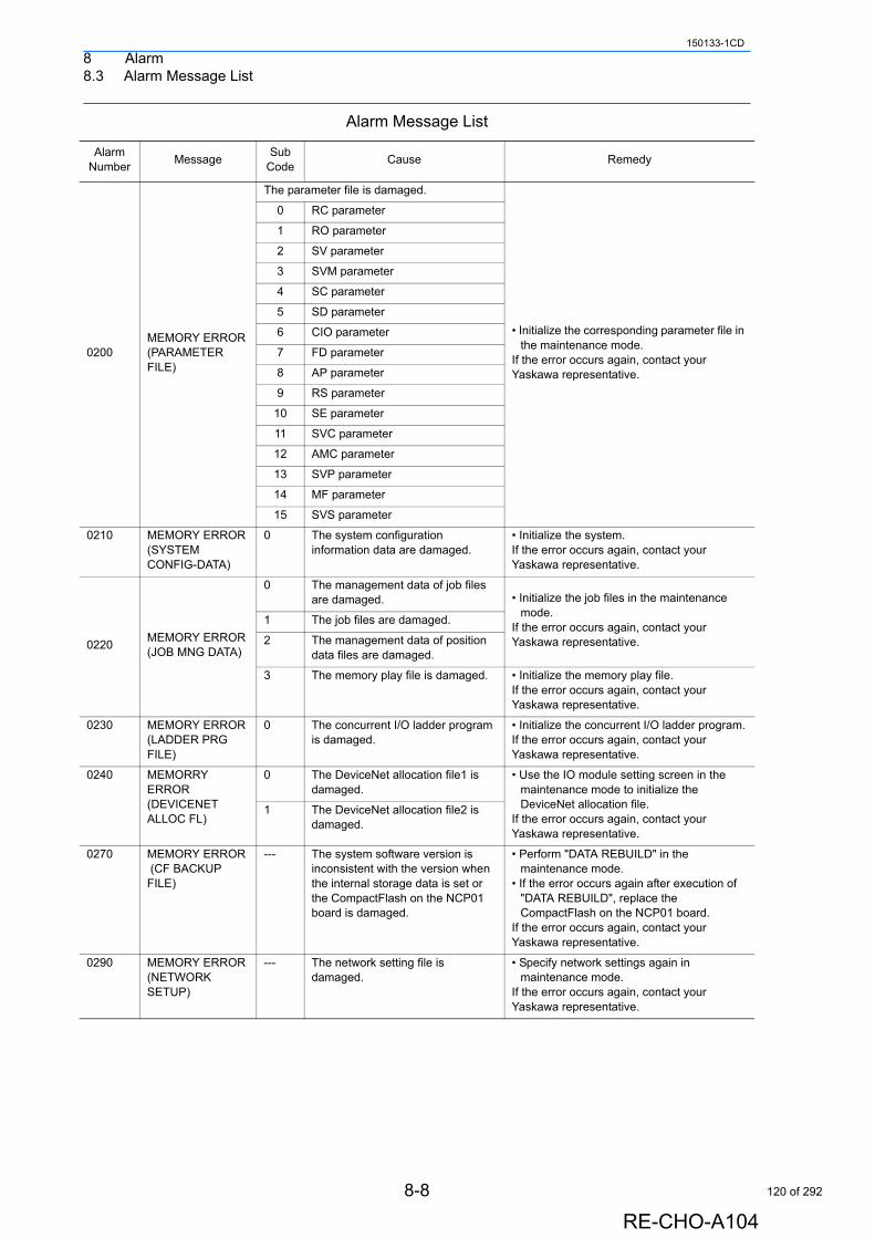
8 Alarm8.3 Alarm Message List
150133-1CD
0200MEMORY ERROR (PARAMETER FILE)
The parameter file is damaged.
• Initialize the corresponding parameter file in the maintenance mode.
If the error occurs again, contact your Yaskawa representative.
0 RC parameter
1 RO parameter
2 SV parameter
3 SVM parameter
4 SC parameter
5 SD parameter
6 CIO parameter
7 FD parameter
8 AP parameter
9 RS parameter
10 SE parameter
11 SVC parameter
12 AMC parameter
13 SVP parameter
14 MF parameter
15 SVS parameter
0210 MEMORY ERROR (SYSTEM CONFIG-DATA)
0 The system configuration information data are damaged.
• Initialize the system.If the error occurs again, contact your Yaskawa representative.
0220MEMORY ERROR (JOB MNG DATA)
0 The management data of job files are damaged. • Initialize the job files in the maintenance
mode.If the error occurs again, contact your Yaskawa representative.
1 The job files are damaged.
2 The management data of position data files are damaged.
3 The memory play file is damaged. • Initialize the memory play file.If the error occurs again, contact your Yaskawa representative.
0230 MEMORY ERROR (LADDER PRG FILE)
0 The concurrent I/O ladder program is damaged.
• Initialize the concurrent I/O ladder program.If the error occurs again, contact your Yaskawa representative.
0240 MEMORRY ERROR(DEVICENET ALLOC FL)
0 The DeviceNet allocation file1 is damaged.
• Use the IO module setting screen in the maintenance mode to initialize the DeviceNet allocation file.
If the error occurs again, contact your Yaskawa representative.
1 The DeviceNet allocation file2 is damaged.
0270 MEMORY ERROR (CF BACKUP FILE)
--- The system software version is inconsistent with the version when the internal storage data is set or the CompactFlash on the NCP01 board is damaged.
• Perform "DATA REBUILD" in the maintenance mode.
• If the error occurs again after execution of "DATA REBUILD", replace the CompactFlash on the NCP01 board.
If the error occurs again, contact your Yaskawa representative.
0290 MEMORY ERROR(NETWORK SETUP)
--- The network setting file is damaged.
• Specify network settings again in maintenance mode.
If the error occurs again, contact your Yaskawa representative.
Alarm Message List
Alarm Number
MessageSub
CodeCause Remedy
8-8
RE-CHO-A104
120 of 292
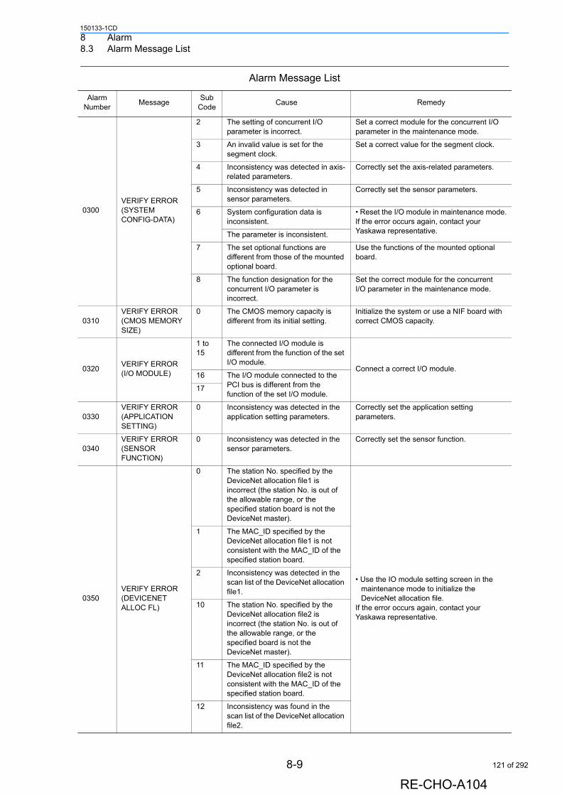
8 Alarm8.3 Alarm Message List
150133-1CD
0300VERIFY ERROR (SYSTEM CONFIG-DATA)
2 The setting of concurrent I/O parameter is incorrect.
Set a correct module for the concurrent I/O parameter in the maintenance mode.
3 An invalid value is set for the segment clock.
Set a correct value for the segment clock.
4 Inconsistency was detected in axis-related parameters.
Correctly set the axis-related parameters.
5 Inconsistency was detected in sensor parameters.
Correctly set the sensor parameters.
6 System configuration data is inconsistent.
• Reset the I/O module in maintenance mode.If the error occurs again, contact your Yaskawa representative.The parameter is inconsistent.
7 The set optional functions are different from those of the mounted optional board.
Use the functions of the mounted optional board.
8 The function designation for the concurrent I/O parameter is incorrect.
Set the correct module for the concurrent I/O parameter in the maintenance mode.
0310VERIFY ERROR (CMOS MEMORY SIZE)
0 The CMOS memory capacity is different from its initial setting.
Initialize the system or use a NIF board with correct CMOS capacity.
0320VERIFY ERROR (I/O MODULE)
1 to 15
The connected I/O module is different from the function of the set I/O module.
Connect a correct I/O module.16 The I/O module connected to the
PCI bus is different from the function of the set I/O module.
17
0330VERIFY ERROR (APPLICATION SETTING)
0 Inconsistency was detected in the application setting parameters.
Correctly set the application setting parameters.
0340VERIFY ERROR (SENSOR FUNCTION)
0 Inconsistency was detected in the sensor parameters.
Correctly set the sensor function.
0350VERIFY ERROR (DEVICENET ALLOC FL)
0 The station No. specified by the DeviceNet allocation file1 is incorrect (the station No. is out of the allowable range, or the specified station board is not the DeviceNet master).
• Use the IO module setting screen in the maintenance mode to initialize the DeviceNet allocation file.
If the error occurs again, contact your Yaskawa representative.
1 The MAC_ID specified by the DeviceNet allocation file1 is not consistent with the MAC_ID of the specified station board.
2 Inconsistency was detected in the scan list of the DeviceNet allocation file1.
10 The station No. specified by the DeviceNet allocation file2 is incorrect (the station No. is out of the allowable range, or the specified board is not the DeviceNet master).
11 The MAC_ID specified by the DeviceNet allocation file2 is not consistent with the MAC_ID of the specified station board.
12 Inconsistency was found in the scan list of the DeviceNet allocation file2.
Alarm Message List
Alarm Number
MessageSub
CodeCause Remedy
8-9
RE-CHO-A104
121 of 292
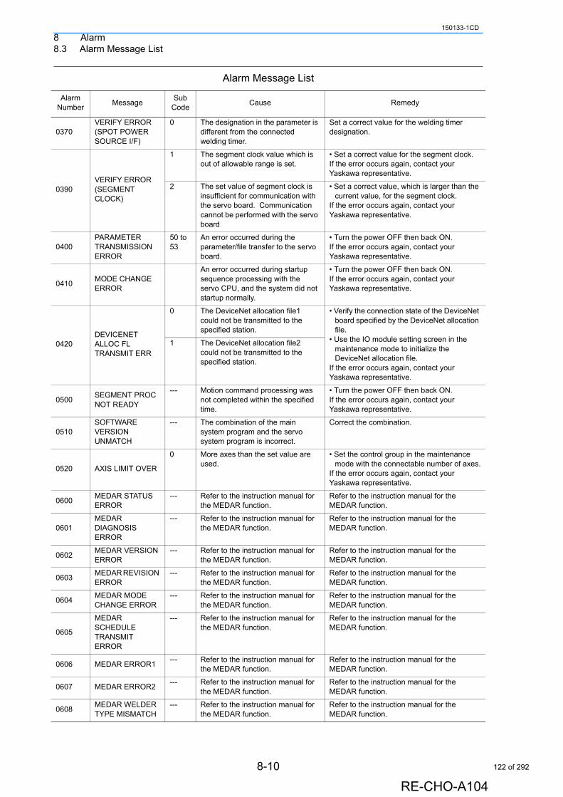
8 Alarm8.3 Alarm Message List
150133-1CD
0370VERIFY ERROR (SPOT POWER SOURCE I/F)
0 The designation in the parameter is different from the connected welding timer.
Set a correct value for the welding timer designation.
0390VERIFY ERROR (SEGMENT CLOCK)
1 The segment clock value which is out of allowable range is set.
• Set a correct value for the segment clock.If the error occurs again, contact your Yaskawa representative.
2 The set value of segment clock is insufficient for communication with the servo board. Communication cannot be performed with the servo board
• Set a correct value, which is larger than the current value, for the segment clock.
If the error occurs again, contact your Yaskawa representative.
0400PARAMETER TRANSMISSION ERROR
50 to 53
An error occurred during the parameter/file transfer to the servo board.
• Turn the power OFF then back ON.If the error occurs again, contact your Yaskawa representative.
0410MODE CHANGE ERROR
An error occurred during startup sequence processing with the servo CPU, and the system did not startup normally.
• Turn the power OFF then back ON.If the error occurs again, contact your Yaskawa representative.
0420DEVICENET ALLOC FL TRANSMIT ERR
0 The DeviceNet allocation file1 could not be transmitted to the specified station.
• Verify the connection state of the DeviceNet board specified by the DeviceNet allocation file.
• Use the IO module setting screen in the maintenance mode to initialize the DeviceNet allocation file.
If the error occurs again, contact your Yaskawa representative.
1 The DeviceNet allocation file2 could not be transmitted to the specified station.
0500SEGMENT PROC NOT READY
--- Motion command processing was not completed within the specified time.
• Turn the power OFF then back ON.If the error occurs again, contact your Yaskawa representative.
0510SOFTWARE VERSION UNMATCH
--- The combination of the main system program and the servo system program is incorrect.
Correct the combination.
0520 AXIS LIMIT OVER
0 More axes than the set value are used.
• Set the control group in the maintenance mode with the connectable number of axes.
If the error occurs again, contact your Yaskawa representative.
0600MEDAR STATUS ERROR
--- Refer to the instruction manual for the MEDAR function.
Refer to the instruction manual for the MEDAR function.
0601MEDAR DIAGNOSIS ERROR
--- Refer to the instruction manual for the MEDAR function.
Refer to the instruction manual for the MEDAR function.
0602MEDAR VERSION ERROR
--- Refer to the instruction manual for the MEDAR function.
Refer to the instruction manual for the MEDAR function.
0603MEDAR REVISION ERROR
--- Refer to the instruction manual for the MEDAR function.
Refer to the instruction manual for the MEDAR function.
0604MEDAR MODE CHANGE ERROR
--- Refer to the instruction manual for the MEDAR function.
Refer to the instruction manual for the MEDAR function.
0605
MEDAR SCHEDULE TRANSMIT ERROR
--- Refer to the instruction manual for the MEDAR function.
Refer to the instruction manual for the MEDAR function.
0606 MEDAR ERROR1--- Refer to the instruction manual for
the MEDAR function.Refer to the instruction manual for the MEDAR function.
0607 MEDAR ERROR2--- Refer to the instruction manual for
the MEDAR function.Refer to the instruction manual for the MEDAR function.
0608MEDAR WELDER TYPE MISMATCH
--- Refer to the instruction manual for the MEDAR function.
Refer to the instruction manual for the MEDAR function.
Alarm Message List
Alarm Number
MessageSub
CodeCause Remedy
8-10
RE-CHO-A104
122 of 292
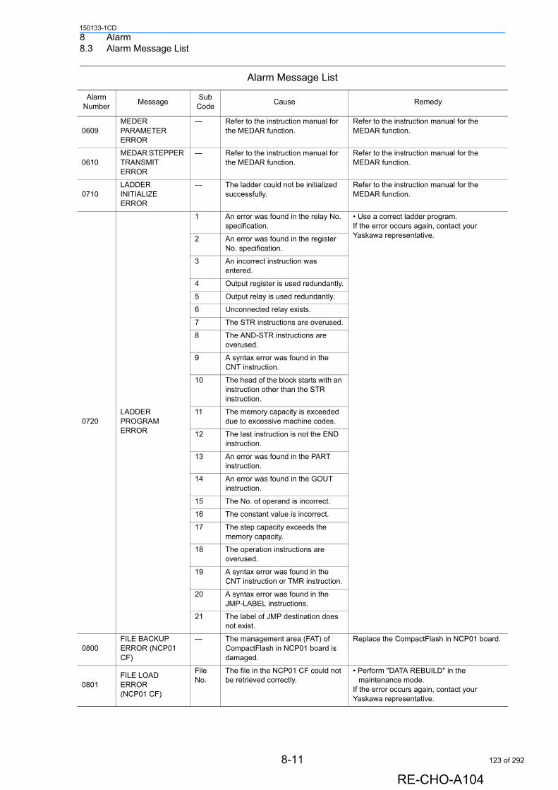
8 Alarm8.3 Alarm Message List
150133-1CD
0609MEDER PARAMETER ERROR
--- Refer to the instruction manual for the MEDAR function.
Refer to the instruction manual for the MEDAR function.
0610MEDAR STEPPER TRANSMIT ERROR
--- Refer to the instruction manual for the MEDAR function.
Refer to the instruction manual for the MEDAR function.
0710LADDER INITIALIZE ERROR
--- The ladder could not be initialized successfully.
Refer to the instruction manual for the MEDAR function.
0720LADDER PROGRAM ERROR
1 An error was found in the relay No. specification.
• Use a correct ladder program.If the error occurs again, contact your Yaskawa representative.2 An error was found in the register
No. specification.
3 An incorrect instruction was entered.
4 Output register is used redundantly.
5 Output relay is used redundantly.
6 Unconnected relay exists.
7 The STR instructions are overused.
8 The AND-STR instructions are overused.
9 A syntax error was found in the CNT instruction.
10 The head of the block starts with an instruction other than the STR instruction.
11 The memory capacity is exceeded due to excessive machine codes.
12 The last instruction is not the END instruction.
13 An error was found in the PART instruction.
14 An error was found in the GOUT instruction.
15 The No. of operand is incorrect.
16 The constant value is incorrect.
17 The step capacity exceeds the memory capacity.
18 The operation instructions are overused.
19 A syntax error was found in the CNT instruction or TMR instruction.
20 A syntax error was found in the JMP-LABEL instructions.
21 The label of JMP destination does not exist.
0800FILE BACKUP ERROR (NCP01 CF)
--- The management area (FAT) of CompactFlash in NCP01 board is damaged.
Replace the CompactFlash in NCP01 board.
0801FILE LOAD ERROR(NCP01 CF)
File No.
The file in the NCP01 CF could not be retrieved correctly.
• Perform "DATA REBUILD" in the maintenance mode.
If the error occurs again, contact your Yaskawa representative.
Alarm Message List
Alarm Number
MessageSub
CodeCause Remedy
8-11
RE-CHO-A104
123 of 292

8 Alarm8.3 Alarm Message List
150133-1CD
0802FILE LOAD ERROR(NCP01 CF)
Error code
An error occurred in access to the NCP01 CF.
• Perform "DATA REBUILD" in the maintenance mode.
If the error occurs again, contact your Yaskawa representative.
0803 FILE ERROR--- An error occurred during the
parameter of Manipulator Model (mecha.rom) loading.
Upgrade to the same version and rewrite the parameter.
Alarm Message List
Alarm Number
MessageSub
CodeCause Remedy
8-12
RE-CHO-A104
124 of 292
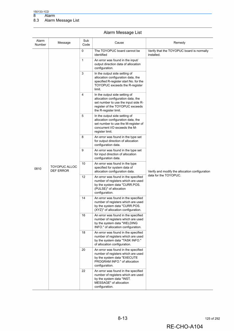
8 Alarm8.3 Alarm Message List
150133-1CD
0810TOYOPUC ALLOC DEF ERROR
0 The TOYOPUC board cannot be identified
Verify that the TOYOPUC board is normally installed.
1 An error was found in the input/output direction data of allocation configuration.
Verify and modify the allocation configuration data for the TOYOPUC.
3 In the output side setting of allocation configuration data, the specified R-register start No. for the TOYOPUC exceeds the R-register limit.
4 In the output side setting of allocation configuration data, the set number to use the input side R-register of the TOYOPUC exceeds the R-register limit.
5 In the output side setting of allocation configuration data, the set number to use the M-register of concurrent I/O exceeds the M-register limit.
8 An error was found in the type set for output direction of allocation configuration data.
9 An error was found in the type set for input direction of allocation configuration data.
10 An error was found in the type specified for system data of allocation configuration data.
12 An error was found in the specified number of registers which are used by the system data "CURR.POS. (PULSE)" of allocation configuration.
14 An error was found in the specified number of registers which are used by the system data "CURR.POS. (XYZ)" of allocation configuration.
16 An error was found in the specified number of registers which are used by the system data "WELDING INFO." of allocation configuration.
18 An error was found in the specified number of registers which are used by the system data "TASK INFO." of allocation configuration.
20 An error was found in the specified number of registers which are used by the system data "EXECUTE PROGRAM INFO." of allocation configuration.
22 An error was found in the specified number of registers which are used by the system data "INST. MESSAGE" of allocation configuration.
Alarm Message List
Alarm Number
MessageSub
CodeCause Remedy
8-13
RE-CHO-A104
125 of 292
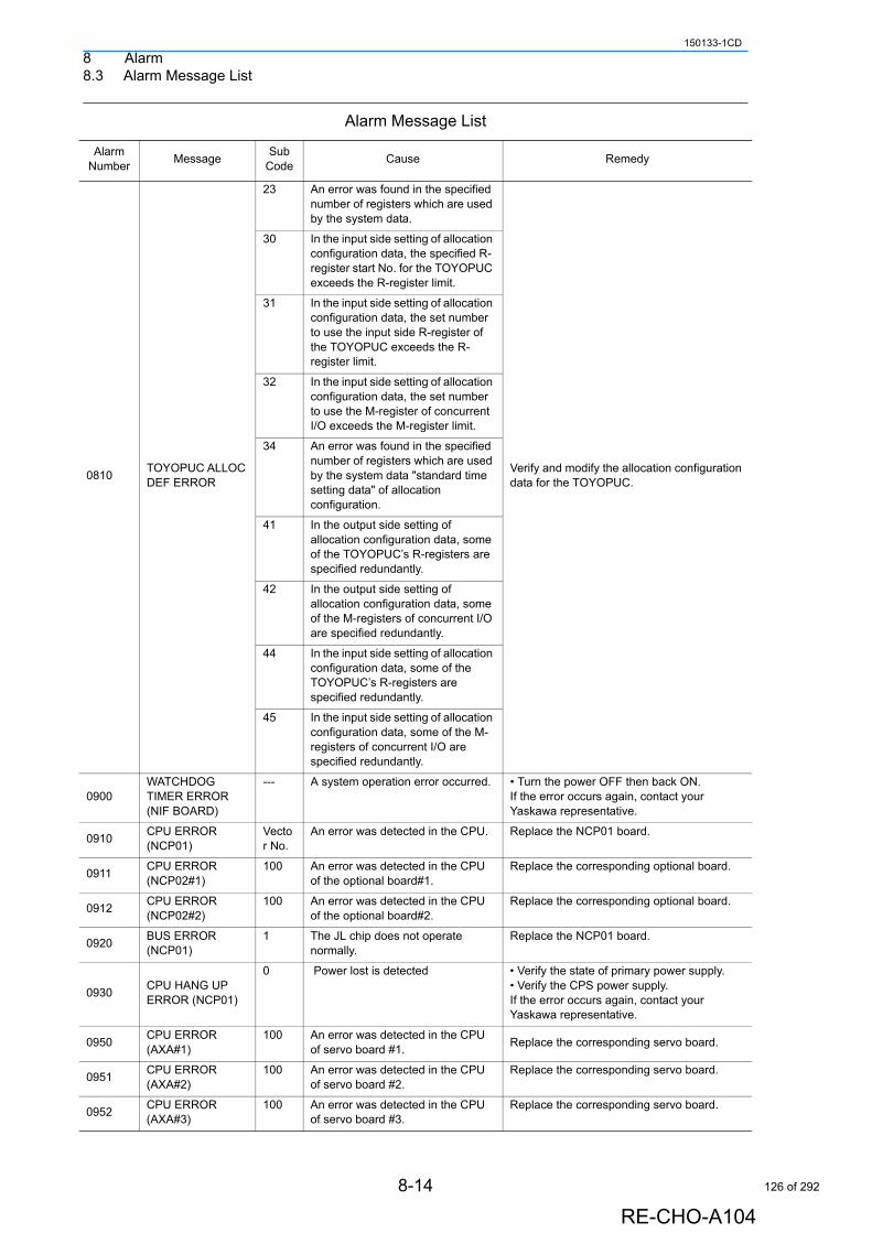
8 Alarm8.3 Alarm Message List
150133-1CD
0810TOYOPUC ALLOC DEF ERROR
23 An error was found in the specified number of registers which are used by the system data.
Verify and modify the allocation configuration data for the TOYOPUC.
30 In the input side setting of allocation configuration data, the specified R-register start No. for the TOYOPUC exceeds the R-register limit.
31 In the input side setting of allocation configuration data, the set number to use the input side R-register of the TOYOPUC exceeds the R-register limit.
32 In the input side setting of allocation configuration data, the set number to use the M-register of concurrent I/O exceeds the M-register limit.
34 An error was found in the specified number of registers which are used by the system data "standard time setting data" of allocation configuration.
41 In the output side setting of allocation configuration data, some of the TOYOPUC’s R-registers are specified redundantly.
42 In the output side setting of allocation configuration data, some of the M-registers of concurrent I/O are specified redundantly.
44 In the input side setting of allocation configuration data, some of the TOYOPUC’s R-registers are specified redundantly.
45 In the input side setting of allocation configuration data, some of the M-registers of concurrent I/O are specified redundantly.
0900WATCHDOG TIMER ERROR (NIF BOARD)
--- A system operation error occurred. • Turn the power OFF then back ON.If the error occurs again, contact your Yaskawa representative.
0910CPU ERROR (NCP01)
Vector No.
An error was detected in the CPU. Replace the NCP01 board.
0911CPU ERROR (NCP02#1)
100 An error was detected in the CPU of the optional board#1.
Replace the corresponding optional board.
0912CPU ERROR (NCP02#2)
100 An error was detected in the CPU of the optional board#2.
Replace the corresponding optional board.
0920BUS ERROR (NCP01)
1 The JL chip does not operate normally.
Replace the NCP01 board.
0930CPU HANG UP ERROR (NCP01)
0 Power lost is detected • Verify the state of primary power supply.• Verify the CPS power supply.If the error occurs again, contact your Yaskawa representative.
0950CPU ERROR(AXA#1)
100 An error was detected in the CPU of servo board #1.
Replace the corresponding servo board.
0951CPU ERROR(AXA#2)
100 An error was detected in the CPU of servo board #2.
Replace the corresponding servo board.
0952CPU ERROR(AXA#3)
100 An error was detected in the CPU of servo board #3.
Replace the corresponding servo board.
Alarm Message List
Alarm Number
MessageSub
CodeCause Remedy
8-14
RE-CHO-A104
126 of 292
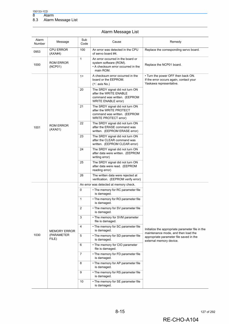
8 Alarm8.3 Alarm Message List
150133-1CD
0953CPU ERROR(AXA#4)
100 An error was detected in the CPU of servo board #4.
Replace the corresponding servo board.
1000ROM ERROR(NCP01)
1 An error occurred in the board or system software (ROM).• A checksum error occurred in the
main ROM.
Replace the NCP01 board.
1001ROM ERROR(AXA01)
1∗ A checksum error occurred in the board or the EEPROM.
(∗: axis No.)
• Turn the power OFF then back ON.If the error occurs again, contact your Yaskawa representative.
20 The SRDY signal did not turn ON after the WRITE ENABLE command was written. (EEPROM WRITE ENABLE error)
21 The SRDY signal did not turn ON after the WRITE PROTECT command was written. (EEPROM WRITE PROTECT error)
22 The SRDY signal did not turn ON after the ERASE command was written. (EEPROM ERASE error)
23 The SRDY signal did not turn ON after the CLEAR command was written. (EEPROM CLEAR error)
24 The SRDY signal did not turn ON after data were written. (EEPROM writing error)
25 The SRDY signal did not turn ON after data were read. (EEPROM reading error)
26 The written data were rejected at verification. (EEPROM verify error)
1030MEMORY ERROR (PARAMETER FILE)
An error was detected at memory check.
Initialize the appropriate parameter file in the maintenance mode, and then load the appropriate parameter file saved in the external memory device.
0 • The memory for RC parameter file is damaged.
1 • The memory for RO parameter file is damaged.
2 • The memory for SV parameter file is damaged.
3 • The memory for SVM parameter file is damaged.
4 • The memory for SC parameter file is damaged.
5 • The memory for SD parameter file is damaged.
6 • The memory for CIO parameter file is damaged.
7 • The memory for FD parameter file is damaged.
8 • The memory for AP parameter file is damaged.
9 • The memory for RS parameter file is damaged.
10 • The memory for SE parameter file is damaged.
Alarm Message List
Alarm Number
MessageSub
CodeCause Remedy
8-15
RE-CHO-A104
127 of 292

8 Alarm8.3 Alarm Message List
150133-1CD
1030MEMORY ERROR (PARAMETER FILE)
11 • The memory for SVC parameter file is damaged.
Initialize the appropriate parameter file in the maintenance mode, and then load the appropriate parameter file saved in the external memory device.
12 • The memory for AMC parameter file is damaged.
13 • The memory for SVP parameter file is damaged.
14 • The memory for MF parameter file is damaged.
15 • The memory for SVS parameter file is damaged.
1031MEMORY ERROR (MOTION1)
The file data used by MOTION are damaged.
Initialize the damaged file in the maintenance mode.
1 • The home position calibration file is damaged.
2 • The tool file is damaged.
3 • The user coordinates file is damaged.
4 • The robot calibration file is damaged.
5 • The tool calibration file is damaged.
6 • The weaving amplitude condition file is damaged.
7 • The home position correction data file is damaged.
8 • The conveyor calibration file is damaged.
9 • The arm and tool interference prevention file is damaged.
20 • The weaving file is damaged.
21 • The Power Source condition data file is damaged.
22 • The welding condition auxiliary file is damaged.
23 • The arc start condition file is damaged.
24 • The arc end condition file is damaged.
25 • The COMARC condition file is damaged.
26 • The COMARC data file is damaged.
27 • The path correction condition file is damaged.
28 • The painting characteristics file is damaged.
29 • The painting condition file is damaged.
30 • The multi-layer index file is damaged.
31 • The multi-layer condition file is damaged.
32 • The sensor monitoring condition file is damaged.
Alarm Message List
Alarm Number
MessageSub
CodeCause Remedy
8-16
RE-CHO-A104
128 of 292
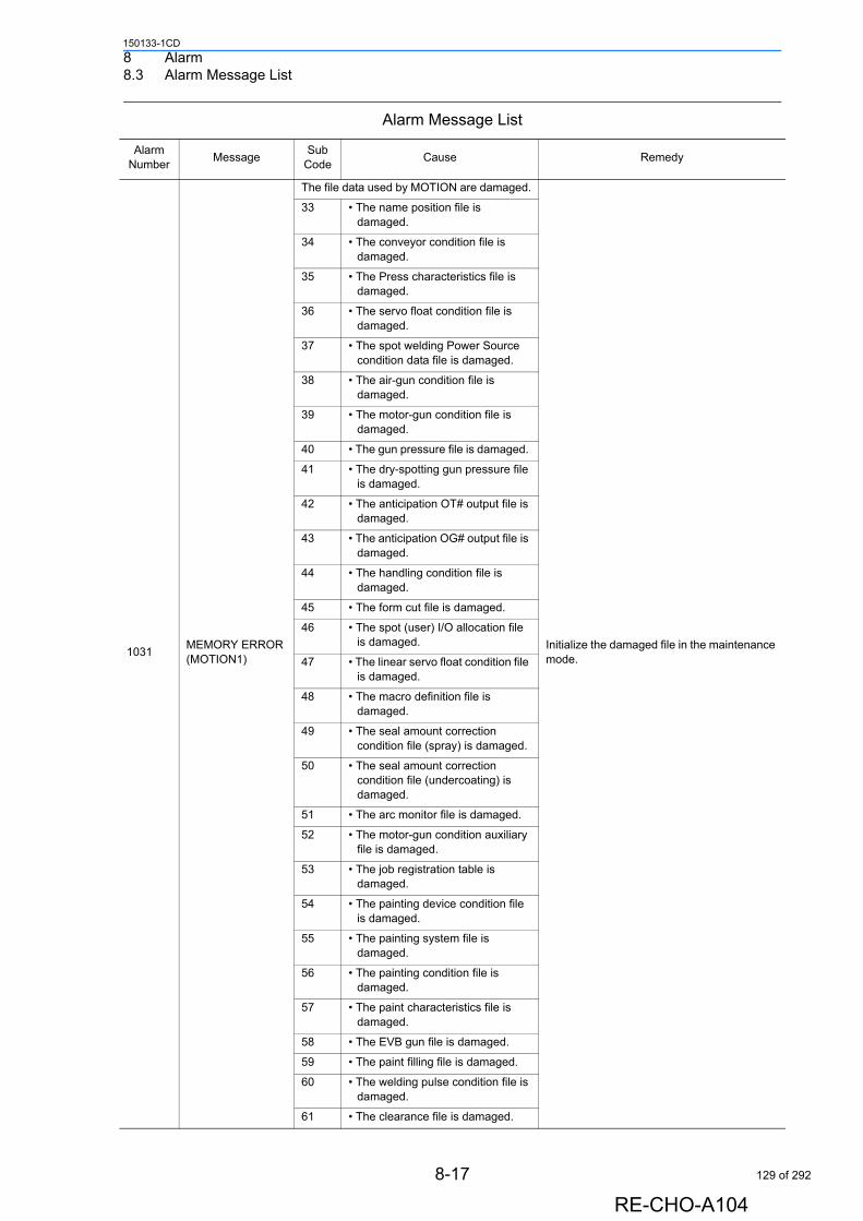
8 Alarm8.3 Alarm Message List
150133-1CD
1031MEMORY ERROR (MOTION1)
The file data used by MOTION are damaged.
Initialize the damaged file in the maintenance mode.
33 • The name position file is damaged.
34 • The conveyor condition file is damaged.
35 • The Press characteristics file is damaged.
36 • The servo float condition file is damaged.
37 • The spot welding Power Source condition data file is damaged.
38 • The air-gun condition file is damaged.
39 • The motor-gun condition file is damaged.
40 • The gun pressure file is damaged.
41 • The dry-spotting gun pressure file is damaged.
42 • The anticipation OT# output file is damaged.
43 • The anticipation OG# output file is damaged.
44 • The handling condition file is damaged.
45 • The form cut file is damaged.
46 • The spot (user) I/O allocation file is damaged.
47 • The linear servo float condition file is damaged.
48 • The macro definition file is damaged.
49 • The seal amount correction condition file (spray) is damaged.
50 • The seal amount correction condition file (undercoating) is damaged.
51 • The arc monitor file is damaged.
52 • The motor-gun condition auxiliary file is damaged.
53 • The job registration table is damaged.
54 • The painting device condition file is damaged.
55 • The painting system file is damaged.
56 • The painting condition file is damaged.
57 • The paint characteristics file is damaged.
58 • The EVB gun file is damaged.
59 • The paint filling file is damaged.
60 • The welding pulse condition file is damaged.
61 • The clearance file is damaged.
Alarm Message List
Alarm Number
MessageSub
CodeCause Remedy
8-17
RE-CHO-A104
129 of 292
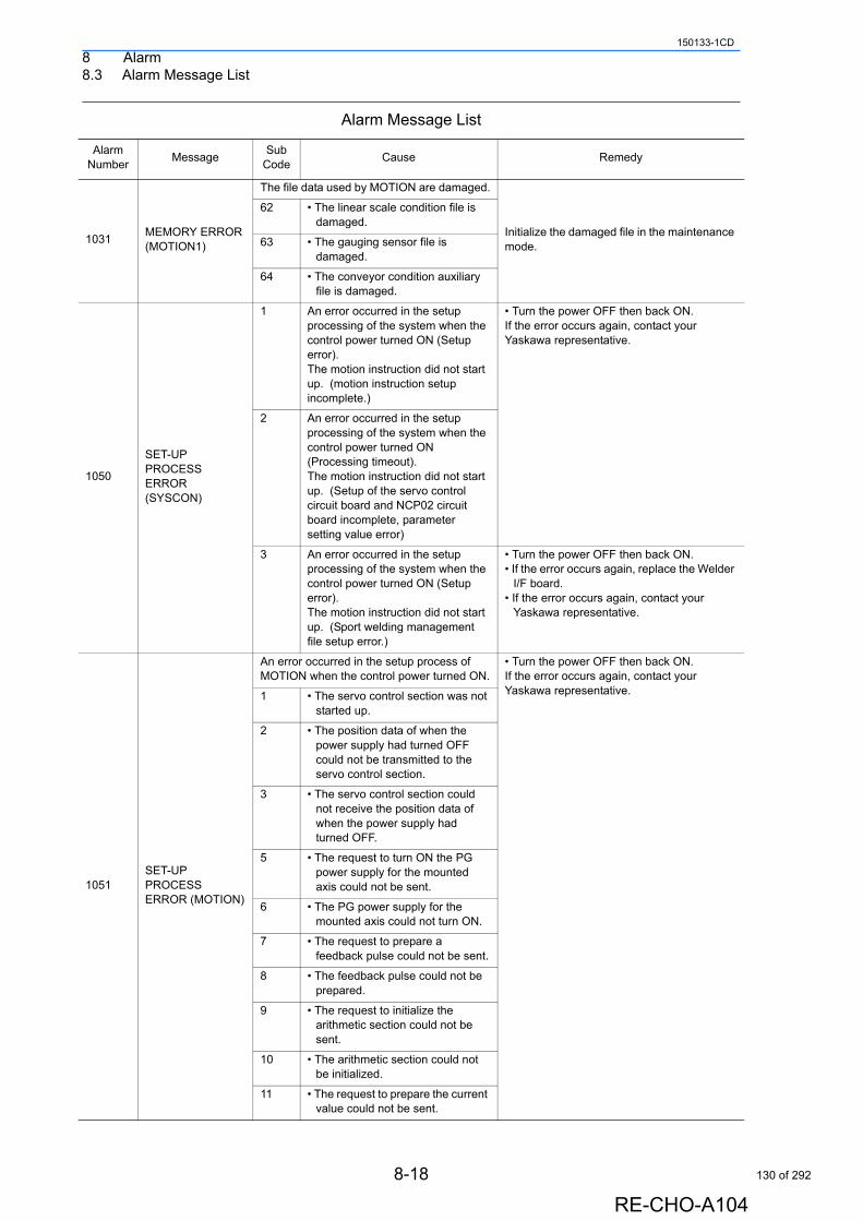
8 Alarm8.3 Alarm Message List
150133-1CD
1031MEMORY ERROR (MOTION1)
The file data used by MOTION are damaged.
Initialize the damaged file in the maintenance mode.
62 • The linear scale condition file is damaged.
63 • The gauging sensor file is damaged.
64 • The conveyor condition auxiliary file is damaged.
1050
SET-UP PROCESS ERROR (SYSCON)
1 An error occurred in the setup processing of the system when the control power turned ON (Setup error).The motion instruction did not start up. (motion instruction setup incomplete.)
• Turn the power OFF then back ON.If the error occurs again, contact your Yaskawa representative.
2 An error occurred in the setup processing of the system when the control power turned ON (Processing timeout).The motion instruction did not start up. (Setup of the servo control circuit board and NCP02 circuit board incomplete, parameter setting value error)
3 An error occurred in the setup processing of the system when the control power turned ON (Setup error).The motion instruction did not start up. (Sport welding management file setup error.)
• Turn the power OFF then back ON. • If the error occurs again, replace the Welder
I/F board.• If the error occurs again, contact your
Yaskawa representative.
1051SET-UP PROCESS ERROR (MOTION)
An error occurred in the setup process of MOTION when the control power turned ON.
• Turn the power OFF then back ON. If the error occurs again, contact your Yaskawa representative.1 • The servo control section was not
started up.
2 • The position data of when the power supply had turned OFF could not be transmitted to the servo control section.
3 • The servo control section could not receive the position data of when the power supply had turned OFF.
5 • The request to turn ON the PG power supply for the mounted axis could not be sent.
6 • The PG power supply for the mounted axis could not turn ON.
7 • The request to prepare a feedback pulse could not be sent.
8 • The feedback pulse could not be prepared.
9 • The request to initialize the arithmetic section could not be sent.
10 • The arithmetic section could not be initialized.
11 • The request to prepare the current value could not be sent.
Alarm Message List
Alarm Number
MessageSub
CodeCause Remedy
8-18
RE-CHO-A104
130 of 292
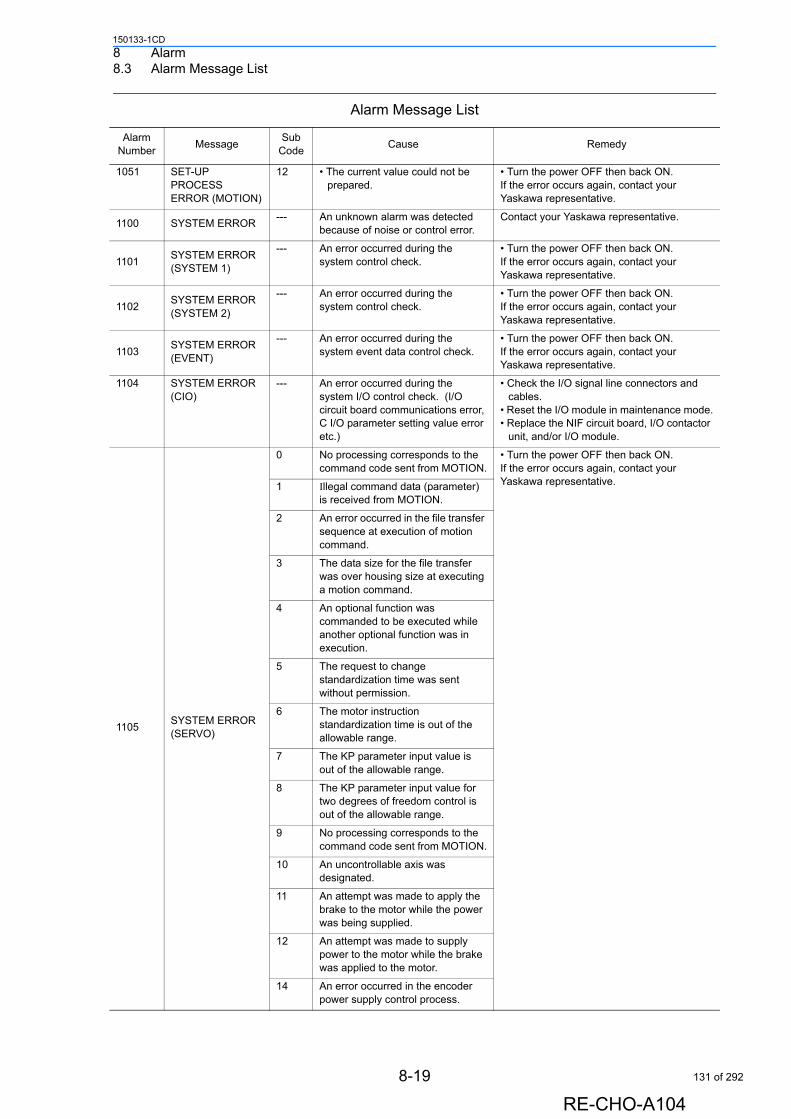
8 Alarm8.3 Alarm Message List
150133-1CD
1051 SET-UP PROCESS ERROR (MOTION)
12 • The current value could not be prepared.
• Turn the power OFF then back ON. If the error occurs again, contact your Yaskawa representative.
1100 SYSTEM ERROR--- An unknown alarm was detected
because of noise or control error.Contact your Yaskawa representative.
1101SYSTEM ERROR (SYSTEM 1)
--- An error occurred during the system control check.
• Turn the power OFF then back ON. If the error occurs again, contact your Yaskawa representative.
1102SYSTEM ERROR (SYSTEM 2)
--- An error occurred during the system control check.
• Turn the power OFF then back ON. If the error occurs again, contact your Yaskawa representative.
1103SYSTEM ERROR (EVENT)
--- An error occurred during the system event data control check.
• Turn the power OFF then back ON. If the error occurs again, contact your Yaskawa representative.
1104 SYSTEM ERROR (CIO)
--- An error occurred during the system I/O control check. (I/O circuit board communications error, C I/O parameter setting value error etc.)
• Check the I/O signal line connectors and cables.
• Reset the I/O module in maintenance mode.• Replace the NIF circuit board, I/O contactor
unit, and/or I/O module.
1105SYSTEM ERROR (SERVO)
0 No processing corresponds to the command code sent from MOTION.
• Turn the power OFF then back ON.If the error occurs again, contact your Yaskawa representative.1 Illegal command data (parameter)
is received from MOTION.
2 An error occurred in the file transfer sequence at execution of motion command.
3 The data size for the file transfer was over housing size at executing a motion command.
4 An optional function was commanded to be executed while another optional function was in execution.
5 The request to change standardization time was sent without permission.
6 The motor instruction standardization time is out of the allowable range.
7 The KP parameter input value is out of the allowable range.
8 The KP parameter input value for two degrees of freedom control is out of the allowable range.
9 No processing corresponds to the command code sent from MOTION.
10 An uncontrollable axis was designated.
11 An attempt was made to apply the brake to the motor while the power was being supplied.
12 An attempt was made to supply power to the motor while the brake was applied to the motor.
14 An error occurred in the encoder power supply control process.
Alarm Message List
Alarm Number
MessageSub
CodeCause Remedy
8-19
RE-CHO-A104
131 of 292
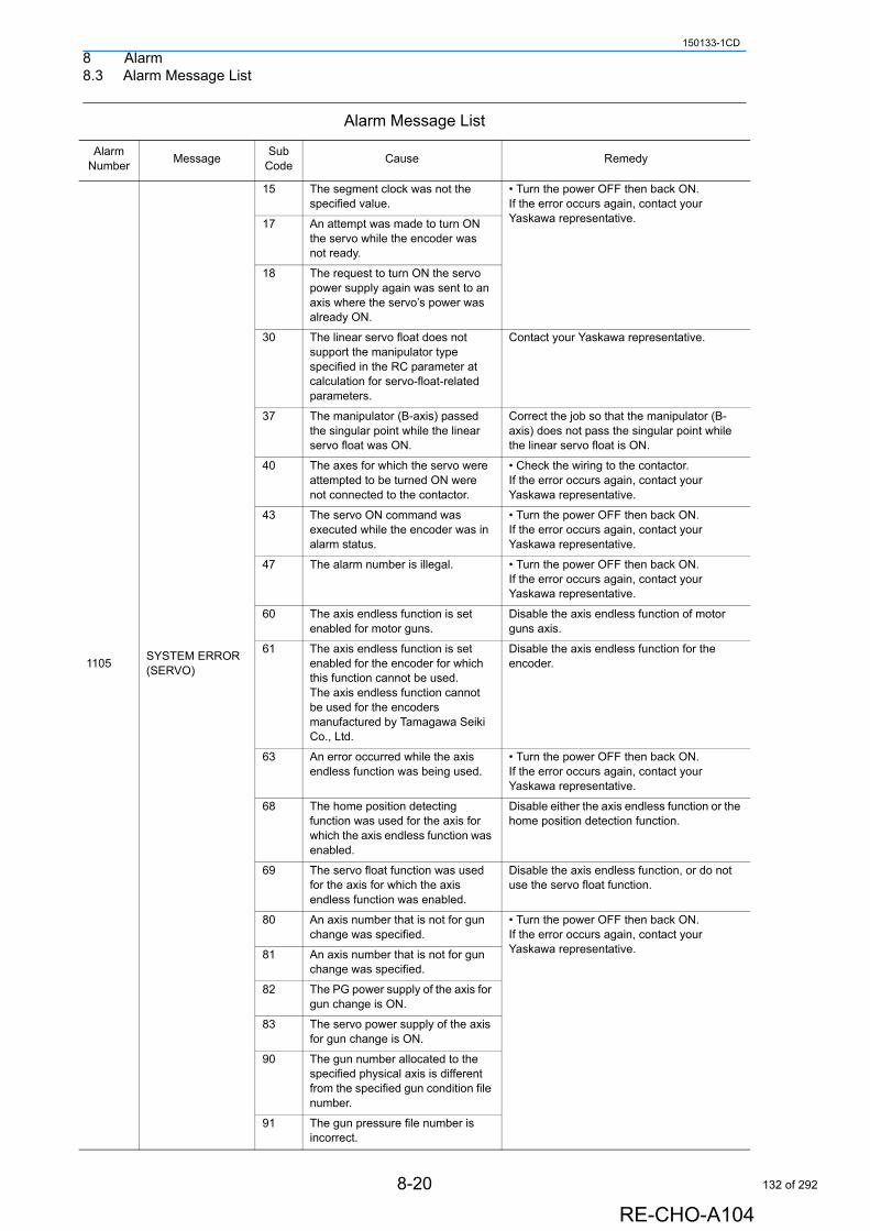
8 Alarm8.3 Alarm Message List
150133-1CD
1105SYSTEM ERROR (SERVO)
15 The segment clock was not the specified value.
• Turn the power OFF then back ON.If the error occurs again, contact your Yaskawa representative.17 An attempt was made to turn ON
the servo while the encoder was not ready.
18 The request to turn ON the servo power supply again was sent to an axis where the servo’s power was already ON.
30 The linear servo float does not support the manipulator type specified in the RC parameter at calculation for servo-float-related parameters.
Contact your Yaskawa representative.
37 The manipulator (B-axis) passed the singular point while the linear servo float was ON.
Correct the job so that the manipulator (B-axis) does not pass the singular point while the linear servo float is ON.
40 The axes for which the servo were attempted to be turned ON were not connected to the contactor.
• Check the wiring to the contactor. If the error occurs again, contact your Yaskawa representative.
43 The servo ON command was executed while the encoder was in alarm status.
• Turn the power OFF then back ON.If the error occurs again, contact your Yaskawa representative.
47 The alarm number is illegal. • Turn the power OFF then back ON.If the error occurs again, contact your Yaskawa representative.
60 The axis endless function is set enabled for motor guns.
Disable the axis endless function of motor guns axis.
61 The axis endless function is set enabled for the encoder for which this function cannot be used.The axis endless function cannot be used for the encoders manufactured by Tamagawa Seiki Co., Ltd.
Disable the axis endless function for the encoder.
63 An error occurred while the axis endless function was being used.
• Turn the power OFF then back ON. If the error occurs again, contact your Yaskawa representative.
68 The home position detecting function was used for the axis for which the axis endless function was enabled.
Disable either the axis endless function or the home position detection function.
69 The servo float function was used for the axis for which the axis endless function was enabled.
Disable the axis endless function, or do not use the servo float function.
80 An axis number that is not for gun change was specified.
• Turn the power OFF then back ON.If the error occurs again, contact your Yaskawa representative.81 An axis number that is not for gun
change was specified.
82 The PG power supply of the axis for gun change is ON.
83 The servo power supply of the axis for gun change is ON.
90 The gun number allocated to the specified physical axis is different from the specified gun condition file number.
91 The gun pressure file number is incorrect.
Alarm Message List
Alarm Number
MessageSub
CodeCause Remedy
8-20
RE-CHO-A104
132 of 292
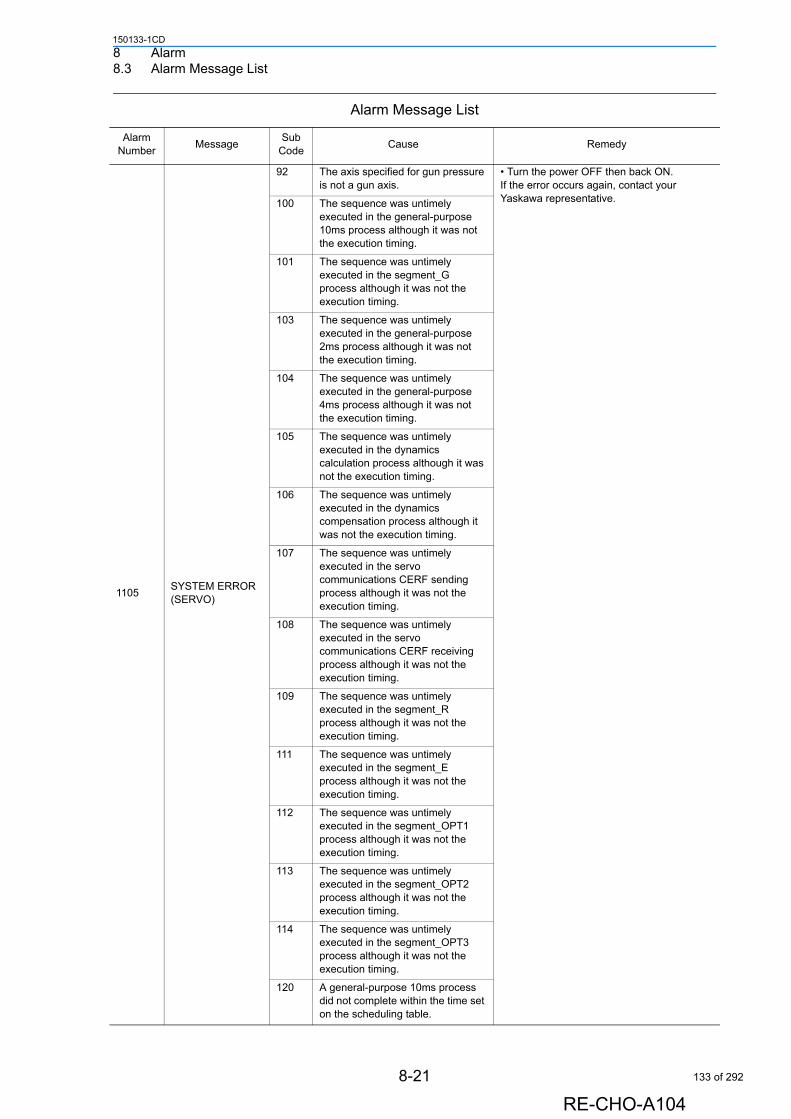
8 Alarm8.3 Alarm Message List
150133-1CD
1105SYSTEM ERROR (SERVO)
92 The axis specified for gun pressure is not a gun axis.
• Turn the power OFF then back ON.If the error occurs again, contact your Yaskawa representative.100 The sequence was untimely
executed in the general-purpose 10ms process although it was not the execution timing.
101 The sequence was untimely executed in the segment_G process although it was not the execution timing.
103 The sequence was untimely executed in the general-purpose 2ms process although it was not the execution timing.
104 The sequence was untimely executed in the general-purpose 4ms process although it was not the execution timing.
105 The sequence was untimely executed in the dynamics calculation process although it was not the execution timing.
106 The sequence was untimely executed in the dynamics compensation process although it was not the execution timing.
107 The sequence was untimely executed in the servo communications CERF sending process although it was not the execution timing.
108 The sequence was untimely executed in the servo communications CERF receiving process although it was not the execution timing.
109 The sequence was untimely executed in the segment_R process although it was not the execution timing.
111 The sequence was untimely executed in the segment_E process although it was not the execution timing.
112 The sequence was untimely executed in the segment_OPT1 process although it was not the execution timing.
113 The sequence was untimely executed in the segment_OPT2 process although it was not the execution timing.
114 The sequence was untimely executed in the segment_OPT3 process although it was not the execution timing.
120 A general-purpose 10ms process did not complete within the time set on the scheduling table.
Alarm Message List
Alarm Number
MessageSub
CodeCause Remedy
8-21
RE-CHO-A104
133 of 292
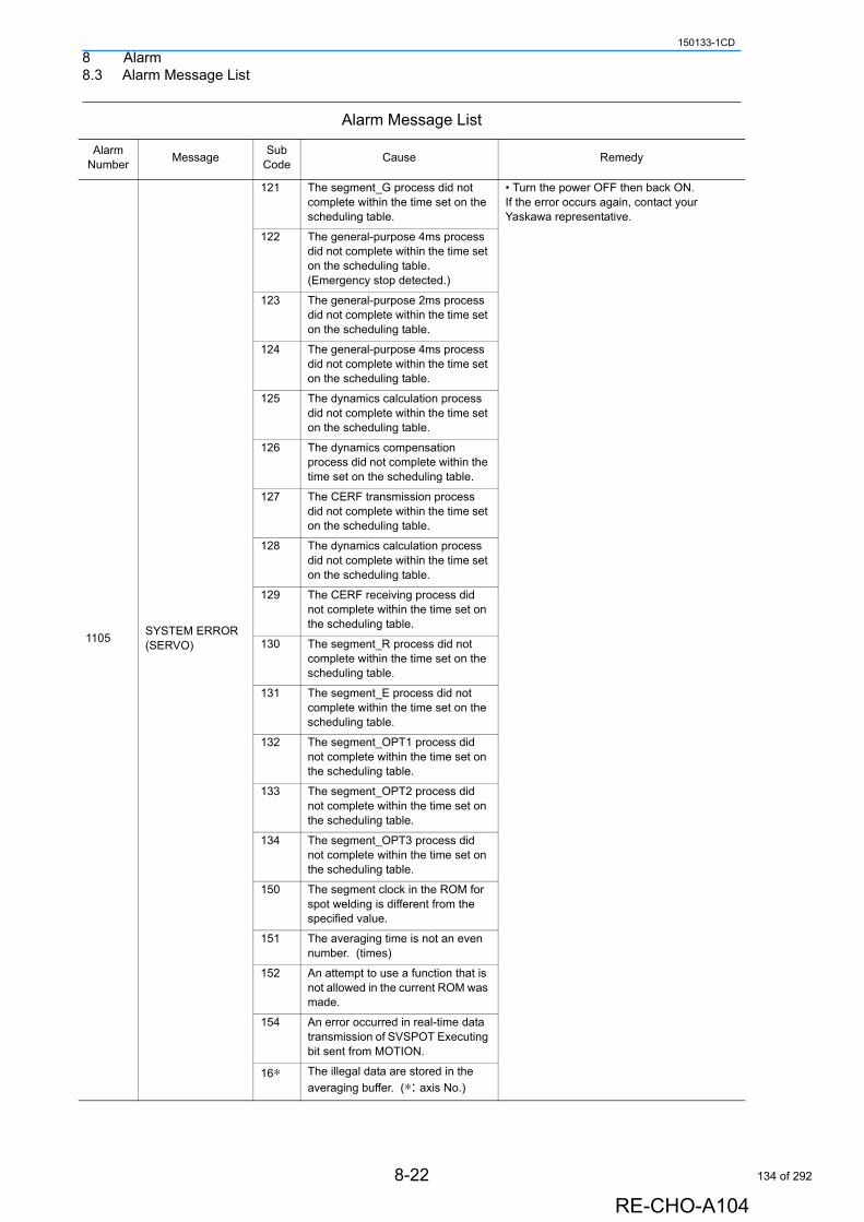
8 Alarm8.3 Alarm Message List
150133-1CD
1105SYSTEM ERROR (SERVO)
121 The segment_G process did not complete within the time set on the scheduling table.
• Turn the power OFF then back ON.If the error occurs again, contact your Yaskawa representative.
122 The general-purpose 4ms process did not complete within the time set on the scheduling table. (Emergency stop detected.)
123 The general-purpose 2ms process did not complete within the time set on the scheduling table.
124 The general-purpose 4ms process did not complete within the time set on the scheduling table.
125 The dynamics calculation process did not complete within the time set on the scheduling table.
126 The dynamics compensation process did not complete within the time set on the scheduling table.
127 The CERF transmission process did not complete within the time set on the scheduling table.
128 The dynamics calculation process did not complete within the time set on the scheduling table.
129 The CERF receiving process did not complete within the time set on the scheduling table.
130 The segment_R process did not complete within the time set on the scheduling table.
131 The segment_E process did not complete within the time set on the scheduling table.
132 The segment_OPT1 process did not complete within the time set on the scheduling table.
133 The segment_OPT2 process did not complete within the time set on the scheduling table.
134 The segment_OPT3 process did not complete within the time set on the scheduling table.
150 The segment clock in the ROM for spot welding is different from the specified value.
151 The averaging time is not an even number. (times)
152 An attempt to use a function that is not allowed in the current ROM was made.
154 An error occurred in real-time data transmission of SVSPOT Executing bit sent from MOTION.
16∗ The illegal data are stored in the
averaging buffer. (∗: axis No.)
Alarm Message List
Alarm Number
MessageSub
CodeCause Remedy
8-22
RE-CHO-A104
134 of 292
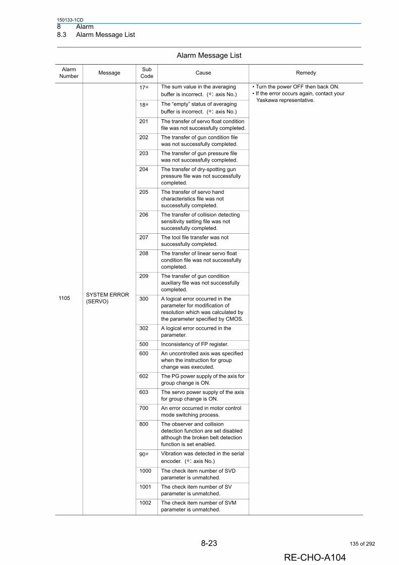
8 Alarm8.3 Alarm Message List
150133-1CD
1105SYSTEM ERROR (SERVO)
17∗ The sum value in the averaging
buffer is incorrect. (∗: axis No.)
• Turn the power OFF then back ON.• If the error occurs again, contact your
Yaskawa representative.18∗ The “empty” status of averaging
buffer is incorrect. (∗: axis No.)
201 The transfer of servo float condition file was not successfully completed.
202 The transfer of gun condition file was not successfully completed.
203 The transfer of gun pressure file was not successfully completed.
204 The transfer of dry-spotting gun pressure file was not successfully completed.
205 The transfer of servo hand characteristics file was not successfully completed.
206 The transfer of collision detecting sensitivity setting file was not successfully completed.
207 The tool file transfer was not successfully completed.
208 The transfer of linear servo float condition file was not successfully completed.
209 The transfer of gun condition auxiliary file was not successfully completed.
300 A logical error occurred in the parameter for modification of resolution which was calculated by the parameter specified by CMOS.
302 A logical error occurred in the parameter.
500 Inconsistency of FP register.
600 An uncontrolled axis was specified when the instruction for group change was executed.
602 The PG power supply of the axis for group change is ON.
603 The servo power supply of the axis for group change is ON.
700 An error occurred in motor control mode switching process.
800 The observer and collision detection function are set disabled although the broken belt detection function is set enabled.
90∗ Vibration was detected in the serial
encoder. (∗: axis No.)
1000 The check item number of SVD parameter is unmatched.
1001 The check item number of SV parameter is unmatched.
1002 The check item number of SVM parameter is unmatched.
Alarm Message List
Alarm Number
MessageSub
CodeCause Remedy
8-23
RE-CHO-A104
135 of 292

8 Alarm8.3 Alarm Message List
150133-1CD
1105SYSTEM ERROR (SERVO)
1003 The check item number of SVP parameter is unmatched.
• Turn the power OFF then back ON.If the error occurs again, contact your Yaskawa representative.1004 The check item number of AMC
parameter is unmatched.
1005 The check item number of MFG parameter is unmatched.
1006 The check item number of MFA parameter is unmatched.
1007 The check item number of SVC parameter is unmatched.
1008 The check item number of SVS parameter is unmatched.
200∗ The status setting to base block is different from that of base block signal reading from JL056. (∗: axis No.)
201∗ The status setting to base block is different from that of base block signal writing to JL056.(∗: axis No.)
202∗ The status setting to base block is different from that of base block signal reading from micro program.(∗: axis No.)
203∗ The mechanical brake remains locked although the base block is released.(∗: axis No.)
204∗ The mechanical brake is not locked although the base block turns ON.(∗: axis No.)
2100 The operating software is not used in the targeted board.
2101 The requested function cannot be performed.
7XXY Internal data error occurred on the servo control circuit boardXX: Internal data No.Y: axis No.
Replace the servo control circuit board.
32807 An error occurred in the first encoder communications.
• Confirm the communication data line and motor specification.
If the error occurs again, contact your Yaskawa representative.
1200 HIGH TEMPERATURE
--- Temperature sensor in the CPS power unit is activated. The internal temperature of the controller is abnormally increased.
• Check for temperature rise in the controller, and check if in-panel cooling fan is rotating.
Cycle the power when the power supply is cooled off.
1204COMMUNICATION ERROR (IO MODULE)
0000_0000_0000_0001
Communications and power supply error occurred in the I/O circuit board. (standard I/O of NIF unit)
• Check the noise source and take countermeasures to reduce the noise.
• Reset the I/O module in maintenance mode.• Replace the NIF circuit board.
****_****_****_***0
Communications and power supply error occurred in the I/O circuit board. (standard I/O of NIF unit)∗: 0 is correct. 1 is incorrect. Bit position of 1 shows the station number of incorrect I/O circuit board.
• Check the I/O signal line (NIF-I/O circuit board) connectors and cables.
• Check the connection of the I/O circuit board and the external device.
• Check the noise source and take countermeasures to reduce the noise.
• Reset the I/O module in maintenance mode.• Replace the NIF circuit board.
Alarm Message List
Alarm Number
MessageSub
CodeCause Remedy
8-24
RE-CHO-A104
136 of 292
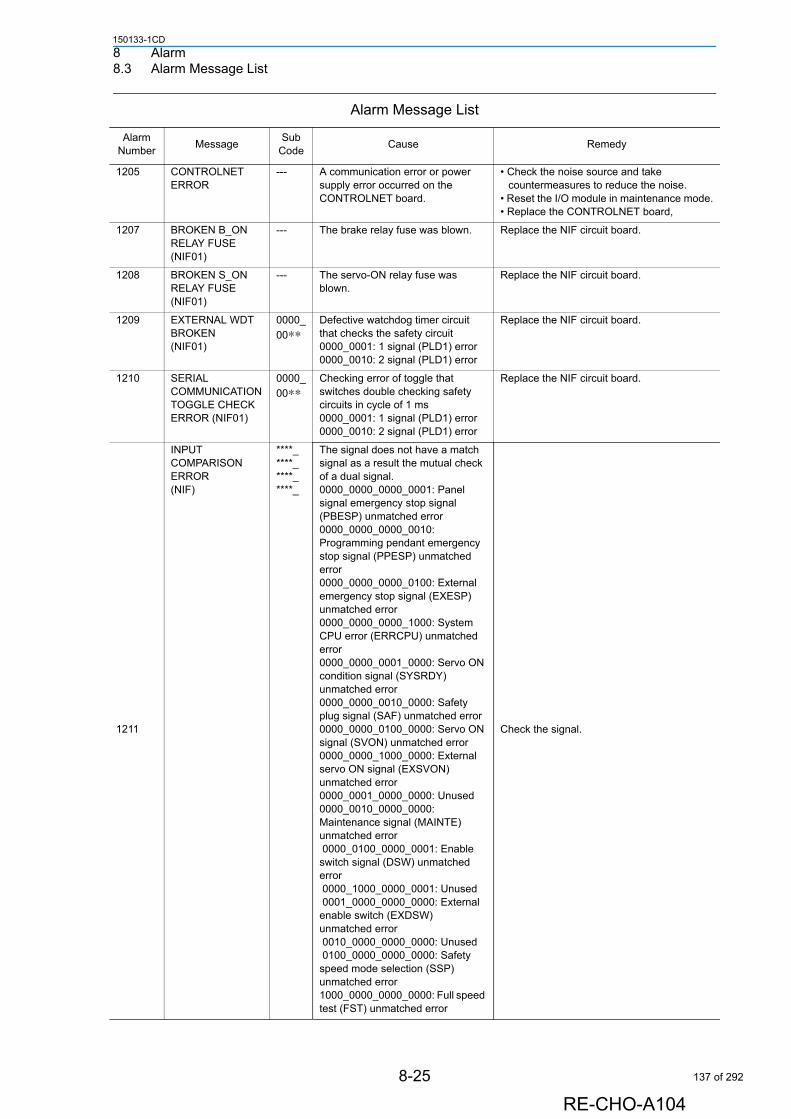
8 Alarm8.3 Alarm Message List
150133-1CD
1205 CONTROLNET ERROR
--- A communication error or power supply error occurred on the CONTROLNET board.
• Check the noise source and take countermeasures to reduce the noise.
• Reset the I/O module in maintenance mode.• Replace the CONTROLNET board,
1207 BROKEN B_ON RELAY FUSE (NIF01)
--- The brake relay fuse was blown. Replace the NIF circuit board.
1208 BROKEN S_ON RELAY FUSE (NIF01)
--- The servo-ON relay fuse was blown.
Replace the NIF circuit board.
1209 EXTERNAL WDT BROKEN (NIF01)
0000_
00∗∗Defective watchdog timer circuit that checks the safety circuit0000_0001: 1 signal (PLD1) error0000_0010: 2 signal (PLD1) error
Replace the NIF circuit board.
1210 SERIAL COMMUNICATION TOGGLE CHECK ERROR (NIF01)
0000_
00∗∗Checking error of toggle that switches double checking safety circuits in cycle of 1 ms0000_0001: 1 signal (PLD1) error0000_0010: 2 signal (PLD1) error
Replace the NIF circuit board.
1211
INPUT COMPARISON ERROR (NIF)
****_****_****_****_
The signal does not have a match signal as a result the mutual check of a dual signal.0000_0000_0000_0001: Panel signal emergency stop signal (PBESP) unmatched error0000_0000_0000_0010: Programming pendant emergency stop signal (PPESP) unmatched error0000_0000_0000_0100: External emergency stop signal (EXESP) unmatched error 0000_0000_0000_1000: System CPU error (ERRCPU) unmatched error 0000_0000_0001_0000: Servo ON condition signal (SYSRDY) unmatched error0000_0000_0010_0000: Safety plug signal (SAF) unmatched error 0000_0000_0100_0000: Servo ON signal (SVON) unmatched error 0000_0000_1000_0000: External servo ON signal (EXSVON) unmatched error 0000_0001_0000_0000: Unused0000_0010_0000_0000: Maintenance signal (MAINTE) unmatched error 0000_0100_0000_0001: Enable switch signal (DSW) unmatched error 0000_1000_0000_0001: Unused 0001_0000_0000_0000: External enable switch (EXDSW) unmatched error 0010_0000_0000_0000: Unused 0100_0000_0000_0000: Safety speed mode selection (SSP) unmatched error1000_0000_0000_0000: Full speed test (FST) unmatched error
Check the signal.
Alarm Message List
Alarm Number
MessageSub
CodeCause Remedy
8-25
RE-CHO-A104
137 of 292

8 Alarm8.3 Alarm Message List
150133-1CD
1212 PLD MUTUAL MONITOR ERROR (NIF01)
0000_
00∗∗The input comparison error occurred.0000_0001: 1 signal (PLD1) error0000_0010: 2 signal (PLD2) error
Check the one of PPESP, PBESP, EXESP, and SAF signals.
1213 MUTUAL WDT ERROR (NIF01)
0000_
00∗∗The input comparison error occurred.0000_0001: 1 signal (PLD1) error0000_0010: 2 signal (PLD2) error
Check the one of PPESP, PBESP, EXESP, and SAF signals.
1214 PBESP RELAY STICKING
0000_
00∗∗The emergency stop button PBESP of the NX100 front door is melted and stuck.0000_0001: 1 signal (PLD1) error0000_0010: 2 signal (PLD2) error
• Confirm that the cable is not short-circuited.• Replace if necessary.
1215 PPESP RELAY STICKING
0000_
00∗∗The emergency stop button of programming pendant PPESP is melted and stuck.0000_0001: 1 signal (PLD1) error0000_0010: 2 signal (PLD2) error
• Confirm that the cable is not short-circuited.• Replace if necessary.
1216 EXESP RELAY STICKING
0000_
00∗∗The external emergency stop button EXESP is melted and stuck.0000_0001: 1 signal (PLD1) error0000_0010: 2 signal (PLD2) error
• Confirm that the cable is not short-circuited.• Replace if necessary.
1217 S_ON RELAY STICKING
0000_
00∗∗The servo-ON relay is melted and stuck.0000_0001: 1 signal (PLD1) error0000_0010: 2 signal (PLD2) error
Replace the servo-ON relay.
1218 B_ON RELAY STICKING
0000_
00∗∗The brake relay is melted and stuck.0000_0001: 1 signal (PLD1) error0000_0010: 2 signal (PLD2) error
Replace the brake relay.
1219 ANOTHER PLD EXT WDT ERROR (NIF BOARD)
0000_
00∗∗The watchdog timer checking the safety circuit is incorrect.
• Turn the power OFF then back ON. If the error occurs again, replace the NIF unit.
1220
LAN COMMUNICATION PARAMETER ERROR
1 Incorrect setting of the IP address which is used in the Ethernet function.
Set the correct IP address.
2 Incorrect setting of the subnet mask which is used in the Ethernet function.
Set the correct subnet mask.
3 Incorrect setting of the default gateway which is used in the Ethernet function.
Set the correct default gateway.
4 Incorrect setting of the host address which is used in the Ethernet function.
Set the correct host address.
30 Incorrect setting of the parameter which is used for the SNTP of the Ethernet function.
Set the network SNTP in maintenance mode.
31 Incorrect setting of the IP address of the SNTP server which is used in the Ethernet function of the SNTP.
Set the correct network SNTP server address in maintenance mode.
32 Incorrect setting of the host name of the SNTP server which is used in the Ethernet function of the SNTP.
Set the correct network SNTP server host name in maintenance mode.
33 Incorrect setting of the parameter of the DFCP which is used in the Ethernet function of the SNTP.
Set the network SNTP in maintenance mode.
Alarm Message List
Alarm Number
MessageSub
CodeCause Remedy
8-26
RE-CHO-A104
138 of 292
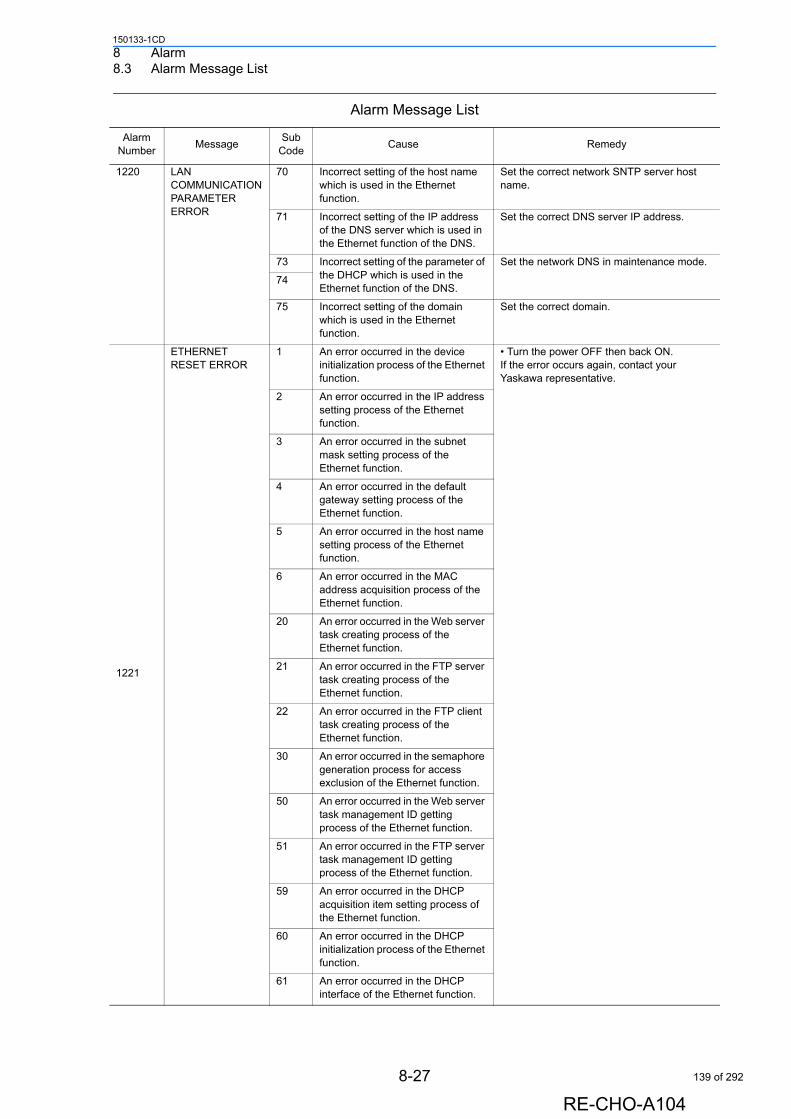
8 Alarm8.3 Alarm Message List
150133-1CD
1220 LAN COMMUNICATION PARAMETER ERROR
70 Incorrect setting of the host name which is used in the Ethernet function.
Set the correct network SNTP server host name.
71 Incorrect setting of the IP address of the DNS server which is used in the Ethernet function of the DNS.
Set the correct DNS server IP address.
73 Incorrect setting of the parameter of the DHCP which is used in the Ethernet function of the DNS.
Set the network DNS in maintenance mode.
74
75 Incorrect setting of the domain which is used in the Ethernet function.
Set the correct domain.
1221
ETHERNET RESET ERROR
1 An error occurred in the device initialization process of the Ethernet function.
• Turn the power OFF then back ON. If the error occurs again, contact your Yaskawa representative.
2 An error occurred in the IP address setting process of the Ethernet function.
3 An error occurred in the subnet mask setting process of the Ethernet function.
4 An error occurred in the default gateway setting process of the Ethernet function.
5 An error occurred in the host name setting process of the Ethernet function.
6 An error occurred in the MAC address acquisition process of the Ethernet function.
20 An error occurred in the Web server task creating process of the Ethernet function.
21 An error occurred in the FTP server task creating process of the Ethernet function.
22 An error occurred in the FTP client task creating process of the Ethernet function.
30 An error occurred in the semaphore generation process for access exclusion of the Ethernet function.
50 An error occurred in the Web server task management ID getting process of the Ethernet function.
51 An error occurred in the FTP server task management ID getting process of the Ethernet function.
59 An error occurred in the DHCP acquisition item setting process of the Ethernet function.
60 An error occurred in the DHCP initialization process of the Ethernet function.
61 An error occurred in the DHCP interface of the Ethernet function.
Alarm Message List
Alarm Number
MessageSub
CodeCause Remedy
8-27
RE-CHO-A104
139 of 292
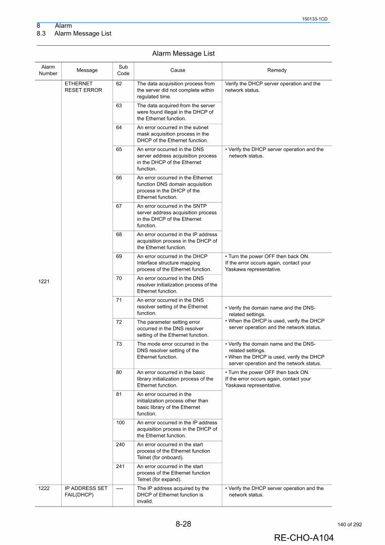
8 Alarm8.3 Alarm Message List
150133-1CD
1221
ETHERNET RESET ERROR
62 The data acquisition process from the server did not complete within regulated time.
Verify the DHCP server operation and the network status.
63 The data acquired from the server were found illegal in the DHCP of the Ethernet function.
64 An error occurred in the subnet mask acquisition process in the DHCP of the Ethernet function.
65 An error occurred in the DNS server address acquisition process in the DHCP of the Ethernet function.
• Verify the DHCP server operation and the network status.
66 An error occurred in the Ethernet function DNS domain acquisition process in the DHCP of the Ethernet function.
67 An error occurred in the SNTP server address acquisition process in the DHCP of the Ethernet function.
68 An error occurred in the IP address acquisition process in the DHCP of the Ethernet function.
69 An error occurred in the DHCP Interface structure mapping process of the Ethernet function.
• Turn the power OFF then back ON.If the error occurs again, contact your Yaskawa representative.
70 An error occurred in the DNS resolver initialization process of the Ethernet function.
71 An error occurred in the DNS resolver setting of the Ethernet function.
• Verify the domain name and the DNS-related settings.
• When the DHCP is used, verify the DHCP server operation and the network status.
72 The parameter setting error occurred in the DNS resolver setting of the Ethernet function.
73 The mode error occurred in the DNS resolver setting of the Ethernet function.
• Verify the domain name and the DNS-related settings.
• When the DHCP is used, verify the DHCP server operation and the network status.
80 An error occurred in the basic library initialization process of the Ethernet function.
• Turn the power OFF then back ON.If the error occurs again, contact your Yaskawa representative.
81 An error occurred in the initialization process other than basic library of the Ethernet function.
100 An error occurred in the IP address acquisition process in the DHCP of the Ethernet function.
240 An error occurred in the start process of the Ethernet function Telnet (for onboard).
241 An error occurred in the start process of the Ethernet function Telnet (for expand).
1222 IP ADDRESS SET FAIL(DHCP)
---- The IP address acquired by the DHCP of Ethernet function is invalid.
• Verify the DHCP server operation and the network status.
Alarm Message List
Alarm Number
MessageSub
CodeCause Remedy
8-28
RE-CHO-A104
140 of 292
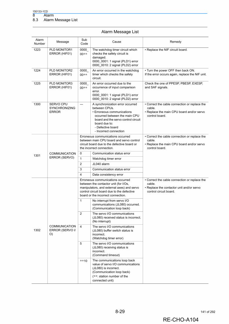
8 Alarm8.3 Alarm Message List
150133-1CD
1223 PLD MONITOR1 ERROR (HIF01)
0000_
00∗∗The watchdog timer circuit which checks the safety circuit is damaged.0000_0001: 1 signal (PLD1) error0000_0010: 2 signal (PLD2) error
• Replace the NIF circuit board.
1224 PLD MONITOR2 ERROR (HIF01)
0000_
00∗∗An error occurred in the watchdog timer which checks the safety circuit.
• Turn the power OFF then back ON. If the error occurs again, replace the NIF unit.
1225 PLD MONITOR3 ERROR (HIF01)
0000_
00∗∗An error occurred due to the occurrence of input comparison error.0000_0001: 1 signal (PLD1) error0000_0010: 2 signal (PLD2) error
Check the one of PPESP, PBESP, EXESP, and SAF signals.
1300 SERVO CPU SYNCHRONIZING ERROR
--- A synchronization error occurred between CPUs.• Erroneous communications
occurred between the main CPU board and the servo control circuit board due to:- Defective board- Incorrect connection
• Correct the cable connection or replace the cable.
• Replace the main CPU board and/or servo control board.
1301COMMUNICATION ERROR (SERVO)
Erroneous communications occurred between main CPU board and servo control circuit board due to the defective board or the incorrect connection.
• Correct the cable connection or replace the cable.
• Replace the main CPU board and/or servo control board.
0 Communication status error
1 Watchdog timer error
2 JL040 alarm
3 Communication status error
4 Data consistency error
1302COMMUNICATION ERROR (SERVO I/O)
Erroneous communications occurred between the contactor unit (for I/Os, manipulators, and external axes) and servo control circuit board due to the defective board or the incorrect connection.
• Correct the cable connection or replace the cable.
• Replace the contactor unit and/or servo control circuit board.
1 No interrupt from servo I/O communications (JL080) occurred.(Communication loop back)
2 The servo I/O communications (JL080) received status is incorrect.(No interrupt)
4 The servo I/O communications (JL080) buffer switch status is incorrect.(Watchdog timer error)
5 The servo I/O communications (JL080) receiving status is incorrect.(Command timeout)
∗∗10 The communications loop back value of servo I/O communications (JL080) is incorrect.(Communication loop back)
(∗∗: station number of the connected unit)
Alarm Message List
Alarm Number
MessageSub
CodeCause Remedy
8-29
RE-CHO-A104
141 of 292
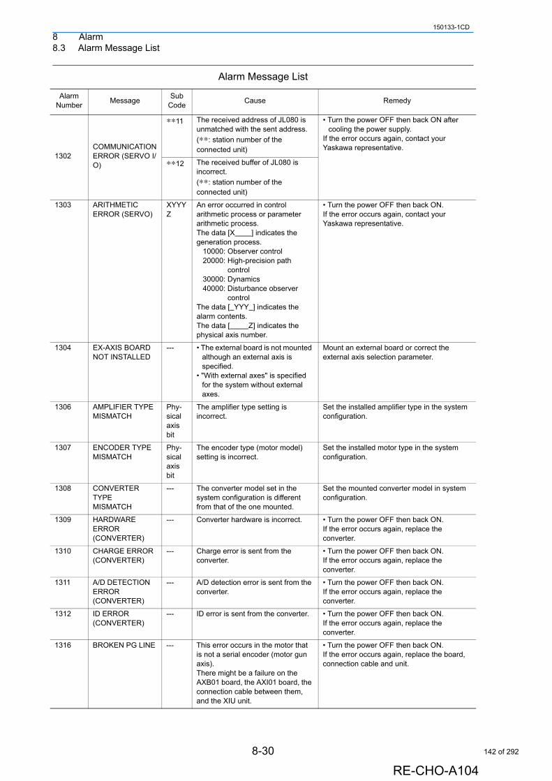
8 Alarm8.3 Alarm Message List
150133-1CD
1302COMMUNICATION ERROR (SERVO I/O)
∗∗11 The received address of JL080 is unmatched with the sent address.
(∗∗: station number of the connected unit)
• Turn the power OFF then back ON after cooling the power supply.
If the error occurs again, contact your Yaskawa representative.
∗∗12 The received buffer of JL080 is incorrect.
(∗∗: station number of the connected unit)
1303 ARITHMETIC ERROR (SERVO)
XYYYZ
An error occurred in control arithmetic process or parameter arithmetic process.The data [X ] indicates the generation process. 10000: Observer control 20000: High-precision path control 30000: Dynamics 40000: Disturbance observer controlThe data [ YYY ] indicates the alarm contents.The data [ Z] indicates the physical axis number.
• Turn the power OFF then back ON.If the error occurs again, contact your Yaskawa representative.
1304 EX-AXIS BOARD NOT INSTALLED
--- • The external board is not mounted although an external axis is specified.
• "With external axes" is specified for the system without external axes.
Mount an external board or correct the external axis selection parameter.
1306 AMPLIFIER TYPE MISMATCH
Phy-sical axis bit
The amplifier type setting is incorrect.
Set the installed amplifier type in the system configuration.
1307 ENCODER TYPE MISMATCH
Phy-sical axis bit
The encoder type (motor model) setting is incorrect.
Set the installed motor type in the system configuration.
1308 CONVERTER TYPE MISMATCH
--- The converter model set in the system configuration is different from that of the one mounted.
Set the mounted converter model in system configuration.
1309 HARDWARE ERROR (CONVERTER)
--- Converter hardware is incorrect. • Turn the power OFF then back ON. If the error occurs again, replace the converter.
1310 CHARGE ERROR (CONVERTER)
--- Charge error is sent from the converter.
• Turn the power OFF then back ON. If the error occurs again, replace the converter.
1311 A/D DETECTION ERROR (CONVERTER)
--- A/D detection error is sent from the converter.
• Turn the power OFF then back ON. If the error occurs again, replace the converter.
1312 ID ERROR (CONVERTER)
--- ID error is sent from the converter. • Turn the power OFF then back ON. If the error occurs again, replace the converter.
1316 BROKEN PG LINE --- This error occurs in the motor that is not a serial encoder (motor gun axis).There might be a failure on the AXB01 board, the AXI01 board, the connection cable between them, and the XIU unit.
• Turn the power OFF then back ON. If the error occurs again, replace the board, connection cable and unit.
Alarm Message List
Alarm Number
MessageSub
CodeCause Remedy
8-30
RE-CHO-A104
142 of 292
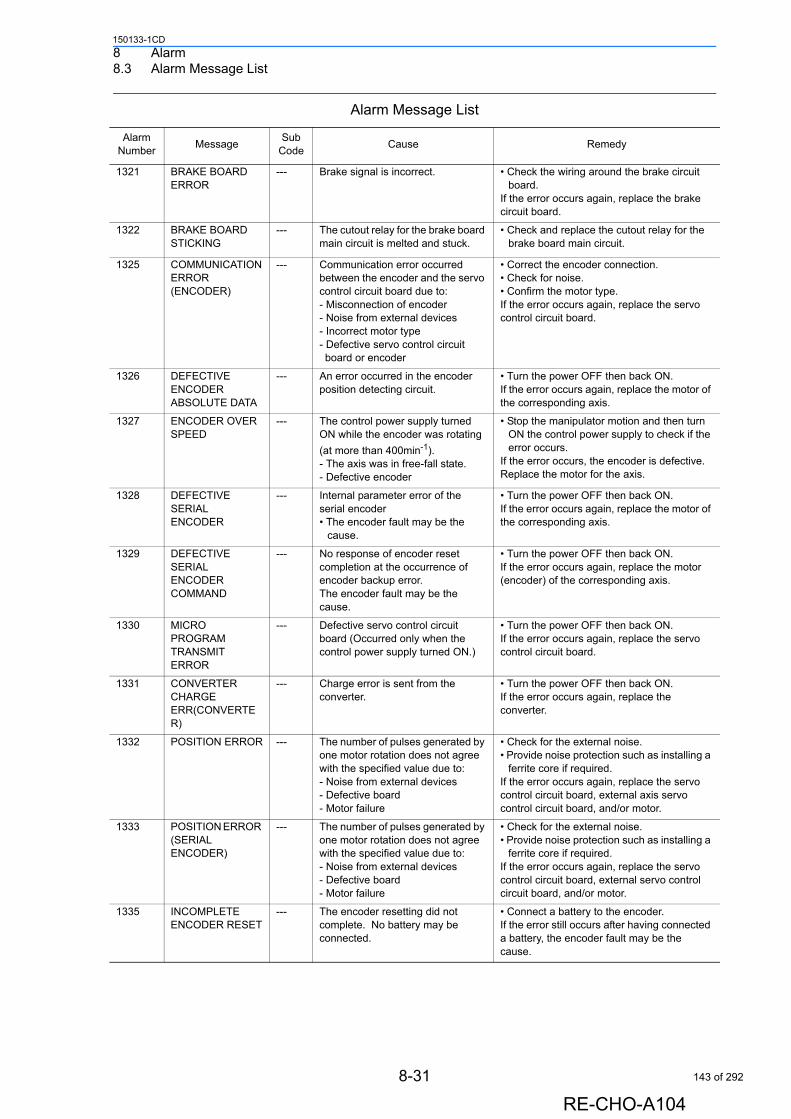
8 Alarm8.3 Alarm Message List
150133-1CD
1321 BRAKE BOARD ERROR
--- Brake signal is incorrect. • Check the wiring around the brake circuit board.
If the error occurs again, replace the brake circuit board.
1322 BRAKE BOARD STICKING
--- The cutout relay for the brake board main circuit is melted and stuck.
• Check and replace the cutout relay for the brake board main circuit.
1325 COMMUNICATION ERROR (ENCODER)
--- Communication error occurred between the encoder and the servo control circuit board due to:- Misconnection of encoder- Noise from external devices- Incorrect motor type - Defective servo control circuit board or encoder
• Correct the encoder connection. • Check for noise. • Confirm the motor type. If the error occurs again, replace the servo control circuit board.
1326 DEFECTIVE ENCODER ABSOLUTE DATA
--- An error occurred in the encoder position detecting circuit.
• Turn the power OFF then back ON. If the error occurs again, replace the motor of the corresponding axis.
1327 ENCODER OVER SPEED
--- The control power supply turned ON while the encoder was rotating
(at more than 400min-1).- The axis was in free-fall state.- Defective encoder
• Stop the manipulator motion and then turn ON the control power supply to check if the error occurs.
If the error occurs, the encoder is defective. Replace the motor for the axis.
1328 DEFECTIVE SERIAL ENCODER
--- Internal parameter error of the serial encoder• The encoder fault may be the
cause.
• Turn the power OFF then back ON. If the error occurs again, replace the motor of the corresponding axis.
1329 DEFECTIVE SERIAL ENCODER COMMAND
--- No response of encoder reset completion at the occurrence of encoder backup error. The encoder fault may be the cause.
• Turn the power OFF then back ON. If the error occurs again, replace the motor (encoder) of the corresponding axis.
1330 MICRO PROGRAM TRANSMIT ERROR
--- Defective servo control circuit board (Occurred only when the control power supply turned ON.)
• Turn the power OFF then back ON. If the error occurs again, replace the servo control circuit board.
1331 CONVERTER CHARGE ERR(CONVERTER)
--- Charge error is sent from the converter.
• Turn the power OFF then back ON.If the error occurs again, replace the converter.
1332 POSITION ERROR --- The number of pulses generated by one motor rotation does not agree with the specified value due to:- Noise from external devices - Defective board- Motor failure
• Check for the external noise.• Provide noise protection such as installing a
ferrite core if required.If the error occurs again, replace the servo control circuit board, external axis servo control circuit board, and/or motor.
1333 POSITION ERROR (SERIAL ENCODER)
--- The number of pulses generated by one motor rotation does not agree with the specified value due to:- Noise from external devices - Defective board- Motor failure
• Check for the external noise.• Provide noise protection such as installing a
ferrite core if required.If the error occurs again, replace the servo control circuit board, external servo control circuit board, and/or motor.
1335 INCOMPLETE ENCODER RESET
--- The encoder resetting did not complete. No battery may be connected.
• Connect a battery to the encoder. If the error still occurs after having connected a battery, the encoder fault may be the cause.
Alarm Message List
Alarm Number
MessageSub
CodeCause Remedy
8-31
RE-CHO-A104
143 of 292
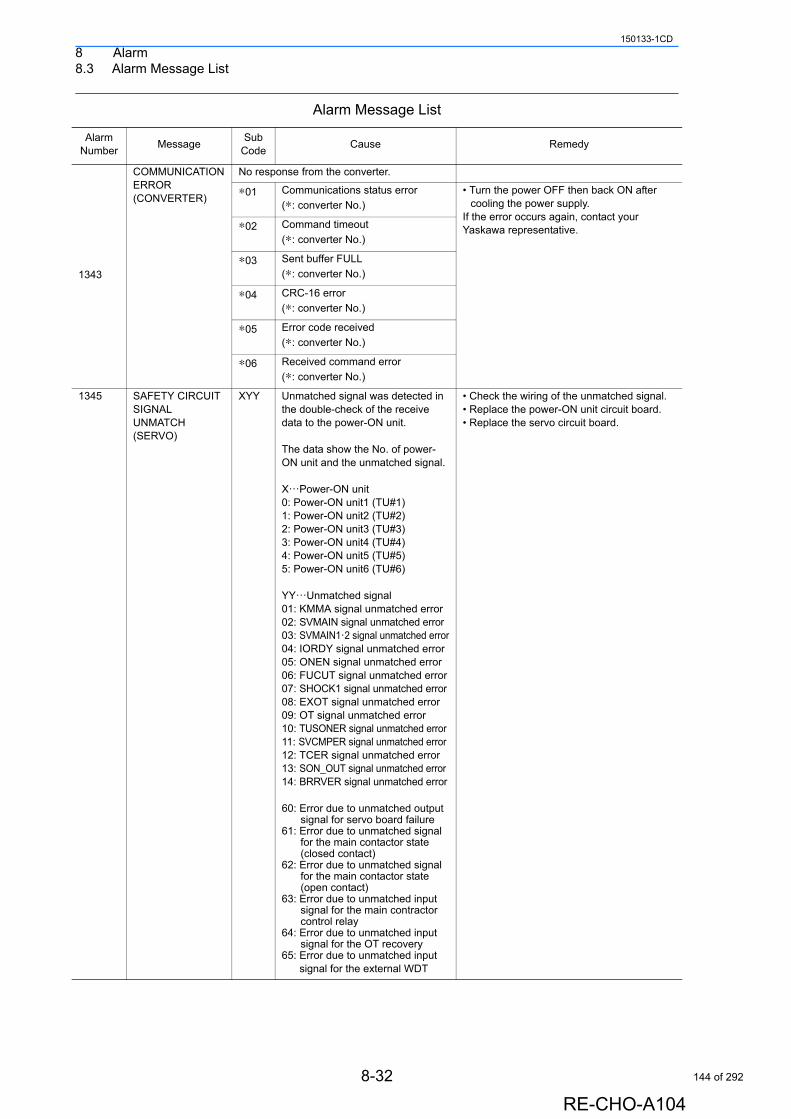
8 Alarm8.3 Alarm Message List
150133-1CD
1343
COMMUNICATION ERROR (CONVERTER)
No response from the converter.
∗01 Communications status error
(∗: converter No.)
• Turn the power OFF then back ON after cooling the power supply.
If the error occurs again, contact your Yaskawa representative.∗02 Command timeout
(∗: converter No.)
∗03 Sent buffer FULL
(∗: converter No.)
∗04 CRC-16 error
(∗: converter No.)
∗05 Error code received
(∗: converter No.)
∗06 Received command error
(∗: converter No.)
1345 SAFETY CIRCUIT SIGNAL UNMATCH (SERVO)
XYY Unmatched signal was detected in the double-check of the receive data to the power-ON unit.
The data show the No. of power-ON unit and the unmatched signal.
X···Power-ON unit0: Power-ON unit1 (TU#1)1: Power-ON unit2 (TU#2)2: Power-ON unit3 (TU#3)3: Power-ON unit4 (TU#4)4: Power-ON unit5 (TU#5)5: Power-ON unit6 (TU#6)
YY···Unmatched signal01: KMMA signal unmatched error02: SVMAIN signal unmatched error03: SVMAIN1·2 signal unmatched error04: IORDY signal unmatched error05: ONEN signal unmatched error06: FUCUT signal unmatched error07: SHOCK1 signal unmatched error08: EXOT signal unmatched error09: OT signal unmatched error10: TUSONER signal unmatched error11: SVCMPER signal unmatched error12: TCER signal unmatched error13: SON_OUT signal unmatched error14: BRRVER signal unmatched error
60: Error due to unmatched output signal for servo board failure
61: Error due to unmatched signal for the main contactor state (closed contact)
62: Error due to unmatched signal for the main contactor state (open contact)
63: Error due to unmatched input signal for the main contractor control relay
64: Error due to unmatched input signal for the OT recovery
65: Error due to unmatched input signal for the external WDT
• Check the wiring of the unmatched signal.• Replace the power-ON unit circuit board.• Replace the servo circuit board.
Alarm Message List
Alarm Number
MessageSub
CodeCause Remedy
8-32
RE-CHO-A104
144 of 292
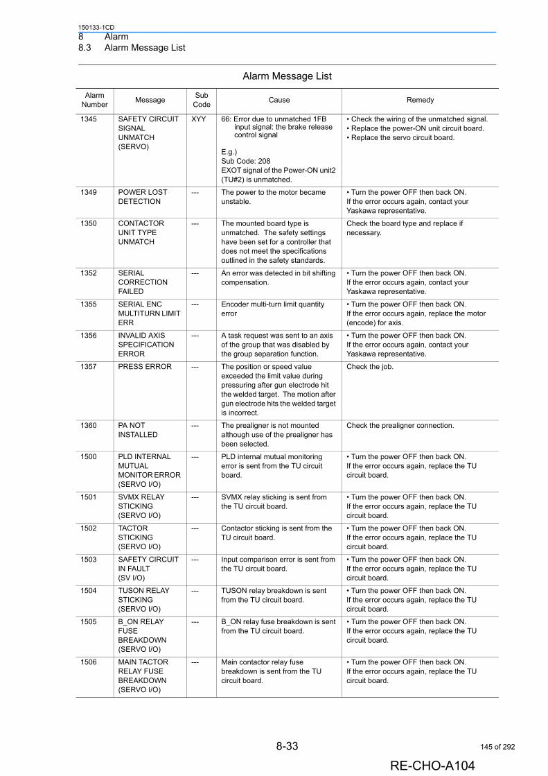
8 Alarm8.3 Alarm Message List
150133-1CD
1345 SAFETY CIRCUIT SIGNAL UNMATCH (SERVO)
XYY 66: Error due to unmatched 1FB input signal: the brake release control signal
E.g.)Sub Code: 208EXOT signal of the Power-ON unit2 (TU#2) is unmatched.
• Check the wiring of the unmatched signal.• Replace the power-ON unit circuit board.• Replace the servo circuit board.
1349 POWER LOST DETECTION
--- The power to the motor became unstable.
• Turn the power OFF then back ON.If the error occurs again, contact your Yaskawa representative.
1350 CONTACTOR UNIT TYPE UNMATCH
--- The mounted board type is unmatched. The safety settings have been set for a controller that does not meet the specifications outlined in the safety standards.
Check the board type and replace if necessary.
1352 SERIAL CORRECTION FAILED
--- An error was detected in bit shifting compensation.
• Turn the power OFF then back ON.If the error occurs again, contact your Yaskawa representative.
1355 SERIAL ENC MULTITURN LIMIT ERR
--- Encoder multi-turn limit quantity error
• Turn the power OFF then back ON. If the error occurs again, replace the motor (encode) for axis.
1356 INVALID AXIS SPECIFICATION ERROR
--- A task request was sent to an axis of the group that was disabled by the group separation function.
• Turn the power OFF then back ON.If the error occurs again, contact your Yaskawa representative.
1357 PRESS ERROR --- The position or speed value exceeded the limit value during pressuring after gun electrode hit the welded target. The motion after gun electrode hits the welded target is incorrect.
Check the job.
1360 PA NOT INSTALLED
--- The prealigner is not mounted although use of the prealigner has been selected.
Check the prealigner connection.
1500 PLD INTERNAL MUTUAL MONITOR ERROR (SERVO I/O)
--- PLD internal mutual monitoring error is sent from the TU circuit board.
• Turn the power OFF then back ON.If the error occurs again, replace the TU circuit board.
1501 SVMX RELAY STICKING (SERVO I/O)
--- SVMX relay sticking is sent from the TU circuit board.
• Turn the power OFF then back ON.If the error occurs again, replace the TU circuit board.
1502 TACTOR STICKING (SERVO I/O)
--- Contactor sticking is sent from the TU circuit board.
• Turn the power OFF then back ON.If the error occurs again, replace the TU circuit board.
1503 SAFETY CIRCUIT IN FAULT(SV I/O)
--- Input comparison error is sent from the TU circuit board.
• Turn the power OFF then back ON.If the error occurs again, replace the TU circuit board.
1504 TUSON RELAY STICKING (SERVO I/O)
--- TUSON relay breakdown is sent from the TU circuit board.
• Turn the power OFF then back ON.If the error occurs again, replace the TU circuit board.
1505 B_ON RELAY FUSE BREAKDOWN (SERVO I/O)
--- B_ON relay fuse breakdown is sent from the TU circuit board.
• Turn the power OFF then back ON.If the error occurs again, replace the TU circuit board.
1506 MAIN TACTOR RELAY FUSE BREAKDOWN(SERVO I/O)
--- Main contactor relay fuse breakdown is sent from the TU circuit board.
• Turn the power OFF then back ON.If the error occurs again, replace the TU circuit board.
Alarm Message List
Alarm Number
MessageSub
CodeCause Remedy
8-33
RE-CHO-A104
145 of 292
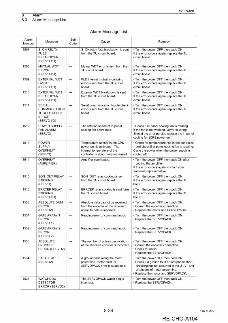
8 Alarm8.3 Alarm Message List
150133-1CD
1507 S_ON RELAY FUSE BREAKDOWN (SERVO I/O)
--- S_ON relay fuse breakdown is sent from the TU circuit board.
• Turn the power OFF then back ON.If the error occurs again, replace the TU circuit board.
1508 MUTUAL WDT ERROR (SERVO I/O)
--- Mutual WDT error is sent from the TU circuit board.
• Turn the power OFF then back ON.If the error occurs again, replace the TU circuit board.
1509 EXTERNAL WDT OVER (SERVO I/O)
--- PLD internal mutual monitoring error is sent from the TU circuit board.
• Turn the power OFF then back ON.If the error occurs again, replace the TU circuit board.
1510 EXTERNAL WDT BREAKDOWN (SERVO I/O)
--- External WDT breakdown is sent from the TU circuit board.
• Turn the power OFF then back ON.If the error occurs again, replace the TU circuit board.
1511 SERIAL COMMUNICATION TOGGLE CHECK ERROR (SERVO I/O)
--- Serial communication toggle check error is sent from the TU circuit board.
• Turn the power OFF then back ON.If the error occurs again, replace the TU circuit board.
1512 POWER SUPPLY FAN ALARM (SERVO)
--- The rotation speed of in-panel cooling fan decreased.
• Check if in-panel cooling fan is rotating.If the fan is not working, verify its wiring.Should the error persist, replace the in-panel cooling fan (CPS power unit).
1513 POWER SUPPLY OVERHEAT (SERVO)
--- Temperature sensor in the CPS power unit is activated. The internal temperature of the controller is abnormally increased.
• Check for temperature rise in the controller, and check if in-panel cooling fan is rotating.
Cycle the power when the power supply is cooled off.
1514 OVERHEAT (AMPLIFIER)
--- Amplifier overheated. • Turn the power OFF then back ON after cooling the amplifier.
If the error occurs again, contact your Yaskawa representative.
1515 SON_OUT RELAY STICKING(SERVO)
--- SON_OUT relay sticking is sent from the TU circuit board.
• Turn the power OFF then back ON.If the error occurs again, replace the TU board.
1516 BRRCER RELAY STICKING(SERVO I/O)
--- BRRCER relay sticking is sent form the TU circuit board.
• Turn the power OFF then back ON.If the error occurs again, replace the TU board.
1530 ABSOLUTE DATA ERROR(SERVO2)
--- Absolute data cannot be received from the encoder or the received absolute data is incorrect.
• Turn the power OFF then back ON.• Correct the encoder connection.• Replace the motor and SERVOPACK.
1531 GATE ARRAY 1 ERROR (SERVO 1)
--- Reading error of command input. • Turn the power OFF then back ON.• Replace the SERVOPACK.
1532 GATE ARRAY 2 ERROR (SERVO 2)
--- Reading error of command input. • Turn the power OFF then back ON.• Replace the SERVOPACK.
1533 ABSOLUTE ENCODER ERROR (SERVO2)
--- The number of pulses per rotation of the absolute encoder is incorrect.
• Turn the power OFF then back ON.• Correct the encoder connection.• Check for noise.• Replace the SERVOPACK.
1534 EARTH FAULT (SERVO2)
--- A ground fault along the motor power line, motor error, or SERVOPACK error is suspected.
• Turn the power OFF then back ON.• Check if a ground fault or interphase short-
circuiting has not occurred in the U-, V-, and W-phases of motor power line.
• Replace the motor and SERVOPACK.
1535 WATCHDOG DETECTOR ERROR (SERVO2)
--- The SERVOPACK watch dog is incorrect.
• Turn the power OFF then back ON.• Replace the SERVOPACK.
Alarm Message List
Alarm Number
MessageSub
CodeCause Remedy
8-34
RE-CHO-A104
146 of 292
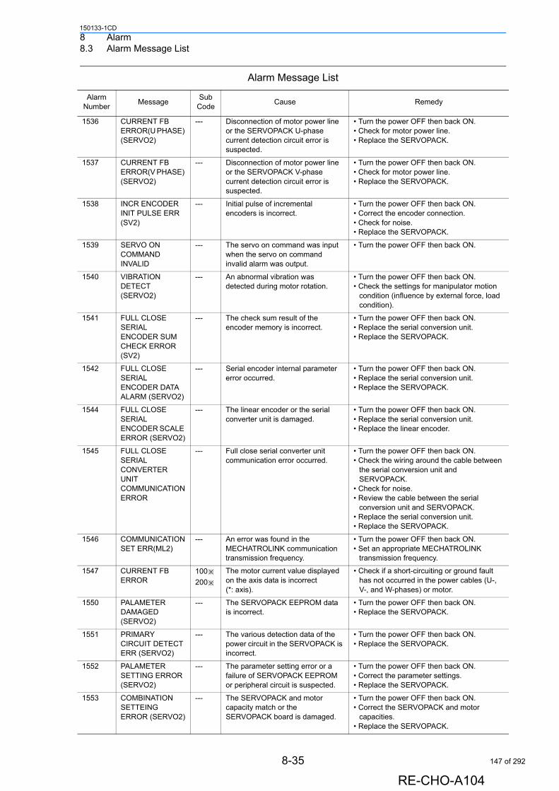
8 Alarm8.3 Alarm Message List
150133-1CD
1536 CURRENT FB ERROR(U PHASE) (SERVO2)
--- Disconnection of motor power line or the SERVOPACK U-phase current detection circuit error is suspected.
• Turn the power OFF then back ON.• Check for motor power line.• Replace the SERVOPACK.
1537 CURRENT FB ERROR(V PHASE) (SERVO2)
--- Disconnection of motor power line or the SERVOPACK V-phase current detection circuit error is suspected.
• Turn the power OFF then back ON.• Check for motor power line.• Replace the SERVOPACK.
1538 INCR ENCODER INIT PULSE ERR (SV2)
--- Initial pulse of incremental encoders is incorrect.
• Turn the power OFF then back ON.• Correct the encoder connection.• Check for noise.• Replace the SERVOPACK.
1539 SERVO ON COMMAND INVALID
--- The servo on command was input when the servo on command invalid alarm was output.
• Turn the power OFF then back ON.
1540 VIBRATION DETECT(SERVO2)
--- An abnormal vibration was detected during motor rotation.
• Turn the power OFF then back ON.• Check the settings for manipulator motion
condition (influence by external force, load condition).
1541 FULL CLOSE SERIAL ENCODER SUM CHECK ERROR (SV2)
--- The check sum result of the encoder memory is incorrect.
• Turn the power OFF then back ON.• Replace the serial conversion unit.• Replace the SERVOPACK.
1542 FULL CLOSE SERIAL ENCODER DATA ALARM (SERVO2)
--- Serial encoder internal parameter error occurred.
• Turn the power OFF then back ON.• Replace the serial conversion unit.• Replace the SERVOPACK.
1544 FULL CLOSE SERIAL ENCODER SCALE ERROR (SERVO2)
--- The linear encoder or the serial converter unit is damaged.
• Turn the power OFF then back ON.• Replace the serial conversion unit.• Replace the linear encoder.
1545 FULL CLOSE SERIAL CONVERTER UNIT COMMUNICATION ERROR
--- Full close serial converter unit communication error occurred.
• Turn the power OFF then back ON.• Check the wiring around the cable between
the serial conversion unit and SERVOPACK.
• Check for noise.• Review the cable between the serial
conversion unit and SERVOPACK.• Replace the serial conversion unit.• Replace the SERVOPACK.
1546 COMMUNICATION SET ERR(ML2)
--- An error was found in the MECHATROLINK communication transmission frequency.
• Turn the power OFF then back ON.• Set an appropriate MECHATROLINK
transmission frequency.
1547 CURRENT FB ERROR
100※200※
The motor current value displayed on the axis data is incorrect (*: axis).
• Check if a short-circuiting or ground fault has not occurred in the power cables (U-, V-, and W-phases) or motor.
1550 PALAMETER DAMAGED (SERVO2)
--- The SERVOPACK EEPROM data is incorrect.
• Turn the power OFF then back ON.• Replace the SERVOPACK.
1551 PRIMARY CIRCUIT DETECT ERR (SERVO2)
--- The various detection data of the power circuit in the SERVOPACK is incorrect.
• Turn the power OFF then back ON.• Replace the SERVOPACK.
1552 PALAMETER SETTING ERROR (SERVO2)
--- The parameter setting error or a failure of SERVOPACK EEPROM or peripheral circuit is suspected.
• Turn the power OFF then back ON.• Correct the parameter settings.• Replace the SERVOPACK.
1553 COMBINATION SETTEING ERROR (SERVO2)
--- The SERVOPACK and motor capacity match or the SERVOPACK board is damaged.
• Turn the power OFF then back ON.• Correct the SERVOPACK and motor
capacities.• Replace the SERVOPACK.
Alarm Message List
Alarm Number
MessageSub
CodeCause Remedy
8-35
RE-CHO-A104
147 of 292
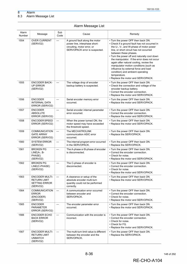
8 Alarm8.3 Alarm Message List
150133-1CD
1554 OVER CURRENT (SERVO2)
--- A ground fault along the motor power line, interphase short-circuiting, motor error, or SERVOPACK error is suspected.
• Turn the power OFF then back ON.• Check if a ground fault has not occurred in
the U-, V-, and W-phase of motor power line, or short circuit has not occurred between these phases.
• Turn the power off and naturally cool down the manipulator. If the error does not occur again after natural cooling, review the manipulator motion conditions (such as influence by external force and load condition) and ambient operating temperature.
• Replace the motor and SERVOPACK.
1555 ENCODER BACK-UP ERROR (SERVO2)
--- The voltage drop of encoder backup battery is suspected.
• Turn the power OFF then back ON.• Check the connection and voltage of the
encoder backup battery.• Correct the encoder connection.• Replace the motor and SERVOPACK.
1556 ENCODER INTERNAL DATA ERROR (SERVO2)
--- Serial encoder memory error occurred.
• Turn the power OFF then back ON.• Replace the motor and SERVOPACK.
1557 ENCODER ABSOLUTE ERROR (SERVO2)
--- Serial encoder internal parameter error occurred.
• Turn the power OFF then back ON.• Correct the encoder connection.• Replace the motor and SERVOPACK.
1558 ENCODER SPEED ERROR (SERVO2)
--- When the power turned ON, the motor speed may have exceeded the threshold speed.
• Turn the power OFF then back ON.• Replace the motor and SERVOPACK.
1559 COMMUNICATION GATE ARRAY ERROR (SERVO2)
--- The MECHATROLINK communication ASIC error occurred.
• Turn the power OFF then back ON.• Replace the SERVOPACK.
1560 SYSTEM ERROR (SERVO2)
--- The internal program error occurred in the SERVOPACK.
• Turn the power OFF then back ON.• Replace the SERVOPACK.
1561 BROKEN PG LINE(A-, B-PHASE) (SERVO2)
--- The A-phase or B-phase of encoder is disconnected.
• Turn the power OFF then back ON.• Correct the encoder connection.• Check for noise.• Replace the motor and SERVOPACK.
1562 BROKEN PG LINE(C-PHASE) (SERVO2)
--- The C-phase of encoder is disconnected.
• Turn the power OFF then back ON.• Correct the encoder connection.• Check for noise.• Replace the motor and SERVOPACK.
1563 ENCODER MULTI-RETURN LIMIT SETTING ERROR (SERVO2)
--- A clearance or setup of the absolute encoder multi-turn quantity could not be performed correctly.
• Turn the power OFF then back ON.• Replace the motor and SERVOPACK.
1564 COMMUNICATION ERROR (ENCODER) (SERVO2)
--- A communication error occurred between encoder and SERVOPACK.
• Turn the power OFF then back ON.• Correct the encoder connection.• Check for noise.• Replace the motor and SERVOPACK.
1565 ENCODER PARAMETER ERROR (SERVO2)
--- The encoder parameter error occurred.
• Turn the power OFF then back ON.• Replace the motor and SERVOPACK.
1566 ENCODER ECHO BACK ERROR (SERVO2)
--- Communication with the encoder is incorrect.
• Turn the power OFF then back ON.• Correct the encoder connection.• Check for noise.• Check for FG.• Replace the motor and SERVOPACK.
1567 ENCODER MULTI-RETURN LIMIT UNMATCH (SERVO2)
--- The multi-turn limit value is different between the encoder and the SERVOPACK.
• Turn the power OFF then back ON.• Replace the SERVOPACK.
Alarm Message List
Alarm Number
MessageSub
CodeCause Remedy
8-36
RE-CHO-A104
148 of 292

8 Alarm8.3 Alarm Message List
150133-1CD
1568 NO OPTION (SERVO2)
--- A COMl error occurred in the SERVOPACK.
• Turn the power OFF then back ON.• Replace the SERVOPACK.
1571 COMMUNICATION WATCH DOG ERROR (SERVO2)
--- WDT data updates is incorrect. • Turn the power OFF then back ON.• Replace the SERVOPACK.
1572 COMMUNICATION ERROR (SERVO2)
--- The MECHATROLINK communication error occurred.
• Turn the power OFF then back ON.• Check the wiring around the
MECHATROLINK communication cable.• Take some action against noises from the
MECHATROLINK communication cable.• Replace the SERVOPACK.
1573 SERVO PACK FAILURE (SERVO2)
--- A failure of the SERVOPACK. • Turn the power OFF then back ON.• Replace the SERVOPACK.
1576 COMMAND EXECUTE NOT READY (SERVO2)
--- A error occurred in the SERVOPACK.
• Turn the power OFF then back ON.• Replace the SERVOPACK.
1578 MOTOR LINE DISCONNECTION ALARM (SERVO2)
--- The motor power line disconnection may be the cause.
• Turn the power OFF then back ON.• Check for motor power line.• Replace the motor and SERVOPACK.
1579 MOTOR LINE DISCONNECTION ALARM (SERVO2)
--- The motor power line disconnected may be the cause.
• Turn the power OFF then back ON.• Check for motor power line.• Replace the motor and SERVOPACK.
1582 CURRENT DETECTOR ERROR (SERVO2)
--- The motor power cable is disconnected. Or the current detector of the SERVOPACK error.
• Turn the power OFF then back ON.• Check for motor power line.• Replace the motor and SERVOPACK.
1583 PHASE DETECTION ERROR (SERVO2)
--- The encoder's A, B, C phase output phases are incorrect.
• Turn the power OFF then back ON.• Correct the encoder connection.• Check for noise.• Replace the motor and SERVOPACK.
1585 MOTOR LOAD POSITION ERROR(SV2)
--- The motor load position deviation exceeded the limit.
• Turn the power OFF then back ON.• Check the connection of mechanical
combination.
1590 MC POWER SUPPLY WIRING ERR(SV2)
--- The method of the power supply to a main circuit is incorrect.
• Turn the power OFF then back ON.• Check the connection of power supply of
AC/DC.• Check the regenerative resistor.• Replace the SERVOPACK.
1592 MONITOR PLD ERROR 1(SERVO I/O)
--- External WDT failure was detected in TU.
• Turn the power OFF then back ON.If the error occurs again, replace the TU circuit board.
1593 MONITOR PLD ERROR 2(SERVO I/O)
--- External WDT timeout was detected in TU.
• Turn the power OFF then back ON.If the error occurs again, replace the TU circuit board.
1594 MONITOR PLD ERROR 3(SERVO I/O)
--- Error between WDTs was detected in TU.
• Turn the power OFF then back ON.If the error occurs again, replace the TU circuit board.
4000 MEMORY ERROR (TOOL FILE)
--- An error was detected at memory check.• The memory for the tool file is
damaged.
Initialize the tool file in maintenance mode, and then load the tool file saved in the external memory device.
4001 MEMORY ERROR (USER COORD FILE)
--- An error was detected at memory check.• The memory for the user
coordinates file is damaged.
Initialize the user coordinates file in maintenance mode, and then load the user coordinates file saved in the external memory device.
4002 MEMORY ERROR (SV MON SIGNAL FILE)
--- An error was detected at memory check.• The memory for the servo monitor
signal file is damaged.
Initialize the servo monitor signal file in maintenance mode, and then load the servo monitor signal file saved in the external memory device.
Alarm Message List
Alarm Number
MessageSub
CodeCause Remedy
8-37
RE-CHO-A104
149 of 292
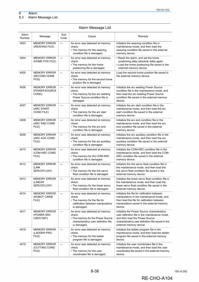
8 Alarm8.3 Alarm Message List
150133-1CD
4003 MEMORY ERROR (WEAVING FILE)
--- An error was detected at memory check.• The memory for the weaving
condition file is damaged.
Initialize the weaving condition file in maintenance mode, and then load the weaving condition file saved in the external memory device.
4004 MEMORY ERROR (HOME POS FILE)
--- An error was detected at memory check.• The memory for the home
positioning file is damaged.
• Reset the alarm, and set the home positioning data (absolute data) again.
• Load the home positioning file saved in the external memory device.
4005 MEMORY ERROR (SECOND HOME POS)
--- An error was detected at memory check.• The memory for the second home
position file is damaged.
Load the second home position file saved in the external memory device.
4006 MEMORY ERROR (POWER SOURCE COND)
--- An error was detected at memory check.• The memory for the arc welding
Power Source condition file is damaged.
Initialize the arc welding Power Source condition file in the maintenance mode, and then load the arc welding Power Source condition file saved in the external memory device.
4007 MEMORY ERROR (ARC START COND FILE)
--- An error was detected at memory check.• The memory for the arc start
condition file is damaged.
Initialize the arc start condition file in the maintenance mode, and then load the arc start condition file saved in the external memory device.
4008 MEMORY ERROR (ARC END COND FILE)
--- An error was detected at memory check.• The memory for the arc end
condition file is damaged.
Initialize the arc end condition file in the maintenance mode, and then load the arc end condition file saved in the external memory device.
4009 MEMORY ERROR (ARC AUX COND FILE)
--- An error was detected at memory check.• The memory for the arc auxiliary
condition file is damaged.
Initialize the arc auxiliary condition file in the maintenance mode, and then load the arc auxiliary condition file saved in the external memory device.
4010 MEMORY ERROR (COM-ARC COND FILE)
--- An error was detected at memory check.• The memory for the COM-ARC
condition file is damaged.
Initialize the COM-ARC condition file in the maintenance mode, and then load the COM-ARC condition file saved in the external memory device.
4012 MEMORY ERROR (LINK SERVOFLOAT)
--- An error was detected at memory check.• The memory for the link servo
float condition file is damaged.
Initialize the link servo float condition file in the maintenance mode, and then load the link servo float condition file saved in the external memory device.
4013 MEMORY ERROR (LINEAR SERVOFLOAT)
--- An error was detected at memory check.• The memory for the linear servo
float condition file is damaged.
Initialize the linear servo float condition file in the maintenance mode, and then load the linear servo float condition file saved in the external memory device.
4014 MEMORY ERROR (ROBOT CARIB FILE)
--- An error was detected at memory check.• The memory for the file for
calibration between manipulators is damaged.
Initialize the file for calibration between manipulators in the maintenance mode, and then load the file for calibration between manipulators saved in the external memory device.
4017 MEMORY ERROR (POWER SRC USER DEF)
--- An error was detected at memory check.• The memory for the Power Source
characteristics user definition file is damaged.
Initialize the Power Source characteristics user definition file in the maintenance mode, and then load the Power Source characteristics user definition file saved in the external memory device.
4018 MEMORY ERROR (LADDER PRG FILE)
--- An error was detected at memory check.• The memory for the ladder
program file is damaged.
Initialize the ladder program file in the maintenance mode, and then load the ladder program file saved in the external memory device.
4019 MEMORY ERROR (CUTTING COND FILE)
--- An error was detected at memory check.• The memory for the user
coordinates file is damaged.
Initialize the user coordinates file in the maintenance mode, and then load the user coordinates file saved in the external memory device.
Alarm Message List
Alarm Number
MessageSub
CodeCause Remedy
8-38
RE-CHO-A104
150 of 292
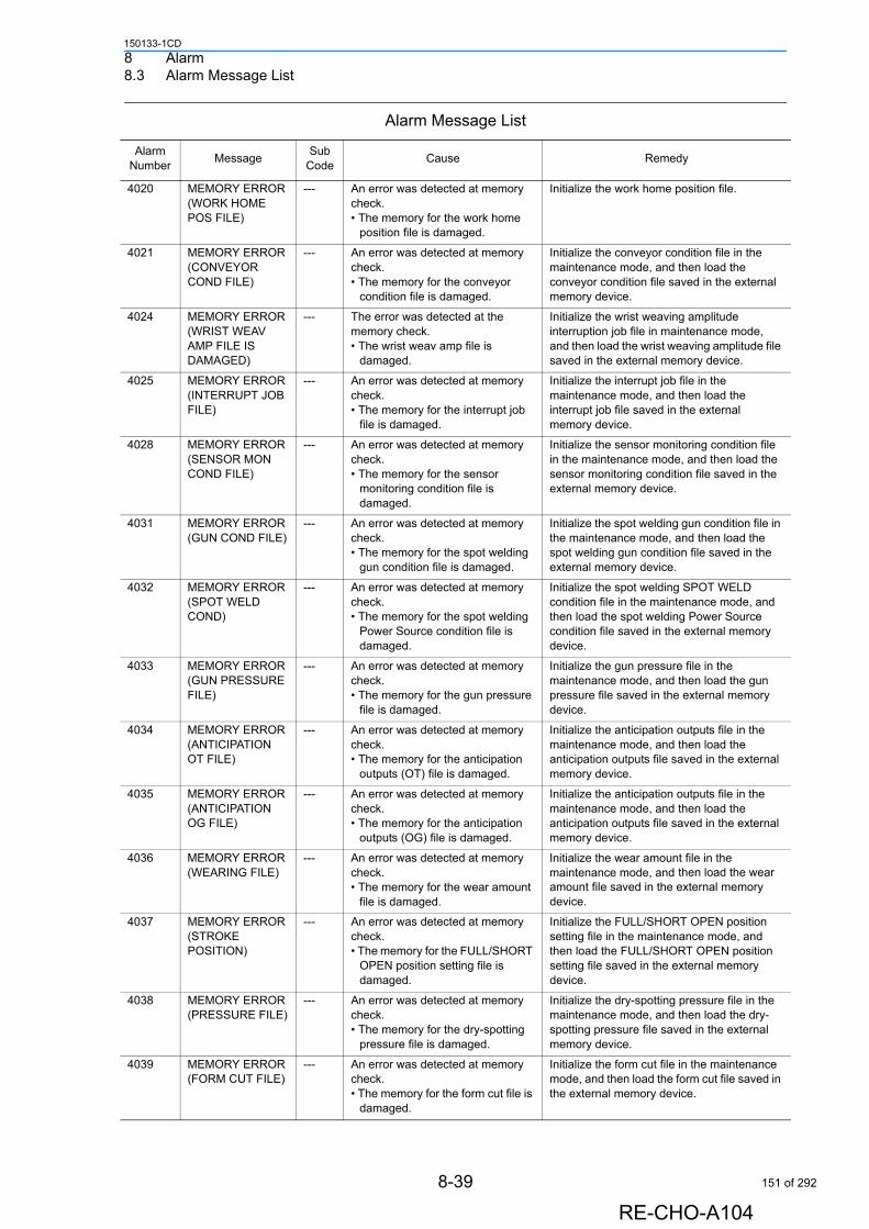
8 Alarm8.3 Alarm Message List
150133-1CD
4020 MEMORY ERROR (WORK HOME POS FILE)
--- An error was detected at memory check.• The memory for the work home
position file is damaged.
Initialize the work home position file.
4021 MEMORY ERROR (CONVEYOR COND FILE)
--- An error was detected at memory check.• The memory for the conveyor
condition file is damaged.
Initialize the conveyor condition file in the maintenance mode, and then load the conveyor condition file saved in the external memory device.
4024 MEMORY ERROR (WRIST WEAV AMP FILE IS DAMAGED)
--- The error was detected at the memory check.• The wrist weav amp file is
damaged.
Initialize the wrist weaving amplitude interruption job file in maintenance mode, and then load the wrist weaving amplitude file saved in the external memory device.
4025 MEMORY ERROR (INTERRUPT JOB FILE)
--- An error was detected at memory check.• The memory for the interrupt job
file is damaged.
Initialize the interrupt job file in the maintenance mode, and then load the interrupt job file saved in the external memory device.
4028 MEMORY ERROR (SENSOR MON COND FILE)
--- An error was detected at memory check.• The memory for the sensor
monitoring condition file is damaged.
Initialize the sensor monitoring condition file in the maintenance mode, and then load the sensor monitoring condition file saved in the external memory device.
4031 MEMORY ERROR (GUN COND FILE)
--- An error was detected at memory check.• The memory for the spot welding
gun condition file is damaged.
Initialize the spot welding gun condition file in the maintenance mode, and then load the spot welding gun condition file saved in the external memory device.
4032 MEMORY ERROR (SPOT WELD COND)
--- An error was detected at memory check.• The memory for the spot welding
Power Source condition file is damaged.
Initialize the spot welding SPOT WELD condition file in the maintenance mode, and then load the spot welding Power Source condition file saved in the external memory device.
4033 MEMORY ERROR (GUN PRESSURE FILE)
--- An error was detected at memory check.• The memory for the gun pressure
file is damaged.
Initialize the gun pressure file in the maintenance mode, and then load the gun pressure file saved in the external memory device.
4034 MEMORY ERROR (ANTICIPATION OT FILE)
--- An error was detected at memory check.• The memory for the anticipation
outputs (OT) file is damaged.
Initialize the anticipation outputs file in the maintenance mode, and then load the anticipation outputs file saved in the external memory device.
4035 MEMORY ERROR (ANTICIPATION OG FILE)
--- An error was detected at memory check.• The memory for the anticipation
outputs (OG) file is damaged.
Initialize the anticipation outputs file in the maintenance mode, and then load the anticipation outputs file saved in the external memory device.
4036 MEMORY ERROR (WEARING FILE)
--- An error was detected at memory check.• The memory for the wear amount
file is damaged.
Initialize the wear amount file in the maintenance mode, and then load the wear amount file saved in the external memory device.
4037 MEMORY ERROR (STROKE POSITION)
--- An error was detected at memory check.• The memory for the FULL/SHORT
OPEN position setting file is damaged.
Initialize the FULL/SHORT OPEN position setting file in the maintenance mode, and then load the FULL/SHORT OPEN position setting file saved in the external memory device.
4038 MEMORY ERROR (PRESSURE FILE)
--- An error was detected at memory check.• The memory for the dry-spotting
pressure file is damaged.
Initialize the dry-spotting pressure file in the maintenance mode, and then load the dry-spotting pressure file saved in the external memory device.
4039 MEMORY ERROR (FORM CUT FILE)
--- An error was detected at memory check.• The memory for the form cut file is
damaged.
Initialize the form cut file in the maintenance mode, and then load the form cut file saved in the external memory device.
Alarm Message List
Alarm Number
MessageSub
CodeCause Remedy
8-39
RE-CHO-A104
151 of 292
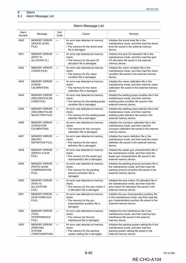
8 Alarm8.3 Alarm Message List
150133-1CD
4040 MEMORY ERROR (SHOCK LEVEL FILE)
--- An error was detected at memory check.• The memory for the shock level
file is damaged.
Initialize the shock level file in the maintenance mode, and then load the shock level file saved in the external memory device.
4041 MEMORY ERROR (SPOT IO ALLOCATE FL)
--- An error was detected at memory check.• The memory for the spot I/O
allocation file is damaged.
Initialize the spot I/O allocation file in the maintenance mode, and then load the spot I/O allocation file saved in the external memory device.
4042 MEMORY ERROR (VISION FILE)
--- An error was detected at memory check.• The memory for the vision
condition file is damaged.
Initialize the vision condition file in the maintenance mode, and then load the vision condition file saved in the external memory device.
4043 MEMORY ERROR (VISION CALIBRATION)
--- An error was detected at memory check.• The memory for the vision
calibration file is damaged.
Initialize the vision calibration file in the maintenance mode, and then load the vision calibration file saved in the external memory device.
4044 MEMORY ERROR (WELDING PULSE COND FILE)
--- An error was detected at memory check.• The memory for the welding pulse
condition file is damaged.
Initialize the welding pulse condition file in the maintenance mode, and then load the welding pulse condition file saved in the external memory device.
4045 MEMORY ERROR (WELDING PULSE SELECTION FILE)
--- An error was detected at memory check.• The memory for the welding pulse
selection file is damaged.
Initialize the welding pulse selection file in the maintenance mode, and then load the welding pulse selection file saved in the external memory device.
4046 MEMORY ERROR (CONVEYOR CALIBRATION)
--- An error was detected at memory check.• The memory for the conveyor
calibration file is damaged.
Initialize the conveyor calibration file in the maintenance mode, and then load the conveyor calibration file saved in the external memory device.
4047 MEMORY ERROR (MACRO DEFINITION FILE)
--- An error was detected at memory check.• The memory for the macro
definition file is damaged.
Initialize the macro definition file in the maintenance mode, and then load the macro definition file saved in the external memory device.
4048 MEMORY ERROR (SERVO S-GUN FILE)
--- An error was detected at memory check.• The memory for the sealer gun
characteristics file is damaged.
Initialize the sealer gun characteristics file in the maintenance mode, and then load the sealer gun characteristics file saved in the external memory device.
4049 MEMORY ERROR (PASTE QUAN COMPENSATION FILE)
--- An error was detected at memory check.• The memory for the painting
amount correction file is damaged.
Initialize the painting amount correction file in the maintenance mode, and then load the painting amount correction file saved in the external memory device.
4050 MEMORY ERROR (AXIS I/O ALLOCATION FILE)
--- An error was detected at memory check.• The memory for the axis motion I/
O allocation file is damaged.
Initialize the axis motion I/O allocation file in the maintenance mode, and then load the axis motion I/O allocation file saved in the external memory device.
4051 MEMORY ERROR (GUN COND AUX FILE)
--- An error was detected at memory check.• The memory for the gun
characteristics auxiliary file is damaged.
Initialize the gun characteristics auxiliary file in the maintenance mode, and then load the gun characteristics auxiliary file saved in the external memory device.
4052 MEMORY ERROR (TOOL INTERFERENCE FILE)
--- An error was detected at memory check.• The memory for the tool
interference file is damaged.
Initialize the tool interference file in the maintenance mode, and then load the tool interference file saved in the external memory device.
4053 MEMORY ERROR (PAINTING SYSTEM CONFIGURATION)
--- An error was detected at memory check.• The memory for the painting
system setting file is damaged.
Initialize the painting system setting file in the maintenance mode, and then load the painting system setting file saved in the external memory device.
Alarm Message List
Alarm Number
MessageSub
CodeCause Remedy
8-40
RE-CHO-A104
152 of 292
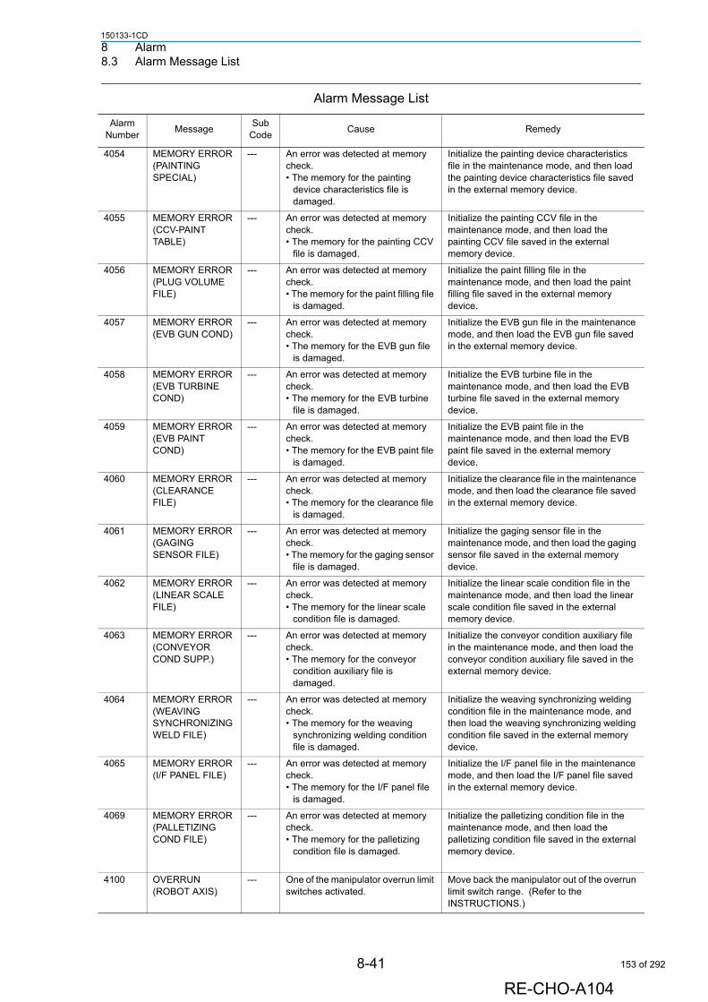
8 Alarm8.3 Alarm Message List
150133-1CD
4054 MEMORY ERROR (PAINTING SPECIAL)
--- An error was detected at memory check.• The memory for the painting
device characteristics file is damaged.
Initialize the painting device characteristics file in the maintenance mode, and then load the painting device characteristics file saved in the external memory device.
4055 MEMORY ERROR (CCV-PAINT TABLE)
--- An error was detected at memory check.• The memory for the painting CCV
file is damaged.
Initialize the painting CCV file in the maintenance mode, and then load the painting CCV file saved in the external memory device.
4056 MEMORY ERROR (PLUG VOLUME FILE)
--- An error was detected at memory check.• The memory for the paint filling file
is damaged.
Initialize the paint filling file in the maintenance mode, and then load the paint filling file saved in the external memory device.
4057 MEMORY ERROR (EVB GUN COND)
--- An error was detected at memory check.• The memory for the EVB gun file
is damaged.
Initialize the EVB gun file in the maintenance mode, and then load the EVB gun file saved in the external memory device.
4058 MEMORY ERROR (EVB TURBINE COND)
--- An error was detected at memory check.• The memory for the EVB turbine
file is damaged.
Initialize the EVB turbine file in the maintenance mode, and then load the EVB turbine file saved in the external memory device.
4059 MEMORY ERROR (EVB PAINT COND)
--- An error was detected at memory check.• The memory for the EVB paint file
is damaged.
Initialize the EVB paint file in the maintenance mode, and then load the EVB paint file saved in the external memory device.
4060 MEMORY ERROR (CLEARANCE FILE)
--- An error was detected at memory check.• The memory for the clearance file
is damaged.
Initialize the clearance file in the maintenance mode, and then load the clearance file saved in the external memory device.
4061 MEMORY ERROR (GAGING SENSOR FILE)
--- An error was detected at memory check.• The memory for the gaging sensor
file is damaged.
Initialize the gaging sensor file in the maintenance mode, and then load the gaging sensor file saved in the external memory device.
4062 MEMORY ERROR (LINEAR SCALE FILE)
--- An error was detected at memory check.• The memory for the linear scale
condition file is damaged.
Initialize the linear scale condition file in the maintenance mode, and then load the linear scale condition file saved in the external memory device.
4063 MEMORY ERROR (CONVEYOR COND SUPP.)
--- An error was detected at memory check.• The memory for the conveyor
condition auxiliary file is damaged.
Initialize the conveyor condition auxiliary file in the maintenance mode, and then load the conveyor condition auxiliary file saved in the external memory device.
4064 MEMORY ERROR (WEAVING SYNCHRONIZING WELD FILE)
--- An error was detected at memory check.• The memory for the weaving
synchronizing welding condition file is damaged.
Initialize the weaving synchronizing welding condition file in the maintenance mode, and then load the weaving synchronizing welding condition file saved in the external memory device.
4065 MEMORY ERROR(I/F PANEL FILE)
--- An error was detected at memory check.• The memory for the I/F panel file
is damaged.
Initialize the I/F panel file in the maintenance mode, and then load the I/F panel file saved in the external memory device.
4069 MEMORY ERROR(PALLETIZING COND FILE)
--- An error was detected at memory check.• The memory for the palletizing
condition file is damaged.
Initialize the palletizing condition file in the maintenance mode, and then load the palletizing condition file saved in the external memory device.
4100 OVERRUN (ROBOT AXIS)
--- One of the manipulator overrun limit switches activated.
Move back the manipulator out of the overrun limit switch range. (Refer to the INSTRUCTIONS.)
Alarm Message List
Alarm Number
MessageSub
CodeCause Remedy
8-41
RE-CHO-A104
153 of 292
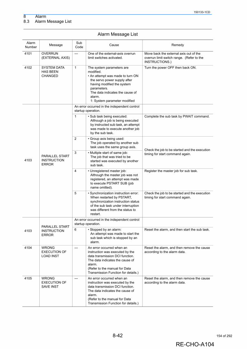
8 Alarm8.3 Alarm Message List
150133-1CD
4101 OVERRUN (EXTERNAL AXIS)
--- One of the external-axis overrun limit switches activated.
Move back the external axis out of the overrun limit switch range. (Refer to the INSTRUCTIONS.)
4102 SYSTEM DATA HAS BEEN CHANGED
1 The system parameters are modified.• An attempt was made to turn ON
the servo power supply after having modified the system parameters.The data indicates the cause of alarm.1: System parameter modified
Turn the power OFF then back ON.
4103PARALLEL START INSTRUCTION ERROR
An error occurred in the independent control startup operation.
1 • Sub task being executed:Although a job is being executed by instructed sub task, an attempt was made to execute another job by the sub task.
Complete the sub task by PWAIT command.
2 • Group axis being used:The job operated by another sub task uses the same group axis.
Check the job to be started and the execution timing for start command again.3 • Multiple start of same job:
The job that was tried to be started was executed by another sub task.
4 • Unregistered master job:Although the master job was not registered, an attempt was made to execute PSTART SUB (job name omitted).
Register the master job for sub task.
5 • Synchronization instruction error:When restarted by PSTART, synchronization instruction status of the sub task under interruption was different from the status to restart.
Check the job to be started and the execution timing for start command again.
4103PARALLEL START INSTRUCTION ERROR
An error occurred in the independent control startup operation.
6 • Stopped by an alarm:An attempt was made to start the sub task which is stopped by an alarm.
Reset the alarm, and then start the sub task.
4104 WRONG EXECUTION OF LOAD INST
--- An error occurred when an instruction was executed by the data transmission DCI function. The data indicates the cause of alarm.(Refer to the manual for Data Transmission Function for details.)
Reset the alarm, and then remove the cause according to the alarm data.
4105 WRONG EXECUTION OF SAVE INST
--- An error occurred when an instruction was executed by the data transmission DCI function. The data indicates the cause of alarm.(Refer to the manual for Data Transmission Function for details.)
Reset the alarm, and then remove the cause according to the alarm data.
Alarm Message List
Alarm Number
MessageSub
CodeCause Remedy
8-42
RE-CHO-A104
154 of 292
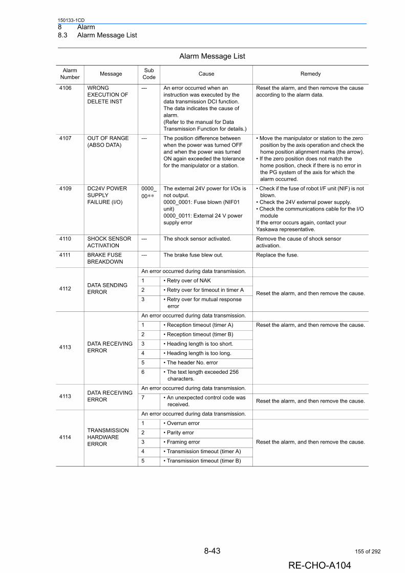
8 Alarm8.3 Alarm Message List
150133-1CD
4106 WRONG EXECUTION OF DELETE INST
--- An error occurred when an instruction was executed by the data transmission DCI function. The data indicates the cause of alarm.(Refer to the manual for Data Transmission Function for details.)
Reset the alarm, and then remove the cause according to the alarm data.
4107 OUT OF RANGE (ABSO DATA)
--- The position difference between when the power was turned OFF and when the power was turned ON again exceeded the tolerance for the manipulator or a station.
• Move the manipulator or station to the zero position by the axis operation and check the home position alignment marks (the arrow).
• If the zero position does not match the home position, check if there is no error in the PG system of the axis for which the alarm occurred.
4109 DC24V POWER SUPPLY FAILURE (I/O)
0000_
00∗∗The external 24V power for I/Os is not output.0000_0001: Fuse blown (NIF01 unit)0000_0011: External 24 V power supply error
• Check if the fuse of robot I/F unit (NIF) is not blown.
• Check the 24V external power supply.• Check the communications cable for the I/O
moduleIf the error occurs again, contact your Yaskawa representative.
4110 SHOCK SENSOR ACTIVATION
--- The shock sensor activated. Remove the cause of shock sensor activation.
4111 BRAKE FUSE BREAKDOWN
--- The brake fuse blew out. Replace the fuse.
4112DATA SENDING ERROR
An error occurred during data transmission.
1 • Retry over of NAK
Reset the alarm, and then remove the cause.2 • Retry over for timeout in timer A
3 • Retry over for mutual response error
4113DATA RECEIVING ERROR
An error occurred during data transmission.
1 • Reception timeout (timer A) Reset the alarm, and then remove the cause.
2 • Reception timeout (timer B)
3 • Heading length is too short.
4 • Heading length is too long.
5 • The header No. error
6 • The text length exceeded 256 characters.
4113DATA RECEIVING ERROR
An error occurred during data transmission.
7 • An unexpected control code was received.
Reset the alarm, and then remove the cause.
4114TRANSMISSION HARDWARE ERROR
An error occurred during data transmission.
1 • Overrun error
Reset the alarm, and then remove the cause.
2 • Parity error
3 • Framing error
4 • Transmission timeout (timer A)
5 • Transmission timeout (timer B)
Alarm Message List
Alarm Number
MessageSub
CodeCause Remedy
8-43
RE-CHO-A104
155 of 292
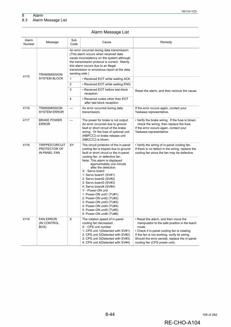
8 Alarm8.3 Alarm Message List
150133-1CD
4115TRANSMISSION SYSTEM BLOCK
An error occurred during data transmission.(This alarm occurs when received data cause inconsistency on the system although the transmission protocol is correct. Mainly, this alarm occurs due to an illegal transmission or erroneous report at the data sending side.)
1 • Received EOT while waiting ACK.
Reset the alarm, and then remove the cause.
2 • Received EOT while waiting ENQ.
3 • Received EOT before last block reception.
4 • Received codes other than EOT after last block reception.
4116 TRANSMISSION SYSTEM ERROR
--- An error occurred during data transmission.
If the error occurs again, contact your Yaskawa representative.
4117 BRAKE POWER ERROR
--- The power for brake is not output.An error occurred due to ground fault or short circuit of the brake wiring. Or the fuse of optional unit (NBP) or brake release unit (NBU) is blown.
• Verify the brake wiring. If the fuse is blown, check the wiring, then replace the fuse.
If the error occurs again, contact your Yaskawa representative.
4118 TRIPPED CIRCUIT PROTECTOR OF IN-PANEL FAN
XY The circuit protector of the in-panel cooling fan is tripped due to ground fault or short circuit or the in-panel cooling fan, or defective fan.Note: This alarm is displayed
approximately one minute after the detection.
X···Servo board1: Servo board1 (SV#1)2: Servo board2 (SV#2)3: Servo board3 (SV#3)4: Servo board4 (SV#4)Y···Power-ON unit1: Power-ON unit1 (TU#1)2: Power-ON unit2 (TU#2)3: Power-ON unit3 (TU#3)4: Power-ON unit4 (TU#4)5: Power-ON unit5 (TU#5)6: Power-ON unit6 (TU#6)
• Verify the wiring of in-panel cooling fan. If there is no defect in the wiring, replace the cooling fan since the fan may be defective.
4119 FAN ERROR (IN CONTROL BOX)
X The rotation speed of in-panel cooling fan decreased.X···CPS unit number1: CPS unit 1(Detected with SV#1)2: CPS unit 2(Detected with SV#2)3: CPS unit 3(Detected with SV#3)4: CPS unit 4(Detected with SV#4)
• Reset the alarm, and then move the manipulator to the safe position in the teach mode.
• Check if in-panel cooling fan is rotating.If the fan is not working, verify its wiring.Should the error persist, replace the in-panel cooling fan (CPS power unit).
Alarm Message List
Alarm Number
MessageSub
CodeCause Remedy
8-44
RE-CHO-A104
156 of 292
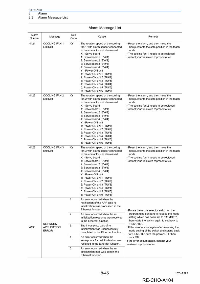
8 Alarm8.3 Alarm Message List
150133-1CD
4121 COOLING FAN 1 ERROR
XY The rotation speed of the cooling fan 1 with alarm sensor connected to the contactor unit decreased.X···Servo board1: Servo board1 (SV#1)2: Servo board2 (SV#2)3: Servo board3 (SV#3)4: Servo board4 (SV#4)Y···Power-ON unit1: Power-ON unit1 (TU#1)2: Power-ON unit2 (TU#2)3: Power-ON unit3 (TU#3)4: Power-ON unit4 (TU#4)5: Power-ON unit5 (TU#5)6: Power-ON unit6 (TU#6)
• Reset the alarm, and then move the manipulator to the safe position in the teach mode.
• The cooling fan 1 needs to be replaced. Contact your Yaskawa representative.
4122 COOLING FAN 2 ERROR
XY The rotation speed of the cooling fan 2 with alarm sensor connected to the contactor unit decreased.X···Servo board1: Servo board1 (SV#1)2: Servo board2 (SV#2)3: Servo board3 (SV#3)4: Servo board4 (SV#4)Y···Power-ON unit1: Power-ON unit1 (TU#1)2: Power-ON unit2 (TU#2)3: Power-ON unit3 (TU#3)4: Power-ON unit4 (TU#4)5: Power-ON unit5 (TU#5)6: Power-ON unit6 (TU#6)
• Reset the alarm, and then move the manipulator to the safe position in the teach mode.
• The cooling fan 2 needs to be replaced. Contact your Yaskawa representative.
4123 COOLING FAN 3 ERROR
XY The rotation speed of the cooling fan 3 with alarm sensor connected to the contactor unit decreased.X···Servo board1: Servo board1 (SV#1)2: Servo board2 (SV#2)3: Servo board3 (SV#3)4: Servo board4 (SV#4)Y···Power-ON unit1: Power-ON unit1 (TU#1)2: Power-ON unit2 (TU#2)3: Power-ON unit3 (TU#3)4: Power-ON unit4 (TU#4)5: Power-ON unit5 (TU#5)6: Power-ON unit6 (TU#6)
• Reset the alarm, and then move the manipulator to the safe position in the teach mode.
• The cooling fan 3 needs to be replaced. Contact your Yaskawa representative.
4130NETWORK APPLICATION ERROR
1 An error occurred when the notification of the APP task re-initialization was processed in the Ethernet function. • Rotate the mode selector switch on the
programming pendant to release the mode setting which has been set to "REMOTE", then rotate the switch again to set back to "REMOTE".
• If the error occurs again after releasing the mode setting of the switch and setting back to "REMOTE", turn the power OFF then back ON.
If the error occurs again, contact your Yaskawa representative.
2 An error occurred when the re-initialization response was received in the Ethernet function.
3 The incomplete task of re-initialization was unsuccessfully completed in the Ethernet function.
4 An error occurred when the semaphore for re-initialization was received in the Ethernet function.
5 An error occurred when the re-initialization mail was sent in the Ethernet function.
Alarm Message List
Alarm Number
MessageSub
CodeCause Remedy
8-45
RE-CHO-A104
157 of 292
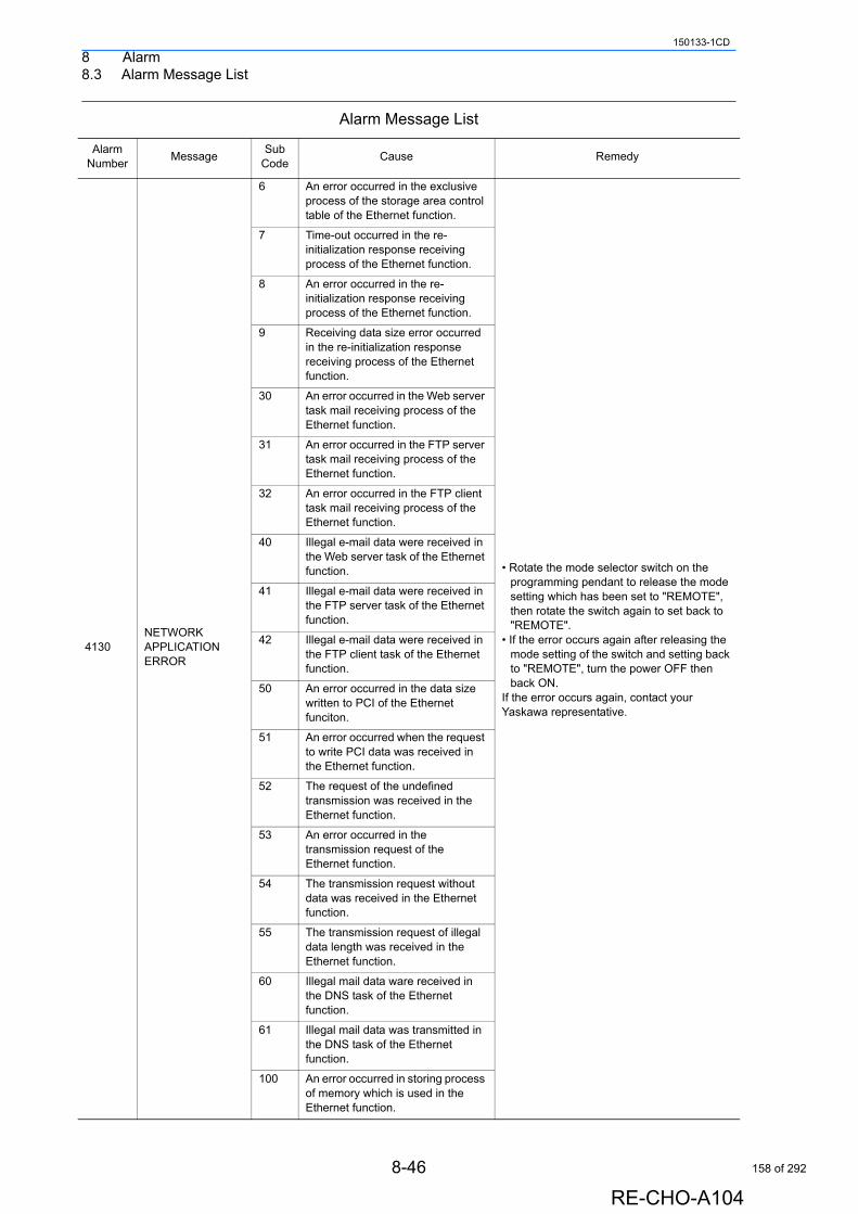
8 Alarm8.3 Alarm Message List
150133-1CD
4130NETWORK APPLICATION ERROR
6 An error occurred in the exclusive process of the storage area control table of the Ethernet function.
• Rotate the mode selector switch on the programming pendant to release the mode setting which has been set to "REMOTE", then rotate the switch again to set back to "REMOTE".
• If the error occurs again after releasing the mode setting of the switch and setting back to "REMOTE", turn the power OFF then back ON.
If the error occurs again, contact your Yaskawa representative.
7 Time-out occurred in the re-initialization response receiving process of the Ethernet function.
8 An error occurred in the re-initialization response receiving process of the Ethernet function.
9 Receiving data size error occurred in the re-initialization response receiving process of the Ethernet function.
30 An error occurred in the Web server task mail receiving process of the Ethernet function.
31 An error occurred in the FTP server task mail receiving process of the Ethernet function.
32 An error occurred in the FTP client task mail receiving process of the Ethernet function.
40 Illegal e-mail data were received in the Web server task of the Ethernet function.
41 Illegal e-mail data were received in the FTP server task of the Ethernet function.
42 Illegal e-mail data were received in the FTP client task of the Ethernet function.
50 An error occurred in the data size written to PCI of the Ethernet funciton.
51 An error occurred when the request to write PCI data was received in the Ethernet function.
52 The request of the undefined transmission was received in the Ethernet function.
53 An error occurred in the transmission request of the Ethernet function.
54 The transmission request without data was received in the Ethernet function.
55 The transmission request of illegal data length was received in the Ethernet function.
60 Illegal mail data ware received in the DNS task of the Ethernet function.
61 Illegal mail data was transmitted in the DNS task of the Ethernet function.
100 An error occurred in storing process of memory which is used in the Ethernet function.
Alarm Message List
Alarm Number
MessageSub
CodeCause Remedy
8-46
RE-CHO-A104
158 of 292
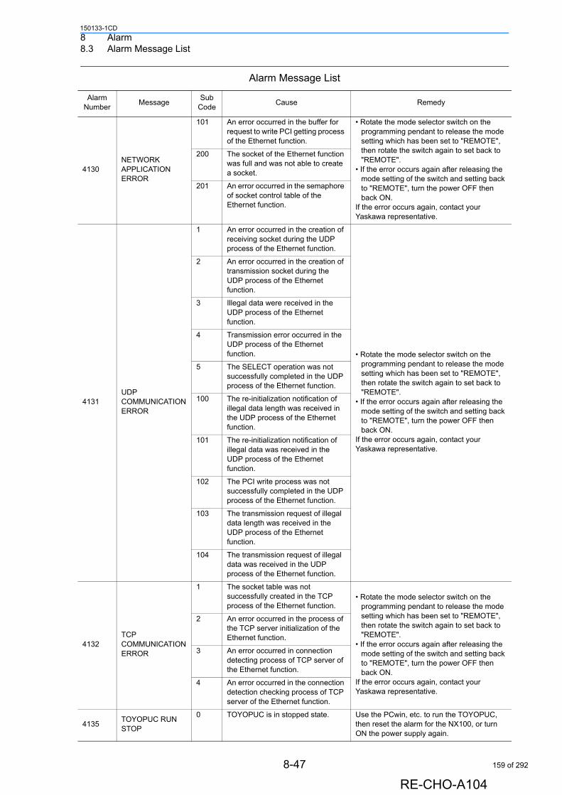
8 Alarm8.3 Alarm Message List
150133-1CD
4130NETWORK APPLICATION ERROR
101 An error occurred in the buffer for request to write PCI getting process of the Ethernet function.
• Rotate the mode selector switch on the programming pendant to release the mode setting which has been set to "REMOTE", then rotate the switch again to set back to "REMOTE".
• If the error occurs again after releasing the mode setting of the switch and setting back to "REMOTE", turn the power OFF then back ON.
If the error occurs again, contact your Yaskawa representative.
200 The socket of the Ethernet function was full and was not able to create a socket.
201 An error occurred in the semaphore of socket control table of the Ethernet function.
4131UDP COMMUNICATION ERROR
1 An error occurred in the creation of receiving socket during the UDP process of the Ethernet function.
• Rotate the mode selector switch on the programming pendant to release the mode setting which has been set to "REMOTE", then rotate the switch again to set back to "REMOTE".
• If the error occurs again after releasing the mode setting of the switch and setting back to "REMOTE", turn the power OFF then back ON.
If the error occurs again, contact your Yaskawa representative.
2 An error occurred in the creation of transmission socket during the UDP process of the Ethernet function.
3 Illegal data were received in the UDP process of the Ethernet function.
4 Transmission error occurred in the UDP process of the Ethernet function.
5 The SELECT operation was not successfully completed in the UDP process of the Ethernet function.
100 The re-initialization notification of illegal data length was received in the UDP process of the Ethernet function.
101 The re-initialization notification of illegal data was received in the UDP process of the Ethernet function.
102 The PCI write process was not successfully completed in the UDP process of the Ethernet function.
103 The transmission request of illegal data length was received in the UDP process of the Ethernet function.
104 The transmission request of illegal data was received in the UDP process of the Ethernet function.
4132TCP COMMUNICATION ERROR
1 The socket table was not successfully created in the TCP process of the Ethernet function.
• Rotate the mode selector switch on the programming pendant to release the mode setting which has been set to "REMOTE", then rotate the switch again to set back to "REMOTE".
• If the error occurs again after releasing the mode setting of the switch and setting back to "REMOTE", turn the power OFF then back ON.
If the error occurs again, contact your Yaskawa representative.
2 An error occurred in the process of the TCP server initialization of the Ethernet function.
3 An error occurred in connection detecting process of TCP server of the Ethernet function.
4 An error occurred in the connection detection checking process of TCP server of the Ethernet function.
4135TOYOPUC RUN STOP
0 TOYOPUC is in stopped state. Use the PCwin, etc. to run the TOYOPUC, then reset the alarm for the NX100, or turn ON the power supply again.
Alarm Message List
Alarm Number
MessageSub
CodeCause Remedy
8-47
RE-CHO-A104
159 of 292
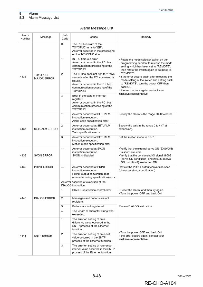
8 Alarm8.3 Alarm Message List
150133-1CD
4136TOYOPUC MAJOR ERROR
0 The PCI bus state of the TOYOPUC turns to "ER".An error occurred in the processing on the TOYOPUC side.
• Rotate the mode selector switch on the programming pendant to release the mode setting which has been set to "REMOTE", then rotate the switch again to set back to "REMOTE".
• If the error occurs again after releasing the mode setting of the switch and setting back to "REMOTE", turn the power OFF then back ON.
If the error occurs again, contact your Yaskawa representative.
1 INTRB time-out errorAn error occurred in the PCI bus communication processing of the TOYOPUC.
2 The INTPC does not turn to "1" five seconds after the PCI command is issued.An error occurred in the PCI bus communication processing of the TOYOPUC.
3 Error in the state of interrupt register1An error occurred in the PCI bus communication processing of the TOYOPUC.
4137 SETUALM ERROR
1 An error occurred at SETUALM instruction execution.Alarm code specification error
Specify the alarm in the range 8000 to 8999.
2 An error occurred at SETUALM instruction execution.Task specification error
Specify the task in the range 0 to 4 (7 at expansion).
3 An error occurred at SETUALM instruction execution.Motion mode specification error
Set the motion mode to 0 or 1.
4138 SVON ERROR
--- An error occurred at SVON instruction execution.SVON is disabled.
• Verify that the external servo ON (EXSVON) is short-circuited.
• Verify that the concurrent I/O signal #80031 (servo ON condition1) and #80033 (servo ON condition2) are turned ON.
4139 PRINT ERROR --- An error occurred at PRINT instruction execution.PRINT output conversion spec (character string specification) error
Review the PRINT output conversion spec (character string specification).
4140 DIALOG ERROR
An error occurred at execution of the DIALOG instruction.
1 DIALOG instruction control error • Reset the alarm, and then try again.• Turn the power OFF and back ON.
2 Messages and buttons are not registere.
Review DIALOG instruction.3 Buttons are not registered.
4 The length of character string was exceeded.
4141 SNTP ERROR
1 The error on setting of time difference value occurred in the SNTP process of the Ethernet function.
• Turn the power OFF and back ON.If the error occurs again, contact your Yaskawa representative.
2 The error on setting of time-out value occurred in the SNTP process of the Ethernet function.
3 The error on setting of reference interval value occurred in the SNTP process of the Ethernet function.
Alarm Message List
Alarm Number
MessageSub
CodeCause Remedy
8-48
RE-CHO-A104
160 of 292
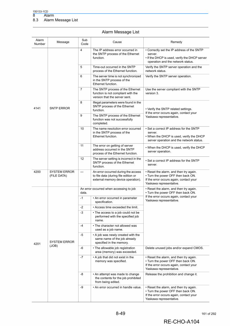
8 Alarm8.3 Alarm Message List
150133-1CD
4141 SNTP ERROR
4 The IP address error occurred in the SNTP process of the Ethernet function.
• Correctly set the IP address of the SNTP server.
• If the DHCP is used, verify the DHCP server operation and the network status.
5 Time-out occurred in the SNTP process of the Ethernet function.
Verify the SNTP server operation and the network status.
6 The server time is not synchronized in the SNTP process of the Ethernet function.
Verify the SNTP server operation.
7 The SNTP process of the Ethernet function is not compliant with the version that the server sent.
Use the server compliant with the SNTP version 3.
8 Illegal parameters were found in the SNTP process of the Ethernet function. • Verify the SNTP related settings.
If the error occurs again, contact your Yaskawa representative.9 The SNTP process of the Ethernet
function was not successfully completed.
10 The name resolution error occurred in the SNTP process of the Ethernet function.
• Set a correct IP address for the SNTP server.
• When the DHCP is used, verify the DHCP server operation and the network status.
11 The error on getting of server address occurred in the SNTP process of the Ethernet function.
• When the DHCP is used, verify the DHCP server operation.
12 The server setting is incorrect in the SNTP process of the Ethernet function.
• Set a correct IP address for the SNTP server.
4200 SYSTEM ERROR (FILE DATA)
--- An error occurred during the access to file data (during file edition or external memory device operation).
• Reset the alarm, and then try again. • Turn the power OFF then back ON. If the error occurs again, contact your Yaskawa representative.
4201SYSTEM ERROR (JOB)
An error occurred when accessing to job data.
• Reset the alarm, and then try again.• Turn the power OFF then back ON.If the error occurs again, contact your Yaskawa representative.
-1 • An error occurred in parameter specification.
-2 • Access time exceeded the limit.
-3 • The access to a job could not be performed with the specified job name.
-4 • The character not allowed was used as a job name.
-5 • A job was newly created with the same name of the job already specified in the memory.
-6 • The allowable job registration area (memory) was exceeded.
Delete unused jobs and/or expand CMOS.
-7 • A job that did not exist in the memory was specified.
• Reset the alarm, and then try again.• Turn the power OFF then back ON.If the error occurs again, contact your Yaskawa representative.
-8 • An attempt was made to change the contents for the job prohibited from being edited.
Release the prohibition and change it.
-9 • An error occurred in handle value. • Reset the alarm, and then try again.• Turn the power OFF then back ON.If the error occurs again, contact your Yaskawa representative.
Alarm Message List
Alarm Number
MessageSub
CodeCause Remedy
8-49
RE-CHO-A104
161 of 292
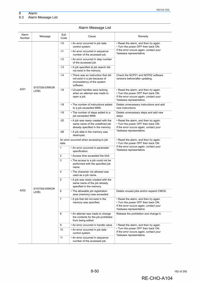
8 Alarm8.3 Alarm Message List
150133-1CD
4201SYSTEM ERROR (JOB)
-10 • An error occurred in job data control system.
• Reset the alarm, and then try again.• Turn the power OFF then back ON.If the error occurs again, contact your Yaskawa representative.
-11 • An error occurred in sequence number of the accessed job.
-12 • An error occurred in step number of the accessed job.
-13 • A job specified at job search did not exist in the memory.
-14 • There was an instruction that did not exist in a job because of inconsistency of the system software.
Check the NCP01 and NCP02 software versions before/after updating.
-16 • Unused handles were lacking when an attempt was made to open a job.
• Reset the alarm, and then try again.• Turn the power OFF then back ON.If the error occurs again, contact your Yaskawa representative.
-18 • The number of instructions added to a job exceeded 9999.
Delete unnecessary instructions and add new instructions.
-19 • The number of steps added to a job exceeded 9999.
Delete unnecessary steps and add new steps.
-20 • A job was newly created with the same name of the undefined job already specified in the memory.
• Reset the alarm, and then try again.• Turn the power OFF then back ON.If the error occurs again, contact your Yaskawa representative.-99 • A job data in the memory was
destroyed.
4202SYSTEM ERROR (JOB)
An error occurred when accessing to job data.
• Reset the alarm, and then try again.• Turn the power OFF then back ON. If the error occurs again, contact your Yaskawa representative.
1 • An error occurred in parameter specification.
2 • Access time exceeded the limit.
3 • The access to a job could not be performed with the specified job name.
4 • The character not allowed was used as a job name.
5 • A job was newly created with the same name of the job already specified in the memory.
6 • The allowable job registration area (memory) was exceeded.
Delete unused jobs and/or expand CMOS.
7 • A job that did not exist in the memory was specified.
• Reset the alarm, and then try again.• Turn the power OFF then back ON.If the error occurs again, contact your Yaskawa representative.
8 • An attempt was made to change the contents for the job prohibited from being edited.
Release the prohibition and change it.
9 • An error occurred in handle value. • Reset the alarm, and then try again.• Turn the power OFF then back ON.If the error occurs again, contact your Yaskawa representative.
10 • An error occurred in job data control system.
11 • An error occurred in sequence number of the accessed job.
Alarm Message List
Alarm Number
MessageSub
CodeCause Remedy
8-50
RE-CHO-A104
162 of 292
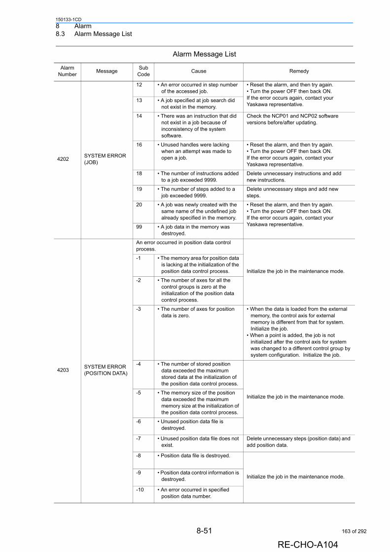
8 Alarm8.3 Alarm Message List
150133-1CD
4202SYSTEM ERROR (JOB)
12 • An error occurred in step number of the accessed job.
• Reset the alarm, and then try again.• Turn the power OFF then back ON.If the error occurs again, contact your Yaskawa representative.
13 • A job specified at job search did not exist in the memory.
14 • There was an instruction that did not exist in a job because of inconsistency of the system software.
Check the NCP01 and NCP02 software versions before/after updating.
16 • Unused handles were lacking when an attempt was made to open a job.
• Reset the alarm, and then try again.• Turn the power OFF then back ON.If the error occurs again, contact your Yaskawa representative.
18 • The number of instructions added to a job exceeded 9999.
Delete unnecessary instructions and add new instructions.
19 • The number of steps added to a job exceeded 9999.
Delete unnecessary steps and add new steps.
20 • A job was newly created with the same name of the undefined job already specified in the memory.
• Reset the alarm, and then try again.• Turn the power OFF then back ON.If the error occurs again, contact your Yaskawa representative.99 • A job data in the memory was
destroyed.
4203SYSTEM ERROR (POSITION DATA)
An error occurred in position data control process.
Initialize the job in the maintenance mode.
-1 • The memory area for position data is lacking at the initialization of the position data control process.
-2 • The number of axes for all the control groups is zero at the initialization of the position data control process.
-3 • The number of axes for position data is zero.
• When the data is loaded from the external memory, the control axis for external memory is different from that for system. Initialize the job.
• When a point is added, the job is not initialized after the control axis for system was changed to a different control group by system configuration. Initialize the job.
-4 • The number of stored position data exceeded the maximum stored data at the initialization of the position data control process.
Initialize the job in the maintenance mode.-5 • The memory size of the position
data exceeded the maximum memory size at the initialization of the position data control process.
-6 • Unused position data file is destroyed.
-7 • Unused position data file does not exist.
Delete unnecessary steps (position data) and add position data.
-8 • Position data file is destroyed.
Initialize the job in the maintenance mode.-9 • Position data control information is
destroyed.
-10 • An error occurred in specified position data number.
Alarm Message List
Alarm Number
MessageSub
CodeCause Remedy
8-51
RE-CHO-A104
163 of 292
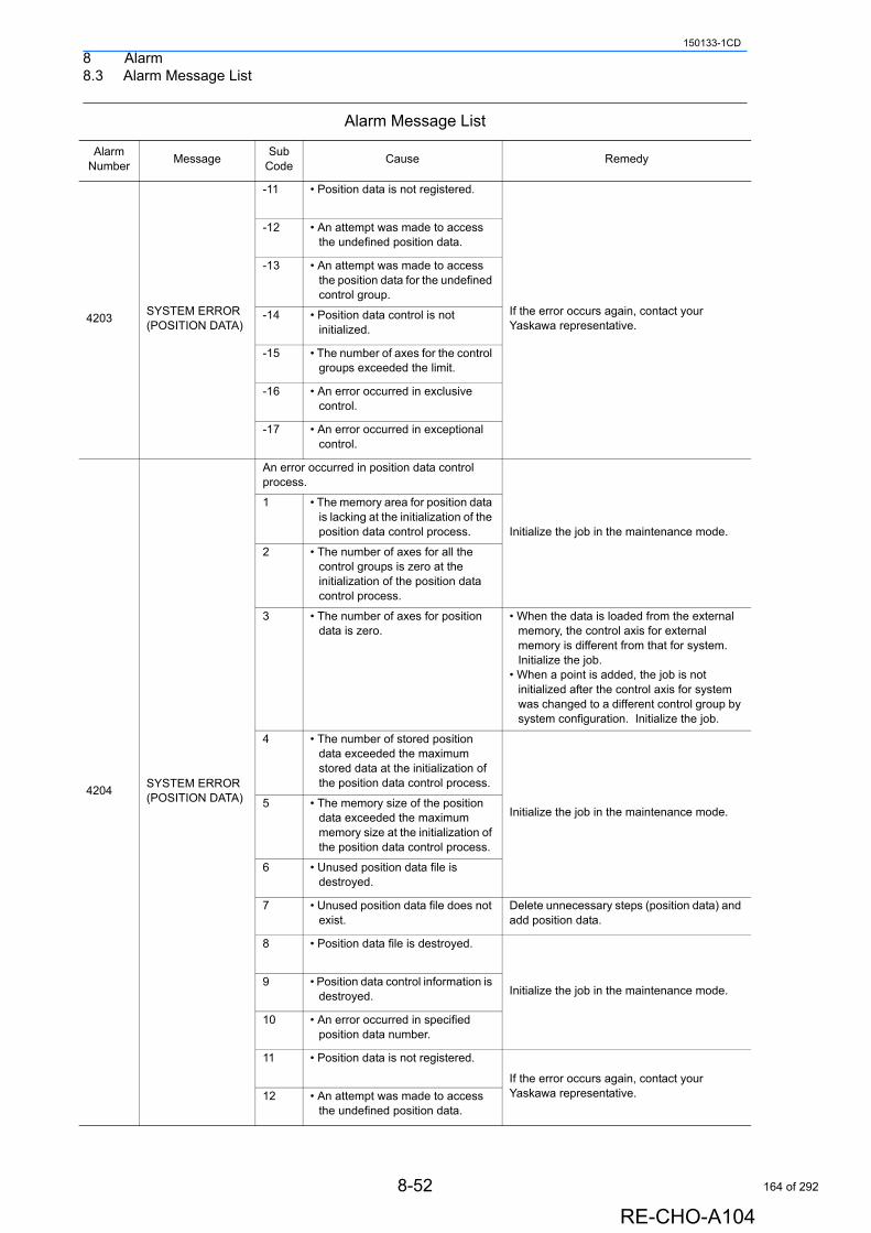
8 Alarm8.3 Alarm Message List
150133-1CD
4203SYSTEM ERROR (POSITION DATA)
-11 • Position data is not registered.
If the error occurs again, contact your Yaskawa representative.
-12 • An attempt was made to access the undefined position data.
-13 • An attempt was made to access the position data for the undefined control group.
-14 • Position data control is not initialized.
-15 • The number of axes for the control groups exceeded the limit.
-16 • An error occurred in exclusive control.
-17 • An error occurred in exceptional control.
4204SYSTEM ERROR (POSITION DATA)
An error occurred in position data control process.
Initialize the job in the maintenance mode.
1 • The memory area for position data is lacking at the initialization of the position data control process.
2 • The number of axes for all the control groups is zero at the initialization of the position data control process.
3 • The number of axes for position data is zero.
• When the data is loaded from the external memory, the control axis for external memory is different from that for system. Initialize the job.
• When a point is added, the job is not initialized after the control axis for system was changed to a different control group by system configuration. Initialize the job.
4 • The number of stored position data exceeded the maximum stored data at the initialization of the position data control process.
Initialize the job in the maintenance mode.5 • The memory size of the position
data exceeded the maximum memory size at the initialization of the position data control process.
6 • Unused position data file is destroyed.
7 • Unused position data file does not exist.
Delete unnecessary steps (position data) and add position data.
8 • Position data file is destroyed.
Initialize the job in the maintenance mode.9 • Position data control information is
destroyed.
10 • An error occurred in specified position data number.
11 • Position data is not registered.
If the error occurs again, contact your Yaskawa representative.12 • An attempt was made to access
the undefined position data.
Alarm Message List
Alarm Number
MessageSub
CodeCause Remedy
8-52
RE-CHO-A104
164 of 292
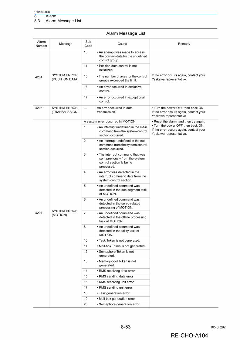
8 Alarm8.3 Alarm Message List
150133-1CD
4204SYSTEM ERROR (POSITION DATA)
13 • An attempt was made to access the position data for the undefined control group.
If the error occurs again, contact your Yaskawa representative.
14 • Position data control is not initialized.
15 • The number of axes for the control groups exceeded the limit.
16 • An error occurred in exclusive control.
17 • An error occurred in exceptional control.
4206 SYSTEM ERROR (TRANSMISSION)
--- An error occurred in data transmission.
• Turn the power OFF then back ON.If the error occurs again, contact your Yaskawa representative.
4207SYSTEM ERROR (MOTION)
A system error occurred in MOTION. • Reset the alarm, and then try again. • Turn the power OFF then back ON. If the error occurs again, contact your Yaskawa representative.
1 • An interrupt undefined in the main command from the system control section occurred.
2 • An interrupt undefined in the sub command from the system control section occurred.
3 • The interrupt command that was sent previously from the system control section is being processed.
4 • An error was detected in the interrupt command data from the system control section.
5 • An undefined command was detected in the sub segment task of MOTION.
6 • An undefined command was detected in the servo-related processing of MOTION.
7 • An undefined command was detected in the offline processing task of MOTION.
8 • An undefined command was detected in the utility task of MOTION.
10 • Task Token is not generated.
11 • Mail-box Token is not generated.
12 • Semaphore Token is not generated.
13 • Memory-pool Token is not generated.
14 • RMS receiving data error
15 • RMS sending data error
16 • RMS receiving unit error
17 • RMS sending unit error
18 • Task generation error
19 • Mail-box generation error
20 • Semaphore generation error
Alarm Message List
Alarm Number
MessageSub
CodeCause Remedy
8-53
RE-CHO-A104
165 of 292
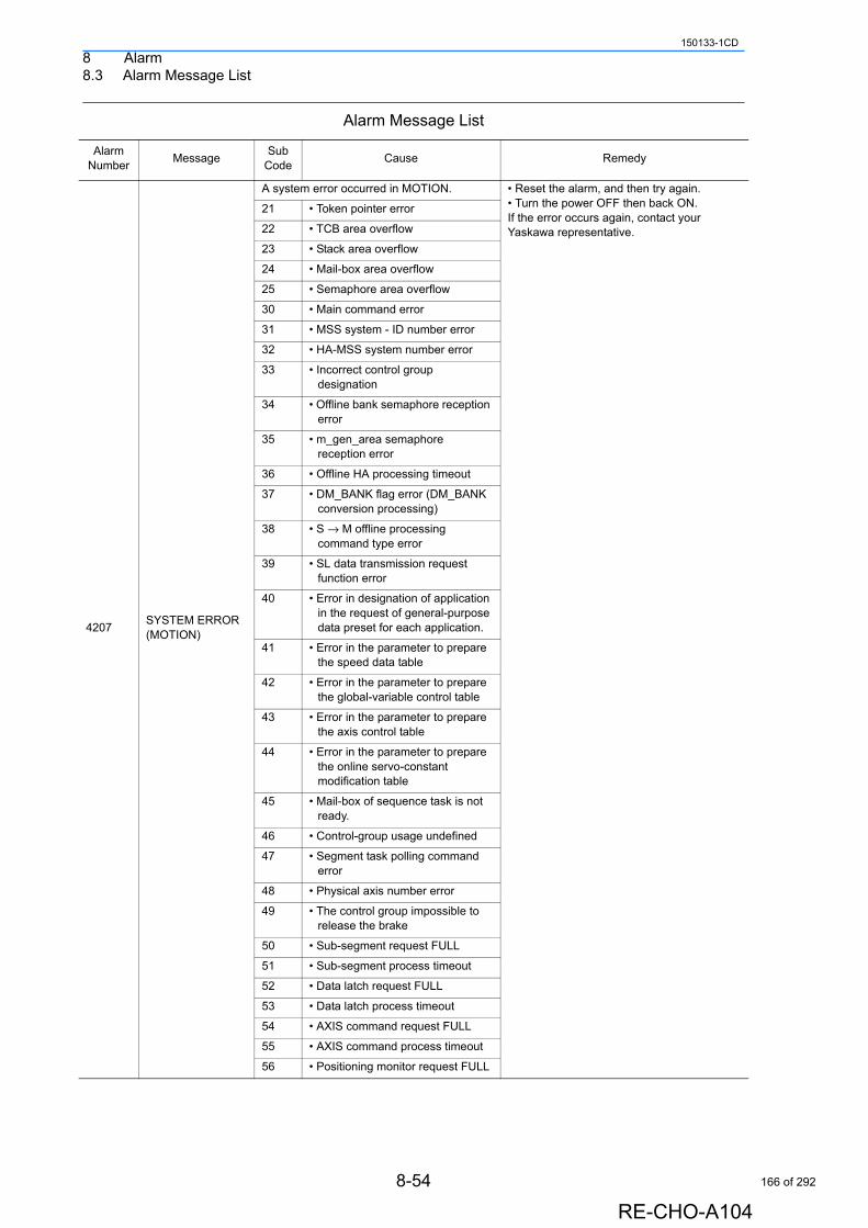
8 Alarm8.3 Alarm Message List
150133-1CD
4207SYSTEM ERROR (MOTION)
A system error occurred in MOTION. • Reset the alarm, and then try again. • Turn the power OFF then back ON. If the error occurs again, contact your Yaskawa representative.
21 • Token pointer error
22 • TCB area overflow
23 • Stack area overflow
24 • Mail-box area overflow
25 • Semaphore area overflow
30 • Main command error
31 • MSS system - ID number error
32 • HA-MSS system number error
33 • Incorrect control group designation
34 • Offline bank semaphore reception error
35 • m_gen_area semaphore reception error
36 • Offline HA processing timeout
37 • DM_BANK flag error (DM_BANK conversion processing)
38 • S → M offline processing command type error
39 • SL data transmission request function error
40 • Error in designation of application in the request of general-purpose data preset for each application.
41 • Error in the parameter to prepare the speed data table
42 • Error in the parameter to prepare the global-variable control table
43 • Error in the parameter to prepare the axis control table
44 • Error in the parameter to prepare the online servo-constant modification table
45 • Mail-box of sequence task is not ready.
46 • Control-group usage undefined
47 • Segment task polling command error
48 • Physical axis number error
49 • The control group impossible to release the brake
50 • Sub-segment request FULL
51 • Sub-segment process timeout
52 • Data latch request FULL
53 • Data latch process timeout
54 • AXIS command request FULL
55 • AXIS command process timeout
56 • Positioning monitor request FULL
Alarm Message List
Alarm Number
MessageSub
CodeCause Remedy
8-54
RE-CHO-A104
166 of 292
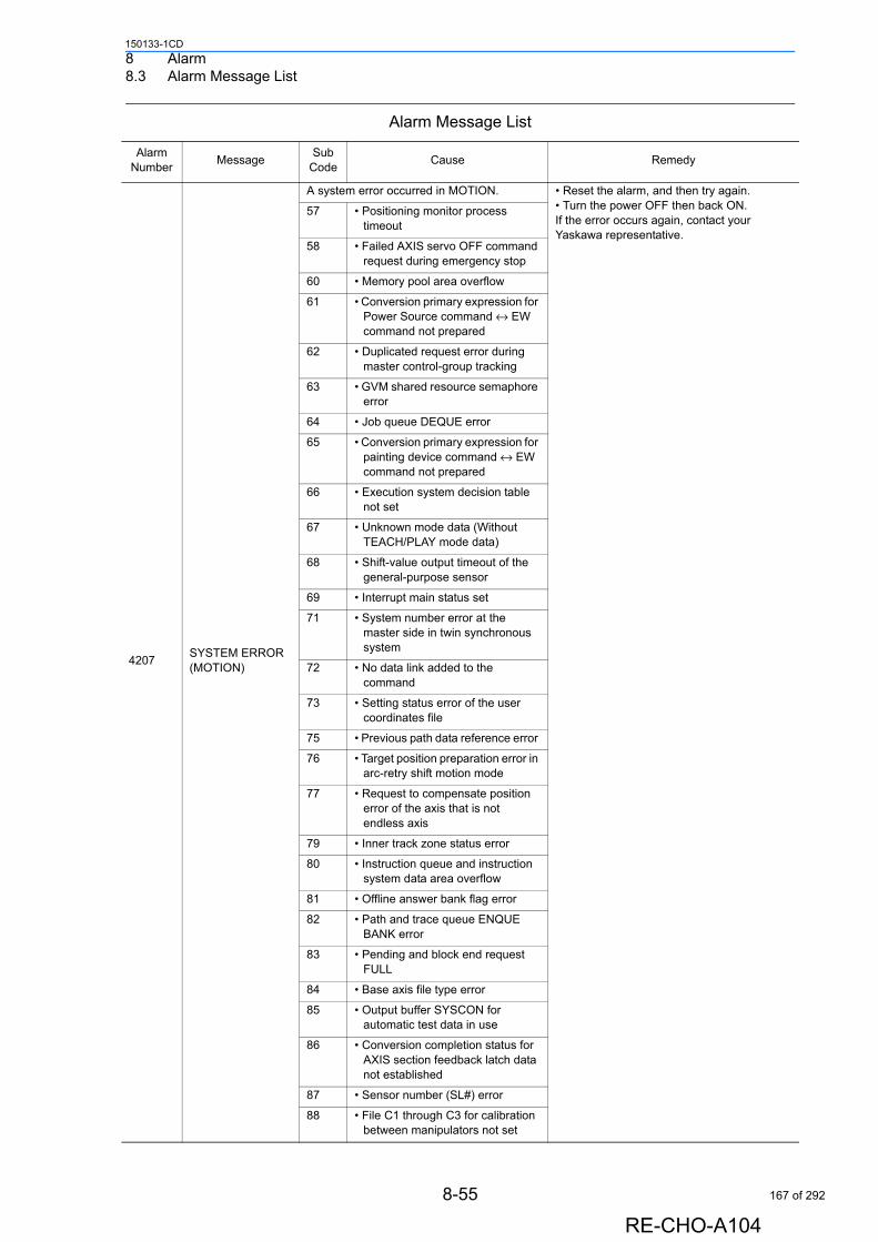
8 Alarm8.3 Alarm Message List
150133-1CD
4207SYSTEM ERROR (MOTION)
A system error occurred in MOTION. • Reset the alarm, and then try again. • Turn the power OFF then back ON. If the error occurs again, contact your Yaskawa representative.
57 • Positioning monitor process timeout
58 • Failed AXIS servo OFF command request during emergency stop
60 • Memory pool area overflow
61 • Conversion primary expression for Power Source command ↔ EW command not prepared
62 • Duplicated request error during master control-group tracking
63 • GVM shared resource semaphore error
64 • Job queue DEQUE error
65 • Conversion primary expression for painting device command ↔ EW command not prepared
66 • Execution system decision table not set
67 • Unknown mode data (Without TEACH/PLAY mode data)
68 • Shift-value output timeout of the general-purpose sensor
69 • Interrupt main status set
71 • System number error at the master side in twin synchronous system
72 • No data link added to the command
73 • Setting status error of the user coordinates file
75 • Previous path data reference error
76 • Target position preparation error in arc-retry shift motion mode
77 • Request to compensate position error of the axis that is not endless axis
79 • Inner track zone status error
80 • Instruction queue and instruction system data area overflow
81 • Offline answer bank flag error
82 • Path and trace queue ENQUE BANK error
83 • Pending and block end request FULL
84 • Base axis file type error
85 • Output buffer SYSCON for automatic test data in use
86 • Conversion completion status for AXIS section feedback latch data not established
87 • Sensor number (SL#) error
88 • File C1 through C3 for calibration between manipulators not set
Alarm Message List
Alarm Number
MessageSub
CodeCause Remedy
8-55
RE-CHO-A104
167 of 292
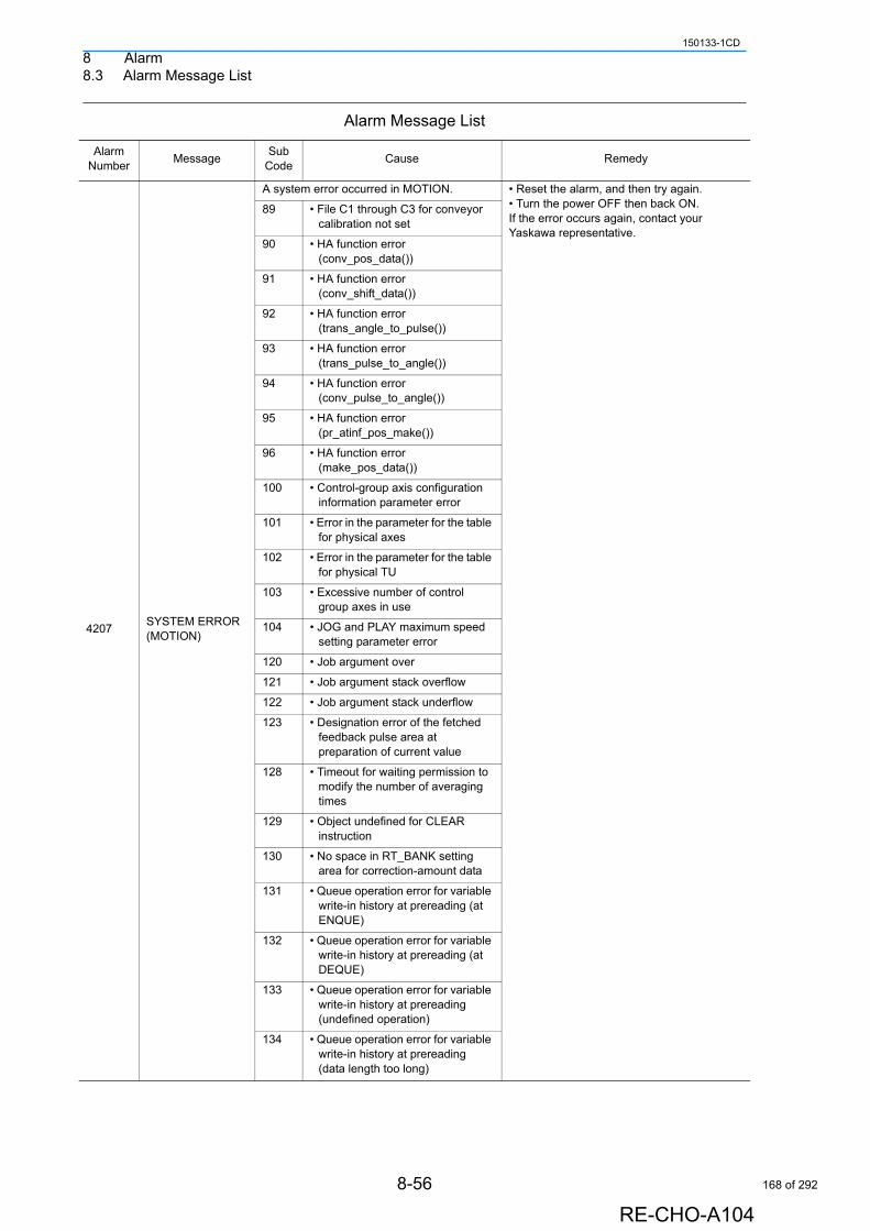
8 Alarm8.3 Alarm Message List
150133-1CD
4207SYSTEM ERROR (MOTION)
A system error occurred in MOTION. • Reset the alarm, and then try again. • Turn the power OFF then back ON. If the error occurs again, contact your Yaskawa representative.
89 • File C1 through C3 for conveyor calibration not set
90 • HA function error (conv_pos_data())
91 • HA function error (conv_shift_data())
92 • HA function error (trans_angle_to_pulse())
93 • HA function error (trans_pulse_to_angle())
94 • HA function error (conv_pulse_to_angle())
95 • HA function error (pr_atinf_pos_make())
96 • HA function error (make_pos_data())
100 • Control-group axis configuration information parameter error
101 • Error in the parameter for the table for physical axes
102 • Error in the parameter for the table for physical TU
103 • Excessive number of control group axes in use
104 • JOG and PLAY maximum speed setting parameter error
120 • Job argument over
121 • Job argument stack overflow
122 • Job argument stack underflow
123 • Designation error of the fetched feedback pulse area at preparation of current value
128 • Timeout for waiting permission to modify the number of averaging times
129 • Object undefined for CLEAR instruction
130 • No space in RT_BANK setting area for correction-amount data
131 • Queue operation error for variable write-in history at prereading (at ENQUE)
132 • Queue operation error for variable write-in history at prereading (at DEQUE)
133 • Queue operation error for variable write-in history at prereading (undefined operation)
134 • Queue operation error for variable write-in history at prereading (data length too long)
Alarm Message List
Alarm Number
MessageSub
CodeCause Remedy
8-56
RE-CHO-A104
168 of 292
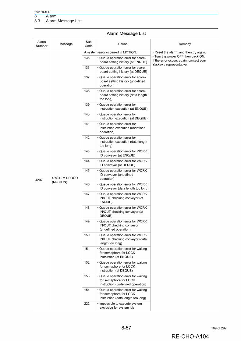
8 Alarm8.3 Alarm Message List
150133-1CD
4207SYSTEM ERROR (MOTION)
A system error occurred in MOTION. • Reset the alarm, and then try again. • Turn the power OFF then back ON. If the error occurs again, contact your Yaskawa representative.
135 • Queue operation error for score-board setting history (at ENQUE)
136 • Queue operation error for score-board setting history (at DEQUE)
137 • Queue operation error for score-board setting history (undefined operation)
138 • Queue operation error for score-board setting history (data length too long)
139 • Queue operation error for instruction execution (at ENQUE)
140 • Queue operation error for instruction execution (at DEQUE)
141 • Queue operation error for instruction execution (undefined operation)
142 • Queue operation error for instruction execution (data length too long)
143 • Queue operation error for WORK ID conveyor (at ENQUE)
144 • Queue operation error for WORK ID conveyor (at DEQUE)
145 • Queue operation error for WORK ID conveyor (undefined operation)
146 • Queue operation error for WORK ID conveyor (data length too long)
147 • Queue operation error for WORK IN/OUT checking conveyor (at ENQUE)
148 • Queue operation error for WORK IN/OUT checking conveyor (at DEQUE)
149 • Queue operation error for WORK IN/OUT checking conveyor (undefined operation)
150 • Queue operation error for WORK IN/OUT checking conveyor (data length too long)
151 • Queue operation error for waiting for semaphore for LOCK instruction (at ENQUE)
152 • Queue operation error for waiting for semaphore for LOCK instruction (at DEQUE)
153 • Queue operation error for waiting for semaphore for LOCK instruction (undefined operation)
154 • Queue operation error for waiting for semaphore for LOCK instruction (data length too long)
222 • Impossible to execute system exclusive for system job
Alarm Message List
Alarm Number
MessageSub
CodeCause Remedy
8-57
RE-CHO-A104
169 of 292
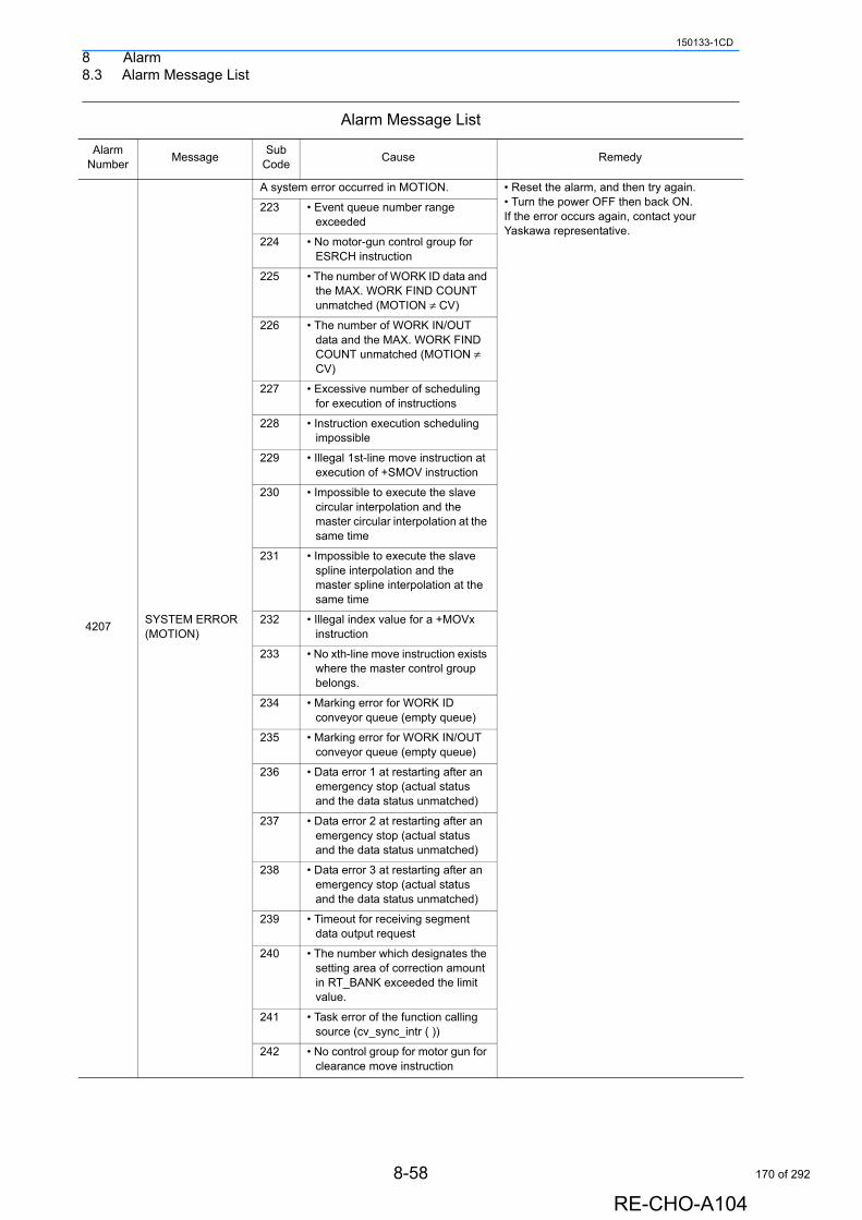
8 Alarm8.3 Alarm Message List
150133-1CD
4207SYSTEM ERROR (MOTION)
A system error occurred in MOTION. • Reset the alarm, and then try again. • Turn the power OFF then back ON. If the error occurs again, contact your Yaskawa representative.
223 • Event queue number range exceeded
224 • No motor-gun control group for ESRCH instruction
225 • The number of WORK ID data and the MAX. WORK FIND COUNT unmatched (MOTION ≠ CV)
226 • The number of WORK IN/OUT data and the MAX. WORK FIND COUNT unmatched (MOTION ≠ CV)
227 • Excessive number of scheduling for execution of instructions
228 • Instruction execution scheduling impossible
229 • Illegal 1st-line move instruction at execution of +SMOV instruction
230 • Impossible to execute the slave circular interpolation and the master circular interpolation at the same time
231 • Impossible to execute the slave spline interpolation and the master spline interpolation at the same time
232 • Illegal index value for a +MOVx instruction
233 • No xth-line move instruction exists where the master control group belongs.
234 • Marking error for WORK ID conveyor queue (empty queue)
235 • Marking error for WORK IN/OUT conveyor queue (empty queue)
236 • Data error 1 at restarting after an emergency stop (actual status and the data status unmatched)
237 • Data error 2 at restarting after an emergency stop (actual status and the data status unmatched)
238 • Data error 3 at restarting after an emergency stop (actual status and the data status unmatched)
239 • Timeout for receiving segment data output request
240 • The number which designates the setting area of correction amount in RT_BANK exceeded the limit value.
241 • Task error of the function calling source (cv_sync_intr ( ))
242 • No control group for motor gun for clearance move instruction
Alarm Message List
Alarm Number
MessageSub
CodeCause Remedy
8-58
RE-CHO-A104
170 of 292
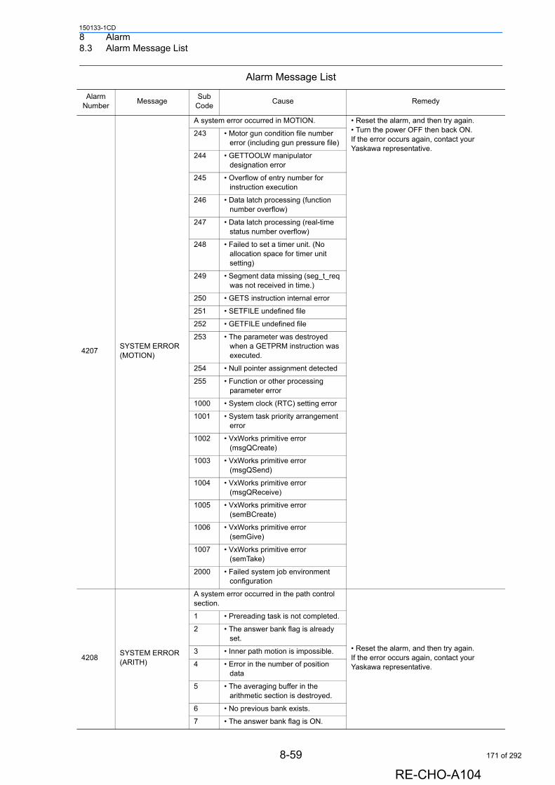
8 Alarm8.3 Alarm Message List
150133-1CD
4207SYSTEM ERROR (MOTION)
A system error occurred in MOTION. • Reset the alarm, and then try again. • Turn the power OFF then back ON. If the error occurs again, contact your Yaskawa representative.
243 • Motor gun condition file number error (including gun pressure file)
244 • GETTOOLW manipulator designation error
245 • Overflow of entry number for instruction execution
246 • Data latch processing (function number overflow)
247 • Data latch processing (real-time status number overflow)
248 • Failed to set a timer unit. (No allocation space for timer unit setting)
249 • Segment data missing (seg_t_req was not received in time.)
250 • GETS instruction internal error
251 • SETFILE undefined file
252 • GETFILE undefined file
253 • The parameter was destroyed when a GETPRM instruction was executed.
254 • Null pointer assignment detected
255 • Function or other processing parameter error
1000 • System clock (RTC) setting error
1001 • System task priority arrangement error
1002 • VxWorks primitive error (msgQCreate)
1003 • VxWorks primitive error (msgQSend)
1004 • VxWorks primitive error (msgQReceive)
1005 • VxWorks primitive error (semBCreate)
1006 • VxWorks primitive error (semGive)
1007 • VxWorks primitive error (semTake)
2000 • Failed system job environment configuration
4208SYSTEM ERROR (ARITH)
A system error occurred in the path control section.
• Reset the alarm, and then try again. If the error occurs again, contact your Yaskawa representative.
1 • Prereading task is not completed.
2 • The answer bank flag is already set.
3 • Inner path motion is impossible.
4 • Error in the number of position data
5 • The averaging buffer in the arithmetic section is destroyed.
6 • No previous bank exists.
7 • The answer bank flag is ON.
Alarm Message List
Alarm Number
MessageSub
CodeCause Remedy
8-59
RE-CHO-A104
171 of 292

8 Alarm8.3 Alarm Message List
150133-1CD
4208SYSTEM ERROR (ARITH)
A system error occurred in the path control section.
• Reset the alarm, and then try again. If the error occurs again, contact your Yaskawa representative.
8 • An error occurred in preparation of current position.
9 • Mails could not correctly be received in the current task.
10 • Spline-curve path designation error
11 • The previous bank’s prereading conversion could not correctly be completed.
12 • A manipulator designation error occurred at JOG operation using the external reference point.
13 • Designation error of cubic interference coordinates
14 • Path control position data error of prereading bank
15 • Weaving control position data error of prereading bank
16 • Station/base axis motion command error
18 • User coordinates number error
19 • Processing error in re-preparation of segment control data
20 • Prereading task not completed at master in twin synchronous system
21 • Zero division occurred at observer operation.
22 • Processing error in optimized acceleration/deceleration control
23 • Dynamic model arithmetic error
24 • Speed limit control error (excessive moment of gravity)
25 • Square root of a negative number
26 • The system number is not set at master in twin synchronous system.
27 • Designation error of control group for servo sealer gun
28 • Designation error of control condition for servo sealer gun
29 • FORMCUT internal control error
30 • Arm interference check error (radius data referencing mistake)
31 • Arm interference check error (miscalculation using direct kinematics)
32 • Arm interference check error (L-axis expansion flag setting error)
33 • Arm interference check error (check-point re-setting error)
34 • Impossible to edit the averaging buffer (zero division)
Alarm Message List
Alarm Number
MessageSub
CodeCause Remedy
8-60
RE-CHO-A104
172 of 292
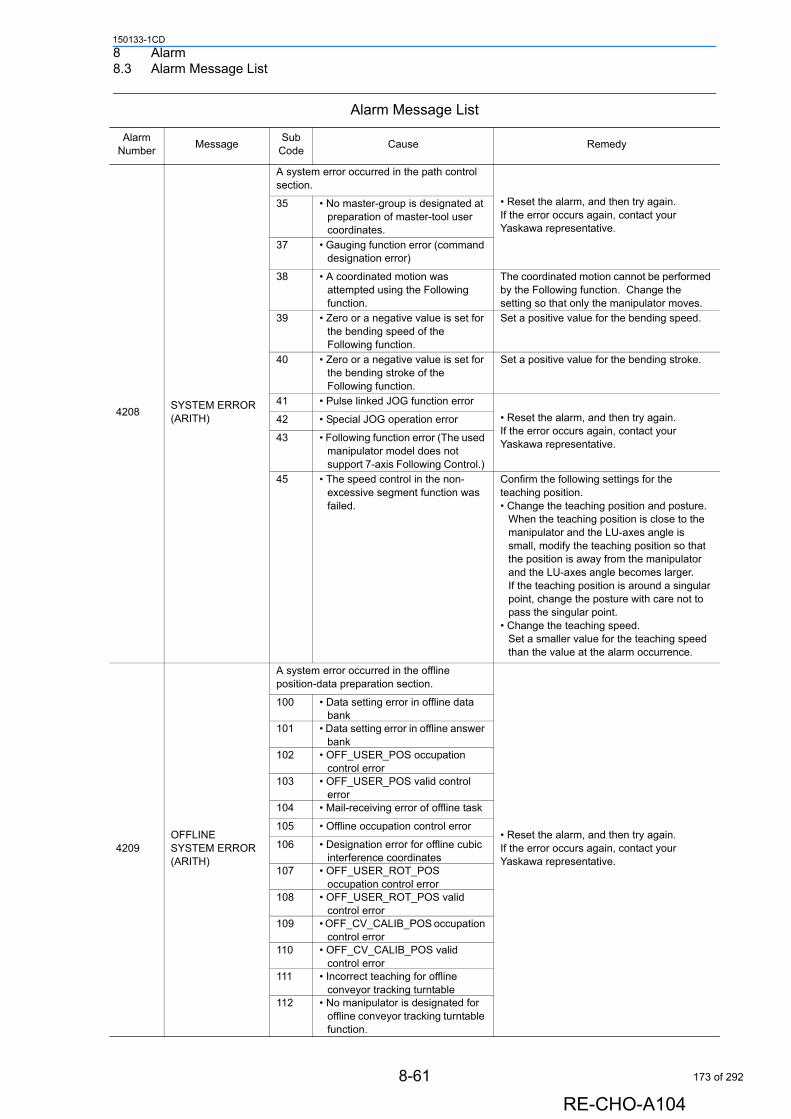
8 Alarm8.3 Alarm Message List
150133-1CD
4208SYSTEM ERROR (ARITH)
A system error occurred in the path control section.
• Reset the alarm, and then try again. If the error occurs again, contact your Yaskawa representative.
35 • No master-group is designated at preparation of master-tool user coordinates.
37 • Gauging function error (command designation error)
38 • A coordinated motion was attempted using the Following function.
The coordinated motion cannot be performed by the Following function. Change the setting so that only the manipulator moves.
39 • Zero or a negative value is set for the bending speed of the Following function.
Set a positive value for the bending speed.
40 • Zero or a negative value is set for the bending stroke of the Following function.
Set a positive value for the bending stroke.
41 • Pulse linked JOG function error
• Reset the alarm, and then try again. If the error occurs again, contact your Yaskawa representative.
42 • Special JOG operation error
43 • Following function error (The used manipulator model does not support 7-axis Following Control.)
45 • The speed control in the non-excessive segment function was failed.
Confirm the following settings for the teaching position.• Change the teaching position and posture.
When the teaching position is close to the manipulator and the LU-axes angle is small, modify the teaching position so that the position is away from the manipulator and the LU-axes angle becomes larger. If the teaching position is around a singular point, change the posture with care not to pass the singular point.
• Change the teaching speed.Set a smaller value for the teaching speed than the value at the alarm occurrence.
4209OFFLINE SYSTEM ERROR (ARITH)
A system error occurred in the offline position-data preparation section.
• Reset the alarm, and then try again. If the error occurs again, contact your Yaskawa representative.
100 • Data setting error in offline data bank
101 • Data setting error in offline answer bank
102 • OFF_USER_POS occupation control error
103 • OFF_USER_POS valid control error
104 • Mail-receiving error of offline task
105 • Offline occupation control error
106 • Designation error for offline cubic interference coordinates
107 • OFF_USER_ROT_POS occupation control error
108 • OFF_USER_ROT_POS valid control error
109 • OFF_CV_CALIB_POS occupation control error
110 • OFF_CV_CALIB_POS valid control error
111 • Incorrect teaching for offline conveyor tracking turntable
112 • No manipulator is designated for offline conveyor tracking turntable function.
Alarm Message List
Alarm Number
MessageSub
CodeCause Remedy
8-61
RE-CHO-A104
173 of 292
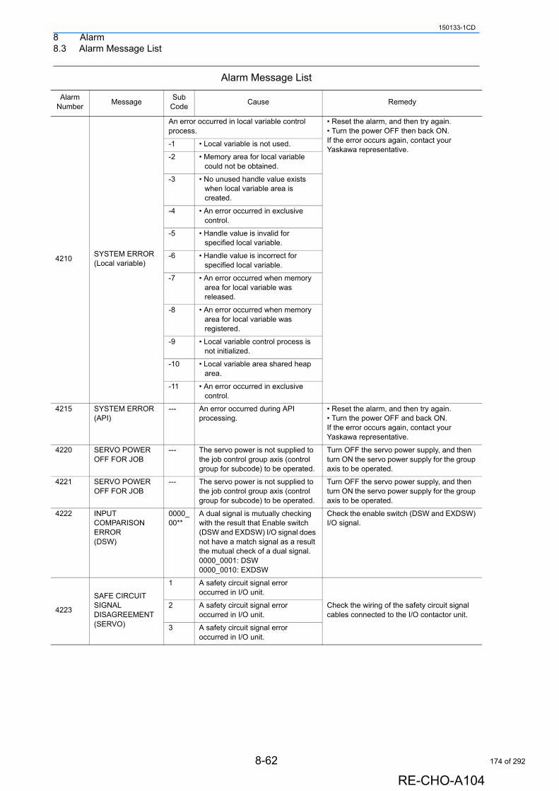
8 Alarm8.3 Alarm Message List
150133-1CD
4210SYSTEM ERROR (Local variable)
An error occurred in local variable control process.
• Reset the alarm, and then try again.• Turn the power OFF then back ON.If the error occurs again, contact your Yaskawa representative.
-1 • Local variable is not used.
-2 • Memory area for local variable could not be obtained.
-3 • No unused handle value exists when local variable area is created.
-4 • An error occurred in exclusive control.
-5 • Handle value is invalid for specified local variable.
-6 • Handle value is incorrect for specified local variable.
-7 • An error occurred when memory area for local variable was released.
-8 • An error occurred when memory area for local variable was registered.
-9 • Local variable control process is not initialized.
-10 • Local variable area shared heap area.
-11 • An error occurred in exclusive control.
4215 SYSTEM ERROR (API)
--- An error occurred during API processing.
• Reset the alarm, and then try again.• Turn the power OFF and back ON.If the error occurs again, contact your Yaskawa representative.
4220 SERVO POWER OFF FOR JOB
--- The servo power is not supplied to the job control group axis (control group for subcode) to be operated.
Turn OFF the servo power supply, and then turn ON the servo power supply for the group axis to be operated.
4221 SERVO POWER OFF FOR JOB
--- The servo power is not supplied to the job control group axis (control group for subcode) to be operated.
Turn OFF the servo power supply, and then turn ON the servo power supply for the group axis to be operated.
4222 INPUT COMPARISON ERROR (DSW)
0000_00**
A dual signal is mutually checking with the result that Enable switch (DSW and EXDSW) I/O signal does not have a match signal as a result the mutual check of a dual signal.0000_0001: DSW0000_0010: EXDSW
Check the enable switch (DSW and EXDSW) I/O signal.
4223
SAFE CIRCUIT SIGNAL DISAGREEMENT (SERVO)
1 A safety circuit signal error occurred in I/O unit.
Check the wiring of the safety circuit signal cables connected to the I/O contactor unit.
2 A safety circuit signal error occurred in I/O unit.
3 A safety circuit signal error occurred in I/O unit.
Alarm Message List
Alarm Number
MessageSub
CodeCause Remedy
8-62
RE-CHO-A104
174 of 292
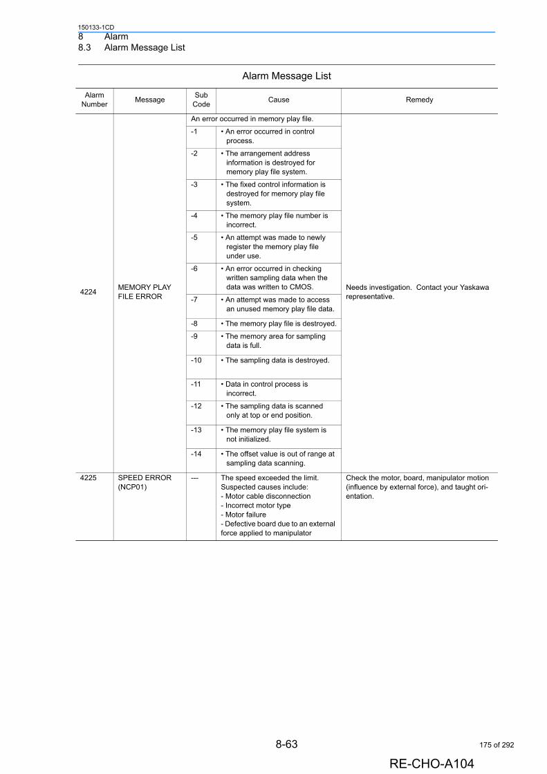
8 Alarm8.3 Alarm Message List
150133-1CD
4224MEMORY PLAY FILE ERROR
An error occurred in memory play file.
Needs investigation. Contact your Yaskawa representative.
-1 • An error occurred in control process.
-2 • The arrangement address information is destroyed for memory play file system.
-3 • The fixed control information is destroyed for memory play file system.
-4 • The memory play file number is incorrect.
-5 • An attempt was made to newly register the memory play file under use.
-6 • An error occurred in checking written sampling data when the data was written to CMOS.
-7 • An attempt was made to access an unused memory play file data.
-8 • The memory play file is destroyed.
-9 • The memory area for sampling data is full.
-10 • The sampling data is destroyed.
-11 • Data in control process is incorrect.
-12 • The sampling data is scanned only at top or end position.
-13 • The memory play file system is not initialized.
-14 • The offset value is out of range at sampling data scanning.
4225 SPEED ERROR (NCP01)
--- The speed exceeded the limit. Suspected causes include:- Motor cable disconnection- Incorrect motor type- Motor failure- Defective board due to an external force applied to manipulator
Check the motor, board, manipulator motion (influence by external force), and taught ori-entation.
Alarm Message List
Alarm Number
MessageSub
CodeCause Remedy
8-63
RE-CHO-A104
175 of 292
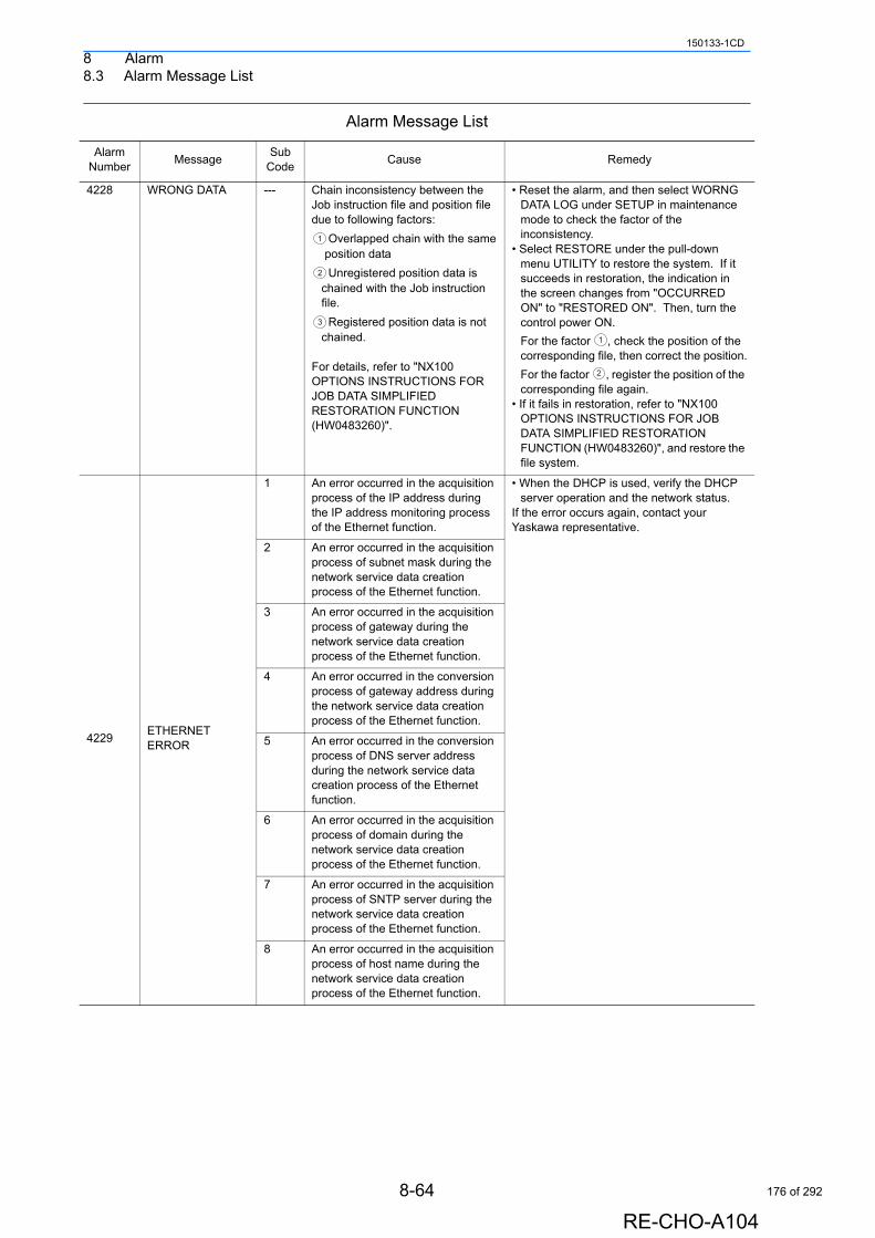
8 Alarm8.3 Alarm Message List
150133-1CD
4228 WRONG DATA --- Chain inconsistency between the Job instruction file and position file due to following factors:
Overlapped chain with the same position data
Unregistered position data is chained with the Job instruction file.
Registered position data is not chained.
For details, refer to "NX100 OPTIONS INSTRUCTIONS FOR JOB DATA SIMPLIFIED RESTORATION FUNCTION (HW0483260)".
• Reset the alarm, and then select WORNG DATA LOG under SETUP in maintenance mode to check the factor of the inconsistency.
• Select RESTORE under the pull-down menu UTILITY to restore the system. If it succeeds in restoration, the indication in the screen changes from "OCCURRED ON" to "RESTORED ON". Then, turn the control power ON.
For the factor , check the position of the corresponding file, then correct the position.
For the factor , register the position of the corresponding file again.
• If it fails in restoration, refer to "NX100 OPTIONS INSTRUCTIONS FOR JOB DATA SIMPLIFIED RESTORATION FUNCTION (HW0483260)", and restore the file system.
4229ETHERNET ERROR
1 An error occurred in the acquisition process of the IP address during the IP address monitoring process of the Ethernet function.
• When the DHCP is used, verify the DHCP server operation and the network status.
If the error occurs again, contact your Yaskawa representative.
2 An error occurred in the acquisition process of subnet mask during the network service data creation process of the Ethernet function.
3 An error occurred in the acquisition process of gateway during the network service data creation process of the Ethernet function.
4 An error occurred in the conversion process of gateway address during the network service data creation process of the Ethernet function.
5 An error occurred in the conversion process of DNS server address during the network service data creation process of the Ethernet function.
6 An error occurred in the acquisition process of domain during the network service data creation process of the Ethernet function.
7 An error occurred in the acquisition process of SNTP server during the network service data creation process of the Ethernet function.
8 An error occurred in the acquisition process of host name during the network service data creation process of the Ethernet function.
Alarm Message List
Alarm Number
MessageSub
CodeCause Remedy
1
2
3
1
2
8-64
RE-CHO-A104
176 of 292
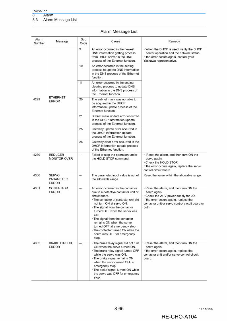
8 Alarm8.3 Alarm Message List
150133-1CD
4229ETHERNET ERROR
9 An error occurred in the newest DNS information getting process from DHCP server in the DNS process of the Ethernet function.
• When the DHCP is used, verify the DHCP server operation and the network status.
If the error occurs again, contact your Yaskawa representative.
10 An error occurred in the setting process to update DNS information in the DNS process of the Ethernet function.
11 An error occurred in the setting clearing process to update DNS information in the DNS process of the Ethernet function.
20 The subnet mask was not able to be acquired in the DHCP information update process of the Ethernet function.
21 Subnet mask update error occurred in the DHCP information update process of the Ethernet function.
25 Gateway update error occurred in the DHCP information update process of the Ethernet function.
26 Gateway clear error occurred in the DHCP information update process of the Ethernet function.
4230 REDUCER MONITOR OVER
--- Failed to stop the operation under the HOLD STOP command.
• Reset the alarm, and then turn ON the servo again.
• Check the HOLD STOP.If the error occurs again, replace the servo control circuit board.
4300 SERVO PARAMETER ERROR
--- The parameter input value is out of the allowable range.
Reset the value within the allowable range.
4301 CONTACTOR ERROR
--- An error occurred in the contactor due to a defective contactor unit or circuit board.• The contactor of contactor unit did
not turn ON at servo ON. • The signal from the contactor
turned OFF while the servo was ON.
• The signal from the contactor remains ON when the servo turned OFF at emergency stop.
• The contactor turned ON while the servo was OFF for emergency stop.
• Reset the alarm, and then turn ON the servo again.
• Check the 24-V power supply for I/O. If the error occurs again, replace the contactor unit or servo control circuit board or both.
4302 BRAKE CIRCUIT ERROR
--- • The brake relay signal did not turn ON when the servo turned ON.
• The brake relay signal turned OFF while the servo was ON.
• The brake signal remains ON when the servo turned OFF at emergency stop.
• The brake signal turned ON while the servo was OFF for emergency stop.
• Reset the alarm, and then turn ON the servo again.
If the error occurs again, replace the contactor unit and/or servo control circuit board.
Alarm Message List
Alarm Number
MessageSub
CodeCause Remedy
8-65
RE-CHO-A104
177 of 292
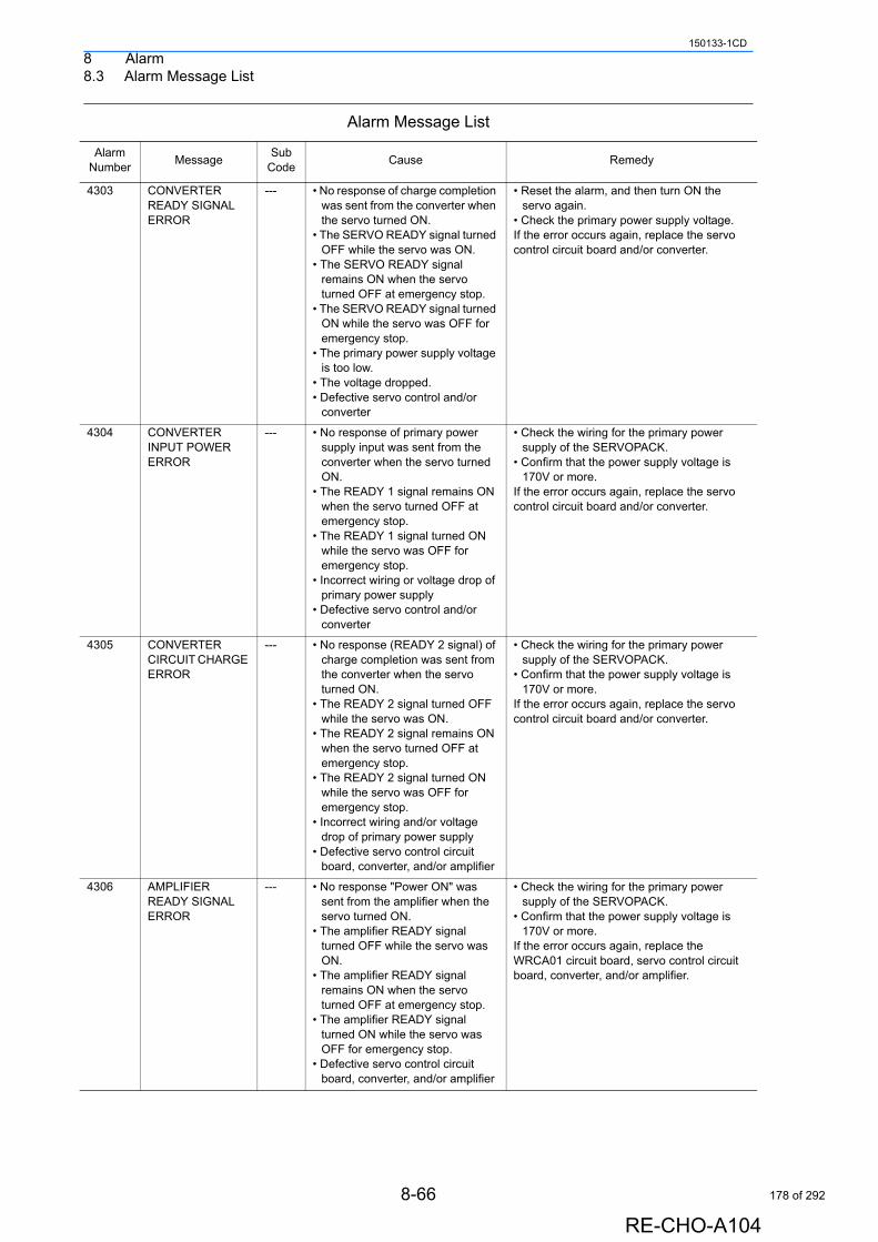
8 Alarm8.3 Alarm Message List
150133-1CD
4303 CONVERTER READY SIGNAL ERROR
--- • No response of charge completion was sent from the converter when the servo turned ON.
• The SERVO READY signal turned OFF while the servo was ON.
• The SERVO READY signal remains ON when the servo turned OFF at emergency stop.
• The SERVO READY signal turned ON while the servo was OFF for emergency stop.
• The primary power supply voltage is too low.
• The voltage dropped.• Defective servo control and/or
converter
• Reset the alarm, and then turn ON the servo again.
• Check the primary power supply voltage. If the error occurs again, replace the servo control circuit board and/or converter.
4304 CONVERTER INPUT POWER ERROR
--- • No response of primary power supply input was sent from the converter when the servo turned ON.
• The READY 1 signal remains ON when the servo turned OFF at emergency stop.
• The READY 1 signal turned ON while the servo was OFF for emergency stop.
• Incorrect wiring or voltage drop of primary power supply
• Defective servo control and/or converter
• Check the wiring for the primary power supply of the SERVOPACK.
• Confirm that the power supply voltage is 170V or more.
If the error occurs again, replace the servo control circuit board and/or converter.
4305 CONVERTER CIRCUIT CHARGE ERROR
--- • No response (READY 2 signal) of charge completion was sent from the converter when the servo turned ON.
• The READY 2 signal turned OFF while the servo was ON.
• The READY 2 signal remains ON when the servo turned OFF at emergency stop.
• The READY 2 signal turned ON while the servo was OFF for emergency stop.
• Incorrect wiring and/or voltage drop of primary power supply
• Defective servo control circuit board, converter, and/or amplifier
• Check the wiring for the primary power supply of the SERVOPACK.
• Confirm that the power supply voltage is 170V or more.
If the error occurs again, replace the servo control circuit board and/or converter.
4306 AMPLIFIER READY SIGNAL ERROR
--- • No response "Power ON" was sent from the amplifier when the servo turned ON.
• The amplifier READY signal turned OFF while the servo was ON.
• The amplifier READY signal remains ON when the servo turned OFF at emergency stop.
• The amplifier READY signal turned ON while the servo was OFF for emergency stop.
• Defective servo control circuit board, converter, and/or amplifier
• Check the wiring for the primary power supply of the SERVOPACK.
• Confirm that the power supply voltage is 170V or more.
If the error occurs again, replace the WRCA01 circuit board, servo control circuit board, converter, and/or amplifier.
Alarm Message List
Alarm Number
MessageSub
CodeCause Remedy
8-66
RE-CHO-A104
178 of 292

8 Alarm8.3 Alarm Message List
150133-1CD
4307 SERVO ON SPEED ERROR
--- The motion speed of the encoder before the dynamic brake turns OFF in servo ON sequence exceeded the threshold for a certain period.• The servo power supply turned
ON while the manipulator (motor and encoder) was moving.
The control power supply cannot be turned ON while the manipulator is moving. Stop the manipulator motion, and then turn ON the servo power supply.
4308 VOLTAGE DROP(CONVERTER)
--- The DC power voltage supplied to the SERVOPACK amplifier dropped below 143V due to:- Low voltage of the primary power supply- Open phase- Defective converter- Defective servo control circuit board
• Check the wiring for the primary power supply of the SERVOPACK.
• Confirm that the power supply voltage is 170V or more.
If the error occurs again, replace the servo control circuit board, servo control circuit board, and/or converter.
4309 DEFECTIVE ENCODER INTERNAL DATA
--- Serial encoder internal parameter error occurred.
• Reset the alarm, and then perform the home positioning again. Turn the power OFF then back ON.
If the error occurs again, replace the motor of the corresponding axis.
4310 ENCODER OVERHEAT
--- The temperature of the encoder exceeded 100 °C. • Encoder thermistor failure
• Review the load condition and ambient operating temperature.
• Confirm that the primary power supply voltage is 200V + 10%.
If the error occurs again, replace the servo control circuit board or the motor.
4311 ENCODER BACK-UP ERROR
--- • Encoder resetting (initialization) not completed
• The position data in the encoder was lost due to the voltage drop of encoder backup battery.
• Reset the alarm, and then perform the home positioning again. Confirm that the encoder backup battery voltage is 2.8V or more.
If the error occurs again, replace the encoder (motor).
4312 ENCODER BATTERY ERROR
--- Encoder backup battery voltage is too low.• The voltage of the encoder
backup battery is below 2.8V. The position data may be lost.
Confirm that the encoder backup battery voltage is 2.8V or more. If not, replace the battery.
4313 SERIAL ENCODER OVER HEAT
--- The temperature of the encoder exceeded 100 °C. • Encoder thermistor failure
• Review the load condition and ambient operating temperature.
• Confirm that the primary power supply voltage is 200V + 10%.
If the error occurs again, replace the servo control circuit board or the motor.
4314 SERIAL ENCODER BATTERY ERROR
--- Encoder backup battery voltage is too low.• The voltage of the encoder
backup battery is below 2.8V. The position data may be lost.
Confirm that the encoder backup battery voltage is 2.8V or more. If not, replace the battery.
4315 COLLISION DETECT
--- • A collision was detected because of the interference between the manipulator and a peripheral device.
• The external force applied to the robot exceeded the threshold.
• Reset the alarm, and then remove the object or move the manipulator back to a safe position.
If the alarm cannot be reset, invalidate the collision detection level setting file or set the detection level higher.
4316 PRESSURE DATA LIMIT
--- The pressure set in the gun pressure file or dry spotting pressure file exceeded the maximum pressure set in the gun condition file.
Reset the pressure value in the gun pressure file or dry spotting pressure file below the maximum pressure value.
Alarm Message List
Alarm Number
MessageSub
CodeCause Remedy
8-67
RE-CHO-A104
179 of 292
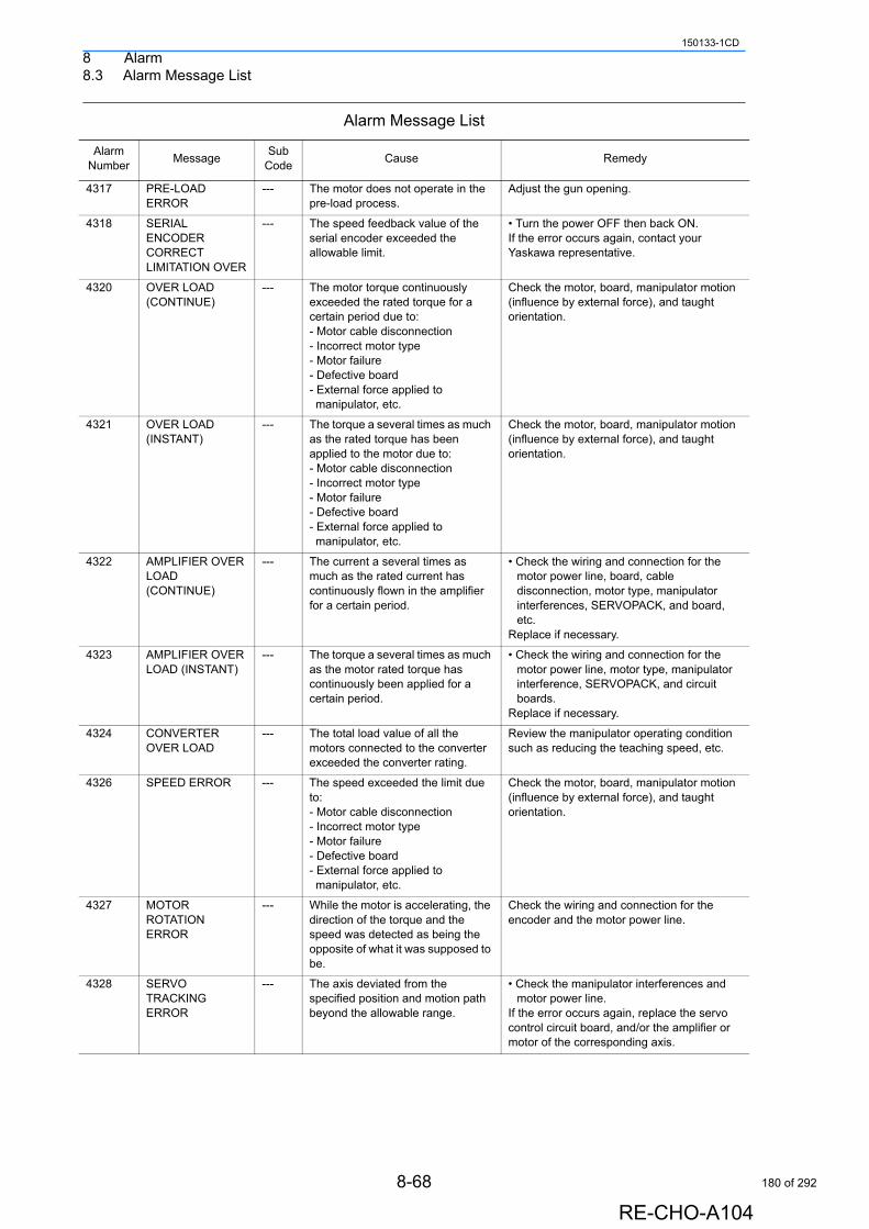
8 Alarm8.3 Alarm Message List
150133-1CD
4317 PRE-LOAD ERROR
--- The motor does not operate in the pre-load process.
Adjust the gun opening.
4318 SERIAL ENCODER CORRECT LIMITATION OVER
--- The speed feedback value of the serial encoder exceeded the allowable limit.
• Turn the power OFF then back ON.If the error occurs again, contact your Yaskawa representative.
4320 OVER LOAD (CONTINUE)
--- The motor torque continuously exceeded the rated torque for a certain period due to:- Motor cable disconnection- Incorrect motor type- Motor failure- Defective board- External force applied to manipulator, etc.
Check the motor, board, manipulator motion (influence by external force), and taught orientation.
4321 OVER LOAD (INSTANT)
--- The torque a several times as much as the rated torque has been applied to the motor due to:- Motor cable disconnection- Incorrect motor type- Motor failure- Defective board- External force applied to manipulator, etc.
Check the motor, board, manipulator motion (influence by external force), and taught orientation.
4322 AMPLIFIER OVER LOAD (CONTINUE)
--- The current a several times as much as the rated current has continuously flown in the amplifier for a certain period.
• Check the wiring and connection for the motor power line, board, cable disconnection, motor type, manipulator interferences, SERVOPACK, and board, etc.
Replace if necessary.
4323 AMPLIFIER OVER LOAD (INSTANT)
--- The torque a several times as much as the motor rated torque has continuously been applied for a certain period.
• Check the wiring and connection for the motor power line, motor type, manipulator interference, SERVOPACK, and circuit boards.
Replace if necessary.
4324 CONVERTER OVER LOAD
--- The total load value of all the motors connected to the converter exceeded the converter rating.
Review the manipulator operating condition such as reducing the teaching speed, etc.
4326 SPEED ERROR --- The speed exceeded the limit due to:- Motor cable disconnection- Incorrect motor type- Motor failure- Defective board- External force applied to manipulator, etc.
Check the motor, board, manipulator motion (influence by external force), and taught orientation.
4327 MOTOR ROTATION ERROR
--- While the motor is accelerating, the direction of the torque and the speed was detected as being the opposite of what it was supposed to be.
Check the wiring and connection for the encoder and the motor power line.
4328 SERVO TRACKING ERROR
--- The axis deviated from the specified position and motion path beyond the allowable range.
• Check the manipulator interferences and motor power line.
If the error occurs again, replace the servo control circuit board, and/or the amplifier or motor of the corresponding axis.
Alarm Message List
Alarm Number
MessageSub
CodeCause Remedy
8-68
RE-CHO-A104
180 of 292
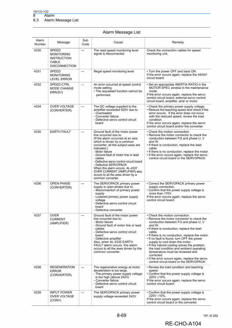
8 Alarm8.3 Alarm Message List
150133-1CD
4330 SPEED MONITORING INSTRUCTION CABLE DISCONNECTION
--- The read speed monitoring level signal is disconnected.
Check the connection cables for speed monitoring unit.
4331 SPEED MONITORING LEVEL ERROR
--- Illegal speed monitoring level • Turn the power OFF and back ON.If the error occurs again, replace the AXA01 circuit board.
4332 SPEED CTRL MODE CHANGE ERR(SV)
--- An error occurred at speed control mode setting.• The requested function cannot be
performed.
• Set an appropriate INERTIA RATIO in the MOTOR SPEC window in the maintenance mode.
If the error occurs again, replace the servo control circuit board, external servo control circuit board, amplifier, and/ or motor.
4334 OVER VOLTAGE (CONVERTER)
--- The DC voltage supplied to the amplifier exceeded 420V due to:- Overloaded- Converter failure- Defective servo control circuit board
• Check the primary power supply voltage.• Reduce the teaching speed and check if the
error occurs. If the error does not occur with the reduced speed, review the load condition.
If the error occurs again, replace the servo control circuit board and/or the converter.
4335 EARTH FAULT --- Ground fault of the motor power line occurred due to:(If the alarm occurred at an axis which is driven by a common converter, all the subject axes are indicated.)- Motor failure- Ground fault of motor line or lead cables
- Defective servo control circuit board - Defective SERVOPACKWhen this alarm occurs, AL-4337 OVER CURRENT (AMPLIFIER) also occurs to all the axes driven by a common converter.
• Check the motion connection.• Remove the motor connector to check the
conduction between FG and phase U, V and W.
• If there is conduction, replace the lead cable.
• If there is no conduction, replace the motor.• If the error occurs again, replace the servo
control circuit board or the SERVOPACK.
4336 OPEN PHASE (CONVERTER)
--- The SERVOPACK primary power supply is open-phase due to:- Misconnection of primary power supply
- Lowered primary power supply voltage
- Defective servo control circuit board
- Defective converter
• Correct the SERVOPACK primary power supply connection,
• Confirm that the power supply voltage is more than 170V.
If the error occurs again, replace the servo control circuit board.
4337 OVER CURRENT (AMPLIFIER)
--- Ground fault of the motor power line occurred due to:- Motor failure- Ground fault of motor line or lead cables
- Defective servo control circuit board
- Defective amplifier Also, when AL-4335 EARTH FAULT alarm occurs, this alarm occurs to all the axes driven by the common converter.
• Check the motion connection.• Remove the motor connector to check the
conduction between FG and phase U, V and W.
• If there is conduction, replace the lead cable.
• If there is no conduction, replace the motor.• If no fault is found, turn OFF the power
supply to cool down the motor. • If this natural cooling solves the problem,
the load condition and ambient operating temperature must be reviewed and corrected.
• If the error occurs again, replace the servo control circuit board or the SERVOPACK.
4338 REGENERATION ERROR (CONVERTER)
--- The regenerative energy at motor deceleration is too large.- The primary power supply voltage is too high (above 242V)
- Converter failure- Defective servo control circuit board
• Review the load condition and teaching speed.
• Confirm that the power supply voltage is 220V ±10%.
If the error occurs again, replace the servo control circuit board.
4339 INPUT POWER OVER VOLTAGE (CONV)
--- The SERVOPACK primary power supply voltage exceeded 242V.
• Confirm that the power supply voltage is 220V ±10%.
If the error occurs again, replace the servo control circuit board or the converter.
Alarm Message List
Alarm Number
MessageSub
CodeCause Remedy
8-69
RE-CHO-A104
181 of 292
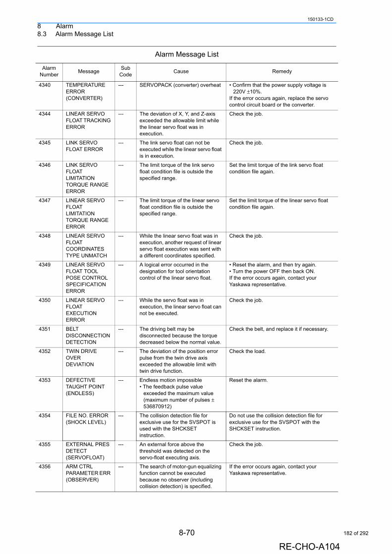
8 Alarm8.3 Alarm Message List
150133-1CD
4340 TEMPERATURE ERROR (CONVERTER)
--- SERVOPACK (converter) overheat • Confirm that the power supply voltage is 220V ±10%.
If the error occurs again, replace the servo control circuit board or the converter.
4344 LINEAR SERVO FLOAT TRACKING ERROR
--- The deviation of X, Y, and Z-axis exceeded the allowable limit while the linear servo float was in execution.
Check the job.
4345 LINK SERVO FLOAT ERROR
--- The link servo float can not be executed while the linear servo float is in execution.
Check the job.
4346 LINK SERVO FLOAT LIMITATION TORQUE RANGE ERROR
--- The limit torque of the link servo float condition file is outside the specified range.
Set the limit torque of the link servo float condition file again.
4347 LINEAR SERVO FLOAT LIMITATION TORQUE RANGE ERROR
--- The limit torque of the linear servo float condition file is outside the specified range.
Set the limit torque of the linear servo float condition file again.
4348 LINEAR SERVO FLOAT COORDINATES TYPE UNMATCH
--- While the linear servo float was in execution, another request of linear servo float execution was sent with a different coordinates specified.
Check the job.
4349 LINEAR SERVO FLOAT TOOL POSE CONTROL SPECIFICATION ERROR
--- A logical error occurred in the designation for tool orientation control of the linear servo float.
• Reset the alarm, and then try again. • Turn the power OFF then back ON. If the error occurs again, contact your Yaskawa representative.
4350 LINEAR SERVO FLOAT EXECUTION ERROR
--- While the servo float was in execution, the linear servo float can not be executed.
Check the job.
4351 BELT DISCONNECTION DETECTION
--- The driving belt may be disconnected because the torque decreased below the normal value.
Check the belt, and replace it if necessary.
4352 TWIN DRIVE OVER DEVIATION
--- The deviation of the position error pulse from the twin drive axis exceeded the allowable limit with twin drive function.
Check the load.
4353 DEFECTIVE TAUGHT POINT (ENDLESS)
--- Endless motion impossible • The feedback pulse value
exceeded the maximum value (maximum number of pulses ± 536870912)
Reset the alarm.
4354 FILE NO. ERROR (SHOCK LEVEL)
--- The collision detection file for exclusive use for the SVSPOT is used with the SHCKSET instruction.
Do not use the collision detection file for exclusive use for the SVSPOT with the SHCKSET instruction.
4355 EXTERNAL PRES DETECT (SERVOFLOAT)
--- An external force above the threshold was detected on the servo-float executing axis.
Check the job.
4356 ARM CTRL PARAMETER ERR (OBSERVER)
--- The search of motor-gun equalizing function cannot be executed because no observer (including collision detection) is specified.
If the error occurs again, contact your Yaskawa representative.
Alarm Message List
Alarm Number
MessageSub
CodeCause Remedy
8-70
RE-CHO-A104
182 of 292
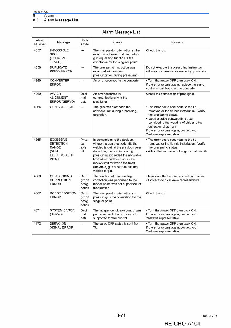
8 Alarm8.3 Alarm Message List
150133-1CD
4357 IMPOSSIBLE SRCH (EQUALIZE TEACH)
--- The manipulator orientation at the execution of search of the motor-gun equalizing function is the orientation for the singular point.
Check the job.
4358 DUPLICATE PRESS ERROR
--- The pressuring instruction was executed with manual pressurization during pressuring.
Do not execute the pressuring instruction with manual pressurization during pressuring.
4359 CONVERTER ERROR
--- An error occurred in the converter. • Turn the power OFF then back ON. If the error occurs again, replace the servo control circuit board or the converter.
4360 WAFER ALIGNMENT ERROR (SERVO)
Decimal data
An error occurred in communications with the prealigner.
Check the connection of prealigner.
4364 GUN SOFT LIMIT --- The gun axis exceeded the software limit during pressuring operation.
• The error could occur due to the tip removed or the tip mis-installation. Verify the pressuring status.
• Set the pulse software limit again considering the wearing of chip and the deflection of gun arm.
If the error occurs again, contact your Yaskawa representative.
4365 EXCESSIVE DETECTION RANGE(GUN ELECTRODE HIT POINT)
Physical axis bit
In comparison to the position, where the gun electrode hits the welded target, at the previous wear detection, the position during pressuring exceeded the allowable limit which had been set in the motion limit for which the fixed (movable) gun electrode hits the welded target.
• The error could occur due to the tip removed or the tip mis-installation. Verify the pressuring status.
• Adjust the set value of the gun condition file.
4366 GUN BENDING CORRECTION ERROR
Cntrl grp bit designation
The function of gun bending correction was performed to the model which was not supported for the function.
• Invalidate the bending correction function.• Contact your Yaskawa representative.
4367 ROBOT POSITION ERROR
Cntrl grp bit designation
The manipulator orientation at pressuring is the orientation for the singular point.
Check the job.
4371 SYSTEM ERROR(SERVO)
Decimal data
The independent brake control was performed in TU which was not supported for the control.
• Turn the power OFF then back ON. If the error occurs again, contact your Yaskawa representative.
4372 SERVO ON SIGNAL ERROR
--- The servo OFF status is sent from TU.
• Turn the power OFF then back ON. If the error occurs again, contact your Yaskawa representative.
Alarm Message List
Alarm Number
MessageSub
CodeCause Remedy
8-71
RE-CHO-A104
183 of 292

8 Alarm8.3 Alarm Message List
150133-1CD
4400NOT READY (ARITH)
The arithmetic process for motion control did not complete within regulated time.
1 • No motion command was prepared.
• Reset the alarm, and then try again. • Turn the power OFF then back ON. If the error occurs again, contact your Yaskawa representative.
2 • The arithmetic processing section is not ready for JOG operation.
3 • The arithmetic processing section is not ready for the playback operation.
4 • The prereading processing in the arithmetic processing section has not completed.
5 • The arithmetic processing section is not ready for the timer follow-up of the conveyor tracking function.
6 • The prereading processing in the arithmetic processing section has not completed when specifying the target position.
4401SEQUENCE TASK CONTROL ERROR
An error occurred in job execution process. • Reset the alarm, and then try again.• Turn the power OFF then back ON.If the error occurs again, contact your Yaskawa representative.
1 • Unused A_BANK does not exist in the prereading processing of move instruction.
2 • Unused bank priority does not exist in the prereading processing of move instruction.
5 • A_BANK pointer is not set.
6 • A_BANK conversion could not be performed.
7 • The specified A_BANK number does not exist.
20 • An error occurred when system number (MSS) was obtained.
21 • An error occurred in RMS960 system call.
22 • Undefined interrupt command was received.
23 • Job start condition is not defined.
24 • An error occurred in instruction prefetch queue operation.
Alarm Message List
Alarm Number
MessageSub
CodeCause Remedy
8-72
RE-CHO-A104
184 of 292
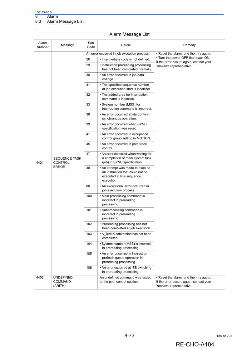
8 Alarm8.3 Alarm Message List
150133-1CD
4401SEQUENCE TASK CONTROL ERROR
An error occurred in job execution process. • Reset the alarm, and then try again.• Turn the power OFF then back ON.If the error occurs again, contact your Yaskawa representative.
26 • Intermediate code is not defined.
29 • Instruction prereading processing has not been completed normally.
30 • An error occurred in job data change.
31 • The specified sequence number at job execution start is incorrect.
32 • The added area for interruption command is incorrect.
33 • System number (MSS) for interruption command is incorrect.
38 • An error occurred at start of twin synchronous operation.
39 • An error occurred when SYNC specification was reset.
41 • An error occurred in occupation control group setting in MOTION.
45 • An error occurred in path/trace control.
47 • An error occurred when waiting for a completion of main system task (job) in SYNC specification.
48 • An attempt was made to execute an instruction that could not be executed at line sequence execution.
80 • An exceptional error occurred in job execution process.
100 • Main processing command is incorrect in prereading processing.
101 • Subprocessing command is incorrect in prereading processing.
102 • Prereading processing has not been completed at job execution.
103 • A_BANK conversion has not been completed.
104 • System number (MSS) is incorrect in prereading processing.
105 • An error occurred in instruction prefetch queue operation in prereading processing.
106 • An error occurred at IES switching in prereading processing.
4402 UNDEFINED COMMAND (ARITH)
An undefined command was issued to the path control section.
• Reset the alarm, and then try again.If the error occurs again, contact your Yaskawa representative.
Alarm Message List
Alarm Number
MessageSub
CodeCause Remedy
8-73
RE-CHO-A104
185 of 292
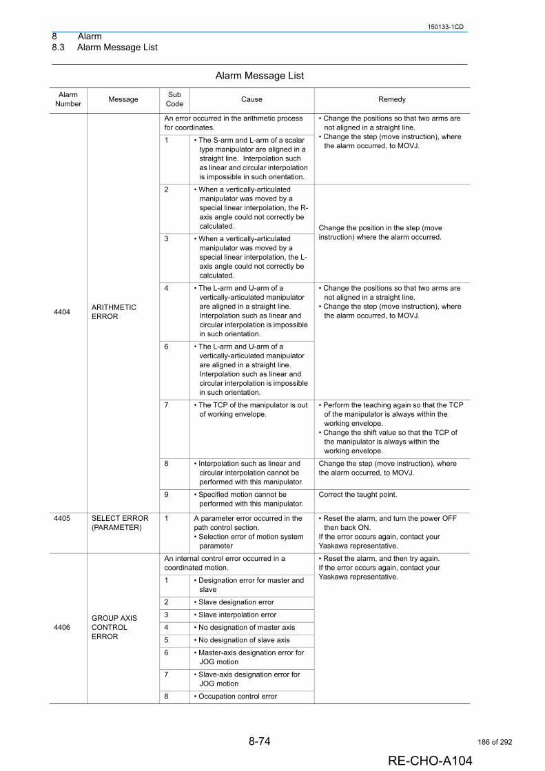
8 Alarm8.3 Alarm Message List
150133-1CD
4404ARITHMETIC ERROR
An error occurred in the arithmetic process for coordinates.
• Change the positions so that two arms are not aligned in a straight line.
• Change the step (move instruction), where the alarm occurred, to MOVJ.
1 • The S-arm and L-arm of a scalar type manipulator are aligned in a straight line. Interpolation such as linear and circular interpolation is impossible in such orientation.
2 • When a vertically-articulated manipulator was moved by a special linear interpolation, the R-axis angle could not correctly be calculated. Change the position in the step (move
instruction) where the alarm occurred.3 • When a vertically-articulated manipulator was moved by a special linear interpolation, the L-axis angle could not correctly be calculated.
4 • The L-arm and U-arm of a vertically-articulated manipulator are aligned in a straight line. Interpolation such as linear and circular interpolation is impossible in such orientation.
• Change the positions so that two arms are not aligned in a straight line.
• Change the step (move instruction), where the alarm occurred, to MOVJ.
6 • The L-arm and U-arm of a vertically-articulated manipulator are aligned in a straight line. Interpolation such as linear and circular interpolation is impossible in such orientation.
7 • The TCP of the manipulator is out of working envelope.
• Perform the teaching again so that the TCP of the manipulator is always within the working envelope.
• Change the shift value so that the TCP of the manipulator is always within the working envelope.
8 • Interpolation such as linear and circular interpolation cannot be performed with this manipulator.
Change the step (move instruction), where the alarm occurred, to MOVJ.
9 • Specified motion cannot be performed with this manipulator.
Correct the taught point.
4405 SELECT ERROR (PARAMETER)
1 A parameter error occurred in the path control section.• Selection error of motion system
parameter
• Reset the alarm, and turn the power OFF then back ON.
If the error occurs again, contact your Yaskawa representative.
4406GROUP AXIS CONTROL ERROR
An internal control error occurred in a coordinated motion.
• Reset the alarm, and then try again. If the error occurs again, contact your Yaskawa representative.1 • Designation error for master and
slave
2 • Slave designation error
3 • Slave interpolation error
4 • No designation of master axis
5 • No designation of slave axis
6 • Master-axis designation error for JOG motion
7 • Slave-axis designation error for JOG motion
8 • Occupation control error
Alarm Message List
Alarm Number
MessageSub
CodeCause Remedy
8-74
RE-CHO-A104
186 of 292
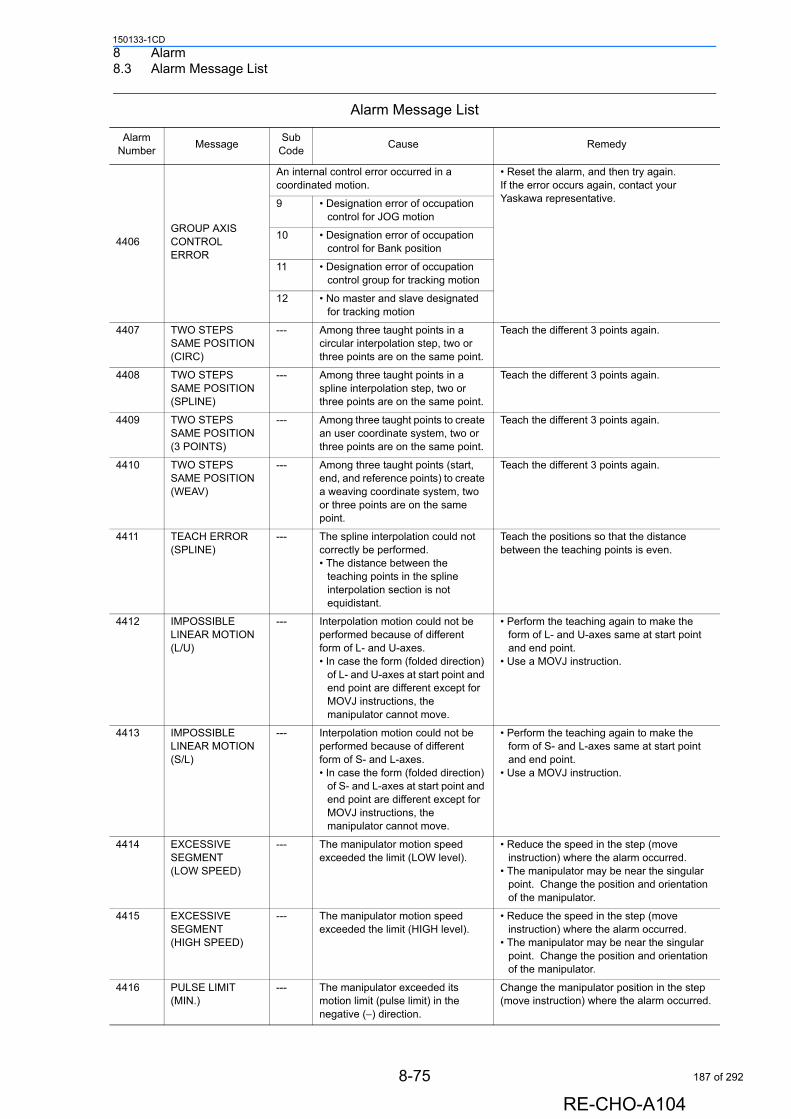
8 Alarm8.3 Alarm Message List
150133-1CD
4406GROUP AXIS CONTROL ERROR
An internal control error occurred in a coordinated motion.
• Reset the alarm, and then try again. If the error occurs again, contact your Yaskawa representative.9 • Designation error of occupation
control for JOG motion
10 • Designation error of occupation control for Bank position
11 • Designation error of occupation control group for tracking motion
12 • No master and slave designated for tracking motion
4407 TWO STEPS SAME POSITION (CIRC)
--- Among three taught points in a circular interpolation step, two or three points are on the same point.
Teach the different 3 points again.
4408 TWO STEPS SAME POSITION (SPLINE)
--- Among three taught points in a spline interpolation step, two or three points are on the same point.
Teach the different 3 points again.
4409 TWO STEPS SAME POSITION (3 POINTS)
--- Among three taught points to create an user coordinate system, two or three points are on the same point.
Teach the different 3 points again.
4410 TWO STEPS SAME POSITION (WEAV)
--- Among three taught points (start, end, and reference points) to create a weaving coordinate system, two or three points are on the same point.
Teach the different 3 points again.
4411 TEACH ERROR (SPLINE)
--- The spline interpolation could not correctly be performed.• The distance between the
teaching points in the spline interpolation section is not equidistant.
Teach the positions so that the distance between the teaching points is even.
4412 IMPOSSIBLE LINEAR MOTION (L/U)
--- Interpolation motion could not be performed because of different form of L- and U-axes.• In case the form (folded direction)
of L- and U-axes at start point and end point are different except for MOVJ instructions, the manipulator cannot move.
• Perform the teaching again to make the form of L- and U-axes same at start point and end point.
• Use a MOVJ instruction.
4413 IMPOSSIBLE LINEAR MOTION (S/L)
--- Interpolation motion could not be performed because of different form of S- and L-axes.• In case the form (folded direction)
of S- and L-axes at start point and end point are different except for MOVJ instructions, the manipulator cannot move.
• Perform the teaching again to make the form of S- and L-axes same at start point and end point.
• Use a MOVJ instruction.
4414 EXCESSIVE SEGMENT (LOW SPEED)
--- The manipulator motion speed exceeded the limit (LOW level).
• Reduce the speed in the step (move instruction) where the alarm occurred.
• The manipulator may be near the singular point. Change the position and orientation of the manipulator.
4415 EXCESSIVE SEGMENT (HIGH SPEED)
--- The manipulator motion speed exceeded the limit (HIGH level).
• Reduce the speed in the step (move instruction) where the alarm occurred.
• The manipulator may be near the singular point. Change the position and orientation of the manipulator.
4416 PULSE LIMIT (MIN.)
--- The manipulator exceeded its motion limit (pulse limit) in the negative (−) direction.
Change the manipulator position in the step (move instruction) where the alarm occurred.
Alarm Message List
Alarm Number
MessageSub
CodeCause Remedy
8-75
RE-CHO-A104
187 of 292
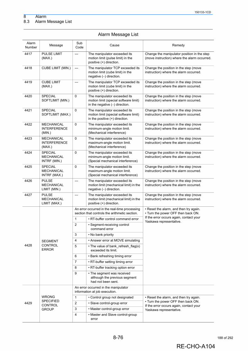
8 Alarm8.3 Alarm Message List
150133-1CD
4417 PULSE LIMIT (MAX.)
--- The manipulator exceeded its motion limit (pulse limit) in the positive (+) direction.
Change the manipulator position in the step (move instruction) where the alarm occurred.
4418 CUBE LIMIT (MIN.) --- The manipulator TCP exceeded its motion limit (cube limit) in the negative (−) direction.
Change the position in the step (move instruction) where the alarm occurred.
4419 CUBE LIMIT (MAX.)
--- The manipulator TCP exceeded its motion limit (cube limit) in the positive (+) direction.
Change the position in the step (move instruction) where the alarm occurred.
4420 SPECIAL SOFTLIMIT (MIN.)
0 The manipulator exceeded its motion limit (special software limit) in the negative (−) direction.
Change the position in the step (move instruction) where the alarm occurred.
4421 SPECIAL SOFTLIMIT (MAX.)
0 The manipulator exceeded its motion limit (special software limit) in the positive (+) direction.
Change the position in the step (move instruction) where the alarm occurred.
4422 MECHANICAL INTERFERENCE (MIN.)
0 The manipulator exceeded its minimum-angle motion limit. (Mechanical interference)
Change the position in the step (move instruction) where the alarm occurred.
4423 MECHANICAL INTERFERENCE (MAX.)
0 The manipulator exceeded its maximum-angle motion limit. (Mechanical interference)
Change the position in the step (move instruction) where the alarm occurred.
4424 SPECIAL MECHANICAL INTRF (MIN.)
0 The manipulator exceeded its minimum-angle motion limit. (Special mechanical interference)
Change the position in the step (move instruction) where the alarm occurred.
4425 SPECIAL MECHANICAL INTRF (MAX.)
0 The manipulator exceeded its maximum-angle motion limit. (Special mechanical interference)
Change the position in the step (move instruction) where the alarm occurred.
4426 PULSE MECHANICAL LIMIT (MIN.)
--- The manipulator exceeded its motion limit (mechanical limit) in the negative (−) direction.
Change the position in the step (move instruction) where the alarm occurred.
4427 PULSE MECHANICAL LIMIT (MAX.)
--- The manipulator exceeded its motion limit (mechanical limit) in the positive (+) direction.
Change the position in the step (move instruction) where the alarm occurred.
4428SEGMENT CONTROL ERROR
An error occurred in the real-time processing section that controls the arithmetic section.
• Reset the alarm, and then try again. • Turn the power OFF then back ON. If the error occurs again, contact your Yaskawa representative.
1 • RT-buffer control command error
2 • Segment-receiving control command error
3 • No bank priority
4 • Answer error at MOVE simulating
5 • The value of bank_refresh_flag(x) exceeded its limit.
6 • Bank refreshing timing error
7 • RT-buffer setting timing error
8 • RT-buffer tracking option error
9 • The segment was received although the previous segment had not been sent.
4429
WRONG SPECIFIED CONTROL GROUP
An error occurred in the manipulator information at job execution.
1 • Control group not designated • Reset the alarm, and then try again. • Turn the power OFF then back ON. If the error occurs again, contact your Yaskawa representative.
2 • Slave control-group error
3 • Master control-group error
4 • Master and Slave control-group error
Alarm Message List
Alarm Number
MessageSub
CodeCause Remedy
8-76
RE-CHO-A104
188 of 292
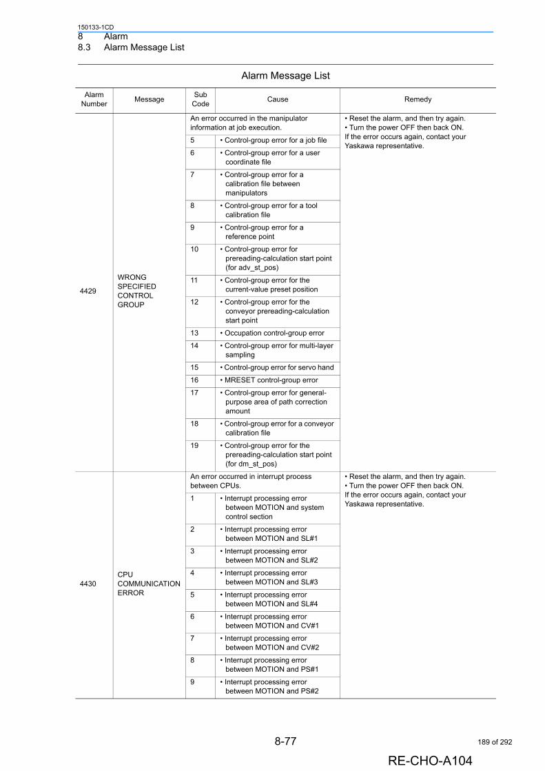
8 Alarm8.3 Alarm Message List
150133-1CD
4429
WRONG SPECIFIED CONTROL GROUP
An error occurred in the manipulator information at job execution.
• Reset the alarm, and then try again. • Turn the power OFF then back ON. If the error occurs again, contact your Yaskawa representative.
5 • Control-group error for a job file
6 • Control-group error for a user coordinate file
7 • Control-group error for a calibration file between manipulators
8 • Control-group error for a tool calibration file
9 • Control-group error for a reference point
10 • Control-group error for prereading-calculation start point (for adv_st_pos)
11 • Control-group error for the current-value preset position
12 • Control-group error for the conveyor prereading-calculation start point
13 • Occupation control-group error
14 • Control-group error for multi-layer sampling
15 • Control-group error for servo hand
16 • MRESET control-group error
17 • Control-group error for general-purpose area of path correction amount
18 • Control-group error for a conveyor calibration file
19 • Control-group error for the prereading-calculation start point (for dm_st_pos)
4430CPU COMMUNICATION ERROR
An error occurred in interrupt process between CPUs.
• Reset the alarm, and then try again. • Turn the power OFF then back ON. If the error occurs again, contact your Yaskawa representative.
1 • Interrupt processing error between MOTION and system control section
2 • Interrupt processing error between MOTION and SL#1
3 • Interrupt processing error between MOTION and SL#2
4 • Interrupt processing error between MOTION and SL#3
5 • Interrupt processing error between MOTION and SL#4
6 • Interrupt processing error between MOTION and CV#1
7 • Interrupt processing error between MOTION and CV#2
8 • Interrupt processing error between MOTION and PS#1
9 • Interrupt processing error between MOTION and PS#2
Alarm Message List
Alarm Number
MessageSub
CodeCause Remedy
8-77
RE-CHO-A104
189 of 292
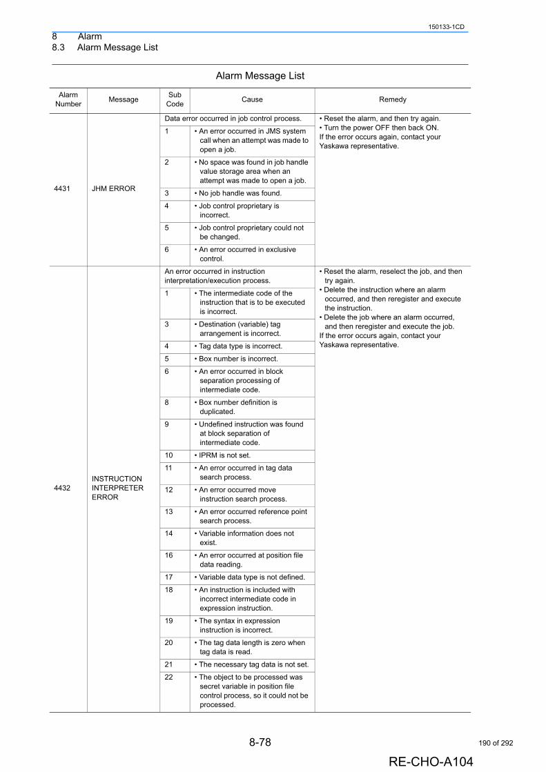
8 Alarm8.3 Alarm Message List
150133-1CD
4431 JHM ERROR
Data error occurred in job control process. • Reset the alarm, and then try again.• Turn the power OFF then back ON.If the error occurs again, contact your Yaskawa representative.
1 • An error occurred in JMS system call when an attempt was made to open a job.
2 • No space was found in job handle value storage area when an attempt was made to open a job.
3 • No job handle was found.
4 • Job control proprietary is incorrect.
5 • Job control proprietary could not be changed.
6 • An error occurred in exclusive control.
4432INSTRUCTION INTERPRETER ERROR
An error occurred in instruction interpretation/execution process.
• Reset the alarm, reselect the job, and then try again.
• Delete the instruction where an alarm occurred, and then reregister and execute the instruction.
• Delete the job where an alarm occurred, and then reregister and execute the job.
If the error occurs again, contact your Yaskawa representative.
1 • The intermediate code of the instruction that is to be executed is incorrect.
3 • Destination (variable) tag arrangement is incorrect.
4 • Tag data type is incorrect.
5 • Box number is incorrect.
6 • An error occurred in block separation processing of intermediate code.
8 • Box number definition is duplicated.
9 • Undefined instruction was found at block separation of intermediate code.
10 • IPRM is not set.
11 • An error occurred in tag data search process.
12 • An error occurred move instruction search process.
13 • An error occurred reference point search process.
14 • Variable information does not exist.
16 • An error occurred at position file data reading.
17 • Variable data type is not defined.
18 • An instruction is included with incorrect intermediate code in expression instruction.
19 • The syntax in expression instruction is incorrect.
20 • The tag data length is zero when tag data is read.
21 • The necessary tag data is not set.
22 • The object to be processed was secret variable in position file control process, so it could not be processed.
Alarm Message List
Alarm Number
MessageSub
CodeCause Remedy
8-78
RE-CHO-A104
190 of 292
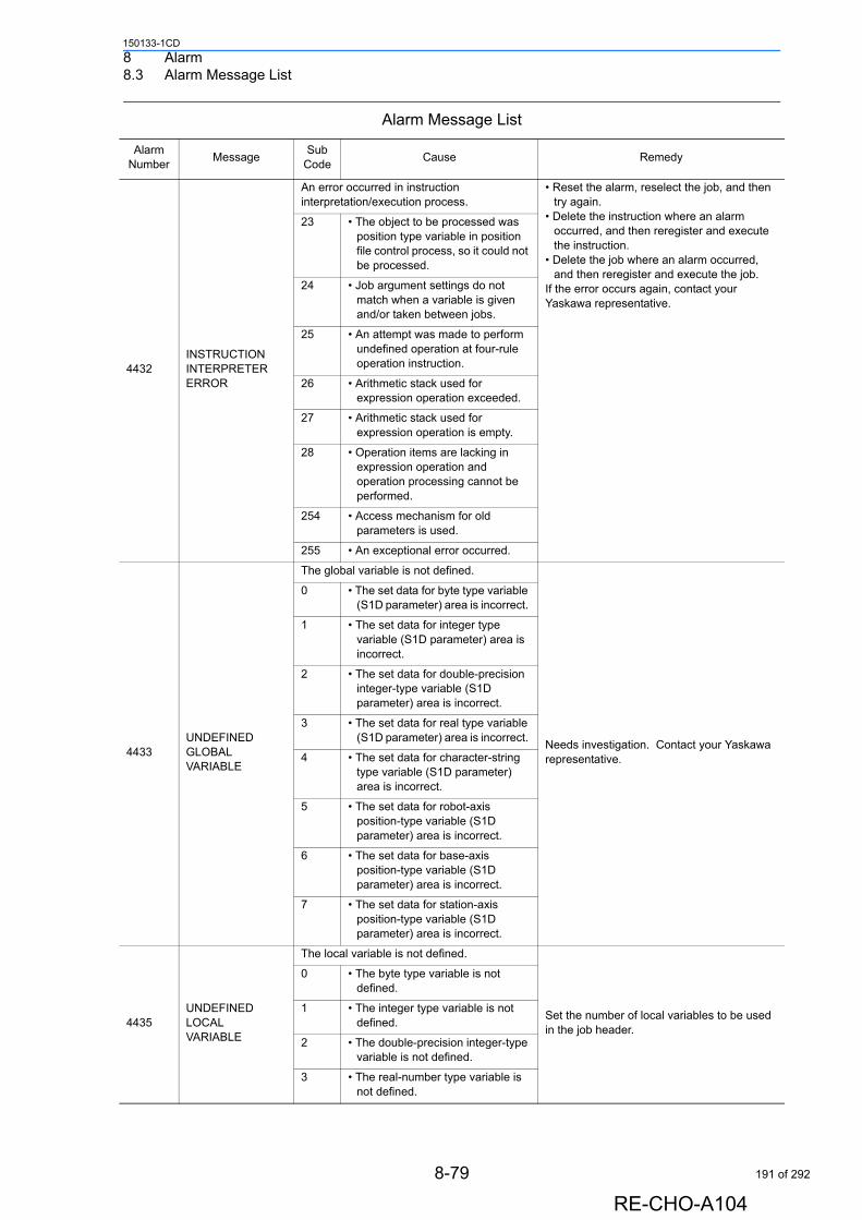
8 Alarm8.3 Alarm Message List
150133-1CD
4432INSTRUCTION INTERPRETER ERROR
An error occurred in instruction interpretation/execution process.
• Reset the alarm, reselect the job, and then try again.
• Delete the instruction where an alarm occurred, and then reregister and execute the instruction.
• Delete the job where an alarm occurred, and then reregister and execute the job.
If the error occurs again, contact your Yaskawa representative.
23 • The object to be processed was position type variable in position file control process, so it could not be processed.
24 • Job argument settings do not match when a variable is given and/or taken between jobs.
25 • An attempt was made to perform undefined operation at four-rule operation instruction.
26 • Arithmetic stack used for expression operation exceeded.
27 • Arithmetic stack used for expression operation is empty.
28 • Operation items are lacking in expression operation and operation processing cannot be performed.
254 • Access mechanism for old parameters is used.
255 • An exceptional error occurred.
4433UNDEFINED GLOBAL VARIABLE
The global variable is not defined.
Needs investigation. Contact your Yaskawa representative.
0 • The set data for byte type variable (S1D parameter) area is incorrect.
1 • The set data for integer type variable (S1D parameter) area is incorrect.
2 • The set data for double-precision integer-type variable (S1D parameter) area is incorrect.
3 • The set data for real type variable (S1D parameter) area is incorrect.
4 • The set data for character-string type variable (S1D parameter) area is incorrect.
5 • The set data for robot-axis position-type variable (S1D parameter) area is incorrect.
6 • The set data for base-axis position-type variable (S1D parameter) area is incorrect.
7 • The set data for station-axis position-type variable (S1D parameter) area is incorrect.
4435UNDEFINED LOCAL VARIABLE
The local variable is not defined.
Set the number of local variables to be used in the job header.
0 • The byte type variable is not defined.
1 • The integer type variable is not defined.
2 • The double-precision integer-type variable is not defined.
3 • The real-number type variable is not defined.
Alarm Message List
Alarm Number
MessageSub
CodeCause Remedy
8-79
RE-CHO-A104
191 of 292

8 Alarm8.3 Alarm Message List
150133-1CD
4435UNDEFINED LOCAL VARIABLE
The local variable is not defined.
Set the number of local variables to be used in the job header.
4 • The character-string type variable is not defined.
5 • The robot-axis position-type variable is not defined.
6 • The base-axis position-type variable is not defined.
7 • The station-axis position-type variable is not defined.
4436 LESS THAN 3 STEP (CIRCULAR)
--- An error occurred in circular interpolation instruction execution.• There is no continuous three
points or more for circular interpolation step.
Reset the alarm, and then perform teaching so that circulation interpolation steps are continuous three points or more.
4437 LESS THAN 3 STEP (SPLINE)
--- An error occurred in spline interpolation instruction execution.• There is no continuous three
points or more for spline interpolation step.
Reset the alarm, and then perform teaching so that spline interpolation steps are continuous three points or more.
4438 UNDEFINED JOB --- The job to be executed is not registered in the memory.
• Reset the alarm, and then register the job.• Delete the CALL/JUMP instruction where
an alarm occurred.
4439 UNDEFINED LAVEL
--- An error occurred in label jump execution.• The label for jump destination
does not exist in the job.
• Reset the alarm, and then register the label.• Delete the JUMP instruction where an alarm
occurred.
4440 UNDEFINED RETURN JOB
--- Call source job does not exist in the job call stack.
• Reset the alarm, and then execute the master (start) job.
• Delete the RET instruction.
4441 LACK OF LOCAL VARIABLE AREA
--- An error occurred when memory area for local variable was obtained. • Memory area is lacking because
too many local variables in the job are used.
Reset the alarm, and then reduce the number of local variables to be used.
4444 UNSUCCESSFUL FINE POSITIONING
--- When PL = 0 or an external servo turned OFF, the number of the servo error pulses did not fall in the limit range that had been set in a parameter, within the specified time.
• Reset the alarm, and then check if external force is applied to the manipulator. If external force is applied to the manipulator, move the manipulator by the axis operation, etc. to remove the external force. Then, try again.
• If the error occurs again although no external force is applied to the manipulator, re-insert the system CPU board correctly.
If the error occurs again, contact your Yaskawa representative.
4445DATA PRESET ERROR
Data error occurred at job prereading reinterpretation.
• Reset the alarm, reselect the job, and then try again.
If the error occurs again, contact your Yaskawa representative.1 • The token for prereading
processing could not be obtained.
2 • The prereading processing has not been completed within the time, and the waiting time for completion exceeded the limit.
3 • The prereading operation processing has not been completed within the time, and the waiting time for completion exceeded the limit.
Alarm Message List
Alarm Number
MessageSub
CodeCause Remedy
8-80
RE-CHO-A104
192 of 292
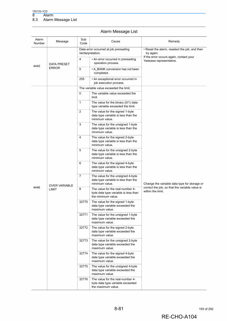
8 Alarm8.3 Alarm Message List
150133-1CD
4445DATA PRESET ERROR
Data error occurred at job prereading reinterpretation.
• Reset the alarm, reselect the job, and then try again.
If the error occurs again, contact your Yaskawa representative.4 • An error occurred in prereading
operation process.
5 • A_BANK conversion has not been completed.
255 • An exceptional error occurred in job execution process.
4446OVER VARIABLE LIMIT
The variable value exceeded the limit.
Change the variable data type for storage or correct the job, so that the variable value is within the limit.
0 The variable value exceeded the limit.
1 The value for the binary (0/1) data type variable exceeded the limit.
2 The value for the signed 1-byte data type variable is less than the minimum value.
3 The value for the unsigned 1-byte data type variable is less than the minimum value.
4 The value for the signed 2-byte data type variable is less than the minimum value.
5 The value for the unsigned 2-byte data type variable is less than the minimum value.
6 The value for the signed 4-byte data type variable is less than the minimum value.
7 The value for the unsigned 4-byte data type variable is less than the minimum value.
8 The value for the real-number 4-byte data type variable is less than the minimum value.
32770 The value for the signed 1-byte data type variable exceeded the maximum value.
32771 The value for the unsigned 1-byte data type variable exceeded the maximum value.
32772 The value for the signed 2-byte data type variable exceeded the maximum value.
32773 The value for the unsigned 2-byte data type variable exceeded the maximum value.
32774 The value for the signed 4-byte data type variable exceeded the maximum value.
32775 The value for the unsigned 4-byte data type variable exceeded the maximum value.
32776 The value for the real-number 4-byte data type variable exceeded the maximum value.
Alarm Message List
Alarm Number
MessageSub
CodeCause Remedy
8-81
RE-CHO-A104
193 of 292
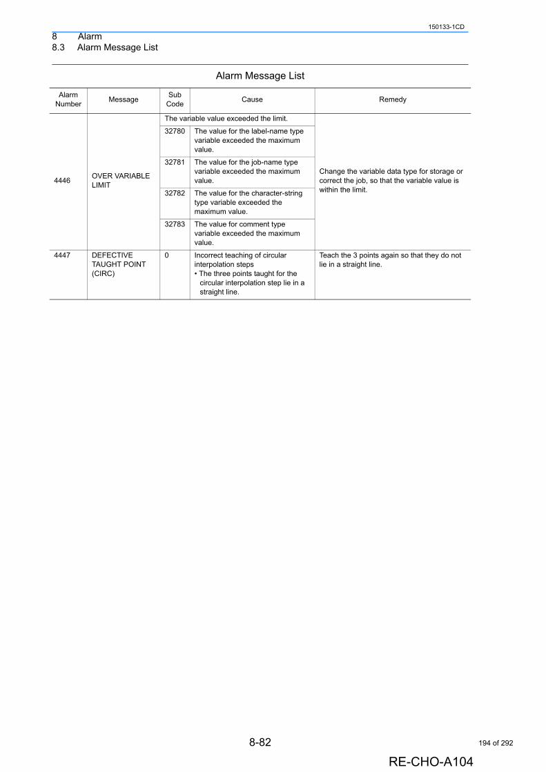
8 Alarm8.3 Alarm Message List
150133-1CD
4446OVER VARIABLE LIMIT
The variable value exceeded the limit.
Change the variable data type for storage or correct the job, so that the variable value is within the limit.
32780 The value for the label-name type variable exceeded the maximum value.
32781 The value for the job-name type variable exceeded the maximum value.
32782 The value for the character-string type variable exceeded the maximum value.
32783 The value for comment type variable exceeded the maximum value.
4447 DEFECTIVE TAUGHT POINT (CIRC)
0 Incorrect teaching of circular interpolation steps• The three points taught for the
circular interpolation step lie in a straight line.
Teach the 3 points again so that they do not lie in a straight line.
Alarm Message List
Alarm Number
MessageSub
CodeCause Remedy
8-82
RE-CHO-A104
194 of 292
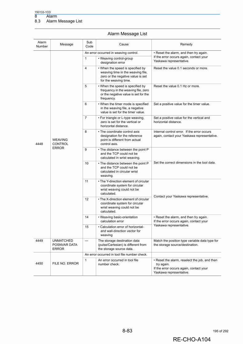
8 Alarm8.3 Alarm Message List
150133-1CD
4448WEAVING CONTROL ERROR
An error occurred in weaving control. • Reset the alarm, and then try again.If the error occurs again, contact your Yaskawa representative.
1 • Weaving control-group designation error
4 • When the speed is specified by weaving time in the weaving file, zero or the negative value is set for the weaving time.
Reset the value 0.1 seconds or more.
5 • When the speed is specified by frequency in the weaving file, zero or the negative value is set for the frequency.
Reset the value 0.1 Hz or more.
6 • When the timer mode is specified in the weaving file, a negative value is set for the timer value.
Set a positive value for the timer value.
7 • For triangle or L-type weaving, zero is set for the vertical or horizontal distance.
Set a positive value for the vertical and horizontal distance.
8 • The coordinate control axis designation for the reference point is different from actual control axis.
Internal control error. If the error occurs again, contact your Yaskawa representative.
9 • The distance between the point P and the TCP could not be calculated in wrist weaving.
Set the correct dimensions in the tool data.10 • The distance between the point P and the TCP could not be calculated in circular wrist weaving.
11 • The Y-direction element of circular coordinate system for circular wrist weaving could not be calculated.
Contact your Yaskawa representative.12 • The X-direction element of circular
coordinate system for circular wrist weaving could not be calculated.
14 • Weaving basic-orientation calculation error
• Reset the alarm, and then try again. If the error occurs again, contact your Yaskawa representative.15 • Calculation error of horizontal-
and wall-direction vector for weaving
4449 UNMATCHED POSNVAR DATA ERROR
--- The storage destination data (pulse/Cartesian) is different from the storage source data.
Match the position type variable data type for the storage source/destination.
4450 FILE NO. ERROR
An error occurred in tool file number check.
1 An error occurred in tool file number check.
• Reset the alarm, reselect the job, and then try again.
If the error occurs again, contact your Yaskawa representative.
Alarm Message List
Alarm Number
MessageSub
CodeCause Remedy
8-83
RE-CHO-A104
195 of 292
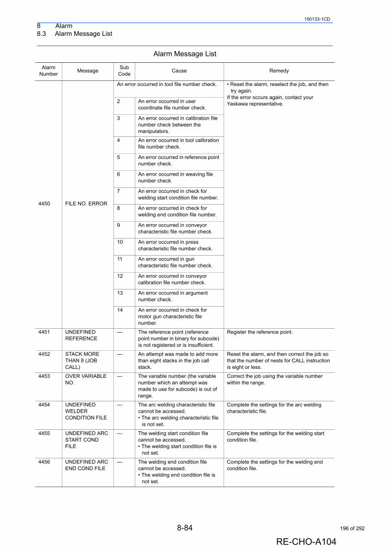
8 Alarm8.3 Alarm Message List
150133-1CD
4450 FILE NO. ERROR
An error occurred in tool file number check. • Reset the alarm, reselect the job, and then try again.
If the error occurs again, contact your Yaskawa representative.2 An error occurred in user
coordinate file number check.
3 An error occurred in calibration file number check between the manipulators.
4 An error occurred in tool calibration file number check.
5 An error occurred in reference point number check.
6 An error occurred in weaving file number check.
7 An error occurred in check for welding start condition file number.
8 An error occurred in check for welding end condition file number.
9 An error occurred in conveyor characteristic file number check.
10 An error occurred in press characteristic file number check.
11 An error occurred in gun characteristic file number check.
12 An error occurred in conveyor calibration file number check.
13 An error occurred in argument number check.
14 An error occurred in check for motor gun characteristic file number.
4451 UNDEFINED REFERENCE
--- The reference point (reference point number in binary for subcode) is not registered or is insufficient.
Register the reference point.
4452 STACK MORE THAN 8 (JOB CALL)
--- An attempt was made to add more than eight stacks in the job call stack.
Reset the alarm, and then correct the job so that the number of nests for CALL instruction is eight or less.
4453 OVER VARIABLE NO.
--- The variable number (the variable number which an attempt was made to use for subcode) is out of range.
Correct the job using the variable number within the range.
4454 UNDEFINED WELDER CONDITION FILE
--- The arc welding characteristic file cannot be accessed.• The arc welding characteristic file
is not set.
Complete the settings for the arc welding characteristic file.
4455 UNDEFINED ARC START COND FILE
--- The welding start condition file cannot be accessed.• The welding start condition file is
not set.
Complete the settings for the welding start condition file.
4456 UNDEFINED ARC END COND FILE
--- The welding end condition file cannot be accessed.• The welding end condition file is
not set.
Complete the settings for the welding end condition file.
Alarm Message List
Alarm Number
MessageSub
CodeCause Remedy
8-84
RE-CHO-A104
196 of 292
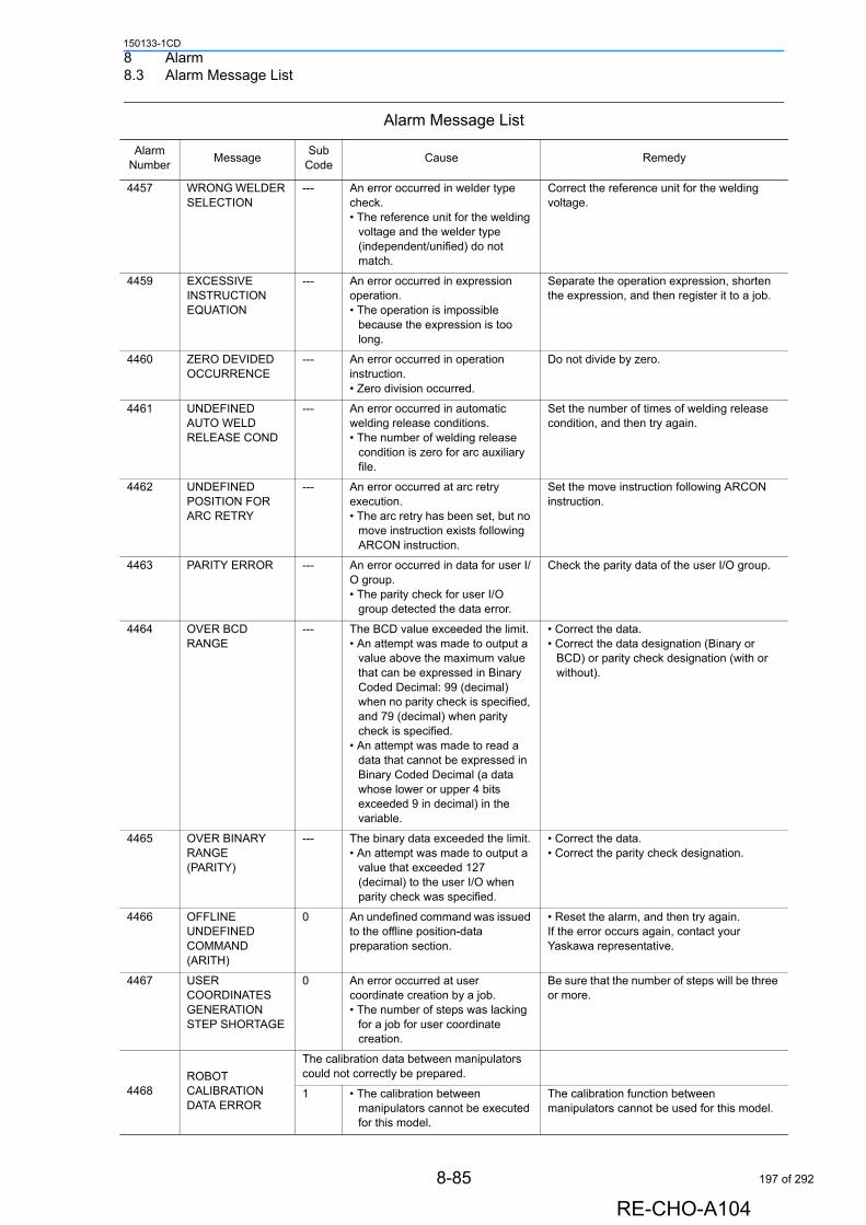
8 Alarm8.3 Alarm Message List
150133-1CD
4457 WRONG WELDER SELECTION
--- An error occurred in welder type check.• The reference unit for the welding
voltage and the welder type (independent/unified) do not match.
Correct the reference unit for the welding voltage.
4459 EXCESSIVE INSTRUCTION EQUATION
--- An error occurred in expression operation.• The operation is impossible
because the expression is too long.
Separate the operation expression, shorten the expression, and then register it to a job.
4460 ZERO DEVIDED OCCURRENCE
--- An error occurred in operation instruction.• Zero division occurred.
Do not divide by zero.
4461 UNDEFINED AUTO WELD RELEASE COND
--- An error occurred in automatic welding release conditions.• The number of welding release
condition is zero for arc auxiliary file.
Set the number of times of welding release condition, and then try again.
4462 UNDEFINED POSITION FOR ARC RETRY
--- An error occurred at arc retry execution.• The arc retry has been set, but no
move instruction exists following ARCON instruction.
Set the move instruction following ARCON instruction.
4463 PARITY ERROR --- An error occurred in data for user I/O group. • The parity check for user I/O
group detected the data error.
Check the parity data of the user I/O group.
4464 OVER BCD RANGE
--- The BCD value exceeded the limit.• An attempt was made to output a
value above the maximum value that can be expressed in Binary Coded Decimal: 99 (decimal) when no parity check is specified, and 79 (decimal) when parity check is specified.
• An attempt was made to read a data that cannot be expressed in Binary Coded Decimal (a data whose lower or upper 4 bits exceeded 9 in decimal) in the variable.
• Correct the data.• Correct the data designation (Binary or
BCD) or parity check designation (with or without).
4465 OVER BINARY RANGE (PARITY)
--- The binary data exceeded the limit.• An attempt was made to output a
value that exceeded 127 (decimal) to the user I/O when parity check was specified.
• Correct the data.• Correct the parity check designation.
4466 OFFLINE UNDEFINED COMMAND (ARITH)
0 An undefined command was issued to the offline position-data preparation section.
• Reset the alarm, and then try again. If the error occurs again, contact your Yaskawa representative.
4467 USER COORDINATES GENERATION STEP SHORTAGE
0 An error occurred at user coordinate creation by a job.• The number of steps was lacking
for a job for user coordinate creation.
Be sure that the number of steps will be three or more.
4468ROBOT CALIBRATION DATA ERROR
The calibration data between manipulators could not correctly be prepared.
1 • The calibration between manipulators cannot be executed for this model.
The calibration function between manipulators cannot be used for this model.
Alarm Message List
Alarm Number
MessageSub
CodeCause Remedy
8-85
RE-CHO-A104
197 of 292
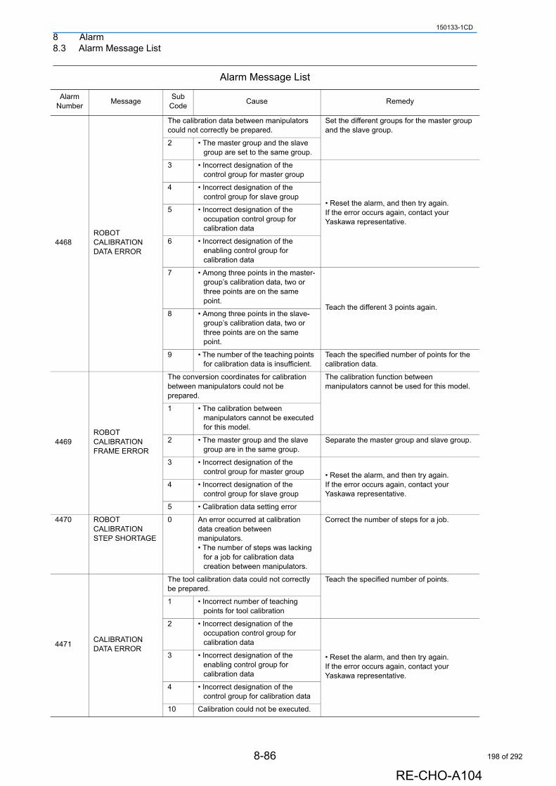
8 Alarm8.3 Alarm Message List
150133-1CD
4468ROBOT CALIBRATION DATA ERROR
The calibration data between manipulators could not correctly be prepared.
Set the different groups for the master group and the slave group.
2 • The master group and the slave group are set to the same group.
3 • Incorrect designation of the control group for master group
• Reset the alarm, and then try again. If the error occurs again, contact your Yaskawa representative.
4 • Incorrect designation of the control group for slave group
5 • Incorrect designation of the occupation control group for calibration data
6 • Incorrect designation of the enabling control group for calibration data
7 • Among three points in the master-group’s calibration data, two or three points are on the same point.
Teach the different 3 points again.8 • Among three points in the slave-
group’s calibration data, two or three points are on the same point.
9 • The number of the teaching points for calibration data is insufficient.
Teach the specified number of points for the calibration data.
4469ROBOT CALIBRATION FRAME ERROR
The conversion coordinates for calibration between manipulators could not be prepared.
The calibration function between manipulators cannot be used for this model.
1 • The calibration between manipulators cannot be executed for this model.
2 • The master group and the slave group are in the same group.
Separate the master group and slave group.
3 • Incorrect designation of the control group for master group • Reset the alarm, and then try again.
If the error occurs again, contact your Yaskawa representative.
4 • Incorrect designation of the control group for slave group
5 • Calibration data setting error
4470 ROBOT CALIBRATION STEP SHORTAGE
0 An error occurred at calibration data creation between manipulators.• The number of steps was lacking
for a job for calibration data creation between manipulators.
Correct the number of steps for a job.
4471CALIBRATION DATA ERROR
The tool calibration data could not correctly be prepared.
Teach the specified number of points.
1 • Incorrect number of teaching points for tool calibration
2 • Incorrect designation of the occupation control group for calibration data
• Reset the alarm, and then try again. If the error occurs again, contact your Yaskawa representative.
3 • Incorrect designation of the enabling control group for calibration data
4 • Incorrect designation of the control group for calibration data
10 Calibration could not be executed.
Alarm Message List
Alarm Number
MessageSub
CodeCause Remedy
8-86
RE-CHO-A104
198 of 292
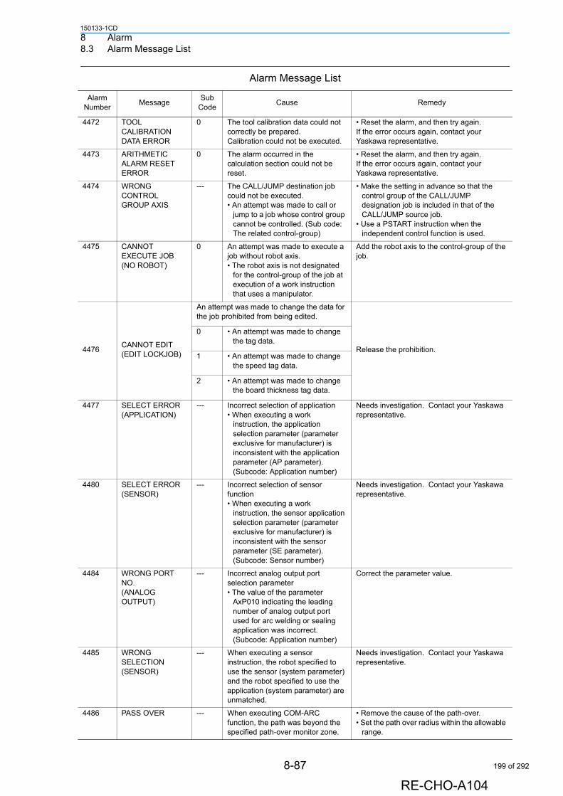
8 Alarm8.3 Alarm Message List
150133-1CD
4472 TOOL CALIBRATION DATA ERROR
0 The tool calibration data could not correctly be prepared.Calibration could not be executed.
• Reset the alarm, and then try again. If the error occurs again, contact your Yaskawa representative.
4473 ARITHMETIC ALARM RESET ERROR
0 The alarm occurred in the calculation section could not be reset.
• Reset the alarm, and then try again. If the error occurs again, contact your Yaskawa representative.
4474 WRONG CONTROL GROUP AXIS
--- The CALL/JUMP destination job could not be executed.• An attempt was made to call or
jump to a job whose control group cannot be controlled. (Sub code: The related control-group)
• Make the setting in advance so that the control group of the CALL/JUMP designation job is included in that of the CALL/JUMP source job.
• Use a PSTART instruction when the independent control function is used.
4475 CANNOT EXECUTE JOB (NO ROBOT)
0 An attempt was made to execute a job without robot axis.• The robot axis is not designated
for the control-group of the job at execution of a work instruction that uses a manipulator.
Add the robot axis to the control-group of the job.
4476CANNOT EDIT (EDIT LOCKJOB)
An attempt was made to change the data for the job prohibited from being edited.
Release the prohibition.
0 • An attempt was made to change the tag data.
1 • An attempt was made to change the speed tag data.
2 • An attempt was made to change the board thickness tag data.
4477 SELECT ERROR (APPLICATION)
--- Incorrect selection of application• When executing a work
instruction, the application selection parameter (parameter exclusive for manufacturer) is inconsistent with the application parameter (AP parameter). (Subcode: Application number)
Needs investigation. Contact your Yaskawa representative.
4480 SELECT ERROR (SENSOR)
--- Incorrect selection of sensor function• When executing a work
instruction, the sensor application selection parameter (parameter exclusive for manufacturer) is inconsistent with the sensor parameter (SE parameter). (Subcode: Sensor number)
Needs investigation. Contact your Yaskawa representative.
4484 WRONG PORT NO. (ANALOG OUTPUT)
--- Incorrect analog output port selection parameter• The value of the parameter
AxP010 indicating the leading number of analog output port used for arc welding or sealing application was incorrect. (Subcode: Application number)
Correct the parameter value.
4485 WRONG SELECTION (SENSOR)
--- When executing a sensor instruction, the robot specified to use the sensor (system parameter) and the robot specified to use the application (system parameter) are unmatched.
Needs investigation. Contact your Yaskawa representative.
4486 PASS OVER --- When executing COM-ARC function, the path was beyond the specified path-over monitor zone.
• Remove the cause of the path-over.• Set the path over radius within the allowable
range.
Alarm Message List
Alarm Number
MessageSub
CodeCause Remedy
8-87
RE-CHO-A104
199 of 292

8 Alarm8.3 Alarm Message List
150133-1CD
4487 WRONG MECH PARAMETER FILE
0 An error occurred in mechanical parameter for the path control section.
• Reset the alarm, and then try again. If the error occurs again, contact your Yaskawa representative.
4488 PT frame not completed
--- PT frame not completed • This alarm does not occur. (No alarm data is used.)
4489DEFECTIVE TAUGHT POINT (CUTTING)
The CUT instruction could not be executed. Set zero pulse for the C-and W-axis position at the cutting start position.1 • The C- and W-axis position at the
cutting start position is not zero pulse.
2 • Zero is set for the cutting radius. Set a value bigger than 0 for the radius.
3 • The cutting machine axis is not mounted.
The CUT instruction can be used for the manipulator with small-circle cutting axis only.
4 • This manipulator cannot perform a hexagonal cutting motion.
This robot cannot perform a hexagonal cutting motion. Select an other cutting form.
4490DEFECTIVE TAUGHT POINT (ENDLESS)
The Endless motion could not be performed. To perform an interpolation motion such as MOVL and MOVC after an Endless rotation, execute an MRESET instruction beforehand.
1 • After the Endless rotation completed, an attempt was made to execute an interpolation instruction such as MOVL and MOVC before executing an MRESET instruction.
2 • The base axis is set as an Endless rotation axis. The Endless function cannot be used with the base axis. Change the parameter setting that
designates the Endless rotation axis.3 • An attempt was made to execute
the Endless function although the endless axis was not designated.
4 • The Endless axis exceeded the maximum pulse value (±536870911).
Correct the rotation amount so that the Endless axis does not exceed the maximum pulse value.
4491CORRECTIONAL DIRECTION ERROR
An error occurred in the calculation section for the correcting direction at path correcting motion.
• Reset the alarm, and then try again.If the error occurs again, contact your Yaskawa representative.
1 • Control-group designation error for correcting-direction preparation
2 • Designation error for the correcting-direction coordinates
3 • When “any direction” is set for the correcting direction, the correction coordinates is not prepared.
Teach the correcting direction with the reference point (REFP).
4 • When “any direction” is set for the correcting direction, the reference points (REFP) are taught on the same point.
Teach the reference points (REFP) so that each point is different.
5 • Designation error for the coordinated motion control axis at the reference point
• Reset the alarm, and then try again.If the error occurs again, contact your Yaskawa representative.
Alarm Message List
Alarm Number
MessageSub
CodeCause Remedy
8-88
RE-CHO-A104
200 of 292
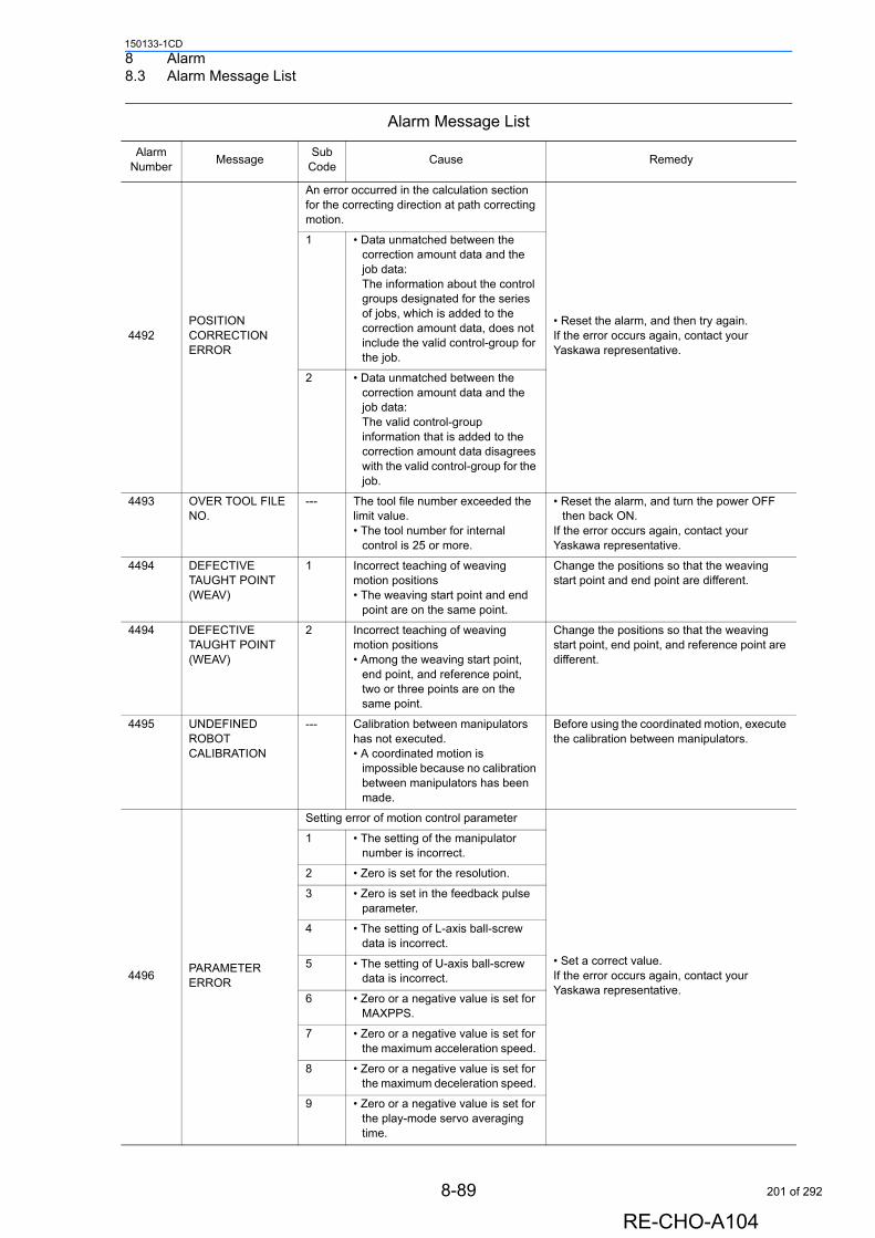
8 Alarm8.3 Alarm Message List
150133-1CD
4492POSITION CORRECTION ERROR
An error occurred in the calculation section for the correcting direction at path correcting motion.
• Reset the alarm, and then try again.If the error occurs again, contact your Yaskawa representative.
1 • Data unmatched between the correction amount data and the job data:The information about the control groups designated for the series of jobs, which is added to the correction amount data, does not include the valid control-group for the job.
2 • Data unmatched between the correction amount data and the job data:The valid control-group information that is added to the correction amount data disagrees with the valid control-group for the job.
4493 OVER TOOL FILE NO.
--- The tool file number exceeded the limit value.• The tool number for internal
control is 25 or more.
• Reset the alarm, and turn the power OFF then back ON.
If the error occurs again, contact your Yaskawa representative.
4494 DEFECTIVE TAUGHT POINT (WEAV)
1 Incorrect teaching of weaving motion positions• The weaving start point and end
point are on the same point.
Change the positions so that the weaving start point and end point are different.
4494 DEFECTIVE TAUGHT POINT (WEAV)
2 Incorrect teaching of weaving motion positions• Among the weaving start point,
end point, and reference point, two or three points are on the same point.
Change the positions so that the weaving start point, end point, and reference point are different.
4495 UNDEFINED ROBOT CALIBRATION
--- Calibration between manipulators has not executed.• A coordinated motion is
impossible because no calibration between manipulators has been made.
Before using the coordinated motion, execute the calibration between manipulators.
4496PARAMETER ERROR
Setting error of motion control parameter
• Set a correct value. If the error occurs again, contact your Yaskawa representative.
1 • The setting of the manipulator number is incorrect.
2 • Zero is set for the resolution.
3 • Zero is set in the feedback pulse parameter.
4 • The setting of L-axis ball-screw data is incorrect.
5 • The setting of U-axis ball-screw data is incorrect.
6 • Zero or a negative value is set for MAXPPS.
7 • Zero or a negative value is set for the maximum acceleration speed.
8 • Zero or a negative value is set for the maximum deceleration speed.
9 • Zero or a negative value is set for the play-mode servo averaging time.
Alarm Message List
Alarm Number
MessageSub
CodeCause Remedy
8-89
RE-CHO-A104
201 of 292
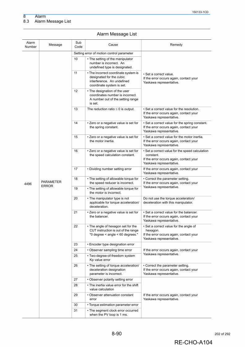
8 Alarm8.3 Alarm Message List
150133-1CD
4496PARAMETER ERROR
Setting error of motion control parameter
• Set a correct value. If the error occurs again, contact your Yaskawa representative.
10 • The setting of the manipulator number is incorrect. An undefined type is designated.
11 • The incorrect coordinate system is designated for the cubic interference. An undefined coordinate system is set.
12 • The designation of the user coordinates number is incorrect. A number out of the setting range is set.
13 The reduction ratio ≤ 0 is output. • Set a correct value for the resolution. If the error occurs again, contact your Yaskawa representative.
14 • Zero or a negative value is set for the spring constant.
• Set a correct value for the spring constant. If the error occurs again, contact your Yaskawa representative.
15 • Zero or a negative value is set for the motor inertia.
• Set a correct value for the motor inertia. If the error occurs again, contact your Yaskawa representative.
16 • Zero or a negative value is set for the speed calculation constant.
• Set a correct value for the speed calculation constant.
If the error occurs again, contact your Yaskawa representative.
17 • Dividing number setting error If the error occurs again, contact your Yaskawa representative.
18 • The setting of allowable torque for the speed reducer is incorrect.
• Correct the parameter setting. If the error occurs again, contact your Yaskawa representative.19 • The setting of allowable torque for
the motor is incorrect.
20 • The manipulator type is not applicable for torque acceleration/deceleration.
Do not use the torque acceleration/deceleration with this manipulator.
21 • Zero or a negative value is set for the balancer.
• Set a correct value for the balancer. If the error occurs again, contact your Yaskawa representative.
22 • The angle of hexagon set for the CUT instruction is out of the range "0 degree < angle < 60 degrees."
• Set a correct value for the angle of hexagon.
If the error occurs again, contact your Yaskawa representative.
23 • Encoder type designation error
If the error occurs again, contact your Yaskawa representative.
24 • Observer sampling time error
25 • Two-degree-of-freedom system Kp value error
26 • The setting of torque acceleration/deceleration designation parameter is incorrect.
• Correct the parameter setting.If the error occurs again, contact your Yaskawa representative.
27 • Observer polarity setting error
If the error occurs again, contact your Yaskawa representative.
28 • The inertia value error for the shift value calculation
29 • Observer attenuation constant error
30 • Torque estimation parameter error
31 • The segment clock error occurred when the PV loop is 1 ms.
Alarm Message List
Alarm Number
MessageSub
CodeCause Remedy
8-90
RE-CHO-A104
202 of 292
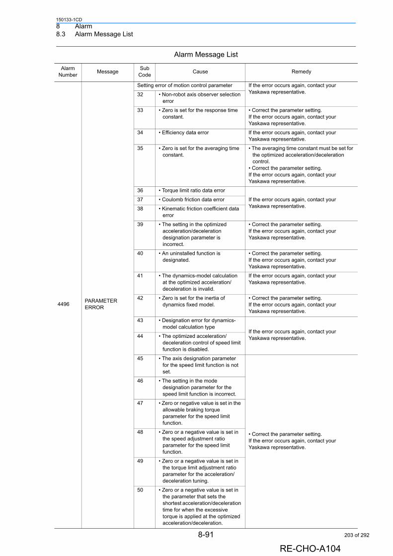
8 Alarm8.3 Alarm Message List
150133-1CD
4496PARAMETER ERROR
Setting error of motion control parameter If the error occurs again, contact your Yaskawa representative.32 • Non-robot axis observer selection
error
33 • Zero is set for the response time constant.
• Correct the parameter setting.If the error occurs again, contact your Yaskawa representative.
34 • Efficiency data error If the error occurs again, contact your Yaskawa representative.
35 • Zero is set for the averaging time constant.
• The averaging time constant must be set for the optimized acceleration/deceleration control.
• Correct the parameter setting. If the error occurs again, contact your Yaskawa representative.
36 • Torque limit ratio data error
If the error occurs again, contact your Yaskawa representative.
37 • Coulomb friction data error
38 • Kinematic friction coefficient data error
39 • The setting in the optimized acceleration/deceleration designation parameter is incorrect.
• Correct the parameter setting.If the error occurs again, contact your Yaskawa representative.
40 • An uninstalled function is designated.
• Correct the parameter setting. If the error occurs again, contact your Yaskawa representative.
41 • The dynamics-model calculation at the optimized acceleration/deceleration is invalid.
If the error occurs again, contact your Yaskawa representative.
42 • Zero is set for the inertia of dynamics fixed model.
• Correct the parameter setting. If the error occurs again, contact your Yaskawa representative.
43 • Designation error for dynamics-model calculation type
If the error occurs again, contact your Yaskawa representative.44 • The optimized acceleration/
deceleration control of speed limit function is disabled.
45 • The axis designation parameter for the speed limit function is not set.
• Correct the parameter setting.If the error occurs again, contact your Yaskawa representative.
46 • The setting in the mode designation parameter for the speed limit function is incorrect.
47 • Zero or negative value is set in the allowable braking torque parameter for the speed limit function.
48 • Zero or a negative value is set in the speed adjustment ratio parameter for the speed limit function.
49 • Zero or a negative value is set in the torque limit adjustment ratio parameter for the acceleration/deceleration tuning.
50 • Zero or a negative value is set in the parameter that sets the shortest acceleration/deceleration time for when the excessive torque is applied at the optimized
Alarm Message List
Alarm Number
MessageSub
CodeCause Remedy
8-91
RE-CHO-A104
acceleration/deceleration.
203 of 292
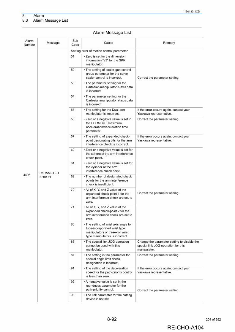
8 Alarm8.3 Alarm Message List
150133-1CD
4496PARAMETER ERROR
Setting error of motion control parameter
Correct the parameter setting.
51 • Zero is set for the dimension information "a3" for the SKR manipulator.
52 • The setting of sealer-gun control-group parameter for the servo sealer control is incorrect.
53 • The parameter setting for the Cartesian manipulator X-axis data is incorrect.
54 • The parameter setting for the Cartesian manipulator Y-axis data is incorrect.
55 • The setting for the Dual-arm manipulator is incorrect.
If the error occurs again, contact your Yaskawa representative.
56 • Zero or a negative value is set in the FORMCUT maximum acceleration/deceleration time parameter.
Correct the parameter setting.
57 • The setting of expanded check-point designating bits for the arm interference check is incorrect.
If the error occurs again, contact your Yaskawa representative.
60 • Zero or a negative value is set for the sphere at the arm interference check point.
Correct the parameter setting.
61 • Zero or a negative value is set for the cylinder at the arm interference check point.
62 • The number of designated check points for the arm interference check is insufficient.
70 • All of X, Y, and Z value of the expanded check-point 1 for the arm interference check are set to zero.
71 • All of X, Y, and Z value of the expanded check-point 2 for the arm interference check are set to zero.
85 • The setting of wrist axis angle for tube-incorporated wrist type manipulators or three-roll wrist type manipulators is incorrect.
86 • The special link JOG operation cannot be used with this manipulator.
Change the parameter setting to disable the special link JOG operation for this manipulator.
87 • The setting in the parameter for special angle limit check designation is incorrect.
Correct the parameter setting.
91 • The setting of the deceleration speed for the path-priority control is less than zero.
If the error occurs again, contact your Yaskawa representative.
92 • A negative value is set in the roundness parameter for the path-priority control. Correct the parameter setting.
93 • The link parameter for the cutting device is not set.
Alarm Message List
Alarm Number
MessageSub
CodeCause Remedy
8-92
RE-CHO-A104
204 of 292
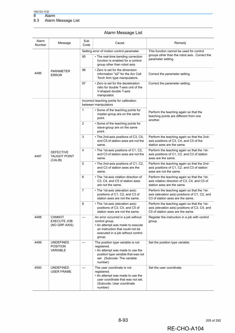
8 Alarm8.3 Alarm Message List
150133-1CD
4496PARAMETER ERROR
Setting error of motion control parameter This function cannot be used for control groups other than the robot axis. Correct the parameter setting.
95 • The real-time bending correction function is enabled for a control-group other than robot axis.
96 • Zero is set for the dimension information "a2" for the Arc Cell Torch Arm type manipulators.
Correct the parameter setting.
97 • Zero is set for the deceleration ratio for double T-axis unit of the V-shaped double T-axis manipulator.
Correct the parameter setting.
4497DEFECTIVE TAUGHT POINT (CALIB)
Incorrect teaching points for calibration between manipulators
Perform the teaching again so that the teaching points are different from one another.
1 • Some of the teaching points for master-group are on the same point.
2 • Some of the teaching points for slave-group are on the same point.
3 • The 2nd-axis positions of C3, C4, and C5 of station axes are not the same.
Perform the teaching again so that the 2nd-axis positions of C3, C4, and C5 of the station axes are the same.
4 • The 1st-axis positions of C1, C2, and C3 of station axes are not the same.
Perform the teaching again so that the 1st-axis positions of C1, C2, and C3 of station axes are the same.
5 • The 2nd-axis positions of C1, C2, and C3 of station axes are the same.
Perform the teaching again so that the 2nd-axis positions of C1, C2, and C3 of station axes are not the same.
6 • The 1st-axis rotation direction of C3, C4, and C5 of station axes are not the same.
Perform the teaching again so that the 1st-axis rotation direction of C3, C4, and C5 of station axes are the same.
7 • The 1st-axis (elevation axis) positions of C1, C2, and C3 of station axes are not the same.
Perform the teaching again so that the 1st-axis (elevation axis) positions of C1, C2, and C3 of station axes are the same.
8 • The 1st-axis (elevation axis) positions of C3, C4, and C5 of station axes are not the same.
Perform the teaching again so that the 1st-axis (elevation axis) positions of C3, C4, and C5 of station axes are the same.
4498 CANNOT EXECUTE JOB (NO GRP AXIS)
--- An error occurred in a job without control group.• An attempt was made to execute
an instruction that could not be executed in a job without control group.
Register the instruction in a job with control group.
4499 UNDEFINED POSITION VARIABLE
--- The position type variable is not registered.• An attempt was made to use the
position type variable that was not set. (Subcode: The variable number)
Set the position type variable.
4500 UNDEFINED USER FRAME
--- The user coordinate is not registered.• An attempt was made to use the
user coordinate that was not set. (Subcode: User coordinate number)
Set the user coordinate.
Alarm Message List
Alarm Number
MessageSub
CodeCause Remedy
8-93
RE-CHO-A104
205 of 292
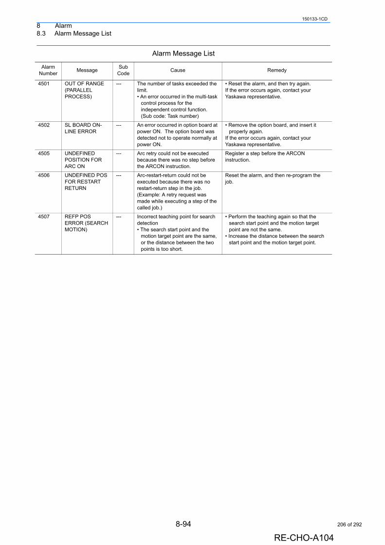
8 Alarm8.3 Alarm Message List
150133-1CD
4501 OUT OF RANGE (PARALLEL PROCESS)
--- The number of tasks exceeded the limit.• An error occurred in the multi-task
control process for the independent control function. (Sub code: Task number)
• Reset the alarm, and then try again. If the error occurs again, contact your Yaskawa representative.
4502 SL BOARD ON-LINE ERROR
--- An error occurred in option board at power ON. The option board was detected not to operate normally at power ON.
• Remove the option board, and insert it properly again.
If the error occurs again, contact your Yaskawa representative.
4505 UNDEFINED POSITION FOR ARC ON
--- Arc retry could not be executed because there was no step before the ARCON instruction.
Register a step before the ARCON instruction.
4506 UNDEFINED POS FOR RESTART RETURN
--- Arc-restart-return could not be executed because there was no restart-return step in the job. (Example: A retry request was made while executing a step of the called job.)
Reset the alarm, and then re-program the job.
4507 REFP POS ERROR (SEARCH MOTION)
--- Incorrect teaching point for search detection• The search start point and the
motion target point are the same, or the distance between the two points is too short.
• Perform the teaching again so that the search start point and the motion target point are not the same.
• Increase the distance between the search start point and the motion target point.
Alarm Message List
Alarm Number
MessageSub
CodeCause Remedy
8-94
RE-CHO-A104
206 of 292
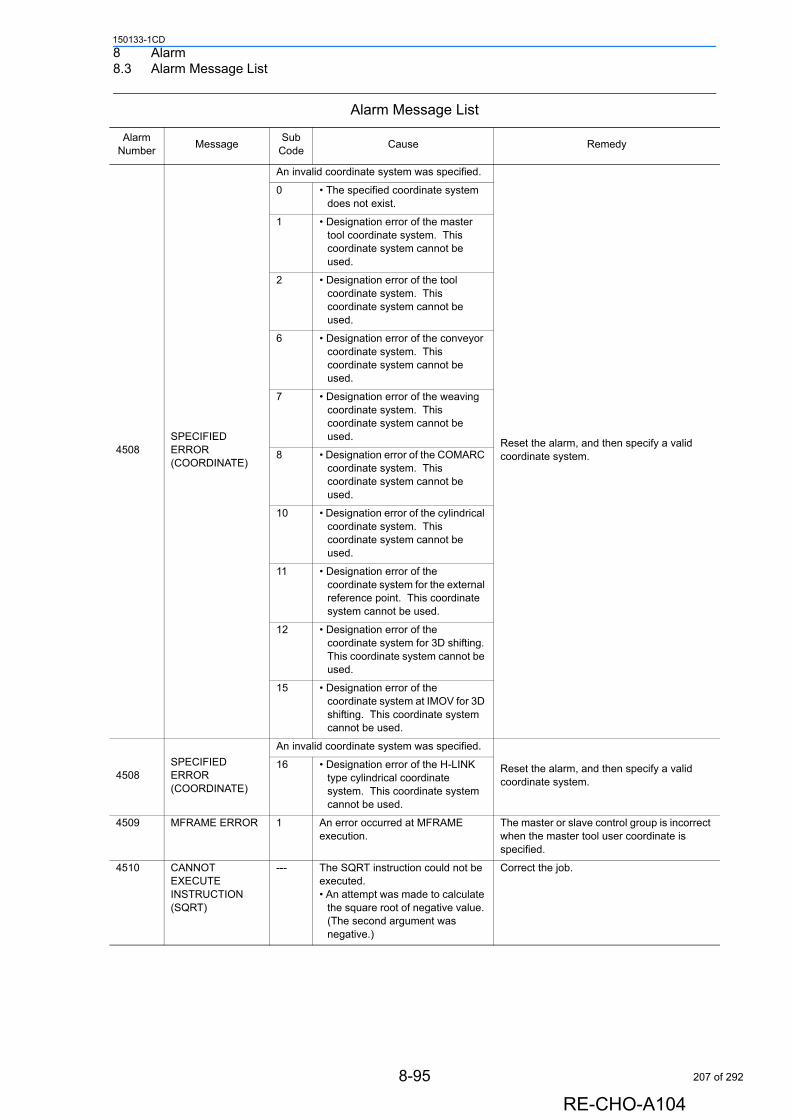
8 Alarm8.3 Alarm Message List
150133-1CD
4508SPECIFIED ERROR (COORDINATE)
An invalid coordinate system was specified.
Reset the alarm, and then specify a valid coordinate system.
0 • The specified coordinate system does not exist.
1 • Designation error of the master tool coordinate system. This coordinate system cannot be used.
2 • Designation error of the tool coordinate system. This coordinate system cannot be used.
6 • Designation error of the conveyor coordinate system. This coordinate system cannot be used.
7 • Designation error of the weaving coordinate system. This coordinate system cannot be used.
8 • Designation error of the COMARC coordinate system. This coordinate system cannot be used.
10 • Designation error of the cylindrical coordinate system. This coordinate system cannot be used.
11 • Designation error of the coordinate system for the external reference point. This coordinate system cannot be used.
12 • Designation error of the coordinate system for 3D shifting. This coordinate system cannot be used.
15 • Designation error of the coordinate system at IMOV for 3D shifting. This coordinate system cannot be used.
4508SPECIFIED ERROR (COORDINATE)
An invalid coordinate system was specified.
Reset the alarm, and then specify a valid coordinate system.
16 • Designation error of the H-LINK type cylindrical coordinate system. This coordinate system cannot be used.
4509 MFRAME ERROR 1 An error occurred at MFRAME execution.
The master or slave control group is incorrect when the master tool user coordinate is specified.
4510 CANNOT EXECUTE INSTRUCTION (SQRT)
--- The SQRT instruction could not be executed.• An attempt was made to calculate
the square root of negative value. (The second argument was negative.)
Correct the job.
Alarm Message List
Alarm Number
MessageSub
CodeCause Remedy
8-95
RE-CHO-A104
207 of 292
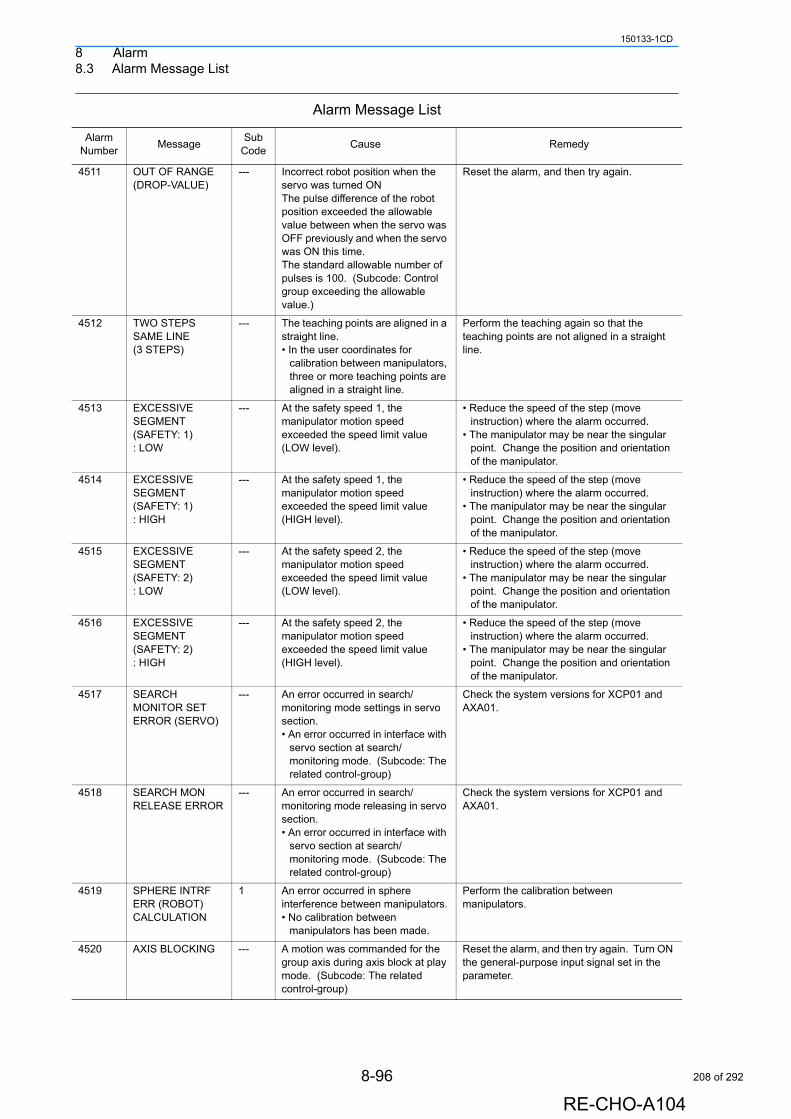
8 Alarm8.3 Alarm Message List
150133-1CD
4511 OUT OF RANGE (DROP-VALUE)
--- Incorrect robot position when the servo was turned ONThe pulse difference of the robot position exceeded the allowable value between when the servo was OFF previously and when the servo was ON this time. The standard allowable number of pulses is 100. (Subcode: Control group exceeding the allowable value.)
Reset the alarm, and then try again.
4512 TWO STEPS SAME LINE (3 STEPS)
--- The teaching points are aligned in a straight line.• In the user coordinates for
calibration between manipulators, three or more teaching points are aligned in a straight line.
Perform the teaching again so that the teaching points are not aligned in a straight line.
4513 EXCESSIVE SEGMENT (SAFETY: 1) : LOW
--- At the safety speed 1, the manipulator motion speed exceeded the speed limit value (LOW level).
• Reduce the speed of the step (move instruction) where the alarm occurred.
• The manipulator may be near the singular point. Change the position and orientation of the manipulator.
4514 EXCESSIVE SEGMENT (SAFETY: 1) : HIGH
--- At the safety speed 1, the manipulator motion speed exceeded the speed limit value (HIGH level).
• Reduce the speed of the step (move instruction) where the alarm occurred.
• The manipulator may be near the singular point. Change the position and orientation of the manipulator.
4515 EXCESSIVE SEGMENT (SAFETY: 2) : LOW
--- At the safety speed 2, the manipulator motion speed exceeded the speed limit value (LOW level).
• Reduce the speed of the step (move instruction) where the alarm occurred.
• The manipulator may be near the singular point. Change the position and orientation of the manipulator.
4516 EXCESSIVE SEGMENT (SAFETY: 2) : HIGH
--- At the safety speed 2, the manipulator motion speed exceeded the speed limit value (HIGH level).
• Reduce the speed of the step (move instruction) where the alarm occurred.
• The manipulator may be near the singular point. Change the position and orientation of the manipulator.
4517 SEARCH MONITOR SET ERROR (SERVO)
--- An error occurred in search/monitoring mode settings in servo section.• An error occurred in interface with
servo section at search/monitoring mode. (Subcode: The related control-group)
Check the system versions for XCP01 and AXA01.
4518 SEARCH MON RELEASE ERROR
--- An error occurred in search/monitoring mode releasing in servo section.• An error occurred in interface with
servo section at search/monitoring mode. (Subcode: The related control-group)
Check the system versions for XCP01 and AXA01.
4519 SPHERE INTRF ERR (ROBOT) CALCULATION
1 An error occurred in sphere interference between manipulators.• No calibration between
manipulators has been made.
Perform the calibration between manipulators.
4520 AXIS BLOCKING --- A motion was commanded for the group axis during axis block at play mode. (Subcode: The related control-group)
Reset the alarm, and then try again. Turn ON the general-purpose input signal set in the parameter.
Alarm Message List
Alarm Number
MessageSub
CodeCause Remedy
8-96
RE-CHO-A104
208 of 292
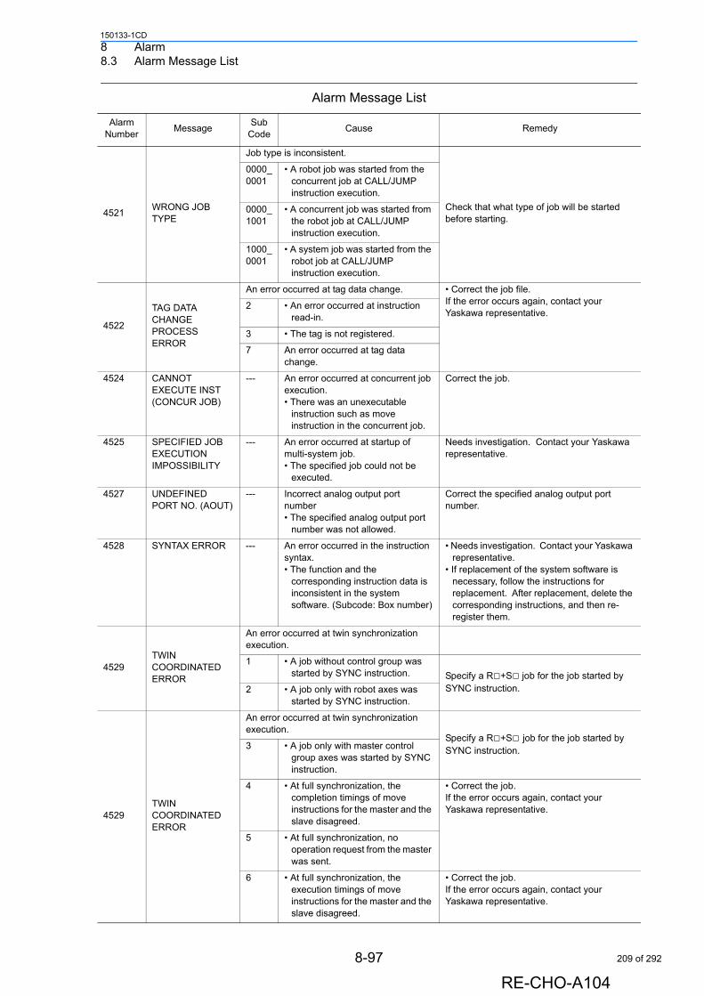
8 Alarm8.3 Alarm Message List
150133-1CD
4521WRONG JOB TYPE
Job type is inconsistent.
Check that what type of job will be started before starting.
0000_0001
• A robot job was started from the concurrent job at CALL/JUMP instruction execution.
0000_1001
• A concurrent job was started from the robot job at CALL/JUMP instruction execution.
1000_0001
• A system job was started from the robot job at CALL/JUMP instruction execution.
4522
TAG DATA CHANGE PROCESS ERROR
An error occurred at tag data change. • Correct the job file.If the error occurs again, contact your Yaskawa representative.
2 • An error occurred at instruction read-in.
3 • The tag is not registered.
7 An error occurred at tag data change.
4524 CANNOT EXECUTE INST (CONCUR JOB)
--- An error occurred at concurrent job execution.• There was an unexecutable
instruction such as move instruction in the concurrent job.
Correct the job.
4525 SPECIFIED JOB EXECUTION IMPOSSIBILITY
--- An error occurred at startup of multi-system job.• The specified job could not be
executed.
Needs investigation. Contact your Yaskawa representative.
4527 UNDEFINED PORT NO. (AOUT)
--- Incorrect analog output port number• The specified analog output port
number was not allowed.
Correct the specified analog output port number.
4528 SYNTAX ERROR --- An error occurred in the instruction syntax.• The function and the
corresponding instruction data is inconsistent in the system software. (Subcode: Box number)
• Needs investigation. Contact your Yaskawa representative.
• If replacement of the system software is necessary, follow the instructions for replacement. After replacement, delete the corresponding instructions, and then re-register them.
4529TWIN COORDINATED ERROR
An error occurred at twin synchronization execution.
1 • A job without control group was started by SYNC instruction. Specify a R□+S□ job for the job started by
SYNC instruction.2 • A job only with robot axes was started by SYNC instruction.
4529TWIN COORDINATED ERROR
An error occurred at twin synchronization execution.
Specify a R□+S□ job for the job started by SYNC instruction.3 • A job only with master control
group axes was started by SYNC instruction.
4 • At full synchronization, the completion timings of move instructions for the master and the slave disagreed.
• Correct the job.If the error occurs again, contact your Yaskawa representative.
5 • At full synchronization, no operation request from the master was sent.
6 • At full synchronization, the execution timings of move instructions for the master and the slave disagreed.
• Correct the job.If the error occurs again, contact your Yaskawa representative.
Alarm Message List
Alarm Number
MessageSub
CodeCause Remedy
8-97
RE-CHO-A104
209 of 292
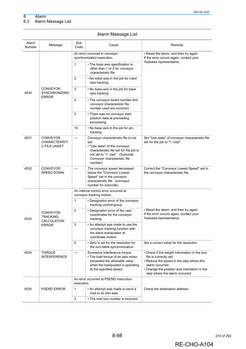
8 Alarm8.3 Alarm Message List
150133-1CD
4530CONVEYOR SYNCHRONIZING ERROR
An error occurred in conveyor synchronization execution.
• Reset the alarm, and then try again.If the error occurs again, contact your Yaskawa representative.
1 • The base axis specification is other than 1 or 2 for conveyor characteristic file.
2 • No robot axis in the job for robot axis tracking
3 • No base axis in the job for base axis tracking
4 • The conveyor board number and conveyor characteristic file number used are incorrect.
5 • There was no conveyor start position data at prereading processing.
10 • No base axis in the job for arc tracking
4531 CONVEYOR CHARACTERISTIC FILE UNSET
--- Conveyor characteristic file is not set.• "Use state" of the conveyor
characteristic file set for the job is not set to "1: Use". (Subcode: Conveyor characteristic file number)
Set "Use state" of conveyor characteristic file set for the job to "1: Use".
4532 CONVEYOR SPEED DOWN
--- The conveyor speed decreased below the "Conveyor Lowest Speed" set in the conveyor characteristic file. (conveyor number for subcode)
Correct the "Conveyor Lowest Speed" set in the conveyor characteristic file.
4533
CONVEYOR TRACKING CALCULATIONERROR
An internal control error occurred at conveyor tracking motion.
• Reset the alarm, and then try again. If the error occurs again, contact your Yaskawa representative.
1 • Designation error of the conveyor tracking control-group
2 • Designation error of the user coordinates for the conveyor tracking
3 • An attempt was made to use the conveyor tracking function with the slave manipulator at coordinate motion.
4 • Zero is set for the resolution for the turn-table synchronization.
Set a correct value for the resolution.
4534 TORQUE INTERFERENCE
--- Excessive interference torque• The load torque of an axis motor
exceeded the allowable value when the manipulator is operating at the specified speed.
• Check if the weight information in the tool file is correctly set.
• Reduce the speed in the step where the alarm occurred.
• Change the position and orientation in the step where the alarm occurred.
4535 PSEND ERROR
An error occurred at PSEND instruction execution.
Check the destination address.1 • An attempt was made to send a mail to its own task.
3 • The mail box number is incorrect.
Alarm Message List
Alarm Number
MessageSub
CodeCause Remedy
8-98
RE-CHO-A104
210 of 292
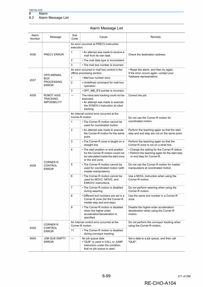
8 Alarm8.3 Alarm Message List
150133-1CD
4536 PRECV ERROR
An error occurred at PRECV instruction execution.
Check the destination address.1 • An attempt was made to receive a
mail from its own task.
2 • The mail data type is inconsistent.
3 • The mail box number is incorrect.
4537
OFFLINEMAIL BOX PROCESSING ERROR
An error occurred in mail box control in the offline processing section.
• Reset the alarm, and then try again.If the error occurs again, contact your Yaskawa representative.1 • Mail box number error
2 • Undefined command for mail box operation
3 • OFF_MB_IFS pointer is incorrect.
4538 ROBOT AXIS TRACKING IMPOSIBILITY
--- The robot axis tracking could not be executed.• An attempt was made to execute
the SYMOVJ instruction at robot tracking.
Correct the job.
4539CORNER R CONTROL ERROR
An internal control error occurred at the Corner-R motion. Do not use the Corner-R motion for
coordinated motion.1 • The Corner-R motion cannot be used for coordinated motion.
2 • An attempt was made to execute the Corner-R motion for the same point.
Perform the teaching again so that the start step and end step are not on the same point.
3 • The Corner-R zone is taught on a straight line.
Perform the teaching again so that the Corner-R zone is not on a strait line.
4 • The start position or end position for the Corner-R motion could not be calculated inside the start zone or the end zone.
• Change the setting for the Corner-R radius. • Perform the teaching again for the start step
or end step for Corner-R.
5 • The Corner-R motion cannot be used for coordinated motion (with master manipulators).
Do not use the Corner-R motion for master manipulators at coordinated motion.
6 • The Corner-R motion cannot be used for MOVC, MOVS, and EIMOVC instructions.
Use a MOVL instruction when using the Corner-R motion.
7 • The Corner-R motion is disabled during weaving.
Do not perform weaving when using the Corner-R motion.
8 • Different tool numbers are set in a Corner-R zone (for the Corner-R middle step and end step).
Use the same tool number in a Corner-R zone.
9 • The Corner-R motion is disabled when the higher-order acceleration/deceleration is specified.
Disable the higher-order acceleration/deceleration when using the Corner-R motion.
4539CORNER R CONTROL ERROR
An internal control error occurred at the Corner-R motion.
Do not perform the conveyor tracking when using the Corner-R motion.
17 • The Corner-R motion is disabled during conveyor tracking.
4540 JOB QUE EMPTY ERROR
--- No job queue data• "QUE" is used in CALL or JUMP
instruction under the condition that no job queue is used.
Set a data to a job queue, and then call "QUE".
Alarm Message List
Alarm Number
MessageSub
CodeCause Remedy
8-99
RE-CHO-A104
211 of 292
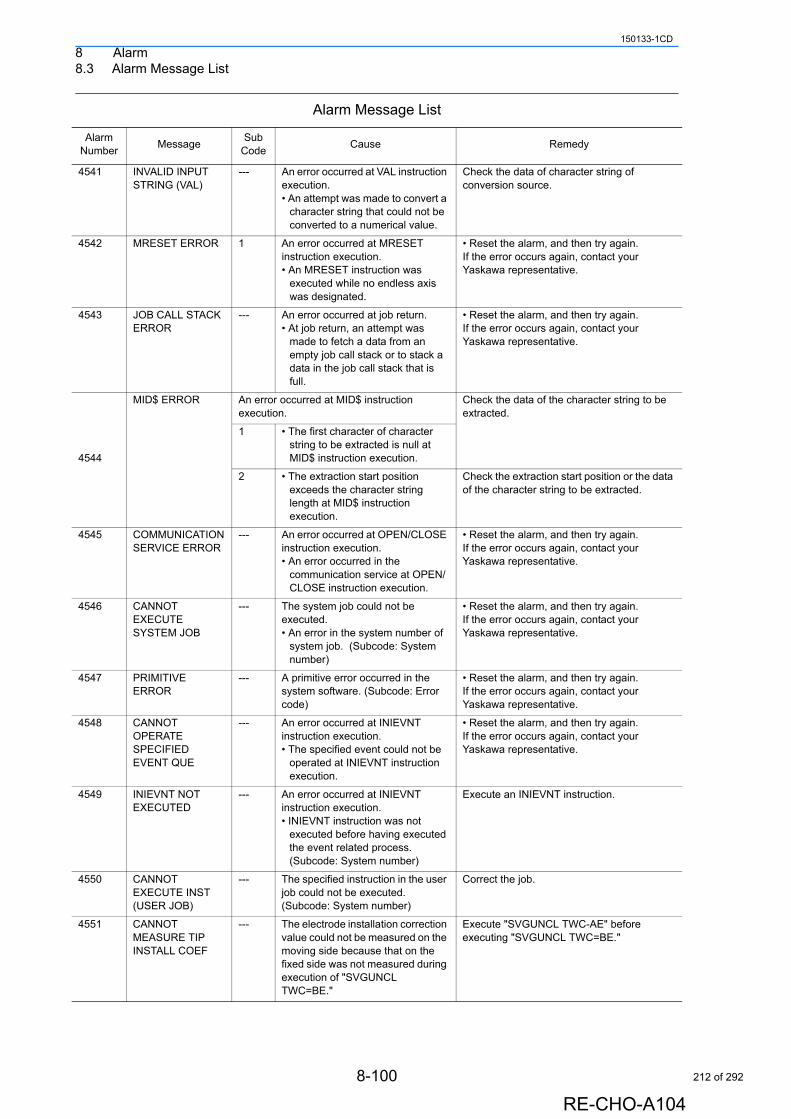
8 Alarm8.3 Alarm Message List
150133-1CD
4541 INVALID INPUT STRING (VAL)
--- An error occurred at VAL instruction execution.• An attempt was made to convert a
character string that could not be converted to a numerical value.
Check the data of character string of conversion source.
4542 MRESET ERROR 1 An error occurred at MRESET instruction execution.• An MRESET instruction was
executed while no endless axis was designated.
• Reset the alarm, and then try again.If the error occurs again, contact your Yaskawa representative.
4543 JOB CALL STACK ERROR
--- An error occurred at job return.• At job return, an attempt was
made to fetch a data from an empty job call stack or to stack a data in the job call stack that is full.
• Reset the alarm, and then try again.If the error occurs again, contact your Yaskawa representative.
4544
MID$ ERROR An error occurred at MID$ instruction execution.
Check the data of the character string to be extracted.
1 • The first character of character string to be extracted is null at MID$ instruction execution.
2 • The extraction start position exceeds the character string length at MID$ instruction execution.
Check the extraction start position or the data of the character string to be extracted.
4545 COMMUNICATION SERVICE ERROR
--- An error occurred at OPEN/CLOSE instruction execution.• An error occurred in the
communication service at OPEN/CLOSE instruction execution.
• Reset the alarm, and then try again.If the error occurs again, contact your Yaskawa representative.
4546 CANNOT EXECUTE SYSTEM JOB
--- The system job could not be executed.• An error in the system number of
system job. (Subcode: System number)
• Reset the alarm, and then try again.If the error occurs again, contact your Yaskawa representative.
4547 PRIMITIVE ERROR
--- A primitive error occurred in the system software. (Subcode: Error code)
• Reset the alarm, and then try again.If the error occurs again, contact your Yaskawa representative.
4548 CANNOT OPERATE SPECIFIED EVENT QUE
--- An error occurred at INIEVNT instruction execution.• The specified event could not be
operated at INIEVNT instruction execution.
• Reset the alarm, and then try again.If the error occurs again, contact your Yaskawa representative.
4549 INIEVNT NOT EXECUTED
--- An error occurred at INIEVNT instruction execution.• INIEVNT instruction was not
executed before having executed the event related process. (Subcode: System number)
Execute an INIEVNT instruction.
4550 CANNOT EXECUTE INST (USER JOB)
--- The specified instruction in the user job could not be executed. (Subcode: System number)
Correct the job.
4551 CANNOT MEASURE TIP INSTALL COEF
--- The electrode installation correction value could not be measured on the moving side because that on the fixed side was not measured during execution of "SVGUNCL TWC=BE."
Execute "SVGUNCL TWC-AE" before executing "SVGUNCL TWC=BE."
Alarm Message List
Alarm Number
MessageSub
CodeCause Remedy
8-100
RE-CHO-A104
212 of 292
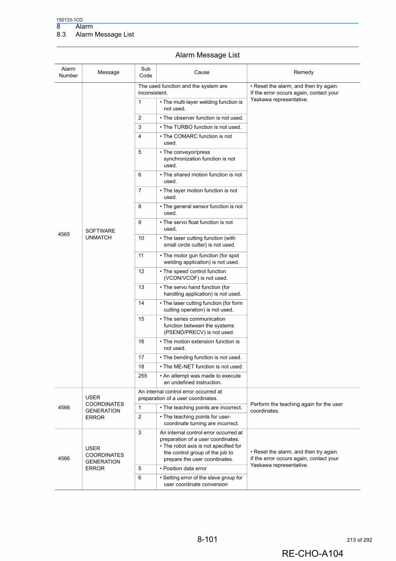
8 Alarm8.3 Alarm Message List
150133-1CD
4565SOFTWARE UNMATCH
The used function and the system are inconsistent.
• Reset the alarm, and then try again.If the error occurs again, contact your Yaskawa representative.1 • The multi-layer welding function is
not used.
2 • The observer function is not used.
3 • The TURBO function is not used.
4 • The COMARC function is not used.
5 • The conveyor/press synchronization function is not used.
6 • The shared motion function is not used.
7 • The layer motion function is not used.
8 • The general sensor function is not used.
9 • The servo float function is not used.
10 • The laser cutting function (with small circle cutter) is not used.
11 • The motor gun function (for spot welding application) is not used.
12 • The speed control function (VCON/VCOF) is not used.
13 • The servo hand function (for handling application) is not used.
14 • The laser cutting function (for form cutting operation) is not used.
15 • The series communication function between the systems (PSEND/PRECV) is not used.
16 • The motion extension function is not used.
17 • The bending function is not used.
18 • The ME-NET function is not used.
255 • An attempt was made to execute an undefined instruction.
4566
USER COORDINATES GENERATION ERROR
An internal control error occurred at preparation of a user coordinates.
Perform the teaching again for the user coordinates.
1 • The teaching points are incorrect.
2 • The teaching points for user-coordinate turning are incorrect.
4566
USER COORDINATES GENERATION ERROR
3 An internal control error occurred at preparation of a user coordinates.• The robot axis is not specified for
the control group of the job to prepare the user coordinates.
• Reset the alarm, and then try again. If the error occurs again, contact your Yaskawa representative.
5 • Position data error
6 • Setting error of the slave group for user coordinate conversion
Alarm Message List
Alarm Number
MessageSub
CodeCause Remedy
8-101
RE-CHO-A104
213 of 292
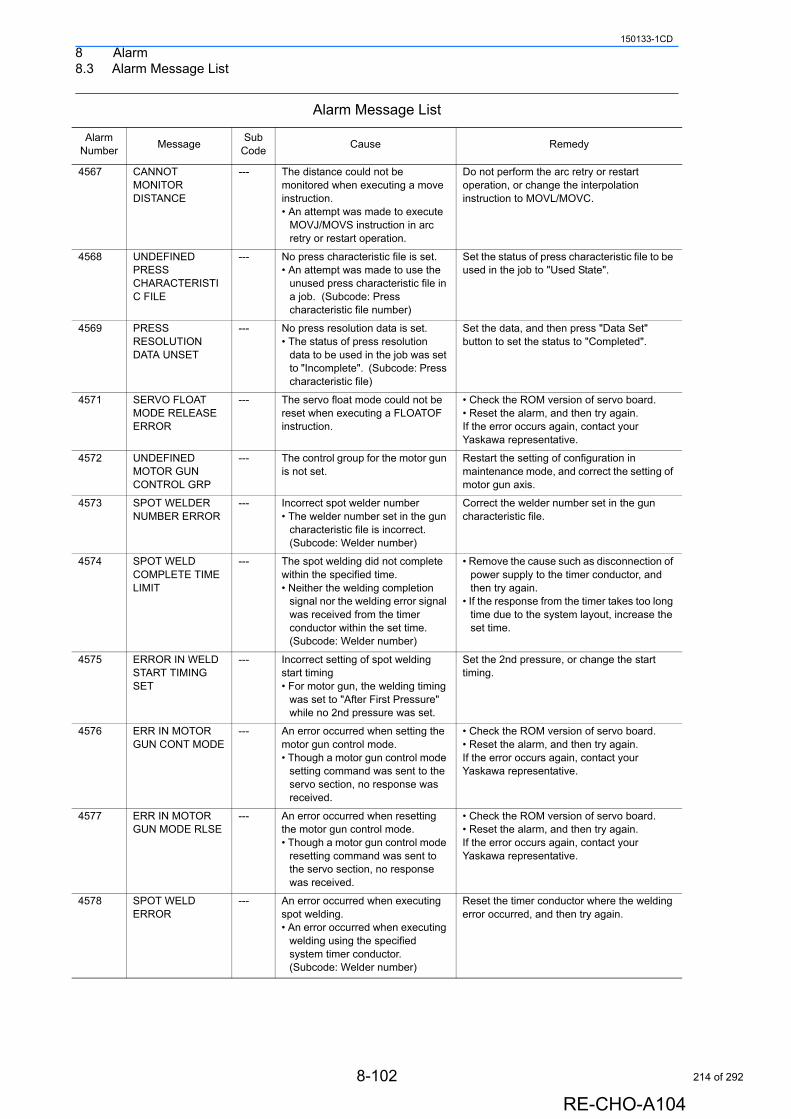
8 Alarm8.3 Alarm Message List
150133-1CD
4567 CANNOT MONITOR DISTANCE
--- The distance could not be monitored when executing a move instruction.• An attempt was made to execute
MOVJ/MOVS instruction in arc retry or restart operation.
Do not perform the arc retry or restart operation, or change the interpolation instruction to MOVL/MOVC.
4568 UNDEFINED PRESS CHARACTERISTIC FILE
--- No press characteristic file is set.• An attempt was made to use the
unused press characteristic file in a job. (Subcode: Press characteristic file number)
Set the status of press characteristic file to be used in the job to "Used State".
4569 PRESS RESOLUTION DATA UNSET
--- No press resolution data is set.• The status of press resolution
data to be used in the job was set to "Incomplete". (Subcode: Press characteristic file)
Set the data, and then press "Data Set" button to set the status to "Completed".
4571 SERVO FLOAT MODE RELEASE ERROR
--- The servo float mode could not be reset when executing a FLOATOF instruction.
• Check the ROM version of servo board.• Reset the alarm, and then try again.If the error occurs again, contact your Yaskawa representative.
4572 UNDEFINED MOTOR GUN CONTROL GRP
--- The control group for the motor gun is not set.
Restart the setting of configuration in maintenance mode, and correct the setting of motor gun axis.
4573 SPOT WELDER NUMBER ERROR
--- Incorrect spot welder number• The welder number set in the gun
characteristic file is incorrect. (Subcode: Welder number)
Correct the welder number set in the gun characteristic file.
4574 SPOT WELD COMPLETE TIME LIMIT
--- The spot welding did not complete within the specified time.• Neither the welding completion
signal nor the welding error signal was received from the timer conductor within the set time. (Subcode: Welder number)
• Remove the cause such as disconnection of power supply to the timer conductor, and then try again.
• If the response from the timer takes too long time due to the system layout, increase the set time.
4575 ERROR IN WELD START TIMING SET
--- Incorrect setting of spot welding start timing• For motor gun, the welding timing
was set to "After First Pressure" while no 2nd pressure was set.
Set the 2nd pressure, or change the start timing.
4576 ERR IN MOTOR GUN CONT MODE
--- An error occurred when setting the motor gun control mode.• Though a motor gun control mode
setting command was sent to the servo section, no response was received.
• Check the ROM version of servo board.• Reset the alarm, and then try again.If the error occurs again, contact your Yaskawa representative.
4577 ERR IN MOTOR GUN MODE RLSE
--- An error occurred when resetting the motor gun control mode.• Though a motor gun control mode
resetting command was sent to the servo section, no response was received.
• Check the ROM version of servo board.• Reset the alarm, and then try again.If the error occurs again, contact your Yaskawa representative.
4578 SPOT WELD ERROR
--- An error occurred when executing spot welding.• An error occurred when executing
welding using the specified system timer conductor. (Subcode: Welder number)
Reset the timer conductor where the welding error occurred, and then try again.
Alarm Message List
Alarm Number
MessageSub
CodeCause Remedy
8-102
RE-CHO-A104
214 of 292
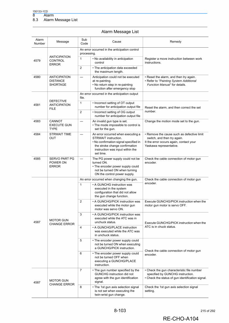
8 Alarm8.3 Alarm Message List
150133-1CD
4579ANTICIPATION CONTROL ERROR
An error occurred in the anticipation control processing.
Register a move instruction between work instructions.
1 • No availability in anticipation control
2 • The anticipation data exceeded the maximum length.
4580 ANTICIPATION DISTANCE SHORTAGE
--- Anticipation could not be executed at re-painting.• No return step in re-painting
function after emergency stop
• Reset the alarm, and then try again.• Refer to "Painting System Additional
Function Manual" for details.
4581DEFECTIVE ANTICIPATION FILE
An error occurred in the anticipation output file.
1 • Incorrect setting of OT output number for anticipation output file Reset the alarm, and then correct the set
number.2 • Incorrect setting of OG output number for anticipation output file
4583 CANNOT EXECUTE GUN TYPE
--- An invalid gun type is set.• The mode impossible to control is
set for the gun.
Change the motion mode set to the gun.
4584 STRWAIT TIME OUT
--- An error occurred when executing a STRWAIT instruction.• No confirmation signal specified in
the stroke change confirmation instruction was input within the set time.
• Remove the cause such as defective limit switch, and then try again.
It the error occurs again, contact your Yaskawa representative.
4585 SERVO PART PG POWER ON ERROR
--- The PG power supply could not be turned ON.• The encoder power supply could
not be turned ON when turning ON the control power supply.
Check the cable connection of motor gun encoder.
4587MOTOR GUN CHANGE ERROR
An error occurred when changing the gun. Check the cable connection of motor gun encoder.1 • A GUNCHG instruction was
executed in the system configuration that did not allow the gun change function.
2 • A GUNCHG/PICK instruction was executed while the motor gun motor was servo ON.
Execute GUNCHG/PICK instruction when the motor gun motor is servo OFF.
3 • A GUNCHG/PICK instruction was executed while the ATC was in unchuck status. Execute GUNCHG/PICK instruction when the
ATC is in chuck status.4 • A GUNCHG/PLACE instruction was executed while the ATC was in unchuck status.
5 • The encoder power supply could not be turned ON when executing a GUNCHG/PICK instruction.
Check the cable connection of motor gun encoder.6 • The encoder power supply could
not be turned OFF when executing a GUNCHG/PLACE instruction.
4587MOTOR GUN CHANGE ERROR
7 • The gun number specified by the GUNCHG instruction did not agree with the gun identification signal.
• Check the gun characteristic file number specified by GUNCHG instruction.
• Check the status of gun identification signal.
8 • The 1st gun axis selection signal is not set when executing the twin-wrist gun change.
Check the 1st gun axis selection signal setting.
Alarm Message List
Alarm Number
MessageSub
CodeCause Remedy
8-103
RE-CHO-A104
215 of 292
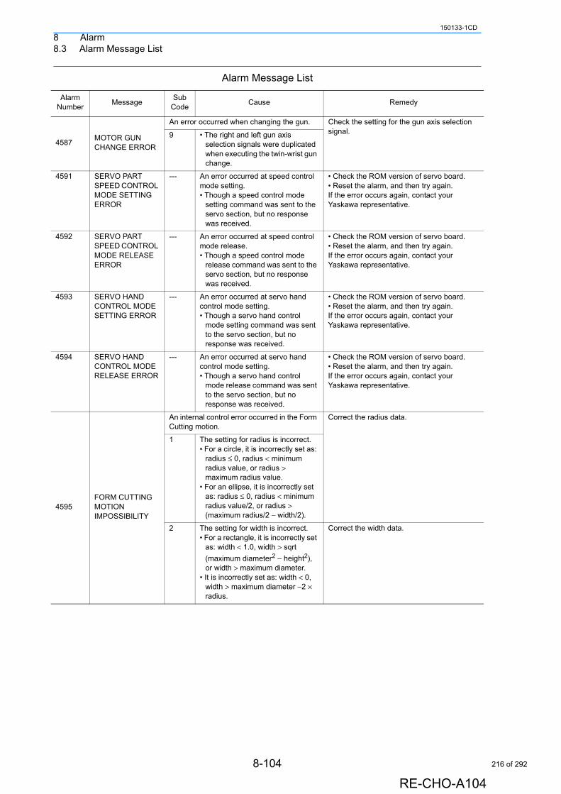
8 Alarm8.3 Alarm Message List
150133-1CD
4587MOTOR GUN CHANGE ERROR
An error occurred when changing the gun. Check the setting for the gun axis selection signal.9 • The right and left gun axis
selection signals were duplicated when executing the twin-wrist gun change.
4591 SERVO PART SPEED CONTROL MODE SETTING ERROR
--- An error occurred at speed control mode setting.• Though a speed control mode
setting command was sent to the servo section, but no response was received.
• Check the ROM version of servo board.• Reset the alarm, and then try again.If the error occurs again, contact your Yaskawa representative.
4592 SERVO PART SPEED CONTROL MODE RELEASE ERROR
--- An error occurred at speed control mode release.• Though a speed control mode
release command was sent to the servo section, but no response was received.
• Check the ROM version of servo board.• Reset the alarm, and then try again.If the error occurs again, contact your Yaskawa representative.
4593 SERVO HAND CONTROL MODE SETTING ERROR
--- An error occurred at servo hand control mode setting.• Though a servo hand control
mode setting command was sent to the servo section, but no response was received.
• Check the ROM version of servo board.• Reset the alarm, and then try again.If the error occurs again, contact your Yaskawa representative.
4594 SERVO HAND CONTROL MODE RELEASE ERROR
--- An error occurred at servo hand control mode setting.• Though a servo hand control
mode release command was sent to the servo section, but no response was received.
• Check the ROM version of servo board.• Reset the alarm, and then try again.If the error occurs again, contact your Yaskawa representative.
4595FORM CUTTING MOTION IMPOSSIBILITY
An internal control error occurred in the Form Cutting motion.
Correct the radius data.
1 The setting for radius is incorrect.• For a circle, it is incorrectly set as:
radius ≤ 0, radius < minimum radius value, or radius > maximum radius value.
• For an ellipse, it is incorrectly set as: radius ≤ 0, radius < minimum radius value/2, or radius > (maximum radius/2 − width/2).
2 The setting for width is incorrect.• For a rectangle, it is incorrectly set
as: width < 1.0, width > sqrt
(maximum diameter2 − height2), or width > maximum diameter.
• It is incorrectly set as: width < 0, width > maximum diameter −2 × radius.
Correct the width data.
Alarm Message List
Alarm Number
MessageSub
CodeCause Remedy
8-104
RE-CHO-A104
216 of 292
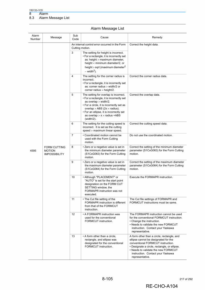
8 Alarm8.3 Alarm Message List
150133-1CD
4595FORM CUTTING MOTION IMPOSSIBILITY
An internal control error occurred in the Form Cutting motion.
Correct the height data.
3 The setting for height is incorrect. • For a rectangle, it is incorrectly set
as: height > maximum diameter, height < minimum diameter/2, or
height > sqrt (maximum diameter2
− width2).
4 The setting for the corner radius is incorrect.• For a rectangle, it is incorrectly set
as: corner radius > width/2 or corner radius > height/2.
Correct the corner radius data.
5 The setting for overlap is incorrect. • For a rectangle, it is incorrectly set
as overlap > width/2. • For a circle, it is incorrectly set as
overlap > ABS (2π × radius).• For an ellipse, it is incorrectly set
as overlap > π × radius +ABS (width/2).
Correct the overlap data.
6 The setting for the cutting speed is incorrect. It is set as the cutting speed > maximum linear speed.
Correct the cutting speed data.
7 • Coordinated motion cannot be used with the Form Cutting motion.
Do not use the coordinated motion.
8 • Zero or a negative value is set in the minimum diameter parameter (S1CxG063) for the Form Cutting motion.
Correct the setting of the minimum diameter parameter (S1CxG063) for the Form Cutting motion.
9 • Zero or a negative value is set in the maximum diameter parameter (S1CxG064) for the Form Cutting motion.
Correct the setting of the maximum diameter parameter (S1CxG064) for the Form Cutting motion.
10 • Although "PLACEMENT" or "AUTO" is set for the start point designation on the FORM CUT SETTING window, the FORMAPR instruction was not executed.
Execute the FORMAPR instruction.
11 • The Cut file setting of the FORMAPR instruction is different from that of the FORMCUT instruction.
The Cut file settings of FORMAPR and FORMCUT instructions must be same.
12 • A FORMAPR instruction was used for the conventional FORMCUT instruction.
The FORMAPR instruction cannot be used for the conventional FORMCUT instruction. • Change the instruction. • Needs to validate the new FORMCUT
instruction. Contact your Yaskawa representative.
13 • A form other than a circle, rectangle, and ellipse was designated for the conventional FORMCUT instruction.
A form other than a circle, rectangle, and ellipse cannot be designated for the conventional FORMCUT instruction. • Designate a circle, rectangle, or ellipse. • Needs to validate the new FORMCUT
instruction. Contact your Yaskawa representative.
Alarm Message List
Alarm Number
MessageSub
CodeCause Remedy
8-105
RE-CHO-A104
217 of 292
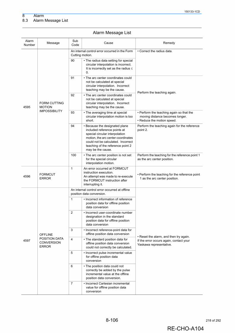
8 Alarm8.3 Alarm Message List
150133-1CD
4595FORM CUTTING MOTION IMPOSSIBILITY
An internal control error occurred in the Form Cutting motion.
• Correct the radius data.
90 • The radius data setting for special circular interpolation is incorrect. It is incorrectly set as the radius ≤ 0.
91 • The arc center coordinates could not be calculated at special circular interpolation. Incorrect teaching may be the cause.
Perform the teaching again.92 • The arc center coordinates could
not be calculated at special circular interpolation. Incorrect teaching may be the cause.
93 • The averaging time at special circular interpolation motion is too short.
• Perform the teaching again so that the moving distance becomes longer.
• Reduce the motion speed.
94 • Because the designated plane included reference points at special circular interpolation motion, the arc center coordinates could not be calculated. Incorrect teaching of the reference point 2 may be the cause.
Perform the teaching again for the reference point 2.
100 • The arc center position is not set for the special circular interpolation motion.
Perform the teaching for the reference point 1 as the arc center position.
4596FORMCUT ERROR
1 An error occurred at FORMCUT instruction execution.An attempt was made to re-execute the FORMCUT instruction after interrupting it.
• Perform the teaching for the reference point 1 as the arc center position.
4597
OFFLINE POSITION DATA CONVERSION ERROR
An internal control error occurred at offline position data conversion.
• Reset the alarm, and then try again. If the error occurs again, contact your Yaskawa representative.
1 • Incorrect information of reference position data for offline position data conversion
2 • Incorrect user-coordinate number designation in the standard position data for offline position data conversion
3 • Incorrect reference-point data for offline position data conversion
4 • The standard position data for offline position data conversion could not correctly be calculated.
5 • Incorrect pulse incremental value for offline position data conversion
6 • The position data could not correctly be added by the pulse incremental value at the offline position data conversion.
7 • Incorrect Cartesian incremental value for offline position data conversion
Alarm Message List
Alarm Number
MessageSub
CodeCause Remedy
8-106
RE-CHO-A104
218 of 292
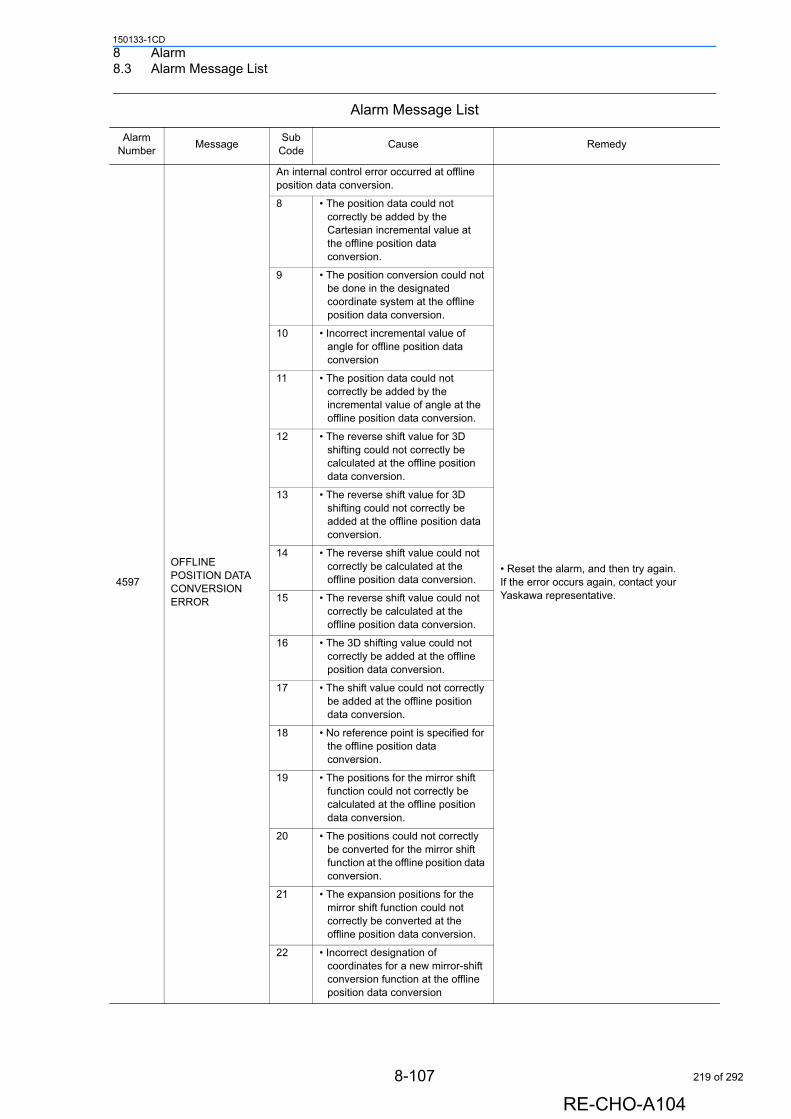
8 Alarm8.3 Alarm Message List
150133-1CD
4597
OFFLINE POSITION DATA CONVERSION ERROR
An internal control error occurred at offline position data conversion.
• Reset the alarm, and then try again. If the error occurs again, contact your Yaskawa representative.
8 • The position data could not correctly be added by the Cartesian incremental value at the offline position data conversion.
9 • The position conversion could not be done in the designated coordinate system at the offline position data conversion.
10 • Incorrect incremental value of angle for offline position data conversion
11 • The position data could not correctly be added by the incremental value of angle at the offline position data conversion.
12 • The reverse shift value for 3D shifting could not correctly be calculated at the offline position data conversion.
13 • The reverse shift value for 3D shifting could not correctly be added at the offline position data conversion.
14 • The reverse shift value could not correctly be calculated at the offline position data conversion.
15 • The reverse shift value could not correctly be calculated at the offline position data conversion.
16 • The 3D shifting value could not correctly be added at the offline position data conversion.
17 • The shift value could not correctly be added at the offline position data conversion.
18 • No reference point is specified for the offline position data conversion.
19 • The positions for the mirror shift function could not correctly be calculated at the offline position data conversion.
20 • The positions could not correctly be converted for the mirror shift function at the offline position data conversion.
21 • The expansion positions for the mirror shift function could not correctly be converted at the offline position data conversion.
22 • Incorrect designation of coordinates for a new mirror-shift conversion function at the offline position data conversion
Alarm Message List
Alarm Number
MessageSub
CodeCause Remedy
8-107
RE-CHO-A104
219 of 292

8 Alarm8.3 Alarm Message List
150133-1CD
4599 SERVO COMMAND ERROR
0 An abnormal response was returned from the servo control section.The servo control processing has not completed.
• Reset the alarm, and then try again. • Turn the power OFF then back ON. If the error occurs again, contact your Yaskawa representative.
4601 UNDEFINED GUN COND FILE
--- The motor gun characteristic file is not set. (Subcode: Motor gun characteristic file number)
Complete the settings for the motor gun characteristic file.
4603 WIRE STICKING --- Wire stick occurred at spot welding.• Wire stick was detected at the
welder. (Subcode: Welder number)
Remove the cause of wire stick.
4604 DESIGNATED AXIS HOME POSITION CORRECTION DATA NON-EXISTING
--- No home position correction data of specified axis
• Reset the alarm, and then try again.If the error occurs again, contact your Yaskawa representative.
4605 SETTOOL ERROR --- An error occurred when executing a SETTOOL instruction.• The difference between the
current tool constant and a new set value exceeded the allowable range (parameter set value).
• Check if the tag set value is correct.• Check if the parameter is set correctly.
4606 GLOBAL VARIABLE AREA OVERFLOW
--- The memory area of global variable exceeded the limit value.• An error occurred in the value of
parameter that defines the number of global (user) variables.
Correct the number of global (user) variables to be used, or correct the parameter value.
4607
MACRO COMMAND EXECUTION ERROR
An error occurred when executing a macro instruction.
Correct the registration of interrupt macro job.1 • The execution macro job is not set.
2 • The interrupt macro job is not set.
3 • An attempt was made to start the job that could not be started by the macro instruction.
Correct the macro job.
5 • An error occurred in the operation process of job call stack when the execution of macro instruction was cancelled.
• Reset the alarm, and then try again.• Turn the power OFF then back ON.If the error occurs again, contact your Yaskawa representative.
6 • Incorrect macro number
4608JOB ARGUMENT GET ERROR
An error occurred when executing a GETARG instruction.
Correct the job.
1 • The job argument is not set.
2 • No number of the specified job argument
3 • The data types of job argument disagreed.
Alarm Message List
Alarm Number
MessageSub
CodeCause Remedy
8-108
RE-CHO-A104
220 of 292
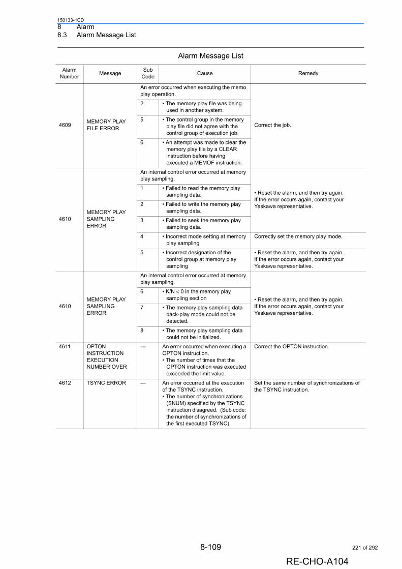
8 Alarm8.3 Alarm Message List
150133-1CD
4609MEMORY PLAY FILE ERROR
An error occurred when executing the memo play operation.
Correct the job.
2 • The memory play file was being used in another system.
5 • The control group in the memory play file did not agree with the control group of execution job.
6 • An attempt was made to clear the memory play file by a CLEAR instruction before having executed a MEMOF instruction.
4610MEMORY PLAY SAMPLING ERROR
An internal control error occurred at memory play sampling.
• Reset the alarm, and then try again. If the error occurs again, contact your Yaskawa representative.
1 • Failed to read the memory play sampling data.
2 • Failed to write the memory play sampling data.
3 • Failed to seek the memory play sampling data.
4 • Incorrect mode setting at memory play sampling
Correctly set the memory play mode.
5 • Incorrect designation of the control group at memory play sampling
• Reset the alarm, and then try again. If the error occurs again, contact your Yaskawa representative.
4610MEMORY PLAY SAMPLING ERROR
An internal control error occurred at memory play sampling.
• Reset the alarm, and then try again. If the error occurs again, contact your Yaskawa representative.
6 • K/N < 0 in the memory play sampling section
7 • The memory play sampling data back-play mode could not be detected.
8 • The memory play sampling data could not be initialized.
4611 OPTON INSTRUCTION EXECUTION NUMBER OVER
--- An error occurred when executing a OPTON instruction.• The number of times that the
OPTON instruction was executed exceeded the limit value.
Correct the OPTON instruction.
4612 TSYNC ERROR --- An error occurred at the execution of the TSYNC instruction.• The number of synchronizations
(SNUM) specified by the TSYNC instruction disagreed. (Sub code: the number of synchronizations of the first executed TSYNC)
Set the same number of synchronizations of the TSYNC instruction.
Alarm Message List
Alarm Number
MessageSub
CodeCause Remedy
8-109
RE-CHO-A104
221 of 292
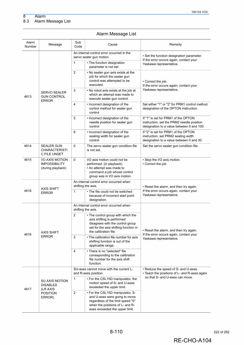
8 Alarm8.3 Alarm Message List
150133-1CD
4613SERVO SEALER GUN CONTROL ERROR
An internal control error occurred in the servo sealer gun motion. • Set the function designation parameter.
If the error occurs again, contact your Yaskawa representative.1 • The function designation
parameter is not set.
2 • No sealer gun axis exists at the job for which the sealer gun control was attempted to be executed.
• Correct the job.If the error occurs again, contact your Yaskawa representative.3 • No robot axis exists at the job at
which an attempt was made to execute sealer gun control.
4 • Incorrect designation of the control method for sealer gun control
Set either "1" or "2" for PRM1 control method designation of the OPTON instruction.
5 • Incorrect designation of the needle position for sealer gun control
If "1" is set for PRM1 of the OPTON instruction, set the PRM2 needle position designation to a value between 0 and 100.
6 • Incorrect designation of the sealing width for sealer gun control
If "2" is set for PRM1 of the OPTON instruction, set PRM2 sealing width designation to a value between 0 and 30.
4614 SEALER GUN CHARACTERISTIC FILE UNSET
0 The servo sealer gun condition file is not set.
Set the servo sealer gun condition file.
4615 I/O AXIS MOTION IMPOSSIBILITY (during playback)
0 I/O axis motion could not be performed. (in playback)• An attempt was made to
command a job whose control group was in I/O axis motion.
• Stop the I/O axis motion. • Correct the job.
4616AXIS SHIFT ERROR
An internal control error occurred when shifting the axis. • Reset the alarm, and then try again.
If the error occurs again, contact your Yaskawa representative.
1 • The file could not be switched because of incorrect start point designation.
4616AXIS SHIFT ERROR
An internal control error occurred when shifting the axis.
• Reset the alarm, and then try again. If the error occurs again, contact your Yaskawa representative.
2 • The control group with which the axis shifting is performed disagrees with the control group set for the axis shifting function in the calibration file.
3 • The calibration file number for axis shifting function is out of the applicable range.
4 • There is no "selected" file corresponding to the calibration file number for the axis shift function.
4617
SU AXIS MOTION DISABLED (LR AXIS POSITION ERROR)
SU-axes cannot move with the current L- and R-axes position.
• Reduce the speed of S- and U-axes. • Teach the positions of L- and R-axes again
so that S- and U-axes can move.1 • For the CSL15D manipulator, the motion speed of S- and U-axes exceeded the upper limit.
2 • For the CSL15D manipulator, S- and U-axes were going to move regardless of the limit speed "0" when the positions of L- and R-axes exceeded the upper limit.
Alarm Message List
Alarm Number
MessageSub
CodeCause Remedy
8-110
RE-CHO-A104
222 of 292
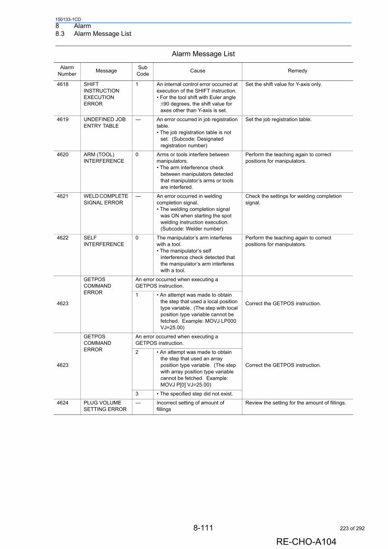
8 Alarm8.3 Alarm Message List
150133-1CD
4618 SHIFT INSTRUCTION EXECUTION ERROR
1 An internal control error occurred at execution of the SHIFT instruction.• For the tool shift with Euler angle
±90 degrees, the shift value for axes other than Y-axis is set.
Set the shift value for Y-axis only.
4619 UNDEFINED JOB ENTRY TABLE
--- An error occurred in job registration table.• The job registration table is not
set. (Subcode: Designated registration number)
Set the job registration table.
4620 ARM (TOOL) INTERFERENCE
0 Arms or tools interfere between manipulators.• The arm interference check
between manipulators detected that manipulator’s arms or tools are interfered.
Perform the teaching again to correct positions for manipulators.
4621 WELD COMPLETE SIGNAL ERROR
--- An error occurred in welding completion signal.• The welding completion signal
was ON when starting the spot welding instruction execution. (Subcode: Welder number)
Check the settings for welding completion signal.
4622 SELF INTERFERENCE
0 The manipulator’s arm interferes with a tool.• The manipulator’s self
interference check detected that the manipulator’s arm interferes with a tool.
Perform the teaching again to correct positions for manipulators.
4623
GETPOS COMMAND ERROR
An error occurred when executing a GETPOS instruction.
Correct the GETPOS instruction.
1 • An attempt was made to obtain the step that used a local position type variable. (The step with local position type variable cannot be fetched. Example: MOVJ LP000 VJ=25.00)
4623
GETPOS COMMAND ERROR
An error occurred when executing a GETPOS instruction.
Correct the GETPOS instruction.
2 • An attempt was made to obtain the step that used an array position type variable. (The step with array position type variable cannot be fetched. Example: MOVJ P[0] VJ=25.00)
3 • The specified step did not exist.
4624 PLUG VOLUME SETTING ERROR
--- Incorrect setting of amount of fillings
Review the setting for the amount of fillings.
Alarm Message List
Alarm Number
MessageSub
CodeCause Remedy
8-111
RE-CHO-A104
223 of 292
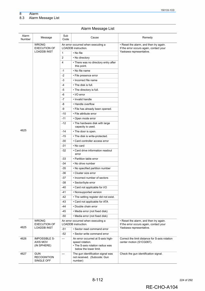
8 Alarm8.3 Alarm Message List
150133-1CD
4625
WRONG EXECUTION OF LOADDB INST
An error occurred when executing a LOADDB instruction.
• Reset the alarm, and then try again.If the error occurs again, contact your Yaskawa representative.1 • No file
2 • No directory
4 • There was no directory entry after this point.
-1 • No file name
-2 • File presence error
-3 • Incorrect file name
-4 • The disk is full.
-5 • The directory is full.
-6 • I/O error
-7 • Invalid handle
-8 • Handle overflow
-9 • File has already been opened.
-10 • File attribute error
-11 • Open mode error
-12 • The hardware disk with large capacity is used.
-14 • The door is open.
-15 • The disk is write-protected.
-30 • Card controller access error
-31 • No card
-32 • Card drive information readout error
-33 • Partition table error
-34 • No drive number
-35 • No specified partition number
-36 • Cluster size error
-37 • Incorrect number of sectors
-38 • Sector/byte error
-40 • Card not applicable for I/O
-41 • Nonsupported version
-42 • The setting register did not exist.
-43 • Card not applicable for ATA
-44 • Double chain error
-45 • Media error (not fixed disk)
-50 • Media error (not fixed disk)
4625
WRONG EXECUTION OF LOADDB INST
An error occurred when executing a LOADDB instruction.
• Reset the alarm, and then try again.If the error occurs again, contact your Yaskawa representative.-51 • Sector read command error
-52 • Sector write command error
4626 IMPOSSIBLE S-AXIS MOV (IN SPHERE)
--- An error occurred at S-axis high-speed rotation.• The S-axis rotation radius was
below the lower limit.
Correct the limit distance for S-axis rotation center motion (S1CG067).
4627 GUN RECOGNITION SINGLE OFF
--- The gun identification signal was not received. (Subcode: Gun number)
Check the gun identification signal.
Alarm Message List
Alarm Number
MessageSub
CodeCause Remedy
8-112
RE-CHO-A104
224 of 292
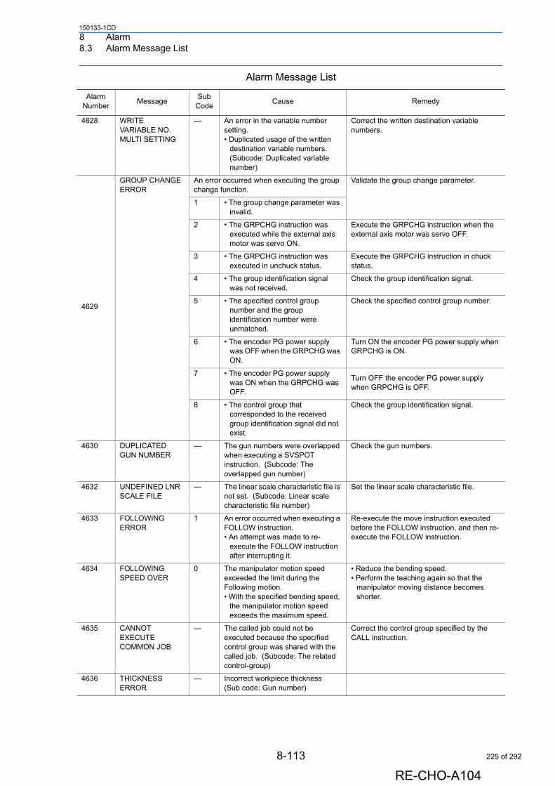
8 Alarm8.3 Alarm Message List
150133-1CD
4628 WRITE VARIABLE NO. MULTI SETTING
--- An error in the variable number setting.• Duplicated usage of the written
destination variable numbers. (Subcode: Duplicated variable number)
Correct the written destination variable numbers.
4629
GROUP CHANGE ERROR
An error occurred when executing the group change function.
Validate the group change parameter.
1 • The group change parameter was invalid.
2 • The GRPCHG instruction was executed while the external axis motor was servo ON.
Execute the GRPCHG instruction when the external axis motor was servo OFF.
3 • The GRPCHG instruction was executed in unchuck status.
Execute the GRPCHG instruction in chuck status.
4 • The group identification signal was not received.
Check the group identification signal.
5 • The specified control group number and the group identification number were unmatched.
Check the specified control group number.
6 • The encoder PG power supply was OFF when the GRPCHG was ON.
Turn ON the encoder PG power supply when GRPCHG is ON.
7 • The encoder PG power supply was ON when the GRPCHG was OFF.
Turn OFF the encoder PG power supply when GRPCHG is OFF.
8 • The control group that corresponded to the received group identification signal did not exist.
Check the group identification signal.
4630 DUPLICATED GUN NUMBER
--- The gun numbers were overlapped when executing a SVSPOT instruction. (Subcode: The overlapped gun number)
Check the gun numbers.
4632 UNDEFINED LNR SCALE FILE
--- The linear scale characteristic file is not set. (Subcode: Linear scale characteristic file number)
Set the linear scale characteristic file.
4633 FOLLOWING ERROR
1 An error occurred when executing a FOLLOW instruction.• An attempt was made to re-
execute the FOLLOW instruction after interrupting it.
Re-execute the move instruction executed before the FOLLOW instruction, and then re-execute the FOLLOW instruction.
4634 FOLLOWING SPEED OVER
0 The manipulator motion speed exceeded the limit during the Following motion.• With the specified bending speed,
the manipulator motion speed exceeds the maximum speed.
• Reduce the bending speed. • Perform the teaching again so that the
manipulator moving distance becomes shorter.
4635 CANNOT EXECUTE COMMON JOB
--- The called job could not be executed because the specified control group was shared with the called job. (Subcode: The related control-group)
Correct the control group specified by the CALL instruction.
4636 THICKNESS ERROR
--- Incorrect workpiece thickness(Sub code: Gun number)
Alarm Message List
Alarm Number
MessageSub
CodeCause Remedy
8-113
RE-CHO-A104
225 of 292
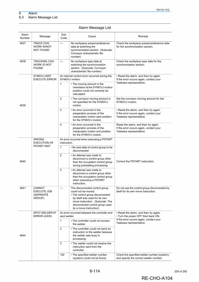
8 Alarm8.3 Alarm Message List
150133-1CD
4637 TRACK CHG WORK IN/NOT NOT FOUND
--- No workpiece presence/absence data at switching the synchronization section. (Subcode: Conveyor characteristic file number)
Check the workpiece presence/absence data for the synchronization section.
4638 TRACKING CHG WORK ID NOT FOUND
--- No workpiece type data at switching the synchronization section. (Subcode: Conveyor characteristic file number)
Check the workpiece type data for the synchronization section.
4639
SYMOVJ INST EXECUTE ERROR
An internal control error occurred during the SYMOVJ motion.
• Reset the alarm, and then try again. If the error occurs again, contact your Yaskawa representative.1 • The moving amount in the
orientation at the SYMOVJ motion position could not correctly be calculated.
2 • The conveyor moving amount is not specified for the SYMOVJ motion.
Set the conveyor moving amount for the SYMOVJ motion.
3 • An error occurred in the preparation process of the manipulator motion start position for the SYMOVJ motion.
• Reset the alarm, and then try again. If the error occurs again, contact your Yaskawa representative.
4 • An error occurred in the preparation process of the manipulator motion end position for the SYMOVJ motion.
Reset the alarm, and then try again. If the error occurs again, contact your Yaskawa representative.
4640
WRONG EXECUTION OF PSTART INST
An error occurred when executing a PSTART instruction.
Correct the PSTART instruction.
1 • No axis data of control group to be disconnected
2 • An attempt was made to disconnect a control group other than the occupation control group during prereading processing.
3 • An attempt was made to disconnect a control group other than the occupation control group when executing a PSTART instruction.
4641 CANNOT EXECUTE JOB (SEPARATE GROUP)
--- The disconnected control group could not be moved.• The control group disconnected
by itself was used for its own move instruction. (Subcode: The disconnected control group used by a move instruction)
Do not use the control group disconnected by itself for its own move instruction.
4644
SPOT WELDER I/F ERROR (ASW)
An error occurred between the controller and spot welder.
• Reset the alarm, and then try again.• Turn the power OFF then back ON.If the error occurs again, contact your Yaskawa representative.
1 • The controller could not access the welder.
2 • The controller could not send an instruction to the welder because the welder was busy in processing.
3 • The welder could not receive the instruction sent from the controller.
102 • The specified welder number (system) could not be found.
Check the specified welder number (system), and specify the correct welder number.
Alarm Message List
Alarm Number
MessageSub
CodeCause Remedy
8-114
RE-CHO-A104
226 of 292
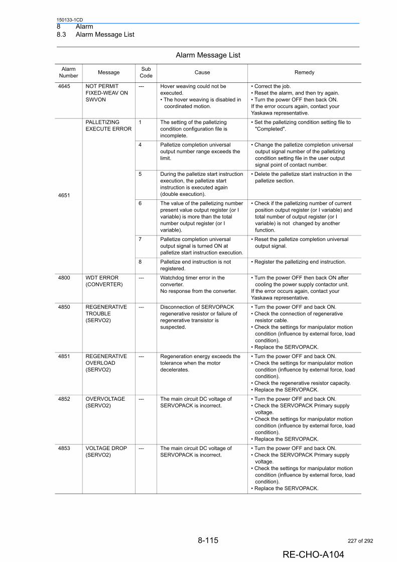
8 Alarm8.3 Alarm Message List
150133-1CD
4645 NOT PERMIT FIXED-WEAV ON SWVON
--- Hover weaving could not be executed.• The hover weaving is disabled in
coordinated motion.
• Correct the job.• Reset the alarm, and then try again.• Turn the power OFF then back ON.If the error occurs again, contact your Yaskawa representative.
4651
PALLETIZING EXECUTE ERROR
1 The setting of the palletizing condition configuration file is incomplete.
• Set the palletizing condition setting file to "Completed".
4 Palletize completion universal output number range exceeds the limit.
• Change the palletize completion universal output signal number of the palletizing condition setting file in the user output signal point of contact number.
5 During the palletize start instruction execution, the palletize start instruction is executed again (double execution).
• Delete the palletize start instruction in the palletize section.
6 The value of the palletizing number present value output register (or I variable) is more than the total number output register (or I variable).
• Check if the palletizing number of current position output register (or I variable) and total number of output register (or I variable) is not changed by another function.
7 Palletize completion universal output signal is turned ON at palletize start instruction execution.
• Reset the palletize completion universal output signal.
8 Palletize end instruction is not registered.
• Register the palletizing end instruction.
4800 WDT ERROR (CONVERTER)
--- Watchdog timer error in the converter. No response from the converter.
• Turn the power OFF then back ON after cooling the power supply contactor unit.
If the error occurs again, contact your Yaskawa representative.
4850 REGENERATIVE TROUBLE (SERVO2)
--- Disconnection of SERVOPACK regenerative resistor or failure of regenerative transistor is suspected.
• Turn the power OFF and back ON.• Check the connection of regenerative
resistor cable.• Check the settings for manipulator motion
condition (influence by external force, load condition).
• Replace the SERVOPACK.
4851 REGENERATIVE OVERLOAD (SERVO2)
--- Regeneration energy exceeds the tolerance when the motor decelerates.
• Turn the power OFF and back ON.• Check the settings for manipulator motion
condition (influence by external force, load condition).
• Check the regenerative resistor capacity.• Replace the SERVOPACK.
4852 OVERVOLTAGE (SERVO2)
--- The main circuit DC voltage of SERVOPACK is incorrect.
• Turn the power OFF and back ON.• Check the SERVOPACK Primary supply
voltage. • Check the settings for manipulator motion
condition (influence by external force, load condition).
• Replace the SERVOPACK.
4853 VOLTAGE DROP (SERVO2)
--- The main circuit DC voltage of SERVOPACK is incorrect.
• Turn the power OFF and back ON.• Check the SERVOPACK Primary supply
voltage. • Check the settings for manipulator motion
condition (influence by external force, load condition).
• Replace the SERVOPACK.
Alarm Message List
Alarm Number
MessageSub
CodeCause Remedy
8-115
RE-CHO-A104
227 of 292
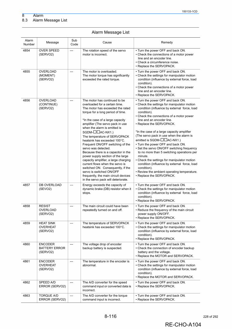
8 Alarm8.3 Alarm Message List
150133-1CD
4854 OVER SPEED (SERVO2)
--- The rotation speed of the servo motor is incorrect.
• Turn the power OFF and back ON.• Check the connections of a motor power
line and an encoder line.• Check a circumference noise.• Replace the SERVOPACK.
4855 OVERLOAD (MOMENT) (SERVO2)
--- The motor is overloaded.The motor torque has significantly exceeded the rated torque.
• Turn the power OFF and back ON.• Check the settings for manipulator motion
condition (influence by external force, load condition).
• Check the connections of a motor power line and an encoder line.
• Replace the SERVOPACK.
4856 OVERLOAD (CONTINUE) (SERVO2)
--- The motor has continued to be overloaded for a certain time.The motor has exceeded the rated torque for a long period of time.
*In the case of a large capacity amplifier (The servo pack in use when the alarm is emitted is
SGDM-AC-NX1.)The temperature of SERVOPACK heatsink has exceeded 100°C.Frequent ON/OFF switching of the servo was detected.Because there is a capacitor in the power supply section of the large capacity amplifier, a large charging current flows when the servo is switched ON. Consequently, if the servo is switched ON/OFF frequently, the main circuit devices in the servo pack will deteriorate.
• Turn the power OFF and back ON.• Check the settings for manipulator motion
condition (influence by external force, load condition).
• Check the connections of a motor power line and an encoder line.
• Replace the SERVOPACK.
*In the case of a large capacity amplifier (The servo pack in use when the alarm is
emitted is SGDM-AC-NX1.)• Turn the power OFF and back ON.• Set the servo ON/OFF switching frequency
to no more than 5 switching operations per minute.
• Check the settings for manipulator motion condition (influence by external force, load condition).
• Review the ambient operating temperature. • Replace the SERVOPACK.
4857 DB OVERLOAD (SEVO2)
--- Energy exceeds the capacity of dynamic brake (DB) resistor when it stops.
• Turn the power OFF and back ON.• Check the settings for manipulator motion
condition (influence by external force, load condition).
• Replace the SERVOPACK.
4858 RESIST OVERLOAD (SERVO2)
--- The main circuit could have been repeatedly turned on and off.
• Turn the power OFF and back ON.• Reduce the frequency of the main circuit
power supply ON/OFF.• Replace the SERVOPACK.
4859 HEAT SINK OVERHEAT (SERVO2)
--- The temperature of SERVOPACK heatsink has exceeded 100°C.
• Turn the power OFF and back ON.• Check the settings for manipulator motion
condition (influence by external force, load condition).
• Replace the SERVOPACK.
4860 ENCODER BATTERY ERROR (SERVO2)
--- The voltage drop of encoder backup battery is suspected.
• Turn the power OFF and back ON.• Check the connection of encoder backup
battery and the voltage.• Replace the MOTOR and SERVOPACK.
4861 ENCODER OVERHEAT (SERVO2)
--- The temperature in the encoder is abnormal.
• Turn the power OFF and back ON.• Check the settings for manipulator motion
condition (influence by external force, load condition).
• Replace the MOTOR and SERVOPACK.
4862 SPEED A/D ERROR (SERVO2)
--- The A/D converter for the speed command input or converted data is incorrect.
• Turn the power OFF and back ON.• Replace the SERVOPACK.
4863 TORQUE A/D ERROR (SERVO2)
--- The A/D converter for the torque command input is incorrect.
• Turn the power OFF and back ON.• Replace the SERVOPACK.
Alarm Message List
Alarm Number
MessageSub
CodeCause Remedy
8-116
RE-CHO-A104
228 of 292

8 Alarm8.3 Alarm Message List
150133-1CD
4864 WRONG MOTOR ROTATION (SERVO2)
--- The detected direction of torque is opposite to that of speed.
• Turn the power OFF and back ON.• Check the connections of a motor power
line and an encoder line.• Replace the MOTOR and SERVOPACK.
4865 POSITION ERROR (SERVO2)
--- The position deviation pulse has exceeded the threshold.
• Turn the power OFF and back ON.• Check the settings for manipulator motion
condition (influence by external force, load condition).
• Check the connections of a motor power line and an encoder line.
• Replace the SERVOPACK.
4866 OPEN PHASE (SERVO2)
--- The voltage of one of three-phase input power supplies to SERVOPACK has dropped.
• Turn the power OFF and back ON.• Check the connection of a three-phase
power supply to SERVOPACK.• Replace the SERVOPACK.
4867 OVERLOAD WARNING (SERVO2)
--- The motor is overloaded. • Turn the power OFF and back ON.• Check the settings for manipulator motion
condition (influence by external force, load condition).
• Check the connections of a motor power line and an encoder line.
• Replace the SERVOPACK.
4868 REGENERATIVE OVERLOAD WARN (SV2)
--- Regeneration energy exceeds the tolerance when the motor decelerates.
• Turn the power OFF and back ON.• Check the settings for manipulator motion
condition (influence by external force, load condition).
• Check the regenerative resistor capacity.
4869 MECHATROLINK DATA SET WARNING(SV2)
--- The MECHATROLINK communication data setting error.
• Turn the power OFF and back ON.• Contact your Yaskawa representative.
4870 MECHATROLINK COMMAND WARNING(SV2)
--- The MECHATROLINK communication command is incorrect.
• Turn the power OFF and back ON.• Contact your Yaskawa representative.
4871 MECHATROLINK2 COMMAND WARNING(SV2)
--- The MECHATROLINK communication is incorrect.
• Turn the power OFF and back ON.• Check the wiring around the
MECHATROLINK communication cable.• Take some action against noises from the
MECHATROLINK communication cable.• Replace the SERVOPACK.
4873 BATTERY WARNING (SERVO2)
--- Warning display indicating the voltage drop of the absolute encoder battery.
• Turn the power OFF and back ON.• Check the battery connection.• Replace the battery.• Replace the SERVOPACK.
4876 POSITION ERROR WARNING (SERVO2)
--- The position deviation pulse has exceeded the tolerance.
• Turn the power OFF and back ON.• Check the settings for manipulator motion
condition (influence by external force, load condition).
• Check the connections of a motor power line.
• Replace the SERVOPACK.
4901 CUBE/AXIS INTERFERENCE 1
--- The manipulator has moved into the specified cube area 1 or the maximum or minimum value of the axis interference 1 was exceeded.
• Check the position in the step (move instruction) where the alarm occurred.
• Change the position in the step (move instruction) where the alarm occurred.
• Check the interference region.
4902 CUBE/AXIS INTERFERENCE 2
--- The manipulator has moved into the specified cube area 2 or the maximum or minimum value of the axis interference 2 was exceeded.
• Check the position in the step (move instruction) where the alarm occurred.
• Change the position in the step (move instruction) where the alarm occurred.
• Check the interference region.
Alarm Message List
Alarm Number
MessageSub
CodeCause Remedy
8-117
RE-CHO-A104
229 of 292
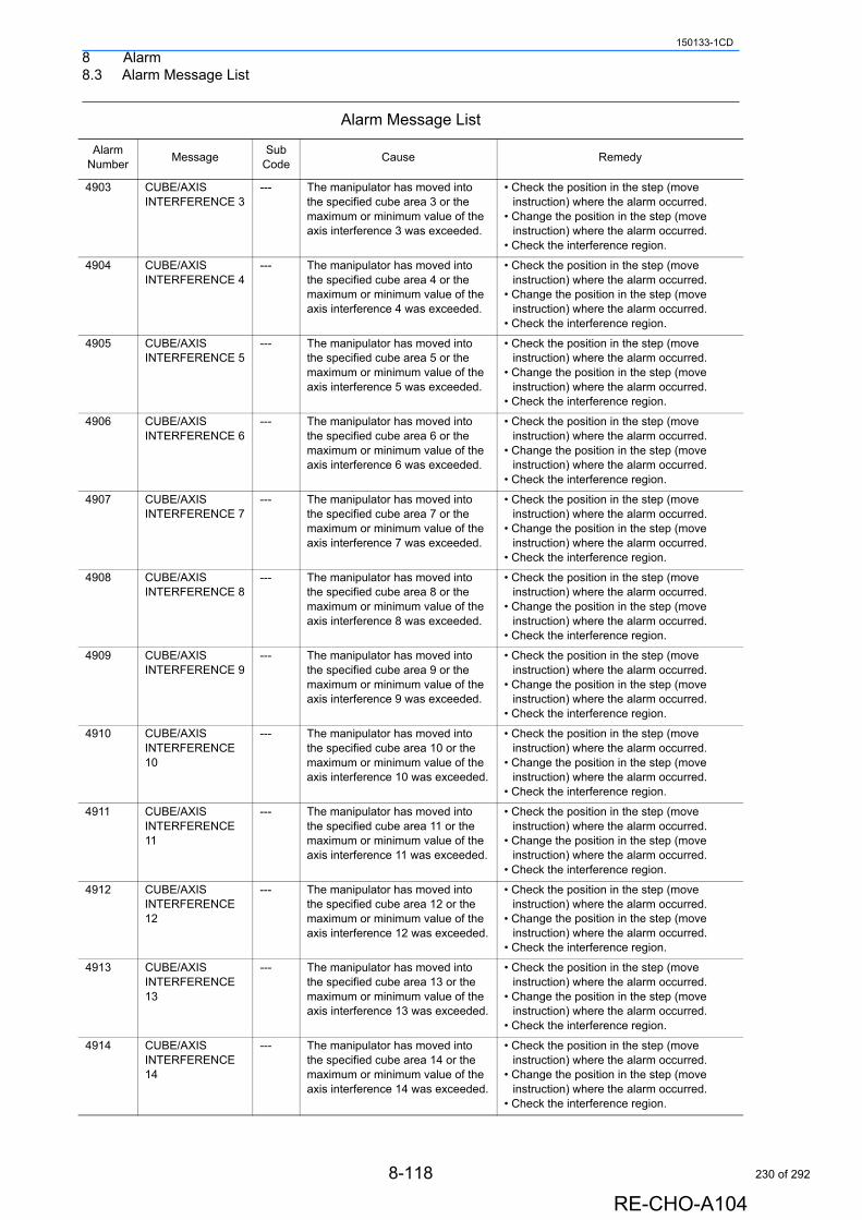
8 Alarm8.3 Alarm Message List
150133-1CD
4903 CUBE/AXIS INTERFERENCE 3
--- The manipulator has moved into the specified cube area 3 or the maximum or minimum value of the axis interference 3 was exceeded.
• Check the position in the step (move instruction) where the alarm occurred.
• Change the position in the step (move instruction) where the alarm occurred.
• Check the interference region.
4904 CUBE/AXIS INTERFERENCE 4
--- The manipulator has moved into the specified cube area 4 or the maximum or minimum value of the axis interference 4 was exceeded.
• Check the position in the step (move instruction) where the alarm occurred.
• Change the position in the step (move instruction) where the alarm occurred.
• Check the interference region.
4905 CUBE/AXIS INTERFERENCE 5
--- The manipulator has moved into the specified cube area 5 or the maximum or minimum value of the axis interference 5 was exceeded.
• Check the position in the step (move instruction) where the alarm occurred.
• Change the position in the step (move instruction) where the alarm occurred.
• Check the interference region.
4906 CUBE/AXIS INTERFERENCE 6
--- The manipulator has moved into the specified cube area 6 or the maximum or minimum value of the axis interference 6 was exceeded.
• Check the position in the step (move instruction) where the alarm occurred.
• Change the position in the step (move instruction) where the alarm occurred.
• Check the interference region.
4907 CUBE/AXIS INTERFERENCE 7
--- The manipulator has moved into the specified cube area 7 or the maximum or minimum value of the axis interference 7 was exceeded.
• Check the position in the step (move instruction) where the alarm occurred.
• Change the position in the step (move instruction) where the alarm occurred.
• Check the interference region.
4908 CUBE/AXIS INTERFERENCE 8
--- The manipulator has moved into the specified cube area 8 or the maximum or minimum value of the axis interference 8 was exceeded.
• Check the position in the step (move instruction) where the alarm occurred.
• Change the position in the step (move instruction) where the alarm occurred.
• Check the interference region.
4909 CUBE/AXIS INTERFERENCE 9
--- The manipulator has moved into the specified cube area 9 or the maximum or minimum value of the axis interference 9 was exceeded.
• Check the position in the step (move instruction) where the alarm occurred.
• Change the position in the step (move instruction) where the alarm occurred.
• Check the interference region.
4910 CUBE/AXIS INTERFERENCE 10
--- The manipulator has moved into the specified cube area 10 or the maximum or minimum value of the axis interference 10 was exceeded.
• Check the position in the step (move instruction) where the alarm occurred.
• Change the position in the step (move instruction) where the alarm occurred.
• Check the interference region.
4911 CUBE/AXIS INTERFERENCE 11
--- The manipulator has moved into the specified cube area 11 or the maximum or minimum value of the axis interference 11 was exceeded.
• Check the position in the step (move instruction) where the alarm occurred.
• Change the position in the step (move instruction) where the alarm occurred.
• Check the interference region.
4912 CUBE/AXIS INTERFERENCE 12
--- The manipulator has moved into the specified cube area 12 or the maximum or minimum value of the axis interference 12 was exceeded.
• Check the position in the step (move instruction) where the alarm occurred.
• Change the position in the step (move instruction) where the alarm occurred.
• Check the interference region.
4913 CUBE/AXIS INTERFERENCE 13
--- The manipulator has moved into the specified cube area 13 or the maximum or minimum value of the axis interference 13 was exceeded.
• Check the position in the step (move instruction) where the alarm occurred.
• Change the position in the step (move instruction) where the alarm occurred.
• Check the interference region.
4914 CUBE/AXIS INTERFERENCE 14
--- The manipulator has moved into the specified cube area 14 or the maximum or minimum value of the axis interference 14 was exceeded.
• Check the position in the step (move instruction) where the alarm occurred.
• Change the position in the step (move instruction) where the alarm occurred.
• Check the interference region.
Alarm Message List
Alarm Number
MessageSub
CodeCause Remedy
8-118
RE-CHO-A104
230 of 292

8 Alarm8.3 Alarm Message List
150133-1CD
4915 CUBE/AXIS INTERFERENCE 15
--- The manipulator has moved into the specified cube area 15 or the maximum or minimum value of the axis interference 15 was exceeded.
• Check the position in the step (move instruction) where the alarm occurred.
• Change the position in the step (move instruction) where the alarm occurred.
• Check the interference region.
4916 CUBE/AXIS INTERFERENCE 16
--- The manipulator has moved into the specified cube area 16 or the maximum or minimum value of the axis interference 16 was exceeded.
• Check the position in the step (move instruction) where the alarm occurred.
• Change the position in the step (move instruction) where the alarm occurred.
• Check the interference region.
4917 CUBE/AXIS INTERFERENCE 17
--- The manipulator has moved into the specified cube area 17 or the maximum or minimum value of the axis interference 17 was exceeded.
• Check the position in the step (move instruction) where the alarm occurred.
• Change the position in the step (move instruction) where the alarm occurred.
• Check the interference region.
4918 CUBE/AXIS INTERFERENCE 18
--- The manipulator has moved into the specified cube area 18 or the maximum or minimum value of the axis interference 18 was exceeded.
• Check the position in the step (move instruction) where the alarm occurred.
• Change the position in the step (move instruction) where the alarm occurred.
• Check the interference region.
4919 CUBE/AXIS INTERFERENCE 19
--- The manipulator has moved into the specified cube area 19 or the maximum or minimum value of the axis interference 19 was exceeded.
• Check the position in the step (move instruction) where the alarm occurred.
• Change the position in the step (move instruction) where the alarm occurred.
• Check the interference region.
4920 CUBE/AXIS INTERFERENCE 20
--- The manipulator has moved into the specified cube area 20 or the maximum or minimum value of the axis interference 20 was exceeded.
• Check the position in the step (move instruction) where the alarm occurred.
• Change the position in the step (move instruction) where the alarm occurred.
• Check the interference region.
4921 CUBE/AXIS INTERFERENCE 21
--- The manipulator has moved into the specified cube area 21 or the maximum or minimum value of the axis interference 21 was exceeded.
• Check the position in the step (move instruction) where the alarm occurred.
• Change the position in the step (move instruction) where the alarm occurred.
• Check the interference region.
4922 CUBE/AXIS INTERFERENCE 22
--- The manipulator has moved into the specified cube area 22 or the maximum or minimum value of the axis interference 22 was exceeded.
• Check the position in the step (move instruction) where the alarm occurred.
• Change the position in the step (move instruction) where the alarm occurred.
• Check the interference region.
4923 CUBE/AXIS INTERFERENCE 23
--- The manipulator has moved into the specified cube area 23 or the maximum or minimum value of the axis interference 23 was exceeded.
• Check the position in the step (move instruction) where the alarm occurred.
• Change the position in the step (move instruction) where the alarm occurred.
• Check the interference region.
4924 CUBE/AXIS INTERFERENCE 24
--- The manipulator has moved into the specified cube area 24 or the maximum or minimum value of the axis interference 24 was exceeded.
• Check the position in the step (move instruction) where the alarm occurred.
• Change the position in the step (move instruction) where the alarm occurred.
• Check the interference region.
Alarm Message List
Alarm Number
MessageSub
CodeCause Remedy
8-119
RE-CHO-A104
231 of 292
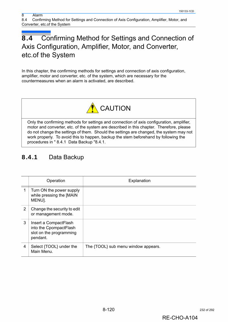
8 Alarm8.4 Confirming Method for Settings and Connection of Axis Configuration, Amplifier, Motor, and Converter, etc.of the System
150133-1CD
8.4 Confirming Method for Settings and Connection of Axis Configuration, Amplifier, Motor, and Converter, etc.of the System
In this chapter, the confirming methods for settings and connection of axis configuration, amplifier, motor and converter, etc. of the system, which are necessary for the countermeasures when an alarm is activated, are described.
8.4.1 Data Backup
Only the confirming methods for settings and connection of axis configuration, amplifier, motor and converter, etc. of the system are described in this chapter. Therefore, please do not change the settings of them. Should the settings are changed, the system may not work properly. To avoid this to happen, backup the stem beforehand by following the procedures in " 8.4.1 Data Backup "8.4.1.
Operation Explanation
1 Turn ON the power supply while pressing the [MAIN MENU].
2 Change the security to edit or management mode.
3 Insert a CompactFlash into the CpompactFlash slot on the programming pendant.
4 Select {TOOL} under the Main Menu.
The {TOOL} sub menu window appears.
8-120
RE-CHO-A104
232 of 292
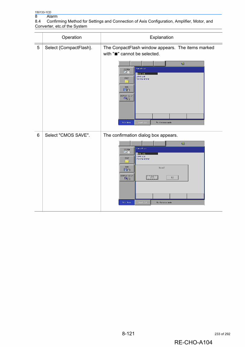
8 Alarm8.4 Confirming Method for Settings and Connection of Axis Configuration, Amplifier, Motor, and Converter, etc.of the System
150133-1CD
5 Select {CompactFlash}. The ConpactFlash window appears. The items marked with "■" cannot be selected.
6 Select "CMOS SAVE". The confirmation dialog box appears.
Operation Explanation
8-121
RE-CHO-A104
233 of 292
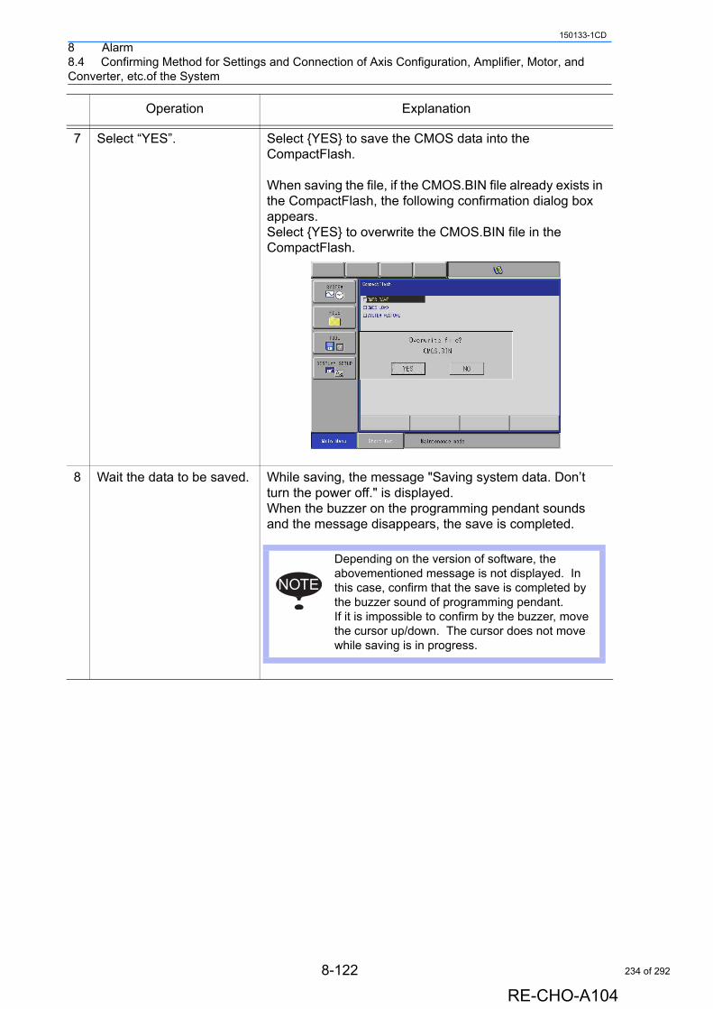
8 Alarm8.4 Confirming Method for Settings and Connection of Axis Configuration, Amplifier, Motor, and Converter, etc.of the System
150133-1CD
7 Select “YES”. Select {YES} to save the CMOS data into the CompactFlash.
When saving the file, if the CMOS.BIN file already exists in the CompactFlash, the following confirmation dialog box appears. Select {YES} to overwrite the CMOS.BIN file in the CompactFlash.
8 Wait the data to be saved. While saving, the message "Saving system data. Don’t turn the power off." is displayed. When the buzzer on the programming pendant sounds and the message disappears, the save is completed.
Operation Explanation
Depending on the version of software, the abovementioned message is not displayed. In this case, confirm that the save is completed by the buzzer sound of programming pendant. If it is impossible to confirm by the buzzer, move the cursor up/down. The cursor does not move while saving is in progress.
NOTE
8-122
RE-CHO-A104
234 of 292
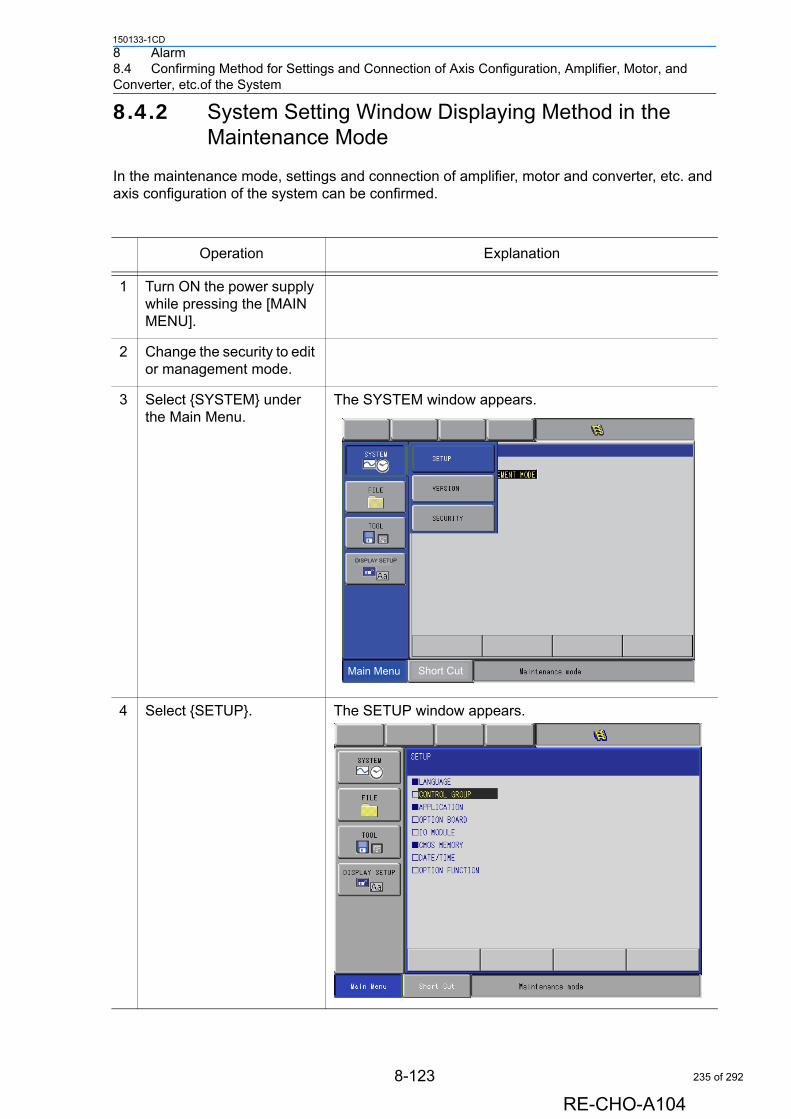
8 Alarm8.4 Confirming Method for Settings and Connection of Axis Configuration, Amplifier, Motor, and Converter, etc.of the System
150133-1CD
8.4.2 System Setting Window Displaying Method in the Maintenance Mode
In the maintenance mode, settings and connection of amplifier, motor and converter, etc. and axis configuration of the system can be confirmed.
Operation Explanation
1 Turn ON the power supply while pressing the [MAIN MENU].
2 Change the security to edit or management mode.
3 Select {SYSTEM} under the Main Menu.
The SYSTEM window appears.
4 Select {SETUP}. The SETUP window appears.
Main Menu Short Cut
DISPLAY SETUP
8-123
RE-CHO-A104
235 of 292
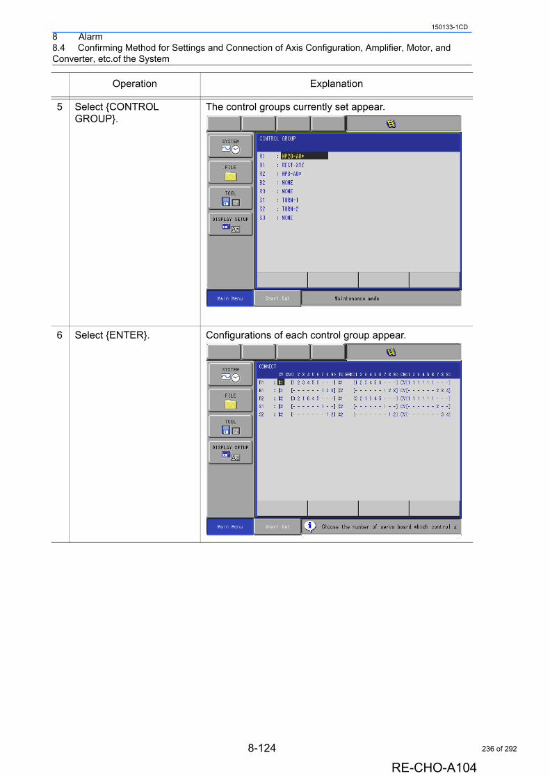
8 Alarm8.4 Confirming Method for Settings and Connection of Axis Configuration, Amplifier, Motor, and Converter, etc.of the System
150133-1CD
5 Select {CONTROL GROUP}.
The control groups currently set appear.
6 Select {ENTER}. Configurations of each control group appear.
Operation Explanation
8-124
RE-CHO-A104
236 of 292

8 Alarm8.4 Confirming Method for Settings and Connection of Axis Configuration, Amplifier, Motor, and Converter, etc.of the System
150133-1CD
8.4.3 Confirmation of Servo Control Board Settings
Corresponding servo control board (SV#1 to 4) for each control group can be confirmed.
Confirmation on the Setting Window
On the setting window, confirmation of the corresponding servo control board (SV#1 to 4) for each control group is possible.Display the window below by following the procedures described in " Fig. 8.4.2 System Setting Window Displaying Method in the Maintenance Mode ", and then, corresponding servo control board for each control group can be confirmed.The word SV shows the servo control board and each #1 and #2 shows the servo control board number.
(The part circled with .)
- Details of the window above.R1 (Robot 1) is set to the servo control board1 (SV#1).B1 (Base 1) is set to the servo control board1 (SV#1).R2 (Robot 2) is set to the servo control board2 (SV#2).S1 (Station 1) is set to the servo control board2 (SV#2).S2 (Station 2) is set to the servo control board2 (SV#2).
8-125
RE-CHO-A104
237 of 292
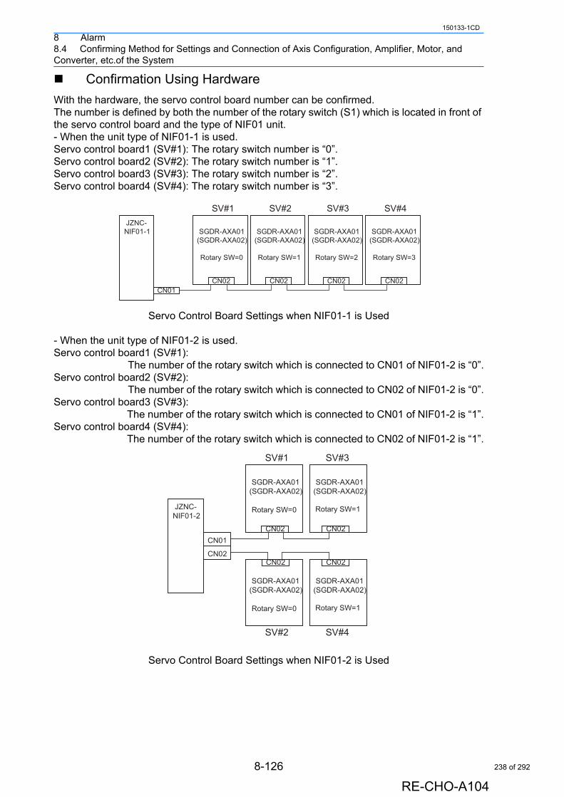
8 Alarm8.4 Confirming Method for Settings and Connection of Axis Configuration, Amplifier, Motor, and Converter, etc.of the System
150133-1CD
Confirmation Using Hardware
With the hardware, the servo control board number can be confirmed.The number is defined by both the number of the rotary switch (S1) which is located in front of the servo control board and the type of NIF01 unit.- When the unit type of NIF01-1 is used.Servo control board1 (SV#1): The rotary switch number is “0”.Servo control board2 (SV#2): The rotary switch number is “1”.Servo control board3 (SV#3): The rotary switch number is “2”.Servo control board4 (SV#4): The rotary switch number is “3”.
Servo Control Board Settings when NIF01-1 is Used
- When the unit type of NIF01-2 is used.Servo control board1 (SV#1): The number of the rotary switch which is connected to CN01 of NIF01-2 is “0”.Servo control board2 (SV#2): The number of the rotary switch which is connected to CN02 of NIF01-2 is “0”.Servo control board3 (SV#3): The number of the rotary switch which is connected to CN01 of NIF01-2 is “1”.Servo control board4 (SV#4): The number of the rotary switch which is connected to CN02 of NIF01-2 is “1”.
Servo Control Board Settings when NIF01-2 is Used
JZNC-NIF01-1 SGDR-AXA01
(SGDR-AXA02)
Rotary SW=0
SGDR-AXA01(SGDR-AXA02)
Rotary SW=1
SGDR-AXA01(SGDR-AXA02)
Rotary SW=2
SGDR-AXA01(SGDR-AXA02)
Rotary SW=3
CN01
SV#1 SV#3SV#2 SV#4
CN02 CN02 CN02 CN02
JZNC-NIF01-2
SGDR-AXA01(SGDR-AXA02)
Rotary SW=0
SGDR-AXA01(SGDR-AXA02)
Rotary SW=1
SGDR-AXA01(SGDR-AXA02)
Rotary SW=0
SGDR-AXA01(SGDR-AXA02)
Rotary SW=1
CN01
CN02
SV#1 SV#3
SV#2 SV#4
CN02 CN02
CN02 CN02
8-126
RE-CHO-A104
238 of 292
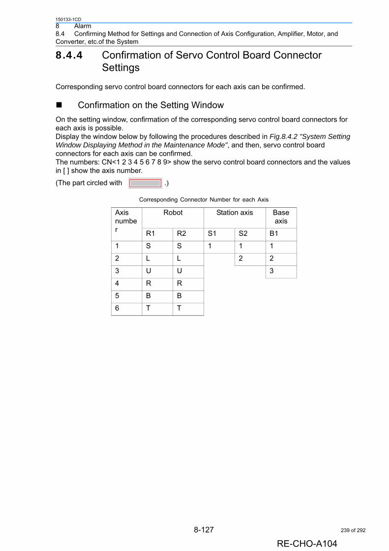
8 Alarm8.4 Confirming Method for Settings and Connection of Axis Configuration, Amplifier, Motor, and Converter, etc.of the System
150133-1CD
8.4.4 Confirmation of Servo Control Board Connector Settings
Corresponding servo control board connectors for each axis can be confirmed.
Confirmation on the Setting Window
On the setting window, confirmation of the corresponding servo control board connectors for each axis is possible.Display the window below by following the procedures described in Fig.8.4.2 "System Setting Window Displaying Method in the Maintenance Mode", and then, servo control board connectors for each axis can be confirmed.The numbers: CN<1 2 3 4 5 6 7 8 9> show the servo control board connectors and the values in [ ] show the axis number.
(The part circled with .)
Corresponding Connector Number for each Axis
Axis number
Robot Station axis Base axis
R1 R2 S1 S2 B1
1 S S 1 1 1
2 L L 2 2
3 U U 3
4 R R
5 B B
6 T T
8-127
RE-CHO-A104
239 of 292
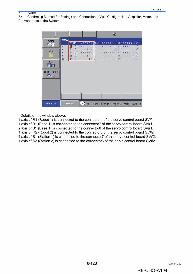
8 Alarm8.4 Confirming Method for Settings and Connection of Axis Configuration, Amplifier, Motor, and Converter, etc.of the System
150133-1CD
- Details of the window above.1 axis of R1 (Robot 1) is connected to the connector1 of the servo control board SV#11 axis of B1 (Base 1) is connected to the connector7 of the servo control board SV#1.2 axis of B1 (Base 1) is connected to the connector8 of the servo control board SV#1.1 axis of R2 (Robot 2) is connected to the connector3 of the servo control board SV#2.1 axis of S1 (Station 1) is connected to the connector7 of the servo control board SV#2.1 axis of S2 (Station 2) is connected to the connector8 of the servo control board SV#2.
8-128
RE-CHO-A104
240 of 292
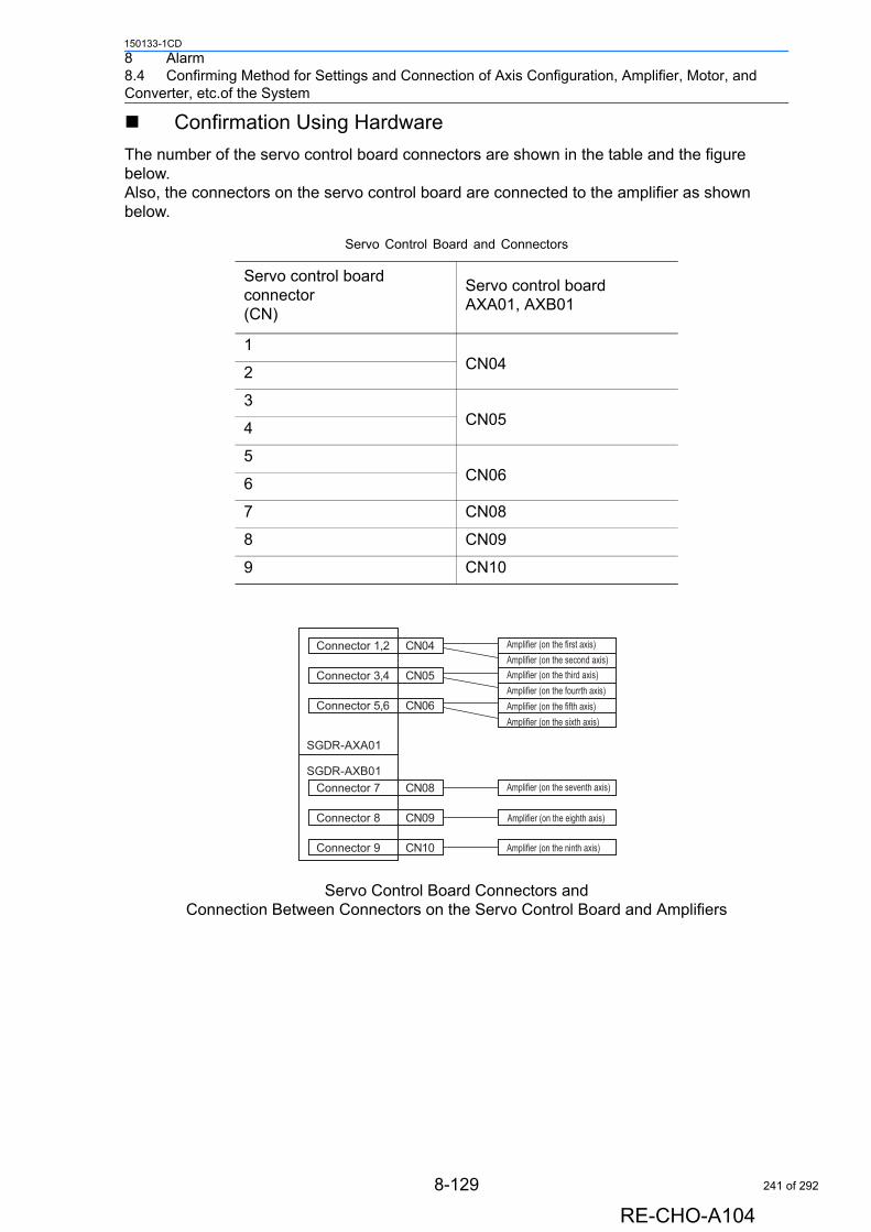
8 Alarm8.4 Confirming Method for Settings and Connection of Axis Configuration, Amplifier, Motor, and Converter, etc.of the System
150133-1CD
Confirmation Using Hardware
The number of the servo control board connectors are shown in the table and the figure below.Also, the connectors on the servo control board are connected to the amplifier as shown below.
Servo Control Board Connectors and Connection Between Connectors on the Servo Control Board and Amplifiers
Servo Control Board and Connectors
Servo control board connector(CN)
Servo control board AXA01, AXB01
1CN042
3CN054
5CN066
7 CN08
8 CN09
9 CN10
SGDR-AXA01
SGDR-AXB01
CN04
CN05
CN06
CN08
CN10
CN09
Connector 1,2 Amplifier (on the first axis)Amplifier (on the second axis)Amplifier (on the third axis)Amplifier (on the fourrth axis)Amplifier (on the fifth axis)Amplifier (on the sixth axis)
Amplifier (on the seventh axis)
Amplifier (on the eighth axis)
Amplifier (on the ninth axis)
Connector 3,4
Connector 5,6
Connector 7
Connector 8
Connector 9
8-129
RE-CHO-A104
241 of 292
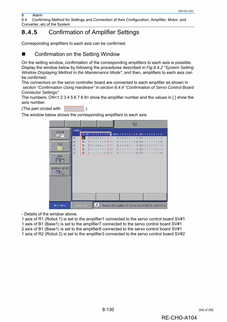
8 Alarm8.4 Confirming Method for Settings and Connection of Axis Configuration, Amplifier, Motor, and Converter, etc.of the System
150133-1CD
8.4.5 Confirmation of Amplifier Settings
Corresponding amplifiers to each axis can be confirmed.
Confirmation on the Setting Window
On the setting window, confirmation of the corresponding amplifiers to each axis is possible.Display the window below by following the procedures described in Fig.8.4.2 "System Setting Window Displaying Method in the Maintenance Mode", and then, amplifiers to each axis can be confirmed.The connectors on the servo controller board are connected to each amplifier as shown in section “Confirmation Using Hardware” in section 8.4.4 “Confirmation of Servo Control Board Connector Settings”.The numbers: CN<1 2 3 4 5 6 7 8 9> show the amplifier number and the values in [ ] show the axis number.
(The part circled with .)The window below shows the corresponding amplifiers to each axis.
- Details of the window above.1 axis of R1 (Robot 1) is set to the amplifier1 connected to the servo control board SV#11 axis of B1 (Base1) is set to the amplifier7 connected to the servo control board SV#12 axis of B1 (Base1) is set to the amplifier8 connected to the servo control board SV#11 axis of R2 (Robot 2) is set to the amplifier3 connected to the servo control board SV#2
8-130
RE-CHO-A104
242 of 292
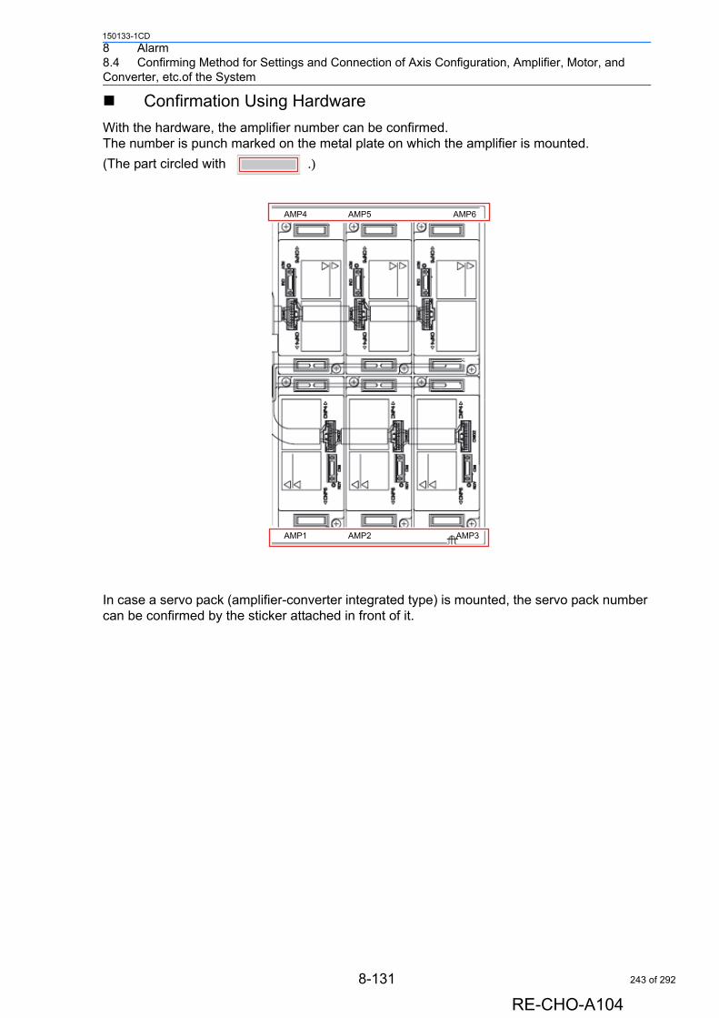
8 Alarm8.4 Confirming Method for Settings and Connection of Axis Configuration, Amplifier, Motor, and Converter, etc.of the System
150133-1CD
Confirmation Using Hardware
With the hardware, the amplifier number can be confirmed.The number is punch marked on the metal plate on which the amplifier is mounted.
(The part circled with .)
In case a servo pack (amplifier-converter integrated type) is mounted, the servo pack number can be confirmed by the sticker attached in front of it.
AMP4 AMP5 AMP6
AMP1 AMP2 AMP3
8-131
RE-CHO-A104
243 of 292
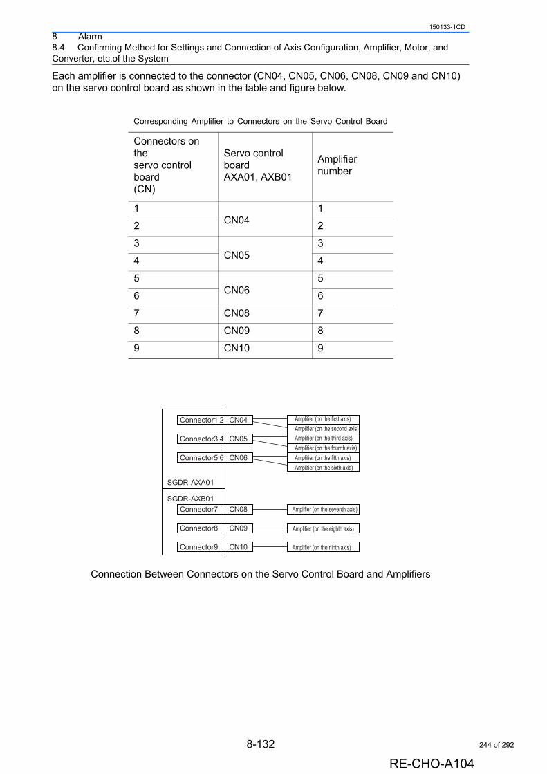
8 Alarm8.4 Confirming Method for Settings and Connection of Axis Configuration, Amplifier, Motor, and Converter, etc.of the System
150133-1CD
Each amplifier is connected to the connector (CN04, CN05, CN06, CN08, CN09 and CN10) on the servo control board as shown in the table and figure below.
Connection Between Connectors on the Servo Control Board and Amplifiers
Corresponding Amplifier to Connectors on the Servo Control Board
Connectors on the servo control board(CN)
Servo control board AXA01, AXB01
Amplifier number
1CN04
1
2 2
3CN05
3
4 4
5CN06
5
6 6
7 CN08 7
8 CN09 8
9 CN10 9
SGDR-AXA01
SGDR-AXB01
CN04
CN05
CN06
CN08
CN10
CN09
Connector1,2
Connector3,4
Connector5,6
Connector7
Connector8
Connector9
Amplifier (on the first axis)Amplifier (on the second axis)Amplifier (on the third axis)Amplifier (on the fourrth axis)Amplifier (on the fifth axis)Amplifier (on the sixth axis)
Amplifier (on the seventh axis)
Amplifier (on the eighth axis)
Amplifier (on the ninth axis)
8-132
RE-CHO-A104
244 of 292

8 Alarm8.4 Confirming Method for Settings and Connection of Axis Configuration, Amplifier, Motor, and Converter, etc.of the System
150133-1CD
8.4.6 Confirmation of Power Supply Contactor Unit Settings
Corresponding power supply contactor unit for each control group can be confirmed.
Confirmation on the Setting Window
On the setting window, confirmation of the corresponding power supply contactor unit for each control group is possible.Display the window below by following the procedures described in Fig. 8.4.2 “System Setting Window Displaying Method in the Maintenance Mode”, and then, corresponding power supply contactor unit for each control group can be confirmed.The word TU indicates the power supply contactor unit and #1 and #2 show the number of power supply contactor unit.
(The part circled with .)
- Details of the window above.R1 (Robot 1) is set to power supply contactor unit 1 (TU#1).B1 (Base1) is set to power supply contactor unit 2 (TU#2).R2 (Robot 2) is set to power supply contactor unit 1 (TU#1).S1 (Station 1) is set to power supply contactor unit 2 (TU#2).S2 (Station 2) is set to power supply contactor unit 2 (TU#2).
8-133
RE-CHO-A104
245 of 292
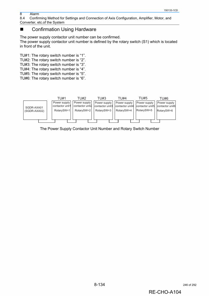
8 Alarm8.4 Confirming Method for Settings and Connection of Axis Configuration, Amplifier, Motor, and Converter, etc.of the System
150133-1CD
Confirmation Using Hardware
The power supply contactor unit number can be confirmed.The power supply contactor unit number is defined by the rotary switch (S1) which is located in front of the unit.
TU#1: The rotary switch number is “1”.TU#2: The rotary switch number is “2”.TU#3: The rotary switch number is “3”.TU#4: The rotary switch number is “4”.TU#5: The rotary switch number is “5”.TU#6: The rotary switch number is “6”.
The Power Supply Contactor Unit Number and Rotary Switch Number
SGDR-AXA01(SGDR-AXA02)
Power supply contactor unit1RotarySW=1
TU#1Power supply contactor unit2RotarySW=2
TU#2Power supply contactor unit3RotarySW=3
TU#3Power supply contactor unit4RotarySW=4
TU#4Power supply contactor unit5RotarySW=5
TU#5Power supply contactor unit6RotarySW=6
TU#6
8-134
RE-CHO-A104
246 of 292
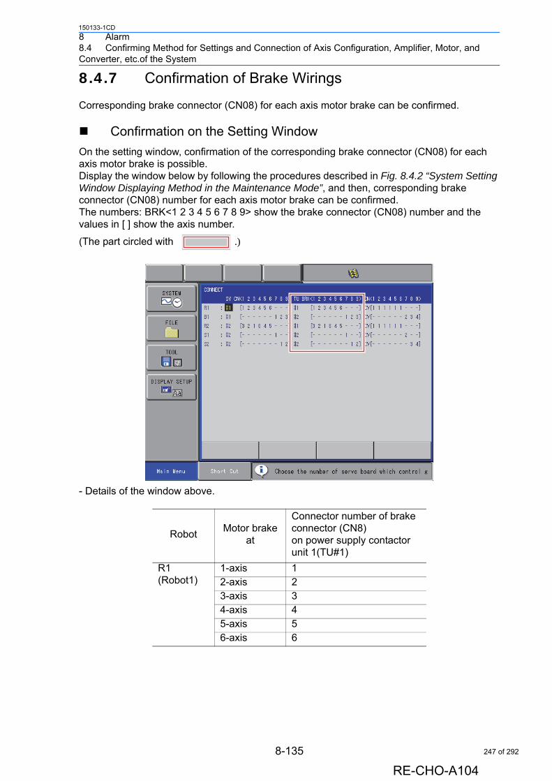
8 Alarm8.4 Confirming Method for Settings and Connection of Axis Configuration, Amplifier, Motor, and Converter, etc.of the System
150133-1CD
8.4.7 Confirmation of Brake Wirings
Corresponding brake connector (CN08) for each axis motor brake can be confirmed.
Confirmation on the Setting Window
On the setting window, confirmation of the corresponding brake connector (CN08) for each axis motor brake is possible.Display the window below by following the procedures described in Fig. 8.4.2 “System Setting Window Displaying Method in the Maintenance Mode”, and then, corresponding brake connector (CN08) number for each axis motor brake can be confirmed.The numbers: BRK<1 2 3 4 5 6 7 8 9> show the brake connector (CN08) number and the values in [ ] show the axis number.
(The part circled with .)
- Details of the window above.
RobotMotor brake
at
Connector number of brake connector (CN8) on power supply contactor unit 1(TU#1)
R1 (Robot1)
1-axis 12-axis 23-axis 34-axis 45-axis 56-axis 6
8-135
RE-CHO-A104
247 of 292
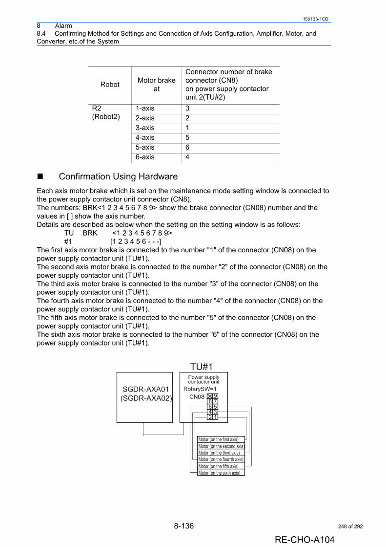
8 Alarm8.4 Confirming Method for Settings and Connection of Axis Configuration, Amplifier, Motor, and Converter, etc.of the System
150133-1CD
Confirmation Using Hardware
Each axis motor brake which is set on the maintenance mode setting window is connected to the power supply contactor unit connector (CN8).The numbers: BRK<1 2 3 4 5 6 7 8 9> show the brake connector (CN08) number and the values in [ ] show the axis number.Details are described as below when the setting on the setting window is as follows: TU BRK <1 2 3 4 5 6 7 8 9>
#1 [1 2 3 4 5 6 - - -]The first axis motor brake is connected to the number "1" of the connector (CN08) on the power supply contactor unit (TU#1).The second axis motor brake is connected to the number "2" of the connector (CN08) on the power supply contactor unit (TU#1).The third axis motor brake is connected to the number "3" of the connector (CN08) on the power supply contactor unit (TU#1).The fourth axis motor brake is connected to the number "4" of the connector (CN08) on the power supply contactor unit (TU#1).The fifth axis motor brake is connected to the number "5" of the connector (CN08) on the power supply contactor unit (TU#1).The sixth axis motor brake is connected to the number "6" of the connector (CN08) on the power supply contactor unit (TU#1).
RobotMotor brake
at
Connector number of brake connector (CN8) on power supply contactor unit 2(TU#2)
R2 (Robot2)
1-axis 32-axis 23-axis 14-axis 55-axis 66-axis 4
SGDR-AXA01(SGDR-AXA02)
Power supplycontactor unit
RotarySW=1
123456789
TU#1
CN08
Motor (on the second axis)Motor (on the first axis)
Motor (on the third axis)Motor (on the fourrth axis)Motor (on the fifth axis)Motor (on the sixth axis)
8-136
RE-CHO-A104
248 of 292
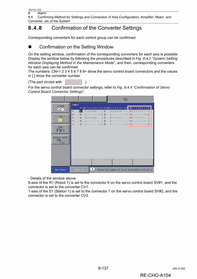
8 Alarm8.4 Confirming Method for Settings and Connection of Axis Configuration, Amplifier, Motor, and Converter, etc.of the System
150133-1CD
8.4.8 Confirmation of the Converter Settings
Corresponding converters for each control group can be confirmed.
Confirmation on the Setting Window
On the setting window, confirmation of the corresponding converters for each axis is possible.Display the window below by following the procedures described in Fig. 8.4.2 “System Setting Window Displaying Method in the Maintenance Mode”, and then, corresponding converters for each axis can be confirmed.The numbers: CN<1 2 3 4 5 6 7 8 9> show the servo control board connectors and the values in [ ] show the converter number.
(The part circled with .)For the servo control board connector settings, refer to Fig. 8.4.4 “Confirmation of Servo Control Board Connector Settings”.
- Details of the window above.6-axis of the R1 (Robot 1) is set to the connector 6 on the servo control board SV#1, and the connector is set to the converter CV1.1-axis of the S1 (Station 1) is set to the connector 7 on the servo control board SV#2, and the connector is set to the converter CV2.
8-137
RE-CHO-A104
249 of 292
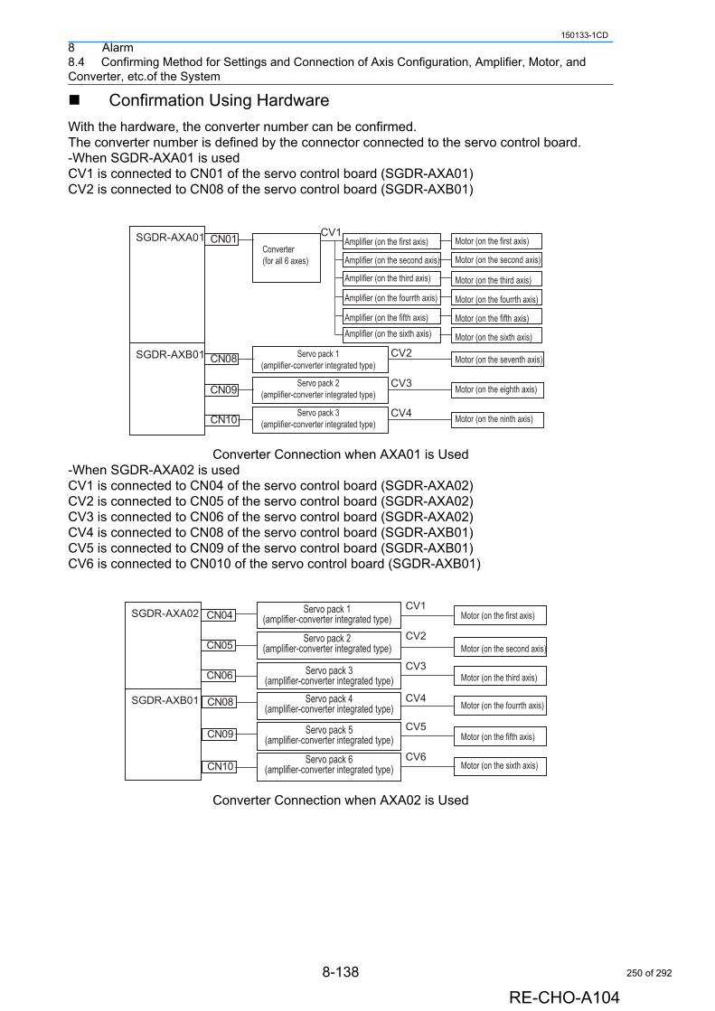
8 Alarm8.4 Confirming Method for Settings and Connection of Axis Configuration, Amplifier, Motor, and Converter, etc.of the System
150133-1CD
Confirmation Using Hardware
With the hardware, the converter number can be confirmed.The converter number is defined by the connector connected to the servo control board.-When SGDR-AXA01 is usedCV1 is connected to CN01 of the servo control board (SGDR-AXA01)CV2 is connected to CN08 of the servo control board (SGDR-AXB01)
Converter Connection when AXA01 is Used-When SGDR-AXA02 is usedCV1 is connected to CN04 of the servo control board (SGDR-AXA02)CV2 is connected to CN05 of the servo control board (SGDR-AXA02)CV3 is connected to CN06 of the servo control board (SGDR-AXA02)CV4 is connected to CN08 of the servo control board (SGDR-AXB01)CV5 is connected to CN09 of the servo control board (SGDR-AXB01)CV6 is connected to CN010 of the servo control board (SGDR-AXB01)
Converter Connection when AXA02 is Used
SGDR-AXA01 CN01 CV1
CV2CN08SGDR-AXB01
CN09
CN10
CV3
CV4
Amplifier (on the first axis)Converter (for all 6 axes)
Servo pack 2(amplifier-converter integrated type)
Servo pack 3(amplifier-converter integrated type)
Servo pack 1(amplifier-converter integrated type)
Amplifier (on the second axis)
Amplifier (on the third axis)
Amplifier (on the fourrth axis)
Amplifier (on the fifth axis)Amplifier (on the sixth axis)
Motor (on the first axis)
Motor (on the second axis)
Motor (on the third axis)
Motor (on the fourrth axis)
Motor (on the fifth axis)
Motor (on the sixth axis)
Motor (on the seventh axis)
Motor (on the eighth axis)
Motor (on the ninth axis)
SGDR-AXA02
SGDR-AXB01
CN04
CN05
CN06
CN08
CN09
CN10
CV1
CV2
CV3
CV4
CV5
CV6
Motor (on the first axis)
Motor (on the second axis)
Motor (on the third axis)
Motor (on the fourrth axis)
Motor (on the fifth axis)
Motor (on the sixth axis)
Servo pack 2(amplifier-converter integrated type)
Servo pack 3(amplifier-converter integrated type)
Servo pack 4(amplifier-converter integrated type)
Servo pack 5(amplifier-converter integrated type)
Servo pack 6(amplifier-converter integrated type)
Servo pack 1(amplifier-converter integrated type)
8-138
RE-CHO-A104
250 of 292

9 Error9.1 Error Message List
150133-1CD
9 Error
9.1 Error Message List
Error warns the operator not to advance to the next operation caused by a wrong operation or the access method when using the programming pendant or an external equipment (computer, PLC, etc.).When an error occurs, confirm the content of the error then release the error.
To release the error, perform either of the following operations:• Press [CANCEL] on programming pendant.• Input alarm/error reset signal (system input).
When two or more errors occur, appears in the message display area. Activate the message display area and press [SELECT] to view the list of current errors.
To view details of the selected error contents, select "HELP". To close the error list, select "CLOSE". To release all the errors, press [CANCEL].
An error is different from an alarm because it does not stop the robot even if it occurred while the robot was operated (during playback).
NOTE
Main Menu ShortCut Cannot insert/modify/delete for axis detachment
HELP
CLOSE
5 / 9
Cannot load macro job at current security mode
Cannot insert/modify/delete for group axis detachment
Cannot insert/modify/delete for axis detachment
9-1
RE-CHO-A104
251 of 292
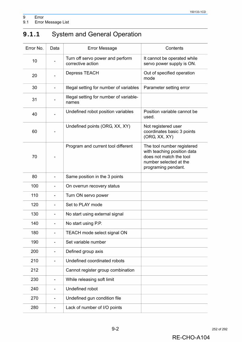
9 Error9.1 Error Message List
150133-1CD
9.1.1 System and General Operation
Error No. Data Error Message Contents
10 -Turn off servo power and perform corrective action
It cannot be operated while servo power supply is ON.
20 -Depress TEACH Out of specified operation
mode
30 - Illegal setting for number of variables Parameter setting error
31 -Illegal setting for number of variable-names
40 -Undefined robot position variables Position variable cannot be
used.
60 -Undefined points (ORG, XX, XY) Not registered user
coordinates basic 3 points (ORG, XX, XY)
70 -
Program and current tool different The tool number registered with teaching position data does not match the tool number selected at the programing pendant.
80 - Same position in the 3 points
100 - On overrun recovery status
110 - Turn ON servo power
120 - Set to PLAY mode
130 - No start using external signal
140 - No start using P.P.
180 - TEACH mode select signal ON
190 - Set variable number
200 - Defined group axis
210 - Undefined coordinated robots
212 Cannot register group combination
230 - While releasing soft limit
240 - Undefined robot
270 - Undefined gun condition file
280 - Lack of number of I/O points
9-2
RE-CHO-A104
252 of 292
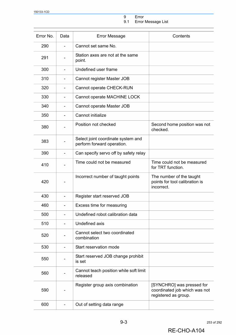
9 Error9.1 Error Message List
150133-1CD
290 - Cannot set same No.
291 -Station axes are not at the same point.
300 - Undefined user frame
310 - Cannot register Master JOB
320 - Cannot operate CHECK-RUN
330 - Cannot operate MACHINE LOCK
340 - Cannot operate Master JOB
350 - Cannot initialize
380 -Position not checked Second home position was not
checked.
383 -Select joint coordinate system and perform forward operation.
390 - Can specify servo off by safety relay
410 -Time could not be measured Time could not be measured
for TRT function.
420 -Incorrect number of taught points The number of the taught
points for tool calibration is incorrect.
430 - Register start reserved JOB
460 - Excess time for measuring
500 - Undefined robot calibration data
510 - Undefined axis
520 -Cannot select two coordinated combination
530 - Start reservation mode
550 -Start reserved JOB change prohibit is set
560 -Cannot teach position while soft limit released
590 -Register group axis combination [SYNCHRO] was pressed for
coordinated job which was not registered as group.
600 - Out of setting data range
Error No. Data Error Message Contents
9-3
RE-CHO-A104
253 of 292
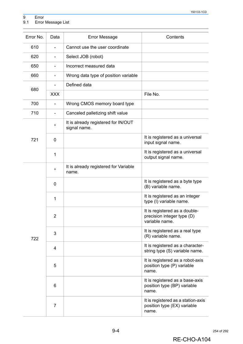
9 Error9.1 Error Message List
150133-1CD
610 - Cannot use the user coordinate
620 - Select JOB (robot)
650 - Incorrect measured data
660 - Wrong data type of position variable
680- Defined data
XXX File No.
700 - Wrong CMOS memory board type
710 - Canceled palletizing shift value
721
∗ It is already registered for IN/OUT signal name.
0It is registered as a universal input signal name.
1It is registered as a universal output signal name.
722
∗ It is already registered for Variable name.
0It is registered as a byte type (B) variable name.
1It is registered as an integer type (I) variable name.
2It is registered as a double-precision integer type (D) variable name.
3It is registered as a real type (R) variable name.
4It is registered as a character-string type (S) variable name.
5It is registered as a robot-axis position type (P) variable name.
6It is registered as a base-axis position type (BP) variable name.
7It is registered as a station-axis position type (EX) variable name.
Error No. Data Error Message Contents
9-4
RE-CHO-A104
254 of 292

9 Error9.1 Error Message List
150133-1CD
723
∗ It is already registered for Local variable name.
0It is registered as a byte type local (LB) variable name.
1It is registered as an integer type local (LI) variable name.
2It is registered as a double-precision integer type local (LD) variable name.
3It is registered as a real type local (LR) variable name.
4It is registered as a character-string type local (LS) variable name.
5It is registered as a robot-axis position type local (LP) variable name.
6It is registered as a base-axis position type local (LBP) variable name.
7It is registered as a station-axis position type local (LEX) variable name.
Error No. Data Error Message Contents
9-5
RE-CHO-A104
255 of 292
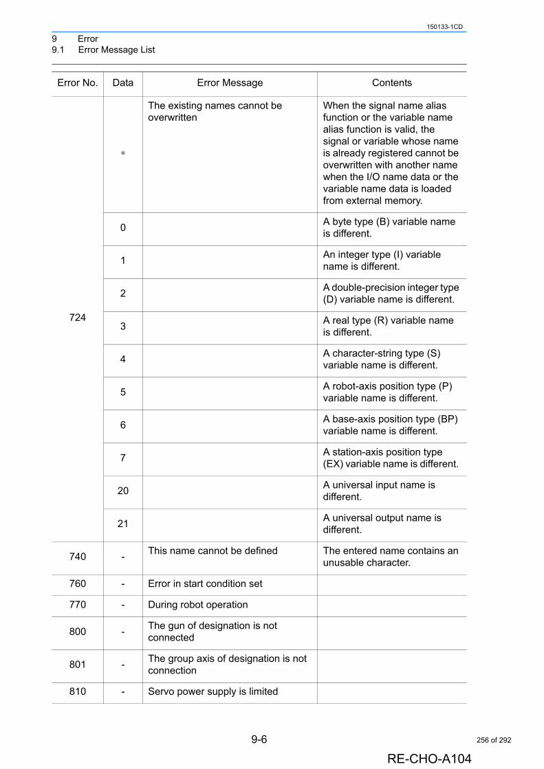
9 Error9.1 Error Message List
150133-1CD
724
∗
The existing names cannot be overwritten
When the signal name alias function or the variable name alias function is valid, the signal or variable whose name is already registered cannot be overwritten with another name when the I/O name data or the variable name data is loaded from external memory.
0A byte type (B) variable name is different.
1An integer type (I) variable name is different.
2A double-precision integer type (D) variable name is different.
3A real type (R) variable name is different.
4A character-string type (S) variable name is different.
5A robot-axis position type (P) variable name is different.
6A base-axis position type (BP) variable name is different.
7A station-axis position type (EX) variable name is different.
20A universal input name is different.
21A universal output name is different.
740 -This name cannot be defined The entered name contains an
unusable character.
760 - Error in start condition set
770 - During robot operation
800 -The gun of designation is not connected
801 -The group axis of designation is not connection
810 - Servo power supply is limited
Error No. Data Error Message Contents
9-6
RE-CHO-A104
256 of 292
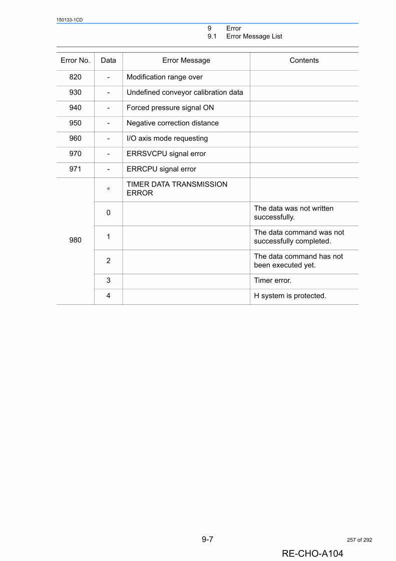
9 Error9.1 Error Message List
150133-1CD
820 - Modification range over
930 - Undefined conveyor calibration data
940 - Forced pressure signal ON
950 - Negative correction distance
960 - I/O axis mode requesting
970 - ERRSVCPU signal error
971 - ERRCPU signal error
980
∗ TIMER DATA TRANSMISSION ERROR
0The data was not written successfully.
1The data command was not successfully completed.
2The data command has not been executed yet.
3 Timer error.
4 H system is protected.
Error No. Data Error Message Contents
9-7
RE-CHO-A104
257 of 292
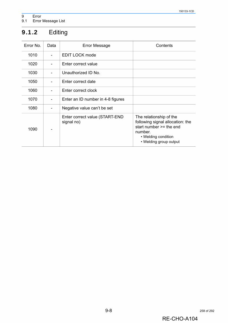
9 Error9.1 Error Message List
150133-1CD
9.1.2 Editing
Error No. Data Error Message Contents
1010 - EDIT LOCK mode
1020 - Enter correct value
1030 - Unauthorized ID No.
1050 - Enter correct date
1060 - Enter correct clock
1070 - Enter an ID number in 4-8 figures
1080 - Negative value can’t be set
1090 -
Enter correct value (START-END signal no)
The relationship of the following signal allocation: the start number >= the end number.
• Welding condition• Welding group output
9-8
RE-CHO-A104
258 of 292
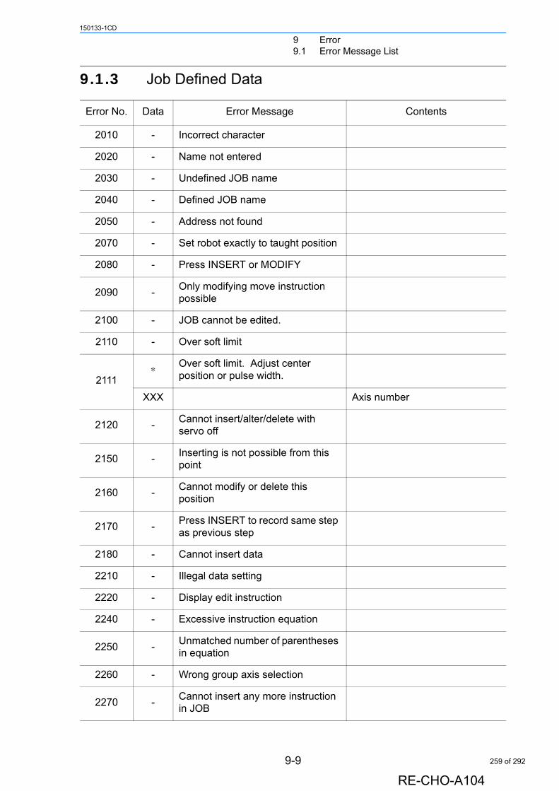
9 Error9.1 Error Message List
150133-1CD
9.1.3 Job Defined Data
Error No. Data Error Message Contents
2010 - Incorrect character
2020 - Name not entered
2030 - Undefined JOB name
2040 - Defined JOB name
2050 - Address not found
2070 - Set robot exactly to taught position
2080 - Press INSERT or MODIFY
2090 -Only modifying move instruction possible
2100 - JOB cannot be edited.
2110 - Over soft limit
2111∗ Over soft limit. Adjust center
position or pulse width.
XXX Axis number
2120 -Cannot insert/alter/delete with servo off
2150 -Inserting is not possible from this point
2160 -Cannot modify or delete this position
2170 -Press INSERT to record same step as previous step
2180 - Cannot insert data
2210 - Illegal data setting
2220 - Display edit instruction
2240 - Excessive instruction equation
2250 -Unmatched number of parentheses in equation
2260 - Wrong group axis selection
2270 -Cannot insert any more instruction in JOB
9-9
RE-CHO-A104
259 of 292
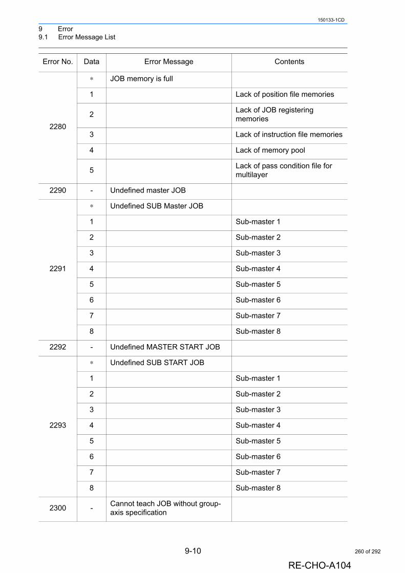
9 Error9.1 Error Message List
150133-1CD
2280
∗ JOB memory is full
1 Lack of position file memories
2Lack of JOB registering memories
3 Lack of instruction file memories
4 Lack of memory pool
5Lack of pass condition file for multilayer
2290 - Undefined master JOB
2291
∗ Undefined SUB Master JOB
1 Sub-master 1
2 Sub-master 2
3 Sub-master 3
4 Sub-master 4
5 Sub-master 5
6 Sub-master 6
7 Sub-master 7
8 Sub-master 8
2292 - Undefined MASTER START JOB
2293
∗ Undefined SUB START JOB
1 Sub-master 1
2 Sub-master 2
3 Sub-master 3
4 Sub-master 4
5 Sub-master 5
6 Sub-master 6
7 Sub-master 7
8 Sub-master 8
2300 -Cannot teach JOB without group-axis specification
Error No. Data Error Message Contents
9-10
RE-CHO-A104
260 of 292
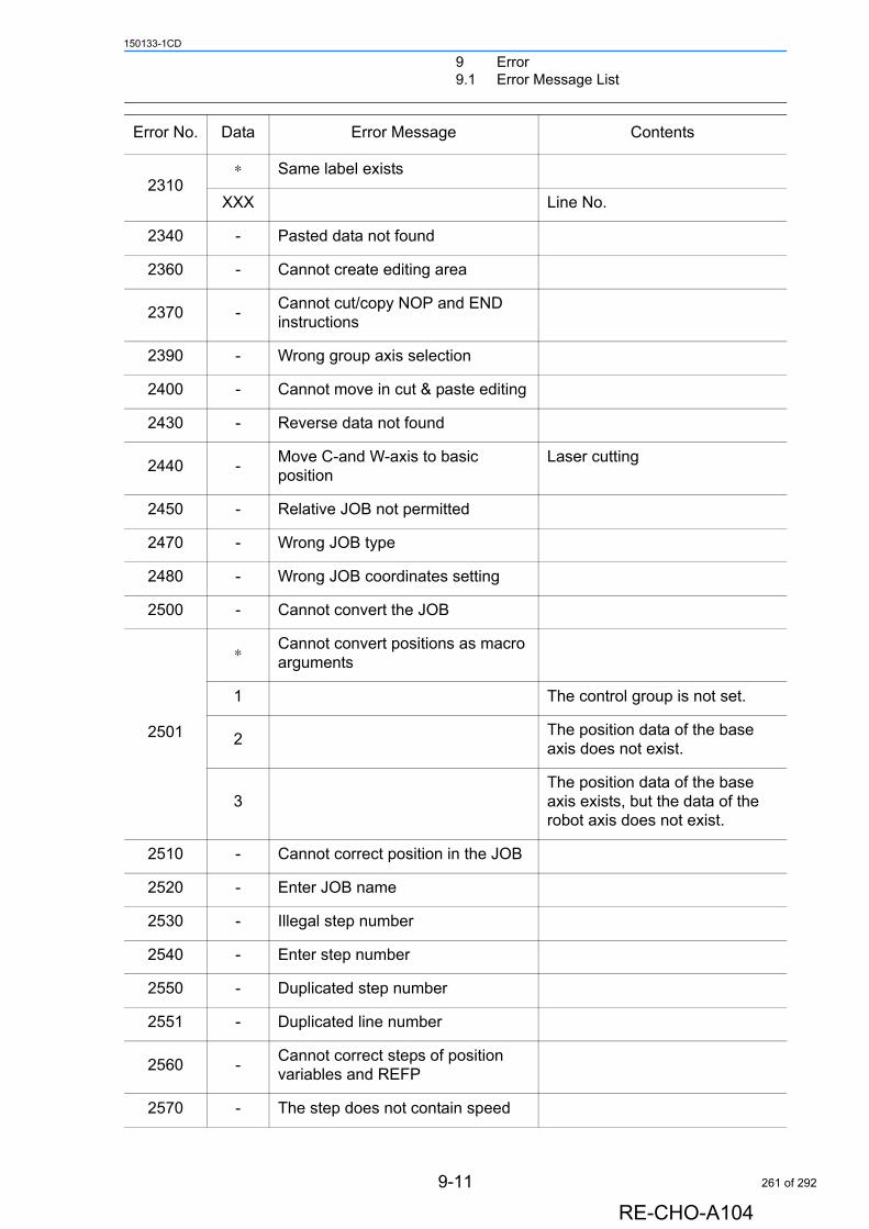
9 Error9.1 Error Message List
150133-1CD
2310∗ Same label exists
XXX Line No.
2340 - Pasted data not found
2360 - Cannot create editing area
2370 -Cannot cut/copy NOP and END instructions
2390 - Wrong group axis selection
2400 - Cannot move in cut & paste editing
2430 - Reverse data not found
2440 -Move C-and W-axis to basic position
Laser cutting
2450 - Relative JOB not permitted
2470 - Wrong JOB type
2480 - Wrong JOB coordinates setting
2500 - Cannot convert the JOB
2501
∗ Cannot convert positions as macro arguments
1 The control group is not set.
2The position data of the base axis does not exist.
3The position data of the base axis exists, but the data of the robot axis does not exist.
2510 - Cannot correct position in the JOB
2520 - Enter JOB name
2530 - Illegal step number
2540 - Enter step number
2550 - Duplicated step number
2551 - Duplicated line number
2560 -Cannot correct steps of position variables and REFP
2570 - The step does not contain speed
Error No. Data Error Message Contents
9-11
RE-CHO-A104
261 of 292
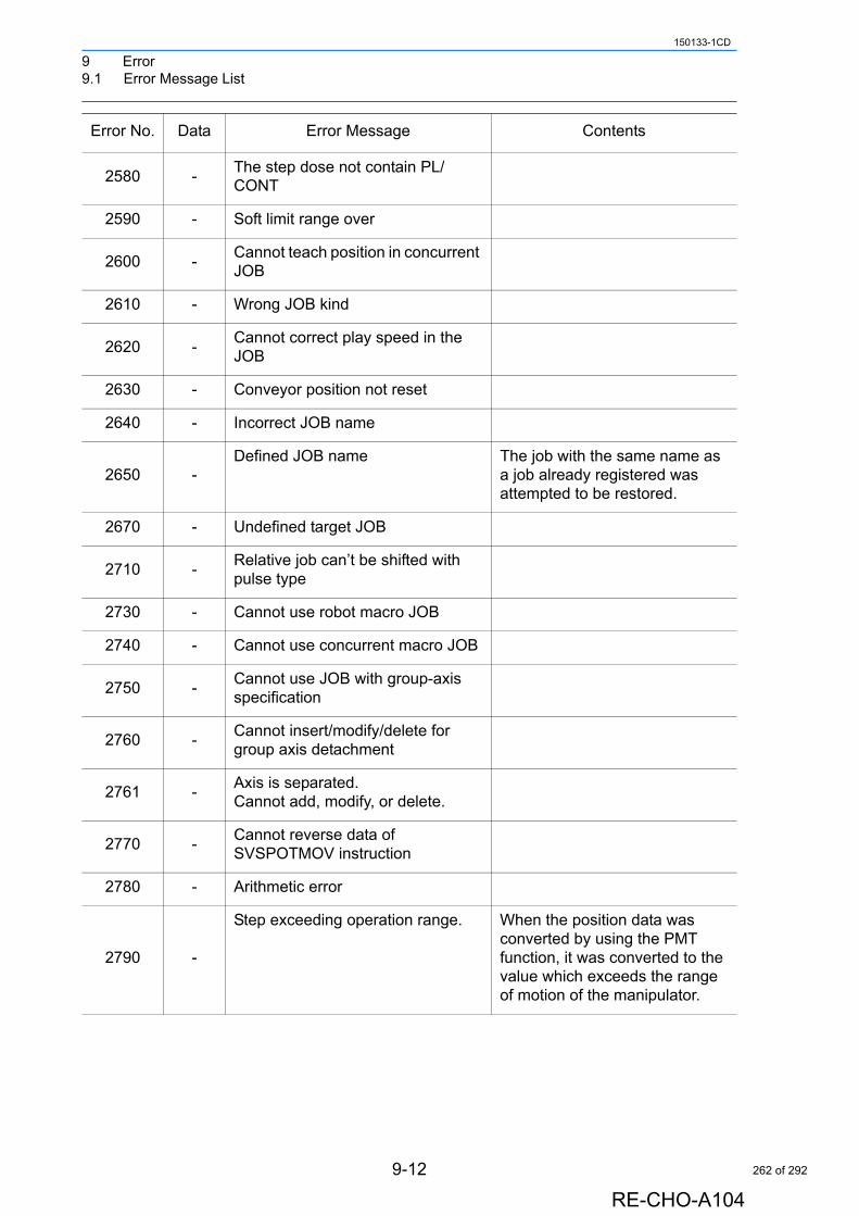
9 Error9.1 Error Message List
150133-1CD
2580 -The step dose not contain PL/CONT
2590 - Soft limit range over
2600 -Cannot teach position in concurrent JOB
2610 - Wrong JOB kind
2620 -Cannot correct play speed in the JOB
2630 - Conveyor position not reset
2640 - Incorrect JOB name
2650 -Defined JOB name The job with the same name as
a job already registered was attempted to be restored.
2670 - Undefined target JOB
2710 -Relative job can’t be shifted with pulse type
2730 - Cannot use robot macro JOB
2740 - Cannot use concurrent macro JOB
2750 -Cannot use JOB with group-axis specification
2760 -Cannot insert/modify/delete for group axis detachment
2761 -Axis is separated.Cannot add, modify, or delete.
2770 -Cannot reverse data of SVSPOTMOV instruction
2780 - Arithmetic error
2790 -
Step exceeding operation range. When the position data was converted by using the PMT function, it was converted to the value which exceeds the range of motion of the manipulator.
Error No. Data Error Message Contents
9-12
RE-CHO-A104
262 of 292

9 Error9.1 Error Message List
150133-1CD
9.1.4 External Memory Equipment
9-13
RE-CHO-A104
263 of 292
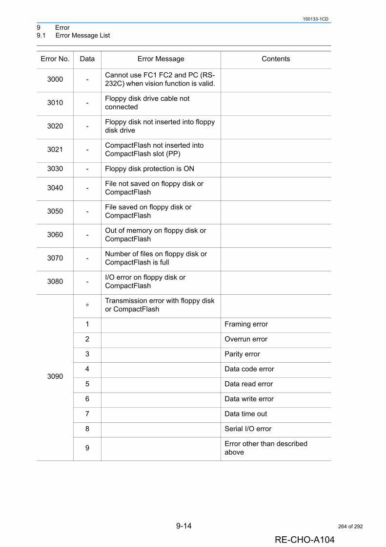
9 Error9.1 Error Message List
150133-1CD
Error No. Data Error Message Contents
3000 -Cannot use FC1 FC2 and PC (RS-232C) when vision function is valid.
3010 -Floppy disk drive cable not connected
3020 -Floppy disk not inserted into floppy disk drive
3021 -CompactFlash not inserted into CompactFlash slot (PP)
3030 - Floppy disk protection is ON
3040 -File not saved on floppy disk or CompactFlash
3050 -File saved on floppy disk or CompactFlash
3060 -Out of memory on floppy disk or CompactFlash
3070 -Number of files on floppy disk or CompactFlash is full
3080 -I/O error on floppy disk or CompactFlash
3090
∗ Transmission error with floppy disk or CompactFlash
1 Framing error
2 Overrun error
3 Parity error
4 Data code error
5 Data read error
6 Data write error
7 Data time out
8 Serial I/O error
9Error other than described above
9-14
RE-CHO-A104
264 of 292
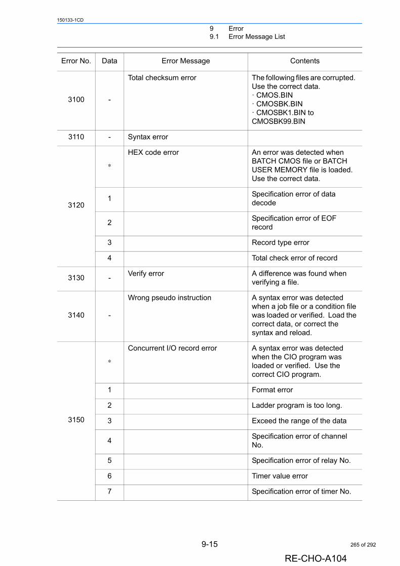
9 Error9.1 Error Message List
150133-1CD
3100 -
Total checksum error The following files are corrupted. Use the correct data. · CMOS.BIN· CMOSBK.BIN· CMOSBK1.BIN to CMOSBK99.BIN
3110 - Syntax error
3120
∗
HEX code error An error was detected when BATCH CMOS file or BATCH USER MEMORY file is loaded. Use the correct data.
1Specification error of data decode
2Specification error of EOF record
3 Record type error
4 Total check error of record
3130 -Verify error A difference was found when
verifying a file.
3140 -
Wrong pseudo instruction A syntax error was detected when a job file or a condition file was loaded or verified. Load the correct data, or correct the syntax and reload.
3150
∗
Concurrent I/O record error A syntax error was detected when the CIO program was loaded or verified. Use the correct CIO program.
1 Format error
2 Ladder program is too long.
3 Exceed the range of the data
4Specification error of channel No.
5 Specification error of relay No.
6 Timer value error
7 Specification error of timer No.
Error No. Data Error Message Contents
9-15
RE-CHO-A104
265 of 292
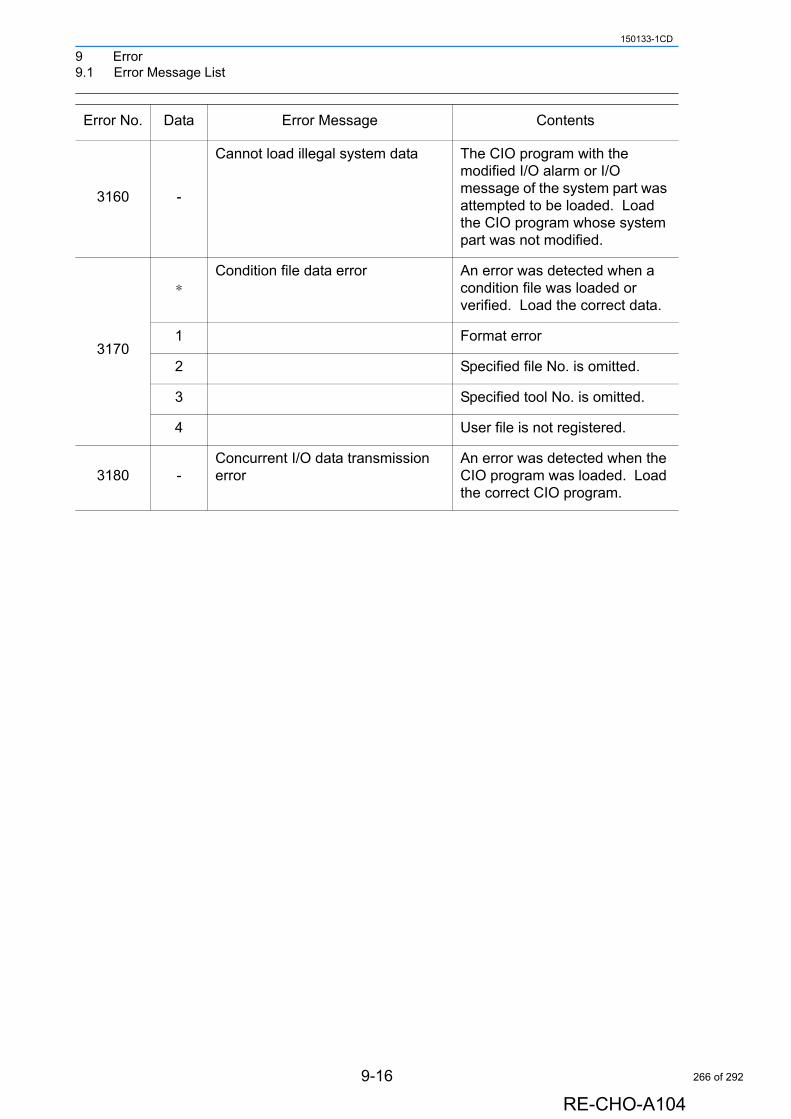
9 Error9.1 Error Message List
150133-1CD
3160 -
Cannot load illegal system data The CIO program with the modified I/O alarm or I/O message of the system part was attempted to be loaded. Load the CIO program whose system part was not modified.
3170
∗Condition file data error An error was detected when a
condition file was loaded or verified. Load the correct data.
1 Format error
2 Specified file No. is omitted.
3 Specified tool No. is omitted.
4 User file is not registered.
3180 -Concurrent I/O data transmission error
An error was detected when the CIO program was loaded. Load the correct CIO program.
Error No. Data Error Message Contents
9-16
RE-CHO-A104
266 of 292
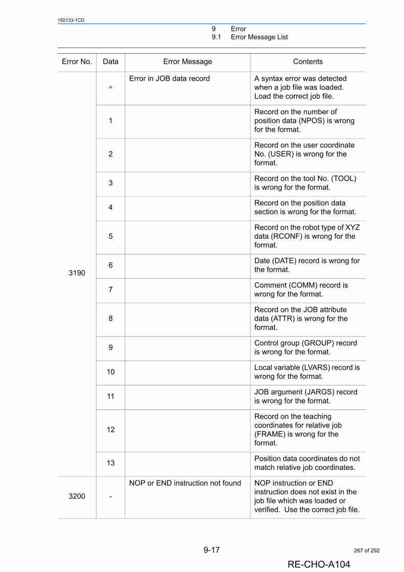
9 Error9.1 Error Message List
150133-1CD
3190
∗Error in JOB data record A syntax error was detected
when a job file was loaded. Load the correct job file.
1Record on the number of position data (NPOS) is wrong for the format.
2Record on the user coordinate No. (USER) is wrong for the format.
3Record on the tool No. (TOOL) is wrong for the format.
4Record on the position data section is wrong for the format.
5Record on the robot type of XYZ data (RCONF) is wrong for the format.
6Date (DATE) record is wrong for the format.
7Comment (COMM) record is wrong for the format.
8Record on the JOB attribute data (ATTR) is wrong for the format.
9Control group (GROUP) record is wrong for the format.
10Local variable (LVARS) record is wrong for the format.
11JOB argument (JARGS) record is wrong for the format.
12
Record on the teaching coordinates for relative job (FRAME) is wrong for the format.
13Position data coordinates do not match relative job coordinates.
3200 -
NOP or END instruction not found NOP instruction or END instruction does not exist in the job file which was loaded or verified. Use the correct job file.
Error No. Data Error Message Contents
9-17
RE-CHO-A104
267 of 292

9 Error9.1 Error Message List
150133-1CD
3210 -Position No. storage area not found Failed to read the position data
when a job file was loaded. Load the correct job file.
Error No. Data Error Message Contents
9-18
RE-CHO-A104
268 of 292

9 Error9.1 Error Message List
150133-1CD
3220
∗ Syntax error in instruction data
2 Interior control error
3 Undefined instruction/tag
4 Instruction/tag shortage
5 Disuse instruction/tag
6 Sub instruction
7 No instruction
8 Invalid instruction
9 Invalid tag
10 Invalid character
11 Undefined intermediate code
12 Intermediate code shortage
13 Syntax stack overflow
14 Syntax stack underflow
15Array type tag uncompleted Tag [ARRAY]
16Element type tag uncompleted Tag [ELEMENT]
17 Macro JOB unregistered
18 Input format error
19 Data size over
20 MIN value over
21 MAX value over
22 Operation expression error
23 Job call argument setting error
24Macro job call argument setting error
25 Position vector setting error
26 System error
27 Soft key designate error
28 Numerical input buffer overflow
Error No. Data Error Message Contents
9-19
RE-CHO-A104
269 of 292
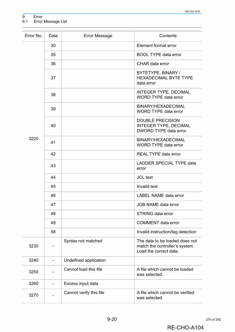
9 Error9.1 Error Message List
150133-1CD
3220
30 Element format error
35 BOOL TYPE data error
36 CHAR data error
37BYTETYPE, BINARY / HEXADECIMAL BYTE TYPE data error
38INTEGER TYPE, DECIMAL WORD TYPE data error
39BINARY/HEXADECIMAL WORD TYPE data error
40DOUBLE PRECISION INTEGER TYPE, DECIMAL DWORD TYPE data error
41BINARY/HEXADECIMAL WORD TYPE data error
42 REAL TYPE data error
43LADDER SPECIAL TYPE data error
44 JCL text
45 Invalid text
46 LABEL NAME data error
47 JOB NAME data error
48 STRING data error
49 COMMENT data error
58 Invalid instruction/tag detection
3230 -Syntax not matched The data to be loaded does not
match the controller’s system. Load the correct data.
3240 - Undefined application
3250 -Cannot load this file A file which cannot be loaded
was selected.
3260 - Excess input data
3270 -Cannot verify this file A file which cannot be verified
was selected.
Error No. Data Error Message Contents
9-20
RE-CHO-A104
270 of 292
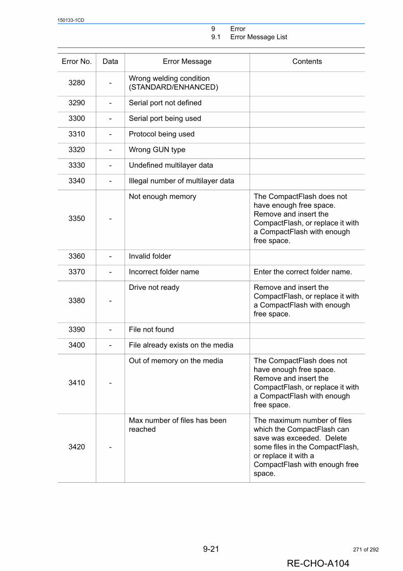
9 Error9.1 Error Message List
150133-1CD
3280 -Wrong welding condition (STANDARD/ENHANCED)
3290 - Serial port not defined
3300 - Serial port being used
3310 - Protocol being used
3320 - Wrong GUN type
3330 - Undefined multilayer data
3340 - Illegal number of multilayer data
3350 -
Not enough memory The CompactFlash does not have enough free space. Remove and insert the CompactFlash, or replace it with a CompactFlash with enough free space.
3360 - Invalid folder
3370 - Incorrect folder name Enter the correct folder name.
3380 -
Drive not ready Remove and insert the CompactFlash, or replace it with a CompactFlash with enough free space.
3390 - File not found
3400 - File already exists on the media
3410 -
Out of memory on the media The CompactFlash does not have enough free space. Remove and insert the CompactFlash, or replace it with a CompactFlash with enough free space.
3420 -
Max number of files has been reached
The maximum number of files which the CompactFlash can save was exceeded. Delete some files in the CompactFlash, or replace it with a CompactFlash with enough free space.
Error No. Data Error Message Contents
9-21
RE-CHO-A104
271 of 292
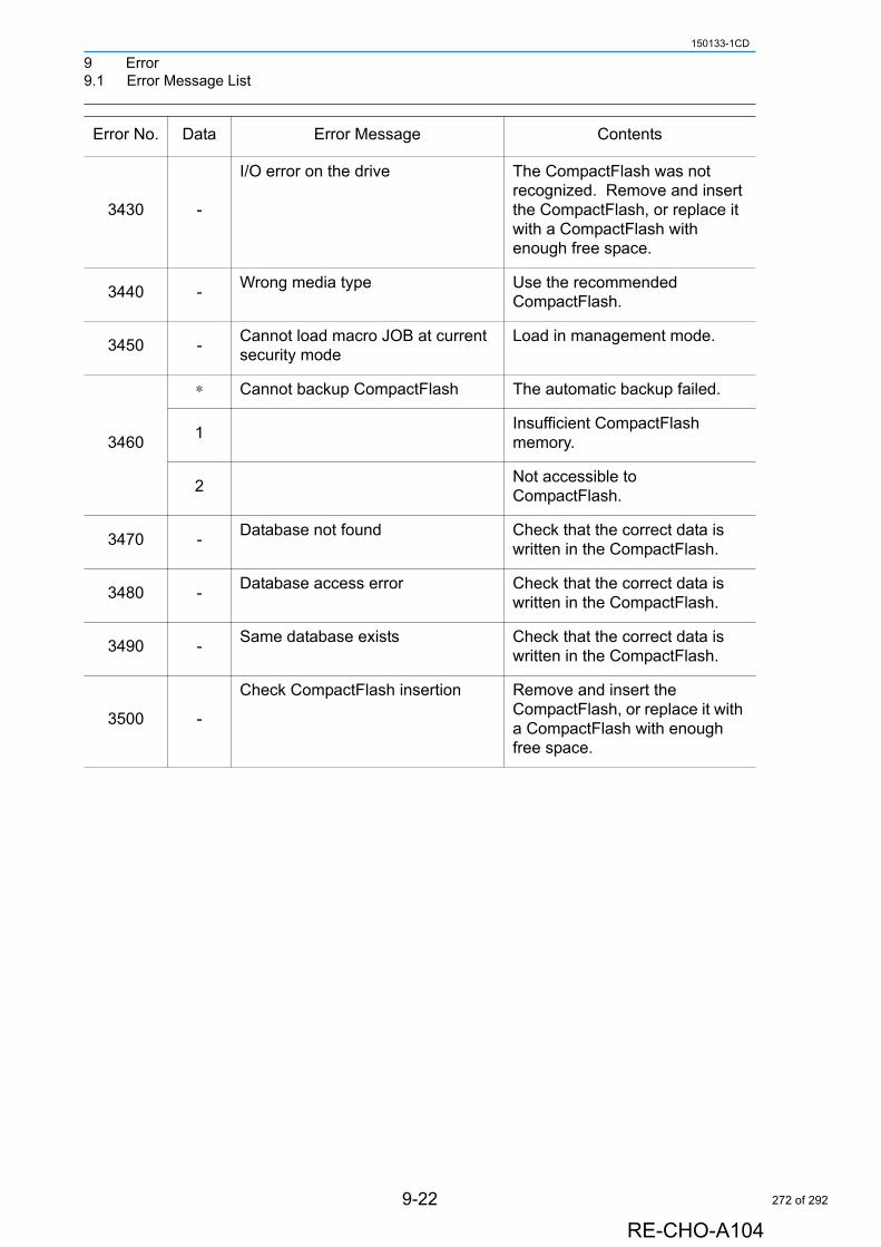
9 Error9.1 Error Message List
150133-1CD
3430 -
I/O error on the drive The CompactFlash was not recognized. Remove and insert the CompactFlash, or replace it with a CompactFlash with enough free space.
3440 -Wrong media type Use the recommended
CompactFlash.
3450 -Cannot load macro JOB at current security mode
Load in management mode.
3460
∗ Cannot backup CompactFlash The automatic backup failed.
1Insufficient CompactFlash memory.
2Not accessible to CompactFlash.
3470 -Database not found Check that the correct data is
written in the CompactFlash.
3480 -Database access error Check that the correct data is
written in the CompactFlash.
3490 -Same database exists Check that the correct data is
written in the CompactFlash.
3500 -
Check CompactFlash insertion Remove and insert the CompactFlash, or replace it with a CompactFlash with enough free space.
Error No. Data Error Message Contents
9-22
RE-CHO-A104
272 of 292

9 Error9.1 Error Message List
150133-1CD
3501
∗ Check CompactFlash insertion The automatic backup failed.
1
The CompactFlash did not have enough free space for automatic backup. Remove and insert the CompactFlash, or replace it with a CompactFlash with enough free space.
2
A CompactFlash access error occurred during automatic backup. Remove and insert the CompactFlash, or replace it with a CompactFlash with enough free space.
3
The automatic backup failed. Remove and insert the CompactFlash, or replace it with a CompactFlash with enough free space.
4
The automatic backup failed. Remove and insert the CompactFlash, or replace it with a CompactFlash with enough free space.
5
The automatic backup failed. Remove and insert the CompactFlash, or replace it with a CompactFlash with enough free space.
6
Failed to delete old automatic backup data. Remove and insert the CompactFlash, or replace it with a CompactFlash with enough free space.
7
Failed to delete old automatic backup data. Remove and insert the CompactFlash, or replace it with a CompactFlash with enough free space.
Error No. Data Error Message Contents
9-23
RE-CHO-A104
273 of 292
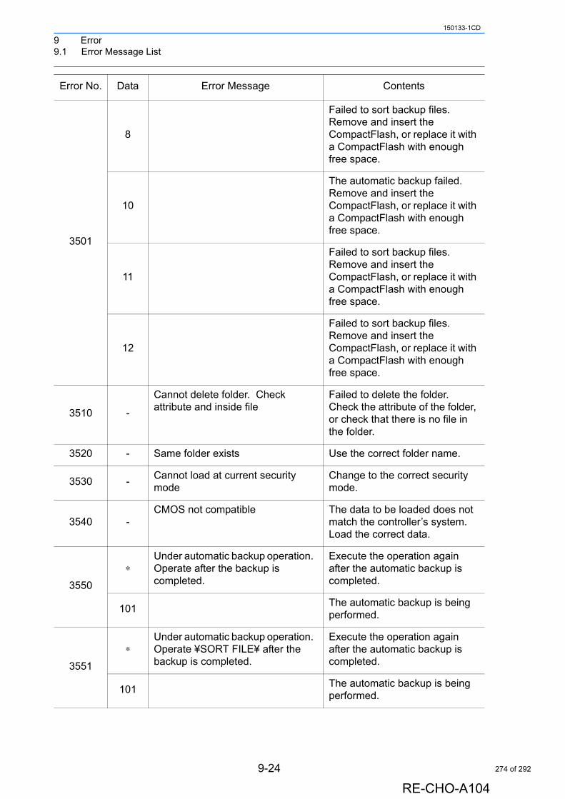
9 Error9.1 Error Message List
150133-1CD
3501
8
Failed to sort backup files. Remove and insert the CompactFlash, or replace it with a CompactFlash with enough free space.
10
The automatic backup failed. Remove and insert the CompactFlash, or replace it with a CompactFlash with enough free space.
11
Failed to sort backup files. Remove and insert the CompactFlash, or replace it with a CompactFlash with enough free space.
12
Failed to sort backup files. Remove and insert the CompactFlash, or replace it with a CompactFlash with enough free space.
3510 -
Cannot delete folder. Check attribute and inside file
Failed to delete the folder. Check the attribute of the folder, or check that there is no file in the folder.
3520 - Same folder exists Use the correct folder name.
3530 -Cannot load at current security mode
Change to the correct security mode.
3540 -CMOS not compatible The data to be loaded does not
match the controller’s system. Load the correct data.
3550
∗Under automatic backup operation. Operate after the backup is completed.
Execute the operation again after the automatic backup is completed.
101The automatic backup is being performed.
3551
∗Under automatic backup operation. Operate ¥SORT FILE¥ after the backup is completed.
Execute the operation again after the automatic backup is completed.
101The automatic backup is being performed.
Error No. Data Error Message Contents
9-24
RE-CHO-A104
274 of 292
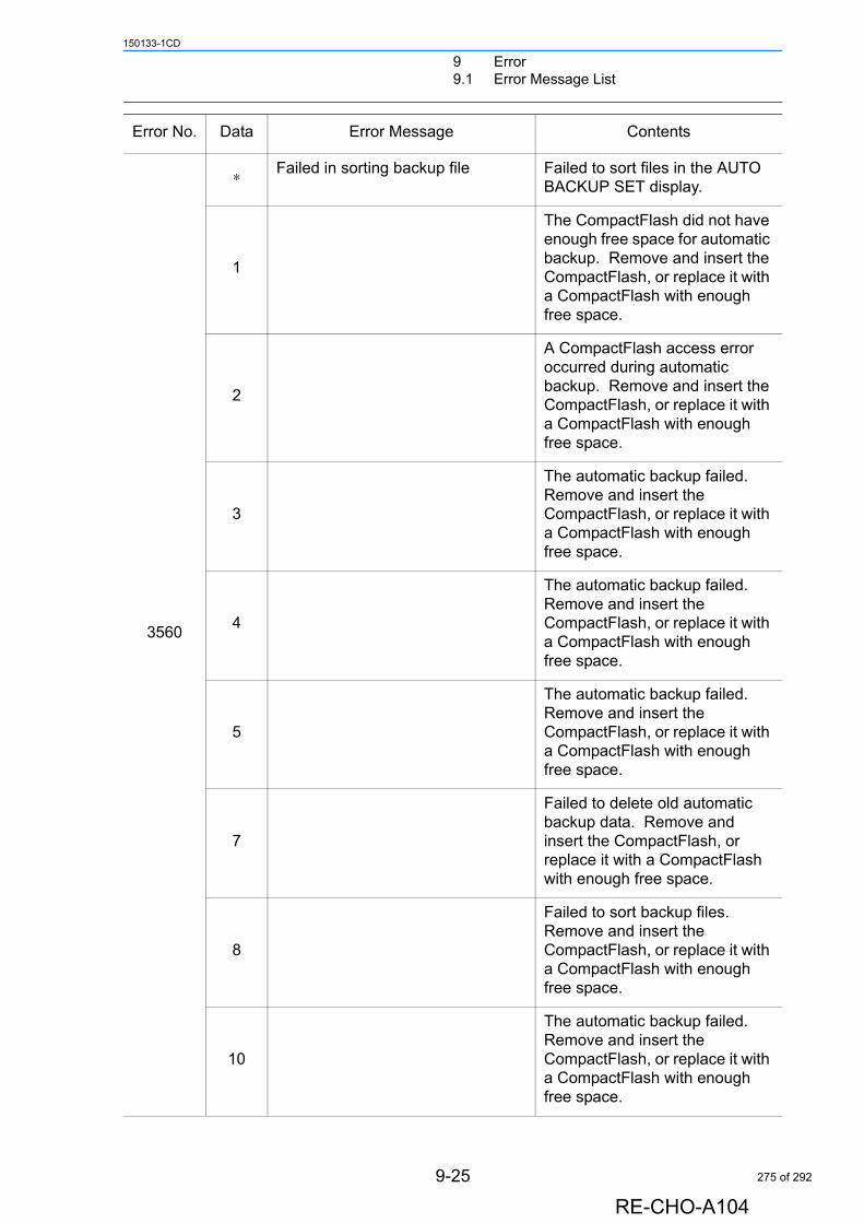
9 Error9.1 Error Message List
150133-1CD
3560
∗ Failed in sorting backup file Failed to sort files in the AUTO BACKUP SET display.
1
The CompactFlash did not have enough free space for automatic backup. Remove and insert the CompactFlash, or replace it with a CompactFlash with enough free space.
2
A CompactFlash access error occurred during automatic backup. Remove and insert the CompactFlash, or replace it with a CompactFlash with enough free space.
3
The automatic backup failed. Remove and insert the CompactFlash, or replace it with a CompactFlash with enough free space.
4
The automatic backup failed. Remove and insert the CompactFlash, or replace it with a CompactFlash with enough free space.
5
The automatic backup failed. Remove and insert the CompactFlash, or replace it with a CompactFlash with enough free space.
7
Failed to delete old automatic backup data. Remove and insert the CompactFlash, or replace it with a CompactFlash with enough free space.
8
Failed to sort backup files. Remove and insert the CompactFlash, or replace it with a CompactFlash with enough free space.
10
The automatic backup failed. Remove and insert the CompactFlash, or replace it with a CompactFlash with enough free space.
Error No. Data Error Message Contents
9-25
RE-CHO-A104
275 of 292
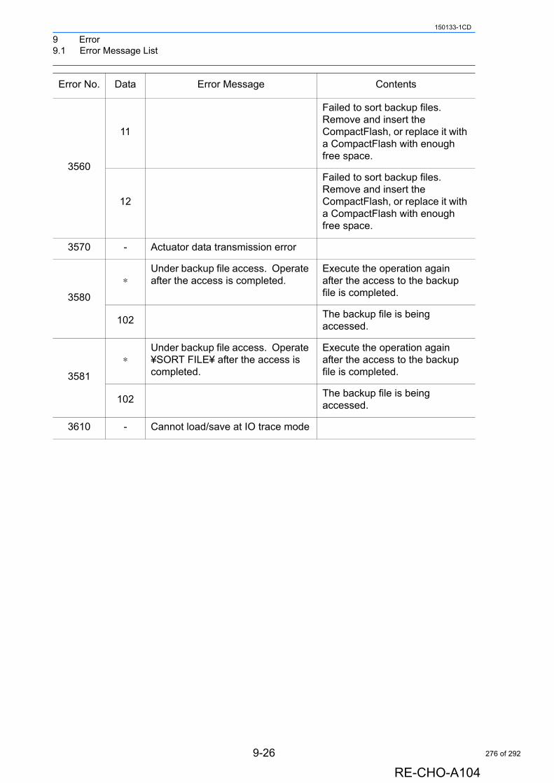
9 Error9.1 Error Message List
150133-1CD
3560
11
Failed to sort backup files. Remove and insert the CompactFlash, or replace it with a CompactFlash with enough free space.
12
Failed to sort backup files. Remove and insert the CompactFlash, or replace it with a CompactFlash with enough free space.
3570 - Actuator data transmission error
3580
∗Under backup file access. Operate after the access is completed.
Execute the operation again after the access to the backup file is completed.
102The backup file is being accessed.
3581
∗Under backup file access. Operate ¥SORT FILE¥ after the access is completed.
Execute the operation again after the access to the backup file is completed.
102The backup file is being accessed.
3610 - Cannot load/save at IO trace mode
Error No. Data Error Message Contents
9-26
RE-CHO-A104
276 of 292
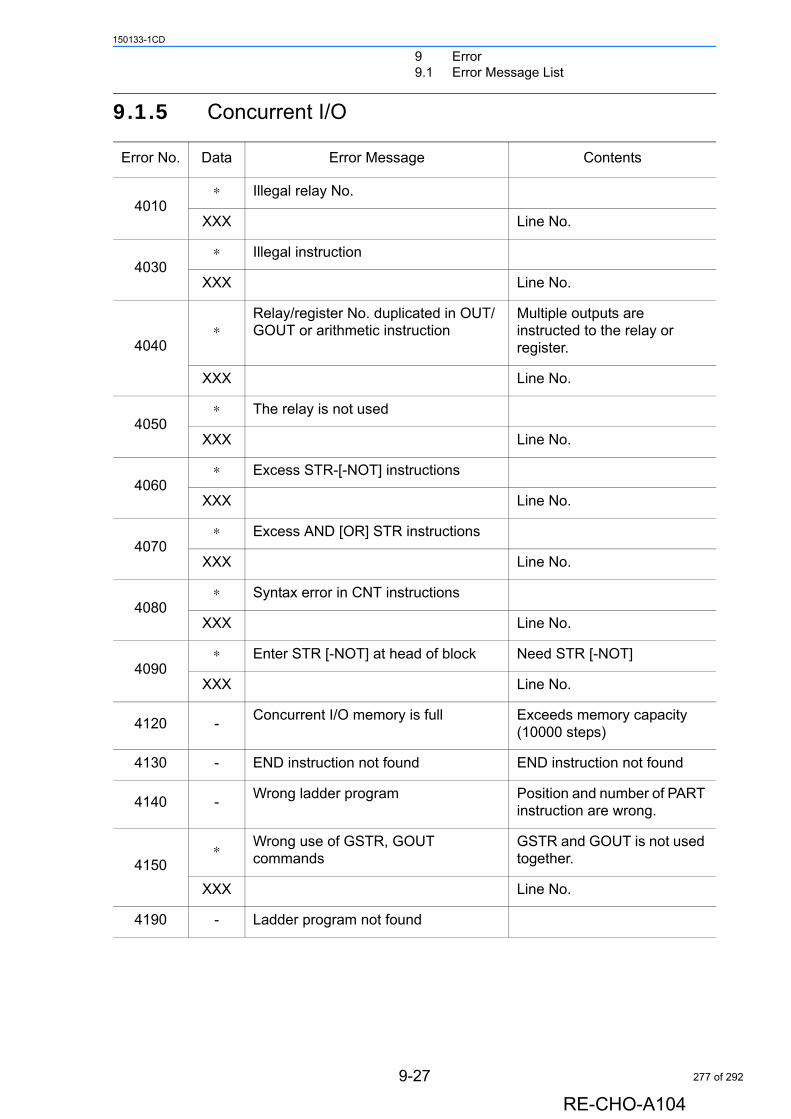
9 Error9.1 Error Message List
150133-1CD
9.1.5 Concurrent I/O
Error No. Data Error Message Contents
4010∗ Illegal relay No.
XXX Line No.
4030∗ Illegal instruction
XXX Line No.
4040∗
Relay/register No. duplicated in OUT/ GOUT or arithmetic instruction
Multiple outputs are instructed to the relay or register.
XXX Line No.
4050∗ The relay is not used
XXX Line No.
4060∗ Excess STR-[-NOT] instructions
XXX Line No.
4070∗ Excess AND [OR] STR instructions
XXX Line No.
4080∗ Syntax error in CNT instructions
XXX Line No.
4090∗ Enter STR [-NOT] at head of block Need STR [-NOT]
XXX Line No.
4120 -Concurrent I/O memory is full Exceeds memory capacity
(10000 steps)
4130 - END instruction not found END instruction not found
4140 -Wrong ladder program Position and number of PART
instruction are wrong.
4150∗ Wrong use of GSTR, GOUT
commandsGSTR and GOUT is not used together.
XXX Line No.
4190 - Ladder program not found
9-27
RE-CHO-A104
277 of 292
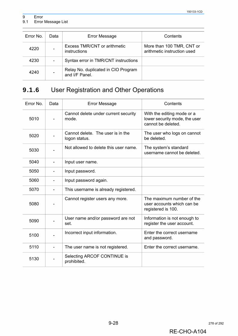
9 Error9.1 Error Message List
150133-1CD
9.1.6 User Registration and Other Operations
4220 -Excess TMR/CNT or arithmetic instructions
More than 100 TMR, CNT or arithmetic instruction used
4230 - Syntax error in TMR/CNT instructions
4240 -Relay No. duplicated in CIO Program and I/F Panel.
Error No. Data Error Message Contents
5010 -Cannot delete under current security mode.
With the editing mode or a lower security mode, the user cannot be deleted.
5020 -Cannot delete. The user is in the logon status.
The user who logs on cannot be deleted.
5030 -Not allowed to delete this user name. The system’s standard
username cannot be deleted.
5040 - Input user name.
5050 - Input password.
5060 - Input password again.
5070 - This username is already registered.
5080 -Cannot register users any more. The maximum number of the
user accounts which can be registered is 100.
5090 -User name and/or password are not set.
Information is not enough to register the user account.
5100 -Incorrect input information. Enter the correct username
and password.
5110 - The user name is not registered. Enter the correct username.
5130 -Selecting ARCOF CONTINUE is prohibited.
Error No. Data Error Message Contents
9-28
RE-CHO-A104
278 of 292
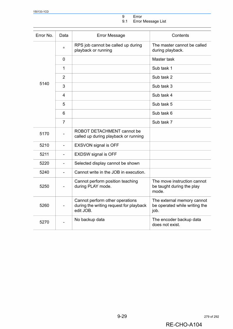
9 Error9.1 Error Message List
150133-1CD
5140
∗ RPS job cannot be called up during playback or running
The master cannot be called during playback.
0 Master task
1 Sub task 1
2 Sub task 2
3 Sub task 3
4 Sub task 4
5 Sub task 5
6 Sub task 6
7 Sub task 7
5170 -ROBOT DETACHMENT cannot be called up during playback or running
5210 - EXSVON signal is OFF
5211 - EXDSW signal is OFF
5220 - Selected display cannot be shown
5240 - Cannot write in the JOB in execution.
5250 -Cannot perform position teaching during PLAY mode.
The move instruction cannot be taught during the play mode.
5260 -Cannot perform other operations during the writing request for playback edit JOB.
The external memory cannot be operated while writing the job.
5270 -No backup data The encoder backup data
does not exist.
Error No. Data Error Message Contents
9-29
RE-CHO-A104
279 of 292
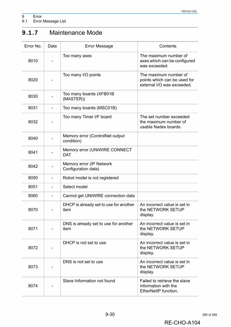
9 Error9.1 Error Message List
150133-1CD
9.1.7 Maintenance Mode
Error No. Data Error Message Contents
8010 -Too many axes The maximum number of
axes which can be configured was exceeded.
8020 -Too many I/O points The maximum number of
points which can be used for external I/O was exceeded.
8030 -Too many boards (XFB01B (MASTER))
8031 - Too many boards (MSC01B)
8032 -Too many Timer I/F board The set number exceeded
the maximum number of usable Nadex boards.
8040 -Memory error (ControlNet output condition)
8041 -Memory error (UNIWIRE CONNECT DAT
8042 -Memory error (IP Network Configuration data)
8050 - Robot model is not registered
8051 - Select model
8060 - Cannot get UNIWIRE connection data
8070 -DHCP is already set to use for another item
An incorrect value is set in the NETWORK SETUP display.
8071 -DNS is already set to use for another item
An incorrect value is set in the NETWORK SETUP display.
8072 -DHCP is not set to use An incorrect value is set in
the NETWORK SETUP display.
8073 -DNS is not set to use An incorrect value is set in
the NETWORK SETUP display.
8074 -Slave Information not found Failed to retrieve the slave
information with the EtherNetIP function.
9-30
RE-CHO-A104
280 of 292
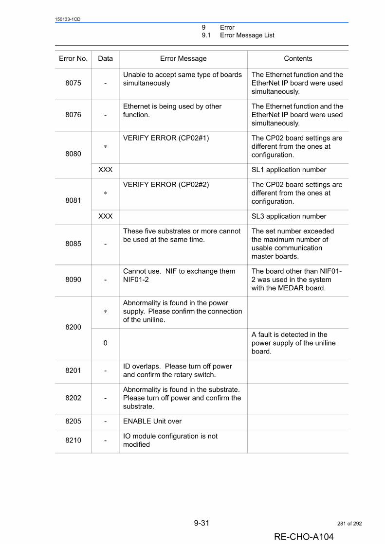
9 Error9.1 Error Message List
150133-1CD
8075 -Unable to accept same type of boards simultaneously
The Ethernet function and the EtherNet IP board were used simultaneously.
8076 -Ethernet is being used by other function.
The Ethernet function and the EtherNet IP board were used simultaneously.
8080∗
VERIFY ERROR (CP02#1) The CP02 board settings are different from the ones at configuration.
XXX SL1 application number
8081∗
VERIFY ERROR (CP02#2) The CP02 board settings are different from the ones at configuration.
XXX SL3 application number
8085 -
These five substrates or more cannot be used at the same time.
The set number exceeded the maximum number of usable communication master boards.
8090 -Cannot use. NIF to exchange them NIF01-2
The board other than NIF01-2 was used in the system with the MEDAR board.
8200
∗Abnormality is found in the power supply. Please confirm the connection of the uniline.
0A fault is detected in the power supply of the uniline board.
8201 -ID overlaps. Please turn off power and confirm the rotary switch.
8202 -Abnormality is found in the substrate. Please turn off power and confirm the substrate.
8205 - ENABLE Unit over
8210 -IO module configuration is not modified
Error No. Data Error Message Contents
9-31
RE-CHO-A104
281 of 292
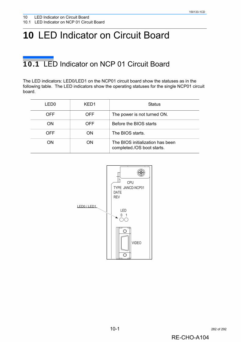
10 LED Indicator on Circuit Board10.1 LED Indicator on NCP 01 Circuit Board
150133-1CD
10 LED Indicator on Circuit Board
10.1 LED Indicator on NCP 01 Circuit Board
The LED indicators: LED0/LED1 on the NCP01 circuit board show the statuses as in the following table. The LED indicators show the operating statuses for the single NCP01 circuit board.
LED0 KED1 Status
OFF OFF The power is not turned ON.
ON OFF Before the BIOS starts
OFF ON The BIOS starts.
ON ON The BIOS initialization has been completed./OS boot starts.
CPU
DATE
0
REV
1
TYPE JANCD-NCP01
LED
VIDEO
LED0 / LED1
10-1
RE-CHO-A104
282 of 292
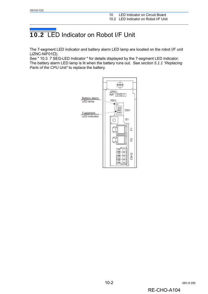
10 LED Indicator on Circuit Board10.2 LED Indicator on Robot I/F Unit
150133-1CD
10.2 LED Indicator on Robot I/F Unit
The 7-segment LED indicator and battery alarm LED lamp are located on the robot I/F unit (JZNC-NIF01). See " 10.3 7 SEG-LED Indicator " for details displayed by the 7-segment LED indicator. The battery alarm LED lamp is lit when the battery runs out. See section 5.1.1 “Replacing Parts of the CPU Unit” to replace the battery.
JZNC-NIF 01-1
PEV.
DS1
S1
F1F2
CN
12
Battery alarmLED lamp
7-segmentLED indicator
10-2
RE-CHO-A104
283 of 292

10 LED Indicator on Circuit Board10.3 7 SEG-LED Indicator
150133-1CD
10.3 7 SEG-LED Indicator
The following tables show the operating statues for JANCD-NIF01/SGDR-AXA01/SGDR-AXA02/JANCD-NCP02. The operating statuses are indicated by 7 SEG-LED.
[Normal Indication]
[Error Indication]
Status
NX100
NIF Circuit Board AXA Circuit BoardNCP02 Circuit
Board
Right after applying the power
All 7-SEG indicators light up.(‘8’, ‘+’, ‘.’ light up.)
During the start-up process
Counts up from ‘O’ toward ‘d’.
After starting up normally
‘d’, ‘+’, ‘.’ blink every one second.
Status
NX100
NIF Circuit Board AXA Circuit BoardNCP02 Circuit
Board
Alarms occurrence in the Main CPU and servo CPU communication system
‘d’, ‘+’, ‘.’ blink every one second.
The error cause is indicated by 7 SEG-LED.(See the indication
spec .)‘d’, ‘+’, ‘.’ blink every
one second.
Normal alarms other than alarms described above
‘d’, ‘+’, ‘.’ blink every one second.
Fatal alarms occurrence
The error cause and the address where the error has occurred are indicated by 7 SEG-LED.
(See the indication spec .)
Indication Spec E.g.) The cycle: [F] [0] [0] [3] [.] is repeated. : Error cause
1
2
SUPPLE-MENT
1
10-3
RE-CHO-A104
284 of 292
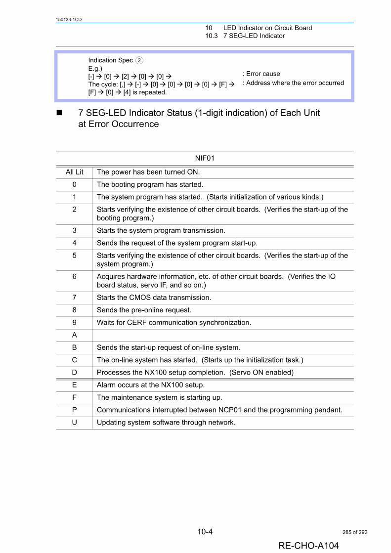
10 LED Indicator on Circuit Board10.3 7 SEG-LED Indicator
150133-1CD
7 SEG-LED Indicator Status (1-digit indication) of Each Unit at Error Occurrence
Indication Spec E.g.)[-] [0] [2] [0] [0] The cycle: [,] [-] [0] [0] [0] [0] [F] [F] [0] [4] is repeated.
: Error cause
: Address where the error occurred
NIF01
All Lit The power has been turned ON.
0 The booting program has started.
1 The system program has started. (Starts initialization of various kinds.)
2 Starts verifying the existence of other circuit boards. (Verifies the start-up of the booting program.)
3 Starts the system program transmission.
4 Sends the request of the system program start-up.
5 Starts verifying the existence of other circuit boards. (Verifies the start-up of the system program.)
6 Acquires hardware information, etc. of other circuit boards. (Verifies the IO board status, servo IF, and so on.)
7 Starts the CMOS data transmission.
8 Sends the pre-online request.
9 Waits for CERF communication synchronization.
A
B Sends the start-up request of on-line system.
C The on-line system has started. (Starts up the initialization task.)
D Processes the NX100 setup completion. (Servo ON enabled)
E Alarm occurs at the NX100 setup.
F The maintenance system is starting up.
P Communications interrupted between NCP01 and the programming pendant.
U Updating system software through network.
2
10-4
RE-CHO-A104
285 of 292
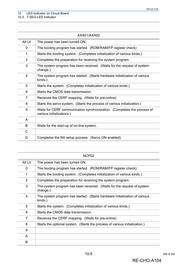
10 LED Indicator on Circuit Board10.3 7 SEG-LED Indicator
150133-1CD
AXA01/AXA02
All Lit The power has been turned ON.
0 The booting program has started. (ROM/RAM/FP register check)
1 Starts the booting system. (Completes initialization of various kinds.)
2 Completes the preparation for receiving the system program.
3 The system program has been received. (Waits for the request of system change.)
4 The system program has started. (Starts hardware initialization of various kinds.)
5 Starts the system. (Completes initialization of various kinds.)
6 Starts the CMOS data transmission.
7 Receives the CERF mapping. (Waits for pre-online)
8 Starts the servo system. (Starts the process of various initialization.)
9 Waits for CERF communication synchronization. (Completes the process of various initializations.)
A
B Waits for the start-up of on-line system.
C
D Completes the NX setup process. (Servo ON enabled)
NCP02
All Lit The power has been turned ON.
0 The booting program has started. (ROM/RAM/FP register check)
1 Starts the booting system. (Completes initialization of various kinds.)
2 Completes the preparation for receiving the system program.
3 The system program has been received. (Waits for the request of system change.)
4 The system program has started. (Starts hardware initialization of various kinds.)
5 Starts the system. (Completes initialization of various kinds.)
6 Starts the CMOS data transmission.
7 Receives the CERF mapping. (Waits for pre-online)
8 Starts the optional system. (Starts the process of various initialization.)
9
A
B
10-5
RE-CHO-A104
286 of 292
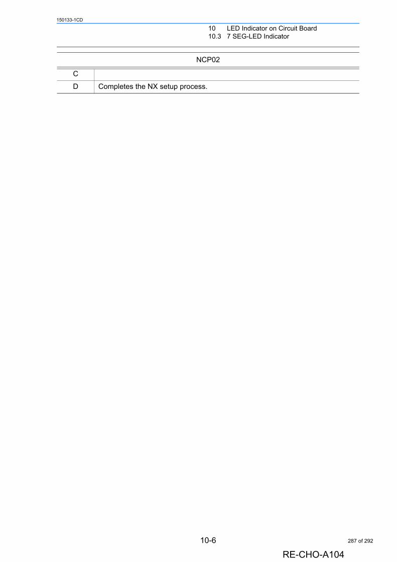
10 LED Indicator on Circuit Board10.3 7 SEG-LED Indicator
150133-1CD
C
D Completes the NX setup process.
NCP02
10-6
RE-CHO-A104
287 of 292
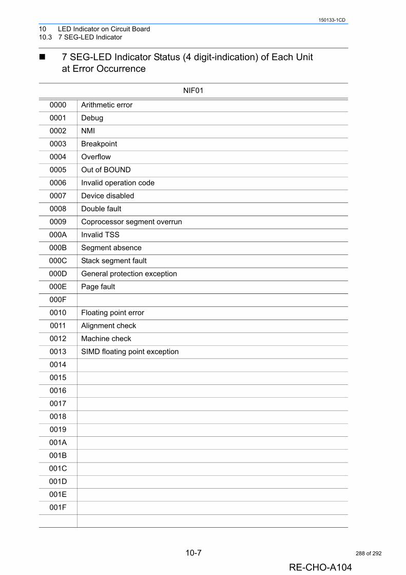
10 LED Indicator on Circuit Board10.3 7 SEG-LED Indicator
150133-1CD
7 SEG-LED Indicator Status (4 digit-indication) of Each Unit at Error Occurrence
NIF01
0000 Arithmetic error
0001 Debug
0002 NMI
0003 Breakpoint
0004 Overflow
0005 Out of BOUND
0006 Invalid operation code
0007 Device disabled
0008 Double fault
0009 Coprocessor segment overrun
000A Invalid TSS
000B Segment absence
000C Stack segment fault
000D General protection exception
000E Page fault
000F
0010 Floating point error
0011 Alignment check
0012 Machine check
0013 SIMD floating point exception
0014
0015
0016
0017
0018
0019
001A
001B
001C
001D
001E
001F
10-7
RE-CHO-A104
288 of 292
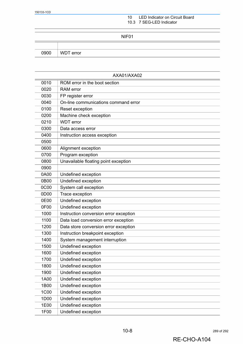
10 LED Indicator on Circuit Board10.3 7 SEG-LED Indicator
150133-1CD
0900 WDT error
AXA01/AXA02
0010 ROM error in the boot section
0020 RAM error
0030 FP register error
0040 On-line communications command error
0100 Reset exception
0200 Machine check exception
0210 WDT error
0300 Data access error
0400 Instruction access exception
0500
0600 Alignment exception
0700 Program exception
0800 Unavailable floating point exception
0900
0A00 Undefined exception
0B00 Undefined exception
0C00 System call exception
0D00 Trace exception
0E00 Undefined exception
0F00 Undefined exception
1000 Instruction conversion error exception
1100 Data load conversion error exception
1200 Data store conversion error exception
1300 Instruction breakpoint exception
1400 System management interruption
1500 Undefined exception
1600 Undefined exception
1700 Undefined exception
1800 Undefined exception
1900 Undefined exception
1A00 Undefined exception
1B00 Undefined exception
1C00 Undefined exception
1D00 Undefined exception
1E00 Undefined exception
1F00 Undefined exception
NIF01
10-8
RE-CHO-A104
289 of 292
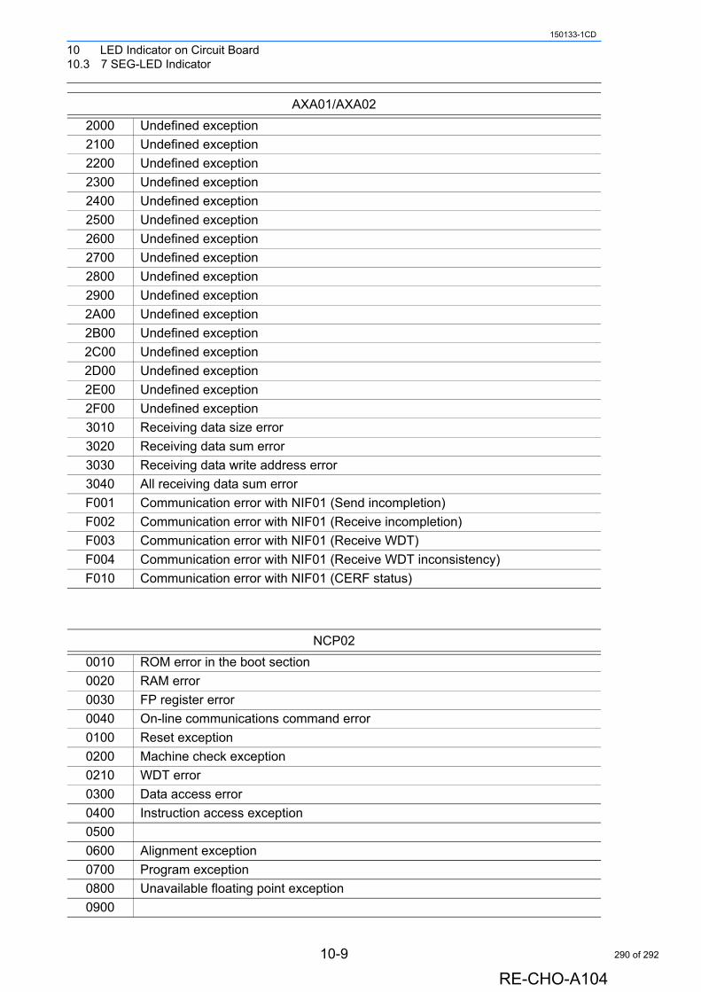
10 LED Indicator on Circuit Board10.3 7 SEG-LED Indicator
150133-1CD
2000 Undefined exception
2100 Undefined exception
2200 Undefined exception
2300 Undefined exception
2400 Undefined exception
2500 Undefined exception
2600 Undefined exception
2700 Undefined exception
2800 Undefined exception
2900 Undefined exception
2A00 Undefined exception
2B00 Undefined exception
2C00 Undefined exception
2D00 Undefined exception
2E00 Undefined exception
2F00 Undefined exception
3010 Receiving data size error
3020 Receiving data sum error
3030 Receiving data write address error
3040 All receiving data sum error
F001 Communication error with NIF01 (Send incompletion)
F002 Communication error with NIF01 (Receive incompletion)
F003 Communication error with NIF01 (Receive WDT)
F004 Communication error with NIF01 (Receive WDT inconsistency)
F010 Communication error with NIF01 (CERF status)
NCP02
0010 ROM error in the boot section
0020 RAM error
0030 FP register error
0040 On-line communications command error
0100 Reset exception
0200 Machine check exception
0210 WDT error
0300 Data access error
0400 Instruction access exception
0500
0600 Alignment exception
0700 Program exception
0800 Unavailable floating point exception
0900
AXA01/AXA02
10-9
RE-CHO-A104
290 of 292
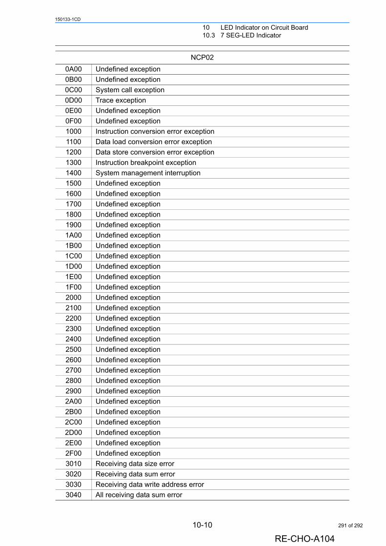
10 LED Indicator on Circuit Board10.3 7 SEG-LED Indicator
150133-1CD
0A00 Undefined exception
0B00 Undefined exception
0C00 System call exception
0D00 Trace exception
0E00 Undefined exception
0F00 Undefined exception
1000 Instruction conversion error exception
1100 Data load conversion error exception
1200 Data store conversion error exception
1300 Instruction breakpoint exception
1400 System management interruption
1500 Undefined exception
1600 Undefined exception
1700 Undefined exception
1800 Undefined exception
1900 Undefined exception
1A00 Undefined exception
1B00 Undefined exception
1C00 Undefined exception
1D00 Undefined exception
1E00 Undefined exception
1F00 Undefined exception
2000 Undefined exception
2100 Undefined exception
2200 Undefined exception
2300 Undefined exception
2400 Undefined exception
2500 Undefined exception
2600 Undefined exception
2700 Undefined exception
2800 Undefined exception
2900 Undefined exception
2A00 Undefined exception
2B00 Undefined exception
2C00 Undefined exception
2D00 Undefined exception
2E00 Undefined exception
2F00 Undefined exception
3010 Receiving data size error
3020 Receiving data sum error
3030 Receiving data write address error
3040 All receiving data sum error
NCP02
10-10
RE-CHO-A104
291 of 292

HEAD OFFICE2-1 Kurosakishiroishi, Yahatanishi-ku, Kitakyushu 806-0004, JapanPhone +81-93-645-7703 Fax +81-93-645-7802
100 Automation Way, Miamisburg, OH 45342, U.S.A. Phone +1-937-847-6200 Fax +1-937-847-6277
YASKAWA America Inc. (Motoman Robotics Division)
Bredbandet 1 vån. 3 varvsholmen 392 30 Kalmar, SwedenPhone +46-480-417-800 Fax +46-480-417-999
YASKAWA Nordic AB
Yaskawastrasse 1, 85391 Allershausen, GermanyPhone +49-8166-90-100 Fax +49-8166-90-103
YASKAWA Europe GmbH Robotics Divsion )
9F, Kyobo Securities Bldg., 26-4, Yeouido-dong, Yeongdeungpo-gu, Seoul 150-737, KoreaPhone +82-2-784-7844 Fax +82-2-784-8495
YASKAWA Electric Korea Co., Ltd
151 Lorong Chuan, #04-02A, New Tech Park, Singapore 556741Phone +65-6282-3003 Fax +65-6289-3003
YASKAWA Electric (Singapore) PTE Ltd.
No7 Yongchang North Road, Beijing E&T Development Area China 100176Phone +86-10-6788-2858 Fax +86-10-6788-2878
YASKAWA SHOUGANG ROBOT Co. Ltd.
#426, Udyog Vihar, Phase- IV, Gurgaon, Haryana, IndiaFax +91-124-475-8542Phone +91-124-475-8500
YASKAWA India Private Ltd. (Robotics Division)
YASKAWA Electric (China) Co., Ltd.22/F One Corporate Avenue No.222, Hubin Road, Huangpu District, Shanghai 200021, ChinaPhone +86-21-5385-2200 Fax 86-21-5385-3299
YASKAWA Electric (Thailand) Co., Ltd.252/125-126 27th Floor, Tower B Muang Thai-Phatra Complex Building,Rachadaphisek Road Huaykwang, Bangkok 10320, ThailandPhone +66-2693-2200 Fax +66-2693-4200
12F, No.207, Sec. 3, Beishin Rd., Shindian District, New Taipei City 23143, TaiwanFax +886-2-8913-1513Phone +886-2-8913-1333
YASKAWA Electric Taiwan Corporation
Secure Building-Gedung B Lantai Dasar & Lantai 1 JI. Raya Protokol Halim Perdanakusuma, Jakarta 13610, Indonesia
Fax +62-21-2982-6741Phone +62-21-2982-6470
PT. YASKAWA Electric Indonesia
Specifications are subject to change without noticefor ongoing product modifications and improvements.
MANUAL NO. 17RE-CHO-A104
NX100MAINTENANCE MANUAL
292 of 292


![[Review of NX100 + 20-50mm lens] Performance of the NX100](https://img.pdfslide.net/doc/110x75/568bef531a28ab89338bc1ae/review-of-nx100-20-50mm-lens-performance-of-the-nx100-56e22b1aa4607.jpg)

